CN1008504B - Method for detecting and correcting failure in mounting of electronic parts on substrate and apparatus therefor - Google Patents
Method for detecting and correcting failure in mounting of electronic parts on substrate and apparatus thereforInfo
- Publication number
- CN1008504B CN1008504B CN86104342A CN86104342A CN1008504B CN 1008504 B CN1008504 B CN 1008504B CN 86104342 A CN86104342 A CN 86104342A CN 86104342 A CN86104342 A CN 86104342A CN 1008504 B CN1008504 B CN 1008504B
- Authority
- CN
- China
- Prior art keywords
- substrate
- mentioned
- electronic unit
- fault
- data
- Prior art date
- Legal status (The legal status is an assumption and is not a legal conclusion. Google has not performed a legal analysis and makes no representation as to the accuracy of the status listed.)
- Expired
Links
Images

Classifications
-
- H—ELECTRICITY
- H05—ELECTRIC TECHNIQUES NOT OTHERWISE PROVIDED FOR
- H05K—PRINTED CIRCUITS; CASINGS OR CONSTRUCTIONAL DETAILS OF ELECTRIC APPARATUS; MANUFACTURE OF ASSEMBLAGES OF ELECTRICAL COMPONENTS
- H05K13/00—Apparatus or processes specially adapted for manufacturing or adjusting assemblages of electric components
- H05K13/08—Monitoring manufacture of assemblages
-
- H—ELECTRICITY
- H01—ELECTRIC ELEMENTS
- H01L—SEMICONDUCTOR DEVICES NOT COVERED BY CLASS H10
- H01L21/00—Processes or apparatus adapted for the manufacture or treatment of semiconductor or solid state devices or of parts thereof
- H01L21/67—Apparatus specially adapted for handling semiconductor or electric solid state devices during manufacture or treatment thereof; Apparatus specially adapted for handling wafers during manufacture or treatment of semiconductor or electric solid state devices or components ; Apparatus not specifically provided for elsewhere
- H01L21/67005—Apparatus not specifically provided for elsewhere
- H01L21/67242—Apparatus for monitoring, sorting or marking
- H01L21/67294—Apparatus for monitoring, sorting or marking using identification means, e.g. labels on substrates or labels on containers
-
- G—PHYSICS
- G01—MEASURING; TESTING
- G01R—MEASURING ELECTRIC VARIABLES; MEASURING MAGNETIC VARIABLES
- G01R31/00—Arrangements for testing electric properties; Arrangements for locating electric faults; Arrangements for electrical testing characterised by what is being tested not provided for elsewhere
- G01R31/26—Testing of individual semiconductor devices
- G01R31/265—Contactless testing
- G01R31/2656—Contactless testing using non-ionising electromagnetic radiation, e.g. optical radiation
-
- H—ELECTRICITY
- H05—ELECTRIC TECHNIQUES NOT OTHERWISE PROVIDED FOR
- H05K—PRINTED CIRCUITS; CASINGS OR CONSTRUCTIONAL DETAILS OF ELECTRIC APPARATUS; MANUFACTURE OF ASSEMBLAGES OF ELECTRICAL COMPONENTS
- H05K13/00—Apparatus or processes specially adapted for manufacturing or adjusting assemblages of electric components
- H05K13/08—Monitoring manufacture of assemblages
- H05K13/081—Integration of optical monitoring devices in assembly lines; Processes using optical monitoring devices specially adapted for controlling devices or machines in assembly lines
- H05K13/0815—Controlling of component placement on the substrate during or after manufacturing
-
- Y—GENERAL TAGGING OF NEW TECHNOLOGICAL DEVELOPMENTS; GENERAL TAGGING OF CROSS-SECTIONAL TECHNOLOGIES SPANNING OVER SEVERAL SECTIONS OF THE IPC; TECHNICAL SUBJECTS COVERED BY FORMER USPC CROSS-REFERENCE ART COLLECTIONS [XRACs] AND DIGESTS
- Y10—TECHNICAL SUBJECTS COVERED BY FORMER USPC
- Y10T—TECHNICAL SUBJECTS COVERED BY FORMER US CLASSIFICATION
- Y10T29/00—Metal working
- Y10T29/49—Method of mechanical manufacture
- Y10T29/49002—Electrical device making
- Y10T29/49117—Conductor or circuit manufacturing
- Y10T29/49124—On flat or curved insulated base, e.g., printed circuit, etc.
- Y10T29/4913—Assembling to base an electrical component, e.g., capacitor, etc.
- Y10T29/49131—Assembling to base an electrical component, e.g., capacitor, etc. by utilizing optical sighting device
-
- Y—GENERAL TAGGING OF NEW TECHNOLOGICAL DEVELOPMENTS; GENERAL TAGGING OF CROSS-SECTIONAL TECHNOLOGIES SPANNING OVER SEVERAL SECTIONS OF THE IPC; TECHNICAL SUBJECTS COVERED BY FORMER USPC CROSS-REFERENCE ART COLLECTIONS [XRACs] AND DIGESTS
- Y10—TECHNICAL SUBJECTS COVERED BY FORMER USPC
- Y10T—TECHNICAL SUBJECTS COVERED BY FORMER US CLASSIFICATION
- Y10T29/00—Metal working
- Y10T29/49—Method of mechanical manufacture
- Y10T29/49002—Electrical device making
- Y10T29/49117—Conductor or circuit manufacturing
- Y10T29/49124—On flat or curved insulated base, e.g., printed circuit, etc.
- Y10T29/4913—Assembling to base an electrical component, e.g., capacitor, etc.
- Y10T29/49133—Assembling to base an electrical component, e.g., capacitor, etc. with component orienting
-
- Y—GENERAL TAGGING OF NEW TECHNOLOGICAL DEVELOPMENTS; GENERAL TAGGING OF CROSS-SECTIONAL TECHNOLOGIES SPANNING OVER SEVERAL SECTIONS OF THE IPC; TECHNICAL SUBJECTS COVERED BY FORMER USPC CROSS-REFERENCE ART COLLECTIONS [XRACs] AND DIGESTS
- Y10—TECHNICAL SUBJECTS COVERED BY FORMER USPC
- Y10T—TECHNICAL SUBJECTS COVERED BY FORMER US CLASSIFICATION
- Y10T29/00—Metal working
- Y10T29/53—Means to assemble or disassemble
- Y10T29/53022—Means to assemble or disassemble with means to test work or product
-
- Y—GENERAL TAGGING OF NEW TECHNOLOGICAL DEVELOPMENTS; GENERAL TAGGING OF CROSS-SECTIONAL TECHNOLOGIES SPANNING OVER SEVERAL SECTIONS OF THE IPC; TECHNICAL SUBJECTS COVERED BY FORMER USPC CROSS-REFERENCE ART COLLECTIONS [XRACs] AND DIGESTS
- Y10—TECHNICAL SUBJECTS COVERED BY FORMER USPC
- Y10T—TECHNICAL SUBJECTS COVERED BY FORMER US CLASSIFICATION
- Y10T29/00—Metal working
- Y10T29/53—Means to assemble or disassemble
- Y10T29/53039—Means to assemble or disassemble with control means energized in response to activator stimulated by condition sensor
- Y10T29/53043—Means to assemble or disassemble with control means energized in response to activator stimulated by condition sensor including means to divert defective work part
-
- Y—GENERAL TAGGING OF NEW TECHNOLOGICAL DEVELOPMENTS; GENERAL TAGGING OF CROSS-SECTIONAL TECHNOLOGIES SPANNING OVER SEVERAL SECTIONS OF THE IPC; TECHNICAL SUBJECTS COVERED BY FORMER USPC CROSS-REFERENCE ART COLLECTIONS [XRACs] AND DIGESTS
- Y10—TECHNICAL SUBJECTS COVERED BY FORMER USPC
- Y10T—TECHNICAL SUBJECTS COVERED BY FORMER US CLASSIFICATION
- Y10T29/00—Metal working
- Y10T29/53—Means to assemble or disassemble
- Y10T29/53039—Means to assemble or disassemble with control means energized in response to activator stimulated by condition sensor
- Y10T29/53048—Multiple station assembly or disassembly apparatus
- Y10T29/53052—Multiple station assembly or disassembly apparatus including position sensor
-
- Y—GENERAL TAGGING OF NEW TECHNOLOGICAL DEVELOPMENTS; GENERAL TAGGING OF CROSS-SECTIONAL TECHNOLOGIES SPANNING OVER SEVERAL SECTIONS OF THE IPC; TECHNICAL SUBJECTS COVERED BY FORMER USPC CROSS-REFERENCE ART COLLECTIONS [XRACs] AND DIGESTS
- Y10—TECHNICAL SUBJECTS COVERED BY FORMER USPC
- Y10T—TECHNICAL SUBJECTS COVERED BY FORMER US CLASSIFICATION
- Y10T29/00—Metal working
- Y10T29/53—Means to assemble or disassemble
- Y10T29/5313—Means to assemble electrical device
- Y10T29/53174—Means to fasten electrical component to wiring board, base, or substrate
- Y10T29/53178—Chip component
Abstract
The present invention relates to a method for detecting and enabling correction of a failure in the mounting of electronic parts on substrates, capable of automatically and efficiently accomplishing the detection of a failure in the mounting of electronic parts on substrates, and classification between failed substrates and acceptable substrates to improve the overall operation efficiency of an electronic parts mounting line. The method is adapted to apply a code mark to each substrate on which electronic parts are to be mounted, detect a failure the mounting after, store the code marks and failure data of failed substrates, and classify the failed substrates from acceptable substrates and transfer the failed substrates on the basis of the failure data stored. In addition, an apparatus used for detecting and enabling correction of a failure in the mounting is disclosed.
Description
The present invention relates to be used for the method and the device thereof of the assembly failure of detected electrons circuit element on substrate, particularly be applicable to any installation fault or a kind of method and apparatus of detecting of defective of electronic circuit component on substrate.As the fault of the electronic unit of part assembling set deviation with respect to substrate, the mistake of installation direction, after this out of order substrate of such installation is called out of order with qualified substrate separates,, these out of order board transport are stood to revise to revising for revising out of order substrate.
Go up in the assembling electronic circuit component conventional production line of (claiming " electronic unit " or " chip " later on) at substrate (claiming " substrate " later on), electronic unit is carried out on each substrate in the inspection of assembly failure on the substrate and defective, when detecting arbitrary installation fault or defective, defective substrate is just removed from production line, and operation is collected in the chip receiver by hand.The defective substrate that will be collected into is so then delivered to the operation of making amendment of independent modification station.
See from above-mentioned, install in the detection and update the system of fault in routine, the inspection of fault or defective is installed to be carried out on each substrate, be that the installation of convenient electronic unit on substrate is effectively and is to carry out in chip installation station continuously that this can not improve operating efficiency total on the production line.Also have, the fault in installation comprises loading error, and electronic unit is with respect to the misregistration of substrate, and the mistake of installation direction has been installed incorrect electronic unit and analogue on substrate.Unfortunately, the defective mounting of changeful form like this is difficult to accurately and effectively check.Moreover, for at the defective substrate of an independent overhaul stand correction, remove defective substrate from production line, must be used for manual carrying out, and require the operator that each defective substrate is done mark at the position of each fault, so retouching operation is quite to bother and poor efficiency.
The above-mentioned shortcoming that The present invention be directed to prior art generates.
Therefore, an object of the present invention is to provide a kind of method, in order to the installation situation of detection electronics on substrate, and can check a plurality of chips that are assemblied on the substrate simultaneously, between defective substrate and flawless substrate, automatically and effectively classify, can revise defective substrate with the concentrated area effectively.
Another object of the present invention provides a device, be used for detection electronics at the assembly failure on the substrate and can check a plurality of chips that are assemblied on the substrate simultaneously, between defectiveness and zero defect substrate, automatically and effectively classify, revise defective substrate with the concentrated area effectively.
Another object of the present invention provides a method, the installation situation of detection electronics on substrate, and can be accurately and easily check the installation situation of circuit block on each substrate according to the structure of circuit block.
According to the present invention, be provided for the method for the installation fault of detection electronics on substrate, this method comprises more following steps: apply a code signing on each surface that the substrate of electronic unit will be installed, many substrates are arranged in rows; Observation is installed in the electronic unit image on the substrate; The image of check circuit parts one by one, and produce the detection data that electronic unit installation situation on the substrate is shown; Read on the substrate code signing with the code signing data handling and expression is read with the power on detection storage of subassembly installation situation of corresponding substrate be shown be in the same place, and with board transport to the station of fault substrate from the classification of qualified substrate, according to the storage the detection data and code signing data identification fault substrate so that itself and qualified substrate are separated, and with these fault board transport to the station that is used to revise fault, inspection data and code signing data according to storage are revised the fault substrate, and code signing can be formed by bar code.
According to optimum implementation of the present invention, the step of the image of electronic unit is installed in observation on substrate, the image step of continuous review electronic unit comprises, carry out rayed downwards on substrate, to form the shadow region of a relevant electronic unit to having the substrate that electronic unit is installed, along on a plurality of points in edge of image of component that have shade hypographous electronic unit partly being demarcated, to the contrast of examining local description image and shade and shade fault with electronic unit installation situation on the detection substrate.
According to a further aspect in the invention, a kind ofly be used to check that electronic unit installs the device of failure condition on substrate, it comprises that the dress that the surface with each substrate that electronic unit is installed is applied the different code mark adorns an x-y platform and be used for a plurality of substrates are aligned thereon, a plurality of detection cameras place on the x-y platform, place corresponding position with the substrate of aligning, subjectoscope is electrically connected with the camera of inspection, be used for continuous review illustrates the substrate element installation situation with generation from the image of described inspection camera supply inspection data, sorting mechanism is used to carry out the classification of fault substrate and qualified substrate, be used to illustrate the device of each details on faults that the fault substrate is arranged so that carry out the correction of each fault substrate, be combined in the x-y platform respectively and the first and second code signing readers in the device be shown and device is shown and read, append to the code signing on each substrate, and data edition controller, it is to be electrically connected with image detector and sorting mechanism, the data edition controller comprises the device that is used to handle with the inspection data of memory substrate, these data are to provide with the code signing data of being read corresponding substrate by the first code mark reader from the figure detector that boils, the data edition controller be also included within the code signing data that are stored in wherein and the code signing read by the first code mark reader between compare device with identification fault substrate, sorting mechanism can carry out its classification like this, and fault illustrates device and calls out and cry code signing that the inspection data that are stored in fault substrate in the data edition controller depend on each fault substrate of being read by the second code mark reader to illustrate by the details of call data.
By following detailed and simultaneously with reference to the description of the drawings, being easy to has further understanding to other purpose of the present invention and many bonus thereof, identical reference number in the accompanying drawing is represented identical or corresponding parts, and wherein: Fig. 1 is the goods batch figure that shows first embodiment of the system of the assembly failure of detection electronics on substrate according to the present invention.
Fig. 2 shows the plane graph that is applicable to substrate example of the present invention.
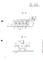
Fig. 3 is one and has shown the test section that is incorporated into embodiment shown in Figure 1, is used for the stereogram of the installation failure condition of detection electronics on substrate.
Fig. 4 is a schematic diagram that shows the example of the detection camera that is applicable to that test section shown in Figure 3 is used.
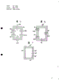
Fig. 5 to Fig. 7 is for explaining the auxiliary schematic diagram according to second embodiment of the invention.
To Fig. 3, the method and apparatus that is used to detect the installation failure condition on substrate is described according to first embodiment of the present invention referring now to Fig. 1.Reference digital 10 is the devices that are used for installing electronic unit on substrate in Fig. 1.After fault had been carried out the fitting operation of electronic unit by erecting device 10, substrate was transferred to x-y platform 54 by load device 56, and code signing device 58 is applied to different code signings on the surface of each substrate during this period.
As shown in Figure 3, x-y workbench 54 is suitable for that a plurality of substrates 14 are arranged in rows in the above or is arranged side by side to give fixed interval, the suitable camera of quantity and substrate 14 60 is stable to be installed in the top position that the x-y workbench 54 of substrate 14 is being put in the top, camera 60 is suitable for and will supplies with shared visual detector 62 continuously by the image of the electronic unit of installation on the substrate 14, common image detector 62 is that be electrically connected with camera 60 and is suitable for receiving the image of electronic unit from the substrate of camera 60, to detect any installation fault such as defective mounting electronic unit like this with respect to the mistake of the misregistration of substrate and installation direction, can obtain to illustrate by visual detector 62, the data of electronic unit installation situation on the substrate, this visual detector 62 is to be electrically connected with data edition controller 44 by NC device 74, and be suitable for providing the orderly inspection data that electronic unit installation situation on substrate is shown by 74 pairs of data editing controllers 44 of NC device, these inspection data about every substrate are stored in the data edition controller 44 in an orderly manner then.Equally, the x-y workbench, 54 are equipped with code-reader 64 is electrically connected with data edition controller 44 by NC device 74, its 64 effect is a code signing of reading each substrate 14, and the flag data that the code signing of every substrate will be shown is lost to data edition controller 44, make it corresponding with the inspection data on the corresponding substrate that is detected and produced by visual detector 62 by certain way, this will be discussed in further detail below.
Then be transferred to sorting mechanism 26 through above-mentioned substrate by the image inspection, this mechanism is arranged in x-y platform 54 the place aheads and is electrically connected with data edition controller 44.Sorting mechanism 26 comprises the separation conveyer 27 of a broken line shape.The separation conveyer 27 of broken line shape (<) is suitable for receiving the instruction based on checking data according to the order of sequence, these data are from editing controller 44, be stored in successively in the editing controller 44, this conveyer 27 separates defective substrate and qualified or flawless substrate according to these instructions.Sorting mechanism 26 also comprises a zero defect substrate emptier 66 and defectiveness substrate emptier 68, they link to each other with the conveyer 27 that separates of broken line shape abreast and respectively, and the zero defect and the defective substrate that are suitable for separation conveyer 27 sent to them send forward respectively.As mentioned above, the relevant inspection data of each substrate that is obtained by visual detector 62 are to be stored in the editing controller 44 based on the instruction of the inspection data of storage according to the order of sequence by checks sequence to be provided to according to the order of sequence on the separation conveyer 27 of broken line shape therefore when certain substrate is transferred on the broken line shape separation conveyer 27, instruction based on the inspection data of relevant this substrate inerrably is provided to broken line shape and separates conveyer 27 at this moment, if check that data are faults of the installation of electronic unit on the expression substrate, separate instruction of conveyer 27 receptions so and guide this substrate into fault substrate emptier 68 according to this instruction then based on the inspection data.The fault substrate can be separated in the fault-free substrate like this.In Fig. 1, reference number 70 expression electronic unit locators are used to point out the details on faults of defectiveness substrate so that it is made amendment, reference number 72 expression code note readers, it combines with parts locator 70, is used to read the code signing that the fault substrate is arranged.Parts locator 70 is electrically connected with data edition controller 44.Be transferred to the fault substrate of fault substrate emptier 68, its code signing is read by code signing reader 72 then.At this moment, code signing reader 72 is used for the data from the storage of the fault substrate of data edition controller 44 are carried out access, is by to carrying out access corresponding to the code signing data from the storage of the read the code mark that the fault substrate is arranged of data edition controller 44.Data to the such access of fault substrate are provided to parts locator 70, illustrate by parts locator 70 then.
As mentioned above, in the embodiment that this illustrates, a plurality of inspection cameras 60 obtain the electronic unit image that is placed on a plurality of substrates 14 on the x-y workbench 54 shown in Figure 3 with time image.At this moment, when substrate was moved along the vertical and lateral by x-y workbench 54, the same point on the corresponding substrate was also in an identical manner relative to checking that camera moves, because identical position is equipped with identical electronic unit on the corresponding substrate.Thereby the image of the electronic unit that identical point obtains on substrate is provided to figure detector 62 to check that by 62 it is by the code signing data of the corresponding substrate of reading with code-reader 64 mode one to one that the inspection data that obtain by this graphic detector are provided to data edition controller 44 then.Especially, visual detector 62 obtains the image of the electronic unit on the substrate separately continuously from camera 60, to judge that corresponding substrate is qualified or defective, and the data of each substrate that will judge like this or signal supply with data edition controllers 44 by NC device 74, so that signal or storage are got up.To separate with broken line that conveyer 27 is electrically connected and parts locator 70 is electrically connected continuous for data edition controller 44 as mentioned above, therefore, can carry out sorting between fault substrate and the qualified substrate according to the instruction that slave controller 44 is lost broken line shape separator 27.As mentioned above, parts locator 70 also is electrically connected with data edition controller 44, and like this, parts locator 70 can accept to compile from data the data of the relevant fault substrate of controller 44, with the detailed data of the modification of pointing out the fault substrate.
Therefore, it should be noted that embodiment shown in Figure 1 makes a plurality of substrates can be checked or detect processing simultaneously, and be transported to continuously in subsequently the step, so that can finish the detection and the modification of defectiveness substrate efficiently within a short period of time.
In addition, be also noted that, the detection of the installation fault of the embodiment that illustrates and modification system can finish the sorting of defectiveness substrate and zero defect substrate automatically, and defective substrate is made amendment according to pointed fault detail situation, therefore, provide a production line that electronic unit can efficiently and accurately be installed on substrate.
To Fig. 7, wherein only show the step of checking electronic unit installation situation on substrate with reference to Fig. 4, the detection method of fault is installed on substrate describing a kind of second embodiment electronic unit according to the present invention.In second embodiment, check that except having carried out electronic unit pursues the step of having carried out with the identical mode of describing in the first embodiment the step of installation situation on the substrate.Therefore, no longer repeat the description of these steps.
Reference number 76 is to arrange near two stroboscopes of checking camera 60 both sides at each (only show in Fig. 4 and check camera 60) in Fig. 4, it is applicable to shines substrate 14, these substrates have passed through the fitting operation of electronic unit 78, be to form a shadow region around the electronic unit 78 of substrate during irradiation with downward direction, check that camera 60 is applicable to the image of picked-up or electron gain parts 78, because the image that irradiation obtained of stroboscope 76 light is shades of forming with the peripheral edge that is installed in the electronic unit on the substrate 14 together with together.Be provided to image detector 62(Fig. 1 and Fig. 3 by the image of component of checking the band shade that camera 60 obtains).Band shade parts, image is displayed on the frame of image detector then.In second embodiment, the image detector provides in having its frame of window, window can partly be presented on the frame of image detector demarcating with shade electronic unit image, is that a plurality of somes descriptions of edge in the periphery of the electronic unit image of band shade show.Supply with the back when the frame of image detector shows from camera 60 when the image of component that has shade more specifically, the image of component of band shade is from partly being demarcated by window along its peripheral multiple spot, and the profile of the image of electronic unit can be by determining within the window on the basis that contrasts between the light and shade in image of component and shade separately partly like this.The judgement that the suitable situation of electronic unit is installed on the substrate like this can be according to the local configuration of the image of component of the following demonstration that any form obtained in each window that will describe in detail more.
Fig. 5 shows the step of checking substrate, and the electronic unit of installing on substrate 78 has cuboid as shown in Figure 4.In this situation, adopted to have the visual detector of window 82a therein to the frame of 82f.Window 82a is used for partly the image of the electronic unit 78 that has shade is demarcated to 82f, this image is by checking camera 60(Fig. 4) on the frame that obtain and that be presented at visual detector, be showing as shown in Figure 5 along giving on the visual detector frame on the vertical and horizontal direction of deciding the zone.More properly be when light from stroboscope 76(Fig. 4) substrate 14 when shining on the substrate 14 of the electronic unit 78 with installation around electronic unit 78 forms a shadow region.The image that has the electronic unit 78 of shade 80 is then obtained by inspection camera 60, be provided to backward on the visual detector on visual detector one frame that will show, to carry out local description and scanning to 82f by window 82a, like this carry out as shown in Figure 5 image of component 78 and the contrast basis between the bright and dark space in the shade 80 on can determine the border between image of component 78 and the shade 80 partly.Local image of component of determining and the border between the shade are checked among 82f at window 82a separately.When the border between image of component and the shade be in the mode of giving fixed regional deflection from each 82a to the 82f window when the frame of image detector shows, whether the installation that just can determine electronic unit departs from really to give fixed substrate position.
Fig. 6 shows the step of checking substrate, and the electronic unit 78 on substrate has from the scarce electrode 84 that stretches out of its body, and a transistor for example is installed.In this case, adopt one to have the image detector that the window 82a ' that gives allocation on its frame arrives 82c '.Electronic unit 78 on substrate ' installation situation be to judge like this, by calculating be presented at the electronic unit 78 of each window 82a ' in the 82c ' ' a shade 80 ' a part and from electronic unit 78 ' the light of each electrode 84 reflection between ratio, as the number of pixel, reflection of light is because from the irradiation of the light of stroboscope 76.
Fig. 7 shows the step of checking substrate, onboard the electronic unit 78 of An Zhuaning comprise a column and the integrated electrode 84 that is formed on these body both sides '.In this case, adopted its frame give have on the allocation window 82 ' visual detector.In this example, when stroboscope 76 light shines when having the substrate that electronic unit is installed on it, around the electronic unit of electric substrate, form shadow region one by one, simultaneously since light from the reflecting electrode 84 ' flash of light of stroboscope 76.Then by checking that camera 60 has obtained the image of the electronic unit of band shade, is provided to these images the image detector then to show on the frame thereon, like this by window 82 and " demarcates partly in its shorter side part.In having in the shade 80 " image 78 " of showing like this, since light from the reflecting electrode 84 of stroboscope 76 ' image be that state with flash of light shows, like this edge of electronic unit on the substrate 78 " installation situation can according to window 82 " and electrode 84 ' the flashlight images marginal portion between position consistency judge.More definite is has determined the electronic unit of installing 78 " appropriate situation.Be when electrode image 84 ' fringe region carry out when on the frame of image detector, showing, its demonstration is with at separately window 82 " one of the edge on mutual nonoverlapping mode show.On the contrary, when at least one electrode image 84 ' the edge be with window 82 separately " the overlapped form in each edge or electrode image 84 ' any marginal portion not at window 82 separately " among form can determine electronic unit 78 when on the frame of image detector, showing " be installed on the substrate is to be in the allocation that gives that departs from really on the substrate.In Fig. 7,, detect the fault that parts are installed so at Fig. 5 when the light that shines does not form any shadow region on substrate.
Like this, in second embodiment of describing, the situation that electronic unit is installed on substrate can be utilized because illumination is mapped in the electronic unit neutralization that forms on the substrate or the electrode image contrast between the shade and light judges, like this, for the electronic unit of Any shape, judgement can accurately and more easily be finished.
Claims (4)
1, a kind ofly be used for detection electronics is installed fault on substrate method, it is characterized by,
With labelling, print the different code mark is applied to the surface that will carry out each substrate of electronic unit fitting operation;
A plurality of above-mentioned substrates are arranged in rows;
Observe the described image that is installed in the electronic unit on the substrate;
Check the above-mentioned image of observed above-mentioned electronic unit continuously, and produce the inspection data that electronic unit installation situation on substrate is shown;
Read the code signing of each substrate that will handle and will represent the code signing storage of read the code mark, and substrate is sent to station with qualified substrate and the sorting of fault substrate with the power on inspection data of subassembly installation situation of the corresponding substrate of expression; Inspection data and code signing data identification according to storage are out of order substrate so that out of order substrate is selected from qualified substrate, and the fault substrate is sent to the station that is used to revise fault;
Inspection data and code signing data according to above-mentioned storage are revised the fault substrate is arranged.
2,, it is characterized in that above-mentioned code signing forms by applying bar code according to the method for claim 1.
3, method according to claim 1 and 2 is characterized in that observing the step that electronic unit is installed on substrate, check that continuously the described image of described electronic unit comprises the following steps:
To the downward irradiates light of each substrate that electronic unit is installed around the above electronic unit of substrate, to form a shadow region;
Along having the shadow region on the high each point of periphery of the above-mentioned image that has above-mentioned shade, the image section ground description of above-mentioned electronic unit; And
The contrast of observation in part is demarcated the image that has shade is to check the fault that electronic unit is installed on aforesaid substrate.
4, a kind ofly be used to check that electronic unit installs the device of fault on substrate, it is characterized in that,
Be used for being equipped with the device that applies the different code mark on the substrate surface of electronic unit thereon;
The one x-y platform that above-mentioned a plurality of substrates can be arranged in rows;
A plurality of inspection cameras are arranged in position corresponding to the above-mentioned substrate that is arranged in rows on above-mentioned x-y platform;
One image detector is electrically connected with above-mentioned inspection camera, and is used for continuous review is illustrated in electronic unit installation on the aforesaid substrate with generation from the check image of above-mentioned inspection camera supply inspection data;
Sorting mechanism is used to carry out the classification between qualified substrate and the fault substrate,
Be used to point out the device of each details on faults of above-mentioned fault substrate, so that each fault substrate is revised;
The first and second code signing readers are to be combined in respectively in above-mentioned x-y platform and the above-mentioned indicating device; One data edition controller and above-mentioned image detector, indicating device and sorting mechanism are electrically connected;
Above-mentioned data edition controller comprises the device of the inspection data that are used to handle and store aforesaid substrate, these check that data are to handle and store from the code signing with having the corresponding substrate of being read by above-mentioned first code badge reader that above-mentioned image detector provides
Above-mentioned data edition controller also comprises the device that is used for comparing with the identification substrate between the code signing that the code signing data and the first code badge reader of storage there are read, above-mentioned like this sorting mechanism may carry out its sort operation;
Above-mentioned accident indicator is called out and is stored in above-mentioned in the above-mentioned data edition controller inspection data of fault substrate are arranged is the code signings that depend on each above-mentioned fault substrate of being read by the second code badge reader.
Applications Claiming Priority (4)
| Application Number | Priority Date | Filing Date | Title |
|---|---|---|---|
| JP60273796A JPS62132400A (en) | 1985-12-04 | 1985-12-04 | Inspection of mounting situation of electronic parts |
| JP273796/85 | 1985-12-04 | ||
| JP60282366A JPS62140054A (en) | 1985-12-16 | 1985-12-16 | Method for mounting inspection processing of electronic parts |
| JP282366/85 | 1985-12-16 |
Publications (2)
| Publication Number | Publication Date |
|---|---|
| CN86104342A CN86104342A (en) | 1987-06-10 |
| CN1008504B true CN1008504B (en) | 1990-06-20 |
Family
ID=26550775
Family Applications (1)
| Application Number | Title | Priority Date | Filing Date |
|---|---|---|---|
| CN86104342A Expired CN1008504B (en) | 1985-12-04 | 1986-06-24 | Method for detecting and correcting failure in mounting of electronic parts on substrate and apparatus therefor |
Country Status (8)
| Country | Link |
|---|---|
| US (1) | US4787143A (en) |
| KR (1) | KR950002212B1 (en) |
| CN (1) | CN1008504B (en) |
| CA (1) | CA1245773A (en) |
| DE (1) | DE3618570C2 (en) |
| FR (1) | FR2591057A1 (en) |
| GB (1) | GB2184877B (en) |
| MY (1) | MY101933A (en) |
Families Citing this family (35)
| Publication number | Priority date | Publication date | Assignee | Title |
|---|---|---|---|---|
| GB2228567A (en) * | 1989-02-28 | 1990-08-29 | David Thomas Walters | Intelligent inspection system |
| US5235164A (en) * | 1990-09-19 | 1993-08-10 | Matsushita Electric Industrial Co., Ltd. | Parts supply device, parts supply method, parts managing system, and parts managing apparatus |
| DE4115782A1 (en) * | 1991-05-15 | 1992-11-19 | Grundig Emv | DEVICE FOR CHECKING THE EXISTENCE OF PINS IN A CIRCUIT FOR AUTOMATICALLY INSERTING THE PINS |
| US5547537A (en) * | 1992-05-20 | 1996-08-20 | Kulicke & Soffa, Investments, Inc. | Ceramic carrier transport for die attach equipment |
| US5493093A (en) * | 1992-07-09 | 1996-02-20 | Cecil; Dimitrios G. | Computer-integrated multi-gun welding system |
| US6035243A (en) * | 1993-10-22 | 2000-03-07 | Xerox Corporation | System for handling defects produced during the automated assembly of palletized elements |
| US5475797A (en) * | 1993-10-22 | 1995-12-12 | Xerox Corporation | Menu driven system for controlling automated assembly of palletized elements |
| GB2284368B (en) * | 1993-12-02 | 1996-01-03 | Calmwaters Limited | A circuit board production process |
| US5630270A (en) * | 1994-03-03 | 1997-05-20 | Alcatel Network Systems, Inc. | Circuit board identification method |
| US6644184B1 (en) * | 1995-02-09 | 2003-11-11 | Man Roland Druckmaschinen Ag | Offset printing machine |
| JP3273401B2 (en) * | 1995-01-17 | 2002-04-08 | オムロン株式会社 | Correction support method and device |
| US5614109A (en) * | 1995-07-05 | 1997-03-25 | Cecil; Dimitrios G. | Welding line with quality control storage devices |
| DE19641039A1 (en) * | 1996-10-04 | 1998-04-09 | Bosch Gmbh Robert | Correction process for measurement errors in coordinated systems |
| US6218852B1 (en) * | 1998-10-29 | 2001-04-17 | Paul E. Smith | Automated circuit board testing apparatus |
| US6392289B1 (en) | 1999-04-15 | 2002-05-21 | Micron Technology, Inc. | Integrated circuit substrate having through hole markings to indicate defective/non-defective status of same |
| US6718629B1 (en) * | 1999-04-30 | 2004-04-13 | Siemens Aktiengesellschaft | Method and apparatus for mounting components onto a substrate of an electrical assembly |
| SG106050A1 (en) * | 2000-03-13 | 2004-09-30 | Megic Corp | Method of manufacture and identification of semiconductor chip marked for identification with internal marking indicia and protection thereof by non-black layer and device produced thereby |
| US6836960B2 (en) * | 2000-05-15 | 2005-01-04 | Matsushita Electric Industrial Co., Ltd. | Board transfer apparatus, board transfer method, and component mounting apparatus |
| US6415977B1 (en) | 2000-08-30 | 2002-07-09 | Micron Technology, Inc. | Method and apparatus for marking and identifying a defective die site |
| DE10119232C1 (en) * | 2001-04-19 | 2002-12-05 | Siemens Production & Logistics | Device for labeling component carriers provided with a plurality of electrical components to be fitted and method for using the device |
| US6555400B2 (en) * | 2001-08-22 | 2003-04-29 | Micron Technology, Inc. | Method for substrate mapping |
| JP3965288B2 (en) * | 2001-10-11 | 2007-08-29 | 富士機械製造株式会社 | Substrate work result inspection device |
| JP3790175B2 (en) * | 2002-03-01 | 2006-06-28 | 株式会社アドバンテスト | Device with substrate abnormality detection circuit |
| CN1662132B (en) * | 2004-02-26 | 2010-08-18 | 欧姆龙株式会社 | Detection method for wrong mounting and substrate detector adopting such method |
| US7356176B2 (en) * | 2004-02-26 | 2008-04-08 | Omron Corporation | Mounting-error inspecting method and substrate inspecting apparatus using the method |
| DE102004011327B3 (en) * | 2004-03-09 | 2005-11-10 | S-Y Systems Technologies Europe Gmbh | Apparatus and method for determining if a component is missing. |
| JP4446845B2 (en) * | 2004-09-15 | 2010-04-07 | 日本メクトロン株式会社 | Printed circuit board manufacturing method and manufacturing apparatus |
| CN101915770B (en) * | 2005-02-02 | 2012-05-30 | 雅马哈发动机株式会社 | Inspection condition management system, component mounting system and processing apparatus |
| JP4757083B2 (en) * | 2006-04-13 | 2011-08-24 | 日東電工株式会社 | Wiring circuit board assembly sheet |
| CN101071156B (en) * | 2006-05-11 | 2010-04-07 | 鸿骐昶驎科技股份有限公司 | Multi-connecting board bad-product detecting device and method |
| DE102008033903A1 (en) * | 2008-07-18 | 2010-01-21 | Suss Microtec Test Systems Gmbh | Device and method for mounting a plurality of semiconductor devices on a target substrate |
| CN105210468B (en) * | 2013-02-26 | 2018-06-12 | 富士机械制造株式会社 | Manufacturing device, manufacturing management system and computer-readable recording medium |
| CN104981143A (en) * | 2015-06-24 | 2015-10-14 | 李泽华 | Button automation assembly device and assembly method |
| JP6884494B2 (en) * | 2018-02-27 | 2021-06-09 | ヤマハ発動機株式会社 | Parts transfer device, parts transfer method and component mounting device |
| FR3110746A1 (en) | 2020-05-25 | 2021-11-26 | Psa Automobiles Sa | Control device to check the conformity of a kit of parts |
Family Cites Families (18)
| Publication number | Priority date | Publication date | Assignee | Title |
|---|---|---|---|---|
| US2896314A (en) * | 1955-03-21 | 1959-07-28 | Gen Electric | Component assembly system |
| US3559279A (en) * | 1968-10-14 | 1971-02-02 | Sperry Rand Corp | Method for bonding the flip-chip to a carrier substrate |
| US3581375A (en) * | 1969-03-07 | 1971-06-01 | Ibm | Method and apparatus for manufacturing integrated circuits |
| DE2138238A1 (en) * | 1971-07-30 | 1973-02-08 | Siemens Ag | PROCEDURE AND EQUIPMENT FOR TESTING OBJECTS OF CERTAIN AREA OR SPATIAL CONFIGURATION WITH PREFERABLY PRINTED CIRCUITBARS, ELECTRICAL ASSEMBLIES OR THE LIKE |
| US3811182A (en) * | 1972-03-31 | 1974-05-21 | Ibm | Object handling fixture, system, and process |
| DE2513890C3 (en) * | 1975-03-27 | 1979-07-19 | Siemens Ag, 1000 Berlin Und 8000 Muenchen | Printed circuit board with machine-readable coding |
| DE2554086A1 (en) * | 1975-12-02 | 1977-06-16 | Ibm Deutschland | Scanning and location method for edges - uses microscope objective movable relative to surface containing edges |
| FR2379909A1 (en) * | 1977-02-04 | 1978-09-01 | Cii Honeywell Bull | METHOD AND APPARATUS FOR MOUNTING DEVICES ON A SUBSTRATE |
| US4222036A (en) * | 1979-01-17 | 1980-09-09 | Siemens Aktiengesellschaft | Process for assembly of components on printed cards with the use of a position-locating aid |
| WO1980002461A1 (en) * | 1979-05-08 | 1980-11-13 | Tokyo Shibaura Electric Co | Automatic testing system for printed circuit boards |
| CH636740A5 (en) * | 1980-05-19 | 1983-06-15 | Far Fab Assortiments Reunies | DEVICE FOR ALIGNING A WORKPIECE AND A SUBSTRATE. |
| US4342090A (en) * | 1980-06-27 | 1982-07-27 | International Business Machines Corp. | Batch chip placement system |
| JPS57103399A (en) * | 1980-12-18 | 1982-06-26 | Matsushita Electric Ind Co Ltd | Device for mounting and inspecting leadless electronic part |
| US4454413A (en) * | 1982-02-19 | 1984-06-12 | Precision Monolithics, Inc. | Apparatus for tracking integrated circuit devices |
| JPS59107202A (en) * | 1982-12-10 | 1984-06-21 | Matsushita Electric Ind Co Ltd | Checking device of fitting position of minute parts |
| JPS59161040A (en) * | 1983-03-03 | 1984-09-11 | Shinkawa Ltd | Inner lead bonder |
| JPS6094233A (en) * | 1983-10-26 | 1985-05-27 | Tdk Corp | Remadying system for inferior packaging of electronic part |
| US4626167A (en) * | 1984-03-22 | 1986-12-02 | Thomson Components-Mostek Corporation | Manipulation and handling of integrated circuit dice |
-
1986
- 1986-05-19 US US06/865,067 patent/US4787143A/en not_active Expired - Fee Related
- 1986-05-28 GB GB8612943A patent/GB2184877B/en not_active Expired
- 1986-06-03 DE DE3618570A patent/DE3618570C2/en not_active Expired - Fee Related
- 1986-06-04 FR FR8608060A patent/FR2591057A1/en active Granted
- 1986-06-04 CA CA000510805A patent/CA1245773A/en not_active Expired
- 1986-06-24 CN CN86104342A patent/CN1008504B/en not_active Expired
- 1986-09-26 KR KR1019860008068A patent/KR950002212B1/en not_active IP Right Cessation
-
1987
- 1987-09-30 MY MYPI87002509A patent/MY101933A/en unknown
Also Published As
| Publication number | Publication date |
|---|---|
| GB2184877B (en) | 1989-12-28 |
| CN86104342A (en) | 1987-06-10 |
| GB8612943D0 (en) | 1986-07-02 |
| CA1245773A (en) | 1988-11-29 |
| DE3618570A1 (en) | 1987-06-11 |
| GB2184877A (en) | 1987-07-01 |
| FR2591057A1 (en) | 1987-06-05 |
| FR2591057B1 (en) | 1994-08-19 |
| DE3618570C2 (en) | 1995-11-23 |
| US4787143A (en) | 1988-11-29 |
| KR870006827A (en) | 1987-07-14 |
| MY101933A (en) | 1992-02-15 |
| KR950002212B1 (en) | 1995-03-14 |
Similar Documents
| Publication | Publication Date | Title |
|---|---|---|
| CN1008504B (en) | Method for detecting and correcting failure in mounting of electronic parts on substrate and apparatus therefor | |
| US20060174480A1 (en) | Inspection method and apparatus for mounted electronic components | |
| US20120327215A1 (en) | High speed optical sensor inspection system | |
| US6246788B1 (en) | System and method of optically inspecting manufactured devices | |
| US5812693A (en) | Integrated machine vision inspection and rework system -- CIP | |
| EP0222072A2 (en) | Method of loading surface mounted device and an apparatus therefor | |
| KR19990081927A (en) | Methods and placers for placing components on carriers, and calibration carrier detection devices used in such methods and placers | |
| CN110729210A (en) | Semiconductor manufacturing apparatus and method for manufacturing semiconductor device | |
| CN109524320B (en) | Semiconductor manufacturing apparatus and method for manufacturing semiconductor device | |
| CN108093618B (en) | Inspecting mounting contents by comparing 3D height profile with reference height profile | |
| CN1320363A (en) | Method for detecting the position of components placed on a substrate by pick-and-place robot | |
| US6775899B1 (en) | Method for inspecting printing state and substrate | |
| KR101420312B1 (en) | apparatus for inspecting printed circuit board | |
| CN111725086B (en) | Semiconductor manufacturing apparatus and method for manufacturing semiconductor device | |
| KR101742260B1 (en) | auto conveying type vision inspection device for a harness | |
| CN113436986A (en) | Chip mounting device and method for manufacturing semiconductor device | |
| JP2532433B2 (en) | Inspection method for taped parts | |
| CN210579533U (en) | Welding device for travelling wave welding | |
| US6792674B2 (en) | Apparatus for mounting electronic components | |
| KR101420309B1 (en) | apparatus for inspecting printed circuit board | |
| Brunelle et al. | Line scan vision system | |
| JP3203857B2 (en) | Electronic component inspection method | |
| JP2018105728A (en) | Device and method for visually inspecting harness holding member | |
| CN114882102A (en) | Walking positioning control device and method for air transport trolley | |
| JPH09113242A (en) | Method for visually inspecting electronic parts stuck to hoop-like tape type |
Legal Events
| Date | Code | Title | Description |
|---|---|---|---|
| C06 | Publication | ||
| PB01 | Publication | ||
| C10 | Entry into substantive examination | ||
| SE01 | Entry into force of request for substantive examination | ||
| C13 | Decision | ||
| GR02 | Examined patent application | ||
| C14 | Grant of patent or utility model | ||
| GR01 | Patent grant | ||
| C19 | Lapse of patent right due to non-payment of the annual fee | ||
| CF01 | Termination of patent right due to non-payment of annual fee |