CN100572774C - Kinetic energy generating apparatus - Google Patents
Kinetic energy generating apparatus Download PDFInfo
- Publication number
- CN100572774C CN100572774C CNB2005800502721A CN200580050272A CN100572774C CN 100572774 C CN100572774 C CN 100572774C CN B2005800502721 A CNB2005800502721 A CN B2005800502721A CN 200580050272 A CN200580050272 A CN 200580050272A CN 100572774 C CN100572774 C CN 100572774C
- Authority
- CN
- China
- Prior art keywords
- gear
- axle
- kinetic energy
- generating apparatus
- flywheel
- Prior art date
- Legal status (The legal status is an assumption and is not a legal conclusion. Google has not performed a legal analysis and makes no representation as to the accuracy of the status listed.)
- Expired - Fee Related
Links
Images


Classifications
-
- F—MECHANICAL ENGINEERING; LIGHTING; HEATING; WEAPONS; BLASTING
- F02—COMBUSTION ENGINES; HOT-GAS OR COMBUSTION-PRODUCT ENGINE PLANTS
- F02B—INTERNAL-COMBUSTION PISTON ENGINES; COMBUSTION ENGINES IN GENERAL
- F02B75/00—Other engines
- F02B75/32—Engines characterised by connections between pistons and main shafts and not specific to preceding main groups
-
- F—MECHANICAL ENGINEERING; LIGHTING; HEATING; WEAPONS; BLASTING
- F16—ENGINEERING ELEMENTS AND UNITS; GENERAL MEASURES FOR PRODUCING AND MAINTAINING EFFECTIVE FUNCTIONING OF MACHINES OR INSTALLATIONS; THERMAL INSULATION IN GENERAL
- F16H—GEARING
- F16H21/00—Gearings comprising primarily only links or levers, with or without slides
- F16H21/10—Gearings comprising primarily only links or levers, with or without slides all movement being in, or parallel to, a single plane
- F16H21/16—Gearings comprising primarily only links or levers, with or without slides all movement being in, or parallel to, a single plane for interconverting rotary motion and reciprocating motion
-
- F—MECHANICAL ENGINEERING; LIGHTING; HEATING; WEAPONS; BLASTING
- F01—MACHINES OR ENGINES IN GENERAL; ENGINE PLANTS IN GENERAL; STEAM ENGINES
- F01B—MACHINES OR ENGINES, IN GENERAL OR OF POSITIVE-DISPLACEMENT TYPE, e.g. STEAM ENGINES
- F01B9/00—Reciprocating-piston machines or engines characterised by connections between pistons and main shafts and not specific to preceding groups
- F01B9/04—Reciprocating-piston machines or engines characterised by connections between pistons and main shafts and not specific to preceding groups with rotary main shaft other than crankshaft
- F01B9/042—Reciprocating-piston machines or engines characterised by connections between pistons and main shafts and not specific to preceding groups with rotary main shaft other than crankshaft the connections comprising gear transmissions
-
- F—MECHANICAL ENGINEERING; LIGHTING; HEATING; WEAPONS; BLASTING
- F02—COMBUSTION ENGINES; HOT-GAS OR COMBUSTION-PRODUCT ENGINE PLANTS
- F02B—INTERNAL-COMBUSTION PISTON ENGINES; COMBUSTION ENGINES IN GENERAL
- F02B75/00—Other engines
- F02B75/16—Engines characterised by number of cylinders, e.g. single-cylinder engines
- F02B75/18—Multi-cylinder engines
- F02B75/22—Multi-cylinder engines with cylinders in V, fan, or star arrangement
- F02B75/222—Multi-cylinder engines with cylinders in V, fan, or star arrangement with cylinders in star arrangement
-
- F—MECHANICAL ENGINEERING; LIGHTING; HEATING; WEAPONS; BLASTING
- F16—ENGINEERING ELEMENTS AND UNITS; GENERAL MEASURES FOR PRODUCING AND MAINTAINING EFFECTIVE FUNCTIONING OF MACHINES OR INSTALLATIONS; THERMAL INSULATION IN GENERAL
- F16H—GEARING
- F16H21/00—Gearings comprising primarily only links or levers, with or without slides
- F16H21/10—Gearings comprising primarily only links or levers, with or without slides all movement being in, or parallel to, a single plane
- F16H21/16—Gearings comprising primarily only links or levers, with or without slides all movement being in, or parallel to, a single plane for interconverting rotary motion and reciprocating motion
- F16H21/18—Crank gearings; Eccentric gearings
- F16H21/22—Crank gearings; Eccentric gearings with one connecting-rod and one guided slide to each crank or eccentric
- F16H21/30—Crank gearings; Eccentric gearings with one connecting-rod and one guided slide to each crank or eccentric with members having rolling contact
-
- F—MECHANICAL ENGINEERING; LIGHTING; HEATING; WEAPONS; BLASTING
- F01—MACHINES OR ENGINES IN GENERAL; ENGINE PLANTS IN GENERAL; STEAM ENGINES
- F01B—MACHINES OR ENGINES, IN GENERAL OR OF POSITIVE-DISPLACEMENT TYPE, e.g. STEAM ENGINES
- F01B9/00—Reciprocating-piston machines or engines characterised by connections between pistons and main shafts and not specific to preceding groups
- F01B9/04—Reciprocating-piston machines or engines characterised by connections between pistons and main shafts and not specific to preceding groups with rotary main shaft other than crankshaft
- F01B9/042—Reciprocating-piston machines or engines characterised by connections between pistons and main shafts and not specific to preceding groups with rotary main shaft other than crankshaft the connections comprising gear transmissions
- F01B2009/045—Planetary gearings
-
- Y—GENERAL TAGGING OF NEW TECHNOLOGICAL DEVELOPMENTS; GENERAL TAGGING OF CROSS-SECTIONAL TECHNOLOGIES SPANNING OVER SEVERAL SECTIONS OF THE IPC; TECHNICAL SUBJECTS COVERED BY FORMER USPC CROSS-REFERENCE ART COLLECTIONS [XRACs] AND DIGESTS
- Y10—TECHNICAL SUBJECTS COVERED BY FORMER USPC
- Y10T—TECHNICAL SUBJECTS COVERED BY FORMER US CLASSIFICATION
- Y10T74/00—Machine element or mechanism
- Y10T74/18—Mechanical movements
- Y10T74/18056—Rotary to or from reciprocating or oscillating
- Y10T74/18272—Planetary gearing and slide
Abstract
A kind of kinetic energy generating apparatus, it comprises a casing, this casing inner edge is provided with a fixed gear, be engaged with a free gear on this fixed gear, be provided with a driving component in casing inside, this driving component shaft core position then is provided with a gearing shaft, free gear is provided with an axle center gear relatively, make this axle center gear engagement on gearing shaft, and this gear outside, axle center is fixedly connected with a flywheel, and this flywheel and free gear are rotated synchronously, and this flywheel one end is provided with application of force axle, axle is provided with connecting rod on this application of force axle, each connecting rod the other end axle is located on the piston of cylinder, when piston through connecting rod when application of force axle pressurizes, this flywheel and free gear can with the axle center gear serve as the axle rotate, this axle center gear then driven gear transmission shaft rotates, and is outputed power by this gearing shaft.
Description
[technical field]
The invention relates to a kind of kinetic energy generating apparatus, be meant the loss of a kind of minimizing cross component force especially, promote output power, have the slow-speed of revolution, high torsion, and the kinetic energy generating apparatus that reduces vibrations.
[background technique]
Traditional engine operating mode when combusted cylinder, promotes a crankshaft x2 by steam-cylinder piston x1 and drives transmission shaft x3 rotation to produce kinetic energy output as shown in figure 18.But,,, cause the loss of whole kinetic energy so produce sizable cross component force because the activity direction of crankshaft x2 has sizable side pressure angle with crankshaft x2; In addition, conventional engine is when upper dead center, and the inertia strength of its point of application of force x4 and transmission shaft x3 can be cancelled out each other, and not only causes the loss of kinetic energy, more can cause reforming phenomena, causes engine to damage, and the life-span shortens.
In addition, traditional engine stroke each time must pass through air inlet, compression, blast, four actions of exhaust, this moment, crankshaft rotated two circles around output shaft, be that each explosion stroke must be exported two commentaries on classics by drive engine, so outputting torsion is lower, therefore engine must improve rotating speed, or strengthens cylinder capacity, can provide bigger torsion to use to engine.
The evolutionary approach that many engines are arranged, U.S. Pat 4,044 as shown in figure 19,629, its crankshaft is nested with on an eccentric wheel, and this eccentric wheel is then in external gear, when external gear engagement internal gear rotates, can revise the application of force direction in axle center by eccentric wheel, to improve engine usefulness; U.S. Pat 4,073,196 and for example shown in Figure 20, wherein crankshaft connects the external gear internal gear that detours with a cantilever and rotates, and carries out the kinetic energy transmission by the external gear axle center again, adjusts the application of force direction in axle center by cantilever, to improve engine usefulness.
But aforementioned two kinds of prior aries still can't solve the side pressure loss of the conventional engine shortcoming unstable with concussion fully.So its cylinder explodes each time and still must drive engine and export two commentaries on classics, and this engine speed, volume can't be reduced, and the torsion of output is still on the low side.
And, kinetic energy generating apparatus is except that engine, still include the air compressor structure, the structural drawing of " a kind of structure of cylinder piston " of Chinese patent 95101281.9 as shown in figure 21, Figure 22 is an action diagram, it has a valve jacket, this valve jacket inner edge is provided with an internal gear, be engaged with an external gear on this internal gear, be connected with a secondary crankshaft on this external gear, this secondary crankshaft one end then is connected with piston and connecting rod, and external gear is set in the output of main crankshaft transmission kinetic energy with a lower shaft, by the rotation complementation of internal gear and external gear, obtains can suspending on piston and the connecting rod structure once next time, increase the air inlet energy storage, and this piston with connecting rod when movable the cross component force of unlikely generation such as traditional crank axle lack.
But aforementioned air compressor structure is mainly used to improve the supercharging energy storage, and its action to be that the air compressor revolution is moving can pressurize energy storage two weeks once, usefulness is limited.
[summary of the invention]
Main purpose of the present invention is to provide a kind of explosion stroke intensive, can obtain higher output power under lower rotating speed, forms the kinetic energy generating apparatus of the structure of the slow-speed of revolution, high torsion.
It is less to another object of the present invention is to provide a kind of application of force axle inertial angle to change, and reduces concussion, component loss, improves the kinetic energy generating apparatus of kinetic energy output.
A further object of the present invention is to provide a kind of action stable, shake less, the kinetic energy generating apparatus of raising parts life-span.
Can reach the kinetic energy generating apparatus of aforementioned purpose, comprise a casing, this casing inner edge is provided with a fixed gear, is engaged with a free gear on this fixed gear, and the gear ratio of this fixed gear and free gear is 3: 2; Be provided with a driving component in casing inside, this driving component and casing surface of contact are provided with ball bearing, this driving component shaft core position then is provided with a gearing shaft, free gear is provided with an axle center gear relatively, make this axle center gear engagement on gearing shaft, this gearing shaft is 3: 2 with the gear of axle center gear than also; And this gear outside, axle center is fixedly connected with a flywheel, this flywheel and free gear are rotated synchronously, this flywheel one end is provided with application of force axle, axle is provided with several connecting rods on each application of force axle, each connecting rod removes an end axle and is located on the flywheel application of force axle, its the other end then axle is located on the piston of cylinder, and this cylinder, piston, connecting rod are the multiple configurations with three, and are offset hexagonal angle between each connecting rod.
When piston through connecting rod when application of force axle pressurizes, this flywheel and free gear can serve as that axle rotates with the axle center gear, then driven gear transmission shaft rotation of this axle center gear, and outputed power by this gearing shaft.Explosion stroke of the present invention is intensive, can obtain higher output power under lower rotating speed, forms the structure of the slow-speed of revolution, high torsion.Application of force axle inertial angle simultaneously of the present invention changes less, can reduce concussion, component loss, improves kinetic energy output.
[description of drawings]
Fig. 1 is a structure side view of the present invention;
Fig. 2 is a structure front view of the present invention;
Fig. 3 is an action schematic representation of the present invention ();
Fig. 4 is an action schematic representation of the present invention (two);
Fig. 5 is an action schematic representation of the present invention (three);
Fig. 6 is an action schematic representation of the present invention (four);
Fig. 7 is an action schematic representation of the present invention (five);
Fig. 8 is an action schematic representation of the present invention (six);
Fig. 9 is an action schematic representation of the present invention (seven);
Figure 10 is movement locus figure of the present invention;
Figure 11 is another structure front view of the present invention;
Figure 12 is another structure motion trajectory diagram of the present invention;
Figure 13 is a structure front view more of the present invention;
Figure 14 is a structure motion trajectory diagram more of the present invention;
Figure 15 is six cylinder configuration structure side views of the present invention;
Figure 16 is six cylinder configuration structure front views of the present invention;
Figure 17 is nine cylinder configuration structure side views of the present invention;
Figure 18 is for practising the action schematic representation of helping Cao's arbor cylinder;
Figure 19 is US 4,044,629 structural representation;
Figure 20 is US 4,073,196 structural representation;
Figure 21 is the structural representation of No. the 62305th, TaiWan, China patent;
Figure 22 is the action schematic representation of No. the 62305th, TaiWan, China patent.
Description of reference numerals
01 force line, 02 force line
1 casing, 2 fixed gears
3 free gears, 31 axle center gears
4 driving components, 41 ball bearings
42 gearing shafts, 5 flywheels
51 application of force axles, 6 connecting rods
7 pistons, 8 driven gears
9 contact points a trajectories
B trajectory c trajectory
S track section t track section
X1 piston X2 crankshaft
X3 transmission shaft X4 point of application of force
[embodiment]
See also Fig. 1, shown in Figure 2, the present invention provides a kind of kinetic energy generating apparatus, mainly comprises a casing 1, a fixed gear 2, a free gear 3, a driving component 4, a flywheel 5 and some connecting rods 6.
This fixed gear 2 is arranged on casing 1 inner edge, makes this free gear 3 engageable and rotations on fixed gear 2, and this fixed gear 2 is 3: 2 with the gear ratio of free gear 3; And this driving component 4 is arranged on casing 1 inside, to export as kinetic energy, this driving component 4 is provided with ball bearing 41 in order to rotation with casing 1 surface of contact, these driving component 4 shaft core positions then are provided with a gearing shaft 42, free gear 3 is provided with an axle center gear 31 relatively, this axle center gear 31 is engaged on the gearing shaft 42, and this gearing shaft 42 is 3: 2 with the gear of axle center gear 31 than also; And this flywheel 5 is to be fixedly connected on axle center gear 31 outsides, and this flywheel 5 is rotated synchronously with free gear 3; These flywheel 5 one ends are provided with application of force axle 51,6 axles of this connecting rod are located on the application of force axle 51, each connecting rod 6 removes an end axle and is located on the flywheel application of force axle 51, its the other end then axle is located on the piston 7 of cylinder (not shown), make piston 7 to-and-fro motion on cylinder wall, allow piston 7 drive flywheel 5 and free gear 3 rotations, to carry out the kinetic energy transmission via connecting rod 6.
By aforesaid design, this piston 7 is to be driven by the kinetic energy that the cylinder implode is produced, pressurize to application of force axle 51 through connecting rod 6, this flywheel 5 can serve as that axle rotates with axle center gear 31 with free gear 3, this flywheel 5 and free gear 3 are rotated around fixed gear 2,31 driven gear transmission shafts of this axle center gear 42 rotate, and are outputed power by this gearing shaft 42; Again, for keeping the stable of gearing shaft 42, can put into several driven gears 8 in the idle zone between this gearing shaft 42 and the fixed gear 2, formation is as the stable rotation as the planetary pinion.
And the invention is characterized in that it has axle center gear 31, application of force axle 51, and contact points 9 three place's key points of fixed gear 2 and free gear 3; When piston 7 explodes kinetic energy when connecting rod 6 stresses on application of force axle 51, its inertia simultaneously by application of force axle 51 to axle center gear 31 pressuring directions (force line 01), and by contact points 9 reaction forces to axle center gear 31 pressuring directions (force line 02), so axle center gear 31 outputs to the strength of gearing shaft 42 much larger than existing structure, and power take-off system is by 42 rotations of axle center gear 31 engagement driven gear transmission shafts, and loss is also lower; And should form an angle between this force line 01 and the force line 02, in order to strength being superposeed by lever principle, avoid strength to cancel out each other, so as shown in Figure 2, when piston 7 is positioned at the stroke initial point, this axle center gear 31 needs one angle of deflection in advance, allows connecting rod 6 application of forces can drive free gear 3 and flywheel 5 rotations easily.
In addition, by configuration of the present invention, the side pressure angle of this connecting rod 6 changes very little, most inertia be can be used as promote free gear 3 and the power that flywheel 5 rotates, and reduces the waste of cross component force; To shown in Figure 9, when free gear 3 detoured fixed gear 2 rotations, this free gear 3 rotated in the opposite direction with flywheel 5 as Fig. 2, made the shape of the trajectory a formation of this application of force axle 51 as Figure 10.
By aforementioned trajectory a, it is one group that cylinder of the present invention is configured to three, and each cylinder serves as that axle is 120 ° of configurations with gearing shaft 42, and promptly each cylinder is undertaken 1/3rd kinetic energy output; When first cylinder begins explosion stroke, its piston 7 movable trajectory a between upper and lower stroke changes as Fig. 2 to shown in Figure 4, this supercharging path produces supercharging track section s as shown in figure 10, this supercharging track section s near linear, most thrust administration activities gear 3 of connecting rod 6 can be rotated, reduce the loss of cross component force; And when piston 7 arrival end of travels slowed down activity, its trajectory a changed as Fig. 5, shown in Figure 6, and this connecting rod 6 can advance at deflection second cylinder place, and second cylinder is compressed; Second cylinder enters explosion stroke such as Fig. 7 to Fig. 9 then, and the 3rd cylinder is compressed, and this moment, first cylinder can carry out the exhaust action; So, when piston 7 produces maximum inertia thrust, most thrust administration activities gear 3 can be rotated, export so can significantly improve kinetic energy of the present invention.
Moreover conventional engine must be carried out air inlet, compression, blast, four actions of exhaust and be finished one stroke, i.e. it only is the strength of 1/2 blast that the every output one of engine is changeed, so engine speed is faster, and outputting torsion is lower; And the present invention system disposes three cylinders simultaneously, and each cylinder explodes in regular turn, and promptly each blast is only rotated 120 °, and its strength is quite huge, adds that kinetic energy loss of the present invention is lower, so the present invention can reach the function of the slow-speed of revolution, high torsion.
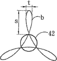
The visual user demand adjustment of the height of aforementioned application of force axle 51, be mainly used in engine as the present invention, this application of force axle 51 is near contact points 9 positions, to produce trajectory a as Figure 10, the supercharging track section s stroke of this trajectory a is longer, can provide fuller thrust, and skew track section t is narrower, can reduce the loss of cross component force, and for example shown in Figure 11 application of force axle 51 is highly turned down, form the trajectory b as Figure 12, the supercharging track section s stroke of this trajectory b is shorter, so linear thrust is also lower, and skew track section t broad, make piston 7 have part can form cross component force and loss, cause usefulness to reduce, be more inapplicable structure through the power of connecting rod 6.
In addition, via the aforementioned kinetic energy generating apparatus of finishing of the present invention, be mainly used in the engine, otherwise, the present invention also can promote gearing shaft 42 rotations by other power plant, again with power via axle center gear 31, free gear 3, flywheel 5, application of force axle 51, connecting rod 6, carry out energy storage by piston 7 compression cylinders at last, promptly be applied in the air compressor structure, this air compressor is used as shown in figure 13, need heighten application of force axle 51 height, form trajectory c, allow kinetic energy must fail back piston 7 and compress the output energy as Figure 14.Again, number of cylinders of the present invention if reduce its quantity, descends its sense of equilibrium with the design of three multiple amount, then can produce vibrating effect, also can be applicable in the structure such as massage chair.
See also Figure 15, shown in Figure 16, cylinder of the present invention with and piston 7, connecting rod 6 with three multiple setting, as six graphic cylinder structures, can be distributed into two groups of symmetries and rotate 180 ° of angles and be arranged on casing 1 two ends, and make symmetrical cylinder carry out identical stroke, use balance and double strength rotary moveable gear 3; Or as shown in figure 17, for nine cylinders configurations, can be at the same direction three-bank cylinders that be arranged in parallel, each activity of organizing cylinder differs a stroke, so can increase by three times torsion.
Above-listed detailed description is at the specifying of a kind of possible embodiments of the present invention, but is not to realize sole mode of the present invention.
Claims (8)
1. kinetic energy generating apparatus, it comprises a casing, one fixed gear, one free gear, one driving component, one flywheel and several connecting rods, it is characterized in that: this fixing tooth train is arranged on the casing inner edge, this free gear is then engageable to rotate on fixed gear, this fixed gear is 3: 2 with the gear ratio of free gear, it is inner and rotatable that this driving component system is arranged on casing, this driving component shaft core position then is provided with a gearing shaft, free gear is provided with an axle center gear relatively, make this axle center gear engagement on gearing shaft, this gearing shaft is 3: 2 with the gear of axle center gear than also, this flywheel is fixedly connected on the gear outside, axle center, this flywheel one end is provided with application of force axle, this connecting rod then axle is located on the application of force axle, each connecting rod removes an end axle and is located on the flywheel application of force axle, and its other end then axle is located on the piston of cylinder.
2. by the described kinetic energy generating apparatus of claim 1, it is characterized in that: wherein this number of cylinders is three multiple, and is one group with per three and is arranged side by side, and three cylinders of each group are 120 ° angle configurations mutually.
3. by the described kinetic energy generating apparatus of claim 1, it is characterized in that: wherein this number of cylinders is six multiple, and be one group with per three cylinders, three cylinders of each group are 120 ° angle mutually, and three cylinders of another group are symmetry and rotate 180 ° and be arranged on the casing the other end then.
4. by the described kinetic energy generating apparatus of claim 1, it is characterized in that: wherein this driving component and casing surface of contact are provided with ball bearing in order to rotation.
5. by the described kinetic energy generating apparatus of claim 1, it is characterized in that: wherein the visual demand that is applied in engine or air compressor of the height of this application of force axle is adjusted its height.
6. by the described kinetic energy generating apparatus of claim 1, it is characterized in that: when wherein this piston is positioned at the stroke initial point, this axle center gear deflection in advance one angle.
7. by the described kinetic energy generating apparatus of claim 1, it is characterized in that: wherein the idle zone between this gearing shaft and the fixed gear is provided with driven gear.
8. by the described kinetic energy generating apparatus of claim 1, it is characterized in that: wherein this gearing shaft promotes rotation by other power plant, again with power via axle center gear, free gear, flywheel, application of force axle, connecting rod, carry out energy storage by the Piston Compression cylinder at last, use as air compressor.
Applications Claiming Priority (1)
| Application Number | Priority Date | Filing Date | Title |
|---|---|---|---|
| PCT/CN2005/000992 WO2007006170A1 (en) | 2005-07-07 | 2005-07-07 | Kinetic energy generation device |
Publications (2)
| Publication Number | Publication Date |
|---|---|
| CN101208503A CN101208503A (en) | 2008-06-25 |
| CN100572774C true CN100572774C (en) | 2009-12-23 |
Family
ID=37636720
Family Applications (1)
| Application Number | Title | Priority Date | Filing Date |
|---|---|---|---|
| CNB2005800502721A Expired - Fee Related CN100572774C (en) | 2005-07-07 | 2005-07-07 | Kinetic energy generating apparatus |
Country Status (12)
| Country | Link |
|---|---|
| US (1) | US7926462B2 (en) |
| EP (1) | EP1905983B1 (en) |
| JP (1) | JP2008545079A (en) |
| KR (1) | KR101018243B1 (en) |
| CN (1) | CN100572774C (en) |
| AT (1) | ATE524644T1 (en) |
| AU (1) | AU2005334426B2 (en) |
| BR (1) | BRPI0520398A2 (en) |
| CA (1) | CA2613989A1 (en) |
| EG (1) | EG24971A (en) |
| MX (1) | MX2008000036A (en) |
| WO (1) | WO2007006170A1 (en) |
Cited By (1)
| Publication number | Priority date | Publication date | Assignee | Title |
|---|---|---|---|---|
| CN105626453A (en) * | 2016-03-04 | 2016-06-01 | 安徽工程大学 | Piston compressor and movement inertia force balancing method for piston compressor |
Families Citing this family (6)
| Publication number | Priority date | Publication date | Assignee | Title |
|---|---|---|---|---|
| US8001948B2 (en) | 2008-01-30 | 2011-08-23 | Chuy-Nan Chio | Kinetic energy generation apparatus having increased power output |
| ES2369448B1 (en) * | 2008-12-19 | 2012-09-18 | Universidad De Sevilla | CONTINUOUSLY VARIABLE TRANSMISSION SYSTEM. |
| DE102013225147A1 (en) | 2013-12-06 | 2015-06-11 | Baustoffwerke Gebhart & Söhne GmbH & Co. KG | Constant volume combustion engine |
| CN104405504B (en) * | 2014-12-10 | 2017-12-15 | 刘小木 | A kind of piston type four-stroke internal combustion engine for having two bent axles |
| JP2016205425A (en) * | 2015-04-16 | 2016-12-08 | ハイブリッドエナジー株式会社 | Power transmission device |
| CN108661872A (en) * | 2018-05-08 | 2018-10-16 | 伊书娥 | A kind of intelligence barreled water taker |
Family Cites Families (12)
| Publication number | Priority date | Publication date | Assignee | Title |
|---|---|---|---|---|
| DE3233314A1 (en) * | 1982-09-08 | 1984-03-08 | Anton 8451 Haselmühl Lehr | Internal combustion engine |
| EP0309508B1 (en) * | 1987-04-13 | 1990-12-27 | FREY, Heinz | Crank mechanism |
| US5158047A (en) * | 1990-05-14 | 1992-10-27 | Schaal Jack E | Delayed drop power stroke internal combustion engine |
| JPH0626359A (en) * | 1992-06-23 | 1994-02-01 | Munemitsu Ise | Internal combustion engine |
| JPH0763066A (en) * | 1993-08-26 | 1995-03-07 | Toyo Commun Equip Co Ltd | Reciprocating engine |
| CN1116685A (en) * | 1994-08-08 | 1996-02-14 | 钱兴玉 | Reciprocating piston type internal combustion power mechanism |
| JP2000515213A (en) * | 1996-01-19 | 2000-11-14 | ラファエル、ピーター、ロバート | Three-cycle engine |
| CN1104554C (en) * | 1997-07-15 | 2003-04-02 | 新动力概念有限公司 | Cantilever crank stirling cycle machine set |
| US6484687B1 (en) * | 2001-05-07 | 2002-11-26 | Saddle Rock Technologies Llc | Rotary machine and thermal cycle |
| DE10206144A1 (en) * | 2001-11-07 | 2003-09-04 | Marjan Miler | transmission |
| EP1509708B1 (en) * | 2002-05-31 | 2006-10-25 | Klaus Plath | Transmission device comprising an eccentric power transmission axle that is disposed on the bearing axle |
| DE10353873B4 (en) * | 2003-11-18 | 2006-05-11 | Kropp, Jürgen Werner | Reciprocating engine with rotating crankshaft |
-
2005
- 2005-07-07 BR BRPI0520398-8A patent/BRPI0520398A2/en not_active IP Right Cessation
- 2005-07-07 US US11/994,493 patent/US7926462B2/en not_active Expired - Fee Related
- 2005-07-07 WO PCT/CN2005/000992 patent/WO2007006170A1/en active Application Filing
- 2005-07-07 CA CA002613989A patent/CA2613989A1/en not_active Abandoned
- 2005-07-07 JP JP2008518593A patent/JP2008545079A/en active Pending
- 2005-07-07 CN CNB2005800502721A patent/CN100572774C/en not_active Expired - Fee Related
- 2005-07-07 KR KR1020087001113A patent/KR101018243B1/en not_active IP Right Cessation
- 2005-07-07 MX MX2008000036A patent/MX2008000036A/en active IP Right Grant
- 2005-07-07 AU AU2005334426A patent/AU2005334426B2/en not_active Ceased
- 2005-07-07 AT AT05762247T patent/ATE524644T1/en not_active IP Right Cessation
- 2005-07-07 EP EP05762247A patent/EP1905983B1/en not_active Not-in-force
-
2008
- 2008-01-03 EG EG2008010007A patent/EG24971A/en active
Cited By (1)
| Publication number | Priority date | Publication date | Assignee | Title |
|---|---|---|---|---|
| CN105626453A (en) * | 2016-03-04 | 2016-06-01 | 安徽工程大学 | Piston compressor and movement inertia force balancing method for piston compressor |
Also Published As
| Publication number | Publication date |
|---|---|
| EP1905983A1 (en) | 2008-04-02 |
| US20080210026A1 (en) | 2008-09-04 |
| KR20080015518A (en) | 2008-02-19 |
| AU2005334426B2 (en) | 2013-05-16 |
| CN101208503A (en) | 2008-06-25 |
| MX2008000036A (en) | 2008-03-19 |
| EP1905983B1 (en) | 2011-09-14 |
| AU2005334426A1 (en) | 2007-01-18 |
| WO2007006170A1 (en) | 2007-01-18 |
| EG24971A (en) | 2011-03-23 |
| KR101018243B1 (en) | 2011-03-03 |
| US7926462B2 (en) | 2011-04-19 |
| JP2008545079A (en) | 2008-12-11 |
| CA2613989A1 (en) | 2007-01-18 |
| BRPI0520398A2 (en) | 2009-05-05 |
| ATE524644T1 (en) | 2011-09-15 |
| EP1905983A4 (en) | 2009-08-12 |
Similar Documents
| Publication | Publication Date | Title |
|---|---|---|
| CN100572774C (en) | Kinetic energy generating apparatus | |
| CN101709671B (en) | Symmetrical rocker type large-torque output engine | |
| US8001948B2 (en) | Kinetic energy generation apparatus having increased power output | |
| JPH05508208A (en) | crank mechanism | |
| CN108757172A (en) | A kind of half gear engine of four cylinders linkage | |
| CN201723303U (en) | Planetary rotary-combustion engine | |
| RU2349813C1 (en) | Two-shaft connecting rod gear | |
| RU2096638C1 (en) | Piston-type machine (options) | |
| CN101463733B (en) | Kinetic energy generation apparatus with improved output power | |
| CN2249333Y (en) | Sleeve piston driving device | |
| CN100494653C (en) | Butt-jointing technological method for piston or cylinder and composite piston | |
| CN85109318A (en) | The beater mechanism that rotation function is directly changed | |
| JP2530951B2 (en) | Oldham drive engine | |
| WO2009009925A1 (en) | A kinetic energy generation apparatus having increased power energy | |
| CN107620634A (en) | A kind of rotary combustion engine | |
| TWI326737B (en) | ||
| WO2008022489A1 (en) | Kinetic energy transmission apparatus | |
| TW200923197A (en) | Kinetic energy generation device for increasing output power | |
| RU2388918C2 (en) | Kinetic energy generation device | |
| RU67649U1 (en) | INTERNAL COMBUSTION ENGINE | |
| CN103343714B (en) | Reciprocating piston engine with elliptical cams | |
| CN101886572B (en) | Planetary rotary internal combustion engine | |
| RU29963U1 (en) | Impulsive internal combustion engine | |
| RU2228453C1 (en) | Internal combustion engine | |
| RU52928U1 (en) | ROTATION TRANSMISSION DEVICE |
Legal Events
| Date | Code | Title | Description |
|---|---|---|---|
| C06 | Publication | ||
| PB01 | Publication | ||
| C10 | Entry into substantive examination | ||
| SE01 | Entry into force of request for substantive examination | ||
| C14 | Grant of patent or utility model | ||
| GR01 | Patent grant | ||
| CF01 | Termination of patent right due to non-payment of annual fee |
Granted publication date: 20091223 Termination date: 20160707 |
|
| CF01 | Termination of patent right due to non-payment of annual fee |