CN100559107C - Heat-exchange device and have the internal combustion engine of this device - Google Patents
Heat-exchange device and have the internal combustion engine of this device Download PDFInfo
- Publication number
- CN100559107C CN100559107C CNB2003801091845A CN200380109184A CN100559107C CN 100559107 C CN100559107 C CN 100559107C CN B2003801091845 A CNB2003801091845 A CN B2003801091845A CN 200380109184 A CN200380109184 A CN 200380109184A CN 100559107 C CN100559107 C CN 100559107C
- Authority
- CN
- China
- Prior art keywords
- heat
- exchange device
- medium
- housing
- outlet
- Prior art date
- Legal status (The legal status is an assumption and is not a legal conclusion. Google has not performed a legal analysis and makes no representation as to the accuracy of the status listed.)
- Expired - Fee Related
Links
- 238000002485 combustion reaction Methods 0.000 title claims abstract description 55
- 238000001816 cooling Methods 0.000 claims abstract description 8
- 230000008676 import Effects 0.000 claims description 45
- 239000007788 liquid Substances 0.000 claims description 12
- 239000000463 material Substances 0.000 claims description 8
- 230000001154 acute effect Effects 0.000 claims description 7
- XEEYBQQBJWHFJM-UHFFFAOYSA-N Iron Chemical compound [Fe] XEEYBQQBJWHFJM-UHFFFAOYSA-N 0.000 claims description 4
- 238000005476 soldering Methods 0.000 claims description 4
- 229910000838 Al alloy Inorganic materials 0.000 claims description 2
- 229910001369 Brass Inorganic materials 0.000 claims description 2
- RYGMFSIKBFXOCR-UHFFFAOYSA-N Copper Chemical compound [Cu] RYGMFSIKBFXOCR-UHFFFAOYSA-N 0.000 claims description 2
- 229910001021 Ferroalloy Inorganic materials 0.000 claims description 2
- 229920002430 Fibre-reinforced plastic Polymers 0.000 claims description 2
- 239000004411 aluminium Substances 0.000 claims description 2
- 229910052782 aluminium Inorganic materials 0.000 claims description 2
- XAGFODPZIPBFFR-UHFFFAOYSA-N aluminium Chemical compound [Al] XAGFODPZIPBFFR-UHFFFAOYSA-N 0.000 claims description 2
- 239000010951 brass Substances 0.000 claims description 2
- 239000010949 copper Substances 0.000 claims description 2
- 229910052802 copper Inorganic materials 0.000 claims description 2
- 230000009977 dual effect Effects 0.000 claims description 2
- 239000011151 fibre-reinforced plastic Substances 0.000 claims description 2
- 229910052742 iron Inorganic materials 0.000 claims description 2
- 239000002184 metal Substances 0.000 claims description 2
- 229910052751 metal Inorganic materials 0.000 claims description 2
- 229910001092 metal group alloy Inorganic materials 0.000 claims description 2
- 239000004033 plastic Substances 0.000 claims description 2
- 229920003023 plastic Polymers 0.000 claims description 2
- 229920001187 thermosetting polymer Polymers 0.000 claims description 2
- RTAQQCXQSZGOHL-UHFFFAOYSA-N Titanium Chemical compound [Ti] RTAQQCXQSZGOHL-UHFFFAOYSA-N 0.000 claims 1
- 238000007789 sealing Methods 0.000 claims 1
- 239000010936 titanium Substances 0.000 claims 1
- 229910052719 titanium Inorganic materials 0.000 claims 1
- LYCAIKOWRPUZTN-UHFFFAOYSA-N Ethylene glycol Chemical compound OCCO LYCAIKOWRPUZTN-UHFFFAOYSA-N 0.000 description 6
- 239000007789 gas Substances 0.000 description 4
- 238000000034 method Methods 0.000 description 4
- XLYOFNOQVPJJNP-UHFFFAOYSA-N water Substances O XLYOFNOQVPJJNP-UHFFFAOYSA-N 0.000 description 4
- 238000010586 diagram Methods 0.000 description 3
- 238000004519 manufacturing process Methods 0.000 description 3
- 239000012071 phase Substances 0.000 description 3
- 239000003507 refrigerant Substances 0.000 description 3
- 230000002159 abnormal effect Effects 0.000 description 2
- 239000000654 additive Substances 0.000 description 2
- 230000000996 additive effect Effects 0.000 description 2
- 230000000694 effects Effects 0.000 description 2
- 238000009434 installation Methods 0.000 description 2
- 239000007791 liquid phase Substances 0.000 description 2
- 230000009471 action Effects 0.000 description 1
- 230000008901 benefit Effects 0.000 description 1
- 230000005540 biological transmission Effects 0.000 description 1
- 230000008859 change Effects 0.000 description 1
- 239000012809 cooling fluid Substances 0.000 description 1
- 238000006073 displacement reaction Methods 0.000 description 1
- 230000006872 improvement Effects 0.000 description 1
- 230000003447 ipsilateral effect Effects 0.000 description 1
- 150000002739 metals Chemical class 0.000 description 1
- 238000005325 percolation Methods 0.000 description 1
- 230000008569 process Effects 0.000 description 1
- 239000002912 waste gas Substances 0.000 description 1
Images


Classifications
-
- F—MECHANICAL ENGINEERING; LIGHTING; HEATING; WEAPONS; BLASTING
- F28—HEAT EXCHANGE IN GENERAL
- F28F—DETAILS OF HEAT-EXCHANGE AND HEAT-TRANSFER APPARATUS, OF GENERAL APPLICATION
- F28F9/00—Casings; Header boxes; Auxiliary supports for elements; Auxiliary members within casings
- F28F9/02—Header boxes; End plates
-
- F—MECHANICAL ENGINEERING; LIGHTING; HEATING; WEAPONS; BLASTING
- F28—HEAT EXCHANGE IN GENERAL
- F28D—HEAT-EXCHANGE APPARATUS, NOT PROVIDED FOR IN ANOTHER SUBCLASS, IN WHICH THE HEAT-EXCHANGE MEDIA DO NOT COME INTO DIRECT CONTACT
- F28D7/00—Heat-exchange apparatus having stationary tubular conduit assemblies for both heat-exchange media, the media being in contact with different sides of a conduit wall
- F28D7/16—Heat-exchange apparatus having stationary tubular conduit assemblies for both heat-exchange media, the media being in contact with different sides of a conduit wall the conduits being arranged in parallel spaced relation
- F28D7/1684—Heat-exchange apparatus having stationary tubular conduit assemblies for both heat-exchange media, the media being in contact with different sides of a conduit wall the conduits being arranged in parallel spaced relation the conduits having a non-circular cross-section
-
- F—MECHANICAL ENGINEERING; LIGHTING; HEATING; WEAPONS; BLASTING
- F28—HEAT EXCHANGE IN GENERAL
- F28F—DETAILS OF HEAT-EXCHANGE AND HEAT-TRANSFER APPARATUS, OF GENERAL APPLICATION
- F28F9/00—Casings; Header boxes; Auxiliary supports for elements; Auxiliary members within casings
- F28F9/001—Casings in the form of plate-like arrangements; Frames enclosing a heat exchange core
-
- F—MECHANICAL ENGINEERING; LIGHTING; HEATING; WEAPONS; BLASTING
- F28—HEAT EXCHANGE IN GENERAL
- F28D—HEAT-EXCHANGE APPARATUS, NOT PROVIDED FOR IN ANOTHER SUBCLASS, IN WHICH THE HEAT-EXCHANGE MEDIA DO NOT COME INTO DIRECT CONTACT
- F28D21/00—Heat-exchange apparatus not covered by any of the groups F28D1/00 - F28D20/00
- F28D21/0001—Recuperative heat exchangers
- F28D21/0003—Recuperative heat exchangers the heat being recuperated from exhaust gases
Abstract
The invention discloses a kind of heat-exchange device and have the internal combustion engine of this device, cooling especially for the combustion air of car combustion engine, it is characterized in that, flow-through element is installed in one and is at least in the two-part section bar housing, wherein, the basic configuration in the cross section of first housing parts is a U-shaped, be essentially flat second housing parts then with one side closed live of opening wide on first housing parts, and housing has suction flange and at least one outlet(discharge) flange of at least one second kind of medium on two relative sides, and flow-through element is spaced from each other at least one zone by the frame element that at least one is installed in the housing.
Description
Technical field
The present invention relates to a kind of heat-exchange device and have the internal combustion engine of this device, be particularly useful for the cooling of the combustion air of car combustion engine.This heat-exchange device is also referred to as charger-air cooler, is used for the combustion air of cooling internal combustion engines.But the present invention also can be applicable on other the heat exchanger.
Background technology
Here, the air of the burning usefulness that temperature uprises passes this device owing to compress, and is flow through the refrigerant cools of this device equally.In German patent DE 19927607 disclosed devices, the air of burning usefulness passes heat-exchange device by some pipes, and this device has input pipe and the efferent duct that flows through for cold-producing medium, the then cooled dose circulation of pipe in the device.For guaranteeing the interval between each pipe so that cold-producing medium can therefrom flow through, under prior art, the end of pipe is extended, and each pipe just is spaced apart each other like this.
But this manufacture method has shortcoming, must very accurately aim at mutually between each pipe, and see that technically the integral braze-welded cost of device is very high.In addition, the housing of this device is made of two parts, and promptly it has body and top cover of a U-shaped, and top cover is inserted among the body.But this frame mode also has shortcoming, and top cover can be subjected to displacement with respect to body, can bring negative effect to the accuracy of manufacture like this.
Summary of the invention
Task of the present invention provides the heat-exchange device after a kind of the improvement and has the internal combustion engine of this device, and its manufacturing cost greatly reduces.
Of the present invention to liking a kind of heat-exchange device, be particularly useful for the cooling of the combustion air of car combustion engine.It has at least one import and the outlet of first kind of medium, and first kind of medium can be cold-producing medium, cooling fluid or other medium; It also has at least one import and the outlet of second kind of medium, and second kind of medium can be combustion air, waste gas or other medium.In addition, be provided with the flow-through element of at least one cold-producing medium and the flow-through element of at least one combustion air in the device, wherein, the stream in stream in the cold-producing medium flow-through element and the combustion air circulation element is separated mutually, and flow-through element is different at least on a part.
Flow-through element is meant a kind of device that flow media is spatially limited, for example pipe, particularly flat tube or similarly device.An element can have some parts.
In addition, flow-through element also can refer to two spaces between the object.If medium can flow in this space, it has just formed a stream.For example, the zone between two flat tubes is regarded as flow-through element.
Cold-producing medium typically refers to the medium of gas phase or liquid phase, and its temperature is lower than the medium that is cooled, as combustion air.Cold-producing medium is preferably considered water, and it may have especially ethylene glycol (Glykol) additive from cool cycles, and therefore cold-producing medium also is meant water hereinafter.
Stream is meant the glide path of a kind of medium in a flow-through element, for example cold-producing medium in device cooling combustion during with air in import with the route that is flow through between exporting.
Flow direction is meant that medium is cold-producing medium or combustion air surpass the certain hour scope at least in flow-through element a flow direction in order to make the combustion air cooling.
In addition, the invention is characterized in, flow-through element is installed in one and is at least two parts and has in the housing of certain special-shaped device (Profilierten), wherein, the basic configuration in the cross section of first housing parts is a U-shaped, is essentially flat second housing parts then with one side closed live of opening wide on first housing parts.
The housing of heat-exchange device has at least one combustion air suction flange and at least one combustion air outlet(discharge) flange on two relative sides.
By being installed at least one frame element in the housing, the flow-through element of combustion air and/or cold-producing medium is spaced from each other at least one zone.
Dimeric housing is meant that housing is not to be made by a body, but has two independent parts, and they are assembled together, and especially they interconnect.
Abnormal shape is meant that limit that each housing parts mutually combines is not to extend by straight line, but off-straight in some way.So just can on a housing parts otch or groove be set, the protuberance on second housing parts then is embedded into wherein.In addition, protuberance can be set to geometry arbitrarily, and it is embedded in the corresponding with it recess on corresponding another housing parts.
U-shaped basic configuration among the present invention is meant a kind of like this shape, and its cross section is essentially the rectangle that lacks four edges.Here, each angle also can become fillet, and perhaps a limit is rounded or oval.And the extension on each limit is also also nonessential along straight line.
In the present invention, the notion of " U-shaped " has also been described a kind of planform, and promptly in the cross section, that an is omitted limit is one side long in the rectangle.
At last, it has also comprised this shape: its cross section is essentially oval, and a section of this ellipse is cut off.
Flat housing parts is meant a housing parts that extends basically in bidimensional, that is to say, it is essentially a plane.
According to the present invention, frame element is meant an element that flow-through element is fixed by predetermined space.
In a preferred form of implementation, at least a portion of first housing parts has the import and the outlet of cold-producing medium.
The import of cold-producing medium and outlet preferably are arranged on the same side.Also the import of cold-producing medium and outlet can be arranged in not on the ipsilateral, be on the relative side especially.On housing, import with go out open height can be identical, also can be different.Can certainly adopt dual import and/or outlet.
In a form of implementation, the import of cold-producing medium and outlet are arranged near two angles of heat-exchange device, and these two angles then are positioned on the space diagonal of heat-exchange device.
The flow-through element of combustion air is preferably flat tube.Flat tube is a kind of like this pipe, and it has certain width, and it is highly then less than this width.The cross section of this flat tube can be rectangle, ellipse or analogous shape.Flat tube in the flow-through element of the combustion air layout that is parallel to each other substantially.
The flow-through element of cold-producing medium preferably has turbulent element, for example turbulent grid or turbulence plate, structure plate, turbulator or the like.
The structure plate is meant surface irregularity, but has protuberance, groove, flange or a like, like this can enhanced flow through the turbulent flow of medium, thereby improve heat transmission between wall and the medium.
The flow-through element of cold-producing medium preferably has separator, and they have formed at least one refrigerant flow path of determining.This should only not be interpreted as that cold-producing medium just can not arrive outlet from import with the shortest circuit like this, but says that the effect of separator is, cold-producing medium is percolation in whole housing scope basically.This also can be understood as a kind of so-called forced flow.
The parts of heat-exchange device, as the suction flange of flow-through element, housing, refrigerant inlet and outlet, combustion air and outlet(discharge) flange etc., by at least a the making in following one group of material, this group material comprises as metals such as aluminium, iron, brass, copper, titaniums, as metal alloys such as aluminium alloy, ferroalloys, as plastics such as PVC, PU, thermosetting plastics, fibre reinforced plastics.
In a preferred form of implementation, first housing parts has formed a cuboid with three special-shaped sides basically, becomes the angle of a regulation between the direction of wherein special-shaped part and the main flow direction of combustion air.
A special-shaped side is meant that the side is not a smooth plane, but has the part that departs between predetermined and the flat surface.
Second housing parts preferably has the exterior contour that cooperates with the special-shaped profile phase of first housing parts.In this way, second housing parts just can accurately cooperate with the special-shaped formed surface by first housing parts.
In a preferred form of implementation, import and outlet(discharge) flange are made of two parts at least, they on two opposing end surfaces of rectangular-shaped housing, seal and form airtight and/or liquid close.Here, import and/or outlet(discharge) flange preferably have a body that processes shape through deep-draw, have a sleeve pipe (Durchfu ü hrung) in the body, and this sleeve pipe is inserted in a pipe, the distance of one section regulation of tube connector particularly, or this sleeve pipe is inserted into certain-length in this pipe.For this reason, the import or export flange can have a protrusion, and as flange, this can improve and being connected of another root pipe.
The import of cold-producing medium and outlet are preferably the sleeve pipe in the housing, are inserted in a segment distance predetermined on the pipe, particularly tube connector in this sleeve pipe, and perhaps this sleeve pipe is inserted into a segment length in this pipe.Here also protrusion or flange can be set in import, make the connection of tube connector become easy like this.
Second housing parts, limiting element and flange are preferably formed the housing end face airtight and/or liquid thickly seals.
Be provided with at least two frame elements in another preferred form of implementation, they make flat tube space in the flow-through element of combustion air and fixing.In this case, frame element preferably is arranged near the flat tube end.But also can consider other arrangement form of frame element, promptly frame element is simultaneously as separator, thereby cold-producing medium can be distributed in the entire inner space of cold-producing medium flow-through element basically.
Frame element is preferably a flat board, and it has the sleeve pipe of specified quantity in order to hold flat tube.The cross section of these sleeve pipes is consistent with the cross section of flat tube basically, or more bigger than the latter.
In a particularly preferred form of implementation, frame element and flat tube thickly interconnect by airtight and/or liquid.
In addition, the connection between the parts of heat-exchange device is preferably the connection of material fit, the connection of power cooperation and/or the connection of form fit.In a preferred form of implementation, link together by soldering between each parts of heat-exchange device.
In another preferred form of implementation, frame element is a flat board that the edge makes progress, and its edge especially is connected with at least one section of enclosure interior profile.But except the edge that makes progress, the edge of frame element also can be continuous, be acute angle or chamfering.
In addition, the invention still further relates to the internal combustion engine that has exhaust-driven turbo-charger exhaust-gas turbo charger or compressor, exhaust-driven turbo-charger exhaust-gas turbo charger or compressor have at least one heat-exchange device as described in the present invention.
The present invention also relates to a kind of heat change method in addition, in particular for the method for cooling as the combustion air of supercharging of internal combustion engine air, wherein, in a first step, temperature is article one stream that the combustion air of T1 enters into device of the present invention, and in second step, temperature is the second stream that the cold-producing medium of T2 enters into same device.In following step, between combustion air and the cold-producing medium exchange heat appears.At last, temperature is that the combustion air of T3 is output.In this course, temperature T 1 is higher than temperature T 3, and temperature T 3 is higher than temperature T 2.
Description of drawings
Below in conjunction with accompanying drawing other advantage of the present invention and structure are described in detail.Wherein:
Shown in Figure 1 is first form of implementation of heat-exchange device as described in the present invention;
Fig. 2 is the local device figure of heat-exchange device shown in Fig. 1;
Fig. 3 is the local part drawing of heat-exchange device shown in Fig. 1 and 2;
It among Fig. 4 the installation diagram of another form of implementation of heat-exchange device as described in the present invention;
Fig. 5 is the partial exploded view of heat-exchange device of the present invention as shown in Figure 4;
Fig. 6 is another exploded view of heat-exchange device of the present invention as shown in Figure 4;
Fig. 7 is the local device figure of heat-exchange device of the present invention as shown in Figure 4;
Fig. 8 is the local part drawing of the heat-exchange device of the present invention as shown in Fig. 4 to 7;
It among Fig. 9 the installation diagram of another form of implementation of heat-exchange device as described in the present invention;
Figure 10 is the partial exploded view of heat-exchange device of the present invention as shown in Figure 9;
Figure 11 is another view of heat-exchange device shown in Figure 10;
Figure 12 is the local device figure of heat-exchange device shown in Fig. 9;
Figure 13 is the local part drawing of heat-exchange device shown in Fig. 9 to 12.
The specific embodiment
Fig. 1 is a partial exploded view of heat-exchange device as described in the present invention.Reference number 1 and 2 is meant the import and the outlet of cold-producing medium.
This cold-producing medium is preferably water, is meant from cool cycles especially and has for example water of the additive of ethylene glycol.But also can be that other not only is a gas phase but also be the cold-producing medium of liquid phase.
In this form of implementation, housing is made up of first part 6a, and this part is essentially U-shaped.In Fig. 1, a side of opening wide on the U-shaped is towards the direction of arrow A indication.In addition, housing also has second part 6b, and it here is a cover plate, and it lives a side cover that is open upwards in the first that takes the shape of the letter U.
The first that takes the shape of the letter U has and has corresponding special-shaped section on 13, the second parts of special-shaped section and cooperate with it.
In Fig. 1, second housing parts 6b is rectangular basically, and a recessed section is arranged on its that long side.
Fig. 2 is the local device figure of heat-exchange device shown in Fig. 1.Reference number 1a and 2a are meant flange, and the import 1 and the outlet 2 of cold-producing medium can be inserted in this flange.Reference number 6a also is meant the first that takes the shape of the letter U of housing, and it structurally is a section bar.Second part, promptly the cover plate of housing is removed in this figure.Reference number 12 also is meant frame element.
Fig. 3 is another part drawing, and it has showed the internal structure of the housing 6 of heat-exchange device shown in Fig. 1.Arranging flat tube 14 within housing 6, the air of burning usefulness passes among them.Between each flat tube, arranging special-shaped plate 15.
That so-called abnormal shape is meant is recessed, protuberance, groove and similar shape.Special-shaped device 15 is preferably turbulent element, as turbulent grid or turbulence plate, structure plate, turbulator or similar device.
In when operation, pass import 1 from the cold-producing medium of cool cycles and enter into device, here, cold-producing medium arbitrarily distributes in the whole volume scope of housing basically, and special-shaped plate 15 has then improved the heat exchange with flat tube.At last, cold-producing medium flows out from device by outlet 2 again.
Here, the top cover that has combustion air import place has edge 5a and 5b on three sides, and wherein, the 3rd side is positioned at the direction of the back of the body towards the observer.On the 4th side, the ledge 6c of housing 6b is inserted in the top cover 5.
Be another form of implementation of heat-exchange device as described in the present invention among Fig. 4, here it is a confined state.Reference number 1 and 2 also is meant the import and the outlet of cold-producing medium.Reference number 3 and 4 refers to the import and the outlet of combustion air.Arrow is meant the flow direction of combustion air and cold-producing medium respectively.Housing also is to have a 6a of first that takes the shape of the letter U and a second portion is cover plate 6b '.Different with form of implementation among Fig. 1 is that cover plate exceeds the first that takes the shape of the letter U along side direction, does not just have nose section 6c here.
Fig. 5 is the partial exploded view of heat-exchange device shown in Fig. 4.As can be seen from the figure, second part, promptly cover plate 6b ' is in equal height place and first part 6a closure.Different with the top cover 5 at combustion air outlet place is, the top cover 5 ' at combustion air outlet place has outstanding edge 5a ', 5b ', 5c ', 5d ' (5c ' and 5d ' not shown in the diagram) four side edge.
Fig. 6 is the exploded view of heat-exchange device shown in Fig. 4.As can be seen from the figure, flat tube 14 runs through frame element 12.Second part of housing, i.e. cover plate 6b also has special-shaped section, it with first part 6a of housing on corresponding special-shaped section match.Under confined state, top cover 5 ' is enclosed on the framework 12.The top cover at the top cover at the import place of combustion air and the outlet place of combustion air preferably adopts identical shape.
Fig. 7 is the part drawing of heat-exchange device shown in Fig. 6.Second housing parts 6b is removed, so that can see the inside of housing.
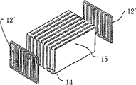
Fig. 8 is another part drawing of heat-exchange device.Here, the type of flow of cold-producing medium and first form of implementation are similar, thereby no longer describe in detail here.Different with the frame element in first form of implementation is not have the edge on the frame element 12 ', but be essentially two-dimensional structure.And also being provided with device 15 in this embodiment, it is called as turbulator below.
But can stay free space between each flat tube yet, and not arrange turbulator, like this, cold-producing medium does not flow between them with just can not stopped basically.In above-mentioned form of implementation, the design of heat-exchange device that is to say that based on countercurrent action the import of cold-producing medium and the outlet of combustion air are in the same side, and the outlet of cold-producing medium and the import of combustion air are in the same side.But also can be with import and the import of outlet or combustion air and the place-exchange of outlet of cold-producing medium.
The length of heat-exchange device especially between 100mm and 600mm, is preferably 150mm between the 500mm between 50mm and 600mm, again and then be preferably between 200mm and the 400mm.The height of flat tube especially between 4mm and 10mm, is preferably between 7.5mm and the 8.5mm between 2mm and 40mm.
It among Figure 10 another form of implementation of heat-exchange device of the present invention.The fundamental difference of it and foregoing form of implementation is that second housing parts 6b ' is cover plate and top cover 5 " structure.Top cover 5 " simple shape, only have two sidewall 5a and 5b.Second part 6b ' of housing is inserted in the middle hole between sidewall 5a and the 5b.
Figure 11 is the view of the heat-exchange device shown in Figure 10 in another angle.Because top cover 5 " only have two sidewalls, and second part 6b ' of housing only replaced a sidewall, so need a device with remaining closure of openings.This realizes by a thin plate 7 that is inserted into last side-walls.And the top cover at import 3 places of combustion air also adopts identical structure.Here will should be mentioned that, though two top covers of the import of combustion air and outlet adopt identical structure here, be not to do like this.Thereby also the top cover of the different structure in the different forms of implementation can be made up mutually.
It among Fig. 9 the confined state of the 3rd form of implementation of heat-exchange device of the present invention.
Figure 12 is the part drawing of the 3rd form of implementation of heat-exchange device of the present invention.As Figure 12 and shown in Figure 13, the end of each flat tube 14 is inserted among frame element 12 and the 12a.
Claims (50)
1. heat-exchange device, be used for the cooling of the combustion air of car combustion engine, it has at least one import and an outlet of the first kind of medium that comprises cold-producing medium, and at least one import and an outlet of comprising second kind of medium of combustion air, at least one flow-through element and at least one flow-through element that comprises second kind of medium of combustion air of also having the first kind of medium that comprises cold-producing medium, wherein, the stream that is used for the flow-through element of first kind of medium is separated mutually with the stream that is used for the flow-through element of second kind of medium, and flow-through element is inequality on a part at least, it is characterized in that, the flow-through element of the flow-through element of described first kind of medium and second kind of medium is installed in one and is at least in the two-part section bar housing, wherein, the cross section of first housing parts be shaped as U-shaped, be that flat second housing parts is then with one side closed live of opening wide on first housing parts, and housing has suction flange and at least one outlet(discharge) flange of at least one second kind of medium on two relative sides, and flow-through element is spaced from each other at least one zone by the frame element that at least one is installed in the housing; The import and the outlet that comprise first kind of medium of cold-producing medium are arranged on the same side of housing.
2. heat-exchange device as claimed in claim 1 is characterized in that, at least a portion of first housing parts has the import and the outlet of first kind of medium.
3. heat-exchange device as claimed in claim 1 is characterized in that, comprises that first kind of medium of cold-producing medium has single or dual import and/or outlet.
4. heat-exchange device as claimed in claim 1 is characterized in that, the flow-through element that comprises second kind of medium of combustion air is a flat tube.
5. heat-exchange device as claimed in claim 4 is characterized in that, the described flat tube layout that is parallel to each other.
6. heat-exchange device as claimed in claim 4 is characterized in that, flat tube is arranged to row, two row or multiple row parallel pipes, wherein, and the parallel with one another and/or arranged in series of each row flat tube.
7. heat-exchange device as claimed in claim 4 is characterized in that, the number of tubes in each row flat tube pre-determines quantity.
8. heat-exchange device as claimed in claim 4 is characterized in that, comprises that the flow-through element of first kind of medium of cold-producing medium has the turbulent element that comprises turbulent grid, turbulence plate, structure plate, turbulator.
9. heat-exchange device as claimed in claim 8 is characterized in that, in turbulent element area, the pressure drop on the main flow direction is greater than the pressure drop on the direction vertical with main flow direction.
10. heat-exchange device as claimed in claim 8 is characterized in that, comprises the stream that flow-through element had of first kind of medium of cold-producing medium, by distance and/or the decision of turbulent element to housing of the distance between the flat tube of combustion air and/or flat tube.
11. heat-exchange device as claimed in claim 1 is characterized in that, comprises that the flow-through element of first kind of medium of cold-producing medium has separator, they have determined that at least one is the stream that first kind of medium is provided with.
12. heat-exchange device as claimed in claim 1, it is characterized in that, the suction flange and the outlet(discharge) flange of the import of the flow-through element of this device, housing, first kind of medium and outlet, second kind of medium, by at least a the making in following one group of material, this group material comprise have aluminium, the metal of iron, brass, copper, titanium, metal alloy with aluminium alloy, ferroalloy has the plastics of PVC, PU, thermosetting plastics, fibre reinforced plastics.
13. heat-exchange device as claimed in claim 1 is characterized in that, first housing parts has formed a cuboid with three special-shaped sides, becomes a predetermined angle between the direction of wherein special-shaped part and the main flow direction of second kind of medium.
14. heat-exchange device as claimed in claim 1 is characterized in that, second housing parts has the exterior contour that cooperates with the special-shaped profile phase of first housing parts.
15. heat-exchange device as claimed in claim 1 is characterized in that, import and outlet(discharge) flange are made of two parts at least, and on two opposing end surfaces of cuboid the sealing and form airtight and/or liquid close.
16. as claim 4 or 5 or 6 or 7 or 8 or 9 or 10 described heat-exchange devices, it is characterized in that, import and/or outlet(discharge) flange have a body that forms through deep-draw processing, it has a sleeve pipe, and this sleeve pipe is inserted in the one section predetermined distance of a pipe that comprises tube connector, or this sleeve pipe is inserted into a segment length in this section pipe.
17. as the described heat-exchange device of arbitrary claim in the claim 1 to 15, it is characterized in that, the import of first kind of medium and outlet are the sleeve pipes on the housing, this sleeve pipe is inserted in the one section predetermined distance of a pipe that comprises tube connector, or this sleeve pipe is inserted into a segment length in this section pipe.
18. heat-exchange device as claimed in claim 16, it is characterized in that, the import of first kind of medium and outlet are the sleeve pipes on the housing, and this sleeve pipe is inserted in the one section predetermined distance of a pipe that comprises tube connector, or this sleeve pipe is inserted into a segment length in this section pipe.
19. as claim 4 or 5 or 6 or 7 or 8 or 9 or 10 described heat-exchange devices, it is characterized in that, import and/or outlet(discharge) flange have one and bend to body U-shaped, that have a sleeve pipe to both sides at least, and this sleeve pipe is inserted in the one section predetermined distance of a pipe that comprises tube connector, or this sleeve pipe is inserted into a segment length in this section pipe, and body also has the sleeve pipe that another is used for installing a limiting element.
20. heat-exchange device as claimed in claim 16, it is characterized in that, import and/or outlet(discharge) flange have one and bend to body U-shaped, that have a sleeve pipe to both sides at least, and this sleeve pipe is inserted in the one section predetermined distance of a pipe that comprises tube connector, or this sleeve pipe is inserted into a segment length in this section pipe, and body also has the sleeve pipe that another is used for installing a limiting element.
21. heat-exchange device as claimed in claim 20 is characterized in that, second housing parts, limiting element and flange form the housing end face airtight and/or liquid thickly seals.
22. heat-exchange device as claimed in claim 20 is characterized in that, second housing parts, limiting element and flange form the housing end face airtight and/or liquid thickly seals.
23. heat-exchange device as claimed in claim 20 is characterized in that, second housing parts, limiting element and flange form the housing end face airtight and/or liquid thickly seals.
24. heat-exchange device as claimed in claim 19 is characterized in that, second housing parts, limiting element and flange form the housing end face airtight and/or liquid thickly seals.
25. heat-exchange device as claimed in claim 20 is characterized in that, second housing parts, limiting element and flange form the housing end face airtight and/or liquid thickly seals.
26. as the described heat-exchange device of arbitrary claim in the claim 4 to 10, it is characterized in that this device has at least two frame elements, they make described flat tube space and fixing at least.
27. heat-exchange device as claimed in claim 16 is characterized in that, this device has at least two frame elements, and their described at least flat tube spaces are also fixing.
28. heat-exchange device as claimed in claim 19 is characterized in that, this device has at least two frame elements, and they make flat tube space in the flow-through element of second kind of medium and fixing at least.
29., it is characterized in that frame element is a smooth plate shape as claim 4 or 5 or 6 or 7 or 8 or 9 or 10 described heat-exchange devices, it has the sleeve pipe of specified quantity in order to hold flat tube.
30. heat-exchange device as claimed in claim 16 is characterized in that, frame element is a smooth plate shape, and it has the sleeve pipe of specified quantity in order to hold flat tube.
31. heat-exchange device as claimed in claim 19 is characterized in that, frame element is a smooth plate shape, and it has the sleeve pipe of specified quantity in order to hold flat tube.
32., it is characterized in that the airtight and/or liquid of frame element and flat tube thickly links together as the described heat-exchange device of arbitrary claim in the claim 4 to 10.
33. heat-exchange device as claimed in claim 16 is characterized in that, the airtight and/or liquid of frame element and flat tube thickly links together.
34. heat-exchange device as claimed in claim 19 is characterized in that, the airtight and/or liquid of frame element and flat tube thickly links together.
35. as the described heat-exchange device of arbitrary claim in the claim 1 to 15, it is characterized in that, be defined as the connection of material fit, the connection of power cooperation and/or the connection of form fit between the parts of this device.
36. heat-exchange device as claimed in claim 16 is characterized in that, is defined as the connection of material fit, the connection of power cooperation and/or the connection of form fit between the parts of this device.
37. heat-exchange device as claimed in claim 19 is characterized in that, is defined as the connection of material fit, the connection of power cooperation and/or the connection of form fit between the parts of this device.
38. as the described heat-exchange device of arbitrary claim in the claim 1 to 15, it is characterized in that, link together by soldering between each parts of heat-exchange device.
39. heat-exchange device as claimed in claim 16 is characterized in that, links together by soldering between each parts of heat-exchange device.
40. heat-exchange device as claimed in claim 19 is characterized in that, links together by soldering between each parts of heat-exchange device.
41., it is characterized in that frame element is a flat board that the edge makes progress as the described heat-exchange device of arbitrary claim in the claim 1 to 15, at least one section of its edge and enclosure interior profile is connected.
42. heat-exchange device as claimed in claim 16 is characterized in that, frame element is a flat board that the edge makes progress, and at least one section of its edge and enclosure interior profile is connected.
43. heat-exchange device as claimed in claim 19 is characterized in that, frame element is a flat board that the edge makes progress, and at least one section of its edge and enclosure interior profile is connected.
44., it is characterized in that the edge that makes progress of frame element has acute angle or chamfering as the described heat-exchange device of arbitrary claim in the claim 1 to 15.
45. heat-exchange device as claimed in claim 16 is characterized in that, the edge that makes progress of frame element has acute angle or chamfering.
46. heat-exchange device as claimed in claim 17 is characterized in that, the edge that makes progress of frame element has acute angle or chamfering.
47. heat-exchange device as claimed in claim 18 is characterized in that, the edge that makes progress of frame element has acute angle or chamfering.
48. heat-exchange device as claimed in claim 19 is characterized in that, the edge that makes progress of frame element has acute angle or chamfering.
49. heat-exchange device as claimed in claim 20 is characterized in that, the edge that makes progress of frame element has acute angle or chamfering.
50. have the internal combustion engine of an exhaust-driven turbo-charger exhaust-gas turbo charger, it is characterized in that it has at least one as the described heat-exchange device of one of claim 1 to 49.
Applications Claiming Priority (2)
| Application Number | Priority Date | Filing Date | Title |
|---|---|---|---|
| DE10302708.4 | 2003-01-23 | ||
| DE10302708A DE10302708A1 (en) | 2003-01-23 | 2003-01-23 | Device for exchanging heat used especially for cooling combustion air in IC engines of vehicles has flow units arranged in a two-part profiled housing |
Publications (2)
| Publication Number | Publication Date |
|---|---|
| CN1742188A CN1742188A (en) | 2006-03-01 |
| CN100559107C true CN100559107C (en) | 2009-11-11 |
Family
ID=32602919
Family Applications (1)
| Application Number | Title | Priority Date | Filing Date |
|---|---|---|---|
| CNB2003801091845A Expired - Fee Related CN100559107C (en) | 2003-01-23 | 2003-11-07 | Heat-exchange device and have the internal combustion engine of this device |
Country Status (9)
| Country | Link |
|---|---|
| US (1) | US7571718B2 (en) |
| EP (1) | EP1590615B1 (en) |
| JP (1) | JP4575169B2 (en) |
| CN (1) | CN100559107C (en) |
| AT (1) | ATE543064T1 (en) |
| AU (1) | AU2003293667A1 (en) |
| BR (1) | BR0318033A (en) |
| DE (2) | DE10302708A1 (en) |
| WO (1) | WO2004065874A1 (en) |
Families Citing this family (74)
| Publication number | Priority date | Publication date | Assignee | Title |
|---|---|---|---|---|
| DE10302708A1 (en) * | 2003-01-23 | 2004-07-29 | Behr Gmbh & Co. Kg | Device for exchanging heat used especially for cooling combustion air in IC engines of vehicles has flow units arranged in a two-part profiled housing |
| FR2854229A1 (en) * | 2003-04-25 | 2004-10-29 | Realisation Mecaniques Engenee | Heat exchanger for use in gas boiler, has primary and secondary heat exchanger arranged to transverse flow of hot air towards interstice of exchangers, and duct passing another flow of hot air into secondary exchanger |
| DE502004003357D1 (en) * | 2004-11-10 | 2007-05-10 | Modine Mfg Co | Heat exchanger with open profile as housing |
| JP4666142B2 (en) * | 2005-03-08 | 2011-04-06 | 株式会社ゼネシス | Heat exchanger outer shell structure |
| DE102005012761A1 (en) | 2005-03-19 | 2006-09-21 | Modine Manufacturing Co., Racine | Intercooler for motor vehicle supercharger has flat tubes with manifolds, and cover and side sections brazed into place |
| WO2006128701A1 (en) * | 2005-06-03 | 2006-12-07 | Behr Gmbh & Co. Kg | Charge air intercooler |
| DE102005042396A1 (en) * | 2005-09-06 | 2007-03-15 | Behr Gmbh & Co. Kg | Cooling system for a motor vehicle |
| US20080223562A1 (en) * | 2005-09-12 | 2008-09-18 | Viorel Braic | Heat Exchanger, in Particular Charge-Air Cooler or Exhaust Gas Cooler for an Internal Combustion Engine of a Motor Vehicle |
| WO2007031306A1 (en) * | 2005-09-16 | 2007-03-22 | Behr Gmbh & Co. Kg | Heat exchanger, in particular exhaust gas heat exchanger for motor vehicles |
| ES2281268B1 (en) * | 2005-11-30 | 2008-09-01 | Valeo Termico, S.A. | HEAT EXCHANGER OF STACKED PLATES, AND ITS CORRESPONDING MANUFACTURING PROCEDURE. |
| US20110056652A1 (en) * | 2006-01-23 | 2011-03-10 | Behr Gmbh & Co. Kg | Heat exchanger |
| US9127895B2 (en) * | 2006-01-23 | 2015-09-08 | MAHLE Behr GmbH & Co. KG | Heat exchanger |
| JP5145718B2 (en) * | 2006-02-03 | 2013-02-20 | 株式会社デンソー | Heat exchanger |
| DE102006011727B3 (en) * | 2006-03-14 | 2007-11-22 | Webasto Ag | Combined heating / hot water system for mobile applications |
| FR2908833B1 (en) * | 2006-11-20 | 2011-06-17 | Valeo Sys Controle Moteur Sas | GAS ADMISSION DEVICE |
| DE102007010134A1 (en) | 2007-02-28 | 2008-09-04 | Behr Gmbh & Co. Kg | Heat exchanger e.g. radiator, for e.g. exhaust gas recycling system of diesel engine, has block closure element for fluid-sealed separation of chamber and fluid contact, and housing provided for connecting block at contact |
| EP2137478A2 (en) * | 2007-04-11 | 2009-12-30 | Behr GmbH & Co. KG | Heat exchanger |
| EP2015017A1 (en) * | 2007-07-12 | 2009-01-14 | Hexion Specialty Chemicals Research Belgium S.A. | Heat exchanger |
| SE532319C2 (en) * | 2007-07-26 | 2009-12-15 | Titanx Engine Cooling Holding | Heat exchanger and ways of manufacturing it |
| ES2331218B1 (en) | 2007-07-27 | 2010-09-29 | Valeo Termico, S.A. | HEAT EXCHANGER FOR GASES, ESPECIALLY OF EXHAUST GASES OF AN ENGINE. |
| DE102007040793A1 (en) * | 2007-08-28 | 2009-03-05 | Behr Gmbh & Co. Kg | heat exchangers |
| DE102007044461A1 (en) * | 2007-09-11 | 2009-03-12 | Daimler Ag | Heat exchanger unit and electrochemical energy storage with a heat exchanger unit |
| US7774937B2 (en) * | 2007-10-02 | 2010-08-17 | Honeywell International Inc. | Heat exchanger with divided coolant chamber |
| SE532900C2 (en) | 2008-03-31 | 2010-05-04 | Titanx Engine Cooling Holding | Heat exchanger including end plate. |
| EP2110634B1 (en) * | 2008-04-16 | 2016-10-19 | MAHLE Behr GmbH & Co. KG | Exhaust gas evaporator for motor vehicle |
| FR2933178A1 (en) * | 2008-06-26 | 2010-01-01 | Valeo Systemes Thermiques | HEAT EXCHANGER AND CARTER FOR THE EXCHANGER |
| FR2933177B1 (en) * | 2008-06-26 | 2018-05-25 | Valeo Systemes Thermiques Branche Thermique Moteur | HEAT EXCHANGER AND CARTER FOR THE EXCHANGER |
| FR2933175B1 (en) | 2008-06-26 | 2014-10-24 | Valeo Systemes Thermiques | HEAT EXCHANGER HAVING A HEAT EXCHANGE BEAM AND A HOUSING |
| FR2933176B1 (en) * | 2008-06-26 | 2017-12-15 | Valeo Systemes Thermiques Branche Thermique Moteur | HEAT EXCHANGER HAVING A HEAT EXCHANGE BEAM AND A HOUSING |
| DE102008046507A1 (en) * | 2008-09-09 | 2010-03-11 | Behr Industry Gmbh & Co. Kg | Intercooler, especially for large engines |
| TWM355492U (en) * | 2008-09-19 | 2009-04-21 | Asia Vital Components Co Ltd | Sealing cap structure of machine core in heat-exchange machine |
| CN201354430Y (en) * | 2008-12-09 | 2009-12-02 | 博西华电器(江苏)有限公司 | Condensing unit of clothes drier |
| DE102008064090A1 (en) | 2008-12-19 | 2010-08-12 | Mahle International Gmbh | exhaust gas cooler |
| DE102009053884A1 (en) * | 2009-11-20 | 2011-06-01 | Behr Gmbh & Co. Kg | Suction tube for an internal combustion engine |
| US20110198063A1 (en) * | 2010-02-15 | 2011-08-18 | Polytetra Gmbh | Tubular heat exchanger, and method of producing a tubular heat exchanger |
| EP2463490B1 (en) * | 2010-12-10 | 2015-09-09 | Perkins Engines Company Limited | Improvements in or relating to gas coolers for internal combustion engines |
| FR2975765B1 (en) | 2011-05-26 | 2016-01-29 | Valeo Systemes Thermiques | THERMAL EXCHANGER, IN PARTICULAR FOR MOTOR VEHICLE, AND CORRESPONDING AIR INTAKE DEVICE |
| FR2975768B1 (en) * | 2011-05-26 | 2016-01-29 | Valeo Systemes Thermiques | THERMAL EXCHANGER, IN PARTICULAR FOR MOTOR VEHICLE, AND CORRESPONDING AIR INTAKE DEVICE |
| DE102011076800A1 (en) * | 2011-05-31 | 2012-12-06 | Behr Gmbh & Co. Kg | Heat exchanger |
| EP2562485B1 (en) * | 2011-08-25 | 2020-10-07 | HOMAG GmbH | Media heater |
| FR2980838B1 (en) * | 2011-10-04 | 2018-04-27 | Valeo Systemes Thermiques | HEAT EXCHANGER |
| US20130133869A1 (en) * | 2011-11-28 | 2013-05-30 | Dana Canada Corporation | Heat Exchanger With End Seal For Blocking Off Air Bypass Flow |
| DE102012202234A1 (en) * | 2012-02-14 | 2013-08-14 | Behr Gmbh & Co. Kg | The heat exchanger |
| DE102012208771A1 (en) | 2012-05-24 | 2013-11-28 | Behr Gmbh & Co. Kg | Heat exchanger for tempering a first fluid using a second fluid |
| US8794216B2 (en) * | 2012-09-14 | 2014-08-05 | GM Global Technology Operations LLC | Charge-air cooler |
| JP6243114B2 (en) * | 2012-12-03 | 2017-12-06 | 日野自動車株式会社 | Intercooler |
| DE102013202056A1 (en) * | 2013-02-07 | 2014-08-07 | Mahle International Gmbh | Fresh air supply device of an internal combustion engine |
| EP2843343B1 (en) * | 2013-08-26 | 2019-01-23 | MAHLE Behr GmbH & Co. KG | Method of operating a heat exchanger |
| US8881711B1 (en) | 2013-09-03 | 2014-11-11 | Frank Raymond Jasper | Fuel system and components |
| US20170022884A1 (en) * | 2014-01-30 | 2017-01-26 | Yanmar Co., Ltd. | Engine |
| NO340556B1 (en) | 2014-05-30 | 2017-05-08 | Pleat As | Device for heat exchange |
| DE102014219096A1 (en) | 2014-09-22 | 2016-03-24 | Mahle International Gmbh | Heat exchanger |
| CN104406427A (en) * | 2014-11-25 | 2015-03-11 | 广西农垦糖业集团红河制糖有限公司 | Vertical shell and tube cooler for cooling sulfur dioxide gas |
| KR101732183B1 (en) | 2014-12-29 | 2017-05-04 | 주식회사 한국쿨러 | Method of exhaust gas heat exchanger |
| JP6296202B2 (en) * | 2015-03-02 | 2018-03-20 | 株式会社デンソー | Heat exchanger |
| CN104775892A (en) * | 2015-03-09 | 2015-07-15 | 重庆科克发动机技术有限公司 | Engine water cooling type intercooler |
| DE102015210942A1 (en) * | 2015-06-15 | 2016-12-15 | Mahle International Gmbh | Heat exchanger |
| WO2017018431A1 (en) * | 2015-07-24 | 2017-02-02 | 株式会社ティラド | Mounting structure for water-cooled air coolers |
| CN105466256A (en) * | 2015-12-25 | 2016-04-06 | 无锡方盛换热器股份有限公司 | Twin type oil-water cooler |
| DE102016100305A1 (en) * | 2016-01-11 | 2017-07-13 | Hanon Systems | Arrangement for intercooling |
| WO2017132761A1 (en) * | 2016-02-01 | 2017-08-10 | Dana Canada Corporation | Structurally integral heat exchanger within a plastic housing |
| US10809009B2 (en) | 2016-10-14 | 2020-10-20 | Dana Canada Corporation | Heat exchanger having aerodynamic features to improve performance |
| CN106767017A (en) * | 2016-11-25 | 2017-05-31 | 深圳沃海森科技有限公司 | Compound condensing high ferro heat exchanger |
| US20190063849A1 (en) * | 2017-08-25 | 2019-02-28 | Hanon Systems | U-shaped housing and cover concept for plate fin heat exchangers |
| DE102017219433B4 (en) | 2017-10-30 | 2022-08-11 | Hanon Systems | Heat exchanger for an internal combustion engine |
| AU2018267568A1 (en) * | 2017-11-22 | 2019-09-12 | Transportation Ip Holdings, Llc | Thermal management system and method |
| PL237377B1 (en) * | 2018-04-03 | 2021-04-06 | Univ Przyrodniczy W Lublinie | Device for sterilization of plant material |
| PL237378B1 (en) * | 2018-04-03 | 2021-04-06 | Univ Przyrodniczy W Lublinie | Device for sterilization of plant material |
| JP7159806B2 (en) * | 2018-11-21 | 2022-10-25 | トヨタ自動車株式会社 | Heat exchanger |
| DE102019112194A1 (en) * | 2019-05-09 | 2020-11-12 | Mahle International Gmbh | Heat exchanger |
| DE102020104538A1 (en) * | 2020-02-20 | 2021-08-26 | Faurecia Emissions Control Technologies, Germany Gmbh | Heat exchanger housing and method of manufacturing a heat exchanger |
| JP2022021679A (en) * | 2020-07-22 | 2022-02-03 | 中山エンジニヤリング株式会社 | Heat exchanger |
| EP3945264A1 (en) * | 2020-07-26 | 2022-02-02 | Valeo Autosystemy SP. Z.O.O. | Electric fluid heater |
| DE102022209984A1 (en) | 2022-09-22 | 2024-03-28 | Mahle International Gmbh | Heat exchanger |
Family Cites Families (38)
| Publication number | Priority date | Publication date | Assignee | Title |
|---|---|---|---|---|
| US213635A (en) * | 1879-03-25 | Improvement in refrigerating apparatus for liquids | ||
| US2184759A (en) * | 1932-07-29 | 1939-12-26 | Servel Inc | Heat exchanger |
| US2803440A (en) * | 1953-10-02 | 1957-08-20 | Modine Mfg Co | Finned tube construction |
| US3165152A (en) * | 1960-08-11 | 1965-01-12 | Int Harvester Co | Counter flow heat exchanger |
| US3173481A (en) * | 1962-09-24 | 1965-03-16 | Modine Mfg Co | Heat exchanger |
| US3187810A (en) * | 1963-06-10 | 1965-06-08 | Union Carbide Corp | Floating-head heat exchangers |
| US3311166A (en) * | 1964-07-02 | 1967-03-28 | Trw Inc | Heat exchanger |
| DE1451887A1 (en) * | 1964-12-15 | 1969-07-31 | Daimler Benz Ag | Method and device for facilitating the starting of diesel engines |
| US3508606A (en) * | 1968-09-04 | 1970-04-28 | Olin Mathieson | Heat exchanger |
| NO128499B (en) * | 1971-02-23 | 1973-11-26 | Sanne & Wendel As | |
| US3907032A (en) * | 1971-04-27 | 1975-09-23 | United Aircraft Prod | Tube and fin heat exchanger |
| US3881455A (en) * | 1973-10-31 | 1975-05-06 | Allis Chalmers | Aftercooler for internal combustion engine |
| US4298059A (en) * | 1978-09-23 | 1981-11-03 | Rosenthal Technik Ag | Heat exchanger and process for its manufacture |
| US4303052A (en) * | 1980-03-24 | 1981-12-01 | The Garrett Corporation | Charge air cooler mounting arrangement |
| IT8028938V0 (en) * | 1980-04-18 | 1980-04-18 | Zavatti Roberto E Riccio Cesar | PANEL HEAT EXCHANGER WITH VERTICAL DUCTS AND HORIZONTAL CHANNELS |
| US4436145A (en) * | 1981-11-06 | 1984-03-13 | The Garrett Corporation | Charge air cooler mounting arrangement |
| GB2132748B (en) * | 1982-12-24 | 1986-04-30 | Terence Peter Nicholson | Improvements relating to heat exchangers |
| US4653574A (en) * | 1983-08-04 | 1987-03-31 | L. B. White Company, Inc. | Air to air heat exchanger |
| DE3439444A1 (en) * | 1984-10-27 | 1986-04-30 | BBC Aktiengesellschaft Brown, Boveri & Cie., Baden, Aargau | Method and device for the operation of an exhaust turbocharger |
| US5031693A (en) * | 1990-10-31 | 1991-07-16 | Sundstrand Corporation | Jet impingement plate fin heat exchanger |
| JPH05141892A (en) | 1991-11-18 | 1993-06-08 | Osaka Gas Co Ltd | Heat exchanger |
| DE4223423A1 (en) * | 1992-07-16 | 1994-01-20 | Laengerer & Reich Gmbh & Co | Heat exchanger |
| JP3359946B2 (en) * | 1993-03-04 | 2002-12-24 | 東京ラヂエーター製造株式会社 | Stacked heat exchanger |
| US6983788B2 (en) * | 1998-11-09 | 2006-01-10 | Building Performance Equipment, Inc. | Ventilating system, heat exchanger and methods |
| SE515923C2 (en) * | 1994-05-06 | 2001-10-29 | Bjoern Heed | Heat |
| FR2733039B1 (en) * | 1995-04-14 | 1997-07-04 | Air Liquide | HEAT EXCHANGER WITH BRAZED PLATES, AND CORRESPONDING METHOD FOR TREATING A DIPHASIC FLUID |
| JP3822279B2 (en) * | 1996-05-22 | 2006-09-13 | 臼井国際産業株式会社 | EGR gas cooling device |
| AT2490U1 (en) * | 1997-11-28 | 1998-11-25 | Avl List Gmbh | COOLER ARRANGEMENT FOR A CHARGED INTERNAL COMBUSTION ENGINE WITH EXHAUST GAS RECIRCULATION |
| DE19902504B4 (en) * | 1999-01-22 | 2005-09-22 | Behr Gmbh & Co. Kg | Heat exchanger, in particular intercooler |
| DE19927607A1 (en) * | 1999-06-17 | 2000-12-21 | Behr Gmbh & Co | Charging air cooler for vehicle engine has air entry end exit pipes coupled via stack of flat rectangular pipe sections enclosed by housing mantle through which cooling medium is passed |
| US6247523B1 (en) * | 1999-07-30 | 2001-06-19 | Denso Corporation | Exhaust gas heat exchanger |
| JP2001241883A (en) * | 2000-02-25 | 2001-09-07 | Nippon Shokubai Co Ltd | Heat exchanger for gas containing easy-to-polymerize substance provided with gas diffuser and its using method |
| JP2002332920A (en) | 2001-05-10 | 2002-11-22 | Denso Corp | Exhaust heat exchanging device |
| US7077190B2 (en) * | 2001-07-10 | 2006-07-18 | Denso Corporation | Exhaust gas heat exchanger |
| DE10146258A1 (en) * | 2001-09-20 | 2003-04-17 | Behr Gmbh & Co | Heat exchanger and box-like holder for the heat exchanger |
| DE10247264A1 (en) * | 2002-10-10 | 2004-04-29 | Behr Gmbh & Co. | Plate heat exchanger in stack construction |
| DE10302708A1 (en) * | 2003-01-23 | 2004-07-29 | Behr Gmbh & Co. Kg | Device for exchanging heat used especially for cooling combustion air in IC engines of vehicles has flow units arranged in a two-part profiled housing |
| US7195060B2 (en) * | 2005-04-01 | 2007-03-27 | Dana Canada Corporation | Stacked-tube heat exchanger |
-
2003
- 2003-01-23 DE DE10302708A patent/DE10302708A1/en not_active Withdrawn
- 2003-11-07 BR BR0318033-6A patent/BR0318033A/en not_active IP Right Cessation
- 2003-11-07 AT AT03789017T patent/ATE543064T1/en active
- 2003-11-07 EP EP03789017A patent/EP1590615B1/en not_active Expired - Lifetime
- 2003-11-07 CN CNB2003801091845A patent/CN100559107C/en not_active Expired - Fee Related
- 2003-11-07 AU AU2003293667A patent/AU2003293667A1/en not_active Abandoned
- 2003-11-07 US US10/542,410 patent/US7571718B2/en not_active Expired - Fee Related
- 2003-11-07 DE DE10352462A patent/DE10352462A1/en not_active Withdrawn
- 2003-11-07 JP JP2004566755A patent/JP4575169B2/en not_active Expired - Fee Related
- 2003-11-07 WO PCT/EP2003/012468 patent/WO2004065874A1/en active Application Filing
Also Published As
| Publication number | Publication date |
|---|---|
| WO2004065874A1 (en) | 2004-08-05 |
| JP4575169B2 (en) | 2010-11-04 |
| EP1590615A1 (en) | 2005-11-02 |
| EP1590615B1 (en) | 2012-01-25 |
| US20060048759A1 (en) | 2006-03-09 |
| BR0318033A (en) | 2005-12-06 |
| DE10352462A1 (en) | 2005-06-23 |
| AU2003293667A1 (en) | 2004-08-13 |
| ATE543064T1 (en) | 2012-02-15 |
| JP2006513393A (en) | 2006-04-20 |
| US7571718B2 (en) | 2009-08-11 |
| DE10302708A1 (en) | 2004-07-29 |
| CN1742188A (en) | 2006-03-01 |
Similar Documents
| Publication | Publication Date | Title |
|---|---|---|
| CN100559107C (en) | Heat-exchange device and have the internal combustion engine of this device | |
| US8511074B2 (en) | Heat transfer unit for an internal combustion engine | |
| US20130206364A1 (en) | Heat exchanger arrangement | |
| KR20150099732A (en) | Heat exchange device for exchanging heat between fluids | |
| US9970717B2 (en) | Heat exchanger | |
| KR102065966B1 (en) | Housing and core assembly for plate fin heat exchangers | |
| KR20170037806A (en) | Water-cooled charge air cooler with integrated multi-stage cooling | |
| KR20190111773A (en) | Intercooler consisting of a liquid-cooled pre-cooler and an air-cooled main cooler | |
| CN105308408A (en) | Heat exchanger, in particular a supercharging air cooler | |
| JP3165331U (en) | Heat exchanger | |
| CN103380347A (en) | Exhaust gas cooler | |
| US20150107807A1 (en) | Heat exchanger | |
| JP2010223508A (en) | Intercooler of engine for vehicle | |
| US8112993B2 (en) | Arrangement of a charge air cooler in an intake system of an internal combustion engine | |
| JP2016070657A (en) | Heat exchanger | |
| GB2575720A (en) | Devices for heat transfer | |
| KR20160000871A (en) | Receiver for a heat exchanger and heat exchanger, especially condenser, equipped thereof | |
| JP2017008911A (en) | Heat exchanger | |
| JP6481275B2 (en) | Corrugated fin heat exchanger | |
| KR20170026203A (en) | Heat exchanmer for internal combustion engines | |
| KR20140088124A (en) | Heat exchanger for gases, especially engine exhaust gases | |
| KR20190121686A (en) | System for connecting housing elements of a device for heat transfer | |
| US20100126704A1 (en) | Heat Exchanger with Direct Flow Path Modules | |
| EP4166767B1 (en) | A heat exchanger | |
| CN114934840B (en) | Intercooler core and intercooler assembly |
Legal Events
| Date | Code | Title | Description |
|---|---|---|---|
| C06 | Publication | ||
| PB01 | Publication | ||
| C10 | Entry into substantive examination | ||
| SE01 | Entry into force of request for substantive examination | ||
| C14 | Grant of patent or utility model | ||
| GR01 | Patent grant | ||
| CF01 | Termination of patent right due to non-payment of annual fee | ||
| CF01 | Termination of patent right due to non-payment of annual fee |
Granted publication date: 20091111 Termination date: 20191107 |