CN100555373C - Multi-view display - Google Patents
Multi-view display Download PDFInfo
- Publication number
- CN100555373C CN100555373C CNB2004800279423A CN200480027942A CN100555373C CN 100555373 C CN100555373 C CN 100555373C CN B2004800279423 A CNB2004800279423 A CN B2004800279423A CN 200480027942 A CN200480027942 A CN 200480027942A CN 100555373 C CN100555373 C CN 100555373C
- Authority
- CN
- China
- Prior art keywords
- display
- color
- light
- view display
- sub
- Prior art date
- Legal status (The legal status is an assumption and is not a legal conclusion. Google has not performed a legal analysis and makes no representation as to the accuracy of the status listed.)
- Expired - Lifetime
Links
Images


Classifications
-
- B—PERFORMING OPERATIONS; TRANSPORTING
- B60—VEHICLES IN GENERAL
- B60K—ARRANGEMENT OR MOUNTING OF PROPULSION UNITS OR OF TRANSMISSIONS IN VEHICLES; ARRANGEMENT OR MOUNTING OF PLURAL DIVERSE PRIME-MOVERS IN VEHICLES; AUXILIARY DRIVES FOR VEHICLES; INSTRUMENTATION OR DASHBOARDS FOR VEHICLES; ARRANGEMENTS IN CONNECTION WITH COOLING, AIR INTAKE, GAS EXHAUST OR FUEL SUPPLY OF PROPULSION UNITS IN VEHICLES
- B60K35/00—Instruments specially adapted for vehicles; Arrangement of instruments in or on vehicles
- B60K35/20—Output arrangements, i.e. from vehicle to user, associated with vehicle functions or specially adapted therefor
- B60K35/21—Output arrangements, i.e. from vehicle to user, associated with vehicle functions or specially adapted therefor using visual output, e.g. blinking lights or matrix displays
- B60K35/22—Display screens
-
- B—PERFORMING OPERATIONS; TRANSPORTING
- B60—VEHICLES IN GENERAL
- B60K—ARRANGEMENT OR MOUNTING OF PROPULSION UNITS OR OF TRANSMISSIONS IN VEHICLES; ARRANGEMENT OR MOUNTING OF PLURAL DIVERSE PRIME-MOVERS IN VEHICLES; AUXILIARY DRIVES FOR VEHICLES; INSTRUMENTATION OR DASHBOARDS FOR VEHICLES; ARRANGEMENTS IN CONNECTION WITH COOLING, AIR INTAKE, GAS EXHAUST OR FUEL SUPPLY OF PROPULSION UNITS IN VEHICLES
- B60K35/00—Instruments specially adapted for vehicles; Arrangement of instruments in or on vehicles
- B60K35/60—Instruments characterised by their location or relative disposition in or on vehicles
-
- B—PERFORMING OPERATIONS; TRANSPORTING
- B60—VEHICLES IN GENERAL
- B60K—ARRANGEMENT OR MOUNTING OF PROPULSION UNITS OR OF TRANSMISSIONS IN VEHICLES; ARRANGEMENT OR MOUNTING OF PLURAL DIVERSE PRIME-MOVERS IN VEHICLES; AUXILIARY DRIVES FOR VEHICLES; INSTRUMENTATION OR DASHBOARDS FOR VEHICLES; ARRANGEMENTS IN CONNECTION WITH COOLING, AIR INTAKE, GAS EXHAUST OR FUEL SUPPLY OF PROPULSION UNITS IN VEHICLES
- B60K35/00—Instruments specially adapted for vehicles; Arrangement of instruments in or on vehicles
- B60K35/65—Instruments specially adapted for specific vehicle types or users, e.g. for left- or right-hand drive
- B60K35/654—Instruments specially adapted for specific vehicle types or users, e.g. for left- or right-hand drive the user being the driver
-
- B—PERFORMING OPERATIONS; TRANSPORTING
- B60—VEHICLES IN GENERAL
- B60K—ARRANGEMENT OR MOUNTING OF PROPULSION UNITS OR OF TRANSMISSIONS IN VEHICLES; ARRANGEMENT OR MOUNTING OF PLURAL DIVERSE PRIME-MOVERS IN VEHICLES; AUXILIARY DRIVES FOR VEHICLES; INSTRUMENTATION OR DASHBOARDS FOR VEHICLES; ARRANGEMENTS IN CONNECTION WITH COOLING, AIR INTAKE, GAS EXHAUST OR FUEL SUPPLY OF PROPULSION UNITS IN VEHICLES
- B60K35/00—Instruments specially adapted for vehicles; Arrangement of instruments in or on vehicles
- B60K35/65—Instruments specially adapted for specific vehicle types or users, e.g. for left- or right-hand drive
- B60K35/656—Instruments specially adapted for specific vehicle types or users, e.g. for left- or right-hand drive the user being a passenger
-
- G—PHYSICS
- G02—OPTICS
- G02B—OPTICAL ELEMENTS, SYSTEMS OR APPARATUS
- G02B30/00—Optical systems or apparatus for producing three-dimensional [3D] effects, e.g. stereoscopic images
-
- G—PHYSICS
- G02—OPTICS
- G02F—OPTICAL DEVICES OR ARRANGEMENTS FOR THE CONTROL OF LIGHT BY MODIFICATION OF THE OPTICAL PROPERTIES OF THE MEDIA OF THE ELEMENTS INVOLVED THEREIN; NON-LINEAR OPTICS; FREQUENCY-CHANGING OF LIGHT; OPTICAL LOGIC ELEMENTS; OPTICAL ANALOGUE/DIGITAL CONVERTERS
- G02F1/00—Devices or arrangements for the control of the intensity, colour, phase, polarisation or direction of light arriving from an independent light source, e.g. switching, gating or modulating; Non-linear optics
- G02F1/01—Devices or arrangements for the control of the intensity, colour, phase, polarisation or direction of light arriving from an independent light source, e.g. switching, gating or modulating; Non-linear optics for the control of the intensity, phase, polarisation or colour
- G02F1/13—Devices or arrangements for the control of the intensity, colour, phase, polarisation or direction of light arriving from an independent light source, e.g. switching, gating or modulating; Non-linear optics for the control of the intensity, phase, polarisation or colour based on liquid crystals, e.g. single liquid crystal display cells
- G02F1/133—Constructional arrangements; Operation of liquid crystal cells; Circuit arrangements
- G02F1/1333—Constructional arrangements; Manufacturing methods
- G02F1/1335—Structural association of cells with optical devices, e.g. polarisers or reflectors
-
- G—PHYSICS
- G09—EDUCATION; CRYPTOGRAPHY; DISPLAY; ADVERTISING; SEALS
- G09F—DISPLAYING; ADVERTISING; SIGNS; LABELS OR NAME-PLATES; SEALS
- G09F19/00—Advertising or display means not otherwise provided for
- G09F19/12—Advertising or display means not otherwise provided for using special optical effects
- G09F19/14—Advertising or display means not otherwise provided for using special optical effects displaying different signs depending upon the view-point of the observer
-
- H—ELECTRICITY
- H04—ELECTRIC COMMUNICATION TECHNIQUE
- H04N—PICTORIAL COMMUNICATION, e.g. TELEVISION
- H04N13/00—Stereoscopic video systems; Multi-view video systems; Details thereof
- H04N13/30—Image reproducers
- H04N13/302—Image reproducers for viewing without the aid of special glasses, i.e. using autostereoscopic displays
- H04N13/31—Image reproducers for viewing without the aid of special glasses, i.e. using autostereoscopic displays using parallax barriers
- H04N13/312—Image reproducers for viewing without the aid of special glasses, i.e. using autostereoscopic displays using parallax barriers the parallax barriers being placed behind the display panel, e.g. between backlight and spatial light modulator [SLM]
-
- H—ELECTRICITY
- H04—ELECTRIC COMMUNICATION TECHNIQUE
- H04N—PICTORIAL COMMUNICATION, e.g. TELEVISION
- H04N13/00—Stereoscopic video systems; Multi-view video systems; Details thereof
- H04N13/30—Image reproducers
- H04N13/324—Colour aspects
-
- H—ELECTRICITY
- H04—ELECTRIC COMMUNICATION TECHNIQUE
- H04N—PICTORIAL COMMUNICATION, e.g. TELEVISION
- H04N13/00—Stereoscopic video systems; Multi-view video systems; Details thereof
- H04N13/30—Image reproducers
- H04N13/349—Multi-view displays for displaying three or more geometrical viewpoints without viewer tracking
- H04N13/351—Multi-view displays for displaying three or more geometrical viewpoints without viewer tracking for displaying simultaneously
-
- H—ELECTRICITY
- H04—ELECTRIC COMMUNICATION TECHNIQUE
- H04N—PICTORIAL COMMUNICATION, e.g. TELEVISION
- H04N13/00—Stereoscopic video systems; Multi-view video systems; Details thereof
- H04N13/30—Image reproducers
- H04N13/356—Image reproducers having separate monoscopic and stereoscopic modes
- H04N13/359—Switching between monoscopic and stereoscopic modes
Landscapes
- Engineering & Computer Science (AREA)
- Physics & Mathematics (AREA)
- Multimedia (AREA)
- Signal Processing (AREA)
- Chemical & Material Sciences (AREA)
- General Physics & Mathematics (AREA)
- Transportation (AREA)
- Mechanical Engineering (AREA)
- Combustion & Propulsion (AREA)
- Nonlinear Science (AREA)
- Optics & Photonics (AREA)
- Accounting & Taxation (AREA)
- Marketing (AREA)
- Business, Economics & Management (AREA)
- Theoretical Computer Science (AREA)
- Crystallography & Structural Chemistry (AREA)
- Mathematical Physics (AREA)
- Devices For Indicating Variable Information By Combining Individual Elements (AREA)
- Liquid Crystal (AREA)
- Instrument Panels (AREA)
- Navigation (AREA)
Abstract
Description
技术领域 technical field
本发明涉及一种被安排为提供多个视图的显示设备。The invention relates to a display device arranged to provide multiple views.
背景技术 Background technique
多视图显示器可以被设置为向两个或多个用户呈现不同的信息。图1表示了由常规多视图显示设备1生成两个视图的布置。这种显示器1可以在汽车的仪表盘区域中提供,并且用于向驾驶员2呈现路线图,同时向一个或多个乘客3显示电子邮件信息或者来自数字通用盘(DVD)的图像。如果驾驶员2位于第一观察区域4中,则该路线图对于他/她而言是可见的,而当乘客3位于第二观察区域5中时能够观看他们的信息。A multi-view display can be configured to present different information to two or more users. FIG. 1 shows an arrangement for generating two views by a conventional
在图1的布置中,区域6位于观察区域4和5之间,在该区域6中,同时可以看到两组信息,即显示给驾驶员2的信息以及打算为乘客3显示的信息。换句话说,在区域6中,在观察区域4和观察区域5中显示的信息之间存在串扰。在已知的多视图显示器中,观察区域4、5的尺寸与串扰区域6的尺寸相比较是相对小的。典型地,观察区域4、5的开度角(opening angle)θ约为10°。这约束了驾驶员2和乘客3能够观看信息的位置。此外,这增大了驾驶员2或者乘客3将移动到串扰区域6中的位置的可能性。In the arrangement of FIG. 1 , an
对于汽车用途而言,特别不希望存在串扰区域6,这是因为坐在后排座中央的乘客7可能会位于该区域6中,并且会看到混乱的信息。此外,出于安全的原因,显示器1应当防止驾驶员2看到呈现给乘客3的信息。因此,观察区域4、5应当物理分离,并且应当使区域6中的串扰最小化。For automotive use, the presence of a
用于生成多个视图的常规方法基于与自动立体3D显示器中所使用的类似的原理,其中不同的信息指向观看者的左、右眼。在一种现有技术中,透镜状屏幕8置于显示板9前,该显示板例如为液晶显示器(LCD),如图2所示。该显示器生成两个视图10、11。目前可利用的LCD设备具有0.7或1.1mm的玻璃厚度t,以便生成大的视角。基于图2的布置的多视图显示器具有这种厚度是不可行的。例如,如果显示器的子像素间距p为0.042mm,则从两个相邻子像素9a、9b出现的光线将被分隔开4°的角度,而不管透镜状屏幕8中透镜的强度如何。这种间隔对于多视图显示器而言是不足的。此外,这种类型的显示器生成的串扰区域与观察区域相比较是大的。Conventional methods for generating multiple views are based on similar principles to those used in autostereoscopic 3D displays, where different information is directed to the viewer's left and right eyes. In one prior art, a
另一种常规的方法利用位于显示板9前的前挡板12,如图3所示。该挡板12具有多个狭缝13,允许来自显示板9的光通过,从而生成观察区域4、5以及明显更大的串扰区域6。观察区域4、5的尺寸取决于挡板12的透射率(transmission)。例如,如果挡板11的透射率接近零,即如果狭缝13具有最小的宽度,则观察区域4、5具有的开度角θ约为40°。然而,如果挡板11的透射率为25%,则该开度角θ减小到约为10°,并且串扰区域6相当大,从而具有的开度角θ’约为20°。因此,为了生成大的观察区域4、5,则必须限制挡板12的透射率。然而,这种布置的缺陷在于光效率差,甚至在使用具有高透射率的挡板时也是如此,这是因为从显示板9中发出的光的绝大部分受到阻挡。Another conventional method utilizes a
另一种已知的技术(未示出)使用了后挡板,其包括多个狭缝并且位于背光源与显示板之间。这种布置由于狭缝的有限宽度而产生了相当多的串扰。如结合图3的挡板布置所述的,通过降低狭缝的宽度能够减少串扰,但是这样会降低该显示器的光效率。Another known technique (not shown) uses a back bezel that includes a plurality of slits and is located between the backlight and the display panel. This arrangement creates considerable crosstalk due to the finite width of the slits. As described in connection with the baffle arrangement of Figure 3, crosstalk can be reduced by reducing the width of the slits, but this reduces the light efficiency of the display.
为了生成以例如与法线成±30°的角度精确分开的两个视图,后挡板与显示板之间的间隔应当小于p/0.3536,其中p是显示板的子像素的间距。通常通过由中间(intervening)玻璃片来提供该间隔。然而,由于典型的子像素尺寸约为99μm,因此这将需要厚度为280μm的玻璃片,而这目前是不可行的。In order to generate two views precisely separated by an angle of eg ±30° from the normal, the separation between the backplate and the display panel should be smaller than p/0.3536, where p is the pitch of the subpixels of the display panel. This spacing is usually provided by intervening glass sheets. However, since a typical subpixel size is around 99µm, this would require a glass sheet with a thickness of 280µm, which is currently not feasible.
总之,目前已知的多视图显示技术提供了有限尺寸的观察区域4、5,这两个观察区域被其中存在串扰的一个或多个相对大的区域6间隔开。本发明的目的是提供一种多视图显示器,与现有技术的显示器相比,其生成两个或多个相对大的观察区域,在该显示器中避免了串扰或者将串扰限制为相对小的区域。In summary, presently known multi-view display techniques provide
发明内容 Contents of the invention
根据本发明的第一方面,一种多视图显示器被配置为显示两个或多个分别指向两个或多个观察区域的视图,该多视图显示器包括:显示板,其包括多个成像单元和多个滤色片,其中每一个所述滤色片与所述成像单元之一相关,根据第一间距并且以第一颜色序列来排列(设置)这些滤色片;和挡板,其包括多个颜色部分(colour portion),这些颜色部分包括滤色材料,根据基本上等于第一间距两倍的第二间距并且以与第一颜色序列相对应、但是顺序相反的第二颜色序列来排列这些颜色部分,其中定位该挡板,使得光在通过一个颜色部分和一个所述滤色片之后离开(射出)该显示板,并且该挡板的颜色部分被配置为与滤色片合作来选择性地将所述光指向第一和第二观察区域。According to a first aspect of the present invention, a multi-view display is configured to display two or more views respectively directed to two or more observation areas, the multi-view display includes: a display panel including a plurality of imaging units and a plurality of color filters, wherein each of the color filters is associated with one of the imaging units, the color filters are arranged (arranged) according to a first pitch and in a first color sequence; and a baffle plate, which includes a plurality of a color portion (colour portion), these color portions comprise the color filter material, arrange these according to the second pitch that is substantially equal to twice the first pitch and with the second color sequence corresponding to the first color sequence, but in reverse order a color portion, wherein the baffle is positioned such that light exits (exits) the display panel after passing through a color portion and a said color filter, and the color portion of the baffle is configured to cooperate with the color filter to selectively The light is directed toward the first and second viewing regions.
这些成像单元可以是像素或者子像素或者二者的组合。These imaging units can be pixels or sub-pixels or a combination of both.
第二间距例如可以相对于是第一间距两倍的值略微变化,以提供观察点校正或者改善观察区域之间的间隔。The second spacing may, for example, be slightly varied relative to a value twice the first spacing to provide point-of-view correction or to improve the separation between viewing areas.
以相对于滤色片的颜色序列被反向的颜色序列来安排这些颜色部分,并且按照彼此反向的颜色序列来安排这些颜色部分。例如,可以按照红、绿和蓝色滤光片的周期序列来排列这些滤色片,而按照蓝、绿和红色滤色片的第二周期序列来排列这些颜色部分。The color portions are arranged in a color sequence reversed with respect to the color sequence of the color filter, and the color portions are arranged in a color sequence reversed to each other. For example, the color filters may be arranged in a periodic sequence of red, green and blue color filters, and the color portions may be arranged in a second periodic sequence of blue, green and red color filters.
该颜色挡板相对于观看者可以位于成像单元之前,使得光在通过挡板之前通过滤色片。可选择的是,该颜色挡板可以是位于成像单元后的后挡板,在这种情况下这些颜色部分可以包括胆甾型滤料。The color baffle may be positioned in front of the imaging unit with respect to the viewer such that light passes through the color filter before passing through the baffle. Alternatively, the color baffle may be a back baffle located behind the imaging unit, in which case the color portions may comprise cholesteric filter material.
该多视图显示器可以包括被安排成为显示板的成像单元提供背光的光源。该光源可以包括多个发光二极管,其中至少两个所述发光二极管被配置为分别发射第一和第二颜色的光,以便有助于光根据颜色选择性透射通过挡板和滤色片。可选择的是,如果颜色挡板置于成像单元前,则这些成像单元可以包括光发射设备。The multi-view display may comprise a light source arranged to backlight the imaging units of the display panel. The light source may include a plurality of light emitting diodes, wherein at least two of the light emitting diodes are configured to respectively emit light of first and second colors to facilitate color-selective transmission of light through the baffle and the color filter. Optionally, if the color baffle is placed in front of the imaging units, these imaging units may comprise light emitting devices.
利用黑矩阵(black matrices)(黑底),可以将挡板的颜色部分和/或滤色片彼此分隔开。With black matrices (black matrices), the colored parts of the baffle and/or the color filters can be separated from each other.
可以将颜色部分和滤色片对准,使得该显示器产生的观察区域被非对称设置。The color segments and color filters can be aligned such that the viewing area produced by the display is arranged asymmetrically.
这个方面还提供了一种显示系统,其包括多视图显示器和音频输出装置,该音频输出装置被配置为输出与一个或多个所述观察区域中显示的信息相对应的音频信号。This aspect also provides a display system comprising a multi-view display and an audio output device configured to output an audio signal corresponding to information displayed in one or more of said viewing areas.
根据这个方面的显示器或显示系统可以被设置为向汽车中的观看者显示信息。A display or display system according to this aspect may be arranged to display information to a viewer in a motor vehicle.
根据本发明的第二方面,一种制造根据本发明第一方面的多视图显示器的方法,其被安排,以便定位颜色挡板,使得光在通过挡板之前通过滤色片,该方法包括:在透光衬底上提供多个颜色部分,将透光材料片置于所述多个颜色部分上,并且在所述透光材料片上提供显示板的多个滤色片。According to a second aspect of the invention, a method of manufacturing a multi-view display according to the first aspect of the invention, arranged so as to position the color baffles so that light passes through the color filters before passing through the baffles, the method comprising: A plurality of color portions are provided on a light-transmitting substrate, a sheet of light-transmitting material is placed on the plurality of color portions, and a plurality of color filters of a display panel are provided on the sheet of light-transmitting material.
根据本发明的第三方面,一种制造根据本发明第一方面的多视图显示器的方法,其被安排,以便定位颜色挡板,使得光在通过滤色片之前通过颜色部分,该方法包括:在透光衬底上提供所述多个颜色部分,将透光材料片置于所述多个颜色部分上,并且提供被配置为控制所述片上的所述成像单元的装置。According to a third aspect of the present invention, a method of manufacturing a multi-view display according to the first aspect of the present invention, arranged so as to position the color baffles so that light passes through the color portions before passing through the color filters, the method comprising: The plurality of color portions is provided on a light transmissive substrate, a sheet of light transmissive material is placed on the plurality of color portions, and means configured to control the imaging unit on the sheet is provided.
在根据第二和第三方面的方法制造的多视图显示器中,由该片的厚度确定颜色挡板与成像单元之间的间隔。这个厚度可以小于液晶显示设备的典型衬底的厚度。与现有技术的布置相比,该间隔的减小可以有助于显示器生成的观察区域的尺寸的增大。In the multi-view display manufactured according to the methods of the second and third aspects, the interval between the color barrier and the imaging unit is determined by the thickness of the sheet. This thickness may be smaller than that of a typical substrate of a liquid crystal display device. This reduction in spacing may contribute to an increase in the size of the viewing area generated by the display compared to prior art arrangements.
根据本发明的第四方面,一种多视图显示器包括:显示板,其包括配置为具有第一间距的多个成像单元,设置为照射显示板的光源,和设置为将光源发射的光聚焦从而在所述多个成像单元处生成亮线(light lines)的图像的透镜状屏幕,该透镜状屏幕包括配置为具有第二间距的多个透镜,其中所述第二间距基本上等于所述第一间距的整数倍,使得所述透镜在相互分开的两个所述成像单元上生成图像,并且利用不同透镜生成的图像照射相邻的成像单元。According to a fourth aspect of the present invention, a multi-view display includes: a display panel including a plurality of imaging units configured to have a first pitch, a light source arranged to illuminate the display panel, and a light source arranged to focus light emitted by the light source so that A lenticular screen generating images of light lines at the plurality of imaging units, the lenticular screen comprising a plurality of lenses configured with a second pitch, wherein the second pitch is substantially equal to the first pitch Integer multiples of a pitch, so that the lenses generate images on two imaging units separated from each other, and the adjacent imaging units are irradiated with images generated by different lenses.
该光源可以设置为在根据第三间距设置的位置生成亮线,其中该第三间距基本上等于第二间距。该位置可以与所述透镜的相邻透镜之间的边界对准。The light source may be arranged to generate bright lines at positions arranged according to a third spacing, wherein the third spacing is substantially equal to the second spacing. This location may be aligned with a boundary between adjacent lenses of said lens.
根据本发明的第五方面,一种多视图显示器包括:显示板,其包括配置为具有第一间距的多个成像单元,设置为在配置为具有第二间距的多个位置处生成多个亮线的光源,以及设置为将光源发射的光聚焦从而在所述多个成像单元处生成亮线的图像的透镜状屏幕,该透镜状屏幕包括配置为具有第三间距的多个透镜,该第三间距基本上等于第二间距,并且设置该屏幕,使得相邻透镜之间的边界与生成亮线的位置对准,其中所述第二间距基本上等于所述第一间距的整数倍,使得所述透镜在相互分开的两个所述成像单元上生成图像,并且利用不同透镜生成的图像照射相邻的成像单元。According to a fifth aspect of the present invention, a multi-view display includes: a display panel including a plurality of imaging units configured to have a first pitch, configured to generate a plurality of bright spots at a plurality of positions configured to have a second pitch A light source of lines, and a lenticular screen arranged to focus light emitted by the light source so as to generate images of bright lines at the plurality of imaging units, the lenticular screen comprising a plurality of lenses configured to have a third pitch, the first Third spacing is substantially equal to a second spacing substantially equal to an integer multiple of said first spacing, and the screen is arranged such that boundaries between adjacent lenses are aligned with locations where bright lines are generated such that The lenses generate images on two of the imaging units separated from each other, and illuminate adjacent imaging units with images generated by different lenses.
根据第四或第五方面的多视图显示器可以包括设置为散射显示板输出的光的散射片,从而使观察区域的尺寸进一步增大。该散射片可以是具有预定散射轮廓的受控散射片。例如,该散射片可以具有包括周期性结构特征的散射表面。The multi-view display according to the fourth or fifth aspect may include a diffusion sheet arranged to diffuse light output from the display panel, thereby further increasing the size of the viewing area. The diffuser may be a controlled diffuser having a predetermined diffuser profile. For example, the scattering sheet may have a scattering surface comprising periodic structural features.
根据第四或第五方面的多视图显示器可以包括可切换漫射片,以及配置为使所述漫射片在漫射状态与透光状态之间切换的模式切换装置,其中所述漫射片位于光源与成像单元之间,因此当该漫射片处于其透光状态下时,在成像单元处对亮线成像,并且当该漫射片出于其漫射状态下时,向该成像单元提供基本上均匀的照射。这样允许显示器切换到第一模式和第二模式,在第一模式下显示器生成多个视图,在第二模式下该显示器呈现单一视图。The multi-view display according to the fourth or fifth aspect may include a switchable diffusion sheet, and a mode switching device configured to switch the diffusion sheet between a diffusion state and a light-transmitting state, wherein the diffusion sheet Located between the light source and the imaging unit, so when the diffuser is in its light-transmitting state, the bright line is imaged at the imaging unit, and when the diffuser is in its diffuse state, Provides substantially uniform illumination. This allows the display to switch between a first mode in which the display generates multiple views and a second mode in which the display presents a single view.
该漫射片可以配置为响应于模式切换装置施加或去除电场而在这些状态之间进行切换。The diffuser sheet may be configured to switch between these states in response to application or removal of the electric field by the mode switching means.
根据第四或第五方面的多视图显示器可以包括在显示系统中,该显示器还包括设置为输出音频信号的音频输出装置,该音频信号对应于一个或多个所述观察区域中显示的信息。A multi-view display according to the fourth or fifth aspect may be included in a display system, the display further comprising audio output means arranged to output audio signals corresponding to information displayed in one or more of said viewing areas.
根据本发明的第六方面,一种多视图显示器包括:显示板,其包括设置为向第一观察区域显示第一视图的多个第一成像单元,以及设置为向第二观察区域显示第二视图的多个第二成像单元,所述第一成像单元和第二成像单元被多个第三成像单元分开;以及照明布置,其用于利用多个亮线照射显示板,该显示器的设置使得当显示所述第一和第二视图时,所述第三成像单元未用于显示信息。According to a sixth aspect of the present invention, a multi-view display includes: a display panel including a plurality of first imaging units configured to display a first view to a first observation area, and configured to display a second view to a second observation area. a plurality of second imaging units of the view, said first and second imaging units being separated by a plurality of third imaging units; and an illumination arrangement for illuminating a display panel with a plurality of bright lines, the display being arranged such that The third imaging unit is not used to display information when the first and second views are displayed.
按照这种方式,该成像单元有效地用作将光导向观察区域的挡板。In this way, the imaging unit effectively acts as a baffle directing light to the viewing area.
当显示所述第一和第二视图时,该第三成像单元可以关闭。The third imaging unit may be switched off when displaying said first and second views.
可以按列设置多个第一、第二和第三成像单元,从而构成部分二维阵列成像单元。该多个第一成像单元可以包括设置在该阵列相邻列中的成像单元。类似的是,该多个第二成像单元包括可以设置在显示板的相邻列中的成像单元。多个第一、第二和第三成像单元可以按照列的周期性顺序设置在所述阵列中。A plurality of first, second and third imaging units may be arranged in columns, thereby constituting a partial two-dimensional array imaging unit. The plurality of first imaging units may include imaging units disposed in adjacent columns of the array. Similarly, the plurality of second imaging units includes imaging units that may be arranged in adjacent columns of the display panel. A plurality of first, second and third imaging units may be arranged in the array in a periodic order of columns.
该显示板可以包括多个滤色片,其按照在不同于与三原色对应的常规周期性顺序的多列滤光片的布局来设置。例如,该滤光片可以设置在二维阵列中,和/或可以基于四个或多个原色。The display panel may include a plurality of color filters arranged in an arrangement of columns of filters in a different than conventional periodic order corresponding to the three primary colors. For example, the filters may be arranged in a two-dimensional array, and/or may be based on four or more primary colors.
该照明布置可以包括光源和挡板,该挡板位于光源与显示板之间,并且包括以给定间距设置的多个透光部分,使得利用多个亮线照射该显示板。该多视图显示器可以包括挡板,该挡板包括多个透光部分,从而有选择性地使光进入,以第一间距设置所述透光部分,并且定位该挡板,使得从成像单元发出的光入射到该挡板上。The lighting arrangement may include a light source and a baffle located between the light source and the display panel and including a plurality of light-transmitting portions arranged at a given interval such that the display panel is illuminated with a plurality of bright lines. The multi-view display may include a baffle including a plurality of light-transmitting portions to selectively allow light to enter, the light-transmitting portions are arranged at a first interval, and the baffle is positioned so that light emitted from the imaging unit light incident on the baffle.
如果提供挡板,则其可以是能够在选择性透射模式和透光模式之间进行切换的可切换设备的形式,例如液晶盒,在选择性透射模式下该挡板有选择性地使光进入,在透光模式下该挡板基本上是透光的,以便对显示板提供均匀照射。这样就允许该显示器在多视图和单一视图模式这两种模式下工作。可选择的是,或者此外,该挡板可以是能够以第一模式和第二模式工作的可切换设备,例如液晶盒,在第一模式下该透光部分以第一间距设置,在第二模式下该透光部分以第二间距设置。If a baffle is provided, it may be in the form of a switchable device, such as a liquid crystal cell, capable of switching between a selective transmission mode and a light transmission mode in which the baffle selectively lets light in , the baffle is substantially light-transmissive in the light-transmissive mode so as to provide uniform illumination to the display panel. This allows the display to work in both multi-view and single-view modes. Alternatively, or in addition, the baffle may be a switchable device, such as a liquid crystal cell, capable of operating in a first mode and a second mode, in the first mode the light-transmitting portions are arranged at a first pitch, in the second mode In the second mode, the light-transmitting parts are arranged at a second pitch.
该显示板可以包括多个滤色片。这些滤色片和挡板可以被安排,使得它们相互不对准。换句话说,该挡板可以相对于滤色片被倾斜。这种布置可以用于克服第一和/或第二成像单元的布置与滤色片的布置之间的不兼容性。The display panel may include a plurality of color filters. The filters and baffles can be arranged so that they are out of alignment with each other. In other words, the baffle may be inclined relative to the color filter. This arrangement can be used to overcome the incompatibility between the arrangement of the first and/or second imaging unit and the arrangement of the color filters.
该照明布置可以包括设置为生成亮线的光源和设置为将亮线成像到显示板内的透镜状屏幕。The lighting arrangement may comprise a light source arranged to generate bright lines and a lenticular screen arranged to image the bright lines into the display panel.
挡板的透光部分和第三成像单元被对准,使得由显示板输出的光按照非对称的布置来生成观察区域。The light-transmitting portion of the baffle and the third imaging unit are aligned such that the light output by the display panel generates an observation area in an asymmetric arrangement.
可以设置该多视图显示器,从而在汽车中显示信息。This multi-view display can be set up to display information in the car.
这个方面还提供了一种显示系统,其包括多视图显示器,以及被设置为输出音频信号的音频输出装置,其中音频信号对应于一个或多个所述观察区域中显示的信息。This aspect also provides a display system comprising a multi-view display, and audio output means arranged to output audio signals corresponding to information displayed in one or more of said viewing areas.
附图说明 Description of drawings
参照以下附图,通过示例性实施例详细描述本发明,在附图中:The present invention is described in detail by exemplary embodiments with reference to the following drawings, in which:
图1表示了常规多视图显示器生成的观察区域和串扰区域;Figure 1 shows the viewing area and crosstalk area generated by a conventional multi-view display;
图2表示了包括透镜状屏幕的已知多视图显示器;Figure 2 shows a known multi-view display comprising a lenticular screen;
图3表示了包括前挡板的另一种已知的多视图显示器;Figure 3 shows another known multi-view display including a front bezel;
图4表示了根据本发明第一实施例的多视图显示器;Figure 4 shows a multi-view display according to a first embodiment of the present invention;
图5是图4的多视图显示器的挡板的平面图;Fig. 5 is a plan view of the bezel of the multi-view display of Fig. 4;
图6是图4的多视图显示器的部分放大图;Fig. 6 is a partially enlarged view of the multi-view display of Fig. 4;
图7是用于根据本发明第二实施例的多视图显示器中的挡板的平面图;7 is a plan view of a bezel used in a multi-view display according to a second embodiment of the present invention;
图8是根据本发明第二实施例的多视图显示器的部分放大图;8 is a partially enlarged view of a multi-view display according to a second embodiment of the present invention;
图9是表示图4的多视图显示器中作为挡板透射率函数的观察区域范围的曲线图;FIG. 9 is a graph showing the extent of the viewing area as a function of baffle transmittance in the multi-view display of FIG. 4;
图10是表示图4的多视图显示器中作为挡板与成像设备之间的距离的函数的观察区域的范围的曲线图;10 is a graph representing the extent of the viewing area as a function of the distance between the baffle and the imaging device in the multi-view display of FIG. 4;
图11表示了根据本发明第三实施例的多视图显示器的一部分;FIG. 11 shows a part of a multi-view display according to a third embodiment of the present invention;
图12表示了根据本发明第四实施例的多视图显示器的一部分;FIG. 12 shows a part of a multi-view display according to a fourth embodiment of the present invention;
图13表示了根据本发明第五实施例的多视图显示器;FIG. 13 shows a multi-view display according to a fifth embodiment of the present invention;
图14表示了图13的显示器中的显示板的滤光层;Fig. 14 shows the filter layer of the display panel in the display of Fig. 13;
图15表示了根据本发明第六实施例的多视图显示器;FIG. 15 shows a multi-view display according to a sixth embodiment of the present invention;
图16表示了光线通过图15的显示器的路径;Figure 16 shows the path of light through the display of Figure 15;
图17表示了根据本发明第七实施例的多视图显示器;FIG. 17 shows a multi-view display according to a seventh embodiment of the present invention;
图18a和18b表示了图16的多视图显示器中使用的普通散射片和受控散射片的散射轮廓;Figures 18a and 18b show the scattering profiles of the normal diffuser and the controlled diffuser used in the multi-view display of Figure 16;
图19a和19b表示了用于图16的多视图显示器中的适当控制的散射片的表面;Figures 19a and 19b show the surface of a diffuser for proper control in the multi-view display of Figure 16;
图20表示了根据本发明第八实施例的多视图显示器;FIG. 20 shows a multi-view display according to an eighth embodiment of the present invention;
图21表示了用于根据本发明第九实施例的多视图显示器中的子像素阵列;FIG. 21 shows a sub-pixel array used in a multi-view display according to a ninth embodiment of the present invention;
图22表示了根据本发明第九实施例的多视图显示器;FIG. 22 shows a multi-view display according to a ninth embodiment of the present invention;
图23是表示重叠区域开始和结束的角度与图22的多视图显示器的尺寸之间的关系的曲线图;FIG. 23 is a graph showing the relationship between the angles at which overlapping regions begin and end and the size of the multi-view display of FIG. 22;
图24表示了根据本发明第十实施例的多视图显示器;FIG. 24 shows a multi-view display according to a tenth embodiment of the present invention;
图25表示了根据本发明第十一实施例的多视图显示器;FIG. 25 shows a multi-view display according to an eleventh embodiment of the present invention;
图26表示了图25的多视图显示器中杂散光的成像;Figure 26 shows the imaging of stray light in the multi-view display of Figure 25;
图27表示了用于根据本发明第十二实施例的多视图显示器中的子像素阵列;FIG. 27 shows a sub-pixel array used in a multi-view display according to a twelfth embodiment of the present invention;
图28表示了根据本发明第十二实施例的多视图显示器;FIG. 28 has shown a multi-view display according to a twelfth embodiment of the present invention;
图29表示了用于根据本发明第十三实施例的多视图显示器中的子像素阵列;FIG. 29 shows a sub-pixel array used in a multi-view display according to a thirteenth embodiment of the present invention;
图30表示了根据本发明第十四实施例的多视图显示器;FIG. 30 shows a multi-view display according to a fourteenth embodiment of the present invention;
图31表示了根据本发明第十五实施例的多视图显示器;图32表示了包括根据第一到第十五实施例中任意一个实施例的多视图显示器的显示系统;FIG. 31 shows a multi-view display according to a fifteenth embodiment of the present invention; FIG. 32 shows a display system including a multi-view display according to any one of the first to fifteenth embodiments;
图33表示了装配有图32的显示系统的汽车;和Figure 33 shows a car equipped with the display system of Figure 32; and
图34表示了包括根据第一到第十五实施例中任意一个实施例的多视图显示器的另一种显示系统。FIG. 34 shows another display system including the multi-view display according to any one of the first to fifteenth embodiments.
具体实施方式 Detailed ways
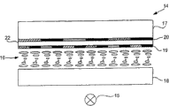
参照图4,根据本发明第一实施例的多视图显示器包括显示板14和背光源15。Referring to FIG. 4 , the multi-view display according to the first embodiment of the present invention includes a
在本实例中,显示板14包括夹在两个透光衬底17、18之间的电光活性材料层(active material)16,该材料例如为液晶材料。这些衬底17、18可以由玻璃或者其它适当的透光材料构成,例如塑料或石英。如果使用了液晶材料,则层16的操作可以基于扭转向列(TN)、超扭转向列(STN)、垂直对准向列(VAN)、光学补偿双折射(OCB)、平面内切换向列(IPS)或者用于调制入射光偏振方向的铁电效应中的任意一种。In the present example, the
该显示板14按照本身公知的方式分成子像素阵列,并且被提供有用于驱动该阵列的有源矩阵或无源矩阵布置(未示出),以允许显示图像。The
提供了滤光层19,其包括沿垂直方向在该显示器上延伸的红、绿和蓝色滤光片的多个列。这些滤光片确定了观看者观看时子像素的颜色。滤光层19中的每个滤光片通过黑矩阵与其相邻的滤光片分隔开。在图4中以及随后的附图中,分别利用线、阴影和剖面线表示了红、绿和蓝色滤光片,而利用全部阴影表示了黑矩阵。A
在滤光层19前,提供了挡板20。该挡板20位于衬底17上,并且通过玻璃或者其它适当的透光材料的片21与滤光层19相分离。In front of the
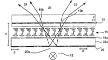
图5中以平面图表示的挡板20包括由黑矩阵22分开的红、蓝和绿色滤光片的多个列。这些滤色片按照与滤光层19中所使用的相反的顺序进行排列。在图4的布置中,按照红、绿和蓝色滤光片的周期顺序配置滤光层19,而挡板20包括蓝、绿和红色滤光片列的顺序。需要在挡板20中使用相反的顺序,以便确保不同颜色的光以相同的角度从显示板出现(发射出来)。如果滤光层19和挡板20使用相同的滤色片顺序,则来自红、绿和蓝色子像素的光将遵循不同的方向,并且将产生其各自的观察区域。The
在该特定实施例中,为了避免生成串扰,挡板20的每列的宽度w等于2p,即子像素间距的两倍。如果需要,如关于本发明其它实施例所述的,这些列可以配置为具有更小的宽度w,或者略微较大的宽度w。In this particular embodiment, in order to avoid generating crosstalk, the width w of each column of
在该特定实施例中,配置滤光层19和挡板20,使得每列中的滤光片与其覆盖的子像素的颜色不相符。然而,滤光层19和挡板20不必按照这种方式配置。在根据本发明的其它布置中,滤光层18和挡板20的多个重叠部分的颜色可以相符。In this particular embodiment, the filter layers 19 and baffles 20 are configured such that the filters in each column do not match the color of the sub-pixels they cover. However, the
可以利用光刻术制造该挡板20,从而形成感光聚合物材料的多个列,其中散布了相关颜色的颜料。红、绿和蓝色列可以由与滤光层19中相应的滤光片颜色相同的颜色的滤(光材)料(filter material)构成,但不必是这样的。The
为了避免串扰,应当配置用于滤光层19和挡板20中的红、绿和蓝色滤光片,使得各个颜色的滤光片的透光光谱不重叠。在这种情况下,从电光活性材料层16发出的光仅能够通过滤光层19和挡板20中颜色相符的区域。换句话说,光不能通过挡板20中给定颜色的列,除非其已经预先通过了滤光层19中相同颜色的滤光片。这限制了如图6所示的显示器发出的光的方向,其中通过滤光层18中的绿色滤光片19b、19e的光通过挡板20的绿色列20b。然而,该绿色列20b将遮挡从红和蓝色滤光片19a、19c、19d、19f发出的光。In order to avoid crosstalk, the red, green and blue filters used in the
利用发射具有明确波长的光的背光源15,能够促进光选择性透过挡板20,并且因此有助于避免串扰。实现这一点的一种方式是利用包括多个发光二极管(LED)的背光源。当红、绿和蓝色LED的光谱准确分离时,透射由特定颜色的LED生成的光而不透射其它光的一个或多个滤色片的结构比较简单。Utilizing a
仍然参照图6,从绿色滤光片19b发出的光通过列20b,并且生成右观察区域23。同时,来自另一绿色滤光片19e的光通过同一列20b,并且生成左观察区域24,利用虚线表示了该左观察区域。当挡板20限制了子像素19b、19e发出的光传播的方向时,位于观察区域22、23之间的中间区域25无串扰。Still referring to FIG. 6 , light emitted from
提供黑矩阵22使得中间区域25的尺寸增大,并且进一步减小或防止了串扰。Providing the
图7表示了不具有黑矩阵的挡板26,其包括红、绿和蓝色滤光材料的多个列。注意,实际上可能存在将滤色片分开的黑矩阵,其对于挡板26的性能的影响可以忽略。图8表示了由包括挡板26和滤光层27的显示器生成的观察区域23’、24’和中间区域25’,其中类似挡板26,滤光层27也不包括具有有效宽度的黑矩阵。中间区域25’的尺寸受到挡板26中列26a的尺寸的限制。在该特定实例中,该挡板26配置有列26a,该列的宽度w等于或小于子像素间距p的两倍。对于99μm大小的典型子像素而言,列间距至多为198μm。Figure 7 shows the
图8还表示了附加观察区域28的形成。如前所述,在该图中,所示的通过红色滤光片27b和27c的光继续通过挡板26的红色列26a,从而形成左、右观察区域23’、24’。然而,来自红色子像素的光也可以通过挡板26的其它红色列,从而生成其它观察区域。如虚线所示,表示了一个实例,其中来自红色滤光片27b的光也通过红色列26b,从而形成附加的观察区域28。尽管未示出,但是通过红色滤光片27c的一部分光也将通过红色列26b,从而形成另一个观察区域,而来自红色滤光片27a和27d的光通过红色列26a、26b等等。按照这种方式,可以通过该挡板26的单一列26a、26b形成多个附加的观察区域。FIG. 8 also shows the formation of an
尽管已经讨论了涉及第二实施例的附加观察区域28的形成,但是也可以由图4的显示器形成该侧视图。Although the formation of the
对于第一实施例的显示器而言,能够按照以下公式计算当在衬底17内相对于法线测量时主观察区域23、24开始和结束的角度
其中w表示单一列20a到20c的宽度,b是滤光层19的黑矩阵的宽度,p是子像素19a到19f的间距,d是滤光层19与挡板20之间的间隔,在这种情况下该间隔是薄片22的厚度,以及j表示列的数量。Wherein w represents the width of a
如果衬底17由折射率n为1.5的玻璃制成,则在衬底17与空气之间的界面处的折射之后,实际观察区域22、23开始和结束的角度α、β由以下等式给出:If the

上述等式中的最小和最大函数用于避免由于全内折射而产生的复合角。The min and max functions in the above equations are used to avoid compound angles due to total internal refraction.
角度α、β取决于挡板20和滤光层19的透射率,如下:The angles α, β depend on the transmittance of the
其中包括系数6,因为每个滤色片的透射率约为1/3,并且列20a到20c的宽度w是子像素19a到19f的间距p的两倍。A factor of 6 is included because the transmittance of each color filter is about 1/3 and the width w of the
图9表示了对于d=0.7mm、p=0.1mm和b=0.025mm的实施例而言,角度α、β与滤光层19和挡板20的透射率之间的关系。在本实例中,生成了两对观察区域23和24、28和29,如果透射率小于≈0.18。第一和第三观察区域23、28包含相同的信息。类似的是,在第二和第四观察区域24、29中呈现了相同的信息。观察区域23、24、28、29不重叠,因此防止了串扰。FIG. 9 shows the relationship between the angles α, β and the transmittance of the
观察区域23、24、28、29的尺寸取决于滤光层19与挡板20之间的间隔d,因此间隔d小的显示器将生成较大的观察区域。图10表示了对于列宽w是子像素间距p的两倍并且其余参数未变的布置而言,角度α、β与间隔d之间的关系。如果间隔d为1mm,则如各个符号所示,生成了六个观察区域23、24、28、28’、29、29’,每个符号分别表示了各个观察区域开始和结束的角度,即α和β。如果厚度d在例如0.35到0.7mm范围内,则生成四个观察区域23、24、28、28’、29、29’。如果d小于0.35mm,则显示器仅生成两个观察区域23、24。尽管间隔的该最小范围产生了少量的观察区域,但是这种结构对于仅需要有限数量的观察区域的汽车用途中使用的显示器而言,可能是最为有效的。The size of the
如果子像素间距p减少了给定的倍数,换句话说,如果提高了分辨率,则观察区域23、24的尺寸可能保持不变,前提是间隔d、黑矩阵宽度b和列宽度w缩放了相同的倍数。因此,如果使用更小的子像素,例如间距p为42μm的子像素,则能够保持观察区域23、24的尺寸,前提是薄片22的厚度d相应减小到以下值:If the subpixel pitch p is reduced by a given factor, in other words, if the resolution is increased, the dimensions of the
仍然参照图7和8,在挡板26和滤光层27不包括黑矩阵的布置中,或者如果黑矩阵的大小对于该显示器的性能仅具有可忽略的影响,则观察区域23、24的开度角为:Still referring to FIGS. 7 and 8 , in arrangements where the
因此,为了获得开度角至少为20°的两个观察区域,所需要的间隔d为:Therefore, to obtain two viewing areas with an opening angle of at least 20°, the required separation d is:
对于子像素的间距p为42μm的布置,该间隔d应小于或等于0.538mm。For an arrangement in which the pitch p of the sub-pixels is 42 μm, the interval d should be less than or equal to 0.538 mm.
如上所述,在已知的LCD中,衬底17的厚度为0.7mm或者1.1mm。为了获得希望的观察区域,位于电光活性材料层16与挡板20之间的薄片22必须比较薄。能够获得如下的适当结构。As mentioned above, in known LCDs, the
参照图4,通过在衬底17上沉积滤色材料以及如果需要沉积黑矩阵来生成挡板20。如果滤光材料是感光聚合物,则利用光刻方法可以实现上述过程,从而形成滤色材料的多个列。该衬底17可以是用于LCD中的常规衬底,其厚度为0.7mm或者1.1mm。然后,将诸如玻璃、石英或者透光塑料之类的透明材料薄片22放置到挡板20的顶部。在本实例中,该薄片22的厚度约为150μm。然后在薄片22的顶部形成滤光层19。利用类似的光刻方法可以形成用于挡板20的滤光层19。如果需要,该滤光层19可以包括黑矩阵。Referring to FIG. 4 , the
图11表示了本发明的第三实施例。不同于第一和第二实施例中挡板20位于滤光层18之前,该挡板20位于背光源15与电光活性材料层16之间。通过按照与上述类似的方式在衬底18上沉积滤色材料以及(如果需要)沉积黑矩阵来生成这种挡板20。该衬底18可以是用于LCD的常规衬底。将透明材料的薄片22a放置到挡板20的顶部。然后,在薄片22a上提供用于操纵电光活性材料层16的装置,例如电极阵列和TFT,通常以16a表示。Fig. 11 shows a third embodiment of the present invention. Unlike the first and second embodiments where the
由于存在挡板20,入射到电光活性材料层16上的光仅能够沿着某些预定方向通过子像素。图11表示了光通过一个列20a和两个滤光片18a、18e的过程,其中列20a和滤光片18b、18e具有相符的颜色。因此,生成两个视图23、24,以及没有串扰的中间区域25。Due to the presence of the
在该特定实施例中,对于挡板20的列而言有利的是其为胆甾型滤光片。由于胆甾型滤光片具有光反射性质,因此能够提高显示器的光效率,这是因为能够将每列20a遮挡的光反射到背光源15中加以利用。In this particular embodiment, it is advantageous for the column of
以上结合第一和第二实施例描述了观察区域开始和结束的角度(分别为α和β)与挡板20和滤光层19之间的间隔d、列20a的宽度w、子像素间距p和黑矩阵宽度b之间的关系。The above describes the starting and ending angles of the observation area (α and β respectively) and the interval d between the
以上的各个实施例产生了对称排列的观察区域23、24。然而,在一些应用中,可能希望非对称排列的观察区域23、24。例如,在汽车用途中,优选的是该显示器朝驾驶员旋转。通过配置具有相对适当对准的挡板20的列20a到20c以及颜色相符的滤光层19的滤光片19a到19f的显示器,能够实现这一点。非对称排列可以基于以上实施例中的任意一个。图12表示了用于根据本发明第四实施例的多视图显示器的滤光层19和挡板20,该滤光层和挡板设置为提供这种非对称排列的观察区域23、24。Each of the above embodiments produces a symmetrical arrangement of
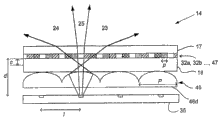
图13表示了根据本发明第五实施例的多视图显示器,其设置为提供两个视图。该显示器包括背光源15、显示板14和透镜状屏幕30。该背光源15设置为输出准直光。然而,在可选实施例中,该背光源可以改为发射亮线。Figure 13 shows a multi-view display according to a fifth embodiment of the invention, arranged to provide two views. The display comprises a
该透镜状屏幕30位于背光源15与显示板14之间,并且使背光源15发出的光聚焦,使得多个亮线照亮该显示板14。透镜状屏幕30的透镜的间距P是子像素的间距p的两倍。在该特定实施例中,子像素的间距p是0.15mm,透镜状屏幕30的透镜间距P是0.3mm。将透镜状屏幕30与电光活性材料层16分开的衬底18的厚度t是0.7mm。The
图14表示了用于显示板14的滤光层31的平面图。还表示了四列位于下面的子像素列32a到32d的位置。配置该滤光层31,使得当该显示器在使用时,将滤光片设置成一连串水平的行。可选的子像素列用于呈现每个视图,使得子像素列32a和32c向第一观察区域23显示信息,同时子像素列32b和32d显示第二观察区域24的信息。FIG. 14 shows a plan view of the
图13表示了通过透镜状屏幕30的一个透镜30a的光线。该透镜30a将亮线成像到子像素上,使得通过一个子像素列32a的光线导向第一观察区域23,并且使通过另一个子像素列32f的光线导向第二观察区域24。利用透镜30b成像的光照射与子像素列32a相邻的子像素列32b,如利用虚线所示的。利用透镜30c成像的光照射与子像素列32b相邻的下一子像素列32c。按照这种方式,利用通过该透镜状屏幕30的不同透镜30a、30b、30c的光照射相邻的子像素列32a、32b、32c、32f。根据将要观看到子像素列32a、32b中显示的信息的观察区域23、24,通过子像素列32a及其相邻子像素列32b的光沿着不同方向传播。FIG. 13 shows light passing through one
图13的多视图显示器还生成多个串扰区域25、33、34。通过显示板14的光的有限光点直径造成了位于观察区域23、24之间的一个串扰区域25。The multi-view display of Figure 13 also generates a number of
在观察区域23、24的外侧边缘处形成串扰区域33、34,该区域是由杂散光造成的。在与观察区域24相邻的串扰区域34中,观看者能够感觉到已经通过子像素32并且显示其它观察区域23的信息的光。由图13中的虚线表示,其表示了来自透镜30a的光通过与子像素32f相邻的子像素32g。该杂散光被导向第二观察区域24。子像素32g显示拟用于第一观察区域23的信息。因此,该杂散光将为串扰区域34中的第一观察区域23产生信息显示。类似的是,在串扰区域33中,可以看到在观察区域23中可见的信息,以及已经穿过子像素32的光显示拟用于观察区域24的信息,如图13中的另一条虚线所示。
观察区域23、24的尺寸取决于背光源15和透镜状屏幕30产生的亮线的开度角,因此具有较小开度角的亮线的布置生成尺寸减小的观察区域23、24。同时,由亮线的宽度确定串扰区域25、33、34的尺寸。衬底17、18的厚度t和子像素的间距p确定了包括观察区域23、24和串扰区域25的最大可利用视角f。在衬底17、18的厚度t为0.7mm并且像素如图13所示那样定向的布置中,最大可利用视角f是72°。如果亮线的宽度是100μm,则串扰区域25的开度角θ’为24°,观察区域23、24各具有24°的开度角。然而,通过选择适当的亮线和透镜状屏幕30的尺寸,可以获得开度角为30°的观察区域23、24。The size of the
尽管与现有技术的显示器相比,图13的显示器生成的观察区域23、24较大,但是还产生了显著的串扰区域25、33、34。在根据第六实施例的多视图显示器中,如图15中所示,通过防止显示器上呈现的信息在区域25、33、34中可见来避免串扰。Although the display of Fig. 13 creates
在图15所示的显示器中,背光源35设置为例如利用多个适当配置的光源和/或利用掩模来发射亮线。该亮线的间距1约为子像素间距p的两倍。透镜状屏幕30位于背光源35与显示板14之间。为了简化该附图,未示出电光活性材料层16。在该图中,子像素32的位置由滤光层31中与其相对应的滤光片的位置来表示。In the display shown in Figure 15, the
由于图15所示的透镜30a、30b与亮线之间对准,因此没有产生由图13的布置中的透镜成像的光的有限光点直径s造成的问题。因此,没有产生中心串扰区域25。Due to the alignment between the
透镜状屏幕30的间距p约等于背光源35产生的亮线的间距1。该透镜位于亮线之间,并且配置有适当的强度,从而将亮线聚焦到子像素上。当亮线成像到子像素上时,该亮线的宽度优选小于像素间距p,以便避免对相邻像素的无意照射,并且因此避免观察区域23、24的边缘处形成串扰区域。The pitch p of the
与图14的显示器一样,利用由透镜状屏幕30的不同透镜成像的沿对应于观察区域23、24的不同方向传播的光照射相邻像素,在该观察区域中各个子像素显示信息。As with the display of Fig. 14, adjacent pixels are illuminated with light imaged by different lenses of the
如果衬底17、18的玻璃厚度为0.7mm,那么多视图显示器生成视角θ为30°的观察区域23、24。该观察区域23、24被中间区域25分开,在该中间区域中没有串扰。图16表示了光线通过图15的显示器的路径,以便显示来自两个各自的子像素的信息。左边的阴影区域对应于用于在观察区域24中显示信息的光线,右边的阴影区域对应于用于观察区域23的相当的光线。If the glass thickness of the
在图15的多视图显示器中,每个亮线聚焦到与实施所述聚焦的透镜状屏幕30的透镜相邻的子像素上。例如,将透镜30a聚焦的亮线成像到子像素32a上,同时将透镜30b聚焦的亮线成像到子像素15b上。对于子像素32a、32b和透镜30a、30b而言,按照这种方式相互对应是没有必要的。可以使用其它配置,其中每个透镜30a、30b将亮线聚焦到不与其相邻的子像素上。在这种配置中,与图15的多视图显示器产生的尺寸相比,其中没有信息可见的中间区域25的尺寸增大。In the multi-view display of Fig. 15, each bright line is focused onto the sub-pixel adjacent to the lens of the
与观看者与多视图显示器之间的距离相比,如果显示板14提供大屏幕面积,则在配置该显示器时必要的是应用“观察点校正”。如果透镜状屏幕30的间距P和亮线的间距1是子像素间距p的两倍,则观看者不能从单一位置看到所显示的整个图像。利用透镜状屏幕30和间距P、1大于子像素间距p的两倍的亮线来进行观察点校正。所需要的对于透镜状屏幕和亮线的间距P、1的调整小于1%,即小于0.02p。例如,约为0.002p的校正就足够了。这种配置允许观看者观察整个显示器。观察点校正的原理还能够用于通过选择亮线和透镜状屏幕30的适当间距1、P来生成具有希望尺寸的观察区域23、24。If the
现在参照图17描述进一步增大观察区域尺寸的另一种技术,该图表示了根据本发明第七实施例的双视图显示器。如图15一样,未示出电光活性材料层16。Another technique for further increasing the viewing area size will now be described with reference to FIG. 17, which shows a dual-view display according to a seventh embodiment of the present invention. As in Fig. 15, the electro-optically
在图15的双视图显示器中,在第一与第二观察区域23、24之间生成中间区域25,其中不能看到信息。利用专用散射片36能够放大该第一和第二观察区域23、24,该散射片置于显示板14前面,如图17所示。这允许在中间区域25中呈现可观看的信息。这个特征可以用来取代优化亮线和透镜状屏幕30的间距1、P,或者作为其补充,以便生成具有希望尺寸的观察区域23、24。In the dual view display of Fig. 15, an
为了避免串扰,该散射片36应当在有限角度范围内散射入射光,该角度范围小于或等于中间区域25的开度角θ’。换句话说,散射轮廓应当较窄。图18a表示了标准的散射轮廓。在标准散射片中,绝大部分光大角度散射,如该轮廓的“肩”37所示。通过对比,该散射片36具有如图17b所示的散射轮廓,其中在相对有限的角度范围内散射光。In order to avoid crosstalk, the
该散射片36可由粗糙表面构成,该表面包括配置为提供有限范围的散射角的许多小平面。图18a表示了具有适当结构的散射表面38的实例。图18b表示了结构化的可选散射表面39的实例。对于该结构化散射表面而言,没有必要包括如图所示的球状元件39a、39b等,然而,无论提供何种结构,其应当具有与子像素的间距p相比很小的尺寸,例如10到50μm。The
在图20所示的本发明的第八实施例中,配置多视图显示器,使其能够在双视图模式与单一视图模式之间切换。当以双视图模式工作时,每个观看者能够看到的子像素达到一半。在单一视图模式下,对于所有观看者而言所有子像素都是可见的,换句话说,为每个观看者呈现相同的信息。In an eighth embodiment of the invention shown in FIG. 20, a multi-view display is configured such that it can be switched between a dual-view mode and a single-view mode. When working in dual-view mode, each viewer sees half of the sub-pixels. In single view mode, all sub-pixels are visible to all viewers, in other words, the same information is presented to each viewer.
在图20的显示器中,漫射片40位于透镜状屏幕30与电光活性材料层16(未示出)之间。利用透光特性随施加到其上的电场变化的材料构成该漫射片40。例如,可以利用聚合物扩散液晶(PDLC)构成该漫射片40,当施加电场时其为透明的,但是在没有电场的情况下其漫射。漫射片40的另一种适当材料是液晶凝胶,其通常为透明的,但是当施加电压时变为漫射的。In the display of Figure 20, the
通过施加电场,该漫射片40能够在至少两种状态之间切换。由电压源41提供电场,并且利用开关42对电场进行控制。在其第一状态下,漫射片40为透明的,因此利用背光源35产生的亮线照射该子像素。该显示器按照上述涉及第六实施例的方式生成多个视图。当漫射片40切换到第二状态时,其漫射背光源36生成的亮线,从而均匀照射子像素。该显示器生成单一视图,使得观看者能够感觉到所有子像素显示的信息,而不管它们位于第一或第二观察区域23、24,还是位于中间区域25。By applying an electric field, the
如上所述,关于现有的布置,串扰和观察区域的尺寸有限的问题部分是由于子像素的间距p相对于挡板与显示板之间的间隔d小而造成的。该间隔d通常受到置于挡板与显示板之间的玻璃或类似材料的薄片厚度t控制。在本发明的第九实施例中克服了这个问题,现在将对其进行描述。As mentioned above, with existing arrangements, the problems of crosstalk and the limited size of the viewing area are partly due to the small pitch p of the sub-pixels relative to the spacing d between the bezel and the display panel. This spacing d is generally controlled by the thickness t of a sheet of glass or similar material placed between the bezel and the display panel. This problem is overcome in a ninth embodiment of the present invention, which will now be described.
在常规的多视图显示器中,呈现信息的显示板的相邻子像素列对准不同的观察区域。例如,如果将图14所示的滤光层31和下面的子像素32用于已知的双视图显示器中,第一列子像素32a将为第一观察区域显示信息,而第二列子像素32b将为第二观察区域显示信息等等。现在将描述与常规不同的多个实施例。In conventional multi-view displays, adjacent columns of sub-pixels of the display panel presenting information are aligned to different viewing areas. For example, if the
图21表示了用于图22所示的根据本发明第九实施例的多视图显示器的子像素阵列的一部分,其设置在列32a到32d中,等等。Fig. 21 shows a part of a sub-pixel array for the multi-view display according to the ninth embodiment of the invention shown in Fig. 22, arranged in
在图21中,标记为“A”或“B”的子像素分别表示子像素向第一观察区域23呈现信息,还是向第二观察区域24呈现信息。中间子像素列32c、32f将“A”子像素列32a、32b和“B”子像素列32d、32e分开,该中间子像素列保持关闭或为“暗”,同时为观察区域23、24显示信息。In FIG. 21 , the sub-pixels marked “A” or “B” indicate whether the sub-pixel presents information to the
在该特定实施例中,相邻的子像素列用于向给定观察区域呈现信息。列32a和32b中的子像素设置为向第一观察区域23呈现信息,而子像素32d和32e用于为第二观察区域23显示信息。In this particular embodiment, adjacent columns of sub-pixels are used to present information to a given viewing area. The subpixels in
在图22的显示器中,包括狭缝44的后挡板43位于背光源15与显示板14之间。该狭缝44与中间暗像素列32c、32f对准,并且具有与子像素间距p相等的宽度w。In the display of FIG. 22 , a
按照这种方式,该子像素阵列用作第二挡板,因为光仅能够通过“A”和“B”子像素列32a、32b、32d、32e。出现中间列32c、32f防止观察区域23、24之间的区域25中的串扰。In this way, the sub-pixel array acts as a second baffle, since light is only able to pass through the "A" and "B"
在该特定实施例中,狭缝44的宽度w匹配子像素32的间距p。然而,在狭缝44的宽度w小于子像素的间距p的可选布置中,也能够防止串扰。观察区域23、24的开度角取决于狭缝43的宽度w,以及挡板42与子像素32之间的间隔d和与每个狭缝44相关的视图数量。然而,如果该挡板包括宽度w大于子像素间距p的狭缝,则所得到的观察区域23、24将重叠,从而产生串扰。In this particular embodiment, the width w of the
在图22中利用虚线表示了观察区域23’的结构,其中由子像素列32g和32h显示的信息是可见的。在观察区域23’内,存在仅可以看到来自子像素列32g、32h之一的信息的区域。这些区域分别标记为23’a和23’b。在这些区域之间是重叠区域23’c,其中能够同时观察到由这两个子像素列32g、32h显示的信息。In Fig. 22, the structure of the viewing area 23' is shown with dotted lines, in which the information displayed by the
对于该特定实例而言,如果将两个相邻子像素列32a和32b、32d和32e用于为每个观察区域23、24呈现信息,并且狭缝44的宽度w等于子像素的间距p,能够按照以下方式计算重叠区域23’c的范围。分别用α和β表示重叠区域23’c开始和结束的角度。然而,在衬底18与空气之间的界面处发生折射之前,开始和结束的角度为:For this particular example, if two adjacent columns of
图23是表示作为pld的函数的角度α和β。对于子像素间距p为0.099mm并且间隔d为0.7mm的显示器而言,α等于12°,并且β等于24°。因此,重叠区域23’c的开度角θ为12°。Figure 23 is a graph showing the angles α and β as a function of pld. For a display with a subpixel pitch p of 0.099 mm and a spacing d of 0.7 mm, α equals 12° and β equals 24°. Therefore, the opening angle θ of the overlapping region 23'c is 12°.
可以采用多个可选措施来增大该重叠区域23’c的开度角。例如,在本发明的第十实施例中,能够将漫射片45置于显示板14前,如图24所示。如果该漫射片45具有例如10°的角展度,则重叠区域23’c的尺寸增大是以产生有限串扰区域、垂直方向分辨率的一定损失和显示板14的日光对比度减少为代价的。然而,如果提供仅在水平方向上散射的漫射片45,则可以降低垂直分辨率的损失或者完全避免这种损失。此外,能够使用仅在特定方向上散射光的漫射片45,例如Madico制造的
通过例如减小衬底18的厚度,从而减小挡板43与子像素32之间的间隔d,也能够增大观察区域23、24与重叠区域23’c的尺寸。By, for example, reducing the thickness of the
通过在更接近电光活性材料层(未示出)的位置有效地生成亮线,也能够获得类似的结果。将这个概念应用于图25所示的根据本发明第十一实施例的多视图显示器中。Similar results can also be obtained by efficiently generating bright lines closer to the electro-optically active material layer (not shown). This concept is applied to the multi-view display according to the eleventh embodiment of the present invention shown in FIG. 25 .
在该实施例中,透镜状屏幕46位于背光源35与子像素32之间,该背光源设置为生成亮线。该透镜状屏幕46将亮线成像到距子像素的距离为c的位置。透镜状屏幕46的间距P等于背光源35生成的亮线的间距1。定位该透镜状屏幕46,使其透镜与亮线对准。在该实例中,如图21所示操纵该子像素32,使得“A”子像素列32a、32b、“B”子像素列32d、32e和暗子像素列32c、32e的排列具有6个子像素的周期。出于这个原因,透镜状屏幕46的间距是子像素间距p的六倍。In this embodiment, a
在该特定实施例中,暗子像素列32c、32f与背光源35生成的亮线对准,但是该暗子像素列32c、32f与亮线没有必要按照这种方式对准。如果多视图显示器设置为消除中间区域25中的串扰,则该亮线的宽度应当小于或者等于子像素的间距p。In this particular embodiment, the
因为透镜的间距P是子像素间距p的六倍,所以c的最大值是衬底18的厚度的5/11。这实际上强p/d的比率减小了5/11倍。对于子像素间距p为0.099mm的情况而言,有效的p/d是0.064。这种布置将提供α为26°、β为52°的重叠区域23’c,换句话说,开度角θ为26°。这优于图22的多视图显示器获得的12°的开度角。Since the pitch P of the lenses is six times the pitch p of the sub-pixels, the maximum value of c is 5/11 of the thickness of the
理想情况下,背光源35产生的亮线的开度角使得来自给定亮线的光通过与其对准的透镜。例如,为了满足这个要求,来自在35b处生成的亮线的光仅通过透镜46b,而不通过相邻的透镜46a、46c。因此,为了提供薄的多视图显示器,亮线的开度角应当小。实际上,该开度角可以大于单透镜46a的间距。这就造成来自35a处的亮线的光通过相邻的透镜46b,并且产生其它的、不需要的亮线。Ideally, the opening angle of the bright lines produced by the
通过配置背光源35与透镜状屏幕46之间的距离e,使得透镜46a到46d提供了等于正整数的放大系数,能够防止具有大开度角的亮线造成的问题。图26表示了这种成像方式的一个实例,该图表示了图25的多视图显示器,其中背光源35与透镜状屏幕46之间的距离e使得透镜46a到46d的放大系数等于1。这使得来自35d处的亮线的光进入相邻透镜46c,从而在与来自35b处的亮线的光相同的位置成像。换句话说,杂散光在距子像素32的距离为c、与透镜46b、来自32b的亮线以及在该特定实施例中的覆盖暗像素列32g对准的位置成像。By configuring the distance e between the
当根据图21中的方式操纵该子像素阵列时,仅将三分之一的子像素用于呈现给定的视图,如上所述,这能导致观看者正在观看的显示图像的子像素化。此外,这种布置与常规的滤光片布局不相兼容,在常规滤光片布置中,该滤光片设置为一连串的红、绿和蓝色列。这是因为在重叠区域23’c内,仅能够观看到三个可利用原色中的两个。When the sub-pixel array is manipulated in the manner shown in Figure 21, only one-third of the sub-pixels are used to render a given view, which, as described above, can lead to sub-pixelation of the displayed image being viewed by the viewer. Furthermore, this arrangement is not compatible with conventional filter arrangements in which the filters are arranged in a succession of red, green and blue columns. This is because only two of the three available primary colors can be viewed within the overlapping region 23'c.
利用滤色层47的特殊布局,能够克服这个问题。例如,滤光层47中的滤光片可以配置为多个水平行,而不是垂直列或者二维滤色片阵列。在任意一种布置中,来自单一列32a中的不同子像素的光可以通过不同的滤色片,使得重叠区域23’c中可见的信息包括所有可以利用的原色。另一种选择是使用具有不同数量的原色的滤光层47。例如,如果该滤光层47设置为一连串红、绿、蓝和黄色滤光片列,则滤光层与子像素排列之间不存在不兼容性。With a special layout of the
在包括例如图22所示的挡板的实施例中,另一种可能的解决方案是将滤光层47定位在与挡板43成一定角度的位置,尽管这可能导致一些串扰的生成。例如,通过将滤光层47和/或挡板43设置为与子像素阵列成一定角度,该滤光层47和挡板43可以设置成使得它们之间的夹角的正切值为1/3,即约为18.4°。In embodiments comprising baffles such as shown in Fig. 22, another possible solution is to position the
以上的讨论假设从狭缝44发出的亮线的开度角小于或等于6p,即在图21所示的子像素排列的一个周期之内。实际上,光的角展度可以更大,尽管这将造成观察区域23、24的重叠。例如,图22表示了两个光线,如虚线所示,该光线通过子像素32i、32j。这就产生了另一个观察区域(未示出),在该区域内观察区域23中所示的信息重叠。The above discussion assumes that the opening angle of the bright lines emitted from the
图27表示了用于根据本发明第十二实施例的多视图显示器中的子像素的可选排列。换句话说,列32a用于向第一观察区域23呈现信息,而列32c用于显示第二观察区域24中观察的信息。位于“A”子像素(例如列32a)与“B”子像素(例如列32c)之间的列32b、32d在该多视图显示器使用时保持关闭。尽管这种排列具有与子像素的间距p相等的有效间距,但是暗子像素32b、32d的存在抑制了串扰。Fig. 27 shows an alternative arrangement of sub-pixels for use in a multi-view display according to a twelfth embodiment of the present invention. In other words,
图28表示了包括根据图27工作的子像素阵列的多视图显示器。在该特定实例中,狭缝43的宽度w等于子像素的间距p。该多视图显示器生成两个观察区域23、24,以及不存在串扰的中间区域25。Figure 28 shows a multi-view display comprising an array of sub-pixels operating according to Figure 27. In this particular example, the width w of the
尽管图28的多视图显示器减少或防止了串扰,但是由于每四个子像素中仅有一个用于提供给定的视图,因而显示板14的分辨率下降。此外,由于子像素阵列的交替列32b、32d关闭,因此多视图显示器的光效率下降。Although the multi-view display of Figure 28 reduces or prevents crosstalk, the resolution of the
图29表示了用于根据本发明第十三实施例的多视图显示器中的子像素阵列。在这种排列中,将三个相邻的子像素列32a、32b、32c用于向第一观察区域呈现信息,并且将三个列32e、32f、32g用于向第二观察区域显示信息。提供中间列32d、32h,当该多视图显示器使用时该中间列保持关闭。在该实施例中,将每八个子像素中的三个子像素用于向给定观察区域显示信息。因此,本实施例与第九到第十二实施例相比具有更高的光效率,此外,本实施例允许使用常规的红、绿和蓝色滤色片的布局。然而,在本实施例中,以及在使用不只三个相邻像素列提供给定视图的其它实施例中,在各列之间存在较大的间隔i,以用于提供特定的视图。在本特定实例中,该间隔i在列32c和32i之间延伸。间隔i增大会造成可见的赝像。Fig. 29 shows a sub-pixel array used in a multi-view display according to a thirteenth embodiment of the present invention. In this arrangement, three adjacent columns of sub-pixels 32a, 32b, 32c are used to present information to the first viewing area and three
在上述第九到第十三实施例中,子像素有效地用作挡板,从而允许光通过选定的子像素,以便防止串扰和/或提供尺寸增大的观察区域23、24。由于图21、27和29的排列在如何采用单个的子像素列32a到32h,即关闭还是打开给定子像素列32a到32h,以及如果打开将要显示哪些信息的方面不同。因此,通过相应操纵子像素阵列,能够将单个的多视图显示器设置为在根据这些排列中的两个或多个排列的操作模式之间切换,或者在一个或多个多视图模式与单一视图模式之间切换,其中可以对后挡板43进行相应的修改。In the ninth to thirteenth embodiments described above, the sub-pixels effectively act as baffles, allowing light to pass through selected sub-pixels in order to prevent crosstalk and/or provide
在这方面,可以用可切换的挡板取代后挡板43,该挡板例如液晶盒或者其它光闸类型的器件,从而提供能够在多视图与单一视图模式之间切换的显示器。一种显示器包括液晶盒47形式的挡板。能够将液晶盒48切换到第一状态,该状态下其按照与挡板43类似的方式工作。该液晶盒48的像素或子像素用于形成透光部分,该部分利用垂直线表示,还用于形成暗部分,其对应于第九实施例中的狭缝44和挡板43的不透明部分。在这种状态下,该显示器生成如上所述的多个观察区域23、24。当切换到第二状态时,该液晶盒48变为基本透明或者完全透明的。因此,该显示器可以用于呈现单一视图,其中可以照射显示板14的所有子像素32。In this regard, the
如果需要,该液晶盒48和滤光层47可以彼此成角度排列,如以上结合具有六列周期的子像素排列所述的。If desired, the
该显示器可以配置成当液晶盒48处于其第一状态时能够通过相应操纵液晶盒48来改变所生成的透光部分和暗部分的排列。例如,图30的显示器使用了图21所示的子像素32的排列,其具有六个子像素的周期。可以重新配置该显示器,从而通过如图29所示操纵子像素32并且通过操纵液晶盒48以提供具有适当周期的挡板,来使用具有八个子像素周期的排列。在这种情况下,操纵该液晶盒48使得每四个子像素列32是透光的。The display may be configured such that the resulting alignment of the transparent and dark portions can be altered by corresponding manipulation of the
上述第九、第十、第十二和第十三实施例分别包括位于背光源15和子像素32之间的挡板43、48。然而,这些排列中的挡板43、48可以改为置于子像素32前。图31表示了根据本发明第十四实施例的具有前挡板的显示器的实例。该显示器类似第十三实施例的显示器,其中该挡板是能够在第一状态与第二状态之间切换的液晶盒48,在第一状态下,仅有部分液晶盒48是透光的,用于呈现多个视图,而在第二状态下,该液晶盒主要或者完全是透光的,其中该显示器用于生成单一视图。如先前实施例一样,如果需要,该挡板48和滤光层47可以配置成使得挡板与滤光层47中滤光片的透光部分相对彼此倾斜,从而来自通过给定子像素列32a到32g的亮线的光继而通过滤光层的两个或多个相邻的滤光片,从而根据不只一个原色产生视图。The ninth, tenth, twelfth and thirteenth embodiments described above include
如以上结合第十一实施例所述的,通过提供漫射片和/或透镜状屏幕,可以进一步增大第十和第十一实施例的观察区域23、24或者重叠区域23’c的开度角。As described above in connection with the eleventh embodiment, the opening of the
在第九到第十四实施例中,分别根据具有六个、四个和八个子像素周期的排列操纵该子像素阵列,能够将选定子像素列保持暗的排列的原理用于提供具有其它周期的排列。此外,相同数量的子像素列用于每个视图是没有必要的,并且图21、27和29的子像素布局可以分开,以便提供非对称的显示器。例如,可以使用一个周期包括三个“A”子像素列、两个“B”子像素列和两个中间列的排列。In the ninth to fourteenth embodiments, the subpixel array is manipulated according to arrangements with six, four and eight subpixel periods respectively, the principle of being able to keep selected subpixel columns dark is used to provide other Periodic arrangement. Furthermore, it is not necessary that the same number of subpixel columns be used for each view, and the subpixel layouts of Figures 21, 27 and 29 can be split to provide an asymmetric display. For example, an arrangement including three "A" sub-pixel columns, two "B" sub-pixel columns, and two middle columns may be used for one period.
图32表示了根据本发明的显示系统。该显示系统包括根据第一到第三、第五和后来的实施例中的任意一个的多视图显示器49,该显示器被设置为生成两个观察区域23、24,在这两个区域中显示了用于观看者50、51的信息。该显示器49包括或者连接到控制器52,该控制器设置为操纵该显示板14。例如,如果显示板14包括受到TFT阵列控制的液晶材料层16,则控制器52将根据将要显示的图像数据操纵TFT。如果显示器49包括可切换漫射片36,则控制器52也可以控制电压源41和切换装置42。如果该显示器49包括可切换挡板,例如结合第十四和十五实施例描述的液晶盒47,则控制器52还可以例如利用专用TFT阵列控制该液晶盒47,以提供具有希望配置的挡板。Fig. 32 shows a display system according to the present invention. The display system comprises a
该图像数据由一个或多个数据源54生成或接收。例如,该显示系统可以安装在汽车53中,如图5所示,并且一个数据源54可以是设置为在与驾驶员50相关的观察区域23中生成并呈现路线信息的处理器。可选择的是,或者此外,可以从诸如数字通用盘(DVD)播放器、视频紧凑盘(VCD)播放器或者接收器的数据源54获得图像数据,该接收器设置为通过陆地或卫星网络接收视频或音频-视频信号,例如电视接收器或者视频电话接收器。适当数据源54的另一个实例是设置为连接到计算机网络(例如互联网)的终端。The image data is generated or received by one or more data sources 54 . For example, the display system may be installed in a
如果需要,可以提供音频输出装置,以呈现与所显示的信息相关的音频信号。可以由外部源和/或控制器52提供音频信号。例如,可以提供扩音器55或者配置为通过一组或多组头戴耳机提供声音的输出(未示出)。Audio output means may be provided, if desired, to present audio signals associated with the displayed information. The audio signal may be provided by an external source and/or
图33表示了包括根据本发明的多视图显示器56的另一种显示系统。在该图中,未示出处理器52、数据源54和音频输出装置55。在本实例中,显示器56设置为生成观察区域23、24的非对称排列,使得观察区域23朝向一个观看者50。例如,在汽车用途中,可以对准该观察区域23,使得驾驶员50可以在视线不离开道路的情况下观看所述信息。已经结合第四实施例讨论了非对称排列的观察区域23、24的产生。然而,也能够修改多个其它实施例以生成这种排列。例如,可以修改第一、第二、第九、第十和第十二到第十五实施例,以通过按照适当方式对准挡板20、26、43、47和滤光层19、27、41而生成非对称分布的观察区域23、24。Figure 33 shows another display system comprising a
通过阅读本说明书,其它的变化和修改对于本领域技术人员而言是显而易见的。这种变化和修改可以涉及在包括液晶显示板或其它显示板及其组件的显示设备的设计、制造和使用中已经公知的相同和其它特征,并且可以用来取代或添加到本文中已经描述的特征的相同和其它特征。From reading the present specification, other changes and modifications will be apparent to those skilled in the art. Such changes and modifications may involve the same and other features already known in the design, manufacture and use of display devices, including liquid crystal display panels or other display panels and components thereof, and may be used in place of or in addition to those already described herein. The same and other characteristics of the characteristics.
尤其是,以上实施例是适用于汽车用途的双视图显示器。本发明可以用于同时提供不只两个不同的视图。例如,可以提供按照与本发明的第九到第十三实施例相似的方式提供“A”、“B”、“C”和“D”的子像素布局。此外,本发明不限于用于汽车环境中的多视图显示器,并且能够用于在观看者可能仍在给定观察区域内的其它用途中向多个观看者呈现不同信息。这些其它用途包括飞机座舱、大客车、等候室、阶梯教室中的显示器等等。In particular, the above embodiments are dual view displays suitable for automotive use. The invention can be used to provide more than two different views at the same time. For example, sub-pixel layouts providing "A", "B", "C", and "D" in a similar manner to the ninth to thirteenth embodiments of the present invention may be provided. Furthermore, the invention is not limited to multi-view displays for use in an automotive environment, and can be used to present different information to multiple viewers in other uses where the viewers may still be within a given viewing area. These other uses include displays in aircraft cockpits, buses, waiting rooms, lecture theaters, and the like.
已经结合显示板14的子像素并且特别是其间距p描述了以上实施例的特征。然而,可以配置根据以上实施例中的任意一个实施例的多视图显示器,使得任意亮线透镜状屏幕的间距或者其它参数根据像素的间距p改变。如果显示板14是单色显示器,则这是特别适当的。The features of the above embodiments have been described in connection with the sub-pixels of the
如上所述,显示板14为液晶设备不是必须的。也可以使用其它显示板,其不必是光闸类型。适当的可选显示板包括电泳显示器、电铬显示器、电润湿显示器和微机械显示器,例如微机电系统(MEMS)显示器。在包括前挡板的排列中,例如本发明的第一、第二、第四和第十五实施例,该显示板14可以是透光显示设备,例如阴极射线管(CRT)、发光二极管阵列、有机发光二极管(OLED)显示器、场发光显示器(FED)等。As mentioned above, it is not necessary for the
如果合适,可以将结合各个实施例所述的特征组合起来。例如,尽管已经关于各个实施例描述了通过选择亮线的适当间距I和透镜状屏幕来使用专用的散射片和可切换漫射片以及观察区域的配置,但是可以结合使用这些特征,从而提供其各自的优点。Features described in connection with the individual embodiments may be combined if appropriate. For example, while the use of dedicated diffusers and switchable diffusers and configurations of viewing areas by selection of an appropriate spacing I of bright lines and a lenticular screen have been described with respect to various embodiments, these features may be used in combination to provide other respective advantages.
在包括挡板的实施例中,挡板狭缝的宽度w不必等于给定正整数与像素或者子像素的间距p的乘积。如上所述,宽度w可以小于该值,以便增大观察区域的间隔,或者该宽度w可以更大,以便实现观看点校正或者获得希望尺寸的观察区域,如以上结合本发明的选定实施例所讨论的。In embodiments including baffles, the width w of the baffle slit need not be equal to the product of a given positive integer and the pixel or sub-pixel pitch p. As mentioned above, the width w can be smaller than this value in order to increase the separation of the viewing areas, or the width w can be larger in order to achieve point of view correction or obtain a viewing area of a desired size, as above in connection with selected embodiments of the present invention discussed.
此外,已经仅结合本发明的第七和第八实施例描述了提供专用的散射片和可切换漫射片,以便允许多视图显示器在多视图与单一视图模式之间切换。然而,如果合适,这种漫射片可以包含在本发明其它实施例中的任意一个中。此外,可以操纵该可切换漫射片,从而利用用于多个视图的亮线照射显示板的一个区域,同时在显示板的另一个区域上同时提供均匀照射,以提供单一视图。Furthermore, the provision of dedicated diffusers and switchable diffusers in order to allow the multiview display to switch between multiview and single view modes has only been described in connection with the seventh and eighth embodiments of the present invention. However, such a diffuser may be included in any of the other embodiments of the invention, if appropriate. Furthermore, the switchable diffuser can be manipulated to illuminate one area of the display panel with bright lines for multiple views while simultaneously providing uniform illumination over another area of the display panel to provide a single view.
已经仅结合第四实施例描述了使用多视图显示器生成非对称观察区域排列。然而,可以将上述的其它实施例设置为生成这种非对称排列。例如,在第二和第三实施例中可以进行修改,使得颜色挡板和滤光层可以对准以按照与图12所示类似的方式产生非对称观察区域。类似的是,在基于本发明第九、第十和第十二到第十五实施例的排列中,也按照这种方式对准挡板和滤光层。Generating an asymmetric viewing area arrangement using a multi-view display has only been described in connection with the fourth embodiment. However, other embodiments described above may be arranged to generate such an asymmetric arrangement. For example, modifications can be made in the second and third embodiments so that the color baffle and filter layer can be aligned to create an asymmetrical viewing area in a manner similar to that shown in FIG. 12 . Similarly, in the arrangements based on the ninth, tenth and twelfth to fifteenth embodiments of the present invention, the baffles and filter layers are also aligned in this manner.
尽管在本申请中已经将权利要求明确表述为特征的特定组合,但是应当理解本发明公开的范围还包括本发明中明确或隐含公开的新颖特征或特征的新颖组合或者其任何概括,无论其是否涉及如任何权利要求目前所要求保护的相同发明以及无论其是否减轻了本发明所涉及的任意一个或者所有相同的技术问题。因此,本申请人预先告知在实施本申请或者由本申请获得的任何其它申请过程中,可以将新的权利要求明确表述为这些特征和/或这些特征的组合。Although claims have been expressly stated in this application as specific combinations of features, it should be understood that the scope of the disclosure of the present invention also includes novel features or novel combinations of features disclosed in the present invention, explicitly or implicitly, or any generalization thereof, regardless of their whether it involves the same invention as any claim presently claims and whether it mitigates any or all of the same technical problems to which the present invention is concerned. Accordingly, the applicants forewarn that during the prosecution of this application or any other application resulting from this application, new claims may be expressly formulated to these features and/or combinations of these features.
Claims (17)
Applications Claiming Priority (2)
| Application Number | Priority Date | Filing Date | Title |
|---|---|---|---|
| GB0322681.8 | 2003-09-27 | ||
| GBGB0322681.8A GB0322681D0 (en) | 2003-09-27 | 2003-09-27 | Multi-view display |
Publications (2)
| Publication Number | Publication Date |
|---|---|
| CN1856813A CN1856813A (en) | 2006-11-01 |
| CN100555373C true CN100555373C (en) | 2009-10-28 |
Family
ID=29286970
Family Applications (1)
| Application Number | Title | Priority Date | Filing Date |
|---|---|---|---|
| CNB2004800279423A Expired - Lifetime CN100555373C (en) | 2003-09-27 | 2004-09-23 | Multi-view display |
Country Status (11)
| Country | Link |
|---|---|
| US (3) | US8045069B2 (en) |
| EP (3) | EP1680702B1 (en) |
| JP (3) | JP5026790B2 (en) |
| KR (1) | KR101123196B1 (en) |
| CN (1) | CN100555373C (en) |
| AT (1) | ATE472120T1 (en) |
| DE (1) | DE602004027826D1 (en) |
| ES (2) | ES2389056T3 (en) |
| GB (1) | GB0322681D0 (en) |
| TW (1) | TWI380064B (en) |
| WO (1) | WO2005031444A2 (en) |
Cited By (1)
| Publication number | Priority date | Publication date | Assignee | Title |
|---|---|---|---|---|
| CN108353160A (en) * | 2015-11-10 | 2018-07-31 | 皇家飞利浦有限公司 | Display device and display control method |
Families Citing this family (111)
| Publication number | Priority date | Publication date | Assignee | Title |
|---|---|---|---|---|
| TWI289708B (en) * | 2002-12-25 | 2007-11-11 | Qualcomm Mems Technologies Inc | Optical interference type color display |
| CN1846030A (en) * | 2003-09-04 | 2006-10-11 | 皇家飞利浦电子股份有限公司 | Road-marking system |
| GB0322681D0 (en) | 2003-09-27 | 2003-10-29 | Koninkl Philips Electronics Nv | Multi-view display |
| JP4504008B2 (en) * | 2003-12-22 | 2010-07-14 | オリンパス株式会社 | Video display device |
| US7342705B2 (en) | 2004-02-03 | 2008-03-11 | Idc, Llc | Spatial light modulator with integrated optical compensation structure |
| US7630123B2 (en) * | 2004-09-27 | 2009-12-08 | Qualcomm Mems Technologies, Inc. | Method and device for compensating for color shift as a function of angle of view |
| US20060066586A1 (en) * | 2004-09-27 | 2006-03-30 | Gally Brian J | Touchscreens for displays |
| US8013944B2 (en) | 2004-10-25 | 2011-09-06 | Koninklijke Philips Electronics N.V. | Display device for reducing cross-talk between displayed images |
| KR20060053454A (en) * | 2004-11-16 | 2006-05-22 | 삼성에스디아이 주식회사 | Filter for display device, and display device having same |
| JP2007041489A (en) * | 2004-12-14 | 2007-02-15 | Fujitsu Ten Ltd | Display device, frame member, and reflection suppressing member |
| KR101195929B1 (en) * | 2005-05-20 | 2012-10-30 | 삼성전자주식회사 | Multi-channel imaging system |
| WO2007007483A1 (en) | 2005-07-11 | 2007-01-18 | Sharp Kabushiki Kaisha | Display device |
| KR101170797B1 (en) * | 2005-07-26 | 2012-08-02 | 삼성전자주식회사 | 3D image display using integral imaging technology |
| JP5020961B2 (en) * | 2005-10-27 | 2012-09-05 | コーニンクレッカ フィリップス エレクトロニクス エヌ ヴィ | Directional light output device such as multi-view display |
| JP2007160974A (en) * | 2005-12-09 | 2007-06-28 | Olympus Corp | On-vehicle information reproduction device |
| EP1967015A2 (en) | 2005-12-21 | 2008-09-10 | Koninklijke Philips Electronics N.V. | Backlight arrangement |
| JP5552204B2 (en) * | 2006-03-27 | 2014-07-16 | 株式会社ジャパンディスプレイ | Display device |
| KR100922754B1 (en) * | 2006-09-12 | 2009-10-21 | 삼성모바일디스플레이주식회사 | Dual screen display panel |
| EP1905634A1 (en) | 2006-09-26 | 2008-04-02 | C.R.F. Societa' Consortile per Azioni | Display panel for a motor-vehicle dashboard |
| WO2008045207A2 (en) * | 2006-10-06 | 2008-04-17 | Qualcomm Mems Technologies, Inc. | Light guide |
| CN101600901A (en) * | 2006-10-06 | 2009-12-09 | 高通Mems科技公司 | Optical loss structure integrated in illumination device of display |
| EP1946162A2 (en) * | 2006-10-10 | 2008-07-23 | Qualcomm Mems Technologies, Inc | Display device with diffractive optics |
| JP4255032B2 (en) * | 2007-03-15 | 2009-04-15 | 富士通テン株式会社 | Display device and display method |
| WO2008110991A1 (en) * | 2007-03-15 | 2008-09-18 | Koninklijke Philips Electronics N.V. | A multiple view display and a computer system |
| KR101350475B1 (en) * | 2007-04-12 | 2014-01-15 | 삼성전자주식회사 | Highly efficient 2D/3D switchable display device |
| JP2009069567A (en) * | 2007-09-14 | 2009-04-02 | Seiko Epson Corp | Electro-optical device and electronic apparatus |
| US8068710B2 (en) | 2007-12-07 | 2011-11-29 | Qualcomm Mems Technologies, Inc. | Decoupled holographic film and diffuser |
| CN101477265B (en) * | 2008-01-03 | 2012-02-01 | 奇美电子股份有限公司 | Liquid crystal display device, multi-view liquid crystal display panel and manufacturing method thereof |
| US20090273721A1 (en) * | 2008-01-23 | 2009-11-05 | Michael Dhuey | Multi-View Display Using Light Pipes |
| WO2009102733A2 (en) * | 2008-02-12 | 2009-08-20 | Qualcomm Mems Technologies, Inc. | Integrated front light diffuser for reflective displays |
| KR100918065B1 (en) * | 2008-03-31 | 2009-09-18 | 삼성모바일디스플레이주식회사 | Display device and driving method thereof |
| EP2279530B1 (en) * | 2008-04-11 | 2013-06-26 | QUALCOMM MEMS Technologies, Inc. | Method for improving pv aesthetics and efficiency |
| CN101576680B (en) * | 2008-05-08 | 2013-06-12 | 群创光电股份有限公司 | Liquid crystal display device and assembly method thereof |
| US20090323144A1 (en) * | 2008-06-30 | 2009-12-31 | Qualcomm Mems Technologies, Inc. | Illumination device with holographic light guide |
| US20100002006A1 (en) * | 2008-07-02 | 2010-01-07 | Cisco Technology, Inc. | Modal Multiview Display Layout |
| KR101290013B1 (en) * | 2008-10-07 | 2013-07-30 | 엘지디스플레이 주식회사 | Multi-view Display Device |
| TWI382207B (en) * | 2008-12-08 | 2013-01-11 | Chimei Innolux Corp | Color filter substrate, multi-view liquid crystal display and manufacturing method of color filter substrate |
| TWI423247B (en) * | 2008-12-26 | 2014-01-11 | Wistron Corp | Projecting system capable of switching programs corresponding to a plurality of frames projected from a multiple view display and method thereof |
| US20100293502A1 (en) * | 2009-05-15 | 2010-11-18 | Lg Electronics Inc. | Mobile terminal equipped with multi-view display and method of controlling the mobile terminal |
| DE202009016729U1 (en) * | 2009-12-09 | 2011-04-28 | Heise, Sebastian, Dipl.-Ing. (FH) | Lighting device with at least one LED |
| KR20110109565A (en) * | 2010-03-31 | 2011-10-06 | 삼성전자주식회사 | Backlight unit, 3D display and 3D image forming method having the same |
| DE102010024700A1 (en) * | 2010-06-23 | 2011-12-29 | Trw Automotive Electronics & Components Gmbh | Icon display element for a vehicle interior |
| EP2589227A2 (en) * | 2010-06-30 | 2013-05-08 | TP Vision Holding B.V. | Multi-view display system and method therefor |
| DE102010031192B4 (en) * | 2010-07-09 | 2022-01-20 | Preh Gmbh | Lenticular lighting device and control element |
| KR20120010023A (en) * | 2010-07-23 | 2012-02-02 | 엘지디스플레이 주식회사 | Stereoscopic Display and Manufacturing Method Thereof |
| KR101669619B1 (en) * | 2010-07-26 | 2016-10-26 | 삼성전자주식회사 | Rendering system and method based on weighted value of sub-pixel area |
| JP2012053344A (en) * | 2010-09-02 | 2012-03-15 | Sony Corp | Display apparatus |
| US8941683B2 (en) | 2010-11-01 | 2015-01-27 | Microsoft Corporation | Transparent display interaction |
| US8902484B2 (en) | 2010-12-15 | 2014-12-02 | Qualcomm Mems Technologies, Inc. | Holographic brightness enhancement film |
| US20120162268A1 (en) * | 2010-12-23 | 2012-06-28 | Microsoft Corporation | Transparent Display Active Panels |
| US8770813B2 (en) | 2010-12-23 | 2014-07-08 | Microsoft Corporation | Transparent display backlight assembly |
| US9035860B2 (en) * | 2011-02-16 | 2015-05-19 | Semiconductor Energy Laboratory Co., Ltd. | Display device |
| KR101791578B1 (en) * | 2011-02-17 | 2017-10-31 | 삼성디스플레이 주식회사 | Liquid crystal display |
| GB2488978A (en) * | 2011-03-07 | 2012-09-19 | Sharp Kk | Switching lenses for multi-view displays |
| JP5900818B2 (en) * | 2011-03-29 | 2016-04-06 | Nltテクノロジー株式会社 | Liquid crystal display |
| CN102736256B (en) * | 2011-04-14 | 2015-02-11 | 群创光电股份有限公司 | Stereoscopic image display |
| DE102011077421A1 (en) * | 2011-06-10 | 2012-12-13 | Airbus Operations Gmbh | Method and device for displaying information by means of an autostereoscopic 3D display in a passenger cabin of an aircraft or spacecraft |
| DE102011077345B4 (en) * | 2011-06-10 | 2019-08-29 | Airbus Operations Gmbh | Method and device for displaying information by means of a dual-view display in a passenger cabin of an aircraft or spacecraft |
| US20130050573A1 (en) * | 2011-08-25 | 2013-02-28 | Comcast Cable Communications, Llc | Transmission of video content |
| JP5745979B2 (en) * | 2011-09-16 | 2015-07-08 | 三菱電機株式会社 | Multiple view liquid crystal display |
| JP5662290B2 (en) | 2011-09-29 | 2015-01-28 | 株式会社ジャパンディスプレイ | Display device |
| DE102011121617A1 (en) * | 2011-12-20 | 2013-06-20 | Audi Ag | Method for displaying information in a vehicle interior |
| US9063359B2 (en) * | 2012-01-30 | 2015-06-23 | Sony Mobile Communications Ab | Electronic display projection assembly having substantially white off state |
| KR101911250B1 (en) * | 2012-03-19 | 2018-10-24 | 엘지전자 주식회사 | Apparatus for processing a three-dimensional image and method for adjusting location of sweet spot for viewing multi-view image |
| EP2653906B1 (en) | 2012-04-20 | 2022-08-24 | Dolby Laboratories Licensing Corporation | A system for delivering stereoscopic images |
| CN102768424B (en) * | 2012-07-02 | 2014-07-09 | 京东方科技集团股份有限公司 | Double-viewing angle display panel and manufacturing method thereof |
| JP6099892B2 (en) * | 2012-07-09 | 2017-03-22 | パナソニック インテレクチュアル プロパティ コーポレーション オブ アメリカPanasonic Intellectual Property Corporation of America | Video display device |
| CN102854631B (en) * | 2012-09-27 | 2015-05-20 | 深圳市华星光电技术有限公司 | Three-dimensional image display device and forming method thereof |
| US8992050B1 (en) * | 2013-02-05 | 2015-03-31 | Rawles Llc | Directional projection display |
| BR112015032720A2 (en) * | 2013-07-02 | 2017-07-25 | Koninklijke Philips Nv | auto stereoscopic display device |
| KR102098249B1 (en) * | 2013-10-07 | 2020-04-07 | 삼성전자 주식회사 | Display device and control method thereof |
| JP2015084110A (en) * | 2014-12-04 | 2015-04-30 | 株式会社ジャパンディスプレイ | Display device |
| US10701349B2 (en) | 2015-01-20 | 2020-06-30 | Misapplied Sciences, Inc. | Method for calibrating a multi-view display |
| US11099798B2 (en) | 2015-01-20 | 2021-08-24 | Misapplied Sciences, Inc. | Differentiated content delivery system and method therefor |
| US10928914B2 (en) | 2015-01-29 | 2021-02-23 | Misapplied Sciences, Inc. | Individually interactive multi-view display system for non-stationary viewing locations and methods therefor |
| US10955924B2 (en) | 2015-01-29 | 2021-03-23 | Misapplied Sciences, Inc. | Individually interactive multi-view display system and methods therefor |
| US10264247B2 (en) | 2015-02-03 | 2019-04-16 | Misapplied Sciences, Inc. | Multi-view displays |
| CN107925756B (en) | 2015-03-03 | 2019-09-10 | 米斯应用科学有限公司 | Systems and methods for displaying location-dependent content |
| US10362301B2 (en) | 2015-03-05 | 2019-07-23 | Misapplied Sciences, Inc. | Designing content for multi-view display |
| US9715827B2 (en) * | 2015-04-01 | 2017-07-25 | Misapplied Sciences, Inc. | Multi-view traffic signage |
| CN107926095B (en) * | 2015-06-11 | 2019-10-18 | 米斯厄普莱德科学股份有限公司 | Multiview Architectural Lighting System |
| US9792712B2 (en) | 2015-06-16 | 2017-10-17 | Misapplied Sciences, Inc. | Computational pipeline and architecture for multi-view displays |
| KR102353522B1 (en) * | 2015-06-26 | 2022-01-20 | 엘지디스플레이 주식회사 | Multi view display device |
| WO2017019082A1 (en) | 2015-07-30 | 2017-02-02 | Hewlett-Packard Development Company, L.P. | Device with polymer dispersed liquid crystals |
| KR102370682B1 (en) | 2015-08-06 | 2022-03-07 | 삼성디스플레이 주식회사 | Display device |
| US11125919B2 (en) * | 2015-08-25 | 2021-09-21 | Sony Corporation | Lighting device |
| EP3368943B1 (en) * | 2015-10-30 | 2021-07-28 | Aptiv Technologies Limited | Method and system for performing panel vibration and selective backlight control to reduce moiré interference in a display system including multiple displays |
| CN108370439B (en) | 2015-11-10 | 2020-09-29 | 皇家飞利浦有限公司 | Display apparatus and display control method |
| KR102421056B1 (en) * | 2015-11-20 | 2022-07-14 | 에스엘 주식회사 | Automotive lamp |
| KR102421062B1 (en) * | 2015-11-20 | 2022-07-14 | 에스엘 주식회사 | Automotive lamp |
| CN105448197A (en) * | 2016-01-04 | 2016-03-30 | 京东方科技集团股份有限公司 | Display base plate and preparation method thereof as well as display device |
| JP6299783B2 (en) * | 2016-02-15 | 2018-03-28 | セイコーエプソン株式会社 | Electro-optical device and electronic apparatus |
| WO2018062026A1 (en) * | 2016-09-28 | 2018-04-05 | 富士フイルム株式会社 | Optical laminated body |
| US10602131B2 (en) | 2016-10-20 | 2020-03-24 | Misapplied Sciences, Inc. | System and methods for wayfinding and navigation via multi-view displays, signage, and lights |
| CA3060437C (en) * | 2017-05-14 | 2021-12-21 | Leia Inc. | Multiview backlight, display, and method employing active emitters |
| CN107490901B (en) * | 2017-09-29 | 2020-04-28 | 京东方科技集团股份有限公司 | Double-vision display panel and display device |
| US10778962B2 (en) | 2017-11-10 | 2020-09-15 | Misapplied Sciences, Inc. | Precision multi-view display |
| JP6551559B2 (en) * | 2018-02-28 | 2019-07-31 | セイコーエプソン株式会社 | Electro-optical device and electronic apparatus |
| CN113228153A (en) * | 2018-12-21 | 2021-08-06 | 镭亚股份有限公司 | Multi-view display system, multi-view display and method with end-of-view indicator |
| CA3120350A1 (en) * | 2018-12-27 | 2020-07-02 | Leia Inc. | Multiview display, system, and method having dynamic color sub-pixels remapping |
| KR102586392B1 (en) * | 2019-04-02 | 2023-10-10 | 레이아 인코포레이티드 | Multi-view display alignment method and system |
| JP7587533B2 (en) | 2019-06-21 | 2024-11-20 | ピーシーエムエス ホールディングス インコーポレイテッド | Method for enhancing images in autostereoscopic 3D displays based on angular filtering - Patents.com |
| KR102854553B1 (en) * | 2019-09-02 | 2025-09-03 | 삼성전자주식회사 | Electronic apparatus for controlling a passenger seat display and method for controlling the passenger seat display |
| DE102021105595B3 (en) | 2021-03-09 | 2022-05-12 | Sioptica Gmbh | Lighting device for a screen with at least two operating modes, arrangement with lighting device and use of this |
| EP4311233A4 (en) | 2021-05-20 | 2024-08-21 | Samsung Electronics Co., Ltd. | METHOD AND APPARATUS FOR PROCESSING IMAGES |
| WO2022245194A1 (en) * | 2021-05-20 | 2022-11-24 | 삼성전자 주식회사 | Method and apparatus for processing images |
| CN113625464A (en) * | 2021-09-17 | 2021-11-09 | 纵深视觉科技(南京)有限责任公司 | Stereoscopic display equipment |
| DE102023100004A1 (en) * | 2023-01-02 | 2024-07-04 | Bayerische Motoren Werke Aktiengesellschaft | Arrangement of an optical display device on a component of a motor vehicle |
| US20250317549A1 (en) * | 2024-04-09 | 2025-10-09 | DISTANCE TECHNOLOGIES Oy | Multiscopic display with collimated and diffused backlight |
| DE102024119566A1 (en) * | 2024-07-10 | 2026-01-15 | Marelli Germany Gmbh | Panel for a motor vehicle with a direction-dependent appearance for visual communication with other road users |
| DE102024125748A1 (en) * | 2024-09-09 | 2026-03-12 | Bayerische Motoren Werke Aktiengesellschaft | LIGHTING SYSTEM FOR A VEHICLE |
Citations (7)
| Publication number | Priority date | Publication date | Assignee | Title |
|---|---|---|---|---|
| US5032828A (en) * | 1988-02-05 | 1991-07-16 | Nissan Motor Company, Limited | Apparatus for displaying images for vehicles |
| US5734358A (en) * | 1994-03-18 | 1998-03-31 | Kansei Corporation | Information display device for motor vehicle |
| US5751479A (en) * | 1994-11-18 | 1998-05-12 | Sanyo Electric Co., Ltd. | Three-dimensional display |
| WO1999062734A1 (en) * | 1998-06-03 | 1999-12-09 | Lear Corporation | Single display for vehicle with multiple viewing directions |
| US20030011884A1 (en) * | 2001-07-11 | 2003-01-16 | Koninklijke Philips Electronics N.V. | Colour autostereoscopic display apparatus |
| CN1419683A (en) * | 2000-05-24 | 2003-05-21 | 虚拟视频英国有限公司 | Animation method and device with synchronised audio output |
| US20030125873A1 (en) * | 2001-12-28 | 2003-07-03 | Pioneer Corporation | Display controller, display control method, drive controller and drive control method |
Family Cites Families (33)
| Publication number | Priority date | Publication date | Assignee | Title |
|---|---|---|---|---|
| US4717949A (en) * | 1986-03-07 | 1988-01-05 | Dimension Technologies, Inc. | Autostereoscopic display with illuminating lines and light valve |
| JP2902957B2 (en) * | 1994-02-25 | 1999-06-07 | 三洋電機株式会社 | 3D display device |
| JP2951235B2 (en) * | 1994-11-18 | 1999-09-20 | 三洋電機株式会社 | Liquid crystal display |
| GB2297389A (en) | 1995-01-28 | 1996-07-31 | Sharp Kk | Three dimensional display having autostereoscopic and stereoscopic modes |
| US6064424A (en) * | 1996-02-23 | 2000-05-16 | U.S. Philips Corporation | Autostereoscopic display apparatus |
| GB2320156A (en) | 1996-12-07 | 1998-06-10 | Sharp Kk | Directional display and method of making a mask for a directional display |
| JP3753201B2 (en) | 1996-07-22 | 2006-03-08 | 富士写真フイルム株式会社 | Parallax image input device |
| US6067078A (en) * | 1996-09-03 | 2000-05-23 | Lear Automotive Dearborn, Inc. | Dual screen display device |
| GB9623682D0 (en) | 1996-11-14 | 1997-01-08 | Philips Electronics Nv | Autostereoscopic display apparatus |
| JPH10268805A (en) * | 1997-03-26 | 1998-10-09 | Shinichi Hirabayashi | 2d/3d image display device |
| DE19737942C2 (en) | 1997-08-30 | 2001-09-27 | Mannesmann Vdo Ag | Display unit provided for fastening in a motor vehicle |
| DE19746764B4 (en) | 1997-10-23 | 2006-09-14 | Siemens Ag | display unit |
| JPH11205822A (en) | 1998-01-13 | 1999-07-30 | Ricoh Co Ltd | Image display device |
| JPH11258698A (en) * | 1998-03-11 | 1999-09-24 | Omron Corp | Image display device and light diffusion sheet |
| JP3503925B2 (en) * | 1998-05-11 | 2004-03-08 | 株式会社リコー | Multi-image display device |
| KR100304784B1 (en) | 1998-05-25 | 2001-09-24 | 박호군 | Multi-user 3d image display system using polarization and light strip |
| DE19920789A1 (en) * | 1998-11-02 | 2000-05-04 | Mannesmann Vdo Ag | Display unit intended for use in a motor vehicle |
| DE19906435A1 (en) * | 1999-02-16 | 2000-08-17 | Bayerische Motoren Werke Ag | Display device for vehicles with a display surface arranged in the driver's line of sight |
| TW591295B (en) * | 1999-04-13 | 2004-06-11 | Canon Kk | Liquid crystal device and liquid crystal display apparatus |
| KR100625029B1 (en) * | 1999-05-28 | 2006-09-20 | 엘지.필립스 엘시디 주식회사 | Stereoscopic display |
| GB2358980B (en) | 2000-02-07 | 2004-09-01 | British Broadcasting Corp | Processing of images for 3D display |
| JP2001324710A (en) * | 2000-05-17 | 2001-11-22 | Nec Corp | Liquid crystal display device, method for manufacturing the same and method for driving the same |
| KR100682356B1 (en) * | 2000-06-14 | 2007-02-15 | 엘지.필립스 엘시디 주식회사 | Transmissive Reflective Liquid Crystal Display |
| JP4425496B2 (en) * | 2001-07-03 | 2010-03-03 | アルパイン株式会社 | Display device |
| JP2003121609A (en) * | 2001-10-11 | 2003-04-23 | Hitachi Ltd | Optical sheet and display device having the same |
| CN1582410A (en) * | 2001-10-31 | 2005-02-16 | 皇家飞利浦电子股份有限公司 | Backlit Displays Using Interferometric Color Filters |
| JP2004007566A (en) * | 2002-04-24 | 2004-01-08 | Canon Inc | Stereoscopic image display device and stereoscopic image display system |
| KR100439650B1 (en) * | 2002-08-14 | 2004-07-12 | 엘지.필립스 엘시디 주식회사 | Reflective Liquid Crystal Display Device using a Cholesteric Liquid Crystal Color Filter and method of manufacturing the same |
| JP3853722B2 (en) * | 2002-10-07 | 2006-12-06 | 株式会社半導体エネルギー研究所 | Display device |
| JP2004212648A (en) * | 2002-12-27 | 2004-07-29 | Olympus Corp | Video display device and video display method |
| GB2405545A (en) | 2003-08-30 | 2005-03-02 | Sharp Kk | Multiple view directional display with parallax optic having colour filters. |
| GB2405546A (en) * | 2003-08-30 | 2005-03-02 | Sharp Kk | Dual view directional display providing images having different angular extent. |
| GB0322681D0 (en) | 2003-09-27 | 2003-10-29 | Koninkl Philips Electronics Nv | Multi-view display |
-
2003
- 2003-09-27 GB GBGB0322681.8A patent/GB0322681D0/en not_active Ceased
-
2004
- 2004-09-23 ES ES10176399T patent/ES2389056T3/en not_active Expired - Lifetime
- 2004-09-23 JP JP2006527551A patent/JP5026790B2/en not_active Expired - Lifetime
- 2004-09-23 ES ES10157916T patent/ES2388723T3/en not_active Expired - Lifetime
- 2004-09-23 KR KR1020067005741A patent/KR101123196B1/en not_active Expired - Lifetime
- 2004-09-23 DE DE602004027826T patent/DE602004027826D1/en not_active Expired - Lifetime
- 2004-09-23 AT AT04770066T patent/ATE472120T1/en not_active IP Right Cessation
- 2004-09-23 EP EP04770066A patent/EP1680702B1/en not_active Expired - Lifetime
- 2004-09-23 EP EP10157916A patent/EP2202712B1/en not_active Expired - Lifetime
- 2004-09-23 WO PCT/IB2004/051838 patent/WO2005031444A2/en not_active Ceased
- 2004-09-23 CN CNB2004800279423A patent/CN100555373C/en not_active Expired - Lifetime
- 2004-09-23 EP EP10176399A patent/EP2317495B1/en not_active Expired - Lifetime
- 2004-09-23 US US10/573,082 patent/US8045069B2/en active Active
- 2004-09-24 TW TW093129116A patent/TWI380064B/en not_active IP Right Cessation
-
2011
- 2011-05-26 JP JP2011117657A patent/JP5469126B2/en not_active Expired - Lifetime
- 2011-09-16 US US13/234,626 patent/US8300162B2/en not_active Expired - Lifetime
-
2012
- 2012-09-26 US US13/627,348 patent/US8891032B2/en not_active Expired - Lifetime
-
2013
- 2013-06-21 JP JP2013131018A patent/JP5658797B2/en not_active Expired - Lifetime
Patent Citations (7)
| Publication number | Priority date | Publication date | Assignee | Title |
|---|---|---|---|---|
| US5032828A (en) * | 1988-02-05 | 1991-07-16 | Nissan Motor Company, Limited | Apparatus for displaying images for vehicles |
| US5734358A (en) * | 1994-03-18 | 1998-03-31 | Kansei Corporation | Information display device for motor vehicle |
| US5751479A (en) * | 1994-11-18 | 1998-05-12 | Sanyo Electric Co., Ltd. | Three-dimensional display |
| WO1999062734A1 (en) * | 1998-06-03 | 1999-12-09 | Lear Corporation | Single display for vehicle with multiple viewing directions |
| CN1419683A (en) * | 2000-05-24 | 2003-05-21 | 虚拟视频英国有限公司 | Animation method and device with synchronised audio output |
| US20030011884A1 (en) * | 2001-07-11 | 2003-01-16 | Koninklijke Philips Electronics N.V. | Colour autostereoscopic display apparatus |
| US20030125873A1 (en) * | 2001-12-28 | 2003-07-03 | Pioneer Corporation | Display controller, display control method, drive controller and drive control method |
Cited By (1)
| Publication number | Priority date | Publication date | Assignee | Title |
|---|---|---|---|---|
| CN108353160A (en) * | 2015-11-10 | 2018-07-31 | 皇家飞利浦有限公司 | Display device and display control method |
Also Published As
| Publication number | Publication date |
|---|---|
| JP2013242574A (en) | 2013-12-05 |
| JP5469126B2 (en) | 2014-04-09 |
| JP2007507001A (en) | 2007-03-22 |
| US8300162B2 (en) | 2012-10-30 |
| EP1680702A2 (en) | 2006-07-19 |
| TWI380064B (en) | 2012-12-21 |
| WO2005031444A3 (en) | 2006-03-09 |
| CN1856813A (en) | 2006-11-01 |
| EP2317495B1 (en) | 2012-06-06 |
| TW200525208A (en) | 2005-08-01 |
| EP2317495A1 (en) | 2011-05-04 |
| US20120002120A1 (en) | 2012-01-05 |
| DE602004027826D1 (en) | 2010-08-05 |
| ES2388723T3 (en) | 2012-10-18 |
| US8891032B2 (en) | 2014-11-18 |
| JP5026790B2 (en) | 2012-09-19 |
| ES2389056T3 (en) | 2012-10-22 |
| KR20070019644A (en) | 2007-02-15 |
| GB0322681D0 (en) | 2003-10-29 |
| EP2202712B1 (en) | 2012-05-30 |
| WO2005031444A2 (en) | 2005-04-07 |
| US20070018585A1 (en) | 2007-01-25 |
| ATE472120T1 (en) | 2010-07-15 |
| EP2202712A3 (en) | 2010-10-27 |
| JP5658797B2 (en) | 2015-01-28 |
| EP1680702B1 (en) | 2010-06-23 |
| EP2202712A2 (en) | 2010-06-30 |
| KR101123196B1 (en) | 2012-03-19 |
| JP2011242783A (en) | 2011-12-01 |
| US20130114019A1 (en) | 2013-05-09 |
| US8045069B2 (en) | 2011-10-25 |
Similar Documents
| Publication | Publication Date | Title |
|---|---|---|
| CN100555373C (en) | Multi-view display | |
| JP4845893B2 (en) | Directional backlight and multi-view display devices | |
| TWI615634B (en) | Transparent autostereoscopic display | |
| JP4600317B2 (en) | Illumination device that emits at least two illumination lights having directivity and display device using the same | |
| KR102191552B1 (en) | Autostereoscopic display device and driving method | |
| JP6700407B2 (en) | Display device and display control method | |
| US20120188238A1 (en) | Multiple-view directional display | |
| KR20050022955A (en) | A multiple-view directional display | |
| CN106019649A (en) | Display panel, display device and display method | |
| JP2005338346A (en) | Liquid crystal display device | |
| JP4483233B2 (en) | Surface light source and liquid crystal display device | |
| JP4501625B2 (en) | Surface light source and liquid crystal display device | |
| US12147070B2 (en) | Display backlight unit with edgelit light guide having protruding pattern on bottom surface | |
| CN101750772A (en) | Display method of multiple pictures | |
| KR101375850B1 (en) | Multi view display device | |
| JP2009295591A (en) | Liquid crystal display | |
| GB2428129A (en) | A multiple-view directional display |
Legal Events
| Date | Code | Title | Description |
|---|---|---|---|
| C06 | Publication | ||
| PB01 | Publication | ||
| C10 | Entry into substantive examination | ||
| SE01 | Entry into force of request for substantive examination | ||
| C14 | Grant of patent or utility model | ||
| GR01 | Patent grant | ||
| CX01 | Expiry of patent term |
Granted publication date: 20091028 |
|
| CX01 | Expiry of patent term |