CN100540268C - Manufacturing has the apparatus and method of PET bottle of handle and the PET bottle of making by this apparatus and method - Google Patents
Manufacturing has the apparatus and method of PET bottle of handle and the PET bottle of making by this apparatus and method Download PDFInfo
- Publication number
- CN100540268C CN100540268C CNB2004800378560A CN200480037856A CN100540268C CN 100540268 C CN100540268 C CN 100540268C CN B2004800378560 A CNB2004800378560 A CN B2004800378560A CN 200480037856 A CN200480037856 A CN 200480037856A CN 100540268 C CN100540268 C CN 100540268C
- Authority
- CN
- China
- Prior art keywords
- pet container
- pet
- handle portion
- handle
- cut
- Prior art date
- Legal status (The legal status is an assumption and is not a legal conclusion. Google has not performed a legal analysis and makes no representation as to the accuracy of the status listed.)
- Expired - Fee Related
Links
Images


Classifications
-
- B—PERFORMING OPERATIONS; TRANSPORTING
- B29—WORKING OF PLASTICS; WORKING OF SUBSTANCES IN A PLASTIC STATE IN GENERAL
- B29C—SHAPING OR JOINING OF PLASTICS; SHAPING OF MATERIAL IN A PLASTIC STATE, NOT OTHERWISE PROVIDED FOR; AFTER-TREATMENT OF THE SHAPED PRODUCTS, e.g. REPAIRING
- B29C49/00—Blow-moulding, i.e. blowing a preform or parison to a desired shape within a mould; Apparatus therefor
- B29C49/42—Component parts, details or accessories; Auxiliary operations
- B29C49/48—Moulds
- B29C49/50—Moulds having cutting or deflashing means
-
- B—PERFORMING OPERATIONS; TRANSPORTING
- B29—WORKING OF PLASTICS; WORKING OF SUBSTANCES IN A PLASTIC STATE IN GENERAL
- B29C—SHAPING OR JOINING OF PLASTICS; SHAPING OF MATERIAL IN A PLASTIC STATE, NOT OTHERWISE PROVIDED FOR; AFTER-TREATMENT OF THE SHAPED PRODUCTS, e.g. REPAIRING
- B29C49/00—Blow-moulding, i.e. blowing a preform or parison to a desired shape within a mould; Apparatus therefor
- B29C49/42—Component parts, details or accessories; Auxiliary operations
- B29C49/48—Moulds
- B29C49/4802—Moulds with means for locally compressing part(s) of the parison in the main blowing cavity
-
- B—PERFORMING OPERATIONS; TRANSPORTING
- B29—WORKING OF PLASTICS; WORKING OF SUBSTANCES IN A PLASTIC STATE IN GENERAL
- B29C—SHAPING OR JOINING OF PLASTICS; SHAPING OF MATERIAL IN A PLASTIC STATE, NOT OTHERWISE PROVIDED FOR; AFTER-TREATMENT OF THE SHAPED PRODUCTS, e.g. REPAIRING
- B29C45/00—Injection moulding, i.e. forcing the required volume of moulding material through a nozzle into a closed mould; Apparatus therefor
- B29C45/14—Injection moulding, i.e. forcing the required volume of moulding material through a nozzle into a closed mould; Apparatus therefor incorporating preformed parts or layers, e.g. injection moulding around inserts or for coating articles
- B29C45/14336—Coating a portion of the article, e.g. the edge of the article
- B29C2045/1445—Coating a portion of the article, e.g. the edge of the article injecting a part onto a blow moulded object
-
- B—PERFORMING OPERATIONS; TRANSPORTING
- B29—WORKING OF PLASTICS; WORKING OF SUBSTANCES IN A PLASTIC STATE IN GENERAL
- B29C—SHAPING OR JOINING OF PLASTICS; SHAPING OF MATERIAL IN A PLASTIC STATE, NOT OTHERWISE PROVIDED FOR; AFTER-TREATMENT OF THE SHAPED PRODUCTS, e.g. REPAIRING
- B29C49/00—Blow-moulding, i.e. blowing a preform or parison to a desired shape within a mould; Apparatus therefor
- B29C49/02—Combined blow-moulding and manufacture of the preform or the parison
- B29C2049/023—Combined blow-moulding and manufacture of the preform or the parison using inherent heat of the preform, i.e. 1 step blow moulding
-
- B—PERFORMING OPERATIONS; TRANSPORTING
- B29—WORKING OF PLASTICS; WORKING OF SUBSTANCES IN A PLASTIC STATE IN GENERAL
- B29C—SHAPING OR JOINING OF PLASTICS; SHAPING OF MATERIAL IN A PLASTIC STATE, NOT OTHERWISE PROVIDED FOR; AFTER-TREATMENT OF THE SHAPED PRODUCTS, e.g. REPAIRING
- B29C49/00—Blow-moulding, i.e. blowing a preform or parison to a desired shape within a mould; Apparatus therefor
- B29C49/42—Component parts, details or accessories; Auxiliary operations
- B29C49/48—Moulds
- B29C49/4802—Moulds with means for locally compressing part(s) of the parison in the main blowing cavity
- B29C2049/4807—Moulds with means for locally compressing part(s) of the parison in the main blowing cavity by movable mould parts in the mould halves
-
- B—PERFORMING OPERATIONS; TRANSPORTING
- B29—WORKING OF PLASTICS; WORKING OF SUBSTANCES IN A PLASTIC STATE IN GENERAL
- B29C—SHAPING OR JOINING OF PLASTICS; SHAPING OF MATERIAL IN A PLASTIC STATE, NOT OTHERWISE PROVIDED FOR; AFTER-TREATMENT OF THE SHAPED PRODUCTS, e.g. REPAIRING
- B29C49/00—Blow-moulding, i.e. blowing a preform or parison to a desired shape within a mould; Apparatus therefor
- B29C49/42—Component parts, details or accessories; Auxiliary operations
- B29C49/48—Moulds
- B29C49/4823—Moulds with incorporated heating or cooling means
- B29C2049/4838—Moulds with incorporated heating or cooling means for heating moulds or mould parts
-
- B—PERFORMING OPERATIONS; TRANSPORTING
- B29—WORKING OF PLASTICS; WORKING OF SUBSTANCES IN A PLASTIC STATE IN GENERAL
- B29C—SHAPING OR JOINING OF PLASTICS; SHAPING OF MATERIAL IN A PLASTIC STATE, NOT OTHERWISE PROVIDED FOR; AFTER-TREATMENT OF THE SHAPED PRODUCTS, e.g. REPAIRING
- B29C49/00—Blow-moulding, i.e. blowing a preform or parison to a desired shape within a mould; Apparatus therefor
- B29C49/42—Component parts, details or accessories; Auxiliary operations
- B29C49/48—Moulds
- B29C49/50—Moulds having cutting or deflashing means
- B29C2049/506—Moulds having cutting or deflashing means being heated
-
- B—PERFORMING OPERATIONS; TRANSPORTING
- B29—WORKING OF PLASTICS; WORKING OF SUBSTANCES IN A PLASTIC STATE IN GENERAL
- B29C—SHAPING OR JOINING OF PLASTICS; SHAPING OF MATERIAL IN A PLASTIC STATE, NOT OTHERWISE PROVIDED FOR; AFTER-TREATMENT OF THE SHAPED PRODUCTS, e.g. REPAIRING
- B29C49/00—Blow-moulding, i.e. blowing a preform or parison to a desired shape within a mould; Apparatus therefor
- B29C49/42—Component parts, details or accessories; Auxiliary operations
- B29C49/48—Moulds
- B29C49/54—Moulds for undercut articles
- B29C2049/542—Moulds for undercut articles having means to facilitate the removal of the blow moulded articles
- B29C2049/546—Moulds for undercut articles having means to facilitate the removal of the blow moulded articles by translatorilly actuating an auxiliary mould part while the mould is still in a closed position
-
- B—PERFORMING OPERATIONS; TRANSPORTING
- B29—WORKING OF PLASTICS; WORKING OF SUBSTANCES IN A PLASTIC STATE IN GENERAL
- B29C—SHAPING OR JOINING OF PLASTICS; SHAPING OF MATERIAL IN A PLASTIC STATE, NOT OTHERWISE PROVIDED FOR; AFTER-TREATMENT OF THE SHAPED PRODUCTS, e.g. REPAIRING
- B29C2791/00—Shaping characteristics in general
- B29C2791/001—Shaping in several steps
-
- B—PERFORMING OPERATIONS; TRANSPORTING
- B29—WORKING OF PLASTICS; WORKING OF SUBSTANCES IN A PLASTIC STATE IN GENERAL
- B29C—SHAPING OR JOINING OF PLASTICS; SHAPING OF MATERIAL IN A PLASTIC STATE, NOT OTHERWISE PROVIDED FOR; AFTER-TREATMENT OF THE SHAPED PRODUCTS, e.g. REPAIRING
- B29C2793/00—Shaping techniques involving a cutting or machining operation
- B29C2793/0009—Cutting out
- B29C2793/0018—Cutting out for making a hole
-
- B—PERFORMING OPERATIONS; TRANSPORTING
- B29—WORKING OF PLASTICS; WORKING OF SUBSTANCES IN A PLASTIC STATE IN GENERAL
- B29C—SHAPING OR JOINING OF PLASTICS; SHAPING OF MATERIAL IN A PLASTIC STATE, NOT OTHERWISE PROVIDED FOR; AFTER-TREATMENT OF THE SHAPED PRODUCTS, e.g. REPAIRING
- B29C2949/00—Indexing scheme relating to blow-moulding
- B29C2949/07—Preforms or parisons characterised by their configuration
- B29C2949/0715—Preforms or parisons characterised by their configuration the preform having one end closed
-
- B—PERFORMING OPERATIONS; TRANSPORTING
- B29—WORKING OF PLASTICS; WORKING OF SUBSTANCES IN A PLASTIC STATE IN GENERAL
- B29C—SHAPING OR JOINING OF PLASTICS; SHAPING OF MATERIAL IN A PLASTIC STATE, NOT OTHERWISE PROVIDED FOR; AFTER-TREATMENT OF THE SHAPED PRODUCTS, e.g. REPAIRING
- B29C45/00—Injection moulding, i.e. forcing the required volume of moulding material through a nozzle into a closed mould; Apparatus therefor
- B29C45/14—Injection moulding, i.e. forcing the required volume of moulding material through a nozzle into a closed mould; Apparatus therefor incorporating preformed parts or layers, e.g. injection moulding around inserts or for coating articles
- B29C45/14467—Joining articles or parts of a single article
- B29C45/14475—Joining juxtaposed parts of a single article, e.g. edges of a folded container blank
-
- B—PERFORMING OPERATIONS; TRANSPORTING
- B29—WORKING OF PLASTICS; WORKING OF SUBSTANCES IN A PLASTIC STATE IN GENERAL
- B29C—SHAPING OR JOINING OF PLASTICS; SHAPING OF MATERIAL IN A PLASTIC STATE, NOT OTHERWISE PROVIDED FOR; AFTER-TREATMENT OF THE SHAPED PRODUCTS, e.g. REPAIRING
- B29C49/00—Blow-moulding, i.e. blowing a preform or parison to a desired shape within a mould; Apparatus therefor
- B29C49/02—Combined blow-moulding and manufacture of the preform or the parison
- B29C49/06—Injection blow-moulding
-
- B—PERFORMING OPERATIONS; TRANSPORTING
- B29—WORKING OF PLASTICS; WORKING OF SUBSTANCES IN A PLASTIC STATE IN GENERAL
- B29C—SHAPING OR JOINING OF PLASTICS; SHAPING OF MATERIAL IN A PLASTIC STATE, NOT OTHERWISE PROVIDED FOR; AFTER-TREATMENT OF THE SHAPED PRODUCTS, e.g. REPAIRING
- B29C49/00—Blow-moulding, i.e. blowing a preform or parison to a desired shape within a mould; Apparatus therefor
- B29C49/08—Biaxial stretching during blow-moulding
- B29C49/10—Biaxial stretching during blow-moulding using mechanical means for prestretching
- B29C49/12—Stretching rods
-
- B—PERFORMING OPERATIONS; TRANSPORTING
- B29—WORKING OF PLASTICS; WORKING OF SUBSTANCES IN A PLASTIC STATE IN GENERAL
- B29C—SHAPING OR JOINING OF PLASTICS; SHAPING OF MATERIAL IN A PLASTIC STATE, NOT OTHERWISE PROVIDED FOR; AFTER-TREATMENT OF THE SHAPED PRODUCTS, e.g. REPAIRING
- B29C49/00—Blow-moulding, i.e. blowing a preform or parison to a desired shape within a mould; Apparatus therefor
- B29C49/18—Blow-moulding, i.e. blowing a preform or parison to a desired shape within a mould; Apparatus therefor using several blowing steps
-
- B—PERFORMING OPERATIONS; TRANSPORTING
- B29—WORKING OF PLASTICS; WORKING OF SUBSTANCES IN A PLASTIC STATE IN GENERAL
- B29C—SHAPING OR JOINING OF PLASTICS; SHAPING OF MATERIAL IN A PLASTIC STATE, NOT OTHERWISE PROVIDED FOR; AFTER-TREATMENT OF THE SHAPED PRODUCTS, e.g. REPAIRING
- B29C49/00—Blow-moulding, i.e. blowing a preform or parison to a desired shape within a mould; Apparatus therefor
- B29C49/42—Component parts, details or accessories; Auxiliary operations
- B29C49/4205—Handling means, e.g. transfer, loading or discharging means
-
- B—PERFORMING OPERATIONS; TRANSPORTING
- B29—WORKING OF PLASTICS; WORKING OF SUBSTANCES IN A PLASTIC STATE IN GENERAL
- B29C—SHAPING OR JOINING OF PLASTICS; SHAPING OF MATERIAL IN A PLASTIC STATE, NOT OTHERWISE PROVIDED FOR; AFTER-TREATMENT OF THE SHAPED PRODUCTS, e.g. REPAIRING
- B29C49/00—Blow-moulding, i.e. blowing a preform or parison to a desired shape within a mould; Apparatus therefor
- B29C49/42—Component parts, details or accessories; Auxiliary operations
- B29C49/48—Moulds
- B29C49/4823—Moulds with incorporated heating or cooling means
-
- B—PERFORMING OPERATIONS; TRANSPORTING
- B29—WORKING OF PLASTICS; WORKING OF SUBSTANCES IN A PLASTIC STATE IN GENERAL
- B29C—SHAPING OR JOINING OF PLASTICS; SHAPING OF MATERIAL IN A PLASTIC STATE, NOT OTHERWISE PROVIDED FOR; AFTER-TREATMENT OF THE SHAPED PRODUCTS, e.g. REPAIRING
- B29C49/00—Blow-moulding, i.e. blowing a preform or parison to a desired shape within a mould; Apparatus therefor
- B29C49/42—Component parts, details or accessories; Auxiliary operations
- B29C49/64—Heating or cooling preforms, parisons or blown articles
- B29C49/6472—Heating or cooling preforms, parisons or blown articles in several stages
-
- B—PERFORMING OPERATIONS; TRANSPORTING
- B29—WORKING OF PLASTICS; WORKING OF SUBSTANCES IN A PLASTIC STATE IN GENERAL
- B29C—SHAPING OR JOINING OF PLASTICS; SHAPING OF MATERIAL IN A PLASTIC STATE, NOT OTHERWISE PROVIDED FOR; AFTER-TREATMENT OF THE SHAPED PRODUCTS, e.g. REPAIRING
- B29C49/00—Blow-moulding, i.e. blowing a preform or parison to a desired shape within a mould; Apparatus therefor
- B29C49/42—Component parts, details or accessories; Auxiliary operations
- B29C49/64—Heating or cooling preforms, parisons or blown articles
- B29C49/68—Ovens specially adapted for heating preforms or parisons
-
- B—PERFORMING OPERATIONS; TRANSPORTING
- B29—WORKING OF PLASTICS; WORKING OF SUBSTANCES IN A PLASTIC STATE IN GENERAL
- B29C—SHAPING OR JOINING OF PLASTICS; SHAPING OF MATERIAL IN A PLASTIC STATE, NOT OTHERWISE PROVIDED FOR; AFTER-TREATMENT OF THE SHAPED PRODUCTS, e.g. REPAIRING
- B29C65/00—Joining or sealing of preformed parts, e.g. welding of plastics materials; Apparatus therefor
- B29C65/02—Joining or sealing of preformed parts, e.g. welding of plastics materials; Apparatus therefor by heating, with or without pressure
- B29C65/08—Joining or sealing of preformed parts, e.g. welding of plastics materials; Apparatus therefor by heating, with or without pressure using ultrasonic vibrations
-
- B—PERFORMING OPERATIONS; TRANSPORTING
- B29—WORKING OF PLASTICS; WORKING OF SUBSTANCES IN A PLASTIC STATE IN GENERAL
- B29C—SHAPING OR JOINING OF PLASTICS; SHAPING OF MATERIAL IN A PLASTIC STATE, NOT OTHERWISE PROVIDED FOR; AFTER-TREATMENT OF THE SHAPED PRODUCTS, e.g. REPAIRING
- B29C66/00—General aspects of processes or apparatus for joining preformed parts
- B29C66/01—General aspects dealing with the joint area or with the area to be joined
- B29C66/05—Particular design of joint configurations
- B29C66/10—Particular design of joint configurations particular design of the joint cross-sections
- B29C66/11—Joint cross-sections comprising a single joint-segment, i.e. one of the parts to be joined comprising a single joint-segment in the joint cross-section
- B29C66/112—Single lapped joints
- B29C66/1122—Single lap to lap joints, i.e. overlap joints
-
- B—PERFORMING OPERATIONS; TRANSPORTING
- B29—WORKING OF PLASTICS; WORKING OF SUBSTANCES IN A PLASTIC STATE IN GENERAL
- B29C—SHAPING OR JOINING OF PLASTICS; SHAPING OF MATERIAL IN A PLASTIC STATE, NOT OTHERWISE PROVIDED FOR; AFTER-TREATMENT OF THE SHAPED PRODUCTS, e.g. REPAIRING
- B29C66/00—General aspects of processes or apparatus for joining preformed parts
- B29C66/01—General aspects dealing with the joint area or with the area to be joined
- B29C66/05—Particular design of joint configurations
- B29C66/10—Particular design of joint configurations particular design of the joint cross-sections
- B29C66/13—Single flanged joints; Fin-type joints; Single hem joints; Edge joints; Interpenetrating fingered joints; Other specific particular designs of joint cross-sections not provided for in groups B29C66/11 - B29C66/12
- B29C66/131—Single flanged joints, i.e. one of the parts to be joined being rigid and flanged in the joint area
- B29C66/1312—Single flange to flange joints, the parts to be joined being rigid
-
- B—PERFORMING OPERATIONS; TRANSPORTING
- B29—WORKING OF PLASTICS; WORKING OF SUBSTANCES IN A PLASTIC STATE IN GENERAL
- B29C—SHAPING OR JOINING OF PLASTICS; SHAPING OF MATERIAL IN A PLASTIC STATE, NOT OTHERWISE PROVIDED FOR; AFTER-TREATMENT OF THE SHAPED PRODUCTS, e.g. REPAIRING
- B29C66/00—General aspects of processes or apparatus for joining preformed parts
- B29C66/40—General aspects of joining substantially flat articles, e.g. plates, sheets or web-like materials; Making flat seams in tubular or hollow articles; Joining single elements to substantially flat surfaces
- B29C66/41—Joining substantially flat articles ; Making flat seams in tubular or hollow articles
- B29C66/43—Joining a relatively small portion of the surface of said articles
- B29C66/431—Joining the articles to themselves
- B29C66/4312—Joining the articles to themselves for making flat seams in tubular or hollow articles, e.g. transversal seams
-
- B—PERFORMING OPERATIONS; TRANSPORTING
- B29—WORKING OF PLASTICS; WORKING OF SUBSTANCES IN A PLASTIC STATE IN GENERAL
- B29K—INDEXING SCHEME ASSOCIATED WITH SUBCLASSES B29B, B29C OR B29D, RELATING TO MOULDING MATERIALS OR TO MATERIALS FOR MOULDS, REINFORCEMENTS, FILLERS OR PREFORMED PARTS, e.g. INSERTS
- B29K2067/00—Use of polyesters or derivatives thereof, as moulding material
-
- B—PERFORMING OPERATIONS; TRANSPORTING
- B29—WORKING OF PLASTICS; WORKING OF SUBSTANCES IN A PLASTIC STATE IN GENERAL
- B29L—INDEXING SCHEME ASSOCIATED WITH SUBCLASS B29C, RELATING TO PARTICULAR ARTICLES
- B29L2031/00—Other particular articles
- B29L2031/46—Knobs or handles, push-buttons, grips
- B29L2031/463—Grips, handles
-
- B—PERFORMING OPERATIONS; TRANSPORTING
- B29—WORKING OF PLASTICS; WORKING OF SUBSTANCES IN A PLASTIC STATE IN GENERAL
- B29L—INDEXING SCHEME ASSOCIATED WITH SUBCLASS B29C, RELATING TO PARTICULAR ARTICLES
- B29L2031/00—Other particular articles
- B29L2031/712—Containers; Packaging elements or accessories, Packages
- B29L2031/7158—Bottles
Landscapes
- Engineering & Computer Science (AREA)
- Manufacturing & Machinery (AREA)
- Mechanical Engineering (AREA)
- Blow-Moulding Or Thermoforming Of Plastics Or The Like (AREA)
- Moulds For Moulding Plastics Or The Like (AREA)
- Lining Or Joining Of Plastics Or The Like (AREA)
- Processing And Handling Of Plastics And Other Materials For Molding In General (AREA)
Abstract
The present invention discloses a kind ofly has the apparatus and method of the PET bottle of the handle that is formed on the body by injection blow molding method through the continuous process manufacturing, and the PET bottle of making thus.This method comprises the steps: after preformed member being installed in the preformed blowing mould, carries out the first blowing operation compressed air is blown in the described preformed member that produces by injection moulding; After in described first pet container being installed in blowing mould, carry out the second blowing operation compressed air is blown in described first pet container with handle formation part; Cut off the compression section of the described handle portion of described second pet container; And make cut-off parts combination in the described handle portion of staying described the 3rd pet container after the step c).
Description
Technical field
The present invention relates to be used to make method with PETG (below will be called " the PET ") bottle that is formed at the handle on the body, and the PET bottle made of method thus, more specifically, the present invention relates to have the apparatus and method of the PET bottle of the handle that is formed on the body through the continuous process manufacturing by injection blow molding method, and the PET bottle made of apparatus and method thus.
Background technology
Generally speaking, thermoplasticity is the tolerance to the following ability of material such as plastics etc.: promptly, make material softening or fusing by heating, to such an extent as to when softening or the material of fusion when injecting mould or being squeezed on the inwall of mould, material can solidify when material cooled then according to the shape of mould carrying out various variations in shape.
The method of making bottle by the thermoplasticity of utilizing plastics comprises blow moulding, and this method is mainly used in manufacturing hollow product, for example bottle.Blow moulding consists essentially of following steps: carry out preformed by extruding or be injected at (the test tube shape) pitch tube that is called as parison or preformed member under the suitable temperature, parison inserted be formed with in the mould of die cavity, thereby and air is blown into parison is expanded into and the cavity shape corresponding shape.This blow moulding is applied to thermoplastic resin usually, and comprises and extruding or directly blow moulding, injection blow molding method, stretch-blow method etc.In the manufacturing of PET bottle, the injection drawing blow method is used widely.
The extrusion-blown modling method is to blow method of operating after using the extruder resin melt extrusion, more specifically, this method comprise the steps: at first to use from the hopper supply then in extrusion screw rod the thermoplastic resin of fusion form tubular parison, then, the parison that obtains is blown so that it becomes reservation shape at the mould intramedullary expansion, cool off this parison so that the desired product with reservation shape to be provided, from mould, draw off product then with reservation shape.
The extrusion-blown modling method has following advantage: promptly, this method can form container with very big volume and the container with handle, and this method goes for most of plastic materials are carried out molded, for example polyethylene (PE), polypropylene (PP), polyvinyl chloride (PVC) etc.Yet the extrusion-blown modling method also has following defective: promptly, this method is not suitable for the PET material with low melt strength characteristic.
In order to make the extrusion-blown modling method can be used in this PET material, use the modified PET resin usually, but this is more expensive than common PET resin, and has littler range of application than stretching PET resin.
Simultaneously, injection blow molding method is the forming method that combines injection moulding and blow moulding, and different with the extrusion step that is used for parison in the extrusion-blown modling method, this method comprises parison or preformed bar are expelled in the injection molding, and blow parison in blowing mould.
As mentioned above, under the situation of the PET resin with low melt strength, be difficult to parison is used the extrusion-blown modling method because of sagging (draw donw) phenomenon, therefore common in the prior art use can not make parison produce the injection blow molding method of sagging.Specifically, under the situation of PET resin, mainly use the injection drawing blow method, this method is blown in blowing mould in the parison, by the longitudinally biaxial stretch-formed parison of stretching bar.
When having the container that is formed at the handle on the body by the extrusion-blown modling manufactured, because between half module, compress in the process of parison, part corresponding to handle must be compressed with the remainder of parison, therefore parison must be extruded as have very large diameter tubular.And, because must parison be expanded into and the corresponding shape of the cavity shape of mould after tubular in that parison is extruded into, therefore can not carry out certain operations reposefully, for example Temperature Treatment etc. just is difficult to produce the container with uniform thickness thus.And, because mould asymmetricly surrounds parison, therefore be difficult to produce container, and can increase redundance with uniform thickness, after from mould, drawing off product, must remove these redundances.
Compare with the extrusion-blown modling method, injection blow molding method has following advantage: promptly, this method can provide so molded (moulding) product: promptly, material is evenly distributed in this product, and the weight of product, volume and thickness are even, and can realize the neck pattern moulding of precision prescribed.Yet also there is following defective in this method: promptly, need provide very advanced technology, particularly aspect mould manufacturing and forming method, and need to install two kinds of moulds.And different with the extrusion-blown modling method, also there is such problem in injection blow molding method: promptly, can not form and have the container that is formed at the handle on the body.
Summary of the invention
Therefore, consider the problems referred to above and propose the present invention, and the purpose of this invention is to provide a kind of apparatus and method of the PET bottle that has the handle that is formed on the body by the injection-blow molding manufactured and the PET bottle made of apparatus and method thus, these apparatus and method are designed to allow to make as follows the PET bottle with the handle that is formed on the body, this PET bottle can not be by traditional injection-blow molding manufactured, described mode is: promptly, as the extrusion-blown modling method, in the blowing process, on body, form handle.
According to an aspect of the present invention, can realize above-mentioned and other purpose by a kind of device that is used to make the PET bottle with the handle that is formed on the body is provided, this device comprises: the preformed blowing mould, it is used for air is blown into preformed member, so that described preformed member is a finished form with the estimated rate expansion, thereby allow the compression handles part; Blowing mould, it has handle and forms part, is used to compress the both sides of described bottle to form described handle portion; Cutter sweep, it comprises mold and punching head, is used to cut off the compression section that is formed the described handle portion of part compression by described handle; Coupling apparatus, it is used in conjunction with the compression section that is formed the described handle portion of part compression by described handle, perhaps is combined in the compression section that cuts off described handle portion and stays cut-off parts in the described handle portion afterwards; And conveyer, it is used for transmitting described preformed member or described molded PET bottle in the neck of the neck of the described preformed member of clamping or described molded PET bottle.
According to another aspect of the present invention, the method of the PET bottle that a kind of manufacturing has the handle that is formed on the body is provided, this method comprises the steps: a) after heating is sent to the preformed blowing mould by the test tube shaped preformed member of injection moulding manufacturing and with described preformed member, carry out the first blowing operation, compressed air is blown in the described test tube shaped preformed member so that form the first hollow pet container; B) after described first pet container being sent to blowing mould with handle formation part, carry out the second blowing operation, compressed air is blown in described first pet container so that form second pet container, and described second pet container has handle portion formed thereon; C) after described second pet container is sent to cutting die, use the mold and punching head in the described cutting die to cut off the compression section of described second pet container so that form the 3rd pet container, described mold and punching head is used to cut off the described compression section of described handle portion; And d) after described the 3rd pet container being sent to the embedding injection molding, the cut-off parts injection moulding that step c) is stayed in the described handle portion of described the 3rd pet container afterwards is reservation shape, so that form the 4th pet container, described embedding injection molding is used for the described cut-off parts of staying described handle portion after the step c) is implemented injection moulding.
According to a further aspect of the invention, provide the PET bottle of making by aforesaid device or method.
Description of drawings
Can more be expressly understood above-mentioned and other purpose of the present invention, feature and advantage from following detailed description in conjunction with the accompanying drawings, wherein:
Fig. 1 to Fig. 3 is the cross-sectional view that shows by the conventional procedure of injection moulding manufactured parison;
Fig. 4 is a perspective view, shows the general structure of device that has the PET bottle of the handle that is formed on the body by injection-blow molding manufactured according to the present invention;
Fig. 5 is the vertical view that shows device shown in Figure 4;
Fig. 6 to Figure 10 is a perspective view, is presented at the product that each stage obtained in the injection-blow molding process according to the embodiment of the invention 1, and this injection-blow molding process is used to form the PET bottle with the handle that is formed on the body;
Figure 11 to Figure 15 is a perspective schematic view, is presented at according to employed device of each stage in the injection-blow molding process of the embodiment of the invention 1, and this injection-blow molding process is used to form the PET bottle with the handle that is formed on the body;
Figure 16 and Figure 17 are perspective views, and demonstration is passed through according to the 3rd step of the method for the embodiment of the invention 2 and the product of the 4th step acquisition; And
Figure 18 is a perspective view, and the product according to the 5th step acquisition of the method for the embodiment of the invention 3 is passed through in demonstration.
The specific embodiment
To be described with reference to the accompanying drawings embodiments of the invention now, same parts is represented by same reference numbers in whole accompanying drawings.
Embodiment 1
Fig. 1 to Fig. 3 is the cross-sectional view that shows by the conventional procedure of injection moulding manufactured parison.
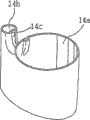
As mentioned above, in order to form PET bottle, at first form test tube shaped preformed member 10 with the handle that is formed on the body by injection blow molding method (more preferably, the injection drawing blow method).As shown in the figure, adopt type cavity mould 3 by making preformed member 10 form the test tube shape at core 5 surrounding injection resins, described type cavity mould is an injection molding.At this moment, injection molding has the gap that is formed between core 5 and the type cavity mould 3, and this gap is used to form test tube shaped preformed member 10, and the cast gate 3a by type cavity mould 3 injects the gap with resin and fills this gap like this, thereby forms preformed member 10.Core 5 is provided with the neck mould 4 of separated into two parts 4a and 4b at an upper portion thereof and forms the inlet of bottle.Molded preformed member 10 is separated with core 5 with type cavity mould 3.The preformed member 10 that separates with neck module 4 is shown among Fig. 3.
Fig. 4 is a perspective view, show the general structure of device that has the PET bottle of the handle that is formed on the body by injection-blow molding manufactured according to the present invention, and Fig. 5 is the vertical view that shows device shown in Figure 4.
With reference to figure 4 and Fig. 5, device 100 by injection-blow molding manufactured PET bottle according to the present invention comprises preformed member heating cabinet 21, manipulator 23, armature 20, preformed blowing mould 40, blowing mould 50, cutting die 60, and embedding injection molding 70, wherein, preformed member heating cabinet 21 receives and heats a plurality of preformed members 10, manipulator 23 is used to transmit the preformed member that has heated 10 from preformed member heating cabinet 21, the preformed member that has heated 10 that armature 20 receives from manipulator 23, and preformed member is sent to each stage of the process of making the PET bottle, blowing mould 50 has handle and forms part, cutting die 60 has the mold and punching head as cutter sweep, and embed injection molding 70 as coupling apparatus, wherein, preformed blowing mould 40, blowing mould 50, cutting die 60 and embedding injection molding 70 are positioned at the below of armature 20 and separate with preset distance each other on supporting seat 25, so that carry out continuous operation by the rotation of armature 20.In addition, this device is provided with a series of servicing units in the side of supporting seat 25, for example injector 72, be used to conveyer 80 that transmits finished product pet container 19 etc.Especially, it is porose 62 that cutting die 60 forms in its side, and mold and punching head 61 (referring to (a) among Figure 14 to (c)) inserts in this hole.Injector 72 is positioned at the side that embeds injection molding 70.Although the structure of Fig. 4 and device shown in Figure 5 is based on the blow moulding that adopts two-stage type injection-blow molding, undoubtedly, the present invention also is applicable to one-level formula injection blow molding method.
Below will be at each step, illustrate that the manufacturing according to injection-blow molding device of the present invention by as shown in Figure 4 and Figure 5 has the process of the PET bottle of the handle that is formed on the body.
Fig. 6 to Figure 10 is a perspective view, be presented at the product that each stage obtained in the injection-blow molding process according to the embodiment of the invention 1 in proper order, this injection-blow molding process is used to form the PET bottle with the handle that is formed on the body, (a) is the perspective view of the product that forms in each in stage in every secondary figure, and (b) is the perspective view of the product bottom that cuts off of the mid portion from product.
Figure 11 to Figure 15 is a perspective schematic view, is presented at according to employed device of each stage in the injection-blow molding process of the embodiment of the invention 1, and this injection-blow molding process is used to form the PET bottle with the handle that is formed on the body.
(1) first step
With reference to figure 4 and Fig. 5, after a plurality of preformed members 10 are received in preformed member heating cabinet 21 and heat, these preformed members 10 are by the order clamping, be delivered to armature 20 one by one by manipulator 23 then, make the preformed member that will heat be installed in the pre-position of below, armature 20 bottoms.Then, armature 20 rotates to predetermined angular, and the corresponding preformed member 10 that will be installed in armature 20 belows is placed in the preformed blowing mould 40, so that carry out the first blowing operation of the present invention.In preformed blowing mould 40 (referring to Figure 11), compressed air is blown into preformed member 10, the bar (not shown) that stretches simultaneously is from keeping the preformed member support 24 stretching preformed members 10 of preformed member 10.In the present embodiment, be used to make the PET bottle, the invention is not restricted to this method, and obviously, also can use injection blow molding method although the injection drawing blow method is shown as.
By this first blowing operation, form first pet container 13 as shown in Figure 7, this first pet container 13 has the oval hollow space 13a (referring to Fig. 7) that is formed at its central authorities.This is for following purpose: promptly, provide suitable shape to be used for by the handle portion on series of formed (molded) the process formation PET bottle that the following describes.Yet, should be appreciated that, the invention is not restricted to aforesaid ellipse.Figure 12 has shown first pet container 13 that produces after the first blowing operation.
According to present embodiment, because the PET bottle has oval hollow space therein, this ellipse hollow space has directionality in a circumferential direction, and handle is set in a part of PET bottle, therefore, preferably when on blowing mould 40,50,60 of the present invention and 70, preformed member 10 being installed, preformed member 10 is installed on blowing mould 40,50,60 and 70 with identical direction.This can fix by the direction that makes the PET bottle that is installed in armature 20 belows and realize.As an example, can form the groove (not shown) in the pre-position of the neck of preformed member 10, make when armature 20 clamping preformed members 10, allow the predetermined portions grasping of below, armature 20 bottoms to be formed at groove on the neck of preformed member 10, avoiding the PET bottle below armature 20 bottoms, to rotate, thereby allow the preformed member 10 of PET bottle accurately to be positioned in each blowing mould.
Simultaneously, when the preformed member 10 that will have circular hollow space as shown in Figure 6 formed first pet container 13 (referring to Fig. 7) that has oval hollow space as mentioned above, preformed member must form had homogeneous thickness.As a kind of method that realizes this purpose, can preformed member be heated by such mode: promptly, with than in the higher degree heating preformed member of periphery corresponding in the preformed member with the ellipsoid major axis of first pet container 13 after the blowing preformed member with the blowing preformed member after the corresponding periphery of ellipsoid minor axis of first pet container 13, change with formation temperature on circumference (rotation) direction of preformed member, make the periphery corresponding in the preformed member like this than extending manyly with the corresponding periphery of ellipsoid major axis in the preformed member, thereby make the hollow space of the pet container of winning have the uniform elliptical shape of thickness with the ellipsoid minor axis.
Preferably, when in the first blowing operation, forming first pet container 13, first pet container 13 is formed 60% to 80% of finished product PET bottle design volume.In addition, for fear of product cooling, suitably temperature of control first blowing mould 40 when second blowing of following the first blowing operation is operated.
(2) second steps
Next, after the first oval pet container 13 that the first blowing operation is formed is installed in the blowing mould 50 with handle formation part, carry out the second blowing operation to form second pet container 15 as shown in Figure 8.In the second blowing operation, by the both sides of moulding ledge 51 compressions by the predetermined portions of the body of the first oval pet container 13 of the first blowing operation formation, described moulding ledge is formed on the inner surface of half module to form part as handle, be used on first pet container 13, forming handle portion, undertaken stretching the second time by the remainder of blowing simultaneously the body of first pet container 13.Figure 13 has shown second pet container 15 that draws off after the second blowing operation.Adopt this second blowing operation, the body of second pet container 15 forms finished product PET bottle pattern.
At this moment, the first oval pet container 13 that stretches first in the first blowing operation is very thin, and is subjected to the influence of exterior temperature change easily.Especially, consider handle portion,, therefore must suitably control the temperature of blowing mould 50 with handle formation part so can experience the cooling phenomenon that causes temperature to reduce fast by mold component 51 compressions.In addition, carry out continuously after first pet container, and the tensility of first pet container is different from preformed member 10, therefore must changes the temperature that is used for stretched container first and blow pressure because second blowing operates in to stretch first.
In addition, in order to ensure like this: promptly, cut off in Shuo Ming the process below after the compression section 15b of handle portion of second pet container 15, the end 17c (referring to Fig. 9) that stays the cut-off parts in the handle portion is attached on the embedding injection portion 19c (referring to Figure 10) that forms by the embedding injection process as cohesive process, preferably, the surface of each moulding ledge 51 (referring to Figure 13) is formed out-of-flatness (irregularities), and this end 17c (referring to Figure 15) that causes staying the cut-off parts in the handle portion is at a distance of broadening a little each other.
(3) the 3rd steps
Next, when forming second pet container 15 by the second blowing operation, second pet container 15 is formed with the handle portion with depression and protruding features at an one part place, and this handle portion will form handle after the manufacturing of finishing the PET bottle.That is to say,, therefore must be removed by cutting because the compression section 15b (referring to Fig. 8) of handle portion does not separate fully.For this purpose, in the cutting die 60 that second pet container 15 is sent to as shown in figure 14 after, will carry out the 3rd step of the present invention.As a reference, in (c), be the perspective view that shows the general structure of cutting die 60 at (a) of Figure 14 (a), (b) be the horizontal sectional view of cutting die 60 shown in (a) among Figure 14, and (c) be its longitdinal cross-section diagram.
At this moment, have under the situation of heavy wall at second pet container 15, it will be very effective in the end of mold and punching head 61 heater 61a being installed separately.At this moment, preferably, the temperature of heater 61a is in 260 ℃ to 300 ℃ the scope, and must suitably control this temperature to avoid forming filament or filament.And, for fear of cutting part crystallization on every side, preferably, carry out cutting process as quickly as possible.After cutting process, the end 17c that stays the cut-off parts in the handle portion after the cut-out compression section may partly broaden.
When the compression section of handle portion is cut off by mold and punching head 61 when being heated by the heater 61a that is provided in mold and punching head 61 ends, cut-off parts can melt a little by the heat of heater 61a, and rust, thereby form noncrystalline part (referring to 17c among Figure 15).This noncrystalline part is used for improving the joint efficiency of another PET part that will introduce with following embedding injection process.
(4) the 4th steps
At this moment, as if can operate like this: promptly, use mold and punching head 61, heat and compress staying cut-off parts in the handle portion after the cutting process, thereby the end of staying the cut-off parts in the handle portion is bonded to each other.Yet,, therefore be difficult to make the combination of PET material by heating and compression because the PET material that stretches by the blowing process has fixing molecularly oriented.In addition, even carry out combination by this way, bond strength also is not enough to allow the finished product bottle to fill some article, for example liquid.Therefore; gratifying in order to ensure obtaining in conjunction with effect; preferably; after the cutting process in the 3rd step; in the 4th step, carry out combination and handle staying cutting part in the handle portion, rather than by with both sides that cutting process during the 3rd goes on foot side by side compresses cutting part the end of staying the cutting part in the handle portion being combined.
Handle (binder-treatment) about the combination of carrying out at the cutting part of staying in the handle portion after the cutting process, after being sent to as shown in figure 15 embedding injection molding 70, the 3rd pet container 17 that will be as shown in Figure 9 carried out for the 4th step, wherein the 3rd pet container 17 has been removed compression section 15b from handle portion, embeds injection molding 70 as coupling apparatus.
As a reference, in Figure 15, be the horizontal sectional view that show to embed injection molding 70 (a), (b) be its longitdinal cross-section diagram, and (c) be the enlarged drawing of part A, embed wherein that injection moulding carries out under the state that the half module that embeds injection molding 70 is engaged with each other.
As shown in the figure, in the 4th step of the present invention, injector 72 is positioned at the side that embeds injection molding 70, and the line of cut on the end 17c (referring to Fig. 9) of the cutting part in the handle portion of staying the 3rd pet container 17 carries out injection moulding by injector 72.
When the 3rd pet container 17 is installed in the embedding injection molding 70, stay the both sides of the mid portion 17d of the cut-off parts in the handle portion by embedding predetermined portions 71 (referring to Figure 15) compression that is used as compression element in the injection molding 70, thus avoid when embedding injection moulding encapsulant by the slot leakage between the mid portion 17d in the 17b of space.Simultaneously, seal the end 17c of the handle portion of the 3rd pet container 17 by embedding injection moulding.That is to say, space a and b shown in Figure 15 are filled with encapsulant, thereby for the inner periphery of handle portion 19d provides level and smooth three-dimensional shape, during with the handle of convenient user's grasping PET bottle, the grasping that the inner periphery of handle portion 19d is provided convenience for the PET bottle.At this moment, the size that determine to embed injection moulding part 19c to be keeping thickness and the consistent constant intensity of shape with bottle, thereby the miscellaneous function of reinforcement handle portion is provided.
Has the injection moulding of embedding part 19c by embedding injection molding 70 the 4th molded pet containers 19, and become finished product PET bottle, embedding injection moulding part 19c is formed at cutting process and stays afterwards around the end 17c of the cut-off parts in the handle portion of the 3rd pet container 17.
At this moment, in conjunction with processing, the 4th step can be undertaken by ultrasonic bonding, but not embedded injection moulding about the another kind of staying the cut-off parts in the handle portion after the cutting process.Ultrasonic bonding is such method: promptly, after producing heat by ultrasonic vibration on lap, with the method that the lap of plastics is welded to one another, this method is not only applicable to the combination of thin material and is applicable to the combination of thick plastic material.Especially, under the situation of PET material, can not or be difficult to hot plate welding (heat plate bonding), pulse welding or high-frequency welding are applied to the combination of PET material, but can connect its using ultrasound wave soldering by using high-frequency generator, vibrator, instrument soldering tip (tool horn) etc.
The same with the cohesive process that uses above-mentioned embedding injection molding to carry out, compress the both sides of mid portion 17d (referring to Fig. 9) of the handle portion of the 3rd pet container 17, on lap, produce dither, thereby make lap be heated and be welded to one another together.
Embodiment 2
According to embodiment 1, the method for making the PET bottle comprises the steps: to carry out the first blowing operation, and the preformed member 10 that compressed air is blown in the preformed blowing mould 40 is interior so that form the first hollow pet container 13 (first step); Carry out the second blowing operation, compressed air is blown in first pet container 13 so that form second pet container 15 (second step) in the blowing mould 50 with moulding ledge 51; Cut off the compression section 15b of second pet container 15 so that form the 3rd pet container 17 (the 3rd step); And in conjunction with staying the end 17c in the handle portion of the 3rd pet container 17 so that form the 4th pet container (in embedding process of injection molding, carry out in conjunction with the time, the 4th pet container has shape as shown in figure 10, and when in the supersonic welding termination process, carry out in conjunction with the time, the 4th pet container has and similar shapes shown in Figure 17).
Figure 16 and Figure 17 are perspective views, show respectively by according to the 3rd step of the method for the embodiment of the invention 2 and the product of the 4th step acquisition.
With reference to Figure 16 and Figure 17, except the 3rd step and the 4th among the embodiment 1 goes on foot and (more particularly, the supersonic welding termination process outside) the order, to comprise and the step identical according to the method for embodiment 1 according to the method for embodiment 2.That is to say, in the 3rd step according to the method for embodiment 2, make the both sides combination of the compression section 15b in the handle portion of second pet container 15 shown in Figure 8 by the supersonic welding termination process, thereby form the 3rd pet container 16 as shown in figure 16, in the 4th step of embodiment 2, cut off the compression bound fraction 16b of the handle portion of the 3rd pet container 16, thereby form the 4th pet container 18 as shown in figure 17.
According to embodiment 2, the second and the 3rd step of this method can carry out separately.As selection, by blowing mould 50 (referring to Figure 13), the second and the 3rd step of this method also can be used to form second pet container 15 simultaneously, the ultrasonic vibrator (not shown) of the far-end that described blowing mould 50 one of has in the moulding ledge 51 that is provided in blowing mould 50.Under latter event, can obtain to reduce the effect of production time and manufacturing cost.
Figure 18 is a perspective view, and the product according to the 5th step acquisition of the method for the embodiment of the invention 3 is passed through in demonstration.Embodiment 3 comprises five steps.
Identical according to the first step of the method for embodiment 3 with the first step according to the method for embodiment 1 and 2.That is to say, after preformed member being installed in the preformed blowing mould 40, carry out the first blowing operation.
Different with second step according to the method for embodiment 1 and 2, in second step according to the method for embodiment 3, first pet container 13 by the blowing operation fully expansion be finished product PET bottle pattern.According to embodiment 3, this method comprises the 5th other step, and the 5th step was used to blow operation pet container is stretched as finished product PET bottle pattern.
That is to say, obtains to go on foot by revising second step according to the method for embodiment 1 and 2 according to second of the method for embodiment 3, wherein, operate to carry out second blowing by compressed air being blown into first pet container 13 to following degree, thereby form second pet container of 70% to 90% shape of volume with finished product PET bottle pattern, described degree is: when the 50 pairs of handle portions of blowing mould that have a moulding ledge 51 in employing compressed, the handle portion of first pet container 13 can not be out of shape.
Although according to third and fourth step of the method for embodiment 3 with go on foot identical according to third and fourth of the method for embodiment 1 or 2, but, according to the blowing operation that in the 5th step as described below pet container is formed finished product PET bottle, preferably, the operating temperature that in third and fourth step, keeps the first step.More particularly, the same with embodiment 1, in the 3rd step, cut off the compression section 15b of second pet container, and in the 4th step, make the end 17c combination of the cut-off parts in the handle portion of staying the 3rd pet container by embedding injection or ultrasonic bonding.As selection, the same with embodiment 2, in the 3rd step, make the both sides combination of compression section 15b, and in the 4th step, cut off compression section 16b by ultrasonic bonding.
In the 5th step according to the method for embodiment 3, in that the 4th pet container is (similar to Figure 10 or container shown in Figure 17, but be under the state of 70% to 90% shape of the volume that is blow molded finished product PET bottle pattern) be installed in the blowing mould (not shown) after, carry out other blowing operation to form the 5th pet container 14 as shown in figure 18, wherein this blowing mould has finished product PET bottle shape and has handle formation part, and this handle forms part will penetrate the body of pet container in the 5th step.Compare with the blowing mould 50 with moulding ledge 51 shown in Figure 13, the blowing mould that is used for the 3rd blowing operation of embodiment 3 is with the difference of blowing mould 50: form moulding ledge partly as the handle on the half module that is formed at blowing mould and contact with each other by opening 19d or 18d as Figure 10 or handle portion shown in Figure 17.If in third and fourth step, finish after the cohesive process and in the 5th step, blow operation, then can obtain to provide the Figure 10 that embeds in the container or the effect of bound fraction 19c shown in Figure 17 or 18c.The 5th pet container that provides by the 5th step after for example finishing cohesive process by embedding injection moulding has been provided Figure 18, wherein the 5th pet container 14 has the embedding injection moulding part 19c shown in Figure 10 that embeds in the container, and handle portion has the shape of penetrating 14d.
Embodiment 4
Embodiment 4 goes on foot by the 3rd of 2 second step and embodiment 2 in conjunction with the embodiments and forms, wherein, in second step of embodiment 2, have handle formation blowing mould 50 partly and carry out the second blowing operation, in the 3rd step of embodiment 2, make compression section 15b combination by ultrasonic bonding by use.Specifically, embodiment 4 is characterised in that: comprise that by use handle forms the handle formation device of part and is installed in the ultrasonic brazing unit that handle forms segment distal, carries out formation and the combination of the compression section 15b in the handle portion simultaneously.
Making in the method for the PET bottle with the handle that is formed on the body according to embodiment 4, the first step is identical with the first step of embodiment 1 to 3.That is to say, in the first step of this method, after preformed member 10 being installed in the preformed blowing mould 40, carry out the first blowing operation.
In second step, the formation of compression section 15b in the handle portion and combination are carried out as follows simultaneously: promptly, compress the both sides of first pet container, comprise that by use the handle formation device that handle forms partly carries out simultaneously ultrasonic bonding with the ultrasonic brazing unit that is installed in handle formation segment distal on compression section 15b.Similar by second pet container that second step formed to container shown in Figure 16.
In the 3rd step, cut off the compression bound fraction 16b of handle portion.
In the 4th step, in that the 3rd pet container is (similar to container shown in Figure 17, but be under the state that is blow molded to 60% to 80% shape of the volume of finished product PET bottle pattern) carry out the second blowing operation after being installed in the blowing mould (not shown), wherein this blowing mould has finished product PET bottle shape and has handle formation part, and this handle forms the body that part will penetrate pet container.In the 4th step, the 4th pet container that formation has finished product PET bottle shape is (the same with pet container shown in Figure 180, the 4th pet container also has embedded part 14c, but is that with the difference of pet container shown in Figure 180 embedded part 14c combines by ultrasonic bonding).
Although the embodiment above having illustrated about the PET resin, obviously, the present invention is applicable to that also the plastic material outside the use PET resin makes various bottles.
Industrial applicibility
From top explanation obviously as seen, according to the present invention, form by continuous injection blow molding method and to have the handle that is formed on the body and can not be by the PET bottle of traditional extrusion-blown modling manufactured, ease of use is provided thus, improve the manufacturing efficient of PET bottle with the handle that is formed on the body, can eliminate and reuse relevant work and the cost of handle that constitutes by the plastic material that is different from the bulk material in the conventional P ET container, and avoid the environmental pollution and the economic loss that cause because of the handle of discarded conventional P ET container.
Although injection blow molding method is the suitable method that forms the PET bottle with the handle that is formed on the body, this is because this method has the cause of the advantage that can make the uniform container of thickness, but this method also is applicable to the various containers that are made of the plastic material outside the PET resin, and obviously, the shape of container is not limited to ellipse.
Although disclose the preferred embodiments of the present invention for illustrational purpose, but, one skilled in the art will appreciate that to carry out various modifications, increase and be equal to and replace and do not break away from as disclosed scope of the present invention of appended claims and marrow.
Claims (9)
1. device that is used to make the PET bottle with the handle that is formed on the body comprises:
The preformed blowing mould, it is used for air is blown into preformed member, so that described preformed member is a finished form with the estimated rate expansion, thereby allows the compression handles part;
Blowing mould, it has handle and forms part, is used to compress the both sides of described bottle to form described handle portion;
Cutter sweep, it comprises mold and punching head, is used to cut off the compression section that is formed the described handle portion of part compression by described handle;
Coupling apparatus, it is used for staying after being combined in the compression section that cuts off described handle portion the cut-off parts of described handle portion; And
Conveyer, it is used for transmitting described preformed member or described molded PET bottle in the neck of the neck of the described preformed member of clamping or described molded PET bottle,
Wherein, the embedding injection molding of described coupling apparatus for the end of described cut-off parts being bonded to each other by the embedding injection, described embedding injection molding comprises compression element, and described compression element is used for being compressed in the both sides of the mid portion of the described cut-off parts of staying described handle portion after the compression section that cuts off described handle portion.
2. device as claimed in claim 1 also comprises having the doleiform blowing mould that handle forms part, and described handle forms part and constitutes: the body that penetrates described bottle in two rear flank of the described bottle of compression.
3. coupling apparatus, it is included in the device that is used for making the PET bottle with the handle that is formed on the body, is used for staying after being combined in the compression section that cuts off handle portion the cut-off parts of described handle portion, wherein,
The embedding injection molding of described coupling apparatus for the end of described cut-off parts being bonded to each other by the embedding injection, described embedding injection molding comprises compression element, and described compression element is used for being compressed in the both sides of the mid portion of the described cut-off parts of staying described handle portion after the compression section that cuts off described handle portion.
4. a manufacturing has the method for the PET bottle of the handle that is formed on the body, comprises the steps:
A) after preformed member being installed in the preformed blowing mould, carry out the first blowing operation, compressed air is blown in the described preformed member that produces by injection moulding, so that form the first hollow pet container;
B) after in described first pet container being installed in blowing mould with handle formation part, carry out the second blowing operation, compressed air is blown in described first pet container, so that form second pet container, described second pet container has the handle portion that is formed at its presumptive area place;
C) compression section of the described handle portion of described second pet container of cut-out is so that form the 3rd pet container; And
D) make cut-off parts combination in the described handle portion of staying described the 3rd pet container after the step c), so that form the 4th pet container.
5. method as claimed in claim 4, wherein,
In step d), in embedding injection molding, make cut-off parts in the described handle portion of staying described the 3rd pet container be combined into predetermined thickness to form described the 4th pet container by embedding injection moulding.
6. method as claimed in claim 4, wherein,
When described second pet container had big thickness, the mold and punching head that has the heater that is installed in the mold and punching head end by use carried out step c).
7. one kind has in the process of PET bottle of the handle that is formed on the body in conjunction with the method for the cut-off parts in the handle portion of staying pet container in manufacturing, comprising:
A) adopt the compression element that comprises in the embedding injection molding to be compressed in the both sides that the compression section that cuts off described handle portion is stayed the mid portion of the described cut-off parts in the described handle portion afterwards; And
B) adopt described embedding injection molding the end of described cut-off parts to be bonded to each other by embedding injection.
8. a manufacturing has the method for the PET bottle of the handle that is formed on the body, comprises the steps:
A) after preformed member being installed in the preformed blowing mould, carry out the first blowing operation, compressed air is blown in the described preformed member that produces by injection moulding, so that form the first hollow pet container;
B) after in described first pet container being installed in blowing mould with handle formation part, carry out the second blowing operation, compressed air is blown in described first pet container, so that form second pet container, described second pet container has the handle portion that is formed at its presumptive area place;
C) compression section of the described handle portion of described second pet container of cut-out is so that form the 3rd pet container;
D) make cut-off parts combination in the described handle portion of staying described the 3rd pet container after the step c), so that form the 4th pet container; And
E) after being installed in described the 4th pet container in the doleiform blowing mould, compressed air is blown in described the 4th pet container, so that form the 5th pet container, the handle that described doleiform blowing mould has the body that penetrates described the 4th pet container after blowing forms part.
9. method as claimed in claim 8, wherein,
In step d), in embedding injection molding, make the cut-off parts of the described handle portion of described the 3rd pet container be combined into constant thickness and form described the 4th pet container by embedding injection moulding.
Applications Claiming Priority (2)
| Application Number | Priority Date | Filing Date | Title |
|---|---|---|---|
| KR1020030093910 | 2003-12-19 | ||
| KR1020030093910A KR100650155B1 (en) | 2003-12-19 | 2003-12-19 | Method for manufacturing PET bottle with handle by injection blow molding and PET bottle manufactured by it |
Publications (2)
| Publication Number | Publication Date |
|---|---|
| CN1894082A CN1894082A (en) | 2007-01-10 |
| CN100540268C true CN100540268C (en) | 2009-09-16 |
Family
ID=36616548
Family Applications (1)
| Application Number | Title | Priority Date | Filing Date |
|---|---|---|---|
| CNB2004800378560A Expired - Fee Related CN100540268C (en) | 2003-12-19 | 2004-12-17 | Manufacturing has the apparatus and method of PET bottle of handle and the PET bottle of making by this apparatus and method |
Country Status (10)
| Country | Link |
|---|---|
| US (1) | US20070145646A1 (en) |
| EP (1) | EP1694491A4 (en) |
| JP (1) | JP4474420B2 (en) |
| KR (1) | KR100650155B1 (en) |
| CN (1) | CN100540268C (en) |
| AU (1) | AU2004299414B2 (en) |
| BR (1) | BRPI0417563A (en) |
| CA (1) | CA2547638C (en) |
| RU (1) | RU2323088C2 (en) |
| WO (1) | WO2005058580A1 (en) |
Families Citing this family (26)
| Publication number | Priority date | Publication date | Assignee | Title |
|---|---|---|---|---|
| EP2103413B1 (en) * | 2008-03-18 | 2012-08-01 | The Procter & Gamble Company | A process for making a stretch-blow moulded container having an integrally moulded handle |
| DE102008036364A1 (en) * | 2008-08-05 | 2010-02-18 | Khs Ag | Method for producing container cells |
| FR2936733A1 (en) * | 2008-10-07 | 2010-04-09 | Sidel Participations | IMPROVEMENTS IN THE FORMING OF BOXED CONTAINERS |
| JP5220660B2 (en) * | 2009-03-03 | 2013-06-26 | 本多プラス株式会社 | Bottle-type accessory and manufacturing method thereof |
| ES2378746T3 (en) * | 2009-09-04 | 2012-04-17 | The Procter & Gamble Company | Process to produce a blow molded and stretched container that has an integrally molded handle |
| FR2950282B1 (en) * | 2009-09-23 | 2016-12-09 | Tecsor | PROCESS FOR PRODUCING BY BLOWING A CONTAINER WITH AN INTEGRATED HANDLE, CONTAINING OBTAINED |
| KR101273597B1 (en) * | 2010-06-14 | 2013-06-11 | 남중희 | Bottles |
| JP5220889B2 (en) * | 2011-06-16 | 2013-06-26 | 本多プラス株式会社 | Bottle-type accessory and manufacturing method thereof |
| CN102923934B (en) * | 2011-08-08 | 2015-07-15 | 江苏豪迈照明科技有限公司 | Die for preparing fluorescent lamp tube, and method for preparing lamp tube through using it |
| CA2855150C (en) | 2011-11-15 | 2020-03-24 | Amcor Limited | Container formed via plural blow molding |
| US9022776B2 (en) | 2013-03-15 | 2015-05-05 | Graham Packaging Company, L.P. | Deep grip mechanism within blow mold hanger and related methods and bottles |
| US9254937B2 (en) | 2013-03-15 | 2016-02-09 | Graham Packaging Company, L.P. | Deep grip mechanism for blow mold and related methods and bottles |
| CN103331900B (en) * | 2013-05-30 | 2015-07-29 | 佛山市旭捷包装技术有限公司 | A kind ofly blow heat-resisting PET bottle production technology and special adjusting device thereof for twice |
| EP2823949A1 (en) * | 2013-07-08 | 2015-01-14 | ISP Technology AG | Plastic connection seam, plastic bottle with seam and method for their preparation |
| CN105480541A (en) * | 2015-12-02 | 2016-04-13 | 王高杨 | Plastic container with through hole, and production method thereof |
| CH712555A1 (en) | 2016-06-06 | 2017-12-15 | Alpla Werke Alwin Lehner Gmbh & Co Kg | Stretch-blown plastic container with an integrally formed handle region and production method for the plastic container. |
| CN107116778B (en) * | 2017-06-13 | 2023-06-13 | 厦门翔达川实业有限公司 | Integrated forming die for manufacturing plastic tray with base and using method thereof |
| FR3069182A1 (en) | 2017-07-21 | 2019-01-25 | Ublo | MACHINE FOR MANUFACTURING PLASTIC ARTICLES BY BLOWING. |
| JP7039307B2 (en) * | 2018-02-02 | 2022-03-22 | テルモ株式会社 | Manufacturing method of medical liquid storage container body |
| FR3080055A1 (en) * | 2018-04-16 | 2019-10-18 | Sidel Participations | MOLDING UNIT WITH DECENTRE COL PASSAGE ORIFICE |
| WO2020261122A1 (en) * | 2019-06-28 | 2020-12-30 | Discma Ag | Reduced material container and system and method of forming the same |
| WO2021209786A1 (en) * | 2020-04-14 | 2021-10-21 | Terekas, Uab | Method of manufacture of face protection device and face protection device |
| KR102253803B1 (en) * | 2020-10-20 | 2021-05-18 | 강태윤 | An apparatus for injection blow molding and manufacturing method of lamp cover using the same |
| CN113580542A (en) * | 2021-08-05 | 2021-11-02 | 肇庆市金腾机械实业有限公司 | Intelligent identification bottle blowing system |
| CH718924A1 (en) * | 2021-08-27 | 2023-02-28 | Alpla Werke Alwin Lehner Gmbh & Co Kg | Stretch blow molded plastic container with a handle formed on the container body and method of making. |
| CN116425403A (en) * | 2023-04-13 | 2023-07-14 | 广东金水晶玻璃股份有限公司 | Demoulding device for processing glass bottle and jar |
Family Cites Families (25)
| Publication number | Priority date | Publication date | Assignee | Title |
|---|---|---|---|---|
| US2936920A (en) * | 1957-05-03 | 1960-05-17 | Owens Illinois Glass Co | Molded articles having molding seams or the like formed on the base thereof |
| US3366290A (en) * | 1966-09-08 | 1968-01-30 | Mojonnier Inc | Plastic container with integral handle |
| US3499071A (en) * | 1967-06-19 | 1970-03-03 | Procter & Gamble | Apparatus for in-mold removal of flash |
| US3740181A (en) * | 1971-05-17 | 1973-06-19 | Owens Illinois Inc | Apparatus for blow molding plastic articles |
| US3754489A (en) * | 1971-06-02 | 1973-08-28 | Dove J B Inc | Smokeless cut-off blade for plastic wrapping film |
| US3892830A (en) * | 1972-04-10 | 1975-07-01 | Phillips Petroleum Co | Precise temperature adjustment of reheated parison preforms |
| US3817390A (en) * | 1972-08-18 | 1974-06-18 | A Maruniak | Non-metallic, one-piece filter strainer head |
| US4038006A (en) * | 1974-06-04 | 1977-07-26 | Farrell Patent Company | Apparatus for making a blow molded container with hollow handle and method of making |
| US3928522A (en) * | 1974-06-04 | 1975-12-23 | Farrell Patent Co | Method of making a blow molded container with hollow handle |
| US4123217A (en) * | 1974-11-30 | 1978-10-31 | Maschinenfabrik Johann Fischer | Apparatus for the manufacture of a thermoplastic container with a handle |
| US4320789A (en) * | 1979-04-09 | 1982-03-23 | Baxter Travenol Laboratories, Inc. | Collapsible solution container |
| US4291915A (en) * | 1979-04-26 | 1981-09-29 | Jeanette Cox | Combined suitcase and child's safety seat |
| US4522779A (en) * | 1983-11-28 | 1985-06-11 | Owens-Illinois, Inc. | Method for production of poly(ethylene terephthalate) articles |
| US5057266A (en) * | 1988-07-21 | 1991-10-15 | Sabel Plastechs, Inc. | Method of making a hollow polyethylene terephthalate blow molded article with an integral external projection such as a handle |
| US5360661A (en) * | 1989-04-17 | 1994-11-01 | Georgia Tech Research Corp. | Towpregs from recycled plastics by powder fusion coating |
| JPH0390331A (en) * | 1989-09-01 | 1991-04-16 | Nissei Ee S B Kikai Kk | Thin-wall synthetic resin container with handle and manufacture thereof |
| DE3939970A1 (en) * | 1989-12-02 | 1991-06-06 | Tetra Pak Gmbh | PACKAGE FOR FLOWABLE FILLING MATERIAL WITH CIRCULAR SEAM |
| US5874141A (en) * | 1996-04-03 | 1999-02-23 | Inoac Packaging Group, Inc. | Injection/blow molded plastic container and method |
| FR2757245B1 (en) * | 1996-12-12 | 1999-02-19 | Hutchinson | DEVICE FOR FIXING AT LEAST ONE FLUID PIPE ON A SUPPORT |
| JP4623826B2 (en) * | 1997-09-09 | 2011-02-02 | ビー・アンド・アール・インダストリーズ・ピーティワイ・リミテッド | Container with pre-formed handle, preform, and method for manufacturing the same |
| US6648623B2 (en) * | 1999-02-05 | 2003-11-18 | Sidel, Inc. | Quick change blow mold shell assembly |
| US6978802B2 (en) * | 2001-03-08 | 2005-12-27 | Toyoda Gosei Co., Ltd. | Fuel tank and manufacturing method thereof |
| US6733716B2 (en) * | 2001-05-21 | 2004-05-11 | Sabel Plastechs Inc. | Method of making a stretch/blow molded article (bottle) with an integral projection such as a handle |
| EP2243537B1 (en) * | 2002-10-28 | 2016-05-04 | Donaldson Company, Inc. | Air cleaner |
| JP6077960B2 (en) * | 2013-07-24 | 2017-02-08 | 日本電子株式会社 | Spherical aberration correction device, spherical aberration correction method, and charged particle beam device |
-
2003
- 2003-12-19 KR KR1020030093910A patent/KR100650155B1/en not_active IP Right Cessation
-
2004
- 2004-12-17 CA CA2547638A patent/CA2547638C/en not_active Expired - Fee Related
- 2004-12-17 BR BRPI0417563-8A patent/BRPI0417563A/en not_active IP Right Cessation
- 2004-12-17 WO PCT/KR2004/003341 patent/WO2005058580A1/en active IP Right Grant
- 2004-12-17 CN CNB2004800378560A patent/CN100540268C/en not_active Expired - Fee Related
- 2004-12-17 JP JP2006545241A patent/JP4474420B2/en active Active
- 2004-12-17 RU RU2006119980/12A patent/RU2323088C2/en not_active IP Right Cessation
- 2004-12-17 AU AU2004299414A patent/AU2004299414B2/en not_active Ceased
- 2004-12-17 US US10/583,536 patent/US20070145646A1/en not_active Abandoned
- 2004-12-17 EP EP04808472A patent/EP1694491A4/en not_active Withdrawn
Also Published As
| Publication number | Publication date |
|---|---|
| KR20050062909A (en) | 2005-06-28 |
| US20070145646A1 (en) | 2007-06-28 |
| KR100650155B1 (en) | 2006-11-27 |
| CA2547638A1 (en) | 2005-06-30 |
| CA2547638C (en) | 2010-06-15 |
| RU2323088C2 (en) | 2008-04-27 |
| WO2005058580A1 (en) | 2005-06-30 |
| AU2004299414A1 (en) | 2005-06-30 |
| EP1694491A1 (en) | 2006-08-30 |
| CN1894082A (en) | 2007-01-10 |
| RU2006119980A (en) | 2008-01-27 |
| EP1694491A4 (en) | 2012-02-08 |
| AU2004299414B2 (en) | 2007-07-12 |
| JP2007513814A (en) | 2007-05-31 |
| BRPI0417563A (en) | 2007-03-27 |
| JP4474420B2 (en) | 2010-06-02 |
Similar Documents
| Publication | Publication Date | Title |
|---|---|---|
| CN100540268C (en) | Manufacturing has the apparatus and method of PET bottle of handle and the PET bottle of making by this apparatus and method | |
| EP1827797B1 (en) | Method for manufacturing a plastic fuel tank with improved creep strength | |
| US5507999A (en) | Process for thermoforming plastic doors | |
| EP0153120A2 (en) | Laminated preform with internal barrier layer | |
| US4243620A (en) | Method of manufacturing an object in plastics material and object obtained thereby | |
| JPH0635150B2 (en) | Method for producing stretch-blown plastic bottle with handle | |
| CN101115606A (en) | Method for manufacturing containers through stretching and blow-molding and the containers manufactured thereof | |
| JPH0651340B2 (en) | Method and apparatus for extrusion blow molding polyethylene terephthalate products | |
| CN105121127A (en) | Method for producing a container and perforation device | |
| JPH0628893B2 (en) | A method for making blown polyethylene terephthalate blow molded articles with integral outer protrusions, for example handles. | |
| KR20050083196A (en) | Spiral plastic pipe and the manufacture method and manufacture device | |
| CN109311216A (en) | Plastic containers made of the stretch-blow of grip area with integrated composition and the manufacturing method for plastic containers | |
| JP4284786B2 (en) | Thin bottle manufacturing method | |
| JP2932454B2 (en) | Composite molded article and method for producing the same | |
| JP2860886B2 (en) | Molding method and molding die for molded articles composed of a plurality of different products | |
| JPS63290715A (en) | Manufacture of synthetic resin hollow molded product | |
| JP2000000880A (en) | Blow molding device and blow molding method | |
| JP7039307B2 (en) | Manufacturing method of medical liquid storage container body | |
| KR101555563B1 (en) | Manufacturing process for a delaminated bottle and molding apparatus using the same | |
| JPH0220413B2 (en) | ||
| RU2762305C2 (en) | Method and device for manufacturing insert for composite vessel used under pressure | |
| KR100436797B1 (en) | Piping system of a blow molding | |
| JP3243574B2 (en) | Blow forming method and apparatus for bent pipe joint | |
| KR100436798B1 (en) | Piping system of a blow molding | |
| KR100436800B1 (en) | Piping system of a blow molding |
Legal Events
| Date | Code | Title | Description |
|---|---|---|---|
| C06 | Publication | ||
| PB01 | Publication | ||
| C10 | Entry into substantive examination | ||
| SE01 | Entry into force of request for substantive examination | ||
| C14 | Grant of patent or utility model | ||
| GR01 | Patent grant | ||
| C17 | Cessation of patent right | ||
| CF01 | Termination of patent right due to non-payment of annual fee |
Granted publication date: 20090916 Termination date: 20121217 |