CN100508383C - Piezoelectric vibration piece and piezoelectric device - Google Patents
Piezoelectric vibration piece and piezoelectric device Download PDFInfo
- Publication number
- CN100508383C CN100508383C CNB2006100652903A CN200610065290A CN100508383C CN 100508383 C CN100508383 C CN 100508383C CN B2006100652903 A CNB2006100652903 A CN B2006100652903A CN 200610065290 A CN200610065290 A CN 200610065290A CN 100508383 C CN100508383 C CN 100508383C
- Authority
- CN
- China
- Prior art keywords
- electrode
- base portion
- shaker arm
- vibration piece
- piezoelectric vibration
- Prior art date
- Legal status (The legal status is an assumption and is not a legal conclusion. Google has not performed a legal analysis and makes no representation as to the accuracy of the status listed.)
- Active
Links
- 238000005538 encapsulation Methods 0.000 claims description 14
- 239000000463 material Substances 0.000 abstract description 3
- 230000005284 excitation Effects 0.000 abstract 1
- 238000000605 extraction Methods 0.000 description 14
- 210000000689 upper leg Anatomy 0.000 description 8
- 239000011651 chromium Substances 0.000 description 4
- 230000014509 gene expression Effects 0.000 description 4
- 239000010931 gold Substances 0.000 description 4
- 239000000758 substrate Substances 0.000 description 4
- 230000015572 biosynthetic process Effects 0.000 description 3
- VYZAMTAEIAYCRO-UHFFFAOYSA-N Chromium Chemical compound [Cr] VYZAMTAEIAYCRO-UHFFFAOYSA-N 0.000 description 2
- 238000004458 analytical method Methods 0.000 description 2
- 229910052804 chromium Inorganic materials 0.000 description 2
- 230000005684 electric field Effects 0.000 description 2
- 238000005530 etching Methods 0.000 description 2
- PCHJSUWPFVWCPO-UHFFFAOYSA-N gold Chemical compound [Au] PCHJSUWPFVWCPO-UHFFFAOYSA-N 0.000 description 2
- 229910052737 gold Inorganic materials 0.000 description 2
- 239000010453 quartz Substances 0.000 description 2
- VYPSYNLAJGMNEJ-UHFFFAOYSA-N silicon dioxide Inorganic materials O=[Si]=O VYPSYNLAJGMNEJ-UHFFFAOYSA-N 0.000 description 2
- WSMQKESQZFQMFW-UHFFFAOYSA-N 5-methyl-pyrazole-3-carboxylic acid Chemical compound CC1=CC(C(O)=O)=NN1 WSMQKESQZFQMFW-UHFFFAOYSA-N 0.000 description 1
- 239000002253 acid Substances 0.000 description 1
- 239000000853 adhesive Substances 0.000 description 1
- 230000001070 adhesive effect Effects 0.000 description 1
- 230000005540 biological transmission Effects 0.000 description 1
- 239000000919 ceramic Substances 0.000 description 1
- 239000013078 crystal Substances 0.000 description 1
- 238000010586 diagram Methods 0.000 description 1
- 238000001312 dry etching Methods 0.000 description 1
- 230000000694 effects Effects 0.000 description 1
- 238000005516 engineering process Methods 0.000 description 1
- 210000003414 extremity Anatomy 0.000 description 1
- 239000010436 fluorite Substances 0.000 description 1
- 239000011521 glass Substances 0.000 description 1
- 238000009434 installation Methods 0.000 description 1
- 239000011810 insulating material Substances 0.000 description 1
- GQYHUHYESMUTHG-UHFFFAOYSA-N lithium niobate Chemical compound [Li+].[O-][Nb](=O)=O GQYHUHYESMUTHG-UHFFFAOYSA-N 0.000 description 1
- 238000000034 method Methods 0.000 description 1
- TWNQGVIAIRXVLR-UHFFFAOYSA-N oxo(oxoalumanyloxy)alumane Chemical compound O=[Al]O[Al]=O TWNQGVIAIRXVLR-UHFFFAOYSA-N 0.000 description 1
- VYMDGNCVAMGZFE-UHFFFAOYSA-N phenylbutazonum Chemical compound O=C1C(CCCC)C(=O)N(C=2C=CC=CC=2)N1C1=CC=CC=C1 VYMDGNCVAMGZFE-UHFFFAOYSA-N 0.000 description 1
- 230000001105 regulatory effect Effects 0.000 description 1
- 238000007789 sealing Methods 0.000 description 1
- 238000005245 sintering Methods 0.000 description 1
Images


Classifications
-
- H—ELECTRICITY
- H10—SEMICONDUCTOR DEVICES; ELECTRIC SOLID-STATE DEVICES NOT OTHERWISE PROVIDED FOR
- H10N—ELECTRIC SOLID-STATE DEVICES NOT OTHERWISE PROVIDED FOR
- H10N30/00—Piezoelectric or electrostrictive devices
- H10N30/80—Constructional details
- H10N30/87—Electrodes or interconnections, e.g. leads or terminals
-
- H—ELECTRICITY
- H03—ELECTRONIC CIRCUITRY
- H03H—IMPEDANCE NETWORKS, e.g. RESONANT CIRCUITS; RESONATORS
- H03H9/00—Networks comprising electromechanical or electro-acoustic devices; Electromechanical resonators
- H03H9/15—Constructional features of resonators consisting of piezoelectric or electrostrictive material
- H03H9/21—Crystal tuning forks
-
- H—ELECTRICITY
- H10—SEMICONDUCTOR DEVICES; ELECTRIC SOLID-STATE DEVICES NOT OTHERWISE PROVIDED FOR
- H10N—ELECTRIC SOLID-STATE DEVICES NOT OTHERWISE PROVIDED FOR
- H10N30/00—Piezoelectric or electrostrictive devices
- H10N30/80—Constructional details
- H10N30/87—Electrodes or interconnections, e.g. leads or terminals
- H10N30/875—Further connection or lead arrangements, e.g. flexible wiring boards, terminal pins
Landscapes
- Chemical & Material Sciences (AREA)
- Crystallography & Structural Chemistry (AREA)
- Physics & Mathematics (AREA)
- Acoustics & Sound (AREA)
- Piezo-Electric Or Mechanical Vibrators, Or Delay Or Filter Circuits (AREA)
Abstract
A piezoelectric vibration piece includes a base made of a piezoelectric material; a plurality of vibration arms which is integrally formed with the base and extends in parallel; elongate grooves which are formed along longitudinal directions of the vibration arms; and excitation electrodes which include inner electrodes disposed in the elongate grooves and side electrodes disposed in side surfaces facing the inner electrodes, wherein widening portions in which the widths of the vibration arms are widened toward the base at a joint between the vibration arms of the base are formed, and the side electrodes are led to principal surfaces and side surfaces of the widening portions.
Description
Technical field
The present invention relates to piezoelectric vibration piece and in encapsulation and housing, accommodated the improvement of the piezoelectric device of piezoelectric vibration piece.
Background technology
Fig. 7 is the summary vertical view of an example of the piezoelectric vibration piece of representing that piezoelectric device in the past uses, and Fig. 8 is the summary cutaway view of the A-A line along Fig. 7.
In the drawings, piezoelectric vibration piece 1 forms illustrated profile by piezoelectrics such as etching quartz, has the base portion 2 of rectangle and from a pair of shaker arm 3,4 of base portion 2 right-hand extension to figure, interarea (positive and negative) at these shaker arms forms elongated slot 3a, 4a, and forms necessary driving electrode.
That is, being provided with on base portion 2 is electrode 5,6 heteropole, that be applied in driving usefulness voltage each other.
Electrode 5 be around to the elongated slot 3a that is located at shaker arm 3 inner face and with the opposed side 4b of inner face of the elongated slot 4a of shaker arm 4.
Electrode 6 is around to the inner face of the elongated slot 4a that is located on the shaker arm 4 by being located at the side electrode 6a on the opposed side 3b of inner face with the elongated slot 3a of shaker arm 3 and being located at base electrode 6b on the interarea of base portion 2, makes not and electrode 5 short circuits.
And, because electrode 6a is provided with electrode to the 2a of thigh portion around avoiding at shaker arm 3,4 of base electrode 6b from the side, so the interarea (positive and negative) at the sidewall 3c of shaker arm 3 forms the electrode 6c that is connected with side electrode 6a, and connects this electrode 6c and base electrode 6b.
Like this, at the electrode of each inner face of being located at elongated slot 3a, 4a be located between the electrode of each side 3b, 4b of shaker arm 3,4 and produce electric field, can reduce crystal impedance value (hereinafter referred to as " CI value "), so can make the piezoelectric vibration piece miniaturization.
; in the piezoelectric vibration piece of miniaturization like this; be not easy to carry out electrode recited above around, particularly because the width W 1 of the sidewall 3c of shaker arm 3 is very narrow and small, the electrode 6c that forms so do not contact with the electrode that is located at elongated slot 3a inner face on the interarea of sidewall 3c is very difficult.
Therefore, having proposed to utilize near the partial enlarged drawing that amplifies the root with shaker arm is piezoelectric vibration piece 10 (for example, with reference to patent documentation 1) shown in Figure 9.
This piezoelectric vibration piece 10 makes the width W 2 of elongated slot 13 at the root place that is positioned at shaker arm 14 less than the width W 3 of the front of elongated slot 13, by dwindling this width, does not correspondingly contact the electrode 12 that can form reliably on the sidewall with the electrode that is located at elongated slot 13 inner faces.
[patent documentation 1] TOHKEMY 2002-76827
, existing piezoelectric vibration piece is further advancing miniaturization, therefore forms electrode exactly on the very narrow and small sidewall interarea of the width of shaker arm and is still the very thing of difficulty.For example, the width of the electrode 6c of the interarea of the sidewall 3c among Fig. 7 has only about 3 μ m, thus electrode 6c can not be formed on sometimes on the interarea of sidewall 3c, therefore sometimes can not connection electrode 6c and base portion 2 on electrode 6b.And, promptly allow to form exactly the electrode 6c on the interarea of sidewall 3c, but as long as connect the position offset slightly of the electrode 6b on the base portion 2 of this electrode 6c, electrode 6c on the sidewall interarea and the electrode 6b on the base portion 2 just might break.
And the minimization of this existing piezoelectric vibration piece also makes the piezoelectric vibration piece 10 of Fig. 9 might produce broken string.For example, during the dotted line position 12a of the offset of the electrode 12 on the sidewall interarea in Fig. 9, electrode 12 and side electrode 11 on this sidewall interarea might break.
And, even exist how many skews of position of the electrode 12 on this sidewall interarea, width W 2 that also can be by making the elongated slot 13 among Fig. 9 was more less than in the past, and further increase the width of the electrode 12 on the sidewall interarea, avoid the method for the broken string of the electrode 12 on side electrode 11 and the sidewall, if but the width W 2 of excessively dwindling elongated slot 13 on the contrary, then produces the problem that the CI value increases.
Summary of the invention
The present invention proposes in order to solve above-mentioned problem, the piezoelectric device that its purpose is to provide a kind of piezoelectric vibration piece and uses this piezoelectric vibration piece, even this piezoelectric vibration piece is when making the piezoelectric vibration piece miniaturization, also can prevent the short circuit between the electrode, and prevent the broken string of electrode, and suppress the CI value very lowly.
Above-mentioned purpose is to realize that by the piezoelectric vibration piece of the 1st invention this piezoelectric vibration piece has: base portion, and it is formed by piezoelectric; A plurality of shaker arms, itself and described base portion form as one, and extend in parallel to each other; Elongated slot, it alongst forms in the interarea of described each shaker arm; Exciting electrode, it is formed by inner face electrode that is configured in described elongated slot inner face and the side electrode with the opposed side of described inner face electrode that is configured in the described shaker arm at described inner face electrode place, described piezoelectric vibration piece has widening portion, it is at the position with respect to the root of described base portion of described shaker arm, the width dimensions of described each shaker arm is widened towards base portion side, and described side electrode is around on the side and interarea of this widening portion.
According to the structure of the 1st invention, have the widening portion of widening towards base portion side at the position with respect to the root of base portion of shaker arm, so when the shaker arm flexural vibrations, maximum stress works, can improve the rigidity that distortion becomes big root portion.Thus, the flexural vibrations of shaker arm are stable, are suppressed towards the vibration component of unwanted direction, so can suppress the CI value lowlyer.
In addition, side electrode is around to the side and the interarea of widening portion.Therefore, even the electrode on the interarea of the sidewall of shaker arm is not when electrode on the base portion contacts, the side that also can be by being around to widening portion and the electrode of interarea connect the electrode on side electrode and the base portion.
And, even do not consider the electrode width on the sidewall interarea of shaker arm like this, also can connect the electrode on side electrode and the base portion, thus can make electrode width on the sidewall interarea of shaker arm form lessly or also can not form, therefore can prevent with elongated slot in the short circuit of electrode.
Like this, can be provided at when making the piezoelectric vibration piece miniaturization, prevent the short circuit between the electrode and prevent electrode broken string and can suppress lowlyer piezoelectric vibration piece to the CI value.
The 2nd invention is characterised in that in the structure of the 1st invention, described widening portion changes the degree of widening by stages towards base portion side and widens.
According to the structure of the 2nd invention, widening portion changes the degree of widening by stages towards base portion side to be widened, so compare when widening degree with not changing, can prolong the length that the interarea of the side of widening portion and widening portion contacts.Therefore, compare, can prevent the broken string of the interarea of the side of widening portion and widening portion with the 1st invention.
And above-mentioned purpose is to realize that by the piezoelectric device of the 3rd invention this piezoelectric device is being accommodated piezoelectric vibration piece in encapsulation or housing, and described piezoelectric vibration piece has: base portion, and it is formed by piezoelectric; A plurality of shaker arms, itself and described base portion form as one, and extend in parallel to each other; Elongated slot, it alongst forms in the interarea of described each shaker arm; Exciting electrode, it is formed by inner face electrode that is configured in described elongated slot inner face and the side electrode with the opposed side of described inner face electrode that is configured in the described shaker arm at described inner face electrode place, described piezoelectric vibration piece has widening portion, it is at the position with respect to the root of described base portion of described shaker arm, the width dimensions of described each shaker arm is widened towards base portion side, and described side electrode is around on the side and interarea of this widening portion.
According to the structure of the 3rd invention, based on the identical principle of the 1st invention, prevent the broken string of electrode when can be provided in the short circuit that prevents between the electrode and make the flexural vibrations of shaker arm stable, the CI value is suppressed lowlyer piezoelectric device.
Description of drawings
Fig. 1 is the summary vertical view of the execution mode of expression piezoelectric device of the present invention.
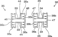
Fig. 2 is the summary cutaway view of the B-B line along Fig. 1.
Fig. 3 is the summary stereogram of the execution mode of the piezoelectric vibration piece that uses of the piezoelectric device in the presentation graphs 1.
Fig. 4 be along Fig. 3 C-C line analyse and observe end view drawing.
Fig. 5 is near the part figure of root of the shaker arm of piezoelectric vibration piece of the present invention.
Fig. 6 is the variation of embodiments of the present invention, is with near the partial enlarged drawing after amplifying the root of the shaker arm of piezoelectric vibration piece.
Fig. 7 is the summary vertical view of an example of the piezoelectric vibration piece of representing that piezoelectric device in the past uses.
Fig. 8 is the summary cutaway view of the A-A line along Fig. 7.
Fig. 9 is with near the partial enlarged drawing after amplifying the root of in the past shaker arm.
Embodiment
Fig. 1~Fig. 4 represents the execution mode of piezoelectric device of the present invention, Fig. 1 is its summary vertical view, Fig. 2 is the summary cutaway view of the B-B line along Fig. 1, Fig. 3 is the summary stereogram of the execution mode of the piezoelectric vibration piece that uses of the piezoelectric device in the presentation graphs 1, Fig. 4 be along Fig. 3 C-C line analyse and observe end view drawing.
In addition, in Fig. 1 and Fig. 2,, omit diagram exciting electrode described later for the ease of understanding.And the parallel oblique line among Fig. 3 is not the expression section, and the expression electrode.
In these figure, piezoelectric device 30 expressions constitute the example of piezoelectric vibrator, and this piezoelectric device 30 is being accommodated piezoelectric vibration piece 32 as depicted in figs. 1 and 2 in encapsulation 37.Encapsulation forms by stacked the 1st substrate 55 and the 2nd substrate 56 37 as shown in Figure 2, for example will be shaped as the ceramic green sheet (green sheet) of the aluminum oxide of insulating material, form illustrated shape after sintering form.
And encapsulation 37 is used seal member 38 to engage the lid 40 of clear glass system, thereby is hermetic sealed after having accommodated piezoelectric vibration piece 32.Thus, behind sealing lid 40, repair the electrode of piezoelectric vibration piece 32 etc. from external irradiation laser LB, thus can regulating frequency.
In addition, the tuning fork-like profile of this piezoelectric vibration piece 32 and be located at elongated slot on each shaker arm described later for example can be utilized material such as Wet-type etching such as fluorspar acid solution or dry-etching quartz wafer respectively and forms.
That is, be provided with at the two ends of the Width of this base portion 51 and be a plurality of extraction electrodes 52,53 heteropole, that be connected with mounting terminal 41,42 (with reference to Fig. 2) each other.This extraction electrode the 52, the 53rd is used for driving the electrode of using voltage to exciting electrode transmission described later, for example forms by sputter chromium (Cr) and gold (Au).
And, as shown in Figure 3 and Figure 4, on shaker arm 35,36, utilize to be configured in the inner face electrode 44,45 of elongated slot 33,34 inner faces and to be configured in side electrode 46,47 with this inner face electrode 44,45 opposed side 35b, 36b, become the exciting electrode of driving electrode.That is, inner face electrode 44 and side electrode 46 be configuration opposed to each other mutually, and inner face electrode 45 and side electrode 47 also dispose mutually opposed to each other, and is connected with extraction electrode 52,53 on the base portion 51, so that inner face electrode 44,45 and side electrode 46,47 are heteropole each other.These exciting electrodes for example form by sputter chromium (Cr) and gold (Au).
Thus, in the time of on piezoelectric device 30 being installed in installation base plate etc., pass to each exciting electrode of shaker arm 35,36 by extraction electrode 52,53 from each mounting terminal 41,42 from the driving voltage of outside.And this moment,, can improve the electrical efficiency of the intra-zone that is formed with exciting electrode in each shaker arm 33,34 when driving by applying driving voltage to inner face electrode 44,45 and side electrode opposed 46,47 with it.
And preferably, inner face electrode 44,45 and side electrode 46,47 describedly are connected with extraction electrode 52,53 according to following, and become heteropole each other.
At first, extraction electrode 53 is connected with the inner face electrode 44 of elongated slot 33 by the interarea (positive and negative) of base portion 51, and is connected with the side electrode 47 with on the inner face electrode 45 opposed side 36b that is located at shaker arm 36.
On the other hand, extraction electrode 52 is behind the side 35b and front end of shaker arm 35, the inner face electrode 44 that connects shaker arm 35, so as not with extraction electrode 53 and the interarea electrode, inner face electrode 44, side electrode 47 contacts that are connected the base portion 51 of this extraction electrode 53.
That is, extraction electrode 52 connects the side electrode 46 on the side 35b of shaker arms 35, and the connection of this side electrode 46 by the interarea (positive and negative) of base portion 51 be with electrode 48, is connected with inner face electrode 44 in the elongated slot 33 of shaker arm 35.
In addition, when electrode 48 was used in the connection that makes side electrode 46 connect base portion 51, side electrode 46 was not covered by the 51a of thigh portion between shaker arm 35 and shaker arm 36 of base portion 51, and does not produce electric field in the 51a of thigh portion.
Herein, the width dimensions Wa of each shaker arm 35,36 of the piezoelectric vibration piece 32 of present embodiment has the widening portion of widening towards base portion 51 sides 60,60 at the position with respect to the root of base portion 51 of shaker arm 35,36.
This widening portion 60,60 preferably, form as shown in Figure 1, when overlooking, be roughly symmetry of the outside widening portion 60a at center and inboard (51a of thigh portion side) widening portion 60b with dummy line CL along the length direction at the center of the Width by shaker arm 35,36.Thus, obtain the inboard of shaker arm 35,36 and the balance in the outside, can realize stable flexural vibrations.
Specifically, widening portion 60 is when overlooking (level is looked), and the width dimensions of root part is along with tilting in the hope of not changing the enlarged degree of width towards base portion 51 sides from front, and as shown in Figure 3, its side 60c forms the inclined plane with homogeneous angular.
And the Breadth Maximum Wb of the position of the contact base portion 51 of widening portion 60 is big more, easy more as hereinafter described carry out electrode around, it is widened at least than by the big width of width of the sidewall 35a that elongated slot 33 forms is set.But, if the Breadth Maximum Wb of this widening portion 60 is excessive, then the 51a of thigh portion disappears, widening portion 60 self becomes the part of the effect of the similar thigh of performance portion, perhaps for fear of the thigh portionization of this widening portion 60, though can increase strand width dimensions of the 51a of portion, will cause the integral width of piezoelectric vibration piece 32 to become big like this.Therefore, widening portion 60 forms and makes Breadth Maximum Wb be about 23 μ m, to keep the thigh 51a of portion.And the length L 1 of widening portion 60 forms about the 50 μ m of roughly twice of Breadth Maximum Wb.
And side electrode 46,47 is around to side 60c, 60c, 60c, the 60c of this widening portion 60,60,60,60.In addition, side electrode 46 also is around to interarea (positive and negative) 60d of the widening portion 60b of shaker arm 35 inboards in these a plurality of widening portions.
Promptly, as described above, do not contact with the exciting electrode of its electrical connection in order to make side's extraction electrode 52 and to reach with the opposing party's extraction electrode 53 with the exciting electrode of its electrical connection, make side and the front end of side's extraction electrode 52 around shaker arm 35, to form side electrode 46, this side electrode 46 is around on the interarea of base portion 51, on base portion 51, forms the connection electrode 48 that is connected with the inner face electrode 45 of shaker arm 36.Therefore, in the time of on the connection usefulness electrode 48 that this side electrode 46 is around on the base portion 51, use side 60c and the interarea 60d of widening portion 60b.
Embodiments of the present invention are by the above formation, and piezoelectric vibration piece 32 has widening portion 60,60, and it makes the width dimensions Wa of each shaker arm 35,36 widen towards base portion 51 sides at the position with respect to the root of base portion 51 of shaker arm 35,36.Therefore, when shaker arm 35,36 flexural vibrations, maximum stress works, and can improve the rigidity of the big root portion of distortion change.Thus, the flexural vibrations of shaker arm 35,36 are stable, are suppressed towards the vibration component of unwanted direction (for example thickness direction of shaker arm), so can suppress the CI value lowlyer.
In addition, side electrode 46 is around to the side 60c and the interarea 60d of widening portion 60.Therefore, for example promptly shown in Figure 5 as near the part figure the root of shaker arm 35, when interarea (positive and negative) electrode of the sidewall 35a that can not accurately form shaker arm 35, in the time of perhaps can not forming the interarea electrode of sidewall 35a fully etc., even the interarea electrode of the sidewall 35a of shaker arm 35 and being connected with electrode 48 of base portion 51 do not contact, side 60c that also can be by being around to widening portion 60 and the electrode of interarea 60d, be electrically connected being connected on side electrode 46 and the base portion 51, can avoid broken string with electrode 48.
And, needn't consider the interarea electrode of the sidewall 35a of shaker arm 35, can connect being connected on side electrode 46 and the base portion 51 with electrode 48, so can make the interarea electrode width of the sidewall 35a of shaker arm 35 form lessly or also can not form, therefore can prevent to contact with inner face electrode 44 in the elongated slot 33.
Fig. 6 is the variation of embodiments of the present invention, is with near the partial enlarged drawing after amplifying the root of the shaker arm of piezoelectric vibration piece.
In the figure, the part of having given the symbol identical with the piezoelectric vibration piece 32 of Fig. 1~Fig. 5 is identical structure, thus omit repeat specification, below main explanation difference.
In Fig. 6, piezoelectric vibration piece 70 only is that with the difference of the piezoelectric vibration piece 32 of Fig. 1~Fig. 5 the shape of widening portion 60 is different.
That is, the widening portion 60,60,60,60 of the piezoelectric vibration piece 70 of Fig. 6 changes the degree of widening by stages towards base portion 51 sides and widens.That is, each widening portion 60 forms when overlooking, and has the variation point P that changes the angle of inclination therein on the way.
More preferably, each widening portion 60 forms the widening portion 60-1 of the degree of widening of the widening portion 60-2 that makes its base portion side greater than front.Thus, bigger stress works, and can improve the rigidity of the root portion of the big base portion side of distortion change.
In addition, in the variation of Fig. 6, the degree of widening of each widening portion 60 only changes a stage, is formed by the widening portion 60-1,60-2 that has two different angles of inclination when overlooking, but the degree of widening can certainly be according to two stages or more than two phasic changes.
The variation of embodiments of the present invention is by the above formation, widening portion 60 changes the degree of widening by stages towards base portion 51 sides and widens, so compare when widening degree with not changing, can prolong the length that the interarea 60d of the side 60c of widening portion 60 and widening portion 60 contacts.Therefore, compare, can prevent the broken string of the interarea 60d of the side 60c of widening portion 60 and widening portion 60 with the piezoelectric vibration piece 32 of Fig. 1~Fig. 5.
The invention is not restricted to above-mentioned execution mode.Each component part of execution mode can suitably make up or omit, or with not shown other component parts combinations.
For example, certainly piezoelectric vibration piece shown in Figure 6 70 is housed in the encapsulation illustrated in figures 1 and 2 37, forming piezoelectric device, and encapsulation is not limited to the encapsulation of case shape, for example also can be cylindrical container etc.
In addition, about piezoelectric vibration piece, in Fig. 1~Fig. 6, base portion 51 is bonded in the encapsulation 37, but the invention is not restricted to this, for example, also can with shaker arm 35,36 dividually, extend the 2nd arm from the end of base portion 51, the 2nd arm is bonded in the encapsulation.
Claims (3)
1. piezoelectric vibration piece is characterized in that having:
Base portion, it is formed by piezoelectric;
A plurality of shaker arms, itself and described base portion form as one, and extend in parallel to each other;
Elongated slot, it alongst forms in the interarea of described each shaker arm;
Exciting electrode, it is formed by inner face electrode that is configured in described elongated slot inner face and the side electrode with the opposed side of described inner face electrode that is configured in the described shaker arm at described inner face electrode place,
Described piezoelectric vibration piece has widening portion, and it makes the width dimensions of described each shaker arm widen towards base portion side at the position with respect to the root of described base portion of described shaker arm, and described side electrode is around on the side and interarea of this widening portion.
2. piezoelectric vibration piece according to claim 1 is characterized in that, described widening portion changes the degree of widening by stages towards base portion side and widens.
3. in encapsulation or housing, accommodated the piezoelectric device of piezoelectric vibration piece for one kind, it is characterized in that described piezoelectric vibration piece has:
Base portion, it is formed by piezoelectric;
A plurality of shaker arms, itself and described base portion form as one, and extend in parallel to each other;
Elongated slot, it alongst forms in the interarea of described each shaker arm;
Exciting electrode, it is formed by inner face electrode that is configured in described elongated slot inner face and the side electrode with the opposed side of described inner face electrode that is configured in the described shaker arm at described inner face electrode place,
Described piezoelectric vibration piece has widening portion, and it makes the width dimensions of described each shaker arm widen towards base portion side at the position with respect to the root of described base portion of described shaker arm, and described side electrode is around on the side and interarea of this widening portion.
Applications Claiming Priority (2)
| Application Number | Priority Date | Filing Date | Title |
|---|---|---|---|
| JP2005081501A JP4277818B2 (en) | 2005-03-22 | 2005-03-22 | Piezoelectric vibrating piece and piezoelectric device |
| JP2005081501 | 2005-03-22 |
Publications (2)
| Publication Number | Publication Date |
|---|---|
| CN1838533A CN1838533A (en) | 2006-09-27 |
| CN100508383C true CN100508383C (en) | 2009-07-01 |
Family
ID=37015818
Family Applications (1)
| Application Number | Title | Priority Date | Filing Date |
|---|---|---|---|
| CNB2006100652903A Active CN100508383C (en) | 2005-03-22 | 2006-03-21 | Piezoelectric vibration piece and piezoelectric device |
Country Status (3)
| Country | Link |
|---|---|
| US (4) | US7659798B2 (en) |
| JP (1) | JP4277818B2 (en) |
| CN (1) | CN100508383C (en) |
Families Citing this family (25)
| Publication number | Priority date | Publication date | Assignee | Title |
|---|---|---|---|---|
| JP4409979B2 (en) * | 2004-02-10 | 2010-02-03 | シチズンホールディングス株式会社 | Vibrator |
| TW200633377A (en) * | 2005-02-02 | 2006-09-16 | Nihon Dempa Kogyo Co | Piezo-electric vibrator |
| JP4277818B2 (en) * | 2005-03-22 | 2009-06-10 | セイコーエプソン株式会社 | Piezoelectric vibrating piece and piezoelectric device |
| JP4694380B2 (en) * | 2006-02-06 | 2011-06-08 | 株式会社日立製作所 | Thin film tuning fork type bending vibrator and electric signal processing element |
| JP2010060361A (en) * | 2008-09-02 | 2010-03-18 | Murata Mfg Co Ltd | Tuning fork-type vibrator, manufacturing method of tuning fork-type vibrator, and angular velocity sensor |
| JP4879963B2 (en) * | 2008-12-25 | 2012-02-22 | 日本電波工業株式会社 | Piezoelectric vibrating piece, piezoelectric vibrator and piezoelectric oscillator |
| JP5369741B2 (en) * | 2009-02-12 | 2013-12-18 | セイコーエプソン株式会社 | Vibrating piece and vibrator |
| JP2010252302A (en) * | 2009-03-25 | 2010-11-04 | Seiko Epson Corp | Bending vibrator piece and oscillator using the same |
| JP2010233339A (en) * | 2009-03-26 | 2010-10-14 | Seiko Epson Corp | Piezoelectric motor, liquid jetting device and timepiece |
| JP5385037B2 (en) * | 2009-07-21 | 2014-01-08 | エスアイアイ・クリスタルテクノロジー株式会社 | Piezoelectric vibrating piece, piezoelectric vibrator, oscillator, electronic device, radio timepiece, and method of manufacturing piezoelectric vibrating piece |
| JP5482541B2 (en) * | 2009-10-01 | 2014-05-07 | セイコーエプソン株式会社 | Vibrating piece, vibrator, oscillator, and electronic device |
| US8299863B2 (en) * | 2009-12-25 | 2012-10-30 | Seiko Epson Corporation | Flexural mode resonator element, resonating device, and electronic apparatus |
| US8304968B2 (en) * | 2010-03-17 | 2012-11-06 | Seiko Epson Corporation | Vibrator element, vibrator, oscillator, and electronic apparatus |
| US20110227458A1 (en) * | 2010-03-17 | 2011-09-22 | Seiko Epson Corporation | Piezoelectric resonator element, piezoelectric device, and electronic apparatus |
| JP5499852B2 (en) | 2010-04-08 | 2014-05-21 | セイコーエプソン株式会社 | Vibrating piece, vibrator |
| JP2012039509A (en) * | 2010-08-10 | 2012-02-23 | Seiko Instruments Inc | Piezoelectric vibrating piece, piezoelectric resonator, oscillator, electronic device, and radio-controlled timepiece |
| US8963402B2 (en) * | 2010-11-30 | 2015-02-24 | Seiko Epson Corporation | Piezoelectric vibrator element, piezoelectric module, and electronic device |
| JP5685962B2 (en) * | 2011-02-02 | 2015-03-18 | セイコーエプソン株式会社 | Vibrating piece, vibrator, oscillator and electronic device |
| JP5838749B2 (en) * | 2011-11-16 | 2016-01-06 | セイコーエプソン株式会社 | Vibrator, vibrating device and electronic equipment |
| JP2013197994A (en) * | 2012-03-21 | 2013-09-30 | Seiko Instruments Inc | Piezoelectric vibration piece, piezoelectric vibrator, oscillator, electronic apparatus, and wave clock |
| JP5696751B2 (en) * | 2013-08-29 | 2015-04-08 | セイコーエプソン株式会社 | Vibrating piece and vibrator |
| JP6676403B2 (en) | 2016-02-23 | 2020-04-08 | エスアイアイ・クリスタルテクノロジー株式会社 | Piezoelectric vibrating reed and piezoelectric vibrator |
| CN109075766B (en) * | 2016-05-25 | 2022-04-19 | 株式会社村田制作所 | Resonator and resonance device |
| JP6927768B2 (en) * | 2017-06-30 | 2021-09-01 | 京セラ株式会社 | Crystal device |
| US10924866B2 (en) * | 2019-02-27 | 2021-02-16 | Nokia Technologies Oy | Piezoelectric speaker |
Family Cites Families (10)
| Publication number | Priority date | Publication date | Assignee | Title |
|---|---|---|---|---|
| JP3858575B2 (en) | 2000-09-01 | 2006-12-13 | セイコーエプソン株式会社 | Vibrating piece, vibrator, oscillator and mobile phone device |
| EP1788702A3 (en) * | 2000-12-25 | 2008-01-16 | Seiko Epson Corporation | Vibrating piece, vibrator, oscillator, and electronic equipment |
| JP3812724B2 (en) * | 2001-09-13 | 2006-08-23 | セイコーエプソン株式会社 | Vibrating piece, vibrator, oscillator and electronic device |
| JP4026074B2 (en) * | 2003-06-30 | 2007-12-26 | 有限会社ピエデック技術研究所 | Crystal unit, crystal unit and crystal oscillator |
| JP4329492B2 (en) * | 2003-10-28 | 2009-09-09 | セイコーエプソン株式会社 | Piezoelectric vibrating piece, piezoelectric device, manufacturing method thereof, mobile phone device using the piezoelectric device, and electronic equipment using the piezoelectric device |
| JP4409979B2 (en) * | 2004-02-10 | 2010-02-03 | シチズンホールディングス株式会社 | Vibrator |
| DE602004027033D1 (en) * | 2004-09-03 | 2010-06-17 | Eta Sa Mft Horlogere Suisse | Quartz resonator with very small dimensions |
| US7368861B2 (en) * | 2004-09-24 | 2008-05-06 | Seiko Epson Corporation | Piezoelectric resonator element and piezoelectric device |
| JP4301200B2 (en) * | 2004-10-20 | 2009-07-22 | セイコーエプソン株式会社 | Piezoelectric vibrating piece and piezoelectric device |
| JP4277818B2 (en) * | 2005-03-22 | 2009-06-10 | セイコーエプソン株式会社 | Piezoelectric vibrating piece and piezoelectric device |
-
2005
- 2005-03-22 JP JP2005081501A patent/JP4277818B2/en active Active
-
2006
- 2006-03-21 CN CNB2006100652903A patent/CN100508383C/en active Active
- 2006-03-22 US US11/387,101 patent/US7659798B2/en active Active
-
2009
- 2009-12-21 US US12/643,290 patent/US7999637B2/en active Active
-
2011
- 2011-07-07 US US13/178,197 patent/US8405474B2/en active Active
-
2013
- 2013-02-26 US US13/777,359 patent/US8633788B2/en active Active
Also Published As
| Publication number | Publication date |
|---|---|
| US20130169115A1 (en) | 2013-07-04 |
| US20110260587A1 (en) | 2011-10-27 |
| US8405474B2 (en) | 2013-03-26 |
| CN1838533A (en) | 2006-09-27 |
| US8633788B2 (en) | 2014-01-21 |
| US20100096955A1 (en) | 2010-04-22 |
| US7999637B2 (en) | 2011-08-16 |
| US20060214749A1 (en) | 2006-09-28 |
| JP4277818B2 (en) | 2009-06-10 |
| US7659798B2 (en) | 2010-02-09 |
| JP2006270177A (en) | 2006-10-05 |
Similar Documents
| Publication | Publication Date | Title |
|---|---|---|
| CN100508383C (en) | Piezoelectric vibration piece and piezoelectric device | |
| EP1478090B1 (en) | Tuning-fork-type piezoelectric resonator element | |
| US7015630B2 (en) | Piezoelectric vibration piece, piezoelectric device using piezoelectric vibration piece, portable phone unit using piezoelectric device, and electronic equipment using piezoelectric device | |
| US9837982B2 (en) | Vibrating element, vibrator, oscillator, and electronic device with stepped excitation section | |
| JP4211578B2 (en) | Piezoelectric vibrating piece, manufacturing method thereof, piezoelectric device, mobile phone device using piezoelectric device, and electronic apparatus using piezoelectric device | |
| CN102111120B (en) | Bending vibration pieces, vibration device, and electronic apparatus | |
| JP4207873B2 (en) | Piezoelectric vibrating piece and piezoelectric device | |
| JP5652122B2 (en) | Vibrating piece, vibrating device and electronic device | |
| JP4360214B2 (en) | Piezoelectric vibration device | |
| US20060012269A1 (en) | Quartz crystal unit and holding structure for same | |
| JP2011199331A (en) | Vibration piece, vibrator, and oscillator | |
| JP2008211773A (en) | Tuning fork type piezoelectric vibrator | |
| JP2005167992A (en) | Tuning fork-type crystal vibrator | |
| JP4508204B2 (en) | Tuning fork type piezoelectric vibrator | |
| JP4900489B2 (en) | Tuning fork type piezoelectric vibrator | |
| JP2014112959A (en) | Vibration piece, vibrator, and oscillator | |
| JP4222288B2 (en) | Piezoelectric vibrating piece and piezoelectric device | |
| JP4020031B2 (en) | Piezoelectric vibrating piece, piezoelectric device using the piezoelectric vibrating piece, mobile phone device using the piezoelectric device, and electronic equipment using the piezoelectric device | |
| JP2006203763A (en) | Piezoelectric vibrating piece, method for adjusting characteristic thereof and piezoelectric device | |
| JP2007251727A (en) | Piezoelectric oscillator | |
| JP2003133893A (en) | Quartz vibrator structure | |
| JP2006339692A (en) | Piezoelectric vibrator | |
| JP2016134801A (en) | Piezoelectric vibration piece and piezoelectric vibrator |
Legal Events
| Date | Code | Title | Description |
|---|---|---|---|
| C06 | Publication | ||
| PB01 | Publication | ||
| C10 | Entry into substantive examination | ||
| SE01 | Entry into force of request for substantive examination | ||
| C14 | Grant of patent or utility model | ||
| GR01 | Patent grant |