CN100501503C - Image stabilizer, lens apparatus and imager apparatus - Google Patents
Image stabilizer, lens apparatus and imager apparatus Download PDFInfo
- Publication number
- CN100501503C CN100501503C CNB200610093469XA CN200610093469A CN100501503C CN 100501503 C CN100501503 C CN 100501503C CN B200610093469X A CNB200610093469X A CN B200610093469XA CN 200610093469 A CN200610093469 A CN 200610093469A CN 100501503 C CN100501503 C CN 100501503C
- Authority
- CN
- China
- Prior art keywords
- lens
- magnet
- coil
- fixed
- optical axis
- Prior art date
- Legal status (The legal status is an assumption and is not a legal conclusion. Google has not performed a legal analysis and makes no representation as to the accuracy of the status listed.)
- Expired - Fee Related
Links
Images


Classifications
-
- H—ELECTRICITY
- H04—ELECTRIC COMMUNICATION TECHNIQUE
- H04N—PICTORIAL COMMUNICATION, e.g. TELEVISION
- H04N23/00—Cameras or camera modules comprising electronic image sensors; Control thereof
- H04N23/60—Control of cameras or camera modules
- H04N23/68—Control of cameras or camera modules for stable pick-up of the scene, e.g. compensating for camera body vibrations
-
- G—PHYSICS
- G02—OPTICS
- G02B—OPTICAL ELEMENTS, SYSTEMS OR APPARATUS
- G02B7/00—Mountings, adjusting means, or light-tight connections, for optical elements
- G02B7/02—Mountings, adjusting means, or light-tight connections, for optical elements for lenses
- G02B7/04—Mountings, adjusting means, or light-tight connections, for optical elements for lenses with mechanism for focusing or varying magnification
-
- G—PHYSICS
- G03—PHOTOGRAPHY; CINEMATOGRAPHY; ANALOGOUS TECHNIQUES USING WAVES OTHER THAN OPTICAL WAVES; ELECTROGRAPHY; HOLOGRAPHY
- G03B—APPARATUS OR ARRANGEMENTS FOR TAKING PHOTOGRAPHS OR FOR PROJECTING OR VIEWING THEM; APPARATUS OR ARRANGEMENTS EMPLOYING ANALOGOUS TECHNIQUES USING WAVES OTHER THAN OPTICAL WAVES; ACCESSORIES THEREFOR
- G03B5/00—Adjustment of optical system relative to image or object surface other than for focusing
- G03B5/06—Swinging lens about normal to the optical axis
-
- H—ELECTRICITY
- H04—ELECTRIC COMMUNICATION TECHNIQUE
- H04N—PICTORIAL COMMUNICATION, e.g. TELEVISION
- H04N23/00—Cameras or camera modules comprising electronic image sensors; Control thereof
- H04N23/60—Control of cameras or camera modules
- H04N23/68—Control of cameras or camera modules for stable pick-up of the scene, e.g. compensating for camera body vibrations
- H04N23/681—Motion detection
- H04N23/6812—Motion detection based on additional sensors, e.g. acceleration sensors
-
- H—ELECTRICITY
- H04—ELECTRIC COMMUNICATION TECHNIQUE
- H04N—PICTORIAL COMMUNICATION, e.g. TELEVISION
- H04N23/00—Cameras or camera modules comprising electronic image sensors; Control thereof
- H04N23/60—Control of cameras or camera modules
- H04N23/68—Control of cameras or camera modules for stable pick-up of the scene, e.g. compensating for camera body vibrations
- H04N23/682—Vibration or motion blur correction
- H04N23/685—Vibration or motion blur correction performed by mechanical compensation
- H04N23/687—Vibration or motion blur correction performed by mechanical compensation by shifting the lens or sensor position
Landscapes
- Engineering & Computer Science (AREA)
- Multimedia (AREA)
- Signal Processing (AREA)
- Physics & Mathematics (AREA)
- General Physics & Mathematics (AREA)
- Optics & Photonics (AREA)
- Adjustment Of Camera Lenses (AREA)
- Measurement Of Length, Angles, Or The Like Using Electric Or Magnetic Means (AREA)
- Studio Devices (AREA)
Abstract
一种能够稳定模糊图像的图像稳定器。该图像稳定器包括第一和第二霍尔元件以及其上固定有磁铁的轭,该轭包括一凸出部分以从该磁铁的该边缘部分释放磁通量。在将磁铁和线圈支撑固定器之一固定到移动框并且校正透镜的光轴与透镜系统的光轴匹配的状态下,该第一和第二霍尔元件朝向该第一和第二方向移动,使得该第一和第二霍尔元件适当地定位在由该两霍尔元件从该磁铁接收的磁力成为基准值的位置,然后,将磁铁和线圈支撑元件中的另一个固定到支撑框。
An image stabilizer that stabilizes blurry images. The image stabilizer includes first and second hall elements and a yoke on which a magnet is fixed, the yoke including a protruding portion to release magnetic flux from the edge portion of the magnet. In a state where one of the magnet and the coil support fixture is fixed to the moving frame and the optical axis of the correction lens matches the optical axis of the lens system, the first and second Hall elements move toward the first and second directions, The first and second Hall elements are properly positioned at a position where the magnetic force received by the two Hall elements from the magnet becomes a reference value, and then, the other of the magnet and the coil support member is fixed to the supporting frame.
Description
技术领域 technical field
本发明涉及一种图像稳定器、包括这种图像稳定器的透镜装置以及包括这种透镜装置的成像器装置,该图像稳定器通过在垂直于透镜系统的光轴的方向上移动校正透镜,从而使得该校正透镜的光轴与该透镜系统的光轴相匹配,以稳定在拍摄时由于运动和振动而产生的模糊图像。The present invention relates to an image stabilizer, a lens device including such an image stabilizer, and an imager device including such a lens device, the image stabilizer moves a correction lens in a direction perpendicular to the optical axis of the lens system, thereby The optical axis of the correcting lens is matched with the optical axis of the lens system to stabilize blurred images caused by motion and vibration during shooting.
背景技术 Background technique
近年来,诸如数字照相机和摄影机的成像器装置的性能已经得到了显著的提高,其使得对于任何人容易地以高图像质量和高效率拍摄静态图片和移动图片成为可能。这种成像器的提高效率归功于透镜、CCD(电荷耦合装置),也就是固体图像拾取装置和图像处理电路的高性能。In recent years, the performance of imager devices such as digital still cameras and video cameras has been significantly improved, which makes it possible for anyone to easily take still pictures and moving pictures with high image quality and high efficiency. The improved efficiency of this imager is attributed to the high performance of the lens, CCD (Charge Coupled Device), which is a solid-state image pickup device, and image processing circuits.
然而,尽管能够将透镜、CCD等的性能制造得更高,但是如果在摄影师持有照相机(成像器装置)的手中发生手的颤动,那么在高分辨率图像中会产生模糊,并且所拍摄的图像不可避免地模糊了。为了解决这一问题,一部分相对昂贵的照相机装备有能够对由于在拍摄时的照相机振动等产生模糊的图像进行校正的图像稳定器。然而,需要这种图像稳定器的照相机并不是专业水平的照相机,并且应当理解,对于针对大量具有较少摄影经验的摄影爱好者的消费者照相机来说,图像稳定器是必不可少的。However, although the performance of the lens, CCD, etc. can be made higher, if a hand shake occurs in the photographer's hand holding the camera (imager device), blurring occurs in the high-resolution image, and the captured The image is inevitably blurred. In order to solve this problem, some relatively expensive cameras are equipped with image stabilizers capable of correcting blurred images due to camera vibration or the like at the time of shooting. However, cameras requiring such an image stabilizer are not professional level cameras, and it will be understood that image stabilizers are essential for consumer cameras aimed at a large number of amateur photographers with less photographic experience.
通常,对于较小和较轻的照相机(成像器装置)的需要是强烈的,并且大部分摄影师喜欢重量轻且便于携带的照相机。然而,由于基于现有技术的图像稳定器相对尺寸较大,当这种巨大的图像稳定器安装在相机主体上时,整个照相机的尺寸将不可避免地变大,这与使照相机尺寸更小和重量更轻的要求是相矛盾的。另外,基于现有技术的图像稳定器需要大量部件,造成了照相机成本随着部件数量的增加而增大的问题。In general, the need for smaller and lighter cameras (imager devices) is strong, and most photographers prefer cameras that are lightweight and portable. However, since the image stabilizer based on the prior art is relatively large in size, when such a huge image stabilizer is mounted on the camera body, the size of the entire camera will inevitably become larger, which is different from making the camera smaller and The demands for lighter weight are contradictory. In addition, the image stabilizer based on the prior art requires a large number of parts, causing a problem that the cost of the camera increases as the number of parts increases.
例如,引用的专利参考文献1描述了基于现有技术的这种类型的图像稳定器。该引用的专利参考文献1描述了一种用于诸如摄录机和使用图像稳定器的透镜的透镜筒的光学装置的图像稳定器。描述于该引用的专利参考文献1(以下称作“第一现有技术实例”)中的图像稳定器具有如下特性。在通过使拍摄透镜的一部分在垂直平面内相对于光轴运动而能够校正模糊图像的图像稳定器中,该图像稳定器包括用于固定该校正透镜的透镜固定框,用于在该垂直平面内相对于光轴导引该透镜固定框朝向第一方向运动的第一导引机构,以及用于导引该透镜固定框朝向垂直于第一方向的第二方向运动的第二导引机构。该图像稳定器进一步包括用于朝向第一方向驱动该透镜固定框的第一驱动器,用于朝向第二方向驱动该透镜固定框的第二驱动器以及用于检测该校正透镜位置的位置检测器。当从该光轴观察时,该第一导引机构和该第二驱动器的一部分或该第二导引机构和该第一驱动器的一部分位于它们彼此重叠的位置。For example, the cited
基于具有在该引用的专利参考文献1中描述的上述设置的该图像稳定器,当从光轴方向观察行距移位器(pitch shifter)和偏转驱动器(yaw driver)或偏转移位器(yaw shifter)和行距驱动器(pitch driver)时,由于用来使该校正透镜运动的导引轴和用于驱动该导引轴的线圈或磁铁位于它们彼此重叠重叠的位置,因此可以预料到诸如减小图像稳定器的宽度和高度的影响。Based on the image stabilizer having the above-mentioned arrangement described in the cited
例如,引用的专利参考文献2描述了基于现有技术的图像稳定器的第二实例。该引用的专利参考文件2描述了一种用于诸如摄录机和使用图像稳定器的透镜的透镜筒的光学装置的图像稳定器。描述于该引用的专利参考文献2(以下称作“第二现有技术实例”)中的该图像稳定器具有如下特性。在通过使拍摄透镜的一部分在垂直平面内相对于光轴运动而能够校正模糊图像的图像稳定器中,该图像稳定器包括用于固定该校正透镜的透镜固定框。该校正透镜包括用于限定校正透镜的运动范围的第一限定部分,用于在该垂直平面内导引该透镜固定框相对于该光轴朝向该第一方向运动的第一导引机构,以及用于导引该透镜固定框朝向垂直于该第一方向的该第二方向运动的第二导引机构。该图像稳定器进一步包括用于朝向该第一方向驱动该透镜固定框的第一驱动器,用于朝向该第二方向驱动该透镜固定框的第二驱动器,用于检测该校正透镜的位置的位置检测器以及具有与该第一限定部分啮合以限定校正透镜的运动范围的第二限定部分的固定机构。该第一和第二限定部分位于该第一和第二驱动器的内侧上并几乎同心。For example, cited
基于具有在该引用的专利参考文献2中描述的上述设置的该图像稳定器,由于可动的限定元件位于校正透镜和驱动器之间的相对于光轴接近于一同心圆上,并且将要与该限定部分元件啮合的非啮合元件设置在固定框上以限定校正透镜的运动,因此能够将校正透镜的可运动范围限定在该可动部分内。于是,能够预料到诸如构造小的图像稳定器的效果。Based on the image stabilizer with the above arrangement described in the cited
同样,例如,引用的专利参考文献3描述了现有技术的图像稳定器的第三实例。该引用的专利参考文献3描述了安装在照相机等上的防振器,该防振器用于检测相对低频率的振动并将该检测到的振动作为避免模糊图像的信息来避免模糊图像。描述于引用的专利参考文献3(以下称作“第三现有技术实例”)中的防振器包括位于用于固定透镜组的透镜筒内并偏离该组透镜的光轴的校正光学机构,用于检测施加到该透镜筒的振动的振动检测器,以及用于根据来自该振动检测器的信号驱动该校正光学机构以隔离振动的防振控制器。该校正光学机构包括校正透镜,用于固定该校正透镜的固定框,用于以使该固定框能够沿与该组透镜的光轴方向不同的第一方向运动的方式固定该固定框的第一固定框,用于以使该第一固定框能够沿与该光轴方向和该第一方向不同的第二方向运动且固定到该透镜的透镜筒上的方式固定该第一固定框的第二固定框。该校正光学机构进一步包括用于使该第一和第二固定框沿该第一和第二方向运动的第一和第二线圈,由与该第一和第二线圈相对的第一和第二磁场产生元件构成的第一和第二驱动器,以及用于检测该固定框和该第一固定框沿该第一和第二方向运动的量的第一和第二位置检测器。至少一个该第一和第二磁场产生元件和该第一和第二位置检测器设置在固定到透镜的该透镜筒上并包含第二固定框的固定元件上。Also, for example, cited
基于具有描述于引用的专利参考文献3中的上述设置的防振器,可预料到的是该防振器能够响应直至高频振动的振动而不增加成本和大的空间。Based on the vibration isolator having the above arrangement described in cited
[引用的专利参考1]:日本公开专利申请No.2000-258813[Cited Patent Reference 1]: Japanese Laid-Open Patent Application No. 2000-258813
[引用的专利参考2]:日本公开专利申请No.2003-270695[Cited Patent Reference 2]: Japanese Laid-Open Patent Application No. 2003-270695
[引用的专利参考3]:日本公开专利申请No.3-186823[Cited Patent Reference 3]: Japanese Laid-Open Patent Application No. 3-186823
然而,当第一至第三现有技术的实例包括位置检测器以检测校正透镜的位置时,在上述任何一种情况下的位置检测器都是由发光装置和受光装置构成,该发光装置由发光二极管(LED)构成,该受光装置由位置敏感二极管(PSD)构成。在该第三现有技术的实例的情况下,发光装置结合到定子上,而受光装置结合到第二固定框上,并且基于该发光装置和受光装置可以检测该固定框在行距方向上相对于该第一固定框的位置。However, when the examples of the first to third prior arts include a position detector to detect the position of the correction lens, the position detector in any of the above cases is constituted by a light emitting device and a light receiving device, the light emitting device consisting of Light-emitting diodes (LEDs), and the light-receiving device consists of position-sensitive diodes (PSDs). In the case of the third prior art example, the light-emitting device is combined with the stator, and the light-receiving device is combined with the second fixed frame, and based on the light-emitting device and the light-receiving device, it can be detected that the fixed frame is relative to the fixed frame in the line distance direction. The position of the first fixed frame.
在这种情况下,该发光装置和该受光装置应当在其结合到该定子和该第二固定框后被正确地定位。由于发光装置和受光装置的中心部分不能可视地确认,因此难以使该发光装置和该受光装置正确地定位,并产生了在生产上所需要的工作效率不是太高的问题。同时,由于该位置探测器需要两种诸如LED和PSD的特殊电子装置,因此增加了部件的数量,这是不经济的。另外,产生了除了该位置检测外的整个装置的控制变得复杂的问题。In this case, the light emitting device and the light receiving device should be correctly positioned after they are coupled to the stator and the second fixing frame. Since the central portions of the light-emitting device and the light-receiving device cannot be visually confirmed, it is difficult to correctly position the light-emitting device and the light-receiving device, and there arises a problem that work efficiency required for production is not too high. Meanwhile, since the position detector requires two kinds of special electronic devices such as LED and PSD, the number of parts increases, which is uneconomical. In addition, there arises a problem that the control of the entire device other than the position detection becomes complicated.
发明内容 Contents of the invention
在基于现有技术的图像稳定器中,由于位置检测器由LED(发光二极管)和PSD(位置敏感二极管)构成,因此难以使该LED和该PSD正确地定位。同样,由于必须对该LED和该PSD进行控制,因此控制机构变得复杂并且生产过程上所需要的工作效率并不太高。In the image stabilizer based on the prior art, since the position detector is composed of an LED (Light Emitting Diode) and a PSD (Position Sensitive Diode), it is difficult to correctly position the LED and the PSD. Also, since the LED and the PSD must be controlled, the control mechanism becomes complicated and the work efficiency required in the production process is not too high.
基于本发明的一个方面,提供一种图像稳定器,其中校正透镜包括具有可相对移动的线圈和磁铁的驱动器并通过该驱动器固定到运动框,在该驱动器中,该线圈和磁铁中的一个固定到该运动框。另外,在本图像稳定器中,固定到可动地支撑该运动框的支撑框的另一个能够沿垂直于透镜系统光轴的第一方向和沿垂直于该第一方向的第二方向运动,该第二运动方向同样垂直于该光轴,对校正透镜的光轴进行控制,使得其与透镜系统的光轴一致。该图像稳定器进一步包括用于通过检测该磁铁的磁力来检测与该校正透镜的第一方向相关的位置信号的第一霍尔元件,用于通过检测该磁铁的磁力来检测与该校正透镜的第二方向相关的位置信号的第二霍尔元件,具有固定于其上的磁铁并具有从该磁铁的边缘部分释放出磁通量的凸出部分的轭。在本图像稳定器中,在磁铁和该线圈之一固定到该运动框的状态下,通过向第一和第二方向移动该第一和第二霍尔元件,将第一和第二霍尔元件定位于由该第一和第二霍尔元件接收的来自磁铁的磁力变为基准值的位置。另外,该磁铁和该线圈支撑元件中的另一个固定到支撑框并且其中使该校正透镜的光轴与该透镜系统的光轴相一致,并且其中该磁铁和该线圈支撑元件中的另一个固定到该支撑框。According to one aspect of the present invention, there is provided an image stabilizer, wherein the correction lens includes a driver having a relatively movable coil and a magnet and is fixed to the motion frame by the driver, and in the driver, one of the coil and the magnet is fixed to the motion box. In addition, in the present image stabilizer, the other of the supporting frame fixed to the movable frame that supports the moving frame is movable in a first direction perpendicular to the optical axis of the lens system and in a second direction perpendicular to the first direction, This second direction of movement is likewise perpendicular to the optical axis, the optical axis of the correction lens being controlled such that it coincides with the optical axis of the lens system. The image stabilizer further includes a first Hall element for detecting a position signal related to the first direction of the correction lens by detecting the magnetic force of the magnet, for detecting a position signal relative to the correction lens by detecting the magnetic force of the magnet. A second Hall element for a second direction-dependent position signal has a magnet fixed thereto and a yoke having a protruding portion releasing magnetic flux from an edge portion of the magnet. In the present image stabilizer, in a state where one of the magnet and the coil is fixed to the motion frame, by moving the first and second Hall elements in the first and second directions, the first and second Hall elements are moved to the first and second directions. The element is positioned at a position where the magnetic force from the magnet received by the first and second Hall elements becomes a reference value. In addition, the other of the magnet and the coil support member is fixed to the support frame and wherein the optical axis of the correction lens is aligned with the optical axis of the lens system, and wherein the other of the magnet and the coil support member is fixed to the support frame.
基于本发明的图像稳定器、透镜装置和成像器装置,由于将霍尔元件用作位置检测器,该驱动器的磁铁还能够用作用于为该霍尔元件提供必须信息的部件。结果,位置检测器所需要的部件数量降低,并且能够容易和可靠地执行校正模糊图像的控制。另外,由于该轭包括凸出部分,则与该霍尔元件相对的该轭的磁通量可主动地释放到该凸出部分,并且靠近该凸出部分的磁通密度沿平行于该磁铁等的边缘方向基本上保持均匀。于是,当运动框朝向第一方向运动时,第二霍尔元件的磁通密度的改变能够大大降低。同样,类似的当该运动框朝向该第二方向运动时,第一霍尔元件的磁通密度的改变能够大大地降低。结果,第一和第二霍尔元件之间的相互干扰能够大大降低,并且能够极其精确地对位置进行检测。Based on the image stabilizer, lens device and imager device of the present invention, since the Hall element is used as a position detector, the magnet of the driver can also be used as a part for providing the Hall element with necessary information. As a result, the number of parts required for the position detector is reduced, and control to correct blurred images can be easily and reliably performed. In addition, since the yoke includes a protruding portion, the magnetic flux of the yoke opposed to the Hall element can be actively released to the protruding portion, and the magnetic flux density near the protruding portion is along the edge parallel to the magnet or the like. The direction remains substantially uniform. Therefore, when the moving frame moves toward the first direction, the change of the magnetic flux density of the second Hall element can be greatly reduced. Similarly, when the moving frame moves toward the second direction, the change of the magnetic flux density of the first Hall element can be greatly reduced. As a result, mutual interference between the first and second Hall elements can be greatly reduced, and position detection can be performed extremely accurately.
通过简单的结构能够实现一种图像稳定器,包含该图像稳定器的透镜装置以及包含该透镜装置的成像器装置。基于该图像稳定器、透镜装置和成像器装置的这些结构,由于将霍尔元件用作位置检测器,固定该磁铁的轭包括凸出部分并且与该霍尔元件相对的该轭的磁通量能够主动地释放到该凸出部分,因此靠近该凸出部分的磁通密度沿平行于该磁铁等的边缘的方向能够基本上保持均匀。于是,当该运动框朝向该第一方向运动时,第二霍尔元件的磁通密度的改变能够大大降低。同样,类似的当该运动框朝向该第二方向运动时,第一霍尔元件的磁通密度的改变能够大大地降低。结果,第一和第二霍尔元件之间的相互干扰能够大大降低,并且能够非常精确地对位置进行检测。An image stabilizer, a lens device including the image stabilizer, and an imager device including the lens device can be realized with a simple structure. Based on these structures of the image stabilizer, lens device, and imager device, since the Hall element is used as a position detector, the yoke fixing the magnet includes a convex portion and the magnetic flux of the yoke opposing the Hall element can actively is released to the protruding portion, and therefore the magnetic flux density near the protruding portion can be kept substantially uniform in a direction parallel to the edge of the magnet or the like. Therefore, when the moving frame moves toward the first direction, the change of the magnetic flux density of the second Hall element can be greatly reduced. Similarly, when the moving frame moves toward the second direction, the change of the magnetic flux density of the first Hall element can be greatly reduced. As a result, mutual interference between the first and second Hall elements can be greatly reduced, and the position can be detected very accurately.
附图说明 Description of drawings
图1是从前侧示出基于本发明第一实施例的透镜装置的透视图;1 is a perspective view showing a lens device based on a first embodiment of the present invention from the front side;
图2是从后侧示出的示于图1中的透镜装置的透视图;Figure 2 is a perspective view of the lens arrangement shown in Figure 1, shown from the rear side;
图3是示于图1中的透镜装置的前视图;Figure 3 is a front view of the lens device shown in Figure 1;
图4是示于图1中的透镜装置的后视图;Figure 4 is a rear view of the lens device shown in Figure 1;
图5是示于图1中的透镜装置的左手侧正视图;Figure 5 is a left-hand front view of the lens arrangement shown in Figure 1;
图6是示于图1中的透镜装置的右手侧正视图;Figure 6 is a right-hand front view of the lens arrangement shown in Figure 1;
图7是示于图1中的透镜装置的平面图;Fig. 7 is a plan view of the lens device shown in Fig. 1;
图8是示于图1的透镜装置的仰视图;Fig. 8 is a bottom view of the lens device shown in Fig. 1;
图9是沿示于图5中的透镜装置的线M-M的截面图;Fig. 9 is a sectional view along the line M-M of the lens device shown in Fig. 5;
图10是沿示于图3中的透镜装置的线N-N的截面图;Fig. 10 is a sectional view along line N-N of the lens device shown in Fig. 3;
图11是示于图1中的透镜装置的分解透视图;FIG. 11 is an exploded perspective view of the lens device shown in FIG. 1;
图12是用于解释示于图1中的透镜装置的透镜系统的说明图;FIG. 12 is an explanatory diagram for explaining a lens system of the lens device shown in FIG. 1;
图13是示出基于本发明的第一实施例的成像器装置的分解透视图,并且示出了将上述成像器装置应用于数字照相机上的情况;13 is an exploded perspective view showing an imager device according to a first embodiment of the present invention, and shows a case where the above-mentioned imager device is applied to a digital camera;
图14是示出基于本发明的第一实施例的成像器装置的透视图,并且从前侧示出了在物镜被透镜盖关闭状态下的数字照相机;14 is a perspective view showing an imager device based on a first embodiment of the present invention, and shows a digital camera in a state where an objective lens is closed by a lens cover from the front side;
图15是示出基于本发明的第一实施例的成像器装置的透视图,并且从前侧示出了在通过打开透镜盖使物镜露出状态下的数字照相机;15 is a perspective view showing an imager device based on a first embodiment of the present invention, and shows a digital camera in a state in which an objective lens is exposed by opening a lens cover from the front side;
图16是示于图14中的数字照相机的后视图;FIG. 16 is a rear view of the digital camera shown in FIG. 14;
图17是示于图14中的数字照相机的平面图;Fig. 17 is a plan view of the digital camera shown in Fig. 14;
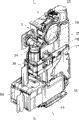
图18是示出基于本发明的第一实施例的图像稳定器的透视图,并且从前侧示出了该图像稳定器;FIG. 18 is a perspective view showing the image stabilizer according to the first embodiment of the present invention, and shows the image stabilizer from the front side;
图19是从后侧示出的示于图18中的图像稳定器的透视图;FIG. 19 is a perspective view of the image stabilizer shown in FIG. 18 shown from the rear side;
图20是示于图18中的图像稳定器的平面图;Fig. 20 is a plan view of the image stabilizer shown in Fig. 18;
图21是示于图18中的图像稳定器的前视图;Fig. 21 is a front view of the image stabilizer shown in Fig. 18;
图22是示于图18中的图像稳定器的后视图;Fig. 22 is a rear view of the image stabilizer shown in Fig. 18;
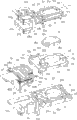
图23是示于图18中的图像稳定器的分解透视图;FIG. 23 is an exploded perspective view of the image stabilizer shown in FIG. 18;
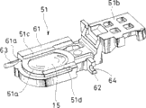
图24是示出示于图18中的图像稳定器的第一运动框的透视图;FIG. 24 is a perspective view showing a first motion frame of the image stabilizer shown in FIG. 18;
图25是示出示于图18中图像稳定器的线圈组件主体、磁铁和轭的分解透视图;25 is an exploded perspective view showing a coil assembly main body, a magnet and a yoke of the image stabilizer shown in FIG. 18;
图26是以放大比例示出示于图18中的图像稳定器的线圈组件主体、磁铁和轭的平面图;FIG. 26 is a plan view showing, on an enlarged scale, a coil assembly main body, a magnet, and a yoke of the image stabilizer shown in FIG. 18;
图27是以放大比例示出示于图18中的图像稳定器的线圈组件主体、磁铁和轭的前视图;FIG. 27 is a front view showing, on an enlarged scale, a coil assembly main body, a magnet, and a yoke of the image stabilizer shown in FIG. 18;
图28是基于本发明第二实施例的图像稳定器的线圈组件主体、磁铁和轭的平面图;28 is a plan view of a coil assembly main body, a magnet, and a yoke of an image stabilizer according to a second embodiment of the present invention;
图29是基于本发明第三实施例的图像稳定器的线圈组件主体、磁铁和轭的平面图;29 is a plan view of a coil assembly main body, a magnet, and a yoke of an image stabilizer according to a third embodiment of the present invention;
图30是示于图29中的线圈组件主体、磁铁和轭的分解透视图;Figure 30 is an exploded perspective view of the coil assembly main body, magnet and yoke shown in Figure 29;
图31是用于解释基于本发明一实施例的图像稳定器将受到控制的概念的框图;31 is a block diagram for explaining the concept that an image stabilizer based on an embodiment of the present invention will be controlled;
图32是示出基于本发明一实施例的成像器装置的示意性设置的第一实施例的框图;32 is a block diagram showing a first embodiment of a schematic setup of an imager device according to an embodiment of the present invention;
图33是示出基于本发明一实施例的成像器装置的示意性设置的第二实施例的框图;33 is a block diagram showing a second embodiment of a schematic setup of an imager device according to an embodiment of the present invention;
图34是示出基于本发明一实施例的运动磁铁系统图像稳定器的透视图;34 is a perspective view showing a moving magnet system image stabilizer according to an embodiment of the present invention;
图35是示出示于图34中的图像稳定器的分解透视图;FIG. 35 is an exploded perspective view showing the image stabilizer shown in FIG. 34;
图36A和36B分别是示出示于图34中的图像稳定器的图示,其中图36A是其平面图,而图36B是其仰视图;36A and 36B are diagrams showing the image stabilizer shown in FIG. 34, respectively, wherein FIG. 36A is a plan view thereof, and FIG. 36B is a bottom view thereof;
图37A、37B、37C和37D分别是示出示于图34中的图像稳定器的图示,其中图37A是其前视图,图37B是其后视图,图37C是其右手侧主视图,图37D是其左手侧主视图;37A, 37B, 37C and 37D are illustrations showing the image stabilizer shown in FIG. 34, respectively, wherein FIG. 37A is its front view, FIG. 37B is its rear view, FIG. 37C is its right-hand side front view, and FIG. 37D is its left-hand front view;
图38是示出基于本发明一实施例的运动霍尔元件系统图像稳定器的透视图;FIG. 38 is a perspective view showing a moving Hall element system image stabilizer according to an embodiment of the present invention;
图39是示出示于图38中的图像稳定器的分解透视图;FIG. 39 is an exploded perspective view showing the image stabilizer shown in FIG. 38;
图40A和40B分别是示出示于图38中的图像稳定器的图示,其中图40A是其平面图,而图40B是其仰视图;40A and 40B are diagrams showing the image stabilizer shown in FIG. 38, respectively, wherein FIG. 40A is a plan view thereof, and FIG. 40B is a bottom view thereof;
图41A、41B、41C和41D分别是示出示于图38中的图像稳定器的图示,其中图41A是其前视图,图41B是其后视图,图41C是其右手侧主视图,图41D是其左手侧主视图;41A, 41B, 41C and 41D are diagrams showing the image stabilizer shown in FIG. 38, respectively, wherein FIG. 41A is its front view, FIG. 41B is its rear view, FIG. 41C is its right-hand side front view, and FIG. 41D is its left-hand front view;
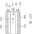
图42A、42B、42C和42D分别是用于解释基于本发明一实施例的磁铁、轭和霍尔元件之间关系的图示,其中图42A是轭和磁铁的平面图,图42B是其纵向截面图,图42C是示出该轭、磁铁、霍尔元件和线圈之间关系的说明图,以及图42D是示出该霍尔元件和线圈之间关系的说明图;42A, 42B, 42C and 42D are respectively diagrams for explaining the relationship between magnets, yokes and Hall elements based on an embodiment of the present invention, wherein FIG. 42A is a plan view of a yoke and a magnet, and FIG. 42B is a longitudinal section thereof 42C is an explanatory diagram showing the relationship between the yoke, the magnet, the Hall element, and the coil, and FIG. 42D is an explanatory diagram showing the relationship between the Hall element and the coil;
图43A和43B分别是示出当通过图42C中示出的霍尔元件检测磁通密度时所获结果的图表,其中图43A示出了当在轭具有凸出部分的状态下通过霍尔元件检测磁通密度时获得的结果,而图43B示出了当在轭不具有凸出部分的状态下通过霍尔元件检测磁通密度时获得的结果;43A and 43B are graphs showing the results obtained when the magnetic flux density is detected by the Hall element shown in FIG. 42C, wherein FIG. The results obtained when detecting the magnetic flux density, while FIG. 43B shows the results obtained when the magnetic flux density is detected by the Hall element in the state where the yoke has no protruding portion;
图44A和44B分别是示出当通过图43A和43B中示出的霍尔元件检测磁通密度时所获结果的图表,其中图44A示出了当在轭具有凸出部分的状态下通过霍尔元件检测磁通密度时获得的结果,而图44B示出了当在轭不具有凸出部分的状态下通过霍尔元件检测磁通密度时获得的结果;44A and 44B are graphs showing the results obtained when the magnetic flux density is detected by the Hall element shown in FIGS. 43A and 43B, respectively, wherein FIG. 44B shows results obtained when the magnetic flux density is detected by the Hall element in a state where the yoke does not have a protruding portion;
图45是用于解释通过图42C所示的霍尔元件检测磁通密度的状态的说明图;FIG. 45 is an explanatory diagram for explaining a state in which magnetic flux density is detected by the Hall element shown in FIG. 42C;
图46A、46B和46C分别是用于解释通过示于图45中的霍尔元件检测磁通密度的状态的图示,其中图46A是用于解释没有凸出部分的短侧的侧面的图示,图46B是用于解释具有凸出部分的短侧的侧面的图示,而图46C是用于解释长侧的侧面的图示。46A, 46B and 46C are diagrams for explaining the state of detecting the magnetic flux density by the Hall element shown in FIG. 45 , respectively, wherein FIG. 46A is a diagram for explaining the side of the short side without the protruding portion , FIG. 46B is a diagram for explaining the side of the short side having the convex portion, and FIG. 46C is a diagram for explaining the side of the long side.
具体实施方式 Detailed ways
下面将参考附图描述本发明的实施例。图1至图46A、46B和46C是用于解释本发明实施例的图示。Embodiments of the present invention will be described below with reference to the drawings. 1 to 46A, 46B and 46C are diagrams for explaining an embodiment of the present invention.
图1是从前侧示出的基于本发明的第一实施例的透镜装置的透视图。图2是从后侧示出该透镜装置的透视图。图3是其前视图。图4是其后视图。图5是其左手侧正视图。图6是其右手侧正视图。图7是其平面图。图8是其仰视图。图9是沿图5中的线M-M的截面图。图10是沿图3中的线N-N的截面图。图11是其分解透视图。图12是用于解释透镜系统的图示。图13是示出成像器装置的第一示例的数字照相机的分解透视图。图14是从前侧示出数字照相机的透视图。图15是示出通过移动透镜盖使物镜露出的状态的透视图。图16是其后视图而图17是其平面图。Fig. 1 is a perspective view of a lens device based on a first embodiment of the present invention shown from the front side. Fig. 2 is a perspective view showing the lens device from the rear side. Fig. 3 is its front view. Fig. 4 is its rear view. Figure 5 is a left-hand front view thereof. Figure 6 is a right-hand front view thereof. Fig. 7 is its plan view. Fig. 8 is its bottom view. FIG. 9 is a cross-sectional view along line M-M in FIG. 5 . FIG. 10 is a cross-sectional view along line N-N in FIG. 3 . Fig. 11 is an exploded perspective view thereof. FIG. 12 is a diagram for explaining a lens system. Fig. 13 is an exploded perspective view of a digital camera showing a first example of an imager device. Fig. 14 is a perspective view showing the digital camera from the front side. Fig. 15 is a perspective view showing a state in which the objective lens is exposed by moving the lens cover. Fig. 16 is its rear view and Fig. 17 is its plan view.
图18是从前侧示出基于本发明的第一实施例的图像稳定器的透视图。图19是从后侧示出本图像稳定器的透视图。图20是其平面图。图21是其前视图,图22是其后视图而图23是其分解透视图。图24是示出第一运动框的透视图。图25是示出线圈组件主体、磁铁和轭的分解透视图。图26是示出线圈组件主体等的俯视图。图27是其前视图。图28是示出基于本发明第二实施例的线圈组件主体、磁铁和轭的平面图。图29是示出基于本发明第三实施例的线圈组件主体等的透视图。图30是其分解透视图。图31是用于解释对基于本发明一实施例的图像稳定器进行控制的概念的框图。图32是示出基于本发明第一实施例的成像器装置的示意性设置的框图。图33是示出基于本发明第二实施例的成像器装置的示意性设置的框图。Fig. 18 is a perspective view showing the image stabilizer according to the first embodiment of the present invention from the front side. Fig. 19 is a perspective view showing the present image stabilizer from the rear side. Fig. 20 is its plan view. Fig. 21 is a front view thereof, Fig. 22 is a rear view thereof and Fig. 23 is an exploded perspective view thereof. FIG. 24 is a perspective view showing a first motion frame. Fig. 25 is an exploded perspective view showing a coil assembly main body, a magnet and a yoke. Fig. 26 is a plan view showing the coil assembly main body and the like. Fig. 27 is its front view. Fig. 28 is a plan view showing a coil assembly main body, a magnet, and a yoke according to a second embodiment of the present invention. Fig. 29 is a perspective view showing a coil component main body and the like according to a third embodiment of the present invention. Fig. 30 is an exploded perspective view thereof. FIG. 31 is a block diagram for explaining the concept of controlling an image stabilizer based on an embodiment of the present invention. Fig. 32 is a block diagram showing a schematic arrangement of an imager device based on the first embodiment of the present invention. Fig. 33 is a block diagram showing a schematic arrangement of an imager device based on a second embodiment of the present invention.
图34至图46A、46B和46C分别用于解释磁铁的磁力与作为位置检测器来检测该磁铁的磁力的霍尔元件之间的关系的图示。在图34至图42A、42B和42C中,没有示出构成驱动器一部分的线圈,以便更容易理解每幅视图。34 to 46A, 46B, and 46C are diagrams each for explaining the relationship between the magnetic force of a magnet and a Hall element that detects the magnetic force of the magnet as a position detector. In Figures 34 to 42A, 42B and 42C, the coils forming part of the driver are not shown to make each view easier to understand.
特别是,图14至图37A、37B、37C和37D示出了将本发明应用到包含移动磁铁系统驱动器的图像稳定器上的实例,其中驱动器的线圈与两个霍尔元件是固定的,该磁铁是可动的。图34是示出该图像稳定器外观的透视图。图35是其分解透视图,图36A是其平面图,图36B是其仰视图,图37A是其前视图,图37B是其后视图,图37C是其右手侧主视图而图37D是其左手侧主视图。图38至41A、41B、41C和41D示出了将本发明用于装备有移动线圈(移动霍尔元件)系统驱动器的图像稳定器的实例,其中该驱动器的磁铁是固定的,两个霍尔元件是可动的。图38是示出该图像稳定器的外观的透视图,图39是其分解透视图,图40A是其平面图,图40B是其仰视图,图41A是其前视图,图41B是其后视图,图41C是其右手侧主视图和图41D是其左手侧主视图。In particular, FIGS. 14 to 37A, 37B, 37C, and 37D show an example of applying the present invention to an image stabilizer comprising a moving magnet system driver in which the coil and the two Hall elements are fixed, the The magnet is movable. Fig. 34 is a perspective view showing the appearance of the image stabilizer. Fig. 35 is an exploded perspective view thereof, Fig. 36A is a plan view thereof, Fig. 36B is a bottom view thereof, Fig. 37A is a front view thereof, Fig. 37B is a rear view thereof, Fig. 37C is a right-hand front view thereof and Fig. 37D is a left-hand side thereof main view. 38 to 41A, 41B, 41C and 41D show an example of applying the present invention to an image stabilizer equipped with a moving coil (moving Hall element) system driver, where the magnet of the driver is fixed, and the two Hall elements Components are movable. 38 is a perspective view showing the appearance of the image stabilizer, FIG. 39 is an exploded perspective view thereof, FIG. 40A is a plan view thereof, FIG. 40B is a bottom view thereof, FIG. 41A is a front view thereof, and FIG. 41B is a rear view thereof, Figure 41C is its right-hand front view and Figure 41D is its left-hand front view.
图42A、42B、42C和42D分别是用于解释磁铁、轭和两个霍尔元件等之间位置关系的图示,其中图42A是磁铁和轭的平面图,图42B是其纵向截面图,图42C是示出该磁铁、轭、线圈和两个霍尔元件之间位置关系的说明图,以及图42D是示出该线圈和两个霍尔元件之间位置关系的说明图,同时省略了磁铁和轭。图43A和43B是示出在轭包括凸出部分的情况下通过霍尔元件检测磁通密度与在轭不包括凸出部分的情况下通过霍尔元件检测的磁通密度的值之间差异的图表。图43A是示出当轭包括凸出部分时获得的检测值的图表,图43B是示出当轭不包括凸出部分时获得的检测值的图表,并且图44A和44B是以曲线的形式示出示于图43A和43B中的检测值的说明图。图45是示出霍尔元件相对于磁铁的位置与磁通密度之间关系的说明图,并且图46A、46B和46C是示出将示于图45的关系应用到特定位置的情况下的说明图。42A, 42B, 42C, and 42D are diagrams for explaining the positional relationship between the magnet, the yoke, and two Hall elements, etc., respectively, wherein FIG. 42A is a plan view of the magnet and the yoke, and FIG. 42B is a longitudinal sectional view thereof. 42C is an explanatory diagram showing the positional relationship between the magnet, the yoke, the coil, and the two Hall elements, and FIG. 42D is an explanatory diagram showing the positional relationship between the coil and the two Hall elements, while omitting the magnet. and yoke. 43A and 43B are graphs showing the difference between the value of the magnetic flux density detected by the Hall element in the case where the yoke includes a protrusion and the value of the magnetic flux density detected by the Hall element in the case where the yoke does not include a protrusion. chart. 43A is a graph showing detected values obtained when the yoke includes a protruding portion, FIG. 43B is a graph showing detected values obtained when the yoke does not include a protruding portion, and FIGS. 44A and 44B are graphs showing Explanatory diagrams of the detection values shown in FIGS. 43A and 43B are shown. 45 is an explanatory diagram showing the relationship between the position of the Hall element with respect to the magnet and the magnetic flux density, and FIGS. 46A, 46B, and 46C are illustrations showing a case where the relationship shown in FIG. 45 is applied to a specific position picture.
如图1至11所示,透镜装置1示出了基于本发明第一实施例的透镜装置。该透镜装置1包括透镜系统2、透镜筒3、CCD((charge-coupled device电荷耦合装置),也就是固体成像装置)4、图像稳定器5等,该透镜系统2包括5组具有多个位于相同光轴L上的透镜,该透镜筒3用于固定该透镜系统2的透镜或支撑该透镜系统2的透镜使得它们可以成为可动的,该CCD4示出固定到透镜的透镜筒3的成像器的特定实例,该图像稳定器5安装到该透镜筒3上并可以使透镜系统2的图像稳定。As shown in FIGS. 1 to 11 , the
透镜装置1的透镜系统2构造为折叠透镜,其由具有位于同一光轴L上的五套透镜组的五组透镜7至11构成。五组透镜7至11中,位于末端侧的第一组透镜7由第一透镜7A、棱镜7B和第二透镜7C构成,该第一透镜7A是与物体相对的物镜,该棱镜7B位于物镜7A的与该物体相对的一侧上,该第二透镜7C与棱镜7B相对。棱镜7B是其截面为等腰直角三角形的三棱镜。物镜7A与位置偏移90度相邻的两个表面中的一个相对,而第二透镜7C与另一表面相对。The
在第一组透镜7中,从一个表面通过物镜7A引入棱镜7B的光在相对于光轴L倾斜45度的反射表面上被反射,并由此其传播方向弯曲90度。然后,该光从另一表面射出,穿过第二透镜7C并朝向沿光轴L的第二组透镜8传播。该第二组透镜8通过第三透镜8A和第四透镜8B组合构成,由此成为在光轴L上是可动的。将穿过该第二组透镜8的光引入到第三组透镜9。In the
该第三组透镜9包括固定到透镜的透镜筒3的第五透镜。由第六透镜构成的第四组透镜10位于该第三组透镜9的后面。能够调节穿过透镜系统2的光量的可变光阑机构12位于该第四组透镜10和第三组透镜9之间。该第四组透镜10构造为使得能够移动光轴L。由第七透镜11A和校正透镜15构成的第五组透镜11位于该第四组透镜10的后面,这将在后面进行描述。在该第五组透镜11中,第七透镜11A固定到透镜的透镜筒3,并且校正透镜15位于第七透镜11A的后面以便其能够移动。另外,CCD4位于校正透镜15的后面。This third group of
该第二组透镜8和第四组透镜10能够分开并独立地沿光轴L朝向光轴方向移动。用户通过沿预定方向移动该第二组透镜8和该第四组透镜10能够对变焦和聚焦进行调节。更特别的是,在变焦调节方面,用户能够通过移动该第二组透镜8和该第四组透镜10而从广角到远距照相进行变焦调节。在聚焦调节方面,用户能够通过移动该第四组透镜10从广角到远距照相进行聚焦调节。The second group of
CCD4固定到CCD适配器上,并且通过该CCD适配器将其连接到透镜的透镜筒3。光学滤波器14位于CCD4的前面,并且包含该校正透镜15的图像稳定器5位于该光学滤波器14和该第七透镜11A之间。将在后面进行详细描述的图像稳定器5适于对因透镜系统2的运动和振动而在拍摄的图像上产生的模糊图像进行校正。在普通状态下,校正透镜15以其光轴与透镜系统2的光轴L相匹配的方式接合。当由于相机主体等的运动和振动使CCD4的聚焦屏上的图1像模糊时,图像稳定器5能够通过沿垂直于光轴L的两个方向(第一方向X和第二方向Y)移动校正透镜15而校正CCD4的聚焦屏上的模糊图像。The
固定具有上述设置的透镜系统2的透镜的透镜筒3由上镜筒16、中镜筒17和下镜筒18构成,其能够如图1至11所示沿上下方向组装并结合。上镜筒16由开口窗19和壳体构成,该开口窗19在前面的上部开口,该壳体具有在下表面内开口的开口部分。该第一组透镜7的物镜7A安装到该开口窗19上,并且物镜7A通过安装到该开口窗19的前面上的面板21安装到上镜筒18。穿过遮光板22位于物镜7A后面的棱镜7B和位于该棱镜7B的下表面上的第二透镜7C固定在上镜筒16内。The
在该上镜筒16内,第一可动固定框23以能够沿与在透镜的透镜筒3的上下方向上延伸的透镜系统2的光轴L平行的上下方向上移动的方式被支撑。第一可动固定框23具有穿过该上下方向的通孔,并且该第二组透镜8固定到该通孔。第一可动固定框23通过连接到上镜筒16的变焦驱动机构24以能够在沿透镜系统2的光轴L的方向上在预定范围内向前和向后移动的方式进行配置。In the
该变焦驱动机构24由变焦电机25、提供作为变焦电机25的旋转轴的进给螺杆轴26、与该进给螺杆轴26啮合的进给螺母27等构成。变焦电机25固定到U形第一支架28,并且一端凸出的该进给螺杆轴26的两端部分由第一支架28支撑,以便能够自由地旋转。该第一支架28通过多个固定螺钉29a(在本实施例中是两个固定螺钉29a)连接到上镜筒16,其示出了紧固机构的一个特定实例。The
在第一支架28连接到上镜筒16的状态下,进给螺母27可滑动地与进给螺杆轴26啮合。进给螺母27在其可被限定为不沿其螺纹槽延伸的方向运动的状态下由该第一可动固定框23固定。另外,该第一可动固定框23具有在其上钻孔的两个导引轴31a和31b,以便沿平行于光轴L的方向可滑动。将该两导引轴31a和31b的一端固定到上镜筒16,而其另一端固定到中镜筒17。In a state where the
于是,当驱动变焦电机25时,进给螺杆轴26的旋转力通过进给螺母27传送到第一可动固定框23。这时,相对于在预定位置旋转的进给螺杆轴26,进给螺母27沿轴向相对移动。结果,第一可动固定框23与进给螺母27一起移动,由此使该第二组透镜8响应于该变焦电机25的旋转方向沿其趋近于该第一组透镜7的方向或沿其趋近于该第三组透镜9的方向选择性地移动。这时,由于该两导引轴31a和31b沿平行于光轴L的方向对固定该第二组透镜8的第一可动固定框23进行导引,因此该第一可动固定框23能够在光轴L上以高精度移动。Then, when the
位于牢固地固定到该中镜筒17上的该第三组透镜9下方的可变光阑机构12由光阑元件32、光阑支撑板33,步进电机34等构成,该光阑元件32的开口面积可被自由地调节,该光阑支撑板33用于可动地支撑该光阑元件32,该步进电机34用于打开和关闭该光阑元件32。步进电机34通过电机基底35固定到中镜筒17的上表面的侧面部分。中镜筒17放置在下镜筒18上,而上镜筒16放置在中镜筒17上。这三个镜筒16、17和18通过穿透这些镜筒16、17和18的多个固定螺钉29b(在本实施例中是三个固定螺钉29b、29b,29b)沿上下方向紧固并固定在一起,并由此集成组装为透镜的透镜筒3。The
下镜筒18由在上表面、侧表面和下表面开口的壳体形成。在下镜筒18的壳体内,支撑着第二可动固定框36,其能够沿平行于透镜系统2的光轴L的上下方向移动。第二可动固定框36具有在其上钻出的沿上下方向的通孔,并且该第四组透镜10固定到该通孔。第二可动固定框36构造为使得其通过连接到下镜筒18的聚焦驱动机构37能够在沿透镜系统2的光轴L方向上在预定范围内向前和向后移动。The
聚焦驱动机构37包括聚焦电机38、提供作为该聚焦电机38的旋转轴的进给螺杆轴39、与该进给螺杆轴39啮合的进给螺母41等构成。聚焦电机38固定到U形第二支架42,并且凸出到第二框架42的一端的进给螺杆轴39的各个端部通过该第二框架42在各端可旋转地支撑。第二框架42通过用作紧固机构的多个固定螺钉29c(两个固定螺钉29c,29c)连接到下镜筒18。The
在第二框架42连接到下镜筒18的状态下,进给螺母41可滑动地与进给螺杆轴39啮合。在进给螺母41被限定为在不沿其螺纹槽延伸的方向运动的状态下,进给螺母41固定到第二可动固定框36。另外,两导引轴43(在图11中仅示出一个导引轴43)沿平行于光轴L的方向可滑动地穿透第二可动固定框36。该两导引轴43的一端固定到中镜筒17,而其另一端固定到下镜筒18。In a state where the
于是,当驱动聚焦电机38时,进给螺杆轴39的旋转力通过进给螺母41传送到第二可动固定框36。这时,进给螺母41沿在预定位置旋转的进给螺杆轴39的轴向相对运动。结果,第二可动固定框36与进给螺母41一致运动,由此该第四组透镜10响应于聚焦电机38的旋转方向选择性地沿趋近于该第三组透镜9的方向和趋近于该第五组透镜11的方向运动。这时,由于固定该第四组透镜10的第二可动固定框36被该两导引轴43沿平行于光轴L的方向导引,因此其能够高精度地在光轴L上运动。Then, when the
CCD4通过CCD适配器44接合到下镜筒18的下表面。CCD适配器4由具有钻孔于其中心部分的方形开口孔的板体构成,并且通过例如粘接剂等的紧固机构穿过方形框架状的密封橡胶45将CCD4集成固定到CCD适配器44的一个表面。其上结合有滤光器14的遮光板46设置在CCD适配器44的另一个表面。CCD适配器44和遮光板46通过滤光压板47加压,并由此固定在一起。然后,在滤光器14位于内侧的状态下,通过诸如固定螺钉的紧固机构将CCD适配器44接合到下镜筒18。The
图像稳定器5可分离地接合到在该下镜筒18的侧表面内开口的开口部分48。图像稳定器5具有示于图18至27的设置。该图像稳定器5包括上述校正透镜15,用于支撑该校正透镜15的第一移动框51,和用于以该第一移动框51能够沿垂直于透镜系统2的光轴L的第一方向X移动的方式支撑该第一移动框51的第二移动框52。还包括用于沿垂直于光轴L并且垂直于该第一方向X的第二方向Y支撑该第二移动框52的固定基底53,示出为用于使第一移动框51沿第一方向X移动以及使第二移动框52沿第二方向Y移动的驱动器的特定实例的传动装置(actuator)54,用于检测校正透镜15的位置的位置检测器94、95等。The
当由于将在下文中描述的手抖动而使照相机主体抖动或振动时,校正透镜15响应于该照相机主体抖动量沿第一方向X或第二方向Y移动其位置,由此使图像稳定。如图23所示,校正透镜15在其外周边缘形成沿圆周在一个表面侧连续的台阶部分15a。另外,与直径方向对应的两个凹槽形成在校正透镜15的外周边缘,由此形成两面宽度部分15a和15b。该校正透镜15固定到第一移动框51,该第一移动框51示出了移动框的第一实例。When the camera body shakes or vibrates due to hand shake to be described below, the
如图23和24所示,第一移动框51由环形透镜固定部分51a、曲柄状轭固定部分51b等构成,校正透镜15装配到该环形透镜固定部分51a中,曲柄状轭固定部分51b连续地形成于该透镜固定部分51a的一侧并且轭66固定到其上。透镜固定部分51a具有与校正透镜15相对应的形状,并且与校正透镜15的台阶部分15a相啮合的台阶部分设置在适配孔58的外围边缘,校正透镜15装配到该适配孔58中。另外,透镜固定部分51a包括与校正透镜15的两表面宽度部分15a和15b相对应的两表面宽度部分51c和51d,并且轭固定部分51b连接到与该两表面宽度部分51c和51d相对的方向(第二方向Y)垂直的方向(第一方向X)的一侧。As shown in FIGS. 23 and 24, the first moving
第一主轴承部分61和第一次轴承部分62设置在透镜固定部分51a的两表面宽度部分51c和51d的外侧。该第一主轴承部分61包括以预定间隔沿第一方向X设置的两个轴承件61a和61b。第一主导引轴63沿第一方向X穿过该两轴承件61a和61b。第一主导引轴63通过压配合插入并固定到该两轴承件61a和61b。第一主导引轴63的各个端部分别从轴承件61a和61b凸出到外侧。沿侧向开口的轴承槽64穿透第一次轴承部分62。第一次导引轴65可滑动地嵌入该轴承槽64。The first
构成传动装置54的一部分的轭66通过诸如粘接剂和固定螺钉的紧固机构固定到第一移动框51的轭固定部分51b。如图25所示,轭66由其间具有预定间隔彼此平行相对的上部件66a和下部件66b以及连接该上、下部件66a和66b的连接件66c构成。连接件66c设置在该上、下部件66a和66b的纵向一侧,并且凹陷66d形成在连接件66c的侧面方向,该第一移动框51的轭固定部分51b的一部分插入到该凹陷66d中。The
设置轭66的凹陷66d以便使线圈组件主体94更靠近校正透镜15,线圈组件主体94将在下面描述。该凹陷66d使传动装置54更小型化成为可能。尺寸基本上与上部件66a和下部件66b相等的矩形平面磁铁67a和67b通过诸如粘接剂的紧固机构分别固定到轭66的上部件66a和下部件66b的两个内表面。沿上下方向相对的两磁铁67a和67b和轭66构成一磁路。特别是,由一个轭66和两个磁铁67a和67b构成的一套磁路元件既用作第一驱动器的磁路,也用作第二驱动器的磁路。The
如图23所示,示出为移动框的第二特定实例的第二移动框52由比第一移动框51稍宽的平板主体形成。第二移动框52与第一移动框的下侧相对并装配到其上。第二移动框52具有在与第一移动框51的适配孔58相对的位置穿透的与该第一适配孔58尺寸基本上相同的通孔68。第二轴承部分设置在第二移动框52的上表面上,以便支撑该第一移动框51,使得该第一移动框51能够沿第一方向X滑动。As shown in FIG. 23 , the second moving
第二轴承部分由第二主轴承部分71和第二次轴承部分72构成,第二主轴承部分71用于可滑动地支撑固定到该第一移动框51的第一主导引轴63,该第二次轴承部分72用于固定地支撑该第一次导引轴65。第二主轴承部分71位于在第一移动框51设置在第二移动框52上方的状态下能够支撑该第一主导引轴63的各个端部的位置。特别是,第二主轴承部分71由两个轴承件71a和71b构成,以支撑该第一主导引轴63的各个端部并且被设置成在该第二移动框52的上表面上向上凸出。The second bearing portion is composed of a second
第二主轴承部分71的两轴承件71a和71b间隔一距离,该距离通过将第一移动框51沿第一方向X运动的足够长的长度加上第一主轴承部分61沿该第一方向X延伸的长度得到。该两轴承件71a和71b具有钻孔在其上的轴承孔,并且第一主导引轴63的两端部分别可滑动地插入到这些轴承孔中。The two
同样,第二次轴承部分72在第一移动框51设置在第二移动框52上方的状态下位于与该第一次轴承部分62相对应的位置。特别是,第二次轴承部分72由用于支撑第一次导引轴65的各个端部的两个轴承件72a和72b构成。该两轴承件72a和72b具有钻孔在其上的轴承孔,并且第一次导引轴65的两端部分别通过压配合插入并固定到这些轴承孔中。第一次导引轴65可滑动地插入到形成在第一移动框51的第一次轴承部分62上的轴承槽64中。设置第一次导引轴65和第一主导引轴63,使得其轴线可以彼此平行。第一移动框51被第一次导引轴65和第一主导引轴63导引,使得其能够沿第一方向X运动。Also, the second secondary bearing
将第三轴承部分设置在第二移动框52的下表面上,以便支撑该第二移动框52,使得第二移动框52能够沿垂直于第一方向X的第二方向Y滑动。第三轴承部分由第三主轴承部分75和第三次轴承部分76构成。第三次轴承部分75由位于第二移动框52的第一方向X的一个端部处并且其间沿第二方向Y以预定间隔定位的两个轴承件75a和75b构成。该两轴承件75a和75b分别具有在其上钻出的轴承孔,并且沿第二方向Y延伸的第二主导引轴77的两个端部分别可滑动地插入这些轴承孔。A third bearing portion is provided on the lower surface of the second moving
同样,将第三次轴承部分76设置到第二移动框52上其第一方向X的另一端部的基本上中心部分。沿侧向开口的轴承槽78设置在该第三次轴承部分76上。沿垂直于第一方向X的第二方向Y延伸的第二次导引轴79可滑动地啮合该轴承槽78。第二主导引轴77和第二次导引轴79分别固定到固定基底53。固定基底53示出了支撑框的特定实例,并且第二移动框52与该固定基底53相对并组装到其上。Also, the third
如图23所示,固定基底53由尺寸与第二移动框52相对应的移动框支撑部分53a、与该移动框支撑部分53a连续形成为一体的线圈固定部分53b等构成。移动框支撑部分53a由尺寸基本上与第二移动框52相同的平板主体形成,并且线圈固定部分53b沿第一方向X延续到该移动框支撑部分53a的一端。移动框支撑部分53a在其与第二移动框52的通孔69相对应的位置处具有与第二移动框52的通孔68尺寸基本上相同的通孔81。第四轴承部分以能够使第二移动框52沿第二方向Y滑动穿过第二导引轴的方式设置到移动框支撑部分53a的上表面上沿第一方向X的各端部处。As shown in FIG. 23, the fixed
第四轴承部分由位于第一方向X的一侧上的第四主轴承部分82和位于第一方向X的另一侧上的第四次轴承部分83构成。第四主轴承部分82由沿第二方向Y具有适当间距的两个轴承件82a和82b构成,并且它们在移动框支撑部分53a的上表面上向上凸出。两个轴承件82a和82b具有分别钻孔在其上的轴承孔,并且第二主导引轴77的两个轴向方向中间部分通过压配合插入并固定到这些轴承孔中。因此,第二主导引轴77的各个端部分别朝两个轴承件82a和82b的外侧凸出。The fourth bearing portion is composed of a fourth
设置在第二移动框52上的第三主轴承部分75的两个轴承件75a和75b可滑动地与第二主导引轴77的两端的凸出部分啮合。两轴承件75a和75b分隔一段距离,该距离由将第二移动框52沿第二方向Y移动的足够长的长度加上两轴承件82a和82b的长度得到。因此,将第二移动框52的第三主轴承部分75支撑到固定在固定基底53的第四主轴承部分82上的第二主导引轴77上,使得其能够在两轴承件82a和82b的外侧运动。Two bearing
同样,第四次轴承部分83由沿第二方向Y设置的其间具有适当间距的两个轴承件83a和83b构成,并且设置它们以便向上凸出到移动框支撑部分53a的上表面。两轴承件83a和83b具有钻孔在其上的轴承孔。第二次导引轴79通过压配合插入并固定到这些轴承孔中,并由此沿轴向支撑在它们的各端部。在两轴承件83a和83b之间,设置在第二移动框52上的第三次轴承部分76的轴承槽78可滑动地与第二次导引轴79啮合。因此,第三次轴承部分76被两轴承件83a和83b之间的第二次导引轴79导引,以便其能够沿第二方向Y移动预定距离。Also, the
固定基底53的线圈固定部分53b由具有沿向上方向突出的支撑壁84的基本上方形平面部分形成,并且该支撑壁84位于该第二方向Y的一侧。线圈支撑固定器85固定到线圈固定部分53b,并且线圈组件主体93接合到线圈支撑固定器85。如图25所示,设置线圈支撑固定器85以便将线圈组件主体93固定在预定高度,并且其形成为具有U型平面的框架主体。线圈支撑固定器85设置在线圈固定部分53b上,以便沿该支撑壁84延伸,并且其通过诸如粘接剂和固定螺钉的紧固机构集成地固定到固定基底53。用于将固定基底53固定到透镜的透镜筒3的附件套筒部分53c设置在固定基底53的下表面上。The
线圈支撑固定器85的上表面形成为平面,并且将用于适当地定位柔性加强板86的两定位凸出部分85a和85b设置到线圈支撑固定器85的上表面上。两定位凸出部分85a和85b沿第二方向Y以预定间隔定位,并且通过该两定位凸出部分85a和85b适当定位的柔性加强板86固定到线圈支撑固定器85的上表面。在上下表面内印刷并模制有预定电路的柔性印刷电路板87通过诸如粘胶带的紧固机构固定到柔性加强板86上。The upper surface of the
具有平面绕线的平面线圈83安装在柔性加强板86的上表面上,并且其电连接到设置在该柔性印刷电路板87的上表面上的预定布线图案。如图25等所示,平面线圈88具有两椭圆形线圈部分88a和88b肩并肩设置的形状。两线圈部分88a和88b沿宽度方向的长度基本上相同,但是其沿纵向的长度不同。两线圈部分88a和88b沿纵向的长度不同的原因在于轭66的连接件66c能够位于较短的线圈部分88b的外侧,使得其能够接近校正透镜15,同时保持平面线圈88的平坦表面侧宽的面积,由此使整个传动装置54的小型化成为可能。A
该两个线圈部分88a和88b是通过缠绕同一线圈线而形成的,并且以这种方式设置同一线圈线的缠绕方向以使得当激励平面线圈88时,电流在推力产生部分89a和89b中沿相同方向流动,该推力产生部分89a和89b的在宽度方向相邻的长侧直线延伸。在两个线圈部分88a和88b的纵向定向为第二方向Y的状态下,平面线圈88通过例如粘接剂的紧固机构固定在柔性加强板86上。这样,当电流流过两个线圈部分88a和88b时,由于从磁铁67a和67b产生的磁力作用于垂直于平面线圈88的方向,由于弗莱明(Fleming)左手定律,定向为沿第一方向X的力作用于磁铁67a和67b的侧面。The two
圆柱形线圈91连接在柔性加强板86的底面,并且该圆柱形线圈91的两端电连接于设置在柔性印刷电路板87的底面上的预定布线图案。如图25等所示,该圆柱形线圈91包括设置在其中央部分上的矩形空间部分以使得其整体形成矩形圆筒,并且通过缠绕预定数量的线圈线来提供叠层方向的预定厚度以使其形状像正方形圆筒。在将线圈线延伸的方向定向为第一方向X的状态下,该圆柱形线圈91具有通过例如粘接剂之类的紧固机构固定在柔性印刷电路板87上的推力产生部分92。A
整体地紧固成具有下部件66b的一个主体的轭66的下部件66b和下面磁铁67b可以插入圆柱形线圈91的中央空间部分。这样,当电流流过圆柱形线圈91时,由于从磁铁67a和67b产生的磁力作用在垂直于推力产生部分92的方向,由于弗莱明的左手定律,向着第二方向Y定向的力作用于磁铁67a和67b的侧面。柔性加强板86,柔性印刷电路板87,平面线圈88和圆柱形线圈91构成线圈组件主体93。The
图26和27示出的是由上述线圈组件主体93,轭66和两个磁铁67a和67b构成的传动装置54。传动装置54中,轭66,两个磁铁67a和67b以及平面线圈88构成使校正透镜15沿第一方向X穿过第一移动框51运动的第一驱动器。然后,第一移动框51的第一主轴承部分61和第一次轴承部分62,第一主导引轴63和第一次导引轴65,第二主轴承部分71和第二次轴承部分72构成使校正透镜15沿垂直于透镜装置1的光轴L的第一方向X穿过第一移动框51运动的第一导轨。26 and 27 show the actuator 54 constituted by the above-mentioned coil assembly
此外,轭66,两个磁铁67a和67b以及圆柱形线圈91构成使校正透镜15沿第二方向Y穿过第二移动框52运动的第二驱动器。然后,第二移动框52的第三主轴承部分75、第三次轴承部分76,第二主导引轴77、第二次导引轴79,第四主轴承部分82和第四次轴承部分83构成使校正透镜15不仅沿垂直于透镜装置1的光轴L的方向而且沿垂直于第一方向X的第二方向Y穿过第二移动框52运动的第二导轨。Furthermore, the
如上所述,根据本实施例,由于将由轭66及两个磁铁67a和67b组成的一套磁路元件同时用作用于第一驱动器的磁路和用于第二驱动器的磁路。因此,由于不用为每个驱动器提供磁路元件,所以,可以减少部件数量并可以简化结构,从而可以使整个装置小型化。As described above, according to the present embodiment, since a set of magnetic circuit elements composed of the
同样,如图25中所示,表示第一位置检测器的特殊例子的第一霍尔元件94,表示第二位置检测器的特殊例子的第二霍尔元件95和表示温度检测器的特殊例子的热敏电阻96分别连在柔性加强板86的底面上。该第一霍尔元件94适于检测与穿过第一移动框51的第一方向X相关的校正透镜15的位置。同样,该第二霍尔元件95适于检测与穿过第二移动框52的第二方向Y相关的校正透镜15的位置。该第一霍尔元件94位于圆柱形线圈91的一侧,而该第二霍尔元件95位于圆柱形线圈91的另一侧。Also, as shown in FIG. 25, a
该第一和第二霍尔元件94和95适于检测在预定位置的下部磁铁67b的磁力强度并输出与该磁力的强度相应的检测信号。控制装置基于来自两个霍尔元件94和95的检测信号计算和估算校正透镜15的位置。同样,当环境温度升高到超过预定温度时,热敏电阻96检测线圈组件主体93周围的温度并将温度校正增加到由于手颤动和振动使图像变模糊的校正。稍后,将描述该第一和第二霍尔元件94和95、磁铁67a和67b和轭66、所检测到的磁通量密度等之间的位置关系。The first and
例如,具有上述配置的图像稳定器5将装配如下。首先,如图25-27中所示,平面线圈88固定在柔性加强板86的一个表面,而圆柱形线圈91固定在与柔性印刷电路板87连接着的所述表面的相对侧,由此构成柔性加强板86和两个线圈88与91在其中整体地形成一体的线圈组件主体93。For example, the
轭66的下部件66b从横向插入线圈组件主体93的圆柱形线圈91的孔中,而固定在下部件66b的内表面的下部磁铁67b与圆柱形线圈91的推力产生部分92相对。同时,上部磁铁67a与平面线圈88的上表面相对。结果,上部磁铁67a和下部磁铁67b夹置平面线圈88的推力产生部分89a与89b及圆柱形线圈91的推力产生部分92从而构成传动装置54。传动装置54的柔性加强板86放在线圈支撑固定器85的上表面上,并且其通过两个定位凸起部分85a和85b适当地定位。然后,柔性加强板86由例如粘接剂的紧固机构固定在线圈支撑固定器85上。The
接着,使第二移动框52面向固定基底53的移动框支撑部分53a,而将第四主轴承部分82的两个轴承件82a和82b设置在第三主轴承部分75的两个轴承件75a和75b之间。然后,将第三次轴承部分76设置在第四次轴承部分83的两个轴承件83a和83b之间。接着,将第二主导引轴77贯穿到第三主轴承部分75和第四主轴承部分82的四个轴承件75a、75b、82a和82b的相应轴承孔中。这时,当通过压配合将第二主导引轴77固定到第四主轴承部分82时,第二主导引轴77可相对于第三主轴承部分75滑动。Next, the second
进一步,第二次导引轴79贯穿进入第四次轴承部分83的轴承件83a和83b的两个轴承孔及第三次轴承部分76的轴承槽78。这时,当通过压配合将第二次导引轴79固定到第四次轴承部分83时,第二次导引轴79相对于第三次轴承部分76可滑动。结果,第二移动框52可以沿第二方向Y相对于固定基底53移动一预定距离,即由从第三主轴承部分75的两轴承件75a和75b的内表面之间的距离中减去第四主轴承部分82的两轴承件82a和82b的外表面之间的距离所得到的距离。Further, the
接着,使第一移动框51的透镜固定部分51a面向第二移动框52,并将第一主轴承部分61的两个轴承件61a和61b设置在第二主轴承部分71的两个轴承件71a和71b之间。然后,将第一次轴承部分61设置在第二次轴承部分72的两个轴承件72a和72b之间。接着,使第一主导引轴63贯穿第一主轴承部分61和第二主轴承部分71的四个轴承件61a、61b、71a和71b的相应轴承孔。这时,当通过压配合将第一主导引轴63固定到第一主轴承部分61时,第一主导引轴61相对于第二主轴承部分71可滑动。Next, the
进一步,使第一次导引轴65贯穿第二次轴承部分72的两个轴承件72a和72b的轴承孔及第一次轴承部分62的轴承槽64。这时,当通过压配合将第一次导引轴65固定到第二次轴承部分72时,使第一次导引轴65相对于第一次轴承部分62可滑动。结果,第一移动框51可以沿第一方向X相对于第二移动框52移动一预定距离,即由从第二主轴承部分71的两轴承件71a和71b的内表面之间的距离中减去第一主轴承部分61的两轴承件61a和61b的外表面之间的长度所得到的距离。Further, the
接着,将固定有两个磁铁67a和67b的轭66接合到第一移动框51上。该轭66可以在将第一移动框51接合到第二移动框52之前预先接合到第一移动框51上。然后,将该接合有线圈组件主体93的线圈支撑固定器85接合到固定基底53的线圈固定部分53b上。例如,该线圈支撑固定器85可优选地如下述那样接合到固定基底53的线圈固定部分53b上。Next, the
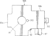
首先,将第一移动框51和固定基底53适当地定位在预定位置,并将它们暂时固定。如图23中所示,当将第一移动框51和固定基底53适暂时固定时,例如,将定位轴放进钻孔在第一移动框51的大致中心部分的定位孔311和钻孔在固定基底53的大致中心部分的定位孔312内。这时,直径大于定位轴的直径的脱离孔313钻孔在第二移动框52上以阻止定位轴与脱离孔313的内周表面接触。这样,第一移动框51和固定基底53之间的空间可以适当地定位在预定位置,结果校正透镜15的光轴可以相对于固定基底53适当地定位在预定位置。First, the first moving
这时,将圆柱形线圈91从横向放进该孔,并将轭66的下部件66b和下磁铁67b插进该孔。这时,将线圈支撑固定器85沿着第一方向X和第二方向Y适当地移动,并且测量由磁铁67a和67b的作用而获得的、并由固定在柔性印刷电路板87上的两个霍尔元件94和95检测到的磁通量密度。然后,将第一移动框51和固定基底53适当地定位在适当值的位置,其中将由两个霍尔元件94和95从磁铁67a和67b接收的磁力当作参考值。这种定位工作将在下面详细描述。At this time, the
在这种将第一移动框51和固定基底53适当地定位在预定位置的状态下,通过例如粘接剂的紧固机构将线圈支撑固定器85固定在固定基底53。以这种方式,完成图像稳定器5的组装工作并可以获得具有如图18-22中所示配置的图像稳定器5。可替换地,如下面所描述,可将线圈和两个霍尔元件固定在第一移动框上,使相对于该线圈和该两个霍尔元件相对移动的磁铁移动以检测由两个霍尔元件94和95接收的来自磁铁67a和67b的磁力,该磁铁可以基于检测结果适当地定位,然后,可通过粘接剂等将该磁铁固定在固定基底53上。In this state where the first moving
具有上述配置的图像稳定器5的动作如下。通过选择地或同时地将适当值的驱动电流穿过柔性印刷电路板87提供到传动装置54的平面线圈88和圆柱形线圈91来使图像稳定器5的校正透镜15移动。The
通过柔性加强板86将这种图像稳定器5的平面线圈88和圆柱形线圈91固定到线圈支撑固定器85,并且还通过线圈支撑固定器85将它们固定到固定基底53。这时,平面线圈88的推力产生部分89a和89b沿第二方向Y延伸,而圆柱形线圈91的推力产生部92沿第一方向X延伸。同样,由于固定在轭66的两个端部的两个磁铁67a和67b位于两个线圈88和91的上下方向内,由轭66和两个磁铁67a和67b形成的磁路的磁通量起作用以便垂直地通过平面线圈88的推力产生部分89a和89b和圆柱形线圈91的推力产生部分92。The
另一方面,将轭66和两个磁铁67a和67b固定在保持校正透镜15的第一移动框51上。通过具有第一移动框51的第一导轨将校正透镜15以其可以沿第一方向X移动的方式支撑到第二移动框52。此外,通过具有第二移动框52的第二导轨将校正透镜15以其可以沿第二方向Y移动的方式支撑到固定基底53。因此,由于第一导轨和第二导轨的作用,该校正透镜15可以沿第一方向X和第二方向Y的任何一个在预定范围内自由移动。On the other hand, the
现在,当电流流过平面线圈88时,由于平面线圈88的推力产生部分89a和89b沿第二方向Y延伸,所以该电流在推力产生部分89a和89b中流向第二方向Y。这时,由于磁路的磁通量作用于垂直于推力产生部分89a和89b的上下方向,根据弗莱明定律,定向于第一方向X的力作用于磁铁67a、67b和轭66。这样,固定有轭66等的第一移动框51沿第一方向X移动。因此,安装在第一移动框51上的校正透镜15由第一导轨引导并响应流过平面线圈88的电流量沿第一方向Y移动。Now, when current flows through the
另一方面,当电流流过圆柱形线圈91时,由于圆柱形线圈91的推力产生部分92沿第一方向X延伸,所以,电流在推力产生部分92中流向第一方向X。这时,由于磁路的磁通量作用于垂直于推力产生部分92的上下方向,根据弗莱明定律,定向于第二方向Y的力作用于磁铁67a、67b和轭66。因此,第二移动框52沿第二方向Y移动通过固定有轭66等的第一移动框51。结果,当第二移动框52与第一移动框51一起沿第二方向Y被导引和移动时,校正透镜15响应于流过圆柱形线圈91的电流量而沿第二方向Y移动。On the other hand, when the current flows through the
同样,当电流同时流过平面线圈88和圆柱形线圈91时,以复合方式执行通过上述平面线圈88完成的移动操作和通过圆柱形线圈91完成的移动操作。更特别地,在同一时间,校正透镜15在流向平面线圈88的电流的作用下沿第一方向Y移动,在流向圆柱形线圈91的电流的作用下沿第二方向Y移动。因此,校正透镜15变得可以沿倾斜方向移动以稳定透镜系统2的模糊图像。Also, when current flows through the
具有上述配置和作用的图像稳定器5安装在如图1-11中所示的透镜装置上。将该图像稳定器5插入并移出横向钻孔于透镜的透镜筒3的下镜筒18上的开口部分48,并将该图像稳定器5可拆卸地安装在下镜筒18上。在这种情况下,由于将本发明实施例的图像稳定器5配置成单一装置单元,所以其可以非常简单和快速地安装到下透镜筒18和从下透镜筒18拆除。图11等中的附图标记98表示覆盖该图像稳定器5的覆盖元件。该覆盖元件98通过例如固定螺钉的紧固机构可拆卸地安装在透镜的透镜筒3的下镜筒18上。The
接着,将参考附图12描述安装有图像稳定器5的透镜装置1的透镜系统2的操作。如图12中所示,当透镜装置1的物镜7A朝向物体定向时,从物体发出的光从物镜7A输入透镜系统2。这时,通过物镜7A的光由棱镜7B折射90度,此后,其沿着透镜系统2的光轴L向CCD4移动。特别地,在已经被棱镜7B反射之后,通过第一组透镜7的第二透镜7C的光通过第二组透镜8,第三组透镜9,第四组透镜10,第五组透镜11的第七透镜11A和校正透镜15到达滤光器14,通过该滤光器14将相应于物体的图像聚焦到CCD4的聚焦屏上。Next, the operation of the
在这种情况下,当拍照时,如果由于照相机的抖动透镜装置1既不摇晃也不振动,那么从物体发出的光如图12中实线所示的光6A那样沿着透镜装置1的的光轴L穿过第一组透镜的中央部分移动到第五组透镜,使得图像可以聚焦在CCD4的聚焦屏上的预定位置,从而可以获得不模糊的漂亮图像。In this case, when taking a picture, if the
另一方面,当拍照时,如果由于照相机抖动透镜装置1摇晃或振动,那么从物体发出的光在如图12中点划线所示的光6B或虚线所示的光6C那样倾斜的状态输入到第一组透镜内。虽然,这样的入射光6B和6C以从透镜装置1的光轴L偏移的状态分别地通过第一组透镜到第五组透镜,但是,可以通过响应于相机抖动等使校正透镜15移动预定的量来校正模糊图像。结果,图像可以聚焦到CCD4的聚焦屏上的预定位置,因此,可以通过消除模糊图像来获得漂亮的图像。On the other hand, when taking a picture, if the
照相机抖动、这种透镜装置1的振动等可由手抖动检测器检测到。例如,陀螺仪传感器可用做这种手抖动检测器。该陀螺仪传感器与透镜装置1一起安装在照相机本体上以检测由摄影师的手抖动、移动、振动等产生的作用于透镜装置1的加速度,角速度,角加速度等。将由陀螺仪检测到的例如加速度和角速度等信息提供给控制装置以便用这样的方式驱动处于该控制装置控制下的传动装置54,即根据在第一方向X上的移动和振动使第一移动框51沿第一方向X移动、根据在第二方向Y上的移动和振动使第二移动框52沿第二方向Y移动,从而将图像形成在CCD4的聚焦屏的预定位置。Camera shake, vibration of such a
图13至17是示出数字照相机100的图,该数字照相机100示出了装备有具有前述配置的透镜装置1的成像器装置的第一实施例。该数字照相机100利用半导体记录介质作为信息记录介质,而且可以由CCD(固态成像器)将来自物体的光学图像转换成电信号,并将这种电信号记录到半导体记录介质上或将这种电信号作为图像显示到例如液晶显示器等的显示装置上。13 to 17 are diagrams showing a
如图13等所示,这种数字照相机100包括照相机本体101,用于接收光形式的物体图像并将光导入作为成像器的CCD4的透镜装置1,由液晶显示器等形成的以基于CCD4输出的视频信号显示图像的显示装置102,用于控制透镜装置1的操作、液晶显示器102等的显示操作的控制装置103以及电池电源(未示出)等。As shown in FIG. 13 and the like, such a
该照相机本体101由长方形平面外壳形成并包括分别沿前后方向彼此设置的前盖105和后盖106,用于隔开由前后方向的前盖105和后盖106形成的空间部分的主框架107,安装在前盖105的前面以便在上下方向可滑动的透镜盖108等。在CCD 4设置为光轴L沿该上下方向取向的状态下,该透镜装置1固定在主框架107前面的一侧部分。此外,将控制装置103、闪光装置110等接合到主框架107上,该控制装置103通过将预定的微型计算机、电阻器、电容器和其他电子部件安装在印刷电路板上形成。The
控制装置103与透镜装置1并置,而闪光装置110位于控制装置103和透镜装置1上方。该闪光装置110包括暴露于前盖105前面的发光部分110a,用于驱动发光部分110a的驱动单元110b,用于提供预定电功率到驱动单元110b的电容器110c等。透镜装配孔111a和闪光装配孔111b钻孔于前盖105的相应位置以使闪光装置110的发光部分110a和透镜装置1的物镜7A露出。物镜7A与安装板21一起装配在透镜装配孔111a中,而发光部分110a装配在闪光装配孔111b中。The
此外,前盖105具有多个开孔111c,而多个设置在透镜盖108上的立柱(leg piece)插入所述多个开孔111c中。通过设置在多个立柱上的保持部分可以阻止透镜盖108从前盖105上的不经意脱落。通过多个开孔111c可以使得该透镜盖108沿上下方向移动,并且通过锁定机构(未示出)也可以将透镜盖108锁定在上端部和下端部。如图14中所示,当透镜盖108位于上端部时,物镜7A完全关闭,从而可以保护物镜7A。另一方面,如图15中所示,当透镜盖108移动到下端部时,物镜7A完全打开且电源开关接通,所以摄影变成可能。In addition, the
如图13和16中所示,后盖106包括正方形开孔窗112以露出显示装置102的显示屏。通过大尺度地打开后盖106的背面设置该开口窗112,并且显示装置102位于开口窗112的内部。显示设备102由具有相应于开口窗112的尺寸的液晶显示器和紧密地设置在该液晶显示器的内表面上的背光灯的组合组成。保护板114通过密封框113设置于显示装置102上其液晶显示器的一侧,并且保护板114的外边缘部分与开口窗112的内表面接触。As shown in FIGS. 13 and 16 , the
此外,后盖106具有多种操作开关。将用于选择功能模式(静止图像,移动图像,重放,等等)的模式选择开关115、用于执行变焦操作的变焦按钮116、用于显示屏幕的屏幕显示按钮117、用于选择多种菜单的菜单按钮118,用于移动指针来选择菜单等的方向键119、用于转换画面尺寸和删除画面的画面按钮121等作为操作开关设置在后盖106的适当位置。将扬声器孔122钻孔于后盖106的显示装置102的侧面的端部,并且将扬声器收容在该扬声器孔122中。腕带支持金属配件123安装在后盖106的相对侧的端部。In addition, the
同样,如图17等所示,该照相机本体101在其上表面提供有用于接通和关闭电源的电源按钮125,用于开始和停止摄影的摄影按钮126,当由于照相机的抖动而引起的照相机本体的移动和振动时用于通过操作图像稳定器5来执行模糊图像校正的照相机抖动设置按钮127。此外,麦克风孔128钻孔于照相机本体101的上表面的大致中心位置,并且将麦克风收容于该麦克风孔128中。将这些电源按钮125、摄影按钮126和照相机抖动设置按钮127安装于开关支架124上,该开关支架124安装在照相机本体101上。此外,麦克风孔128也钻孔于开关支架124上,并且将内置式麦克风固定到该开关支架124。Also, as shown in FIG. 17 and the like, the
图31是用于说明控制上述图像稳定器5的原理的方框图。如图31中所示,控制单元130包括图像稳定计算单元131,模拟伺服单元132,驱动电路单元133,四个放大器(AMP)134A、134B、135A和135B等。通过第一放大器(AMP)134A将第一陀螺仪传感器135连接到图像稳定计算单元131,并且通过第二放大器(AMP)134B将第二陀螺仪传感器136连接到图像稳定计算单元135。FIG. 31 is a block diagram for explaining the principle of controlling the
使第一陀螺仪传感器135适应于检测由于照相机抖动或手抖动等而使照相机本体101沿第一方向X偏移的量。使第二陀螺仪传感器136适应于检测由于照相机抖动或手抖动等而使照相机本体101沿第二方向Y偏移的量。虽然在本发明的上述实施例中提供两个陀螺仪135和136以分别检测照相机本体101沿第一方向X偏移的量和沿第二方向Y偏移的量,但是,本发明并不局限于此,并且不必说的是可以提供单一陀螺仪传感器来检测照相机本体沿两个方向(即第一方向X和第二方向Y)偏移的量。The
模拟伺服单元132连接到图像稳定计算单元131。模拟伺服单元132将由图像稳定计算单元131计算得到的数字形式的值转换成模拟值并输出与所获得的模拟值相应的控制信号。驱动电路单元133连接到模拟伺服单元132。第一霍尔元件94(即第一位置检测单元)通过第三放大器(AMP)135A连接到驱动电路单元133,而第二霍尔元件95(即第二位置检测单元)通过第四放大器(AMP)135B连接到驱动电路单元133。此外,平面线圈88(第一方向驱动线圈)连接到驱动电路单元133且圆柱形线圈91(第二方向驱动线圈)同样连接到驱动电路单元133。The
通过第一霍尔元件94检测第一移动框51沿第一方向X偏移的量,并通过第三放大器135A将其输入到驱动电路单元133。同样,通过第二霍尔元件95检测第二移动框52沿第二方向Y偏移的量,并通过第四放大器135B将其输入到驱动电路单元133。为了基于这些输入信号和从模拟伺服单元132来的控制信号来移动校正透镜15以校正模糊图像,驱动电路单元133输出预定控制信号到平面线圈88和圆柱形线圈91或者它们中的任意一个。The amount of displacement of the first moving
图32是示出包括具有上述配置和作用的图像稳定器5的数字照相机100的示意性配置的第一实施例的框图。如图32中所示,该数字照相机100包括具有图像稳定器5的透镜装置1,在控制装置中起重要角色的控制单元140,包括用于驱动控制单元140的程序存储器、数据存储器、其他RAM(随机存储器)、ROM(只读存储器)等的存储器装置141。该照相机100还包括用于输入各种指令信号以打开或关闭电源、选择摄影模式或拍照的操作单元120,显示拍摄的图像等的显示装置102,扩大存储容量的外部存储器143等等。FIG. 32 is a block diagram showing a first embodiment of a schematic configuration of a
该控制单元140由包括例如微型计算机(CPU)等的运算电路构成。该控制单元140与存储器装置141,操作单元142,模拟信号处理单元144,数字信号处理单元145,两个A/D(模拟-数字)转换器146、147,一个D/A(数字-模拟)转换器148和定时发生器(TG)149相连接。模拟信号处理单元144连接到安装在透镜装置1上的CCD4并基于与从CCD4输出的拍摄图像相应的模拟信号来执行预定信号处理。该模拟信号处理单元144连接到第一A/D转换器146,并且通过A/D转换器146将该模拟信号处理单元144的输出转换成数字信号。The
数字信号处理单元145连接到第一A/D转换器146,并且该数字信号处理单元145通过利用第一A/D转换器146提供的数字信号来执行预定的信号处理。显示装置102和外部存储器143连接到数字信号处理单元145,从而基于是从数字信号处理单元145输出的信号的数字信号在显示装置102上显示相应于物体的图像或将该图像存储到外部存储器143中。作为手抖动或照相机抖动检测单元的特殊例子示出的陀螺仪传感器151连接到第二A/D转换器147。该陀螺仪传感器151检测照相机本体101的移动、振动等并且可以根据检测结果来校正模糊图像。The digital
驱动控制单元152连接到D/A转换器148,该驱动控制单元152是用于图像稳定的伺服计算单元。驱动控制单元152可以通过响应校正透镜5所处的位置来驱动和控制图像稳定器5以校正模糊图像。图像稳定器5,用于通过检测两个移动框51和52的位置来检测校正透镜15的位置的位置检测单元的第一位置检测器(第一霍尔元件)94与第二位置检测器(第二霍尔元件)95连接到驱动控制单元152。定时发生器(TG)149连接到CCD4。Connected to the D/
因此,当将物体的图像输入透镜装置1的透镜系统2中并将其聚焦到CCD4的聚焦屏上时,将聚焦图像的图像信号作为模拟信号输出并将其提供给模拟信号处理单元144,在模拟信号处理单元144中,以预定的处理方式处理所述模拟信号然后通过第一A/D转换器146将处理的模拟信号转换成数字信号。通过数字信号处理单元145以预定的处理方式处理来自第一A/D转换器146的输出,从而将其作为相应于物体的图像显示在显示装置102上或将其作为存储信息存储在外部存储器143中。Therefore, when an image of an object is input into the
在这种摄影状态下,如果图像稳定器5处于可操作状态,那么当照相机本体101移动或振动时,陀螺仪传感器151检测到这种移动和振动并输出检测信号到控制单元140。控制单元140根据提供到其上的检测信号来执行预定计算处理并输出控制信号到驱动控制单元152以控制图像稳定器5的操作。驱动控制单元152基于从控制单元140来的控制信号输出预定驱动信号到图像稳定器5,从而使第一移动框51沿第一方向X移动预定量,并使第二移动框52沿第二方向Y移动预定量。结果,可以通过校正透镜15的移动来消除模糊图像并由此可以获得漂亮的图像。In this photographing state, if the
图33是示出包括具有上述配置和作用的图像稳定器5的数字照相机的示意性配置的第二实施例的框图。如图33中所示,该数字照相机100A包括具有图像稳定器5的透镜装置1,在控制装置中起重要作用的视频记录/再现电路单元160,包括程序存储器、数据存储器和其他RAM及ROM以驱动视频记录/再现电路单元160的内置存储器161,用于将拍摄图像等处理为预定信号的视频信号处理单元162,用于显示拍摄的图像等的显示装置163。该照相机100A还包括用于增加存储容量的外部存储器164,用于驱动和控制图像稳定器5的校正透镜控制单元165等。FIG. 33 is a block diagram showing a second embodiment of a schematic configuration of a digital camera including the
视频记录/再现电路单元160包括具有微型计算机(CPU)等的计算电路。内置存储器161,视频信号处理单元162,校正透镜控制单元165,监测驱动单元166,放大器167和三个接口(I/F)171、172及173连接到该视频记录/再现电路单元160。视频信号处理单元162通过放大器167连接到安装在透镜装置1的CCD 4,从而将处理为预定视频信号的信号输入到视频记录/再现电路单元160。The video recording/reproducing
显示装置163通过监测驱动单元166连接到视频记录/再现电路单元160。同样,连接器168连接到第一接口(I/F)171且外部存储器164可以可拆卸地连接到该连接器168。设置在照相机本体101上的连接终端174连接到第二接口(I/F)172。The
加速度传感器175通过第三接口(I/F)173连接到校正透镜控制单元165,该加速度传感器175是手抖动和照相机抖动检测单元。该加速度传感器175适于检测随着加速度来自移动和振动而加到照相机本体101上的位移,且陀螺仪传感器可用于所述加速度传感器175。驱动和控制校正透镜15的图像稳定器5的透镜驱动单元连接到校正透镜控制单元165并且两个用于检测校正透镜15位置的位置检测传感器94和95同样接到校正透镜控制单元165。An
因此,当将物体的图像输入透镜装置1的透镜系统2中并将图像聚焦到CCD4的聚焦屏上时,将聚焦图像的图像信号通过放大器167输入视频信号处理单元162。将由视频信号处理单元162处理为预定视频信号的信号输入视频记录/再现电路单元160。因此,相应于物体图像的信号从视频记录/再现电路单元160输出到监测驱动单元166和内置存储器161或外部存储器164。结果,相应于物体图像的图像通过监测驱动单元166显示在显示装置163上,或者如果有必要将其作为信息信号记录在内置存储器161或外部存储器164上。Therefore, when an image of an object is input into the
在这种摄影状态下,如果图像稳定器5处于可操作状态,那么当照相机本体101移动或振动时,加速度传感器175检测照相机本体101的移动或振动并通过校正透镜控制单元165将检测信号输出到视频记录/再现电路单元160。视频记录/再现电路单元160根据提供到其上的检测信号来执行预定计算处理并输出控制信号到校正透镜控制单元165以控制图像稳定器5的操作。校正透镜控制单元165基于从视频记录/再现电路单元160来的控制信号输出预定驱动信号到图像稳定器5,从而使第一移动框51沿第一方向X移动预定量,并使第二移动框52沿第二方向Y移动预定量。结果,可以通过校正透镜15的移动来消除模糊图像并由此可以获得极好的图像。In this photographing state, if the
图28是示出上述传动装置54的其他实施例的视图。传动装置54A通过改变线圈组件主体93的组装方向而构成,并且传动装置54A的组件类似于上述实施例中的组件。在这一实施例中,线圈组件主体93以下述方式安装在固定基底53上,即平面线圈88的纵向(推力产生部分延伸的方向)定位于第一方向X。然后,将轭66的纵向(这种关系也适应于磁铁67a和67b)设置成与平面线圈88的纵向一致并将其上固定有磁铁67a和67b的轭66安装在第一移动框51上。因此,圆柱形线圈91的推力产生部份沿垂直于第一方向X的第二方向Y延伸。FIG. 28 is a view showing another embodiment of the
在该实施例的情况下,当电流流到平面线圈88时,将产生可使第二移动框52沿第二方向Y移动的力。同样,当电源流到圆柱形线圈91时,将产生可使第一移动框51沿第一方向X移动的力。In the case of this embodiment, when current flows to the
图29和30是示出前述线圈组件主体93的其他实施例的图。该实施例中所示的线圈组件主体181利用平面线圈182作为供第一驱动器使用的线圈并且其也利用平面线圈183作为供第二驱动器使用的线圈。两个平面线圈182和183形成相同尺寸的椭圆形线圈。线圈组件主体181以这种方式构成,即将上平面线圈182安装在柔性印刷电路板184的一个表面上,将下平面线圈183固定在柔性印刷电路板184的另一个表面上。上平面线圈182和下平面线圈183以这种方式定位,即它们的纵向彼此垂直交叉。29 and 30 are diagrams showing other embodiments of the aforementioned coil component
此外,在该实施例中,将一个磁铁186安装在U形轭185的上部件上,从而构成磁路。磁铁186的纵向设置成垂直于上平面线圈182的推力产生部分的方向。具有上面配置的线圈组件主体181也能够实现与上述那些实施例类似的效果。特别是,在该实施例的情况中,由于线圈组件主体181可以做成比上述线圈组件主体93薄的多,所以其可以减少整个装置的厚度。Furthermore, in this embodiment, a
接着,将参考附图34-45描述通过检测磁铁67a和67b的磁力来检测校正透镜15的位置的两个霍尔元件94和95与磁铁67a和67b之间的关系。在图34-45中,与图1-33中相同的元件和部分用相同(或相似)的附图标记表示。Next, the relationship between the two
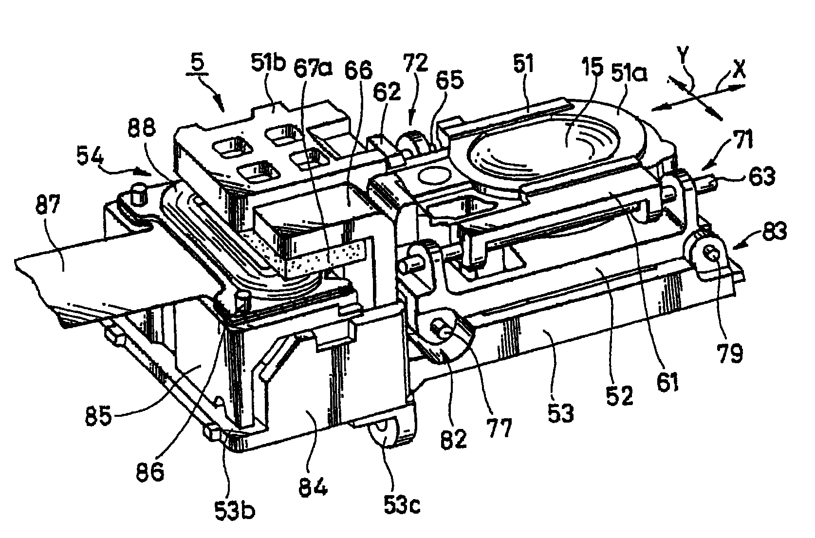
图34-37示出将本发明应用于包括移动磁铁系统驱动器的图像稳定器300的实施例。同样,图38-41示出将本发明应用于包括移动线圈(移动霍尔元件)系统驱动器的图像稳定器301的另一实施例。图42A-42D是用于说明磁铁67a和67b,轭66和两个霍尔元件(位置检测器)94及95等之间位置关系的图。图43A、43B、44A、44B、45和46是用于说明当将轭66设置有凸出部分或当将轭66没设置凸出部分时由霍尔元件95获得的磁通密度检测值的差异的视图。34-37 illustrate an embodiment of the invention applied to an
如图34-37中所示,图像稳定器300由第一移动框51A、第二移动框52A和固定基底53A组成。第一移动框51A包括环形透镜固定部分51a和与环形透镜固定部分51a整体形成为一体的轭固定部分51b。校正透镜15安装并固定在钻孔于透镜固定部分51a的中心部分的安装孔58a。第一主轴承部分61设置在透镜固定部分51a的一侧,且第一次轴承部分62设置在与上述一侧相反的另一侧。As shown in FIGS. 34-37, the
第一主导引轴63沿水平方向贯穿第一主轴承部分61并且该第一主导引轴63通过压配合固定在第一主轴承61的中间部分。此外,定位孔311钻孔于第一主轴承部分61上,沿横向开口的轴承槽64形成在第一次轴承部分62,第一次导引轴65与轴承槽64可滑动地啮合。The first
U形轭66整体固定在轭固定部分51b上。在相对的两部件66a和66b定向于上下方向的状态下,通过将结合两部件66a和66b的连接件66c固定到轭固定部分51b,轭66连接到轭固定部分51b。轭66的上部件66a和下部件66b是矩形的,且具有大致相同平面形状的平的正方形磁铁67a和67b通过例如粘接剂的固定机构整体固定到相应的上下部件66a和66b的内表面。A
凸出部分321、322和323、324设置在上部件66a和下部件66b的末梢边缘和一侧边缘以主动地释放磁铁67a和67b的磁力到轭66一侧。虽然这四个凸出部分321、322和323、324在本实施例中是半圆形的,但是,本发明并不限于此,它们可以是正方形、矩形、椭圆形、三角形和其他形状。在磁铁67a和67b彼此垂直的方向展开的两个平面与这些凸出部分321、322和323、324的内表面接触或者接近。Protruding
形成在上部件66a和下部件66b的末梢侧的第一凸出部分321和323适于释放在磁铁67a和67b末梢侧产生的磁力。同样,形成在上部件66a和下部件66b的侧面边缘侧的第二凸出部分322和324适于释放在磁铁67a和67b的侧面边缘侧产生的磁力。检测第一方向X的位置的第一霍尔元件94以非接触的状态设置在第一凸出部分321和323之间。然后,检测第二方向Y的位置的第二霍尔元件95以非接触的状态设置在第二凸出部分322和324之间。The first protruding
第二移动框52A形成为平面形状C形框本体形状的框本体。由两个轴承件71a和71b形成的的第二主轴承部分71设置在第二移动框52A的开口侧。固定在第一移动框51A上的第一主导引轴63的两个端部的凸出部分可滑动地插入两个轴承件71a和71b中,因此可转动地支撑在那里。同样,第一次导引轴65在其与第二主轴承部分71相反的一侧被第二移动框52A支撑。在该实施例中,将第一次导引轴65延伸的方向设置成第二方向Y,并将第三主轴承部分75沿平行于上述方向的方向设置在第二移动框52A的一侧。将第三主轴承部分75设置在第二移动框52A的一侧,而将第三次轴承部分76设置在第二移动框52A的另一侧。The second moving
第二主导引轴77贯穿第三主轴承部分75,且通过压配合将第三主轴承部分75固定在第二主导引轴77的中央部分。将横向开口的轴承槽78设置在第三次轴承部分76上,且第二次导引轴79与轴承槽78可滑动地啮合。The second
固定基底53A形成大致是具有设置在环形中央部分的四个部分处的凸出部分的十字形固定基底形状,且其包括移动框支撑部分53a和与移动框支撑部分53a整体形成一体的线圈支撑部分53b。由两个轴承件82a和82b形成的第四主轴承部分82设置在固定基底53A的一个侧边缘部分,且由两个轴承件83a和83b形成的第四次轴承部分83设置在与固定基底53A的一侧边缘部分相反的另一侧。第二移动框52A的第二主轴承导引轴77的两端的凸出部分可滑动地插入第四主轴承部分82的两个轴承件82a和82b,并因此可转动地支撑在那里。同样,第二次导引轴79的两个末端部分固定在第四次轴承部分83的两个轴承件83a和83b,因此可支撑在两个末端。此外,可以适当地定位固定基底53A和第一移动框51A的定位孔312钻孔在固定基底53A上。The fixed
在该实施例中,将第四主轴承部分82和第四次轴承部分83彼此相对的方向设置成第二方向Y。两个霍尔元件94及95和驱动线圈(未示出)设置在垂直于该第二方向Y的方向的一侧。将在上表面和横向开口的凹槽压痕部分330设置在固定基底53A一侧的线圈支撑部分53b上,两个霍尔元件94及95和驱动线圈(未示出)设置在该固定基底53A上。柔性印刷电路板87固定地支撑在包围该凹槽压痕部分330的右侧和左侧边缘部分,且两个霍尔元件94及95和驱动线圈(未示出)固定在柔性印刷电路板87的预定部分。In this embodiment, the direction in which the fourth
在第一移动框51A和固定基底53A适当地固定在预定位置的状态下,两个霍尔元件94和95以这种方式定位,即两个霍尔元件94和95的检测部分的中央可以与形成磁铁67a和67b的基准位置的两个平面的边缘部分重叠。也就是说,第一霍尔元件94以这种方式定位,即其中央部分可横过磁铁67a和67b的末梢端侧的边缘部分。然后,第二霍尔元件95以这种方式定位,即其中央部分可横过磁铁67a和67b的一侧边缘侧的边缘部分。In a state where the first moving
通过将基准针(未示出)插入定位孔311和312,可以简单地和确定地使第一移动框51A和固定基底53A定位,因此,可暂时固定第一移动框51A和固定基底53A。By inserting reference pins (not shown) into the positioning holes 311 and 312, the first
如图38-41中所示,图像稳定器301不同于上述实施例中所示的图像稳定器300,其中图像稳定器300的磁铁67a和67b与两个霍尔元件94和95彼此替换以此将驱动器构成为移动霍尔元件(移动线圈)系统驱动器。在图像稳定器301中,与图像稳定器300相同的元件和部分由相同的附图标记表示,因此没有必要描述。As shown in FIGS. 38-41 , the
图像稳定器301包括第一移动框51B、第二移动框52A和固定基底53B。第一移动框51B包括环形透镜固定部分51a和与透镜固定部分51a整体形成一体的线圈固定部分51c。两个霍尔元件94和95及线圈(未示出)固定在线圈固定部分51c。两个霍尔元件94和95及线圈(未示出)安装在柔性印刷电路板87上,且它们通过柔性印刷电路板87固定在线圈固定部分51c上。第二移动框52A的配置与上述实施例的配置类似。The
当固定基底53B具有大致与上述固定基底53A类似的外观形状时,由于柔性印刷电路板87沿横向凸出,所以固定基底53B的凹槽压痕部分331在形状上稍微不同。特别地,除了在上方和前方之外,固定基底53B的凹槽压痕部分331也沿横向开口,且轭66安置在该凹槽压痕部分331中。轭66在形状和结构上没有变化,但是,不同的是其安装方向在横向改变90度。While the fixed
轭66具有四个凸出部分321、322和323、324。设置在一侧边缘的两个凸出部分321和323供第一霍尔元件94使用以检测第一方向X,设置在末梢端的两个凸出部分322和324供第二霍尔元件95使用以检测第二方向Y。其他的配置与图34-37中所示的实施例相似。The
图42A-42D是用于说明两个霍尔元件94和95与磁铁67a、67b(或轭66)之间的关系的视图。特别地,图42A和42B是用于说明轭66的凸出部分322、324与霍尔元件95的移动方向之间关系的视图。轭66的上部件66a和下部件66b具有形成在它们的与上下方向相对的位置的凸出部分322和324。将是每个凸出部分322和324的底部侧的中央部分的上部件66a的边缘部分的中央部分(这种关系也适用于下部件66b)设置成基准点O2。通过以将第二霍尔元件95的检测部分的中央部分面向该基准点O2的方式调整位置,使第二霍尔元件95相对于磁铁67a和67b适当定位。42A-42D are views for explaining the relationship between the two
另一方面,在图42所示的实施例中,第一霍尔元件94具有其中无需设置凸出部分的配置,该配置将在稍后详细描述。如图42C和42D中所示,第一霍尔元件94定位成这种方式,即磁铁67a和67b的垂直于由第二霍尔元件95检测的边缘部分的一边缘部分可横过第一霍尔元件94的中央部分。第一霍尔元件94和第二霍尔元件95以不同方式应用的原因将在下面描述。On the other hand, in the embodiment shown in FIG. 42 , the
图45示出的是由霍尔元件94和95所接收的来自磁铁67a和67b的磁力强度根据霍尔元件94和95的位置而改变的方式的图示,所述磁力强度沿截面方向通过磁铁67a和67b。根据霍尔元件94和95的位置而改变的由霍尔元件94和95接收的磁通密度如图45中的实线R所示。磁通密度在磁铁67a和67b的中央部分保持高位值并相对缓慢地改变,并且其在从边缘部分前面的少许部分到边缘部分后面的少许部分的范围内大致成线性地(按比例地)改变。然后,当霍尔元件94和95显著地从磁铁67a和67b偏移时,磁通密度的改变又变得缓慢并减少至零。FIG. 45 shows a graphical representation of the manner in which the strength of the magnetic force received by the
如图45中所示,当通过微分实线R计算倾角时,由霍尔元件94和95接收的磁通量变成如实线R’所示的曲线并且其传染点(infection point)与磁铁67a和67b的边缘大致彼此重叠。因此,在实线R由霍尔元件94和95测量之后,当实线R’通过对测量值进行微分来计算时,相对于磁铁67a和67b的边缘,第一霍尔元件94可适当地定位在第一基准点O1而第二霍尔元件95可适当地定位在第二基准点O2。As shown in FIG. 45, when the inclination angle is calculated by differentiating the solid line R, the magnetic flux received by the
将描述适当定位霍尔元件94和95的例子。首先,当第一移动框51和固定基底53适当定位时,通过将基准针(未示出)插入它们的定位孔311和312来暂时地固定第一移动框51和固定基底53。接着,在将校正透镜15的光轴设置成与透镜系统2的光轴L一致的状态下,将磁铁67a和67b(或第一霍尔元件94)以这样的方式移动,即可沿第一方向X相对地移动第一霍尔元件94,并且可以通过测量上述实线R来检测第一基准点O1。相似地,在将校正透镜15的光轴设置成与透镜系统2的光轴L一致的状态下,将磁铁67a和67b(或第二霍尔元件95)以这样的方式移动,即可沿第二方向Y相对地移动第二霍尔元件95,并且可以通过测量上述实线R来检测第二基准点O2。An example of appropriately positioning the
通过同时沿第一方向X和第二方向Y相对地移动两个霍尔元件94和95,也就是说,通过在具有大约45度角的方向移动磁铁67a和67b(或霍尔元件94和95),可以减少测量时间。By relatively moving the two
由于相对移动的霍尔元件94和95与磁铁67a和67b具有图45中所示的关系,所以,如果例如把霍尔元件94和95的移动距离(可移动宽度)作为Q,当将从点P1到点P2的可移动宽度Q或将从点P3到点P4的可移动宽度Q用作检测宽度时,其磁通密度的变化Δ小(Δ小),所以变得难于精确检测磁通密度的变化。另一方面,当将从点P2到点P3的可移动宽度Q用作检测宽度时,磁通密度的变化Δ大(Δ大)且其变得可以精确检测磁通密度的变化。另外,磁通密度Δ大致线性地改变,因此,变得可以精密地和精确地控制位置。Since the relatively moving
本发明可应用这种特性。当磁铁67a和67b的边缘部分由霍尔元件94和95检测时可以完成对准,因此可以高精度检测位置。The present invention can apply this characteristic. Alignment can be accomplished when the edge portions of the
图46A-46C所示的是由霍尔元件94和95接收的从磁铁67a和67b来的磁力强度根据霍尔元件94和95的位置而改变的方式的图示,所述磁力平行地通过接近轭66的上部件66a和下部件66b边缘的部分。图46A所示的是当轭66不设置两个凸出部分322和324时由第二霍尔元件95接收的磁力强度。图46B所示的是当轭66设置两个凸出部分322和324时由第二霍尔元件95接收的磁力强度。图46C所示的是当第一霍尔元件94在轭66的长侧的一侧移动时,由第一霍尔元件94接收的来自磁铁67a和67b的磁力强度。46A-46C are illustrations of the way in which the strength of the magnetic force received by the
特别地,轭66设置两个凸出部分321和322(321到324)的原因如下。如图42C所示,在第一霍尔元件94的情况下,由于磁铁67a和67b的相对于第二方向Y(即第一霍尔元件94相对移动的方向)的边缘部分非常长,即使当第一霍尔元件94相对移动一定距离时,由第一霍尔元件94接收的从磁铁67a和67b来的磁力强度也不会改变很大。In particular, the reason why the
另一方面,在第二霍尔元件95的情况下,如果磁铁67a和67b的相对于第一方向X(即第二霍尔元件95相对移动的方向)的边缘部分短,此时,即使当第二霍尔元件95移动的非常少时,第二霍尔元件95也不可避免地接近磁铁67a和67b的边缘部分的端部。因此,如图46A中所示,当第二霍尔元件95接近磁铁67a和67b的边缘部分的端部时,从磁铁67a和67b来的磁力减少,所以由第二霍尔元件95接收的从磁铁67a和67b来的磁力强度改变。结果,即使当第二霍尔元件95沿第一方向X相对地移动时,输出也会好像第二霍尔元件95沿第二方向Y移动一样而改变,从而导致难于精确地检测位置。On the other hand, in the case of the
轭66设置有凸出部分321、322(321到324)以解决上述问题。由于轭66设置有凸出部分321到324,所以可以主动地释放磁通量到凸出部分321、322(321到324)。因此,如图46B中所示,接近磁铁67a和67b中心的磁通密度可能减少且检测在第一方向X的移动范围内沿第二方向Y的位置的第二霍尔元件95的输出可基本保持相同。结果,可以显著地减少第一霍尔元件94和第二霍尔元件95之间的互相干扰。The
图43A、43B和图44A、44B是示出在轭66设置有凸出部分321、322(321到324)或轭66没有设置有凸出部分321、322(321到324)的状态下,当测量霍尔元件的磁通密度时所获得的结果图,其导致图42C中所示的第二霍尔元件95的检测结果。同样,图43B和图44B是示出在轭66没有设置有凸出部分321、322(321到324)的状态下,当测量霍尔元件的磁通密度时所获得的结果图,其导致图42C中所示的第二霍尔元件95的检测结果。在每张图中,点0表示基准位置而点O2相应于第二霍尔元件95中的基准点。此时,在每个从各自基准点到第一方向X和第二方向Y移动0.2mm的位置处检测到的值表示在各自的表格和图表中。43A, 43B and FIGS. 44A, 44B are diagrams showing that when the
每个值的单位是高斯(G=10-4Wb/m2)。The unit of each value is Gauss (G=10 -4 Wb/m 2 ).
同样,磁通密度Δ的公式如下:Similarly, the formula for the magnetic flux density Δ is as follows:
磁通密度Δ=霍尔元件输出/移动距离Magnetic flux density Δ = Hall element output / moving distance
如上所述,根据本发明的图像稳定器、透镜装置和成像装置,由于通过移动霍尔元件或磁铁来检测霍尔元件的输出,霍尔元件和磁铁基于检测结果适当地定位且其通过粘接剂等固定,所以可以相对简单和高精确地适当定位霍尔元件和磁铁。因此,可以提高这种图像稳定器的生产率。同样,根据由本发明制造的图像稳定器,由于将由磁铁和轭形成的一组磁路元件用作用于第一驱动器的磁路并同样用作用于第二驱动器的磁路,所以可以减少部件的数量,使得图像稳定器本身的尺寸紧凑且重量轻。结果,使得其上安装有本发明的图像稳定器的透镜装置和包括该透镜装置的整个成像器装置的尺寸更紧凑且重量更轻。As described above, according to the image stabilizer, lens device, and imaging device of the present invention, since the output of the Hall element is detected by moving the Hall element or the magnet, the Hall element and the magnet are properly positioned based on the detection result and they are bonded by bonding. Fixing agent, etc., so that Hall elements and magnets can be properly positioned relatively easily and with high precision. Therefore, productivity of such an image stabilizer can be improved. Also, according to the image stabilizer manufactured by the present invention, since a set of magnetic circuit elements formed of a magnet and a yoke are used as a magnetic circuit for the first driver and also as a magnetic circuit for the second driver, the number of parts can be reduced , making the image stabilizer itself compact in size and light in weight. As a result, the lens device on which the image stabilizer of the present invention is mounted and the entire imager device including the lens device are made more compact in size and lighter in weight.
同样,由于将构成磁路元件的磁铁用作用于第一位置探测器(第一霍尔元件94)以检测第一导轨(第一移动框51)的位置的磁铁并同样用作用于第二位置探测器(第二霍尔元件95)以检测第二导轨(第二移动框52)的位置的磁铁,所以可以实现部件数量的更加减少。此外,由于第一和第二霍尔元件安装在同一基板上,可以减少放置第一和第二霍尔元件所需的空间,因此,图像稳定器的尺寸可以制得小得多。Also, since the magnet constituting the magnetic circuit element is used as a magnet for the first position detector (first Hall element 94) to detect the position of the first guide rail (first moving frame 51) and is also used as a magnet for the second position The detector (the second hall element 95) is a magnet for detecting the position of the second guide rail (the second moving frame 52), so that the number of parts can be further reduced. In addition, since the first and second Hall elements are mounted on the same substrate, the space required for placing the first and second Hall elements can be reduced, and therefore, the size of the image stabilizer can be made much smaller.
此外,由于包括两个线圈、用于提供电源到该两个线圈的柔性印刷电路板等的线圈组件主体固定在固定基底上,并且轭和磁铁固定在第一移动框上,所以由提供电流到线圈产生的推力可作用于轭和磁体侧,从而可以移动校正透镜。结果,可将连接到线圈组件主体的柔性印刷电路板固定到恒定位置且不用维持用来移动柔性印刷电路板所需的空间,所以可以使该装置小型化。另外,由于校正透镜不与柔性印刷电路板一致的移动,使校正透镜移动的推力的大小不需要达到足以使柔性印刷电路板弯曲那样大,因此,可以减少图像稳定器的功率消耗。In addition, since the coil assembly main body including the two coils, the flexible printed circuit board for supplying power to the two coils, etc. is fixed on the fixed base, and the yoke and the magnet are fixed on the first moving frame, by supplying current to the The thrust force generated by the coil acts on the yoke and magnet side to move the correction lens. As a result, the flexible printed circuit board connected to the coil assembly main body can be fixed to a constant position without maintaining a space required for moving the flexible printed circuit board, so the device can be miniaturized. In addition, since the correction lens does not move in conformity with the flexible printed circuit board, the magnitude of the thrust force for moving the corrected lens does not need to be large enough to bend the flexible printed circuit board, thus reducing the power consumption of the image stabilizer.
同样,由于透镜装置构成可拆卸的透镜系统,所以,通过物镜的光被棱镜弯曲90度并被导入图像稳定器的校正透镜(第五组透镜),当将成像器装置放置在正的高度(positive attitude)时,校正透镜变得与地面平行,所以第一方向和第二方向(即校正透镜的移动方向)与重力作用方向变得互相垂直。结果,由于用于固定校正透镜以便可以自由地移动校正透镜的第一和第二移动框从不会被重力沿第一和第二方向拉动,且第一和第二移动框被沿与重力方向相对的方向提升然后固定,所以没必要给图像稳定器持续地提供电力。结果,当摄影师在将成像装置放置在正的高度的状态下拍照时,可以显著地减少所需的功率消耗,因此,可以延长成像器装置在使用中的可操作时间。另外,由于可以减少移动校正透镜所需要的推力,所以第一和第二移动框的重量的容许量,即大约1G的照相机抖动加速度变成可能,因此,可以克服照相机本体的移动和振动,例如较大的照相机抖动。Also, since the lens assembly constitutes a detachable lens system, the light passing through the objective lens is bent by 90 degrees by the prism and directed to the correction lens (fifth lens group) of the image stabilizer, when the imager assembly is placed at a positive height ( positive attitude), the correction lens becomes parallel to the ground, so the first direction and the second direction (that is, the moving direction of the correction lens) and the direction of gravity become perpendicular to each other. As a result, since the first and second moving frames for fixing the correction lens so that the correction lens can be moved freely are never pulled by gravity in the first and second directions, and the first and second moving frames are pulled in the direction of gravity The relative orientation is raised and then fixed, so there is no need to continuously power the image stabilizer. As a result, when a photographer takes pictures in a state where the imaging device is placed at a positive height, power consumption required can be significantly reduced, and therefore, the operable time of the imager device in use can be extended. In addition, since the thrust required to move the correction lens can be reduced, the allowable amount of the weight of the first and second moving frames, that is, camera shake acceleration of about 1G becomes possible, and therefore, it is possible to overcome the movement and vibration of the camera body, such as Excessive camera shake.
根据本发明的例子,由于图像稳定器包括与用于检测第一方向位置的霍尔元件相对(该关系同样适应于第二方向)的后轭和用作凸出部分的凸面部分设置在相反轭的外缘的附近,从而主动地释放磁通量到凸出部分,所以可以减少磁铁中心附近的磁通密度。同样,用于检测在第二方向(该关系同样适应于第一方向)的移动范围内的第一方向位置的霍尔元件的输出可保持基本相同。因此,可以高精度地检测位置。According to the example of the present invention, since the image stabilizer includes the rear yoke opposite to the Hall element for detecting the position in the first direction (this relationship is also applicable to the second direction) and the convex portion serving as the convex portion is disposed on the opposite yoke Near the outer edge of the magnet, thereby actively releasing the magnetic flux to the protruding part, so the magnetic flux density near the center of the magnet can be reduced. Likewise, the output of the Hall element for detecting a position in the first direction within a range of movement in the second direction (the relationship also applies to the first direction) may remain substantially the same. Therefore, the position can be detected with high precision.
虽然,至此已经说明了上述实施例所示的图像稳定器5利用了其中固定有两组线圈88a、88b和线圈91的移动磁铁系统传动装置,制成可移动的磁铁67a、67b和轭66的例子,但是,本发明并不限于此。相反,不必说,上述移动磁铁型传动装置可以构造成移动线圈系统传动装置,其中磁铁67a、67b和轭66固定在固定基底53上,两组线圈88a、88b,线圈91,霍尔元件94、95,柔性印刷电路板87和柔性加强板86固定在固定基底53上,线圈等制成与校正透镜15一起可移动的。Although, it has been described so far that the
本发明并不局限于各附图中所示的上述实施例并且其可在不脱离本发明本质的前提下作出各种改变。例如,虽然至此已经描述了上述实施例中的将数字照相机应用于成像器装置的例子,但是,本发明并不限于此,而是可将其应用于数字摄像机,具有内置照相机的个人电脑,具有内置照相机的移动电话和其他成像器装置。此外,虽然至此已经描述了将五组透镜用作透镜装置1的例子,但是,没有必要说本发明可用于少于五组透镜的透镜或多于六组透镜的透镜。The present invention is not limited to the above-described embodiments shown in the drawings and various changes can be made thereto without departing from the essence of the invention. For example, although an example in which a digital camera is applied to an imager device in the above embodiments has been described so far, the present invention is not limited thereto but may be applied to a digital video camera, a personal computer with a built-in camera, a computer with Mobile phones and other imager devices with built-in cameras. Furthermore, although an example in which five lens groups are used as the
本领域技术人员可以理解的是,根据设计要求和其他因素可以存在各种改进、组合、次组合和改变,它们都在附加权利要求或其等同物的范围内。It would be understood by those skilled in the art that there may be various modifications, combinations, sub-combinations and changes depending on design requirements and other factors, which are all within the scope of the appended claims or the equivalents thereof.
Claims (7)
Applications Claiming Priority (2)
| Application Number | Priority Date | Filing Date | Title |
|---|---|---|---|
| JP2005201826A JP4792844B2 (en) | 2005-07-11 | 2005-07-11 | Image blur correction device, lens device, and imaging device |
| JP201826/05 | 2005-07-11 |
Publications (2)
| Publication Number | Publication Date |
|---|---|
| CN1896803A CN1896803A (en) | 2007-01-17 |
| CN100501503C true CN100501503C (en) | 2009-06-17 |
Family
ID=37074923
Family Applications (1)
| Application Number | Title | Priority Date | Filing Date |
|---|---|---|---|
| CNB200610093469XA Expired - Fee Related CN100501503C (en) | 2005-07-11 | 2006-06-05 | Image stabilizer, lens apparatus and imager apparatus |
Country Status (6)
| Country | Link |
|---|---|
| US (1) | US7650065B2 (en) |
| EP (1) | EP1744547A3 (en) |
| JP (1) | JP4792844B2 (en) |
| KR (1) | KR101231486B1 (en) |
| CN (1) | CN100501503C (en) |
| TW (1) | TW200708882A (en) |
Families Citing this family (37)
| Publication number | Priority date | Publication date | Assignee | Title |
|---|---|---|---|---|
| US7684685B2 (en) * | 2005-06-07 | 2010-03-23 | Sony Corporation | Image stabilizer, lens barrel and imager apparatus |
| JP4862411B2 (en) | 2006-01-30 | 2012-01-25 | ソニー株式会社 | Image blur correction device, lens device, and imaging device |
| JP4992478B2 (en) * | 2007-03-07 | 2012-08-08 | 株式会社ニコン | Camera shake correction unit, lens barrel, camera |
| JP4488041B2 (en) | 2007-08-02 | 2010-06-23 | ソニー株式会社 | Image blur correction apparatus and imaging apparatus |
| JP4962781B2 (en) * | 2007-08-13 | 2012-06-27 | コニカミノルタアドバンストレイヤー株式会社 | Position detection apparatus and electronic apparatus |
| KR101506479B1 (en) * | 2007-09-12 | 2015-03-30 | 삼성전자주식회사 | System and method for optical path correction by driving a bending prism composed of a refracting surface |
| KR101378332B1 (en) * | 2007-10-15 | 2014-03-27 | 삼성전자주식회사 | Shake correction module for photographing apparatus |
| JP4991497B2 (en) * | 2007-11-28 | 2012-08-01 | 三星電子株式会社 | Image blur correction device |
| KR101464533B1 (en) * | 2008-02-11 | 2014-11-24 | 삼성전자주식회사 | Camera shake compensation device |
| KR101398470B1 (en) * | 2008-02-12 | 2014-06-27 | 삼성전자주식회사 | Shake correction module for photographing apparatus and photographing apparatus having the same |
| KR101446777B1 (en) * | 2008-05-30 | 2014-10-01 | 삼성전자주식회사 | Image stabilizer and digital photographing apparatus comprising the same |
| TWI381242B (en) * | 2008-10-28 | 2013-01-01 | Asia Optical Co Inc | Adjustable anti - vibration image sensing module and its adjustment method |
| US8289400B2 (en) | 2009-06-05 | 2012-10-16 | Apple Inc. | Image capturing device having continuous image capture |
| US8624998B2 (en) * | 2009-06-05 | 2014-01-07 | Apple Inc. | Camera image selection based on detected device movement |
| JP5846346B2 (en) | 2009-08-21 | 2016-01-20 | ミツミ電機株式会社 | Camera shake correction device |
| JP5611578B2 (en) * | 2009-12-08 | 2014-10-22 | Hoya株式会社 | Optical element position control device |
| JP5675211B2 (en) * | 2010-08-18 | 2015-02-25 | キヤノン株式会社 | Optical device |
| JP5535139B2 (en) * | 2011-06-30 | 2014-07-02 | 株式会社ヴァレオジャパン | Proximity sensor |
| JP5821356B2 (en) | 2011-07-15 | 2015-11-24 | ミツミ電機株式会社 | Lens drive device |
| JP5849483B2 (en) | 2011-07-15 | 2016-01-27 | ミツミ電機株式会社 | Lens drive device |
| JP2013029643A (en) * | 2011-07-28 | 2013-02-07 | Hoya Corp | Imaging unit |
| JP2013114167A (en) * | 2011-11-30 | 2013-06-10 | Jvc Kenwood Corp | Imaging apparatus |
| JP5979878B2 (en) | 2012-01-06 | 2016-08-31 | キヤノン株式会社 | Vibration correction apparatus, lens barrel, and optical apparatus |
| KR102226299B1 (en) | 2012-02-14 | 2021-03-09 | 미쓰미덴기가부시기가이샤 | Lens Driving Device |
| KR102151763B1 (en) | 2013-06-03 | 2020-09-04 | 삼성전자주식회사 | Image stabilizer and digital photographing apparatus comprising the same |
| JP6297925B2 (en) * | 2014-05-29 | 2018-03-20 | 旭化成エレクトロニクス株式会社 | The camera module |
| JP6584209B2 (en) * | 2015-08-10 | 2019-10-02 | キヤノン株式会社 | Image blur correction device, lens barrel, and imaging device |
| CN105499159A (en) * | 2016-01-26 | 2016-04-20 | 安徽捷迅光电技术有限公司 | Calibration tool for laser head of color sorter |
| CN113448046B (en) * | 2016-04-28 | 2024-04-30 | Lg伊诺特有限公司 | Lens drive mechanism, camera module and optical device |
| JP6989275B2 (en) * | 2017-03-30 | 2022-01-05 | 日本電産サンキョー株式会社 | Optical unit with runout correction function |
| KR102473411B1 (en) | 2017-07-03 | 2022-12-02 | 삼성전기주식회사 | Camera module |
| WO2019065826A1 (en) | 2017-09-27 | 2019-04-04 | 富士フイルム株式会社 | Mobile assist device, image stabilization device, and imaging device |
| JP7393158B2 (en) * | 2019-09-05 | 2023-12-06 | ニデックインスツルメンツ株式会社 | Optical unit with shake correction function |
| CN110501797B (en) * | 2019-09-20 | 2022-09-06 | 合肥英睿系统技术有限公司 | Infrared lens device capable of automatically detecting and identifying view field |
| KR102872782B1 (en) * | 2020-09-16 | 2025-10-20 | 엘지이노텍 주식회사 | Camera module and optical apparatus |
| TWI768850B (en) * | 2021-04-27 | 2022-06-21 | 台灣立訊精密有限公司 | Image compensation device and prism supporting mechanism thereof |
| KR20250005716A (en) * | 2023-07-03 | 2025-01-10 | 엘지이노텍 주식회사 | Actuator and camera device including the same |
Family Cites Families (36)
| Publication number | Priority date | Publication date | Assignee | Title |
|---|---|---|---|---|
| JPS6185060A (en) * | 1984-09-29 | 1986-04-30 | Toshiba Corp | Noncontact positioning device |
| JPS62180215A (en) * | 1986-02-05 | 1987-08-07 | Hitachi Ltd | Adjusting device for incorporating magnetic sensor in magnetic encoder |
| JP2510759Y2 (en) * | 1987-05-11 | 1996-09-18 | アイシン精機株式会社 | Embroidery frame fixing device |
| US5266988A (en) * | 1989-12-18 | 1993-11-30 | Canon Kabushiki Kaisha | Image shake suppressing device for camera |
| JP2641172B2 (en) | 1989-12-18 | 1997-08-13 | キヤノン株式会社 | Image stabilizer |
| JP2720955B2 (en) | 1989-12-18 | 1998-03-04 | キヤノン株式会社 | Image blur prevention device |
| JP3186823B2 (en) | 1992-03-18 | 2001-07-11 | 積水化学工業株式会社 | Recording material for water-based ink |
| EP0662626B1 (en) | 1993-12-28 | 2000-10-04 | Canon Kabushiki Kaisha | Light deflection apparatus with angular deviation detection means |
| DE4414527C1 (en) | 1994-04-26 | 1995-08-31 | Orto Holding Ag | Electronically-commutated DC motor for vehicle propulsion drive |
| JPH0863769A (en) * | 1994-06-17 | 1996-03-08 | Sony Corp | Objective lens driving device and manufacturing method thereof |
| US5880455A (en) | 1995-08-08 | 1999-03-09 | Nikon Corporation | Focal position detection apparatus having a light reflecting member with plural reflecting films |
| JPH0980550A (en) | 1995-09-13 | 1997-03-28 | Nikon Corp | Image stabilizer |
| US5835799A (en) | 1996-07-10 | 1998-11-10 | Canon Kabushiki Kaisha | Image blur prevention apparatus |
| JP3513329B2 (en) * | 1996-07-10 | 2004-03-31 | キヤノン株式会社 | Image stabilization device |
| JP3417446B2 (en) | 1996-10-01 | 2003-06-16 | 富士写真光機株式会社 | Image stabilizer |
| JP3417447B2 (en) | 1996-10-01 | 2003-06-16 | 富士写真光機株式会社 | Image stabilizer |
| JPH10134382A (en) * | 1996-11-01 | 1998-05-22 | Nec Corp | Device for driving objective lens and method therefor |
| US5974269A (en) * | 1996-11-07 | 1999-10-26 | Canon Kabushiki Kaisha | Image blur preventing apparatus |
| US5995762A (en) | 1997-05-12 | 1999-11-30 | Asahi Kogaku Kogyo Kabushiki Kaisha | Lens driving mechanism |
| JP3754810B2 (en) * | 1997-09-19 | 2006-03-15 | キヤノン株式会社 | Correction optical system support device |
| JP3231688B2 (en) | 1997-12-02 | 2001-11-26 | 旭光学工業株式会社 | Camera shake correction mechanism of binocular device |
| JPH11194262A (en) | 1998-01-06 | 1999-07-21 | Asahi Optical Co Ltd | Observation optical instrument having image blur correction system |
| JP4181663B2 (en) * | 1998-06-30 | 2008-11-19 | キヤノン株式会社 | Correction optical device, image shake correction device, camera, and interchangeable lens |
| JP4114286B2 (en) * | 1998-08-14 | 2008-07-09 | ソニー株式会社 | Biaxial actuator, optical component thereof, and optical disk device |
| CN1205495C (en) * | 1999-01-26 | 2005-06-08 | 松下电器产业株式会社 | Lens barrel |
| JP2000258813A (en) | 1999-03-09 | 2000-09-22 | Matsushita Electric Ind Co Ltd | Image stabilization device |
| JP3339468B2 (en) | 1999-06-24 | 2002-10-28 | ミノルタ株式会社 | Printer-integrated digital camera |
| JP2001215543A (en) * | 2000-01-31 | 2001-08-10 | Canon Inc | Image stabilizer |
| JP2003057707A (en) * | 2001-08-08 | 2003-02-26 | Matsushita Electric Ind Co Ltd | Image stabilizer |
| JP4143318B2 (en) | 2002-03-29 | 2008-09-03 | キヤノン株式会社 | Lens barrel and optical apparatus using the same |
| JP2003316512A (en) * | 2002-04-24 | 2003-11-07 | Asahi Kasei Corp | pointing device |
| JP2003270695A (en) | 2003-02-13 | 2003-09-25 | Matsushita Electric Ind Co Ltd | Image stabilization device |
| JP2004295932A (en) * | 2003-03-25 | 2004-10-21 | Funai Electric Co Ltd | Objective lens driving device for optical head |
| JP2004364392A (en) | 2003-06-03 | 2004-12-24 | Canon Inc | Linear motor, stage apparatus including the same, exposure apparatus, and device manufacturing method |
| US7009321B1 (en) | 2004-10-04 | 2006-03-07 | L-3 Communications Sonoma Eo, Inc. | Compact two-axis wide gap torquer motor |
| US7684685B2 (en) | 2005-06-07 | 2010-03-23 | Sony Corporation | Image stabilizer, lens barrel and imager apparatus |
-
2005
- 2005-07-11 JP JP2005201826A patent/JP4792844B2/en not_active Expired - Fee Related
-
2006
- 2006-06-05 KR KR1020060050148A patent/KR101231486B1/en not_active Expired - Fee Related
- 2006-06-05 US US11/446,269 patent/US7650065B2/en not_active Expired - Fee Related
- 2006-06-05 EP EP06252903A patent/EP1744547A3/en not_active Withdrawn
- 2006-06-05 TW TW095119906A patent/TW200708882A/en not_active IP Right Cessation
- 2006-06-05 CN CNB200610093469XA patent/CN100501503C/en not_active Expired - Fee Related
Also Published As
| Publication number | Publication date |
|---|---|
| TWI318720B (en) | 2009-12-21 |
| US20070009244A1 (en) | 2007-01-11 |
| KR101231486B1 (en) | 2013-02-07 |
| KR20070007711A (en) | 2007-01-16 |
| EP1744547A2 (en) | 2007-01-17 |
| US7650065B2 (en) | 2010-01-19 |
| JP2007017874A (en) | 2007-01-25 |
| CN1896803A (en) | 2007-01-17 |
| EP1744547A3 (en) | 2009-12-02 |
| JP4792844B2 (en) | 2011-10-12 |
| TW200708882A (en) | 2007-03-01 |
Similar Documents
| Publication | Publication Date | Title |
|---|---|---|
| CN100501503C (en) | Image stabilizer, lens apparatus and imager apparatus | |
| JP4862303B2 (en) | Method for manufacturing image blur correction apparatus | |
| US7822331B2 (en) | Image blur correction device, lens barrel and imaging apparatus | |
| EP1862842B1 (en) | Image stabilizer, lens device and imaging apparatus | |
| CN1979254B (en) | Lens mounts and camera equipment | |
| US7684685B2 (en) | Image stabilizer, lens barrel and imager apparatus | |
| US20070133092A1 (en) | Lens device and imager apparatus | |
| JP2008191267A (en) | Image blur correction device, lens barrel, and imaging device | |
| JP2008134329A (en) | Image blur correction device, lens barrel, and imaging device | |
| JP4802871B2 (en) | Image blur correction device, lens device, and imaging device | |
| CN100570434C (en) | Image Stabilizer, Lens Barrel and Imaging Device | |
| JP4935308B2 (en) | Image blur correction device, lens barrel, and imaging device | |
| JP2007058090A (en) | Image blur correction device, lens device, and imaging device | |
| JP4770282B2 (en) | LENS DEVICE AND IMAGING DEVICE | |
| JP4479596B2 (en) | Image blur correction device, lens device, and imaging device | |
| JP2007011222A (en) | Image blur correction device, lens device, and imaging device | |
| JP2007058089A (en) | Image blur correction device, lens device, and imaging device | |
| JP2007033668A (en) | Image blur correction device, lens device, and imaging device | |
| JP2009210922A (en) | Image blur correction unit, lens barrel device, and imaging apparatus | |
| JP2008268756A (en) | Image blur correction device, lens device, and imaging device |
Legal Events
| Date | Code | Title | Description |
|---|---|---|---|
| C06 | Publication | ||
| PB01 | Publication | ||
| C10 | Entry into substantive examination | ||
| SE01 | Entry into force of request for substantive examination | ||
| C14 | Grant of patent or utility model | ||
| GR01 | Patent grant | ||
| CF01 | Termination of patent right due to non-payment of annual fee |
Granted publication date: 20090617 Termination date: 20150605 |
|
| EXPY | Termination of patent right or utility model |