CN100498570C - Image forming apparatus and its control method - Google Patents
Image forming apparatus and its control method Download PDFInfo
- Publication number
- CN100498570C CN100498570C CNB2005101277277A CN200510127727A CN100498570C CN 100498570 C CN100498570 C CN 100498570C CN B2005101277277 A CNB2005101277277 A CN B2005101277277A CN 200510127727 A CN200510127727 A CN 200510127727A CN 100498570 C CN100498570 C CN 100498570C
- Authority
- CN
- China
- Prior art keywords
- image
- address
- information
- exposure
- play amount
- Prior art date
- Legal status (The legal status is an assumption and is not a legal conclusion. Google has not performed a legal analysis and makes no representation as to the accuracy of the status listed.)
- Expired - Fee Related
Links
Images


Landscapes
- Image Processing (AREA)
- Facsimile Image Signal Circuits (AREA)
- Color Image Communication Systems (AREA)
- Control Or Security For Electrophotography (AREA)
- Color Electrophotography (AREA)
- Exposure Or Original Feeding In Electrophotography (AREA)
Abstract
The invention discloses an imaging device as well as a method thereof. Firstly, the color shift correction is carried out according to shift amount information which shows the shift amount along the scanning direction on an image bearing component corresponding to each imaging unit, and then a halftone processing is executed to restrain the ripple caused by the color shift correction and images with high quality are formed, thereby an imaging engine has a color shift amount storage unit which is used to store the actual shift amount along the ideal scanning direction on the image bearing component corresponding to the imaging unit. A color shift correction amount arithmetic unit calculates the color shift correction amount of each color component according to the stored color shift amount. When a bitmap memorizer is read according to the calculated color shift correction amount, a color shift correction unit executes the color shift correction through changing the coordinate, and then the color correction is executed. The halftone processing is carried out to data generated after the color correction through a halftone processor. A PWM processor generates a scanning used PWM signal, which is then output to the exposure unit of each imaging unit.
Description
Technical field
The present invention relates to a kind of being used for by colour coupler (color former) is transferred to the technology that forms coloured image on the print media of being carried, this colour coupler is used for forming the color component images that will develop on a plurality of juxtaposed image bearing members.
Background technology
Traditionally, as the color image forming apparatus that adopts electrophotographic method, known a photoreceptor is used the develop device of each color component of multiple developer.This device repeats " exposure-developments-transfer printing " with the number of times that equates with the quantity of color component and handles, on a transfer sheet, superposeing in handling at these and the formation color image, and these color images of photographic fixing, thereby the acquisition full-colour image.
Utilize this method, this imaging processing must repeat 3 times or 4 times (use black) each print image, and therefore, it is long to finish the spent time of imaging.
As a kind of method that can overcome this defective, known a kind of technology, it adopts a plurality of photoreceptors, is superposed to the visual picture that each color obtains successively on transfer sheet, and utilizes a thin slice feeding to handle and realize panchromatic printing.
Utilize this method, can significantly improve handling capacity.Yet, because the positional precision skew of the positional precision of each photoreceptor skew and diameter skew and optical system etc., take place because each color on transfer sheet offset and the color displacement that forms so is difficult to obtain high-quality full-colour image.
As a kind of method that prevents this color displacement, known a kind of technology, it is forming the test toner image on transfer sheet or on the conveying belt of formation part transfer device, detect this image, and (for example write the starting position according to the image that testing result is proofreaied and correct the light path of each optical system and proofreaied and correct each color, Japanese kokai publication sho 64-40956 number number communique is called list of references 1 below).
In addition, also known a kind of technology, its output coordinate position with the view data of each color is transformed to the output coordinate position of proofreading and correct any locating bias (registration shifting) automatically, then, according to the view data after the conversion of each color, proofread and correct the position (for example, Japanese kokai publication hei 8-85237 communique is called list of references 2 below) of modulated beam of light with the amount littler than the smallest point unit of each color signal by means for correcting.
Yet, utilize the technology of list of references 1, can not solve following problem.
At first,, must mechanically operate and comprise light source and the correcting optical system of f-θ lens and the mirror in the light path etc., to regulate the position of test toner image for the light path of correcting optical system.That is, need high-precision movable member, this causes expensive.In addition, because it is long to finish the correction consumed time, so can not proofread and correct continually.In addition, because the temperature of machinery raises, As time goes on optical path length changes usually.In this case, the light path by correcting optical system is difficult to prevent any color displacement.
Secondly, correcting image write the starting position time, can proofread and correct the offset of upper end with upper left quarter.Yet any inclination or any multiplying power that can not proofread and correct the optical system that causes because of some optical path length skew are offset.
In list of references 2, proofread and correct by output coordinate position each color image data of the image that carried out halftone process, the point repeatability (dotreproducibility) of this half tone image is worsened, and it is even irregular colour to occur, and ripple becomes obvious.
Fig. 1 illustrates an example.To utilize Fig. 1 that this example is described below.Input picture 101 is the images with given concentration value.Suppose that actual printing is by carrying out the image 102 that the random color offset correction obtains to this input picture 101.In this case, because the toner concentration of image color value and this image color value has nonlinear relationship, so although input picture 101 has the fixed concentration value, the image behind the offset correction, the then unfixed image of gradation of drop-out colour value have been carried out if print.Therefore, when this inhomogeneous concentration value periodically occurring, ripple becomes obviously, can not obtain high-quality coloured image.
In addition, along with the acceleration of Printer Engine, during the scan exposure of laser beam, photosensitive drums does not stop, even but still rotating during scan exposure yet.At this moment, if the scan exposure direction of the image-generating unit of each color component is identical, then do not have problems.Yet, when given image-generating unit scans with the direction opposite with the direction of scanning of another image-generating unit, produce the reason that makes irregular colour even.Because the sweep velocity and the rotating speed of this drum all depend on printing model, therefore, can not utilize a processing to suppress color displacement up to now.
Summary of the invention
The present invention makes in order to address the above problem, its purpose is to provide a kind of like this technology, at first pass through according to the offset information of expression with respect to the side-play amount of the direction of scanning on the image bearing member of each image-generating unit, calculate the coordinate reading position of the view data that will print, thereby proofread and correct any color displacement, carry out halftone process then with print image, thereby suppress the ripple of generation, form high-quality image because color displacement proofreaies and correct.
To achieve these goals, for example, imaging device of the present invention comprises following configuration.Promptly, a kind of imaging device is provided, in this imaging device along the throughput direction of print media and be equipped with image-generating unit, each this image-generating unit has image bearing member, is used for the exposing unit that exposes in the enterprising line scanning of image bearing member and is used to use colour coupler to make the visual developing cell of the electrostatic latent image that produces by exposure, it is characterized in that this imaging device comprises:
Image data storage apparatus is used to store the view data that will be formed by each image-generating unit;
Exposure side-play amount memory storage is used to store offset information, and this offset information is represented the side-play amount with respect to the direction of scanning on the image bearing member of each image-generating unit;
Coordinate transformation device is used for the coordinate of reading the address of the described image data storage apparatus of conversion according to the exposure offset information that is stored in described exposure side-play amount memory storage, and reads view data according to the address information after the conversion;
Means for correcting, be used to proofread and correct by described coordinate transformation device after based on conversion address information and the tone of the pixel data read;
The shadow tone device is used for the pixel data that is obtained by described means for correcting is applied predetermined halftone process; And
Output unit is used to export the pixel data that is obtained by described shadow tone device, as the exposure control signal of the exposing unit of corresponding imaging units.
Except that the purpose of first invention,, thereby form the technology of high-quality image even the purpose of second invention is to provide a kind of being used for also to suppress uneven generation by the edge to character/line image.
To achieve these goals, the imaging device according to second invention comprises following configuration.Promptly, a kind of imaging device is provided, in this imaging device along the throughput direction of print media and be equipped with image-generating unit, each this image-generating unit has image bearing member, is used for the exposing unit that exposes in the enterprising line scanning of image bearing member and is used to use colour coupler to make the visual developing cell of the electrostatic latent image that produces by exposure, it is characterized in that this imaging device comprises:
Image data storage apparatus is used to store the view data that will be formed by each image-generating unit;
Exposure side-play amount memory storage is used to store offset information, and this offset information is represented the side-play amount with respect to the direction of scanning on the image bearing member of each image-generating unit;
Coordinate transformation device is used for the coordinate of reading the address of the described image data storage apparatus of conversion according to the exposure offset information that is stored in described exposure side-play amount memory storage, and reads view data according to the address information after the conversion;
Snubber assembly is used to store the pixel data that multirow is read by described coordinate transformation device;
Judgment means is used for judging according to the pixels of interest data and the surrounding pixel data set that are stored in described snubber assembly whether the pixels of interest data belong to the image border;
First treating apparatus is used for the pixels of interest data being applied the halftone process that is used for non-image edge when described judgment means is judged pixels of interest and belonged to non-image edge;
Means for correcting, be used for when described judgment means is judged pixels of interest and belonged to the image border, employed address information when carrying out conversion by described coordinate transformation device is proofreaied and correct the tone of the pixels of interest data that are stored in the described snubber assembly;
Second treating apparatus is used for the pixel data that is obtained by described means for correcting is applied and the processing different, that be used for the edge of described first treating apparatus; And
Output unit is used for the judged result according to described judgment means, and the pixel data that output is obtained by described first and second treating apparatus is as the exposure control signal of the exposing unit of corresponding imaging units.
The purpose of the 3rd invention is to provide a kind of like this technology, by at first not only utilizing the exposure profile of expression with respect to the side-play amount of the direction of scanning on the image bearing member of each image-generating unit, also utilize printing profile as the configuration information of print engine, calculate the coordinate reading position of the view data that will print, thereby carrying out color displacement proofreaies and correct, carry out halftone process then with print image, thereby the ripple that suppresses generation because color displacement proofreaies and correct, even and the edge of character/line image also suppressed uneven generation, thereby form high-quality image.
To achieve these goals, the imaging device according to the 3rd invention comprises following configuration.Promptly, a kind of imaging device is provided, in this imaging device along the throughput direction of print media and be equipped with image-generating unit, each this image-generating unit has image bearing member, is used for the exposing unit that exposes in the enterprising line scanning of image bearing member and is used to use colour coupler to make the visual developing cell of the electrostatic latent image that produces by exposure, it is characterized in that this imaging device comprises:
Image data storage apparatus is used to store the view data that will be formed by each image-generating unit;
Exposure side-play amount memory storage is used to store offset information, and this offset information is represented the side-play amount with respect to the direction of scanning on the image bearing member of each image-generating unit;
The configuration information memory storage is used to store the information relevant with the configuration of each image-generating unit;
Coordinate transformation device, be used for according to exposure offset information that is stored in described exposure side-play amount memory storage and the configuration information that is stored in the described configuration information memory storage, come the coordinate of reading the address of the described image data storage apparatus of conversion, and read view data according to the address information after the conversion;
Judgment means is used for judging according to pixels of interest data and surrounding pixel data set by described coordinate transformation device acquisition whether the pixels of interest data belong to the image border;
First treating apparatus is used for applying predetermined halftone process when described judgment means is judged pixels of interest and belonged to non-image edge;
Means for correcting is used for proofreading and correct the tone of pixels of interest data according to the address information after the conversion when described judgment means is judged pixels of interest and belonged to the image border;
Second treating apparatus is used for being applied by the pixels of interest data after the described correction and the processing different, that be used for the edge of described first treating apparatus; And
Output unit is used for the judged result according to described judgment means, the pixel data that output is obtained by described first and second treating apparatus one of them, as the exposure control signal of the exposing unit of corresponding imaging units.
To achieve these goals, a kind of method of controlling imaging device is provided, in this imaging device along the throughput direction of print media and be equipped with image-generating unit, each this image-generating unit has image bearing member, is used for the exposing unit that exposes in the enterprising line scanning of image bearing member and is used to use colour coupler to make the visual developing cell of the electrostatic latent image that produces by exposure, it is characterized in that the method for this control imaging device comprises: be used for the image data storage that will form by each image-generating unit step to the predetermined picture data storage device; Read step is used for reading the exposure offset information from predetermined exposure side-play amount memory storage, and this predetermined exposure side-play amount memory device stores is represented the offset information with respect to the side-play amount of the direction of scanning on the image bearing member of each image-generating unit; Coordinate transform step is used for coming according to the exposure offset information of being read the coordinate of reading the address of changing image data storage device, and reads view data according to the address information after the conversion; Aligning step is used for proofreading and correct the address information after coordinate transform step is based on conversion and the tone of the pixel data read; The shadow tone step is used for the pixel data that obtains at aligning step is applied predetermined halftone process; And the output step, be used for exporting the pixel data that obtains in the shadow tone step, as the exposure control signal of the exposing unit of corresponding imaging units.
To achieve these goals, a kind of method of controlling imaging device is provided, in this imaging device along the throughput direction of print media and be equipped with image-generating unit, each this image-generating unit has image bearing member, is used for the exposing unit that exposes in the enterprising line scanning of image bearing member and is used to use colour coupler to make the visual developing cell of the electrostatic latent image that produces by exposure, it is characterized in that the method for this control imaging device comprises: be used for the image data storage that will form by each image-generating unit step to the predetermined picture data storage device; Read step is used for reading the exposure offset information from predetermined exposure side-play amount memory storage, and this predetermined exposure side-play amount memory device stores is represented the offset information with respect to the side-play amount of the direction of scanning on the image bearing member of each image-generating unit; Coordinate transform step is used for coming according to the exposure offset information of being read the coordinate of reading the address of changing image data storage device, and reads view data according to the address information after the conversion; Be used for storing the pixel data that multirow is read in coordinate transform step at snubber assembly; Determining step is used for judging according to the pixels of interest data and the surrounding pixel data set that are stored in snubber assembly whether the pixels of interest data belong to the image border; First treatment step is used for the pixels of interest data being applied the halftone process that is used for non-image edge when judging pixels of interest at determining step and belong to non-image edge; Aligning step is used for when judging pixels of interest at determining step and belong to the image border, and employed address information when carrying out conversion in coordinate transform step is proofreaied and correct the tone of the pixels of interest data that are stored in the snubber assembly; Second treatment step is used for the pixel data that obtains at aligning step is applied processing different with first treatment step, that be used for the edge; And the output step, being used for judged result according to determining step, the pixel data that obtains in first and second treatment steps of output is as the exposure control signal of the exposing unit of corresponding imaging units.
To achieve these goals, a kind of method of controlling imaging device is provided, in this imaging device along the throughput direction of print media and be equipped with image-generating unit, each this image-generating unit has image bearing member, is used for the exposing unit that exposes in the enterprising line scanning of image bearing member and is used to use colour coupler to make the visual developing cell of the electrostatic latent image that produces by exposure, it is characterized in that the method for this control imaging device comprises: be used for the image data storage that will form by each image-generating unit step to the predetermined picture data storage device; Be used for reading from the exposure side-play amount memory storage that stores offset information the step of offset information, this offset information is represented the side-play amount with respect to the direction of scanning on the image bearing member of each image-generating unit; Be used for reading the step of configuration information from the configuration information memory storage that stores the information relevant with the configuration of each image-generating unit; Coordinate transform step is used for coming according to the exposure offset information that is read and configuration information the coordinate of reading the address of changing image data storage device, and reads view data according to the address information after the conversion; Judgment means is used for basis at pixels of interest data and surrounding pixel data set that coordinate transform step obtains, judges whether the pixels of interest data belong to the image border; First treatment step is used for applying predetermined halftone process when judging pixels of interest at determining step and belong to non-image edge; Aligning step is used for proofreading and correct the tone of pixels of interest data according to the address information after the conversion when judging pixels of interest at determining step and belong to the image border; Second treatment step is used for the pixels of interest data after proofreading and correct at aligning step are applied processing different with first treatment step, that be used for the edge; And the output step, be used for judged result according to determining step, the pixel data that in first and second treatment steps, obtains of output one of them, as the exposure control signal of the exposing unit of corresponding imaging units.
By below in conjunction with the description of the drawings, other features and advantages of the present invention are conspicuous, and in whole accompanying drawings of the present invention, identical Reference numeral is represented same or analogous part.
Description of drawings
The accompanying drawing that is included in the instructions and constitutes the part of instructions shows embodiments of the invention, and is used from instructions one and explains principle of the present invention.
Fig. 1 is the view that the even property of density unevenness of the prior art is shown;
Fig. 2 is the cut-open view that illustrates according to the structure of the imaging device of the embodiment of the invention;
Fig. 3 is the curve map that is used to illustrate the skew of the main scanning line that scans in this embodiment on photosensitive drums;
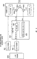
Fig. 4 is the block scheme that the configuration of controller in the imaging device of this embodiment and engine is shown;
Fig. 5 is the table that the example that is stored in the information in the color displacement amount storage unit is shown;
Fig. 6 is used to illustrate in coordinate transformation unit the view that the side-play amount of the integral part of color displacement correcting value is carried out correct operation;
Fig. 7 A~7F illustrates the view that utilizes the tint correction unit to carry out the operation of proofreading and correct less than the color displacement of pixel unit in this embodiment;
Fig. 8 is the block scheme that the configuration of the color displacement correcting unit among this embodiment is shown;
Fig. 9 illustrates the example that carries out the image in each processing of color displacement timing after having carried out halftone process;
Figure 10 illustrates the example of each image of handling when carrying out halftone process after having carried out the color displacement correction;
Figure 11 is the block scheme that the detailed configuration of coordinate counter 801 among Fig. 8 and coordinate transformation unit 802 is shown;
Figure 12 is the block scheme that illustrates according to the configuration of controller in the imaging device of second embodiment of the invention and engine;
Figure 13 is the block scheme that the configuration of the color displacement correcting unit among second embodiment is shown;
Figure 14 is used to illustrate the view that marginal portion of character/line image is not carried out the reason of conventional halftone process in a second embodiment;
Figure 15 is the process flow diagram that illustrates in a second embodiment based on the hand-off process of image border judged result;
Figure 16 is the block scheme that illustrates according to the configuration of controller in the imaging device of third embodiment of the invention and engine;
Figure 17 is the view that is illustrated in the relation between profile and the printing profile of exposing among the 3rd embodiment;
Figure 18 A to 18C is the view that is used to illustrate the relation between number of beams and the exposure inclination;
Figure 19 A to 19C is the view that is used to illustrate the relation between print speed and the exposure inclination;
Figure 20 is the block scheme that illustrates according to the configuration of the coordinate counter of fourth embodiment of the invention;
Figure 21 is the process flow diagram that the print processing sequence among the 4th embodiment is shown;
Figure 22 is the process flow diagram of handling sequence of writing in the table of corrections that illustrates among the 4th embodiment;
Figure 23 is the block scheme that illustrates according to the configuration of the coordinate counter of fifth embodiment of the invention;
Figure 24 is the view that the example of the pattern that will print in the renewal of exposure profile is handled according to sixth embodiment of the invention is shown;
Figure 25 is the block scheme that illustrates according to the configuration of the coordinate counter of seventh embodiment of the invention; And
Figure 26 is the process flow diagram that the print processing sequence among the 7th embodiment is shown.
Embodiment
Now, will describe the preferred embodiments of the present invention with reference to the accompanying drawings in detail.
First embodiment
Fig. 2 is the cut-open view that illustrates according to the structure of the imaging device of this embodiment.
As shown in Figure 2, the imaging device of this embodiment has the structure of 4 drum color laser beam printers.
This imaging device is installed in transfer sheet box 53 bottom on the right side of Fig. 2.Intake roller 54 picks up the print media (printing thin slice, transparent sheet etc.) that is placed in the transfer sheet box 53 one by one, and a pair of conveying roller 55-a and 55-b are fed into image-generating unit.This image-generating unit is provided with the transfer printing conveying belt 10 that is used to carry print media.Along print media throughput direction (in Fig. 2 from right to left), by a plurality of rollers with transfer printing conveying belt 10 tensioning Cheng Ping, in its upstream portion, print media by Electrostatic Absorption on conveying belt 10.With 4 photosensitive drums 14-C, 14-Y, 14-M and the 14-Ks of linear fashion arrangement as cydariform pattern load bearing component, make it face conveyor belt surface, thereby form image-generating unit (note that C, Y, M and K represent cyan, yellow, magenta and black component respectively).
Because except the color of the toner that held, the image-generating unit of each color component has same structure, thereby the following describes the image-generating unit of color component C.
The C image-generating unit has: charger 50-C is used for the surperficial uniform charging to photosensitive drums 14-C; Developing cell 52-C is used to hold the C toner, and makes the electrostatic latent image visible (development) that produces on photosensitive drums 14-C; And exposing unit 51-C.Between developing cell 52-C and charger 50-C, form predetermined gap.By this gap, the laser beam that is produced by the exposing unit 51-C that comprises laser scanner is with perpendicular to the scanning direction on the drawing plane surface by the photosensitive drums 14-C of charger 50-C uniform charging.Therefore, the exposed portion that is scanned has different electriferous states with unexposed portion, thereby forms electrostatic latent image.By toner is transferred on the electrostatic latent image, developing cell 52-C makes visible (the toner image formation of electrostatic latent image; Develop).
Transfer printing unit 57-C be arranged on transfer printing conveying belt 10 feed surface below.The transfer electric field that utilization is formed by transfer printing unit 57, the toner image electric attraction that will on the side face of photosensitive drums 14-C, form (development) to the print media of being carried, thereby it is transferred on the surface of print media.
Equally, other color components Y, M and K are repeated above-mentioned processing, so that C, M, Y and K toner are transferred on the print media successively.After this, melt by it is carried out heat, fixing device 58 makes the toner fixing of each color to print media, then, makes print media be discharged to the outside of device by a pair of distributing roller 59-a and 59-b.
Note that in the above example, the toner image of each color component is transferred on the print media.Yet, the toner image of each color component can be transferred on the transfer printing conveying belt, then, it is transferred to (secondary transfer printing) on the print media once more.In this case, transfer belt is called intermediate transfer belt.
Fig. 3 illustrates the image that is used to illustrate go up the skew of the main scanning line that scans as the photosensitive drums 14-C (or M, Y and K) of image bearing member.The direction of scanning of the horizontal direction among Fig. 3 (x direction of principal axis) expression laser beam, the sense of rotation (consistent) of vertical direction (y direction of principal axis) expression photosensitive drums with the throughput direction of print media.
In Fig. 3, the desirable main scanning line of Reference numeral 301 expressions.Reference numeral 302 expression produces because of the positional precision skew of the optical system in the exposing unit 51 of the skew of the positional precision of photosensitive drums 14 and diameter skew and every kind of color is inclined upwardly and the example of the actual main scanning line of bending.
When having the main scanning line of this degree of tilt and flexibility in the image-generating unit at random color, when being transferred to a plurality of toner images on the offset medium simultaneously, produce color displacement.
In this embodiment, be set to reference point (directions X) on the main scanning direction as the some A of the scanning starting position of print zone, and measure between desirable main scanning line 301 and the actual main scanning line 302 side-play amount along auxiliary scanning direction at a plurality of points (some B, C and D).At the each point of measuring side-play amount, main scanning line is divided into a plurality of zones (with the zone 2 between zone 1, Pb and the Pc between definition Pa and the Pb and the zone 3 between Pc and the Pd), utilizes the straight line (Lab, Lbc and Lcd) that connects consecutive point to be similar to the degree of tilt of the main scanning line in each zone.Therefore, when the difference between the side-play amount of consecutive point (m1 of zone in 1, m2-m1 in the zone 2 and m3-m2 in the zone 3) be on the occasion of the time, the main scanning line in the expression interesting areas has the degree of tilt that makes progress; Otherwise, represent that it has downward degree of tilt.In this embodiment, for convenience's sake, the quantity in zone is 3, but the present invention is not limited to this particular value.
Fig. 4 is used to illustrate the block scheme that is used in this embodiment to proofread and correct by the operation of the color displacement treatment for correcting of the inclination of sweep trace and the crooked and color displacement that produces.
With reference to figure 4, Reference numeral 401 expression Printer Engines, it carries out actual print processing according to the image bit map information that controller 402 produces.Controller 402 holds onboard, and when this plate was contained in the device, controller 402 was electrically connected to Printer Engine 401.
Color displacement amount storage unit 403C, 403M, 403Y and the 403K of this embodiment stores between actual main scanning line 302 and the desirable main scanning line 301 side-play amount along auxiliary scanning direction, as utilize as described in Fig. 3, in this side-play amount of a plurality of point measurements, as the degree of tilt of expression main scanning line and the information of flexibility.
Fig. 5 illustrates the example that is stored in the information in the color displacement amount storage unit 403C (be equally applicable to unit 403M, 403Y and 403K, but institute's canned data depending on difference separately).In Fig. 5, L1 to L3 and m1 to m3 have identical meaning with identical symbol among Fig. 3.
In this embodiment, color displacement amount storage unit 403C, 403M, 403Y and 403K store the side-play amount between desirable main scanning line and the actual main scanning line.Yet as long as information can be discerned the degree of tilt and the flexibility characteristic of actual main scanning line, the present invention is not limited to this concrete amount.As mentioned above, by in manufacture process, measuring side-play amount, the information of store storage in each color displacement amount storage unit 403C, 403M, 403Y and 403K in advance, as this device exclusive information.Alternatively, in this device itself, can be provided for detecting the testing agency of side-play amount, can store the side-play amount of the skew of each that predetermined pattern obtains by forming, as to be used to measure each color image bearing member, and utilize testing agency its result who detects.
View data by proofreading and correct each color component is stored in main scanning line side-play amount in color displacement amount storage unit 403C, 403M, 403Y and the 403K with elimination, and controller 402 is carried out print processing.The following describes the controller 402 of this embodiment.
According to the coordinate information on the main scanning direction, based on the information of the color displacement amount that is stored in the main scanning line in color displacement amount storage unit 403C, 403M, 403Y and the 403K, color displacement correcting value arithmetic element 407C, 407M, 407Y and 407K calculate the color displacement correcting value on the auxiliary scanning direction.Color displacement correcting value arithmetic element 407C, 407M, 407Y and 407K output to its result of calculation color displacement correcting unit 408C, 408M, 408Y and the 408K that is used to be provided with corresponding correcting value respectively.
If x (point) is the coordinate data on the main scanning direction, y (point) is the color displacement amount on the auxiliary scanning direction.In this case, the following describes based on the mathematical formulae on each zone of Fig. 3 (supposing that the print resolution among this embodiment is 600dpi):
Zone 1:y=x * (m1/L1)
Zone 2:y=m1 * 23.622+ (x-L1 * 23.622) * ((m2-m1)/(L2-L1))
Zone 3:y=m2 * 23.622+ (x-L1 * 23.622) * ((m3-m2)/(L3-L2)) ... (1)
Wherein, L1, L2 and L3 are to the distance (unit: mm) of the right-hand member in zone 1,2 and 3 from the scanning starting position of print zone.In addition, m1, m2 and m3 are the side-play amounts between desirable main scanning line 301 of the right-hand member in zone 1,2 and 3 and actual main scanning line 302.
According to color displacement amount arithmetic element 407C, 407M, 407Y and 407K color displacement correcting value to each point calculating, color displacement correcting unit 408C, 408M, 408Y and 408K regulate be stored in the data bitmap in bit image memory 406C, 406M, 406Y and the 406K output regularly and to the exposure of each pixel, the color displacement that produces because of the degree of tilt of the main scanning line that formula (1) provides and distortion to proofread and correct, thus when being transferred on the offset medium, the toner image with each color makes color displacement (locating bias).
Color displacement correcting unit 408C, 408M, 408Y and 408K have different correcting values respectively, but have identical configuration.Therefore, the following describes the color displacement correcting unit 408C of C component.
Fig. 8 is the block scheme that the configuration of the color displacement correcting unit 408C among this embodiment is shown.
As shown in Figure 8, the color displacement correcting unit 408C of this embodiment comprises: coordinate counter 801, coordinate converter 802, line buffer 803 and tint correction device 804.
Coordinate counter 801 outputs produce the required information of coordinate on main scanning direction and the auxiliary scanning direction, wherein, according to formula (1) coordinate converter 802 is carried out the color displacement treatment for correcting, the information of the drift rate (value behind the radix point will illustrate below) on the expression auxiliary scanning direction is outputed to tint correction device 804.
Be used to the coordinate position data (Y address) on coordinate position data on the main scanning direction of coordinate counter 801 (X address) and auxiliary scanning direction, 802 couples of bit image memory 406C of coordinate converter read.As a result, the data (being the C component data in this case) of reading are outputed to line buffer 803.
Figure 11 illustrates the coordinate counter 801 of this embodiment and the example of coordinate converter 802.
As precondition, color displacement correcting value arithmetic element 407C calculates corresponding to location of pixels L1 ', L2 ' and L3 ' on the horizontal direction (ideal scan direction) of L1, L2 and L3 according to the distance L 1, L2 and the L3 that are stored in the color displacement correcting value storage unit 403C.In addition, color displacement correcting value arithmetic element 407C also calculates the degree of tilt of the straight line relevant with each regional side-play amount.Note that degree of tilt is the degree of tilt to each pixel, y represents by Δ.
Example for shown in Figure 5 has:
Zone 1: Δ y1=m1/L1
Zone 2: Δ y2=(m2-m1)/(L2-L1)
Zone 3: Δ y3=(m3-m2)/(L3-L2)
After the correction data of the single pass that has generated laser beam, the X address generator 81 that resets, and by adding that pixel clock clk produces the address of reading on the horizontal direction, the X address of the figure storer 406C that ascends the throne.Therefore, when each input pixel clock clk, the X address increment, for example 0,1,2 ....
Before carrying out single pass, first reset counter 86 adds up in internal register 86a from the degree of tilt Δ y of selector switch 85 outputs, and keeps this value.Because degree of tilt Δ y comprises fraction part, so this register 86a has suitable figure place.Counter 86 outputs to Y address generator 87 with the integral part of the register 86a that itself keeps, and fraction part is outputed to tint correction device 804.
Before carrying out single pass, utilize the benchmark Y address in the bit image memory 406C that Y address generator 87 is set, with benchmark Y address and integral part addition, and produce the result who reads Y address as bit image memory 406C from counter 86.
Therefore, can produce the X address and the Y address of the integer in the formula (1), and the C component data of relevant position can be read in line buffer 803.
A more real example will be described below.Suppose that the benchmark Y address is " 100 ".That is be that the 100th scanning produces data.In addition, suppose that the value in the register 86a that is stored in counter 86 is " 0.1 ".
At this moment, pack into the in theory pixel data of the Y coordinate position " 100.1 " that is positioned at bit image memory 406C.Yet, because the location of pixels of bit image memory 406C in round figures, so there is not Y coordinate " 100.1 ".From another viewpoint, can think that coordinate " 100.1 " is positioned between address " 100 " and " 101 ", 90% (carrying out after the tint correction) of the pixel value that calculates is subjected to the influence of the pixel value of address " 100 ", and remaining 10% is subjected to the influence of the pixel value of address " 101 ".That is, utilize weighting coefficient, can calculate tint correction value afterwards according to the value that fraction part is represented.That is it is as follows, to provide this value:
H
x,y=C
x,y×β+C
x,y+1×α ...(2)
If γ is the value of the fraction part of counter 86 outputs.Then, α and β have following relation of plane:
β=1-γ
α=γ
Note that when each scanning, make the benchmark Y address increase progressively " 1 ", amount remains unchanged but the color displacement correcting value of this benchmark Y address promptly is offset (offset).
If P and Q are X address and the Y addresses that is produced by coordinate converter 802, the skew of this Y address is 0.1.Then, register 805 coordinate (P, the data of Q) locating of bit image memory 406C of packing into.In this case, be in interpolate value is handled (P, Q+1), if regard register 805 as the pixels of interest position, then not packing into as yet is positioned at coordinate (P, data Q+1) in the reference pixel position.
For this reason, this embodiment has following relation of plane: be from the data of fifo buffer 806 output pixels of interest (P, C component data Q) to be from the data of register 805 outputs (P, Q+1), as shown in Figure 8.As mentioned above, because for each scanning, it is identical that the side-play amount of Y address keeps,, can realize the colourity interpolate value so be used to value from the fraction part of coordinate counter 801.
Configuration and the operation to the color displacement correcting unit 408c among this embodiment is illustrated, and below with reference to Fig. 6 it is described in detail.
In Fig. 6, the color displacement curve that Reference numeral 60 expressions are drawn according to the information that is stored in the color displacement amount storage unit 403C.The degree of tilt in zone 1 is Δ y1, and the degree of tilt in zone 2 is Δ y2.
State data memory in the Reference numeral 61 expression bit image memory 406C; 62 (Fig. 6) are illustrated in each pixel on the image bearing member had been carried out view data that color displacement the proofreaies and correct exposure image when exposing.In addition, the positive dirction of the sub-scanning of bit image memory 406C is about the downward direction in the plane of this figure, shown in Reference numeral 61.
As shown in Figure 6, when upgrading the X address, Δ y1 successively adds up.Yet,, represent that n is capable so Y address remains owing to before the Xa of address, do not occur to the carry of integer number.
When arrival address Xa, carry is to integer number, and Y address is updated to expression (n+1) OK.
X address in Fig. 6 be Xb, Xc, Xd ... the time, this integer carry takes place.Note that carry takes place with the different cycles in zone 1 and 2.This is because these zones have different degree of tilt.
Fig. 7 A to 7F illustrates the color displacement that is used to illustrate less than a pixel unit and proofreaies and correct, that is, in this embodiment, utilize tint correction device 804 to come the content of operation of side-play amount of the fraction part of correction of color shift correct tilt degree Δ y.By regulating the exposure ratio of two consecutive point on the auxiliary scanning direction, proofread and correct the side-play amount of fraction part.
Fig. 7 A illustrates the image of acclivitous main scanning line.Fig. 7 B illustrates and carries out tint correction horizontal bitmap images before, and Fig. 7 C illustrates the correcting image that is used to eliminate the color displacement that produces because of the inclination of the main scanning line shown in Fig. 7 A.In order to produce the correcting image shown in Fig. 7 C, regulate the exposure of two consecutive point on the auxiliary scanning direction.Fig. 7 D is the table that color displacement correct tilt degree Δ y is shown and is used to realize the relation between the correction coefficient of tint correction.K is the integer (fractions omitted part) of color displacement correction amount delta y, and it represents the correcting value on the auxiliary scanning direction of each pixel.β and α apply correction coefficient less than the correction of pixel unit at auxiliary scanning direction, and it concerns by top formula (2) explanation.That is, α is the distribution factor of previous point (data of register 805 outputs from Fig. 8), and β is the distribution factor of interested point.
Fig. 7 E is illustrated in the tint correction bitmap images afterwards of the exposure ratio of having carried out two consecutive point that are used to regulate on the auxiliary scanning direction.Fig. 7 F illustrates the exposure image of the bitmap images of the tint correction on the image bearing member.In Fig. 7 F, eliminated the degree of tilt of main scanning line, formed horizontal linear.
The color displacement correcting unit 408C to this embodiment is illustrated.Because this can be applicable to color displacement correcting unit 408M, 408Y and the 408K of other color components M, Y and K equally,, the color displacement between can print colors is no more than a pixel so being set to maximum.
In follow-up halftone process device 409C, 409M, 409Y and 409K, utilize predetermined halftone pattern, to carrying out halftone process from color displacement correcting unit 408C, 408M, 408Y and the color displacement of 408K output and the data of tint correction, then, carrying out width modulation in PWM processor 410C, 410M, 410Y and 410K handles.Then, these data are outputed to Printer Engine 401, thereby on image bearing member, carry out exposure-processed.
As mentioned above, calculate the correcting value that is used to proofread and correct each side-play amount of main sweep position on auxiliary scanning direction from image bit map, this correcting value of reconstruct is as the image bit map after proofreading and correct, thus the image that the color displacement that generation produces because of the inclination of main scanning line and distortion obtains proofreading and correct.
The following describes the comparative result when when carrying out processing and with the order of input picture being carried out color displacement correction → halftone process, carrying out processing with the order of input picture being carried out halftone process → color displacement correction.
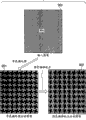
Fig. 9 is illustrated in input picture is carried out order that halftone process → color displacement the proofreaies and correct example when handling.In Fig. 9, the input picture of the fixed concentration of Reference numeral 900 expressions 50%.When utilizing 4 * 4 halftone patterns that input picture 900 is carried out halftone process, obtain image 901.This image 901 is the images that will obtain.Yet,, when obtaining to be equivalent to the image of image 901, also can carry out the color displacement that does not cause image degradation and proofread and correct even after image 901 having been carried out the color displacement correction.When carrying out 1/2 pixel color offset correction to having carried out the image after the halftone process, obtain the image of representing with Reference numeral 902 among Fig. 9 with the direction (vertical direction) that makes progress.As can be seen from Figure 9, when carrying out the color displacement timing to having carried out the image after the halftone process, the repeatability of the half tone dot of the half tone image that is produced by halftone process is worsened.
Example when as a comparison, Figure 10 is illustrated in and carry out handles with the order of input picture being carried out color displacement correction → halftone process.In Figure 10, Reference numeral 100 expression input pictures, it has the fixed concentration (50%) identical with above-mentioned image 900.When this input picture 100 being used the 1/2 pixel color offset correction of (vertical direction) in the upward direction, obtain image 101.As the result that color displacement is proofreaied and correct, the part in highest and lowest delegation, formation concentration are 25% image.After having carried out the color displacement correction,, obtain image 102 shown in Figure 10 by this image is carried out halftone process.Except highest and lowest delegation, image 102 is basic identical with image 901.On image 102, do not observe on image 902 can observed half tone image half tone dot worsen, therefore, can obtain high-quality coloured image.
Note that and halftone process among this embodiment produce 4 * 4 (generalized case is the pattern of m * n) from input image data.Since 4 * 4, represent so can produce 16 kinds of different tones.To a grid of 4 * 4 patterns, specify four (16 tone) multi-value datas, and carry out PWM and handle, therefore, this 4 * 4 pattern can be represented 256 tones.
In this embodiment, utilize Fig. 8 and 11 for example to understand the setting (can be applied to other color components equally) of color displacement correcting unit 408C.In configuration shown in Figure 11,, obtain skew (offset) (skew) amount of Y address by the Δ y that in the register 86a of counter 86, adds up successively.The operational precision of the fraction part of register 86a is preferably high as far as possible.In other words, when the figure place of register 86a after a little while, during the Δ y that adds up, produce round-off error gradually, degree of tilt Δ y1 in the value slip chart 6 of register and the path of Δ y2.
Therefore, be used for when bit image memory 406C packs the X address of data into, can calculate the side-play amount of Y address according to equation (1) each the renewal.Owing to not existing because the round-off error that adds up and produce, so can read pixel data by the represented position of normal route.
Can also utilize software (firmware) to realize configuration shown in Figure 4.In this case, can carry out the processing that allows image to flow according to Fig. 4, by the explanation to present embodiment, this implementation is to realize easily for a person skilled in the art.
As mentioned above, according to first embodiment, at first pass through offset information according to the side-play amount of the direction of scanning on the image bearing member of each image-generating unit of expression, calculate the coordinate reading position of the view data that will print, carry out color displacement and proofread and correct, carry out halftone process then with print image, therefore, suppressed the ripple of generation, thereby formed high-quality image because color displacement proofreaies and correct.
Second embodiment
The following describes second embodiment.
Figure 12 is used for explanation in a second embodiment, is used to proofread and correct because the block scheme of the operation of the color displacement treatment for correcting of any color displacement that the inclination of sweep trace produces with bending.Fig. 4 among first embodiment and the difference of Figure 12 are, utilize unit 408C ', 408M ', 408Y ' and 408K ' to replace color displacement correcting unit 408C, 408M, 408Y and 408K.In addition, except color displacement is proofreaied and correct 408C, 408M, 408Y and 408K, add exception processor 411C, 411M, 411Y and 411K, and added one selector switch 412C, 412M, 412Y and 412K of the output of the output that is used for selecting halftone process device 409C, 409M, 409Y and 409K and exception processor 411C, 411M, 411Y and 411K.
Other configurations are identical with the configuration of first embodiment, the following describes its difference.
Color displacement correcting unit 408C ', 408M ', 408Y ' and 408K ' have different correcting values respectively, but its configuration is identical.Therefore, the following describes the color displacement correcting unit 408C ' of C component.
Figure 13 is the block scheme that the color displacement correcting unit 408C ' among second embodiment is shown.In the configuration of Figure 13 identical Reference numeral represent with Fig. 4 of first embodiment configuration in identical part.
The color displacement correcting unit 408C ' of second embodiment comprising: coordinate counter 801, coordinate converter 802, line buffer unit 1803, third edge pattern storer 1805, edge detector 1806 and tint correction device 804.In these parts, coordinate counter 801, coordinate converter 802 and tint correction device 804 are with shown in Figure 4 identical.
With identical in first embodiment, coordinate counter 801 will output to coordinate converter 802 at main scanning direction and the required information of auxiliary scanning direction generation coordinate, wherein, carry out the color displacement treatment for correcting according to formula (1), and will represent that the information (value of radix point back is done explanation below) along the drift rate of auxiliary scanning direction outputs to tint correction device 804.
With identical in first embodiment, utilization from the main scanning direction of coordinate counter 801 output coordinate position data (X address) and the coordinate position data (Y address) on the auxiliary scanning direction, 802 couples of bit image memory 406C of coordinate converter carry out read access.Therefore, the data (being the C component data in this case) of reading are outputed to line buffer unit 1803.
3 * 3 window datas that edge detector 1806 will be imported compare with the pattern that is stored in the third edge pattern storage unit 1805, and whether the check pixels of interest that is positioned at the center of this window belongs to the marginal portion of character/line image etc.If be judged as the marginal portion that pixels of interest belongs to character/line image, then edge detector 1806 outputs to tint correction device 804 with the pixel data Pn+1 (x) (line buffer 1803a) at pixels of interest P (x) (being used to store the line buffer 1803b of the capable view data of n) and the identical main sweep coordinate position place that is positioned at (n+1) row, and this tint correction device 804 is carried out tint correction.
On the other hand,, that is,, then skip tint correction, carry out shadow tone by halftone process device 409C and proofread and correct if be judged as the tone images that pixels of interest belongs to photograph image for example etc. if be judged as the edge that pixels of interest does not belong to character/line image.
At this moment, whether expression edge detector 1806 detects the signal at edge, whether finds in third edge pattern storer 1805 that promptly the signal of matched patterns is output to selector switch 412C.Therefore, selector switch 412C selects one of them data from exception processor 411C and halftone process device 409C, and exports selected data.
The processing to the color correction unit 408C ' of second embodiment is illustrated.This can be applied to color displacement correcting unit 408M ', 408Y ' and the 408K ' of other color components equally.
Note that according to second embodiment, utilize tint correction device 804 carry out tint correction to as if the marginal portion of character/line image etc.
The following describes exception processor 411C, 411M, 411Y and the 411K of second embodiment.
The following describes input picture is carried out order that halftone process → color displacement proofreaies and correct situation when handling and the situation when handling with the order of input picture being carried out color displacement correction → halftone process.
Fig. 9 is illustrated in input picture is carried out order that halftone process → color displacement the proofreaies and correct example when handling.In Fig. 9, the input picture of the fixed concentration of Reference numeral 900 expressions 50%.When utilizing 4 * 4 given halftone patterns that input picture 900 is carried out halftone process, obtain image 901.This image 901 is the images that will obtain.Yet,, when obtaining to be equivalent to the image of image 901, also can carry out the color displacement that does not cause image degradation and proofread and correct even after image 901 having been carried out the color displacement correction.When carrying out 1/2 pixel color offset correction to having carried out the image after the halftone process, obtain the image of representing with Reference numeral 902 among Fig. 9 with the direction (vertical direction) that makes progress.As can be seen from Figure 9, when carrying out the color displacement timing to having carried out the image after the halftone process, the repeatability of the half tone dot of the half tone image that is produced by halftone process is worsened.
Example when as a comparison, Figure 10 is illustrated in and carry out handles with the order of input picture being carried out color displacement correction → halftone process.In Figure 10, Reference numeral 100 expression input pictures, it has the fixed concentration (50%) identical with above-mentioned image 900.When this input picture 100 being used the 1/2 pixel color offset correction of (vertical direction) in the upward direction, obtain image 101.As the result that color displacement is proofreaied and correct, the part in highest and lowest delegation, formation concentration are 25% image.After having carried out the color displacement correction,, obtain image 102 shown in Figure 10 by this image is carried out halftone process.Except highest and lowest delegation, image 102 is basic identical with image 901.On image 102, do not observe on image 902 can observed half tone image half tone dot worsen, therefore, can obtain high-quality coloured image.
That is, as 900 and 100, do not have the image at edge,, can suppress image degradation by carrying out halftone process to having carried out the image that color displacement proofreaies and correct for image pattern.
On the other hand, for concentration as character, line image etc. with respect to the image border part of the unexpected variation of peripheral part, as shown in figure 14, because by carrying out halftone process, form the marginal portion according to halftone pattern, so tint correction is invalid, partly produce gap and discontinuous in the edge of image that produces by exposing clearance, shown in the Reference numeral among Figure 14 1100.Therefore, produce uneven (jaggy) in part such as the image border of character/line image etc.
In order to prevent this situation, for the image border part of character/line image etc. having been carried out the processing that makes an exception of image after color displacement is proofreaied and correct.
There is following 3 types exception to handle.
1, do not use (by) halftone process.In this case, owing to the image that is detected the edge by edge detector 1806 is not carried out halftone process, so can prevent the gap that produces in the marginal portion because of halftone process and discontinuous.
2, use halftone pattern that halftone process is carried out in the marginal portion.When using conventional halftone pattern, as shown in figure 14,, produce gap and discontinuous according to the direction of growth of halftone pattern in the marginal portion.Therefore, when having when the halftone pattern of the direction of growth of conventional halftone pattern is used for this marginal portion, can prevent to adopt gap that conventional halftone pattern produces and discontinuous.
3, after having carried out conventional halftone process etc., be used for the processing that point is offset.After having carried out conventional halftone process, to gap and discontinuous part offset point, with skew gap and discontinuous.Like this, can be to any gap and discontinuous skew that produces by conventional halftone process.
Relative with it, halftone process device 409C (can be applicable to processor 409M, 409Y and 409K equally) carries out conventional halftone process to the image that does not have the marginal portion.
Can carry out a series of treatment schemees, as shown in figure 15.
At step S121, utilize coordinate converter 802 to carry out coordinate transform, so that the color displacement that is equal to or greater than delegation is proofreaied and correct.
At step S122, will be by the data storage after the conversion of coordinate converter 802 acquisitions to line buffer unit 1803.
At step S123, the marginal portion of edge detector 1806 detection character/line images etc.If detect the edge, then this flow process enters step S124; Otherwise this flow process enters step S125.
At step S124, the image that 804 pairs of tint correction devices have the marginal portion carries out tint correction, to carry out less than a color of pixel offset correction.Then, carrying out exception in step 126 handles.That is, carry out exception and handle, for example, utilizes the halftone pattern different with conventional pattern carry out halftone process, to the processing of the discontinuous part that produces by halftone process and gap interpolation etc.
On the other hand, if detect the image that does not have the edge, then carry out halftone process at step S125.
According to the view data that obtains from one of above-mentioned exception processor 411C or halftone process device 409C, carry out width modulation, it is transformed to the scale-of-two laser-driven signal, then, this scale-of-two laser-driven signal is offered exposing unit expose.The processing identical with above-mentioned processing can be applicable to other color components M, Y and K equally.
As mentioned above, according to second embodiment, at first, calculate the coordinate reading position of the view data that will print, proofread and correct thereby carry out color displacement by according to the offset information of expression with respect to the side-play amount of the direction of scanning on the image bearing member of each image-generating unit.After this, carry out halftone process, therefore, suppressed the ripple that produces because color displacement proofreaies and correct with print image.In addition,, can suppress to produce uneven, therefore, can form high-quality image for the edge of character/line image.
The 3rd embodiment
The following describes the 3rd embodiment.
Figure 16 is used for explaining the block scheme that is used for the random color that produces because of the inclination of sweep trace and bending is offset the operation of the color displacement treatment for correcting of proofreading and correct at the 3rd embodiment.The Figure 12 of second embodiment and the difference between Figure 16 are that engine 401 comprises exposure profile storage unit 1403C, 1403M, 1403Y and 1403K, and prints profile storage unit 1420.Dispose color displacement correcting value arithmetic element 1407C, 1407M, 1407Y and 1407K based on this.
Exposure profile storage unit 1403C, 1403M, 1403Y and 1403K store identical data with color displacement amount storage unit 403C, 403M, 403Y and 403K among first and second embodiment.That is, in the manufacture process of device, exposure profile storage unit 1403C, 1403M, 1403Y and 1403K receive and keep the offset information of the corresponding image-generating unit of each color.For example, utilize EEPROM for example etc. write, nonvolatile memory can realize each exposure profile storage unit.In Figure 16, be each color component profile storage unit of guaranteeing to expose.Yet, owing to want the canned data size enough little, so the color displacement amount that memory element can be stored whole color components.
Print the profile storage unit 1420 storages configuration information relevant with the print processing of Printer Engine 401.Print profile storage unit 1420 also comprise can write, nonvolatile memory.
According to the data from exposure profile storage unit 1403C and printing profile storage unit 1420, color displacement correcting value arithmetic element 1407C (can be applicable to unit 1403M, 1403Y and 1403K equally) calculates the color displacement correcting value.
Because except above-mentioned configuration, other configurations are identical with second embodiment's, thus utilize identical Reference numeral to represent these parts, and with reference to the explanation of first and second embodiment to it.
Exposure profile storage unit 1403C (can be applicable to unit 1403M, 1403Y and 1403K equally, but institute's canned data has nothing in common with each other) color displacement amount storage unit 403C, the data that 403M, 403Y are identical with 403K among storage and first and second embodiment, as mentioned above.Therefore, identical based on the processing of these data and first and second embodiment only, thereby omit its explanation.
The characteristic of the 3rd embodiment is, considers that being stored in the information of printing in the profile storage unit 1420 calculates the color displacement correcting value.
Figure 17 illustrates the exposure profile that is stored in the exposure profile storage unit 1403 and is stored in the relation of printing between the interior printing profile of profile storage unit 1420.
Utilize Figure 18 A to 18C, the degree of tilt (quantity that Figure 17 illustrates the light beam that is produced by each image-generating unit is 4) based on the quantity of scan exposure direction and scanning light beam is described.
Figure 18 A illustrates an example, all scans 1 row when wherein scanning at every turn, and the direction of scanning of M (magenta) component and C (cyan) component is opposite mutually.Figure 18 B illustrates the example (two pairs laser diode and polygonal mirror) of 2 row of each scanning.Figure 18 C illustrates the example of 4 row of each scanning.
The following describes the example shown in Figure 18 A.The exposure starting position of image is 4m for magenta, and is 4c for cyan.Yet,, be 4m ' and 4c ' so work as the position of the scanning time point of finishing the main sweep image area because the direction of scanning of these color components faces toward mutually.If Lmax is the displacement (exposure range) of light beam when scanning at every turn, mdot is the distance between the point.Therefore, provide the degree of tilt that concerns based on above-mentioned position below:
mdot/Lmax
Degree of tilt based on the some position of Figure 18 B and 18C relation is:
2 light beams: 2 * mdot/Lmax
4 light beams: 4 * mdot/Lmax
The quantity of the light beam that if n is each scanning to be used.Therefore, it is as follows to provide degree of tilt:
n×mdot/Lmax
In addition, if the offset direction among Fig. 3 is positive, then has negative sign for forward scan, and have positive sign for reverse scan by degree of tilt being carried out the arithmetical operation that accumulated counts carries out.
Figure 19 A to 19C illustrates when the asynchronous example of print speed.Utilize Figure 19 A to 19C that these examples are described.
Example when Figure 19 A illustrates normal speed, the example when Figure 19 B illustrates a half speed, the example when Figure 19 C illustrates twice speed.
Shown in Figure 19 B, for Half Speed (rotating speed of photosensitive drums is half of normal speed), handle owing in a main sweep of twice main sweep, carry out image output, thus carry out arithmetical operation, so that the inclination coefficient of the degree of tilt of calculating according to the quantity of light beam reduces by half.
Shown in Figure 19 C, for speed doubly, carry out twice scanning owing to photoreceptor is moved during each main sweep, thus carry out arithmetical operation, so that the inclination coefficient of the degree of tilt of calculating according to the quantity of light beam doubles.
If print speed be normal speed k doubly, provide the degree of tilt that quantity and print speed according to light beam obtain below then:
k×n×mdot/Lmax
Therefore, for the forward scan direction, the following skew y that is given in the Zone Full along auxiliary scanning direction and benchmark Y coordinate, Ldot represent that length is the quantity of " L " point in (mm):
y=-x×k×n×mdot/Lmax+x×(m1/L1) (0≤x<L)
=-x×k×n×mdot/Lmax+m1/Ldot+(x-L/Ldot)×(m2/L)?(L≤x<2L)
=-x×k×n×mdot/Lmax+(m1+m2)/Ldot+(x-2L/Ldot)×(m3/L)
(2L≤x≤3L)
Note that and calculate in Fig. 3, to make L2=2 * L1, L3=3 * L1.
For the reverse scan direction,
y=x×k×n×mdot/Lmax+x×(m1/L1) (0≤x<L)
=x×k×n×mdot/Lmax+m1/Ldot+(x-L/Ldot)×(m2/L) (L≤x<2L)
=x×k×n×mdot/Lmax+(m1+m2)/Ldot+(x-2L/Ldot)×(m3/L)
(2L≤x≤3L)
In print processing, the exposure starting position is different with the difference of antiquarian.That is, must change the deviation post of X address.Because this reason, be used for y that auxiliary scanning direction at image carries out coordinate transform processing and begin from the Yobj of deviation post.Utilization is used to calculate the formula of y, can calculate vertically the correcting value at the deviation post place.
Therefore, when adopting configuration shown in Figure 3, can be forward or reverse according to the exposure directions of each image-generating unit, the position in each district is set in register shown in Figure 11 82, and the synthetic degree of tilt based on exposure and printing profile can be set in register 84.
As mentioned above, according to for addressing the above problem the 3rd embodiment that makes, at first, by according to the offset information of expression with respect to the side-play amount of the direction of scanning on the image bearing member of each image-generating unit, proofread and correct thereby carry out color displacement the coordinate reading position of the view data that calculating will be printed.After this, carry out halftone process, therefore, suppressed the ripple that produces because color displacement proofreaies and correct with print image.In addition,, can suppress to produce uneven, therefore, can form high-quality image for the edge of character/line image.
The 4th embodiment
In first to the 3rd embodiment, being used for of utilizing that configuration shown in Figure 11 generates example from the address of each view data of packing into of bit image memory 406C, 406M, 406Y and 406K has been described.
When adopting configuration shown in Figure 11, each when upgrading the X address, must accumulated counts comprise the Δ y of radix point.Once you begin one page is carried out scan exposure, as long as the X coordinate is identical to each scanning, then the side-play amount to Y-axis remains unchanged.Therefore, can utilize arithmetical operation calculated in advance Y-axis offset address and weighting coefficient, and it is stored in the table.When actual scanning, can when handling, show to read the weighting coefficient that is used to carry out coordinate transform and tint correction with reference to this.
Figure 20 is illustrated in the configuration of coordinate counter 801 when carrying out this processing, and Figure 21 illustrates the flow process of the processing relevant with this configuration.
As mentioned above, this calculation process only needs the state (comprising printing model) according to engine once to judge.CPU (not shown) in this image processing apparatus is carried out calculation process, and its result is stored in the correction calculation table 623.When the starting image processing apparatus, perhaps when changing print speed, carry out this and write processing.When CPU (not shown) request visit correction calculation table 623, selector switch 622 is searched address 65 with table and is offered correction calculation table 623 as table address 64.When CPU does not carry out any visit, use coordinate address from totalizer 621 as table address 64.At this moment, according to the size and Orientation of print media, utilize skew (O1 among Figure 17, O2, O3 etc.) to be provided for storing the register 620 of off-set value.
When the beginning print processing, owing to the size and Orientation of the thin slice that will print is determined, so CPU writes the skew that off-set value register 620 is provided with this X address by the skew with the X address as offset data 610.
In above-mentioned configuration, CPU begins to write successively correction calculation table 623 with the integral part of degree of tilt Δ y sum and weighting coefficient α and β from the X address offset.In the table below, suppose degree of tilt Δ y=+0.2.
Write address Y address skew weighting coefficient α weighting coefficient β
0 0 0.0 1.0
1 0 0.2 0.8
2 0 0.4 0.6
3 0 0.6 0.4
4 0 0.8 0.2
5 1 0.0 1.0
6 1 0.2 0.8
7 1 0.4 0.6
8 1 0.6 0.4
According to the X address, coordinate counter 801 offers coordinate converter 802 with corresponding Y address off-set value.Meanwhile, coordinate counter 801 will be worth α and β outputs to tint correction device 804.Therefore, because coordinate converter 802 can not need to comprise the addition process of radix point, and tint correction device 804 do not need to carry out the processing that is used to calculate α and β, therefore reduced burden.
According to process flow diagram shown in Figure 21, can carry out the processing when carrying out above-mentioned processing in this embodiment.The processing of C component only is described below, but it can be applicable to other components equally.Note that and to describe with reference to the 3rd embodiment.
At step S1701, from exposure profile storage unit 1403C (can be applicable to unit 1403M, 1403Y and 1403K equally) the exposure profile of packing into.At step S1702, from printing the profile storage unit 1420 printing profile of packing into.
After this, this flow process enters step S1703, considers that printing model size and throughput direction, the print speed etc. of thin slice (print) calculates the correction data (X address deviant, Y address off-set value and weighting coefficient α and β) based on these profiles.At step S1704, with the appropriate address position of these data storage of calculating to correction calculation table 623.
At step S1705, whether the check printing model is changed.Be changed if be judged as printing model, then the processing of execution in step S1703 and S1704 once more.That is, upgrade the content of correction calculation table 623.
Begin to print processing if detect at step S1706, then this flow process enters step S1707, with the off-set value of packing into from correction calculation table 623.At step S1708, determine coordinate data.At step S1709, read the data that are positioned at the corresponding coordinate position from bit image memory 406C.At step S1710, carry out treatment for correcting (interpolate value is handled, made an exception and handle).Then, repeat the processing of step S1708 and subsequent step, finished print processing up to being judged as at step S1711.
As handling at the correction calculation of step S1703 and, can carrying out processing shown in Figure 22 in the processing of writing of step S1704.Describe with reference to Figure 22.
At step S1801 and S1802, pack into exposure profile and printing profile.At step S1803, the variable x of expression X address is reset to " 0 ".
After this, at step S1804, for variable x calculates Y address off-set value and weighting coefficient α and β.At step S1805, the data that calculate are write in the correction calculation table 623.Afterwards, whether surpass the variable ymax (under original state, being reset to 0) that keeps peak excursion in step S1806 check Y address off-set value.Surpass ymax if be judged as off-set value, then utilize the Y address off-set value of this moment to upgrade ymax (step S1807).
At step S1808,, check the skew arithmetic operation of whether having finished delegation by the variable x of this moment and the end coordinate xend of delegation are compared.If at step S1808 is "No", then make variable x increase progressively " 1 ", then the processing of repeating step S1804 and subsequent step at step S1809.
If be judged as the skew arithmetic operation of having finished delegation, then this flow process enters step S1810, whether surpasses " 1 " to check final Y-axis off-set value ymax.If at step S1810 is "No", then owing to do not need to proofread and correct, thereby this flow process enters step S1811, all is written as 0 in correction calculation table 623.
The 5th embodiment
When the interested type information of color converting unit 405 indications represented to use monochrome promptly only to use an image-generating unit to print processing, color displacement did not take place.Therefore, in this case, can ignore each profile, and " 0 " unconditionally can be write the correction calculation table.
Whether to carry out the correction of color displacement amount in order checking, in each color displacement amount arithmetic element, additionally to be provided for estimating the peaked value of ymax.If ymax greater than this estimated value, proofreaies and correct even then monochromatic print processing is also carried out color displacement.
Figure 23 is used to replace Figure 20 to carry out the block scheme of this processing.
In Figure 23, signal 91 to 98 and parts 920 to 923 are identical with signal 61 to 68 and parts 620 to 623 among Figure 20.Be to be provided with the difference of Figure 20: maximum value detector 928 is used to detect ymax; Register 926 is used to store the boundary value that is used to judge whether to carry out the color displacement correction; Judging unit 927; And selector switch 925.
That is, when selecting monochromatic mode, and the data of maximum value detector 928 outputs are when being equal to or less than data in the register 926, and judging unit 927 control selector switchs 925 so that output " 0 " unconditionally, thereby forbid that color displacement proofreaies and correct.Under other conditions, judging unit 927 control selector switchs 925 are selected data from correction calculation table 923.
The 6th embodiment
In the explanation of the 3rd embodiment, in factory's manufacture process, the profile information that will expose writes among each exposure profile storage unit 1403C, 1403M, 1403Y and the 1403K.Yet, because device may comprise many mechanically actuated parts etc., so may be because aging and make this information with different when factory delivers.
Therefore, the 6th embodiment illustrates the situation of controller 402 sidelights on and each exposure profile storage unit 1403 of renewal.In order to rewrite content, this device comprises the circuit that is used for information is write exposure profile storage unit 1403.Yet, because this circuit is known for a person skilled in the art, so omit its explanation.In order to upgrade the exposure profile, will the detection of the color displacement amount of exposing unit be described.
In the 6th embodiment, as shown in figure 24, go up exposure delegation dot pattern in the pre-exposure zone of photosensitive drums (in conventional print processing, do not adopt, and its length (counting) being Lpat), and it is transferred on the printing thin slice.After this, detect the coordinate position of right-hand member and left end.At this moment, if photosensitive drums is normal, the pattern 2009 that then is positioned at the right-hand member of row a bit and left end and 2008 detection are regularly only according to the length of printing profile and different.That is,, detect these patterns in the moment with difference k * m/Lpat for conventional photosensitive drums.
Therefore, be expose this moment right-hand member of profile and the side-play amount between the left end by deducting the result that " k * m/Lpat " obtain.In this embodiment, owing to calculate the side-play amount of the position of 4 points that comprise these two ends, as shown in Figure 3, so (rewriting) two central points that reset, this is because it is identical with factory the deliver different ratio of side-play amount of the different ratio of hour offset amount and two end points.
Therefore, owing to upgraded the exposure profile, so can suppress the color displacement that produces owing to wearing out.Note that when the time, upgrade the exposure profile from control panel (not shown) input instruction.
The 7th embodiment
Figure 25 is the block scheme that is used to replace the 7th embodiment of above-mentioned Figure 20.
In this configuration,, utilize the information that changes according to print processing to handle owing to utilize fixed coefficient to handle the printing outline data.Utilize this configuration, after starting this device, the single exposure profile is set, and printing profile value can realize target processing when changing according to internal state.Note that the signal of Reference numeral 1101 to 1108 expression among Figure 25 is identical with signal 61 to 68 among Figure 20, the assembly that Reference numeral 1120 to 1123 is represented is identical with assembly 620 to 623 shown in Figure 20.The difference part is, to the additional register 1126 that totalizer 1125, multiplier 1127 is arranged and be used to keep printing the profile coefficient of Figure 25.
Figure 26 illustrates the treatment scheme of this example.In this case, the processing that the C component is carried out only is described, but can be applicable to other components equally.
At step S2201, from the exposure profile storage unit 1403C exposure profile of packing into.At step S2202, calculate the color displacement correcting value according to the exposure profile, and operation result is write exposure contour correction operation table to store temporarily at step S2203.
After this, this flow process enters step S2204, and obtaining the printing profile from printing profile storage unit 1420, thereby the printing model of considering (printing the size and Orientation, print speed of thin slice etc.) produces the printing profile.At step S2205, the printing profile that produces is stored in the register 1126, as interim printing profile coefficient.
At step S2206, whether the check printing model is changed.Be changed if be judged as printing model, then the processing of repeating step S2204 and S2205.That is, the content that upgrade only is the content of register 1126.
If at step S2207, detect the beginning print processing, then this flow process enters step S2208, with the off-set value of packing into from table 1123.At step S2209, determine coordinate data.At step S2210, read the data that are positioned at the corresponding coordinate position from bit image memory 406C.At step S2211, carry out treatment for correcting (interpolate value is handled, made an exception and handle).Then, the processing of repeating step S2209 and subsequent step is finished up to being judged as this print processing at step S2212.
To being illustrated according to various embodiments of the present invention.Utilize software (firmware) can realize configuration shown in Figure 16.In this case, the processing that allows view data to flow can be realized, and, this embodiment can be easily realized for a person skilled in the art according to the explanation of this embodiment according to Figure 16.
Owing under the situation that does not break away from the spirit and scope of the present invention, can make many visibly different embodiment of the present invention, therefore it should be understood that the present invention is not limited to specific embodiment except that definition in claims.
Claims (21)
1. imaging device, in this imaging device along the throughput direction of print media and be equipped with image-generating unit, each this image-generating unit has image bearing member, is used for the exposing unit that exposes in the enterprising line scanning of image bearing member and is used to use colour coupler to make the visual developing cell of the electrostatic latent image that produces by exposure, it is characterized in that this imaging device comprises:
Image data storage apparatus is used to store the view data that will be formed by each image-generating unit;
Exposure side-play amount memory storage is used to store offset information, and this offset information is represented the side-play amount with respect to the direction of scanning on the image bearing member of each image-generating unit;
Coordinate transformation device is used for the coordinate of reading the address of the described image data storage apparatus of conversion according to the exposure offset information that is stored in described exposure side-play amount memory storage, and reads view data according to the address information after the conversion;
Means for correcting, be used to proofread and correct by described coordinate transformation device after based on conversion address information and the tone of the pixel data read;
The shadow tone device is used for the pixel data that is obtained by described means for correcting is applied predetermined halftone process; And
Output unit is used to export the pixel data that is obtained by described shadow tone device, as the exposure control signal of the exposing unit of corresponding imaging units.
2. imaging device according to claim 1, it is characterized in that, described exposure side-play amount memory device stores with as relevant information and and the ideal scan exposed lines of position and the information of the distance dependent between the actual scanning exposed lines in a plurality of positions on the main scanning direction of the ideal scan exposure directions of image bearing member.
3. imaging device according to claim 2 is characterized in that, described coordinate transformation device comprises:
Calculation element is used for according to the positional information and the range information that are stored in described exposure side-play amount memory storage, calculates the inclination information of the exposure skew in each zone of being represented by positional information;
The X address generating device is used to the X address of described image data storage apparatus generation as the main scanning direction of exposure directions;
Judgment means is used for when described X address generating device upgrades the X address, judges this X address belongs to which zone of being calculated by described calculation element;
Selecting arrangement is used for selecting corresponding inclination information according to the judged result of described judgment means;
Adder is used to the inclination information that adds up and selected by described selecting arrangement; And
The Y address generating apparatus is used to generate Y address, and the result's that this Y address will be added up by described adder integral part is as its off-set value, and
Described means for correcting is according to the value of the radix point back of being added up by described adder and along two adjacent pixel datas of auxiliary scanning direction, generates the pixel data after the tint correction.
4. method of controlling imaging device, in this imaging device along the throughput direction of print media and be equipped with image-generating unit, each this image-generating unit has image bearing member, is used for the exposing unit that exposes in the enterprising line scanning of image bearing member and is used to use colour coupler to make the visual developing cell of the electrostatic latent image that produces by exposure, it is characterized in that the method for this control imaging device comprises:
Be used for the image data storage that will form by each image-generating unit step to the predetermined picture data storage device;
Read step is used for reading the exposure offset information from predetermined exposure side-play amount memory storage, and this predetermined exposure side-play amount memory device stores is represented the offset information with respect to the side-play amount of the direction of scanning on the image bearing member of each image-generating unit;
Coordinate transform step is used for coming according to the exposure offset information of being read the coordinate of reading the address of changing image data storage device, and reads view data according to the address information after the conversion;
Aligning step is used for proofreading and correct the address information after coordinate transform step is based on conversion and the tone of the pixel data read;
The shadow tone step is used for the pixel data that obtains at aligning step is applied predetermined halftone process; And
The output step is used for exporting the pixel data that obtains in the shadow tone step, as the exposure control signal of the exposing unit of corresponding imaging units.
5. the method for control imaging device according to claim 4, it is characterized in that, exposure side-play amount memory device stores with as relevant information and and the ideal scan exposed lines of position and the information of the distance dependent between the actual scanning exposed lines in a plurality of positions on the main scanning direction of the ideal scan exposure directions of image bearing member.
6. the method for control imaging device according to claim 5 is characterized in that, coordinate transform step comprises:
Calculation procedure is used for according to the positional information and the range information that are stored in exposure side-play amount memory storage, calculates the inclination information of the exposure skew in each zone of being represented by positional information;
The X address generates step, is used to the X address of image data storage apparatus generation as the main scanning direction of exposure directions;
Determining step is used for judging this X address belongs to which zone of calculating in calculation procedure when generating step renewal X address in the X address;
Select step, be used for according to selecting corresponding inclination information in the judged result of determining step;
The addition step is used for being accumulated in the inclination information of selecting step to select; And
Y address generates step, is used to generate Y address, and the result's that this Y address will add up in the addition step integral part is as its off-set value, and
Aligning step is according to the value of the radix point back of adding up in the addition step and along two adjacent pixel datas of auxiliary scanning direction, generates the pixel data after the tint correction.
7. imaging device, in this imaging device along the throughput direction of print media and be equipped with image-generating unit, each this image-generating unit has image bearing member, is used for the exposing unit that exposes in the enterprising line scanning of image bearing member and is used to use colour coupler to make the visual developing cell of the electrostatic latent image that produces by exposure, it is characterized in that this imaging device comprises:
Image data storage apparatus is used to store the view data that will be formed by each image-generating unit;
Exposure side-play amount memory storage is used to store offset information, and this offset information is represented the side-play amount with respect to the direction of scanning on the image bearing member of each image-generating unit;
Coordinate transformation device is used for the coordinate of reading the address of the described image data storage apparatus of conversion according to the exposure offset information that is stored in described exposure side-play amount memory storage, and reads view data according to the address information after the conversion;
Snubber assembly is used to store the pixel data that multirow is read by described coordinate transformation device;
Judgment means is used for judging according to the pixels of interest data and the surrounding pixel data set that are stored in described snubber assembly whether the pixels of interest data belong to the image border;
First treating apparatus is used for the pixels of interest data being applied the halftone process that is used for non-image edge when described judgment means is judged pixels of interest and belonged to non-image edge;
Means for correcting, be used for when described judgment means is judged pixels of interest and belonged to the image border, employed address information when carrying out conversion by described coordinate transformation device is proofreaied and correct the tone of the pixels of interest data that are stored in the described snubber assembly;
Second treating apparatus is used for the pixel data that is obtained by described means for correcting is applied and the processing different, that be used for the edge of described first treating apparatus; And
Output unit is used for the judged result according to described judgment means, and the pixel data that output is obtained by described first and second treating apparatus is as the exposure control signal of the exposing unit of corresponding imaging units.
8. imaging device according to claim 7, it is characterized in that, described exposure side-play amount memory device stores with as relevant information and and the ideal scan exposed lines of position and the information of the distance dependent between the actual scanning exposed lines in a plurality of positions on the main scanning direction of the ideal scan exposure directions of image bearing member.
9. imaging device according to claim 8 is characterized in that, described coordinate transformation device comprises:
Calculation element is used for according to the positional information and the range information that are stored in described exposure side-play amount memory storage, calculates the inclination information of the exposure skew in each zone of being represented by positional information;
The X address generating device is used to the X address of described image data storage apparatus generation as the main scanning direction of exposure directions;
Second judgment means is used for when described X address generating device upgrades the X address, judges this X address belongs to which zone of being calculated by described calculation element;
Selecting arrangement is used for selecting corresponding inclination information according to the judged result of described second judgment means;
Adder is used to the inclination information that adds up and selected by described selecting arrangement; And
The Y address generating apparatus is used to generate Y address, and the result's that this Y address will be added up by described adder integral part is as its off-set value, and
Described means for correcting is according to the value of the radix point back of being added up by described adder and along two adjacent pixel datas of auxiliary scanning direction, generates the pixel data after the tint correction.
10. method of controlling imaging device, in this imaging device along the throughput direction of print media and be equipped with image-generating unit, each this image-generating unit has image bearing member, is used for the exposing unit that exposes in the enterprising line scanning of image bearing member and is used to use colour coupler to make the visual developing cell of the electrostatic latent image that produces by exposure, it is characterized in that the method for this control imaging device comprises:
Be used for the image data storage that will form by each image-generating unit step to the predetermined picture data storage device;
Read step is used for reading the exposure offset information from predetermined exposure side-play amount memory storage, and this predetermined exposure side-play amount memory device stores is represented the offset information with respect to the side-play amount of the direction of scanning on the image bearing member of each image-generating unit;
Coordinate transform step is used for coming according to the exposure offset information of being read the coordinate of reading the address of changing image data storage device, and reads view data according to the address information after the conversion;
Be used for storing the pixel data that multirow is read in coordinate transform step at snubber assembly;
Determining step is used for judging according to the pixels of interest data and the surrounding pixel data set that are stored in snubber assembly whether the pixels of interest data belong to the image border;
First treatment step is used for the pixels of interest data being applied the halftone process that is used for non-image edge when judging pixels of interest at determining step and belong to non-image edge;
Aligning step is used for when judging pixels of interest at determining step and belong to the image border, and employed address information when carrying out conversion in coordinate transform step is proofreaied and correct the tone of the pixels of interest data that are stored in the snubber assembly;
Second treatment step is used for the pixel data that obtains at aligning step is applied processing different with first treatment step, that be used for the edge; And
The output step is used for the judged result according to determining step, and the pixel data that obtains in first and second treatment steps of output is as the exposure control signal of the exposing unit of corresponding imaging units.
11. the method for control imaging device according to claim 10, it is characterized in that, exposure side-play amount memory device stores with as relevant information and and the ideal scan exposed lines of position and the information of the distance dependent between the actual scanning exposed lines in a plurality of positions on the main scanning direction of the ideal scan exposure directions of image bearing member.
12. the method for control imaging device according to claim 11 is characterized in that, coordinate transform step comprises:
Calculation procedure is used for according to the positional information and the range information that are stored in exposure side-play amount memory storage, calculates the inclination information of the exposure skew in each zone of being represented by positional information;
The X address generates step, is used to the X address of image data storage apparatus generation as the main scanning direction of exposure directions;
Second determining step is used for judging this X address belongs to which zone of calculating in calculation procedure when generating step renewal X address in the X address;
Select step, be used for according to selecting corresponding inclination information in the judged result of second determining step;
The addition step is used for being accumulated in the inclination information of selecting step to select; And
Y address generates step, is used to generate Y address, and the result's that this Y address will add up in the addition step integral part is as its off-set value, and
Aligning step is according to the value of the radix point back of adding up in the addition step and along two adjacent pixel datas of auxiliary scanning direction, generates the pixel data after the tint correction.
13. imaging device, in this imaging device along the throughput direction of print media and be equipped with image-generating unit, each this image-generating unit has image bearing member, is used for the exposing unit that exposes in the enterprising line scanning of image bearing member and is used to use colour coupler to make the visual developing cell of the electrostatic latent image that produces by exposure, it is characterized in that this imaging device comprises:
Image data storage apparatus is used to store the view data that will be formed by each image-generating unit;
Exposure side-play amount memory storage is used to store offset information, and this offset information is represented the side-play amount with respect to the direction of scanning on the image bearing member of each image-generating unit;
The configuration information memory storage is used to store the information relevant with the configuration of each image-generating unit;
Coordinate transformation device, be used for according to exposure offset information that is stored in described exposure side-play amount memory storage and the configuration information that is stored in the described configuration information memory storage, come the coordinate of reading the address of the described image data storage apparatus of conversion, and read view data according to the address information after the conversion;
Judgment means is used for judging according to pixels of interest data and surrounding pixel data set by described coordinate transformation device acquisition whether the pixels of interest data belong to the image border;
First treating apparatus is used for applying predetermined halftone process when described judgment means is judged pixels of interest and belonged to non-image edge;
Means for correcting is used for proofreading and correct the tone of pixels of interest data according to the address information after the conversion when described judgment means is judged pixels of interest and belonged to the image border;
Second treating apparatus is used for being applied by the pixels of interest data after the described correction and the processing different, that be used for the edge of described first treating apparatus; And
Output unit is used for the judged result according to described judgment means, the pixel data that output is obtained by described first and second treating apparatus one of them, as the exposure control signal of the exposing unit of corresponding imaging units.
14. imaging device according to claim 13, it is characterized in that, described exposure side-play amount memory device stores with as relevant information and and the ideal scan exposed lines of position and the information of the distance dependent between the actual scanning exposed lines in a plurality of positions on the main scanning direction of the ideal scan exposure directions of image bearing member.
15. imaging device according to claim 14 is characterized in that, described coordinate transformation device comprises:
Calculation element, be used for calculating the relevant information in position that changes with exposure directions according to the positional information that is stored in described exposure side-play amount memory storage, to calculate the coordinate in defined zone between the adjacent position that changes by exposure directions, and be used for according to the information that is stored in described configuration information memory storage and described exposure side-play amount memory storage, come to be the synthetic degree of tilt of each zone calculating with respect to the scanning of main sweep exposure directions;
The X address generating device is used to the X address of described image data storage apparatus generation as the main scanning direction of exposure directions;
Second judgment means is used for when described X address generating device upgrades the X address, judges this X address belongs to which zone of being calculated by described calculation element;
Selecting arrangement is used for selecting corresponding inclination information according to the judged result of described second judgment means;
Adder is used to the inclination information that adds up and selected by described selecting arrangement; And
The Y address generating apparatus is used to generate Y address, and the result's that this Y address will be added up by described adder integral part is as its off-set value, and
Described means for correcting is according to the value of the radix point back of being added up by described adder, from generate the pixel data after the tint correction along two adjacent pixel datas of auxiliary scanning direction.
16. imaging device according to claim 14 is characterized in that, described coordinate transformation device comprises:
Calculation element, be used for according to be stored in described exposure side-play amount memory storage positional information and with the relevant information in a plurality of positions that exposure directions changes, calculate the coordinate of a plurality of exposure areas; Be used for according to the information that is stored in described configuration information memory storage and described exposure side-play amount memory storage, come to be the synthetic degree of tilt of each zone calculating with respect to the scanning of main scanning direction; And be used to calculate each x coordinate position place on the main scanning direction along the offset address of auxiliary scanning direction and the weighting coefficient at each x coordinate position place;
Table creating device is used for generating look-up table according to the result of calculation of described calculation element; And
Reading device is used for generating Y address based on the X address and the offset address that generate with reference to the table that is generated by described table creating device, and reads pixel data, and
By using the weighting coefficient of storing with the offset address of described reading device reads pixel data time institute reference to come weighting and two adjacent pixels data on auxiliary scanning direction of interpolate value, described means for correcting generates the pixel data after the tint correction.
17. imaging device according to claim 13 is characterized in that, also comprises updating device, this updating device is used for by forming predetermined pattern by each image-generating unit and detecting this pattern and upgrade described exposure side-play amount memory storage.
18. method of controlling imaging device, in this imaging device along the throughput direction of print media and be equipped with image-generating unit, each this image-generating unit has image bearing member, is used for the exposing unit that exposes in the enterprising line scanning of image bearing member and is used to use colour coupler to make the visual developing cell of the electrostatic latent image that produces by exposure, it is characterized in that the method for this control imaging device comprises:
Be used for the image data storage that will form by each image-generating unit step to the predetermined picture data storage device;
Be used for reading from the exposure side-play amount memory storage that stores offset information the step of offset information, this offset information is represented the side-play amount with respect to the direction of scanning on the image bearing member of each image-generating unit;
Be used for reading the step of configuration information from the configuration information memory storage that stores the information relevant with the configuration of each image-generating unit;
Coordinate transform step is used for coming according to the exposure offset information that is read and configuration information the coordinate of reading the address of changing image data storage device, and reads view data according to the address information after the conversion;
Determining step is used for basis at pixels of interest data and surrounding pixel data set that coordinate transform step obtains, judges whether the pixels of interest data belong to the image border;
First treatment step is used for applying predetermined halftone process when judging pixels of interest at determining step and belong to non-image edge;
Aligning step is used for proofreading and correct the tone of pixels of interest data according to the address information after the conversion when judging pixels of interest at determining step and belong to the image border;
Second treatment step is used for the pixels of interest data after proofreading and correct at aligning step are applied processing different with first treatment step, that be used for the edge; And
The output step is used for the judged result according to determining step, the pixel data that in first and second treatment steps, obtains of output one of them, as the exposure control signal of the exposing unit of corresponding imaging units.
19. the method for control imaging device according to claim 18, it is characterized in that, exposure side-play amount memory device stores with as relevant information and and the ideal scan exposed lines of position and the information of the distance dependent between the actual scanning exposed lines in a plurality of positions on the main scanning direction of the ideal scan exposure directions of image bearing member.
20. the method for control imaging device according to claim 19 is characterized in that, coordinate transform step comprises:
Calculation procedure, be used for calculating the relevant information in position that changes with exposure directions according to the positional information that is stored in described exposure side-play amount memory storage, to calculate the coordinate in defined zone between the adjacent position that changes by exposure directions, and be used for according to the information that is stored in configuration information memory storage and exposure side-play amount memory storage, come to be the synthetic degree of tilt of each zone calculating with respect to the scanning of main scanning direction;
The X address generates step, is used to the X address of image data storage apparatus generation as the main scanning direction of exposure directions;
Second determining step is used for judging this X address belongs to which zone of calculating in calculation procedure when generating step renewal X address in the X address;
Select step, be used for selecting corresponding inclination information according to the judged result of second determining step;
The addition step is used for being accumulated in the inclination information of selecting step to select; And
Y address generates step, is used to generate Y address, and the result's that this Y address will add up in the addition step integral part is as its off-set value, and
Aligning step comprises the generation step, and this generation step is used for according in the value of the radix point back that the addition step adds up, from generate the pixel data after the tint correction along two adjacent pixel datas of auxiliary scanning direction.
21. the method for control imaging device according to claim 19 is characterized in that, coordinate transform step comprises:
Calculation procedure, be used for according to the positional information that is stored in exposure side-play amount memory storage and with the relevant information in a plurality of positions that exposure directions changes, calculate the coordinate of a plurality of exposure areas; Be used for according to the information that is stored in configuration information memory storage and exposure side-play amount memory storage, come to be the synthetic degree of tilt of each zone calculating with respect to the scanning of main scanning direction; And be used to calculate each x coordinate position place on the main scanning direction along the offset address of auxiliary scanning direction and the weighting coefficient at each x coordinate position place;
Table generates step, is used for generating look-up table according to the result of calculation in calculation procedure; And
Read step is used for generating Y address based on the X address and the offset address that generate with reference to the table that generates in table generation step, and reads pixel data, and
Aligning step comprises the generation step, this generation step is come weighting and two adjacent pixels data on auxiliary scanning direction of interpolate value by using the weighting coefficient of storing with the offset address of reads pixel data time institute reference in read step, thereby generates the pixel data after the tint correction.
Applications Claiming Priority (4)
| Application Number | Priority Date | Filing Date | Title |
|---|---|---|---|
| JP2004350303 | 2004-12-02 | ||
| JP2004350304 | 2004-12-02 | ||
| JP2004350302 | 2004-12-02 | ||
| JP2004350302A JP2006162698A (en) | 2004-12-02 | 2004-12-02 | Image forming apparatus and its control method |
Publications (2)
| Publication Number | Publication Date |
|---|---|
| CN1782913A CN1782913A (en) | 2006-06-07 |
| CN100498570C true CN100498570C (en) | 2009-06-10 |
Family
ID=36664829
Family Applications (1)
| Application Number | Title | Priority Date | Filing Date |
|---|---|---|---|
| CNB2005101277277A Expired - Fee Related CN100498570C (en) | 2004-12-02 | 2005-12-02 | Image forming apparatus and its control method |
Country Status (2)
| Country | Link |
|---|---|
| JP (1) | JP2006162698A (en) |
| CN (1) | CN100498570C (en) |
Families Citing this family (10)
| Publication number | Priority date | Publication date | Assignee | Title |
|---|---|---|---|---|
| US7535483B2 (en) * | 2006-07-25 | 2009-05-19 | Kabushiki Kaisha Toshiba | Image forming apparatus and image forming method |
| JP5074851B2 (en) * | 2007-07-31 | 2012-11-14 | キヤノン株式会社 | Image forming apparatus and image forming method |
| JP4942205B2 (en) * | 2008-01-07 | 2012-05-30 | キヤノン株式会社 | Image forming apparatus, image forming apparatus control method, and program |
| JP5241311B2 (en) * | 2008-05-08 | 2013-07-17 | キヤノン株式会社 | Image forming apparatus, image forming method, and program |
| JP5759114B2 (en) * | 2009-07-23 | 2015-08-05 | キヤノン株式会社 | Image processing apparatus and method |
| JP2013066153A (en) * | 2011-09-02 | 2013-04-11 | Ricoh Co Ltd | Image formation device |
| JP5703282B2 (en) * | 2012-12-27 | 2015-04-15 | 株式会社沖データ | Image processing apparatus, image forming apparatus, and image processing method |
| JP2014140972A (en) * | 2013-01-22 | 2014-08-07 | Ricoh Co Ltd | Image formation control device, image formation device, and image formation control method |
| EP2955585B1 (en) | 2014-06-12 | 2020-10-28 | Canon Kabushiki Kaisha | Image-forming apparatus |
| JP6386825B2 (en) * | 2014-07-18 | 2018-09-05 | キヤノンファインテックニスカ株式会社 | Printing device |
Family Cites Families (2)
| Publication number | Priority date | Publication date | Assignee | Title |
|---|---|---|---|---|
| JP3715349B2 (en) * | 1995-07-31 | 2005-11-09 | 株式会社東芝 | Image recording device |
| JP3463594B2 (en) * | 1999-03-02 | 2003-11-05 | 松下電器産業株式会社 | Color image forming equipment |
-
2004
- 2004-12-02 JP JP2004350302A patent/JP2006162698A/en active Pending
-
2005
- 2005-12-02 CN CNB2005101277277A patent/CN100498570C/en not_active Expired - Fee Related
Also Published As
| Publication number | Publication date |
|---|---|
| CN1782913A (en) | 2006-06-07 |
| JP2006162698A (en) | 2006-06-22 |
Similar Documents
| Publication | Publication Date | Title |
|---|---|---|
| KR100770770B1 (en) | Image forming apparatus and its control method | |
| CN1885189B (en) | Color image forming apparatus | |
| CN1845014B (en) | Color image forming apparatus | |
| KR100809969B1 (en) | Col0r image forming apparatus and control method thereof | |
| KR101463649B1 (en) | Color image processing apparatus and storage medium | |
| CN100462853C (en) | Image forming apparatus and control method for the same | |
| CN102279535B (en) | Image forming apparatus capable of performing accurate gradation correction | |
| CN102063032B (en) | Image forming apparatus and density characteristics calibration method | |
| US20030085941A1 (en) | Color image forming apparatus and method for controlling color image forming apparatus | |
| US6148158A (en) | Image processing apparatus and method having a plurality of image forming units for performing image formation using predetermined colors | |
| CN100378586C (en) | Imaging equipment | |
| CN100498570C (en) | Image forming apparatus and its control method | |
| JP6043081B2 (en) | Image processing apparatus, image forming apparatus, and program | |
| JP2006189795A (en) | Image forming apparatus and image-adjusting method | |
| JP5794471B2 (en) | Control apparatus, image forming apparatus, and control method | |
| JP2013066153A (en) | Image formation device | |
| JP4459039B2 (en) | Image forming apparatus and control method thereof | |
| US7973988B2 (en) | Color image forming apparatus and control method thereof | |
| JP2005131961A (en) | Image forming apparatus | |
| JP5142636B2 (en) | Color image forming apparatus | |
| CN102135742A (en) | Image forming apparatus | |
| JP4939660B2 (en) | Image forming apparatus and control method thereof | |
| JP4612859B2 (en) | Image forming apparatus, control method therefor, and computer program | |
| RU2304808C1 (en) | Image generation device and method for controlling said device | |
| JP4459038B2 (en) | Image forming apparatus and control method thereof |
Legal Events
| Date | Code | Title | Description |
|---|---|---|---|
| C06 | Publication | ||
| PB01 | Publication | ||
| C10 | Entry into substantive examination | ||
| SE01 | Entry into force of request for substantive examination | ||
| C14 | Grant of patent or utility model | ||
| GR01 | Patent grant | ||
| CF01 | Termination of patent right due to non-payment of annual fee | ||
| CF01 | Termination of patent right due to non-payment of annual fee |
Granted publication date: 20090610 Termination date: 20201202 |