CN100462853C - Image forming apparatus and control method for the same - Google Patents
Image forming apparatus and control method for the same Download PDFInfo
- Publication number
- CN100462853C CN100462853C CNB2006101429344A CN200610142934A CN100462853C CN 100462853 C CN100462853 C CN 100462853C CN B2006101429344 A CNB2006101429344 A CN B2006101429344A CN 200610142934 A CN200610142934 A CN 200610142934A CN 100462853 C CN100462853 C CN 100462853C
- Authority
- CN
- China
- Prior art keywords
- image
- shielding area
- modifier
- developing cell
- print media
- Prior art date
- Legal status (The legal status is an assumption and is not a legal conclusion. Google has not performed a legal analysis and makes no representation as to the accuracy of the status listed.)
- Expired - Fee Related
Links
Images


Classifications
-
- G—PHYSICS
- G03—PHOTOGRAPHY; CINEMATOGRAPHY; ANALOGOUS TECHNIQUES USING WAVES OTHER THAN OPTICAL WAVES; ELECTROGRAPHY; HOLOGRAPHY
- G03G—ELECTROGRAPHY; ELECTROPHOTOGRAPHY; MAGNETOGRAPHY
- G03G15/00—Apparatus for electrographic processes using a charge pattern
- G03G15/04—Apparatus for electrographic processes using a charge pattern for exposing, i.e. imagewise exposure by optically projecting the original image on a photoconductive recording material
- G03G15/04018—Image composition, e.g. adding or superposing informations on the original image
-
- G—PHYSICS
- G03—PHOTOGRAPHY; CINEMATOGRAPHY; ANALOGOUS TECHNIQUES USING WAVES OTHER THAN OPTICAL WAVES; ELECTROGRAPHY; HOLOGRAPHY
- G03G—ELECTROGRAPHY; ELECTROPHOTOGRAPHY; MAGNETOGRAPHY
- G03G15/00—Apparatus for electrographic processes using a charge pattern
- G03G15/01—Apparatus for electrographic processes using a charge pattern for producing multicoloured copies
- G03G15/0105—Details of unit
- G03G15/011—Details of unit for exposing
-
- H—ELECTRICITY
- H04—ELECTRIC COMMUNICATION TECHNIQUE
- H04N—PICTORIAL COMMUNICATION, e.g. TELEVISION
- H04N1/00—Scanning, transmission or reproduction of documents or the like, e.g. facsimile transmission; Details thereof
- H04N1/387—Composing, repositioning or otherwise geometrically modifying originals
- H04N1/3877—Image rotation
- H04N1/3878—Skew detection or correction
-
- H—ELECTRICITY
- H04—ELECTRIC COMMUNICATION TECHNIQUE
- H04N—PICTORIAL COMMUNICATION, e.g. TELEVISION
- H04N1/00—Scanning, transmission or reproduction of documents or the like, e.g. facsimile transmission; Details thereof
- H04N1/46—Colour picture communication systems
- H04N1/50—Picture reproducers
- H04N1/506—Reproducing the colour component signals picture-sequentially, e.g. with reproducing heads spaced apart from one another in the subscanning direction
-
- G—PHYSICS
- G03—PHOTOGRAPHY; CINEMATOGRAPHY; ANALOGOUS TECHNIQUES USING WAVES OTHER THAN OPTICAL WAVES; ELECTROGRAPHY; HOLOGRAPHY
- G03G—ELECTROGRAPHY; ELECTROPHOTOGRAPHY; MAGNETOGRAPHY
- G03G2215/00—Apparatus for electrophotographic processes
- G03G2215/01—Apparatus for electrophotographic processes for producing multicoloured copies
- G03G2215/0151—Apparatus for electrophotographic processes for producing multicoloured copies characterised by the technical problem
- G03G2215/0158—Colour registration
-
- G—PHYSICS
- G03—PHOTOGRAPHY; CINEMATOGRAPHY; ANALOGOUS TECHNIQUES USING WAVES OTHER THAN OPTICAL WAVES; ELECTROGRAPHY; HOLOGRAPHY
- G03G—ELECTROGRAPHY; ELECTROPHOTOGRAPHY; MAGNETOGRAPHY
- G03G2215/00—Apparatus for electrophotographic processes
- G03G2215/04—Arrangements for exposing and producing an image
- G03G2215/0429—Changing or enhancing the image
- G03G2215/0468—Image area information changed (default is the charge image)
-
- H—ELECTRICITY
- H04—ELECTRIC COMMUNICATION TECHNIQUE
- H04N—PICTORIAL COMMUNICATION, e.g. TELEVISION
- H04N2201/00—Indexing scheme relating to scanning, transmission or reproduction of documents or the like, and to details thereof
- H04N2201/0077—Types of the still picture apparatus
- H04N2201/0082—Image hardcopy reproducer
-
- H—ELECTRICITY
- H04—ELECTRIC COMMUNICATION TECHNIQUE
- H04N—PICTORIAL COMMUNICATION, e.g. TELEVISION
- H04N2201/00—Indexing scheme relating to scanning, transmission or reproduction of documents or the like, and to details thereof
- H04N2201/024—Indexing scheme relating to scanning, transmission or reproduction of documents or the like, and to details thereof deleted
- H04N2201/028—Indexing scheme relating to scanning, transmission or reproduction of documents or the like, and to details thereof deleted for picture information pick-up
- H04N2201/03—Indexing scheme relating to scanning, transmission or reproduction of documents or the like, and to details thereof deleted for picture information pick-up deleted
- H04N2201/031—Indexing scheme relating to scanning, transmission or reproduction of documents or the like, and to details thereof deleted for picture information pick-up deleted deleted
- H04N2201/03104—Integral pick-up heads, i.e. self-contained heads whose basic elements are a light source, a lens and a photodetector supported by a single-piece frame
- H04N2201/0315—Details of integral heads not otherwise provided for
-
- H—ELECTRICITY
- H04—ELECTRIC COMMUNICATION TECHNIQUE
- H04N—PICTORIAL COMMUNICATION, e.g. TELEVISION
- H04N2201/00—Indexing scheme relating to scanning, transmission or reproduction of documents or the like, and to details thereof
- H04N2201/04—Scanning arrangements
- H04N2201/047—Detection, control or error compensation of scanning velocity or position
- H04N2201/04701—Detection of scanning velocity or position
- H04N2201/0471—Detection of scanning velocity or position using dedicated detectors
- H04N2201/04713—Details of the detector arrangement, e.g. non-standard position, optical details
-
- H—ELECTRICITY
- H04—ELECTRIC COMMUNICATION TECHNIQUE
- H04N—PICTORIAL COMMUNICATION, e.g. TELEVISION
- H04N2201/00—Indexing scheme relating to scanning, transmission or reproduction of documents or the like, and to details thereof
- H04N2201/04—Scanning arrangements
- H04N2201/047—Detection, control or error compensation of scanning velocity or position
- H04N2201/04701—Detection of scanning velocity or position
- H04N2201/04715—Detection of scanning velocity or position by detecting marks or the like, e.g. slits
- H04N2201/04722—Detection of scanning velocity or position by detecting marks or the like, e.g. slits on a photoconductive drum or belt
-
- H—ELECTRICITY
- H04—ELECTRIC COMMUNICATION TECHNIQUE
- H04N—PICTORIAL COMMUNICATION, e.g. TELEVISION
- H04N2201/00—Indexing scheme relating to scanning, transmission or reproduction of documents or the like, and to details thereof
- H04N2201/04—Scanning arrangements
- H04N2201/047—Detection, control or error compensation of scanning velocity or position
- H04N2201/04701—Detection of scanning velocity or position
- H04N2201/04729—Detection of scanning velocity or position in the main-scan direction
-
- H—ELECTRICITY
- H04—ELECTRIC COMMUNICATION TECHNIQUE
- H04N—PICTORIAL COMMUNICATION, e.g. TELEVISION
- H04N2201/00—Indexing scheme relating to scanning, transmission or reproduction of documents or the like, and to details thereof
- H04N2201/04—Scanning arrangements
- H04N2201/047—Detection, control or error compensation of scanning velocity or position
- H04N2201/04701—Detection of scanning velocity or position
- H04N2201/04731—Detection of scanning velocity or position in the sub-scan direction
-
- H—ELECTRICITY
- H04—ELECTRIC COMMUNICATION TECHNIQUE
- H04N—PICTORIAL COMMUNICATION, e.g. TELEVISION
- H04N2201/00—Indexing scheme relating to scanning, transmission or reproduction of documents or the like, and to details thereof
- H04N2201/04—Scanning arrangements
- H04N2201/047—Detection, control or error compensation of scanning velocity or position
- H04N2201/04701—Detection of scanning velocity or position
- H04N2201/04732—Detecting at infrequent intervals, e.g. once or twice per line for main-scan control
-
- H—ELECTRICITY
- H04—ELECTRIC COMMUNICATION TECHNIQUE
- H04N—PICTORIAL COMMUNICATION, e.g. TELEVISION
- H04N2201/00—Indexing scheme relating to scanning, transmission or reproduction of documents or the like, and to details thereof
- H04N2201/04—Scanning arrangements
- H04N2201/047—Detection, control or error compensation of scanning velocity or position
- H04N2201/04753—Control or error compensation of scanning position or velocity
- H04N2201/04758—Control or error compensation of scanning position or velocity by controlling the position of the scanned image area
-
- H—ELECTRICITY
- H04—ELECTRIC COMMUNICATION TECHNIQUE
- H04N—PICTORIAL COMMUNICATION, e.g. TELEVISION
- H04N2201/00—Indexing scheme relating to scanning, transmission or reproduction of documents or the like, and to details thereof
- H04N2201/04—Scanning arrangements
- H04N2201/047—Detection, control or error compensation of scanning velocity or position
- H04N2201/04753—Control or error compensation of scanning position or velocity
- H04N2201/04789—Control or error compensation of scanning position or velocity in the main-scan direction
-
- H—ELECTRICITY
- H04—ELECTRIC COMMUNICATION TECHNIQUE
- H04N—PICTORIAL COMMUNICATION, e.g. TELEVISION
- H04N2201/00—Indexing scheme relating to scanning, transmission or reproduction of documents or the like, and to details thereof
- H04N2201/04—Scanning arrangements
- H04N2201/047—Detection, control or error compensation of scanning velocity or position
- H04N2201/04753—Control or error compensation of scanning position or velocity
- H04N2201/04791—Control or error compensation of scanning position or velocity in the sub-scan direction
-
- H—ELECTRICITY
- H04—ELECTRIC COMMUNICATION TECHNIQUE
- H04N—PICTORIAL COMMUNICATION, e.g. TELEVISION
- H04N2201/00—Indexing scheme relating to scanning, transmission or reproduction of documents or the like, and to details thereof
- H04N2201/04—Scanning arrangements
- H04N2201/047—Detection, control or error compensation of scanning velocity or position
- H04N2201/04753—Control or error compensation of scanning position or velocity
- H04N2201/04793—Control or error compensation of scanning position or velocity using stored control or compensation data, e.g. previously measured data
Abstract
This invention provides an image forming apparatus capable of preventing image omission caused by registration error correction, a control method therefor, and a program. Error amount information is acquired which is stored in a storage medium and represents the error amount of the scanning line of exposure light in the exposure scanning direction on an image carrier. The image data is modified on the basis of the acquired error amount information. A masked area for restricting the output position of an image visualized on the printing medium is modified on the basis of the modification amount of the modified image data.
Description
Technical field
The present invention relates to a kind of image processing section that has exposing unit and developing cell by use, form the definition technique of image based on view data, wherein this exposing unit scans and exposure image carrier, and developing cell is visual on print media the electrostatic latent image that the scan exposure by exposing unit is formed on the image-carrier.
Background technology
Recently, tandem coloured image forming device is able to popular.This coloured image forming device comprises developing cell and the photosensitive drums that quantitatively equals coloured material, forms speed so that improve the image of electronic photograph color image forming device.This coloured image forming device sequentially is transferred to the image of different colours on image travelling belt or the print media.As everyone knows, tandem coloured image forming device has the multiple factor that causes registration error.Propose various competing phases and answered the measure of factor.
Be the error in mounting position of unevenness and deflection scanning device lens one of in these factors, and the deflection scanning device is to the error in mounting position of coloured image forming device main body.In this case, inclining scanning line or bending, slope and curvature are according to each change color, and this shows as registration error.
A kind of measure as the antagonism registration error, Jap.P. discloses 2002-116394 number and discloses a kind of method of measuring scanning line curvature, this method is used optical sensor in deflection scanning device installation steps, mechanically relay lens to be regulating the scanning curvature of a curve, and with adhesive deflection scanning device.
Jap.P. discloses 2003-241131 number and discloses a kind of method of measuring the sweep trace slope, this method is used optical sensor in the step that the deflection scanning device is installed to coloured image forming device main body, mechanically the tilted deflecting scanister to be regulating the slope of sweep trace, and the deflection scanning device is installed in the coloured image forming device main body.
The Jap.P. spy opens a kind of method of measuring sweep trace slope and curvature that discloses for 2004-170755 number, and this method is used optical sensor, revises bitmap image data with elimination slope and curvature, and forms the image of revising.This method is by image data processing, with electronics mode correction registration error.The Jap.P. spy opens disclosed method in 2004-170755 number can handle registration error to open in 2002-116394 and 2003-241131 number the lower cost of disclosed method than Jap.P. spy, because mechanical adjustment element and regulating step in installing all are unnecessary.
The Jap.P. spy opens that disclosed electric registration error correction in 2004-170755 number is divided into the correction of each pixel and less than the correction of a pixel.In the correction of each pixel, each pixel correction according to slope and curvature on sub scanning direction is offset.In correction, in the pixel in front and back on the sub scanning direction, regulate the tone value of bitmap image data less than a pixel.The correction that can eliminate owing to each pixel less than the correction of a pixel appears at the factitious stepped of skew border, and can smoothed image.
The Jap.P. spy opens and discloses a kind of method that shields laser output for 2005-7621 number, thus not with print corresponding to the different zone of the printable area of printer paper scope.
Yet above-mentioned prior art can cause following point.
In electric registration error correction, mean with the correction of electronics mode and for example to revise rectangular image as one of measure of antagonism registration error.If revise an image with the laser output in the shielding zone different with printable area, then the effective image-region conductively-closed zone of revising according to this amending image amount shields, and has omitted image.
Summary of the invention
The present invention is with solving conventional shortcoming, and the image forming apparatus that provides a kind of image that can prevent to be caused by the registration error correction to omit is provided, and a kind of control method that is used for this.
According to the present invention, by providing a kind of image forming apparatus to reach aforementioned purpose, this image forming apparatus have by use image-carrier image processing section, scanning and exposure image carrier exposing unit and the scan exposure by exposing unit is formed at electrostatic latent image visual developing cell on print media on the image-carrier, form image based on view data, this image forming apparatus comprises:
The image data storage apparatus that is used for storing image data;
The memory storage that is used for memory error amount information, on this margin of error information representation image-carrier in the exposure direction of scanning margin of error of exposure light sweep trace;
First modifier is used for revising view data based on the margin of error information that is stored in memory storage; With
Second modifier is used for revising shielding area based on the index word of the view data of being revised by first modifier, and this shielding area is used to be limited in the outgoing position of visual image on the print media.
In a preferred embodiment, second modifier comprises:
Save set is used to preserve positional information, and this positional information presentation graphs looks like to export initial permission position and image end of output permission position, allows the output of visual image on print media between these positions, and
Setting device, be used in the index word of save set based on the view data of being revised by first modifier, set image and export initial permission position and image end of output permission position, between these positions, be limited to the outgoing position of visual image on the print media.
In a preferred embodiment, shielding area is the zone in addition, rectangular area that comprises the shape of view data.
In a preferred embodiment, shielding area is the zone in addition, zone that comprises the shape of the view data of being revised by first modifier and be similar to this shape.
In a preferred embodiment, second modifier comprises:
Determine device, whether the correction that is used for determining to revise shielding area based on the index word of the view data of being revised by first modifier less than predetermined value, and
Whether determination device revises shielding area based on definite result's decision of determining device.
In a preferred embodiment, developing cell comprises and corresponding each developing cell of multiple color, and
Second modifier is revised shielding area, and wherein this shielding area is used for limiting with one of multiple color by the outgoing position corresponding to developing cell visual image on print media of this color.
In a preferred embodiment, be placed on side by side on the direction of transfer of print media corresponding to each developing cell of multiple color, and
For arranging memory storage, first modifier and second modifier corresponding to each developing cell one of in the multiple color.
In a preferred embodiment, by integrated each developing cell corresponding to multiple color constitute developing cell and
Second modifier is revised shielding area, and wherein this shielding area is used for limiting with one of multiple color by the outgoing position corresponding to developing cell visual image on print media of this color.
According to the present invention, by providing a kind of method of controlling image forming apparatus to reach aforementioned purpose, this image forming apparatus have by use image-carrier image processing section, scanning and exposure image carrier exposing unit and be formed at electrostatic latent image visual developing cell on print media of image-carrier by the scan exposure of exposing unit, form image based on view data, this method comprises:
The storing step of storing image data in the storage medium;
Obtain the obtaining step of the margin of error information that is stored in the storage medium, on this margin of error information representation image-carrier in the exposure direction of scanning margin of error of exposure light sweep trace;
Revise first modify steps of view data based on the margin of error information of obtaining in the obtaining step; And
Revise second modify steps of shielding area based on the index word of the view data that is modified in first modify steps, wherein this screen board zone is used to be limited in the outgoing position of visual image on the print media.
From hereinafter with reference to accompanying drawing to understanding further feature of the present invention the description of exemplary embodiment.
Description of drawings
Fig. 1 is used for illustrating and the block diagram of arranging at the relevant piece of the formation of electronic photograph color image forming device electrostatic latent image according to an embodiment of the invention;
Fig. 2 is a cut-open view example, that adopt the tandem coloured image forming device of intermediate transfer element of conduct electronic photograph color image forming device according to this embodiment of the invention;
Fig. 3 is the view that an example of registration detection spot (patch) according to this embodiment of the invention is shown;
Fig. 4 is the view that an example of registration detecting sensor structure according to this embodiment of the invention is shown;
Fig. 5 is the figure that is used to illustrate registration error according to this embodiment of the invention;
Fig. 6 is the form of the information instances in the registration error amount that the is stored in storage unit that illustrates according to this embodiment of the invention;
Fig. 7 A and 7B are the views that an example of registration error measurement chart according to this embodiment of the invention is shown;
Fig. 8 is the view that the engine description document (profile) according to this embodiment of the invention and the relation between the description document (profile) of exposing are shown;
Fig. 9 A is the view of method that the registration error of each pixel of correction that is used to illustrate according to this embodiment of the invention is shown to 9C;
Figure 10 A is that the correction that is used to illustrate the according to this embodiment of the invention view less than the method for the registration error of a pixel is shown to 10F;
Figure 11 A is that the correction that is used to illustrate the according to this embodiment of the invention view less than the method for the registration error of a pixel is shown to 11C;
Figure 12 A is the view that the principle of the shielding control (shielding processing) that is used to illustrate according to this embodiment of the invention is shown to 12C;
Figure 13 A is the view that the principle that the print data that is caused by amending image according to this embodiment of the invention omits is shown to 13F;
Figure 14 A is the view that the principle of change shielding area according to this embodiment of the invention is shown to 14D;
Figure 15 A and 15B illustrate to be used for illustrating at according to this embodiment of the invention the continuous printing view of the interference of shielding area not;
Figure 16 is that the shielding area (not shielding area) that illustrates is according to this embodiment of the invention revised the process flow diagram of handling (shielding control);
Figure 17 A-1 is the view that the example of the example of precise image according to this embodiment of the invention and isolated fine rule is shown to 17B-3;
Figure 18 is the view that passes through a kind of definite method that level and smooth determining unit carries out that is used to illustrate according to this embodiment of the invention; And
Figure 19 is the view that passes through definite method that level and smooth determining unit carries out that is used to illustrate according to this embodiment of the invention.
Embodiment
Describe a preferred embodiment of the present invention in detail referring now to accompanying drawing.The relative arrangement that should be noted that element listed in the present embodiment, numerical expression and numerical value does not limit the scope of the invention, unless otherwise specifically indicated.
Fig. 1 is used for illustrating and the block diagram of arranging at the relevant piece of the formation of electronic photograph color image forming device electrostatic latent image according to an embodiment of the invention.
The coloured image forming device comprises image forming portion 401 and image processing section 402.Image processing section 402 generates bitmap images information, and image forming portion 401 forms image based on this bitmap images information on print media.
The last level of image processing section 402 has shielding control module 416C, 416M, 416Y and 416K, image and gating pulse modulating unit (PWM) 415C, 415M, 415Y and the 415K of their shielding respective color, so that do not form image beyond presumptive area, this will describe in detail afterwards.C is corresponding to the cyan material; M is corresponding to the magenta material; Y is corresponding to yellow material; K is corresponding to black material.
Fig. 2 is a cut-open view example, that adopt the tandem coloured image forming device of intermediate transfer element of conduct according to the electronic photograph color image forming device of present embodiment of the present invention.
The operation of image forming portion 401 in the electronic photograph color image forming device is described with reference to Fig. 1 and 2.
The time shutter that image forming portion 401 is handled by image processing section 402 by basis drives exposure light, thereby forms electrostatic latent image.Image forming portion 401 is developed these electrostatic latent images forming the toner image of single color, and each monochromatic toner image that superposes is to form the multi-color toner image.Image forming portion 401 is transferred to this multi-color toner image on the print media 11, and its photographic fixing on print media 11.
The coloured image forming device comprises four and sprays charger 23Y, 23M, 23C and 23K as charging device, and photoreceptor 22Y, 22M, 22C and 22K on being used for yellow (Y), magenta (M), cyan (C) and black (K) stood charge.The corresponding charger that sprays comprises sleeve 23YS, 23MS, 23CS and 23KS.
Has the organic photoelectric conducting shell around each comfortable aluminium cylinder of photoreceptor 22Y, 22M, 22C and 22K.Photoreceptor 22Y, 22M, 22C and 22K receive the driving force that drives the engine (not shown) and rotate.Driving engine is rotated counterclockwise photoreceptor 22Y, 22M, 22C and 22K according to image formation operation.
The coloured image forming device comprises that four developing cell 26Y, 26M, 26C and 26K are as developing apparatus.Developing cell 26Y, 26M, 26C and 26K go up developing electrostatic latent image at corresponding photoreceptor 22Y, 22M, 22C and the 22K of yellow (Y), magenta (M), cyan (C) and the black (K) of corresponding station (developing cell), thereby make electrostatic latent image visual.Corresponding developing cell comprises sleeve 26YS, 26MS, 26CS and 26KS. Developing cell 26Y, 26M, 26C and 26K are dismountable.
The coloured image forming device comprises first transfer roll (transfer device) 27Y, 27M, 27C and 27K, so that monochromatic toner image is transferred on the intermediate transfer element 28 from photoreceptor 22Y, 22M, 22C and 22K.Intermediate transfer element 28 turns clockwise, thereby along with the rotation of photoreceptor 22Y, 22M, 22C and 22K and the first transfer roll 27Y, 27M, 27C and the 27K that face comes the monochromatic toner image of transfer printing.By suitable bias voltage is applied to first transfer roll 27Y, 27M, 27C and 27K and set photoreceptor 22Y, 22M, 22C and 22K and intermediate transfer element 28 between rotational speed difference, monochromatic toner image can be transferred on the intermediate transfer element 28 effectively.This processing is called " first transfer printing ".
Corresponding each the monochromatic toner image that superposes on the intermediate transfer element 28 that stands in.Intermediate transfer element 28 is rotated, and is sent to secondary transfer roller (transfer device) 29 with the multi-color toner image with stack.Print media 11 is clamped and is sent to secondary transfer roller 29 from feedboard 21a or manual feedboard 21b.Multi-color toner image on the intermediate transfer element 28 is transferred on the print media 11.Secondary transfer roller 29 receives suitable bias voltage with the static printing toner image.This processing is called " secondary transfer printing ".Secondary transfer roller 29 when being transferred to the multi-color toner image on the print media 11 at position 29a in abutting connection with print media 11, and after printing, be removed to position 29b.
The coloured image forming device comprises photographic fixing device (fixing device) 31, so that the multi-color toner image that is transferred on the print media 11 is melted also photographic fixing to print media 11.Photographic fixing device 31 has a fixing roller 32 that is used to heat print media 11 and one print media 11 is pressed in compression roller 33 on the fixing roller 32.Fixing roller 32 and compression roller 33 in the photographic fixing device 31 are hollow, and comprise well heater 34 and 35 respectively.Photographic fixing device 31 uses fixing roller 32 and compression roller 33 to transmit the print media 11 of carrying multi-color toner image.Simultaneously, fixing device 31 heating and pressurization with toner fixing to print media 11.
Discharge the roller (not shown) print media 11 of toner fixing is discharged on the transmission plate (not shown), finish image and form operation.
From each scanner unit 24 is that the drift rate (slope and curvature) of the exposure light sweep trace of 24Y, 24M, 24C or 24K output can be measured by the registration error that detects left three parts the right side on the direction of scanning, as shown in Figure 3.Some image forming apparatus only comprise registration detecting sensor 41 at left and right sides two parts.In this case, can only measure from the slope of the exposure light of each scanner unit 24 outputs.
Fig. 4 illustrates the structure example of registration detecting sensor 41.Registration detecting sensor 41 comprise infrared emission component 51 for example the light receiving element 52 and for example being used to of LED, for example photodiode handle the treatment circuit (not shown) of the IC of light-receiving data.The support (not shown) holds these members to form registration detecting sensor 41.
Light receiving element 52 detects the light intensity that registration detects spot 64 (toner spot) reflection.The light of the structure detection regular reflection among Fig. 4, but be not limited to this, but can detect the light of scatter reflections.Use optical element (not shown), for example lens during being coupled with between infrared emission component 51 and the light receiving element 52.
Will be with reference to the registration error of figure 5 explanation sweep traces.
The desirable sweep trace of Reference numeral 301 expressions, exposure light scans photoreceptor 22, i.e. 22Y, 22M, 22C or 22K along it perpendicular to sense of rotation.The actual sweep trace of Reference numeral 302 expression, this actual sweep trace is owing to the positional precision of the optical system in the scanner unit 24 of the positional precision of photoreceptor 22 and eccentricity and each color has slope and curvature.The slope of sweep trace 302 and curvature are different between C, M, Y and K image station.Owing to this reason, registration error appears at by the toner image of all colours is transferred in the image that obtains on the intermediate transfer element 28.
In this embodiment, actual scan line 302 departs from the margin of error of ideal scan line 301 and measures at a plurality of points (some B, C and D) on sub scanning direction, use some A as the reference point, its mid point A is the scanning starting position that main scanning direction (directions X) is gone up print area.Print area is divided into a plurality of zones between the each point of its amount of measurement error (zone 1 between Pa and the Pb, the zone 2 between Pb and the Pc, and the zone between Pc and the Pd 3).The slope of sweep trace comes approximate in each zone with the straight line (Lab, Lbc or Lcd) that connects these points.
Difference between the point-to-point margin of error (m1 in the zone 1, the m2-m1 in the zone 2, the m3-m2 in the zone 3) is timing, and the sweep trace in this zone tilts to the right; When this difference when negative, it has a down dip to the right.
Will be with reference to the processing of image processing section 402 in the figure 1 explanation coloured image forming device.
The print data of the main process equipment (not shown) of PC generates printable raster image data to image generation unit 404 from for example being received from, export the raster image data of each pixel as the RGB data, and export the attribute data of the data attribute of remarked pixel.
Reference numeral 405 expression color conversion unit, it becomes cmyk data to the RGB data-switching according to the toner color of image forming portion 401, and cmyk data and attribute data are stored in the bit image memory 406.Raster image data that bit image memory 406 temporary transient preservations will be printed, and bit image memory 406 is the page memories that are used to store 1 page of view data, or be used to store bandwidth (band) storer of the data of many lines.
Note PWM indicating impulse width modulated.
The details of registration error modification method among this embodiment will be described with reference to figure 1.Hereinafter be process roughly.
(A) many registration error description document information 413C, 413M, 413Y and 413K of registration error amount storage unit 403 storage C, M, Y and K colors.
(B) based on each bar registration error description document information 413C, 413M, 413Y and 413K and engine description document information 412, registration error correction-amount calculating 407C, 407M, 407Y and 407K calculate the correction of the pixel of respective color.
(C) registration error amending unit 408C, 408M, 408Y and 408K revise data bitmap based on the pixel correction amount that calculates.
Below will describe processing (A) in detail to (C).
In handling (A), be arranged in each bar registration error description document information 413, i.e. 413C, 413M, 413Y and 413K of the registration error amount storage unit 403 storage respective color in the image forming portion 401.Description file format comprises, for example, to every kind of color C, M, Y and K a plurality of point measurements, actual scan line 302 departs from the margin of error (see figure 5) of ideal scan line 301 on the sub scanning direction.Form among Fig. 6 is the information instances that is stored in the registration error amount storage unit 403.Description file format is not limited thereto, as long as can represent that the slope of sweep trace and curvature characteristic are just enough.
The registration error description document information 413 that is kept in the registration error amount storage unit 403 can be obtained by some kinds of methods.
According to first method, in coloured image forming device manufacturing step, measure and obtain the registration error amount.
According to second method, registration detecting sensor 41 is used for obtaining the registration error amount from the testing result that is formed at the registration detection spot 64 on the intermediate transfer element 28.
According to the third method, image forming apparatus output registration error is measured chart, shown in Fig. 7 A and 7B.For example the image input device of commercially available image reading apparatus becomes electronic information to image transitions, to obtain registration error description document information from this information.
An example of the third method will be described with reference to figure 7A and 7B.
Fig. 7 A and 7B illustrate the registration error that is formed on the print media 11 and measure spot 65.The coloured image forming device forms image, so that align on sweep trace 66 C, M, Y and K registration error are measured spot 65, shown in Fig. 7 A.In fact, registration error is measured spot 65 from sweep trace 66 displacements, shown in Fig. 7 B.Can measure from the image of image input device acquisition and the error amount of electronic information, to obtain each bar registration error description document information of C, M, Y and K color.
In handling (B), registration error correction-amount calculating 407, promptly 407C, 407M, 407Y or 407K calculate the registration error correction.More specifically, based on the registration error description document information 413 that is kept in the registration error amount storage unit 403, registration error correction-amount calculating 407 is calculated the modified value that is used to eliminate registration error, and the correction that calculates is exported to registration error amending unit 408.
Make x (point) be the coordinate data on the main scanning direction, Δ y (point) is the registration error correction on the sub scanning direction, corresponding each regional arithmetic expression following (image forms resolution=r (dpi)) among Fig. 5:
Zone 1: Δ y1=x* (m1/L1)
Zone 2: Δ y2=m1/r+ (x-(L1/r)) * ((m2-m1)/(L2-L1))
Zone 3: Δ y3=m2/r+ (x-(L2/r)) * ((m3-m2)/(L3-L2))
Wherein L1, L2 and L3 are respectively the distance (mm) from top of form to zone 1,2 and 3 right-hand members, and m1, m2 and m3 are respectively the margin of error that zone 1,2 and 3 right-hand member place actual scan line 302 depart from ideal scan line 301.
The slope Δ ys of registration error correction-amount calculating 407 from each zone of deviation calculation of measurement point.Therefore, the slope Δ ys of each pixel is in the All Ranges
(0≤x<L1)
Δys=x*(m1/L1)
(L1≤x<L1+L2)
Δys=m1/r+(x-(L1/r))*((m2-m1)/(L2-L1))
(L1+L2≤x<L1+L2+L3)
Δys=m2/r+(x-(L2/r))*((m3-m2)/(L3-L2))
Determine after the Δ ys that registration error correction-amount calculating 407 is calculated the x value, form resolution at the Δ ys of this value place at present image and reach integral point.Registration error correction-amount calculating 407 changes coordinate transformation unit 802 according to value x, and promptly 802C, 802M, 802Y or 802K's vertically reads the position.
The engine description document information in the engine description document storage unit 412 of being stored in comprises direction of scanning information and the print media transfer rate apart from the exposure light (light beam) of the scanner unit 24 of the offset information of paper size reference point, every kind of color.Fig. 8 illustrates the relation between engine description document and exposure description document (registration error description document) example.
When the direction of scanning changes, must add a symbol to correction according to the direction of scanning.For example, in the forward scan direction, use negative sign, in the reverse scan direction, use positive sign, the registration error amount shown in the calculating chart 8.
When print speed changes, must change correction according to print speed.For example, when image formation speed be normal speed 1/2 the time, image is by one of two scan operations output and do not change sweep velocity, does not have image to pass through another scan operation output.When correction at this moment must be for normal speed 1/2.Must use engine description document, according to the paper size computed correction corresponding to the zone of paper size.
In handling (C), registration error amending unit 408 is based on the correction correction data bitmap of each pixel that calculates.Registration error amending unit 408 comprises coordinate transformation unit 802, line buffer 803, level and smooth determining unit 806, tone value converting unit 807 and halftone cell 808.
Line buffer 803 is the storeies that are used for every line, and by preserve the information of each bar line from the modified value of bit image memory 406.
Coordinate transformation unit 802 is based on the coordinate position data of main sweep and sub scanning direction and the correction amount y that obtains from registration error modified value computing unit 407, and execution is corresponding to the correcting process of the integral part of the correction amount y of line buffer 803.That is, coordinate transformation unit 802 is revised the registration error of each pixel, and rebuilds output image data.
Below with reference to the correcting process of Fig. 9 A in the 9C explanation coordinate transformation unit 802.
The value of the registration error correction amount y integral part that goes out according to registration error information calculations from the approximate sweep trace of Fig. 9 A neutral line, the coordinate of view data on sub scanning direction (Y direction) in the coordinate transformation unit 802 skew bit image memories 406.
For example, when the coordinate position on rebuilding sub scanning direction was the data of n line, X represented the coordinate position on the main scanning direction, shown in Fig. 9 B.In zone (1), the registration error correction amount y of X coordinate place is that 0 (comprising 0) be not to 1 (comprising 1) on the main scanning direction.The data that coordinate transformation unit 802 is read the n line from bit image memory.
In zone (2), registration error correction amount y is that 1 (comprising 1) be not to 2 (comprising 2).Coordinate transformation unit 802 coordinate transformings so that read bitmap images in the position that has been offset a line, that is, are read the data of (n+1) line from bit image memory.
Similarly, coordinate transformation unit 802 coordinate transformings are so that read the data of (n+3) line in the data of (n+2) line in the zone (3) and zone (4).
By this method, coordinate transformation unit 802 is rebuild output image data.Fig. 9 C illustrates the example of this situation: exposure image obtains by for example image-carrier (intermediate transfer element 28) being exposed to view data, wherein this view data registration error correction to each pixel through being undertaken by coordinate transformation unit 802.
To 10F the registration error correction of being undertaken by tone value converting unit 807 less than a pixel, the i.e. correcting process of the margin of error of the fraction part of registration error correction amount y be described with reference to figure 10A.Revise the margin of error of fraction part by regulating the go forward tone value of back pixel of sub scanning direction.
Figure 10 A illustrates the image of slope to the sweep trace in upper right side.Figure 10 B illustrates the tone value conversion bitmap images of horizontal linear before.Figure 10 C illustrates correction image, and it is used for eliminating the registration error that the slope by Figure 10 A sweep trace causes.
In order to obtain the correction image among Figure 10 C, the tone value of pixel after tone value converting unit 807 adjusting sub scanning directions are gone forward.Figure 10 D is expression registration error correction amount y and is used to change the form (tone value converting form) that concerns between the correction factor of tone value.
In Figure 10 D, k is the integral part (fraction part is cast out) of registration error correction amount y, and the correction of a pixel on the vice direction of scanning.In Figure 10 D, β and α represent to be used to carry out on the sub scanning direction correction factor less than the correction of a pixel.Correction factor β and α be based on the fraction part information of Δ y, the go forward distribution factor of tone value of back pixel of vice direction of scanning.Correction factor β and α are provided by following formula:
β=Δy-k
α=1-β
Wherein α is the distribution factor of previous pixel, and β is the distribution factor of a back pixel.
Figure 10 E shows through tone value conversion so that regulate the go forward bitmap images of ratio of tone value of back pixel of sub scanning direction according to the correction factor in the tone value converting form of Figure 10 D.Figure 10 F illustrates the exposure image of the bitmap images of tone value conversion on the image-carrier.In Figure 10 F, the slope of having eliminated main scanning line is to form horizontal linear.
In order to obtain high image quality, preferably in precise image, do not carry out correction less than a pixel, hereinafter be described to 17B-3 with reference to Figure 17 A-1.In this case, in 11C, the distribution factor of the tone value of pixel was made as without exception after sub scanning direction was gone forward as Figure 11 A
β=0
α=1
Level and smooth determining unit 806 determine through and without the image of crossing less than the registration correction of a pixel.Hereinafter will describe this and determine method.Tone value conversion table selected cell (not shown) determines that based on this result selects a tone value conversion table for using (table shown in tone value conversion table shown in Figure 10 D or the 11A).
At last, halftone cell 808 is carried out halftone process, and registration error amending unit 408 is transferred to PWM unit 415 to the processed images data via transfer printing impact damper 414.
PWM unit 415 is connected to shielding control module 416.PWM unit 415 is according to coming the level of the shielding control signal 417 of self-shileding control module 416 to carry out a kind of processing.More specifically, shielding control module 416 control PWM unit 415 to be to send and the corresponding output of data from 414 inputs of transfer printing impact damper, perhaps make data invalid and send the output of acquiescence level (white level).Drawing position on the shielding control module 416 identification printer papers is determined whether this drawing position falls into or exceed the shielding area of setting, and is changed the level of shielding control signal 417.Shielding control module 416 comprises independently control circuit 416C, 416M, 416Y and the 416K that is used for corresponding color.
Figure 12 A is the view that is used to illustrate the principle of shielding control (shielding processing) according to this embodiment of the invention to 12C.
Figure 12 A illustrates the stack in each zone.Figure 12 B illustrates the image of print result, wherein parts of images conductively-closed in shielding area 1604.Figure 12 C illustrates shielding area 1604 and the relation between the shielding area 1603 not.
When observing two-dimensionally according to printer paper, shielding area 1603 is not a rectangle.In this zone, shielding control signal 417 is exported to allow print data for H (height) level (opening).Shielding area 1604 is zones different with shielding area not 1603.In this zone, shielding control signal 417 is that L (low) level (pass) is exported with the non-print data.
The shielding control module 416 of every kind of color is internally managed this four register X1, X2, Y1 and Y2.
Contrast between exposure light (light beam) scanning and the timing curve is shown in Figure 12 C.The BD signal is the horizontal scanning synchronizing signal by being generated by the optical sensor (not shown) detection scanning light beam of being arranged.With this signal as with reference to the shielding area of setting on the main scanning direction.Begin up to setting shielding area in the time of specified time on back edge by register X1 from the BD signal.In the time of register X1 and X2 appointment, set not shielding area.Shielding area was set after the time of register X2 appointment.
That is, shielding and not shielding area can begin to permit position and image end of output permission position set by definition image output.
Description among Figure 12 C is controlled relevant with the shielding on the main scanning direction.Identical principle also is applicable to the shielding control on the sub scanning direction.In the shielding control of sub scanning direction, to the BD signal-count.Shielding area is set when the line number of being counted is counted less than the line of register Y1 appointment.Shielding area is not set within the line number of register Y1 and Y2 appointment.Shielding area is set after the line number of register Y2 appointment.
The principle that the print data that causes by amending image is omitted will be described below based on the registration error correction.
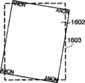
Figure 13 A illustrates the relation between the indicated not shielding area 1603 of print image zone 1602 before the amending image and dotted line.Figure 13 B illustrates print result.Under the control before amending image, whole print image prints unshieldedly.
Figure 13 C illustrates print image zone, image rotation/modification back 1602 and the relation between the shielding area 1603 not.Figure 13 D illustrates print result.Revise image to revise the distortion of scanner unit 24, therefore printer paper zone 1601 also is rotated for simplicity.Image rotates, and becomes and shield shape not match, so omitted.
In order to prevent the image omission, shielding control module 416 is revised not shielding area 1603 according to amending image, shown in Figure 13 E.Figure 13 F illustrates the not printout result during shielding area 1603 of modification (rotation).
Figure 14 A illustrates to 14D and changes the not principle of shielding area (shielding area).
Figure 14 A illustrates before the amending image print image zone 1602 and the relation between the shielding area 1603 not.Figure 14 B illustrates amended print image zone 1602.Shielding area is described to 12C as reference Figure 12 A, and is had rectangular shape by four register value Xa1, Xa2, Ya1 and Ya2 indication.
Figure 14 C illustrates the example that shielding area 1603 is not become rectangular shape according to amended image-region 1602.According to the relation between amended image and the drawing position, based on the result of calculation of registration error modified value computing unit 407, shielding area changes by pixel ground on main scanning direction and sub scanning direction independently.Because image is only revised on sub scanning direction among Figure 14 C, so Figure 14 C only illustrates the modification of shielding area on the sub scanning direction.
When the specify masks zone, value Xc1, the Xc2, Yc1 and the Yc2 that change four registers are to revise the size of rectangular shape.Figure 14 A only illustrates modification on the sub scanning direction to the example of 14D, and these values have following relationship:
Xc1=Xa1
Xc2=Xa2
Yc1=Ya1+Δac1
Yc2=Ya2
Wherein Δ ac1 is determined by the amending image amount, and the margin of error maximal value when revising with the sub scanning direction epigraph conforms to.
Figure 14 D illustrates when using the shape different with rectangle to specify not shielding area the not modification example of shielding area.In Figure 14 D, have only the regional conductively-closed of hacures indication, different with the modification of the not shielding area that utilizes rectangular shape among Figure 14 C.
According to this region specification method, 10 register parameters X1, Y1 specify position on main scanning direction and the sub scanning direction to X10 and Y10, and the point that each register is represented couples together to specify a zone.This processing is different with the designation method among Figure 14 A and the 14C.In this case, need be used to preserve the register of call parameter.
This method prevents the image omission more reliably, specifies not shielding area according to amending image, and does not export any undesired image.That is, this method can be set the shielding area (not shielding area) that shape is similar to the modification shape of image.
Although not shown in Figure 14 D, when revising image on main scanning direction, shielding area 1603 is not modified.
Figure 15 A and 15B are used for explanation according to present embodiment of the present invention, the not interference of shielding area in continuous printing.
Figure 15 A is illustrated in when not revising any image the image of page or leaf continuously.Distance is the distance between the print paper in printing continuously between the paper among Figure 15 A.Figure 15 B is illustrated in and revises image and the image of page or leaf during the shielding area modification.Distance between the print paper is very short, because image exports the cycle and the shielding area control cycle is very not long.Time corresponding to distance between paper is called " effectively time between paper ".
Short distance between each page (effectively between paper time) causes following problem: for example, the firmware that is used for printing control can not switch the processing in Fig. 1 coloured image forming device.In order to prevent this problem, always allow printout and need not to be not shielding area on a certain amending image amount control sub scanning direction, under this amending image amount situation, effectively the cycle becomes and equals or be shorter than the necessary schedule time of firmware handle between paper.
Note, only described monochromatic processing referring to figures 12A through 15B.When printing, each color is independently carried out identical control, with the shielding control of carries out image when preventing the image omission with C, M, Y and four kinds of colors of K.The time is calculated acquisition according to the time in the output cycle of having considered C, M, Y and K component between the effective paper shown in Figure 15 A and the 15B.
The processing of revising shielding area (not shielding area) with the amending image that is caused by the registration error correction is described with reference to Figure 16.
Figure 16 is that the shielding area (not shielding area) that illustrates according to present embodiment of the present invention is revised the process flow diagram of handling (shielding control).
In printing, the modified value of correcting process must be calculated before handling the view data that forms through image.The corrected Calculation that is used for calcuating correction value is finished once just enough in image forming portion 401.More specifically, based on each bar registration error description document information 413C, 413M, 413Y and 413K and each bar engine description document information 412, registration error correction-amount calculating 407C, 407M, 407Y and 407K calculate the correction of respective color pixel.In shielding control, shielding control module 416 changes shielding area according to correction.
In step S1, the exposure description document (each bar registration error description document information 413C, 413M, 413Y and 413K) measuring and write is read and obtained when factory's shipment to the host CPU (not shown) of image forming apparatus.
In step S2, registration error correction-amount calculating 407 is calculated the registration error correction based on the exposure description document.In step S3, registration error correction-amount calculating 407 is calculated the correction data (correction) that are used for changing according to the maximal value of the printer paper zone modified value that is used for printing the shielding area shape based on the registration error correction that calculates.The correction data of calculating shielding area are as being used to change the not correction data (correction) of shielding area shape.
In step S4, effectively distance is calculated based on the correction data that calculate between paper.In step S5, distance is determined by following between the effective paper that calculates.That is, determine that whether distance is greater than the predetermined value as the system design guarantee value between effective paper.If effectively distance handles advancing to step S6 greater than this predetermined value ("Yes" among the step S5) between paper, changing shielding area, and move on to print processing according to revising data.
If effectively distance is equal to or less than this predetermined value ("No" among the step S5) between paper, then shielding control is invalid, handles moving on to print processing.In this case, the storer of image forming apparatus (for example RAM) is set the invalid sign of expression shielding control.
Shielding control, the especially control in continuous printing are as shown in figure 15 explained in processing among Figure 16.Printing does not always require the processing among step S4, S5 and the S7.Promptly, when printing is only carried out one time, owing to do not cause the above-described problem that is used to print the switching firmware of control, thus image forming apparatus with the amending image that causes by the registration error correction only carry out shielding area (not shielding area) revise handle just enough.
To describe below according to the definite method in the level and smooth determining unit 806 of present embodiment.
In order to obtain high image quality, preferably in the precise image that forms by fine rule, do not carry out registration error correction less than a pixel, as Figure 17 A-1 to shown in the 17A-6.
On the contrary, wish to carry out registration correction less than a pixel to obtain high image quality to the isolated fine rule shown in the 17B-3 as Figure 17 B-1.
Below definite method allow easily to determine through less than the image of the registration correction of a pixel with there not be this image of process less than the registration correction of a pixel.
For example, the absolute value of being on duty is 128 or more for a long time, C1 is 1.C2 represents the scale-of-two absolute value of the difference of object pixel and back one pixel tonal value.Be similar to C1, the absolute value of being on duty is 128 or more for a long time, C2 is 1.C3 represents the OR value of C1 and C2.Number of pixels when C4 represents C3=1 in the window filter 73.
If C4 is 5 or more for a long time, level and smooth determining unit 806 determines that object pixels are the part of precise image, and does not carry out (forbidding) registration correction less than a pixel.This is always to present C4≤4 because form the pixel of isolated fine rule in the present embodiment, as shown in figure 19.According to this method, level and smooth determining unit 806 can easily be distinguished isolated fine rule and precise image.
The tone value of object pixel 72 is 0 among Figure 18, and the tone value of last pixel is 255, and the tone value of back one pixel is 0, and object pixel 72 presents C1=1, C2=0 and C3=1.In this case, C4=6 is because the window filter 73 of 1 pixel * 13 pixels (main scanning direction * sub scanning direction) has 6 pixels when C3=1.
Because C4 〉=5, level and smooth determining unit 806 determines that object pixel 72 is parts of precise image.Magenta tone value M0, yellow tone value Y0 carry out the processing identical with cyan with black tone value K0.At C2 and C3 the threshold value of image binarization is not limited to 128.Through should be suitably definite, and be not limited to C4 〉=5 according to picture quality less than the image of the registration correction of a pixel and the threshold value that not have to pass through less than between the image (its registration correction is forbidden) of the registration correction of a pixel.
As described above, according to this embodiment, when the registration error of electricity consumption submode correction print image, the shielding control module is according to the index word of image (print data), revises shielding area with the registration error correction of the target image of every kind of color.This processing can prevent when amending image and the interference of shielding area shape, and prevents the image omission when amending image.
The shielding control module can be set shielding area by shielding area is appointed as in the outside of rectangular area.The shielding control module also can be set at the zone that comprises the effective image-region before revising the zone (not shielding area) of not conductively-closed in the amended image.Present embodiment can be realized shielding control and prevent the image omission.
The shielding control module can be set shielding area by will the shape different with the rectangular area being appointed as shielding area.The shielding control module also can be set the zone (not shielding area) of a zone as not conductively-closed, and this zone is similar to the similar shape of the shape of amended image and comprises revises preceding effective image-region.Even image is revised significantly, present embodiment also can be realized shielding control and prevent the image omission.
When the shielding control module is gone up with when the predetermined correction of initial value or more amount are set shielding area at printer paper direction of transfer (main scanning direction), it makes shielding processing invalid and forbid shielding processing.Because the modification that one page was handled under shielding processing was only disturbed when printing multipage is under an embargo in handling, present embodiment can realize that page or leaf is printed and shielding processing continuously.
The shielding control module can be set the shielding area of respective color, and revises between each color the independently shape of shielding area according to the registration correction of respective color.Therefore, present embodiment can be handled the more slight change of shielding area shape.
Present embodiment is for example understood a kind of tandem coloured image forming device (graphics processing unit that wherein comprises developing cell is separately placed side by side along the print media direction of transfer), but the present invention is not limited to this.For example, the present invention also is applicable to the 1-drum-type image forming apparatus that uses developing cell, and wherein this developing cell constitutes by the developing cell of the integrated C of being used for, M, Y and four kinds of colors of K.1-drum-type image forming apparatus comprises at least one shielding control module, to carry out the shielding processing of this color when every kind of color image of transfer printing.
Present embodiment is for example understood a kind of coloured image forming device, but the present invention also is applicable to the monochrome image forming device.
Though invention has been described for reference example embodiment, should be appreciated that the present invention is not limited to disclosed exemplary embodiment.Should give the wideest explanation for the scope of following claim, to comprise all such modifications and equivalent configurations and function.
Claims (9)
1. image forming apparatus, this image forming apparatus have by use image-carrier image processing section, scanning and exposure image carrier exposing unit and the scan exposure by exposing unit is formed at electrostatic latent image visual developing cell on print media on the image-carrier, form image based on view data, this image forming apparatus comprises:
The image data storage apparatus that is used for storing image data;
The memory storage that is used for memory error amount information, on this margin of error information representation image-carrier in the exposure direction of scanning margin of error of exposure light sweep trace;
First modifier is used for based on the margin of error information correction view data that is stored in described memory storage; And
Second modifier is used for revising shielding area based on the index word of the view data of being revised by described first modifier, and wherein this shielding area is used to be limited in the outgoing position of visual image on the print media.
2. according to the equipment of claim 1, wherein said second modifier comprises
Save set is used to preserve positional information, and this positional information presentation graphs looks like to export initial permission position and image end of output permission position, allows the output of visual image on print media between these positions, and
Setting device, be used in the index word of described save set based on the view data of being revised by described first modifier, set image and export initial permission position and image end of output permission position, between these positions, be limited to the outgoing position of visual image on the print media.
3. according to the equipment of claim 1, wherein shielding area is the zone in addition, rectangular area that comprises the shape of view data.
4. according to the equipment of claim 1, wherein shielding area is the zone in addition, zone that comprises the shape of the view data of being revised by described first modifier and be similar to this shape.
5. according to the equipment of claim 1, wherein said second modifier comprises
Determine device, be used for determining whether the correction of revising shielding area based on the index word of the view data of being revised by described first modifier is not less than predetermined value, and
Whether determination device revises shielding area based on definite result's decision of described definite device.
6. according to the equipment of claim 1, wherein
Developing cell comprises and corresponding each developing cell of multiple color, and
Described second modifier is revised shielding area, and wherein this shielding area is used for limiting with one of multiple color by the outgoing position corresponding to developing cell visual image on print media of this color.
7. according to the equipment of claim 6, wherein
Each developing cell corresponding to multiple color is placed on the direction of transfer of print media side by side, and
Arrange described memory storage, described first modifier and described second modifier for each developing cell, wherein each described developing cell is separately corresponding to one of multiple color.
8. according to the equipment of claim 1, wherein
Developing cell constitutes by integrated each developing cell corresponding to multiple color, and
Described second modifier is revised shielding area, and wherein this shielding area is used for limiting with one of multiple color by the outgoing position corresponding to developing cell visual image on print media of this color.
9. method of controlling image forming apparatus, this image forming apparatus have by use image-carrier image processing section, scanning and exposure image carrier exposing unit and the scan exposure by exposing unit is formed at electrostatic latent image visual developing cell on print media on the image-carrier, form image based on view data, this image forming method comprises:
With the storing step of image data storage in the storage medium;
Obtain the obtaining step of the margin of error information that is stored in the storage medium, on this margin of error information representation image-carrier in the exposure direction of scanning margin of error of exposure light sweep trace;
First modify steps based on the margin of error information correction view data of obtaining in the obtaining step; With
Revise second modify steps of shielding area based on the index word of the view data that is modified in first modify steps, wherein this shielding area is used to be limited in the outgoing position of visual image on the print media.
Applications Claiming Priority (2)
| Application Number | Priority Date | Filing Date | Title |
|---|---|---|---|
| JP2005317118 | 2005-10-31 | ||
| JP2005317118A JP4850484B2 (en) | 2005-10-31 | 2005-10-31 | Image forming apparatus, control method therefor, and program |
Publications (2)
| Publication Number | Publication Date |
|---|---|
| CN1959549A CN1959549A (en) | 2007-05-09 |
| CN100462853C true CN100462853C (en) | 2009-02-18 |
Family
ID=37709457
Family Applications (1)
| Application Number | Title | Priority Date | Filing Date |
|---|---|---|---|
| CNB2006101429344A Expired - Fee Related CN100462853C (en) | 2005-10-31 | 2006-10-31 | Image forming apparatus and control method for the same |
Country Status (5)
| Country | Link |
|---|---|
| US (1) | US8253968B2 (en) |
| EP (1) | EP1780604B1 (en) |
| JP (1) | JP4850484B2 (en) |
| KR (1) | KR100861601B1 (en) |
| CN (1) | CN100462853C (en) |
Families Citing this family (13)
| Publication number | Priority date | Publication date | Assignee | Title |
|---|---|---|---|---|
| JP5074851B2 (en) * | 2007-07-31 | 2012-11-14 | キヤノン株式会社 | Image forming apparatus and image forming method |
| JP5144161B2 (en) * | 2007-07-31 | 2013-02-13 | キヤノン株式会社 | Color image forming apparatus and color image forming method |
| JP5006731B2 (en) * | 2007-07-31 | 2012-08-22 | キヤノン株式会社 | Image forming apparatus and image correction method |
| JP4950798B2 (en) * | 2007-07-31 | 2012-06-13 | キヤノン株式会社 | Image forming apparatus, control method therefor, and computer program |
| JP5450980B2 (en) * | 2008-05-08 | 2014-03-26 | キヤノン株式会社 | Image forming apparatus, control method thereof, program thereof, and storage medium |
| JP2010011429A (en) * | 2008-06-30 | 2010-01-14 | Canon Inc | Image processing apparatus and method of controlling the same |
| JP2010099885A (en) * | 2008-10-22 | 2010-05-06 | Canon Inc | Image forming device, image forming method, and image forming program |
| JP5241429B2 (en) * | 2008-10-24 | 2013-07-17 | キヤノン株式会社 | Image forming apparatus and control method thereof |
| JP5448600B2 (en) * | 2009-06-25 | 2014-03-19 | キヤノン株式会社 | Image forming apparatus |
| JP5594995B2 (en) * | 2009-09-09 | 2014-09-24 | キヤノン株式会社 | Image forming apparatus, image forming apparatus control method, and program |
| JP5471472B2 (en) * | 2010-01-13 | 2014-04-16 | セイコーエプソン株式会社 | Image forming apparatus |
| US20120105876A1 (en) * | 2010-10-31 | 2012-05-03 | Eyal Peleg | Color plane registration error correction |
| JP2021030598A (en) * | 2019-08-26 | 2021-03-01 | 京セラドキュメントソリューションズ株式会社 | Image formation apparatus, image formation method and image formation program |
Citations (3)
| Publication number | Priority date | Publication date | Assignee | Title |
|---|---|---|---|---|
| US5459586A (en) * | 1991-10-16 | 1995-10-17 | Fuji Xerox Co., Ltd. | Image processing system provided with image enchasing and synthesizing function |
| CN1471302A (en) * | 2002-07-27 | 2004-01-28 | ���ǵ�����ʽ���� | Method and apparatus for increasing digital image quality |
| JP2004170755A (en) * | 2002-11-21 | 2004-06-17 | Canon Inc | Color image forming apparatus |
Family Cites Families (22)
| Publication number | Priority date | Publication date | Assignee | Title |
|---|---|---|---|---|
| US4763165A (en) | 1985-03-18 | 1988-08-09 | Kabushiki Kaisha Toshiba | Image forming apparatus with image adding function |
| JPS61212863A (en) * | 1985-03-18 | 1986-09-20 | Toshiba Corp | Image forming device |
| JP2918268B2 (en) * | 1990-01-31 | 1999-07-12 | 富士通株式会社 | Color recording device |
| JPH07304211A (en) * | 1994-05-13 | 1995-11-21 | Oki Electric Ind Co Ltd | Method and device for color recording |
| JP3447907B2 (en) | 1996-02-07 | 2003-09-16 | 富士通株式会社 | Image forming device |
| JPH10235930A (en) * | 1997-02-21 | 1998-09-08 | Oki Electric Ind Co Ltd | Optical writing printer head and color printer employing it |
| EP0924648B1 (en) | 1997-12-18 | 2004-08-25 | Fuji Photo Film Co., Ltd. | Image processing apparatus and method |
| JPH11261805A (en) * | 1997-12-18 | 1999-09-24 | Fuji Photo Film Co Ltd | Image composition system and method, image composition device and client computer for constituting image composition system and image separation method |
| JP2000127501A (en) * | 1998-10-27 | 2000-05-09 | Matsushita Electric Ind Co Ltd | Image processor |
| JP2000347482A (en) | 1999-06-08 | 2000-12-15 | Canon Inc | Image forming device, its control method, and computer- readable storing medium storing the control program |
| JP2002116394A (en) | 2000-10-04 | 2002-04-19 | Canon Inc | Laser writing unit |
| US6493083B2 (en) | 2000-12-15 | 2002-12-10 | Xerox Corporation | Method for measuring color registration and determining registration error in marking platform |
| JP2002326395A (en) * | 2001-03-02 | 2002-11-12 | Fuji Photo Film Co Ltd | Exposure recording apparatus |
| KR100425310B1 (en) | 2001-11-23 | 2004-03-30 | 삼성전자주식회사 | A color registration compensating system for electrophotographic image forming apparatus and a compensating method using that system |
| JP2003241131A (en) | 2002-02-22 | 2003-08-27 | Canon Inc | Deflecting scanner and image forming device |
| JP2003266772A (en) | 2002-03-18 | 2003-09-24 | Fuji Xerox Co Ltd | Device and method for forming image |
| US6856338B2 (en) * | 2002-08-23 | 2005-02-15 | Canon Kabushiki Kaisha | Image forming apparatus |
| JP4487495B2 (en) | 2003-04-24 | 2010-06-23 | コニカミノルタホールディングス株式会社 | Inkjet printer |
| US7536125B2 (en) * | 2003-05-08 | 2009-05-19 | Sharp Kabushiki Kaisha | Image forming apparatus capable of suppressing developer waste |
| JP2005007621A (en) * | 2003-06-17 | 2005-01-13 | Canon Inc | Image formation device |
| JP4599827B2 (en) * | 2003-10-31 | 2010-12-15 | セイコーエプソン株式会社 | Tape printer and data processing method of tape printer |
| US20060039627A1 (en) * | 2004-08-21 | 2006-02-23 | Xerox Corporation | Real-time processing of grayscale image data |
-
2005
- 2005-10-31 JP JP2005317118A patent/JP4850484B2/en not_active Expired - Fee Related
-
2006
- 2006-10-30 KR KR1020060105695A patent/KR100861601B1/en not_active IP Right Cessation
- 2006-10-30 EP EP06123153.6A patent/EP1780604B1/en not_active Expired - Fee Related
- 2006-10-31 CN CNB2006101429344A patent/CN100462853C/en not_active Expired - Fee Related
- 2006-10-31 US US11/554,655 patent/US8253968B2/en active Active
Patent Citations (3)
| Publication number | Priority date | Publication date | Assignee | Title |
|---|---|---|---|---|
| US5459586A (en) * | 1991-10-16 | 1995-10-17 | Fuji Xerox Co., Ltd. | Image processing system provided with image enchasing and synthesizing function |
| CN1471302A (en) * | 2002-07-27 | 2004-01-28 | ���ǵ�����ʽ���� | Method and apparatus for increasing digital image quality |
| JP2004170755A (en) * | 2002-11-21 | 2004-06-17 | Canon Inc | Color image forming apparatus |
Also Published As
| Publication number | Publication date |
|---|---|
| JP4850484B2 (en) | 2012-01-11 |
| CN1959549A (en) | 2007-05-09 |
| EP1780604A3 (en) | 2011-06-29 |
| EP1780604B1 (en) | 2016-06-08 |
| US20070103728A1 (en) | 2007-05-10 |
| KR20070046742A (en) | 2007-05-03 |
| KR100861601B1 (en) | 2008-10-07 |
| US8253968B2 (en) | 2012-08-28 |
| EP1780604A2 (en) | 2007-05-02 |
| JP2007121923A (en) | 2007-05-17 |
Similar Documents
| Publication | Publication Date | Title |
|---|---|---|
| CN100462853C (en) | Image forming apparatus and control method for the same | |
| CN1885189B (en) | Color image forming apparatus | |
| US7864373B2 (en) | Method and system for toner reproduction curve linearization using least squares solution of monotone spline functions | |
| CN100561368C (en) | Imaging device | |
| CN100498570C (en) | Image forming apparatus and its control method | |
| CN102984431A (en) | Image forming apparatus and control method thereof | |
| CN102129190A (en) | Image forming apparatus and control method thereof | |
| US8005378B2 (en) | Method and system for improved control patch measurement in printing system | |
| US8879113B2 (en) | Image forming apparatus forming images in accordance with image forming conditions | |
| JP4612859B2 (en) | Image forming apparatus, control method therefor, and computer program | |
| JP4411339B2 (en) | Color image forming apparatus and control method thereof | |
| US8335026B2 (en) | Image forming apparatus and color shift correction method thereof | |
| JP2007163679A (en) | Image forming apparatus and control method and program therefor | |
| US8284227B2 (en) | Image forming apparatus and image forming method | |
| JP2023059744A (en) | Image inspection device, image inspection system, and program | |
| JP2007286509A (en) | Image forming apparatus | |
| JP2019113716A (en) | Image forming system | |
| JP7380148B2 (en) | Image forming apparatus and image forming operation adjustment method | |
| JP4939660B2 (en) | Image forming apparatus and control method thereof | |
| US9791817B2 (en) | Image forming apparatus using various kinds of correction processes | |
| JP2007316121A (en) | Color image forming apparatus, image forming method and program | |
| JP4757341B2 (en) | Image forming apparatus and control method thereof | |
| JP2009145847A (en) | Image forming apparatus | |
| JP2017198772A (en) | Image forming apparatus | |
| JP2009056703A (en) | Color image forming apparatus |
Legal Events
| Date | Code | Title | Description |
|---|---|---|---|
| C06 | Publication | ||
| PB01 | Publication | ||
| C10 | Entry into substantive examination | ||
| SE01 | Entry into force of request for substantive examination | ||
| C14 | Grant of patent or utility model | ||
| GR01 | Patent grant | ||
| CF01 | Termination of patent right due to non-payment of annual fee |
Granted publication date: 20090218 Termination date: 20181031 |
|
| CF01 | Termination of patent right due to non-payment of annual fee |