US8005378B2 - Method and system for improved control patch measurement in printing system - Google Patents
Method and system for improved control patch measurement in printing system Download PDFInfo
- Publication number
- US8005378B2 US8005378B2 US11/931,721 US93172107A US8005378B2 US 8005378 B2 US8005378 B2 US 8005378B2 US 93172107 A US93172107 A US 93172107A US 8005378 B2 US8005378 B2 US 8005378B2
- Authority
- US
- United States
- Prior art keywords
- photoreceptor
- control patch
- edge
- images
- customer image
- Prior art date
- Legal status (The legal status is an assumption and is not a legal conclusion. Google has not performed a legal analysis and makes no representation as to the accuracy of the status listed.)
- Expired - Fee Related, expires
Links
Images


Classifications
-
- G—PHYSICS
- G03—PHOTOGRAPHY; CINEMATOGRAPHY; ANALOGOUS TECHNIQUES USING WAVES OTHER THAN OPTICAL WAVES; ELECTROGRAPHY; HOLOGRAPHY
- G03G—ELECTROGRAPHY; ELECTROPHOTOGRAPHY; MAGNETOGRAPHY
- G03G15/00—Apparatus for electrographic processes using a charge pattern
- G03G15/50—Machine control of apparatus for electrographic processes using a charge pattern, e.g. regulating differents parts of the machine, multimode copiers, microprocessor control
- G03G15/5033—Machine control of apparatus for electrographic processes using a charge pattern, e.g. regulating differents parts of the machine, multimode copiers, microprocessor control by measuring the photoconductor characteristics, e.g. temperature, or the characteristics of an image on the photoconductor
- G03G15/5041—Detecting a toner image, e.g. density, toner coverage, using a test patch
Definitions
- the present exemplary embodiment relates to document processing systems and more particularly to improved process control patch measurement methods and print control systems.
- methods and systems are provided for print engine control in a document processing system.
- Electrophotographic laser printers, xerographic copiers, scanners, facsimile machines and other document processing systems are operable to print images and text onto printable media using imaging components operated according to print data.
- Electrostatic charge is initially distributed on an outer side surface of a photoreceptor or photographic member, which may be a rotating drum or a belt translated in a process direction in the printing engine.
- a customer image is optically projected on the charged photoreceptor surface using a raster image scanner leaving a latent image on the photoreceptor surface.
- the image is developed by the photoreceptor translating past a source of toner such that toner particles are drawn to the latent image via a carrier in order to create a visible image on the photoreceptor surface, and the toner image is then transferred to paper or other printable media and is fused to the media to create a printed document.
- the photoreceptor is discharged before the photoreceptor is again charged for printing of the next customer image.
- control patch is a predefined pattern that is created on the photoreceptor surface between adjacent customer images and is sensed or measured as the photoreceptor moves past a sensor. Different patches may be created for different colors, with each patch including light, dark, and medium areas, where more than one sensor may be used to measure the differently colored control patches created on the photoreceptor. Feedback information obtained from the measured control patch is used to adjust operating parameters of the printing system to maintain image quality, such as toner concentration, the magnitude of the charge on the photoreceptor, the amount of exposure from the scanner, etc.
- FIG. 12 shows a conventional process control patch implementation in which control patches 130 for each developer housing are created in an inter-document zone (IDZ) 122 between successive customer images 120 on a drum or belt type photoreceptor 110 a that moves along a process direction P.
- ITZ inter-document zone
- These control patches 130 are sensed with toner patch sensors (not shown) and actuators are adjusted to maintain a three-point tonal response curve (TRC).
- TRC three-point tonal response curve
- the inventors have appreciated that shortfalls in system performance, such as reload degradation, can cause undesirable interactions between the control patches and the customer images. In this situation, the presence of the customer image may cause distortion in the control patch image, and thereby lead to an error in the measured process control feedback for the print engine. Likewise, the presence of control patches in the IDZ may cause a distortion in the customer image.
- TRC three-point tonal response curve
- the present disclosure provides printing systems and control systems therefor, as well as methods for controlling customer image creation, in which process control patches are created on a moving photoreceptor in edge zones that are laterally offset from a lateral customer image boundary.
- image development system deficiencies with respect to customer images are decoupled from the process control or test patch images on the photoreceptor and vice versa, and accordingly the ability to control the print engine in closed loop fashion will not be adversely impacted by system performance degradation.
- One or more aspects of the present disclosure relate to a method for controlling a print engine in a printing system.
- the method involves creation of images between two lateral edges on a first side of a photoreceptor, where the images are created in predefined customer image areas separated along a process direction by an inter-document zone (IDZ), and where the customer image areas have a lateral boundary inward of the photoreceptor edge.
- the lateral image area boundary and the IDZ define an edge zone comprising a first portion laterally outside the customer image area between the lateral boundary and the photoreceptor edge alongside the customer image, and a second portion extending laterally outwardly of the lateral boundary through the IDZ.
- the method includes creating one or more process control patch images within the edge zone of the photoreceptor, sensing the patch image to generate measured control patch feedback information, and controlling the customer image creation in closed-loop fashion at least partially according to the measured control patch feedback information.
- control patch(es) may be located in either or both the first and/or second portions of the edge zone, and a given patch image may extend into both portions. Edge zones may be defined along both lateral edges of the photoreceptor with the customer image area therebetween, where control patches can be created in one or both such edge zones.
- the printing system includes a photoreceptor having customer image areas separated by inter-document zones along the process direction and having a first lateral boundary defining an edge zone laterally outward from the customer image area, as well as an imaging component, a sensor operative to sense the control patch images created in the edge zone, and a controller that receives feedback information from the sensor and controls the creation images in closed-loop fashion at least partially according to the measured control patch feedback information.
- FIG. 1 is a schematic system level diagram illustrating an exemplary document processing system with a control system for controlling a print engine using process control patch images in accordance with one or more aspects of the present disclosure
- FIG. 2 is a simplified partial side elevation schematic diagram illustrating further details of the printing and control components in the document processing system of FIG. 1 ;
- FIG. 3 is a partial top plan view illustrating a top surface of an exemplary photoreceptor structure in the printing system of FIGS. 1 and 2 including process control patch images created in second portions of an edge zone laterally outlying customer image areas on the top surface of the photoreceptor in accordance with various aspects of the present disclosure;
- FIG. 4 is an enlarged top plan view illustrating further details of the top photoreceptor surface including a succession of customer image areas to one side of a first lateral boundary and separated from one another along a process direction by an inter-document zone, as well as a first edge zone with a first portion laterally alongside the customer image area and a second portion extending laterally outwardly of the first lateral boundary through the inter-document zone;
- FIG. 5 is a partial top plan view illustrating a top surface of another exemplary photoreceptor structure in the printing system of FIGS. 1 and 2 including process control patch images created in the first portions of the edge zone outlying the customer image areas;
- FIG. 6 is a partial top plan view illustrating a top surface of another exemplary photoreceptor structure including a plurality of axially aligned different colored process control patch images created in the edge zone outlying the customer image areas;
- FIG. 7 is a partial top plan view illustrating a top surface of another exemplary photoreceptor structure including a plurality of different colored process control patch images created in staggered arrangements in the first portions of the edge zone;
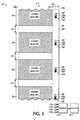
- FIG. 8 is a partial top plan view illustrating a top surface of another exemplary photoreceptor structure including a plurality of different colored process control patch images created in staggered arrangements in the first and second portions of the edge zone;
- FIG. 9 is a partial top plan view illustrating a top surface of another exemplary photoreceptor structure including a plurality of laterally aligned different colored process control patch images created in the second portions of the edge zone;
- FIG. 10 is a partial top plan view illustrating a top surface of another exemplary photoreceptor structure including a plurality of laterally aligned different colored process control patch images created in the first and second portions of the edge zone;
- FIG. 11 is a partial top plan view illustrating a top surface of another exemplary photoreceptor structure including process control patch images created in first and second edge zones laterally outlying the customer image areas;
- FIG. 12 is a partial top plan view illustrating a top surface of a conventional photoreceptor structure including process control patch images created in an inter-document zone between successive customer image areas.
- FIGS. 1 and 2 illustrate an exemplary document processing or printing system 10 in accordance with one or more aspects of the present disclosure.
- the printing system 10 can be any form of commercial printing apparatus, copier, printer, facsimile machine, or other system which may include a scanner or other input device 12 that scans an original document text and/or images to create an image comprising pixel values indicative of the colors and/or brightness of areas of the scanned original, and which has one or more marking engines or print engines 14 by which visual images, graphics, text, etc. are printed on a page or other printable medium, including xerographic, electro photographic, and other types of printing technology, wherein such components are not specifically illustrated in FIG. 1 to avoid obscuring the various alternate imaging features of the present disclosure.
- the print engine 14 may be any device or marking apparatus for applying an image from a digital front end (DFE) printer controller 102 to printable media (print media) such as a physical sheet of paper, plastic, or other suitable physical media substrate for images, whether precut or web fed, where the input device 12 , print engine 14 , and controller 102 are interconnected by wired and/or wireless links for transfer of electronic data therebetween, including but not limited to telephone lines, computer cables, ISDN lines, etc.
- the print engine 14 generally includes hardware and software elements employed in the creation of desired images by electrophotographic processes wherein suitable print engines 14 may also include ink-jet printers, such as solid ink printers, thermal head printers that are used in conjunction with heat sensitive paper, and other devices capable of printing an image on a printable media.
- the image input device 12 may include or be operatively coupled with conversion components for converting the image-bearing documents to image signals or pixels or such function may be assumed by the printing engine 14 .
- the printer controller 102 provides the output pixel data from memory to a print engine 14 that is fed with a print media sheets 22 from a feeding source 24 such as a paper feeder which can have one or more print media sources or paper trays 26 , 28 , 30 , 32 , each storing sheets of the same or different types of print media 22 on which the marking engine 14 can print.
- the exemplary print engine 14 includes an imaging component 44 and an associated fuser 48 , which may be of any suitable form or type, and may include further components which are omitted from the figure so as not to obscure the various aspects of the present disclosure.
- the printing engine 14 may include a photoconductive insulating member or photoreceptor 100 ( FIG. 2 ) which is charged to a uniform potential via a corotron 114 and exposed to a light image of an original document to be reproduced via an imaging laser 116 under control of a controller 104 of the DFE 102 .
- the exposure discharges the photoconductive insulating surface of the photoreceptor 100 in exposed or background areas and creates an electrostatic latent image on the photoreceptor 100 corresponding to image areas of the original document.
- the electrostatic latent image on the photoreceptor 100 is made visible by developing the image with an imaging material such as a developing powder comprising toner particles via a development unit 118 , and the customer image is then transferred to the print media 22 and permanently affixed thereto in the fusing process.
- an imaging material such as a developing powder comprising toner particles via a development unit 118 .
- successive latent images corresponding to different colors can be formed on the photoreceptor 100 and developed with a respective toner of a complementary color, with each color toner image being successively transferred to the paper sheet 22 in superimposed registration with the prior toner image to create a multi-layered toner image on the printed media 22 , and where the superimposed images may be fused contemporaneously, in a single fusing process.
- the fuser 48 ( FIG. 1 ) receives the imaged print media from the image-forming component and fixes the toner image transferred to the surface of the print media 22 , where the fuser 48 can be of any suitable type, and may include fusers which apply heat or both heat and pressure to an image.
- Printed media from the printing engine 14 is delivered to a finisher 36 including one or more finishing output destinations 38 , 40 , 42 such as trays, stackers, pans, etc.
- the document processing system 10 is operative to perform these scanning and printing tasks in the execution of print jobs, which can include printing selected text, line graphics, images, machine ink character recognition (MICR) notation, etc., on either or both of the front and back sides or pages of one or more media sheets 22 .
- An original document or image or print job or jobs can be supplied to the printing system 10 in various ways.
- the built-in optical scanner 12 may be used to scan an original document such as book pages, a stack of printed pages, or so forth, to create a digital image of the scanned document that is reproduced by printing operations performed by the printing system 10 via the print engine 14 .
- the print jobs can be electronically delivered to the system controller 102 via a network or other means, for instance, whereby a network user can print a document from word processing software running on a network computer, thereby generating an input print job.
- a print media transporting system or network or highway 60 of the document processing system 10 links the print media source 24 , the print engine 14 and a finisher 36 via a network of flexible automatically feeding and collecting drive members, such as pairs of rollers 62 , spherical nips, air jets, or the like, along with various motors for the drive members, belts, guide rods, frames, etc. (not shown), which, in combination with the drive members, serve to convey the print media along selected pathways at selected speeds.
- drive members such as pairs of rollers 62 , spherical nips, air jets, or the like
- print media 22 is delivered from the source 24 to the print engine 14 via a pathway 64 common to the input trays 26 , 28 , 30 , 32 , and is printed by the imaging component 44 and fused by the fuser 48 , with a pathway 68 from the print engine 14 merging into a pathway 74 which conveys the printed media to the finisher 36 , where the pathways 64 , 68 , 74 of the network 60 may include inverters, reverters, interposers, bypass pathways, and the like as known in the art.
- the print engine 14 may be configured for duplex or simplex printing and a single sheet of paper 22 may be marked by two or more print engines 14 or may be marked a plurality of times by the same marking engine 14 , for instance, using internal duplex pathways.
- the exemplary document processor 10 comprises a control system including a controller 104 and one or more sensors, such as toner patch sensors 110 providing feedback 112 to the controller with respect to process control or test patch images created on the photoreceptor 100 .
- the illustrated photoreceptor is a belt type structure including a top side 100 T and a bottom side 100 B.
- the DFE controller 104 operates the imaging components 114 , 116 , and 118 to create customer images on the first or top surface 100 T as the photoreceptor 100 is translated along the process direction P.
- the first or top side 100 T of the photoreceptor 100 has first and second lateral edges 100 a and 100 b generally parallel to the process direction P and includes predefined customer image areas 120 with successive customer image areas 120 separated from one another along the process direction P by inter-document zones (IDZs) 122 .
- the individual customer image areas 120 have a first lateral boundary 124 laterally inward of the first photoreceptor edge 100 a that defines a first edge zone 126 with a first edge zone portion 126 P 1 ( FIG. 4 ) laterally outside the customer image area 120 between the first lateral boundary 124 and the first photoreceptor edge 100 a and a second portion 126 P 2 extending laterally outwardly of the first lateral boundary 124 through the IDZ 122 .
- the controller 104 causes the imaging components 114 , 116 , and 118 ( FIG. 2 ) to create at least one process control patch image 130 ( FIG. 3 ) within the first edge zone 126 of the photoreceptor top side 100 T, where the example of FIG. 3 includes process control patch images 130 created in second portions 126 P 2 of the first edge zone 126 laterally outlying (e.g., alongside) the customer image areas 120 .
- the individual patch images 130 include a light portion 131 l , a medium portion 131 m , and a dark portion 131 d , where successive patch images 130 may be of different colors, such as cyan (c), magenta (m), yellow (y), and black (k).
- Other implementations are possible in which individual control patch images 130 only include one portion (e.g., light, medium, or dark).
- corresponding toner patch sensors 110 c , 110 m , 110 y , and 110 k are located along the edge zone path of the translating photoreceptor 100 so as to allow sensing of the process control patch images 130 as they move along the process direction P.
- the measurements of the process control patch images 130 are provided from the sensor(s) 130 as feedback 112 signals or data to the controller 104 of the DFE 102 for use in adjusting the operational parameters of the imaging components used in creating customer images in the customer image areas 120 of the photoreceptor 100 in closed loop fashion.
- control patches 130 are moved beyond the lateral extent of the customer image areas 120 so as to decouple image development system deficiencies with respect to customer images from the process control patch images.
- the controller 104 receives the patch sensor feedback 112 and controls the creation of the customer images in closed-loop fashion at least partially according to the measured control patch feedback information 112 .
- FIG. 5 illustrates another example in which the controller 104 causes creation of process control patch images in the first portion 126 P 1 of the first edge zone 126 .
- a single test patch image 130 with light, medium, and dark portions 131 l , 131 m , and 131 d , respectively, is created in the first portion 126 P 1 alongside each customer image area 120 with successive control patch images being of different colors, such as cyan (patch 130 c ), magenta (patch 130 m ), yellow ( 130 y ), and black (patch 130 k ).
- Other embodiments are possible in which a control patch 130 is provided alongside every other customer image area 120 , and other spacings may be provided in alternate implementations within the scope of the present disclosure.
- FIG. 6 illustrates yet another exemplary embodiment in which multiple control patch images 130 are created alongside each customer image area 120 , wherein at least two patches 130 are in a given first edge zone portion 126 P 1 .
- different colored process control patch images 130 c , 130 m , 130 y , and 130 k are created in the first portions 126 P 1 alongside each customer image area 120 , although not a strict requirement of the broader aspects of the present disclosure.
- the differently colored test patches 130 are axially aligned with one another in the first portions 126 P 1 of the first edge zone 126 and the corresponding toner patch sensors 110 are also axially aligned relative to the process direction P although alternate implementations are possible without such axial alignment.
- FIG. 7 illustrates another possible implementation, in which multiple control patch images 130 are again created alongside each customer image area 120 in one or more of the first edge zone portions 126 P 1 , with different colored process control patch images 130 c , 130 m , 130 y , and 130 k created in the first portions 126 P 1 .
- the different colored process control patch images 130 are created in staggered arrangements in the first portions 126 P 1 of the edge zone 126 with four differently colored patch images 130 c , 130 m , 130 y , and 130 k within each of the edge zone first portions.
- FIG. 8 illustrates still another embodiment including a plurality of different colored process control patch images 130 c , 130 m , 130 y , and 130 k created in staggered arrangements in the first and second portions of the edge zone.
- different control patch images 130 can be created in the first and second edge zone portions 126 P 1 and 126 P 2 and individual patch images 130 can straddle the two portions 126 P 1 and 126 P 2 , wherein all such variant implementations are possible within the scope of the present disclosure in which at least one patch image 130 is created in the edge zone 126 laterally outlying the boundary 124 of the customer image areas 120 .
- FIG. 9 shows yet another exemplary photoreceptor structure 100 including a plurality of different colored process control patch images 130 c , 130 m , 130 y , and 130 k that are laterally aligned with respect to one another in a direction perpendicular to the process direction P, where the patches 130 in this embodiment are created in the second portions 126 P 2 of the edge zone 126 along the first side 100 a of the photoreceptor 100 .
- the control system provides for location of the corresponding toner patch sensors 110 c , 110 m , 110 y , 110 k at different lateral distances from the edge 100 a so as to be able to sense the corresponding test patch images 130 as the photoreceptor structure 100 is translated along the process direction P.
- the spacing of successive process control patches 130 or groups thereof need not be the same as the spacing between successive customer image areas 120 .
- a plurality of laterally aligned different colored process control patch images 130 are created in the first and second portions of the edge zone 126 , where the spacing 140 between successive customer image areas 120 is different than the spacing 142 between successive groups of process control patch images 130 .
- the customer image areas 120 may have a second lateral boundary 124 a laterally inward of the second photoreceptor edge 100 b to thus define a second edge zone 126 a that itself has a first portion laterally outside the customer image area 120 between the second lateral boundary 124 a and the second photoreceptor edge 100 b , as well as a second portion extending laterally outwardly of the second lateral boundary 124 a through the inter-document zone 122 .
- FIG. 11 illustrates yet another exemplary photoreceptor structure 100 that includes process control patch images 130 created in such first and second edge zones 126 and 126 a , respectively, each laterally outlying the customer image areas 120 , where the edge zones 126 , 126 a may, but need not, be of the same width.
- this approach essentially decouples any system performance issues with respect to the process control patch images 130 and the images of the customer image areas 120 .
- the controller 104 causes the imaging component(s) to create another process control patch image 130 within the second edge zone 126 a and corresponding sensors are provided along each edge zone 126 , 126 a of the photoreceptor structure 100 .
- FIG. 11 illustrates yet another exemplary photoreceptor structure 100 that includes process control patch images 130 created in such first and second edge zones 126 and 126 a , respectively, each laterally outlying the customer image areas 120 , where the edge zones 126 , 126 a may, but need not, be of the same width.
- a first set of cyan, magenta, yellow, and black sensors 110 c 1 , 110 m 1 , 110 y 1 , and 110 k 1 are provided to sense control patch images 130 of the first edge zone 126
- a second set of cyan, magenta, yellow, and black sensors 110 c 2 , 110 m 2 , 110 y 2 , and 110 k 2 are provided to sense control patch images 130 of the second edge zone 126 a.
Landscapes
- Engineering & Computer Science (AREA)
- Microelectronics & Electronic Packaging (AREA)
- Physics & Mathematics (AREA)
- General Physics & Mathematics (AREA)
- Control Or Security For Electrophotography (AREA)
Abstract
Description
Claims (5)
Priority Applications (1)
| Application Number | Priority Date | Filing Date | Title |
|---|---|---|---|
| US11/931,721 US8005378B2 (en) | 2007-10-31 | 2007-10-31 | Method and system for improved control patch measurement in printing system |
Applications Claiming Priority (1)
| Application Number | Priority Date | Filing Date | Title |
|---|---|---|---|
| US11/931,721 US8005378B2 (en) | 2007-10-31 | 2007-10-31 | Method and system for improved control patch measurement in printing system |
Publications (2)
| Publication Number | Publication Date |
|---|---|
| US20090110420A1 US20090110420A1 (en) | 2009-04-30 |
| US8005378B2 true US8005378B2 (en) | 2011-08-23 |
Family
ID=40582999
Family Applications (1)
| Application Number | Title | Priority Date | Filing Date |
|---|---|---|---|
| US11/931,721 Expired - Fee Related US8005378B2 (en) | 2007-10-31 | 2007-10-31 | Method and system for improved control patch measurement in printing system |
Country Status (1)
| Country | Link |
|---|---|
| US (1) | US8005378B2 (en) |
Cited By (3)
| Publication number | Priority date | Publication date | Assignee | Title |
|---|---|---|---|---|
| US11528386B1 (en) | 2021-08-30 | 2022-12-13 | Xerox Corporation | Printing color separation and fiducials on substrates in an inkjet printer to register and print remaning color separations |
| US11613116B1 (en) | 2021-10-01 | 2023-03-28 | Xerox Corporation | System and method for printing color images on substrates in an inkjet printer |
| US11912045B2 (en) | 2022-03-24 | 2024-02-27 | Xerox Corporation | System and method for printing color images on substrates in an inkjet printer |
Families Citing this family (6)
| Publication number | Priority date | Publication date | Assignee | Title |
|---|---|---|---|---|
| JP5320430B2 (en) * | 2010-06-02 | 2013-10-23 | パナソニック株式会社 | Coating method and organic EL display manufacturing method |
| JP5893377B2 (en) * | 2011-12-09 | 2016-03-23 | キヤノン株式会社 | Image forming apparatus |
| JP6107775B2 (en) * | 2014-09-18 | 2017-04-05 | コニカミノルタ株式会社 | Image forming apparatus, image forming system, and image forming control method |
| JP6288005B2 (en) * | 2015-08-18 | 2018-03-07 | コニカミノルタ株式会社 | Image forming apparatus, image forming management apparatus, and image forming method |
| JP6278033B2 (en) * | 2015-11-18 | 2018-02-14 | コニカミノルタ株式会社 | Image forming apparatus and program |
| JP2017173625A (en) * | 2016-03-24 | 2017-09-28 | コニカミノルタ株式会社 | Image formation device |
Citations (15)
| Publication number | Priority date | Publication date | Assignee | Title |
|---|---|---|---|---|
| US4949105A (en) | 1989-08-16 | 1990-08-14 | Eastman Kodak Company | Process control patch generator |
| US5227270A (en) | 1991-09-05 | 1993-07-13 | Xerox Corporation | Esv readings of toner test patches for adjusting ird readings of developed test patches |
| US5416563A (en) | 1994-02-04 | 1995-05-16 | Xerox Corporation | Xerographic process control by adjusting photoreceptor voltages by photoreceptor segments |
| US5463455A (en) | 1993-12-06 | 1995-10-31 | Xerox Corporation | Method and apparatus for adaptive cleaner blade lubrication |
| US5826139A (en) | 1996-09-30 | 1998-10-20 | Xerox Corporation | Method and apparatus for controlling the sequence, size and position of an image control patch |
| US5995775A (en) | 1998-03-05 | 1999-11-30 | Xerox Corporation | ROS pixel size growth detector |
| US6198490B1 (en) * | 1998-10-29 | 2001-03-06 | Samsung Electronics Co., Ltd. | Printer and method of correcting color registration error thereof |
| US6204869B1 (en) | 1998-05-04 | 2001-03-20 | Xerox Corporation | Control system for test patch area exposure in a printing machine |
| US20030031483A1 (en) * | 2001-08-13 | 2003-02-13 | Kazuyoshi Kondoh | Image forming apparatus |
| US6526240B1 (en) | 2001-08-28 | 2003-02-25 | Xerox Corporation | Versatile system for creating test images in a digital printing apparatus |
| US6697582B1 (en) | 2003-01-15 | 2004-02-24 | Xerox Corporation | Dynamic control patches for better TRC control |
| US20060001911A1 (en) | 2004-06-21 | 2006-01-05 | Xerox Corporation | Closed-loop compensation of streaks by ros intensity variation |
| US20060188298A1 (en) * | 2005-02-22 | 2006-08-24 | Fuji Xerox Co., Ltd. | Image formation device |
| US20080025742A1 (en) * | 2006-05-24 | 2008-01-31 | Shinji Kato | Image forming apparatus and image forming method |
| US20080075492A1 (en) * | 2006-09-26 | 2008-03-27 | Xerox Corporation | Color sensor to measure single separation, mixed color or ioi patches |
-
2007
- 2007-10-31 US US11/931,721 patent/US8005378B2/en not_active Expired - Fee Related
Patent Citations (15)
| Publication number | Priority date | Publication date | Assignee | Title |
|---|---|---|---|---|
| US4949105A (en) | 1989-08-16 | 1990-08-14 | Eastman Kodak Company | Process control patch generator |
| US5227270A (en) | 1991-09-05 | 1993-07-13 | Xerox Corporation | Esv readings of toner test patches for adjusting ird readings of developed test patches |
| US5463455A (en) | 1993-12-06 | 1995-10-31 | Xerox Corporation | Method and apparatus for adaptive cleaner blade lubrication |
| US5416563A (en) | 1994-02-04 | 1995-05-16 | Xerox Corporation | Xerographic process control by adjusting photoreceptor voltages by photoreceptor segments |
| US5826139A (en) | 1996-09-30 | 1998-10-20 | Xerox Corporation | Method and apparatus for controlling the sequence, size and position of an image control patch |
| US5995775A (en) | 1998-03-05 | 1999-11-30 | Xerox Corporation | ROS pixel size growth detector |
| US6204869B1 (en) | 1998-05-04 | 2001-03-20 | Xerox Corporation | Control system for test patch area exposure in a printing machine |
| US6198490B1 (en) * | 1998-10-29 | 2001-03-06 | Samsung Electronics Co., Ltd. | Printer and method of correcting color registration error thereof |
| US20030031483A1 (en) * | 2001-08-13 | 2003-02-13 | Kazuyoshi Kondoh | Image forming apparatus |
| US6526240B1 (en) | 2001-08-28 | 2003-02-25 | Xerox Corporation | Versatile system for creating test images in a digital printing apparatus |
| US6697582B1 (en) | 2003-01-15 | 2004-02-24 | Xerox Corporation | Dynamic control patches for better TRC control |
| US20060001911A1 (en) | 2004-06-21 | 2006-01-05 | Xerox Corporation | Closed-loop compensation of streaks by ros intensity variation |
| US20060188298A1 (en) * | 2005-02-22 | 2006-08-24 | Fuji Xerox Co., Ltd. | Image formation device |
| US20080025742A1 (en) * | 2006-05-24 | 2008-01-31 | Shinji Kato | Image forming apparatus and image forming method |
| US20080075492A1 (en) * | 2006-09-26 | 2008-03-27 | Xerox Corporation | Color sensor to measure single separation, mixed color or ioi patches |
Cited By (3)
| Publication number | Priority date | Publication date | Assignee | Title |
|---|---|---|---|---|
| US11528386B1 (en) | 2021-08-30 | 2022-12-13 | Xerox Corporation | Printing color separation and fiducials on substrates in an inkjet printer to register and print remaning color separations |
| US11613116B1 (en) | 2021-10-01 | 2023-03-28 | Xerox Corporation | System and method for printing color images on substrates in an inkjet printer |
| US11912045B2 (en) | 2022-03-24 | 2024-02-27 | Xerox Corporation | System and method for printing color images on substrates in an inkjet printer |
Also Published As
| Publication number | Publication date |
|---|---|
| US20090110420A1 (en) | 2009-04-30 |
Similar Documents
| Publication | Publication Date | Title |
|---|---|---|
| US8005378B2 (en) | Method and system for improved control patch measurement in printing system | |
| US7672634B2 (en) | Addressable fusing for an integrated printing system | |
| US7310108B2 (en) | Printing system | |
| US7305198B2 (en) | Printing system | |
| US7257358B2 (en) | Method and apparatus for detecting registration errors in an image forming device | |
| JP6270138B2 (en) | Image forming apparatus | |
| US8204416B2 (en) | Method and apparatus for measuring color-to-color registration | |
| CN100561368C (en) | Imaging device | |
| JP2012527642A (en) | Image scaling in dual engine systems | |
| JP6307961B2 (en) | Image forming apparatus | |
| US7263301B2 (en) | Inline purge capability (purge while run) to improve system productivity during low area coverage runs | |
| US7922288B2 (en) | Printing system | |
| US10031705B2 (en) | Image forming apparatus and image forming method with real time image quality adjustment function | |
| JP7495830B2 (en) | Image processing device and image forming device | |
| US7903985B2 (en) | Image forming system having wet and dry imaging parts | |
| JP5146238B2 (en) | Image forming apparatus | |
| CN101030058B (en) | image forming device | |
| JP2006126281A (en) | Image forming apparatus | |
| JP2011154090A (en) | Image forming apparatus | |
| US9915905B2 (en) | Image forming apparatus | |
| US20250328104A1 (en) | Image forming apparatus | |
| US12556641B2 (en) | Image processing apparatus and image forming apparatus | |
| JP2021021911A (en) | Image forming apparatus | |
| JP6882925B2 (en) | Image forming device, control program and control method | |
| US10375254B2 (en) | Image forming apparatus and recording medium |
Legal Events
| Date | Code | Title | Description |
|---|---|---|---|
| AS | Assignment |
Owner name: XEROX CORPORATION, CONNECTICUT Free format text: ASSIGNMENT OF ASSIGNORS INTEREST;ASSIGNORS:SHEFLIN, JOSEPH;LESTRANGE, JACK;REEL/FRAME:020046/0994 Effective date: 20071030 |
|
| FEPP | Fee payment procedure |
Free format text: PAYOR NUMBER ASSIGNED (ORIGINAL EVENT CODE: ASPN); ENTITY STATUS OF PATENT OWNER: LARGE ENTITY |
|
| ZAAA | Notice of allowance and fees due |
Free format text: ORIGINAL CODE: NOA |
|
| ZAAB | Notice of allowance mailed |
Free format text: ORIGINAL CODE: MN/=. |
|
| STCF | Information on status: patent grant |
Free format text: PATENTED CASE |
|
| FPAY | Fee payment |
Year of fee payment: 4 |
|
| MAFP | Maintenance fee payment |
Free format text: PAYMENT OF MAINTENANCE FEE, 8TH YEAR, LARGE ENTITY (ORIGINAL EVENT CODE: M1552); ENTITY STATUS OF PATENT OWNER: LARGE ENTITY Year of fee payment: 8 |
|
| AS | Assignment |
Owner name: CITIBANK, N.A., AS AGENT, DELAWARE Free format text: SECURITY INTEREST;ASSIGNOR:XEROX CORPORATION;REEL/FRAME:062740/0214 Effective date: 20221107 |
|
| FEPP | Fee payment procedure |
Free format text: MAINTENANCE FEE REMINDER MAILED (ORIGINAL EVENT CODE: REM.); ENTITY STATUS OF PATENT OWNER: LARGE ENTITY |
|
| AS | Assignment |
Owner name: XEROX CORPORATION, CONNECTICUT Free format text: RELEASE OF SECURITY INTEREST IN PATENTS AT R/F 062740/0214;ASSIGNOR:CITIBANK, N.A., AS AGENT;REEL/FRAME:063694/0122 Effective date: 20230517 |
|
| AS | Assignment |
Owner name: CITIBANK, N.A., AS COLLATERAL AGENT, NEW YORK Free format text: SECURITY INTEREST;ASSIGNOR:XEROX CORPORATION;REEL/FRAME:064760/0389 Effective date: 20230621 |
|
| LAPS | Lapse for failure to pay maintenance fees |
Free format text: PATENT EXPIRED FOR FAILURE TO PAY MAINTENANCE FEES (ORIGINAL EVENT CODE: EXP.); ENTITY STATUS OF PATENT OWNER: LARGE ENTITY |
|
| STCH | Information on status: patent discontinuation |
Free format text: PATENT EXPIRED DUE TO NONPAYMENT OF MAINTENANCE FEES UNDER 37 CFR 1.362 |
|
| FP | Lapsed due to failure to pay maintenance fee |
Effective date: 20230823 |
|
| AS | Assignment |
Owner name: XEROX CORPORATION, CONNECTICUT Free format text: TERMINATION AND RELEASE OF SECURITY INTEREST IN PATENTS RECORDED AT RF 064760/0389;ASSIGNOR:CITIBANK, N.A., AS COLLATERAL AGENT;REEL/FRAME:068261/0001 Effective date: 20240206 |