CN100496859C - Laser processing method - Google Patents
Laser processing method Download PDFInfo
- Publication number
- CN100496859C CN100496859C CNB2005800257931A CN200580025793A CN100496859C CN 100496859 C CN100496859 C CN 100496859C CN B2005800257931 A CNB2005800257931 A CN B2005800257931A CN 200580025793 A CN200580025793 A CN 200580025793A CN 100496859 C CN100496859 C CN 100496859C
- Authority
- CN
- China
- Prior art keywords
- modification area
- object thing
- processing object
- laser
- area
- Prior art date
- Legal status (The legal status is an assumption and is not a legal conclusion. Google has not performed a legal analysis and makes no representation as to the accuracy of the status listed.)
- Active
Links
Images


Classifications
-
- B—PERFORMING OPERATIONS; TRANSPORTING
- B23—MACHINE TOOLS; METAL-WORKING NOT OTHERWISE PROVIDED FOR
- B23K—SOLDERING OR UNSOLDERING; WELDING; CLADDING OR PLATING BY SOLDERING OR WELDING; CUTTING BY APPLYING HEAT LOCALLY, e.g. FLAME CUTTING; WORKING BY LASER BEAM
- B23K26/00—Working by laser beam, e.g. welding, cutting or boring
- B23K26/36—Removing material
- B23K26/38—Removing material by boring or cutting
-
- B—PERFORMING OPERATIONS; TRANSPORTING
- B23—MACHINE TOOLS; METAL-WORKING NOT OTHERWISE PROVIDED FOR
- B23K—SOLDERING OR UNSOLDERING; WELDING; CLADDING OR PLATING BY SOLDERING OR WELDING; CUTTING BY APPLYING HEAT LOCALLY, e.g. FLAME CUTTING; WORKING BY LASER BEAM
- B23K26/00—Working by laser beam, e.g. welding, cutting or boring
- B23K26/02—Positioning or observing the workpiece, e.g. with respect to the point of impact; Aligning, aiming or focusing the laser beam
- B23K26/06—Shaping the laser beam, e.g. by masks or multi-focusing
-
- B—PERFORMING OPERATIONS; TRANSPORTING
- B23—MACHINE TOOLS; METAL-WORKING NOT OTHERWISE PROVIDED FOR
- B23K—SOLDERING OR UNSOLDERING; WELDING; CLADDING OR PLATING BY SOLDERING OR WELDING; CUTTING BY APPLYING HEAT LOCALLY, e.g. FLAME CUTTING; WORKING BY LASER BEAM
- B23K26/00—Working by laser beam, e.g. welding, cutting or boring
- B23K26/36—Removing material
- B23K26/40—Removing material taking account of the properties of the material involved
-
- B—PERFORMING OPERATIONS; TRANSPORTING
- B23—MACHINE TOOLS; METAL-WORKING NOT OTHERWISE PROVIDED FOR
- B23K—SOLDERING OR UNSOLDERING; WELDING; CLADDING OR PLATING BY SOLDERING OR WELDING; CUTTING BY APPLYING HEAT LOCALLY, e.g. FLAME CUTTING; WORKING BY LASER BEAM
- B23K26/00—Working by laser beam, e.g. welding, cutting or boring
- B23K26/50—Working by transmitting the laser beam through or within the workpiece
- B23K26/53—Working by transmitting the laser beam through or within the workpiece for modifying or reforming the material inside the workpiece, e.g. for producing break initiation cracks
-
- B—PERFORMING OPERATIONS; TRANSPORTING
- B23—MACHINE TOOLS; METAL-WORKING NOT OTHERWISE PROVIDED FOR
- B23K—SOLDERING OR UNSOLDERING; WELDING; CLADDING OR PLATING BY SOLDERING OR WELDING; CUTTING BY APPLYING HEAT LOCALLY, e.g. FLAME CUTTING; WORKING BY LASER BEAM
- B23K2101/00—Articles made by soldering, welding or cutting
- B23K2101/36—Electric or electronic devices
- B23K2101/40—Semiconductor devices
-
- B—PERFORMING OPERATIONS; TRANSPORTING
- B23—MACHINE TOOLS; METAL-WORKING NOT OTHERWISE PROVIDED FOR
- B23K—SOLDERING OR UNSOLDERING; WELDING; CLADDING OR PLATING BY SOLDERING OR WELDING; CUTTING BY APPLYING HEAT LOCALLY, e.g. FLAME CUTTING; WORKING BY LASER BEAM
- B23K2103/00—Materials to be soldered, welded or cut
- B23K2103/50—Inorganic material, e.g. metals, not provided for in B23K2103/02 – B23K2103/26
Landscapes
- Engineering & Computer Science (AREA)
- Optics & Photonics (AREA)
- Physics & Mathematics (AREA)
- Mechanical Engineering (AREA)
- Plasma & Fusion (AREA)
- Chemical Kinetics & Catalysis (AREA)
- Oil, Petroleum & Natural Gas (AREA)
- General Chemical & Material Sciences (AREA)
- Chemical & Material Sciences (AREA)
- Laser Beam Processing (AREA)
- Dicing (AREA)
- Processing Of Stones Or Stones Resemblance Materials (AREA)
- Laser Surgery Devices (AREA)
Abstract
A laser processing method enabling highly accurate cutting of an object to be processed. In the laser processing method, laser light (L) is irradiated with a light concentration point (P) set at the inside of a plate-like object (1) to be processed. First, a first reforming region (71) as a start point of cutting is formed along a first to-be-cut line (5a) of the object (1). Then, a second reforming region (72) as a start point of cutting is formed along a second to-be-cut line (5b), intersecting with the to-be-cut line (5a), so as to intersects with at least a portion of the reforming region (71). After that, a fourth reforming region (73) as a start point of cutting is formed along the to-be-cut line (5b). Then, a third reforming region (74) as a start point of cutting is formed along the to-be-cut line (5a) so as to intersect with at least a portion of the reforming region (73), the third reforming region (74) being formed between the reforming region (71) and an incident surface (1a) of the object (1), into which incident surface (1a) the laser light (L) enters.
Description
Technical field
The present invention relates to the laser processing that uses in order to cut off tabular processing object thing.
Background technology
At existing this technical elements, following laser processing is arranged, the inside of the processing object thing by making focus point alignment wafer shape is with irradiating laser, make along the modification area that cuts off preset lines and form multiple row in the inside of processing object thing, and with the starting point (for example, with reference to patent documentation 1) of its modification area as cut-out.
Patent documentation 1: 2002-No. 205180 communiques of TOHKEMY
Use laser processing as described above that tabular processing object thing is cut under the cancellate situation in desire, for example, shown in Figure 20 (A) and Figure 20 (B), form modification area in the inside of processing object thing.Figure 20 (A) and Figure 20 (B) are the ideographs that is used to illustrate an example of the order when the inside of processing object thing 101 forms modification area 171,172, and Figure 21 is the sectional view along the XXI-XXI line of the processing object thing shown in Figure 20 (B).
Modification area the 171, the 172nd forms in the following order.At first, shown in Figure 20 (A), the irradiating laser 100L by processing object thing 101 inside that make focus point alignment thickness 100d will be formed on the inside of processing object thing 101 along the modification area 171 that cuts off preset lines 105a.Secondly, shown in Figure 20 (B),, make along being formed on the inside of processing object thing 101 with the modification area 172 that cuts off the cut-out preset lines 105b that preset lines 105a intersects by making inside that focus point aims at processing object thing 101 irradiating laser 100L again.Modification area 171,172 is made of the modification area of the multiple row that the thickness direction along processing object thing 101 is set up in parallel, and the modification area of these multiple rows is formed successively from the plane of incidence 101a of distance laser 100L position far away.
After forming modification area 171,172 with said sequence, as shown in figure 21, under the situation that modification area 171 and modification area 172 are intersected, remaining have unmodified zone (Delta Region) 101b that does not form modification area 172.The width W 1 of this unmodified regional 101b is will become wide more from the plane of incidence 101a of laser 100L is far away more.This unmodified regional 101b can significantly be determined under the big situation of the thickness 100d of processing object thing 101.Then, the photo example of taking the regional A1 among Figure 21 is shown in Figure 22, the photo example of taking the area B 1 among Figure 21 is shown in Figure 23 (A) and Figure 23 (B).Figure 22, Figure 23 (A) and Figure 23 (B) are the figure of expression photo of cutting the cross section of cut processing object thing 101 by forming modification area 171,172 by said sequence.In addition, the thickness 100d that has represented processing object thing 101 in Figure 22, Figure 23 (A) and Figure 23 (B) is the example under the situation of the size more than the 300 μ m.
In the regional P1 in Figure 22, the unmodified regional 101b that does not form modification area 172 is determined.After the processing object thing 101 that utilizes expansion (expand) device will be formed with unmodified regional 101b is cut off, has the possibility that results from unmodified regional 101b and cause processing object thing 101 not cut off by high accuracy.For example, the fragment (chipping) in the regional P2 among Figure 23 (A) is identified, and the skirt shape edge (skirt) in the regional P3 among Figure 23 (B) (from cutting the outstanding part of cross section 171s) is identified.
Thus, we can say that by forming modification area with said sequence and the processing object thing being cut under the cancellate situation, it cuts off precision still room for improvement.
Summary of the invention
So the present invention finishes in view of this situation, but its purpose is to provide a kind of high accuracy to cut off the laser processing of processing object thing.
For solving above-mentioned problem, present inventors have done detailed discussion at the mechanism (mechanism) that forms unmodified regional 101b.Inquiring into the result at it uses Figure 24 to describe.Figure 24 is expression forms the processing object thing 101 in 171,172 o'clock the operation of modification area with above-mentioned order a summary sectional view.In Figure 24, represented in order to form the operation of modification area 172.Become the modification area 172a of the part of modification area 172, be formed on the inside of processing object thing 101 by making the laser 100L scanning that is focused on by lens 100LL.Because this moment, modification area 171 formed,, has such tendency so cover apart from plane of incidence 101a then laser far away more 100L 171 in the zone that is modified more in order to the position that forms modification area 172a.Its result thinks that the width W 1 of unmodified regional 101b is accompanied by away from plane of incidence 101a to broaden.
So, being characterized as of laser processing of the present invention, comprise: first operation, cut off preset lines by making focus point aim at the inside of tabular processing object thing and irradiating laser along first of processing object thing, to become the inside that first modification area that cuts off starting point is formed on the processing object thing, and along with first cut off the second cut-out preset lines that preset lines is intersected, in the mode of intersecting with at least a portion of first modification area, will be formed on the inside of processing object thing as second modification area that cuts off starting point; And second operation, after first operation, aim at the inside and the irradiating laser of processing object thing by making focus point, the inside of the processing object thing between the plane of incidence of the processing object thing of first modification area and the incident of laser institute, cutting off preset lines along first forms as the 3rd modification area that cuts off starting point, and the inside of the processing object thing between second modification area and the plane of incidence is along second cutting off preset lines, forming the 4th modification area as the cut-out starting point in the mode of intersecting with at least a portion of the 3rd modification area.
In this laser processing, compare with the method that after forming the first and the 3rd modification area, forms the second and the 4th modification area again, when irradiating laser, cover the height step-down of modification area on the thickness direction of processing object thing of this laser.Therefore, be difficult to generate the unmodified zone that does not form modification area, so can cut off the processing object thing accurately.
In addition, in first operation, the order that forms first and second modification area is not specially limited.In addition, in second operation, the order that forms the 3rd and the 4th modification area is not specially limited yet.
In addition, preferred, in first operation, form first modification area and form second modification area more afterwards, and in second operation, after forming the 3rd modification area, form the 4th modification area again.
In addition, preferred, in first operation, form first modification area and form second modification area more afterwards, and in second operation, after forming the 4th modification area, form the 3rd modification area again.
In this laser processing, when forming the second and the 4th modification area, all make laser cut off preset lines and move along second.Therefore, there is no need between first operation and second operation, to change the moving direction of laser.But thereby short time and form the 4th modification area accurately.
In addition, preferably, when forming first modification area, first plane of incidence information of the record plane of incidence, use its first plane of incidence information to form the 3rd modification area, and when forming second modification area, second plane of incidence information of the record plane of incidence, re-use its second plane of incidence information to form the 4th modification area.At this, so-called " plane of incidence information " is meant the concavo-convex elevation information on the thickness direction of processing object thing that for example is present in the plane of incidence.
In this case, can make the 3rd modification area aim at the concavo-convex of the plane of incidence or rise and fall and can be by forming the 3rd modification area with the essentially identical shape of first modification area.Similarly, can make the 4th modification area aim at the concavo-convex of the plane of incidence or rise and fall and can be by forming the 4th modification area with the essentially identical shape of second modification area.
In addition, preferred, at least 1 of first~the 4th modification area is made of the modification area that is set up in parallel the multiple row on the thickness direction of processing object thing.
In this case, the height of first~the 4th modification area in the thickness direction of processing object thing all can be made height.
In addition, preferred, at least one side in the middle of first and second modification area or the 3rd and the 4th modification area is that the modification area by the same ordered series of numbers on the thickness direction that is configured in the processing object thing is constituted.For example can exemplify out, (i) first and second modification area situation that modification area constituted of the same ordered series of numbers on the thickness direction that is configured in the processing object thing of serving as reasons, (ii) the 3rd and the 4th modification area situation that modification area constituted of the same ordered series of numbers on the thickness direction that is configured in the processing object thing of serving as reasons, (iii) the serve as reasons modification area of the same ordered series of numbers on the thickness direction that is configured in the processing object thing of first and second modification area constitutes, and the serve as reasons situation that modification area constituted of the same ordered series of numbers on the thickness direction that is configured in the processing object thing of the 3rd and the 4th modification area.
Under the situation of above-mentioned (i), the height of first and second modification area on the thickness direction of processing object thing becomes unanimity easily.In addition, under above-mentioned situation (ii), the height of the 3rd and the 4th modification area on the thickness direction of processing object thing becomes unanimity easily.In addition, under above-mentioned situation (iii), the height of first and second modification area of the thickness direction of processing object thing becomes easy unanimity, and the height of the 3rd and the 4th modification area on the thickness direction of processing object thing becomes unanimity easily.
If according to the present invention, then can provide a kind of laser processing that can cut off the processing object thing accurately.
Description of drawings
Fig. 1: the plane that is the processing object thing in the Laser Processing of the laser processing that relates to of present embodiment.
Fig. 2: be sectional view along the II-II line of processing object thing shown in Figure 1.
Fig. 3: the plane that is the processing object thing after the Laser Processing of the laser processing that relates to of present embodiment.
Fig. 4: be sectional view along the IV-IV line of processing object thing shown in Figure 3.
Fig. 5: be sectional view along the V-V line of processing object thing shown in Figure 3.
Fig. 6: the plane that is the processing object thing that laser processing cut off that relates to by present embodiment.
Fig. 7: the chart of relation that is the size of electric-field intensity in the laser processing that relates to of expression present embodiment and crack point.
Fig. 8: be to use the laser processing that present embodiment relates to and cut off the sectional view that crack area when the processing object thing forms the processing object thing in the operation.
Fig. 9: be to use laser processing that present embodiment relates to cut off the sectional view of the processing object thing in the crack growth operation when the processing object thing.
Figure 10: be to use laser processing that present embodiment relates to cut off the sectional view of the processing object thing in the crack growth operation when the processing object thing.
Figure 11: be to use laser processing that present embodiment relates to cut off the sectional view of the processing object thing in the cut-out operation when the processing object thing.
Figure 12: the figure of photo in cross section that is the part of the silicon wafer that laser processing cut off that relates to by present embodiment of expression.
Figure 13: the chart that is the relation between the internal transmission rate of the Wavelength of Laser of the laser processing that relates to of expression present embodiment and silicon substrate.
Figure 14: be the stereogram of an example of representing each operation of the laser processing that present embodiment relates in the mode of pattern.
Figure 15: be the stereogram of an example of representing each operation of the laser processing that present embodiment relates in the mode of pattern.
Figure 16: be sectional view along the XVI-XVI line of processing object thing shown in Figure 15 (C).
Figure 17: being expression forms modification area and the figure of the photo of cutting the cross section of cut processing object thing by the laser processing that uses present embodiment and relate to.
Figure 18: the summary sectional view of the processing object thing in the operation the when laser processing that is to use present embodiment to relate to forms modification area.
Figure 19: the stereogram that is an example of the modification area that forms of laser processing that expression uses present embodiment to relate to.
Figure 20: be ideograph in order to the order example of explanation when the inside of processing object thing forms modification area.
Figure 21: be sectional view along the XXI-XXI line of processing object thing shown in Figure 20 (B).
Figure 22: be expression by figure by the photo of cutting the cross section that forms in proper order the processing object thing that modification area cuts off shown in Figure 20 (A) and Figure 20 (B).
Figure 23: be expression by figure by the photo of cutting the cross section that forms in proper order the processing object thing that modification area cuts off shown in Figure 20 (A) and Figure 20 (B).
Figure 24: the summary sectional view that is expression by the processing object thing in the operation when in proper order forming modification area shown in Figure 20 (A) and Figure 20 (B).
Symbol description
1: the processing object thing
1a: the plane of incidence
3: the surface
4a: cut cross section (side)
5: cut off preset lines
5a: first cuts off preset lines
5b: second cuts off preset lines
7: modification area
71: the first modification areas
71a~71f: the modification area of multiple row
72: the second modification areas
73: the four modification areas
74: the three modification areas
8: cut off the starting area
13: the melt process zone
L: laser
P: focus point.
The specific embodiment
Below, at preferred implementation of the present invention, and elaborate with reference to drawing.In the laser processing of present embodiment, for the inside at the processing object thing forms modification area, is the phenomenon of utilizing so-called multi-photon to absorb.So, at first, describe with regard to utilizing multi-photon to absorb the laser processing of using with the formation modification area.
At the energy hv of photon band gap (band gap) E than the absorption of material
GWhen also little, then optically become transparent.Therefore, producing the condition that absorbs on material is hv〉E
GEven if yet optically transparent, if make the intensity increase of laser very big, at nhv〉E
GCondition (n=2,3,4 ...) under, on material, can produce absorption.This phenomenon is called multi-photon to be absorbed.Under the situation that is impulse wave, the intensity of laser is the peak power density (W/cm by laser focus point
2) determine, be 1 * 10 for example at peak power density
8(W/cm
2) can produce multi-photon under the above condition and absorb.Peak power density is to be tried to achieve by the mode of (energy of per 1 pulse of the laser in the focus point) ÷ (the beam spot sectional area * pulsewidth of laser).In addition, under the situation that is continuous wave, the intensity of laser is the electric-field intensity (W/cm with laser focus point
2) determine.
The principle of the laser processing that relates at the present embodiment of utilizing this kind multi-photon to absorb describes with reference to Fig. 1~Fig. 6.As shown in Figure 1, on the surface 3 of the processing object thing 1 of wafer-like (tabular), have in order to cut off the cut-out preset lines 5 of processing object thing 1.Cutting off preset lines 5 is imaginary lines that linearity extends.In the laser processing that present embodiment relates to, as shown in Figure 2, be to produce the condition that multi-photon absorbs with meeting, make focus point P be aligned in the inside of processing object thing 1 and irradiating laser L to form modification area 7.In addition, so-called focus point P is meant the position that laser L can focus on.In addition, cut off preset lines 5 and be not limited as linearity, also can be curve-like, and be not defined as imaginary line, also can be line actual drawn on processing object thing 1.
And, relatively move along cutting off preset lines 5 (that is, the arrow A direction of Fig. 1) by making laser L, make focus point P move along cut-out preset lines 5.Thus, as Fig. 3~shown in Figure 5, modification area 7 is the inside that is formed on processing object thing 1 along cutting off preset lines 5, and this modification area 7 becomes and cuts off starting area 8.At this, so-called cut-out starting area 8 is that mean when processing object thing 1 is cut off will be as the zone that cuts off (breaking) starting point.This cut-out starting area 8 is to form by forming modification area 7 continuously sometimes, is to form by forming modification area 7 intermittently sometimes.
The laser processing that present embodiment relates to does not absorb laser L by processing object thing 1 so that 1 heating of processing object thing forms modification area 7.But make laser L transmission processing object thing 1, absorb to form modification area 7 and multi-photon takes place in the inside of processing object thing 1.Therefore, be absorbed hardly, so the surface 3 of processing object thing 1 can fusion at surface 3, the laser L of processing object thing 1.
If form cut-out starting area 8, then, so as shown in Figure 6, can processing object thing 1 be cut off with smaller strength because of being that starting point is broken easily with this cut-out starting area 8 in the inside of processing object thing 1.Therefore, can processing object thing 1 be cut off accurately not in unnecessary the departing under the situation of breaking of cutting off preset lines 5 of the surface of processing object thing 13 generations.
Aspect processing object thing 1 that to cut off with this cut-out starting area 8 be starting point, considered following dual mode.One is, cutting off after starting area 8 forms, processing object thing 1 applied artificial strength, thus, processing object thing 1 is to be that starting point is broken to cut off starting area 8, and processing object thing 1 cut situation.This is the cut-out of the thickness of for example processing object thing 1 when being big situation.Applying of so-called artificial strength be meant, for example, applies bending stress or shear stress along 8 pairs of processing object things 1 in cut-out starting area of processing object thing 1, gives temperature difference to processing object thing 1 and produce the situation of thermal stress.It two is, utilizes to form and cuts off starting area 8, and be that starting point is broken naturally towards the cross-wise direction (thickness direction) of processing object thing 1 to cut off starting area 8, makes processing object thing 1 cut situation at last.This is for example under the thickness of processing object thing 1 is little situation, can form by the modification area 7 of 1 row and cut off starting area 8, and under the thickness of processing object thing 1 is big situation, can form cut-out starting area 8 by modification area 7 in the formed multiple row of thickness direction.In addition, even the situation that this breaks naturally, at the position that desire is cut off, can not have to arrive earlier under the situation on the surface 3 of the part corresponding breaking with the position that is not formed with cut-out starting area 8 yet, only can be formed with corresponding partly the cutting off in position of cutting off starting area 8, cut off so can control well.In recent years, because the thickness of the processing object thing 1 of silicon wafer etc. has the tendency of attenuation, so the controlled good cut-off method of this kind is very effective.
Moreover, in the laser processing that present embodiment relates to, utilize multi-photon to absorb the situation that formed modification area has following (1)~(3).
(1) modification area for the situation of crack area that comprises one or more cracks (crack) under
Make focus point be aligned in the processing object thing (for example by glass or LiTaO
3The piezoelectric that is become) inside, and the electric-field intensity in focus point is 1 * 10
8(W/cm
2) above and pulsewidth is irradiating laser under the following condition of 1 μ s.The size of this pulsewidth is the generation multi-photon to be absorbed and the surface of processing object thing is not being caused under the situation of unnecessary damage, can be only in the inner condition that forms crack area of processing object thing.Thus, in the inside of processing object thing the so-called phenomenon that absorbs the optical damage that is caused because of multi-photon takes place.Bring out thermal deformation by the damage of this optics in the inside of processing object thing, form crack area in the inside of processing object thing therefrom.With the higher limit of electric-field intensity, for example be 1 * 10
12(W/cm
2).Pulsewidth is preference such as 1ns~200ns.In addition, utilize the formation of the crack area of multi-photon absorption, can put down in writing to some extent in collection of thesis (in December, 1998) the 23rd page~the 28th page " utilizing the inner marker of the glass substrate of Solid State Laser higher hamonic wave " at for example the 45th time LASER HEAT working research.
The present inventor utilizes the relation of testing between the size of trying to achieve electric-field intensity and crack.Experiment condition is as follows.
(A) processing object thing: Pai Lesi (Pyrex; (registration mark) glass (thickness 700 μ m))
(B) laser
Light source: semiconductor laser excites Nd:YAG laser
Wavelength: 1064nm
Laser point sectional area: 3.14 * 10
-8Cm
2
Vibration form: Q-switched pulse
Repetition rate: 100kHz
Pulsewidth: 30ns
Output: output<1mJ/ pulse
Laser quality: TEM
00
Polarized light property: linear polarization
(C) optically focused lens
Transmissivity with respect to optical maser wavelength: 60%
(D) translational speed of the mounting table of mounting processing object thing: 100mm/ second
In addition, so-called laser quality TEM
00Be to mean that but optically focused height and optically focused are to the Wavelength of Laser degree.
Fig. 7 is the chart of the above-mentioned experimental result of expression.Transverse axis is a peak power density, so be to represent with peak power density because laser is pulse laser electric-field intensity.The longitudinal axis is to represent by the laser of 1 pulse in the size of the inner crack part (crack point) that forms of processing object thing.The crack point compiles to form and is crack area.The size of crack point be the crack point shape in the middle of, become the size of the part of maximum length.Be to be that 100 times, numerical aperture (NA) are the data under 0.80 the situation with the multiplying power of lens (C) with the represented data of black circle in the chart at optically focused.On the other hand, be to be that 50 times, numerical aperture (NA) are the data under 0.55 the situation with the multiplying power of lens (C) with the represented data of white circle in the chart at optically focused.Can recognize that from peak power density be 10
11(W/cm
2) about beginning, the inside of processing object thing produces the crack point, crack point also becomes big along with peak power density and becomes greatly.
Secondly, cut off the mechanism of processing object thing at utilizing crack area to form, describe with reference to Fig. 8~Figure 11.As shown in Figure 8, under the condition that produces the multi-photon absorption, make the inside and the irradiating laser L of focus point P aligning processing object thing 1, to form crack area 9 in inside along cutting off preset lines.Crack area 9 is the zones that comprise one or more cracks.So the crack area 9 that forms becomes the cut-out starting area.As shown in Figure 9, the crack is to be starting point (that is, be starting point to cut off the starting area) and growing up again with crack area 9, as shown in figure 10, the crack arrives the surface 3 and the back side 21 of processing object thing 1, as shown in figure 11, cuts off processing object thing 1 by 1 division of processing object thing.Arriving the surface 3 of processing object thing 1 and the crack at the back side 21 is that nature is grown up sometimes, grows up by processing object thing 1 is applied strength sometimes.
(2) be under the situation in melt process zone at modification area
() inside for example, the semi-conducting material of silicon one class is 1 * 10 in the electric-field intensity of focus point to make focus point be aligned in the processing object thing
8(W/cm
2) above and pulsewidth is irradiating laser under the following condition of 1 μ s.Thus, the inside of processing object thing is locally heated because of multi-photon absorbs.Utilize this heating and form the melt process zone in the inside of processing object thing.In case so-called melt process zone is meant the zone of solidifying again after the fusion, the zone that is in molten condition or the zone of the state that solidifies again from molten condition, also can be described as the zone of phase change or the zone that crystalline texture has changed.In addition, also can say so in single crystals structure, amorphous structure, many crystalline texture in so-called melt process zone, and certain structural change becomes the zone of other structure.That is, for example mean from the single crystals structural change become amorphous structure the zone, become the zone of many crystalline textures, become to include the zone of the structure of amorphous structure and many crystalline textures from the single crystals structural change from the single crystals structural change.At the processing object thing is under the situation of monocrystal silicon structure, and the melt process zone is a uncrystalline silicon structure for example.With the higher limit of electric-field intensity, for example be 1 * 10
12(W/cm
2).Pulsewidth is preferably for example 1ns~200ns.
The present inventor utilizes experimental verification can form the melt process zone in the inside of silicon wafer.Experiment condition is as follows.
(A) processing object thing: silicon wafer ((thickness 350 μ m, external diameter 4 inches (inch))
(B) laser
Light source: semiconductor laser excites Nd:YAG laser
Wavelength: 1064nm
Laser point sectional area: 3.14 * 10
-8Cm
2
Vibration form: Q-switched pulse
Repetition rate: 100kHz
Pulsewidth: 30ns
Output: 20 μ J/ pulses
Laser quality: TEM
00
Polarized light property: linear polarization
(C) optically focused lens
Multiplying power: 50 times
N.A.:0.55
Transmissivity with respect to optical maser wavelength: 60%
(D) translational speed of the mounting table of mounting processing object thing: 100mm/ second
Figure 12 is the figure of expression by the photo in the cross section of the part of the silicon wafer that laser processing cut off of above-mentioned condition.Be formed with melt process zone 13 in the inside of silicon wafer 11.In addition, the size according to the thickness direction in the formed melt process of above-mentioned condition zone 13 is about 100 μ m.
Illustrate and utilize multi-photon to absorb and formation melt process zone 13.Figure 13 is the chart of the relation between the internal transmission rate of expression Wavelength of Laser and silicon substrate.And, remove the face side and the rear side reflex components separately of silicon substrate, only the inner transmissivity of expression.Thickness t at silicon substrate is that 50 μ m, 100 μ m, 200 μ m, 500 μ m and 1000 μ m above-mentioned relation are separately represented.
For example, in Nd:YAG Wavelength of Laser 1064nm, under the thickness of silicon substrate is situation below the 500 μ m, as can be known in the inside of silicon substrate, laser-transmitting is more than 80%.The thickness of silicon wafer 11 shown in Figure 12 is 350 μ m, so the melt process zone 13 that absorbs according to multi-photon ties up near the center of silicon wafer 11, that is is formed on the distance part of surperficial 175 μ m.Transmissivity in this case is reference as if the silicon wafer with thickness 200 μ m, then is more than 90%, thus only be absorbed a little at silicon wafer 11 inner lasers, nearly all can transmission.This is to mean not to be to be absorbed and to make melt process zone 13 be formed on the inside (that is, form the melt process zone by the common heating of laser) of silicon wafer 11 at silicon wafer 11 inner lasers, but is absorbed and formed melt process zone 13 by multi-photon.Utilize the formation in the melt process zone of multi-photon absorption, for example, record to some extent in national congress of welding society lecture summary the 66th collection (in April, 2000) the 72nd page~the 73rd page " utilizing the evaluating characteristics of the silicon processing of picosecond (pico second) pulse laser ".
In addition, silicon wafer is to be that starting point and produce towards cross-wise direction is broken with formed cut-out starting area, melt process zone, and makes by its break surface that arrives silicon wafer and back side and to be cut off at last.The surface and the breaking of the back side that arrive silicon wafer are self-sown situation sometimes, and are by silicon wafer being applied the situation that strength is grown up sometimes.And, breaking is from cutting off under the situation that the starting area grows to the surface of silicon wafer and the back side naturally, having breaks is the situation that begins to grow up from the state that the positive fusion in melt process zone that form to cut off the starting area, having breaks be beginning to solidify again from the state that forms the positive fusion in melt process zone of cutting off the starting area when and the situation of growing up.Yet in either case, the melt process zone only is formed on the inside of silicon wafer, cutting on the cross section after the cut-out, as Figure 12, only be formed with the melt process zone in inside.Thus, if form the cut-out starting area by the melt process zone, then when cutting off,, become easy so cut off control because be difficult to produce from cutting off unnecessary the breaking that the starting area line departs from the inside of processing object thing.
(3) be under the situation in variations in refractive index zone at modification area
Make focus point be aligned in the inside of processing object thing (for example glass), the electric-field intensity in focus point is 1 * 10
8(W/cm
2) above and pulsewidth is irradiating laser under the following condition of 1ns.If set pulsewidth for extremely short, and make multi-photon absorb the inside that is created in the processing object thing, then the energy that absorbs at multi-photon is not transformed under the situation of heat energy, brings out the permanent structural change of the variation of ion valence mumber, crystallization or polarization orientation etc. in the inside of processing object thing and forms the variations in refractive index zone.With regard to the higher limit of electric-field intensity, for example be 1 * 10
12(W/cm
2).Pulsewidth preference such as below the 1ns is more preferably below the 1ps.Utilize the formation in the variations in refractive index zone of multi-photon absorption, can put down in writing to some extent in the 105th page~the 111st page " photo-induction that is radiated at glass inside by femtosecond (femtosecond) laser plays structure and forms " of collection of thesis (in November, 1997) at for example the 42nd LASER HEAT working research.
More than, be to utilize multi-photon to absorb formed modification area, the explanation that the situation of (1)~(3) is done, yet will cut off the starting area in the crystalline texture of the processing object thing of considering wafer-like or its riving property etc. when forming following form, can cut off the starting area with it is starting point and the processing object thing being cut off with littler power and with excellent precision.
That is, constitute under the situation of substrate at single crystals semiconductor by the diamond structures of silicon etc., preferred, cut off the starting area on the direction of (111) face (first splitting surface) or (110) face (second splitting surface), forming.In addition, constitute under the situation of substrate at III-V compound semiconductor by the sphalerite structure of GaAs etc., preferred, cut off the starting area on the direction of (110) face, forming.Moreover, have sapphire (AL
2O
3) under the situation of substrate of crystalline texture of the hexagonal crystal system that waits, preferred, be interarea and cut off the starting area on the direction of (1120) face (A face) or (1100) face (M face), forming with (0001) face (C face).
In addition, if (for example along the direction that should form above-mentioned cut-out starting area, the direction of (111) face in the single crystal silicon substrate) or along with the direction that should form the direction quadrature that cuts off the starting area, on substrate, form directed face (orientation flat), can be benchmark and will being formed on the substrate easily and correctly then with its directed face along the cut-out starting area that should form the direction of cutting off the starting area.
Secondly, the preferred forms at the present invention describes.Figure 14 (A)~Figure 14 (C) and Figure 15 (A)~Figure 15 (C) is the stereogram of an example of each operation of the laser processing that relates to of pattern ground expression present embodiment.In the laser processing that present embodiment relates to, preferred shown in Figure 14 (A)~Figure 14 (C) and Figure 15 (A)~Figure 15 (C), implement following first~the 3rd operation successively.
(first operation)
At first, the inside of tabular processing object thing 1 that makes focus point P alignment thickness d is with irradiating laser L, and cuts off preset lines 5a along first of processing object thing 1 and make laser L move (with reference to Figure 14 (A)).Thus, produce multi-photon in the inside of processing object thing 1 and absorb, and can will be formed on the inside of processing object thing 1 as first modification area 71 that cuts off starting point along cutting off preset lines 5a.In specific words, for example, by making the objective table (stage of mounting processing object thing 1; Not shown) move, make laser L do relatively to move to processing object thing 1.
As processing object thing 1, can exemplify out the substrate of silicon wafer etc., be formed with substrate of the lamination portion that is comprising the function element etc. on the surface.Aspect the function element, can exemplify out by the light-emitting component of the photo detector of the formed semiconductor of crystalline growth action layer, photodiode etc., laser diode etc., reach component that forms as circuit or the like.In addition, the function element promptly can be formed on the plane of incidence 1a of processing object thing 1, also can be formed on the face with plane of incidence 1a opposition side.
After forming modification area 71, make focus point P aim at the inside and the irradiating laser L of processing object thing 1, and make laser L along with cut off the second cut-out preset lines 5b that preset lines 5a intersects and move (with reference to Figure 14 (B)).Produce multi-photon therefrom in the inside of processing object thing 1 and absorb, and can be along cutting off preset lines 5b and will being formed on the inside of processing object thing 1 as second modification area 72 of cut-out starting point in the mode of intersecting with at least a portion of modification area 71.The moving direction of laser L can change by objective table (not shown) half-twist that for example makes mounting processing object thing 1.
(second operation)
After forming modification area 72, make focus point P aim at the inside and the irradiating laser L of the processing object thing 1 between modification area 72 and the plane of incidence 1a, and make laser L move (with reference to Figure 14 (C)) along cutting off preset lines 5b.Thus, produce multi-photon in the inside of processing object thing 1 and absorb, and can form as the 4th modification area 73 that cuts off starting point along cutting off preset lines 5b in processing object thing 1 inside between modification area 72 and the plane of incidence 1a.That is modification area 73 is to be set on the modification area 72.In addition, modification area 72,73 also can dispose with being separated from each other.
After forming modification area 73, make focus point P aim at the inside and the irradiating laser L of the processing object thing 1 between modification area 71 and the plane of incidence 1a, and make laser L move (with reference to Figure 15 (A)) along cutting off preset lines 5a.Thus, producing multi-photon in the inside of processing object thing 1 absorbs, and can be in processing object thing 1 inside between modification area 71 and the plane of incidence 1a, along cutting off preset lines 5a to hand over the mode of justice to form as the 3rd modification area 74 that cuts off starting point with at least a portion of modification area 73.That is modification area 74 is to be set on the modification area 71.In addition, modification area 71,74 also can dispose with being separated from each other.
(the 3rd operation)
After forming modification area 74, make focus point P aim at the inside and the irradiating laser L of the processing object thing 1 between modification area 74 and the plane of incidence 1a, and make laser L move (with reference to Figure 15 (B)) along cutting off preset lines 5a.Thus, produce multi-photon in the inside of processing object thing 1 and absorb, and can form as the modification area 75 that cuts off starting point along cutting off preset lines 5b in processing object thing 1 inside between modification area 74 and the plane of incidence 1a.That is modification area 75 is to be set on the modification area 74.In addition, modification area 74,75 also can dispose with being separated from each other.
After forming modification area 75, make focus point P aim at the inside and the irradiating laser L of the processing object thing 1 between modification area 73 and the plane of incidence 1a, and make laser L move (with reference to Figure 15 (C)) along cutting off preset lines 5b.Thus, producing multi-photon in the inside of processing object thing 1 absorbs, and can be in processing object thing 1 inside between modification area 73 and the plane of incidence 1a, along cutting off preset lines 5b, form modification area 76 as the cut-out starting point in the mode of intersecting with at least a portion of modification area 75.That is modification area 76 is to be set on the modification area 73.In addition, modification area 73,76 also can dispose with being separated from each other.
In addition, modification area 71~76 and above-mentioned modification area 7 similarly, the modification area that forms continuously of can serving as reasons constitutes, the modification area that also can serve as reasons every the interrupted formation with predetermined distance is constituted.In addition, it is same to cut off preset lines 5a, 5b and above-mentioned cut-out preset lines 5, promptly can be linearity or curvilinear imaginary line, but not be defined as imaginary line, also can be the actual line of drawing on processing object thing 1.
By after forming modification area 71~76 via above-mentioned first~the 3rd operation, for example be attached to expansion bands (not shown) on the processing object thing 1 and use expanding unit (not shown) processing object thing 1 can be cut off along cutting off preset lines 5a, 5b.In addition, expansion bands also can be to be attached in advance on the processing object thing 1 before forming modification area 71~76.
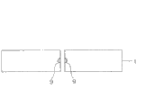
Figure 16 is the sectional view along the XVI-XVI line of processing object thing 1 shown in Figure 15 (C).As shown in figure 16, not remaining unmodified regional 101b on processing object thing 1.The example of the photo after the zone C 1 of taking among Figure 16 is illustrated among Figure 17.Figure 17 is the laser processing formation modification area 71~76 that expression relates to by utilizing present embodiment, the figure of the photo of an embodiment of the section of the processing object thing 1 that is cut off.The corresponding zone of unmodified regional 101b that in Figure 17, can't see and in the regional P1 of Figure 22, be identified.
In the laser processing that present embodiment relates to, shown in Figure 20 (A) and Figure 20 (B), compare with the method that after forming modification area 171, forms modification area 172, when the irradiating laser L, the height of modification area on the thickness direction of processing object thing 1 that can cover laser L be step-down.Therefore, unmodified regional 101b as shown in Figure 21 is difficult to produce, so can prevent the generation at fragment or skirt shape edge (skirt) and can cut off processing object thing 1 accurately.Therefore, the quality of cutting off of processing object thing 1 is improved.In addition, under the thickness d of processing object thing 1 was situation more than the 300 μ m, it is remarkable that the effect of the laser processing that present embodiment relates to becomes.Below, use Figure 18 to elaborate.
Figure 18 is to use laser processing that present embodiment relates to form the summary sectional view of the processing object thing 1 in the operation of modification area 71~76 o'clock.Figure 18 is the operation example that expression forms modification area 72.The modification area 72a that becomes the part of modification area 72 scans the inside that is formed on processing object thing 1 by the laser L that lens LL is assembled.At this moment, to compare with modification area 171 shown in Figure 24 be low to the height of the modification area 71 on the thickness direction of processing object thing 1.Therefore, in Figure 18, have unmodified regional 101b shown in Figure 24 hardly.
In addition, in the present embodiment, in first operation, be after forming modification area 71, to form modification area 72 again, and in second operation, be after forming modification area 73, to form modification area 74 again.And forming with this order under the situation of modification area 71~74, because at the formation modification area laser L is moved along cutting off preset lines 5b, so between first operation and second operation, there is no need to change the moving direction (with reference to Figure 14 (B) and Figure 14 (C)) of laser L.Thereby, can be in the short time and form modification area 73 accurately.
Similarly, in second operation, be after forming modification area 73, form modification area 74 again, and in the 3rd operation, be after forming modification area 75, to form modification area 76 again, so but short time and form modification area 75 (with reference to Figure 15 (A) and Figure 15 (B)) accurately.
In addition, preferred, when forming modification area 71, first plane of incidence information of record plane of incidence 1a, and use its first plane of incidence information to form modification area 74.First plane of incidence information for example is, can collect successively along cutting off preset lines 5a be present in plane of incidence 1a concavo-convex on the thickness direction of processing object thing 1 elevation information and obtain.When first plane of incidence information of use, modification area 74,75 is aimed at along the concavo-convex of the plane of incidence 1a that cuts off preset lines 5a or fluctuating, and can be to form with modification area 71 essentially identical shapes.
Similarly, preferred, when forming modification area 72, second plane of incidence information of record plane of incidence 1a, and use its second plane of incidence information to form modification area 73.Second plane of incidence information for example is, can collect successively along cutting off preset lines 5b be present in plane of incidence 1a concavo-convex on the thickness direction of processing object thing 1 elevation information and obtain.When using second plane of incidence information, be modification area 73,76 can be aimed at along the concavo-convex of the plane of incidence 1a that cuts off preset lines 5b or rise and fall and to form with modification area 72 essentially identical shapes.
Above-mentioned elevation information is for example measured as follows.That is, at first, shine with laser and to plane of incidence 1a with lens light gathering mensuration, and detect the reverberation of this mensuration with laser.And the reverberation according to being detected has the actuator of piezoelectric element to make lens displacement by use, is positioned on the plane of incidence 1a with laser focus point so that measure.And obtain this displacement as elevation information.
In addition, as shown in figure 19, for example modification area 71 can be that modification area 71a~71f by the multiple row that is set up in parallel on the thickness direction of processing object thing 1 is constituted.Figure 19 is the stereogram of an example of expression modification area 71.Similarly, the modification area (not shown) of modification area 72~76 multiple row that also can serve as reasons on the thickness direction of processing object thing 1 to be set up in parallel constitutes.In this case, the height of the modification area 71~76 of the thickness direction of processing object thing 1 all can uprise, and can control its height.In addition, can cover laser L for preventing established modification area, preferred, modification area 71a~71f is from forming in regular turn from plane of incidence 1a position far away.In addition, modification area 71a~71f is same with above-mentioned modification area 7, can be made of the continuous modification area that forms, also can be by being constituted every the modification area that intermittently forms with the interval of regulation.
In addition, at least 1 modification area by multiple row in promptly can modification area 71~76 is constituted, and modification area 71~76 that also can be whole is constituted by the modification area by multiple row.
In addition, modification area 71 and modification area 72 also can be made of the modification area of the same ordered series of numbers of the thickness direction that is configured in processing object thing 1.Thus, the height of the modification area 71 of the thickness direction of processing object thing 1 and modification area 72 becomes unanimity easily.For example shown in Figure 19, preferred under the situation that modification area 71 is constituted for the modification area 71a~71f by 6 row, modification area 72 is also constituted by the modification area (not shown) by 6 row.
Similarly, modification area 73 and modification area 74 also can be made of the modification area of the same ordered series of numbers of the thickness direction that is configured in processing object thing 1, and modification area 75 and modification area 76 also can be made of the modification area of the same ordered series of numbers of the thickness direction that is configured in processing object thing 1.In addition, also can be (a) modification area 71,72, (b) modification area 73,74, reach (c) modification area 75,76, and central at least 1 is made of the modification area with ordered series of numbers.For example, can exemplify out, modification area 71 and modification area 72 be made of the modification area with ordered series of numbers, but modification area 73 and modification area 74 are the modification areas by mutual different columns to be constituted, and modification area 75 and modification area 76 are all by the situation that modification area constituted of different columns.
Aspect other example, can enumerate modification area 71 and modification area 72 is that (columns modification area a) is constituted by same ordered series of numbers, modification area 73 and modification area 74 are that the modification area by same ordered series of numbers (columns b) is constituted, and modification area 75 and modification area 76 are the situations that modification area constituted by same ordered series of numbers (columns c).In this case, columns a, columns b and columns c promptly can be identical, also can inequality.
More than be the detailed description of doing at the present invention's preferred forms, yet the present invention is not limited to above-mentioned embodiment.
For example, in first operation, be not specially limited in order to the order that forms modification area 71,72.In addition, in second operation, the order that forms modification area 73,74 is not specially limited yet.And in the 3rd operation, the order that forms modification area 75,76 is not specially limited yet.In specific words, in first operation, also can after forming modification area 71, form modification area 72 again.In addition, in second operation, also can after forming modification area 74, form modification area 73 again.Moreover, in the 3rd operation, also can after forming modification area 76, form modification area 75 again.
In addition, also can be by first~the 3rd operation repeatedly and on the thickness direction of processing object thing 1, form modification area again.For example, after the 3rd operation, also can on the thickness direction of processing object thing 1, alternatively form again along the modification area that cuts off preset lines 5a with along the modification area that cuts off preset lines 5b.Thus, can be adjusted at the height of the modification area on the thickness direction of processing object thing 1 according to the thickness of processing object thing 1.
In addition, modification area 71~76 is not defined as by the inside at processing object thing 1 and produces the situation that the multi-photon absorption is formed.Modification area 71~76 also can be to absorb the situation that equal light absorption is formed by making processing object thing 1 inner the generation with multi-photon.
In addition, in the present embodiment, the semiconductor wafer that is to use silicon system is as processing object thing 1, but the material of semiconductor wafer is not subject to this.Aspect the material of semiconductor wafer, for example can exemplify out, the IV family elemental semiconductor beyond the silicon, comprise the IV family element of SiC and so on compound semiconductor, comprise III-V group element compound semiconductor, comprise the compound semiconductor of II-VI family element and be doped with semiconductor of various adulterants (impurity) or the like.
At this, elaborate in proper order at the cut-out of the processing object thing 1 among the above-mentioned embodiment shown in Figure 17, but the present invention is defined in this embodiment.In this embodiment, processing object thing 1 is the silicon wafer of thickness 725 μ m.In addition, for example modification area 71 is by the 6 modification area 71a~71f formed (with reference to Figure 19) that are listed as that are set up in parallel on the thickness direction of processing object thing 1.That is modification area 71 is (with reference to Figure 15 (A)) that form by the scanning operation of carrying out laser L is moved along cut-out preset lines 5a.Each scan operation be by making focus point P the position according to move closer to plane of incidence 1a towards and on 6 stages, move and carry out.
Similarly, modification area 72~74th, formed by the modification area of 6 row that on the thickness direction of processing object thing 1, are set up in parallel, modification area the 75, the 76th, formed by the modification area of 7 row that on the thickness direction of processing object thing 1, are set up in parallel.Therefore, modification area the 71,74, the 75th adds up to the modification area by 19 row to be constituted, and modification area 72,73,76 also is to add up to the modification area by 19 row to be constituted (with reference to Figure 16).
After forming such modification area 71~76, on processing object thing 1, attach expansion bands, utilize expanding unit processing object thing 1 to be cut off again together with this expansion bands.The photo of taking the section of the processing object thing 1 that so cuts off is illustrated among Figure 17, as figure.
Then, describe at the laser processing condition that forms in the above-described embodiments when the modification area 71~76.The pulsewidth of laser L is 180ns, and the irradiation position of laser L (pulse distance) at interval is 4 μ m, and the frequency number of laser L is 75kHz.In addition, the translational speed of the objective table of processing object thing 1 is arranged is 300mm/s to mounting.Moreover the distance (focus point position) of plane of incidence 1a till the focus point P is as shown in table 1 with the relation of the energy of laser L.
[table 1]

Industrial utilizability
If according to the present invention, then can provide a kind of workpiece that can cut off accurately Laser processing.
Claims (6)
1. a laser processing is characterized in that, comprising:
First operation, cut off preset lines by making focus point aim at the inside of tabular processing object thing and irradiating laser along first of described processing object thing, to be formed on the inside of described processing object thing as first modification area that cuts off starting point, and along with described first cut off the second cut-out preset lines that preset lines is intersected, in the mode of intersecting with at least a portion of described first modification area, will be formed on the inside of described processing object thing as second modification area that cuts off starting point; And
Second operation, after described first operation, aim at the inside and the irradiating laser of described processing object thing by making focus point, the inside of the described processing object thing between the plane of incidence of the described processing object thing of described first modification area and described laser incident, cutting off preset lines along described first forms as the 3rd modification area that cuts off starting point, and the inside of the described processing object thing between described second modification area and the described plane of incidence, cut off preset lines along described second, form the 4th modification area as the cut-out starting point in the mode of intersecting with at least a portion of described the 3rd modification area.
2. laser processing according to claim 1 is characterized in that:
In described first operation, after forming described first modification area, form described second modification area,
In described second operation, after forming described the 3rd modification area, form described the 4th modification area.
3. laser processing according to claim 1 is characterized in that:
In described first operation, after forming described first modification area, form described second modification area,
In described second operation, after forming described the 4th modification area, form described the 3rd modification area.
4. laser processing according to claim 1 is characterized in that:
When forming described first modification area, write down first plane of incidence information of the described plane of incidence, and use this first plane of incidence information to form described the 3rd modification area,
When forming described second modification area, write down second plane of incidence information of the described plane of incidence, and use this second plane of incidence information to form described the 4th modification area.
5. laser processing according to claim 1 is characterized in that:
At least 1 of described first~the 4th modification area is that the modification area by the multiple row that is set up in parallel on the thickness direction of described processing object thing constitutes.
6. laser processing according to claim 1 is characterized in that:
At least one side among one side at one side at described first and second modification area place or the described the 3rd and the 4th modification area place is that the modification area by the same ordered series of numbers on the thickness direction that is arranged on described processing object thing constitutes.
Applications Claiming Priority (2)
| Application Number | Priority Date | Filing Date | Title |
|---|---|---|---|
| JP2004224505A JP4634089B2 (en) | 2004-07-30 | 2004-07-30 | Laser processing method |
| JP224505/2004 | 2004-07-30 |
Publications (2)
| Publication Number | Publication Date |
|---|---|
| CN1993200A CN1993200A (en) | 2007-07-04 |
| CN100496859C true CN100496859C (en) | 2009-06-10 |
Family
ID=35786122
Family Applications (1)
| Application Number | Title | Priority Date | Filing Date |
|---|---|---|---|
| CNB2005800257931A Active CN100496859C (en) | 2004-07-30 | 2005-07-14 | Laser processing method |
Country Status (11)
| Country | Link |
|---|---|
| US (1) | US7709767B2 (en) |
| EP (1) | EP1777031B1 (en) |
| JP (1) | JP4634089B2 (en) |
| KR (1) | KR101216793B1 (en) |
| CN (1) | CN100496859C (en) |
| AT (1) | ATE469724T1 (en) |
| DE (1) | DE602005021642D1 (en) |
| ES (1) | ES2344708T3 (en) |
| MY (1) | MY141090A (en) |
| TW (1) | TWI354596B (en) |
| WO (1) | WO2006011372A1 (en) |
Families Citing this family (64)
| Publication number | Priority date | Publication date | Assignee | Title |
|---|---|---|---|---|
| JP4659300B2 (en) * | 2000-09-13 | 2011-03-30 | 浜松ホトニクス株式会社 | Laser processing method and semiconductor chip manufacturing method |
| TWI326626B (en) * | 2002-03-12 | 2010-07-01 | Hamamatsu Photonics Kk | Laser processing method |
| US7749867B2 (en) * | 2002-03-12 | 2010-07-06 | Hamamatsu Photonics K.K. | Method of cutting processed object |
| ES2377521T3 (en) | 2002-03-12 | 2012-03-28 | Hamamatsu Photonics K.K. | Method to divide a substrate |
| TWI520269B (en) | 2002-12-03 | 2016-02-01 | Hamamatsu Photonics Kk | Cutting method of semiconductor substrate |
| FR2852250B1 (en) * | 2003-03-11 | 2009-07-24 | Jean Luc Jouvin | PROTECTIVE SHEATH FOR CANNULA, AN INJECTION KIT COMPRISING SUCH ANKLE AND NEEDLE EQUIPPED WITH SUCH ANKLE |
| US8685838B2 (en) * | 2003-03-12 | 2014-04-01 | Hamamatsu Photonics K.K. | Laser beam machining method |
| US7605344B2 (en) * | 2003-07-18 | 2009-10-20 | Hamamatsu Photonics K.K. | Laser beam machining method, laser beam machining apparatus, and laser beam machining product |
| JP4563097B2 (en) | 2003-09-10 | 2010-10-13 | 浜松ホトニクス株式会社 | Semiconductor substrate cutting method |
| JP4601965B2 (en) * | 2004-01-09 | 2010-12-22 | 浜松ホトニクス株式会社 | Laser processing method and laser processing apparatus |
| JP4598407B2 (en) * | 2004-01-09 | 2010-12-15 | 浜松ホトニクス株式会社 | Laser processing method and laser processing apparatus |
| JP4509578B2 (en) | 2004-01-09 | 2010-07-21 | 浜松ホトニクス株式会社 | Laser processing method and laser processing apparatus |
| JP5138219B2 (en) | 2004-03-30 | 2013-02-06 | 浜松ホトニクス株式会社 | Laser processing method |
| JP4694795B2 (en) * | 2004-05-18 | 2011-06-08 | 株式会社ディスコ | Wafer division method |
| JP4634089B2 (en) | 2004-07-30 | 2011-02-16 | 浜松ホトニクス株式会社 | Laser processing method |
| CN100548564C (en) * | 2004-08-06 | 2009-10-14 | 浜松光子学株式会社 | Laser processing and semiconductor device |
| JP4762653B2 (en) * | 2005-09-16 | 2011-08-31 | 浜松ホトニクス株式会社 | Laser processing method and laser processing apparatus |
| JP4907965B2 (en) * | 2005-11-25 | 2012-04-04 | 浜松ホトニクス株式会社 | Laser processing method |
| JP4804911B2 (en) * | 2005-12-22 | 2011-11-02 | 浜松ホトニクス株式会社 | Laser processing equipment |
| JP4907984B2 (en) * | 2005-12-27 | 2012-04-04 | 浜松ホトニクス株式会社 | Laser processing method and semiconductor chip |
| JP4322881B2 (en) * | 2006-03-14 | 2009-09-02 | 浜松ホトニクス株式会社 | Laser processing method and laser processing apparatus |
| ES2428826T3 (en) | 2006-07-03 | 2013-11-11 | Hamamatsu Photonics K.K. | Laser and chip processing procedure |
| JP5183892B2 (en) | 2006-07-03 | 2013-04-17 | 浜松ホトニクス株式会社 | Laser processing method |
| JP2008028347A (en) * | 2006-07-25 | 2008-02-07 | Disco Abrasive Syst Ltd | Method of forming embrittled regions |
| US8188404B2 (en) * | 2006-09-19 | 2012-05-29 | Hamamatsu Photonics K.K. | Laser processing method and laser processing apparatus |
| JP4954653B2 (en) | 2006-09-19 | 2012-06-20 | 浜松ホトニクス株式会社 | Laser processing method |
| JP5101073B2 (en) * | 2006-10-02 | 2012-12-19 | 浜松ホトニクス株式会社 | Laser processing equipment |
| JP4964554B2 (en) * | 2006-10-03 | 2012-07-04 | 浜松ホトニクス株式会社 | Laser processing method |
| JP5132911B2 (en) * | 2006-10-03 | 2013-01-30 | 浜松ホトニクス株式会社 | Laser processing method |
| KR101428824B1 (en) * | 2006-10-04 | 2014-08-11 | 하마마츠 포토닉스 가부시키가이샤 | Laser processing method |
| JP5336054B2 (en) | 2007-07-18 | 2013-11-06 | 浜松ホトニクス株式会社 | Processing information supply system provided with processing information supply device |
| JP4402708B2 (en) | 2007-08-03 | 2010-01-20 | 浜松ホトニクス株式会社 | Laser processing method, laser processing apparatus and manufacturing method thereof |
| JP5449665B2 (en) * | 2007-10-30 | 2014-03-19 | 浜松ホトニクス株式会社 | Laser processing method |
| JP5134928B2 (en) * | 2007-11-30 | 2013-01-30 | 浜松ホトニクス株式会社 | Workpiece grinding method |
| JP5054496B2 (en) * | 2007-11-30 | 2012-10-24 | 浜松ホトニクス株式会社 | Processing object cutting method |
| JP5692969B2 (en) | 2008-09-01 | 2015-04-01 | 浜松ホトニクス株式会社 | Aberration correction method, laser processing method using this aberration correction method, laser irradiation method using this aberration correction method, aberration correction apparatus, and aberration correction program |
| JP5254761B2 (en) | 2008-11-28 | 2013-08-07 | 浜松ホトニクス株式会社 | Laser processing equipment |
| JP5241527B2 (en) | 2009-01-09 | 2013-07-17 | 浜松ホトニクス株式会社 | Laser processing equipment |
| JP5241525B2 (en) | 2009-01-09 | 2013-07-17 | 浜松ホトニクス株式会社 | Laser processing equipment |
| WO2010090111A1 (en) | 2009-02-09 | 2010-08-12 | 浜松ホトニクス株式会社 | Workpiece cutting method |
| US9035216B2 (en) | 2009-04-07 | 2015-05-19 | Hamamatsu Photonics K.K. | Method and device for controlling interior fractures by controlling the laser pulse width |
| JP5491761B2 (en) | 2009-04-20 | 2014-05-14 | 浜松ホトニクス株式会社 | Laser processing equipment |
| JP5379604B2 (en) | 2009-08-21 | 2013-12-25 | 浜松ホトニクス株式会社 | Laser processing method and chip |
| JP2011146973A (en) * | 2010-01-15 | 2011-07-28 | Seiko Epson Corp | Method of manufacturing piezoelectric device |
| KR101704028B1 (en) * | 2010-06-21 | 2017-02-07 | 엘지이노텍 주식회사 | Light emitting device |
| JP5597051B2 (en) * | 2010-07-21 | 2014-10-01 | 浜松ホトニクス株式会社 | Laser processing method |
| JP5653110B2 (en) | 2010-07-26 | 2015-01-14 | 浜松ホトニクス株式会社 | Chip manufacturing method |
| US8722516B2 (en) | 2010-09-28 | 2014-05-13 | Hamamatsu Photonics K.K. | Laser processing method and method for manufacturing light-emitting device |
| CN103890908B (en) | 2011-10-18 | 2016-08-24 | 富士电机株式会社 | The stripping means of the supporting substrates of solid phase bound wafer and the manufacture method of semiconductor device |
| JP6035127B2 (en) * | 2012-11-29 | 2016-11-30 | 三星ダイヤモンド工業株式会社 | Laser processing method and laser processing apparatus |
| WO2014163188A1 (en) | 2013-04-04 | 2014-10-09 | 富士電機株式会社 | Method for manufacturing semiconductor device |
| DE112013007305A5 (en) | 2013-08-07 | 2016-06-02 | Trumpf Laser- Und Systemtechnik Gmbh | Method for processing a plate-like workpiece with a transparent, glassy, vitreous, ceramic and / or crystalline layer, separating device for such a workpiece and product from such a workpiece |
| US11420894B2 (en) | 2015-04-24 | 2022-08-23 | Nanoplus Ltd. | Brittle object cutting apparatus and cutting method thereof |
| CN105365061A (en) * | 2015-11-18 | 2016-03-02 | 无锡科诺达电子有限公司 | Precise cutting instrument for sapphires |
| JP6636384B2 (en) * | 2016-05-13 | 2020-01-29 | 株式会社ディスコ | Wafer processing method |
| JP6745165B2 (en) * | 2016-08-09 | 2020-08-26 | 株式会社ディスコ | Wafer processing method |
| JP6746211B2 (en) * | 2016-09-21 | 2020-08-26 | 株式会社ディスコ | Wafer processing method |
| JP6775880B2 (en) * | 2016-09-21 | 2020-10-28 | 株式会社ディスコ | Wafer processing method |
| US10562130B1 (en) | 2018-12-29 | 2020-02-18 | Cree, Inc. | Laser-assisted method for parting crystalline material |
| US11024501B2 (en) | 2018-12-29 | 2021-06-01 | Cree, Inc. | Carrier-assisted method for parting crystalline material along laser damage region |
| US10576585B1 (en) | 2018-12-29 | 2020-03-03 | Cree, Inc. | Laser-assisted method for parting crystalline material |
| US10611052B1 (en) | 2019-05-17 | 2020-04-07 | Cree, Inc. | Silicon carbide wafers with relaxed positive bow and related methods |
| JP7286464B2 (en) * | 2019-08-02 | 2023-06-05 | 株式会社ディスコ | Laser processing equipment |
| CN110646875A (en) * | 2019-09-26 | 2020-01-03 | 东莞市微科光电科技有限公司 | Optical filter manufacturing method |
Family Cites Families (7)
| Publication number | Priority date | Publication date | Assignee | Title |
|---|---|---|---|---|
| JPH01225510A (en) * | 1988-03-04 | 1989-09-08 | Sumitomo Electric Ind Ltd | Cutting and dividing method for semiconductor base |
| JP4659300B2 (en) * | 2000-09-13 | 2011-03-30 | 浜松ホトニクス株式会社 | Laser processing method and semiconductor chip manufacturing method |
| JP3626442B2 (en) * | 2000-09-13 | 2005-03-09 | 浜松ホトニクス株式会社 | Laser processing method |
| JP3624909B2 (en) * | 2002-03-12 | 2005-03-02 | 浜松ホトニクス株式会社 | Laser processing method |
| JP4050534B2 (en) * | 2002-03-12 | 2008-02-20 | 浜松ホトニクス株式会社 | Laser processing method |
| JP4634089B2 (en) | 2004-07-30 | 2011-02-16 | 浜松ホトニクス株式会社 | Laser processing method |
| JP5162163B2 (en) * | 2007-06-27 | 2013-03-13 | 株式会社ディスコ | Wafer laser processing method |
-
2004
- 2004-07-30 JP JP2004224505A patent/JP4634089B2/en active Active
-
2005
- 2005-07-14 WO PCT/JP2005/013055 patent/WO2006011372A1/en active Application Filing
- 2005-07-14 US US11/658,703 patent/US7709767B2/en active Active
- 2005-07-14 DE DE602005021642T patent/DE602005021642D1/en active Active
- 2005-07-14 CN CNB2005800257931A patent/CN100496859C/en active Active
- 2005-07-14 KR KR1020077004750A patent/KR101216793B1/en active IP Right Grant
- 2005-07-14 AT AT05765811T patent/ATE469724T1/en not_active IP Right Cessation
- 2005-07-14 ES ES05765811T patent/ES2344708T3/en active Active
- 2005-07-14 EP EP05765811A patent/EP1777031B1/en active Active
- 2005-07-20 TW TW094124481A patent/TWI354596B/en active
- 2005-07-28 MY MYPI20053468A patent/MY141090A/en unknown
Also Published As
| Publication number | Publication date |
|---|---|
| EP1777031A1 (en) | 2007-04-25 |
| KR101216793B1 (en) | 2012-12-28 |
| TWI354596B (en) | 2011-12-21 |
| JP2006043713A (en) | 2006-02-16 |
| EP1777031A4 (en) | 2009-04-29 |
| ATE469724T1 (en) | 2010-06-15 |
| MY141090A (en) | 2010-03-15 |
| TW200610604A (en) | 2006-04-01 |
| JP4634089B2 (en) | 2011-02-16 |
| KR20070049186A (en) | 2007-05-10 |
| EP1777031B1 (en) | 2010-06-02 |
| DE602005021642D1 (en) | 2010-07-15 |
| US7709767B2 (en) | 2010-05-04 |
| ES2344708T3 (en) | 2010-09-03 |
| US20090026185A1 (en) | 2009-01-29 |
| CN1993200A (en) | 2007-07-04 |
| WO2006011372A1 (en) | 2006-02-02 |
Similar Documents
| Publication | Publication Date | Title |
|---|---|---|
| CN100496859C (en) | Laser processing method | |
| CN101461039B (en) | Laser material processing method | |
| CN101100018B (en) | Laser processing method and chip | |
| CN101218664B (en) | Method for cutting workpiece | |
| CN101522362B (en) | Laser processing method | |
| CN102172799B (en) | Laser processing method and laser processing device | |
| CN101516565B (en) | Laser processing method | |
| CN101516566B (en) | Laser processing method and laser processing apparatus | |
| CN101434010A (en) | Laser processing method and semiconductor device | |
| JP5269356B2 (en) | Laser processing method | |
| JP5117806B2 (en) | Laser processing method and laser processing apparatus | |
| JP5122161B2 (en) | Processing object cutting method |
Legal Events
| Date | Code | Title | Description |
|---|---|---|---|
| C06 | Publication | ||
| PB01 | Publication | ||
| C10 | Entry into substantive examination | ||
| SE01 | Entry into force of request for substantive examination | ||
| C14 | Grant of patent or utility model | ||
| GR01 | Patent grant |