CN100485373C - Short wave length X-ray diffraction measuring device and method - Google Patents
Short wave length X-ray diffraction measuring device and method Download PDFInfo
- Publication number
- CN100485373C CN100485373C CNB2004100688802A CN200410068880A CN100485373C CN 100485373 C CN100485373 C CN 100485373C CN B2004100688802 A CNB2004100688802 A CN B2004100688802A CN 200410068880 A CN200410068880 A CN 200410068880A CN 100485373 C CN100485373 C CN 100485373C
- Authority
- CN
- China
- Prior art keywords
- detector
- ray
- circle
- angular instrument
- diaphragm
- Prior art date
- Legal status (The legal status is an assumption and is not a legal conclusion. Google has not performed a legal analysis and makes no representation as to the accuracy of the status listed.)
- Expired - Lifetime
Links
Images


Classifications
-
- G—PHYSICS
- G01—MEASURING; TESTING
- G01N—INVESTIGATING OR ANALYSING MATERIALS BY DETERMINING THEIR CHEMICAL OR PHYSICAL PROPERTIES
- G01N23/00—Investigating or analysing materials by the use of wave or particle radiation, e.g. X-rays or neutrons, not covered by groups G01N3/00 – G01N17/00, G01N21/00 or G01N22/00
- G01N23/20—Investigating or analysing materials by the use of wave or particle radiation, e.g. X-rays or neutrons, not covered by groups G01N3/00 – G01N17/00, G01N21/00 or G01N22/00 by using diffraction of the radiation by the materials, e.g. for investigating crystal structure; by using scattering of the radiation by the materials, e.g. for investigating non-crystalline materials; by using reflection of the radiation by the materials
- G01N23/207—Diffractometry using detectors, e.g. using a probe in a central position and one or more displaceable detectors in circumferential positions
-
- G—PHYSICS
- G01—MEASURING; TESTING
- G01N—INVESTIGATING OR ANALYSING MATERIALS BY DETERMINING THEIR CHEMICAL OR PHYSICAL PROPERTIES
- G01N23/00—Investigating or analysing materials by the use of wave or particle radiation, e.g. X-rays or neutrons, not covered by groups G01N3/00 – G01N17/00, G01N21/00 or G01N22/00
- G01N23/20—Investigating or analysing materials by the use of wave or particle radiation, e.g. X-rays or neutrons, not covered by groups G01N3/00 – G01N17/00, G01N21/00 or G01N22/00 by using diffraction of the radiation by the materials, e.g. for investigating crystal structure; by using scattering of the radiation by the materials, e.g. for investigating non-crystalline materials; by using reflection of the radiation by the materials
Landscapes
- Chemical & Material Sciences (AREA)
- Crystallography & Structural Chemistry (AREA)
- Physics & Mathematics (AREA)
- Health & Medical Sciences (AREA)
- Life Sciences & Earth Sciences (AREA)
- Analytical Chemistry (AREA)
- Biochemistry (AREA)
- General Health & Medical Sciences (AREA)
- General Physics & Mathematics (AREA)
- Immunology (AREA)
- Pathology (AREA)
- Analysing Materials By The Use Of Radiation (AREA)
Abstract
本发明涉及一种用于较低原子序数的晶体材料试样或工件的短波长X射线衍射断层扫描测量装置和方法。其装置包括X射线管、入射光阑、工作台、限位接收狭缝、测角仪、探测器、能量分析器,其特征在于:所述X射线管与所述探测器位于所述工作台两侧。本发明采用短波长X射线衍射透射法,在不破坏原子序数较低的晶体材料工件的前提下,能测得厚度更厚的工件不同深度不同部位的X射线衍射谱及其分布。本发明所述具有操作简便,检测时间不长,测得的X射线衍射谱真实、可靠。
The invention relates to a short-wavelength X-ray diffraction tomography measuring device and method for crystal material samples or workpieces with lower atomic numbers. The device includes an X-ray tube, an incident aperture, a workbench, a limit receiving slit, a goniometer, a detector, and an energy analyzer, and is characterized in that the X-ray tube and the detector are located on the workbench sides. The invention adopts the short-wavelength X-ray diffraction transmission method, and can measure the X-ray diffraction spectrum and its distribution at different depths and different parts of the thicker workpiece without destroying the crystal material workpiece with a lower atomic number. The invention has the advantages of simple and convenient operation, short detection time, and the measured X-ray diffraction spectrum is real and reliable.
Description
技术领域 technical field
本发明涉及一种X射线衍射的测量,特别是一种用于较低原子序数的晶体材料试样或工件的短波长X射线衍射断层扫描测量装置和方法。The invention relates to a measurement of X-ray diffraction, in particular to a short-wavelength X-ray diffraction tomography measurement device and method for crystal material samples or workpieces with lower atomic numbers.
背景技术 Background technique
目前的X射线衍射分析,常用Cu、Cr、Fe、Mo材料作为阳极靶的X射线管,由于这种X射线管发出的标识X射线波长较长,在镁、铝、硅等材料中的穿透深度不大于10-4m,所以至今只能对这类材料试样或工件的表面进行X射线衍射分析。大家也明白,对工件进行X射线衍射分析可以测定晶体物质的结构(如物相分析),以及晶体物质的结构变化(如测定残余应力)等。In current X-ray diffraction analysis, Cu, Cr, Fe, and Mo materials are commonly used as X-ray tubes for anode targets. Since the X-rays emitted by this X-ray tube have a longer wavelength, they can penetrate in materials such as magnesium, aluminum, and silicon. The penetration depth is not more than 10 -4 m, so until now only the surface of this kind of material sample or workpiece can be analyzed by X-ray diffraction. Everyone also understands that X-ray diffraction analysis of workpieces can determine the structure of crystalline substances (such as phase analysis), and the structural changes of crystalline substances (such as determining residual stress).
CN1049496C公开了一种“X射线残余应力测定装置和方法”,其装置是在现有X射线残余应力测定装置的基础上改X射线管为短波长X射线管,且管电压高,所用接收狭缝为限位接收狭缝,其方法是在现有装置的测定方法中采用短波长标识X射线,使被测点位于测角仪圆圆心,且通过限位接收狭缝,只允许被测点的衍射线进入辐射探测器,而将来自工件其它部位的衍射线和散射线屏蔽,可测定X射线穿透深度范围内的被测工件内部任意一点的残余应力;平移工件,X射线应力分析仪就可测定工件的另一点的残余应力,解决了残余应力在铍合金等材料工件的三维分布。但是由于X射线应力分析仪是采用X射线衍射背反射法来收集衍射谱,当采用短波长X射线辐射时,没能充分利用短波长X射线强穿透能力,导致被测工件的可测深度较小。CN1049496C discloses a kind of "X-ray residual stress measuring device and method", its device is to change the X-ray tube into a short-wavelength X-ray tube on the basis of the existing X-ray residual stress measuring device, and the tube voltage is high, and the used receiving narrow The slit is a limit receiving slit, and the method is to use short-wavelength marking X-rays in the measurement method of the existing device, so that the measured point is located at the center of the goniometer circle, and through the limit receiving slit, only the measured point is allowed Diffraction rays from other parts of the workpiece enter the radiation detector, and the diffraction rays and scattering rays from other parts of the workpiece are shielded, and the residual stress at any point inside the workpiece within the X-ray penetration depth range can be measured; translation workpiece, X-ray stress analyzer The residual stress at another point of the workpiece can be measured, and the three-dimensional distribution of the residual stress in the workpiece made of materials such as beryllium alloy can be solved. However, since the X-ray stress analyzer uses the X-ray diffraction back reflection method to collect the diffraction spectrum, when short-wavelength X-ray radiation is used, the strong penetrating ability of short-wavelength X-rays cannot be fully utilized, resulting in the measurable depth of the workpiece being measured. smaller.
发明内容 Contents of the invention
本发明的目的在于提供一种主要用于铝、镁、硅等较低原子序数的晶体材料试样或工件,使得工件的可测深度或厚度提高10倍左右的短波长X射线衍射分析的断层扫描装置。The purpose of the present invention is to provide a short-wavelength X-ray diffraction analysis tomography that is mainly used for crystal material samples or workpieces with lower atomic numbers such as aluminum, magnesium, silicon, etc., so that the measurable depth or thickness of the workpiece is increased by about 10 times scanning device.
本发明的另一目的在于提供一种操作简便、检测时间短的采用上述装置的短波长X射线衍射测量方法。Another object of the present invention is to provide a short-wavelength X-ray diffraction measurement method using the above-mentioned device, which is simple in operation and short in detection time.
众所周知,X射线波长越短,被辐射工件所用的材料原子序数越小,入射X射线的穿透工件的厚度就越大,本发明正是基于这一原理,采用X射线衍射透射法,而不是X射线衍射背反射法,将使得入射X射线与衍射线在工件中走过的路程之和大大减小,因此可收集来自厚度更厚的工件不同深度不同部位的X射线衍射线,以实现对整个工件内部进行无损地X射线衍射分析,从而测得物相、应力等的三维分布。As we all know, the shorter the wavelength of X-rays, the smaller the atomic number of the material used in the irradiated workpiece, and the greater the thickness of the incident X-rays penetrating the workpiece. The present invention is based on this principle and adopts the X-ray diffraction transmission method instead of The X-ray diffraction back-reflection method will greatly reduce the sum of the distance traveled by the incident X-ray and the diffraction line in the workpiece, so it can collect X-ray diffraction lines from different depths and different parts of the thicker workpiece to achieve Non-destructive X-ray diffraction analysis is performed inside the entire workpiece to measure the three-dimensional distribution of phase and stress.
本发明的目的是这样实现的:一种短波长X射线衍射测量装置,包括X射线管、入射光阑、工作台、接收狭缝、测角仪、探测器、能量分析器,其特征在于:所述X射线管与所述探测器位于所述工作台两侧。The object of the present invention is achieved like this: a kind of short-wavelength X-ray diffraction measurement device, comprises X-ray tube, incident aperture, workbench, receiving slit, goniometer, detector, energy analyzer, is characterized in that: The X-ray tube and the detector are located on both sides of the workbench.
上述接收狭缝、探测器固定在测角仪上,同步绕以工作台上被测工件被测点为圆心转动,此被测点位于测角仪的转轴上;测角仪固定在一个平台上;工作台或固定在测角仪上,或固定在平台上;X射线管或固定于测角仪上,或固定于平台上;入射光阑或固定于测角仪上,或固定于平台上,或固定于X射线管上的夹具;入射光阑出口或在测角仪圆周上,或在测角仪圆周内;工作台上的工件或随工作台分别作X、Y、Z三维方向平移或绕测角仪转轴转动Ψ角度或作X、Y、Z、Ψ联动。另外,本发明中的接收狭缝还起着只允许工件被测点的衍射线进入探测器而将散射线和来自工件其它部位的衍射线屏蔽的作用。The above-mentioned receiving slit and detector are fixed on the goniometer, and rotate synchronously around the measured point of the workpiece on the workbench as the center of the circle. The measured point is located on the rotating shaft of the goniometer; the goniometer is fixed on a platform The working table is either fixed on the goniometer or on the platform; the X-ray tube is either fixed on the goniometer or on the platform; the entrance aperture is either fixed on the goniometer or on the platform , or a fixture fixed on the X-ray tube; the exit of the incident aperture is either on the circumference of the goniometer, or within the circumference of the goniometer; the workpiece on the worktable or the three-dimensional translation in X, Y and Z directions with the worktable respectively Or rotate the Ψ angle around the goniometer shaft or do X, Y, Z, Ψ linkage. In addition, the receiving slit in the present invention also plays a role in allowing only the diffraction lines from the measured point of the workpiece to enter the detector while shielding the scattered rays and diffraction lines from other parts of the workpiece.
上述X射线管的阳极靶的材质为钨、金、银等重金属材料,使其发出穿透能力强的波长为0.01nm-0.07nm的短波长标识X射线,对原子序数比较低的(Z<20)金属、非金属材料和陶瓷材料等(如铝、镁、硅等),可以穿透厘米一分米数量级的深度;管电压为120-350KV,管电流为2-10mA,连续可调;上述探测器或为辐射探测器或为位敏探测器或为一维半导体探测器阵列;上述入射光阑为入射准直光阑;上述接收狭缝或为平行限位接收狭缝,或为锥度限位接收狭缝,以屏蔽入射到探测器的散射X射线和来自工件其他部位的衍射线;上述能量分析器或为单道能量分析器,或为多道能量分析器,其输出信号输入计算机;上述工作台由计算机控制,作X、Y、Z三维方向平行移动或绕测角仪转轴转动。The anode target of the above-mentioned X-ray tube is made of heavy metal materials such as tungsten, gold, silver, etc., so that it emits short-wavelength identification X-rays with a strong penetrating wavelength of 0.01nm-0.07nm, and is suitable for those with a relatively low atomic number (Z< 20) Metals, non-metallic materials and ceramic materials (such as aluminum, magnesium, silicon, etc.), can penetrate the depth of centimeters and decimeters; the tube voltage is 120-350KV, and the tube current is 2-10mA, which is continuously adjustable; The above-mentioned detectors are either radiation detectors or position-sensitive detectors or one-dimensional semiconductor detector arrays; the above-mentioned incident apertures are incident collimation apertures; the above-mentioned receiving slits are either parallel limit receiving slits or tapered The receiving slit is limited to shield the scattered X-rays incident on the detector and the diffraction lines from other parts of the workpiece; the above-mentioned energy analyzer is either a single-channel energy analyzer or a multi-channel energy analyzer, and its output signal is input to the computer ; The above-mentioned workbench is controlled by a computer, and moves in parallel in the three-dimensional directions of X, Y, and Z or rotates around the axis of the goniometer.
上述X射线管到测角仪圆的圆心距离与探测器到测角仪圆的圆心距离相等或不等,且距离可调;测角仪圆的圆心到辐射探测器或位敏探测器的距离为200-800mm。本发明所述的测角仪圆的圆心是测角仪的转轴与辐射探测器或位敏探测器的转动平面的交点,入射的X射线在辐射探测器或位敏探测器的转动平面上且经过测角仪圆的圆心,位于测角仪圆的圆心的被测工件部位就是被测部位。The distance from the above-mentioned X-ray tube to the center of the goniometer circle is equal or different from the distance from the detector to the center of the goniometer circle, and the distance is adjustable; the distance from the center of the goniometer circle to the radiation detector or position-sensitive detector 200-800mm. The center of the goniometer circle of the present invention is the intersection point of the rotating shaft of the goniometer and the rotation plane of the radiation detector or the position-sensitive detector, and the incident X-ray is on the rotation plane of the radiation detector or the position-sensitive detector and After passing through the center of the goniometer circle, the part of the workpiece to be measured located at the center of the goniometer circle is the measured part.
上述入射准直光阑或为圆孔入射准直光阑,或为矩形孔入射准直光阑;入射准直光阑的遮挡材料为铅或者比铅吸收X射线能力更强的重金属,比如金等。当采用闪烁计数器等单点辐射探测器扫描收集衍射谱时,平行限位接收狭缝采用圆孔入射准直光阑或矩形孔入射准直光阑,且平行限位接收狭缝与辐射探测器联动。The above-mentioned incident collimation diaphragm is either a circular hole entrance collimation diaphragm, or a rectangular hole entrance collimation diaphragm; the shielding material of the incident collimation diaphragm is lead or a heavy metal with stronger X-ray absorption ability than lead, such as gold wait. When single-point radiation detectors such as scintillation counters are used to scan and collect diffraction spectra, the parallel limit receiving slit adopts a circular hole incident collimation diaphragm or a rectangular hole incident collimation diaphragm, and the parallel limit receiving slit and the radiation detector linkage.
上述圆孔入射准直光阑的内径尺寸为0.1-2mm,长度为50-200mm;上述矩形孔入射准直光阑由2个或2个以上光阑构成,每个光阑互相同向平行且中心线重合,每个光阑遮挡材料厚度≥4mm,且间距20-200mm,每个光阑内孔尺寸为(1-4)×(0.1-0.8)mm,整个矩形孔入射准直光阑的遮挡材料总厚度不小于15mm。The inner diameter of the incident collimation diaphragm of the circular hole is 0.1-2 mm, and the length is 50-200 mm; the incident collimation diaphragm of the rectangular hole is composed of 2 or more diaphragms, and each diaphragm is parallel to each other and The center line coincides, the thickness of each diaphragm blocking material is ≥4mm, and the distance is 20-200mm, the inner hole size of each diaphragm is (1-4)×(0.1-0.8)mm, and the entire rectangular hole is incident on the collimating diaphragm The total thickness of the shielding material shall not be less than 15mm.
上述辐射探测器或位敏探测器用大于2mm厚的铅皮或者比铅吸收X射线能力更强的重金属皮封闭来屏蔽X射线,只留正对接收狭缝的窗口和引出电线的小孔。The above-mentioned radiation detector or position-sensitive detector is sealed with a lead skin more than 2mm thick or a heavy metal skin with a stronger X-ray absorption ability than lead to shield X-rays, leaving only the window facing the receiving slit and the small hole for the lead-out wire.
上述锥度限位接收狭缝的锥度由位敏探测器可探测的有限角度决定,外壳由厚度大于2mm的铅皮包覆,内镶3-10片钨或钼片且均分锥度限位接收狭缝的锥度;该狭缝的大口尺寸与位敏探测器的有效尺寸吻合且与位敏探测器固定连接,锥度限位接收狭缝的锥面和内镶的钨或钼片的延伸均相交于测角仪的转轴;锥度限位接收狭缝和位敏探测器联动。当采用位敏探测器收集衍射谱时,接收狭缝采用锥度限位接收狭缝。The taper of the above-mentioned taper limit receiving slit is determined by the limited angle that can be detected by the position sensitive detector. The shell is covered by lead skin with a thickness greater than 2mm, and 3-10 pieces of tungsten or molybdenum are embedded inside and the taper limit receiving slit is equally divided. The taper of the slit; the size of the large opening of the slit coincides with the effective size of the position-sensitive detector and is fixedly connected with the position-sensitive detector. The rotating shaft of the goniometer; the taper limit receiving slit is linked with the position sensitive detector. When the position-sensitive detector is used to collect the diffraction spectrum, the receiving slit adopts a tapered limit receiving slit.
本发明的另一目的是这样实现的:一种实施上述装置的短波长X射线衍射测量方法,其特征在于:它采用的是短波长X射线衍射透射法,(1)选择辐射和衍射测试参数,包括管电压、管电流、光阑和狭缝系统以及测角仪圆的圆心到辐射探测器或位敏探测器的距离等;(2)由计算机控制将工件被测点置于测角仪圆的圆心;(3)计算机控制测量衍射谱;(4)根据需要,由计算机控制工作台作X、Y、Z三维方向移动或绕测角仪转轴转动,便可测得工件内任意一点及其任一Ψ角的衍射谱;(5)由计算机进行数据处理,求得各点物相、残余应力参量及其分布。Another object of the present invention is achieved in this way: a short-wavelength X-ray diffraction measurement method implementing the above-mentioned device is characterized in that: what it adopted is a short-wavelength X-ray diffraction transmission method, (1) select radiation and diffraction test parameters , including tube voltage, tube current, aperture and slit system, and the distance from the center of the goniometer circle to the radiation detector or position-sensitive detector; (2) The measured point of the workpiece is placed on the goniometer by computer control The center of the circle; (3) The computer controls the measurement of the diffraction spectrum; (4) According to the needs, the computer controls the workbench to move in the X, Y, Z three-dimensional directions or rotate around the goniometer shaft to measure any point in the workpiece and Diffraction spectrum at any Ψ angle; (5) Data processing by computer to obtain the phase, residual stress parameters and distribution of each point.
选择辐射和衍射测试参数:采用W Kα、Au Kα、Ag Kα短波长X射线辐射;采用X射线衍射透射法;采用平行限位接收狭缝或锥度限位接收狭缝,只允许被测点的衍射线进入探测器,而将其余射线遮挡。Select radiation and diffraction test parameters: use W Kα, Au Kα, Ag Kα short-wavelength X-ray radiation; use X-ray diffraction transmission method; use parallel limit receiving slit or tapered limit receiving slit, only allow the measured point The diffracted rays enter the detector, while the remaining rays are blocked.
由计算机控制将工件被测点置于测角仪圆的圆心;所述工件被测点为工件表面或工件内部的任一部位。The measured point of the workpiece is placed at the center of the goniometer circle controlled by the computer; the measured point of the workpiece is any part on the surface of the workpiece or inside the workpiece.
测衍射谱时,可根据需要,由计算机控制被测工件位移转动台作X、Y、Z三维方向移动,其步长为0.1-2mm和绕测角仪转轴转动,以测得工件内任意一点及其任一绕测角低度转轴转动角度的衍射谱。When measuring the diffraction spectrum, the computer can control the displacement of the workpiece to move in the three-dimensional directions of X, Y, and Z according to the needs, and the step length is 0.1-2mm and rotate around the axis of the goniometer to measure any point in the workpiece. The diffraction spectrum of any rotation angle around the low-degree rotation axis of the measurement angle.
本发明所述装置在不破坏原子序数较低的铝、镁、硅、碳、氮、氧等元素构成的晶体材料工件的前提下,能测得厚度更厚的工件不同深度不同部位的X射线衍射谱。本发明克服了短波长X射线不适用于X射线衍射分析领域的惯性思维束缚,采用短波长X射线辐射+X射线衍射透射法,使得可测工件厚度约为现有技术CN1049496C所述装置和方法可测工件厚度的10倍左右,特别是对硅、铝、镁等材料工件的可测厚度达到厘米一分米数量级,能测得工件不同深度不同部位的X射线衍射谱,进而可获得物相、残余应力等参量及其分布;而且,本发明也突破了现有的X射线衍射仪及其方法在不破坏试样的情况下,只能对试样表面几十微米厚进行X射线衍射分析的局限;并且,具有操作简便,检测时间不长,测得的X射线衍射谱真实、可靠。The device of the present invention can measure X-rays at different depths and different parts of thicker workpieces without destroying crystal material workpieces composed of elements such as aluminum, magnesium, silicon, carbon, nitrogen, and oxygen with lower atomic numbers. Diffraction spectrum. The present invention overcomes the constraints of inertial thinking that short-wavelength X-rays are not suitable for the field of X-ray diffraction analysis, and adopts short-wavelength X-ray radiation + X-ray diffraction transmission method, so that the thickness of the measurable workpiece is about the device and method described in the prior art CN1049496C The measurable thickness of the workpiece is about 10 times, especially for silicon, aluminum, magnesium and other material workpieces. , residual stress and other parameters and their distribution; moreover, the present invention also breaks through the existing X-ray diffractometer and its method, and can only perform X-ray diffraction analysis on the surface of the sample tens of microns thick without destroying the sample. limitations; moreover, it is easy to operate, the detection time is not long, and the measured X-ray diffraction spectrum is true and reliable.
附图说明 Description of drawings
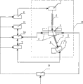
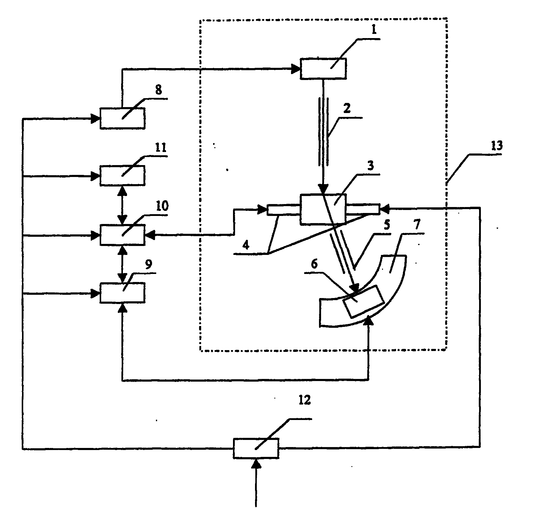
图1为本发明所述装置框图;Fig. 1 is a device block diagram of the present invention;
图2为本发明所采用的圆孔入射准直光阑结构剖面图;Fig. 2 is the cross-sectional view of the structure of the circular hole incident collimation diaphragm adopted by the present invention;
图3为图2的A向视图;Fig. 3 is the A direction view of Fig. 2;
图4为本发明所采用的矩形孔入射准直光阑结构剖面图;Fig. 4 is the cross-sectional view of the structure of the rectangular hole incident collimation diaphragm adopted by the present invention;
图5为图4的A向视图;Fig. 5 is the A direction view of Fig. 4;
图6为本发明所采用的锥度限位接收狭缝的结构剖面图,其中上端14为大口,下端15为小口;Fig. 6 is the structural sectional view of the taper limit receiving slit adopted by the present invention, wherein the
图7为图6的俯视图;Figure 7 is a top view of Figure 6;
图8为本发明的具体实施例中工件移动测量示意图;Fig. 8 is a schematic diagram of workpiece movement measurement in a specific embodiment of the present invention;
图9为本发明所采用的测量和计算框图;Fig. 9 is a measurement and calculation block diagram adopted by the present invention;
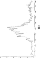
图10为25mm厚镁合金工件内部中心部位的衍射谱。Fig. 10 is the diffraction spectrum of the central part inside the 25mm thick magnesium alloy workpiece.
图中1为X射线管、2为入射准直光阑、3为工件、4为工作台、5为接收狭缝、6为探测器、7为测角仪、8为X射线发生器电源、9为能量分析器、10为计算机、11为数据输出设备、12为稳压电源、13为测量装置的固定平台、14为锥度限位接收狭缝的上端大口、15为锥度限位接收狭缝的下端小口。In the figure, 1 is the X-ray tube, 2 is the incident collimation aperture, 3 is the workpiece, 4 is the workbench, 5 is the receiving slit, 6 is the detector, 7 is the goniometer, 8 is the X-ray generator power supply, 9 is an energy analyzer, 10 is a computer, 11 is a data output device, 12 is a regulated power supply, 13 is a fixed platform of a measuring device, 14 is the upper end of the taper limit receiving slit, and 15 is a taper limit receiving slit The lower end of the small mouth.
具体实施方式 Detailed ways
实施例1:参见上述附图:一种短波长X射线衍射测量装置,包括X射线管1、入射光阑2、工作台4、接收狭缝5、测角仪7、探测器6、能量分析器9,其特征在于:所述X射线管1与所述探测器6位于所述工作台4两侧,也即被测工件两侧。Embodiment 1: Refer to the above accompanying drawings: a short-wavelength X-ray diffraction measurement device, including an
上述接收狭缝5、探测器6固定在测角仪7上,同步绕以工作台4上被测工件3被测点为圆心转动,此被测点位于测角仪7的转轴上;测角仪7固定在一个平台13上;工作台4固定在测角仪7上,或固定于平台13上;X射线管1或固定于测角仪7上,或固定于平台13上;入射光阑2或固定于测角仪7上,或固定于平台13上,或固定于X射线管1上的夹具;入射光阑2出口或在测角仪7的圆周上,或在测角仪7圆周内;工作台4上的被测工件3或随平台13分别作X、Y、Z三维方向平移或绕测角仪7转轴转动Ψ角度或作X、Y、Z、Ψ联动。The above-mentioned receiving
在本发明中,上述X射线管1的阳极靶的材质为钨、金、银等重金属材料,管电压为320KV,管电流为5mA,连续可调,使其发出穿透能力强的波长为0.01nm-0.07nm的短波长标识X射线,对原子序数比较低的(Z<20)金属、非金属材料和陶瓷材料等,如铝、镁、硅等,可以穿透厘米一分米数量级的深度;上述探测器6为位敏探测器;上述入射光阑2为入射准直光阑;上述接收狭缝5为锥度限位接收狭缝,屏蔽入射到探测器6的散射X射线和来自工件其他部位的衍射线,也即只允许被测点的衍射线进入探测器,而将其余射线遮挡;上述能量分析器9为多道能量分析器;上述工作台4由计算机10控制,作X、Y、Z三维方向移动、绕测角仪7转轴转动,多道能量分析器9的信号输入到计算机10。In the present invention, the material of the anode target of the above-mentioned
上述X射线管1到测角仪7圆的圆心距离与探测器6到测角仪7圆的圆心距离相等或不等,且距离可调;测角仪圆的圆心到辐射探测器或位敏探测器的距离为600mm。The distance between the above-mentioned
上述入射准直光阑或为圆孔入射准直光阑,或为矩形孔入射准直光阑;入射准直光阑的遮挡材料为铅或者比铅吸收X射线能力更强的重金属;当采用闪烁计数器等单点辐射探测器扫描收集衍射谱时,平行限位接收狭缝采用圆孔入射准直光阑或矩形孔入射准直光阑。The above-mentioned incident collimation diaphragm is either a circular hole entrance collimation diaphragm, or a rectangular hole entrance collimation diaphragm; the shielding material of the incident collimation diaphragm is lead or a heavy metal with stronger X-ray absorption ability than lead; when using When single-point radiation detectors such as scintillation counters scan to collect diffraction spectra, the parallel limit receiving slit adopts a circular hole incident collimation diaphragm or a rectangular hole incident collimation diaphragm.
上述圆孔入射准直光阑的内径尺寸为0.1-2mm,长度为50-200mm;上述矩形孔入射准直光阑由2个或2个以上光阑构成,每个光阑互相同向平行且中心线重合,每个光阑遮挡材料厚度5mm,且间距180mm,每个光阑内孔尺寸为(1-4)×(0.1-0.8)mm,整个矩形孔入射准直光阑的遮挡材料总厚度不小于15mm。The inner diameter of the incident collimation diaphragm of the circular hole is 0.1-2 mm, and the length is 50-200 mm; the incident collimation diaphragm of the rectangular hole is composed of 2 or more diaphragms, and each diaphragm is parallel to each other and The center line coincides, the thickness of each aperture blocking material is 5mm, and the distance is 180mm, the size of the inner hole of each aperture is (1-4)×(0.1-0.8) mm, the total blocking material of the entire rectangular hole incident on the collimating aperture The thickness is not less than 15mm.
上述辐射探测器或位敏探测器用大于2mm厚的铅皮或者比铅吸收X射线能力更强的重金属皮封闭来屏蔽X射线,只留正对接收狭缝5的窗口和引出电线的小孔。The above-mentioned radiation detector or position-sensitive detector is sealed with a lead skin more than 2 mm thick or a heavy metal skin with stronger X-ray absorption ability than lead to shield X-rays, leaving only the window facing the
上述锥度限位接收狭缝的锥度由位敏探测器可探测的有限角度决定,外壳由厚度大于2mm的铅皮包覆,内镶3-10片钨或钼片且均分锥度限位接收狭缝的锥度;该狭缝的大口14尺寸与位敏探测器的有效尺寸吻合且与位敏探测器固定连接,锥度限位接收狭缝的锥面和内镶的钨或钼片的延伸均相交于测角仪的转轴,其中心线相交于测角仪圆的圆心;锥度限位接收狭缝和位敏探测器联动。当采用位敏探测器收集衍射谱时,接收狭缝采用锥度限位接收狭缝。The taper of the above-mentioned taper limit receiving slit is determined by the limited angle that can be detected by the position sensitive detector. The shell is covered by lead skin with a thickness greater than 2mm, and 3-10 pieces of tungsten or molybdenum are embedded inside and the taper limit receiving slit is equally divided. The taper of the slit; the size of the
一种实施上述装置的短波长X射线衍射测量方法,其特征在于:它采用短波长X射线衍射透射法,(1)选择辐射和衍射测试参数,包括管电压、管电流、光阑和狭缝系统以及测角仪圆的圆心到辐射探测器或位敏探测器的距离等;(2)由计算机控制将工件被测点置于测角仪圆的圆心;(3)计算机控制测量衍射谱;(4)根据需要,由计算机控制工作台作X、Y、Z三维方向移动或绕测角仪转轴转动,便可测得工件内任意一点及其任一Ψ角的衍射谱;(5)由计算机进行数据处理,求得各点物相、残余应力参量及其分布。A short-wavelength X-ray diffraction measurement method implementing the above-mentioned device is characterized in that: it adopts a short-wavelength X-ray diffraction transmission method, (1) select radiation and diffraction test parameters, including tube voltage, tube current, aperture and slit system and the distance from the center of the goniometer circle to the radiation detector or position-sensitive detector; (2) the measured point of the workpiece is placed at the center of the goniometer circle by computer control; (3) the computer controls the measurement of the diffraction spectrum; (4) According to the needs, the computer controls the workbench to move in the three-dimensional directions of X, Y, and Z or rotate around the axis of the goniometer to measure the diffraction spectrum of any point in the workpiece and any Ψ angle; (5) by The computer performs data processing to obtain the phase, residual stress parameters and distribution of each point.
选择辐射和衍射测试参数:采用W Kα、Au Kα、Ag Kα短波长X射线辐射;采用X射线衍射透射法;采用平行限位接收狭缝或锥度限位接收狭缝,只允许被测点的衍射线进入探测器,而将其余射线遮挡。Select radiation and diffraction test parameters: use W Kα, Au Kα, Ag Kα short-wavelength X-ray radiation; use X-ray diffraction transmission method; use parallel limit receiving slit or tapered limit receiving slit, only allow the measured point The diffracted rays enter the detector, while the remaining rays are blocked.
由计算机控制工作台将其上的工件被测点置于测角仪圆的圆心,所述工件被测点为工件表面或工件内部的任一部位。为了实现断层逐点扫描,由计算机控制图8中工作台4上的被测工件3作空间三维运动,其步长为0.1-2mm,为了测量被测部位不同方向的衍射谱,也可以由计算机控制图8中的工作台4上的被测工件3绕测角仪转轴转动一定的角度。计算机对测得的数据进行处理,由输出设备输出被测工件内部各点的物相、残余应力等参量及其分布。The computer controls the workbench to place the measured point of the workpiece on the center of the goniometer circle, and the measured point of the workpiece is any part on the surface of the workpiece or inside the workpiece. In order to realize point-by-point scanning of the tomography, the measured
实施例2:参见图8,本例所采用的装置和方法同实施例1,所不同的是各参数的选择:本例采用W Kα辐射,管电压为280KV,管电流为3mA,测角仪圆的圆心到辐射探测器的距离为220mm±1.0,NaI闪烁计数器6接多道能量分析器9,入射准直光阑采用内径为2mm±0.1、长120mn±0.5的圆孔入射准直光阑,限位接收狭缝采用内径为0.5mm±0.1、长120mm±0.5的圆孔入射准直光阑,NaI闪烁计数器6用8mm±0.1厚的铅皮屏蔽。光路调好后,将厚度为25mm±0.5的镁合金铸件3置于工作台4上,调整工作台4使得镁合金铸件3的中心位于测角仪圆的圆心,图8中虚线所示为镁合金铸件3的实际位置,此时测角仪圆的圆心在镁合金铸件3的内部且距其表面12.5mm±0.1。2θ的扫描范围为2-10°,步长0.05°,每步的测量时间为10s。测得的X射线衍射谱见图10。Embodiment 2: Referring to Fig. 8, the device and method adopted in this example are the same as in Example 1, the difference is the selection of each parameter: this example adopts W Kα radiation, the tube voltage is 280KV, the tube current is 3mA, and the goniometer The distance from the center of the circle to the radiation detector is 220mm±1.0, the
实施例3:本例所采用的装置和方法同实施例1,所不同的是各参数的选择:本例采用W Kα辐射,管电压为320KV,管电流为6mA,测角仪圆的圆心到辐射探测器的距离为500mm±1.0,NaI闪烁计数器6接多道能量分析器9,入射准直光阑采用内径为1mrn±0.1、长150mm±0.5的圆孔入射准直光阑,限位接收狭缝采用内径为0.8mm±0.1、长120mm±0.5的圆孔入射准直光阑,NaI闪烁计数器6用10mm±0.1厚的铅皮屏蔽。光路调好后,将工件3置于工作台4上,调整工作台4使得工件3的中心位于测角仪圆的圆心,此时测角仪圆的圆心在工件3的内部。2θ的扫描范围为2-10°,步长0.05°,每步的测量时间为10s。Embodiment 3: The device and method adopted in this example are the same as in
Claims (9)
Priority Applications (6)
| Application Number | Priority Date | Filing Date | Title |
|---|---|---|---|
| CNB2004100688802A CN100485373C (en) | 2004-07-14 | 2004-07-14 | Short wave length X-ray diffraction measuring device and method |
| EP12183863.5A EP2541238B1 (en) | 2004-07-14 | 2005-06-30 | A measuring device for the short-wavelength X-ray diffraction and a method thereof |
| JP2007520648A JP2008506127A (en) | 2004-07-14 | 2005-06-30 | Short wavelength X-ray diffraction measurement apparatus and method |
| PCT/CN2005/000950 WO2006005246A1 (en) | 2004-07-14 | 2005-06-30 | A measuring device for the shortwavelength x ray diffraction and a method thereof |
| US11/572,128 US7583788B2 (en) | 2004-07-14 | 2005-06-30 | Measuring device for the shortwavelength x ray diffraction and a method thereof |
| EP05759557A EP1767928A4 (en) | 2004-07-14 | 2005-06-30 | A measuring device for the shortwavelength x ray diffraction and a method thereof |
Applications Claiming Priority (1)
| Application Number | Priority Date | Filing Date | Title |
|---|---|---|---|
| CNB2004100688802A CN100485373C (en) | 2004-07-14 | 2004-07-14 | Short wave length X-ray diffraction measuring device and method |
Publications (2)
| Publication Number | Publication Date |
|---|---|
| CN1588019A CN1588019A (en) | 2005-03-02 |
| CN100485373C true CN100485373C (en) | 2009-05-06 |
Family
ID=34604191
Family Applications (1)
| Application Number | Title | Priority Date | Filing Date |
|---|---|---|---|
| CNB2004100688802A Expired - Lifetime CN100485373C (en) | 2004-07-14 | 2004-07-14 | Short wave length X-ray diffraction measuring device and method |
Country Status (5)
| Country | Link |
|---|---|
| US (1) | US7583788B2 (en) |
| EP (2) | EP1767928A4 (en) |
| JP (1) | JP2008506127A (en) |
| CN (1) | CN100485373C (en) |
| WO (1) | WO2006005246A1 (en) |
Families Citing this family (32)
| Publication number | Priority date | Publication date | Assignee | Title |
|---|---|---|---|---|
| US7840237B2 (en) | 2007-02-08 | 2010-11-23 | Microsoft Corporation | Enabling user interface elements based on short range wireless devices |
| JP2009025234A (en) * | 2007-07-23 | 2009-02-05 | Rigaku Corp | Hard tissue evaluation method |
| US7978820B2 (en) * | 2009-10-22 | 2011-07-12 | Panalytical B.V. | X-ray diffraction and fluorescence |
| US8477904B2 (en) * | 2010-02-16 | 2013-07-02 | Panalytical B.V. | X-ray diffraction and computed tomography |
| CN102435626A (en) * | 2011-09-13 | 2012-05-02 | 丹东通达科技有限公司 | Table type X-ray diffractometer |
| CN102706905A (en) * | 2012-06-28 | 2012-10-03 | 丹东奥龙射线仪器有限公司 | Data recorder of X-ray crystal orientation device |
| CN103245445A (en) * | 2013-05-17 | 2013-08-14 | 北京师范大学 | Stress meter |
| JP6127717B2 (en) * | 2013-05-24 | 2017-05-17 | 株式会社島津製作所 | X-ray analyzer |
| JP6360894B2 (en) * | 2013-08-21 | 2018-07-18 | ユナイテッド テクノロジーズ コーポレイションUnited Technologies Corporation | Method for in-situ markers for condition monitoring of thermomechanical structures |
| CN103592321A (en) * | 2013-11-13 | 2014-02-19 | 常熟市宝华建筑装璜材料有限公司 | Steel pipe detection device based on X-ray detection |
| CN104634799A (en) * | 2013-11-15 | 2015-05-20 | 郑琪 | Device and method for measuring multi-wavelength characteristic X ray diffraction |
| CN103901063A (en) * | 2014-04-23 | 2014-07-02 | 哈尔滨工业大学 | Method for testing C-fiber reinforced resin based composite material by virtue of X-ray diffraction |
| CN105021331A (en) * | 2014-04-29 | 2015-11-04 | 上海理工大学 | Method for measuring residual stress of polycrystalline material based on X-ray diffraction full spectrum |
| KR102303973B1 (en) | 2014-12-22 | 2021-09-23 | 삼성전자주식회사 | Apparatus for forming a thin layer and method of forming a thin layer on a substrate using the same |
| CN104502385A (en) * | 2014-12-30 | 2015-04-08 | 西南技术工程研究所 | Short-wavelength X-ray diffraction plate-like internal stress fixed-point non-destructive testing method |
| CN104597065A (en) * | 2015-01-23 | 2015-05-06 | 中国工程物理研究院材料研究所 | X-ray diffractometer |
| CN104764761B (en) * | 2015-04-23 | 2017-05-10 | 中国工程物理研究院材料研究所 | Method for measuring phase transition of substance under high static pressure |
| JP6656519B2 (en) * | 2016-06-15 | 2020-03-04 | 株式会社リガク | X-ray diffractometer |
| WO2018101023A1 (en) * | 2016-11-29 | 2018-06-07 | 株式会社リガク | X-ray reflectivity measurement device |
| CN109324072B (en) * | 2017-07-28 | 2021-05-14 | 中国科学院苏州纳米技术与纳米仿生研究所 | Detection system and detection method of high-throughput composite material chip |
| CN107703168A (en) * | 2017-10-13 | 2018-02-16 | 中国工程物理研究院材料研究所 | A kind of crystal diffraction signal acquiring method |
| CN109374659B (en) * | 2017-12-28 | 2020-12-29 | 中国兵器工业第五九研究所 | A kind of positioning method of short wavelength X-ray diffraction test sample |
| JP6871629B2 (en) * | 2018-06-29 | 2021-05-12 | 株式会社リガク | X-ray analyzer and its optical axis adjustment method |
| CN111380880B (en) * | 2018-12-28 | 2023-04-07 | 中国兵器工业第五九研究所 | Diffraction device and method for nondestructive testing of crystal orientation uniformity inside workpiece |
| CN109444948B (en) * | 2018-12-29 | 2024-05-14 | 中国原子能科学研究院 | Ionization chamber for absolute measurement of air kerma |
| EP4029036B1 (en) | 2019-09-12 | 2025-10-08 | Orthoscan, Inc. | Mini c-arm imaging system with stepless collimation |
| CN110596160B (en) * | 2019-09-19 | 2020-12-25 | 西安交通大学 | Monochromatic X-ray single crystal/oriented crystal stress measuring system and measuring method |
| CN113740366B (en) * | 2020-05-27 | 2023-11-28 | 中国兵器工业第五九研究所 | Methods and devices for non-destructive detection of crystal orientation differences and grain boundary defects within single crystals or oriented crystals |
| CN113176285B (en) * | 2021-04-23 | 2023-12-15 | 中国兵器工业第五九研究所 | Nondestructive testing method for residual stress in short-wavelength characteristic X-ray |
| CN115598157B (en) * | 2021-06-25 | 2025-04-11 | 中国兵器工业第五九研究所 | A short-wavelength characteristic X-ray diffraction device and method based on array detection |
| JP7687689B2 (en) * | 2022-02-14 | 2025-06-03 | 株式会社リガク | X-ray diffraction apparatus and measurement method |
| CN117168372B (en) * | 2023-10-23 | 2024-01-23 | 北京华力兴科技发展有限责任公司 | X-ray metal coating thickness gauge |
Family Cites Families (37)
| Publication number | Priority date | Publication date | Assignee | Title |
|---|---|---|---|---|
| DE1598413A1 (en) | 1966-01-20 | 1970-04-23 | Exxon Research Engineering Co | Device for creating distortion-free X-ray diffraction images |
| US3527942A (en) * | 1967-11-09 | 1970-09-08 | Atlantic Richfield Co | Automatic sample changer for positioning a plurality of pellets in an x-ray analyzer |
| DE2312507A1 (en) * | 1973-03-13 | 1974-09-26 | Max Planck Gesellschaft | DEVICE FOR X-RAY DIFFICULTY MEASUREMENTS USING WHITE X-RAYS |
| JPS6093335A (en) * | 1983-10-27 | 1985-05-25 | Natl Inst For Res In Inorg Mater | Detection and measurement device for crystal grain state of polycrystalline material |
| JPH01265146A (en) * | 1988-04-16 | 1989-10-23 | Mc Sci:Kk | X-ray diffraction device |
| US4877080A (en) | 1988-06-13 | 1989-10-31 | Ahlstromforetagen Svenska Ab | Process and apparatus for cooling a fluid |
| GB8830466D0 (en) | 1988-12-31 | 1989-03-01 | Salje Ekhard K H | X-ray diffractometer |
| CA2022190C (en) | 1989-08-11 | 2002-06-04 | Andrew W. Gross | Thiol-terminated hydroxyamides |
| JP2899057B2 (en) * | 1990-04-09 | 1999-06-02 | 理学電機株式会社 | Automatic optical axis adjuster for sample fixed X-ray diffractometer |
| CN2077546U (en) | 1990-05-24 | 1991-05-22 | 中国科学院物理研究所 | Dual-purpose x-ray double-crystal diffractometer |
| GB9122085D0 (en) * | 1991-10-17 | 1991-11-27 | Cambridge Surface Analytics | X-ray diffractometer |
| US5259013A (en) * | 1991-12-17 | 1993-11-02 | The United States Of America As Represented By The Secretary Of Commerce | Hard x-ray magnification apparatus and method with submicrometer spatial resolution of images in more than one dimension |
| GB2266040B (en) * | 1992-04-09 | 1996-03-13 | Rigaku Ind Corp | X-ray analysis apparatus |
| JPH05296948A (en) * | 1992-04-17 | 1993-11-12 | Nippon Steel Corp | X-ray diffraction ring omnidirectional measuring device |
| JP2905659B2 (en) * | 1993-02-26 | 1999-06-14 | シャープ株式会社 | X-ray apparatus and evaluation analysis method using the apparatus |
| JPH06258260A (en) * | 1993-03-05 | 1994-09-16 | Seiko Instr Inc | X-ray diffraction device |
| CN1038874C (en) * | 1994-04-12 | 1998-06-24 | 中国科学院上海原子核研究所 | Microarea X-ray fluorescent golden ornaments analytical device |
| DE19512819C2 (en) | 1995-04-05 | 1999-05-27 | Siemens Ag | X-ray computer tomograph |
| GB9519687D0 (en) * | 1995-09-27 | 1995-11-29 | Schlumberger Ltd | Method of determining earth formation characteristics |
| US6005913A (en) * | 1996-04-01 | 1999-12-21 | Siemens Westinghouse Power Corporation | System and method for using X-ray diffraction to detect subsurface crystallographic structure |
| US5949811A (en) * | 1996-10-08 | 1999-09-07 | Hitachi Medical Corporation | X-ray apparatus |
| CN1049496C (en) | 1997-02-03 | 2000-02-16 | 重庆大学 | X-ray residual stress measuring device and method |
| JP4040770B2 (en) | 1998-01-20 | 2008-01-30 | ジーイー横河メディカルシステム株式会社 | X-ray CT system |
| DE19839472C1 (en) * | 1998-08-29 | 2000-11-02 | Bruker Axs Analytical X Ray Sy | Automatic sample changer for X-ray diffractometers |
| JP3950239B2 (en) * | 1998-09-28 | 2007-07-25 | 株式会社リガク | X-ray equipment |
| EP1149282A2 (en) | 1998-12-18 | 2001-10-31 | Symyx Technologies, Inc. | Apparatus and method for characterizing libraries of different materials using x-ray scattering |
| JP4155538B2 (en) * | 1999-06-30 | 2008-09-24 | 株式会社リガク | X-ray measuring apparatus and X-ray measuring method |
| JP2001095789A (en) | 1999-09-30 | 2001-04-10 | Shimadzu Corp | X-ray fluoroscope |
| CN1291720A (en) | 1999-10-11 | 2001-04-18 | 成都理工学院 | Technology for manufacturing portable fluorescent instrument with X ray excited by tube |
| US6895075B2 (en) * | 2003-02-12 | 2005-05-17 | Jordan Valley Applied Radiation Ltd. | X-ray reflectometry with small-angle scattering measurement |
| JP4533553B2 (en) * | 2001-04-13 | 2010-09-01 | 株式会社リガク | X-ray tube |
| CN2496018Y (en) | 2001-10-08 | 2002-06-19 | 中国科学院物理研究所 | Multifunctional X-ray diffractometer |
| EP1466166B2 (en) | 2002-01-15 | 2013-05-01 | Avantium International B.V. | Method for performing powder diffraction analysis |
| GB0201773D0 (en) * | 2002-01-25 | 2002-03-13 | Isis Innovation | X-ray diffraction method |
| JP2003329620A (en) * | 2002-05-13 | 2003-11-19 | Hitachi Ltd | Inspection method for laminated thin film |
| CN1270176C (en) | 2002-12-02 | 2006-08-16 | 中国科学技术大学 | Method and apparatus for measuring and analyzing structure and component of combined sample |
| JP3731207B2 (en) * | 2003-09-17 | 2006-01-05 | 株式会社リガク | X-ray analyzer |
-
2004
- 2004-07-14 CN CNB2004100688802A patent/CN100485373C/en not_active Expired - Lifetime
-
2005
- 2005-06-30 EP EP05759557A patent/EP1767928A4/en not_active Withdrawn
- 2005-06-30 EP EP12183863.5A patent/EP2541238B1/en not_active Expired - Lifetime
- 2005-06-30 WO PCT/CN2005/000950 patent/WO2006005246A1/en not_active Ceased
- 2005-06-30 JP JP2007520648A patent/JP2008506127A/en active Pending
- 2005-06-30 US US11/572,128 patent/US7583788B2/en not_active Expired - Lifetime
Non-Patent Citations (3)
| Title |
|---|
| X射线光电子能谱技术及其应用. 王文生.电子元件与材料,第10卷第1期. 1991 * |
| 单晶X射线衍射技术的进展评述. 王哲明等.现代仪器,第6期. 2001 * |
| 聚乙烯醇与钛酸酯偶联剂化学反应的X射线光电子能谱研究. 李北星等.硅酸盐学报,第29卷第4期. 2001 * |
Also Published As
| Publication number | Publication date |
|---|---|
| JP2008506127A (en) | 2008-02-28 |
| CN1588019A (en) | 2005-03-02 |
| EP2541238B1 (en) | 2015-12-16 |
| EP2541238A1 (en) | 2013-01-02 |
| US7583788B2 (en) | 2009-09-01 |
| EP1767928A1 (en) | 2007-03-28 |
| US20080095311A1 (en) | 2008-04-24 |
| WO2006005246A1 (en) | 2006-01-19 |
| EP1767928A4 (en) | 2011-03-16 |
Similar Documents
| Publication | Publication Date | Title |
|---|---|---|
| CN100485373C (en) | Short wave length X-ray diffraction measuring device and method | |
| RU2499252C2 (en) | Apparatus and method for x-ray fluorescence analysis of mineral sample | |
| Janssens et al. | Confocal microscopic X-ray fluorescence at the HASYLAB microfocus beamline: characteristics and possibilities | |
| CN115598157B (en) | A short-wavelength characteristic X-ray diffraction device and method based on array detection | |
| EP2171435B1 (en) | Detection of x-ray scattering | |
| CN109991253A (en) | A capillary focused microbeam X-ray diffractometer | |
| WO2014015490A1 (en) | Combined ray non-destructive testing method and system | |
| EP3458847B1 (en) | Pulsed neutron generated prompt gamma emission measurement system for surface defect detection and analysis | |
| JP5403728B2 (en) | Neutron diffractometer | |
| JP6009156B2 (en) | Diffractometer | |
| CN107861146B (en) | Scintillator afterglow test device | |
| EP3830559B1 (en) | Density analysis of geological sample | |
| JPH01227050A (en) | Method and apparatus for measuring density and others of object | |
| JP2000206061A (en) | Fluorescent x-ray measuring device | |
| US6546069B1 (en) | Combined wave dispersive and energy dispersive spectrometer | |
| CN115524350B (en) | A receiving collimator for a diffraction measurement device | |
| CN109596656B (en) | A laser-assisted total reflection X-fluorescence uranium ore trace element analysis device | |
| Upmanyu | Recent Developments in WDXRF and EDXRF: Instrumentation, Analytical Performance, and Emerging Applications | |
| JPS62168080A (en) | Measuring instrument for radiation concentration | |
| CN121784037A (en) | Fuel element detection method and system based on neutron imaging and activation analysis | |
| Cazes | X-Ray Methods..................................................................... Narayan Variankaval |
Legal Events
| Date | Code | Title | Description |
|---|---|---|---|
| C06 | Publication | ||
| PB01 | Publication | ||
| C10 | Entry into substantive examination | ||
| SE01 | Entry into force of request for substantive examination | ||
| C14 | Grant of patent or utility model | ||
| GR01 | Patent grant | ||
| CX01 | Expiry of patent term |
Granted publication date: 20090506 |
|
| CX01 | Expiry of patent term |