CN100482998C - Reinforced tubular threaded joint for improved sealing after plastic expansion - Google Patents
Reinforced tubular threaded joint for improved sealing after plastic expansion Download PDFInfo
- Publication number
- CN100482998C CN100482998C CNB038153033A CN03815303A CN100482998C CN 100482998 C CN100482998 C CN 100482998C CN B038153033 A CNB038153033 A CN B038153033A CN 03815303 A CN03815303 A CN 03815303A CN 100482998 C CN100482998 C CN 100482998C
- Authority
- CN
- China
- Prior art keywords
- tubular part
- tubular
- flange
- pipe joint
- holders
- Prior art date
- Legal status (The legal status is an assumption and is not a legal conclusion. Google has not performed a legal analysis and makes no representation as to the accuracy of the status listed.)
- Expired - Fee Related
Links
Images


Classifications
-
- E—FIXED CONSTRUCTIONS
- E21—EARTH DRILLING; MINING
- E21B—EARTH DRILLING, e.g. DEEP DRILLING; OBTAINING OIL, GAS, WATER, SOLUBLE OR MELTABLE MATERIALS OR A SLURRY OF MINERALS FROM WELLS
- E21B17/00—Drilling rods or pipes; Flexible drill strings; Kellies; Drill collars; Sucker rods; Cables; Casings; Tubings
- E21B17/02—Couplings; joints
- E21B17/04—Couplings; joints between rod or the like and bit or between rod and rod or the like
- E21B17/042—Threaded
-
- E—FIXED CONSTRUCTIONS
- E21—EARTH DRILLING; MINING
- E21B—EARTH DRILLING, e.g. DEEP DRILLING; OBTAINING OIL, GAS, WATER, SOLUBLE OR MELTABLE MATERIALS OR A SLURRY OF MINERALS FROM WELLS
- E21B43/00—Methods or apparatus for obtaining oil, gas, water, soluble or meltable materials or a slurry of minerals from wells
- E21B43/02—Subsoil filtering
- E21B43/10—Setting of casings, screens, liners or the like in wells
- E21B43/103—Setting of casings, screens, liners or the like in wells of expandable casings, screens, liners, or the like
- E21B43/106—Couplings or joints therefor
-
- F—MECHANICAL ENGINEERING; LIGHTING; HEATING; WEAPONS; BLASTING
- F16—ENGINEERING ELEMENTS AND UNITS; GENERAL MEASURES FOR PRODUCING AND MAINTAINING EFFECTIVE FUNCTIONING OF MACHINES OR INSTALLATIONS; THERMAL INSULATION IN GENERAL
- F16L—PIPES; JOINTS OR FITTINGS FOR PIPES; SUPPORTS FOR PIPES, CABLES OR PROTECTIVE TUBING; MEANS FOR THERMAL INSULATION IN GENERAL
- F16L15/00—Screw-threaded joints; Forms of screw-threads for such joints
- F16L15/08—Screw-threaded joints; Forms of screw-threads for such joints with supplementary elements
Abstract
The invention concerns a high-performance threaded tubular joint comprising a first male tubular element (11) and a second female tubular element (12) mutually screwed together. One of the tubular elements (11, 12) comprises an unthreaded lip (38; 5) extending between its thread and its free end and having a sealing surface (40; 7) in sealed contact with the opposite surface (41; 8) of the other element after the first and second tubular elements have been screwed, have expanded and generated elastic return forces. The joint comprises a tubular sleeve (34; 36) slipped on prior to being screwed on the second element (12), positioned to extend substantially axially opposite said lip (3; 5) and, after diametrical expansion, generating an elastic return force which is added to that of the second element to counter the elastic return force of the first element thereby causing the second element to be at least shrunk fitted by the tubular sleeve.
Description
Technical field
The present invention relates to a kind of pipe joint, especially for the pipe joint of oil gas well or similar well such as geothermal well.
Background technique
This joint can be between the pipe-shaped parts of two length, perhaps between the pipe-shaped parts of a length and sleeve.These joints are used for connecting sleeve tubing string or tubing string.Because the mechanical property that requires, sleeve pipe and oil pipe are generally by making through heat treated steel.
Joint is answered stretch-proof, compression, bending, and warp resistance sometimes, and the strong pressure reduction of two directions between inside and outside.They in addition tackling gas seal in some cases at least.Inipple is advantageous particularly in this respect.
But consider now to make pipe-shaped parts bear a diametric expansion in the down-hole, and have permanent plastic deformation.Different advantages is arranged like this, and these advantages will be discussed in the back.Joint also must be exercisable after bearing the diametric plastic deformation the same with pipe-shaped parts.Therefore wish that inipple keeps their key property after diametric plastic deformation, particularly have or do not have the stretching/compressed machinery intensity and the sealing of inside and outside superpressure.Joint on the very big width and the contact pressure between the each several part on the whole circumference of contact surface big more, it can keep the sealing to liquid and/or gas pressure more.
Traditional joint can not be entirely satisfactory: they or do not satisfy these requirements, perhaps satisfy these requirements at random mode, perhaps satisfy these requirements, but be not repeatably.
A kind of joint structure that bears the diametric(al) plastic deformation is proposed among the WO 02/01102.In FR02 00055, the claimant also proposes an improved joint structure that bears the diametric(al) plastic deformation.
Summary of the invention
The present invention will improve this situation, particularly improve the sealing of inipple.
The present invention relates to a kind of high performance screwed pipe joint, this joint comprises one first male tubular part and one second female tubular part, and two parts can be by the mutual assembling of screwing of the helical thread portion of working in coordination separately.In the first positive formula and second female tubular part at least one comprises that one extends in its helical thread portion and the flange that does not have screw thread between its free end, and this flange has a sealing surfaces, and the sealing surface can be screwed with second female tubular part in the first positive formula, diametric(al) expands seals with the apparent surface of another part after producing elastic restoring force then and contact.
According to a major character, pipe joint comprises a tubular holders, this sleeve can screwed protheca on second female tubular part, and location, so that described relatively flange extends axially substantially, and produce an elastic restoring force after diametric(al) expands, this elastic restoring force is added on the flange of second female tubular part, so that resist the elastic restoring force of first male tubular part, therefore realize the lock ring of second female tubular part at least by tubular holders.
According to an embodiment, the no threaded-on flange of first male tubular part comprises an end tongue piece, and this end tongue piece can stop in the groove of a correspondence that is embedded in second female tubular part mutually before screwing the back and expanding.Between the diametric phase of expansion, no threaded-on flange also can be remained in the groove by tongue piece.
Advantageously, the sealing surfaces of flange and apparent surface are cylindricality, and very little gap are arranged between mutual before expanding screwing back and diametric(al).
According to another embodiment, the sealing surfaces of flange and apparent surface can radially interact before screwing back and diameter expansion.
Implement modification according to first, in the first positive formula and second female tubular part each comprises between a helical thread portion that extends in it and its free end and has the no threaded-on flange of a sealing surfaces, and sealing surfaces can be the screwing of the first positive formula and second female tubular part, diameter expansion, seal with the apparent surface of another part after producing elastic restoring force then and contact.In this embodiment, pipe joint comprises two tubular holders, these two sleeves can screwed protheca on second female tubular part, and location, so that described relatively respectively flange extends axially substantially, and produce an elastic restoring force, this elastic restoring force is added on the flange of second female tubular part, so that resist the elastic restoring force of first male tubular part, therefore realize the lock ring of second female tubular part at least by tubular holders.
Implement in the modification at one second, two sleeves are connected to each other by the spacer body of a cross section less than the sleeve cross section, and sleeve and spacer body become a single component.
Preferably, the radial thickness of tubular spacer body is less than the radial thickness of sleeve.
According to one embodiment of present invention, the overlay length of each tubular holders equals the length of opposing flanges, and the length that perhaps equals opposing flanges adds maximum 8 pitch of the above helical thread portion.
Preferably, each sleeve centering on opposing flanges.
In another embodiment, the flange of relative second female tubular part tubular holders of extending comprises that can contact and be convenient to a tubular holders radial projection in place with a radial surface that is positioned at the second female tubular part end.
Tubular holders is the surface of at least a portion by second female tubular part and a part of apparent surface's of sleeve the stickup position that keeps relative second female tubular part preferably.
Tubular holders is by lock ring axially locating on second female tubular part, and lock ring is undertaken by the cooling of second female tubular part and/or the heating of tubular holders at least.
For the ease of the location of tubular holders, second female tubular part comprises a mark that is positioned at its outer surface.In a possible embodiment, this mark is a shallow slot of making on second female tubular part.
The radial thickness of tubular holders preferably equals 1.5mm at least.
The elastic limit of materials of tubular holders is the tubular and second female tubular part elastic limit of materials greater than the first positive formula.In addition, the limit of elasticity of tubular holders is regulated by heat treatment.
The invention still further relates to a kind of from a method that is called a sealing threaded pipe joints of screwed pipe joint realization of " original screwed pipe joint ".Make this original screwed pipe joint in the plastic deformation scope, bear a diameter expansion by a diameter greater than the expansion spheroid of described pipe-shaped parts internal diameter, the expansion spheroid axially moves in inipple, each sleeve produces an elastic restoring force after expansion, this elastic restoring force is applied on second female tubular part in the zone that sleeve covers.
Description of drawings
Following figure represents embodiments of the invention in infinite mode:
-Fig. 1 represents that is used an inipple of the present invention;
The positive formula part of-Fig. 2 presentation graphs 1 inipple;
The cloudy formula part of-Fig. 3 presentation graphs 1 inipple, Fig. 4-7 are illustrated in the use inipple of the present invention of different expansion stages,
-Fig. 4 represents the expansion stage of inipple;
-Fig. 5 represents the crooked stage;
-Fig. 6 represents stage of stretching again;
-Fig. 7 represents to stand the ending phase of the inipple after the inflation process;
-Fig. 8 represents a preceding inipple of expansion that comprises a sleeve example according to the invention;
-Fig. 9 represents an inipple after the expansion that comprises a sleeve example according to the invention;
Embodiment
Accompanying drawing comprises that mainly some have the part of certain feature.Therefore they not only can be used for understanding better description, also help to determine in the case of necessary the present invention.
Annex 1 expression is to a The comparative result with reference to the sealing of joint and inipple according to the invention.
Get back to now in the drilling well, for example the drilling well of carrying out for oil gas or underground heat.
Say traditionally, at first use a large diameter drill bit, the about drill bit of the 500mm top of on tens meters the superficial degree of depth, boring a well for example, and add sleeve pipe to this well with the tubing string of this diameter.The diameter that creeps into then progressively reduces, and up to the shaft bottom, the diameter in shaft bottom is obviously littler, and the shaft bottom diameter is about 150mm in same example.Add sleeve pipe for this well with a plurality of concentric tube columns then, when creeping into of respective diameters finished with each tubing string under in well, and all dangle from ground; The pipe-shaped parts of diameter maximum extends to tens meters the degree of depth always from ground, and the littler pipe-shaped parts of diameter extends to the shaft bottom always from ground, and their degree of depth can reach several kms.Cement sealing is for example used in space between sleeve pipe and the stratum.
Well all be drilled to casing running after, can be lowered to an oil pipe tubing string so that make oil gas rise to ground, i.e. effective abandoned wells.People know that the external diameter of this tubing string is slightly less than the internal diameter of casing string.
Therefore equip the pipe-shaped parts that a well causes using a large amount of different-diameters, these pipe-shaped parts are usually assembled by the inipple with this assembling advantage.People make every effort to make these pipe-shaped parts thin as far as possible, so that do not need the too big sleeve pipe of diameter near ground.But observe and be applicable to that the stress of inipple and technical order usually cause making the thickness of their thickness greater than the common part of pipe-shaped parts; This just must increase the vary in diameter between the concentric tube column when arriving the deep of well down.
Assembling between the pipe-shaped parts or the threaded end by a pipe-shaped parts are screwed in the threaded end of another pipe-shaped parts and carry out (being called integral joint), are perhaps undertaken by some screw shells that cover the pipe-shaped parts ends.Pipe-shaped parts in being screwed to pipe-shaped parts end or above-mentioned sleeve ends after in succession down in well.
Therefore API (API) technical standard API 5 CT have stipulated the screwed pipe joint (" IJTBG ", " extreme line casing ") between two length pipe-shaped parts, and the screw thread socket assembling that comprises two inipples, this method can be by two length pipe-shaped parts of a sleeve assembling.These API joints have only the grease that has metal granule by adding gap between a kind of filling screw thread to seal.
Certainly regardless of when the vibrations that stand in well the time under the pipe-shaped parts, being connected of (or pipe-shaped parts with sleeve between) keep sealing between the pipe-shaped parts in the limit of a very big supported weight, because each joint to small part is born the pipe-shaped parts that is positioned at below it.The mechanical property of inipple is also closely related with their geometric properties.
An inipple is at first defined by the stretching " efficient " that pipe-shaped parts is determined at the cross section and the ratio between the cross section in the pipe-shaped parts length at screw thread place.
In addition, when inside on being applied to pipe-shaped parts or exterior fluid pressure were excessive, helical thread portion may be thrown off, particularly under the situation of circular v thread.Why Here it is generally more is ready to use trapezoidal thread.
No matter use the screw thread of which kind of type, although use the grease that has particle, owing between discontiguous surface, have the gap, always so leakage passage that exists an a kind of high-pressure liquid to flow therein.For certain tension load, there is a hydrodynamic pressure limit, surpass this pressure limit, male thread part and box thread that the power that stretching combines with pressure causes contacting with each other on the API inipple partly break away from.
For fear of this point, the assembling of joint and screw thread is different improved targets: for example patent FR1489013, EP 0488912, US 4494777 are devoted to stopping between the positive formula part of sealing axle journal by metal to metal and reasonable Arrangement and the cloudy formula part and realize being called screwed pipe joint super or " senior " sealing.
This sealing can obtain by two cone seal axle journals that contact with each other, and positive formula sealing axle journal is positioned at beyond the positive formula screw thread, and cloudy formula sealing axle journal is correspondingly positioned on the cloudy formula part.Use transverse barriers simultaneously, make sealing axle journal location, and strengthen their usefulness.
Just as already noted, under the tubing string in the well after, consider to make tubing string stand a diameter expansion that has permanent plastic deformation.For example accomplish this point, force spheroid in tubing string, to pass through: see patent or patent application WO 93/25799, WO 98/00626, WO99/06670, WO 99/35368, WO 00/61915, GB 2344606, GB 2348657 by a spheroid.This just provides very significant possibility:
-be lowered to a undersized tubing string, it is firmly expanded;
-make a casing string in place with this method;
-same, stop up a sleeve pipe in the down-hole or oil pipe is corroded or the fricative eyelet of drilling rod, perhaps under the undersized pipe-shaped parts in well, expand into the diameter that needs after these undersized pipe-shaped parts are in a single day in place.
-can be drilled in the well of diameter unanimity on the whole length at last, their sleeve pipe realizes that by the tubing string of a same diameter pipe-shaped parts is following in well at the state that does not have to expand, then at the diameter of expanded downhole to well.
Therefore can significantly reduce the quantity of a required pipe-shaped parts of well of equipment, cancellation diameter and the bigger pipe-shaped parts of wall thickness.Therefore the cost of well reduces.Even can consider directly to use casing string drilling well, casing string to play the drilling rod row.
Have been found that the back of realize expanding keeps the inipple of its performance to bother very much, particularly this point should be under operating conditions reliable (all joints all should satisfy) and stablize.
Have been found that traditional screwed pipe joint, the joint as patent US 4494777 proposes can not bear the plasticity diameter distortion.On joint, see after expanding:
-shortage sealing (secondly hinder and realize expansion) by hydraulic drive spheroid in tubing string;
-positive formula end is advanced by leaps and bounds in joint, and this significantly and be the operation internal diameter that has unacceptably reduced tubing string forms an inner process in the space that the operation internal diameter forms;
-owing to change, having surpassed the deformability in some particular stress zone along the thickness of positive formula part and cloudy formula part thickness than body, the flange of positive formula end may rupture.
Therefore people make every effort to realize a kind ofly can tolerate the expanded downhole operation, and after described expansion operation to the screwed pipe joint of liquids and gases sealing.People also make every effort to make the production of screwed pipe joint simple, economical.Therefore people also make every effort in addition make in the use of inipple after expansion and have the good metal feature, particularly have enough limit of elasticity in this state, elimination fragility and there is good characteristic in the crack under the sulfur dioxide stress.
People know the inipple (US4611838, US 3870351, WO 99/08034, US 6047997) with a positive formula flange corresponding with cloudy formula groove.Verified, these are known does not keep sealing after being installed in plastic deformation, does not consider sealing in addition in these joints fully.
In US 4611838, positive formula flange has a positive formula end annular surface that comprises an annular tooth; And be provided with an annular surface that comprises the cloudy formula crossette of a circular groove.In order to stop, positive formula flange has an annular outer surface, and cloudy formula groove has perimeter surface in the taper.These circumferential surfaces radially interact when screwing end, so that form the sealing axle journal.The purpose of US 4611838 is the interaction maximization that the supporting effect of the lower surface of tooth made perimeter surface in the taper of the annular outer surface of screwing sun formula flange when finishing and cloudy formula groove of the lower surface by the shape of these periphery surfaces and groove (and make inipple reach maximum by interaction seal).But according to US 4611838, the surface of sun formula end does not have to be held in place well in the surface of the cloudy formula crossette of inipple, therefore owing to the free space between the upper wall of positive formula flange free end tongue piece upper wall and its base channel, a bending moment can not be passed to the free end of positive formula flange.Therefore the sealing after can not guaranteeing to expand.
US 3870351 proposes the setting that approaching flange, positive formula end and cloudy formula groove are set a kind of and patent US 4611838, swell on the free-ended surface of sun formula, and the cloudy formula crossette of the depression that reclines, so that realize the sealing axle journal of two groups of metal to metals, one group at the bump surface place, and another group is positioned on the perimeter surface of the outer surface of positive formula flange and cloudy formula groove.This set can increase the radially interaction between the circumferential sealing axle journal of screwing the back joint, but this set is unsafty to the application of being considered (sealing after the expansion).
WO 99/08034 has described a kind of inipple that has flat thread, this inipple have one with a positive formula flange that cloudy formula groove is corresponding, and have the positive formula end of some half groove shape and the annular surface of cloudy formula crossette, these surfaces stop mutually and embedding mutually.The outer surface of sun formula end and the interior perimeter surface of cloudy formula groove have some cylindrical sections, and these parts finish positive formula and cloudy formula half groove and interact during embedding mutually screwing, so that form one group of circumferential sealing axle journal.The realization that these surfaces are provided with is very complicated, also very expensive, and any assurance can not be provided the sealing behind the plastic expansion.In addition, grease is closed with the danger that causes the thread part mistake in place.
Last US 6047997 has described a kind of jackrod structure that is used to not have the under ground piping of special seal requirement.According to this patent, the surface of positive formula end is embedded in the surface of cloudy formula crossette, but a very big gap occurs among the figure between the interior perimeter surface of the outer surface of positive formula end and cloudy formula groove.This can not satisfy the application of being considered.
In the technology of assembling by expansion, each pipe-shaped parts in the pipe-shaped parts of its front by after be connected on the pipe-shaped parts of having assembled.In order can to pass through, the diameter of the pipe-shaped parts that each has been assembled stands the expansion of an about 10-25%, from first pipe-shaped parts, the spheroid that to make a global shape be taper begin from the surface of well by.This expansion of pipe-shaped parts also can improve the sealing at joint contact surface place.
An embodiment who is applicable to the ratchet shape metal to metal seal joint of this technology has been described among the WO 02/01102 above-mentioned.Introduced another embodiment among the french patent application FR 02 00055 that does not also deliver.Among these embodiments each has been described a kind of SEALING FITTING that can expand, and in case this joint in back that expands has the seal area that some guarantee convection cell even gas seal.
A seal area is made of two contact surfaces that bear contact pressure.A seal area keeps sealing under liquid even gas pressure, big more in these lip-deep contact pressures, sealing is strong more.In addition, the size of these sealing surfaces (width and length) is also influential to sealing.The present invention proposes to improve the sealing of these joints under liquids and gases pressure by the contact pressure that increases the seal area place.
Fig. 1 represents a joint, and this joint comprises a threaded positive formula part 1 that is positioned at first pipe-shaped parts, 11 ends.A threaded cloudy formula part 2 that is arranged in second pipe-shaped parts, 12 ends is screwed and be blocked in to this positive formula part.The internal diameter of threaded positive formula part described here equals the inside diameter D I of pipe-shaped parts 11,12.In the embodiment in figure 1, the external diameter of cloudy formula thread part equals just the outer diameter D E as the pipe-shaped parts 11,12 of an example.
Joint is shown in Fig. 1, is in the state that simply screws home before the diameter expansion operation.Second pipe-shaped parts 12 as shown in the figure is pipe-shaped parts of a length.This second pipe-shaped parts can be that a headband not shown in the figures has cloudy formula part 2 and other end to have the sleeve of one second cloudy formula part, the second cloudy formula part and cloudy formula part 2 symmetries or asymmetric, and be screwed on the positive formula part that is positioned at another length pipe-shaped parts end.
Fig. 2 only represents positive formula part 1.
Sun formula part 1 comprises a tapered positive formula helical thread portion 3 with trapezoidal thread, and there is not the end sections of screw thread to prolong to its free end by one, this does not have the end sections of screw thread to be made of a groove 21 and a flange 5, and its end is the positive formula end face 9 of an annular.
Groove follows closely after the screw thread, and its degree of depth h
gThread depth less than positive formula helical thread portion 3.Therefore the bottom of groove arrives the bottom of helical thread portion first screw thread.
The width l of groove
gSubstantially equal its degree of depth h
gFour times.
A) cylindricality outer surface 7;
B) the consistent interior perimeter surface 19 of end regions of perimeter surface in cylindricality with first pipe-shaped parts 11.
Therefore flange 5 has a thickness e that equals pipe-shaped parts 11 substantially
tHalf basic homogeneous thickness e
1Its measurement length l from groove ends to surface 15 (below definition) vertical line
1Substantially equal thickness of flange e
1Three times.
Sun formula end face 9 forms one and half grooves.This half groove is made of the lateral surfaces 15 of a positive formula annular and one and lateral surfaces 15 adjacent axially outstanding annular tongue pieces 13.The lateral surfaces 15 of sun formula is positioned at the side of half groove towards inipple inside.
The outer surface of tongue piece 13 is on the elongation line of ledge surface 7, and its interior perimeter surface 17 for example is a cylindricality.
The thickness of the radial thickness of tongue piece 13 and lateral surfaces 15 is basic identical, and the height of tongue piece (or its axis projection) equals the radial thickness of this tongue piece itself substantially.It also can equal 1.5 times of this radial thickness, so that keep the free end of tongue piece when expanding better.
Fig. 3 only represents cloudy formula part 2.
Cloudy formula part comprises a cloudy formula helical thread portion 4 that has the trapezoidal thread corresponding with positive formula helical thread portion 3 from its free end, is a part 6 that does not have screw thread then.This does not have the part 6 of screw thread to form the corresponding groove with cooperation of flange 5 with positive formula part 1.
The diameter of the circumferential surface 8 of groove is general very slightly greater than the diameter of the external peripheral surface 7 of positive formula flange 5.Therefore, when positive formula part was screwed in the cloudy formula part, surface 7,8 can slide over each other with less clearance, and for example the gap is 0.2mm.It will be found that the advantage of this slip.
Cloudy formula crossette has an annular crossette surface, and the basic and positive formula end face of its position and shape 9 is consistent.The surface of described cloudy formula crossette 10 forms half groove that is made of the lateral surfaces 16 of a cloudy formula annular and one and lateral surfaces 16 adjacent annular grooves 14.
The lateral surfaces 16 of cloudy formula is positioned at the side of half groove towards inipple inside.
For example groove 14 and lateral surfaces 16 adjacent walls 18 be cylindricality, and can pass through a chamfering or fillet be connected with lateral surfaces 16.The relative wall of groove is in the elongation line of circumferential surface 8.When the rotary screwing thread joint, the surface 17 of tongue piece " is climbed to " on the wall 18 of groove, up to the recline bottom of groove 14 of the horizontal free end of tongue piece.The axial height h of tongue piece
rWith degree of depth P
rMake lateral surfaces 15 and 16 only after additional screwing, just contact with each other.Grease can be discharged between the cylindrical surface 7 and 8 and tongue piece surface and the little gap that prolongs between these surperficial groove surfaces when screwing end, so flange 5 opposed slots 6 are correctly in place.
The metaboly that Fig. 4-7 expression takes place when producing about 15% diameter expansion by a spheroid on the pipe-shaped parts of assembling by the inipple of describing just now, these phenomenons can finally obtain the expansion pipe of a sealing.
This distortion of carrying out on metallic material causes plastic deformation of metal.
Therefore, for example, from one on second pipe-shaped parts 12 in the bulge upstream and then crushed element not yet, transit on first pipe-shaped parts 11 that is expanding (below the outlet taper of spheroid or downstream) for the external diameter of 139.7mm (5.5 inches) be the external diameter of 157.5mm (6.2 inches).Thus, for pipe-shaped parts, must use a kind of metal that bears this plastic deformation.
The plastic deformation that produces has improved the limit of elasticity of product: the pipe-shaped parts distortion back limit of elasticity that original limit of elasticity is 310MPa (45KSI) is increased to 380MPa (55KSI).
Realize diameter expansion in known manner by a spheroid (boulet) 30 (Fig. 4) with enough maximum diameters.Force this spheroid in pipe-shaped parts, to pass through, perhaps draw this spheroid, perhaps for example push away this spheroid by hydraulic pressure with a drilling rod.
For example spheroid be shaped as biconial, have intermediate portion 32 and conical outlet part 33 of an inlet taper of expanding 31, a cylindricality in the above.The surface of all parts of spheroid is connected to each other by suitable connection radius.
WO 93/25800 has proposed to be specially adapted to the angle of diameter expansion inlet taper of seamed pipe of the EST by name (inflatable have seam oil pipe) of oil gas well mining.
Because the cross section substantially constant of pipe-shaped parts 11,12 has enough deformabilities as long as make the metal of these pipe-shaped parts, spheroid by the time their end can not produce special problem.
The inflation process of inipple can be decomposed into the four-stage shown in Fig. 4-7.
Although the expansion operation can be carried out in opposite direction fully, and cause enough results, in the variant embodiment of having shown, spheroid moves to the cloudy formula part 2 of second pipe-shaped parts 12 from the positive formula part 1 of first pipe-shaped parts 11.
A) stage of in the taper of spheroid, expanding
Fig. 4 is illustrated in the inipple of this expansion stage.
Expand by inlet taper 31 realizations of spheroid 30, and Fig. 4 represents positive formula helical thread portion 3 and cloudy formula helical thread portion 4 in the diameter expansion process.
Among Fig. 4, the inlet taper 31 of spheroid 30 starts the distortion in positive formula flange and corresponding cloudy formula groove zone, makes their bendings, so that make their assembling axle inclinations relatively.
In this expansion stage, the reaction force that spheroid 30 is passed through passes to second pipe-shaped parts 12 from first pipe-shaped parts 11 gradually.
Because these reaction forces.Sun formula flange 5 this expansion stage by the annular surface axial compression of cloudy formula crossette.
The free end that the end of expansion stage is equivalent to positive formula part arrives the end of the inlet taper 31 of spheroid.
B) the crooked stage
In this stage, positive formula flange is positioned at intermediate portion 32 places of spheroid, sees Fig. 5.
I) positive formula flange
Each end in two ends of sun formula flange 5 bears a rightabout bending moment.
Because half groove reclines mutually and the locking system of tongue piece 13/ groove 14, in fact positive formula end face 9 remains in the position in the cloudy formula crossette surface.
The locking of half groove forces the free end zone of positive formula flange 5 to follow the inclination that has cloudy formula part full-thickness area 22 beyond the crossette.Zone 22 also is in the process that expands in the inlet taper 31 of spheroid, therefore produces a bending moment herein.
Flange is no longer supported at the other end on positive formula helical thread portion 3 next doors, applies the free end opposite curvature moment with flange therefore on the contrary with flange.
Bending moment at the opposite in sign of two ends of positive formula flange causes positive formula flange 5 to produce banana-shaped bending shown in Figure 5, and the outer surface 7 of flange 5 is the shape of protuberance.
Expanding, the axial compression state of sun formula flange 5 helps its bending under the bending moment effect when finishing.
But should be noted that in this case the axial compressive stress that makes positive formula flange place can not cause metal 23 longitudinal bendings under the groove.This longitudinal bending shows as a projection of giving prominence to than interior perimeter surface 19 of metal under the groove.
Ii) cloudy formula groove
Same buckling phenomenon takes place on cloudy formula groove.
The hard full-thickness area 22 of thin frequently lug area in the intermediate portion office by the time bear an additional expansion, the internal diameter in zone 22 is become greater than the internal diameter of the intermediate portion 32 of spheroid.The phenomenon of additional expansion has been described among the file WO 93/25800.
The stage of c) stretching again
This stage that Fig. 6 represents is equivalent to cloudy formula through thickness district 22 and passes through on the intermediate portion 32 of spheroid 30.
I) cloudy formula groove
The bending of the stage generation in front has the trend that makes zero under the effect of tension force and peripheral stress, this just produces one and crooked opposite curvature axial stress state, therefore produces and stretches again.
The bending moment that these stress produce is directly proportional with the material thickness that stretches the part upstream again.When the pipe-shaped parts 12 that arrives through thickness (zone 22), bending moment is not enough so that the inner circumference area of cloudy formula groove is stretched again, and there is the trend that prolongs towards the axle of product in this zone.The external diameter part that this state shows as pipe-shaped parts 12 reduces.
Ii) positive formula flange
Along with cloudy formula part is stretched again, the crooked axial obstruction difference that produces reduces.Therefore positive formula flange 5 loses its compressive state gradually.This point is accompanied by the surface 15,16 that reclined originally and separates.Generation stops that " prolongation " of the interior perimeter surface 8 of cloudy formula groove of opening acting increased the weight of this phenomenon.
The rubber deformation shape that a last stage produces is retained.
D) ending phase
Fig. 7 represents the ending phase of the inipple after spheroid passes through.
The peripheral stress state that produces that expands causes the outer surface 7 of positive formula flange by internal surface 8 lock rings of cloudy formula groove.Therefore can be described as the lock ring of surface 7,8 under swelling state of inipple, can guarantee sealing like this.Sun formula flange 5 is not to axially-extending, because the radial deflection that the locking of half groove applies has been enough to produce plastic deformation.
The part of inipple spheroid by after elastic return can ignore in that the plastic deformation front takes place.
Radially lock ring produces one tens MPa even the above contact pressure of 100MPa, and this pressure is enough to guarantee the interior pressure of new designs of threaded joints or the sealing of external pressure.Be enough to guarantee stabilized seal between these surfaces in the lock ring length on the whole circumference of contact surface.
When realizing expanding by the hydraulic drive spheroid under a 10-30MPa pressure 30, need a sealing in addition, any leakage part in the joint of having expanded can hinder spheroid to be advanced further in tubing string, therefore inflation process is stopped.
Gap between the circumferential surface 7 of the positive formula flange 5 on the expansion preceding thread joint and the circumferential surface 8 of cloudy formula groove can not produce these surperficial lock rings too greatly when the expansion end of job.
The different distortion between these surfaces when may hinder the expansion operation that radially interacts of the original state between these surfaces before expansion (crooked, stretch again), different distortion can realize the lock ring that these are surperficial expanding when finishing.This interaction also has and causes these surface wrinklings and the danger in place of part mistake when screwing, and makes these surfaces locking improperly, and the lock ring of the rear surface 7,8 that causes thus expanding is relatively poor.
In a preferred embodiment, the shape that has annular half groove of lateral surfaces 15,16 and tongue piece 13/ groove 14 systems can stop sun formula free end prolongation when expanding.In order to obtain same result, other embodiment on phase embedding surface also is fine.
A thickness can not be realized one at lateral surfaces 15,16 places less than the too thin positive formula flange 5 of pipe-shaped parts 11,12 thickness 1/3rd and effectively stop.
If opposite, the thickness e of a positive formula flange 5
1Greater than 2/3rds of pipe-shaped parts 11,12 thickness, pipe-shaped parts 12 critical section that the thickness of cloudy formula groove location causes a cloudy formula helical thread portion 4 too a little less than, so the tensile strength of helical thread portion is not enough.
The length/thickness of sun formula flange 5 is than the compression and the bending properties of decision flange 5.
A length l
1There less than its positive formula flange 5 of thickness the circumferential surface 7 of positive formula flange 5 is had to be enough crooked and/or the circumferential surface 8 of cloudy formula groove is stretched again.
A length l
1Greater than its thickness e
1Four times positive formula flange 5 may cause an inner process on longitudinal bending of positive formula flange and helical thread portion next door.
Exist a groove 21 to increase the weight of this effect between sun formula helical thread portion 3 and the positive formula flange 5.
Here it is, and why groove preferably has a degree of depth that is limited on the thread depth to compare limited length with one with its degree of depth.
Not enough and the axial height of radial thickness is not enough to be held when expanding less than the tongue piece 13 of radial thickness.
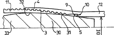
With reference to Fig. 8, the tube-shaped joint after the helical thread portion that the figure shows a pipe-shaped parts is screwed is used for carrying out diameter expansion according to the present invention.
This joint comprises male tubular part 11 and female tubular part 12 as shown in Figure 1.The end of male tubular part comprises flange 5, and when joint expanded, its circumferential surface 8 can enter the cloudy formula groove 8 of female tubular part 12, contacted with the circumferential surface 7 of cloudy formula groove 8.Have the contact area that merges contact between the expansion rear surface 7 and 8 and be called interior seal area CI, because it is in joint.Also there is the contact area between the apparent surface of the surface of a positive formula flange tongue piece and female tubular part groove after the expansion.
A tubular holders 36 is positioned on the female tubular part 12 in concentric mode.The internal diameter of this tubular holders 36 can be enclosed within this tubular holders on the female tubular part 12 operator before screwing pipe-shaped parts 11 and 12, and contacted with the outer surface 37 of pipe-shaped parts 12.This tubular holders extends on its whole length l m1, so that axially cover flange 5, and surpasses two sides of flange 5, promptly surpasses helical thread portion and tongue piece 13.Tubular holders 36 is preferably in centering on the flange.
Screw finish and expand before, tongue piece 13 axially is blocked in the bottom of groove 14, sealing surfaces 7 and 8 be a cylindricality, and mutual gap is very little when screwing end.Between the phase of expansion, flange 5 is kept by tongue piece 13/ groove 14 locking systems.
In this example, tubular holders 36 is made of with the pipe-shaped parts identical materials a kind of, and for example its limit of elasticity is identical with the limit of elasticity of these pipe-shaped parts.After the diameter expansion, tubular holders produces an elastic restoring force, and this elastic restoring force is added on the elastic restoring force of cloudy formula part, and resists the elastic return of positive formula part.Therefore realize the lock ring of cloudy formula part by tubular holders.In addition, the difference of the elastic return between the integral body of positive formula part and sleeve and cloudy formula part formation causes cloudy formula part compression.Because tubular holders 36 covering surfaces 7 and 8, and just over surface 7 and 8, the contact pressure of therefore compressing between the surface 7 and 8 that shows as positive formula part and cloudy formula part increases.Also realized the lock ring of cloudy formula part to positive formula part.The existence of tubular holders 36 is not only than there being tubular holders to need more energy (about 10%), but strengthened the contact pressure (sleeve that is 4-5mm to a thickness is about 200%) at seal area CI place in the back of expanding greatly.
In an illustrated embodiment, before the expansion, the formation of tubular holders 36 is as follows:
-overlay length lm1 equals flange length l approximately at least
1The maximum 2-8 that add a Width of thread of helical thread portion doubly;
-maximum radial the thickness and the radial thickness em1 of sleeve between the smallest radial thickness that the too little effect on the elastic return of thread part provides that are limited in that the maximum volume thickness of joint provides: for external diameter be about 150mm, thickness is the pipe-shaped parts of 7-8mm, radial thickness preferably is approximately several millimeters, for example be at least 1.5mm, and be preferably 4-5mm.The basic thickness of the recommendation thickness of sleeve near positive formula flange.The back radial thickness that expands equals 1mm at least.
In one embodiment of the invention, form the interior seal area CI of joint after 7 and 8 diameter expansion of surface.But another seal area is in the forward and backward formation of the diameter expansion of SEALING FITTING shown in Figure 8.
Therefore, comprise a cloudy formula flange 38 that does not have screw thread between the helical thread portion of female tubular part 12 and the free end.This cloudy formula flange 38 has an inner circumferential surface 41, and the end of inner circumferential surface 41 is radial surfaces 39 that form an annular surface.Male tubular part 11 has an external peripheral surface 40 on the next door of the male thread part relative with its free end.After sun formula and female tubular part were screwed fully, inner circumferential surface 41 radially interacted with the external peripheral surface 40 of male tubular part 11, so that form a seal area before expansion.The two all is taper for surface 40 and 41, and taper is similar.During expansion, cloudy formula flange axially is not blocked on the positive formula part, does not produce crooked and recurvate phenomenon as positive formula flanged shaft to the situation that is blocked in cloudy formula part.Therefore, cloudy formula flange does not have axially-extending.Only produce a cloudy formula flange 38 after the expansion than the big a little elastic return phenomenon of adjacent positive formula part.Sealing between the corresponding circumferential surface 40 of this inner circumferential surface 41 that causes cloudy formula flange and male tubular part 11 contacts.Contact when the interaction of screwing surface 40 and 41 when finishing can guarantee to expand the back elastic return between these two surfaces.
Sealing contact area between the expansion rear surface 40 and 41 is called external sealed district CE, because this seal area is outside joint.
Beyond what his method in office, the sealing that the external sealed that produces in the CE location always produces less than zone C I place.
A tubular holders 34 is positioned on the female tubular part 12 in concentric mode.The internal diameter of this tubular holders 34 can be enclosed within tubular holders 34 on the female tubular part 12 operator before screwing pipe-shaped parts 11,12, and tubular holders 34 is contacted with the outer surface 37 of pipe-shaped parts 12.This second tubular holders extends on its whole length l m2, so that axially covering can be at the circumferential surface 40 and 41 of forward and backward formation seal area that expands, and surpasses two sides on these surfaces, promptly at helical thread portion next door and radial surface 39 places.In this embodiment, tubular holders 34 is made of a kind of material of materials similar of and pipe-shaped parts, and for example its limit of elasticity equals the limit of elasticity of these pipe-shaped parts.After the diameter expansion, tubular holders produces an elastic restoring force, and this elastic restoring force is added on the restoring force of cloudy formula part, so that resist the elastic restoring force of positive formula part.Therefore realize the lock ring of cloudy formula part by tubular holders.In addition, the difference of the elastic return between the internal surface of sleeve and positive formula part causes cloudy formula part compression.Because tubular holders 34 covering surfaces 40 and 41, and just over surface 40 and 41, the contact pressure of therefore compressing between the sealing surfaces 40 and 41 that shows as positive formula part and cloudy formula part does not have the inipple of sleeve 34 to increase than one.Also realized the lock ring of cloudy formula part to positive formula part.The existence of tubular holders 34 is not only than there being tubular holders to need more energy, and strengthened the contact pressure (being about more than 300%) at the CE place, external sealed district, back of expanding greatly.
In an illustrated embodiment, before the expansion, the formation of tubular holders 34 is as follows:
The length that-overlay length lm2 equals cloudy formula flange 38 approximately at least add a screw thread of helical thread portion width maximum 2-8 doubly;
Radial thickness em2 between the smallest radial thickness that too little sleeve effect on the maximum radial thickness that-one maximum volume thickness that is limited to joint provides and the elastic return of a thread part provides: for external diameter be about 150mm, thickness is the pipe-shaped parts of 7-8mm, this radial thickness preferably is approximately several millimeters, for example be at least 1.5mm, and be preferably 4-5mm.The best thickness with cloudy formula flange of the recommendation thickness of sleeve 34 is the same order of magnitude.Radial thickness after the expansion equals 1mm at least.
No matter be sleeve 34 or 36, one positive relatively formulas of sleeve and cloudy formula thread part form short sleeve that material is interrupted than an additional long sleeve or on cloudy formula part simply thickened material replace sleeve to improve sealability, particularly external sealed greatly.
Also can consider other installation method of sleeve.
In one embodiment, a wherein end of tubular holders 34 comprises a radial projection 42.Therefore the operator was enclosed within tubular holders 34 on the pipe-shaped parts 12 from an end opposite with an end that comprises projection before screwing pipe-shaped parts 11 and 12, and the inner circumferential surface of sleeve contacts with external peripheral surface 37.Tubular holders 34 is nested into radial projection 42 always and contacts with radial surface 39.So tubular holders 34 axially locating.Radial projection 42 can also stick on the radial surface 39, so that improve contact pressure.Can use a kind of " grease-glue " that can under anaerobic in a few minutes, harden, and this " grease-glue " can keep when expanding tubular holders relative in place with cloudy formula part.The inflation process mesoglea may take place to shear or the crack, and what obstruction this does not have.
Implement in the modification at one, the operator screwing before tubular holders 36 or/34 be enclosed within on the pipe-shaped parts 12 then, then since female tubular part 12 outer circumferential surperficial 37 on mark of existence make the sleeve axially locating, mark can be a shallow slot.The same with the situation of the sleeve that has radial projection, can make tubular holders 36 and/or 34 keep axial position by " grease-glue ".Also can keep the axial position of tubular holders 36 and/or 34 by the very slight lock ring on the female tubular part.Lock ring can and/or cool off cloudy formula part and realize by heating muff.
The radial thickness of a tubular holders can reduce, and cost is that the effect of the enhanced leaktightness that produces of sleeve is relatively poor.But, can increase their the limit of elasticity loss of compensation sealing effect a little by the limit of elasticity of positive relatively formula and cloudy formula part 11,12 for thin sleeve.The limit of elasticity of sleeve must be many more than the limit of elasticity height of Yang Shi and cloudy formula part, and the sealing on certain thickness is good more.The limit of elasticity of tubular holders can improve by heat treatment.But increase the ductility that limit of elasticity generally can reduce material.Can between enough ductility and enough limit of elasticity, find a kind of compromise, enough ductility is in order to produce expansion, and sleeve is broken, although sufficiently high limit of elasticity is to guarantee enough sealabilities for the radial thickness of tubular holders is limited.
If a pipe-shaped parts includes only an external sealed district CE or interior seal area CI, this seal area can guarantee that fluid from inside to outside and sealing from outside to inside.In this case, " external sealed district " and " interior seal area " mainly is the seal area that is positioned at Yang Shi or female tubular part free end.
Annex I has enumerated the relative performance aspect the comprehensive contact pressure of inipple on contact width.The purpose of this research is relative one and simply with reference to inipple (case 1) different embodiments according to the invention and this simple inipple is compared.With reference to joint is that an external diameter is the inipple of 152.4mm (6 inches), proportion is 27.8kg/m (18.6 pounds/foot), AISI420 steel with U.S.'s title is made (13% chromium, be equivalent to European title X20Cr13), handle (API=API) through APIL80, being equivalent to the minimal elastic limit is 551MPa.
Table 1,2 relates separately to the result of outer, interior sealing percentage of the interior sealing of each case relative reference case of being considered:
-case 1: with reference to inipple;
-case 2: on positive formula thread part, cover a very reference inipple of long sleeve, and sleeve covers the helical thread portion of positive formula and cloudy formula flange, thickness is 4.5mm, makes by the steel identical (13% chromium) with inipple, and through the processing (API L80) identical with joint;
-case 3: be provided with the reference inipple of two short sleeves according to the invention (Fig. 8), thickness, material and processing are identical with the case of front;
-case 4: identical with case 3, but include only extremely thin (thickness 1.6mm) sleeve that is positioned at cloudy formula flange place, and sleeve is attached on the cloudy formula part at its radial projection place.
-case 5: identical with case 4, but comprise that 110 grades of processing of a process API P (are equivalent to limit of elasticity R
P0.2〉=758MPa) sleeve.
In case 1, interior sealing is outstanding, but external sealed relatively poor (44% interior sealing).A long sleeve (case 2) has only improved interior sealing.Use two thickness and case 2 similar short sleeves (case 3) to improve external sealed and interior sealing simultaneously.Reduce thickness (case 4) greatly and can keep enough external sealeds (having only a research).Improving the rank of sleeve, therefore is to improve limit of elasticity (case 5) can improve sealing, and sealing almost reaches the level of reference case.
To diameter expansion and expansion energy, the spike effect very limited (not showing here) that exists sleeve to produce.
For a pipe-shaped parts that has in two sealing and external sealed district, the enforcement modification of a tubular holders is made of a tubular as shown in figure 11 cap piece 45, cap piece 45 comprises the sleeve 34 and 36 of Fig. 8, is connected to each other by a tubular spacer body 46 between the sleeve 34 and 36.The radial thickness of this spacer body 46 is more much smaller than the radial thickness of sleeve 34 and 36, so as on the whole length of spacer body 46 in fact non resistance diameter expansion power.
The different installation methods of this cap piece are identical with the method for an independent tubular holders 34.
The present invention is not limited to the embodiment who describes as an example.
The present invention or be used to have only the joint of interior seal area perhaps is used for only having the joint in external sealed district, perhaps is used for having or another joint of seal area.The present invention can be used to have the joint of other seal area, for example has the joint in intermediate seal district.
Annex
Table 1
| The case numbering | 1 | 2 | 3 | 4 | 5 |
| External sealed (with the percentage of sealing in the case 1) | 44 | 42 | 158 | 89 | 99 |
Table 2
| The case numbering | 1 | 2 | 3 |
| Interior sealing (with the percentage of sealing in the case 1) | 100 | 220 | 201 |
Claims (19)
1. high-performance screwed pipe joint, it comprises one first male tubular part (11) and one second female tubular part (12), what they can be by the helical thread portion that respectively carries screws mutual assembling, the described first positive formula and second female tubular part (11; 12) at least one in comprises a no threaded-on flange (38; 5), described flange extends between its helical thread portion and its free end, and has a sealing surfaces (40; 7), described sealing surfaces screw, the elastic restoring force of diameter expansion and the described subsequently first positive formula and second female tubular part produce after can with the apparent surface (41 of another part; 8) sealing contact,
Described joint is characterised in that described joint comprises a tubular holders (34; 36), described tubular holders (34; 36) can screw protheca on described second female tubular part (12), and can be positioned, so as with described flange (38; 5) relatively extend axially substantially, and can be after diameter expansion, produce an elastic restoring force, described elastic restoring force superposition is on the elastic restoring force of second female tubular part, so that resist the elastic restoring force of described first male tubular part, therefore by the lock ring of described tubular holders realization at least the second female tubular part.
2. pipe joint as claimed in claim 1, it is characterized in that, the no threaded-on flange (5) of described first male tubular part comprises an end tongue piece, described tongue piece can be bonded on to axial stop in the corresponding recesses of described second female tubular part before screwing the back and expanding, in the process of diameter expansion, described no threaded-on flange can remain in the described groove by described tongue piece.
3. each described pipe joint as in the above-mentioned claim is characterized in that the sealing surfaces of described flange and described apparent surface be cylindricality, and a little gap is arranged between mutual before screwing back and diameter expansion.
4. pipe joint as claimed in claim 1 is characterized in that, the sealing surfaces of described flange and described apparent surface be radial effect mutually before screwing back and diameter expansion.
5. as each described pipe joint in claim 1-2 and 4, it is characterized in that, in the described first positive formula and second female tubular part (11,12) each comprises that one extends in its helical thread portion and the no threaded-on flange between its free end (38,5), and described no threaded-on flange (38,5) has a sealing surfaces (40,7), described sealing surfaces screw, the elastic restoring force of diameter expansion and the described subsequently first positive formula and second female tubular part can contact with apparent surface (41, the 8) sealing of another part after producing; And, described joint comprises two tubular holders (34,36), described tubular holders (34,36) can be enclosed within before screwing on described second female tubular part (12), and be positioned so that extend axially substantially with respect to corresponding flange (38,5), and produce an elastic restoring force, described elastic restoring force superposition is on the elastic restoring force of described second female tubular part, so that resist the elastic restoring force of described first male tubular part, therefore by the lock ring of described tubular holders realization to described at least second female tubular part.
6. pipe joint as claimed in claim 5, it is characterized in that, described two sleeves (34,36) are connected to each other by a spacer body (46), and the cross section of described spacer body (46) is less than the cross section of described sleeve, and described sleeve and described spacer body are made a single component.
7. pipe joint as claimed in claim 6 is characterized in that, the radial thickness of described tubular spacer body (46) is less than the radial thickness of described sleeve.
8. as each described pipe joint in claim 1-2 and 4, it is characterized in that each tubular holders (34; 36) overlay length (lm1; Lm2) equal the length of described opposing flanges, the length that perhaps equals described opposing flanges adds maximum eight pitch of the above helical thread portion.
9. pipe joint as claimed in claim 8 is characterized in that, each sleeve (34; 36) in described opposing flanges (38; 5) go up centering.
10. as each described pipe joint in claim 1-2 and 4, it is characterized in that, comprise a radial projection (42) with the tubular holders (34) of the relative extension of flange (38) of described second female tubular part, described radial projection (42) can contact with a radial surface (39) that is positioned at described second female tubular part (12) end and can be convenient to the in place of described tubular holders (34).
11., it is characterized in that described tubular holders (34 as each described pipe joint in claim 1-2 and 4; 36) part surface by bonding described second female tubular part (12) and described sleeve is held in place with respect to described second female tubular part (12).
12., it is characterized in that described tubular holders (34 as each described pipe joint in claim 1-2 and 4; 36) go up axially locating by lock ring at described second female tubular part (12), described lock ring is the cooling realization by described second female tubular part (12) at least.
13., it is characterized in that described tubular holders (34 as each described pipe joint in claim 1-2 and 4; 36) go up axially locating by lock ring at described second female tubular part (12), described lock ring is realized by the heating of described tubular holders at least.
14., it is characterized in that described second female tubular part (12) comprises that one is positioned at the mark on its external peripheral surface (37), and described mark can be beneficial to the in place of described tubular holders as each described pipe joint in claim 1-2 and 4.
15. pipe joint as claimed in claim 14 is characterized in that, described mark is a shallow slot of making on described second female tubular part (12).
16., it is characterized in that the radial thickness of described tubular holders equals 1.5mm at least as each described pipe joint in claim 1-2 and 4.
17., it is characterized in that described tubular holders elastic limit of materials is the tubular and second female tubular part elastic limit of materials greater than the described first positive formula as each described pipe joint in claim 1-2 and 4.
18., it is characterized in that the elastic limit of materials of described tubular holders is regulated by heat treatment as each described pipe joint in claim 1-2 and 4.
19. realize the method for sealing threaded pipe joints, it is characterized in that, from a screwed pipe joint that meets one of aforesaid right requirement---described joint is called " original screwed pipe joint "; And make described original screwed pipe joint bear a diameter expansion in the plastic deformation scope greater than the expansion spheroid (30) of described pipe-shaped parts internal diameter (DI) by a diameter, described spheroid (30) moves axially in described inipple, produce an elastic restoring force behind each sleeve expansion, the regional superposition that described elastic restoring force covers at described sleeve is on the elastic restoring force of described second female tubular part.
Applications Claiming Priority (2)
| Application Number | Priority Date | Filing Date | Title |
|---|---|---|---|
| FR02/08080 | 2002-06-28 | ||
| FR0208080A FR2841626B1 (en) | 2002-06-28 | 2002-06-28 | REINFORCED TUBULAR THREADED JOINT FOR IMPROVED SEALING AFTER PLASTIC EXPANSION |
Publications (2)
| Publication Number | Publication Date |
|---|---|
| CN1666056A CN1666056A (en) | 2005-09-07 |
| CN100482998C true CN100482998C (en) | 2009-04-29 |
Family
ID=29724970
Family Applications (1)
| Application Number | Title | Priority Date | Filing Date |
|---|---|---|---|
| CNB038153033A Expired - Fee Related CN100482998C (en) | 2002-06-28 | 2003-06-11 | Reinforced tubular threaded joint for improved sealing after plastic expansion |
Country Status (20)
| Country | Link |
|---|---|
| US (1) | US7581766B2 (en) |
| EP (1) | EP1518068B1 (en) |
| JP (1) | JP4234100B2 (en) |
| CN (1) | CN100482998C (en) |
| AR (1) | AR040307A1 (en) |
| AT (1) | ATE360778T1 (en) |
| AU (1) | AU2003255659B2 (en) |
| BR (1) | BR0312117B1 (en) |
| CA (1) | CA2489516C (en) |
| DE (1) | DE60313460T2 (en) |
| EA (1) | EA006214B1 (en) |
| EG (1) | EG23594A (en) |
| FR (1) | FR2841626B1 (en) |
| MX (1) | MXPA05000026A (en) |
| MY (1) | MY137063A (en) |
| NO (1) | NO20050243L (en) |
| OA (1) | OA12828A (en) |
| PL (1) | PL207609B1 (en) |
| UA (1) | UA79618C2 (en) |
| WO (1) | WO2004003416A1 (en) |
Families Citing this family (48)
| Publication number | Priority date | Publication date | Assignee | Title |
|---|---|---|---|---|
| US7357188B1 (en) | 1998-12-07 | 2008-04-15 | Shell Oil Company | Mono-diameter wellbore casing |
| US7775290B2 (en) | 2003-04-17 | 2010-08-17 | Enventure Global Technology, Llc | Apparatus for radially expanding and plastically deforming a tubular member |
| US7546881B2 (en) | 2001-09-07 | 2009-06-16 | Enventure Global Technology, Llc | Apparatus for radially expanding and plastically deforming a tubular member |
| US7793721B2 (en) | 2003-03-11 | 2010-09-14 | Eventure Global Technology, Llc | Apparatus for radially expanding and plastically deforming a tubular member |
| FR2844331B1 (en) * | 2002-01-03 | 2004-11-26 | Vallourec Mannesmann Oil & Gas | PROCESS FOR PRODUCING A SEALED TUBULAR JOINT WITH PLASTIC EXPANSION |
| US7918284B2 (en) | 2002-04-15 | 2011-04-05 | Enventure Global Technology, L.L.C. | Protective sleeve for threaded connections for expandable liner hanger |
| WO2003086675A2 (en) | 2002-04-12 | 2003-10-23 | Enventure Global Technology | Protective sleeve for threaded connections for expandable liner hanger |
| AU2003265452A1 (en) | 2002-09-20 | 2004-04-08 | Enventure Global Technology | Pipe formability evaluation for expandable tubulars |
| US7886831B2 (en) | 2003-01-22 | 2011-02-15 | Enventure Global Technology, L.L.C. | Apparatus for radially expanding and plastically deforming a tubular member |
| GB2429224B (en) * | 2003-02-18 | 2007-11-28 | Enventure Global Technology | Protective compression and tension sleeves for threaded connections for radially expandable tubular members |
| US20080136181A1 (en) * | 2003-02-18 | 2008-06-12 | Enventure Global Technology | Protective Compression and Tension Sleeves for Threaded Connections for Radially Expandable Tubular Members |
| GB0313472D0 (en) * | 2003-06-11 | 2003-07-16 | Weatherford Lamb | Tubing connector |
| GB0317395D0 (en) * | 2003-07-25 | 2003-08-27 | Weatherford Lamb | Sealing expandable tubing |
| GB0317547D0 (en) * | 2003-07-26 | 2003-08-27 | Weatherford Lamb | Sealing tubing |
| US7712522B2 (en) | 2003-09-05 | 2010-05-11 | Enventure Global Technology, Llc | Expansion cone and system |
| FR2863029B1 (en) * | 2003-11-28 | 2006-07-07 | Vallourec Mannesmann Oil & Gas | REALIZATION, BY PLASTIC EXPANSION, OF A SEALED TUBULAR JOINT WITH INITIAL LOCAL SENSITIZER (S) (S) |
| FR2863033B1 (en) * | 2003-11-28 | 2007-05-11 | Vallourec Mannesmann Oil & Gas | REALIZATION, BY PLASTIC EXPANSION, OF A SEALED TUBULAR JOINT WITH INCLINED STRAINING SURFACE (S) |
| WO2005113190A1 (en) | 2004-04-21 | 2005-12-01 | Grant Prideco, L.P. | Method and apparatus for sealing radially expanded joints |
| US7585002B2 (en) * | 2004-04-21 | 2009-09-08 | Baker Hughes Incorporated | Expandable tubular connection |
| US7819185B2 (en) | 2004-08-13 | 2010-10-26 | Enventure Global Technology, Llc | Expandable tubular |
| FR2874988B1 (en) | 2004-09-09 | 2008-05-02 | Vallourec Mannesmann Oil & Gas | MALE ELEMENT FOR A TUBULAR THREADED SEAL AFTER DIAMETER EXPANSION |
| US7798536B2 (en) * | 2005-08-11 | 2010-09-21 | Weatherford/Lamb, Inc. | Reverse sliding seal for expandable tubular connections |
| US20070035132A1 (en) * | 2005-08-11 | 2007-02-15 | Grinaldi Ltd | Expandable tubular connection |
| US20070035131A1 (en) * | 2005-08-11 | 2007-02-15 | Grinaldi Ltd | Expandable tubular connection |
| US20070035127A1 (en) * | 2005-08-12 | 2007-02-15 | Benzie Scott A | Protective sleeve for tubular connection |
| US7549682B2 (en) * | 2005-09-19 | 2009-06-23 | Vetco Gray Inc. | Threaded pipe connector |
| CA2625585A1 (en) * | 2005-10-11 | 2007-04-26 | Enventure Global Technology, L.L.C. | Method and apparatus for coupling expandable tubular members |
| FR2895485B1 (en) * | 2005-12-23 | 2012-04-13 | Vallourec Mannesmann Oil & Gas | EXTERNAL PROTECTION OF TUBULAR THREADED JOINTS FOR EXPANDING |
| WO2008047378A2 (en) * | 2006-01-30 | 2008-04-24 | Tema India Limited | A process of fitting a shrink ring |
| US20100225107A1 (en) * | 2006-02-17 | 2010-09-09 | Norsk Hydro Asa | Gas Tight Tubular Joint or Connection |
| EP2267268A3 (en) * | 2006-05-22 | 2016-03-23 | Weatherford Technology Holdings, LLC | Apparatus and methods to protect connections |
| GB0610987D0 (en) * | 2006-06-03 | 2006-07-12 | Elmar Services Ltd | Method and Apparatus |
| FR2904031B1 (en) * | 2006-07-20 | 2014-03-07 | Vallourec Mannesmann Oil & Gas | MALE ELEMENT FOR A DRILLING COMPONENT WITH EXTERNAL STOP AND INTERNAL STOP ADAPTED TO THE LENGTH WITHOUT LOSS OF RESISTANCE TORQUE, AND ASSOCIATED DRILLING COMPONENT ASSEMBLY. |
| WO2008097224A1 (en) * | 2007-02-08 | 2008-08-14 | Mohawk Energy Ltd. | Protective sleeve for tubular connection |
| FR2912730B1 (en) * | 2007-02-21 | 2012-07-06 | Vallourec Mannesmann Oil & Gas France | DEVICE FOR PROTECTING A FEMALE END OF A TUBULAR JOINT COMPONENT WITH ANTI-CUT-OFF BRAKE. |
| FR2954453B1 (en) * | 2009-12-23 | 2012-03-09 | Vallourec Mannesmann Oil & Gas | ASSEMBLY FOR CARRYING OUT A THREADED SEAL, METHOD FOR SCREWING AND DISCRIMINATING SUCH A SEAL AND USE OF SUCH JOINT IN AN UNDERWATER UPLINK |
| FR2956466B1 (en) | 2010-02-17 | 2012-06-08 | Vallourec Mannesmann Oil & Gas | EXPANDABLE THREAD JOINT AND METHOD OF MAKING SAME |
| JP5665653B2 (en) * | 2011-05-23 | 2015-02-04 | エヌケーケーシームレス鋼管株式会社 | Double shoulder type tool joint |
| FR2984395B1 (en) | 2011-12-19 | 2013-12-27 | Vallourec Mannesmann Oil & Gas | TUBULAR COMPONENT FOR DRILLING AND OPERATING HYDROCARBON WELLS AND RESULTING THREAD |
| AT511801B1 (en) * | 2012-02-07 | 2013-03-15 | Bosch Gmbh Robert | METHOD FOR INFLUENCING THE THREADED GEOMETRY OF AN INTERNAL THREAD FOR INTERNAL COMBUSTION ENGINES |
| KR101475938B1 (en) * | 2013-05-14 | 2014-12-23 | (주)복바우 | The connecting structure of corrugated pipe |
| EP3126610B1 (en) | 2014-04-04 | 2021-01-06 | Enventure Global Technology, L.L.C. | Expandable metal-to-metal seal connection |
| JP6493789B2 (en) * | 2015-03-03 | 2019-04-03 | 日立金属株式会社 | Die casting sleeve |
| US10648299B2 (en) * | 2015-07-01 | 2020-05-12 | Shell Oil Company | Expanding well tubulars interconnected by pin-box assemblies optimized for expansion |
| FR3040731B1 (en) * | 2015-09-07 | 2017-09-08 | Vallourec Oil & Gas France | PRESSURE TEST CAP FOR SUPERIOR TUBULAR THREAD COMPONENT |
| CA3062427A1 (en) | 2017-05-12 | 2018-11-15 | Ultra Premium Services, L.L.C. | Curvilinear sealing system |
| US11473702B1 (en) * | 2019-04-10 | 2022-10-18 | Benoit Premium Threading, Llc | Integral expanded upset |
| EP4328412A1 (en) * | 2022-08-25 | 2024-02-28 | Sandvik Mining and Construction Tools AB | End piece of drill pipe, drill pipe assembly and method |
Citations (3)
| Publication number | Priority date | Publication date | Assignee | Title |
|---|---|---|---|---|
| US4611838A (en) * | 1982-02-27 | 1986-09-16 | Mannesmann Aktiengesellschaft | Fluidtight pipe joint |
| WO2000008301A2 (en) * | 1998-08-08 | 2000-02-17 | Weatherford/Lamb, Inc. | Connector for expandable well screen |
| WO2002001102A1 (en) * | 2000-06-30 | 2002-01-03 | Vallourec Mannesmann Oil & Gas France | Tubular threaded joint capable of being subjected to diametral expansion |
Family Cites Families (43)
| Publication number | Priority date | Publication date | Assignee | Title |
|---|---|---|---|---|
| US418752A (en) * | 1890-01-07 | Device for sealing the joints of gas-pipes | ||
| US733346A (en) * | 1902-12-22 | 1903-07-07 | Tallerday Steel Pipe & Tank Company | Pipe connection. |
| US1942518A (en) * | 1933-06-22 | 1934-01-09 | Pittsburgh Steel Co | Pipe joint |
| US2592854A (en) * | 1946-02-08 | 1952-04-15 | Reed Roller Bit Co | Tool joint wear sleeve |
| US2546295A (en) * | 1946-02-08 | 1951-03-27 | Reed Roller Bit Co | Tool joint wear collar |
| US2978263A (en) * | 1954-01-11 | 1961-04-04 | Mulconroy Company | Hose coupling having deformable sleeve with extrusion holes |
| US3015500A (en) * | 1959-01-08 | 1962-01-02 | Dresser Ind | Drill string joint |
| US3191677A (en) * | 1963-04-29 | 1965-06-29 | Myron M Kinley | Method and apparatus for setting liners in tubing |
| FR1489013A (en) | 1965-11-05 | 1967-07-21 | Vallourec | Assembly joint for metal pipes |
| US3545794A (en) * | 1969-05-06 | 1970-12-08 | Sloane Mfg Co R & G | Compression joint |
| US3674292A (en) * | 1969-10-15 | 1972-07-04 | Amp Inc | Tubular connection devices |
| US3942824A (en) * | 1973-11-12 | 1976-03-09 | Sable Donald E | Well tool protector |
| FR2359353A1 (en) | 1976-07-23 | 1978-02-17 | Vallourec | SEAL FOR TUBES, ESPECIALLY FOR OIL TUBES |
| DE3887905D1 (en) * | 1988-11-22 | 1994-03-24 | Tatarskij Gni Skij I Pi Neftja | EXPANDING TOOL FOR TUBES. |
| US5015014A (en) * | 1989-06-19 | 1991-05-14 | Aardvark Corporation, Inc. | Plastic pipe section |
| US5137310A (en) | 1990-11-27 | 1992-08-11 | Vallourec Industries | Assembly arrangement using frustoconical screwthreads for tubes |
| MY108743A (en) * | 1992-06-09 | 1996-11-30 | Shell Int Research | Method of greating a wellbore in an underground formation |
| GB2287996B (en) * | 1994-03-22 | 1997-08-06 | British Gas Plc | Joining thermoplastic pipe to a coupling |
| FR2725773B1 (en) * | 1994-10-13 | 1996-11-29 | Vallourec Oil & Gas | THREADED ASSEMBLY FOR TUBES |
| US5582439A (en) * | 1995-06-07 | 1996-12-10 | Spears Manufacturing Company | Strengthened pipe fitting and method |
| US6047997A (en) * | 1996-05-15 | 2000-04-11 | Iberia Threading, Inc. | Threaded connection with radiused surfaces |
| MY116920A (en) | 1996-07-01 | 2004-04-30 | Shell Int Research | Expansion of tubings |
| FR2761450B1 (en) * | 1997-03-27 | 1999-05-07 | Vallourec Mannesmann Oil & Gas | THREADED JOINT FOR TUBES |
| MY122241A (en) | 1997-08-01 | 2006-04-29 | Shell Int Research | Creating zonal isolation between the interior and exterior of a well system |
| JP4085403B2 (en) | 1997-12-31 | 2008-05-14 | シエル・インターナシヨネイル・リサーチ・マーチヤツピイ・ベー・ウイ | Drilling and finishing methods for hydrocarbon production wells |
| FR2776746B1 (en) * | 1998-03-26 | 2000-04-28 | Vallourec Mannesmann Oil & Gas | THREADED ASSEMBLY OF METAL TUBES FOR CONTAINING A FLUID |
| US6305723B1 (en) * | 1998-10-27 | 2001-10-23 | Grant Prideco, L.P. | Tool joint and drill pipe made therefrom |
| DE60003651T2 (en) | 1999-04-09 | 2004-06-24 | Shell Internationale Research Maatschappij B.V. | METHOD FOR PRODUCING A HOLE IN A SUBSTRATE INFORMATION |
| US6409175B1 (en) * | 1999-07-13 | 2002-06-25 | Grant Prideco, Inc. | Expandable joint connector |
| US6564875B1 (en) * | 1999-10-12 | 2003-05-20 | Shell Oil Company | Protective device for threaded portion of tubular member |
| US6554287B1 (en) * | 1999-12-09 | 2003-04-29 | Hydril Company | Collapsing type seal for expandable tubular connections |
| US6619696B2 (en) * | 2001-12-06 | 2003-09-16 | Baker Hughes Incorporated | Expandable locking thread joint |
| FR2844330B1 (en) | 2002-01-03 | 2005-05-13 | Vallourec Mannesmann Oil & Gas | IMPROVED TUBULAR THREAD SEAL AFTER PLASTIC EXPANSION |
| FR2834325B1 (en) | 2002-01-03 | 2004-03-26 | Vallourec Mannesmann Oil & Gas | TUBULAR THREADED JOINT HAVING SEALING SURFACES |
| FR2844331B1 (en) | 2002-01-03 | 2004-11-26 | Vallourec Mannesmann Oil & Gas | PROCESS FOR PRODUCING A SEALED TUBULAR JOINT WITH PLASTIC EXPANSION |
| CN101131070A (en) * | 2002-01-07 | 2008-02-27 | 亿万奇环球技术公司 | Protective sleeve for threaded connections for expandable liner hanger |
| WO2003086675A2 (en) | 2002-04-12 | 2003-10-23 | Enventure Global Technology | Protective sleeve for threaded connections for expandable liner hanger |
| US7918284B2 (en) | 2002-04-15 | 2011-04-05 | Enventure Global Technology, L.L.C. | Protective sleeve for threaded connections for expandable liner hanger |
| AU2003249371A1 (en) | 2002-07-19 | 2004-02-09 | Enventure Global Technology | Protective sleeve for threaded connections for expandable liner hanger |
| US20060113085A1 (en) | 2002-07-24 | 2006-06-01 | Scott Costa | Dual well completion system |
| AU2003298954A1 (en) | 2002-09-20 | 2004-03-29 | Enventure Global Technlogy | Threaded connection for expandable tubulars |
| AU2003263859A1 (en) | 2002-09-20 | 2004-04-08 | Enventure Global Technology | Protective sleeve for expandable tubulars |
| GB2429224B (en) | 2003-02-18 | 2007-11-28 | Enventure Global Technology | Protective compression and tension sleeves for threaded connections for radially expandable tubular members |
-
2002
- 2002-06-28 FR FR0208080A patent/FR2841626B1/en not_active Expired - Fee Related
-
2003
- 2003-06-05 MY MYPI20032101A patent/MY137063A/en unknown
- 2003-06-11 BR BRPI0312117-8A patent/BR0312117B1/en not_active IP Right Cessation
- 2003-06-11 AT AT03761614T patent/ATE360778T1/en active
- 2003-06-11 DE DE60313460T patent/DE60313460T2/en not_active Expired - Lifetime
- 2003-06-11 CA CA2489516A patent/CA2489516C/en not_active Expired - Fee Related
- 2003-06-11 EP EP03761614A patent/EP1518068B1/en not_active Expired - Lifetime
- 2003-06-11 CN CNB038153033A patent/CN100482998C/en not_active Expired - Fee Related
- 2003-06-11 PL PL372821A patent/PL207609B1/en unknown
- 2003-06-11 AU AU2003255659A patent/AU2003255659B2/en not_active Ceased
- 2003-06-11 EA EA200500102A patent/EA006214B1/en not_active IP Right Cessation
- 2003-06-11 JP JP2004516838A patent/JP4234100B2/en not_active Expired - Fee Related
- 2003-06-11 OA OA1200400346A patent/OA12828A/en unknown
- 2003-06-11 US US10/496,008 patent/US7581766B2/en not_active Expired - Fee Related
- 2003-06-11 MX MXPA05000026A patent/MXPA05000026A/en active IP Right Grant
- 2003-06-11 WO PCT/FR2003/001744 patent/WO2004003416A1/en active IP Right Grant
- 2003-06-27 AR ARP030102347A patent/AR040307A1/en active IP Right Grant
- 2003-11-06 UA UAA200500742A patent/UA79618C2/en unknown
-
2004
- 2004-12-26 EG EGNA2004000152 patent/EG23594A/en active
-
2005
- 2005-01-17 NO NO20050243A patent/NO20050243L/en not_active Application Discontinuation
Patent Citations (3)
| Publication number | Priority date | Publication date | Assignee | Title |
|---|---|---|---|---|
| US4611838A (en) * | 1982-02-27 | 1986-09-16 | Mannesmann Aktiengesellschaft | Fluidtight pipe joint |
| WO2000008301A2 (en) * | 1998-08-08 | 2000-02-17 | Weatherford/Lamb, Inc. | Connector for expandable well screen |
| WO2002001102A1 (en) * | 2000-06-30 | 2002-01-03 | Vallourec Mannesmann Oil & Gas France | Tubular threaded joint capable of being subjected to diametral expansion |
Also Published As
| Publication number | Publication date |
|---|---|
| FR2841626A1 (en) | 2004-01-02 |
| DE60313460T2 (en) | 2008-01-03 |
| WO2004003416A1 (en) | 2004-01-08 |
| JP2005536691A (en) | 2005-12-02 |
| BR0312117A (en) | 2005-03-29 |
| ATE360778T1 (en) | 2007-05-15 |
| NO20050243L (en) | 2005-01-17 |
| US20050087983A1 (en) | 2005-04-28 |
| OA12828A (en) | 2006-07-11 |
| JP4234100B2 (en) | 2009-03-04 |
| EA200500102A1 (en) | 2005-06-30 |
| PL207609B1 (en) | 2011-01-31 |
| UA79618C2 (en) | 2007-07-10 |
| CN1666056A (en) | 2005-09-07 |
| EG23594A (en) | 2006-09-21 |
| AU2003255659B2 (en) | 2008-01-10 |
| FR2841626B1 (en) | 2004-09-24 |
| EP1518068A1 (en) | 2005-03-30 |
| PL372821A1 (en) | 2005-08-08 |
| EP1518068B1 (en) | 2007-04-25 |
| AU2003255659A1 (en) | 2004-01-19 |
| CA2489516A1 (en) | 2004-01-08 |
| BR0312117B1 (en) | 2014-09-09 |
| US7581766B2 (en) | 2009-09-01 |
| EA006214B1 (en) | 2005-10-27 |
| CA2489516C (en) | 2011-05-10 |
| AR040307A1 (en) | 2005-03-23 |
| MY137063A (en) | 2008-12-31 |
| DE60313460D1 (en) | 2007-06-06 |
| MXPA05000026A (en) | 2005-04-08 |
Similar Documents
| Publication | Publication Date | Title |
|---|---|---|
| CN100482998C (en) | Reinforced tubular threaded joint for improved sealing after plastic expansion | |
| CN100392309C (en) | Method for making a sealed tubular joint with plastic expansion | |
| CN100395474C (en) | Expandable joint connector | |
| US8567492B2 (en) | Modified packer with non-extrusion ring | |
| CN101087926B (en) | expansion pig | |
| EP1601904B1 (en) | Method for producing a threaded tubular connection sealed by radial expansion | |
| CN101187296A (en) | Protective sleeve for threaded connections for expandable liner hanger | |
| CN206681760U (en) | Deep hole grouting device after shield duct piece wall | |
| JP4740869B2 (en) | Fittings and methods for producing fittings | |
| JP4842136B2 (en) | Fittings and methods for producing fittings | |
| US20200277836A1 (en) | Buckle prevention ring | |
| CN101432499B (en) | Gas tight tubular joint or connection | |
| WO2011056429A1 (en) | Threaded pipe connection with a pressure energized flex-seal | |
| US8146960B2 (en) | Two hermetic threaded tubular joints | |
| CN104453729A (en) | Combined aluminum alloy double-wall drill pipe unit | |
| CN108953759B (en) | Self-balancing bidirectional pipe replacement and repair method and device | |
| US4444400A (en) | Seal assemblies and corrugated metal packer members therefor | |
| CN104563954A (en) | Steel pipe expansion recovery type external casing packer | |
| US2775472A (en) | Sealing device for flanged joints | |
| CN1087968A (en) | Ring seal packer | |
| CN104321502A (en) | Pipe provided with a crimped metal element, and corresponding process | |
| CN115434657A (en) | Skeleton type telescopic sealing device, packer and application | |
| CN111577192B (en) | Orifice pressure-bearing sealing device for underground coal mine water prevention and control composite directional drilling | |
| MX2015000498A (en) | High pressure seal back-up. | |
| CN209818038U (en) | Gas-liquid double-flow injection allocation tool |
Legal Events
| Date | Code | Title | Description |
|---|---|---|---|
| C06 | Publication | ||
| PB01 | Publication | ||
| C10 | Entry into substantive examination | ||
| SE01 | Entry into force of request for substantive examination | ||
| C14 | Grant of patent or utility model | ||
| GR01 | Patent grant | ||
| C56 | Change in the name or address of the patentee |
Owner name: VALLOUREC PETROLEUM AND GAS SAS Free format text: FORMER NAME: VALLOUREC MANNESMANN OIL + GAS |
|
| CP01 | Change in the name or title of a patent holder |
Address after: French aulnois aimeries Patentee after: VALLOUREC MANNESMANN OIL & GAS FRANCE Address before: French aulnois aimeries Patentee before: Vallourec Mannesmann Oil and Gas France Company |
|
| CF01 | Termination of patent right due to non-payment of annual fee | ||
| CF01 | Termination of patent right due to non-payment of annual fee |
Granted publication date: 20090429 Termination date: 20160611 |