JP4234100B2 - Reinforced tubular joints for improving hermeticity after plastic expansion - Google Patents
Reinforced tubular joints for improving hermeticity after plastic expansion Download PDFInfo
- Publication number
- JP4234100B2 JP4234100B2 JP2004516838A JP2004516838A JP4234100B2 JP 4234100 B2 JP4234100 B2 JP 4234100B2 JP 2004516838 A JP2004516838 A JP 2004516838A JP 2004516838 A JP2004516838 A JP 2004516838A JP 4234100 B2 JP4234100 B2 JP 4234100B2
- Authority
- JP
- Japan
- Prior art keywords
- tubular
- female
- sleeve
- threaded
- lip
- Prior art date
- Legal status (The legal status is an assumption and is not a legal conclusion. Google has not performed a legal analysis and makes no representation as to the accuracy of the status listed.)
- Expired - Fee Related
Links
- 238000007789 sealing Methods 0.000 claims description 29
- 239000000463 material Substances 0.000 claims description 16
- 238000000034 method Methods 0.000 claims description 16
- 238000010438 heat treatment Methods 0.000 claims description 6
- 239000000853 adhesive Substances 0.000 claims description 4
- 230000001070 adhesive effect Effects 0.000 claims description 4
- 238000005304 joining Methods 0.000 claims description 4
- 238000001816 cooling Methods 0.000 claims description 3
- 238000005452 bending Methods 0.000 description 28
- 238000007906 compression Methods 0.000 description 8
- 230000006835 compression Effects 0.000 description 8
- 239000002184 metal Substances 0.000 description 8
- 229910052751 metal Inorganic materials 0.000 description 8
- 230000008569 process Effects 0.000 description 8
- 230000008878 coupling Effects 0.000 description 7
- 238000010168 coupling process Methods 0.000 description 7
- 238000005859 coupling reaction Methods 0.000 description 7
- 239000004519 grease Substances 0.000 description 6
- 238000005553 drilling Methods 0.000 description 5
- 230000000694 effects Effects 0.000 description 5
- 239000012530 fluid Substances 0.000 description 5
- 239000007789 gas Substances 0.000 description 5
- 239000007788 liquid Substances 0.000 description 5
- 230000008901 benefit Effects 0.000 description 4
- 229930195733 hydrocarbon Natural products 0.000 description 4
- 150000002430 hydrocarbons Chemical class 0.000 description 4
- 230000002829 reductive effect Effects 0.000 description 4
- 239000004215 Carbon black (E152) Substances 0.000 description 3
- 229910000831 Steel Inorganic materials 0.000 description 3
- 238000003825 pressing Methods 0.000 description 3
- 239000010959 steel Substances 0.000 description 3
- 238000006243 chemical reaction Methods 0.000 description 2
- 230000000670 limiting effect Effects 0.000 description 2
- 230000035515 penetration Effects 0.000 description 2
- 230000002093 peripheral effect Effects 0.000 description 2
- 239000003208 petroleum Substances 0.000 description 2
- 230000009467 reduction Effects 0.000 description 2
- 230000002787 reinforcement Effects 0.000 description 2
- 230000003014 reinforcing effect Effects 0.000 description 2
- 230000000717 retained effect Effects 0.000 description 2
- 238000011144 upstream manufacturing Methods 0.000 description 2
- XLYOFNOQVPJJNP-UHFFFAOYSA-N water Substances O XLYOFNOQVPJJNP-UHFFFAOYSA-N 0.000 description 2
- 240000005561 Musa balbisiana Species 0.000 description 1
- 235000018290 Musa x paradisiaca Nutrition 0.000 description 1
- UCKMPCXJQFINFW-UHFFFAOYSA-N Sulphide Chemical compound [S-2] UCKMPCXJQFINFW-UHFFFAOYSA-N 0.000 description 1
- 239000012790 adhesive layer Substances 0.000 description 1
- 230000000712 assembly Effects 0.000 description 1
- 238000000429 assembly Methods 0.000 description 1
- QVGXLLKOCUKJST-UHFFFAOYSA-N atomic oxygen Chemical compound [O] QVGXLLKOCUKJST-UHFFFAOYSA-N 0.000 description 1
- 230000004323 axial length Effects 0.000 description 1
- 230000005540 biological transmission Effects 0.000 description 1
- 239000004568 cement Substances 0.000 description 1
- 230000000052 comparative effect Effects 0.000 description 1
- 238000005260 corrosion Methods 0.000 description 1
- 230000007797 corrosion Effects 0.000 description 1
- 238000005336 cracking Methods 0.000 description 1
- 230000003247 decreasing effect Effects 0.000 description 1
- 238000006073 displacement reaction Methods 0.000 description 1
- 238000005516 engineering process Methods 0.000 description 1
- 230000002708 enhancing effect Effects 0.000 description 1
- 238000004519 manufacturing process Methods 0.000 description 1
- 238000002844 melting Methods 0.000 description 1
- 230000008018 melting Effects 0.000 description 1
- 239000007769 metal material Substances 0.000 description 1
- 239000002923 metal particle Substances 0.000 description 1
- 238000005272 metallurgy Methods 0.000 description 1
- 239000001301 oxygen Substances 0.000 description 1
- 229910052760 oxygen Inorganic materials 0.000 description 1
- 230000036961 partial effect Effects 0.000 description 1
- 239000002245 particle Substances 0.000 description 1
- 230000000644 propagated effect Effects 0.000 description 1
Images


Classifications
-
- E—FIXED CONSTRUCTIONS
- E21—EARTH OR ROCK DRILLING; MINING
- E21B—EARTH OR ROCK DRILLING; OBTAINING OIL, GAS, WATER, SOLUBLE OR MELTABLE MATERIALS OR A SLURRY OF MINERALS FROM WELLS
- E21B17/00—Drilling rods or pipes; Flexible drill strings; Kellies; Drill collars; Sucker rods; Cables; Casings; Tubings
- E21B17/02—Couplings; joints
- E21B17/04—Couplings; joints between rod or the like and bit or between rod and rod or the like
- E21B17/042—Threaded
-
- E—FIXED CONSTRUCTIONS
- E21—EARTH OR ROCK DRILLING; MINING
- E21B—EARTH OR ROCK DRILLING; OBTAINING OIL, GAS, WATER, SOLUBLE OR MELTABLE MATERIALS OR A SLURRY OF MINERALS FROM WELLS
- E21B43/00—Methods or apparatus for obtaining oil, gas, water, soluble or meltable materials or a slurry of minerals from wells
- E21B43/02—Subsoil filtering
- E21B43/10—Setting of casings, screens, liners or the like in wells
- E21B43/103—Setting of casings, screens, liners or the like in wells of expandable casings, screens, liners, or the like
- E21B43/106—Couplings or joints therefor
-
- F—MECHANICAL ENGINEERING; LIGHTING; HEATING; WEAPONS; BLASTING
- F16—ENGINEERING ELEMENTS AND UNITS; GENERAL MEASURES FOR PRODUCING AND MAINTAINING EFFECTIVE FUNCTIONING OF MACHINES OR INSTALLATIONS; THERMAL INSULATION IN GENERAL
- F16L—PIPES; JOINTS OR FITTINGS FOR PIPES; SUPPORTS FOR PIPES, CABLES OR PROTECTIVE TUBING; MEANS FOR THERMAL INSULATION IN GENERAL
- F16L15/00—Screw-threaded joints; Forms of screw-threads for such joints
- F16L15/08—Screw-threaded joints; Forms of screw-threads for such joints with supplementary elements
Landscapes
- Engineering & Computer Science (AREA)
- Geology (AREA)
- Mining & Mineral Resources (AREA)
- Life Sciences & Earth Sciences (AREA)
- General Life Sciences & Earth Sciences (AREA)
- Fluid Mechanics (AREA)
- Mechanical Engineering (AREA)
- Environmental & Geological Engineering (AREA)
- Physics & Mathematics (AREA)
- Geochemistry & Mineralogy (AREA)
- General Engineering & Computer Science (AREA)
- Non-Disconnectible Joints And Screw-Threaded Joints (AREA)
- Gasket Seals (AREA)
- Mutual Connection Of Rods And Tubes (AREA)
- Earth Drilling (AREA)
Description
本発明は、管状継手、特に、例えば地熱分野における、炭化水素抗井またはこれに類する抗井に使用するタイプの管状継手に関するものである。 The present invention relates to a tubular joint, in particular a tubular joint of the type used for hydrocarbon wells or similar wells, for example in the field of geothermal.
このような継手は、2つの長い管の間、または、長い管と結合部分との間に存在する。さらにこれらの継手は、特に、ケーシングまたは管のストリングを組み立てるために使用される。必要な機械的特徴を考慮すると、ケーシングおよび管は、一般に熱処理した鋼鉄で構成されている。 Such a joint exists between two long tubes or between a long tube and a coupling part. Furthermore, these joints are used in particular for assembling casing or tube strings. In view of the necessary mechanical characteristics, the casing and tube are generally composed of heat-treated steel.
これらに関する限り、継手は引張、圧縮、屈曲、また時には捻り、さらには、内側と外側の間における両方向において幅広く異なる圧力に耐え得るものでなくてはならない。さらに、少なくとも特定の場合において耐ガス構造である必要がある。これに関する限り、ねじ切り継手が特に有利である。 As far as these are concerned, the joint must be able to withstand tension, compression, bending, and sometimes twisting, as well as widely different pressures in both directions between the inside and the outside. Furthermore, it is necessary to have a gas resistant structure in at least certain cases. As far as this is concerned, threaded joints are particularly advantageous.
しかしながら、最近では、管を現位置にて、永久塑性変形により直径方向へ拡張することが目的とされている。これは、以降で説明する様々な利点を有する。ここでもやはり、継手が、管同様に直径方向への拡張による塑性変形を実施した後にも動作可能であることが必要である。そのため、ねじ切り継手が、直径方向への塑性拡張後にも持ち堪える一方で、実質的に、ねじ切り継手が評価される特徴、特に、内部または外部の高圧の有無にかかわらず引張/圧力下での機械的強度と、気密性とを相当に維持できることが望ましい。継手は、継手の部品間の接触圧力が、十分な幅にかけて、また、接触状態にある表面の全縁にかけて強力な場合にはより大きくなる液体圧力および/または気体圧力にて、気密状態に維持される。 However, recently, it has been aimed at expanding the pipe in the diametrical direction by permanent plastic deformation at the current position. This has various advantages that will be described later. Again, it is necessary that the joint be operable after plastic deformation by diametrical expansion as well as the tube. Thus, while threaded joints can withstand after diametrical plastic expansion, the characteristics in which threaded joints are substantially evaluated, in particular mechanical under tension / pressure with or without internal or external high pressure. It is desirable to be able to maintain considerable strength and tightness. Fittings are kept airtight at liquid and / or gas pressures where the contact pressure between the parts of the fitting is large enough and, if strong over the entire edge of the surface in contact, is greater Is done.
従来型の継手は、次のいずれかに当てはまり、完全に満足できるものではなかった。つまり、上記の条件を満たせないものであるか、または、無作為な順序で条件を満たすものであるか、あるいは、条件は満たすが、繰り返し満たすことができないものである。 The conventional type of joint is applied to any of the following, and is not completely satisfactory. That is, the above conditions cannot be satisfied, the conditions are satisfied in a random order, or the conditions are satisfied but cannot be repeatedly satisfied.
WO02/01102号公報では、塑性の直径方向への拡張に耐えることを目的とした継手構造が提案されている。FR02 00055号公報では、本願出願人が、やはり、塑性の直径方向への拡張に耐え得る改善された継手構造を提案している。 In WO 02/01102, a joint structure for the purpose of enduring expansion in the diametric direction of plastic is proposed. In FR02 0595, the applicant of the present application has also proposed an improved joint structure that can withstand the expansion of the plastic diameter.
本発明は、この状況、より詳細にはねじ切り継手の気密性を改善した。 The present invention has improved this situation, more specifically the tightness of threaded joints.
本発明は、高性能ねじ切り管状継手に関し、この継手は、ねじ留めにより結合される第1の雄管状部材と、第2の雌管状部材を備えている。管状部材の少なくとも一方は、そのねじ切り部分とその自由端部の間に延び、相互のねじ留め結合、直径方向への拡張、および、第1、第2管状部材のスプリングバック力の発生後に、他方の部材の対向する面と気密接触する密封面を備えた、ねじ切りされていないリップ部を備えている。 The present invention relates to a high performance threaded tubular joint, the joint comprising a first male tubular member and a second female tubular member joined by screwing. At least one of the tubular members extends between the threaded portion and the free end thereof, and after the mutual threaded connection, diametrical expansion, and generation of the springback force of the first and second tubular members, the other A non-threaded lip with a sealing surface in airtight contact with the opposing surface of the member.
主な特徴点によれば、管状継手は管状スリーブを備えており、この管状スリーブは、相互に対してねじ留めする前に、第2の雌管状部材上での滑りが可能であり、また、リップ部と実質的に対向して軸方向に延びるように配置することが可能であり、また、直径方向への拡張後に、スプリングバック力を発生し、これを第2の雌管状部材のスプリングバック力に追加して、第1の雄管状部材のスプリングバック力を相殺することで、少なくとも管状スリーブを第2の雌管状部材上に焼きばめすることが可能である。 According to a main feature, the tubular coupling comprises a tubular sleeve, which can slide on the second female tubular member before being screwed to each other, and It can be arranged to extend in the axial direction substantially opposite to the lip portion, and after expansion in the diametrical direction, a springback force is generated, which is applied to the springback of the second female tubular member. In addition to the force, at least the tubular sleeve can be shrink fit onto the second female tubular member by canceling the springback force of the first male tubular member.
有利な実施の形態によれば、第1の雄管状部材のねじ切りされていないリップ部の端部には、相互のねじ留め後、および拡張以前に、第2の雌管状部材の対応する溝の軸方向への接合において係合することが可能な舌部が設けられている。このねじ切りされていないリップ部は、直径方向への拡張の際に、溝内の舌部によって保持されることが可能である。 According to an advantageous embodiment, the end of the unthreaded lip of the first male tubular member has a corresponding groove in the second female tubular member after mutual screwing and before expansion. A tongue is provided which can be engaged in axial joining. This unthreaded lip can be held by a tongue in the groove during diametrical expansion.
有利なことに、リップ部の密封面と対向する面とは円筒形であり、ねじ留め後、および直径方向への拡張前に、相互の間に若干の隙間を設けて配置されている。 Advantageously, the surface opposite the sealing surface of the lip is cylindrical and is arranged with a slight gap between them after screwing and before diametrical expansion.
別の実施の形態によれば、リップ部の密封面と対向する面とが、相互に対するねじ留め後、および直径方向への拡張前に、相互に対して経方向に干渉することが可能である。 According to another embodiment, the sealing surface and the opposite surface of the lip can interfere with each other in the longitudinal direction after screwing to each other and before diametrical expansion. .
第1の変形実施形態によれば、第1、第2管状部材の各々が、そのねじ切り部分とその自由端部の間に、ねじ切りされていないリップ部を備え、このリップ部は、相互にねじ留めした後、および直径方向への拡張前に、他方の部材の対向する面と気密接触することが可能で、その後、第1、第2管状部材のスプリングバック力を生成することが可能な密封面を備えている。この実施形態では、管状継手は2つの管状スリーブを備え、これらの管状スリーブが、相互に対してねじ留めする前に、第2の雌管状部材の上での滑りが可能であり、リップ部と各々対向して軸方向に延びるように配置されることが可能であり、スプリングバック力を発生することが可能であり、このスプリングバック力を第2の雌管状部材のスプリングバック力に追加して、第1の雄管状部材のスプリングバック力を相殺することで、第2の雌管状部材上への管状スリーブの焼きばめが少なくとも実行される。 According to a first variant embodiment, each of the first and second tubular members comprises an unthreaded lip portion between its threaded portion and its free end, the lip portions screwed together. A seal that is capable of making hermetic contact with the opposing surface of the other member after clamping and before diametrical expansion, and thereafter generating a springback force for the first and second tubular members It has a surface. In this embodiment, the tubular joint comprises two tubular sleeves, which can be slid over the second female tubular member before being screwed against each other, They can be arranged to extend axially opposite each other and can generate a springback force, which is added to the springback force of the second female tubular member. By offsetting the springback force of the first male tubular member, at least a shrink fit of the tubular sleeve onto the second female tubular member is performed.
第2の変形実施形態では、2つのスリーブが、スリーブの断面よりも小さな断面を有する締め金によって相互に対して接続され、このスリーブと締め金が一体型部品に形成されている。 In a second variant embodiment, the two sleeves are connected to each other by a clamp having a cross section smaller than the cross section of the sleeve, the sleeve and the clamp being formed in an integral part.
有利なことに、管状締め金は、スリーブの肉厚よりも薄い肉厚を有する。 Advantageously, the tubular clamp has a wall thickness that is less than the wall thickness of the sleeve.
本発明の一の実施形態によれば、各環状スリーブが、任意で、ねじ切り部分のピッチの最大8倍を有する、対向するリップ部の長さとほぼ等しい重なり長を有する。 According to one embodiment of the present invention, each annular sleeve optionally has an overlap length approximately equal to the length of the opposing lip having a maximum of eight times the threaded portion pitch.
有利なことに、各スリーブが、対向するリップ上に中心決めされている。 Advantageously, each sleeve is centered on an opposing lip.
一の有利な実施形態では、第2の雌管状部材のリップ部の反対側に延びる管状スリーブが、第2の雌管状部材の端部に配置され、管状スリーブの位置決めを促進することが可能な半径方向面と接触することが可能な経方向の突起部を備えている。 In one advantageous embodiment, a tubular sleeve extending opposite the lip of the second female tubular member can be disposed at the end of the second female tubular member to facilitate positioning of the tubular sleeve. A warp protrusion is provided that can contact the radial surface.
管状スリーブが、第2の雌管状部材に対して適所に、第2の雌管状部材および対向するスリーブの面の少なくとも一部分にて、接着剤によって保持されていることが好ましい。 Preferably, the tubular sleeve is held in place by an adhesive at least in part of the surface of the second female tubular member and the opposing sleeve in place with respect to the second female tubular member.
管状スリーブは、少なくとも第2の雌管状部材の冷却、および/または、管状スリーブの加熱による、焼きばめ手段によって、第2の雌管状部材上で軸方向に位置決めされている。 The tubular sleeve is axially positioned on the second female tubular member by shrink fitting means by at least cooling of the second female tubular member and / or heating of the tubular sleeve.
管状スリーブの位置決めを促進するために、第2の雌管状部材は、その外縁面上に設けられたマーキングを備えている。一の利用可能な実施形態では、このマーキングは、第2の雌管状部材上に形成された浅い溝である。 To facilitate the positioning of the tubular sleeve, the second female tubular member is provided with markings provided on its outer edge surface. In one available embodiment, the marking is a shallow groove formed on the second female tubular member.
管状スリーブの肉厚が少なくとも1.5mmであることが好ましい。 The wall thickness of the tubular sleeve is preferably at least 1.5 mm.
管状スリーブの材料は、第1、第2の管状部材の材料の降伏強度よりも高い降伏強度を有する。さらに、管状スリーブの材料の降伏強度は熱処理によって調整される。 The material of the tubular sleeve has a yield strength that is higher than the yield strength of the material of the first and second tubular members. Furthermore, the yield strength of the material of the tubular sleeve is adjusted by heat treatment.
本発明はさらに、気密性のねじ切り管状継手を形成する方法に関し、この継手が、前出の請求項のうちの1項による、「初期管状ねじ切り継手」として知られる管状ねじ切り継手から始まる。この初期ねじ切り継手に、拡張ボール手段による塑性変形の意味での直径方向への拡張が実施され、上記拡張ボールが、管状部材の内径の直径よりも大きな直径を有し、また、ねじ切り継手の、各スリーブが拡張後にスプリングバック力を発生する範囲内で軸方向へ移動され、上記スプリングバック力は、スリーブが重なっている範囲において、第2の雌管状部材のスプリングバック力に追加される。 The present invention further relates to a method of forming an airtight threaded tubular joint, which joint starts from a tubular threaded joint known as an “initial tubular threaded joint” according to one of the preceding claims. The initial threaded joint is subjected to diametrical expansion in the sense of plastic deformation by means of expansion ball means, the expansion ball having a diameter larger than the diameter of the inner diameter of the tubular member, Each sleeve is moved in the axial direction within a range in which a springback force is generated after expansion, and the springback force is added to the springback force of the second female tubular member in a range where the sleeves overlap.
本発明はさらに、本発明による方法によって得ることができる高性能な気密管状継手に関し、合致する各々のねじ切り部分同士をねじ留めすることで構成される、第1の雄管状部材と第2の雌管状部材を備えている。この第1、第2管状部材のうち少なくとも一方が、そのねじ切り部分とその自由端部の間に延び、他方の部材の対向する面と気密接触することが可能な密封面を備えたねじ切りされていないリップ部を備えている。上記継手はさらに、第2の雌管状部材を密接して包囲し、該リップ部に重なるように軸方向に延びた管状スリーブを備えている。
The invention further relates to a high-performance hermetic tubular joint obtainable by the method according to the invention, the first male tubular member and the second female being constructed by screwing together each matching threaded portion. A tubular member is provided. At least one of the first and second tubular members is threaded with a sealing surface extending between the threaded portion and the free end and capable of making airtight contact with the opposing surface of the other member. Has no lip. The joint further includes a tubular sleeve that closely surrounds the second female tubular member and extends axially so as to overlap the lip.
添付の図面は、本発明の実施形態を非限定的な方法で示すものである。 The accompanying drawings illustrate embodiments of the invention in a non-limiting manner.
図面には、特定の特徴の本質的な部材を含まれている。したがって、これらの図面は、説明の理解を助けるだけでなく、必要であれば本発明の定義にも貢献する。 The drawings include essential elements of a particular feature. Accordingly, these drawings not only aid in understanding the description, but also contribute to the definition of the invention if necessary.
付録Iは基準の継手と本発明によるねじ切り継手の気密性の比較研究の結果を示す。 Appendix I shows the results of a comparative study of the tightness of the reference joint and the threaded joint according to the invention.
まず炭化水素または地熱のための抗井の掘削を参照する。 Refer first to the drilling of a well for hydrocarbon or geothermal.
従来、まず、直径の大きな工具の手段により、数十メートル、例えば幅約500mmの比較的浅い深度で掘削され、さらに、この直径を有する1本の管でライニングされる。次に、掘削直径が、同様の例において、約150mmといった実質的に小さい直径で掘削できる抗井の底部まで、段階的に縮小される。そして、このような抗井が、関連する直径に掘削された端部にてそれぞれ降下された、複数本の同心管で覆われ、最大の直径を有する管が、表面から数十メートルの深さで延びており、また、最小の直径を有する管が、表面から、数千メートルに達する深さの場合もある抗井の底部にまで延びている。ケーシングから地面までの空間は、例えばセメントで充填される。 Conventionally, first, by means of a tool with a large diameter, it is excavated at a relatively shallow depth of several tens of meters, for example about 500 mm wide, and further lined with a single tube having this diameter. The drilling diameter is then stepped down to the bottom of a well that can be drilled with a substantially smaller diameter, such as about 150 mm, in a similar example. And such a well is covered with multiple concentric tubes, each lowered at the end drilled to the relevant diameter, the tube with the largest diameter is several tens of meters deep from the surface And a tube with the smallest diameter extends from the surface to the bottom of the well, which can be as deep as several thousand meters. The space from the casing to the ground is filled with, for example, cement.
抗井が完全に掘削・ライニングされると、特に、炭化水素が表面に上昇できるようにするために、複数本をまとめた1本の管が降下され、つまり、これが抗井の実際の使用になる。この複数本をまとめた1本の管は、ケーシングの管の内径よりも若干小さい外径を有する。 Once the well has been fully drilled and lined, a single tube is lowered, especially in order to allow hydrocarbons to rise to the surface, which means that this is the actual use of the well. Become. The single tube in which the plurality of tubes are combined has an outer diameter slightly smaller than the inner diameter of the tube of the casing.
そのため、抗井を設置するためには、直径が様々に異なる多数の管を配設することになるが、通常、この管の配設は、このタイプの接続の利点を利用した、ねじ切りした継手の手段によって接続されている。表面付近におけるケーシングの直径が大きくなり過ぎないようにするために、これらの管を可能な限り細型にすることが好ましい。事実、管の直径を、ねじ切りした継手に適用可能な必須条件と設計明細書の範囲内に留めることで、現在の管部分のものよりも厚みが増すので、抗井の奥深くに降下させる際に、同心のストリング間の直径の連続性を増加させることが絶対重要である。 Therefore, in order to install a well, a large number of pipes with different diameters are arranged, but this arrangement is usually a threaded joint that takes advantage of this type of connection. Connected by means of. It is preferable to make these tubes as narrow as possible so that the diameter of the casing near the surface does not become too large. In fact, by keeping the pipe diameter within the requirements and design specifications applicable to threaded fittings, it will be thicker than that of the current pipe part, so when descending deep into the well It is absolutely important to increase the continuity of diameter between concentric strings.
管同士の接続は、管のねじ切りした端部同士を相互にねじ留めするか(インテグラルジョイントとして知られている)、または、その端部を被覆するねじ切り結合の手段によって行う。管は、先述の管または結合部の端部内にねじ込まれた後に、連続的に降下される。 The pipes are connected to each other by screwing the threaded ends of the pipes together (known as an integral joint) or by means of a threaded connection covering the ends. The tube is continuously lowered after being screwed into the end of the previously described tube or joint.
そのため、米国石油協会(API)の明細書API 5 CTは、2本の長い管間の管状ねじ切り継手(「インテグラル・ジョイント・チュービング」、「極線ケーシング」)と、2本の長い管を結合の手段によって組み立てるための、2つのねじ切り結合部を備えた結合ねじ切り接続を定義している。API継手は、金属粒子を混合したグリースを塗布して、ねじ切り間を充填することで密封されているだけである。
Therefore, the specification of
各々の継手は、その上に配置されている管を少なくとも部分的に支持しているため、管間(または管と結合部の間)の繋がりは、抗井内に降下する際に管に課される負荷の如何、および支持する幅広い重量にかかわらず、密封的に維持される必要があることが明白である。さらに、ねじ切り継手の機械的性能は、その外形的特徴に密に関係する傾向にある。 Since each fitting at least partially supports the pipe disposed thereon, the connection between the pipes (or between the pipe and the joint) is imposed on the pipe as it descends into the well. It is clear that it needs to be kept sealed regardless of the load being loaded and the wide weight it supports. Furthermore, the mechanical performance of threaded joints tends to be closely related to their external features.
ねじ切り継手は、まず、管のねじ切り部分の断面と、管の長さに沿ったその断面との間の比率によって決定された張力下で「効率的に」画定される。 A threaded joint is first defined "efficiently" under tension determined by the ratio between the cross-section of the threaded portion of the tube and its cross-section along the length of the tube.
さらに、管上に放出された内部または外部流体の圧力が過剰となった場合に、ねじ切り部分、特に丸く加工した三角ねじ切り部分を有する部分を係合解除することができる。そのために、これは台形ねじ切りを実現するために概して好ましい。 Furthermore, when the pressure of the internal or external fluid released on the tube becomes excessive, the threaded portion, particularly the portion having a rounded triangular threaded portion, can be disengaged. Therefore, this is generally preferred for achieving trapezoidal threading.
これは、使用するねじのタイプの如何にかかわらず、粒子が充填されたグリースを使用していても、非接触面間の遊びにより、高圧下にある流体が循環できる漏出チャネルが常に存在する。引張負荷のために、流体圧閾値が存在するが、引張負荷と圧力負荷の組み合わせによって、APIねじ切り継手が、この流体圧閾値を超えて、雄部品と雌部品の接触ねじ切り部分を係合するか、またはジャンプアウトする。 Regardless of the type of screw used, there is always a leakage channel through which fluid under high pressure can circulate due to play between non-contact surfaces, even when using grease filled with particles. There is a fluid pressure threshold for the tensile load, but depending on the combination of tensile load and pressure load, does the API threaded joint exceed this fluid pressure threshold to engage the contact threaded portion of the male and female parts? Or jump out.
そのため、ねじ切り継手と接続部には様々な改良が加えられてきたが、例えば、特許FR1489013号公報、EP0488912号公報、US4494777号公報が、金属対金属密封ベアリング面と、雄部材と雌部材の間に賢明に配置された停止部とによって特に気密性を高めた、優等のまたは「プレミアム」管状ねじ切り継手として知られた継手の作成を目標としてきた。 For this reason, various improvements have been made to the threaded joint and the connecting portion. For example, Japanese Patent Nos. FR1489013, EP0488912, and US4494777 disclose a metal-to-metal sealed bearing surface and a male member and a female member. It has been aimed at creating a joint known as an excellent or “premium” tubular threaded joint, which is particularly airtight with a wisely arranged stop.
その実施には、2つの先細りした密封面を干渉的に接触させるが、この場合、一方の雄密封面は雄ねじ切りを超えて外方に向かって配置されており、雌密封面は雌部材の上にかけて関連的に配置されている。密封面を位置決めし、その効率性を増加させるために、これを、横断状態に配置された停止面と共に使用する。 In doing so, the two tapered sealing surfaces are brought into interference contact, in which case one male sealing surface is arranged outwardly beyond the male threading and the female sealing surface is the female member's surface. They are related to each other. This is used in conjunction with a stop surface arranged in a transverse state in order to position the sealing surface and increase its efficiency.
既述のように、管状ストリングを抗井内に降下させた後に、これを、永久的な塑性変形によって直径拡張させる。これは、例えば、ストリング内を強制通過させられるボールの手段によって実施されるが、これについては、特許または特許明細書WO 93/25799号、WO 98/00626号、WO 99/06670号、WO 99/35368号、WO 00/61915号、GB 2344606号、GB 2348657号を参照できる。これにより、以下の利点が得られる。すなわち、
‐ 体積の小さなストリングを下降し、このストリングが強制的に拡張され、
‐ これにより、ケーシングのストリングが設置され、
‐ 同様の方法で、腐食または掘削ロッドとの摩擦によって貫通してしまったケーシングまたは管の穴を現位置で密封し、また、さらには、体積の小さい管を抗井内へ降下させ、これが適所に達すると所望の直径に拡張し、
‐ 最後に、またとりわけ、抗井の全長に掛けて直径が均一な抗井内径を設けられるようにし、そのケーシングは、全て直径が同一の管のストリングによって実現され、この管が拡張されていない状態で挿入され、その後、その現位置にて、抗井内径の直径にまで拡張される。
As already mentioned, after the tubular string is lowered into the well, it is expanded in diameter by permanent plastic deformation. This is done, for example, by means of a ball that is forced through the string, for which patent or patent specifications WO 93/25799, WO 98/006266, WO 99/06670, WO 99 No./35368, WO 00/61915, GB 2344606, GB 2348657. Thereby, the following advantages are obtained. That is,
-Descending a small string, this string is forcibly expanded,
-This will install the casing string,
-In a similar manner, seal casing or pipe holes that have been penetrated by corrosion or friction with the drilling rod in place, and even lower the volume of the pipe down into the well, which is in place. When it reaches, it expands to the desired diameter,
-Finally, and above all, it is possible to provide a well bore diameter with a uniform diameter over the entire length of the well, and its casing is realized by a string of tubes of the same diameter, which is not expanded. And then expanded to its bore diameter at its current location.
したがって、より直径が大きく、より厚い管を排除することで、抗井を設置するのに必要な管の本数を実質的に減らすことが可能である。そのため、抗井掘削コストを削減できる。さらに、掘削ロッドの案内部として機能するケーシングのストリングで抗井を直接掘削することも考えられる。 Thus, by eliminating the larger diameter and thicker tubes, it is possible to substantially reduce the number of tubes required to install the well. Therefore, the well drilling cost can be reduced. It is also conceivable to directly drill the well with a string of casings that function as guides for the drill rod.
この拡張後にもその性能を保持できるねじ切り継手を実現することは、動作状態においてその信頼性が高く(全ての継手が保持される必要がある)、安定していなければならないため、極度に困難である。 Realizing a threaded joint that can maintain its performance after this expansion is extremely difficult because it must be reliable in operation (all joints must be retained) and stable. is there.
アメリカ特許第4494777号のような従来型の管状ねじ切り継手では、直径方向への塑性拡張に耐えることができない。これら継手を拡張した後に、次の事実がわかった。すなわち、
‐ 気密性に欠ける(そのため、ストリング内にかけてボールを水圧で押圧することで拡張を実施することが不可能である)、
‐ 継手内部に向かう雄端部の偏向により、内部機能直径により画定された空間内に内部突出してしまうため、ストリングの内部機能直径が、許容できない形で大幅に減少してしまい、
‐ 特定範囲の変形の容量を越えることにより、管本体の厚みに対する、雄部材、雌部材の長さに沿った厚みが変化するため、雄端部のリップ部が破裂する可能性がある。
Conventional tubular threaded joints such as U.S. Pat. No. 4,494,777 cannot withstand plastic expansion in the diametrical direction. After expanding these joints, the following facts were found. That is,
-Lacks airtightness (so it is impossible to perform expansion by pressing the ball with water pressure into the string),
-The deflection of the male end towards the interior of the joint will project internally into the space defined by the internal function diameter, greatly reducing the internal function diameter of the string in an unacceptable way,
-By exceeding the deformation capacity within a specific range, the thickness along the length of the male member and the female member with respect to the thickness of the tube body changes, so that the lip portion of the male end portion may burst.
したがって、抗井内での拡張動作に耐えることができ、また、拡張動作後に液体および気体に対して気密性を有する管状ねじ切り継手の形成が試みられてきた。さらに、製造が単純かつ経済的な管状ねじ切り継手の製造が試みられてきた。またさらに、動作中にねじ切り継手に優れた治金性質を持たせることで、特に、拡張後、つまり拡張された状態において、脆くなく、硫化物応力亀裂に対する優れた抵抗性を有する十分な降伏強度を有するようにする試みがなされた。 Accordingly, attempts have been made to form tubular threaded joints that can withstand expansion operations in wells and that are air and liquid tight after expansion operations. Furthermore, attempts have been made to produce tubular threaded joints that are simple and economical to manufacture. Furthermore, by giving the threaded joints excellent metallurgy properties during operation, especially after expansion, ie in the expanded state, it is not brittle and has sufficient yield strength with excellent resistance to sulfide stress cracking. An attempt was made to have
ねじ切り継手は、雄リップ部と、これに対応する雌ハウジングを有するものとして知られている(US4611838号、US3870351号、WO99/08034号、US6047997号)。これらの周知の組み立て品は、塑性拡張後に気密性を持たないが、これはいずれの場合においても全く目的とするものではない。 The threaded joint is known to have a male lip portion and a corresponding female housing (US Pat. No. 4,611,838, US Pat. No. 3,870,351, WO 99/08034, US Pat. No. 6,047,997). Although these known assemblies are not airtight after plastic expansion, this is not at all intended in any case.
US4611838号では、環状歯を設けた雄端部環状面を有する雄リップ部と、環状溝を備えた雌肩部環状面とが提供されている。接合するために、雄リップ部が環状体の外縁面を備え、雌ハウジングが円錐型の内縁面を備えている。これらの縁面が、ねじの端部において経方向に干渉することで、密封範囲が形成される。US4611838号は、雄リップ部の環状体外縁面の、雌ハウジングの円錐型の内縁面との経方向の干渉を、これら縁面の形状と、溝の下方面を歯の下方面に支持する支持効果によって、両縁面のねじ留め作業の最後において最大化することを目的としている。しかし、US4611838号による雄端部面は、ねじ切り継手の雌肩部の端面の位置にしっかりと保持されていないため、舌部の自由端部における上方壁と、溝の底部における上方壁との間の自由空間によって、雄リップ部の自由端部の曲げモーメントの伝達が許容されない。そのため、拡張後の気密性は保証されない。 US46111838 provides a male lip having a male end annular surface with annular teeth and a female shoulder annular surface with an annular groove. For joining, the male lip has an annular outer edge surface and the female housing has a conical inner edge surface. These edge surfaces interfere in the warp direction at the end of the screw to form a sealed area. US Pat. No. 4,611,838 supports the longitudinal interference of the outer peripheral surface of the annular body of the male lip with the conical inner surface of the female housing, the support of the shape of these peripheral surfaces and the lower surface of the groove on the lower surface of the teeth. The effect aims to maximize at the end of the screwing operation on both edges. However, since the male end face according to US Pat. No. 4,611,838 is not securely held in the position of the end face of the female shoulder of the threaded joint, it is between the upper wall at the free end of the tongue and the upper wall at the bottom of the groove. Due to this free space, the transmission of the bending moment at the free end of the male lip is not allowed. Therefore, airtightness after expansion is not guaranteed.
US3870351号は、特許US4611838号の形状と類似した雄リップ部の形状と、雌ハウジングの端部の形状を備え、また、雄自由端面は、凸状に湾曲し、凹状に湾曲した雌肩部面上に支持されているため、一方が湾曲面に、他方が雄リップ部の外縁面上、および雌ハウジングの内縁面上に配置されている、2組の金属対金属密封面を形成している。このような形状によって、ねじ留めした継手上の縁密封範囲間の経方向の干渉を増加することが可能になるが、しかし、これは懸案の用途(拡張後の気密性)にとっては十分ではない。 US 3870351 has a male lip shape similar to the shape of patent US46111838 and the shape of the end of the female housing, and the male free end surface is convexly curved and concavely curved female shoulder surface Since supported on the top, it forms two sets of metal-to-metal sealing surfaces, one on the curved surface, the other on the outer edge surface of the male lip and on the inner edge surface of the female housing. . Such a shape makes it possible to increase the longitudinal interference between the edge sealing areas on the screwed joint, but this is not sufficient for the application in question (tightness after expansion) .
WO99/08034号は、雌ハウジングに対応した雄リップ部を備え、相互に接合した小穴の形態の雄端部環状面と雌肩部環状面を備えた正方形の回転部を有するねじ切り継手について記載している。雄リップ部の外縁面と雌ハウジングの内縁面は、雄小穴と雌小穴を相互に嵌合させた場合にねじ留めする端部における1組の縁密封範囲を形成するために、相互に経方向に干渉し合う円筒形部分を備えている。これら表面の形態の実現は複雑かつ高いコストがかかり、さらに、塑性拡張後の気密性は保証されない。さらに、グリースの先細りによって、ねじ切りを施した部材の位置決めを正確に行うことができない。 WO 99/08034 describes a threaded joint with a male rotating lip corresponding to a female housing and a square rotating part with a male end annular surface and a female shoulder annular surface in the form of small holes joined together. ing. The outer edge surface of the male lip and the inner edge surface of the female housing are mutually longitudinal to form a set of edge sealing areas at the ends that are screwed when the male and female eyelets are mated together. It has a cylindrical part that interferes with each other. The realization of these surface forms is complicated and expensive, and furthermore, the airtightness after plastic expansion is not guaranteed. Furthermore, due to the taper of the grease, the threaded member cannot be accurately positioned.
最後に、US6047997号は、特に気密性を必要としない地下パイプ用の掘削ロッドの構造について記述している。この特許による雄端面は雌肩面に小穴形成されているが、しかし、図面では、雄リップ部の外縁面と雌ハウジングの内縁面の間に相当大きな隙間が示されている。これは、懸案の用途にとっても満足のゆくものではない。 Finally, US 6047997 describes a drill rod structure for underground pipes that does not require special airtightness. The male end surface according to this patent has a small hole formed in the female shoulder surface, but in the drawing, a considerable gap is shown between the outer edge surface of the male lip and the inner edge surface of the female housing. This is not satisfactory for pending applications.
拡張による接続技術において、各管は、既に組み立てられている管を貫通した後に、これらの管と端と端を揃えて配置されている。管の貫通を可能にするために、既に組み立てられた各管の直径は、抗井の表面から引き出した概して円錐形状のボールを通過させることで、第1管から順に、約10〜25%の拡張を経験する。この管の拡張により、継手の接触面における気密性を向上することができる。 In connection technology by expansion, each tube is arranged with the tubes aligned end to end after passing through the already assembled tubes. In order to allow penetration of the tubes, the diameter of each already assembled tube is approximately 10-25% in order from the first tube by passing a generally conical ball drawn from the surface of the well. Experience expansion. The expansion of the pipe can improve the air tightness at the contact surface of the joint.
この技術に適合されたフィンガ形状の金属対金属密封継手に関する一の実施形態が、上記で参照したWO02/01102号に開示されている。別の実施形態が、上記で参照した未公開の仏特許FR0200055号に示されている。これらの実施形態の各々は、拡張が可能であり、一旦拡張されると、液体、さらに気体に対しても確実な密封範囲を有する気密継手について説明している。 One embodiment of a finger-shaped metal-to-metal seal joint adapted to this technique is disclosed in WO 02/01102 referenced above. Another embodiment is shown in the unpublished French patent FR0200055 referred to above. Each of these embodiments describes a hermetic joint that is expandable and has a secure sealing range for liquids and even gases once expanded.
密封範囲は、接触圧力に晒された接触した2つの面で形成されている。一方の密封範囲は、さらに高い液体圧力または気体圧力に対して気密状態に維持されるが、これらの表面にかかる接触圧力が強力なため、この気密状態はより大きいものになっている。さらに、これらの密封面の寸法(幅および長さ)も気密性に影響する。本発明は、密封範囲との接触圧力レベルを上昇することにより、特に、液体圧力と気体圧力に晒されているこれら継手の気密性を改善するよう提案する。 The sealed area is formed by two contacting surfaces exposed to contact pressure. One sealed area is kept airtight against higher liquid or gas pressures, but this airtightness is greater due to the strong contact pressure on these surfaces. In addition, the dimensions (width and length) of these sealing surfaces also affect hermeticity. The present invention proposes to improve the tightness of these joints, which are exposed to liquid and gas pressures, in particular by increasing the contact pressure level with the sealing range.
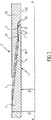
図1は、第1管11の端部に配置された雄ねじ切り部材1を備える継手を示す。この雄部材は、第2管の端部に配置されたねじ切り雌部材2と接合した状態でねじ留めされている。この場合には、雄ねじ切り部材の内径は、管11、12の内径D1と等しい。図1の実施形態では、例証の方法によってのみ、雌ねじ切り部材の外径は、管11、12の外径DEと等しい。
FIG. 1 shows a joint comprising a male thread member 1 arranged at the end of a
図1中の継手は、まだ直径拡張動作を施す以前の、接合した状態で単純にねじ留めされた状態で示されている。 The joint in FIG. 1 is shown in a joined and simply screwed state, yet before performing a diameter expansion operation.
図中の第2管12は、長い寸法の管として示されている。この第2管は、図示されていない方法で、片側に雌部材2、もう片側に第2雌部材を具備した結合部であってよく、この第2雌部材は、雌部材2に対して対称的であっても、対称的でなくてもよく、また、別の長い管の端部に配置された雄部材にねじ留めされている。
The
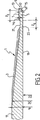
図2には、雄部材1のみを示す。 FIG. 2 shows only the male member 1.
雄部材1は雄ねじ切り部分3を備え、この雄ねじ切り部分3は、先細りし、台形のねじ切り部分を有し、溝21とリップ部5で形成された非ねじ切り端部によってその自由端部にまで延び、環状雄端面9にて終端している。
The male member 1 is provided with a male threaded
溝21は浅いU字型である。
The
これは、ねじ切り部分の直上から始まり、その深度hgは、ねじ切り部分3の高さよりも短い。そのため、溝の底部が第1ねじ切り部分の基部と接触する。
This starts immediately above the threaded portion, and its depth h g is shorter than the height of the threaded
溝Igの幅は実質的にその深度hgの4倍である。 The width of the groove I g is 4 times the substantially its depth h g.
リップ部5は、
a) 円筒形状の外縁面7と、
b) 第1管11の円筒形内縁面の端部範囲に関連した内縁面19とを備えている。
The
a) a cylindrical outer edge surface 7;
b) An
したがって、リップ部5は、管11の厚みetと実質的に等しい均一な厚みelを有する。さらに、リップ部5は、溝の端部から、実質的にリップ部の厚みelの3倍に等しい表面15の垂直部分(以下に定義する)までを測定した長さltを有する。
Accordingly, the
雄端面9は小穴を形成している。この小穴は、雄環状横断面15と、この横断面15に近接し、軸方向に突出した環状舌部13とで形成されている。雄横断面15は、小穴の、ねじ切り継手の内部に向かって方向付けされた側部上に配置されている。
The
舌部13の外縁面はリップ部の面7の延長であるため、その内縁面17は、例えば円筒形である。
Since the outer edge surface of the
舌部13の肉厚は、横断面15の厚みと実質的に同一であるため、舌部(またはその軸方向への突出部分)の高さは、舌部の肉厚と実質的に等しい。さらに、拡張中に舌部の自由端部をより確実に保持するために、該厚みを、この肉厚の1.5倍と等しくてもよい。
Since the thickness of the
図3に雌部材2のみを示す。 Only the female member 2 is shown in FIG.
雌部材2は、その自由端部から、雄ねじ切り部分3、次に非ねじ切り部分6と一致する台形のねじを具備した雌ねじ切り部分4を備えている。この非ねじ切り部分6は、雄部材1のリップ部5と一致および協働するハウジングを形成している。
The female member 2 comprises, from its free end, a female threaded portion 4 with a male threaded
雌ハウジング6は縁面8を備え、この縁面8は、内側に向かって曲がり、円筒形であり、その片側が雌ねじ切り部分4と接続し、もう片側が、雌肩部10を介して、第2管12の内部円筒形縁面20と接続している。
The female housing 6 is provided with an
概して、ハウジングの縁面8の直径は、雄リップ部5の外縁面7の直径よりも極若干だけ大きい。そのため、雄部材を雌部材にねじ込む際に、面7、8が、ほとんど隙間なく、例えば0.2mmの隙間を以って、相互内に滑入することができる。このような滑動の利点について以下に説明する。
In general, the diameter of the
雌肩部は、ほぼ一致して配置され、雄端部9の環状面と実質的に類似した形状を有する環状肩面10を備えている。面10は、雌横断環状面16と、横断面16に隣接した環状溝14とで構成された小穴を形成している。
The female shoulder includes an
雌横断面16は、ねじ切り継手の内方に方向付けた小穴の側に配置されている。
The
横断面16付近の溝14の壁18は、例えば円筒形であり、面取りまたは丸く加工した縁によって、横断面16に結合することができる。溝のこれとは反対側の壁は、縁面8の延長である。ねじ切り継手をねじ留めする際に、舌部の表面17が、舌部の自由横断端部が溝14の底部に接するまで、溝の壁18よりも上に「上昇」する。舌部14の軸高さhrと、溝の軸深度Prは、さらなるねじ留めが行われるまで横断面15、16が接触しない寸法になっている。円筒形表面7と8の間、また舌部の表面と溝の表面の間の小さな隙間はこれらの延長であるため、ねじ留めの終端部においてグリースが逃げることにより、リップ部5をハウジング6に対して正確に位置決めすることが可能となる。
The
図4〜図7は、先ほど説明したばかりの、気密拡張した継手を究極に許容するねじ切り継手により接続した管上のボールの手段によって約15%の直径拡張が実現した際に生じる変形現象を示している。 4-7 illustrate the deformation phenomenon that occurs when a diameter expansion of about 15% is achieved by means of a ball on a tube connected by a threaded joint that ultimately allows an airtight expanded joint as just described. ing.
金属材料に実施したこのような変形によって、金属の塑性変形が生じる。 Such deformation performed on the metal material causes plastic deformation of the metal.
そのため、このような塑性変形は、例えば、拡張部の上流、したがってまだ変形していない部分範囲内に位置した第2管12の139.7mm(5.5インチ)の外径から、(ボールの出口円錐部33の高さにて、またはその下流にて)拡張された第1管11の157.5mm(6.2インチ)の外径にまで達する。
Therefore, such plastic deformation is, for example, from the outer diameter of the 139.7 mm (5.5 inch) of the
発生した塑性変形により製品の降伏強度が増加し、初期の弾性限度が310MPa(45 KSI)である管では、変形後に、その弾性限度が380MPa(55 KSI)に上昇する。 The yield strength of the product increases due to the plastic deformation that has occurred, and in a tube with an initial elastic limit of 310 MPa (45 KSI), the elastic limit increases to 380 MPa (55 KSI) after deformation.
直径拡張は、適切な最大直径を有するボール30(図4)の手段によって、周知の方法で実施される。例えば、掘削ロッドの補助によって引くことにより、あるいは、水圧によって押圧することにより、このボールが管内を強制的に通過する。 Diameter expansion is performed in a known manner by means of a ball 30 (FIG. 4) having an appropriate maximum diameter. For example, the ball is forced to pass through the pipe by pulling with the aid of a drilling rod or by pressing with a hydraulic pressure.
ボールは、例えば、拡張が実施される場所である入口円錐部分31と、中間円筒形部分32と、出口円錐部分33とを備えたバイオコニカル形状を有する。ボールの各部分の全ての面は、適合された接続範囲によって結合している。
The ball has, for example, a bioconical shape with an
WO93/25800号は、炭化水素抗井の運転のための、EST(拡張可能な刻み目付き管)として周知の管の直径拡張に特別に適合された入口円錐部分の角度を特に示している。 WO 93/25800 shows in particular the angle of the inlet cone part specially adapted for the diameter expansion of the tube known as EST (expandable notched tube) for the operation of hydrocarbon wells.
管11、12の断面はほぼ均等であるため、これら管を構成している金属の変形量が十分である場合、ボール通過中に管の端部に特に問題が生じることはない。
Since the cross-sections of the
ねじ切り継手の拡張工程は、図4〜図7に示した4段階に分割することができる。 The expansion process of the threaded joint can be divided into four stages shown in FIGS.
拡張動作全体を逆方向において実施することもでき、さらに、これによって適当な結果を得ることも可能であるが、ここでは、ボールが第1管11の雄部材1から第2管12の雌部材2へと移動する好ましい変形モードを示した。
a) ボール円錐部分上での拡張段階
図4は、この段階におけるねじ切り継手を示す。
The entire expansion operation can also be carried out in the opposite direction, and it is possible to obtain suitable results, but here the ball is moved from the male member 1 of the
a) Expansion stage on the ball cone part FIG. 4 shows the threaded joint at this stage.
この拡張は、ボール30の入口円錐部分31によって実施され、図4は、直径拡張の際における雄3と雌ねじ切り部分4を示す。
This expansion is performed by the entrance
図4中では、ボール30の入口円錐部分31が、雄リップ部およびこれと一致する雌ハウジング範囲を、接続軸に対して傾斜させるべく屈曲させることにより、これらの変形を開始する。
In FIG. 4, the
この拡張段階の際に、ボール30の通過への反動負荷が、第1管11から第2管12へ段階的に伝達される。
During this expansion stage, the reaction load for passing the
これらの反動負荷のために、この拡張段階中に、雄リップ部5が、雌肩部10の環状力によって軸方向に圧縮される。
Due to these reaction loads, the
この拡張段階の最後では、雄部材の自由端部がボールの入口円錐部分31の端部に到着する。
b) 屈曲段階
この段階中には、雄リップ部が、ボールの中心部分32と同じ高さに配置される。図5を参照のこと。
i) 雄リップ部
雄リップ部5の両端部が、逆方向への曲げモーメントに晒される。
At the end of this expansion phase, the free end of the male member arrives at the end of the
b) Bending phase During this phase, the male lip is located at the same height as the
i) two end portions of the male lip
実際には、支持面15、16を備えた小穴と、舌部13/溝14の埋め込み型装置とによって、雄端面9が雌肩部面10内の適所に維持される。
In practice, the
小穴の埋め込みにより、雄リップ部5の自由端部範囲が、肩部を超える雌部材の全厚み範囲22の傾斜を強制的に追従する。この範囲22は、ボールの入口円錐部分31上で再び拡張工程に課され、これにより、この高さにおいて曲げモーメントが生じる。
By embedding the small holes, the free end portion range of the
雄ねじ切り部分3の側にあたる、リップ部の他端はもはや支持されておらず、また、これとは反対に、リップ部を、その自由端部におけるものとは逆の曲げモーメントに課する。
The other end of the lip, which is on the side of the male threaded
雄リップ部の2つの端部における対極する曲げモーメントにより、雄リップ部5が図5に示すようにバナナ形状に湾曲し、その一方で、リップ部5の外縁面7が、湾曲した凸型形状を呈する。
Due to the opposing bending moments at the two ends of the male lip portion, the
拡張段階の最後における、雄リップ部5の軸方向への圧縮の状態によって、その湾曲が、曲げモーメントの影響下で促進される。
Due to the axial compression state of the
雄リップ部5と雄ねじ切り部分3の間に配置された溝21が、この湾曲を実施できる幅を制限することで、雄リップ部の湾曲を強調する塑性旋回部分として機能する。
The
しかしながら、この場合には、雄リップ部上への軸方向への圧縮応力は、溝の下での金属23の曲げは発生しない。この座屈が、溝の下における、内縁面19に対する金属の突出に変換される。
ii) 雌ハウジング
同一の曲げ現象が雌ハウジング上で生じる。
However, in this case, the compressive stress in the axial direction on the male lip portion does not cause bending of the
ii) The same bending phenomenon on the female housing occurs on the female housing.
全厚みの範囲22は、中央部分の通過後に、さらなる拡張を経験するリップ部の比較的薄い範囲と比べて比較的硬質であるため、範囲22の内径が、ボールの中央範囲32の内径よりも大きくなることが可能である。さらなる拡張現象については、明細書WO93/25800号に記載されている。
c) 補強段階
図6に示したこの段階は、ボール30の中央部分32にかけての全厚みの雌範囲22の通路に関連している。
i) 雌ハウジング
先行の段階で生じた屈曲は、引張応力と円周応力の影響下でゼロに戻ってしまう傾向にあり、これにより、湾曲に対する軸方向への屈曲応力の状態が生じるため、補強が実現する。
Since the
c) Reinforcement stage This stage, shown in FIG. 6, relates to the passage of the full thickness
i) Bending that occurred in the stage prior to the female housing tends to return to zero under the influence of tensile stress and circumferential stress, which results in a state of bending stress in the axial direction against bending, thus reinforcing Is realized.
これらの応力によって生じた曲げモーメントは、補強部分の上流にあたる材料の厚みに比例する。曲げモーメントは、全厚み(範囲22)の管12に到達する時点では、雌ハウジングの内縁範囲を強化するには十分でなくなっているため、製品の軸方向へと降下する傾向にある。この行動は、管12の外径の局所的な縮小によって現れる。
ii) 雄リップ部
雌部分の補強の際に、屈曲によって生じた軸方向への屈曲における差が減少する。そのため、雄リップ部5が、圧縮下にある状態を徐々に損失してゆく。その後、初期段階では接合状態にある表面15、16が分離する。この減少は、接合部分15、16の開放の効果を生じる雌ハウジングの内縁面8の「ダイバー」によって強化される。
The bending moment produced by these stresses is proportional to the thickness of the material that is upstream of the reinforcing portion. When the bending moment reaches the
During reinforcement ii) male lip female part, the difference in the bending in the axial direction caused by bending is decreased. Therefore, the
先行の段階で強制されたバナナ形状の変形が維持される。
d)最終段階
図7は、ボールが通過した後の、ねじ切り継手の最終段階を示す。
The banana-shaped deformation forced in the previous stage is maintained.
d) Final Stage FIG. 7 shows the final stage of the threaded joint after the ball has passed.
拡張によって生じたフープ応力の状態によって、雄リップ部の外縁面7上で雌ハウジングの内面8が収縮する。これにより、気密性が保証される、拡張した状態にあるねじ切り継手の表面7、8の自己収縮を参照することができる。小穴9、10の埋め込みによって引き起こされた半径方向への逸脱が十分な塑性変形を生じたため、雄リップ部5が軸に向かって降下することがない。
Due to the state of the hoop stress caused by the expansion, the
ボール通過後の、ねじ切り継手の部材のスプリングバックは、実現された塑性変形と比較すれば無視できる程度のものである。 The springback of the threaded joint member after passing the ball is negligible compared to the plastic deformation realized.
半径方向への焼きばめは、ねじ切り継手における内圧または外圧にて確実な気密性を得るのに十分な、数十MPa、さらには100MPaよりも高い接触圧力を誘発する。焼きばめは、接触面の全円周にかけて十分な長さを有するため、これらの接触面間に安定した気密性が確実に得られる。 Radial shrink fitting induces contact pressures higher than a few tens of MPa, and even 100 MPa, sufficient to obtain reliable hermeticity at internal or external pressure at the threaded joint. The shrink fit has a sufficient length over the entire circumference of the contact surfaces, so that stable airtightness can be reliably obtained between these contact surfaces.
ボール30を10〜30MPaの圧力下において水圧で押圧することにより拡張を実施する場合には、さらなる気密性が必要となり、また、既に拡張された継手に何らかの漏出があった場合、ボールの、ストリング内のさらなる前進貫通が妨げられ、その結果、拡張の工程が妨害されてしまう。
When expansion is performed by pressing the
拡張を行う以前に、ねじ切り継手の雄リップ部5の縁面7と雌ハウジングの縁面8の間に隙間が空き過ぎていると、拡張作業の最後にこれらの表面の焼きばめが不可能になってしまう。
If there is too much clearance between the edge surface 7 of the
拡張以前の初期状態におけるこれら縁面の間の半径方向の干渉は、拡張動作の最後にこれらの面の焼きばめの実施を可能にする、該面間の差分変形(湾曲、直線化)を妨害してしまう。さらに、これにより、これらの面を相互に対しねじ留めする際に、これらの面が摩損したり、また、面9、10の不正確な埋め込みにより、部材の配置が適切に行われない可能性も生じ、その結果、拡張後の面7、8の焼きばめが上手くいかないことがある。
The radial interference between these edge surfaces in the initial state prior to expansion causes differential deformation (curvature, linearization) between the surfaces, which makes it possible to perform a shrink fit of these surfaces at the end of the expansion operation. It will interfere. In addition, this may cause these surfaces to wear when they are screwed to each other, and improper embedding of the
一の好ましい実施形態では、横断面15、16、舌部13/溝14機構を有する環状小穴を備えた形態により、拡張中における雄自由端部の降下を防止することが可能になる。同様の結果を得るために、包囲された面9、10の別の実施形態も可能である。
In one preferred embodiment, the configuration with an annular
管11、12の厚さetの1/3よりも薄い厚さelの雄リップ部5が小さすぎると、横断面15、16との有効な接合が実現しない。
When the male lip of reduced thickness e l than 1/3 of the
一方、雄リップ部5の厚さelが、管11、12の厚さetの2/3よりも厚い場合には、雌ハウジングの高さにおける管12の厚さによって、弱過ぎるために、ねじ切り部分の引張に対して十分な抵抗を提供できない雌ねじ切り部分4の微小断面が生じてしまう。
On the other hand, the thickness e l of the
雄リップ部5の長さ/厚さの比率は、リップ部5の圧縮および屈曲下での行動を表す。
The length / thickness ratio of the
その厚さよりも短い長さllの雄リップ部5では、雄リップ部5の縁面7の屈曲、および/または、雌ハウジングの縁面8の直線化を十分に得ることができない。
In the
その厚さelの4倍よりも長い長さllを有する雄リップ部5によって、雄リップ部の曲げと、ねじ切り部分側における内方への突起が生じる。
The
この効果は、雄ねじ切り部分3と雄リップ部5の間の溝21の存在によって強調される。
This effect is emphasized by the presence of the
これが、溝がねじ切り部分の高さに制限された深度と、その深度に対して制限された長さを有することが好ましい理由である。 This is why it is preferable for the groove to have a depth limited to the height of the threaded portion and a length limited to that depth.
不十分な肉厚と、この肉厚よりも低い軸高さを有する舌部13は、拡張の際に、十分に支持されることができない。
A
次に図8を参照すると、部分的にねじ切りした管状部材同士をねじ留めした後の管状継手を示しており、この継手は、本発明に従って、直径方向に拡張される。 Referring now to FIG. 8, the tubular joint is shown after the partially threaded tubular members are screwed together, and the joint is expanded diametrically in accordance with the present invention.
この継手は、図1に示した雄管状部材11と雌管状部材12を備えている。雄管の端部にはリップ部5が設けられており、このリップ部5の縁面8は、継手を拡張すると、雌管12の雌ハウジング8の縁面7と接触することが可能になる。拡張後の、表面7、8の間に接触溶融を有する接触範囲は、継手内部に向かって配置されているため、内部密封範囲Clとして知られている。拡張後に、雄リップ部の舌部の表面と、その反対側にあたる、雌管状部材の溝の表面との間にも接触範囲ができる。
This joint includes the
管状スリーブ36が、雌管状部材12と同心的に配置されている。この管状スリーブ36は、管状部材11、12をねじ留めする前に、操作者がこの管状スリーブを雌管状部材12にねじ留めし、管状部材12の外面37と接触させることを許容するだけの内径を備えている。この管状スリーブは、リップ部5と軸方向に重なり、リップ部5を超えていずれかの方向、つまりねじ切り部分の側へ、舌部13を超えて延びるために、その長さlm1の全長にかけて延びている。管状スリーブ36は、リップ部上に有利に中心決めされている。
A
ねじ留めの最後、および拡張の前に、舌部13が、溝14の底部に対して軸方向に接合され、また、密封面7、8は円筒形であり、ねじ留め時に、相互との間に若干の隙間を設けて配置されている。拡張の際に、リップ部5は舌部13の埋め込み装置、溝14によって保持される。
At the end of screwing and before expansion, the
実施例において、管状スリーブ36は、例えば管状部材の材料のものと同一の降伏強度を有する管状部材の材料と同じ材料で構成されている。直径に沿った拡張後に、管状スリーブが弾性スプリングバック力を発生し、これが雌部材の弾性スプリングバック力に加えられ、雌部材のスプリングバック力を相殺する。雌部材に重ねた管状スリーブの焼きばめがこのように実施される。さらに、一方で雄部材と、他方でスリーブと雌部材から成る組み立て品とのスプリングバック力の差によって、雌部材の圧縮が生じる。管状スリーブ36が表面7、8と重なり、若干該表面を越えると、圧縮が伝搬されて、雄部材の密封面7と雌部材の密封面8間の接触圧力が増加する。雄部材に重ねた雌部材の焼きばめが、このようにして実施される。管状スリーブ36を設けるためには、管状スリーブが存在しない場合よりもかろうじて高く(約10%)、また、拡張後に内部密封範囲Clにおいて接触圧力を大幅に補強する(厚さ4〜5mmのスリーブについて約200%)拡張エネルギーが必要である。
In the embodiment, the
上述した実施形態において、拡張前の管状スリーブ36は以下により定義される。すなわち、
‐ 少なくともリップ部1の長さとほぼ等しい重なり部分の長さlm1に、ねじ切り部分の回転幅の約2〜最大約8倍の長さを加えたものと、
‐ 継手の最大屈曲によって指定される最大肉厚と、ねじ切りした部材のスプリングバック力へのスリーブの弱すぎる効果によって指定される最大肉厚との間で制限された肉厚em1とであり、この肉厚は、外径150mm、厚さ7〜8mmの管では、約数ミリメートル、例えば最低1.5mm、好ましくは4〜5mmである。好ましいスリーブの厚さは、実質的に雄リップ部の厚さに近い。拡張後の肉厚は最低で1mmと等しい。
In the embodiment described above, the
-At least the overlapping part length lm1 approximately equal to the length of the lip part 1 plus a length of about 2 to up to about 8 times the rotational width of the threaded part;
-A wall thickness em1 limited between the maximum wall thickness specified by the maximum bending of the joint and the maximum wall thickness specified by the too weak effect of the sleeve on the springback force of the threaded member, and this The wall thickness is about a few millimeters, for example a minimum of 1.5 mm, preferably 4-5 mm, for tubes with an outer diameter of 150 mm and a thickness of 7-8 mm. The preferred sleeve thickness is substantially close to the thickness of the male lip. The wall thickness after expansion is at least equal to 1 mm.
本発明の一の実施形態では、表面7、8が、直径方向への拡張後に、継手の内部密封範囲Clとして周知の範囲を画定する。しかし、図8に示した気密継手の拡張の前後に、別の密封範囲が形成される。
In one embodiment of the invention, the
そのため、雌管状部材12は、そのねじ切り部分とその自由端部の間に、非ねじ切り雌リップ部38を備えている。この雌リップ部38は、環状面を形成する半径方向面39にて終端している内縁面41を備える。雄管状部材11は、自由端部とは反対側の、雄ねじ切り部分の外縁面40を備えている。雄管状部材と雌管状部材を相互に対して完全にねじ留めすると、内縁面41が、雄管状部材11の外縁面40と経方向に干渉し合い、拡張前に気密範囲を画定する。表面40、41の両方は円錐形であり、類似の円錐度を有する。拡張の際に、雌リップ部雄部材に対して軸方向に接合しておらず、雌部材に対して軸方向に接合している雄リップ部の場合に見られるような、曲げまたは曲げ抵抗の徴候はない。したがって、雌リップ部は軸に向かって降下しない。拡張後に、リップ部38に、直下にある雄部材のものよりも若干大きなスプリングバック変位のみが生じる。これにより、雌リップ部の内縁面41と、対応する雄管状部材11の縁面40との間に気密接触が生じる。相互に対するねじ留め後の表面40、41の干渉によって、拡張の最後にスプリングバックが生じた際に、これらの表面間の確実な接触が得られる。
Therefore, the
拡張後の表面40、41の間の気密接触範囲は、継手の外側に向かって配置されているために、外部気密範囲CEとして知られている。 The hermetic contact range between the expanded surfaces 40, 41 is known as the outer hermetic range CE because it is arranged towards the outside of the joint.
しかし、これ以外の手段とは別に、範囲CEに作成された外部気密性は、範囲CIに作成された外部気密性よりも低い。 However, apart from the other means, the external airtightness created in the range CE is lower than the external airtightness created in the range CI.
管状スリーブ34は、雌管状部材12と同心的に配置されている。この管状スリーブ34は、管状部材11、12を雌管状部材12上にねじ留めして、管状部材12の外面37と接触させる前に、操作者が管状スリーブをねじ切りすることを許容するだけの内径を備えている。この第2管状スリーブは、拡張の前後に気密範囲の画定を可能にする縁面40、41の上に軸方向に重なるように、また、いずれかの側において、これらの表面を超えて延びる、つまり、ねじ切り部分側で、半径方向面39を超えて延びることができるようにするために、 その全長lm2にかけて延びている。この例証では、管状スリーブ34は、管状部材材料と類似した材料から成り、その降伏強度は、例えばこれらの管状部材の材料の降伏強度と等しい。直径方向への拡張の後に、管状スリーブがスプリングバック力を生じるが、雄部材の弾性復元力を相殺するために、これが雌部材のスプリングバック力に追加される。雌部材上への管状スリーブの焼きばめがこのようにして実施される。さらに、スリーブと雄部材の内面との間のスプリングバックの差によって、雌部材の圧縮が生じる。管状スリーブ34が表面40、41と重なり、これを若干超えるため、圧縮が、雄部材と雌部材の密封面40、41と、スリーブ34を備えていない類似の継手との間の接触圧力の増加に変換される。さらに、雄部材上への雌部材の焼きばめも実施される。管状スリーブ34を設けるには、管状スリーブを備えていないものよりもかろうじて大きな拡張エネルギーが必要であり、この管状スリーブ34によって、拡張後に、外方密封範囲CEおける接触圧力が大幅に増加する(約300%以上)。
The
記述した実施形態では、拡張前に、管状スリーブ34が以下によって規定される。すなわち、
‐ 雌リップ部38の軸方向への長さとほぼ等しい重なる長さlm2に、ねじ切り部分の幅の約2〜最大8倍の長さと、
‐ 継手の最大屈曲により指定された最大厚さと、スプリングバックへの弱すぎる効果によって指定された最大厚さとの間で制限された厚さem2とであり:この厚さem2は、外径訳150mm、厚さ7〜8mmの管で、約数ミリメートル、例えば少なくとも1.5mm、好ましくは4〜5mmであれば有利である。さらにここでも、スリーブ34の厚さは、雌リップ部のものとほぼ同サイズであることが好ましい。拡張後に、半径に沿った厚さは少なくとも1mmと等しくなる。
In the described embodiment, prior to expansion, the
-An overlapping length lm2 substantially equal to the axial length of the female lip 38, and a length of about 2 to 8 times the width of the threaded portion;
-A thickness em2 limited between the maximum thickness specified by the maximum bending of the joint and the maximum thickness specified by the too weak effect on the springback: this thickness em2 is an outer diameter of 150 mm It is advantageous if the tube is 7-8 mm thick and is about a few millimeters, for example at least 1.5 mm, preferably 4-5 mm. Also here, the thickness of the
スリーブ34またはスリーブ36のいずれについても、雄ねじ切り部材と雌ねじ切り部材から連続していない短いスリーブは、長く追加したスリーブ、または1つまたは複数のスリーブではなく雌部材の材料に単純に追加した厚さよりも、特に外部気密性の気密性能を大幅に改善することがわかっている。このような示唆は絶対的に明らかであるとは言えない。
For either
様々なスリーブの取り付け方法が考えられる。 Various methods of attaching the sleeve are conceivable.
一の実施形態では、管状スリーブ34の1端には経方向の突起部42が設けられている。そのため、管状部材11と12を相互に対してねじ留めする前に、操作者は、管状スリーブ34を、突起部を有する側とは反対側の端部から、管状部材12上にねじ切りするが、この場合、スリーブの内縁面は外縁面37と接触している。管状スリーブ34は、経方向の突起部42が半径方向面39と接触するまで、ねじ切りされる。このようにして、管状スリーブ34が軸方向に位置決めされる。経方向の突起部42は、接触圧力を改善するよう、半径方向面39に有利に接着されている。酸素欠如状態において数分間で硬化し、拡張中において雌部材に対する管状スリーブの位置を保持することが可能な「グリース接着剤」を使用することができる。拡張中に、接着剤の層を、危険を冒すことなくせん断、破壊することが可能である。
In one embodiment, a
一の変形実施形態では、管状スリーブ36または/そして34(単数または複数)を、相互に対してねじ留めする前に管状部材12上にねじ切りし、次に、雌管状部材12の外縁面37上にマーキングする手段によって、軸方向に向かって位置決めされる。この場合、マーキングは浅い溝であってよい。管状スリーブ(単数または複数)36および/または34の軸方向への位置決めは、経方向突起部を備えたスリーブの場合と同様に、「グリース接着剤」の手段によって保持することができる。管状スリーブ(単数または複数)36および/または34の軸方向への位置決めは、雌管状部材上に極若干だけ焼きばめすることで実施できる。焼きばめは、スリーブの加熱および/または雌部材の冷却によって実施できる。
In one alternative embodiment, the
管状スリーブの肉厚を、スリーブによって為された気密性の強化における効率を低下することによって低減することができる。しかし、薄型のスリーブでは、雄部材11および雌部材12の降伏強度に対するその降伏強度を増加させることで、その効率性の損失をいくらか補正することが可能である。スリーブの降伏強度が雄部材および雌部材降伏強度と比較してより高いほど、所与の厚さにおける気密性が向上する。管状スリーブの降伏強度は熱処理によって変更が可能である。しかし、材料に関する問題の大部分は、降伏強度を増加することで縮小する。管状スリーブを破損することなく、直径方向への拡張を生じるのに十分でなければならない問題と、管状スリーブの制限された肉厚に関係なく十分な気密特性を確実に得るための十分に高い降伏強度との間には妥協が見られる。
The wall thickness of the tubular sleeve can be reduced by reducing the efficiency in enhancing the tightness made by the sleeve. However, with a thin sleeve, it is possible to compensate for some loss in efficiency by increasing its yield strength relative to the yield strength of
管状部材は、1つの外部気密範囲CEまたは内部気密範囲CIしか備えていない場合、この気密範囲によって、内側から外側、さらに外側から内側へ流れる流体に対する気密性を確実に得ることが可能である。この場合、「外部気密範囲」と「内部気密範囲」という用語は、気密範囲を、実質的に、雄管状部材または雌管状部材の自由端部に配置することが可能であることを意味する。 When the tubular member has only one outer hermetic range CE or inner hermetic range CI, this hermetic range can ensure airtightness with respect to fluid flowing from the inside to the outside and further from the outside to the inside. In this case, the terms “external hermetic range” and “inner hermetic range” mean that the hermetic range can be arranged substantially at the free end of the male or female tubular member.
付録Iでは、ねじ切り継手の相対性質を、接触部の幅にかかる統合的な接触圧力として示している。この研究は、単純な基準のねじ切り継手(ケース1)に対して、この単純なねじ切り継手に適合した本発明の様々な実施形態を比較させることを目的としている。基準として採用した継手は、551MPaの最低降伏強度に関連した等級APIL80(API=米国石油協会)用に処理された米国基準(欧州基準X20Cr13に対応する)に準拠したAlSl420(13% Cr)の鋼鉄製の、外径152.4mm(6インチ)、計量重量27.8kg/m(18.6lb/ft)のねじ切り継手である。 Appendix I shows the relative nature of the threaded joint as an integral contact pressure over the width of the contact. This study is aimed at comparing various embodiments of the present invention adapted to this simple threaded joint against a simple reference threaded joint (case 1). The joint adopted as the standard is an AlSl420 (13% Cr) steel according to the US standard (corresponding to the European standard X20Cr13) processed for the grade APIL80 (API = American Petroleum Institute) associated with a minimum yield strength of 551 MPa. This is a threaded joint with an outer diameter of 152.4 mm (6 inches) and a weight of 27.8 kg / m (18.6 lb / ft).
表1、2は、考慮した以下の基準ケースの内部気密性と比較した各ケースの比率としての外部気密性および内部気密性の結果にそれぞれ関連している。 Tables 1 and 2 relate to the results of external airtightness and internal airtightness as a percentage of each case compared to the internal airtightness of the following reference cases considered, respectively.

‐ ケース2: 雄ねじ切り部材固定され、ねじ切り部分、雄・雌リップ部と重なった、厚さ4.5mmで、ねじ切り継手のもの(13%Cr)と同一の鋼鉄から成り、該継手(APIL80)と同様に処理された、非常に長いスリーブで被覆した基準のねじ切り継手、
‐ ケース3: 先行のケースと同じ厚さ、材料を有し、同じ処理を施した本発明による2つの短いスリーブ(図8)を備えた基準のねじ切り継手である。
-Case 2: Male threaded member fixed, overlapped with threaded part, male / female lip part, 4.5mm thick, made of the same steel as that of threaded joint (13% Cr), this joint (APIL80) Standard threaded joint, covered with a very long sleeve, treated in the same way as
Case 3: A standard threaded joint with two short sleeves (FIG. 8) according to the invention having the same thickness, material and the same treatment as the previous case.
‐ ケース4: ケース3と同様であるが、雌リップ部の高さに配置された1つのスリーブを備え、非常に薄く(厚さ1.6mm)、雌部材の経方向突起部の高さに接着されている点が異なる。
-Case 4: Same as
‐ ケース5: ケース4と同様であるが、(弾性限度Rp0.2≧758MPaに関連した)等級APIP110として処理した1つのスリーブを備えている点が異なる。 -Case 5: Same as Case 4, except that it has one sleeve treated as grade APIP110 (related to the elastic limit R p0.2 ≧ 758 MPa).
ケース1では、内部気密性が非常に優れているが、外部気密性は低い(内部気密性の44%)。長いスリーブ(ケース2)だけが、内部気密性を向上する。ケース2と類似の厚さを有する2つの短いスリーブ(ケース3)を使用することで、外部気密性と内部気密性の両方を向上することが可能である。厚さ(ケース4)を劇的に低減することで、十分な外部気密性を保持することができる(しかし、研究例は1つしかない)。スリーブの等級を上げ、降伏強度を上昇させることで(ケース5)、外部気密性の増加し、基準のケースの気密性レベルに実質的に達することが可能である。 In Case 1, the internal airtightness is very good, but the external airtightness is low (44% of the internal airtightness). Only the long sleeve (case 2) improves the internal tightness. By using two short sleeves (case 3) having a thickness similar to that of case 2, it is possible to improve both external airtightness and internal airtightness. By dramatically reducing the thickness (case 4), sufficient external airtightness can be maintained (but there is only one study example). By raising the sleeve grade and increasing the yield strength (case 5), it is possible to increase the external tightness and substantially reach the tightness level of the reference case.
直径方向の拡張のために、スリーブの存在によって生じた作動力のピーク(ここには示していない)と、拡張エネルギーは非常に限られている。 Due to the diametrical expansion, the peak of actuation force (not shown here) caused by the presence of the sleeve and the expansion energy are very limited.
2つの内部気密範囲と外部気密範囲を備えた管状部材について、管状スリーブの変形実施形態は、管状締め金46で相互に接続された図8のスリーブ34、36を備えた、図11に示した管状重なり部品45から成る。この管状締め金46の肉厚は、締め金46の全長にかけての半径方向拡張力と実質的に対抗しないように、スリーブ34、36の肉厚よりも遥かに薄い。
For a tubular member with two internal and external tight areas, an alternative embodiment of the tubular sleeve is shown in FIG. 11 with the
この重ね部品の様々な組み立て方法は、管状スリーブ34を単独で使用する場合のものと同一である。
The various methods for assembling the overlapping parts are the same as when the
本発明は、例証の方法で記述した実施形態に限定されるものではない。 The invention is not limited to the embodiments described by way of example.
本発明は、内部気密範囲のみを備えた継手、または外部気密範囲のみを備えた継手、または両方の気密範囲を備えた継手のいずれにも適用する。本発明は、これ以外の、例えば中間気密範囲といった気密範囲を備える継手にも適用可能である。 The present invention applies to any of joints having only an internal hermetic range, joints having only an external hermetic range, or joints having both hermetic ranges. The present invention can be applied to other joints having an airtight range such as an intermediate airtight range.
1 雄のねじ切り部材
2 雌のねじ切り部材
3 雄ねじ切り部分
4 雌ねじ切り部分
5 リップ部
6 ねじ切りされていない部分
7 外縁面
8 縁面
9 管状雄端面
10 雌肩部
11 第1管
12 第2管
13 環状舌部
14 管状溝
15 表面
16 雌横断管状面
17 舌部の表面
18 壁
19 内縁面
20 内部円筒形縁面
21 溝
22 範囲
23 金属
24 溝の底部
30 ボール
31 入口円錐部
32 中間円筒形部分
33 出口円錐部
34 スリーブ
36 管状スリーブ
37 外面
38 ねじ切りされていない雌リップ部
39 半径方向面
40 外縁面
41 内縁面
42 経方向突起部
CE 外部気密範囲
Cl 内部密封範囲
DE 外径
DI 内径
el リップ部の厚さ
em1 肉厚
em2 厚さ
et 管の厚さ
hg ねじの深度
It 管の長さ
Im1 重なり長
DESCRIPTION OF SYMBOLS 1 Male threaded member 2 Female threaded
Claims (20)
Applications Claiming Priority (2)
| Application Number | Priority Date | Filing Date | Title |
|---|---|---|---|
| FR0208080A FR2841626B1 (en) | 2002-06-28 | 2002-06-28 | REINFORCED TUBULAR THREADED JOINT FOR IMPROVED SEALING AFTER PLASTIC EXPANSION |
| PCT/FR2003/001744 WO2004003416A1 (en) | 2002-06-28 | 2003-06-11 | Reinforced tubular threaded joint for improved sealing after plastic expansion |
Publications (2)
| Publication Number | Publication Date |
|---|---|
| JP2005536691A JP2005536691A (en) | 2005-12-02 |
| JP4234100B2 true JP4234100B2 (en) | 2009-03-04 |
Family
ID=29724970
Family Applications (1)
| Application Number | Title | Priority Date | Filing Date |
|---|---|---|---|
| JP2004516838A Expired - Fee Related JP4234100B2 (en) | 2002-06-28 | 2003-06-11 | Reinforced tubular joints for improving hermeticity after plastic expansion |
Country Status (20)
| Country | Link |
|---|---|
| US (1) | US7581766B2 (en) |
| EP (1) | EP1518068B1 (en) |
| JP (1) | JP4234100B2 (en) |
| CN (1) | CN100482998C (en) |
| AR (1) | AR040307A1 (en) |
| AT (1) | ATE360778T1 (en) |
| AU (1) | AU2003255659B2 (en) |
| BR (1) | BR0312117B1 (en) |
| CA (1) | CA2489516C (en) |
| DE (1) | DE60313460T2 (en) |
| EA (1) | EA006214B1 (en) |
| EG (1) | EG23594A (en) |
| FR (1) | FR2841626B1 (en) |
| MX (1) | MXPA05000026A (en) |
| MY (1) | MY137063A (en) |
| NO (1) | NO20050243L (en) |
| OA (1) | OA12828A (en) |
| PL (1) | PL207609B1 (en) |
| UA (1) | UA79618C2 (en) |
| WO (1) | WO2004003416A1 (en) |
Families Citing this family (49)
| Publication number | Priority date | Publication date | Assignee | Title |
|---|---|---|---|---|
| US7357188B1 (en) | 1998-12-07 | 2008-04-15 | Shell Oil Company | Mono-diameter wellbore casing |
| US7793721B2 (en) | 2003-03-11 | 2010-09-14 | Eventure Global Technology, Llc | Apparatus for radially expanding and plastically deforming a tubular member |
| US7546881B2 (en) | 2001-09-07 | 2009-06-16 | Enventure Global Technology, Llc | Apparatus for radially expanding and plastically deforming a tubular member |
| FR2844331B1 (en) * | 2002-01-03 | 2004-11-26 | Vallourec Mannesmann Oil & Gas | PROCESS FOR PRODUCING A SEALED TUBULAR JOINT WITH PLASTIC EXPANSION |
| EP1985797B1 (en) | 2002-04-12 | 2011-10-26 | Enventure Global Technology | Protective sleeve for threated connections for expandable liner hanger |
| CA2482278A1 (en) | 2002-04-15 | 2003-10-30 | Enventure Global Technology | Protective sleeve for threaded connections for expandable liner hanger |
| AU2003265452A1 (en) | 2002-09-20 | 2004-04-08 | Enventure Global Technology | Pipe formability evaluation for expandable tubulars |
| WO2004074622A2 (en) * | 2003-02-18 | 2004-09-02 | Enventure Global Technology | Protective compression and tension sleeves for threaded connections for radially expandable tubular members |
| US7886831B2 (en) | 2003-01-22 | 2011-02-15 | Enventure Global Technology, L.L.C. | Apparatus for radially expanding and plastically deforming a tubular member |
| US20080136181A1 (en) * | 2003-02-18 | 2008-06-12 | Enventure Global Technology | Protective Compression and Tension Sleeves for Threaded Connections for Radially Expandable Tubular Members |
| GB2415988B (en) | 2003-04-17 | 2007-10-17 | Enventure Global Technology | Apparatus for radially expanding and plastically deforming a tubular member |
| GB0313472D0 (en) * | 2003-06-11 | 2003-07-16 | Weatherford Lamb | Tubing connector |
| GB0317395D0 (en) * | 2003-07-25 | 2003-08-27 | Weatherford Lamb | Sealing expandable tubing |
| GB0317547D0 (en) * | 2003-07-26 | 2003-08-27 | Weatherford Lamb | Sealing tubing |
| US7712522B2 (en) | 2003-09-05 | 2010-05-11 | Enventure Global Technology, Llc | Expansion cone and system |
| FR2863033B1 (en) * | 2003-11-28 | 2007-05-11 | Vallourec Mannesmann Oil & Gas | REALIZATION, BY PLASTIC EXPANSION, OF A SEALED TUBULAR JOINT WITH INCLINED STRAINING SURFACE (S) |
| FR2863029B1 (en) * | 2003-11-28 | 2006-07-07 | Vallourec Mannesmann Oil & Gas | REALIZATION, BY PLASTIC EXPANSION, OF A SEALED TUBULAR JOINT WITH INITIAL LOCAL SENSITIZER (S) (S) |
| CA2563736C (en) * | 2004-04-21 | 2012-11-27 | Grant Prideco, L.P. | Method and apparatus for sealing radially expanded joints |
| US7585002B2 (en) * | 2004-04-21 | 2009-09-08 | Baker Hughes Incorporated | Expandable tubular connection |
| US7819185B2 (en) | 2004-08-13 | 2010-10-26 | Enventure Global Technology, Llc | Expandable tubular |
| FR2874988B1 (en) | 2004-09-09 | 2008-05-02 | Vallourec Mannesmann Oil & Gas | MALE ELEMENT FOR A TUBULAR THREADED SEAL AFTER DIAMETER EXPANSION |
| US7798536B2 (en) * | 2005-08-11 | 2010-09-21 | Weatherford/Lamb, Inc. | Reverse sliding seal for expandable tubular connections |
| US20070035132A1 (en) * | 2005-08-11 | 2007-02-15 | Grinaldi Ltd | Expandable tubular connection |
| US20070035131A1 (en) * | 2005-08-11 | 2007-02-15 | Grinaldi Ltd | Expandable tubular connection |
| US20070035127A1 (en) * | 2005-08-12 | 2007-02-15 | Benzie Scott A | Protective sleeve for tubular connection |
| US7549682B2 (en) * | 2005-09-19 | 2009-06-23 | Vetco Gray Inc. | Threaded pipe connector |
| US20090302604A1 (en) * | 2005-10-11 | 2009-12-10 | Enventure Global Technology, L.L.C. | Method and Apparatus for coupling Expandable Tubular Members |
| FR2895485B1 (en) | 2005-12-23 | 2012-04-13 | Vallourec Mannesmann Oil & Gas | EXTERNAL PROTECTION OF TUBULAR THREADED JOINTS FOR EXPANDING |
| WO2008047378A2 (en) * | 2006-01-30 | 2008-04-24 | Tema India Limited | A process of fitting a shrink ring |
| US20100225107A1 (en) * | 2006-02-17 | 2010-09-09 | Norsk Hydro Asa | Gas Tight Tubular Joint or Connection |
| EP2267268A3 (en) * | 2006-05-22 | 2016-03-23 | Weatherford Technology Holdings, LLC | Apparatus and methods to protect connections |
| GB0610987D0 (en) * | 2006-06-03 | 2006-07-12 | Elmar Services Ltd | Method and Apparatus |
| FR2904031B1 (en) * | 2006-07-20 | 2014-03-07 | Vallourec Mannesmann Oil & Gas | MALE ELEMENT FOR A DRILLING COMPONENT WITH EXTERNAL STOP AND INTERNAL STOP ADAPTED TO THE LENGTH WITHOUT LOSS OF RESISTANCE TORQUE, AND ASSOCIATED DRILLING COMPONENT ASSEMBLY. |
| WO2008097224A1 (en) * | 2007-02-08 | 2008-08-14 | Mohawk Energy Ltd. | Protective sleeve for tubular connection |
| FR2912730B1 (en) | 2007-02-21 | 2012-07-06 | Vallourec Mannesmann Oil & Gas France | DEVICE FOR PROTECTING A FEMALE END OF A TUBULAR JOINT COMPONENT WITH ANTI-CUT-OFF BRAKE. |
| FR2954453B1 (en) | 2009-12-23 | 2012-03-09 | Vallourec Mannesmann Oil & Gas | ASSEMBLY FOR CARRYING OUT A THREADED SEAL, METHOD FOR SCREWING AND DISCRIMINATING SUCH A SEAL AND USE OF SUCH JOINT IN AN UNDERWATER UPLINK |
| FR2956466B1 (en) | 2010-02-17 | 2012-06-08 | Vallourec Mannesmann Oil & Gas | EXPANDABLE THREAD JOINT AND METHOD OF MAKING SAME |
| JP5665653B2 (en) * | 2011-05-23 | 2015-02-04 | エヌケーケーシームレス鋼管株式会社 | Double shoulder type tool joint |
| FR2984395B1 (en) * | 2011-12-19 | 2013-12-27 | Vallourec Mannesmann Oil & Gas | TUBULAR COMPONENT FOR DRILLING AND OPERATING HYDROCARBON WELLS AND RESULTING THREAD |
| AT511801B1 (en) * | 2012-02-07 | 2013-03-15 | Bosch Gmbh Robert | METHOD FOR INFLUENCING THE THREADED GEOMETRY OF AN INTERNAL THREAD FOR INTERNAL COMBUSTION ENGINES |
| KR101475938B1 (en) * | 2013-05-14 | 2014-12-23 | (주)복바우 | The connecting structure of corrugated pipe |
| WO2015153271A1 (en) | 2014-04-04 | 2015-10-08 | Enventure Global Technology, Llc | Expandable metal-to-metal seal connection |
| JP6493789B2 (en) * | 2015-03-03 | 2019-04-03 | 日立金属株式会社 | Die casting sleeve |
| WO2017001482A1 (en) * | 2015-07-01 | 2017-01-05 | Shell Internationale Research Maatschappij B.V. | Expanding well tubulars interconnected by pin-box assemblies optimized for expansion |
| FR3040731B1 (en) | 2015-09-07 | 2017-09-08 | Vallourec Oil & Gas France | PRESSURE TEST CAP FOR SUPERIOR TUBULAR THREAD COMPONENT |
| US10697251B2 (en) | 2017-05-12 | 2020-06-30 | Ultra Premium Services, L.L.C. | Curvilinear sealing system |
| US11473702B1 (en) * | 2019-04-10 | 2022-10-18 | Benoit Premium Threading, Llc | Integral expanded upset |
| CN113279704B (en) * | 2021-06-25 | 2024-07-02 | 衡阳华菱连轧管有限公司 | Oil sleeve joint and oil sleeve assembly |
| EP4328412A1 (en) * | 2022-08-25 | 2024-02-28 | Sandvik Mining and Construction Tools AB | End piece of drill pipe, drill pipe assembly and method |
Family Cites Families (46)
| Publication number | Priority date | Publication date | Assignee | Title |
|---|---|---|---|---|
| US418752A (en) * | 1890-01-07 | Device for sealing the joints of gas-pipes | ||
| US733346A (en) * | 1902-12-22 | 1903-07-07 | Tallerday Steel Pipe & Tank Company | Pipe connection. |
| US1942518A (en) * | 1933-06-22 | 1934-01-09 | Pittsburgh Steel Co | Pipe joint |
| US2546295A (en) * | 1946-02-08 | 1951-03-27 | Reed Roller Bit Co | Tool joint wear collar |
| US2592854A (en) * | 1946-02-08 | 1952-04-15 | Reed Roller Bit Co | Tool joint wear sleeve |
| US2978263A (en) * | 1954-01-11 | 1961-04-04 | Mulconroy Company | Hose coupling having deformable sleeve with extrusion holes |
| US3015500A (en) * | 1959-01-08 | 1962-01-02 | Dresser Ind | Drill string joint |
| US3191677A (en) * | 1963-04-29 | 1965-06-29 | Myron M Kinley | Method and apparatus for setting liners in tubing |
| FR1489013A (en) | 1965-11-05 | 1967-07-21 | Vallourec | Assembly joint for metal pipes |
| US3545794A (en) * | 1969-05-06 | 1970-12-08 | Sloane Mfg Co R & G | Compression joint |
| US3674292A (en) * | 1969-10-15 | 1972-07-04 | Amp Inc | Tubular connection devices |
| US3942824A (en) * | 1973-11-12 | 1976-03-09 | Sable Donald E | Well tool protector |
| FR2359353A1 (en) | 1976-07-23 | 1978-02-17 | Vallourec | SEAL FOR TUBES, ESPECIALLY FOR OIL TUBES |
| EP0087557B1 (en) * | 1982-02-27 | 1985-05-15 | MANNESMANN Aktiengesellschaft | Pipe connection for metal pipes |
| AU621350B2 (en) * | 1988-11-22 | 1992-03-12 | Tatarsky Gosudarstvenny Nauchno-Issledovatelsky I Proektny Institut Neftyanoi Promyshlennosti | Pipe roller-expanding device |
| US5015014A (en) * | 1989-06-19 | 1991-05-14 | Aardvark Corporation, Inc. | Plastic pipe section |
| US5137310A (en) | 1990-11-27 | 1992-08-11 | Vallourec Industries | Assembly arrangement using frustoconical screwthreads for tubes |
| MY108743A (en) | 1992-06-09 | 1996-11-30 | Shell Int Research | Method of greating a wellbore in an underground formation |
| GB2287996B (en) * | 1994-03-22 | 1997-08-06 | British Gas Plc | Joining thermoplastic pipe to a coupling |
| FR2725773B1 (en) * | 1994-10-13 | 1996-11-29 | Vallourec Oil & Gas | THREADED ASSEMBLY FOR TUBES |
| US5582439A (en) * | 1995-06-07 | 1996-12-10 | Spears Manufacturing Company | Strengthened pipe fitting and method |
| US6047997A (en) * | 1996-05-15 | 2000-04-11 | Iberia Threading, Inc. | Threaded connection with radiused surfaces |
| MY116920A (en) | 1996-07-01 | 2004-04-30 | Shell Int Research | Expansion of tubings |
| FR2761450B1 (en) * | 1997-03-27 | 1999-05-07 | Vallourec Mannesmann Oil & Gas | THREADED JOINT FOR TUBES |
| MY122241A (en) | 1997-08-01 | 2006-04-29 | Shell Int Research | Creating zonal isolation between the interior and exterior of a well system |
| DK1044316T3 (en) | 1997-12-31 | 2002-11-04 | Shell Int Research | Process for drilling and finishing a hydrocarbon production well |
| FR2776746B1 (en) * | 1998-03-26 | 2000-04-28 | Vallourec Mannesmann Oil & Gas | THREADED ASSEMBLY OF METAL TUBES FOR CONTAINING A FLUID |
| GB9817246D0 (en) * | 1998-08-08 | 1998-10-07 | Petroline Wellsystems Ltd | Connector |
| US6305723B1 (en) * | 1998-10-27 | 2001-10-23 | Grant Prideco, L.P. | Tool joint and drill pipe made therefrom |
| EP1169547B1 (en) | 1999-04-09 | 2003-07-02 | Shell Internationale Researchmaatschappij B.V. | Method of creating a wellbore in an underground formation |
| US6409175B1 (en) * | 1999-07-13 | 2002-06-25 | Grant Prideco, Inc. | Expandable joint connector |
| US6564875B1 (en) * | 1999-10-12 | 2003-05-20 | Shell Oil Company | Protective device for threaded portion of tubular member |
| US6554287B1 (en) * | 1999-12-09 | 2003-04-29 | Hydril Company | Collapsing type seal for expandable tubular connections |
| FR2811056B1 (en) * | 2000-06-30 | 2003-05-16 | Vallourec Mannesmann Oil & Gas | TUBULAR THREADED JOINT SUITABLE FOR DIAMETRIC EXPANSION |
| US6619696B2 (en) * | 2001-12-06 | 2003-09-16 | Baker Hughes Incorporated | Expandable locking thread joint |
| FR2844330B1 (en) | 2002-01-03 | 2005-05-13 | Vallourec Mannesmann Oil & Gas | IMPROVED TUBULAR THREAD SEAL AFTER PLASTIC EXPANSION |
| FR2834325B1 (en) | 2002-01-03 | 2004-03-26 | Vallourec Mannesmann Oil & Gas | TUBULAR THREADED JOINT HAVING SEALING SURFACES |
| FR2844331B1 (en) | 2002-01-03 | 2004-11-26 | Vallourec Mannesmann Oil & Gas | PROCESS FOR PRODUCING A SEALED TUBULAR JOINT WITH PLASTIC EXPANSION |
| EP1472024B1 (en) * | 2002-01-07 | 2010-02-17 | Enventure Global Technology | Protective sleeve for threaded connections for expandable liner hanger |
| EP1985797B1 (en) | 2002-04-12 | 2011-10-26 | Enventure Global Technology | Protective sleeve for threated connections for expandable liner hanger |
| CA2482278A1 (en) | 2002-04-15 | 2003-10-30 | Enventure Global Technology | Protective sleeve for threaded connections for expandable liner hanger |
| CA2493086A1 (en) | 2002-07-19 | 2004-01-29 | Enventure Global Technology | Protective sleeve for threaded connections for expandable liner hanger |
| AU2003253770A1 (en) | 2002-07-24 | 2004-02-09 | Enventure Global Technology | Dual well completion system |
| WO2004023014A2 (en) | 2002-09-20 | 2004-03-18 | Enventure Global Technlogy | Threaded connection for expandable tubulars |
| AU2003263859A1 (en) | 2002-09-20 | 2004-04-08 | Enventure Global Technology | Protective sleeve for expandable tubulars |
| WO2004074622A2 (en) | 2003-02-18 | 2004-09-02 | Enventure Global Technology | Protective compression and tension sleeves for threaded connections for radially expandable tubular members |
-
2002
- 2002-06-28 FR FR0208080A patent/FR2841626B1/en not_active Expired - Fee Related
-
2003
- 2003-06-05 MY MYPI20032101A patent/MY137063A/en unknown
- 2003-06-11 EP EP03761614A patent/EP1518068B1/en not_active Expired - Lifetime
- 2003-06-11 CN CNB038153033A patent/CN100482998C/en not_active Expired - Fee Related
- 2003-06-11 PL PL372821A patent/PL207609B1/en unknown
- 2003-06-11 BR BRPI0312117-8A patent/BR0312117B1/en not_active IP Right Cessation
- 2003-06-11 AT AT03761614T patent/ATE360778T1/en active
- 2003-06-11 DE DE60313460T patent/DE60313460T2/en not_active Expired - Lifetime
- 2003-06-11 JP JP2004516838A patent/JP4234100B2/en not_active Expired - Fee Related
- 2003-06-11 MX MXPA05000026A patent/MXPA05000026A/en active IP Right Grant
- 2003-06-11 WO PCT/FR2003/001744 patent/WO2004003416A1/en active IP Right Grant
- 2003-06-11 EA EA200500102A patent/EA006214B1/en not_active IP Right Cessation
- 2003-06-11 AU AU2003255659A patent/AU2003255659B2/en not_active Ceased
- 2003-06-11 OA OA1200400346A patent/OA12828A/en unknown
- 2003-06-11 CA CA2489516A patent/CA2489516C/en not_active Expired - Fee Related
- 2003-06-11 US US10/496,008 patent/US7581766B2/en not_active Expired - Fee Related
- 2003-06-27 AR ARP030102347A patent/AR040307A1/en active IP Right Grant
- 2003-11-06 UA UAA200500742A patent/UA79618C2/en unknown
-
2004
- 2004-12-26 EG EGNA2004000152 patent/EG23594A/en active
-
2005
- 2005-01-17 NO NO20050243A patent/NO20050243L/en not_active Application Discontinuation
Also Published As
| Publication number | Publication date |
|---|---|
| AU2003255659B2 (en) | 2008-01-10 |
| WO2004003416A1 (en) | 2004-01-08 |
| CN100482998C (en) | 2009-04-29 |
| EA200500102A1 (en) | 2005-06-30 |
| FR2841626A1 (en) | 2004-01-02 |
| PL372821A1 (en) | 2005-08-08 |
| EG23594A (en) | 2006-09-21 |
| CA2489516C (en) | 2011-05-10 |
| US20050087983A1 (en) | 2005-04-28 |
| AR040307A1 (en) | 2005-03-23 |
| EA006214B1 (en) | 2005-10-27 |
| US7581766B2 (en) | 2009-09-01 |
| EP1518068B1 (en) | 2007-04-25 |
| MXPA05000026A (en) | 2005-04-08 |
| BR0312117A (en) | 2005-03-29 |
| AU2003255659A1 (en) | 2004-01-19 |
| EP1518068A1 (en) | 2005-03-30 |
| CA2489516A1 (en) | 2004-01-08 |
| MY137063A (en) | 2008-12-31 |
| FR2841626B1 (en) | 2004-09-24 |
| OA12828A (en) | 2006-07-11 |
| ATE360778T1 (en) | 2007-05-15 |
| PL207609B1 (en) | 2011-01-31 |
| BR0312117B1 (en) | 2014-09-09 |
| CN1666056A (en) | 2005-09-07 |
| DE60313460D1 (en) | 2007-06-06 |
| NO20050243L (en) | 2005-01-17 |
| JP2005536691A (en) | 2005-12-02 |
| DE60313460T2 (en) | 2008-01-03 |
| UA79618C2 (en) | 2007-07-10 |
Similar Documents
| Publication | Publication Date | Title |
|---|---|---|
| JP4234100B2 (en) | Reinforced tubular joints for improving hermeticity after plastic expansion | |
| US7527304B2 (en) | Floating wedge thread for tubular connection | |
| US6712401B2 (en) | Tubular threaded joint capable of being subjected to diametral expansion | |
| US7699361B2 (en) | Sealed tubular joint with plastic expansion and at least one inclined surface | |
| US9863560B2 (en) | Expansible threaded joint and method for making same | |
| EP1967690B1 (en) | High-strength sealed connection for expandable tubulars | |
| CA2483934C (en) | Threaded pipe joint | |
| JP4920164B2 (en) | Twisted threaded fitting for tubes with continuous profile | |
| US6789823B2 (en) | Tubular threaded joint with reinforced stop | |
| US6626471B2 (en) | Double flex seal for tubular connection | |
| CN101095003A (en) | Expandable threaded connection | |
| US8042842B2 (en) | Production by plastic expansion of a sealed tubular joint with inclined abutting surface(s) | |
| US7931311B2 (en) | Sealed tubular joint comprising local and initial added thickness(es) by means of plastic expansion | |
| US20060071473A1 (en) | Helical groove for a tubular connection | |
| US8146960B2 (en) | Two hermetic threaded tubular joints | |
| JPH0730863B2 (en) | Metal-to-metal wedge screw joint connector | |
| AU2018364919A1 (en) | Threaded connection for steel pipe | |
| EP3862607A1 (en) | Threaded joint for steel pipes | |
| US11473702B1 (en) | Integral expanded upset | |
| EA044460B1 (en) | THREADED CONNECTION CONTAINING AN INTERMEDIATE SHOULDER | |
| OA20117A (en) | Threaded joint for steel pipes. | |
| MXPA06006075A (en) | Method of assembling two hermetic threaded tubular joints comprising a local and initial added thickness, by means of plastic expansion | |
| MXPA06006074A (en) | Method of producing a hermetic tubular joint comprising local and initial added thickness(es), by means of plastic expansion |
Legal Events
| Date | Code | Title | Description |
|---|---|---|---|
| A621 | Written request for application examination |
Free format text: JAPANESE INTERMEDIATE CODE: A621 Effective date: 20060116 |
|
| A131 | Notification of reasons for refusal |
Free format text: JAPANESE INTERMEDIATE CODE: A131 Effective date: 20080708 |
|
| A521 | Request for written amendment filed |
Free format text: JAPANESE INTERMEDIATE CODE: A523 Effective date: 20081006 |
|
| TRDD | Decision of grant or rejection written | ||
| A01 | Written decision to grant a patent or to grant a registration (utility model) |
Free format text: JAPANESE INTERMEDIATE CODE: A01 Effective date: 20081202 |
|
| A01 | Written decision to grant a patent or to grant a registration (utility model) |
Free format text: JAPANESE INTERMEDIATE CODE: A01 |
|
| A61 | First payment of annual fees (during grant procedure) |
Free format text: JAPANESE INTERMEDIATE CODE: A61 Effective date: 20081210 |
|
| FPAY | Renewal fee payment (event date is renewal date of database) |
Free format text: PAYMENT UNTIL: 20111219 Year of fee payment: 3 |
|
| R150 | Certificate of patent or registration of utility model |
Free format text: JAPANESE INTERMEDIATE CODE: R150 |
|
| FPAY | Renewal fee payment (event date is renewal date of database) |
Free format text: PAYMENT UNTIL: 20111219 Year of fee payment: 3 |
|
| FPAY | Renewal fee payment (event date is renewal date of database) |
Free format text: PAYMENT UNTIL: 20121219 Year of fee payment: 4 |
|
| FPAY | Renewal fee payment (event date is renewal date of database) |
Free format text: PAYMENT UNTIL: 20121219 Year of fee payment: 4 |
|
| FPAY | Renewal fee payment (event date is renewal date of database) |
Free format text: PAYMENT UNTIL: 20131219 Year of fee payment: 5 |
|
| R250 | Receipt of annual fees |
Free format text: JAPANESE INTERMEDIATE CODE: R250 |
|
| S533 | Written request for registration of change of name |
Free format text: JAPANESE INTERMEDIATE CODE: R313533 |
|
| R350 | Written notification of registration of transfer |
Free format text: JAPANESE INTERMEDIATE CODE: R350 |
|
| R250 | Receipt of annual fees |
Free format text: JAPANESE INTERMEDIATE CODE: R250 |
|
| R250 | Receipt of annual fees |
Free format text: JAPANESE INTERMEDIATE CODE: R250 |
|
| LAPS | Cancellation because of no payment of annual fees |