CN100478986C - ID chip, and IC card - Google Patents
ID chip, and IC card Download PDFInfo
- Publication number
- CN100478986C CN100478986C CNB2005800068836A CN200580006883A CN100478986C CN 100478986 C CN100478986 C CN 100478986C CN B2005800068836 A CNB2005800068836 A CN B2005800068836A CN 200580006883 A CN200580006883 A CN 200580006883A CN 100478986 C CN100478986 C CN 100478986C
- Authority
- CN
- China
- Prior art keywords
- light
- integrated circuit
- emitting component
- receiving element
- signal
- Prior art date
- Legal status (The legal status is an assumption and is not a legal conclusion. Google has not performed a legal analysis and makes no representation as to the accuracy of the status listed.)
- Expired - Fee Related
Links
- 239000004065 semiconductor Substances 0.000 claims abstract description 107
- 239000010409 thin film Substances 0.000 claims abstract description 58
- 238000006243 chemical reaction Methods 0.000 claims abstract description 19
- 239000013078 crystal Substances 0.000 claims abstract description 14
- 239000000758 substrate Substances 0.000 claims description 193
- 239000011521 glass Substances 0.000 claims description 23
- 229920003023 plastic Polymers 0.000 claims description 11
- 239000004033 plastic Substances 0.000 claims description 11
- 230000005693 optoelectronics Effects 0.000 claims description 5
- 239000010408 film Substances 0.000 abstract description 313
- 239000010410 layer Substances 0.000 description 207
- 238000000034 method Methods 0.000 description 108
- 239000000463 material Substances 0.000 description 93
- 238000009413 insulation Methods 0.000 description 92
- 238000005401 electroluminescence Methods 0.000 description 40
- 239000007789 gas Substances 0.000 description 34
- 230000015572 biosynthetic process Effects 0.000 description 33
- 238000004519 manufacturing process Methods 0.000 description 32
- 229920005989 resin Polymers 0.000 description 31
- 239000011347 resin Substances 0.000 description 31
- 238000005253 cladding Methods 0.000 description 29
- 229910052814 silicon oxide Inorganic materials 0.000 description 28
- 239000012535 impurity Substances 0.000 description 25
- 229910052710 silicon Inorganic materials 0.000 description 25
- XUIMIQQOPSSXEZ-UHFFFAOYSA-N Silicon Chemical compound [Si] XUIMIQQOPSSXEZ-UHFFFAOYSA-N 0.000 description 24
- 239000010703 silicon Substances 0.000 description 24
- 239000002184 metal Substances 0.000 description 23
- 239000007767 bonding agent Substances 0.000 description 21
- 229910052751 metal Inorganic materials 0.000 description 21
- 230000001681 protective effect Effects 0.000 description 21
- 239000000853 adhesive Substances 0.000 description 19
- 230000001070 adhesive effect Effects 0.000 description 19
- 238000007639 printing Methods 0.000 description 19
- 230000008569 process Effects 0.000 description 18
- 239000001257 hydrogen Substances 0.000 description 17
- 229910052739 hydrogen Inorganic materials 0.000 description 17
- VYPSYNLAJGMNEJ-UHFFFAOYSA-N silicon dioxide Inorganic materials O=[Si]=O VYPSYNLAJGMNEJ-UHFFFAOYSA-N 0.000 description 17
- UFHFLCQGNIYNRP-UHFFFAOYSA-N Hydrogen Chemical compound [H][H] UFHFLCQGNIYNRP-UHFFFAOYSA-N 0.000 description 16
- 230000005540 biological transmission Effects 0.000 description 16
- 230000014509 gene expression Effects 0.000 description 15
- 229910052581 Si3N4 Inorganic materials 0.000 description 14
- HQVNEWCFYHHQES-UHFFFAOYSA-N silicon nitride Chemical compound N12[Si]34N5[Si]62N3[Si]51N64 HQVNEWCFYHHQES-UHFFFAOYSA-N 0.000 description 14
- 229910000765 intermetallic Inorganic materials 0.000 description 13
- XLOMVQKBTHCTTD-UHFFFAOYSA-N Zinc monoxide Chemical compound [Zn]=O XLOMVQKBTHCTTD-UHFFFAOYSA-N 0.000 description 12
- 230000007797 corrosion Effects 0.000 description 11
- 238000005260 corrosion Methods 0.000 description 11
- 238000005268 plasma chemical vapour deposition Methods 0.000 description 11
- IJGRMHOSHXDMSA-UHFFFAOYSA-N Atomic nitrogen Chemical compound N#N IJGRMHOSHXDMSA-UHFFFAOYSA-N 0.000 description 10
- 238000002347 injection Methods 0.000 description 10
- 239000007924 injection Substances 0.000 description 10
- 230000027756 respiratory electron transport chain Effects 0.000 description 10
- 238000000926 separation method Methods 0.000 description 10
- 229910052783 alkali metal Inorganic materials 0.000 description 9
- 150000001340 alkali metals Chemical class 0.000 description 9
- 238000004891 communication Methods 0.000 description 9
- 239000004020 conductor Substances 0.000 description 9
- 239000000284 extract Substances 0.000 description 9
- 229910021332 silicide Inorganic materials 0.000 description 9
- FVBUAEGBCNSCDD-UHFFFAOYSA-N silicide(4-) Chemical compound [Si-4] FVBUAEGBCNSCDD-UHFFFAOYSA-N 0.000 description 9
- RNWHGQJWIACOKP-UHFFFAOYSA-N zinc;oxygen(2-) Chemical compound [O-2].[Zn+2] RNWHGQJWIACOKP-UHFFFAOYSA-N 0.000 description 9
- 238000010586 diagram Methods 0.000 description 8
- 230000015654 memory Effects 0.000 description 8
- 239000000203 mixture Substances 0.000 description 8
- XLYOFNOQVPJJNP-UHFFFAOYSA-N water Substances O XLYOFNOQVPJJNP-UHFFFAOYSA-N 0.000 description 8
- 230000006870 function Effects 0.000 description 7
- -1 monox Chemical compound 0.000 description 7
- PXHVJJICTQNCMI-UHFFFAOYSA-N nickel Substances [Ni] PXHVJJICTQNCMI-UHFFFAOYSA-N 0.000 description 7
- 238000007669 thermal treatment Methods 0.000 description 7
- 239000010936 titanium Substances 0.000 description 7
- 229910052782 aluminium Inorganic materials 0.000 description 6
- 229910021417 amorphous silicon Inorganic materials 0.000 description 6
- 150000001875 compounds Chemical class 0.000 description 6
- 239000010949 copper Substances 0.000 description 6
- 238000002425 crystallisation Methods 0.000 description 6
- MRNHPUHPBOKKQT-UHFFFAOYSA-N indium;tin;hydrate Chemical compound O.[In].[Sn] MRNHPUHPBOKKQT-UHFFFAOYSA-N 0.000 description 6
- 230000003534 oscillatory effect Effects 0.000 description 6
- 229920002050 silicone resin Polymers 0.000 description 6
- 238000004544 sputter deposition Methods 0.000 description 6
- 229910052718 tin Inorganic materials 0.000 description 6
- 239000011787 zinc oxide Substances 0.000 description 6
- 239000004642 Polyimide Substances 0.000 description 5
- ATJFFYVFTNAWJD-UHFFFAOYSA-N Tin Chemical compound [Sn] ATJFFYVFTNAWJD-UHFFFAOYSA-N 0.000 description 5
- QVGXLLKOCUKJST-UHFFFAOYSA-N atomic oxygen Chemical compound [O] QVGXLLKOCUKJST-UHFFFAOYSA-N 0.000 description 5
- 239000005388 borosilicate glass Substances 0.000 description 5
- 230000008025 crystallization Effects 0.000 description 5
- 230000003628 erosive effect Effects 0.000 description 5
- 229910052736 halogen Inorganic materials 0.000 description 5
- 150000002367 halogens Chemical class 0.000 description 5
- 238000005984 hydrogenation reaction Methods 0.000 description 5
- 239000012528 membrane Substances 0.000 description 5
- 229910052759 nickel Inorganic materials 0.000 description 5
- 229910052757 nitrogen Inorganic materials 0.000 description 5
- 150000002894 organic compounds Chemical class 0.000 description 5
- 239000001301 oxygen Substances 0.000 description 5
- 229910052760 oxygen Inorganic materials 0.000 description 5
- 229920001721 polyimide Polymers 0.000 description 5
- 238000003860 storage Methods 0.000 description 5
- 229910052719 titanium Inorganic materials 0.000 description 5
- XKRFYHLGVUSROY-UHFFFAOYSA-N Argon Chemical compound [Ar] XKRFYHLGVUSROY-UHFFFAOYSA-N 0.000 description 4
- PNEYBMLMFCGWSK-UHFFFAOYSA-N aluminium oxide Inorganic materials [O-2].[O-2].[O-2].[Al+3].[Al+3] PNEYBMLMFCGWSK-UHFFFAOYSA-N 0.000 description 4
- 239000003990 capacitor Substances 0.000 description 4
- 229910052799 carbon Inorganic materials 0.000 description 4
- 230000003197 catalytic effect Effects 0.000 description 4
- 239000011248 coating agent Substances 0.000 description 4
- 238000000576 coating method Methods 0.000 description 4
- 229910052802 copper Inorganic materials 0.000 description 4
- 230000002950 deficient Effects 0.000 description 4
- 230000000694 effects Effects 0.000 description 4
- 229910003437 indium oxide Inorganic materials 0.000 description 4
- PJXISJQVUVHSOJ-UHFFFAOYSA-N indium(iii) oxide Chemical compound [O-2].[O-2].[O-2].[In+3].[In+3] PJXISJQVUVHSOJ-UHFFFAOYSA-N 0.000 description 4
- 238000003475 lamination Methods 0.000 description 4
- 238000005499 laser crystallization Methods 0.000 description 4
- 229910044991 metal oxide Inorganic materials 0.000 description 4
- 150000004706 metal oxides Chemical class 0.000 description 4
- 239000011368 organic material Substances 0.000 description 4
- 238000002161 passivation Methods 0.000 description 4
- 230000008054 signal transmission Effects 0.000 description 4
- 229910052709 silver Inorganic materials 0.000 description 4
- 229910052721 tungsten Inorganic materials 0.000 description 4
- 229910017083 AlN Inorganic materials 0.000 description 3
- PIGFYZPCRLYGLF-UHFFFAOYSA-N Aluminum nitride Chemical compound [Al]#N PIGFYZPCRLYGLF-UHFFFAOYSA-N 0.000 description 3
- GYHNNYVSQQEPJS-UHFFFAOYSA-N Gallium Chemical compound [Ga] GYHNNYVSQQEPJS-UHFFFAOYSA-N 0.000 description 3
- OAICVXFJPJFONN-UHFFFAOYSA-N Phosphorus Chemical compound [P] OAICVXFJPJFONN-UHFFFAOYSA-N 0.000 description 3
- 239000004952 Polyamide Substances 0.000 description 3
- NRTOMJZYCJJWKI-UHFFFAOYSA-N Titanium nitride Chemical compound [Ti]#N NRTOMJZYCJJWKI-UHFFFAOYSA-N 0.000 description 3
- 229910045601 alloy Inorganic materials 0.000 description 3
- 239000000956 alloy Substances 0.000 description 3
- 239000004411 aluminium Substances 0.000 description 3
- XAGFODPZIPBFFR-UHFFFAOYSA-N aluminium Chemical compound [Al] XAGFODPZIPBFFR-UHFFFAOYSA-N 0.000 description 3
- 238000000137 annealing Methods 0.000 description 3
- 238000004380 ashing Methods 0.000 description 3
- 239000012298 atmosphere Substances 0.000 description 3
- 230000008859 change Effects 0.000 description 3
- 238000005229 chemical vapour deposition Methods 0.000 description 3
- 239000000460 chlorine Substances 0.000 description 3
- 229910052804 chromium Inorganic materials 0.000 description 3
- 238000000151 deposition Methods 0.000 description 3
- 238000005516 engineering process Methods 0.000 description 3
- 239000003822 epoxy resin Substances 0.000 description 3
- 238000005530 etching Methods 0.000 description 3
- 238000000605 extraction Methods 0.000 description 3
- 229910052733 gallium Inorganic materials 0.000 description 3
- 229910052737 gold Inorganic materials 0.000 description 3
- 239000001307 helium Substances 0.000 description 3
- 229910052734 helium Inorganic materials 0.000 description 3
- SWQJXJOGLNCZEY-UHFFFAOYSA-N helium atom Chemical compound [He] SWQJXJOGLNCZEY-UHFFFAOYSA-N 0.000 description 3
- 238000002513 implantation Methods 0.000 description 3
- 229910010272 inorganic material Inorganic materials 0.000 description 3
- 239000011147 inorganic material Substances 0.000 description 3
- 238000004518 low pressure chemical vapour deposition Methods 0.000 description 3
- 235000012054 meals Nutrition 0.000 description 3
- QSHDDOUJBYECFT-UHFFFAOYSA-N mercury Chemical compound [Hg] QSHDDOUJBYECFT-UHFFFAOYSA-N 0.000 description 3
- 229910052753 mercury Inorganic materials 0.000 description 3
- 125000004433 nitrogen atom Chemical group N* 0.000 description 3
- 230000003287 optical effect Effects 0.000 description 3
- 125000004430 oxygen atom Chemical group O* 0.000 description 3
- 229910052698 phosphorus Inorganic materials 0.000 description 3
- 239000011574 phosphorus Substances 0.000 description 3
- 229920002647 polyamide Polymers 0.000 description 3
- 229920000647 polyepoxide Polymers 0.000 description 3
- 238000002360 preparation method Methods 0.000 description 3
- 239000000243 solution Substances 0.000 description 3
- 238000004528 spin coating Methods 0.000 description 3
- YVTHLONGBIQYBO-UHFFFAOYSA-N zinc indium(3+) oxygen(2-) Chemical compound [O--].[Zn++].[In+3] YVTHLONGBIQYBO-UHFFFAOYSA-N 0.000 description 3
- SMZOUWXMTYCWNB-UHFFFAOYSA-N 2-(2-methoxy-5-methylphenyl)ethanamine Chemical compound COC1=CC=C(C)C=C1CCN SMZOUWXMTYCWNB-UHFFFAOYSA-N 0.000 description 2
- NIXOWILDQLNWCW-UHFFFAOYSA-N 2-Propenoic acid Natural products OC(=O)C=C NIXOWILDQLNWCW-UHFFFAOYSA-N 0.000 description 2
- 229910018125 Al-Si Inorganic materials 0.000 description 2
- 229910018520 Al—Si Inorganic materials 0.000 description 2
- OKTJSMMVPCPJKN-UHFFFAOYSA-N Carbon Chemical compound [C] OKTJSMMVPCPJKN-UHFFFAOYSA-N 0.000 description 2
- 239000004696 Poly ether ether ketone Substances 0.000 description 2
- 239000004697 Polyetherimide Substances 0.000 description 2
- 239000004793 Polystyrene Substances 0.000 description 2
- 239000004372 Polyvinyl alcohol Substances 0.000 description 2
- 229910004205 SiNX Inorganic materials 0.000 description 2
- 229910004298 SiO 2 Inorganic materials 0.000 description 2
- 229910000577 Silicon-germanium Inorganic materials 0.000 description 2
- BOTDANWDWHJENH-UHFFFAOYSA-N Tetraethyl orthosilicate Chemical compound CCO[Si](OCC)(OCC)OCC BOTDANWDWHJENH-UHFFFAOYSA-N 0.000 description 2
- GWEVSGVZZGPLCZ-UHFFFAOYSA-N Titan oxide Chemical compound O=[Ti]=O GWEVSGVZZGPLCZ-UHFFFAOYSA-N 0.000 description 2
- 230000009102 absorption Effects 0.000 description 2
- 238000010521 absorption reaction Methods 0.000 description 2
- 229910052786 argon Inorganic materials 0.000 description 2
- 229910052785 arsenic Inorganic materials 0.000 description 2
- RQNWIZPPADIBDY-UHFFFAOYSA-N arsenic atom Chemical compound [As] RQNWIZPPADIBDY-UHFFFAOYSA-N 0.000 description 2
- 229910052788 barium Inorganic materials 0.000 description 2
- DSAJWYNOEDNPEQ-UHFFFAOYSA-N barium atom Chemical compound [Ba] DSAJWYNOEDNPEQ-UHFFFAOYSA-N 0.000 description 2
- 229910052796 boron Inorganic materials 0.000 description 2
- 229910052791 calcium Inorganic materials 0.000 description 2
- 238000005520 cutting process Methods 0.000 description 2
- 238000010790 dilution Methods 0.000 description 2
- 239000012895 dilution Substances 0.000 description 2
- 230000005674 electromagnetic induction Effects 0.000 description 2
- 230000005284 excitation Effects 0.000 description 2
- 235000013305 food Nutrition 0.000 description 2
- 229910052732 germanium Inorganic materials 0.000 description 2
- GNPVGFCGXDBREM-UHFFFAOYSA-N germanium atom Chemical compound [Ge] GNPVGFCGXDBREM-UHFFFAOYSA-N 0.000 description 2
- 230000008595 infiltration Effects 0.000 description 2
- 238000001764 infiltration Methods 0.000 description 2
- 229910052500 inorganic mineral Inorganic materials 0.000 description 2
- 229910052742 iron Inorganic materials 0.000 description 2
- 230000001678 irradiating effect Effects 0.000 description 2
- 229910052743 krypton Inorganic materials 0.000 description 2
- DNNSSWSSYDEUBZ-UHFFFAOYSA-N krypton atom Chemical compound [Kr] DNNSSWSSYDEUBZ-UHFFFAOYSA-N 0.000 description 2
- 239000007788 liquid Substances 0.000 description 2
- 229910052749 magnesium Inorganic materials 0.000 description 2
- 239000011707 mineral Substances 0.000 description 2
- 238000002156 mixing Methods 0.000 description 2
- 229910052754 neon Inorganic materials 0.000 description 2
- GKAOGPIIYCISHV-UHFFFAOYSA-N neon atom Chemical compound [Ne] GKAOGPIIYCISHV-UHFFFAOYSA-N 0.000 description 2
- 239000012299 nitrogen atmosphere Substances 0.000 description 2
- 238000007645 offset printing Methods 0.000 description 2
- 125000000962 organic group Chemical group 0.000 description 2
- 230000010355 oscillation Effects 0.000 description 2
- JMANVNJQNLATNU-UHFFFAOYSA-N oxalonitrile Chemical compound N#CC#N JMANVNJQNLATNU-UHFFFAOYSA-N 0.000 description 2
- 239000005360 phosphosilicate glass Substances 0.000 description 2
- 238000001259 photo etching Methods 0.000 description 2
- 229920002492 poly(sulfone) Polymers 0.000 description 2
- 229920001230 polyarylate Polymers 0.000 description 2
- 229920001707 polybutylene terephthalate Polymers 0.000 description 2
- 229920002530 polyetherether ketone Polymers 0.000 description 2
- 229920001601 polyetherimide Polymers 0.000 description 2
- 229920000139 polyethylene terephthalate Polymers 0.000 description 2
- 239000005020 polyethylene terephthalate Substances 0.000 description 2
- 229920002223 polystyrene Polymers 0.000 description 2
- 229920002451 polyvinyl alcohol Polymers 0.000 description 2
- 229920000915 polyvinyl chloride Polymers 0.000 description 2
- 230000005855 radiation Effects 0.000 description 2
- 229910052761 rare earth metal Inorganic materials 0.000 description 2
- 150000002910 rare earth metals Chemical class 0.000 description 2
- LIVNPJMFVYWSIS-UHFFFAOYSA-N silicon monoxide Chemical compound [Si-]#[O+] LIVNPJMFVYWSIS-UHFFFAOYSA-N 0.000 description 2
- 238000007711 solidification Methods 0.000 description 2
- 230000008023 solidification Effects 0.000 description 2
- 239000002904 solvent Substances 0.000 description 2
- MZLGASXMSKOWSE-UHFFFAOYSA-N tantalum nitride Chemical compound [Ta]#N MZLGASXMSKOWSE-UHFFFAOYSA-N 0.000 description 2
- 229910052725 zinc Inorganic materials 0.000 description 2
- 239000011701 zinc Substances 0.000 description 2
- 229920000178 Acrylic resin Polymers 0.000 description 1
- 239000004925 Acrylic resin Substances 0.000 description 1
- ZOXJGFHDIHLPTG-UHFFFAOYSA-N Boron Chemical compound [B] ZOXJGFHDIHLPTG-UHFFFAOYSA-N 0.000 description 1
- RYGMFSIKBFXOCR-UHFFFAOYSA-N Copper Chemical compound [Cu] RYGMFSIKBFXOCR-UHFFFAOYSA-N 0.000 description 1
- LFQSCWFLJHTTHZ-UHFFFAOYSA-N Ethanol Chemical compound CCO LFQSCWFLJHTTHZ-UHFFFAOYSA-N 0.000 description 1
- YCKRFDGAMUMZLT-UHFFFAOYSA-N Fluorine atom Chemical compound [F] YCKRFDGAMUMZLT-UHFFFAOYSA-N 0.000 description 1
- 229910005883 NiSi Inorganic materials 0.000 description 1
- 239000004677 Nylon Substances 0.000 description 1
- 206010034972 Photosensitivity reaction Diseases 0.000 description 1
- 229920012266 Poly(ether sulfone) PES Polymers 0.000 description 1
- 239000004743 Polypropylene Substances 0.000 description 1
- 238000001237 Raman spectrum Methods 0.000 description 1
- 229910003902 SiCl 4 Inorganic materials 0.000 description 1
- 229910004286 SiNxOy Inorganic materials 0.000 description 1
- 229910020286 SiOxNy Inorganic materials 0.000 description 1
- 229910002808 Si–O–Si Inorganic materials 0.000 description 1
- 238000003723 Smelting Methods 0.000 description 1
- RTAQQCXQSZGOHL-UHFFFAOYSA-N Titanium Chemical compound [Ti] RTAQQCXQSZGOHL-UHFFFAOYSA-N 0.000 description 1
- 238000002441 X-ray diffraction Methods 0.000 description 1
- 229910008322 ZrN Inorganic materials 0.000 description 1
- GDFCWFBWQUEQIJ-UHFFFAOYSA-N [B].[P] Chemical compound [B].[P] GDFCWFBWQUEQIJ-UHFFFAOYSA-N 0.000 description 1
- XECAHXYUAAWDEL-UHFFFAOYSA-N acrylonitrile butadiene styrene Chemical compound C=CC=C.C=CC#N.C=CC1=CC=CC=C1 XECAHXYUAAWDEL-UHFFFAOYSA-N 0.000 description 1
- 239000004676 acrylonitrile butadiene styrene Substances 0.000 description 1
- 229920000122 acrylonitrile butadiene styrene Polymers 0.000 description 1
- 230000004913 activation Effects 0.000 description 1
- 125000000217 alkyl group Chemical group 0.000 description 1
- 230000003321 amplification Effects 0.000 description 1
- 150000004945 aromatic hydrocarbons Chemical class 0.000 description 1
- 238000001505 atmospheric-pressure chemical vapour deposition Methods 0.000 description 1
- 238000005452 bending Methods 0.000 description 1
- 230000008901 benefit Effects 0.000 description 1
- UMIVXZPTRXBADB-UHFFFAOYSA-N benzocyclobutene Chemical compound C1=CC=C2CCC2=C1 UMIVXZPTRXBADB-UHFFFAOYSA-N 0.000 description 1
- 239000002775 capsule Substances 0.000 description 1
- 239000003518 caustics Substances 0.000 description 1
- 239000004568 cement Substances 0.000 description 1
- 239000000919 ceramic Substances 0.000 description 1
- 239000002800 charge carrier Substances 0.000 description 1
- SLLGVCUQYRMELA-UHFFFAOYSA-N chlorosilicon Chemical compound Cl[Si] SLLGVCUQYRMELA-UHFFFAOYSA-N 0.000 description 1
- 239000002131 composite material Substances 0.000 description 1
- 238000010276 construction Methods 0.000 description 1
- 230000008021 deposition Effects 0.000 description 1
- 238000013461 design Methods 0.000 description 1
- 150000005690 diesters Chemical class 0.000 description 1
- 238000009792 diffusion process Methods 0.000 description 1
- 238000007598 dipping method Methods 0.000 description 1
- KPUWHANPEXNPJT-UHFFFAOYSA-N disiloxane Chemical compound [SiH3]O[SiH3] KPUWHANPEXNPJT-UHFFFAOYSA-N 0.000 description 1
- 238000001035 drying Methods 0.000 description 1
- 230000005611 electricity Effects 0.000 description 1
- 238000007772 electroless plating Methods 0.000 description 1
- 230000008030 elimination Effects 0.000 description 1
- 238000003379 elimination reaction Methods 0.000 description 1
- 230000002708 enhancing effect Effects 0.000 description 1
- 238000001704 evaporation Methods 0.000 description 1
- 230000008020 evaporation Effects 0.000 description 1
- 230000002349 favourable effect Effects 0.000 description 1
- 239000000835 fiber Substances 0.000 description 1
- 238000011049 filling Methods 0.000 description 1
- 239000011737 fluorine Substances 0.000 description 1
- 229910052731 fluorine Inorganic materials 0.000 description 1
- 238000009472 formulation Methods 0.000 description 1
- 238000010438 heat treatment Methods 0.000 description 1
- 230000005525 hole transport Effects 0.000 description 1
- 150000002431 hydrogen Chemical class 0.000 description 1
- 230000006872 improvement Effects 0.000 description 1
- 239000011261 inert gas Substances 0.000 description 1
- 239000011810 insulating material Substances 0.000 description 1
- 239000011229 interlayer Substances 0.000 description 1
- 238000002955 isolation Methods 0.000 description 1
- 238000011031 large-scale manufacturing process Methods 0.000 description 1
- 229910052748 manganese Inorganic materials 0.000 description 1
- 239000000155 melt Substances 0.000 description 1
- 230000005039 memory span Effects 0.000 description 1
- 239000013528 metallic particle Substances 0.000 description 1
- 229910021424 microcrystalline silicon Inorganic materials 0.000 description 1
- 229910052750 molybdenum Inorganic materials 0.000 description 1
- 229910021421 monocrystalline silicon Inorganic materials 0.000 description 1
- KYTZHLUVELPASH-UHFFFAOYSA-N naphthalene-1,2-dicarboxylic acid Chemical compound C1=CC=CC2=C(C(O)=O)C(C(=O)O)=CC=C21 KYTZHLUVELPASH-UHFFFAOYSA-N 0.000 description 1
- 150000004767 nitrides Chemical class 0.000 description 1
- 238000003199 nucleic acid amplification method Methods 0.000 description 1
- 229920001778 nylon Polymers 0.000 description 1
- 230000003647 oxidation Effects 0.000 description 1
- 238000007254 oxidation reaction Methods 0.000 description 1
- TWNQGVIAIRXVLR-UHFFFAOYSA-N oxo(oxoalumanyloxy)alumane Chemical compound O=[Al]O[Al]=O TWNQGVIAIRXVLR-UHFFFAOYSA-N 0.000 description 1
- 239000005022 packaging material Substances 0.000 description 1
- 238000012856 packing Methods 0.000 description 1
- 229910052763 palladium Inorganic materials 0.000 description 1
- 230000003071 parasitic effect Effects 0.000 description 1
- 239000002245 particle Substances 0.000 description 1
- 230000036211 photosensitivity Effects 0.000 description 1
- 239000000049 pigment Substances 0.000 description 1
- 229910052697 platinum Inorganic materials 0.000 description 1
- 238000005498 polishing Methods 0.000 description 1
- 229920000636 poly(norbornene) polymer Polymers 0.000 description 1
- 239000004417 polycarbonate Substances 0.000 description 1
- 229920000515 polycarbonate Polymers 0.000 description 1
- 229910021420 polycrystalline silicon Inorganic materials 0.000 description 1
- 229920000728 polyester Polymers 0.000 description 1
- 229920000642 polymer Polymers 0.000 description 1
- 238000006116 polymerization reaction Methods 0.000 description 1
- 229920001155 polypropylene Polymers 0.000 description 1
- 229920005591 polysilicon Polymers 0.000 description 1
- 229920001296 polysiloxane Polymers 0.000 description 1
- 229920002689 polyvinyl acetate Polymers 0.000 description 1
- 239000011118 polyvinyl acetate Substances 0.000 description 1
- 239000004800 polyvinyl chloride Substances 0.000 description 1
- 239000002243 precursor Substances 0.000 description 1
- 238000012545 processing Methods 0.000 description 1
- QQONPFPTGQHPMA-UHFFFAOYSA-N propylene Natural products CC=C QQONPFPTGQHPMA-UHFFFAOYSA-N 0.000 description 1
- 125000004805 propylene group Chemical group [H]C([H])([H])C([H])([*:1])C([H])([H])[*:2] 0.000 description 1
- 239000011241 protective layer Substances 0.000 description 1
- 239000010453 quartz Substances 0.000 description 1
- 230000009467 reduction Effects 0.000 description 1
- 229910052706 scandium Inorganic materials 0.000 description 1
- 238000007789 sealing Methods 0.000 description 1
- 239000005368 silicate glass Substances 0.000 description 1
- 125000004469 siloxy group Chemical group [SiH3]O* 0.000 description 1
- 239000002356 single layer Substances 0.000 description 1
- 238000003980 solgel method Methods 0.000 description 1
- 238000005507 spraying Methods 0.000 description 1
- 239000010935 stainless steel Substances 0.000 description 1
- 229910001220 stainless steel Inorganic materials 0.000 description 1
- 238000005728 strengthening Methods 0.000 description 1
- 229910052712 strontium Inorganic materials 0.000 description 1
- 239000000126 substance Substances 0.000 description 1
- 229910052717 sulfur Inorganic materials 0.000 description 1
- 229920003002 synthetic resin Polymers 0.000 description 1
- 239000000057 synthetic resin Substances 0.000 description 1
- 229910052715 tantalum Inorganic materials 0.000 description 1
- 229920002803 thermoplastic polyurethane Polymers 0.000 description 1
- 229920005992 thermoplastic resin Polymers 0.000 description 1
- 239000004408 titanium dioxide Substances 0.000 description 1
- 230000001052 transient effect Effects 0.000 description 1
- JOHWNGGYGAVMGU-UHFFFAOYSA-N trifluorochlorine Chemical compound FCl(F)F JOHWNGGYGAVMGU-UHFFFAOYSA-N 0.000 description 1
- WFKWXMTUELFFGS-UHFFFAOYSA-N tungsten Chemical compound [W] WFKWXMTUELFFGS-UHFFFAOYSA-N 0.000 description 1
- 239000010937 tungsten Substances 0.000 description 1
- 238000002604 ultrasonography Methods 0.000 description 1
- 229910052720 vanadium Inorganic materials 0.000 description 1
- 238000007740 vapor deposition Methods 0.000 description 1
Images


Classifications
-
- G—PHYSICS
- G06—COMPUTING; CALCULATING OR COUNTING
- G06K—GRAPHICAL DATA READING; PRESENTATION OF DATA; RECORD CARRIERS; HANDLING RECORD CARRIERS
- G06K19/00—Record carriers for use with machines and with at least a part designed to carry digital markings
- G06K19/06—Record carriers for use with machines and with at least a part designed to carry digital markings characterised by the kind of the digital marking, e.g. shape, nature, code
- G06K19/067—Record carriers with conductive marks, printed circuits or semiconductor circuit elements, e.g. credit or identity cards also with resonating or responding marks without active components
- G06K19/07—Record carriers with conductive marks, printed circuits or semiconductor circuit elements, e.g. credit or identity cards also with resonating or responding marks without active components with integrated circuit chips
- G06K19/077—Constructional details, e.g. mounting of circuits in the carrier
-
- H—ELECTRICITY
- H01—ELECTRIC ELEMENTS
- H01L—SEMICONDUCTOR DEVICES NOT COVERED BY CLASS H10
- H01L27/00—Devices consisting of a plurality of semiconductor or other solid-state components formed in or on a common substrate
- H01L27/02—Devices consisting of a plurality of semiconductor or other solid-state components formed in or on a common substrate including semiconductor components specially adapted for rectifying, oscillating, amplifying or switching and having at least one potential-jump barrier or surface barrier; including integrated passive circuit elements with at least one potential-jump barrier or surface barrier
- H01L27/12—Devices consisting of a plurality of semiconductor or other solid-state components formed in or on a common substrate including semiconductor components specially adapted for rectifying, oscillating, amplifying or switching and having at least one potential-jump barrier or surface barrier; including integrated passive circuit elements with at least one potential-jump barrier or surface barrier the substrate being other than a semiconductor body, e.g. an insulating body
- H01L27/1214—Devices consisting of a plurality of semiconductor or other solid-state components formed in or on a common substrate including semiconductor components specially adapted for rectifying, oscillating, amplifying or switching and having at least one potential-jump barrier or surface barrier; including integrated passive circuit elements with at least one potential-jump barrier or surface barrier the substrate being other than a semiconductor body, e.g. an insulating body comprising a plurality of TFTs formed on a non-semiconducting substrate, e.g. driving circuits for AMLCDs
- H01L27/1259—Multistep manufacturing methods
- H01L27/1262—Multistep manufacturing methods with a particular formation, treatment or coating of the substrate
- H01L27/1266—Multistep manufacturing methods with a particular formation, treatment or coating of the substrate the substrate on which the devices are formed not being the final device substrate, e.g. using a temporary substrate
-
- G—PHYSICS
- G06—COMPUTING; CALCULATING OR COUNTING
- G06K—GRAPHICAL DATA READING; PRESENTATION OF DATA; RECORD CARRIERS; HANDLING RECORD CARRIERS
- G06K19/00—Record carriers for use with machines and with at least a part designed to carry digital markings
- G06K19/06—Record carriers for use with machines and with at least a part designed to carry digital markings characterised by the kind of the digital marking, e.g. shape, nature, code
- G06K19/067—Record carriers with conductive marks, printed circuits or semiconductor circuit elements, e.g. credit or identity cards also with resonating or responding marks without active components
- G06K19/07—Record carriers with conductive marks, printed circuits or semiconductor circuit elements, e.g. credit or identity cards also with resonating or responding marks without active components with integrated circuit chips
- G06K19/0723—Record carriers with conductive marks, printed circuits or semiconductor circuit elements, e.g. credit or identity cards also with resonating or responding marks without active components with integrated circuit chips the record carrier comprising an arrangement for non-contact communication, e.g. wireless communication circuits on transponder cards, non-contact smart cards or RFIDs
- G06K19/0728—Record carriers with conductive marks, printed circuits or semiconductor circuit elements, e.g. credit or identity cards also with resonating or responding marks without active components with integrated circuit chips the record carrier comprising an arrangement for non-contact communication, e.g. wireless communication circuits on transponder cards, non-contact smart cards or RFIDs the arrangement being an optical or sound-based communication interface
-
- G—PHYSICS
- G06—COMPUTING; CALCULATING OR COUNTING
- G06K—GRAPHICAL DATA READING; PRESENTATION OF DATA; RECORD CARRIERS; HANDLING RECORD CARRIERS
- G06K19/00—Record carriers for use with machines and with at least a part designed to carry digital markings
- G06K19/06—Record carriers for use with machines and with at least a part designed to carry digital markings characterised by the kind of the digital marking, e.g. shape, nature, code
- G06K19/067—Record carriers with conductive marks, printed circuits or semiconductor circuit elements, e.g. credit or identity cards also with resonating or responding marks without active components
- G06K19/07—Record carriers with conductive marks, printed circuits or semiconductor circuit elements, e.g. credit or identity cards also with resonating or responding marks without active components with integrated circuit chips
- G06K19/077—Constructional details, e.g. mounting of circuits in the carrier
- G06K19/07749—Constructional details, e.g. mounting of circuits in the carrier the record carrier being capable of non-contact communication, e.g. constructional details of the antenna of a non-contact smart card
-
- G—PHYSICS
- G06—COMPUTING; CALCULATING OR COUNTING
- G06K—GRAPHICAL DATA READING; PRESENTATION OF DATA; RECORD CARRIERS; HANDLING RECORD CARRIERS
- G06K19/00—Record carriers for use with machines and with at least a part designed to carry digital markings
- G06K19/06—Record carriers for use with machines and with at least a part designed to carry digital markings characterised by the kind of the digital marking, e.g. shape, nature, code
- G06K19/08—Record carriers for use with machines and with at least a part designed to carry digital markings characterised by the kind of the digital marking, e.g. shape, nature, code using markings of different kinds or more than one marking of the same kind in the same record carrier, e.g. one marking being sensed by optical and the other by magnetic means
- G06K19/10—Record carriers for use with machines and with at least a part designed to carry digital markings characterised by the kind of the digital marking, e.g. shape, nature, code using markings of different kinds or more than one marking of the same kind in the same record carrier, e.g. one marking being sensed by optical and the other by magnetic means at least one kind of marking being used for authentication, e.g. of credit or identity cards
- G06K19/14—Record carriers for use with machines and with at least a part designed to carry digital markings characterised by the kind of the digital marking, e.g. shape, nature, code using markings of different kinds or more than one marking of the same kind in the same record carrier, e.g. one marking being sensed by optical and the other by magnetic means at least one kind of marking being used for authentication, e.g. of credit or identity cards the marking being sensed by radiation
- G06K19/145—Record carriers for use with machines and with at least a part designed to carry digital markings characterised by the kind of the digital marking, e.g. shape, nature, code using markings of different kinds or more than one marking of the same kind in the same record carrier, e.g. one marking being sensed by optical and the other by magnetic means at least one kind of marking being used for authentication, e.g. of credit or identity cards the marking being sensed by radiation at least one of the further markings being adapted for galvanic or wireless sensing, e.g. an RFID tag with both a wireless and an optical interface or memory, or a contact type smart card with ISO 7816 contacts and an optical interface or memory
-
- H—ELECTRICITY
- H01—ELECTRIC ELEMENTS
- H01L—SEMICONDUCTOR DEVICES NOT COVERED BY CLASS H10
- H01L27/00—Devices consisting of a plurality of semiconductor or other solid-state components formed in or on a common substrate
- H01L27/02—Devices consisting of a plurality of semiconductor or other solid-state components formed in or on a common substrate including semiconductor components specially adapted for rectifying, oscillating, amplifying or switching and having at least one potential-jump barrier or surface barrier; including integrated passive circuit elements with at least one potential-jump barrier or surface barrier
- H01L27/12—Devices consisting of a plurality of semiconductor or other solid-state components formed in or on a common substrate including semiconductor components specially adapted for rectifying, oscillating, amplifying or switching and having at least one potential-jump barrier or surface barrier; including integrated passive circuit elements with at least one potential-jump barrier or surface barrier the substrate being other than a semiconductor body, e.g. an insulating body
- H01L27/1214—Devices consisting of a plurality of semiconductor or other solid-state components formed in or on a common substrate including semiconductor components specially adapted for rectifying, oscillating, amplifying or switching and having at least one potential-jump barrier or surface barrier; including integrated passive circuit elements with at least one potential-jump barrier or surface barrier the substrate being other than a semiconductor body, e.g. an insulating body comprising a plurality of TFTs formed on a non-semiconducting substrate, e.g. driving circuits for AMLCDs
-
- H—ELECTRICITY
- H01—ELECTRIC ELEMENTS
- H01L—SEMICONDUCTOR DEVICES NOT COVERED BY CLASS H10
- H01L27/00—Devices consisting of a plurality of semiconductor or other solid-state components formed in or on a common substrate
- H01L27/02—Devices consisting of a plurality of semiconductor or other solid-state components formed in or on a common substrate including semiconductor components specially adapted for rectifying, oscillating, amplifying or switching and having at least one potential-jump barrier or surface barrier; including integrated passive circuit elements with at least one potential-jump barrier or surface barrier
- H01L27/12—Devices consisting of a plurality of semiconductor or other solid-state components formed in or on a common substrate including semiconductor components specially adapted for rectifying, oscillating, amplifying or switching and having at least one potential-jump barrier or surface barrier; including integrated passive circuit elements with at least one potential-jump barrier or surface barrier the substrate being other than a semiconductor body, e.g. an insulating body
- H01L27/13—Devices consisting of a plurality of semiconductor or other solid-state components formed in or on a common substrate including semiconductor components specially adapted for rectifying, oscillating, amplifying or switching and having at least one potential-jump barrier or surface barrier; including integrated passive circuit elements with at least one potential-jump barrier or surface barrier the substrate being other than a semiconductor body, e.g. an insulating body combined with thin-film or thick-film passive components
-
- H—ELECTRICITY
- H01—ELECTRIC ELEMENTS
- H01L—SEMICONDUCTOR DEVICES NOT COVERED BY CLASS H10
- H01L27/00—Devices consisting of a plurality of semiconductor or other solid-state components formed in or on a common substrate
- H01L27/14—Devices consisting of a plurality of semiconductor or other solid-state components formed in or on a common substrate including semiconductor components sensitive to infrared radiation, light, electromagnetic radiation of shorter wavelength or corpuscular radiation and specially adapted either for the conversion of the energy of such radiation into electrical energy or for the control of electrical energy by such radiation
-
- H—ELECTRICITY
- H01—ELECTRIC ELEMENTS
- H01L—SEMICONDUCTOR DEVICES NOT COVERED BY CLASS H10
- H01L31/00—Semiconductor devices sensitive to infrared radiation, light, electromagnetic radiation of shorter wavelength or corpuscular radiation and specially adapted either for the conversion of the energy of such radiation into electrical energy or for the control of electrical energy by such radiation; Processes or apparatus specially adapted for the manufacture or treatment thereof or of parts thereof; Details thereof
- H01L31/12—Semiconductor devices sensitive to infrared radiation, light, electromagnetic radiation of shorter wavelength or corpuscular radiation and specially adapted either for the conversion of the energy of such radiation into electrical energy or for the control of electrical energy by such radiation; Processes or apparatus specially adapted for the manufacture or treatment thereof or of parts thereof; Details thereof structurally associated with, e.g. formed in or on a common substrate with, one or more electric light sources, e.g. electroluminescent light sources, and electrically or optically coupled thereto
- H01L31/14—Semiconductor devices sensitive to infrared radiation, light, electromagnetic radiation of shorter wavelength or corpuscular radiation and specially adapted either for the conversion of the energy of such radiation into electrical energy or for the control of electrical energy by such radiation; Processes or apparatus specially adapted for the manufacture or treatment thereof or of parts thereof; Details thereof structurally associated with, e.g. formed in or on a common substrate with, one or more electric light sources, e.g. electroluminescent light sources, and electrically or optically coupled thereto the light source or sources being controlled by the semiconductor device sensitive to radiation, e.g. image converters, image amplifiers or image storage devices
- H01L31/147—Semiconductor devices sensitive to infrared radiation, light, electromagnetic radiation of shorter wavelength or corpuscular radiation and specially adapted either for the conversion of the energy of such radiation into electrical energy or for the control of electrical energy by such radiation; Processes or apparatus specially adapted for the manufacture or treatment thereof or of parts thereof; Details thereof structurally associated with, e.g. formed in or on a common substrate with, one or more electric light sources, e.g. electroluminescent light sources, and electrically or optically coupled thereto the light source or sources being controlled by the semiconductor device sensitive to radiation, e.g. image converters, image amplifiers or image storage devices the light sources and the devices sensitive to radiation all being semiconductor devices characterised by at least one potential or surface barrier
-
- Y—GENERAL TAGGING OF NEW TECHNOLOGICAL DEVELOPMENTS; GENERAL TAGGING OF CROSS-SECTIONAL TECHNOLOGIES SPANNING OVER SEVERAL SECTIONS OF THE IPC; TECHNICAL SUBJECTS COVERED BY FORMER USPC CROSS-REFERENCE ART COLLECTIONS [XRACs] AND DIGESTS
- Y10—TECHNICAL SUBJECTS COVERED BY FORMER USPC
- Y10S—TECHNICAL SUBJECTS COVERED BY FORMER USPC CROSS-REFERENCE ART COLLECTIONS [XRACs] AND DIGESTS
- Y10S257/00—Active solid-state devices, e.g. transistors, solid-state diodes
- Y10S257/923—Active solid-state devices, e.g. transistors, solid-state diodes with means to optimize electrical conductor current carrying capacity, e.g. particular conductor aspect ratio
Abstract
The present invention provides an ID chip or an IC card in which the mechanical strength of an integrated circuit can be enhanced without suppressing a circuit scale. An ID chip or an IC card of the present invention has an integrated circuit in which a TFT (a thin film transistor) is formed from an insulated thin semiconductor film. Further, an ID chip or an IC card of the present invention has a light-emitting element and a light-receiving element each using a non-single-crystal thin film for a layer conducting photoelectric conversion. Such a light-emitting element or a light-receiving element may be formed consecutively to (integrally with) an integrated circuit or may be formed separately and attached to an integrated circuit.
Description
Technical field
The present invention relates to use the ID chip or the IC-card of optical communication.
Background technology
The ID chip or the IC-card that wirelessly send and receive such as the such data of identifying information have dropped into actual use in various fields, and wish to be extended to the communication information terminal market of a class new model.The ID chip is also referred to as wireless identification tag, RFID (radio-frequency (RF) identification) label or IC tag.Generally speaking, have the antenna of use Semiconductor substrate formation and the ID chip or the IC-card of integrated circuit (IC chip) and now dropped into actual use.
Summary of the invention
The Semiconductor substrate that is used to form integrated circuit is very poor on pliability, and its physical strength is very low.Can improve physical strength to a certain extent by reducing integrated circuit area itself.Yet this situation is difficult to guarantee circuit scale, and the application of ID chip or IC-card is restricted, and this is not preferred.Therefore, when thinking that the circuit scale of guaranteeing integrated circuit is important, the area that arbitrarily reduces integrated circuit is not preferred, has limited the improvement of physical strength like this.
In view of the above problems, the present invention is proposed.A target of the present invention provides a kind of ID chip or IC-card, wherein can improve the physical strength of integrated circuit, and not suppress the scale of circuit.
ID chip of the present invention or IC-card have integrated circuit, wherein use the film, semiconductor film of insulation to form TFT (thin film transistor (TFT)).And ID chip of the present invention or IC-card have light-emitting component and light receiving element, and this light-emitting component and light receiving element use non-single crystal thin film as the layer of carrying out opto-electronic conversion.This light-emitting component or light receiving element can with integrated circuit continuously (integrated) form, or can form separately and adhere on the integrated circuit.
Notice that integrated circuit, light-emitting component and light receiving element can directly form on substrate, or can on substrate, form separation then, and adhere on another substrate of independent preparation.
Light receiving element can become electric signal (first electric signal) with first conversion of signals that read/write device sends, and this first electric signal is sent to integrated circuit.Integrated circuit is operated according to first electric signal that light receiving element sends.Particularly, integrated circuit can produce second electric signal that sends to read/write device, and it is sent to light-emitting component.Light-emitting component can become second light signal with second electrical signal conversion that integrated circuit sends, and this second light signal is sent to read/write device.
ID chip of the present invention or IC-card can adopt the pattern with antenna and integrated circuit, light-emitting component and light receiving element.The chip of the present invention of its mounted antennas is also referred to as radio frequency chip.Integrated circuit can produce supply voltage from the alternating voltage that antenna produces.Notice that antenna can form on the substrate identical with integrated circuit, or can form discretely, be electrically connected with integrated circuit then with integrated circuit.If ID chip of the present invention or IC-card do not have antenna, then integrated circuit has the splicing ear that is used to be electrically connected antenna.
Alternatively, ID chip of the present invention or IC-card can have battery rather than antenna.
And ID chip of the present invention, IC-card or radio frequency chip are also referred to as semiconductor device.
For example, can integrated circuit be adhered on the substrate according to following the whole bag of tricks: between high thermal resistance substrate and integrated circuit, form metal-oxide film, and this metal-oxide film is by crystallization and reduction, thereby the separation integrated circuit adheres to this integrated circuit on the object thus; Between high thermal resistance substrate and integrated circuit, provide separating layer, separate integrated circuit, thus this integrated circuit is adhered on the object by laser radiation or by corrosion; Mechanically remove or the erosion removal by using solution or gas its go up the high thermal resistance substrate that forms integrated circuit, thereby the separation integrated circuit makes this integrated circuit adhere on the object thus.
The integrated circuit that forms can be adhering to each other with piling IC separately, thereby increased circuit scale or memory span.Because compare with the ID chip that uses the Semiconductor substrate manufacturing, each integrated circuit as thin as a wafer, even a plurality of integrated circuit stacking together, still can keep the physical strength of ID chip to a certain degree on thickness.Can be by known method of attachment, for example flip chip method, TAB (the automatic combination of belt) method or wire bonding method, the integrated circuit that will pile up is connected to each other.
TFT is used in the integrated circuit, and non-single crystal thin film is used for the layer of light-emitting component and light receiving element execution opto-electronic conversion, makes greatly attenuate of ID chip thus.Because integrated circuit, light-emitting component and light receiving element do not need Semiconductor substrate, therefore can use flexible substrate.Therefore, the integrated circuit unlike using Semiconductor substrate can obtain high physical strength under the situation that does not reduce area.Therefore, can improve the physical strength of integrated circuit and do not suppress circuit scale, and can enlarge the range of application of ID chip or IC-card.
And, according to the present invention,, be unlike in the transistor that forms on the Semiconductor substrate because use the TFT of electric isolation to form integrated circuit, therefore between integrated circuit and substrate, be difficult to form parasitic diode.Therefore, owing to be applied to the electromotive force of the AC signal of source electrode or drain region, a large amount of electric currents drain region of not flowing through, this causes worsening or puncturing hardly.The present invention includes following favorable influence: compare with the integrated circuit that uses Semiconductor substrate, radiowave is seldom intercepted, so can prevent the signal attenuation that the obstruct owing to radiowave causes.
When integrated circuit, light-emitting component and light receiving element were formed integrally as, the lead that is used to connect integrated circuit and light-emitting component or light receiving element can be formed integrally as with integrated circuit.In addition, if light-emitting component is connected with integrated circuit with light receiving element, this integrated circuit, light-emitting component and light receiving element are formed integrally as easily, and this is because light-emitting component and light receiving element form by using film.Therefore, in the both of these case, in forming ID chip or IC-card, can suppress to connect the generation of inefficacy.And, if use flexible substrate, can also suppress substrate is applied the connection inefficacy that stress guide causes, this can strengthen reliability.
According to the present invention, carry out signal transmission by optical communication, and by the radiowave supply line voltage.Therefore, compare, can supply with higher supply voltage for integrated circuit with the situation of only using light signal to carry out signal transmission and supply line voltage.Therefore, can the expanding communication scope, can reduce the restriction of suffered supply voltage in the integrated circuit (IC) design.
And, compare the easier restriction of communication zone with the situation of only using radiowave to carry out signal transmission and supply line voltage.Therefore, though by and the radiowave executive communication of other communicator similar frequency bands in, still can prevent overlapping communication zone and undesired signal.And, by using light signal, can guarantee high communication speed, can send and receive the signal that comprises Large Volume Data.In addition, using the situation of light signal, signal transmission on Radio Law (Radio Law), as long as guarantee the supply voltage supplied with, just can the expanding communication scope.
Description of drawings
In the accompanying drawing:
Figure 1A and 1B are respectively skeleton view and the block diagrams according to the ID chip of one aspect of the invention;
Fig. 2 A and 2B show respectively according to the outward appearance of the IC-card of one aspect of the invention and inner structure;
The block diagram of Fig. 3 shows the function according to the IC-card of one aspect of the invention;
The block diagram of Fig. 4 A and 4B shows the block diagram of a part that produces supply voltage in the integrated circuit respectively and uses the outward appearance of the IC-card of solar cell;
Each all shows the manufacture method according to the ID chip of one aspect of the invention to Fig. 5 A to 5D;
Each all shows the manufacture method according to the ID chip of one aspect of the invention to Fig. 6 A to 6C;
Each all shows the manufacture method according to the ID chip of one aspect of the invention to Fig. 7 A to 7C;
Each shows manufacture method according to the ID chip of one aspect of the invention Fig. 8 A and 8B;
Each all shows the manufacture method according to the ID chip of one aspect of the invention to Fig. 9 A to 9C;
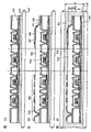
Figure 10 shows the xsect according to the ID chip of one aspect of the invention;
Each shows Figure 11 A and 11B according to the ID chip of one aspect of the invention or the xsect of IC-card;
Each shows Figure 12 A and 12B according to the ID chip of one aspect of the invention or the xsect of IC-card;
Each shows Figure 13 A and 13B according to the ID chip of one aspect of the invention or the xsect of IC-card;
Each all shows the xsect according to the light-emitting component of the ID chip of one aspect of the invention or IC-card to Figure 14 A to 14C;
Each all is the xsect according to the light-emitting component of the ID chip of one aspect of the invention or IC-card to Figure 15 A to 15C;
Each all is the xsect according to the TFT of the ID chip of one aspect of the invention or IC-card to Figure 16 A to 16C;
Figure 17 A shows the method for making a plurality of integrated circuit from big substrate to each diagram of 17D, and each described integrated circuit all is used as ID chip or the IC-card according to one aspect of the invention;
Each all shows when the shape of separating the groove that need form when being formed on an a plurality of integrated circuit on the substrate Figure 18 A to 18D;
Each all shows the ID chip that how to use according to one aspect of the invention to Figure 19 A to 19C; And
Each shows the ID chip that how to use according to one aspect of the invention Figure 20 A and 20B.
Embodiment
After this will be with reference to the accompanying drawings, describe according to the embodiments of the invention pattern.The present invention can implement with a lot of different modes, and one of ordinary skill in the art will readily recognize that under situation without departing from the spirit and scope of the present invention, pattern disclosed herein and details can be revised in every way.It should be noted that the present invention does not should be understood to the restriction that is subjected to embodiment pattern description given below.
To structure according to ID chip of the present invention be described with reference to Figure 1A and 1B.Figure 1A is the skeleton view of the ID chip of a kind of pattern according to the present invention.Reference numeral 100 expression integrated circuit, 101 expression light receiving elements, 102 expression light-emitting components, and 103 expression antennas.Light receiving element 101, light-emitting component 102 and antenna 103 all are electrically connected with integrated circuit 100.Integrated circuit 100, light receiving element 101, light-emitting component 102 and antenna 103 are formed on the substrate 104.Cladding material 105 is overlapping with substrate 104, accompanies integrated circuit 100, light receiving element 101, light-emitting component 102 and antenna 103 simultaneously therebetween.
Among Figure 1A, except integrated circuit 100, antenna 101 is clipped between substrate 104 and the cladding material 105.Yet the present invention is not limited to this structure.For example, antenna 103 can form on the surface of cladding material 105, and this surface is the one side opposite with substrate 104.Can in cladding material 105, form the perforate part, and integrated circuit 100 is electrically connected to each other by this perforate part and antenna 103.
ID chip of the present invention needn't have antenna 103.If antenna 103 is not included in the ID chip, then be provided for being electrically connected the splicing ear of antenna 103 for the ID chip.
Figure 1A shows by using cladding material 105 to strengthen the example of the physical strength of ID chip.Yet ID chip of the present invention needn't all have cladding material 105.For example, can pass through to use covering integrated circuit 100, light receiving element 101, light-emitting component 102 and antennas 103 such as resin, thereby improve the physical strength of ID chip.
The block diagram of Figure 1B shows the functional structure of the ID chip of the present invention shown in Figure 1A.
And integrated circuit 100 comprises: demodulator circuit 112 is used for the electric signal that sends from light receiving element 101 is implemented demodulation; Logical circuit 113 is carried out various arithmetical operations by using the demodulation electric signal in the demodulator circuit 112; Storer 114 is preserved the various data that comprise program; And storage control circuit 115, come the address of predetermined memory 114 and write or reading of data according to signal from logical circuit 113.In addition, use various arithmetical operations or remain on data in the storer 114, logical circuit 113 can produce the electric signal that sends to read/write device.The electric signal that produces in the logical circuit 113 is converted into light signal and sends to read/write device in light-emitting component 102.
Figure 1B shows the example of the integrated circuit 100 with a logical circuit 113, but the present invention is not limited to this structure.Content according to the arithmetical operation of carrying out in the logical circuit 113 can provide a plurality of logical circuits 113.In addition, the electric signal that comes from the light signal conversion in the light receiving element 101 can amplify amplifier 116 before it is by demodulator circuit 112 demodulation.Alternatively, the electric signal that produces in the logical circuit 113 can be exaggerated device 117 amplifications before it is sent to light-emitting component 102.
Not necessarily use a storer 114, can use a plurality of storeies.Can use various semiconductor memories, for example DRAM, SRAM, flash memory, ROM or FRAM (registered trademark).Storer 114 can be used as the operational zone when arithmetical operation.
Among Figure 1B, can comprise oscillatory circuit and modulation circuit, this oscillatory circuit can produce alternating voltage, and this modulation circuit is modulated the alternating voltage that produces in the oscillatory circuit according to the electric signal that produces in the logical circuit 113.In this case, light-emitting component 102 can convert the alternating voltage of modulation to light signal, and this light signal can be sent to read/write device.
The method that transmission is used for the radiowave of supply line voltage is not limited to the electromagnetic coupled method shown in Figure 1A and the 1B.Can use electromagnetic induction method, microwave method and other sending method.
Insulation TFT is used for integrated circuit 100.Can use various semiconductor elements, and be not limited to TFT as the semiconductor element in the integrated circuit 100.Except TFT, for example, generally can use memory element, diode, photo-electric conversion element, resistor element, coil, capacitor element, inductance etc.
Will be with reference to figure 2A, 2B and 3 structures of describing according to IC-card of the present invention.Fig. 2 A shows the outward appearance according to IC-card of the present invention.Reference numeral 201 expression card bodies, 202 expressions are installed in the pixel portion of the display device 207 in the card body 201,203 expression light receiving elements, 204 expression light-emitting components.
Fig. 2 B shows substrate 205 structures in the card body that is included in shown in Fig. 2 A.By using the film formed integrated circuit 206 of thin semiconductor film, light receiving element 203, light-emitting component 204, display device 207 and antenna 208 to be formed on the substrate 205.
Fig. 2 B shows the example that antenna 208 forms with integrated circuit 206, light receiving element 203 and light-emitting component 204, but IC-card of the present invention is not limited to this structure.The antenna that separates from integrated circuit 206 can be electrically connected with this integrated circuit 206.In this case, for example, make it to be clipped between two plastic sheetings (each plastic sheeting all have an appointment 100 μ m thickness) formed material and can be used as antenna by in coil, twining copper conductor etc. and pushing it.
An IC-card only uses an antenna 208 among Fig. 2 B, but can use a plurality of antennas 208.
Each Fig. 2 A and 2B show the structure of the IC-card with display device 207, but the present invention is not limited to this structure, and display device 207 can be provided.Yet if display device is provided, can in display device, show the data of human face photo, compare with the situation of using printing process, can make the replacement human face photo more difficult to manage.And, can show the information that is different from human face photo, can obtain the IC-card of higher functionality.
The block diagram of Fig. 3 shows the functional structure of the IC-card of the present invention shown in Fig. 2 B.
The same with the ID chip shown in Figure 1B, integrated circuit 206 comprises rectification circuit 210 and power circuit 211.Reference numeral 221 is corresponding to the capacitor between the opposite terminal that is connected antenna 208.Integrated circuit 206 comprises demodulator circuit 212, logical circuit 213, storer 214 and storage control circuit 215.And integrated circuit 206 can comprise amplifier 216, be used for before demodulator circuit 212 demodulation electric signal, amplifying this electric signal, and amplifier 217, be used for before electric signal is sent to light-emitting component 204, amplifying this electric signal.The ad hoc structure and the operation that are included in the various circuit in this integrated circuit 206 can be with reference to the descriptions of Figure 1B.
Among Fig. 3, for the IC-card of the present invention shown in Fig. 2 B, integrated circuit 206 comprises control circuit 218, is used to produce the various signals that will send to display device 207.The signal that produces in control circuit 218 is sent to the signal line drive circuit 219 and the scan line driver circuit 220 of display device 207.The operation of pixel portion 202 is subjected to the control of signal line driver circuit 219 and scan line driver circuit 220, thus can be on pixel portion 202 display image.
Notice that the IC-card shown in Fig. 3 can comprise oscillatory circuit and modulation circuit, this oscillatory circuit can produce alternating voltage, and this modulation circuit adds modulation according to the electric signal that produces in the logical circuit 213 to the alternating voltage that produces in the oscillatory circuit.In this case, light-emitting component 204 can convert the alternating voltage of modulation to light signal, and this electric signal is sent to read/write device.
The method that transmission is used for the radiowave of supply line voltage is not limited to the electromagnetic coupled method shown in Fig. 2 B and 3.Can use electromagnetic induction method, microwave method and other sending method.
Insulation TFT is used for integrated circuit 206.Can use various semiconductor elements and be not limited to TFT as the semiconductor element that uses in the integrated circuit 206.For example, except TFT, can use memory element, diode, photo-electric conversion element, resistor element, coil, capacitor element, inductor etc.
In ID chip shown in Figure 1A, 1B, 2A, the 2B and 3 or the IC-card, by the radiowave supply line voltage, but the present invention is not limited to this structure.Can use battery rather than day alignment integrated circuit supply line voltage.Only show a part that produces supply voltage in the integrated circuit in the block diagram of Fig. 4 A.Among Fig. 4 A, Reference numeral 301 is represented batteries and 302 expression power circuits.The supply voltage that use is supplied with from battery 301, power circuit can produce the supply voltage with necessary value of various circuit (highly).Notice that chemical cell, photoelectric cell etc. can be used as battery 301.
Fig. 4 B shows a kind of outward appearance of using the IC-card of solar cell 303, and this battery is a kind of photoelectric cell.By using solar cell 303 to replace battery or battery charge is used this IC-card.Except antenna, the battery of accessory power supply voltage can be used for ID chip or IC-card.
To the specific manufacture method of ID chip of the present invention be described.In the present embodiment pattern, show insulation TFT and be used as the example of the photodiode of light receiving element as semiconductor element.Yet the semiconductor element that uses in the integrated circuit is not limited to these examples, can use various circuit components.
Shown in Fig. 5 A, on thermal resistance substrate (first substrate) 500, form separating layer 501 by sputtering method.For example, can be used as first substrate 500 such as the such glass substrate of barium borosilicate glass and alumina borosilicate glass, quartz substrate, ceramic substrate etc.In addition, can use metal substrate that comprises stainless steel (SUS) substrate or the Semiconductor substrate that forms insulation film on it.Have the substrate that flexible synthetic resin (for example plastics) makes and generally have a kind of trend, wherein the temperature limitation that can bear is lower than above-mentioned substrate, but as long as it can bear treatment temperature in the manufacturing step, just can use.
Amorphous si film, polysilicon membrane, monocrystalline silicon thin film, microcrystalline silicon film (comprising half amorphous silicon membrane) that mainly comprises silicon etc. can be used for separating layer 501.Can pass through sputtering method, low pressure chemical vapor deposition method, plasma CVD method etc. and form separating layer 501.In the present embodiment pattern, the amorphous si film that thickness is approximately 50nm forms by the low pressure chemical vapor deposition method, and as separating layer 501.Separating layer 501 is not limited to silicon, and can use can be by the material of corrosion selective removal.The thickness of separating layer 501 is preferably 50nm to 60nm.The thickness of half amorphous silicon can arrive 50nm for 30nm.
On separating layer 501, form substrate film 502.It is for alkaline metal (for example Na) or the earth alkali metal that prevents to be included in first substrate 500 is diffused in the semiconductive thin film that substrate film 502 is provided, and prevents having a negative impact such as the such property of semiconductor element of TFT.In addition, substrate film 502 also has the function of protection semiconductor element in the step of later separation semiconductor element.Substrate film 502 can have individual layer or a plurality of laminated insulation film.Therefore, can be diffused into the insulation film formation substrate film 502 of semiconductive thin film by using such as monox, silicon nitride or silicon oxynitride such can prevent alkaline metal or earth alkali metal.
In the present embodiment pattern, form thickness in succession and be SiON film that the SiON film of 100nm, SiNO film that thickness is 50nm and thickness is 100nm forming substrate film 502, the material of each film, thickness, pile up number and be not limited thereto.For example, except using the SiON film, can be the silicone resin of 0.5 μ m at bottom by formation thickness such as spin coating method, slit coating, droplet method for releasing, printing processes to 3 μ m.Except the SiNO film, can form silicon nitride film (for example SiNx or Si in the middle layer
3N
4).Except the SiON film, can use SiO in the upper strata
2Film.In addition, the thickness of every layer film is preferably 0.05 μ m to 3 μ m, can freely select to the scope of 3 μ m from 0.05 μ m.
Alternatively, closing on the bottom of the substrate film 502 of separating layer 501 can be by SiON film or SiO
2Film forms, and the middle layer can be formed by silicone resin, and the upper strata can be by SiO
2Film forms.
The droplet method for releasing is that a kind of release from aperture comprises the method that the droplet of being scheduled to composition forms predetermined pattern, and it comprises ink ejecting method.Printing process comprises method for printing screen, offset printing method etc.
Can use SiH
4/ O
2, TEOS (tetraethoxysilane)/O
2Deng mixed gas, form silicon oxide film by hot CVD method, plasma CVD method, atmospheric pressure cvd method, biasing ECRCVD method etc.In addition, generally use SiH
4/ NH
3Mixed gas, form silicon nitride film by the plasma CVD method.In addition, generally use SiH
4/ N
2The mixed gas of O forms silicon oxynitride film (SiOxNy:x>y) and silicon oxynitride film (SiNxOy:x>y) by the plasma CVD method.
On substrate film 502, form semiconductive thin film 503.Preferably, after forming substrate film 502, be not exposed to atmospheric environment and form this semiconductive thin film 503.The thickness of semiconductive thin film 503 is arranged on 20 to 200nm (hope is, 40 to 170nm, more preferably, 50 to 150nm).Semiconductive thin film 503 can be amorphous semiconductor, half amorphous semiconductor or poly semiconductor.SiGe and silicon can be used as this semiconductive thin film.When using SiGe, the concentration of germanium preferably is arranged on 0.01 to 4.5 atomic percent.
Can be by this semiconductive thin film 503 of known method crystallization.Known method for crystallising has: use the laser crystal method of laser and the method for crystallising of use catalytic elements.Alternatively, can adopt method for crystallising that uses catalytic elements and the method that laser crystal method combines.When the fabulous thermal resistance substrate as quartzy is used as first substrate 500, any one uses thermal crystalline method, the ultrared lamp annealing crystallization method of use of electrical heating smelting furnace and uses the method for crystallising of catalytic elements to combine with the high annealing of about 950, as method for crystallising.
For example, in the situation of laser crystallization, before carrying out laser crystallization, semiconductive thin film 503 is carried out 1 hour thermal annealing of 500 to improve the opposing attribute of this semiconductive thin film to laser beam.Use the continuous wave solid-state laser, and shine the laser beam of the secondary of first-harmonic, thereby obtain the crystal of big crystallite dimension to four-time harmonic to semiconductive thin film.For example, usually, preferably use Nd:YVO
4Laser instrument (first-harmonic: second harmonic 1064nm) (532nm) or third harmonic (355nm).Particularly, by using nonlinear optical element, continuous wave YVO
4The laser beam that laser instrument sends is converted into harmonic wave, is the laser beam of 10W to obtain output power.Preferably, on will be, form laser beam with rectangular shape or elliptical shape by the surface of the semiconductive thin film 503 of laser beam irradiation.In this case, need about 0.01 to 100MW/cm
2(preferably, 0.1 to 10MW/cm
2) energy density.Its sweep speed is set to about 10 to 2000cm/sec so that shine this semiconductive thin film.
When the oscillation frequency of pulse laser beam is arranged on when being not less than 10MHz, can use EHF band to carry out laser crystallization, this EHF band is more much higher to the frequency band of hundreds of Hz from tens than normally used.Think to semiconductive thin film irradiated with pulse laser bundle to cycle of full solidification semiconductive thin film be that tens nanoseconds are to hundreds of nanosecond.By utilizing above-mentioned frequency band, can shine next pulse laser to semiconductive thin film, till semiconductive thin film melts owing to irradiating laser and solidifies.Therefore, because solid-liquid interface can move continuously, has in the direction of scanning semiconductive thin film of the crystal grain of growth continuously in semiconductive thin film so can form.Particularly, can obtain such grain colony: they each all have the width of 10 to 30 μ m in the direction of scanning, have the width of 1 to 5 μ m in direction perpendicular to the direction of scanning.By forming along the single grain of direction of scanning growth, the channel direction that can be formed on TFT does not almost have the semiconductive thin film of grain boundary.
For laser crystallization, the irradiation that can walk abreast of the laser of the laser of the first-harmonic of continuous wave laser and the harmonic wave of continuous wave laser.Alternatively, the laser of the harmonic wave of the laser of the first-harmonic of continuous wave laser and the pulsed laser irradiation that can walk abreast.
Can be in the inert gas such such as rare gas and nitrogen illuminating laser beam.
By above-mentioned laser beam irradiation, form semiconductive thin film 503 with enhancing crystallinity.Note, can form poly semiconductor in advance by sputtering method, plasma CVD method, hot CVD method etc.
Although semiconductive thin film 503 is by crystallization in the present embodiment pattern, can uses amorphous si film or microcrystalline semiconductor film in the technology below and do not carry out crystallization.Compare with the TFT that uses poly semiconductor, the making step number that the TFT of use amorphous semiconductor or crystallite semiconductor needs is less, like this, has the advantageous effects that reduces cost and improve output capacity.
Can decompose the acquisition amorphous semiconductor by the light discharge of waving of carrying out silicide gas.Usually, use SiH
4And Si
2H
6Example as silicide gas.These silicide gas can be by hydrogen or hydrogen and helium dilution.
Half amorphous semiconductor has the intermediate structure between impalpable structure and the crystal structure (comprising mono-crystalline structures and polycrystalline structure), and has the stable third state of free energy.This half amorphous semiconductor has the crystal structure that comprises shortrange order and lattice distortion.Can comprise and be of a size of 0.5, and it is dispersed in the non-single crystal semiconductor to the crystal grain of 20nm.For half amorphous semiconductor, Raman spectrum is to 520cm
-1The low side of wave number is offset, and observes the diffraction peak of (111) and (220) that stem from silicon crystal lattice in X-ray diffraction.And half amorphous semiconductor comprises 1% atomic percent or more hydrogen or halogen, as stopping dangling bonds.Here, for simplicity, this semiconductor is called as half amorphous semiconductor (SAS).When mixing such as the such rare gas element of helium, argon, krypton or neon to SAS (half amorphous semiconductor), lattice distortion further increases, and stability raising like this obtains good half amorphous semiconductor (SAS) thus.
The light discharge of waving by silicide gas is decomposed to form SAS.SiH
4It is typical silicide gas.Except SiH
4Outside, also can use Si
2H
6, SiH
2Cl
2, SiHCl
3, SiCl
4, SiF
4Deng as silicide gas.Silicide gas can also be selected from the mixture diluted of the rare gas element of helium, argon, krypton and neon with one or more by hydrogen or hydrogen, makes SAS form easily.Preferably dilution ratio is arranged on 1: 2 to 1: 1000.In addition, such as CH
4And C
2H
6Such carbide gas or such as GeH
4Or GeF
4Such germanium gas, perhaps F
2Deng sneaking into silicide gas, make bandwidth can be adjusted to 1.5 to 2.4eV or 0.9 to 1.1eV.
Comprise SiH in use
4And H
2Gas mixture or comprise SiH
4And F
2Under the situation of gas mixture, for example, when using amorphous semiconductor to make TFT, the subthreshold value coefficient of TFT (S value) can be set to be not more than 0.35V/sec, usually, be arranged on 0.25 to 0.09V/sec, and its mobility can be set to 10cm
2/ Vsec.For example, when forming 19 grades of ring oscillators by the TFT that uses above-mentioned half amorphous semiconductor, the supply voltage 3 to 5V can obtain to be not less than 1MHz, preferably be not less than the oscillation frequency characteristic of 100MHz.In addition, arrive under the supply voltage of 5V 3, the time-delay of every grade of phase inverter can be 26ns, is preferably 0.26ns or littler.
Shown in Fig. 5 B, graphically this semiconductive thin film 503 is to form island shape semiconductor film 504 to 507.Form the grid insulating film 508 that covers island shape semiconductor film 504 to 507.Can pass through plasma CVD method or sputtering method, form comprise silicon nitride, monox, silicon oxynitride or silicon oxynitride as the film of individual layer or lamination as grid insulating film 508.In stacked film, for example, preferably, adopt the three-decker that on substrate, stacks gradually silicon oxide film, silicon nitride film and silicon oxide film.
After forming grid insulating film 508, can be in the atmosphere that comprises 3 to 100% hydrogen carry out 1 to 12 hour thermal treatment in the temperature of 300 to 450, thus this island shape semiconductor film 504 to 507 of hydrogenation.As another kind of method for hydrogenation, can carry out plasma hydrogenation (use) by the hydrogen of plasma excitation.By this step of hydrogenation, can be by the hydrogen termination dangling bonds of thermal excitation.In the step of back,, in semiconductive thin film, form defective, the hydrogen concentration that comprises in the semiconductive thin film is arranged on 1 * 10 by hydrogenation by crooked second substrate 545 if after on semiconductor element being adhered to flexible second substrate 545
19To 1 * 10
22Atom/cm
3, preferably, be arranged on 1 * 10
19To 5 * 10
20Atom/cm
3, make these defectives can be contained in the hydrogen termination in the semiconductive thin film.In addition, halogen can be contained in the semiconductive thin film to stop these defectives.
Then, shown in Fig. 5 C, form gate electrode 509 to 512.In the present embodiment pattern, after piling up Si and W, use resist 513 to be formed by etching gate electrode 509 to 512 as mask by sputtering method.Certainly, material, structure and the manufacture method of gate electrode 509 to 512 are not limited to this, can suitably select.For example, can adopt NiSi (nickle silicide) and the rhythmo structure of the Si that adds n type impurity or the rhythmo structure of TaN (tantalum nitride) and W (tungsten).In addition, can form gate electrode with the individual layer of various conductive materials.
Can use replacement Etching masks such as SiOx mask.In this case, increase patterned step forming the mask (being called hard mask) of SiOx, SiON etc., but the thickness of comparing mask with Etching mask reduces in corrosion lessly.Like this, can form gate electrode 509 to 512 with required width.Alternatively, can optionally form gate electrode 509 to 512 and not use resist 513 by the droplet method for releasing.
Can select various materials as conductive material according to the function of conductive film.If gate electrode and antenna form simultaneously, can select material according to function.
In forming gate electrode, use caustic solution, gas CF
4, Cl
2And O
2Or Cl
2The potpourri of gas can be used as etchant gas, but etchant gas is not limited to this.
Shown in Fig. 5 D, the island shape semiconductor film 505 that will become the p channel TFT is coated with resist 514, and use gate electrode 509,511 and 512 as mask, to island shape semiconductor film 504,506 and 507 Doped n-type impurity elements (usually, phosphorus or arsenic) to form low concentration region (the first doping step).The condition of the first doping step is as follows: implantation dosage 1 * 10
13To 6 * 10
13/ cm
2, and accelerating potential 50 to 70KeV.Yet condition is not limited to this.By this first doping step, transmission grating insulation film 508 mixes, and is formed into right low concentration impurity zone 515 to 517 in island shape semiconductor film 504,506 and 507.Attention can will become the island shape semiconductor film 505 of p channel TFT and carry out the first doping step without the resist covering.
Then, as shown in Figure 6A, after by removal resists 514 such as ashing, form new resist 518 to cover the island shape semiconductor film 504,506 and 507 that will become the n channel TFT.Use gate electrode 510 as mask, the impurity element (typically, boron) that injects p type electric conductivity to island shape semiconductor film 505 is to form area with high mercury (the second doping step).The condition of the second doping step is as follows: implantation dosage 1 * 10
16To 3 * 10
16/ cm
2, accelerating potential 20 to 40KeV.By carrying out this second doping step, transmission grating insulation film 508 mixes, and is formed into right p type high concentration impurity 519 in island shape semiconductor film 505.
Then, shown in Fig. 6 B, after by removal resists 518 such as ashing, form the insulation film 520 of covering gate insulation film 508 and gate electrode 509 to 512.In the present embodiment pattern, forming thickness by the plasma CVD method is the SiO of 100nm
2Film.After this, partly corrode insulation film 520 and grid insulating film 508 by deep etch (etchback) method.Shown in Fig. 6 C, form the sidewall 521 to 524 that contacts with the sidewall of gate electrode 509 to 512 in self aligned mode.CHF
3Be used as etchant gas with the mixed gas of He.Notice that the step that forms sidewall is not limited to this.
When forming insulation film 520, there is a risk: also form insulation film at the back side of first substrate 500.In this case, the insulation film that forms at the back side of first substrate 500 can be by using resist optionally to corrode and removing.In this case, by the deep etch method, in the technology that forms sidewall 521 to 524, insulation film that the back side forms and insulation film 520 and grid insulating film 508 can be corroded and remove together.
Then, shown in Fig. 7 A, form new resist 525 to cover the island shape semiconductor film 505 that will become the p channel TFT, and use gate electrode 509,511 and 512 and sidewall 521,523 and 524 as mask, Doped n-type impurity element (usually, phosphorus or arsenic) is to form area with high mercury (the 3rd doping step).The condition of the 3rd doping step is as follows: implantation dosage: 1 * 10
13To 5 * 10
15/ cm
2, and accelerating potential: 60 to 100KeV.By carrying out the 3rd doping step, in island shape semiconductor film 504,506 and 507, be formed into right n type high concentration impurity 526 to 528.
When Doped n-type impurity when forming area with high mercury, sidewall 521,523 and 524 to form low concentration impurity zone or offset area, in the bottom of sidewall 521,523 and 524 is not carried out doping in this zone as mask.Therefore can adjust the size of sidewall 521,523 and 524 by the thickness of appropriate change insulation film 520 and the condition of the deep etch method in forming sidewall 521,523 and 524, thereby control the width of low concentration impurity zone or offset area.
After by removal resists 525 such as ashing, can implement hot activation to extrinsic region.For example, form the thick SiON film of 50nm, make it in nitrogen atmosphere, under 550 conditions, to carry out 4 hours thermal treatment then.Form the thick S iNx film that comprises hydrogen of 100nm, then, the thermal treatment that makes it to carry out 1 hour in nitrogen atmosphere under 410 ℃ condition is to proofread and correct the defective in the polycrystalline semiconductor thin film.For example, this is called the hydrogen treatment process, and it has stopped the dangling bonds in the polycrystalline semiconductor thin film.
Through above-mentioned series of steps, form n channel TFT 529,531 and 532 and p channel TFT 530.Notice that n channel TFT 531 can be used as photodiode.In the above-mentioned manufacturing step, the condition of deep etch method can suitably change, and the size of adjusting sidewall is the TFT of 0.2 μ m to 2 μ m to form channel length.Should be noted that in the present embodiment pattern,, can adopt bottom grating structure (anti-cross structure) although TFT 529 to 532 adopts top gate structure.
In addition, after this can form passivation film with protection TFT 529 to 532.Like this, preferably, passivation film is by preventing that alkaline metal or earth alkali metal from entering the silicon nitride of TFT 529 to 532, silicon oxynitride, aluminium nitride, aluminium oxide, monox etc. and forming.Particularly, for example, the SiON film that 600nm is thick can be used for this passivation film.In this case, can after forming the SiON film, carry out hydrogen treatment.Like this, on TFT 529 to 532, form insulation film SiON SiNx SiON with the three-decker of this sequence stack, but its structure or material are not limited to this.Pass through said structure, TFT 529 to 532 is coated with substrate film 502 and passivation film, further prevents from thus to be diffused into such as the such alkaline metal of Na or earth alkali metal to be used in the semiconductive thin film in the semiconductor element and to prevent negative effect to the semiconductor element characteristic.
Then, shown in Fig. 7 B, form insulation film 533 between the ground floor that covers TFT 529 to 532.The organic resin that has thermal resistance such as polyimide, acrylic acid or polyamide like this can be used for insulation film 533 between ground floor.Except organic resin, can use the material (low-k materials) of low-k or comprise resin (after this being called silicone resin) of Si-O-Si key etc.Siloxane has the framed structure of silicon (Si) and oxygen (O) key.Can use the organic group (for example alkyl or aromatic hydrocarbons) that comprises hydrogen at least as its substituting group.And, fluorine-basedly can be used as substituting group.And, comprise that at least hydrogen and fluorine-based organic group can be used as substituting group.Forming between ground floor in the insulation film 533, according to the material of layer insulation film, can use spin coating method, dipping method, spraying method, droplet method for releasing (ink ejecting method, method for printing screen, offset printing method etc.), scraper, roll coater, wash one's hair formula showering, blade coating etc.And, can use inorganic material.At this moment, can use silicon oxide film, silicon nitride film, silicon oxynitride film, PSG (phosphosilicate glass) film, PBSG (phosphorus borosilicate glass) film, BPSG (boron phosphorus silicate glass) film, aluminum oxide film etc.Notice that these insulation films can pile up to form insulation film 533 between ground floor.
And, in the present embodiment pattern, can form insulation film 534 between the second layer on the insulation film between ground floor 533.As insulation film between the second layer 534, can adopt such as the such film that comprises carbon of DLC (diamond-like-carbon) or carbonitride (CN), silicon oxide film, silicon nitride film, silicon oxynitride film etc.As the formation method, can using plasma CVD method, atmospheric plasma etc.Alternatively, can adopt photosensitive or the non-photosensitivity organic material, for example polyimide, acrylic acid, polyamide, resist and benzocyclobutene maybe can use silicone resin.
Attention can to insulation film 534 between the insulation film between ground floor 533 and the second layer at least one of them sneak into filling material to prevent since between ground floor between insulation film 533 or the second layer stress that thermal expansion coefficient difference was produced between the conductive material of insulation film 534 and the lead that forms at subsequent step etc. cause the film division of these films or ftracture.
Shown in Fig. 7 B, between ground floor, form contact hole in the insulation film 534 between the insulation film 533 and the second layer.Formation is connected to the lead 535 to 541 of TFT 529 to 532.As the etchant gas that forms contact hole, adopt CHF
3With the mixed gas of He, but the present invention is not limited to this.In the present embodiment pattern, lead 535 is formed by Al to 541.Here, can form the five-layer structure formation lead 535 to 541 of Ti, TiN, Al-Si, Ti and TiN in succession by sputter.
By in the Al layer, mixing Si, can when graphical lead, cure the generation that prevents hillock (hillock) in the process at resist.Except Si, can mix about 0.5% Cu.In addition, clamp the Al-Si layer, can further improve hillock resistance by using Ti or TiN.In graphical, preferably, adopt the hard mask of above-mentioned SiON etc.Material and the formation method of noting these leads are not limited to these, can adopt the material of above-mentioned formation gate electrode.
Lead 535 links to each other with the high concentration impurity 526 of n channel TFT 529 with 536; Lead 536 links to each other with the high concentration impurity 519 of p channel TFT 530 with 537; Lead 538 links to each other with the high concentration impurity 527 of n channel TFT 531 with 539; Lead 540 links to each other with the high concentration impurity 528 of n channel TFT 532 with 541.
Shown in Fig. 7 C, on insulation film between the second layer 534, form protective film 542 to cover lead 535 to 541.Protective seam 542 is by protecting the material of TFT 529 to 532 and lead 535 to 541 to make at subsequent step during by erosion removal separating layer 501.For example, complete coating is water-soluble or alcohol solubility epoxy resin, acryl resin or silicones to form protective seam 542.
In the present embodiment pattern, be to form protective seam 542, apply the thick water soluble resin of 30 μ m (Toagosei Co, the VL-WSHL10 that Ltd makes), and make its temporary transient curing through two minutes exposure by spin coating method.Then, this water soluble resin is also by from the UV x ray exposure x of back side illuminaton 2.5 minutes, and also from end face exposure 10 minutes, promptly exposes altogether 12.5 minutes, makes this water soluble resin full solidification, forms protective seam 542 thus.When piling up multiple organic resin, according to the solvent that is included in the organic resin, at coating or drying course, the organic resin that piles up is dissolving mutually partly, and its adhesiveness may be too high.Therefore, when insulation film between the second layer 534 and protective seam 542 by same solvent under the soluble organic resin situation about making, preferably, form inorganic insulation film (for example, the SiN that covers insulation film 534 between the second layer
xFilm, SiN
xO
yFilm, AlN
xFilm or AlN
xO
yFilm), so that in subsequent step, remove protective seam 542 reposefully.
Shown in Fig. 8 A, form groove 543, to be separated from each other I D chip.Groove 543 is sufficiently dark in to expose following separating layer 501.Can pass through cutting, scribing etc. and form groove 543.When not needing to cut apart the I D chip that forms on first substrate 500, do not need to form groove 543.
Shown in Fig. 8 B, by erosion removal separating layer 501.In the present embodiment pattern, fluoridize halogen as etchant gas, this gas is introduced from groove 543.In the present embodiment pattern, for example adopt ClF
3(chlorine trifluoride), carry out corrosion under following condition: temperature is set to 350 ℃; Flow velocity: 300sccm; Pressure: 799.8Pa (6Torr); And the time: 3 hours.And, can use the ClF that sneaks into nitrogen
3Gas.By using such as ClF
3Like this fluoridize halogen, optionally corroded separating layer 501, so can separate first substrate 500 from TFT 529 to 532.Notice that fluoridizing halogen can be gaseous state or liquid state.
Shown in Fig. 9 A, use bonding agent 544, the TFT 529 to 532 that separates is adhered to second substrate 545.The material that second substrate 545 is adhered to substrate film 502 can be used for bonding agent 544.Below the example of various types of cure adhesives, comprising: reaction cure adhesive, hot setting adhesive, such as the Photocurable adhesive of ultraviolet curing adhesive and anaerobic curing adhesive etc. can be used as bonding agent 544.
For second substrate 545, can use such as the such glass substrate of barium borosilicate glass or aluminium borosilicate glass or such as paper and the such flexible organic material of plastics.In addition, also can use flexible inorganic material.As plastic, can use the ARTON that forms by polynorbornene (making) by JSR Corporation with polar group.And following material can be used as plastic: with polyethylene terephthalate (PET), polyethersulfone (PES), naphthalenedicarboxylic acid second diester (PEN), polycarbonate (PC), nylon, polyetheretherketone (PEEK), polysulfones (PSF), polyetherimide (PEI), polyarylate (PAR), polybutylene terephthalate (PBT), polyimide, acrylonitrile butadiene styrene resin, Polyvinylchloride, polypropylene, polyvinyl acetate, acryl resin etc. is the polyester of representative.Wish that second substrate 545 has about 2 to 30W/mK high heat conductance, to disperse the heat that produces from integrated circuit.
Then, shown in Fig. 9 B, on insulation film between the second layer 534, form embankment 546 to cover lead 535 to 541.Embankment 546 has the perforate part, wherein expose portion lead 535 and 541.In addition, can use organic resin film, inorganic insulation film or siloxy group insulation film to form embankment 546.The example of organic resin film comprises propylene, polyimide, polyamide etc.The example of inorganic resin film comprises monox, silicon oxynitride etc.Particularly, the photosensitive organic resin film is used for embankment 546, forms embankment 546, makes the clinoplane that the sidewall of perforate part of exposed leads 541 has continuous curvature.Therefore, can prevent being connected of lead 541 and the electrode 548 that formed afterwards.At this moment, can form mask by droplet method for releasing or printing process.Alternatively, embankment 546 can form by droplet method for releasing or printing process itself.
Then, form light-emitting component 549 or antenna 550.The present embodiment pattern shows a kind of pattern that at first forms light-emitting component 549, can form simultaneously with the electrode 548 that forms light-emitting component 549 but can at first form antenna 550 or antenna 550.
Before forming, can in atmospheric atmosphere, carry out thermal treatment or carry out thermal treatment (vacuum(-)baking), with the water of removing embankment 546 and lead 541 absorptions, oxygen etc. at vacuum atmosphere corresponding to the electroluminescence layer 547 of carrying out photoelectric conversion layer.Particularly, carry out about 0.5 to 20 hour thermal treatment in vacuum, underlayer temperature is 200 to 450 ℃, is preferably 250 ℃ to 300 ℃.Hope is provided with 3 * 10 with vacuum
-7Torr or lower, most preferably, as might most preferably being set to 3 * 10
-8Torr or lower.When electroluminescence layer 547 forms after vacuum is carried out thermal treatment, before forming electroluminescence layer 547, substrate is arranged on vacuum, can further improve reliability.Will be in order to make as the surfacingization of the lead 541 of male or female, before forming vacuum(-)baking, can use polyvinyl alcohol (PVA) porous body etc. that this surface is cleaned and polished by the CMP method.In addition, by after the CMP method polishing, will be exposed to ultraviolet irradiation, oxyanion precursor processing etc. as the surface of the lead 541 of male or female.
Form the electroluminescence layer 547 that the lead 541 in the perforate partly with embankment 546 contacts.Electroluminescence layer 547 can form with individual layer or lamination.In the present embodiment pattern, because lead 541 as negative electrode, when forming electroluminescence layer 547 by multilayer, stacks gradually electron injecting layer, electron transfer layer, luminescent layer, hole transmission layer and hole injection layer on lead 541.If note lead 541, pile up hole injection layer, hole transmission layer, luminescent layer, electron transfer layer and electron injecting layer in succession to form electroluminescence layer 547 as anode.
Note,, can form the light-emitting component 549 of emission infrared light by rhythmo structure that suitably changes electroluminescence layer 547 and the electroluminescent material that is used for these layers.
Can provide color filter to have the light of particular range of wavelengths with emission.Color filter comprises the nonferrous layer that can transmit particular range of wavelengths light, perhaps except nonferrous layer, comprises the shielded film that can shield visible light.Color filter can form on the cladding material that is used for the sealed light emitting element, or forms on substrate.In each case, can be formed with chromatograph or shielded film by printing process or droplet method for releasing.
Form the electrode 548 that covers electroluminescence layer 547.When lead 541 was used as negative electrode, electrode 548 was as anode.In contrast, when lead 541 was used as anode, electrode 548 was as negative electrode.According to material, the manufacture method of electrode 548 preferably is selected from evaporation deposition method, sputtering method, droplet method for releasing etc.
Even still can form electroluminescence layer 547 during any compound below using: high molecular organic compound, middle molecular weight organic compound, low molecular weight organic compound and mineral compound by the droplet method for releasing.Can form middle molecular weight organic compound, low molecular weight organic compound and mineral compound by gas-phase deposition method.Note electroluminescence layer 547 and electrode 548 with the regional different zone that formed antenna 550 afterwards in form.
Other light transmitting conductive oxide material such such as the zinc paste (GZO) of tin indium oxide (ITO), zinc paste (ZnO), indium zinc oxide (IZO) and doped gallium can be used as anode.And, can form anode by the indium oxide that use comprises the tin indium oxide (after this being called ITSO) of I TO and monox and comprises monox (wherein having mixed 2 to 20% zinc paste (ZnO)).Except being used for other light transmitting conductive oxide material of anode, for example, can adopt the individual layer of one or more TiN, ZrN, Ti, W, Ni, Pt, Cr, Ag and Al; Titanium nitride membrane and mainly comprise the lamination of the film of aluminium; Titanium nitride membrane, mainly comprise the film of aluminium and three layer laminate of titanium nitride membrane etc.Notice that when the anode one end extraction light time of the material that is different from the light transmitting conductive oxide material from use, the anode of formation has enough film thicknesses (preferably, about 5nm is to 30nm) of transmission light.
Negative electrode can be formed by metal, alloy, conductive compound or these mixtures of material, and these materials all have low work function.Particularly, negative electrode can be formed by material beneath: such as Li or the such alkaline metal of Cs; Such as Ca, S r or the such earth alkali metal of Mg; The alloy (for example Mg:Ag, A l:Li or Mg:In) that comprises these materials; The compound of these materials (CaF for example
2Or CaN); Or such as Yb or the such rare earth metal of Er.When electron injecting layer is provided, can use another conductive layer such as A l.When launching the light time from negative electrode one end, negative electrode can be formed by another kind of light transmitting conductive oxide material, for example the zinc paste (GZO) of tin indium oxide (ITO), zinc paste (ZnO), indium zinc oxide (IZO) or doped gallium.And negative electrode can form by tin indium oxide (ITSO) that comprises ITO and monox or the indium oxide that comprises monox (wherein having mixed 2 to 20% zinc paste (ZnO)).Under the situation of using this light transmitting conductive oxide material, preferably in electroluminescence layer 547, provide electron injecting layer.Form the transparent cathode of enough thick (preferably about 5nm is to 30nm) and do not use the light transmitting conductive oxide material, can extract light from negative electrode one end.In this case, use the light transmitting conductive oxide material,, can suppress the sheet resistance of negative electrode by forming the transparent conducting thin film that contacts with the top or the bottom of negative electrode.
Lead 541, electroluminescence layer 547 and electrode 548 are overlapping to form light-emitting component 549 in the perforate part of embankment 546.
Come the light of self-emission device 549 can be, extract from electrode 548 1 ends or from opposite end from lead 541 1 ends.Depend on required structure, the material of each anode and negative electrode and thickness are selected from these three kinds of structures.
The manufacture method of antenna 550 is described below.Antenna 550 can form by the patterned conductive film in the electrode 548 that forms light-emitting component 549, maybe can form by another kind of manufacture method.The method that the present embodiment pattern shows a manufacture method by being different from electrode 548 forms the example of antenna 550.
Shown in Fig. 9 B, on embankment 546, form antenna 550.Can use conductive material to form antenna 519, this conductive material comprises one or more such as Ag, Au, Cu, Pd, Cr, Mo, Ti, Ta, W, Al, Fe, Co, Zn, Sn and Ni such metal or its metallic compound.Antenna 550 links to each other with lead 535.Although notice that antenna 550 directly links to each other with lead 535 in Fig. 9 B, ID chip of the present invention is not limited to this structure.For example, can use the lead of independent formation that antenna 550 is electrically connected with lead 535.
Can form antenna 550 by printing process, photoetching, vapor deposition, droplet method for releasing etc.Although antenna 550 uses the individual layer conductive film to form in the present embodiment pattern, it can form by piling up a plurality of conductive films.For example, the lead that uses Ni etc. to form covers Cu to form antenna 550 by electroless-plating.
Use printing process or droplet method for releasing, can not use exposed mask to form antenna 550.Different with photoetching situation (causing spillage of material by corrosion), droplet method for releasing and printing process can more effectively utilize material.In addition, because do not need to use expensive exposed mask, therefore can reduce the manufacturing cost of ID chip.
When using droplet method for releasing or various printing process, for example, also can use by covering the conductive particle that Cu obtains with Ag.In the situation that forms antenna 550 by the droplet method for releasing,, wish the surface of embankment 546 is handled for strengthening the adhesion of antenna 550.
In order to increase adherence, for example, can make in the following method: make metal or metallic compound adhere to the surface of embankment 546, this metal or metallic compound are because catalytic action can strengthen the adhesion of conductive film or insulation film; Organic insulation film, metal and the metallic compound that the conductive film that will form or insulation film are had good adhesion adheres to the surface of embankment 546; Thereby change its surface properties by under atmospheric pressure or reduced pressure, Cement Composite Treated by Plasma being carried out on the surface of embankment 546.Metal to conductive film or insulation film have excellent adhesion can use titanium, titanium dioxide or 3d transitional element for example Sc, Ti, V, Cr, Mn, Fe, Co, Ni, Cu, Zn etc.For metallic compound, can use oxide, nitride, oxynitride of above-mentioned metal etc.For above-mentioned organic insulation film, quote polyimide, silicone resin etc. as an example.
Have under the situation of electric conductivity at metal that adheres to embankment 546 or metallic compound, the control sheet resistance is not to hinder the proper operation of antenna.Particularly, for example, have the metal of electric conductivity or the average thickness of metallic compound and be controlled at 1 to 10nm.Metal or metallic compound can be by oxidations partly or entirely and are insulated.Alternatively, the zone outside the zone that adhesion need improve, the metal of adhesion or metallic compound can optionally be removed by corrosion.Can be by using droplet method for releasing, printing process, sol-gel method etc., only optionally adhesiving metal or metallic compound in the specific region, rather than on the whole surface of substrate, adhere in advance.Metal or metallic compound needn't have as the complete continuous shape of film on embankment 546 surfaces, can disperse to a certain extent.
After forming light-emitting component 549 and antenna 550, can form the protective film of covering luminous element 549 or antenna 550.More can prevent such as the such film that causes the material infiltration that light-emitting component worsens of water or oxygen as protective film than other insulating material.Usually, preferably can use the DLC film that forms by RF sputter or CVD method, carbon nitride films, silicon nitride film etc.The film that the film that carbon nitride films and silicon nitride film pile up, polystyrene pile up etc. can be used for this protective film.In addition, can use the infiltration of anti-sealing or oxygen film and than above-mentioned film see through more water or oxygen but the lamination of the low film of internal stress as this protective film.Adopt silicon nitride film in the present embodiment pattern.When silicon nitride film when the protective film, can be included in the reacting gas and can sneak into protective film such as the such rare gas element of Ar, under low deposition temperature, to form good protective film.
Shown in Fig. 9 C, applying adhesive 551 is with covering luminous element 549 and antenna 550 on embankment 546, and then, cladding material 552 adheres to it.Can use with second substrate, 545 identical materials and form cladding material 552.For example the thickness of bonding agent 551 can be 10 to 200 μ m for example.
The material that cladding material 552 and embankment 546 and antenna 550 are adhered to together is used for bonding agent 551.As bonding agent 551, for example, can use various cure adhesives, comprise reaction cure adhesive, hot setting adhesive, such as the such Photocurable adhesive of ultraviolet curing adhesive, anaerobic curing adhesive etc.
By above-mentioned each step, finished the ID chip.By this manufacture method, can between second substrate 545 and cladding material 552, form integrated circuit as thin as a wafer, its gross thickness be 0.3 μ m to 3 μ m, generally be approximately 2 μ m.Except the thickness of semiconductor element self, the thickness of integrated circuit also is included in the various insulation films of formation between bonding agent 544 and the bonding agent 551 and the thickness of layer insulation film.The area that is included in the integrated circuit in the ID chip can be not more than 5mm * 5mm (25mm
2), be preferably about 0.3mm * 0.3mm (0.09mm
2) to 4mm * 4mm (16mm
2).
By integrated circuit being placed on the position at center between next-door neighbour's second substrate 545 and the cladding material 552, can strengthen the physical strength of I D chip.Particularly, when the distance between second substrate 545 and the cladding material 552 was d, preferably, the thickness of control bonding agent 544 and bonding agent 551 made formula 1 below the satisfying apart from x between the center O of thickness direction integrated circuit and second substrate 545.
More preferably, the thickness of control bonding agent 544 and bonding agent 551 makes it satisfy following formula 2.
Formula 2
As shown in figure 10, between substrate film 502, ground floor between insulation film 533, the second layer thickness of insulation film 534 or embankment 546 can adjust, make between the substrate film of the island shape semiconductor film of TFT and bottom apart from t
Under, and between island shape semiconductor film and the embankment 546 apart from t
OverEqual or equal substantially in integrated circuit.By island shape semiconductor film being placed on the centre of integrated circuit, the stress that applies on the semiconductor layer can discharge, and can prevent the generation in crack.
Among Fig. 9 C, show the example that uses cladding material 552, but the present invention is not limited to this structure.For example, the step shown in Fig. 9 B can be last step, or after finishing the step shown in Fig. 9 B, can form the layer of protection antenna 550 and light-emitting component 549, finishes integrated circuit thus.
Illustrated in the present embodiment pattern by between first substrate 500 of high thermal resistance and integrated circuit, providing separating layer, and by the erosion removal separating layer and from the method for substrate separation integrated circuit, yet, be not limited to this according to the method for manufacturing ID chip of the present invention.For example, can between high thermal resistance substrate and integrated circuit, provide metal-oxide film, and crystallization this metal-oxide film that weakens, make integrated circuit from substrate separation.Alternatively, can provide the separating layer of the amorphous semiconductor film formation that comprises hydrogen between high thermal resistance substrate and integrated circuit, and remove separating layer by laser radiation, making can be from the substrate separation integrated circuit.Alternatively, the high thermal resistance substrate that forms integrated circuit on it can mechanically be removed or by using solution or gas to corrode elimination, thereby from the substrate separation integrated circuit.
When organic resin as the bonding agent 544 that contacts with substrate film 502 when guaranteeing the pliability of I D chip, by using silicon nitride film or silicon oxynitride film, can prevent to be diffused into semiconductive thin film from organic resin such as Na such alkaline metal or earth alkali metal as substrate film 502.
When the ID adhesive die attachment when having the object of curved surface, this curved surface is produced by the bus on trochoidal surface, the cylindrical surface etc., second substrate 545 of this ID chip also is crooked, and preferably, the direction of bus is identical with the charge carrier moving direction of TFT 529 to 532.According to this structure, the bending that can prevent second substrate 545 has a negative impact to the characteristic of TFT 529 to 532.When the area ratio that makes island shape semiconductor film in integrated circuit is arranged on 1 to 30%,, still can suppress the suffered negative effect of TFT 529 to 532 characteristics even second substrate 545 is crooked.
The example that forms antenna and integrated circuit on identical substrate has been described in the present embodiment pattern.Yet the present invention is not limited to this structure.The antenna that forms on a substrate can be electrically connected to each other with the integrated circuit that forms on another substrate.In the present embodiment pattern, show the example that on embankment 546, forms antenna 550 and light-emitting component 549.Yet the present invention is not limited to this structure, and antenna 550 and light-emitting component 549 can form on different layers.
Usually, the radiowave of ID chip use 13.56MHz or 2.45GHz frequency under a lot of situations.Therefore, be the versatility of Extended ID chip, the I D chip that formation can detect the radiowave of said frequencies is and is important.
Compare with the ID chip that uses Semiconductor substrate to form, the ID chip of present embodiment pattern has radiowave by the advantage of less shielding, can prevent the signal attenuation that is caused by the radiowave that shields like this.Therefore, because do not need Semiconductor substrate, the cost of ID chip can sharply reduce.For example, compared situation and the use 730 * 920mm that uses 12 inches silicon substrates
2The situation of glass substrate.The area of silicon substrate approximately is 73000mm
2, and the area of glass substrate is approximately 672000mm
2, that is, glass substrate approximately is that 9.2 times of silicon substrate are big.When not considering to cut substrate redundant, area is approximately 672000mm
2Glass substrate on, can form about 672000 areas is 1mm
2I D chip.It approximately is 9.2 times of formed ID chip on the silicon substrate.Manufacturing step is of a size of 730 * 920mm using still less
2The situation of glass substrate, be that the situation of 12 inches silicon substrates is compared with using diameter, the equipment investment that is used for large-scale production ID chip can reduce 1/3rd.And according to the present invention, after glass substrate is separated integrated circuit, glass substrate can be utilized again.Therefore, even the pricing that will compensate broken glass substrate and purify glass substrate surface interior, uses the situation of glass substrate more much smaller than the required cost of situation that uses silicon substrate.Even glass substrate does not re-use and is dropped, be of a size of 730 * 920mm
2The price of glass substrate approximately be half of 12 inch diameter silicon substrate prices.Therefore, the cost of clearly making the ID chip can greatly reduce.
Like this, use 730 * 920mm
2The ID chip price of glass substrate can approximately be reduced to use diameter be 12 inches silicon substrates the ID chip price a thirtieth.Because expectation is that the ID chip can arbitrarily use, therefore, the ID chip of the present invention that cost greatly reduces is effectively for this application.
In the present embodiment pattern, it is separated and adhere to the example of flexible substrate to show integrated circuit.Yet the present invention is not limited to this structure.For example, if use such as glass substrate such can bear heat treated thermal resistance substrate in the integrated circuit manufacturing step, then needn't separate integrated circuit.
In addition, IC-card of the present invention can form with reference to above-mentioned manufacture method.Notice that this display device can form and adhere to second substrate discretely with integrated circuit, or this display device can form and adhere to second substrate with integrated circuit when IC-card has display device.
Shown in Figure 11 A, in the ID chip of present embodiment, form embankment 1200, and the part of each lead 1201 and 1202 exposes partly in perforate with perforate part.
On embankment 1200, form bonding agent 1207 with covering terminal 1203, and cladding material 1208 is adhered to embankment 1200 by bonding agent 1207.Anisotropic conductive resin can be used for bonding agent 1207.
On cladding material 1208, be pre-formed antenna 1209.On the opposing face of the embankment 1200 of cladding material 1208, form antenna 1209.The contact holes exposing that the part of antenna 1209 is passed through to form in the cladding material 1208 is in terminal 1203.Notice that antenna 1209 can form at embankment 1,200 one ends of cladding material 1208.By using anisotropic conductive resin as bonding agent 1207, antenna 1209 and terminal 1203 can be electrically connected to each other.
Anisotropic conductive resin is that a kind of conductive material is dispersed in the material in the resin.Following example can be used as resin: heat reactive resin, for example epoxy resin, urethane resin and acryl resin; Thermoplastic resin, for example polyvinyl resin and acrylic resin; Silicone resin etc.As conductive material, for example, can use: plastic grain, for example polystyrene and the epoxy resin electroplated by Ni, Au etc.; Such as Ni, Au, Ag, the such metallic particles of scolding tin; Particulate or fibrous carbon are electroplated the fiber Ni of Au etc.The size of conductive material is determined in hope according to the distance between antenna 1209 and the terminal 1203.
By applying ultrasound wave to anisotropic conductive resin, make antenna 1209 and terminal 1203 air pressure bonding (pressure bonding) each other, perhaps solidify anisotropic conductive resin by irradiating ultraviolet light, make antenna 1209 and terminal 1203 air pressure bonding each other.
Although present embodiment shows the example that the bonding agent 1207 that uses anisotropic conductive resin to make is electrically connected antenna 1209 and terminal 1203, the present invention is not limited to this structure.As the substitute of bonding agent 1207, antenna 1209 and terminal 1203 are electrically connected by air pressure bonding anisotropic conducting film.
Although it is separated and adhere to the example of flexible substrate that present embodiment shows integrated circuit, yet the present invention is not limited to this structure.For example, can bear in the integrated circuit fabrication process heat treatedly during, needn't separate integrated circuit such as the such substrate of glass substrate when using.The sectional view of Figure 11 B has illustrated the sectional view of the I D chip of a kind of pattern of using glass substrate formation.
In the I D chip shown in Figure 11 B, glass substrate is as substrate 1210.Do not have adhesive clip between semiconductor element 1211 to 1214 that is used for integrated circuit and substrate 1210, therefore, the substrate 1210 and the substrate film 1215 of formation contact with each other.In this structure, can not enter in the semiconductive thin film that is included in semiconductor element 1211 to 1214 such as the such alkaline metal of Na, earth alkali metal, moisture etc.
Embodiment 2
Embodiment 2 has described the example of the photodiode that uses in ID chip of the present invention or IC-card.
Figure 12 A shows the ID chip of present embodiment or the sectional view of IC-card.Among Figure 12 A, photodiode 1500 forms on insulation film between the second layer 1501, and the TFT 1502 that is used to control the driving of photodiode 1500 is covered by insulation film between the insulation film between ground floor 1503 and the second layer 1501.Although TFT 1502 by two layer insulation films be between ground floor between insulation film 1503 and the second layer insulation film 1501 cover, present embodiment is not limited to this structure.TFT 1502 can also coverlets layer by layer between insulation film or three layers or more multi-layered layer insulation film cover.
Notice that negative electrode 1504, photoelectric conversion layer 1505 and anode 1506 can have single layer structure or rhythmo structure.
Shown in Figure 12 B, provide the shielded film 1513 of shielded from light at a relative end with respect to the substrate 1510 of photodiode 1511.Like this, can limit the direction of light that enters photodiode 1511.Metallic film that can shielded from light, the resin etc. that adds pigment can be used for shielded film 1513.
Among Figure 12 B, be directed into the opposite end of substrate, form shielded film 1513 and make the light from substrate 1,510 one ends preferably enter photodiode 1511 from the light of light-emitting component 1512 emission.Yet the present invention is not limited to this structure.The position that forms shielded film 1513 is not limited to the position shown in Figure 12 B.In addition, for the direction of light of light-emitting component 1512 emissions, light can be not limited to the structure shown in Figure 12 B to substrate 1510 transmissions.
Note,, still can form shielded film 1513 even use photodiode with the structure shown in the embodiment pattern.
The photodiode that uses in ID chip of the present invention or the IC-card is not limited to the structure of present embodiment.
Present embodiment can combine with embodiment 1.
Embodiment 3
To explain by the ID chip under graphical a kind of conductive film formation and the lead situation that TFT links to each other with antenna or the structure of IC-card with reference to figure 13A.Figure 13 A is according to the ID chip of present embodiment or the sectional view of IC-card.
Among Figure 13 A, Reference numeral 1401 expressions are used to control the TFT of light-emitting component 1409 operations.TFT 1401 comprises island shape semiconductor film 1402, the grid insulating film 1403 that contacts with island shape semiconductor film 1402 and the gate electrode 1404 overlapping with this island shape semiconductor film 1402, accompanies grid insulating film 1403 therebetween.TFT 1401 is coated with insulation film 1406 between 1 the exhausted film 1405 of ground floor and the second layer.In the present embodiment, TFT 1401 is coated with two layer insulation films, i.e. insulation film 1406 between the insulation film 1405 and the second layer between ground floor.Yet present embodiment is not limited to this structure.TFT 1401 can be coated with individual layer or three layers or more multi-layered layer insulation film.
The lead 1407 that forms on the insulation film 1406 between the second layer links to each other with island shape semiconductor film 1402 by the contact hole that forms in the insulation film 1406 between insulation film 1405 between ground floor and the second layer.
On insulation film between the second layer 1406, form antenna 1408.Conductive film is formed between the second layer on the insulation film 1406 and by graphically to form lead 1407 and antenna 1408.By forming antenna 1408, can reduce the number of the manufacturing step of ID chip or IC-card together with lead 1407.
Then, will explain gate electrode and the ID chip under the antenna situation or the structure of IC-card that forms TFT by a graphical conductive film with reference to figure 13B.Figure 13 B is according to the ID chip of present embodiment or the sectional view of IC-card.
Among Figure 13 B, Reference numeral 1411 expressions are used to control the TFT of light-emitting component 1419 operations.TFT 1411 comprise island shape semiconductor film 1412, with overlapping grid insulating film 1413 of this island shape semiconductor film 1412 and the gate electrode 1414 overlapping with this island shape semiconductor film 1412, accompany grid insulating film 1413 therebetween.On grid insulating film 1413, form antenna 1418.Conductive film forms on grid insulating film 1413 and by graphically to form gate electrode 1414 and antenna 1418.By forming antenna 1418, can reduce the number of the manufacturing step of ID chip or IC-card with gate electrode 1414.
In the present embodiment pattern, it is separated and adhere to example on the substrate of independent preparation to show integrated circuit.Yet the present invention is not limited to this structure.For example, if use such as glass substrate such can bear heat treated thermal resistance substrate in the integrated circuit manufacturing step, then needn't separate integrated circuit.
Embodiment 4
With reference to figure 14A to 14C, the cross-section structure of the pixel the when TFT of embodiment 4 description control light-emitting components operations is the p type.Note, at Figure 14 A in 14C, be included in two electrodes in the light-emitting component with TFT directly or an electrode (first electrode) that is electrically connected be anode, another electrode (second electrode) is a negative electrode, can be anode but first electrode can be the negative electrode and second electrode.
Figure 14 A shows the sectional view of pixel under the situation about only extracting from first electrode, 6,004 one ends that TFT 6001 is 6003 emissions of p type and light-emitting component.Among Figure 14 A, first electrode 6004 of light-emitting component 6003 is electrically connected with TFT 6001 by lead 6009.Yet the present invention is not limited to this structure.The part of the lead 6009 that directly links to each other with TFT 6001 can be used as first electrode 6004.
TFT 6001 is coated with between ground floor insulation film 6002 between insulation film 6007 and the second layer.Although among Figure 14 A, TFT 6001 is by two layer insulation films, promptly between ground floor between the insulation film 6007 and the second layer insulation film 6002 cover, yet the present invention is not limited to this structure.TFT 6001 can be coated with individual layer layer insulation film or three layers or more multi-layered layer insulation film.
On insulation film between the second layer 6002, form embankment 6008 with perforate part.The part of first electrode 6004 exposes in the perforate part of embankment 6008, and first electrode 6004, electroluminescence layer 6005 and second electrode 6006 pile up in succession.
Among Figure 14 A, first electrode 6004 is anodes, and second electrode 6006 is negative electrodes.The material that is suitable for each anode and negative electrode can the reference example pattern.Attention by use can printing opacity material or thickness form first electrode 6004.Can reflect or the material or the thickness of shielded from light form second electrode 6006 by using.
The electroluminescence layer 6005 that forms has single or multiple lift.Under the situation of sandwich construction, consider carrier transmission characteristics, following layer can be classified into hole injection layer, hole transmission layer, luminescent layer, electron transfer layer, electron injecting layer etc.When electroluminescence layer 6005 except having luminescent layer, also have following any one deck: when hole injection layer, hole transmission layer, electron transfer layer and electron injecting layer, hole injection layer, hole transmission layer, luminescent layer, electron transfer layer, electron injecting layer pile up on first electrode 6004 with this order.Note can not clearly distinguishing the border under not necessarily clear and some situation in the border of each layer, this is partly to sneak into adjacent layer because form the material of each layer.Every layer can be formed by organic material or inorganic material.For organic material, can use any high molecular weight material, middle molecular weight material and low molecular weight material.Molecular weight material represents that the number (extent of polymerization) of constitutional repeating unit is approximately 2 to 20 low polymer in the attention.Difference clearly between hole injection layer and hole transmission layer, they the two must have hole transport attribute (hole mobility).Hole injection layer contacts with anode, and for simplicity, the layer that contacts with hole injection layer is divided into hole transmission layer.Identical for electron transfer layer with the electron injecting layer situation.The layer that contacts with negative electrode be called electron injecting layer and contact with electron injecting layer layer be called electron transfer layer.Luminescent layer has the function of electron transfer layer in some situation, and therefore, it is also referred to as the luminous electron transport layer.
Under the situation of pixel shown in Figure 14 A, the light of light-emitting component 6003 emissions can extract from first electrode, 6,004 one ends, as the arrow of describing shown in.
Figure 14 B illustrates the sectional view that TFT 6011 is pixels under the light of p type and the light-emitting component 6013 emissions situation about extracting from second electrode, 6,016 one ends.Among Figure 14 B, the part of the lead that directly links to each other with TFT 6011 is as first electrode 6014.Yet the present invention is not limited to this structure.First electrode 6014 of light-emitting component 6013 can be electrically connected with TFT 6011 by the lead that forms separately.
On first electrode 6014, pile up the electroluminescence layer 6015 and second electrode 6016 in succession.Among Figure 14 B, first electrode 6014 is that the anode and second electrode 6016 are negative electrodes.The material that is suitable for each anode and negative electrode can the reference example pattern.Attention can be reflected by use or the material or the thickness of shielded from light form first electrode 6014.Use can printing opacity material or thickness form second electrode 6016.
Electroluminescence layer 6015 can form with the method identical with the electroluminescence layer 6005 shown in Figure 14 A.Under the situation of pixel shown in Figure 14 B, the light of light-emitting component 6013 emissions extracts from second electrode, 6,016 one ends, as the arrow of describing shown in.
Figure 14 C illustrates the sectional view of pixel under the situation about only extracting from the opposite end of first electrode 6024 and second electrode 6026 that TFT 6021 is 6023 emissions of p type and light-emitting component.Although Figure 14 C shows the structure that first electrode 6024 of light-emitting component 6023 is electrically connected with TFT 6021 by lead 6029, the present invention is not limited to this structure.The part of the lead 6029 that directly links to each other with TFT 6021 can be used as first electrode 6024.。
On first electrode 6024, pile up the electroluminescence layer 6025 and second electrode 6026 in succession.Among Figure 14 C, first electrode 6024 is that the anode and second electrode 6026 are negative electrodes.The material that is suitable for each anode and negative electrode can the reference example pattern.Note to use can printing opacity material or thickness form first electrode 6024 and second electrode 6026.
Electroluminescence layer 6025 can form with the method identical with the electroluminescence layer 6005 shown in Figure 14 A.In the situation of the pixel shown in Figure 14 C, what light-emitting component 6023 was launched only extracts from first electrode 6024 and second electrode, 6026 opposite end, as the arrow of describing shown in.
In the present embodiment, each TFT 6001,6011 and 6021 has the structure (double-gate structure) of two gate electrodes, wherein two TFT series connection.Yet present embodiment is not limited to this structure.Can use the single grid structure that comprises a gate electrode or have the multi-gate structure of the three or more TFT series connection of three or more gate electrodes.
Embodiment 5
Cross-section structure with reference to the pixel of figure 15A when the TFT of 15C description control light-emitting component operation is the n type.Note, in 15C, a kind of situation is shown at Figure 15 A, consider two electrodes of light-emitting component, an electrode (first electrode) direct with TFT or that be electrically connected is a negative electrode, and another electrode (second electrode) is an anode, can be negative electrode but first electrode can be the anode and second electrode.
Figure 15 A shows the sectional view that TFT 6031 is light pixels when first electrode, 6,034 one ends extract of n type and light-emitting component 6033 emissions.Among Figure 15 A, first electrode 6034 of light-emitting component 6033 is electrically connected with TFT 6031 by lead 6039.Yet the present invention is not limited to this structure.The part of the lead 6039 that directly links to each other with TFT 6031 can be used as first electrode 6034.
On first electrode 6034, pile up the electroluminescence layer 6035 and second electrode 6036 in succession.Among Figure 15 A, first electrode 6034 is negative electrodes, and second electrode 6036 is anodes.The material that is suitable for each anode and negative electrode can the reference example pattern.Note to use can printing opacity material or thickness form first electrode 6034.Use can be reflected or the material or the thickness of shielded from light form second electrode 6036.
Under the situation of pixel shown in Figure 15 A, the light of light-emitting component 6033 emissions can extract from first electrode, 6,034 one ends, as the arrow of describing shown in.
Figure 15 B shows the only sectional view of pixel under second electrode, the 6046 one end extraction situations that TFT 6041 is 6043 emissions of n type and light-emitting component.Among Figure 15 B, the part of the lead that directly links to each other with TFT 6041 is as first electrode 6044.Yet the present invention is not limited to this structure.First electrode 6044 of light-emitting component 6043 can be electrically connected with TFT 6041 by the lead that forms separately.
On first electrode 6044, pile up the electroluminescence layer 6045 and second electrode 6046 in succession.Among Figure 15 B, first electrode 6044 is that the negative electrode and second electrode 6046 are anodes.The material that is suitable for each anode and negative electrode can the reference example pattern.Notice that use can be reflected or the material or the thickness of shielded from light form first electrode 6044.Use can printing opacity material or thickness form second electrode 6046.
It is only sectional views of pixel under the opposite end extraction situation of first electrode 6054 and second electrode 6056 of n type and light-emitting component 6053 emissions that Figure 15 C shows at TFT 6051.Although Figure 15 C shows the structure that first electrode 6054 of light-emitting component 6053 is electrically connected with TFT 6051 by lead 6059, the present invention is not limited to this structure.The part of the lead 6059 that directly links to each other with TFT 6051 can be used as first electrode 6054.
On first electrode 6054, pile up the electroluminescence layer 6055 and second electrode 6056 in succession.Among Figure 15 C, first electrode 6054 is that the negative electrode and second electrode 6056 are anodes.The material that is suitable for each anode and negative electrode can the reference example pattern.Attention by use can printing opacity material or thickness form first electrode 6054 and second electrode 6056.
In the present embodiment, each TFT 6031,6041,6051 has the structure (double-gate structure) of two gate electrodes, wherein two TFT series connection.Yet present embodiment is not limited to this structure.Can use the single grid structure that comprises a gate electrode or have the multi-gate structure of three or more gate electrodes (wherein three or more TFT series connection).
Embodiment 6
Embodiment 6 is used for explanation the structure of the TFT of ID chip of the present invention or IC-card.
Figure 16 A shows the sectional view according to the TFT of present embodiment.Reference numeral 701 expression n channel TFT; And 702 expression p channel TFT.The structure of n channel TFT 701 will be explained as an example.
Although gate electrode 707 comprises two-layer conductive film 707a and 707b in the present embodiment, the present invention is not limited to this structure.Gate electrode 707 can comprise the conductive film that the individual layer conductive film is two-layer or more multi-layered.Gate electrode 707 is overlapping with the channel formation region territory 704 of island shape semiconductor film 705, accompanies grid insulating film 706 therebetween.Sidewall 708 and 709 and two LDD zone 710 of island shape semiconductor film 705 overlapping, accompany gate insulation layer 706 therebetween.
For example, can be the silicon oxide film formation sidewall 708 of 100nm by corrosion thickness, and can be LTO film (a kind of low temperature oxide film) the formation sidewall 709 of 200nm by corrosion thickness.In the present embodiment, be formed for the silicon oxide film of sidewall 708, be formed for the LTO film of sidewall 709 by the low pressure chemical vapor deposition method by the plasma CVD method.Although notice that silicon oxide film can comprise nitrogen, the number of nitrogen-atoms must be arranged to lower than the number of oxygen atom.
Use gate electrode 707 as mask after island shape semiconductor film 705 Doped n-type impurity, form sidewall 708 and 709, utilize sidewall 708 and 709 as mask to island shape semiconductor film 705 Doped n-type impurity elements, thereby form extrinsic region 703 and LDD zone 710 respectively.
Figure 16 B shows a kind of situation, and wherein each TFT among Figure 16 A has the individual layer sidewall.Shown in Figure 16 B, each n channel TFT 721 and p channel TFT 722 comprise individual layer sidewall 728 and individual layer sidewall 729 respectively.For example, can by corrosion thickness the silicon oxide film formation sidewall 728 and 729 of 100nm.In the present embodiment, the silicon oxide film that is used for sidewall 728 and 729 forms by the plasma CVD method.Silicon oxide film can comprise nitrogen; But the number of nitrogen-atoms must be arranged to lower than the number of oxygen atom.
Figure 16 C shows the structure of bottom gate TFT.Reference numeral 741 expression n channel TFT, 742 expression p channel TFT.N channel TFT 741 will be explained as an example.
Among Figure 16 C, n channel TFT 741 comprises island shape semiconductor film 745.Island shape semiconductor film 745 comprises two extrinsic regions 743 as source region and drain region, be clipped in the channel formation region territory 744 between the extrinsic region 743, and be clipped in two LDD (lightly doped drain) zone 750 between two extrinsic regions 743 and the channel formation region territory 744.N channel TFT 741 also comprises the protective film 748 that grid insulating film 746, gate electrode 747 and insulation film are made.
For example, can by corrosion thickness the silicon oxide film formation protective film 748 of 100nm.In the present embodiment, form silicon oxide film as protective film 748 by the plasma CVD method.Notice that silicon oxide film can comprise nitrogen; But the number of nitrogen-atoms must be arranged to lower than the number of oxygen atom.
Utilize mask that resist makes after island shape semiconductor film 745 Doped n-type impurity; form protective film 748; utilize protective film 748 as mask,, thereby can form extrinsic region 743 and LDD zone 750 respectively to island shape semiconductor film 745 Doped n-type impurity.
Although p channel TFT 742 has and n channel TFT 741 structure much at one, only the structure difference of the island shape semiconductor film 751 of p channel TFT 742.Island shape semiconductor film 751 does not comprise the LDD zone, but it comprises two extrinsic regions 752 and is clipped in channel formation region territory 753 between these two extrinsic regions 752.Extrinsic region 752 doped p type impurity.Although Figure 16 C shows the example that p channel TFT 742 does not have the LDD zone, the present invention is not limited to this structure.P channel TFT 742 can comprise the LDD zone.
Present embodiment can with embodiment 1 to 5 independent assortment.
Embodiment 7
In the present embodiment, the method for using large-sized substrate to make a plurality of ID chips or IC-card is described.
On high thermal resistance substrate, form integrated circuit 401 and antenna 402.After this, integrated circuit 401 and antenna 402 be all from high thermal resistance substrate separation, and by using bonding agent 404 to adhere on the substrate 403 of independent preparation, shown in Figure 17 A.Although Figure 17 A shows a kind of pattern that one group of integrated circuit 401 and antenna 402 adhere to substrate 403, the present invention is not limited to this structure.Alternatively, many groups integrated circuit 401 that is connected with each other and antenna 402 can and adhere on the substrate 403 simultaneously from the thermal resistance substrate separation.
Shown in Figure 17 B, cladding material 405 adheres to substrate 403, makes integrated circuit 401 and antenna 402 be clipped between them.At this moment, applying adhesive 406 on substrate 403, to cover integrated circuit 401 and antenna 402.By adhering to cladding material 405, obtain the state shown in Figure 17 C to substrate 403.Notice that for being clearly shown that the position of integrated circuit 401 and antenna 402, Figure 17 C shows integrated circuit 401 and antenna 402, make that can see through cladding material 405 sees them.
Shown in Figure 17 D, by scribing or cutting, the group of integrated circuit 401 and antenna 402 is separated with antenna 402 from the integrated circuit 401 of other group, obtains ID chip or IC-card 407 thus.
Present embodiment shows the example together with integrated circuit 401 separate antenna 402, yet present embodiment is not limited to this structure.Can form antenna in advance on substrate 403, integrated circuit 401 can adhere to this substrate, makes integrated circuit 401 and antenna 402 be electrically connected to each other.Alternatively, after integrated circuit 401 is adhered to substrate 403, antenna can be adhered to this substrate, make antenna be electrically connected with integrated circuit 401.Alternatively, can on cladding material 405, form antenna in advance, and cladding material 405 can adhere to substrate 403, make integrated circuit 401 and antenna be electrically connected.
When substrate 403 and cladding material 405 when being flexible, ID chip or IC-card 407 can have stress during use.Among the present invention, the pressure that the use of stress relief film can allow to be applied to ID chip or IC-card 407 discharges to a certain extent.In addition, by a plurality of block films are provided, the stress of each block film can reduce, and can prevent like this owing to alkaline metal, earth alkali metal or water cause negative effect to the semiconductor element characteristic to the diffusion of semiconductor element.
Note using the ID chip of glass substrate can be called IDG chip (identification glass-chip), and use the ID chip of flexible substrate can be called IDF chip (identification flexible chip).
Present embodiment can with embodiment 1 to 6 independent assortment.
Embodiment 8
Embodiment 8 has described the shape of groove, during a plurality of integrated circuit of forming on being separated in a substrate, forms this groove.Figure 18 A is the top view of substrate 603, forms groove 601 on this substrate.Figure 18 B is the cut-open view along the A-A ' line of Figure 18 A.
Integrated circuit 602 forms on separating layer 604, and this separating layer 604 forms on substrate 603.Groove 601 forms between integrated circuit 602, and forms enough degree of depth to expose separating layer 604.In the present embodiment,, be not all but partly a plurality of integrated circuit 602 to be isolated by groove 601.
Then, each Figure 18 C and 18D show a kind of pattern, and the etchant gas groove 601 shown in Figure 18 A and 18B of flowing through wherein is with by erosion removal separating layer 604.Figure 18 C correspondence forms the top view of the substrate 603 of groove 601 thereon.Figure 18 D is corresponding to the cut-open view of the A-A ' line of Figure 18 C.Suppose to erode the zone of separating layer 604 up to dotted line 605 indications from groove 601.Shown in Figure 18 C and 18D, a plurality of integrated circuit 602 partly rather than are fully isolated by groove 601, and part is connected with each other.Therefore, after corrosion separating layer 104, can prevent that each integrated circuit 602 moves owing to lose after the support.
After forming the pattern shown in Figure 18 C and the 18D, use the independent belt of preparing that is stained with bonding agent, substrate etc., integrated circuit 602 is separated from substrate 603.Before or after separated from one another, a plurality of integrated circuit 602 that separate from substrate 603 are adhered on the Supporting Media.
Present embodiment has been described an example of the manufacture method of ID chip or IC-card.Manufacture method according to ID chip of the present invention or IC-card is not limited to the structure that present embodiment is described.
Present embodiment can freely combine to 7 with embodiment 1.
Embodiment 9
When ID chip of the present invention used flexible substrate to form, this ID chip was suitable for being adhered to the object with flexibility or curved surface.When forming the storer (for example ROM) that to rewrite in the integrated circuit in being included in ID chip of the present invention, can prevent to be stained with the forgery of the object of this ID chip.For example, ID chip application of the present invention is had superiority in food, wherein the commodity value of these food depends on the place of production and manufacturer to a great extent, thereby prevents the place of production and manufacturer's mislabel cheaply.
Particularly, ID chip of the present invention can be as the ID chip that adheres to the label (for example shipping tag, price tag and name label) with relevant object information.And ID chip of the present invention itself can be used as this label.For example, the ID chip can adhere on the certificate corresponding to the proving fact file, for example family resister, residence permit, passport, driver's license, I.D., member card, notarization, credit card, cash card, prepaid card, consultation of doctors card and commuter's ticket.In addition, for example, the ID chip can adhere on the certificate corresponding to individual law proprietary, for example bill, check, freight charges bill, manifest, storage bill, stock, security, gift token and mortgage.
Figure 19 A shows the example of the check 1301 that is stained with ID chip 1302 of the present invention.Although in Figure 19 A, ID chip 1302 adheres to check 1301 inside, and it can be exposed to the surface of check.
Figure 19 B shows the example of the passport 1304 that is stained with ID chip 1303 of the present invention.Although this ID chip 1303 adheres on the front cover of passport 1304 in Figure 19 B, it also can adhere on other page or leaf of passport.
Figure 19 C shows the example of the gift token 1306 that is stained with ID chip 1305 of the present invention.ID chip 1305 can adhere to the inside of gift token 1306 or adhere to its exposed surface.
The ID chip of integrated circuit that use has TFT is cheap and thin, and therefore, ID chip of the present invention is applicable to the application that the ID chip is finally abandoned by the consumer.Particularly, when the ID chip application when product (wherein the price variance of a few to tens of yen greatly influences sale), the wrappage with cheap and thin ID chip of the present invention are advantageous.Wrappage are equivalent to and can be shaped or be shaped to encase the Supporting Media of object, for example plastics package, plastic bottle, pallet and capsule.
Figure 20 A shows the state of the packed meal of selling by wrappage 1308 packings that are stained with ID chip 1307 of the present invention 1309.By preserve the information such as price of product in ID chip 1307, the price of packed meal 1309 can be calculated by the register with read/write device function.
For example, ID chip of the present invention can adhere on the Commercial goods labels, the feasible assigning process that can manage commodity.
Shown in Figure 20 B, ID chip 1311 of the present invention adheres to such as Commercial goods labels 1310 its such back sides to have in the Supporting Media of viscosity.The label 1310 that is stained with ID chip 1311 is adhered on the commodity 1312.Identification information about commodity 1312 can wirelessly read from the ID chip 1311 that adheres to label 1310.Therefore, by ID chip 1311, the management of the assigning process of product becomes simple.
Using and to preserve the assigning process information of product 1312 to its nonvolatile memory that writes as being included under the situation of the storer of integrated circuit in the ID chip 1311.The canned data of production phase process allows wholesale dealer, retailer and consumer to grasp about information such as the place of production, manufacturer, date of manufacture, manufacture methods easily.
Present embodiment can freely make up with embodiment 1 to 8.
Reference numeral
100: integrated circuit, 101: light receiving element, 102: light-emitting component, 103: antenna, 104: Substrate, 105: cladding material, 110: rectification circuit, 111: power circuit, 112: demodulator circuit, 113: logic circuit, 114: memory, 115: storage control circuit, 116: amplifier, 117: put Big device, 201: card, 202: pixel portion, 203: light receiving element, 204: light-emitting component, 205: Substrate, 206: integrated circuit, 207: display unit, 208: antenna, 210: rectification circuit, 211: Power circuit, 212: demodulator circuit, 213: logic circuit, 214: memory, 215: storage control Circuit, 216: amplifier, 217: amplifier, 218: control circuit, 219: the signal line drive electricity The road, 220: scan line driver circuit, 301: battery, 303: solar cell, 401: integrated Circuit, 402: antenna, 403: substrate, 404: adhesive, 405: cladding material, 406: adhesive, The 407:IC card, 500: substrate, 501: separating layer, 502: substrate film, 503: semiconductive thin film, 504: semiconductive thin film, 505: semiconductive thin film, 508: grid insulating film, 509: gate electrode, 510: Gate electrode, 513: resist, 514: resist, 515: the low concentration impurity zone, 518: resist, 519: high concentration impurity, 520: insulation film, 521: sidewall, 525: resist, 526: height The concentration of impurities zone, 527: high concentration impurity, 528: high concentration impurity, 529:n ditch Road TFT, 530:p channel TFT, 531:n channel TFT, 532:n channel TFT, 533: interlayer Insulation film, 534: the layer insulation film, 535: lead, 536: lead, 538: lead, 540: Lead, 541: lead, 542: protective layer, 543: groove, 544: adhesive, 545: substrate, 546: Embankment, 547: electroluminescence layer, 548: electrode, 549: light-emitting component, 550: antenna, 551: sticking Mixture, 552: cladding material, 601: groove, 602: integrated circuit, 603: substrate, 604: separate Layer, 605: dotted line, the 701:n channel TFT, the 702:p channel TFT, 703: extrinsic region, 704: The channel formation region territory, 705: semiconductive thin film, 706: grid insulating film, 707: gate electrode, 707a: Conductive film, 708: sidewall, 709: sidewall, 710:LDD (lightly doped drain) zone, 711: Semiconductive thin film, 712: extrinsic region, 713: channel formation region territory, 721:n channel TFT, 722:p Channel TFT, 728: sidewall, the 741:n channel TFT, the 742:p channel TFT, 743: extrinsic region, 744: the channel formation region territory, 745: semiconductive thin film, 746: grid insulating film, 747: gate electrode, 748: protective film, 750:LDD (lightly doped drain) zone, 751: semiconductive thin film, 752: Extrinsic region, 753: the channel formation region territory, 1200: embankment, 1201: lead, 1202: lead, 1203: terminal, 1204: electroluminescence layer, 1205: electrode, 1206: light-emitting component, 1207: sticking Mixture, 1208: cladding material, 1209: antenna, 1210: substrate, 1211: semiconductor element, 1215: Substrate film, 1301: check, 1302:ID chip, 1303:ID chip, 1304: passport, 1305:ID Chip, 1306: gift token, the 1307:ID chip, 1308: packaging material, 1309: packed meal, 1310: Label, the 1311:ID chip, 1312: product, 1401:TFT, 1402: semiconductive thin film, 1403: Grid insulating film, 1404: gate electrode, 1405: the layer insulation film, 1406: the layer insulation film, 1407: lead, 1408: antenna, 1409: light-emitting component, 1411:TFT, 1412: semiconductive thin film, 1413: grid insulating film, 1414: gate electrode, 1418: antenna, 1419: light-emitting component, 1500: Photodiode, 1501: the layer insulation film, 1502:TFT, 1503: the layer insulation film, 1504: Negative electrode, 1505: photoelectric conversion layer, 1506: anode, 1510: substrate, 1511: photodiode, 1512: light-emitting component, 1513 shielded films, 6001:TFT, 6002: the layer insulation film, 6003: Light-emitting component, 6004: electrode, 6005: electroluminescence layer, 6006: electrode, 6007: layer insulation Film, 6008: embankment, 6009: lead, 6011:TFT, 6013: light-emitting component, 6014: electrode, 6015: electroluminescence layer, 6016: electrode, 6021:TFT, 6023: light-emitting component, 6024: electrode, 6025: electroluminescence layer, 6026: electrode, 6029: lead, 6031:TFT, 6033: light-emitting component, 6034: electrode, 6035: electroluminescence layer, 6036: electrode, 6039: lead, 6041:TFT, 6043: Light-emitting component, 6044: electrode, 6045: electroluminescence layer, 6046: electrode, 6051:TFT, 6053: Light-emitting component, 6054: electrode, 6055: electroluminescence layer, 6056: electrode, 6059: lead.
Claims (18)
1. semiconductor device comprises:
Antenna;
The integrated circuit that comprises thin film transistor (TFT);
Light-emitting component; And
Light receiving element,
Wherein said integrated circuit comprises demodulator circuit, is used for first signal that light receiving element receives is carried out demodulation; And logical circuit, carry out arithmetical operation with the generation secondary signal according to first signal of demodulation,
Wherein light-emitting component converts this secondary signal to light signal,
Wherein each light-emitting component and light receiving element all have the layer that uses non-single crystal thin film execution opto-electronic conversion, and,
Wherein antenna, light-emitting component and light receiving element are electrically connected with integrated circuit.
2. semiconductor device comprises:
Antenna,
The integrated circuit that comprises thin film transistor (TFT),
Light-emitting component, and
Light receiving element,
Wherein said integrated circuit comprises demodulator circuit, is used for first signal that light receiving element receives is carried out demodulation; And logical circuit, carry out arithmetical operation with the generation secondary signal according to first signal of demodulation,
Wherein light-emitting component converts this secondary signal to light signal,
Wherein antenna, light-emitting component and light receiving element are electrically connected with integrated circuit, and
Wherein integrated circuit, light-emitting component and light receiving element are formed integrally as.
3. semiconductor device comprises:
Antenna,
The integrated circuit that comprises thin film transistor (TFT),
Light-emitting component, and
Light receiving element,
Wherein said integrated circuit comprises demodulator circuit, is used for first signal that light receiving element receives is carried out demodulation; And logical circuit, carry out arithmetical operation with the generation secondary signal according to first signal of demodulation,
Wherein light-emitting component converts this secondary signal to light signal,
Wherein antenna, light-emitting component and light receiving element are electrically connected with integrated circuit, and
Wherein antenna, integrated circuit, light-emitting component and light receiving element are formed integrally as.
4. semiconductor device comprises:
Integrated circuit,
Light-emitting component, and
Light receiving element,
Wherein integrated circuit comprises: splicing ear; Rectification circuit is used for producing supply voltage from the AC signal that is input to splicing ear by antenna; Demodulator circuit is used for first signal that light receiving element receives is carried out demodulation; And logical circuit, carry out arithmetical operation with the generation secondary signal according to first signal of demodulation,
Wherein light-emitting component converts this secondary signal to light signal, and
Wherein integrated circuit, light-emitting component and light receiving element are formed integrally as.
5. semiconductor device comprises:
Antenna,
The integrated circuit that comprises thin film transistor (TFT),
Light-emitting component, and
Light receiving element,
Wherein said integrated circuit comprises demodulator circuit, is used for first signal that light receiving element receives is carried out demodulation; And logical circuit, carry out arithmetical operation with the generation secondary signal according to first signal of demodulation,
Wherein light-emitting component converts this secondary signal to light signal,
Wherein each light-emitting component and light receiving element all have the layer that uses non-single crystal thin film execution opto-electronic conversion,
Wherein antenna, light-emitting component and light receiving element are electrically connected with integrated circuit, and
Wherein integrated circuit, light-emitting component and light receiving element are formed on first substrate, separate then, and adhere to second substrate.
6. semiconductor device comprises:
Antenna,
The integrated circuit that comprises thin film transistor (TFT),
Light-emitting component, and
Light receiving element,
Wherein said integrated circuit comprises demodulator circuit, is used for first signal that light receiving element receives is carried out demodulation; And logical circuit, carry out arithmetical operation with the generation secondary signal according to first signal of demodulation,
Wherein light-emitting component converts this secondary signal to light signal,
Wherein antenna, light-emitting component and light receiving element are electrically connected with integrated circuit, and
Wherein integrated circuit, light-emitting component and light receiving element are formed on first substrate, separate then, and adhere to second substrate.
7. semiconductor device comprises:
Antenna,
The integrated circuit that comprises thin film transistor (TFT),
Light-emitting component, and
Light receiving element,
Wherein said integrated circuit comprises demodulator circuit, is used for first signal that light receiving element receives is carried out demodulation; And logical circuit, carry out arithmetical operation with the generation secondary signal according to first signal of demodulation,
Wherein light-emitting component converts this secondary signal to light signal,
Wherein antenna, light-emitting component and light receiving element are electrically connected with integrated circuit, and
Wherein antenna, integrated circuit, light-emitting component and light receiving element are formed on first substrate, separate then, and adhere to second substrate.
8. semiconductor device comprises:
Integrated circuit,
Light-emitting component, and
Light receiving element,
Wherein integrated circuit comprises: splicing ear; Rectification circuit is used for producing supply voltage from the AC signal that is input to splicing ear by antenna; Demodulator circuit is used for first signal that light receiving element receives is carried out demodulation; And logical circuit, carry out arithmetical operation with the generation secondary signal according to first signal of demodulation,
Wherein light-emitting component converts this secondary signal to light signal,
Wherein integrated circuit, light-emitting component and light receiving element are formed integrally as, and
Wherein integrated circuit, light-emitting component and light receiving element are formed on first substrate, separate then, and adhere to second substrate.
9. according to each semiconductor device of claim 5 to 8, wherein first substrate is that the glass substrate and second substrate are plastic.
10. according to each semiconductor device of claim 1 to 8, also comprise display device, wherein said display device comprises pixel portion, signal line drive circuit and scan line driver circuit.
11. an IC-card comprises:
Antenna,
The integrated circuit that comprises thin film transistor (TFT),
Light-emitting component, and
Light receiving element,
Wherein said integrated circuit comprises demodulator circuit, is used for first signal that light receiving element receives is carried out demodulation; And logical circuit, carry out arithmetical operation with the generation secondary signal according to first signal of demodulation,
Wherein light-emitting component converts this secondary signal to light signal,
Wherein antenna, light-emitting component and light receiving element are electrically connected with integrated circuit, and
Wherein integrated circuit, light-emitting component and light receiving element are formed integrally as.
12. according to the IC-card of claim 11, wherein antenna, integrated circuit, light-emitting component and light receiving element are formed integrally as.
13. an IC-card comprises:
Integrated circuit,
Light-emitting component, and
Light receiving element,
Wherein integrated circuit comprises: splicing ear; Rectification circuit is used for producing supply voltage from the AC signal that is input to splicing ear by antenna; Demodulator circuit is used for first signal that light receiving element receives is carried out demodulation; And logical circuit, carry out arithmetical operation with the generation secondary signal according to first signal of demodulation,
Wherein light-emitting component converts this secondary signal to light signal, and
Wherein integrated circuit, light-emitting component and light receiving element are formed integrally as.
14. an IC-card comprises:
Antenna,
The integrated circuit that comprises thin film transistor (TFT),
Light-emitting component, and
Light receiving element,
Wherein said integrated circuit comprises demodulator circuit, is used for first signal that light receiving element receives is carried out demodulation; And logical circuit, carry out arithmetical operation with the generation secondary signal according to first signal of demodulation,
Wherein light-emitting component converts this secondary signal to light signal,
Wherein antenna, light-emitting component and light receiving element are electrically connected with integrated circuit, and
Wherein integrated circuit, light-emitting component and light receiving element are formed on first substrate, separate then, and adhere to second substrate.
15. according to the IC-card of claim 14, wherein antenna, integrated circuit, light-emitting component and light receiving element are formed on first substrate, separate then, and adhere to second substrate.
16. according to the IC-card of claim 13, wherein integrated circuit, light-emitting component and light receiving element are formed on first substrate, separate then, and adhere to second substrate.
17. according to each IC-card of claim 14 to 16, wherein first substrate is that the glass substrate and second substrate are plastic.
18. according to each IC-card in the claim 11,13 and 14, also comprise display device, wherein said display device comprises pixel portion, signal line drive circuit and scan line driver circuit.
Applications Claiming Priority (2)
| Application Number | Priority Date | Filing Date | Title |
|---|---|---|---|
| JP060103/2004 | 2004-03-04 | ||
| JP2004060103 | 2004-03-04 |
Publications (2)
| Publication Number | Publication Date |
|---|---|
| CN1926561A CN1926561A (en) | 2007-03-07 |
| CN100478986C true CN100478986C (en) | 2009-04-15 |
Family
ID=34918006
Family Applications (1)
| Application Number | Title | Priority Date | Filing Date |
|---|---|---|---|
| CNB2005800068836A Expired - Fee Related CN100478986C (en) | 2004-03-04 | 2005-02-28 | ID chip, and IC card |
Country Status (5)
| Country | Link |
|---|---|
| US (3) | US8030745B2 (en) |
| JP (1) | JP2005285109A (en) |
| KR (1) | KR101098777B1 (en) |
| CN (1) | CN100478986C (en) |
| WO (1) | WO2005086088A1 (en) |
Families Citing this family (59)
| Publication number | Priority date | Publication date | Assignee | Title |
|---|---|---|---|---|
| KR101098777B1 (en) * | 2004-03-04 | 2011-12-28 | 가부시키가이샤 한도오따이 에네루기 켄큐쇼 | ID chip and IC card |
| US7681232B2 (en) * | 2004-03-08 | 2010-03-16 | Cardlab Aps | Credit card and a secured data activation system |
| CN100517728C (en) * | 2004-06-24 | 2009-07-22 | 株式会社半导体能源研究所 | Manufacturing method of thin film integrated circuit |
| US8835907B2 (en) * | 2005-01-21 | 2014-09-16 | Semiconductor Energy Laboratory Co., Ltd. | Memory device and semiconductor device |
| US7605056B2 (en) | 2005-05-31 | 2009-10-20 | Semiconductor Energy Laboratory Co., Ltd. | Method of manufacturing a semiconductor device including separation by physical force |
| US7799654B2 (en) * | 2005-08-31 | 2010-09-21 | Taiwan Semiconductor Manufacturing Company, Ltd. | Reduced refractive index and extinction coefficient layer for enhanced photosensitivity |
| JP2007172592A (en) * | 2005-11-25 | 2007-07-05 | Semiconductor Energy Lab Co Ltd | Semiconductor device |
| KR101233639B1 (en) | 2005-12-27 | 2013-02-15 | 가부시키가이샤 한도오따이 에네루기 켄큐쇼 | Semiconductor device and manufacturing method thereof |
| JP2008033548A (en) * | 2006-07-27 | 2008-02-14 | Toshiba Corp | Manufacturing method of wireless card inlet, manufacture method of wireless card, wireless card inlet and wireless card |
| US7714535B2 (en) | 2006-07-28 | 2010-05-11 | Semiconductor Energy Laboratory Co., Ltd. | Power storage device |
| US8232621B2 (en) * | 2006-07-28 | 2012-07-31 | Semiconductor Energy Laboratory Co., Ltd. | Semiconductor device |
| JP2008135446A (en) * | 2006-11-27 | 2008-06-12 | Philtech Inc | Method of producing rf powder |
| JP2008134695A (en) * | 2006-11-27 | 2008-06-12 | Philtech Inc | Base data management system |
| JP2008134694A (en) * | 2006-11-27 | 2008-06-12 | Philtech Inc | Rf powder adding method and rf powder added base sheet |
| JP2008134815A (en) * | 2006-11-28 | 2008-06-12 | Philtech Inc | Rf powder providing method, and liquid containing rf powder |
| JP2008135951A (en) * | 2006-11-28 | 2008-06-12 | Philtech Inc | Rf powder particle, rf powder, and substrate containing rf powder |
| JP2008134816A (en) * | 2006-11-28 | 2008-06-12 | Philtech Inc | Rf powder particle, rf powder, and rf powder exciting method |
| JP2008136019A (en) * | 2006-11-29 | 2008-06-12 | Philtech Inc | Magnetic field coupling device and reader |
| US8237622B2 (en) * | 2006-12-28 | 2012-08-07 | Philtech Inc. | Base sheet |
| US7750852B2 (en) * | 2007-04-13 | 2010-07-06 | Semiconductor Energy Laboratory Co., Ltd. | Semiconductor device |
| JP2009087928A (en) * | 2007-09-13 | 2009-04-23 | Semiconductor Energy Lab Co Ltd | Semiconductor device and manufacturing method therefor |
| US7829994B2 (en) | 2007-09-24 | 2010-11-09 | Sixis, Inc. | Semiconductor substrate elastomeric stack |
| US9010630B2 (en) * | 2007-12-24 | 2015-04-21 | Dynamics Inc. | Systems and methods for programmable payment cards and devices with loyalty-based payment applications |
| KR100968489B1 (en) | 2008-06-17 | 2010-07-07 | 재단법인서울대학교산학협력재단 | Data storage particle and data transmission system |
| JPWO2010086904A1 (en) * | 2009-02-02 | 2012-07-26 | 株式会社サトー知識財産研究所 | IC tag |
| WO2011022099A2 (en) * | 2009-05-29 | 2011-02-24 | Arizona Board Of Regents, For And On Behalf Of Arizona State University | Flexible identification systems and related methods |
| TWI424574B (en) * | 2009-07-28 | 2014-01-21 | Prime View Int Co Ltd | Digital x ray detecting panel and method for manufacturing the same |
| JP5294042B2 (en) * | 2009-09-28 | 2013-09-18 | アイシン精機株式会社 | Door opener |
| DE102010019615A1 (en) * | 2010-05-06 | 2011-11-10 | Rat Asset & Trading Ag | Card for electronic access control |
| CN103492794A (en) * | 2010-08-13 | 2014-01-01 | 任恩奭 | Inlay sheet, inlay sheet manufacturing method, and antenna |
| JP2012043689A (en) * | 2010-08-20 | 2012-03-01 | Toshiba Tec Corp | Organic el device manufacturing method |
| CN102135577A (en) * | 2010-12-29 | 2011-07-27 | 中山达华智能科技股份有限公司 | Method and device for tracking service life of electronic and electrical products |
| US9781783B2 (en) * | 2011-04-15 | 2017-10-03 | Semiconductor Energy Laboratory Co., Ltd. | Light-emitting device, display device, light-emitting system, and display system |
| WO2013039395A1 (en) * | 2011-09-14 | 2013-03-21 | Ec Solution Group B.V. | Active matrix display smart card |
| US8649820B2 (en) | 2011-11-07 | 2014-02-11 | Blackberry Limited | Universal integrated circuit card apparatus and related methods |
| US8763914B2 (en) * | 2012-01-17 | 2014-07-01 | On Track Innovations Ltd. | Decoupled contactless bi-directional systems and methods |
| USD703208S1 (en) * | 2012-04-13 | 2014-04-22 | Blackberry Limited | UICC apparatus |
| US8936199B2 (en) | 2012-04-13 | 2015-01-20 | Blackberry Limited | UICC apparatus and related methods |
| USD701864S1 (en) * | 2012-04-23 | 2014-04-01 | Blackberry Limited | UICC apparatus |
| US9269032B2 (en) * | 2012-10-28 | 2016-02-23 | Zlotech Llc | Glass-containing transaction card and method of making the same |
| USD707682S1 (en) * | 2012-12-05 | 2014-06-24 | Logomotion, S.R.O. | Memory card |
| US9647997B2 (en) | 2013-03-13 | 2017-05-09 | Nagrastar, Llc | USB interface for performing transport I/O |
| USD758372S1 (en) * | 2013-03-13 | 2016-06-07 | Nagrastar Llc | Smart card interface |
| USD729808S1 (en) | 2013-03-13 | 2015-05-19 | Nagrastar Llc | Smart card interface |
| USD759022S1 (en) | 2013-03-13 | 2016-06-14 | Nagrastar Llc | Smart card interface |
| US9888283B2 (en) | 2013-03-13 | 2018-02-06 | Nagrastar Llc | Systems and methods for performing transport I/O |
| CA2912105A1 (en) | 2013-04-12 | 2014-10-16 | Cardlab Aps | A card with an offset field generator |
| US9600755B2 (en) | 2013-04-12 | 2017-03-21 | Cardlab Aps | Card, an assembly, a method of assembling the card and a method of outputting information |
| DE102014018393A1 (en) * | 2014-10-14 | 2016-04-14 | Infineon Technologies Ag | Chip card module arrangement, chip card arrangement and method for producing a chip card arrangement |
| CN104485334B (en) * | 2014-12-16 | 2018-02-13 | 京东方科技集团股份有限公司 | Array base palte and preparation method thereof, display device |
| EP3035230A1 (en) | 2014-12-19 | 2016-06-22 | Cardlab ApS | A method and an assembly for generating a magnetic field |
| SG11201704445XA (en) | 2014-12-19 | 2017-07-28 | Cardlab Aps | A method and an assembly for generating a magnetic field and a method of manufacturing an assembly |
| US9436941B1 (en) * | 2015-02-18 | 2016-09-06 | Calay Venture S.à.r.l. | Smart payment instruments |
| USD780763S1 (en) | 2015-03-20 | 2017-03-07 | Nagrastar Llc | Smart card interface |
| EP3082071A1 (en) | 2015-04-17 | 2016-10-19 | Cardlab ApS | Device for and method of outputting a magnetic field |
| USD864968S1 (en) | 2015-04-30 | 2019-10-29 | Echostar Technologies L.L.C. | Smart card interface |
| USD776664S1 (en) * | 2015-05-20 | 2017-01-17 | Chaya Coleena Hendrick | Smart card |
| TWI655394B (en) * | 2017-09-29 | 2019-04-01 | 凱祿光電股份有限公司 | Light emitting device and driving method thereof |
| CN109993243A (en) * | 2019-03-05 | 2019-07-09 | 浙江大学 | A kind of commodity counterfeit prevention traceability system based on transparent membrane RFID chip |
Citations (1)
| Publication number | Priority date | Publication date | Assignee | Title |
|---|---|---|---|---|
| US4829166A (en) * | 1986-12-01 | 1989-05-09 | Froelich Ronald W | Computerized data-bearing card and reader/writer therefor |
Family Cites Families (24)
| Publication number | Priority date | Publication date | Assignee | Title |
|---|---|---|---|---|
| US4575621A (en) * | 1984-03-07 | 1986-03-11 | Corpra Research, Inc. | Portable electronic transaction device and system therefor |
| US4695859A (en) * | 1986-10-20 | 1987-09-22 | Energy Conversion Devices, Inc. | Thin film light emitting diode, photonic circuit employing said diode imager employing said circuits |
| WO1988004453A1 (en) | 1986-12-01 | 1988-06-16 | Froelich Ronald W | Computerized data-bearing card and reader/writer therefor |
| JP3278845B2 (en) | 1990-05-21 | 2002-04-30 | カシオ計算機株式会社 | IC card |
| JP3448450B2 (en) * | 1996-04-26 | 2003-09-22 | 三洋電機株式会社 | Light emitting device and method for manufacturing the same |
| US5789733A (en) * | 1996-09-20 | 1998-08-04 | Motorola, Inc. | Smart card with contactless optical interface |
| JPH10270535A (en) * | 1997-03-25 | 1998-10-09 | Nikon Corp | Moving stage device and circuit-device manufacture using the same |
| JPH10321883A (en) | 1997-05-16 | 1998-12-04 | Semiconductor Energy Lab Co Ltd | Solar battery and manufacture thereof |
| JP4042182B2 (en) | 1997-07-03 | 2008-02-06 | セイコーエプソン株式会社 | IC card manufacturing method and thin film integrated circuit device manufacturing method |
| EP0975027A2 (en) * | 1998-07-23 | 2000-01-26 | Sony Corporation | Light emitting device and process for producing the same |
| JP3874054B2 (en) * | 1999-11-30 | 2007-01-31 | セイコーエプソン株式会社 | Semiconductor circuit built-in structure |
| JP4562844B2 (en) * | 2000-02-23 | 2010-10-13 | 浜松ホトニクス株式会社 | Photocathode and electron tube |
| JP2001257292A (en) * | 2000-03-10 | 2001-09-21 | Hitachi Maxell Ltd | Semiconductor device |
| US20010030511A1 (en) * | 2000-04-18 | 2001-10-18 | Shunpei Yamazaki | Display device |
| AU7457401A (en) * | 2000-06-21 | 2002-01-02 | Hitachi Maxell, Ltd. | Semiconductor chip and semiconductor device using the semiconductor chip |
| JP3377786B2 (en) | 2000-06-21 | 2003-02-17 | 日立マクセル株式会社 | Semiconductor chip |
| JP4803884B2 (en) * | 2001-01-31 | 2011-10-26 | キヤノン株式会社 | Method for manufacturing thin film semiconductor device |
| JP4703883B2 (en) * | 2001-04-09 | 2011-06-15 | 株式会社半導体エネルギー研究所 | Method for manufacturing semiconductor device |
| JP3886339B2 (en) * | 2001-04-11 | 2007-02-28 | シャープ株式会社 | Semiconductor device |
| US7218349B2 (en) * | 2001-08-09 | 2007-05-15 | Semiconductor Energy Laboratory Co., Ltd. | Semiconductor device |
| US7204425B2 (en) * | 2002-03-18 | 2007-04-17 | Precision Dynamics Corporation | Enhanced identification appliance |
| JP4366921B2 (en) * | 2002-07-12 | 2009-11-18 | セイコーエプソン株式会社 | Personal verification device, card-type information recording medium, and information processing system using the same |
| JP4401657B2 (en) * | 2003-01-10 | 2010-01-20 | 株式会社半導体エネルギー研究所 | Method for manufacturing light emitting device |
| KR101098777B1 (en) * | 2004-03-04 | 2011-12-28 | 가부시키가이샤 한도오따이 에네루기 켄큐쇼 | ID chip and IC card |
-
2005
- 2005-02-28 KR KR1020067020851A patent/KR101098777B1/en active IP Right Grant
- 2005-02-28 US US10/590,271 patent/US8030745B2/en not_active Expired - Fee Related
- 2005-02-28 CN CNB2005800068836A patent/CN100478986C/en not_active Expired - Fee Related
- 2005-02-28 WO PCT/JP2005/003804 patent/WO2005086088A1/en active Application Filing
- 2005-03-04 JP JP2005059938A patent/JP2005285109A/en not_active Withdrawn
-
2011
- 2011-09-21 US US13/238,763 patent/US9449999B2/en not_active Expired - Fee Related
-
2016
- 2016-09-15 US US15/266,408 patent/US20170004393A1/en not_active Abandoned
Patent Citations (1)
| Publication number | Priority date | Publication date | Assignee | Title |
|---|---|---|---|---|
| US4829166A (en) * | 1986-12-01 | 1989-05-09 | Froelich Ronald W | Computerized data-bearing card and reader/writer therefor |
Also Published As
| Publication number | Publication date |
|---|---|
| US20170004393A1 (en) | 2017-01-05 |
| US20120007096A1 (en) | 2012-01-12 |
| KR101098777B1 (en) | 2011-12-28 |
| CN1926561A (en) | 2007-03-07 |
| US8030745B2 (en) | 2011-10-04 |
| US9449999B2 (en) | 2016-09-20 |
| WO2005086088A1 (en) | 2005-09-15 |
| KR20070007134A (en) | 2007-01-12 |
| US20070176622A1 (en) | 2007-08-02 |
| JP2005285109A (en) | 2005-10-13 |
Similar Documents
| Publication | Publication Date | Title |
|---|---|---|
| CN100478986C (en) | ID chip, and IC card | |
| CN1938901B (en) | Semiconductor device | |
| CN102176238B (en) | Limiter and semiconductor device using the same | |
| CN1918708B (en) | Semiconductor device | |
| CN101615619B (en) | Semiconductor device | |
| CN101189625B (en) | Semiconductor device, method for manufacturing the same, and method for manufacturing antenna | |
| CN101916763B (en) | Manufacturing method of semiconductor device | |
| CN1910596B (en) | Semiconductor device | |
| CN100485816C (en) | Nonvolatile memory, and IC card, ID card and ID tag thereof | |
| CN101111938B (en) | Semiconductor device and method of fabricating the same | |
| CN101202472A (en) | Rectifier circuit, power supply circuit, and semiconductor device | |
| CN102136482B (en) | Semiconductor device and the method for producing the same | |
| JP4718863B2 (en) | Semiconductor device and manufacturing method of semiconductor device | |
| CN101281606A (en) | Memory carrier and method for driving the same | |
| JP4545617B2 (en) | Semiconductor device | |
| JP2005252243A (en) | Semiconductor device |
Legal Events
| Date | Code | Title | Description |
|---|---|---|---|
| C06 | Publication | ||
| PB01 | Publication | ||
| C10 | Entry into substantive examination | ||
| SE01 | Entry into force of request for substantive examination | ||
| C14 | Grant of patent or utility model | ||
| GR01 | Patent grant | ||
| CF01 | Termination of patent right due to non-payment of annual fee |
Granted publication date: 20090415 Termination date: 20180228 |
|
| CF01 | Termination of patent right due to non-payment of annual fee |