CN100477210C - Led-luminous panel and carrier plate - Google Patents
Led-luminous panel and carrier plate Download PDFInfo
- Publication number
- CN100477210C CN100477210C CNB028223934A CN02822393A CN100477210C CN 100477210 C CN100477210 C CN 100477210C CN B028223934 A CNB028223934 A CN B028223934A CN 02822393 A CN02822393 A CN 02822393A CN 100477210 C CN100477210 C CN 100477210C
- Authority
- CN
- China
- Prior art keywords
- luminous
- main body
- conductor path
- basic unit
- opening
- Prior art date
- Legal status (The legal status is an assumption and is not a legal conclusion. Google has not performed a legal analysis and makes no representation as to the accuracy of the status listed.)
- Expired - Fee Related
Links
- 239000004020 conductor Substances 0.000 claims abstract description 102
- 230000005611 electricity Effects 0.000 claims abstract description 6
- 238000009413 insulation Methods 0.000 claims description 23
- 230000004888 barrier function Effects 0.000 claims description 18
- 239000000049 pigment Substances 0.000 claims description 17
- 230000003287 optical effect Effects 0.000 claims description 8
- 238000005520 cutting process Methods 0.000 claims description 7
- 230000000694 effects Effects 0.000 claims description 5
- 239000011248 coating agent Substances 0.000 claims description 4
- 238000000576 coating method Methods 0.000 claims description 4
- 239000011368 organic material Substances 0.000 claims 1
- 239000010410 layer Substances 0.000 description 116
- 239000010408 film Substances 0.000 description 24
- 238000004519 manufacturing process Methods 0.000 description 17
- 239000000463 material Substances 0.000 description 10
- 238000001816 cooling Methods 0.000 description 9
- 230000008901 benefit Effects 0.000 description 8
- 238000005516 engineering process Methods 0.000 description 8
- 230000006870 function Effects 0.000 description 8
- 238000000034 method Methods 0.000 description 8
- 239000000758 substrate Substances 0.000 description 7
- 239000011241 protective layer Substances 0.000 description 6
- 230000035882 stress Effects 0.000 description 6
- 239000000853 adhesive Substances 0.000 description 5
- 230000001070 adhesive effect Effects 0.000 description 5
- 239000004411 aluminium Substances 0.000 description 4
- 229910052782 aluminium Inorganic materials 0.000 description 4
- XAGFODPZIPBFFR-UHFFFAOYSA-N aluminium Chemical compound [Al] XAGFODPZIPBFFR-UHFFFAOYSA-N 0.000 description 4
- 239000006185 dispersion Substances 0.000 description 4
- 239000000945 filler Substances 0.000 description 4
- 210000004276 hyalin Anatomy 0.000 description 4
- 239000004033 plastic Substances 0.000 description 4
- 229920003023 plastic Polymers 0.000 description 4
- 239000002356 single layer Substances 0.000 description 4
- PNEYBMLMFCGWSK-UHFFFAOYSA-N Alumina Chemical compound [O-2].[O-2].[O-2].[Al+3].[Al+3] PNEYBMLMFCGWSK-UHFFFAOYSA-N 0.000 description 3
- 241001062009 Indigofera Species 0.000 description 3
- 238000009826 distribution Methods 0.000 description 3
- 238000004049 embossing Methods 0.000 description 3
- 238000005538 encapsulation Methods 0.000 description 3
- 229920003229 poly(methyl methacrylate) Polymers 0.000 description 3
- 239000004926 polymethyl methacrylate Substances 0.000 description 3
- 229920001296 polysiloxane Polymers 0.000 description 3
- 230000008569 process Effects 0.000 description 3
- 230000005855 radiation Effects 0.000 description 3
- 239000012780 transparent material Substances 0.000 description 3
- 239000004821 Contact adhesive Substances 0.000 description 2
- RYGMFSIKBFXOCR-UHFFFAOYSA-N Copper Chemical compound [Cu] RYGMFSIKBFXOCR-UHFFFAOYSA-N 0.000 description 2
- 229910006404 SnO 2 Inorganic materials 0.000 description 2
- GWEVSGVZZGPLCZ-UHFFFAOYSA-N Titan oxide Chemical compound O=[Ti]=O GWEVSGVZZGPLCZ-UHFFFAOYSA-N 0.000 description 2
- 239000011230 binding agent Substances 0.000 description 2
- 230000015572 biosynthetic process Effects 0.000 description 2
- 239000010949 copper Substances 0.000 description 2
- 229910052802 copper Inorganic materials 0.000 description 2
- 230000008878 coupling Effects 0.000 description 2
- 238000010168 coupling process Methods 0.000 description 2
- 238000005859 coupling reaction Methods 0.000 description 2
- 230000002349 favourable effect Effects 0.000 description 2
- 238000001914 filtration Methods 0.000 description 2
- 229910052751 metal Inorganic materials 0.000 description 2
- 239000002184 metal Substances 0.000 description 2
- 239000000203 mixture Substances 0.000 description 2
- 230000001681 protective effect Effects 0.000 description 2
- 229910052710 silicon Inorganic materials 0.000 description 2
- 239000010703 silicon Substances 0.000 description 2
- 239000007787 solid Substances 0.000 description 2
- 230000008646 thermal stress Effects 0.000 description 2
- OAICVXFJPJFONN-UHFFFAOYSA-N Phosphorus Chemical compound [P] OAICVXFJPJFONN-UHFFFAOYSA-N 0.000 description 1
- 229910000831 Steel Inorganic materials 0.000 description 1
- 238000010521 absorption reaction Methods 0.000 description 1
- 230000009471 action Effects 0.000 description 1
- 230000006978 adaptation Effects 0.000 description 1
- 230000003044 adaptive effect Effects 0.000 description 1
- 230000008859 change Effects 0.000 description 1
- 238000006243 chemical reaction Methods 0.000 description 1
- 239000003086 colorant Substances 0.000 description 1
- 150000001875 compounds Chemical class 0.000 description 1
- 239000010419 fine particle Substances 0.000 description 1
- 239000011521 glass Substances 0.000 description 1
- 238000000227 grinding Methods 0.000 description 1
- 230000006872 improvement Effects 0.000 description 1
- 238000009434 installation Methods 0.000 description 1
- 238000003475 lamination Methods 0.000 description 1
- 238000011031 large-scale manufacturing process Methods 0.000 description 1
- 238000004020 luminiscence type Methods 0.000 description 1
- 229910044991 metal oxide Inorganic materials 0.000 description 1
- 150000004706 metal oxides Chemical group 0.000 description 1
- 238000002156 mixing Methods 0.000 description 1
- 230000004048 modification Effects 0.000 description 1
- 238000012986 modification Methods 0.000 description 1
- 238000004806 packaging method and process Methods 0.000 description 1
- 239000002245 particle Substances 0.000 description 1
- 229920000642 polymer Polymers 0.000 description 1
- 239000013047 polymeric layer Substances 0.000 description 1
- 230000009467 reduction Effects 0.000 description 1
- 238000007493 shaping process Methods 0.000 description 1
- 239000004332 silver Substances 0.000 description 1
- 229910052709 silver Inorganic materials 0.000 description 1
- 229910000679 solder Inorganic materials 0.000 description 1
- 239000010959 steel Substances 0.000 description 1
- 239000000126 substance Substances 0.000 description 1
- 239000010409 thin film Substances 0.000 description 1
- 239000004408 titanium dioxide Substances 0.000 description 1
Images


Classifications
-
- H—ELECTRICITY
- H01—ELECTRIC ELEMENTS
- H01L—SEMICONDUCTOR DEVICES NOT COVERED BY CLASS H10
- H01L25/00—Assemblies consisting of a plurality of individual semiconductor or other solid state devices ; Multistep manufacturing processes thereof
- H01L25/03—Assemblies consisting of a plurality of individual semiconductor or other solid state devices ; Multistep manufacturing processes thereof all the devices being of a type provided for in the same subgroup of groups H01L27/00 - H01L33/00, or in a single subclass of H10K, H10N, e.g. assemblies of rectifier diodes
- H01L25/04—Assemblies consisting of a plurality of individual semiconductor or other solid state devices ; Multistep manufacturing processes thereof all the devices being of a type provided for in the same subgroup of groups H01L27/00 - H01L33/00, or in a single subclass of H10K, H10N, e.g. assemblies of rectifier diodes the devices not having separate containers
- H01L25/075—Assemblies consisting of a plurality of individual semiconductor or other solid state devices ; Multistep manufacturing processes thereof all the devices being of a type provided for in the same subgroup of groups H01L27/00 - H01L33/00, or in a single subclass of H10K, H10N, e.g. assemblies of rectifier diodes the devices not having separate containers the devices being of a type provided for in group H01L33/00
- H01L25/0753—Assemblies consisting of a plurality of individual semiconductor or other solid state devices ; Multistep manufacturing processes thereof all the devices being of a type provided for in the same subgroup of groups H01L27/00 - H01L33/00, or in a single subclass of H10K, H10N, e.g. assemblies of rectifier diodes the devices not having separate containers the devices being of a type provided for in group H01L33/00 the devices being arranged next to each other
-
- H—ELECTRICITY
- H01—ELECTRIC ELEMENTS
- H01L—SEMICONDUCTOR DEVICES NOT COVERED BY CLASS H10
- H01L2224/00—Indexing scheme for arrangements for connecting or disconnecting semiconductor or solid-state bodies and methods related thereto as covered by H01L24/00
- H01L2224/01—Means for bonding being attached to, or being formed on, the surface to be connected, e.g. chip-to-package, die-attach, "first-level" interconnects; Manufacturing methods related thereto
- H01L2224/42—Wire connectors; Manufacturing methods related thereto
- H01L2224/47—Structure, shape, material or disposition of the wire connectors after the connecting process
- H01L2224/48—Structure, shape, material or disposition of the wire connectors after the connecting process of an individual wire connector
- H01L2224/4805—Shape
- H01L2224/4809—Loop shape
- H01L2224/48091—Arched
-
- H—ELECTRICITY
- H01—ELECTRIC ELEMENTS
- H01L—SEMICONDUCTOR DEVICES NOT COVERED BY CLASS H10
- H01L2224/00—Indexing scheme for arrangements for connecting or disconnecting semiconductor or solid-state bodies and methods related thereto as covered by H01L24/00
- H01L2224/01—Means for bonding being attached to, or being formed on, the surface to be connected, e.g. chip-to-package, die-attach, "first-level" interconnects; Manufacturing methods related thereto
- H01L2224/42—Wire connectors; Manufacturing methods related thereto
- H01L2224/47—Structure, shape, material or disposition of the wire connectors after the connecting process
- H01L2224/48—Structure, shape, material or disposition of the wire connectors after the connecting process of an individual wire connector
- H01L2224/481—Disposition
- H01L2224/48151—Connecting between a semiconductor or solid-state body and an item not being a semiconductor or solid-state body, e.g. chip-to-substrate, chip-to-passive
- H01L2224/48221—Connecting between a semiconductor or solid-state body and an item not being a semiconductor or solid-state body, e.g. chip-to-substrate, chip-to-passive the body and the item being stacked
- H01L2224/48225—Connecting between a semiconductor or solid-state body and an item not being a semiconductor or solid-state body, e.g. chip-to-substrate, chip-to-passive the body and the item being stacked the item being non-metallic, e.g. insulating substrate with or without metallisation
- H01L2224/48227—Connecting between a semiconductor or solid-state body and an item not being a semiconductor or solid-state body, e.g. chip-to-substrate, chip-to-passive the body and the item being stacked the item being non-metallic, e.g. insulating substrate with or without metallisation connecting the wire to a bond pad of the item
-
- H—ELECTRICITY
- H01—ELECTRIC ELEMENTS
- H01L—SEMICONDUCTOR DEVICES NOT COVERED BY CLASS H10
- H01L2224/00—Indexing scheme for arrangements for connecting or disconnecting semiconductor or solid-state bodies and methods related thereto as covered by H01L24/00
- H01L2224/01—Means for bonding being attached to, or being formed on, the surface to be connected, e.g. chip-to-package, die-attach, "first-level" interconnects; Manufacturing methods related thereto
- H01L2224/42—Wire connectors; Manufacturing methods related thereto
- H01L2224/47—Structure, shape, material or disposition of the wire connectors after the connecting process
- H01L2224/48—Structure, shape, material or disposition of the wire connectors after the connecting process of an individual wire connector
- H01L2224/484—Connecting portions
- H01L2224/4847—Connecting portions the connecting portion on the bonding area of the semiconductor or solid-state body being a wedge bond
- H01L2224/48472—Connecting portions the connecting portion on the bonding area of the semiconductor or solid-state body being a wedge bond the other connecting portion not on the bonding area also being a wedge bond, i.e. wedge-to-wedge
-
- H—ELECTRICITY
- H01—ELECTRIC ELEMENTS
- H01L—SEMICONDUCTOR DEVICES NOT COVERED BY CLASS H10
- H01L2924/00—Indexing scheme for arrangements or methods for connecting or disconnecting semiconductor or solid-state bodies as covered by H01L24/00
- H01L2924/30—Technical effects
- H01L2924/301—Electrical effects
- H01L2924/3025—Electromagnetic shielding
-
- H—ELECTRICITY
- H01—ELECTRIC ELEMENTS
- H01L—SEMICONDUCTOR DEVICES NOT COVERED BY CLASS H10
- H01L2933/00—Details relating to devices covered by the group H01L33/00 but not provided for in its subgroups
- H01L2933/0091—Scattering means in or on the semiconductor body or semiconductor body package
-
- H—ELECTRICITY
- H01—ELECTRIC ELEMENTS
- H01L—SEMICONDUCTOR DEVICES NOT COVERED BY CLASS H10
- H01L33/00—Semiconductor devices having potential barriers specially adapted for light emission; Processes or apparatus specially adapted for the manufacture or treatment thereof or of parts thereof; Details thereof
- H01L33/48—Semiconductor devices having potential barriers specially adapted for light emission; Processes or apparatus specially adapted for the manufacture or treatment thereof or of parts thereof; Details thereof characterised by the semiconductor body packages
- H01L33/50—Wavelength conversion elements
- H01L33/507—Wavelength conversion elements the elements being in intimate contact with parts other than the semiconductor body or integrated with parts other than the semiconductor body
-
- H—ELECTRICITY
- H01—ELECTRIC ELEMENTS
- H01L—SEMICONDUCTOR DEVICES NOT COVERED BY CLASS H10
- H01L33/00—Semiconductor devices having potential barriers specially adapted for light emission; Processes or apparatus specially adapted for the manufacture or treatment thereof or of parts thereof; Details thereof
- H01L33/48—Semiconductor devices having potential barriers specially adapted for light emission; Processes or apparatus specially adapted for the manufacture or treatment thereof or of parts thereof; Details thereof characterised by the semiconductor body packages
- H01L33/58—Optical field-shaping elements
- H01L33/60—Reflective elements
-
- Y—GENERAL TAGGING OF NEW TECHNOLOGICAL DEVELOPMENTS; GENERAL TAGGING OF CROSS-SECTIONAL TECHNOLOGIES SPANNING OVER SEVERAL SECTIONS OF THE IPC; TECHNICAL SUBJECTS COVERED BY FORMER USPC CROSS-REFERENCE ART COLLECTIONS [XRACs] AND DIGESTS
- Y10—TECHNICAL SUBJECTS COVERED BY FORMER USPC
- Y10S—TECHNICAL SUBJECTS COVERED BY FORMER USPC CROSS-REFERENCE ART COLLECTIONS [XRACs] AND DIGESTS
- Y10S362/00—Illumination
- Y10S362/80—Light emitting diode
Landscapes
- Engineering & Computer Science (AREA)
- Power Engineering (AREA)
- Microelectronics & Electronic Packaging (AREA)
- Physics & Mathematics (AREA)
- Condensed Matter Physics & Semiconductors (AREA)
- General Physics & Mathematics (AREA)
- Computer Hardware Design (AREA)
- Led Device Packages (AREA)
- Fastening Of Light Sources Or Lamp Holders (AREA)
- Burglar Alarm Systems (AREA)
- Arrangement Of Elements, Cooling, Sealing, Or The Like Of Lighting Devices (AREA)
Abstract
The tailorable light-emitting panel contains smallest sub-units connected in parallel with, in each case, at least two light-emitting bodies connected in series and operable by way of electricity, for example light-emitting diodes (24). The light-emitting panel may later be severed into part pieces capable of functioning per se, with at least the size of a smallest sub-unit. The panel includes an electrically conducting base layer (21) and a cover layer (29) electrically insulated from the base layer. The, base layer (21) and the cover layer (29) function as connection surfaces for the electrical parallel contacting of the sub-units. Conductor paths (23) electrically insulated from the electrical connection surfaces serve for the electrical connection of the various light-emitting bodies (24) of the sub-units.
Description
Technical field
The present invention relates to a kind of have light-emitting diode (LED) but the cutting luminous plaque and as the support plate of parts of this luminous plaque.
Background technology
But the cutting luminous plaque is known from file PCT/CH99/00051, and it makes the light-emitting diode (led chip) of not encapsulation connect in groups and be connected in parallel.The structure of luminous plaque and led circuit make luminous plaque make as any big surface.This surface can be separated into the component block of any shaping, as long as the size of these component blocks is not less than some the minimum subelement that can operate.The use of packaging LED chips does not allow the selectable loose or compact configuration of LED.Particularly, can make the configuration compacter than conventional panels with encapsulation LED.In traditional luminous plaque, according to the cooling situation, the density of LED reaches about 4-9LED/cm
2Standard value in the scope.The plate of file PCT/CH99/00051 can be equipped 25LED/cm at an easy rate
2
Therefore the plate from file PCT/CH99/00051 continues a kind of luminous plaque of exploitation, and it is made further and simplifies.Particularly do not need to realize the complexity contact of LED.Should wholely reduce manufacturing cost.In addition, the flexibility of plate should further improve.Wish further configuration more compactly of LED especially.
Summary of the invention
The present invention aims to provide a kind of luminous plaque, and it is made simple really and also is applicable to low-cost large-scale production.Make the method for this luminous plaque and also be theme of the present invention as the circuit board of the element of this plate.
But cutting luminous plaque of the present invention comprises minimum subelement in parallel, and wherein at least two luminous main bodys can be handled and series connection, for example light-emitting diode with electric power separately.Luminous plaque is separated into the component block that can operate subsequently, and it has the size of minimum subelement at least.It comprises basic unit with conductive surface and the cover layer that separates from described surface by electric insulation layer, wherein basic unit and the be connected surface of cover layer as the parallel contact of subelement electricity.The electric insulated conductor path be used for single subelement different luminous main bodys electrical connection and with the electrical contact surface electric insulation.
Term " conductor path " refers at least one conductor layer that is divided into single path by structure here, and a plurality of thus generally flat conductors are positioned on electrical connecting element or the electrical connecting element with fixed form.These are different with the conductor of installing, protrude from basic unit such as contact, wiring afterwards.Conductor path has the advantage in the manufacturing, and its standardization for a long time and cost are low.In addition according to the preferred embodiment, they allow luminous main body directly to contact conductor path at the link position place, have significantly simplified manufacturing.
Therefore luminous plaque more or less has support plate, its formation or comprise an electrical connecting element (for example circuit board) and be connected it on luminous main body, and other unit in addition according to circumstances.
A preferred embodiment of luminous plaque is designed to, and luminous main body (comprising for example two electrodes) directly is fastened on basic unit or the conductor path, and contacts thus via an electrode.For having the electric contact on the basal surface and the luminous main body of second electric contact on the light-emitting area, directly be fastened on each first luminous main body with subelement of conductive contact device (for example pigtail splice (Drahtbond)) on the conductive substrate and be in contact with it simultaneously.Commercial available electroconductive binder (contact adhesive) or scolder can be used as contact device.The other luminous main body of each subelement for example is placed on the conductor path and contact thus.
The luminous main body that also has, its two electric contacts are positioned on the same surface (covering surfaces).The first luminous main body of each subelement then is placed on the conductor path; do not need conductive contact device, wherein the suitable electrical connecting element that drew the opening in the insulating barrier by the contact surface from light-emitting device is guaranteed electrically contacting between first electric contact of basic unit and light-emitting device.For this reason, in insulating barrier, need local opening.Insulating barrier is for example formed by two dielectric films, and local opening is to be positioned at the opening that is not bearing in the film in the basic unit at least.Per second electrode of each luminous main body can be electrically connected to another conductor path or be connected on the contact surface by pigtail splice." engaging (bonding) " is standard, automation and economic method.
Except pigtail splice, guarantee electrically contacting of luminous main body electrode by the conductor path that is integrated in the flexible and transparent layer.Required for this reason conductor path for example comprises conductive transparent layer, for example is so-called ITO layer (In therefore
2O
3-SnO
2).But they also can form by the grid of extremely thin metallic conductor path.The local size of transparent conductor path or conductive grid is advantageously selected to is not having not need special alignment function under the wrong contact.
Obtainable suitable luminous main body is the light-emitting diode that does not encapsulate on the market.They have different structures.Their basal surface for example changes between 250 * 250 μ m and 500 * 500 μ m on the one hand.Two electrodes that are used on the other hand electrically contact or all arrange covering surfaces, perhaps electrode on the covering surfaces and second electrode on basal surface.In principle, can use any light-emitting diode.But under many circumstances, light-emitting diode with conductive substrates (for example SiC) is preferred, this is because the direct contact of an electrode can realize by place (as above-mentioned) on contact surface, also owing to the heat that reduces more effectively by the conduction conductor to produce in the effective coverage.
Plate of the present invention can have the light-emitting diode of certain color and certain color component.But also can use indigo plant or purple or ultraviolet LED, for example have GaN or InGaN layer, preferably combine with fluorescent apparatus.The indigo plant or the ultraviolet light that are sent by luminous main body convert more long wavelength's light at least in part by the secondary luminous pigment.Original indigo plant or ultraviolet light and more long wavelength light stack, the result obtains white light.In case of necessity, combine,, can produce actual white light according to the color that does not also suppress by luminous plaque of the present invention with color filtering mean in the configuration that will describe.Also can imagine and use suitable laser diode, this has significantly higher luminous advantage, but space (solid) angle that is confined to be restricted relatively.This laser diode is relatively costly in addition.
The luminous plaque preferred design becomes the configuration of luminous main body to begin downward adjustment from maximum.Maximal density depends on the distance of insulating barrier inner opening and the length of the single conductor path that is used for electrically contacting with luminous main body.Littler if desired luminous body density so for example is arranged in two last luminous main bodys of big distance for this reason mutually and is electrically connected mutually.Here, what realized is that two luminous main bodys are electrically connected on the most close their conductor path separately, and between these two luminous main bodys directly all on the line disperse conductor paths to be electrically connected mutually by other contact device.
In addition, luminous plaque is designed to and can replenishes the luminous main body of group by the other electric device of for example resistance, and described group is connected in series mutually.They can be arranged on the conductive path that is used for luminous main body or be close to them and arrange.Therefore for all subelements, can be connected in series on the luminous main body of subelement and realize voltage matches by the suitable resistance of another one.For single or one group of luminous main body, can realize currents match by the suitable resistance of parallel connection.
According to the structure of basic unit, for further stable, luminous plaque of the present invention can be placed on the mechanical carrier (for example plate).
Basic unit can be a metallic plate basically, and it for example has the spherical cap that comprises flat zone or parabola shaped recess.Can in the flat zone of recess, place luminous main body.The advantage that this configuration has is that it has the mechanical stability of thin basic unit, especially for the placement surface of luminous main body.
According to circumstances, plate also can have extra play, by the light of this layer guiding by luminous main body generation.
According to an embodiment, an extra play is a protective clear layer.Its protection conductive layer and insulating barrier and light-emitting diode and electrical connection are not subjected to the ectocine of for example mechanical and chemical action.They also can be used to guide the light that sends.
The example of guaranteeing the equally distributed extra play of light simultaneously is the resilient flexible layer of silicone, and it has whole, little, catoptrical particle.Luminous plaque for example has with what suitable mixed proportion was suitably mixed and sends blueness, green or red LED.The homogenizing layer depends on or is placed on it, and sends white light to guarantee plate.
Another example of transparent extra play is the layer with very high optical index, i.e. titanium dioxide or ITO (In
2O
3-SnO
2), it has the refractive index of 2.2 orders of magnitude.If this layer has the thickness of about led chip one half width, and be configured to also can laterally export light, can the whole light quantity that significantly increases led chip output.In addition, as mentioned above, the ITO layer of relative configurations can directly be used for electrically contacting with led chip.
Obtain special advantage by optional in addition extra play.This extra play comprises that change sends the color of light wavelength by LED, and wherein this layer is a fluorescence coating, is a layer with secondary luminous pigment therefore.Wavelength is in this layer " changes ", and wherein once light is absorbed and after absorption process, the secondary light of another bigger wavelength is launched by this layer.This extra play is provided with pigment, for example with shortwave once light convert white light to.If except a plurality of LED that produce blue light or purple light, also use several red light-emitting diodes and/or Yellow light emitting diode, then produce the light of extreme heat.Compare with the not packaged LED of prior art, the generally flat layer that covers several LED carries out color conversion as the light to a plurality of electrodes below being positioned at.Therefore can avoid for example edge effect of annular, as known to the encapsulated electrode.Mention in passing, but except cutting led board of the present invention, this layer also can be used as led array.
According to circumstances different, the generally flat layer of introducing pigment or pigment composition (for example silicon or PMMA) is simultaneously as the protective layer on LED or the whole plate.
The optional extra play of another that can be identical with this protective layer is roughly transparent, and is used for producing even light distribution and is used for reducing possible thermal stress.
The function of last hyaline layer also can realize by any combination of single layer or layer.
Extra play can be designed to cover layer, and it mechanically separates with luminous main body, for example is rigidity, for example is fixed on the support plate (according to circumstances can be to have conductor structure and basic unit and mechanical carrier) by separator.With the basic unit that is provided with the described recess that the is used for luminous main body advantageous particularly that combines.If luminous main body is inserted in the recess, cover layer can connect near basic unit relatively, and does not make the joint connection between main body covered and the conductor path suffer damage, and does not act on the shear stress on the luminous main body.
In a preferred embodiment, basic unit is designed to it and can be used to conduct heat.For this reason, it mainly comprises conduction and Heat Conduction Material, and comprises and for example cool off fin by the additional structure that is used to cool off.
Basic unit and possible one or more extra play preferred design become them to comprise theoretical open position.Theoretical open position is partial structurtes, and its expression luminous plaque can be divided into littler functional part piece wherein, and preferably simplifies this operation that is separated into component block simultaneously.The example of theoretical open position is not cool off the row of fin or the local attenuation of layer.Luminous plaque can be divided into piece along this theoretical open position, forms minimum function subelement or the minimum function subelement of many groups.
The size of minimum subelement can be different, and generally include two, three, four, five or six LED.Plate can have the subelement of different size.Can adopt design of the present invention and have no problem and not have big design cost.The device just that is used for the plate automated manufacturing is wanted simple programming, makes to be connected to for example resistance of LED and contact or according to circumstances additional electric parts on the relevant position.If further contemplate the fact that the LED of different colours can place by any way, people recognize for flexibility and designability does not have special restriction.
Conductive layer and insulating barrier and conductor path are for example installed with the method from circuit board technology well known in the art.These methods for example comprise that the light of conductor path is shaped (Fotostrukturieren) and the lamination of plastic layer and the sputter of other electric insulation layers.But embossing technology newly developed is for example adopted in the circuit board technology manufacturing that conductor path can also upgrade certainly.The installation of extra play can also known mode realize.Thus, significantly simplify the manufacture process of luminous plaque, this is owing to can realize automation, and luminous plaque of the present invention can be used as prefabricated series of products and obtains.It is very low that therefore the manufacturing cost of single plate keeps.Additional advantage is that all structures can be designed to very thin and have extremely low heat conduction resistance.This allows heat to conduct out effectively from the LED zone.In conjunction with optional cooling structure, thus can be so that LED forms compacter configuration.Then when using plate, more increased flexibility.
The series circuit in groups of LED also allows to use commercial available voltage supply, for example usually with 12V or the voltage-operated transformer of 24V.Commercial available LED usually can be only with 2V or 4V operation.For example the series connection of 6 * 2V, 3 * 4V, 4 * 2V+1 * 4V etc. allows the whole luminous plaque that is supplied or the supply voltage of its component block to be significantly higher than single led situation.By additional resistance series connection and/or be parallel to minimum operation subelement or single luminous main body group on, restriction is not set for cooperating this voltage or cooperating this electric current.If minimum operation subelement is parallel with one another in addition by basic unit, luminous plaque and component block thereof are at once luminous when two connections of LED are supplied the realization voltage difference so.
Use high voltage not only for selecting voltage source, to have advantage, and reduce streaming current.Described reduction allows cross-sectional area of conductor to reduce and reduce the generation of heat.Electricity supply voltage can be chosen to direct voltage or alternating voltage selectively.But be to use the inevitable efficient of alternating voltage to reduce.
Description of drawings
After this by exemplary embodiment luminous plaque of the present invention is described.Wherein:
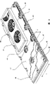
But Fig. 1 represents the signal oblique view of each layer of first example of the present invention's cutting luminous plaque;
Fig. 2 represents the cross section oblique view of the structure of luminous plaque second example of the present invention;
Fig. 3 represents the embodiment of luminous plaque of the present invention, and it has the specular structure of concave surface;
Fig. 4 represents another embodiment of luminous plaque of the present invention, and it has " spherical top ";
Fig. 5 represents the signal oblique view of another embodiment of luminous plaque of the present invention; And
Fig. 6 a and 6b represent other design of luminous plaque of the present invention.
Embodiment
In Fig. 1, expression conductive substrate 1.In illustrated example, it is designed to have the aluminium base of cooling fin 1a.Basic unit also can be by a plurality of layers of structure.If do not cause the cooling problem owing to LED density, it can form the plastic plate of metallizing layer so.If do not need or do not wish to have mechanical strength, it can also have conducting film to form.Then it can be placed on any object.
Being provided with the part opens 7 first dielectric film 2 and is placed in the basic unit 1.This film mainly comprises for example SiN, known polymer in SiC or the circuit board technology.It has for example thickness of 0.5-50 μ m.The rule mesh trellis configuration bit of conductor path 3 for example made of copper is on first film 2.Conductor path 3 separates with basic unit is electric by first dielectric film 2.
Four subelement 4a, 4b, 4c, 4d, 4e, 4f, 4g, 4h, 4k, 41,4m, 4n, 4o, the 4p of light-emitting diode chip for backlight unit (led chip or abbreviation LED) represent that in the drawings its dispersion is connected on basic unit 1 and the conductor path 3 also fastening by the conduction contact adhesive.Three LED4k, 41,4m are exceptions, and they contact in the bottom side by basic unit 1 and conductor path 3.Two LED that have three series connection separately of beginning of the subelement of left side expression among the figure.The 3rd subelement that the right side is represented comprises 6 LED 4d, 4e, 4f, 4g, 4h, the 4i of series connection.
Three subelements have led chip 4a, a 4d, 4n respectively, and it directly is arranged in first electrical contact surface on the chip downside with it, is placed in the basic unit 1, subsequently its LED as each subelement is discussed.The first led chip 4k of second subelement (4k, 41,4m) is arranged on the conductor path 3 and via opening 7 and is electrically connected in the basic unit 1 from its first electrical contact surface by pigtail splice 5.The one LED is connected on the conductor path 3 from its second electrical contact surface that is arranged in the chip upside by pigtail splice 5 separately. Other LED 4b, 4c, 4e, 4f, 4g, 4h, 4i, 41,4m, 4o, the 4p of series connection are connected on the conductor path 3 separately, this conductor path 3 be connected on the described top electrode of the corresponding led chip that is connected on the front by pigtail splice 5 or one of top electrode on.The top electrode of the last led chip 4c of series connection, 4i, 4m, 4p is by pigtail splice 5 contacts, and pigtail splice leads to cover layer, and this cover layer is not shown in the accompanying drawing for the purpose of improving general view.In the 4th sub-component, light-emitting diode 4n, 4o, 4p arrange with double distance.Electricity between the single conductor path 3 that is used for electric series LED 4n, 4o, 4p that causes thus interrupts connecting by the additional lead joint as conductor path contact device 8 under first kind of situation.Under second kind of situation, for the purpose of the voltage adaptation of whole subelement, conductor path 3 is by additional serial resistance 10 and suitable pigtail splice 5 bridge joints that are used to electrically contact.Another one resistance 9 is arranged in parallel with light-emitting diode 4o, and it is adaptive to form electric current for described light-emitting diode 4.
Illustrate by the following drawings with the main difference part of the embodiment that has described at the described embodiment of accompanying drawing.Omit the description of its same characteristic features.
Fig. 2 represents the signal oblique view of another embodiment structure of luminous plaque of the present invention.The circuit arrangement of this embodiment is different from the configuration of Fig. 1, wherein has only the subelement of the LED that has three series connection separately.Conductive covering layer 29 also part is illustrated among this figure.Also can see position extra play 30-32 thereon in addition.Conductive substrate 21 is as the parallel contact of series LED chip 24.Basic unit 21 comprises the cooling fin of the cooling of optimizing led chip 24.First dielectric film 22 with opening 27 of regular arrangement is placed in the basic unit 21.Can pass insulating barrier 22 by these opening 27 basic units 21 electrically contacts.The dispersion conductor path 23 that is used for led chip 24 series connection is placed on first insulating barrier 22.Second dielectric film 28 with opening is positioned on the conductor fin 23.First and second dielectric films form the insulating barrier that roughly is embedded with conductor path together.Simultaneously, according to manufacture method (placed layer under high or low temperature) and layer material, layer is evenly distributed on the circuit board and along the separate planes between film and constructs.Conductive covering layer 29 same parts are provided with opening, and are used from the parallel of subelement with basic unit 21 1 and contact.If make and for example form and the contacting of LED top electrode by transparent electrical conductors, also can be designed to not have opening on the conductive covering layer principle by pressurization.In this case, electric insulation layer preferably has roughly and the corresponding thickness of LED size.Replace transparent electrical conductors, cover layer also can comprise the thin electric conductor path that contacts top electrode, maybe can be connected on this conductor path.
Opening in the cover layer 29 can be designed so that it surrounds the contact surface of led chip 24 and each adjacent conductor path.Therefore, all right absolute standard manufacturing of cover layer, and any circuit of permission design LED.
When basic unit 21 with as effect between the cover layer 29 of contact surface the constant voltage that LED and circuit arrangement thereof determine being arranged, the LED subelement of series connection or luminous plaque and component block thereof carry out luminous.
Comprise that the thickness h of cooling off fin, electric insulation layer and tectal basic unit for example changes in the scope between 3 millimeters at about 0.5 millimeter and several millimeters.As mentioned above, basic unit also can carry out different designs, does not for example cool off fin.In this case, basic unit is corresponding thinner certainly.The value of the distance 1 between the LED can be preferably about 1.4 millimeters-10 millimeters.This LED density that causes luminous plaque to have is 1-49LED/cm
2Typical value is 2.5 millimeters for 1, and this LED density that causes luminous plaque to have is 16LED/cm
2LED density can reduce or increase at an easy rate, and wherein according to present LED, described value will approximately be 64LED/cm
2
Three extra play 30-32 are placed on the circuit arrangement of led chip 24.The first transparent extra play 30 is soft elasticity cover layers, for example consists essentially of the layer of silicone, and little reflection grain can add thereon.It is used for guaranteeing that light evenly distributes.First extra play 30 can be used for reducing the thermal stress that threatens led chip 24 in addition.
Second extra play 31 mainly is provided with secondary luminous pigment or pigment compound, for example luminous pigment.According to the mixing of color, select LED in this case, make it send blue light.By second hyaline layer, the light that LED sends partly converts the light of longer wavelength to.Final radiant light is the stack according to the different wave length of pigment composition.According to the color of LED and the quality and the characteristic of pigment, luminous plaque of the present invention and component block thereof can send the particularly light of any color.The stratiform configuration of extra play causes the even distribution of light in addition, and does not have edge effect.This packaged LED with prior art is opposite.Its housing can be provided with luminescent layer.But always cause anisotropic distribution of color, it is observed as annular.
The 3rd extra play 32 is transparent and is used as protective layer.It mainly comprises for example PMMA or PET.It also can comprise the optical element of direct light as required.Protective layer 32 is made by the material with certain anti-UV ability.
According to the structure of plate, the function of three extra play 30-32 also can realize by single, two or four or more a plurality of local hyaline layer.The function that should also be understood that the extra play realization is inessential for the function of plate, therefore also can completely or partially save extra play.
Fig. 3 represents another embodiment of luminous plaque of the present invention.Plate has a conductive substrate 41, first and second dielectric films 42,38, is used for the dispersion conductor path 43 and a conductive covering layer 49 of led chip 44 series connection, and the last led chip that will connect by pigtail splice 45 is connected with this cover layer.If desired, all layers have the opening 47 that is used to electrically contact.
Two extra plays 50,51 design as follows, make it have half hull shape recess 53 around led chip.Half hull shape recess preferably applies a reflector, for example has silver or aluminium, thereby recess is as concave mirror.The light that is sent by LED is limited on space (solid) angle of being determined by concave mirror.Recess 53 can be made soft hyaline layer 50,51 by embossing.In order to protect LED, insulating barrier and conductive layer and electrical connection and possible spill coating, recess can be filled by transparent thin-film material, for example silicone or PMMA.Also can only recess be combined in first extra play 50, for example homogenizing layer and/or contain in the layer of secondary luminous pigment.First extra play is also fully opaque and reflecting surface only is set.Protective clear layer 51 covers whole plate with protected mode, also has led chip and half hull shape recess 53 especially.
Fig. 4 represents another embodiment of the present invention.Basic unit is roughly identical with Fig. 3 with the layer configuration that comprises led circuit.For this embodiment, the extra play 60 with half hull shape recess 63 is set.Transparent material as silicon is filled in the recess 63, so that form calotte.This calotte is called " spherical tips " in luminescence technology.These half hull shape recess 64 will be sent and can be evenly distributed to by the light of the adjustment of protective layer 69 until on the outside whole half space by LED.
But the cutting luminous plaque according to one of Fig. 1 to 4 uses the not for example following manufacturing of encapsulation LED.
First electrical insulating film 2,22,42 with regular array of first opening 7,27,47 is placed in the basic unit 1,21,41.
Second electrical insulating film 28,48 is placed on first film and the conductor path, and described film has second opening, and this opening surrounds first opening and bigger than first opening, makes the conductor path of close each first opening partly be uncovered.
Second electrical insulating film to small part is covered by a conductive covering layer 29,49, wherein constructs in a conventional manner.
Second electrode of LED and conductor path or cover layer 29,49 is electrically connected, and the wherein following placement of LED, and second electrode of LED is following is connected on conductor path and the cover layer makes the operation subelement of the LED that can form series connection.
Subsequently, according to circumstances, installing has the performance that changes light and/or directional properties and/or as the extra play 30,31,32,50,51,60 of protective layer.
The embodiment that Fig. 5 represents also has the conductive substrate 71 and the electric insulation layer of arranging on it 72 that has (randomly) cooling fin.But this embodiment has particularity, and cover layer 79 and conductor path 73 in its middle level structure are arranged in the identical layer, and in manufacture process by the identical layer manufacturing.Here conductor path no longer divides come realization via electrical insulating film with " vertical " of luminescent layer by conductor path with tectal roughly electric insulation, but by the realization of coming of horizontal branch, the section of the insulating barrier 72 that wherein is uncovered is arranged between cover layer and the conductor path.For this reason, that cover layer has is big, be square (shape is inessential and select by any way as required) opening here substantially, and this opening surrounds a whole subelement separately.The one LED 74a of this subelement is contained in the opening 77 in the insulating barrier that is located immediately in the basic unit 71, and contact thus.The top electrode of the one LED is connected to conductor path by pigtail splice.The next LED 74b of subelement directly is arranged on the conductor path that directly contacts with the top electrode of a LED 74a.Three, the the 4th ... LED can be seated on the next separately conductor path by previous LED contact similarly.But the configuration shown in the figure is different from this.Here, the 3rd LED 74c is the same with the 4th electrode 74d is connected on the same conductor path reversedly." top " electrode of this LED is connected to by on the conductor path of the 2nd LED by the pigtail splice contact by pigtail splice equally.At the conductor path between second LED74b and the 3rd LED 74c so here mainly as the distance between these two LED of bridge joint.But, therefore preferably use this conductor owing to understanding oversize from second pigtail splice of guiding to the 4th LED and being affected easily.The electrode of the 4th LED 74d is connected on the cover layer 79 by pigtail splice, known to former embodiment.
From then on embodiment learns that once more the mode that can understand is easily used simple principle of the present invention like that, wherein conductor path be electrically connected surface insulation, luminous main body can contact this electrical connection surface.Circuit theory shown in the embodiment is the problem of selecting from a variety of possibilities.The contact that particularly can depart from an electrode of the light-emitting diode in the basic unit or on the conductor path connects, and this itself is favourable, and conductor path can be used as the device of bridge joint distance merely.Particular importance the LED on electrical insulating substrate, wherein two electrodes are positioned at top surface.In this case, all LED can directly be fastened on the position that basic unit is uncovered, and all contacts are undertaken by pigtail splice.
The plate of Fig. 5 has other characteristic.Because subelement is positioned at tectal opening fully, subelement separates with other subelements in clear and definite visible mode on the optics.This has simplified manufacturing for the user.For this reason, unless outside the device that accompanying drawing is described below using, under the situation that provides circuit board as the primary element of plate, subelement can only design with less flexibility.
As the situation of former embodiment, clear and definite once more here cover layer never needs to become shielding layer (convering layer).Cover layer but become the device of second conductive layer of parallel contact shoe unit simply.
Compared with former described plate, the plate of Fig. 5 is simpler on making.Electric insulation layer can be used as the regular array that single layer is placed in the basic unit and opening is set.Conductive layer is placed subsequently and is constructed, and makes to form the plane cover layer 79 with opening on the one hand, and in opening, the conductor layer of dispersion is partly as conductor path on the other hand.The luminous main body that illustrates in the former example is placed on basic unit or the conductor path.
The plate of Fig. 5 also can be provided with extra play certainly, and is as described above.
For the situation of every other plate, whole plate can have non-organic structure.In this case, insulating barrier is not the polymeric layer of normal conditions, and here for example is metal oxide layer.Here in the example of Miao Shuing, aluminium oxide is fit to, and it has the basic unit of aluminium.
The advantage that all non-organic structures have is that all material has favorable durability greater than 100 ℃ the time.Plate should be able to stand for example at least 120 ℃ temperature, even does not damage greater than 150 ℃.
Another embodiment of expression among Fig. 6 a and the 6b.Solved the other problems of initial period appearance by this embodiment.Luminous main body is subjected to better protection, and can improve optical efficiency.Because the structure of Fig. 6 a and 6b can also be selected extra play by any way.For example do not need to consider the difference of the thermal coefficient of expansion between basic unit and the extra play.Layer structure and circuit design according to example shown in Figure 5, but also can be different, and for example Fig. 1~4 are such.
Basic unit's (base plate) the 81st, metal, and for example comprise Heat Conduction Material as aluminium, copper etc.It works as first parallel conductor and heat abstractor in the mode of described case description.Basic unit 81 also can comprise the cooling fin here certainly.Basic unit 81 has a plurality of recess 91a, 91b, the shape that it has the part spherical shell and rotates parabolic intercepting.If the reflection of the inner surface of recess, recess is as reflector element.Flat zone on the recess downside is used for placing led chip.In not having the recess 91a of insulating barrier, the first led chip 84a separately of subelement directly is placed in the basic unit, and is similar with described embodiment.Other led chips 84b of each subelement is positioned at and has electric insulation layer 82 and have the recess that disperses conductor layer 83 that the position is used as the reflector thereon and also, so that contact with other led chips of series LED.Cover layer 89 design in the layer system of single layer in Fig. 5 explanation has the conductor path that disperses conductor layer 83, and it is particularly conducive to manufacturing, and this further specifies below.
Except the panel element of Fig. 6 a, the plate of Fig. 6 b has module extra play 93, and it is as cover layer.It is preferably selected to and makes it transparent as far as possible in visible scope, and becomes muddy under the UV radiation hardly.It can comprise plastics (for example Zhi Mi PET), glass or other transparent materials.
Cover layer 93 is the individual components that separate with support plate, and promptly it is not for example made with support plate or the luminous main body on it.It mechanically separates with support plate and luminous main body in article, and the transversely deforming of support plate and overlay or different thermal expansions can not cause acting on shear stress in luminous main body.
Optical element 93b can be set cover layer 93 so that the light that influence is produced by LED.In the accompanying drawings, these optical elements 93b is the Fresnel lens.But they also can comprise reflection (or mirror image) surface, can be used as the intercepting part of paraboloidal mirror or spherical mirror, and the mode that they can the Fresnel lens is divided into little section.Section with Fresnel lens can roughly be arranged along a plane (extra play plane).Light output with a certain required angle radiation simultaneously can increase by the once light of rectifying effect with respect to radiation.By outstanding convergence, efficient can approach
 Housing.The effective layer system 94 of optics that converts blue, purple or ultraviolet light to longer wavelength light wholly or in part can comprise single layer so that can be placed on the inboard of extra play 93.In addition, for example, filter for any too much blue light component as can be seen by a separates layers in layer system 94.Secondary luminous pigment (phosphor) and medium also can be used as fine particle and are present in the cover layer.
Cover layer is placed into (basic unit 91 that promptly has conduction and electric insulation layer) on the support plate with adhesive phase 92.In order accurately to locate cover layer in vertical direction, separating ball 92b can add wherein.Separating ball is incorporated into the form that wherein adhesive phase can film and obtains from the market, for example from 3M company.Selecting the thickness of adhesive phase 92 or the diameter of separating ball 92b, for example is 50 μ m at least, makes pigtail splice be uncovered layer 93 contact.Adhesive phase 92 is constructed, and makes it not cover the reflector space of (opening wide) recess 91a, 91b at least.
Back filler 95 with optics effective coverage of transparent material is also represented in the accompanying drawings.Can use this back filler so that guarantee to improve from the coupling output of led chip and the coupling input that improves transparent covering layer 93.For this reason, it advantageously has high index of refraction, for example higher than cover layer 93 refractive index.This back filler causes the machinery of led chip and the improvement of chemoproection and electrical connection (pigtail splice).According to the geometry of selecting; it can have permanent elasticity; so that prevent to act on the shear stress (wherein being positioned at LED the influence that is not subjected to shear stress because selected shape is protected greatly of recess 91a, 91b) on the LED fully even the material of back filler 95 is not that elasticity also is like this.
In the accompanying drawings, also represent how according to circumstances to provide the structure of cover layer 93.These structure example are as being used as theoretical open position or theoretical striping, also as the decoupling zero position of mechanical stress.
The optional member of Fig. 6 b plate be add, local positioning, transparent and opaque conductor path 97, it extends at the downside of cover layer 93, and makes the LED of series connection extend and pass through this cover layer as the second parallel conductor layer on cover layer 89.In the configuration of Fig. 5, these extra conductor paths extend between the single subelement in the opening of cover layer 79.Reference numeral 98 expression lower conductor paths 83 for example adopt electroconductive binder to the electrical connection of extra conductor path 97.
Cover layer also can comprise a plurality of sublayers (not shown) of identical or different material.For example in the gap between two sublayers, can have the film that has the secondary luminous pigment.Cover layer also can directly comprise the secondary luminous pigment certainly, and wherein this modification is specially adapted to plastics covering.
The advantage of support plate with recess is as follows: under existing thickness, increase rigidity by recess.Increase the efficient of light as the recess of paraboloidal mirror at least roughly.Overlay can be used as the plane component (modular structure) that separates with support plate, the operation that it can add (focusing, filtration etc.).Separate by machinery, prevent that LED is subjected to because the influence of the shear stress that thermal expansion causes.Allow extra play to be present on the inboard if overlay separates with support plate, and be not subjected to any mechanical wear, therefore do not need wear-resisting.And the last because shape of recess, also having increased should the surface, improves then heat is scattered.
Can be replaced by metal film or glass-film if the plate of Fig. 6 b, has the adhesive phase 92 of separating ball 92b with all non-organic structure manufacturings, it is welded on (for example with scolder or glass solder) on upside and the downside, or fastening to engage connection.
But have the separated support plate of cover layer on the principle and also can not have recess.But in this case, by the distance between fixing these two elements of distance piece must be significantly greater than the thickness of luminous main body and the height summation of leaving the pigtail splice that its guides, in this case, significantly greater than about 250 μ m+200 μ m.This distance is too big for many application.
According to the manufacturing of the support plate of the plate of one of Fig. 6 a and 6b realizing with Fig. 1~similar mode of 5 support plates, wherein also will be in conjunction with other recess.The grinding steel ball forms flat zone.Then use the deep-draw or the embossing shape that occur subsequently to be out of shape basic unit.Under the initial condition or because the ductility of institute's materials used and also can in the basic unit that does not have under the further situation of difficult in coating, carrying out in the distortion in the basic unit.LED produces the more direct focusing of light and can realize at the deep-draw mould, so that in conjunction with the recess with parabolic shape rather than ball cap shape profile.
Form printed circuit board (PCB) for example and comprise basic unit 1,21,41,71,81 as the support plate of the parts of luminous plaque, it has conductive surface, and have the electric insulation layer that is placed on it and first opening regular array and with the regular grid of the conductive path of basic unit electric insulation, and with the cover layer that contacts electric insulation and conductor path, and having the regular array of second opening, second opening surrounds first opening and bigger than first opening.At last, support plate can be for example designs according to the mode of the description of one of described luminous plaque.
Through above discussion, in fact always can be susceptible to luminous body design is LED.In the viewpoint of prior art, LED is the most suitable luminous main body, but really in other luminous main bodys that can obtain having in the future similar functions.The present invention will develop and according to the luminous main body of existing or new technology particularly including this.
Claims (21)
1. luminous plaque with a support plate, described support plate comprises
Basic unit (1,21,41) with a conductive surface;
Be placed on it and have the electric insulation layer of the regular array of first opening;
With latticed mode regular arrangement and with the conductor path of basic unit's electric insulation;
Wherein first aperture arrangement is on the crosspoint of conductor path grid, and conductor path interrupts at these places, crosspoints;
And with the conductive layer (29,49,79,89) of basic unit and conductor path electric insulation, it has the regular array of second opening, second opening surrounds first opening and bigger than first opening;
Described luminous plaque has minimum subelement in parallel, this subelement has the luminous main body (4a, 4b, 4c, 4d, 4e, 4f, 4g, 4h, 4i, 4k, 4l, 4m, 4n, 4o, 4p, 24,44,74a, 74b, 74c, 74d, 84a, 84b) of at least two series connection in each case, this luminous main body can be handled with electric power, and be connected on the support plate, wherein the luminous main body of subelement in series is electrically connected by conductor path;
Wherein basic unit and conductive layer walk abreast with connecting the surface so that with subelement and electrically contact;
And wherein by cutting basic unit, luminous plaque is separated into the component block that itself can operate, and it has the size of minimum subelement at least.
2. luminous plaque as claimed in claim 1 is characterized in that, several at least luminous main bodys (4b, 4c, 4e, 4f, 4g, 4h, 4i, 4k, 4l, 4m, 4n, 4o, 4p, 74b, 74c, 74d, 84b) are located immediately on the conductor path and are in contact with it.
3. luminous plaque as claimed in claim 1 or 2, it is characterized in that, each luminous main body comprises first and second electrodes, first electrode of each the first luminous main body (4a, 4d, 4k, 4n, 74a, 84a) in each subelement is contacted by basic unit (1,21,41,71,81), second electrode of the last luminous main body of each of each subelement (4c, 4i, 4m, 4p) is connected on the conductive layer (29,49,79,89) by contact device (5,25,45), and the electrode of therebetween luminous main body interconnects by conductor path.
4. luminous plaque as claimed in claim 3, it is characterized in that, opening (7 in the insulating barrier, 27,47,77) first of Nei the subelement luminous main body (4a, 4d, 4k, 4n, 74a, 84a) be connected basic unit (1,21,41,71,91) on, and contact thus by first electrode, luminous main body (the 4b of other of subelement wherein, 4c, 4e, 4f, 4g, 4h, 4i, 4l, 4m, 4o, 4p) be connected conductor path (3,23,43) go up and contact thus by first electrode, the last luminous main body (4c of subelement wherein, 4i, 4m, second electrode 4p) is by conductive layer (29,49) contact, and wherein second electrode of the luminous main body of residue of subelement can contact with the conductor path of the next luminous main body separately of subelement.
5. luminous plaque as claimed in claim 4, it is characterized in that, for being electrically connected in series of the luminous main body of described subelement, no matter be arranged in insulating barrier (2,22,42,72,82) Nei first opening (7,27,47,77) predetermined cell between distance and also no matter conductor path (3,23,43,73,83) the predetermined in view of the above length that limits, described luminous main body is with uneven pitch arrangement, wherein the luminous main body of at least one subelement is not contained in insulating barrier (2,22,42,72,82) each first opening (7,27,47,77) locate, and only be contained in each first opening (7,27,47,77) next opening part, i.e. second opening part or the 3rd opening part, perhaps have another order, the wherein conductor path (3 that is being used for being electrically connected in series between them thus of changing distance, 23,43) electricity between interrupts by conductor path contact device (8) bridge joint.
6. as the described luminous plaque in one of claim 1 or 2, it is characterized in that, the electrically insulated from one another of basic unit, conductor path and conductive layer realizes by an electric insulation layer (2,22,42,72,82), and conductor path (3,23,43,73,93) extends in the inboard of the opening of electric insulation layer at least in part.
7. luminous plaque as claimed in claim 6, it is characterized in that, electric insulation layer is formed by first and second electrical insulating films, wherein conductor path (3,23,43,73,83) to small part is positioned between described first electrical insulating film (2,22,42,72,82) and described second electrical insulating film (28,48).
8. luminous plaque as claimed in claim 1 or 2, it is characterized in that, additional electrical component (9,10) is in parallel or be connected in series on the single or luminous main body in groups (4a, 4b, 4c, 4d, 4e, 4f, 4g, 4h, 4i, 4k, 4l, 4m, 4n, 4o, 4p, 24,44) of whole subelement of electricity series connection.
9. luminous plaque as claimed in claim 1 or 2 is characterized in that, basic unit (1,21,41) comprises radiator structure, or is placed on the mechanical carrier that has radiator structure.
10. luminous plaque as claimed in claim 1 or 2 is characterized in that luminous main body is LED, and wherein several at least LED are blue light or purple light or ultraviolet leds.
11. luminous plaque as claimed in claim 1 or 2 is characterized in that, at least one to small part be transparent extra play (30,32,50,51,93,94), be arranged to luminous main body between basic unit and extra play, or be cast in the extra play.
12. luminous plaque as claimed in claim 11 is characterized in that, extra play or at least one extra play are transparent, and reflection grain and/or optical element or structure (53,63,64,93b) are set so that guiding and/or distribute light.
13. luminous plaque as claimed in claim 11 is characterized in that, at least one extra play (31,50,60,94) comprises the secondary luminous pigment.
14. luminous plaque as claimed in claim 13 is characterized in that, the extra play with secondary luminous pigment is flat and covers a plurality of luminous main bodys.
15. as claim 13 or 14 described luminous plaques, it is characterized in that extra play (93) is connected on the support plate as cover layer, support plate is loaded with luminous main body, this extra play and luminous main body are mechanically separated, escapement (92b) is wherein arranged between support plate and cover layer.
16. luminous plaque as claimed in claim 15 is characterized in that, secondary luminescent film (94) is placed on forming between the tectal layer towards a side of luminous main body or at least two of extra play (93), and perhaps extra play (93) comprises the secondary luminous pigment.
17. luminous plaque as claimed in claim 15 is characterized in that, the cover layer in the luminous main body upper area comprises optical element (93b), or has the structure of reflecting surface, makes directional effect increase.
18. luminous plaque is characterized in that as claimed in claim 1 or 2, basic unit comprises recess (91a) array of a rule, and wherein several at least luminous main bodys are contained in the recess.
19. luminous plaque as claimed in claim 18 is characterized in that, the recess setting is as the coating in reflector, and they form global shell or have the paraboloidal shape in flat zone.
20. luminous plaque as claimed in claim 1 or 2 is characterized in that, described luminous plaque does not have organic material.
21. support plate, parts as the described luminous plaque of one of claim 1 to 20, it comprises the basic unit (1 with a conductive surface, 21,41) and have an electric insulation layer that is arranged in the basic unit, and the regular array of first opening and rule mesh trellis arrange and with the conductor path of basic unit's electric insulation, wherein first aperture arrangement is interrupted at these places, crosspoint at the place, crosspoint and the conductor path of conductor path grid, and with the conductive layer of basic unit and conductor path electric insulation, this conductive layer has the regular array of second opening, and second opening surrounds first opening and bigger than first opening.
Applications Claiming Priority (3)
| Application Number | Priority Date | Filing Date | Title |
|---|---|---|---|
| CH17002001 | 2001-09-13 | ||
| CH1700/2001 | 2001-09-13 | ||
| CH1700/01 | 2001-09-13 |
Publications (2)
| Publication Number | Publication Date |
|---|---|
| CN1586006A CN1586006A (en) | 2005-02-23 |
| CN100477210C true CN100477210C (en) | 2009-04-08 |
Family
ID=4565955
Family Applications (1)
| Application Number | Title | Priority Date | Filing Date |
|---|---|---|---|
| CNB028223934A Expired - Fee Related CN100477210C (en) | 2001-09-13 | 2002-06-24 | Led-luminous panel and carrier plate |
Country Status (7)
| Country | Link |
|---|---|
| US (1) | US7055987B2 (en) |
| EP (1) | EP1451872B1 (en) |
| JP (1) | JP2005502214A (en) |
| CN (1) | CN100477210C (en) |
| AT (1) | ATE356532T1 (en) |
| DE (1) | DE50209685D1 (en) |
| WO (1) | WO2003023857A2 (en) |
Families Citing this family (118)
| Publication number | Priority date | Publication date | Assignee | Title |
|---|---|---|---|---|
| CN1245586C (en) * | 2000-07-07 | 2006-03-15 | 宇宙设备公司 | Method of producing plants, plant cultivating device, and light-emitting panel |
| US7279718B2 (en) | 2002-01-28 | 2007-10-09 | Philips Lumileds Lighting Company, Llc | LED including photonic crystal structure |
| AU2003233248B2 (en) * | 2002-06-14 | 2006-11-09 | Lednium Technology Pty Limited | A lamp and method of producing a lamp |
| US10340424B2 (en) | 2002-08-30 | 2019-07-02 | GE Lighting Solutions, LLC | Light emitting diode component |
| CN100383573C (en) * | 2002-12-02 | 2008-04-23 | 3M创新有限公司 | Illumination system using a plurality of light sources |
| WO2004088761A1 (en) * | 2003-04-02 | 2004-10-14 | Lucea Ag | Light-emitting panel |
| EP1465256A1 (en) * | 2003-04-03 | 2004-10-06 | Micro Photonics Technology | A method of producing a light source and a light source assembly |
| EP1467415B1 (en) * | 2003-04-08 | 2019-06-12 | Lumileds Holding B.V. | Improved LED efficiency using photonic crystal structure |
| US20070001177A1 (en) * | 2003-05-08 | 2007-01-04 | Koninklijke Philips Electronics N.V. | Integrated light-emitting diode system |
| EP1623153A1 (en) * | 2003-05-15 | 2006-02-08 | Lucea AG | Light source |
| US7329024B2 (en) * | 2003-09-22 | 2008-02-12 | Permlight Products, Inc. | Lighting apparatus |
| US7012279B2 (en) | 2003-10-21 | 2006-03-14 | Lumileds Lighting U.S., Llc | Photonic crystal light emitting device |
| US20050116235A1 (en) * | 2003-12-02 | 2005-06-02 | Schultz John C. | Illumination assembly |
| US20050205883A1 (en) | 2004-03-19 | 2005-09-22 | Wierer Jonathan J Jr | Photonic crystal light emitting device |
| DE102004019137A1 (en) * | 2004-04-16 | 2005-11-17 | Trilux-Lenze Gmbh + Co Kg | Leuchtenfeld |
| EP1735845A2 (en) * | 2004-04-16 | 2006-12-27 | Lucea AG | Housing for led chip and light source |
| WO2005100016A2 (en) * | 2004-04-16 | 2005-10-27 | Lucea Ag | Light-emitting panel and optically effective foil |
| JP2005310892A (en) * | 2004-04-19 | 2005-11-04 | Nippon Seiki Co Ltd | Light emitting device |
| US8188503B2 (en) * | 2004-05-10 | 2012-05-29 | Permlight Products, Inc. | Cuttable illuminated panel |
| US7442964B2 (en) | 2004-08-04 | 2008-10-28 | Philips Lumileds Lighting Company, Llc | Photonic crystal light emitting device with multiple lattices |
| TWI255377B (en) * | 2004-11-05 | 2006-05-21 | Au Optronics Corp | Backlight module |
| CN100483024C (en) * | 2004-11-09 | 2009-04-29 | 李学霖 | Heat radiation structure of LED lamp |
| US7270446B2 (en) * | 2005-05-09 | 2007-09-18 | Lighthouse Technology Co., Ltd | Light module with combined heat transferring plate and heat transferring pipes |
| US7595453B2 (en) * | 2005-05-24 | 2009-09-29 | M/A-Com Technology Solutions Holdings, Inc. | Surface mount package |
| US8163575B2 (en) | 2005-06-17 | 2012-04-24 | Philips Lumileds Lighting Company Llc | Grown photonic crystals in semiconductor light emitting devices |
| KR20070000835A (en) * | 2005-06-28 | 2007-01-03 | 엘지.필립스 엘시디 주식회사 | Backlight unit |
| US8163580B2 (en) * | 2005-08-10 | 2012-04-24 | Philips Lumileds Lighting Company Llc | Multiple die LED and lens optical system |
| CN100365485C (en) * | 2005-08-31 | 2008-01-30 | 友达光电股份有限公司 | Direct type backlight module |
| JP4483757B2 (en) * | 2005-09-30 | 2010-06-16 | セイコーエプソン株式会社 | Organic EL device and optical device |
| US20070081339A1 (en) * | 2005-10-07 | 2007-04-12 | Chung Huai-Ku | LED light source module with high efficiency heat dissipation |
| US8044412B2 (en) | 2006-01-20 | 2011-10-25 | Taiwan Semiconductor Manufacturing Company, Ltd | Package for a light emitting element |
| KR100649327B1 (en) * | 2006-03-09 | 2006-11-28 | 조경준 | A lamp using public telephone booth |
| DE202006004774U1 (en) * | 2006-03-25 | 2007-07-26 | Mücke, Daniel | Display device, in particular LED display |
| KR100755615B1 (en) * | 2006-04-14 | 2007-09-06 | 삼성전기주식회사 | Backlight for liquid crystal display comprising light emitting diode |
| US9335006B2 (en) * | 2006-04-18 | 2016-05-10 | Cree, Inc. | Saturated yellow phosphor converted LED and blue converted red LED |
| JP4978053B2 (en) * | 2006-05-02 | 2012-07-18 | 日亜化学工業株式会社 | Light emitting device and lighting device |
| WO2007147278A2 (en) * | 2006-06-21 | 2007-12-27 | Gerhard Staufert | Led light source and method |
| KR100796522B1 (en) * | 2006-09-05 | 2008-01-21 | 삼성전기주식회사 | Manufacturing method of imbedded pcb |
| DE102006046301A1 (en) * | 2006-09-29 | 2008-04-03 | Osram Opto Semiconductors Gmbh | Optical element, has base body, which contains basic material, and filling body, which contains filling material, where filling body adheres to base body |
| US7952262B2 (en) * | 2006-09-30 | 2011-05-31 | Ruud Lighting, Inc. | Modular LED unit incorporating interconnected heat sinks configured to mount and hold adjacent LED modules |
| US9243794B2 (en) | 2006-09-30 | 2016-01-26 | Cree, Inc. | LED light fixture with fluid flow to and from the heat sink |
| US9028087B2 (en) | 2006-09-30 | 2015-05-12 | Cree, Inc. | LED light fixture |
| US7686469B2 (en) | 2006-09-30 | 2010-03-30 | Ruud Lighting, Inc. | LED lighting fixture |
| US20090086491A1 (en) | 2007-09-28 | 2009-04-02 | Ruud Lighting, Inc. | Aerodynamic LED Floodlight Fixture |
| US10295147B2 (en) * | 2006-11-09 | 2019-05-21 | Cree, Inc. | LED array and method for fabricating same |
| US7897980B2 (en) * | 2006-11-09 | 2011-03-01 | Cree, Inc. | Expandable LED array interconnect |
| US20080123340A1 (en) * | 2006-11-27 | 2008-05-29 | Mcclellan Thomas | Light device having LED illumination and electronic circuit board in an enclosure |
| KR20080057881A (en) * | 2006-12-21 | 2008-06-25 | 엘지전자 주식회사 | Printed circuit board, light emitting apparatus having the same and method for manufacturing thereof |
| DE102006061941A1 (en) * | 2006-12-29 | 2008-07-03 | Osram Opto Semiconductors Gmbh | Optoelectronic arrangement, has power light emitting diode, where radiation is emitted from power light emitting diode, and adjusting light emitting diode, where another radiation is emitted from adjusting light emitting diode |
| EP1998101B2 (en) * | 2007-05-30 | 2019-09-25 | OSRAM GmbH | Lighting device |
| JP4533405B2 (en) * | 2007-05-31 | 2010-09-01 | 株式会社 日立ディスプレイズ | LIGHTING DEVICE AND LIQUID CRYSTAL DISPLAY DEVICE USING THE LIGHTING DEVICE |
| JP4474441B2 (en) * | 2007-06-29 | 2010-06-02 | 株式会社沖データ | Light emitting panel, display device, and light source device |
| TW200904316A (en) * | 2007-07-13 | 2009-01-16 | Kai-Yu Lin | Heat-dissipation structure of luminous device |
| US8033684B2 (en) * | 2007-08-31 | 2011-10-11 | The Boeing Company | Starry sky lighting panels |
| US7857484B2 (en) * | 2007-08-31 | 2010-12-28 | The Boeing Company | Lighting panels including embedded illumination devices and methods of making such panels |
| US7994524B1 (en) | 2007-09-12 | 2011-08-09 | David Yaunien Chung | Vertically structured LED array light source |
| DE102007046348A1 (en) * | 2007-09-27 | 2009-04-02 | Osram Opto Semiconductors Gmbh | Radiation-emitting device with glass cover and method for its production |
| WO2009061352A1 (en) * | 2007-11-08 | 2009-05-14 | Innovations In Optics, Inc | Led illumination system |
| US9135837B2 (en) * | 2007-11-16 | 2015-09-15 | Intellectual Discovery Co., Ltd. | Illumination assembly having multiple reflective cavities each with a single emitter |
| DE102008011153B4 (en) * | 2007-11-27 | 2023-02-02 | OSRAM Opto Semiconductors Gesellschaft mit beschränkter Haftung | Process for producing an arrangement with at least two light-emitting semiconductor components |
| US20110095310A1 (en) | 2008-03-26 | 2011-04-28 | Shimane Prefectural Government | Semiconductor light emitting module and method of manufacturing the same |
| US8183581B2 (en) | 2008-05-13 | 2012-05-22 | Siemens Aktiengesellschsft | LED arrangement |
| US7845829B2 (en) * | 2008-05-20 | 2010-12-07 | Abl Ip Holding Llc | Enclosures for LED circuit boards |
| CN101608774B (en) * | 2008-06-20 | 2011-03-30 | 富准精密工业(深圳)有限公司 | Light-emitting diode illumination device and manufacturing method thereof |
| KR101448153B1 (en) * | 2008-06-25 | 2014-10-08 | 삼성전자주식회사 | Multi-chip package for LED chip and multi-chip package LED device |
| WO2010018682A1 (en) | 2008-08-11 | 2010-02-18 | ローム株式会社 | Lighting device |
| EP2311104B1 (en) * | 2008-08-11 | 2018-03-28 | OSRAM GmbH | Conversion led |
| US8132935B2 (en) * | 2008-09-01 | 2012-03-13 | Samsung Led Co., Ltd. | Light emitting module |
| WO2010044499A1 (en) * | 2008-10-17 | 2010-04-22 | Ki-Geon Lee | Radiating heat apparatus for circuit board, led lamp having thereof, lighting apparatus euipped with led lamp thereon |
| TW201020460A (en) * | 2008-11-26 | 2010-06-01 | Ling Chyuan Fa Ing Yonq Ltd | Heat-dissipation structure of LED |
| CN101749686B (en) * | 2008-12-03 | 2012-03-14 | 富准精密工业(深圳)有限公司 | Light emitting diode lamp |
| US20100226139A1 (en) | 2008-12-05 | 2010-09-09 | Permlight Products, Inc. | Led-based light engine |
| JP5146356B2 (en) * | 2009-02-24 | 2013-02-20 | 豊田合成株式会社 | Light emitting device and manufacturing method thereof |
| US20100225215A1 (en) * | 2009-03-03 | 2010-09-09 | Han-Ming Lee | Multi-chip cup semi-conductor lamp |
| CH701423B1 (en) * | 2009-07-10 | 2015-02-13 | Christoph Liebetrau Ur Brain Gmbh | High-power LED flat light. |
| WO2011019856A1 (en) * | 2009-08-12 | 2011-02-17 | Edward Stoneham | Versatile sealed led lamp |
| US8684556B2 (en) * | 2009-09-30 | 2014-04-01 | Cree, Inc. | Light emitting diode (LED) lighting systems including low absorption, controlled reflectance and diffusion layers |
| US8360604B2 (en) * | 2009-09-30 | 2013-01-29 | Cree, Inc. | Light emitting diode (LED) lighting systems including low absorption, controlled reflectance enclosures |
| US8593040B2 (en) | 2009-10-02 | 2013-11-26 | Ge Lighting Solutions Llc | LED lamp with surface area enhancing fins |
| US8511851B2 (en) * | 2009-12-21 | 2013-08-20 | Cree, Inc. | High CRI adjustable color temperature lighting devices |
| US8672516B2 (en) * | 2010-09-30 | 2014-03-18 | GE Lighting Solutions, LLC | Lightweight heat sinks and LED lamps employing same |
| US10024510B2 (en) * | 2010-10-26 | 2018-07-17 | Steven G. Hammond | Flexible light emitting diode lighting process and assembly |
| FR2970060B1 (en) * | 2010-11-08 | 2014-11-21 | Valeo Vision | DEVICE FOR LIGHTING AND / OR SIGNALING A MOTOR VEHICLE |
| USD707192S1 (en) | 2010-11-18 | 2014-06-17 | Cree, Inc. | Light emitting device |
| US8564000B2 (en) | 2010-11-22 | 2013-10-22 | Cree, Inc. | Light emitting devices for light emitting diodes (LEDs) |
| USD721339S1 (en) | 2010-12-03 | 2015-01-20 | Cree, Inc. | Light emitter device |
| USD712850S1 (en) | 2010-11-18 | 2014-09-09 | Cree, Inc. | Light emitter device |
| US9490235B2 (en) | 2010-11-22 | 2016-11-08 | Cree, Inc. | Light emitting devices, systems, and methods |
| US9000470B2 (en) | 2010-11-22 | 2015-04-07 | Cree, Inc. | Light emitter devices |
| US8624271B2 (en) | 2010-11-22 | 2014-01-07 | Cree, Inc. | Light emitting devices |
| US8575639B2 (en) | 2011-02-16 | 2013-11-05 | Cree, Inc. | Light emitting devices for light emitting diodes (LEDs) |
| US9300062B2 (en) | 2010-11-22 | 2016-03-29 | Cree, Inc. | Attachment devices and methods for light emitting devices |
| USD706231S1 (en) | 2010-12-03 | 2014-06-03 | Cree, Inc. | Light emitting device |
| WO2012080911A1 (en) * | 2010-12-16 | 2012-06-21 | Koninklijke Philips Electronics N.V. | Led-based assembly |
| US9786811B2 (en) | 2011-02-04 | 2017-10-10 | Cree, Inc. | Tilted emission LED array |
| US8809880B2 (en) | 2011-02-16 | 2014-08-19 | Cree, Inc. | Light emitting diode (LED) chips and devices for providing failure mitigation in LED arrays |
| US8729589B2 (en) | 2011-02-16 | 2014-05-20 | Cree, Inc. | High voltage array light emitting diode (LED) devices and fixtures |
| USD702653S1 (en) | 2011-10-26 | 2014-04-15 | Cree, Inc. | Light emitting device component |
| US8455908B2 (en) | 2011-02-16 | 2013-06-04 | Cree, Inc. | Light emitting devices |
| WO2013001430A1 (en) | 2011-06-30 | 2013-01-03 | Koninklijke Philips Electronics N.V. | Led-based embedded lighting device |
| USD700584S1 (en) | 2011-07-06 | 2014-03-04 | Cree, Inc. | LED component |
| US10842016B2 (en) | 2011-07-06 | 2020-11-17 | Cree, Inc. | Compact optically efficient solid state light source with integrated thermal management |
| US20130048885A1 (en) * | 2011-08-31 | 2013-02-28 | Phoseon Technology, Inc. | Lighting module having a common terminal |
| USD705181S1 (en) | 2011-10-26 | 2014-05-20 | Cree, Inc. | Light emitting device component |
| US10134961B2 (en) | 2012-03-30 | 2018-11-20 | Cree, Inc. | Submount based surface mount device (SMD) light emitter components and methods |
| US9735198B2 (en) | 2012-03-30 | 2017-08-15 | Cree, Inc. | Substrate based light emitter devices, components, and related methods |
| US9500355B2 (en) | 2012-05-04 | 2016-11-22 | GE Lighting Solutions, LLC | Lamp with light emitting elements surrounding active cooling device |
| JP2014036107A (en) * | 2012-08-08 | 2014-02-24 | Toshiba Lighting & Technology Corp | Light-emitting module and luminaire |
| US20140048824A1 (en) * | 2012-08-15 | 2014-02-20 | Epistar Corporation | Light-emitting device |
| DE102012109819A1 (en) * | 2012-10-15 | 2014-04-17 | Bruck Gmbh & Co Kg | Lighting system for use as ceiling light, has lamp body, heat sink, lighting unit and reflector, where lamp body is made of transparent material and is provided with light emitting surface and rear end surface |
| USD740453S1 (en) | 2013-06-27 | 2015-10-06 | Cree, Inc. | Light emitter unit |
| USD739565S1 (en) | 2013-06-27 | 2015-09-22 | Cree, Inc. | Light emitter unit |
| US9865185B2 (en) * | 2013-08-15 | 2018-01-09 | Bitro Group, Inc. | LED matrix lighting device |
| CN104009147A (en) * | 2014-06-12 | 2014-08-27 | 上海虔敬节能环保科技有限公司 | LED multifunctional packaging structure and packaging technology thereof |
| USD823492S1 (en) | 2016-10-04 | 2018-07-17 | Cree, Inc. | Light emitting device |
| RU174281U1 (en) * | 2016-11-22 | 2017-10-09 | Егор Евгеньевич Нилов | LIGHTING DEVICE |
| US10690302B1 (en) | 2019-02-27 | 2020-06-23 | BrooksCo, LLC | Flexible and cuttable LED sheet |
| US11460173B1 (en) | 2021-01-05 | 2022-10-04 | BrooksCo, LLC | LED backlight system and mounting system |
Family Cites Families (13)
| Publication number | Priority date | Publication date | Assignee | Title |
|---|---|---|---|---|
| JPS58194383A (en) * | 1982-05-07 | 1983-11-12 | Sumitomo Electric Ind Ltd | Continuously assembled light-emitting diode |
| JPS61145877A (en) * | 1984-12-19 | 1986-07-03 | Mitsubishi Electric Corp | Led array head |
| JPS6486573A (en) * | 1987-07-17 | 1989-03-31 | Oshima Denki Co | Light emitting device |
| US4935665A (en) | 1987-12-24 | 1990-06-19 | Mitsubishi Cable Industries Ltd. | Light emitting diode lamp |
| US5119174A (en) * | 1990-10-26 | 1992-06-02 | Chen Der Jong | Light emitting diode display with PCB base |
| US5278432A (en) * | 1992-08-27 | 1994-01-11 | Quantam Devices, Inc. | Apparatus for providing radiant energy |
| JPH088463A (en) * | 1994-06-21 | 1996-01-12 | Sharp Corp | Thin type led dot matrix unit |
| US5698866A (en) * | 1994-09-19 | 1997-12-16 | Pdt Systems, Inc. | Uniform illuminator for phototherapy |
| US5785418A (en) * | 1996-06-27 | 1998-07-28 | Hochstein; Peter A. | Thermally protected LED array |
| CH689339A5 (en) * | 1998-02-12 | 1999-02-26 | Staufert Gerhard | LED illumination panel |
| SE518269C2 (en) * | 1998-04-30 | 2002-09-17 | Ericsson Telefon Ab L M | PCBs and method for processing PCBs |
| DE19926746B4 (en) * | 1999-06-11 | 2005-06-16 | Osram Opto Semiconductors Gmbh | Multiple arrangement of PCBs equipped with LEDs and connectors for connecting printed circuit boards |
| US6504301B1 (en) * | 1999-09-03 | 2003-01-07 | Lumileds Lighting, U.S., Llc | Non-incandescent lightbulb package using light emitting diodes |
-
2002
- 2002-06-24 WO PCT/CH2002/000339 patent/WO2003023857A2/en active IP Right Grant
- 2002-06-24 EP EP02740176A patent/EP1451872B1/en not_active Expired - Lifetime
- 2002-06-24 DE DE50209685T patent/DE50209685D1/en not_active Expired - Fee Related
- 2002-06-24 AT AT02740176T patent/ATE356532T1/en not_active IP Right Cessation
- 2002-06-24 JP JP2003527799A patent/JP2005502214A/en active Pending
- 2002-06-24 US US10/489,116 patent/US7055987B2/en not_active Expired - Fee Related
- 2002-06-24 CN CNB028223934A patent/CN100477210C/en not_active Expired - Fee Related
Also Published As
| Publication number | Publication date |
|---|---|
| EP1451872A2 (en) | 2004-09-01 |
| EP1451872B1 (en) | 2007-03-07 |
| ATE356532T1 (en) | 2007-03-15 |
| WO2003023857A3 (en) | 2004-06-03 |
| WO2003023857A2 (en) | 2003-03-20 |
| JP2005502214A (en) | 2005-01-20 |
| US20040233671A1 (en) | 2004-11-25 |
| US7055987B2 (en) | 2006-06-06 |
| CN1586006A (en) | 2005-02-23 |
| DE50209685D1 (en) | 2007-04-19 |
Similar Documents
| Publication | Publication Date | Title |
|---|---|---|
| CN100477210C (en) | Led-luminous panel and carrier plate | |
| US11101410B2 (en) | LED systems, apparatuses, and methods | |
| US7932523B2 (en) | LED lamp for light source of lighting device | |
| CN103477456B (en) | Light-emitting device with wavelength conversion layer | |
| CN100414698C (en) | Power surface mount light emitting die package | |
| EP1815534B1 (en) | Composite LED modules | |
| US10453827B1 (en) | LED apparatuses and methods | |
| CN100502064C (en) | Package for light emitting device | |
| CN102214774B (en) | Light emitting device package and light unit having the same | |
| CN100530579C (en) | Method for manufacture of transparent devices having light emitting diodes (LED) | |
| CN101050846B (en) | Method for producing flexible light source and flexible base board and flexible solid state light source | |
| KR101662038B1 (en) | chip package | |
| CN103022024A (en) | Solid state lighting component | |
| CN103210490A (en) | Solid state light sheet or strip for general illumination | |
| CN103199170B (en) | System level photoelectric structure and preparation method thereof | |
| CN102272923A (en) | solid state lighting component | |
| CN103443939A (en) | Light emitting diode (LED) arrays including direct die attach and related assemblies | |
| EP3776674A1 (en) | Led apparatuses, and method | |
| CN102185089A (en) | Light emitting apparatus and lighting system | |
| CN102290409A (en) | Light-emitting apparatus | |
| CN104205371A (en) | LED module and production method therefor, lighting device | |
| WO2015117273A1 (en) | Smart pixel surface mount device package | |
| CN102544341A (en) | Light emitting device and illumination apparatus using same | |
| CN103075678A (en) | Light source module and lighting apparatus having the same | |
| CN106206905A (en) | Package structure for LED |
Legal Events
| Date | Code | Title | Description |
|---|---|---|---|
| C06 | Publication | ||
| PB01 | Publication | ||
| C10 | Entry into substantive examination | ||
| SE01 | Entry into force of request for substantive examination | ||
| C14 | Grant of patent or utility model | ||
| GR01 | Patent grant | ||
| C17 | Cessation of patent right | ||
| CF01 | Termination of patent right due to non-payment of annual fee |
Granted publication date: 20090408 Termination date: 20100624 |