The application is that the name that entered country's stage on March 20th, 1998 is called the dividing an application of International Patent Application PCT/US96/12243 (Chinese application number 96197085.5) of " acoustic correction apparatus ".
Summary of the invention
Although prior art is made so many contribution, still there is a kind of like this acoustic image calibration equipment demand, this calibration equipment can easily adapt to various Sound reproducing environment with distortion space characteristics.Also have a kind of like this acoustic image corrective system demand in addition, this acoustic image corrective system harmony image intensifying equipment co-operation strengthens so that the stereo sound image after proofreading and correct is carried out the space.
Acoustic correction apparatus disclosed herein, and related work method are for the acoustic image that improves in the undesirable reproducing environment provides specialized effective system.
In order to improve stereo sound image, image correction apparatus is included into first frequency range and second frequency range with input signal, and these two frequency ranges in general comprise all audible spectrums basically.The frequency-response characteristic of input signal in first and second frequency ranges proofreaied and correct separately, and made up, produce its frequency-response characteristic comparatively smooth output signal with respect to the hearer.Frequency correction is that the acoustic energy adjusting level is relevant with reproducing environment, the frequency correction level is revised, to overcome the acoustics limitation of this class environment.The design of this acoustic correction apparatus allows in single frequency range input signal to be carried out simply and independently proofread and correct, with the acoustic image that obtains process free-air correction and reorientate.
Within the audio reproducing environment, loud speaker may be placed on the place far away apart from hearer's ear, and therefore the acoustic image to hearer's perception has adverse effect.For example in automobile, be used for producing the somewhere, below that low, as to reach high band acoustical signal loud speaker may be placed in hearer's ear in the door skin.Acoustic correction apparatus of the present invention is repositioned onto near hearer's ear height a apparent position with acoustic image.
Under some audio reproducing environment, the position of high-frequency transducer or high pitch loudspeaker and intermediate frequency or low-frequency transducer are that the placement location of intermediate frequency or Squawker is separated by far away.In automobile, mid frequency ludspeaker is placed in the door skin or near the similar place hearer's leg or the pin usually.But the position height of high pitch loudspeaker may be close to or higher than hearer's ear height, to avoid interference or the absorption of object on every side.High pitch loudspeaker is placed because of its size is suitable for doing such long distance for a short time in car.When the placement location of high pitch loudspeaker was high near hearer's ear, hearer's ear is in the sound pressure level of high band may be than big in corresponding low-frequency range.Therefore, acoustic correction apparatus is done so design, and feasible correction to the higher-frequency component can be a plus or minus, that is, the higher-frequency component can compensate with the long distance factor to high pitch loudspeaker with respect to doing to promote or decay than low frequency component.
By using this acoustic correction apparatus, can carry out free-air correction to the stereo sound image that playing audio signal produces, make that the vertical and/or horizontal level of proofreading and correct back perception sound source is different with the position of loud speaker.By the definite sound source of hearer's perception with relevant with the free-air correction level.From the angle of automobile, acoustic correction apparatus disclosed herein can be used in combination with car door-installation loud speaker, so that smooth basically at the frequency response curve at passenger's ear place.Such response will be in hearer the place ahead, approximately the ear eminence produces an apparent stereo sound image.
In case proofread and correct acquisition perception sound source through spatial distortion, just can the audio signal after proofreading and correct be strengthened, so that the stereo sound image of expansion to be provided.According to preferred embodiment, in order to make the hearer have body to face the sensation of reality sound stage, in the Principles of Acoustics that the audio frequency of reorientating looked like carry out having considered when stereo sound image strengthens relevant human auditory, listen under the relatively-stationary Sound reproducing environment in position at those, automotive interior for example, it partly is to be determined with respect to hearer's physical location by loud speaker that the stereo sound image that audio signal is applied strengthens intensity.
According to a preferred aspect of the present invention, the audio calibration device is applicable to the car audio system of vehicle, car audio system is carried out the space with respect to the stereo sound image of the hearer institute projection of taking one's seat on the operator's seat of vehicle strengthen.Vehicle also has anterior passenger-seat, and car audio system comprises a pair of loud speaker, and they are installed on respectively on the car door of the car door of driver's seat one side of vehicle and passenger seat one side, and wherein the position height of loud speaker is under hearer's a pair of ear.
Preferred audio calibration device comprises the stereo sound image correcting circuit, it links to each other with the car audio system that receives stereophonic signal, with regard to the hearer, this stereophonic signal has shown audio distortion through loudspeaker plays the time, the acoustic image correcting circuit is revised each component of stereophonic signal, generate corrected stereophonic signal, corrected stereophonic signal compensates audio distortion, so that corrected stereophonic signal provides the apparent acoustic image for the hearer when loud speaker is emitted.
In addition, preferred audio calibration device also comprises a stereo sound image intensifier circuit, and this circuit receives corrected stereophonic signal with broadening apparent acoustic image, and the stereo sound image intensifier circuit is revised stereophonic signal, to produce the acoustical signal that the space strengthens, for loudspeaker plays.The acoustic image intensifier circuit comprises a device that makes the stereo information content isolation of stereophonic signal, an equalizer, be used for applying the equalizer that promotes numerical value as the amplitude of frequency function to described stereo information content, the feature of wherein said lifting numerical value is the maximum gain point less than 200Hz, and it is characterized in that the least gain point between 1kHz and 5kHz, and described stereo information content and described stereophonic signal are combined to produce the device that described space strengthens acoustical signal.
In another embodiment, it is the high band of low-frequency range and relative low-frequency range that the stereo sound image correcting circuit can be listened spectrum division, and the acoustic image correcting circuit is revised the component of the stereophonic signal in the low-frequency range to be independent of the mode of component in the high band.
In another embodiment, distortion stems from the placement location of loud speaker in car door, and wherein loud speaker points to hearer's respective sides, and loud speaker is characterised in that the sound diffusion angle, makes hearer's ear be located substantially on outside the sound diffusion angular region.
In another embodiment, the acoustical signal that strengthens through the space is through loudspeaker plays, and its apparent effect is to make the apparent acoustic image turn to the hearer, and wherein the least gain of stereo information content signal is the function of speaker system with respect to the hearer position.In another embodiment, distortion stems from the sound absorption feature of vehicle interior.
According to a further aspect in the invention, it is target with a left side and the right stereo input signal that the stereophonics device is provided that audio frequency strengthens equipment, these stereo input signals are play usefulness for being in the locational speaker system of audio reproducing environment internal fixation, the acoustics limitation that produces when this enhancing equipment is reproduced by the speaker system in the audio reproducing environment by compensated input signal, revise stereo input signal, to obtain improved stereo sound image.Audio frequency enhancing equipment comprises the stereo sound image correcting circuit, it receives a left side and right stereo input signal and modification input signal, to generate an energy-corrected left side and right stereophonic signal, energy-corrected left side and right signal are at the roomage response of playing and listened by the hearer in the audio reproducing environment generation correction then through speaker system, the roomage response of proofreading and correct produces the apparent acoustic image with respect to the hearer, so that the hearer has phonoreception true and that redirect.
This embodiment that audio frequency strengthens equipment also comprises a stereo sound image intensifier circuit, thereby its received energy-corrected left side and right stereophonic signal and for the apparent acoustic image being enhanced produce a left side and the right stereophonic signal strengthened, so that the left side of these enhancings and right stereophonic signal through speaker system reproduce in the acoustic image of hearer institute perception improve to some extent, and wherein the feature of the left side after energy-correction and right signal is to represent the first difference signal component of the difference of a left side after energy-correction and right signal, and a left side that has strengthened and right stereophonic signal are characterised in that the second difference signal component of the difference of a left side that representative has strengthened and right signal, and the second difference signal component is optionally balanced with respect to the first difference signal component.
In another embodiment, the acoustics limitation is the function of speaker system with respect to hearer's fixed position.In another embodiment, the acoustics limitation is the inherent feature of speaker system.In another embodiment again, the apparent acoustic image by the hearer with respect to the azimuth of speaker system and highly definition.
In another embodiment, the acoustics limitation is a speaker system with respect to the function of the sound absorption feature of the function of hearer's fixed position and audio reproducing environment.In another embodiment again, the roomage response after the correction is characterised in that the sound pressure energy magnitude is constant basically with regard to the hearer on all audible frequencies greater than 100Hz.
In another embodiment, the stereo sound image correcting circuit comprises first correcting circuit, is used to revise the interior left side of first frequency range and the component of right input signal, proofreaies and correct the stereophonic signal component to produce first; Second correcting circuit, be used for revising individually the component of the interior left side of second frequency range and right input signal, proofread and correct the stereophonic signal component to produce second, and the stereophonic signal component combination after proofreading and correct first and second is to generate a left side after energy-correction and the composite set of right signal.
In another embodiment, it is combined that composite set is also proofreaied and correct the stereophonic signal component with respective input signals and first and second, to generate a left side and the right signal of energy-correction.At another embodiment again, first proofreaies and correct the stereophonic signal component comprises the signal of frequency between about 100Hz to 1kHz, and the second correction stereophonic signal component comprises the signal of frequency between about 1kHz to 10kHz.
In another embodiment, energy-correcting circuit makes second to proofread and correct the decay of stereophonic signal component.In another embodiment again, second correcting circuit promotes the input signal component in second frequency range, proofread and correct the stereophonic signal component to produce second, composite set also comprises the switch with primary importance and second place, wherein the second correction stereophonic signal component adds to first by composite set and proofreaies and correct the stereophonic signal component when switch is in primary importance, deducts second from the first correction stereophonic signal component and proofread and correct the stereophonic signal component when switch is in the second place.
In another embodiment, the stereo sound image intensifier circuit comprises equalizer, it is by applying the stereoeffect equalizer curve to first difference signal, change the frequency response of first difference signal, to produce second difference signal, this stereoeffect equalizer curve is characterised in that the maximum gain breakover point occurs in the maximum gain frequency place in about 100 to 200Hz first frequency range, and this curve is characterised in that the least gain breakover point occurs in the least gain frequency place in about 1680 to 5000Hz second frequency range.
In another embodiment, maximum gain is in about scope of 10 to 15dB, and least gain is in about scope of 0 to 10dB.In another embodiment again, maximum gain, maximum gain frequency, least gain and least gain frequency are relevant with respect to hearer's fixed position with speaker system.In additional embodiment, the stereoeffect equalizer curve is the function of angle, and this angle is sent and be incident on the path of direct sound wave of hearer's subsides near ear position from speaker system by (1), and institute's angle produces between (2) plane parallel with hearer's forward direction sight line.
In another embodiment, audio frequency enhancing equipment is implemented with digital form by digital signal processor.In another embodiment again, audio frequency enhancing equipment is by using discrete circuit element to implement.In an additional embodiment, left and right stereo input signal generates by the monophonic audio signal source is synthetic.In an additional embodiment, left and right stereo input signal is the part of audiovisual composite signal.
In another embodiment, audio frequency enhancing equipment is designed to numeral and analog hybrid.In another embodiment again, audio enhancement system is contained in the semiconductor chip.In additional embodiment, audio enhancement system is contained in the multi-chip module.
In another embodiment, the audio reproducing environment is the inner space of automobile, first and second door skins of automobile are positioned over this car driver's relative both sides, and wherein speaker system comprises first loud speaker that is arranged in first door skin and second loud speaker that is arranged in second door skin.In another embodiment again, the audio reproducing environment is relevant with the electronic keyboard instrument with a keyboard, and wherein speaker system comprises first and second loud speakers that link to each other with electronic keyboard instrument, and first and second loud speakers are arranged at the below of keyboard.
According to a further aspect in the invention, stereo intensifier receives or imports an a pair of stereo left side and right audio signal and the left side after speaker system provides processing and right audio signal, to reproduce corresponding to the acoustic image of handling the back signal.This embodiment of stereo intensifier comprises such device, it changes the range value of a left side and right audio signal selectively to produce a left side and the right audio signal after proofreading and correct, with regard to the hearer, left side after the signal after the correction is proofreaied and correct when speaker system is play and right audio signal are that acoustic image transmits a perception source point, this perception source point is different with the actual source point of acoustic image, also comprise a kind of intensifier, it strengthens the reverberation sound energy that exists with in the left side after increasing the weight of to proofread and correct and the right audio signal to the left side after proofreading and correct and right audio signal, and intensifier produces a left side and the right audio signal after handling.
In another embodiment, be used to strengthen the selected frequency component amplification scheduled volume of the device of correction signal with difference signal, the stereo information quantity that exists in a left side after the representative of this difference signal is proofreaied and correct and the right audio signal, and that scheduled volume press the function of actual source point of acoustic image is definite.In another embodiment again, a left side produces first frequency-relevant pressure response with right audio signal through the broadcast of speaker system with regard to the hearer, and with regard to this hearer, a left side and the broadcast of the speaker system of right audio signal through being positioned perception source point place produce second frequency-relevant pressure response, a left side and the relevant pressure response of right audio signal generation second frequency of correction with regard to the hearer when being reproduced by speaker system with right audio signal on the left side after the correction.
In another embodiment, there is the device of selecting to change also to comprise the device that stereo audio signal is divided into low frequency component and high fdrequency component, to low and high fdrequency component equilibrium with the device that produces low frequency and high-frequency energy-correcting audio signals and will hang down and high-frequency energy-correcting audio signals combination to produce a left side of proofreading and correct and the composite set of right audio signal.
In another embodiment, the low frequency component value of being contained in is about within 100 to 1000Hz the frequency range, and the high fdrequency component value of being contained in is about in 1000 to the 10000Hz frequency ranges.In another embodiment again, low frequency component is corresponding to first frequency range of stereo audio signal, and high fdrequency component is corresponding to second frequency range of stereo audio signal, and low frequency component promotes on first frequency range and high fdrequency component decays on second frequency range.
In another embodiment, intensifier comprises the left audio signal of generation representative correction and the right audio signal sum and device signal of correction, the device of the difference signal of the difference of the left audio signal that the generation representative is proofreaied and correct and the right audio signal of correction, the component of the difference signal in first and second frequency ranges is promoted the device of the difference signal of handling with generation with respect to the component of the difference signal in the 3rd frequency range, the 3rd frequency range is greater than first frequency range and less than second frequency range, and the left side after the generation processing that will combine with the difference signal after signal and the processing and the device of right audio signal.
In another embodiment, the least gain breakover point of difference signal appears at the least gain frequency place in the 3rd frequency range, and this least gain breakover point is pressed the function of the actual source point of acoustic image and determined.In another embodiment again, component of difference signal is all amplified by lifting device in first, second and the 3rd frequency range.
According to a further aspect in the invention, space enhancing equipment stereo sound image that the speaker system that is positioned at the audio reproducing environment is sent redirects and strengthens.Of the present invention aspect this, space enhancing equipment comprises an acoustic image correcting circuit, this correcting circuit receives audio input signal and produces the audio signal of proofreading and correct, audio input signal is producing first pressure response with respect to the hearer when speaker system is play, and the audio signal after proofreading and correct is producing second pressure response when speaker system is play, with regard to the hearer, second pressure response produces the apparent stereo sound image corresponding to the speaker system apparent position, and the acoustic image intensifier circuit after receive proofreading and correct audio signal and provide for the used again audio signal that has strengthened of speaker system, the audio signal that strengthens with respect to the audio signal of proofreading and correct is by equilibrium, so that apparent stereo sound image broadening.
In another embodiment, the audio signal of proofreading and correct is a stereophonic signal, it comprises a difference signal, the stereo information amount that exists in the audio signal that this difference signal representative is proofreaied and correct, the acoustic image intensifier circuit is with the difference signal equilibrium, reverberation sound energy in the audio signal of strengthening proofreading and correct is so that broadening apparent stereo sound image.
In another embodiment, the audio signal of proofreading and correct is a stereophonic signal, it comprises the difference signal of the stereo information amount that exists in the audio signal of representative correction, the acoustic image intensifier circuit carries out balanced to produce the difference signal of handling according to the stereoeffect equalization stages to difference signal, different and its feature is that maximum gain appears at maximum gain frequency place least gain in about 100 to 200Hz first frequency range and appears at least gain frequency place in about 1680 to 5000Hz second frequency range to the stereoeffect equalization stages because of the frequency of difference signal, equalization stages is being successively decreased until the least gain frequency under first frequency range and more than first frequency range, and equalization stages increases progressively more than the least gain frequency.In another embodiment again, maximum gain and least gain are the function of speaker system with respect to hearer's physical location in the audio reproducing environment.
In another embodiment, the feature of the equalization stages of difference signal is that also difference signal does bass decay with respect to maximum gain, and the bass decay appears under the maximum gain frequency, and the bass attenuation increases along with the reduction of difference signal frequency.In another embodiment again, maximum gain and least gain are fixed on the default yield value, and maximum gain is relevant with the incidence angle of the direct sound wave that sends and arrive hearer's ear from the actual place of speaker system with least gain.
In another embodiment, the acoustic image correcting circuit comprises first filter, second tone filter and amplifier.First filter receives audio input signal and the first filtered output signal is provided, the frequency-response characteristic of first filter comprises first transition band, the range value of audio input signal function as frequency in whole first transition band is modified, second tone filter receives audio input signal and the second filtered output signal is provided, the frequency-response characteristic of second tone filter comprises second transition band, the range value of audio input signal function as frequency in whole second transition band is modified, amplifier is used to promote the range value of the first and second filtered output signals, and be used for the first and second filtered output signals and audio input signal are combined to produce the audio signal of correction, the audio signal of correction is producing the apparent stereo sound image when speaker system is reproduced.
In another embodiment, audio input signal comprises left input signal and right input signal, and the acoustic image correcting circuit comprises first energy-means for correcting and second energy-means for correcting, generates the left audio signal of proofreading and correct thereby first energy-means for correcting receives left input signal so that this left input signal is handled; This first energy-means for correcting comprises the LFC low-frequency correction circuit, high frequency correction circuit and composite set, low frequency left signal after the LFC low-frequency correction circuit receives left input signal and correction is provided, the LFC low-frequency correction circuit promotes the range weight of the left input signal in first frequency range, the high frequency correction circuit receives left input signal and the high frequency left signal of correction is provided, and the range weight of left input signal in second frequency range regulated, composite set is used for the low and high frequency left signal after proofreading and correct is combined to produce the left audio signal after proofreading and correct, and second energy-means for correcting receives right input signal to produce the right audio signal of proofreading and correct.
Second energy-means for correcting also comprises LFC low-frequency correction circuit, high frequency correction circuit and composite set, the LFC low-frequency correction circuit receives right input signal and the low frequency right signal of correction is provided, the LFC low-frequency correction circuit promotes the range weight of right input signal in first frequency range, the high frequency correction circuit receives right input signal and the high frequency right signal of correction is provided, the high frequency correction circuit is also regulated the range weight of right input signal in second frequency range, and the low and high frequency right signal of composite set combination correction is to produce the right audio signal of proofreading and correct.
In another embodiment, the audio reproducing environment is the inner space of automobile, and automobile has an instrument board, and the apparent stereo sound image sends from the instrument board direction and points to the hearer.In another embodiment again, the audio reproducing environment is that outdoor zone and hearer wherein can be located in a plurality of places in this audio reproducing environment.
In another embodiment, the acoustic image intensifier circuit comprises first summation network and the equalizer that links to each other with first summation network, left side after the correction that first summation network input is provided by the acoustic image correcting circuit and right audio signal and produce difference signal with and signal, the stereo information amount that exists in a left side after the difference signal representative is proofreaied and correct and the right audio signal, equalizer is revised the frequency response of difference signal, produce the difference signal after handling, its balanced numerical value becomes with the frequency of the difference signal of handling.
Equalization stages among this embodiment is characterised in that maximum gain appears at the maximum gain frequency place between about 100 to 200Hz, and least gain appears at the least gain frequency place between about 1680 to 5000Hz, difference signal has the moderate fading with respect to maximum gain, the moderate fading betides on the maximum gain frequency and along with the difference signal frequency increases and increases progressively accordingly up to the least gain frequency, and the increase moderate fading along with the difference signal frequency descends more than the least gain frequency.
In this embodiment, the acoustic image intensifier circuit also comprises signal mixer, this frequency mixer receive treated difference signal and with the difference signal handled with and the left audio signal combination of signal and correction reproduce usefulness to produce the left output signal that strengthens for speaker system, signal mixer also will treated difference signal with and the right audio signal combination of signal and correction reproduce usefulness to produce the right output signal that strengthens for speaker system.
According to a further aspect in the invention, acoustic energy-means for correcting is used for revising the spectrum density of stereophonic signal to overcome the acoustics defective of speaker system when speaker system is reproduced at stereophonic signal.Of the present invention aspect this, acoustic energy-means for correcting comprises compensating circuit, thereby compensating circuit receives stereophonic signal and obtains acoustic space response desirable with regard to the hearer with the amplitude of regulating stereophonic signal at stereophonic signal when speaker system is play, this compensating circuit comprises first correcting circuit, second correcting circuit and composite set, first correcting circuit receives stereophonic signal and stereophonic signal is promoted on first frequency range to produce first stereophonic signal of proofreading and correct as the first frequency function, second correcting circuit receive stereophonic signal and with stereophonic signal as the second frequency function in the second frequency range adjusted to produce second stereophonic signal of proofreading and correct, wherein first frequency function and second frequency functional independence, composite set are used to make up the output signal of first and second stereophonic signals of proofreading and correct with produce power-correction.
In another embodiment, first frequency range comprises the audible frequency that is lower than about 1000Hz and second frequency range comprises the audible frequency greater than about 1000Hz.In another embodiment again, stereophonic signal also makes up through composite set with first and second stereophonic signals of proofreading and correct.In additional embodiment, the lifting capacity that first correcting circuit provided increases and correspondingly increases with frequency.
In another embodiment, second correcting circuit promotes stereophonic signal in second frequency range, and lifting capacity is corresponding increase along with the increase of frequency.In another embodiment again, second correcting circuit is decayed stereophonic signal in second frequency range.
In additional embodiment, acoustic energy-means for correcting also comprises an electronic switch, this switch receives second stereophonic signal and its output of proofreading and correct and links to each other with composite set, electronic switch has the primary importance and the second place, first and second stereophonic signals of proofreading and correct are by the composite set addition when switch is in primary importance, and second stereophonic signal of proofreading and correct deducts from first stereophonic signal of proofreading and correct when switch is in the second place.
According to a further aspect in the invention, electronic installation produces the apparent acoustic image according to the acoustical signal through acoustic transducer regeneration.Of the present invention aspect this, electronic installation comprises first filter, second tone filter and amplifying device, first filter receives acoustical signal and the first filtered output signal is provided, the frequency-response characteristic of first filter comprises first passband and first transition band, the amplitude of acoustical signal in whole first transition band, be modified as the function of frequency and in first passband modification value consistent basically, second tone filter receives acoustical signal and the second filtered output signal is provided, the frequency response characteristic of second tone filter comprises second passband and second transition band, in whole second transition band amplitude of acoustical signal be function as frequency be modified and in second passband modification value consistent basically, amplifying device is used to promote the amplitude of the output signal of first and second filtering, be used for thereby the output signal and the acoustical signal of first and second filtering are made up the acoustical signal that generates energy-correction, the acoustical signal of energy-correction is producing the apparent acoustic image when acoustic transducer is regenerated.
In another embodiment, to be exaggerated device with the output signal harmony signal combination of first filtering time anti-phase for the output signal of second filtering.In another embodiment again, first and second tone filters are high pass filters, and the frequency range of first transition band is between about 100Hz and 1000Hz, and the frequency range of second transition band is between about 1000Hz and 10kHz.
In additional embodiment, electronic installation also comprises makes the space enhanced device to the acoustical signal of energy-correction, and energy-correction acoustical signal comprises left energy-correction signal and right energy-correction signal.The space intensifier comprises and produces the left side represent energy-correction and the right signal sum and device signal, produce the device of difference signal of difference of the right signal of the left signal represent energy-correction and energy-correction, equalizer, and will make up with the left side of generation space enhancing and the device of right output signal with signal and the difference signal of handling, equalizer is used for the component of difference signal in first and second frequency ranges promoted the difference signal of handling to produce with respect to the component of difference signal in the 3rd frequency range, and the 3rd frequency range is greater than first frequency range and less than second frequency range.
In another embodiment, acoustical signal comprises a left side and right signal, amplifying device comprises first amplifier and second amplifier, first amplifier is used to promote filtered output signal component, and second amplifier is used to promote filtered output signal component, first and second amplifiers apply with variable lifting capacity the output signal of filtering, and this lifting capacity can be regulated by the first and second interlock variable resistors, and the first and second interlock variable resistors send the output signal of filtering to amplifying device.
Additional aspect of the present invention also provides the processing method of audio signal, and this method compensates the distortion of acoustic energy when the loudspeaker reproduction of audio signal in sound system.The described method of this aspect of the present invention comprises the following steps: that (a) produces the audio signal of first filtering, the audio signal of this first filtering is characterised in that first transition band and first passband of frequency, (b) audio signal of generation second filtering, the audio signal of this second filtering is characterised in that second transition band and second passband of frequency, (c) range weight of audio signal in first transition band of first filtering function by frequency is promoted, (d) range weight of first filtered audio signal in first passband promoted a fixed amount, (e) with the function correct of the range weight of audio signal in second transition band of second filtering by frequency, (f) component of audio signal in second passband of second filtering revised a fixed amount, first filtered audio signal that (g) will promote and second filtered audio signal of having revised are made up to produce the audio signal of free-air correction, thereby produce the acoustic image of proofreading and correct in the audio signal of free-air correction during through loudspeaker reproduction, and (h) audio signal of proofreading and correct is done the space and strengthen the acoustic image of proofreading and correct with broadening.
In another embodiment, the frequency range of first transition band is below about 1000Hz, and first passband comprises the frequency that is higher than 1000Hz, and the frequency range of second transition band is about 1000Hz to 10000Hz, and second passband comprises the frequency that is higher than about 10000Hz.In another embodiment, the frequency of the audio signal of proofreading and correct being done the space enhancing comprises following substep: (a) produce difference signal, this difference signal is represented the stereo information content of the audio signal of free-air correction, thereby and (b) change difference signal and produce the difference signal handled by difference signal being applied the stereoeffect equalizer curve, the stereoeffect equalizer curve is characterised in that the maximum gain breakover point appears at the maximum gain frequency place that is about in 100 to 200Hz first frequency range, and this curve is characterised in that the least gain breakover point occurs in the least gain frequency place that is about in 1680 to 5000Hz second frequency range.
Another aspect of the present invention provides the method for when the speaker system that is positioned at the audio reproducing environment is reproduced compensation is made in the acoustic space distortion of the hearer institute perception that is in same reproducing environment in audio signal.This method comprises the following steps: that (a) is divided into first group of signal component in first frequency range and second group component in second frequency range with audio signal, first group of signal component is contained in first frequency range that is lower than about 1000Hz and second group of signal component is contained in second frequency range that is higher than about 1000Hz, (b) the amplitude function by frequency on first frequency range with first group of signal component promotes to produce first group of signal component of revising, (c) amplitude of second group component is regulated producing second group of signal component of revising by the function of frequency on second frequency range, and (d) with the signal component combined audio output signal with produce power-correction of first group of signal component of revising with second group of modification.
In another embodiment, second group of signal component of revising decays with respect to second group of signal component.In another embodiment again, this method also comprises a step, promptly the amplitude of audio signal in second frequency range is promoted the quantity of a basic fixed in second frequency range, and fixed amount is corresponding to the maximum lift value that first group of signal component done.
DETAILED DESCRIPTION OF THE PREFERRED
At first referring to Fig. 1, this figure is the block diagram of a preferred embodiment of the present invention.Particularly, acoustic correction equipment 20 comprises a stereo sound image correcting circuit 22 that is connected to stereo sound image intensifier circuit 24.Acoustic image correcting circuit 22 input left stereophonic signal 26 and right stereophonic signals 28.Left stereophonic signal L after acoustic image is proofreaied and correct
CWith right stereophonic signal R
C27 and 29 be sent to stereo sound image intensifier circuit 24 along the path respectively.24 couples of signal L of stereo sound image intensifier circuit
CAnd R
CHandle, provide left output signal 30 and right output signal 32.Then output signal 30 and 32 can be connected to the circuit for signal conditioning of other form, and perhaps they can be connected directly to the loud speaker (not shown).
In a preferred embodiment of the invention, stereo sound image correcting circuit 22 and stereo enhancement circuit 24 cooperatings are to overcome the acoustics defective of Sound reproducing environment.This class Sound reproducing environment can be greatly to theater venue or little of the portable electronic keyboard.The tangible especially inside that this type of environment is an automobile of advantage of the present invention.
Referring now to Fig. 2,, this figure has described a vehicle 40 with Sound reproducing system in the side sectional view mode, and has represented the inside seating arrangements and the loudspeaker position situation of vehicle 40.Similarly, the identical loudspeaker that provides the Sound reproducing system in Fig. 3 is placed the top view of situation.The inside of vehicle 40 can be divided into front portion 42 and rear portion 44.The sound system of vehicle 40 comprises a pair of car door-installation loud speaker 46, and they are installed near anterior passenger's 48 the leg or pin.Similarly, the rear portion 44 of vehicle 40 also comprises a pair of car door-installation loud speaker 50.Loud speaker to 46 and 50 positions in door skin by the generally accepted a kind of scheme of automaker.But the loud speaker 46 and 50 of these car door-installations in some vehicles also can be by being installed on loud speaker 52 replacements on the little luggage carrier 54 in rear portion or replenishing.
In addition, some car stereo systems are arranged at diverse location with loud speaker, make intermediate frequency or different than the reproduction place of low frequency and upper frequency sound.The vehicle 40 of Fig. 2 has just been demonstrated this class stereo system.Particularly, a pair of tweeter 56 is that tuner is installed on passenger 48 tops.Usually painstakingly select the installation site of loud speaker 56, to avoid the interference of the caused high-frequency sound of object in distortion and the vehicle 40.Because tweeter is small-sized, so loud speaker 56 can so be located.
Except that loudspeaker position shown in Figure 2, manufacturer or repair expert can be positioned over loud speaker other various possible positions in the automobile.For example, loud speaker can be positioned in the instrument board 55 or other zone of door skin 58.No matter the type of car stereo system, or loud speaker placement what state are within it all wished for the hearer in being seated at vehicle and can be obtained positive stereo sound image effect from stereo system.
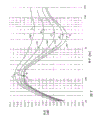
Fig. 4 A has described the expectation character of frequency response curve chart that appears at hearer's external ear place under the Sound reproducing environment.Curve 60 is to be the function of the sound pressure level (SPL) of unit measurement to frequency with the decibel.As can be seen from Figure 4A, sound pressure level is comparatively constant for all audible frequencies.Curve 60 can be by directly being positioned over a pair of desirable loud speaker hearer the place ahead and the similar equal-height position of its ear, and obtained by their playback pink noises.Pink noise refers to such a case, and promptly sound is distributed on the audio frequency spectrum, and each octave has equal energy.In fact, the flat frequency response of curve 60 may have fluctuating owing to the intrinsic acoustics defect influence of speaker system.
Sound pressure level before curve 60 expression hearer ears are handled.Again referring to Fig. 2 and 3, the flat frequency response of curve 60 representatives is with consistent to the sound of passenger's 48 emissions from instrument board 55 present positions along direction as shown A.People's ear is added on the acoustical signal by the acoustic response with himself, and this class sound of curve 60 representatives is handled.This acoustic response of people is partly determined by the outer auricle and the internal channel of ear.
Regrettably, the frequency-response characteristic curve of many automobile Sound reproducings system does not have the desired character shown in Fig. 4 A.On the contrary, loud speaker may be placed on disadvantageous place on the acoustics.Requirement with the human engineering aspect that satisfies other.Again referring to Fig. 2, the loud speaker 46 and 50 of car door-installation is placed in place convenient and that do not noted.But, in such position, because loud speaker 46 and 56 is with respect to the just simple placement of passenger 48, so the sound that loud speaker 46 and 50 sends may be spectrum distortion.The internal environment of automobile 40 such as passenger 48 the leg and the vehicle seat 45 of automobile, can cause absorbing the acoustical signal that is produced or making its amplitude distortion in addition.This class distortion is present in the upper frequency usually, and they are improvement targets of some prior art sound enhanced system.
The spectrum and the result of amplitude distortion be, the stereo sound image of passenger's 48 perception spatially is distortion, and it is satisfactory to make auditory perception be difficult to.Fig. 4 B-4D has described the spatial distortion degree of various automobile Sound reproducing system with graphics mode.The distorted characteristic curve representative that Fig. 4 B-4D is described is the periotic sound pressure level of hearer that unit records with the decibel.
The frequency response curve 64 of Fig. 4 B is on a declining curve in the sound pressure level greater than the frequency place of about 100Hz.Curve 64 expressions are installed on hearer below in the automobile, comprise the possible sound pressure characteristic curve that loud speaker produced of woofer and high pitch loudspeaker.For example, suppose that the loud speaker 46 of Fig. 2 comprises high pitch loudspeaker, so only the acoustical signal play of loud speaker 46 may present the response of Fig. 4 B thus.Suppose the pressure response that obtains Fig. 4 B in the automobile of Fig. 2, passenger 48 will be positioned the acoustic image that is produced anterior 42 lower position.
The certain tilt degree relevant with gradually falling curve 46 is easy to change, and may not be linear fully, and everything is all relevant with the quality and the accurate location of loud speaker in door skin 58 of the inside of automobile, loud speaker.For example, the inner ornaments of corium or vinyl will reflect more acoustical signal, particularly high frequency sound signal than fabric inner ornaments.The degree of spectrum distortion along with loud speaker apart from hearer's the placement distance and the increasing of orientation distance, evident difference is arranged.
Fig. 4 c is the diagrammatic representation of acoustic pressure-frequency characteristics 68, and wherein first frequency range of audio signal is a spectrum distortion, but the higher frequency band of signal is not distortion.Characteristic curve 68 can place hearer below and tweeter to place hearer's ear high level or flushes and obtain with it by being low to moderate mid frequency ludspeaker.Once more referring to Fig. 2, such be low to moderate mid frequency ludspeaker will be corresponding to loud speaker 46, and such tweeter (not shown) will place certain position on the instrument board 55.Adopt this arrangement, frequency response curve 68 is in about 100Hz place amplitude maximum, will reduce as the function of frequency from 100Hz to about 1000Hz.At 1000Hz, curve 68 increases again until maximum amplitude, and the increase of sound pressure level more than 1000Hz is the direct result that high pitch loudspeaker is placed Vehicular occupant 48 anterior position with not blocked.The acoustic image that is produced by characteristic curve 68 will have a low frequency component below the passenger 48 of Fig. 2, flushing the vicinity at passenger's ear has a high fdrequency component.
Fig. 4 D is the diagrammatic representation of acoustic pressure-frequency characteristics 70, and is wherein on a declining curve in the low-frequency range sound pressure level, in rising trend in the high band sound pressure level.Characteristic curve 70 is by such loudspeaker arrangement, promptly in the tremendously low frequency loud speaker place hearer below and tweeter places the hearer top and obtain.A kind of audio system that comprises loud speaker 46 and 56 of arranging like this corresponding to Fig. 2.High pitch loudspeaker is placed in the top cover of top, car of ear, can provide for it through passenger's ear that is not stopped than short path.Therefore, shown in the curve 70 of Fig. 4 D, may arbitrarily downgrade greater than all-bottom sound significantly greater than the sound pressure level at the frequency place of 1000Hz, near the hearer making experiences undesirable acoustic efficiency.The acoustic image that is produced by characteristic curve 70 will have following feature, and low frequency component is positioned at the passenger's 48 of Fig. 2 below, and high fdrequency component is positioned at passenger 48 top.
The acoustic feature curve representation of Fig. 4 B-4D obtainable and various sound pressure levels that hear for passenger 48 in 42 (shown in Figure 2) forwardly.In having the automobile reproducing environment of front and rear, can readjust the acoustic image in each part.Most of automobiles are to carry out the independent signal correction of this class, are equipped with independent forward and backward passage.In rear portion 44 spatial distortion being proofreaied and correct required Signal Regulation will decide according to the particular speaker position.For example, loud speaker 50 required free-air correction degree and the loud speakers of taking of Fig. 2 are basic identical to 46.Why so be because loud speaker 46 is in identical position with 50 respectively for anterior passenger 48 and back occupant.But, if the back channel speakers comprise or also have towards last loud speaker 52, will carry out adjusting in various degree so, with the spatial distortion of the rear portion listening space (having) of proofreading and correct vehicle 40.
The acoustic response curve of Fig. 4 B-4D only is several examples of how being play by various Sound reproducing systematic distortions about the audio signal at hearer's ear place.The order of accuarcy of space distortion will be looked playback system and reproducing environment and be very different on any given frequency.By implementing the preferred embodiment of the present invention of explanation herein, will produce apparent position with respect to fixing hearer for speaker system by apparent height and azimuthal coordinates definition, these highly and the position of azimuthal coordinates and actual loudspeaker different.
Fig. 5 has disclosed the detailed diagram of the preferred embodiments of the present invention.Preferred embodiment comprises stereo sound image correcting circuit 22, its an input left side and right stereophonic signal 26 and 28.Acoustic image correcting circuit 22 is divided into first frequency component and second frequency component by advantageously listening frequency spectrum, proofreaies and correct the spectrum density of the distortion of each sound system, and wherein the first frequency component comprises lower frequency, and the second frequency component comprises upper frequency.Each of a left side and right signal 26 and 28 is respectively by corresponding LFC low-frequency correction circuit 80,82 and high frequency correction circuit 84 and 86 individual processing.Should be pointed out that correcting circuit 80 and 82 in a preferred embodiment will be operated in is about " low " frequency range of 100 to 1000Hz, and correcting circuit 84 and 86 will be operated in and be about " height " frequency range of 1000 to 10000Hz.This and common audio frequency term are different, and generally low frequency is represented the frequency up to 100Hz, and intermediate frequency is represented the frequency between 100 to 4kHz, and the high frequency representative is greater than the frequency of 4kHz, and both should not obscure.
By separating the lower and higher frequency components of input acoustical signal, in a frequency range, can be independent of another frequency range and carry out the correction of sound pressure level.Correcting circuit 82,84,86 and 80 is revised input signal 26 and 28, so that these input signals are proofreaied and correct in spectrum that produces in loudspeaker reproduction and amplitude distortion.Signal that is produced and original input signal 26 and 28 are combined at separately summing junction 90 and 92 places.Left stereophonic signal L after the correction
C' and proofread and correct after right stereophonic signal R
C' send along output 94 and 96 respectively.
The correction stereophonic signal at output 94 and 96 places produces smooth at passenger's 48 (shown in Figure 2) ear place be the uniform frequency response.This free-air correction response produces an apparent sound source, as if when playing by the loud speaker 46 of Fig. 2, this apparent sound source is positioned passenger 48 dead ahead.In case sound source is appropriately located after the energy-correction of acoustical signal, stereo enhancement circuit 24 is just regulated stereophonic signal, the stereo sound image that is sent by this apparent sound source with broadening.As what will discuss in conjunction with Fig. 8 A and Fig. 8 B, stereo sound image intensifier circuit 24 may be regulated by stereo orienting device 30, compensates with the physical location to sound source.
In a preferred embodiment, the difference signal information that exists in 24 pairs of left sides of stereo enhancement system and the right stereophonic signal is carried out balance.The stereo enhancement system 24 that herein discloses and common unsettled sequence number are that 08/430751 patent application is similar.Relevant stereo enhancement system of the present invention also is disclosed in United States Patent (USP) 4748669 and 4866774, and these two United States Patent (USP)s are presented to one of identical inventor of the disclosed invention of the application, Arnold klayman.The disclosure of United States Patent (USP) 4748669, United States Patent (USP) 4866774 and patent application 08/430751 is herewith incorporated by reference, just like this paper comprehensively statement like that.
The signal L of 94 and 96 transmission along the path
CAnd R
CBe enhanced system's 24 inputs, and feedback is toward high pass filter 98.In fact filter 98 may comprise two independent high pass filters.Filter 98 is preconditioning filters, and its purpose of design is to reduce the bass component that is lower than about 100Hz, and these bass component may be present in the difference signal with being out of favour.The output of filter 98 is sent to difference signal generator 100.There is a difference signal (L in output 102 places
C-R
C), the left side after this difference signal representative is proofreaied and correct and the stereo audio content of right input signal.The output of stereo sound image correcting circuit 22 also directly is sent to and signal generator 104.Generation one of output 106 places and signal (L
C+ R
C), should and signal representative after proofreading and correct a left side and right stereophonic signal and.
Output 102 and 106 places present respectively toward independent level regulating device 108 and 110 with signal and difference signal.Ideal situation lower device 108 and 110 is potentiometer or similar variable impedance apparatus.Device 108 and 110 adjusting is normally manually carried out, with that exist and reference level signal and difference signal in the control output signal.This allows user can be according to reproducing sound type and according to user's personal like, designing stereo enhanced strength and aspect.And the increase of the reference level of signal will be given prominence to the audio-frequency information at the intermediate location place that is positioned between a pair of loud speaker.On the contrary, the increase of difference signal reference level will be given prominence to ambient sound information, thereby perceive the acoustic image of broad.Some music type and system configuration parameter is known or manual adjustments and infeasible audio frequency structure in, can cancel adjusting device 108 and 110, this just the level of requirement and signal and difference signal must pre-determine and be fixed.
The stereo enhancing equalizer 120 toward input 122 places is presented in the output of device 110.Equalizer 120 is composed shaping by difference signal is carried out filtering with low pass tone filter 124 and high pass tone filter 126 respectively to the difference signal that appears at input 122 places.Except by filter 124 and 126 regulatory functions that provided, the difference signal level is regulated separately by stereo directional circuit 130.The output signal of filter 124,126 and directional circuit 130 respectively along the path 132,134 and 136 from equalizer 120 output.
132, the 134 and 136 modification difference signals that transmit are the processing difference signal (L that appear on the output 140 along the path
C-R
C)
PComponent.This handles difference signal feed-in frequency mixer 142, this frequency mixer also receive from device 106 with signal and from the stereophonic signal L of output 94 and 96
CAnd R
CAll these signals are made up in frequency mixer 142, to produce the left output signal 30 and the right output signal 32 of enhancing to some extent and free-air correction.
Represent by following mathematical expression by 24 pairs of left sides of intensifier circuit and right output signal 30 and 32 adjustings of carrying out:
Lout=L
C+K1(L
C+R
C)+K2(L
C-R
C)
P (1)
Rout=R
C+K1(L
C+R
C)-K2(L
C-R
C)
P (2)
Although the input signal L in the above-mentioned equation
CAnd R
CRepresent desirable calibrated stereo source signal, but they can generate also by the single-tone source is synthetic.Can be disclosed in the United States Patent (USP) 4841572 of awarding to Arnold klayman equally for this type of stereo synthetic method that the present invention uses, this patent is cited as reference at Ben Chu.
The acoustic image correction characteristic curve
Fig. 6 A-6C is for the acoustic image that obtains from a stereophonic signal to reorientate, by the diagrammatic representation of the free-air correction of the given various degree of " low " and " height " frequency correcting circuit 80,82,84,86.
At first referring to Fig. 6 A, the various possible free-air correction level that correcting circuit 80 and 82 provides is depicted as the curve with different amplitude-frequency characteristics.Circuit 80 and 82 provide and proofread and correct or promote (being that unit is measured with dB) to greatest extent by calibration curve 150 expressions.Curve 150 is in rising trend in first frequency range of about 100Hz and 1000Hz.When frequency during greater than 1000Hz, the amplitude of curve is constant relatively.What curve 152 was represented is the practically negligible situation of correcting value.
For a person skilled in the art, the feature of exemplary filter is passband and the stopband that is separated by cut-off frequency.Although the representative of the calibration curve of Fig. 6 A-6C is typical traffic filter, can characteristic turn to passband, stopband and transition band.According to the feature of Fig. 6 A filter established of structure in addition, its passband more than about 1000Hz, transition band about 100 and 1000Hz between, and stopband is below about 100Hz.More than about 10kHz, transition band is between about 1kHz and 10kHz according to the passband of the filter of Fig. 6 B and 6C, and stopband is below about 1kHz.Because the filter that uses according to preferred embodiment only is the first rank filter, so definition is logical, the frequency of resistance and transition band only is a design object.Characteristic frequency strict for given circuit has obvious difference.
From Fig. 6 A-6C as can be seen, be uniformly basically in passband by the free-air correction of 80,82,84 and 86 pairs of audio signals of circuit, and in transition band, depend on frequency to a great extent.Change by regulating the function that acoustic correction amount that 22 pairs of audio signals of stereo sound image correcting circuit apply can be used as frequency, stereo sound image correcting circuit wherein can change the gradient of the transition band of Fig. 6 A-6C.The result is, the correction of frequency dependence be applied in 100 and 1000Hz between first frequency range, and put on 1000 to 10000Hz second frequency range.By regulating correcting circuit 80,82,84 and 86 independently, can obtain the infinite calibration curve of number.
According to preferred embodiment, the free-air correction of upper frequency stereophonic signal component is carried out between about 1000Hz and 10kHz.Energy-the correction of these signal components may be positive i.e. lifting, shown in Fig. 6 B, also may bear, i.e. decay is shown in figure C.Correcting circuit 84,86 given expanded reaches is characterized in that maximum lift curve 160 and minimum lift curve 162.Curve 164,166 and 168 representatives to never in unison the sound that sends of playback system carry out other required liftings at different levels of free-air correction.
Energy-calibration curve that Fig. 6 C describes is basically with opposite shown in Fig. 6 B.As previously shown, under the situation about above high pitch loudspeaker is installed on the hearer and with corresponding woofer or mid frequency ludspeaker, separating, may need the higher-frequency acoustical signal is decayed.By circuit 84 and 86 obtainable attenuations is variable, and the maximum attenuation amount is by curve 170 expressions, and the minimal attenuation amount is by curve 172 expressions.Intermediate curve 174,176 and therebetween some of 178 expressions may versions.
Because by represented being added in together of Fig. 6 A-6C curve, so adoptable feasible free-air correction curve ranges is wider between frequency 10 to 10000Hz than low frequency and higher-frequency correction factor.Fig. 6 D is the diagrammatic representation that an excursion of the composite space correction characteristic curve that provided by stereo sound image correcting circuit 22 has been provided.Particularly, solid-line curve 180 is represented the maximum space adjusting level of being made up of curve 150 (shown in Fig. 6 A) and curve 160 (shown in Fig. 6 B).Correction than low frequency can be from solid-line curve 180 at θ
1Change in the scope of appointment.Similarly, the correction of upper frequency can be from solid line 180 at θ
2Change in the scope of appointment.So, the lifting capacity that first frequency range to 100 to 1000Hz applies about 0 and 15dB between change, and the correction that 1000 to 10000Hz second frequency range is applied can change between-the 15dB at about 30dB.
Acoustic image strengthens characteristic curve
Talk stereo sound image enhancing of the present invention aspect now again, Fig. 7 with diagrammatic representation a series of stereoeffects strengthen or normalized curve.Signal (L in the above-mentioned equation 1 and 2
C-R
C)
PExpression be to make to compose difference signal after the processing of shaping according to the frequency response characteristic of Fig. 7.These frequency response characteristics are applied by equalizer shown in Figure 5 120 and part is deferred to the HRTF principle.
In general, difference signal is amplified selectively, environment or reverberation audible effect are strengthened, these audible effects may be present in the difference signal still to be covered by stronger direct sound wave.Under suitable degree, be easy to perceived in on-the-spot these ambient sound of performance.But under recording performance situation, ambient sound is with respect to playing existing the decay live.When acoustic image when a pair of loud speaker that places hearer the place ahead sends, take from the difference signal level of a pair of stereo left and right sides signal by lifting, this projection acoustic image can be by obvious broadening.
The stereoeffect curve 190,192,194,196 of Fig. 7 and 198 expressions be gain to the functional relation of audible frequency, its medium frequency form of taking the logarithm.Consider various audio reproducing systems, need be between the various equalization stages between each curve of Fig. 7.Particularly, in a preferred embodiment, the difference signal equalization stages is the function of loud speaker with respect to the physical location of hearer in the audio reproducing system.Curve 190,192,194,196 and 198 has generally shown the frequency profile feature, this feature and common pending application 08/430751 feature similarity described in detail.That is, low and higher signal frequencies promotes to some extent with respect to Mid Frequency.
According to preferred embodiment, the scope of the stereoeffect curve of Fig. 7 limits by being positioned at the maximum gain that about 125 to 150Hz place's numerical value are about 10-15dB.This maxgain value refers to each curve break of Fig. 7, through this point curve 190,192,194,196 and 198 slope from the occasion of becoming negative value.Such breakover point is marked with A, B, C, D and E in Fig. 7.The stereoeffect curve takes advantage of the speed of about 6dB to descend with each frequency multiplication when being lower than 125Hz.When being higher than 125Hz, the gain of Fig. 7 curve is about-2 to+10dB least gain breakover point with variable bit rate to value and reduces.Each least gain breakover point has evident difference between curve 190,192,194,196 and 198.Each least gain breakover point is marked with A ', B ', C ', D ' and E ' respectively.Least gain breakover point place frequency is changed to about 5kHz of curve 198 from about 2.1kHz of curve 190.Curve 190,192,194,196 and 198 gain increase from least gain frequency separately, until about 10kHz.During greater than 10kHz, it is steady that the gain of each curve begins to become.But the gain of each curve will continue to increase, and promptly almost be the highest frequency that people's ear can be heard until about 20kHz.
Aforesaid gain and frequency numerical value only are design objects, and perhaps actual numerical value is different for different circuit, and this actual value on employed element is decided.In addition, signal level device 108 and 110 adjusting will have the greatest impact and minimum gain value, and the gain isolation between maximum gain frequency and the least gain frequency.
According to Fig. 7 curve difference signal is carried out equilibrium, its purpose is to promote on the statistics to have more low intensive difference signal component, and can too not strengthen higher-strength difference signal component.The higher-strength difference signal component of typical case's stereophonic signal it is found that it is among frequency values is about 1 to 4kHz Mid Frequency.People's ear has tangible susceptibility to these identical Mid Frequencies.So,, reproduce the hearer of sound field under closing to surround fully to be in, so the audio frequency effect of a left side that is enhanced and right output signal 30 and 32 has had tangible improvement because ambient sound is strengthened selectively.Although stereoeffect curve 190,192,194,196 and 198 general equilibriums that provided are to utilize the high pass of equalizer 120 and low pass filter to finish, also can utilize stop-band filter to finish same Signal Regulation.Equally, implement the stereoeffect curve with digital signal processor and in most of the cases also will reflect design constraint discussed above more accurately.With regard to one the simulation embodiment with regard to, if corresponding to the frequency of minimum and maximum gain have+or-20% variation also be feasible.The stereo reinforced effects that still can produce expectation that departs from from desirable index like this, just its result no longer is optimum.
As can be seen from Figure 7, the difference signal frequency that is lower than 125Hz is by using stereoeffect curve 70, and its lifting capacity descends.It is that bass too increases the weight of that this decline is intended to avoid to unusual low frequency.With regard to many audio reproducing systems, the audio difference signal of this low-frequency range is amplified, can produce the unhappy and unpractical acoustic image that makes us with too much bass response.The example of this class audio reproducing system comprises near field or low-power audio system, for example multi-media computer system, and family stereo system.Big power consumption may cause amplifier during high-amplitude promotes " slicing " in these systems, perhaps may damage the element of the voicefrequency circuit that comprises loud speaker.The bass response of restriction difference signal also helps to avoid these problems in audio frequency enhancing in most near fields is used.To the specific descriptions of other acoustic advantage of difference signal equilibrium referring to common pending application 08/430751.
According to preferred embodiment, relevant at the numerical value of the audio environment allowance below nominal size signal equalization that static audience is arranged and actual loudspeaker type and they and hearer's relative position.The Principles of Acoustics of this judgment basis can appropriately be explained in conjunction with Fig. 8 A and 8B.Fig. 8 A and 8B are intended to represent these class Principles of Acoustics that the orientation about speaker system changes.
Fig. 8 A describes be loud speaker 200 and 202 be positioned over hearer 204 both sides slightly on the front and point to the top view of the Sound reproducing environment of hearer's direction.Loud speaker 200 and 202 also is positioned over hearer 204 belows, and its height and position is similar to loud speaker shown in Figure 2 46.Reference planes A and B aim at hearer 204 ear 206,208.Plane A and B with shown in hearer's sight line parallel.
Suppose that loud speaker 200 and 202 will suffer certain spectrum distortion and/or amplitude distortion before the sound that reproduces under the audio environment of Fig. 8 A is touching ear 206 and 208.This class distortion for example can be by 64 expressions of curve shown in Fig. 4 B, when this class distortion when loud speaker 200 and 202 is emitted will produce the switching acoustic image in space.By using 22 pairs of spectrum distortions of acoustic image correcting circuit to compensate, will be through loud speaker 200 and 202 audio signals of playing to 204 1 apparent acoustic images of hearer.In the example of Fig. 8 A, the height of this apparent acoustic image will be different with actual sound source.And then by using figure image intensifying of the present invention aspect, this apparent acoustic image will obtain the space to be strengthened, with broadening apparent acoustic image.The acoustic image that is produced will be corresponding to rising from loud speaker 210 that is represented by dotted lines and 212 enhancing acoustic image.
The enhancing of apparent acoustic image is finished by balanced difference signal selectively, i.e. the gain of difference signal is along with the difference of frequency can be different.The desired value of the curve 190 expression difference signal equilibriums of Fig. 7, the actual loudspeaker position is corresponding to virtual speaker 210 and 212.But when loud speaker inwardly points to the hearer, as the loud speaker 200 of Fig. 8 A and 202 o'clock, acoustics perceived effect generation marked change, this need be to the numerical value correct of difference signal equilibrium.Particularly, be derived from loud speaker 200 and become θ with relative reference plane A with B with 202 direct sound field sound
1The angle at angle enters the ear 206 and 208 of audition.When loud speaker is positioned over the place ahead far away, angle θ
1Reduce.Referring now to Fig. 8 B,, provide rising tone playback system among the figure, its a pair of loud speaker 214 and 216 places the place ahead of hearer by locating down.In this allocation plan, the direct sound field sound that loud speaker 214 and 216 sends is with incidence angle θ
2Enter in hearer's the ear 206 and 208 angle θ
2Less than angle θ
1
Most loud speakers are characterised in that angle of flare, or the pack feature of acoustic radiation.The angle of flare of the sound of given frequency will increase and reduce along with frequency.The result is that hearer 204 will be in outside the normal pack orientation of these two loud speakers when loud speaker 200 and 202 forwards moves to the position of Fig. 8 B.When this happens, hearer 204 will slowly lose the perception to Mid Frequency and higher Mid Frequency.In addition, this effect may be strengthened under the situation of miniature loudspeaker, and this is because the bigger loud speaker of angle of flare of less loud speaker narrow.
In order to compensate the loss of intermediate frequency to higher intermediate frequency sound, the gain of difference signal obtains corresponding lifting in same frequency range.When the physical location of loud speaker 200 and 202 was forwards mobile, the Mid Frequency gain compensation must increase.Since 190 relative attenuations of stereoeffect equalizer curve this identical Mid Frequency, so revise level of attenuation, inwardly give prominence to this situation to take into account Fig. 8 A and 8B loud speaker.Therefore, may adopt the curve 196 of Fig. 7, Fig. 8 B system be carried out the space strengthen, to produce the apparent sound source of loud speaker 218 and 220, curve 192 then may be enough to the system of Fig. 8 A is carried out the space enhancing.By the difference signal in Mid Frequency or the higher Mid Frequency is promoted, apparent acoustic image hearer 204 relatively appropriately is orientated.The appropriate orientation of acoustic image makes loud speaker 200,202, and 214 and 216 positive effects that inwardly rotate are so that apparent diffusion Shu Zhixiang hearer 204.
The stereo sound image correcting circuit
Fig. 9 is the detailed schematic diagram of the preferred embodiment of stereo sound image correcting circuit 22.Circuit 22 is divided into left signal correcting circuit 230 and right signal correcting circuit 232.Left and right correcting circuit 230 and 232 is used for its input signal 26 is separately carried out identical Signal Regulation with 28.Therefore, the index of left signal correcting circuit 230 should be identical with the index of right signal correcting circuit 232.For simplicity's sake, hereinafter will only make an explanation with regard to the circuit connection and the functional performance of right signal correcting circuit 232.
Right stereophonic signal 28 is imported by right signal correcting circuit 232, and is sent to variable resistor 234.Variable resistor 234 or claim potentiometer, with 236 groups of similar variable resistors in the left signal correcting circuit 230 together.This is all to act on circuit 230 and 232 comparably in order to ensure any adjusting measure that right signal correcting circuit 232 is done, and vice versa.Right stereophonic signal is 238 terminals " 1 " that are sent to switch 240 along the path also, and switch 240 plays the bypass effect according to the variation of its position, avoids stereophonic signal 28 to carry out equilibrium.
From variable resistor 234, input signal is connected to the in-phase input end 242 of first amplifier 244.Inverting input 246 is connected to ground through resistance 248, and it also links to each other with an end of feedback resistance 250.The opposite end of feedback resistance 250 is connected to the output 252 of amplifier 244.
Output 252 is sent to three independent positions of circuit 232.Particularly, output 252 links to each other with 260 with high-pass filtering circuit 258, and it also is connected to mixting circuit 264.About circuit 258, send the in-phase input end 268 of amplifier 270 to through capacitor 266 from the signal of output 252 outputs.Input 268 also is connected to ground through resistance 272.The inverting input 272 of amplifier 270 is connected to ground through resistance 274, and is connected to the output 280 of amplifier 270 through feedback resistance 276.Filter circuit 260 has similar configuration to circuit 258, and its element is respectively 284,286,288,290,292 and 294.
The corresponding output end 294 of output 280 and amplifier 288 is presented respectively toward a pair of variable resistor 282 and 286.The variable resistor 298 of resistance 282 and left signal correcting circuit 230 links, and variable resistor 296 also links with variable resistor 300 similarly.Each resistance 282 and 296 has output 302 and 304 separately.
Mixting circuit 264 comprises an amplifier 306, and its in-phase input end 308 is connected in ground.The signal that is added on output 302,304 and 252 enters mixting circuit 264, and is sent to the inverting input 310 of amplifier 306.Resistance 312,314 and 316 is connected between inverting input 310 and output 252,302 and 304.In addition, the signal on the output 302 is sent to amplifier 306 through switch 318, and switch 318 can be the manual or automatic selector switch in two-position.Feedback resistance 320 is connected to inverting input 310 output 322 of amplifier 308.
The in-phase input end 326 of amplifier 324 is connected to earth potential, and inverting input 328 is connected to output 322.In addition, this inverting input is connected to switch 318 through resistance 330.The signal on the output 302 is sent to input 328 through resistance 330 in the position 2 when switch 318 is in.Resistance 332 and electric capacity 334 are connected in parallel between the input 328 and output 336 of amplifier 324.Then output 336 is connected to the position " 2 " of switch 240.Switch 240 preferably links with similar by-pass switch 338.
Left and right energy-correcting circuit 230 and 232 is revised the range weight of input stereo audio signal, with the right stereophonic signal 342 of the left stereophonic signal after produce power-correction 340 and energy-correction.Once more for for purpose of brevity, the generation to the right signal 342 of energy-correction is only described.But understandable is the generation that same principle also is applicable to the left signal 340 of energy-correction.
During work, input stereo audio signal 28, and by the handling of 232 pairs in circuit, arbitrarily downgrade with the distorted sound that correction signal 28 produces when audio reproducing system is play.Originally, variable resistor 234 allows to regulate incoming signal levels, and such regulating action may be used for the overall gain of control circuit 232, perhaps in some cases input signal 28 by previous circuit obviously in the decay with it lifting.Resistance 234 can be the 10 kilo-ohms of clockwise potentiometers of standard that link with variable resistor 236.
Amplifier 244 is designed to voltage follower, and it plays isolation buffers between the other parts of input signal 28 and circuit 232.The level adjustment signal through buffering that appears on the output 252 is presented toward circuit 258, locates this signal by a single-order high pass filter with corner frequency that numerical value is about 5kHz at this.In a preferred embodiment, high-pass filtering is to be finished by the RC combination of electric capacity 266 and resistance 272, and the numerical value of electric capacity 266 is 3900 pico farads, and the numerical value of resistance 272 is 10 kilo-ohms.The gained high pass filtered signals that appears on the input 268 cushions by the amplifier 270 with unit gain work.The signal amplitude that appears on the output 280 can correspondingly increase or reduce by regulating variable resistor 282.
Similarly, circuit 260 input is from the signal of output 252, and by the RC filtering combination of electric capacity 284 and resistance 286 signal handled.Being connected in series of electric capacity 284 and resistance 286 also can be used as high pass filter, but its corner frequency is about 500Hz.This is by electing the appearance value of electric capacity 284 as 0.022 microfarad, and the resistance of resistance 286 is elected 10 kilo-ohms as and finished.Filtered then input signal is through amplifier 288 bufferings, and the quilt feedback is toward level adjustment variable resistor 296.
The filtering signal that leaves resistance 282 and 296 302 and 304 is sent to mixting circuit 264 along the path respectively.In addition, the primary signal 28 of only making gain-adjusted also is sent to frequency mixer 264 through resistance 312.Frequency mixer with all three input signal combine produce power-correction output signal.
Each represented free-air correction level of Fig. 6 A-6C is to realize 296/300 and 282/298 by regulating interlock resistance.Particularly, the lower frequency calibration curve of Fig. 6 A can realize that by the gained result who measures output 336 places the variable resistor 282 that meanwhile influences the upper frequency correction is set as minimum value.According to this plan of establishment, switch 318 is grounded, and upper frequency is not proofreaied and correct.Therefore, the scope of lower frequency correction obtains by regulating resistance 296.Like this, inverting amplifier 306 with the filtering signal on the path 304 with combine from the primary signal of output 52.The curve 152 of Fig. 6 A is represented unit gain, and circuit 232 only allows input signal 28 pass through thus, and does not do any free-air correction.This result is set as zero impedance at resistance 296, obtains when making input 310 ground connection of amplifier 306 thus.When the numerical value of resistance 296 increased, increasing filtering signal was added on the primary signal, thereby the signal in 100 to the 1000Hz scopes is carried out free-air correction.When resistance 296 is set as maximum value, the signal of lower frequency is carried out free-air correction completely, shown in the curve 150 of Fig. 6 A.
Any correction that the curve representative of Fig. 6 B is done by cancellation circuit 260, the resistance that is about to resistance 296 is made as zero, and switch 318 is placed the gained result of shown position 1.The regulating action of variable resistor 282 made in upper frequency, produce required lifting, shown in Fig. 6 B.On the contrary, the decay of the represented upper frequency of Fig. 6 C realizes by switch 318 being arranged on position 2.In this position, the output of filter circuit 258 is sent to independent inverting amplifier 324.Then amplifier 306 and 324 will from the filtering signal of path 302 and 304 in succession and the paraphase stage combine.Particularly, from the signal in path 304 and from the signal of output 252 at first by amplifier 306 combinations, be anti-phase signal and the output signal combination that comes self-resistance 282 at output 322 gained then.
When by amplifier 306 combination, from the filtering signal of path 302 and 304 with respect to the gain of input signal by feedback resistance 320 and 332 definite with the impedance ratio of resistance 314 and 316.Have the audio reproducing environment that distorted sound is arbitrarily downgraded for great majority, the numerical value of these resistance can be set, so that filtering signal is about 3: 1 to the maximum gain ratio of input signal.In a preferred embodiment, resistance 320 and 332 resistance are about 10 kilo-ohms, and the resistance of resistance 314 and 316 is about 3.32 kilo-ohms.By regulating variable resistor 282 and 296 and selector switch 318, all other free-air corrections of level that can obtain representing among Fig. 6 D.
The circuit of Fig. 9 is only represented a preferred embodiment of stereo sound image correcting circuit.Can be understood that by those of ordinary skill in the art, consider that the specific reproduction environment can do some change to the design of circuit 22, depart from the protection range of attempting of the present invention and be unlikely.For example, scope is that energy-corrections frequency range of 0.1-1kHz (" low " frequently proofread and correct) and 1kHz-10kHz (" height " proofreaied and correct frequently) can be passed through selective filter circuit 258 and 260 interior RC impedance combination and change.In some cases, may need three or more a plurality of this class energy-correction frequency range.Should also be noted that and select for use electric capacity 334 to be intended to avoid circuit 22 to vibrate, may make circuit 22 that this vibration takes place in the discrete parasitic capacitance of implementing to exist in the structure.Electric capacity 334 may not need in the structure to be implemented at the PC of circuit 22 plate or semiconductor.
The stereo sound image intensifier circuit
Figure 10 is the schematic diagram of stereo sound image intensifier circuit 24.Circuit 24 is used for a left side and the right signal L after broadening is proofreaied and correct
CAnd R
CAccording to preferred embodiment, energy-correction left signal 340 is by the past resistance 350 of feedback, resistance 352 and electric capacity 354.Energy-correction right signal 342 is by the past electric capacity 356 of feedback and resistance 358 and 360.
Resistance 350 is connected to the homophase terminal 362 of amplifier 366.Same terminal 362 also links to each other with resistance 368 with resistance 360.Amplifier 366 is designed to summing amplifier, and its end of oppisite phase 370 is connected to ground through resistance 372.The output 374 of amplifier 366 is connected to end of oppisite phase 370 through feedback resistance 376.Generate and signal (L at output 374
C+ R
C), this signal is represented left signal 340 and right signal 342 and several, is presented the end toward variable resistor 378, variable-resistance opposite end ground connection.For making 366 pairs of signals of amplifier 340,342 do appropriate summation, resistance 350,360,368 and 376 numerical value are about the twice of resistance 372 in a preferred embodiment.
Second amplifier 380 is designed to " poor " amplifier.The end of oppisite phase of amplifier 380 links to each other with resistance 384, and resistance 384 is connected in series with electric capacity 354 then.Similarly, the anode 386 of amplifier 380 is by the be connected in series received signal 340 of resistance 388 with electric capacity 356.Terminal 386 also is connected to ground through resistance 390.The output 392 of amplifier 380 is connected to end of oppisite phase through feedback resistance 394.Output 392 also links to each other with variable resistor 396, and variable resistor 396 is ground connection then.Although amplifier 380 is designed to " poor " amplifier, its function also can be characterized by the summation of right input signal and negative left input signal, to generate difference signal (L
C-R
C).Therefore, amplifier 366 and 380 is configured for generating the summation network with signal and difference signal respectively.
These two R that are connected in series
CNetwork comprises parts 354/384 and 356/388 respectively, and their effect is to input signal L as high pass filter
CAnd R
CVery low or low frequency signal decay.These R
CFilter is corresponding to the device 98 of Fig. 5.In order to obtain appropriate frequency response, the cut-off frequency W of device 98 according to Fig. 7 equalizer curve
COr-the 3dB frequency should be about 100Hz.Accordingly, in a preferred embodiment, electric capacity 354 and 356 appearance value are 0.1 microfarad, and the resistance of resistance 384,388 is about 33.2 kilo-ohms.So by making the feedback resistance 394 and the numerical value of damping resistance 390 satisfy following formula (3):
(3)
Output 392 will be represented the difference signal after gain is 2 amplification.Be actually in the phase place of output 392 place's signals anti-phase, thereby draw R
C-L
C
The particular phases of difference signal has significance when determining the final composition of output signal.It only is the L of 180 degree that this paper uses term " difference signal " expression phase difference
C-R
CAnd R
C-L
C, this also is the common way of this area.What those having ordinary skill in the art will appreciate that is that amplifier 380 can so dispose, and makes as long as the difference signal on a left side and right output keeps out-phase state each other, " left side " difference signal L
C-R
CAppear on the output 392, rather than R
C-L
C
The result who input signal is done high-pass filtering is, the difference signal on output 392 will have the low frequency component of having decayed in the frequency range less than about 125Hz, and it reduces with the speed of every octave 6dB.Can be to the low frequency component filtering of the difference signal in the equalizer 120 (as shown in Figure 5), and do not use filter 98.But, because the filter capacitor under the low frequency is quite big, so preferably carry out this filtering in input stage, to avoid loading foregoing circuit.
Variable resistor 378 and 396 can be the simple potential meter, and they are regulated by mobile sliding contact 400 and 402 respectively.The level that appears at the difference signal in the gained output signal can or be regulated sliding contact 402 automatically and be controlled by manual, remote control.Similarly, level part that exist and signal is determined by the position of sliding contact 400 in the output signal after the enhancing.Contact 402 " space " control that the defending party to the application is called the gained acoustic image is set, the setting of contact 400 is " " center " control.
On the sliding contact 400 with the inverting input 404 of resistance 408 feedback of signal through being connected in series toward the 3rd amplifier 406.Identical and signal on sliding contact 400 is also through the inverting input 410 of independent series resistance 414 feedbacks toward the 4th amplifier 412.Amplifier 406 is designed to the difference amplifier, and its end of oppisite phase 404 is through resistance 416 ground connection.The output 418 of amplifier 406 also links to each other with end of oppisite phase 404 through feedback resistance 420.
The anode 422 of amplifier 406 is the summing junctions along one group of signal of each signal path 426.Terminal 422 is through resistance 424 ground connection.Difference signal after the level adjustment sends from sliding contact 402, and is split into three, transmits through 428,430 and 432 respectively.Consequently three difference signals of regulating separately appear at an A, B and C respectively.Correspond respectively to the signal on the output 132,136 and 134 of Fig. 5 at the signal at an A, B and C place.The difference signal of putting as shown in the figure after the adjusting at B and C place sends anode 422 to through fixed value resistance 432 and 436.Difference signal after some A regulates at the place is sent to terminal 422 through variable resistor 438.
The signal representative at Node B place appears at the signal skew of difference signal after filtering through level adjustment at electric capacity 444 two ends, electric capacity 444 ground connection.The RC network of electric capacity 444 and resistance 446 plays low pass filter, and it carries out filtering to the difference signal on the sliding contact 402.
This low pass filter is corresponding to the filter 124 of Fig. 5.According to preferred embodiment, the cut-off frequency of this RC network is about 200Hz.If resistance 446 is 1.5 kilo-ohms, electric capacity 444 is 0.47 microfarad, and driving resistor 434 is 20 kilo-ohms, and so such cut-off frequency can be realized.
At node C, the RC combined filter that difference signal is made up of resistance 446 and electric capacity 448, resistance 446 are connected between node C and the ground, and electric capacity 448 is connected between node C and the sliding contact 402.Such filter is corresponding to the high pass filter 126 of Fig. 5.Gained difference signal component is through the terminal 422 of driving resistor 436 feedbacks toward amplifier 406.The cut-off frequency of high pass filter 126 is designed into about 7kHz, and its gain for Node B is-6dB.If the appearance value of electric capacity 448 is 4700 pico farads, the resistance of resistance 180 is 3.74 kilo-ohms, and so such cut-off frequency can be realized.
At an A place, without the selectivity equilibrium, promptly be sent to resistance 440 from the level adjustment difference signal of sliding contact 402.Therefore, the signal at some A place is just evenly decayed on all frequencies.The signal at some A place is done further decay by the impedance of variable resistor 438, and the resistance of resistance 438 is regulated by moving relevant sliding contact 442.
Variable resistor 438 can be 100 kilo-ohms of potentiometers of standard, will change stereo booster stage to its adjusting, to proofread and correct the orientation of loud speaker with respect to the hearer.By reducing the resistance of variable resistor 438, the reference level of difference signal increases.This causes the corresponding lifting in the Mid Frequency amplitude, overcomes the decay of filter 124 and 126 (shown in Figure 5) to these frequencies with part.Once more referring to Fig. 7, the stereoeffect equalizer curve that puts on the difference signal reduces along with the resistance of resistance 438, is changed to curve 198 from curve 190.Press as the method, the level of poor selectivity signal equalization can part or almost all reductions.That is, the amplitude regulated quantity as frequency function will obviously reduce on midband.Suitably curve is above selected in conjunction with the Principles of Acoustics of Fig. 8 A and Fig. 8 B discussion.
If stereo sound image correcting circuit 22 and stereo sound image intensifier circuit 24 are applied to known reproducing environment, variable resistor 438 and resistance 440 can be replaced by the single fixed resistance with required impedance so.In a preferred embodiment, resistance 438 and total resistance of 440 will change between 20 and 100 kilo-ohms, to take into account most of reproducing environment factors.Adopt such design, the resistance of resistance 424 is about 27.4 kilo-ohms.
The end of oppisite phase 410 that difference signal is also presented past amplifier 412 through the tandem compound and the fixed resistance 452 and 454 of variable resistor 450 and fixed resistance 451 after the modification at circuit position A, B and C place.Right signal 342 after these amended difference signals and signal and the energy-correction is along 456 transmission of one group of signal path.These signals from group 456 are made up at terminal 410 places of amplifier 412.Amplifier 412 is configured an inverting amplifier, its plus end 458 ground connection, and feedback resistance 460 is connected between terminal 410 and the output 462.Regulate the resistance of variable resistor 450, make it identical with resistance 438.For making 412 pairs of signals of inverting amplifier carry out appropriate summation, the resistance of resistance 452 is 20 kilo-ohms, and the resistance of resistance 454 is 44.2 kilo-ohms.The resistance in the stereo enhancement system 24 and the accurate numerical value of electric capacity can changes, but its ratio should remain adequate value, to obtain booster stage accurately.The other factors that may influence these passive component numerical value has the power requirement of enhanced system 24 and the characteristic curve of amplifier 370,380,406 and 412.
Signal on the output of amplifier 406 is presented through driving resistor 464, to generate the left output signal 30 that strengthens.Similarly, the signal at output 462 places of amplifier 412 transmits through driving resistor 466, produces the right output signal 32 that strengthens.The typical resistance of driving resistor is about 200 ohm.
During work, the difference signal component at an A, B and C place reconfigures at the terminal 422 of difference amplifier 406 and terminal 410 places of amplifier 412, to form the difference signal (L after handling
C-R
C)
PIdeally, be used for producing (L
C-R
C)
PThe expected range of stereoeffect curve be characterized as being maximum gain at about 125Hz with greater than 7kHz, least gain is between about 2100Hz and 5kHz.Difference signal after the processing also gets up with one of a left side or right signal and with signal combination, generates output signal Lout and Rout.Left side after the enhancing and right output signal can be by above-mentioned math equation (1) and (2) expressions.K1 value in equation (1) and (2) is by the Position Control of sliding contact 400.The k2 value is by the Position Control of sliding contact 402.
Figure 11 has described an alternate embodiment of stereo sound image intensifier circuit 24.The circuit of Figure 11 is similar to FIG. 10, and the difference signal that its representative produces a pair of stereo audio signal selectively carries out balanced other method.Stereo sound image intensifier circuit 500 is that produce and different with the circuit 24 of difference signal and Figure 10.
At circuit 500, left and right energy- correction signal 340 and 342 is by the negative input end of difference feed-in mixer amplifier 502 and 504.But for generate and and difference signal, a left side and right signal 340 and 342 are connected to the anti-phase terminal 510 of first amplifier 512 through resistance 506 and 508 separately.Amplifier 512 is configured inverting amplifier, its input 514 ground connection, and be furnished with a feedback resistance 516.Generating and signal at output 518, is anti-phase and signal-(L in this example
C+ R
C).After making level adjustment, present toward remaining circuit with signal then by variable resistor 520.Because in the circuit 500 with signal be anti-phase, so it is presented the in-phase input end 522 toward amplifier 504.Therefore, amplifier 504 need be provided with a current balance type resistance 524 now between in-phase input end 522 and earth potential.Similarly, a current balance type resistance 526 is set between inverting input 528 and earth potential,, generates output signal 32 so that carry out correct summation by amplifier 504.
In order to generate difference signal, anti-phase summing amplifier 530 receives left input signal and and signal at inverting input 532.Input signal 340 before arriving at input 532, flow through electric capacity 534 and resistance 536.Similarly, the anti-phase and signal flow at output 518 places is through electric capacity 540 and resistance 542.Parts 534/536 carry out bass filtering with the RC network that parts 540/542 produce to audio signal, and this point is illustrated in conjunction with a preferred embodiment.
Amplifier 530 has the in-phase input end 544 and a feedback resistance 546 of a ground connection.For this alternative arrangements of Figure 11, produce difference signal R at output 548 places of amplifier 530
C-L
C560 pairs of difference signals of variable resistor are regulated then, and with its feed-in remaining circuit.The received resistance value of circuit 500 is as follows, and resistance 506,508,516 and 536 is 100 kilo-ohms, and resistance 542 and 546 resistances are 200 kilo-ohms, and the appearance value of electric capacity 540 is 0.15 microfarad, and the appearance value of electric capacity 534 is 0.33 microfarad.Except that above-mentioned, the remaining circuit of Figure 11 is identical with Figure 10.
Stereo sound image enhanced system 24 can be only constitutes with four active parts, and these active parts are normally corresponding to the operational amplifier of amplifier 366,380,406 and 412.These amplifiers are easy to make the Quadrilateral assembly on the single semiconductor chip.Finish other required parts of stereo enhancement system and include only 29 resistance (except the driving resistor) and 4 electric capacity.The circuit 500 of Figure 11 can and comprise that only 28 resistance of potentiometer make with a quadrature amplifier, 4 electric capacity.It is integrated circuit encapsulation shape that circuit 24 and 500 can be made the multi-lager semiconductor substrate.
Except that the embodiment of Figure 10 and 11, also have other way that components identical is interconnected, so that stereophonic signal is carried out the stereoeffect enhancing according to the present invention.For example, a pair amplifier that constitutes the difference amplifier can receive a left side and right signal respectively, can also receive separately and signal.Like this, amplifier will produce left difference signal L respectively
C-R
CWith right difference signal R
C-L
C
The stereo sound image enhancing that intensifier 24 is provided is suitable for utilizing the high-quality stereophonic recording specially.Specifically, different with previous analog tape or vinyl records dish is that current stored digital recording can comprise difference signal in comprising the broad spectrum of bass be stereo information.By the difference signal lifting capacity in the restriction bass, can avoid on these frequencies, difference signal too being amplified.
But, according to the difference of Sound reproducing environment, may wish to promote the bass frequencies of audio signal, may be to compensate owing to acoustic image relocates and be orientated the bass loss that causes.Figure 12 has described the low boost circuit 550 that supplies an alternative embodiment of the present invention to use, and reduces with any this class in the compensation bass response.Low boost circuit 550 with signal be target, bass promptly very the great majority of low frequency information reside in this and the signal.
Circuit 550 has an input A, it by with receive and signal being connected of output 374 of Figure 10 amplifier 366.Regulated by variable resistor 552 with the level of signal, this variable resistor can be 10 kilo-ohms a potentiometer.Variable resistor 552 can adopt manual user to regulate and be provided with, if perhaps required bass boost amount is known, resistance 552 can replace with suitable fixed resistance.The level adjustment and the signal that leave resistance 552 then pass through second-order low-pass filter, and this filter is made up of resistance 554,556 and electric capacity 558,562.The gained filtering signal appears at the in-phase end of operational amplifier 564.Amplifier 564 is configured a voltage follower, to avoid loading this second order filter.In a preferred embodiment, the gain of amplifier 564 is made as maximum 2 by selecting substitutional resistance 566 and 568, and resistance 566 and 568 is done respectively from end of oppisite phase to form a feedback loop to ground and being connected from end of oppisite phase to output.In a preferred embodiment, resistance 554,566 and 568 is 10 kilo-ohms of resistance, and resistance 556 is 100 kilo-ohms of resistance, and the appearance value of electric capacity 558 is 0.1 millifarads, and the appearance value of electric capacity 562 is 0.01 millifarads.The selection of aforementioned components value makes by regulating resistance 552, can amplify the bass that is lower than about 75Hz selectively.
The output signal of amplifier 564 is split into two-way, and every road is contained fixed resistance 578 and 580 respectively.One tunnel output is marked with X, and it links to each other with the end of oppisite phase 404 of the amplifier 406 of Figure 10.Similarly, the output that is marked with X ' links to each other with the end of oppisite phase 410 of amplifier 412.During work, the further lifting of bass can be finished by the ratio that changes resistance 578,580 and resistance 420,460 respectively.For example, in a preferred embodiment, resistance 578 and 580 numerical value will for 420 and 426 half, make that through the amplifier 406 of Figure 10 and 412 gain be 2.Therefore, by regulating resistance 552, the overall gain of low boost circuit 550 can be to change between 4 maximum gain and the zero gain in value.
Be appreciated that if desired, can replace the stereo enhancement system of system 24 with a kind of modification of stereo enhancement system.For example, the embodiment of the system that in United States Patent (USP) 4748669 and 4866774, discloses to the difference signal in the special frequency channel with carry out equilibrium with the relative amplitude of signal.
Except that automobile, the present invention is applicable to the closed or outdoor audio reproducing environment that miscellaneous reproduction sound is compared with hearer's perception spatial distortion.The present invention also can be used for the environment that those hearers are not in a fixed position.
Figure 13 describes a kind of so outdoor audio reproducing environment, and its outdoor loud speaker 570 and 572 produces the have living space stereo sound image of distortion with respect to hearer 574. Loud speaker 570 and 572 can place near the face of land, as shown in figure 13, perhaps places other all places, provides stereo with the outdoor listening zone to broadness.Outdoor loud speaker 570 and 572 orientation problem on the part degree be undoubtedly by except that the other factors of optimal acoustic response definite.Such location and no matter it be near the ground, ceiling, or around leaf, all may make the sound pressure level distortion of sound on some frequency range of hearer's perception.By adopting stereo sound image correcting circuit 22, can proofread and correct gained distorted sound picture, the former reason stereo sound image intensifier circuit 24 according to explanation is herein strengthened then.The result is can produce and fall into the apparent acoustic image of expecting in the scope of listening to 576.
Consider moving of listening zone broad and hearer 574, some are the omni-directional loud speakers to the loud speaker 570 of Figure 13 outdoor loud speaker similar with 572.At such audio reproducing environment, needn't compensate as mentioned in conjunction with Fig. 8 A and Fig. 8 B described in to the reduction of higher Mid Frequency.Therefore, best enhancing result is the stereoeffect curve 190 by application drawing 7 under the environment of Figure 13, realizes to strengthen through loud speaker 570 and 572 energy-correction stereophonic signals of playing.
Figure 14 has described another audio reproducing environment, and it contains the enforcement of acoustic correction apparatus 20.Specifically, illustrated electronic keyboard instrument 590 has the loud speaker 592 and 594 that is placed under the keyboard 596.For the operator's (not shown) that is positioned at before the electronic keyboard 590, loud speaker 592 and 594 is arranged on operator's ear below and is in the disadvantageous position of acoustics.In order to proofread and correct the issuable spatial distortion of this laying method because of loud speaker 592 and 594, acoustic correction apparatus 20 is revised the audio signal that electronic keyboard 590 produces.According to principle discussed herein, can produce the apparent acoustic image of so reorientating, they seem to send from the apparent loud speaker of drawing with dotted line 598 and 600.Different with the environment of Fig. 8 B is, the required directivity of the audio reproducing environment of Figure 14 is probably owing to loud speaker 592 and 594 relative operators' location becomes minimum.Therefore, the curve 190 of Fig. 7 may be suitable for the acoustic image of reorientation is carried out the space enhancing.
The complete acoustic correction apparatus 200 of Pi Luing is easy to be realized by following scheme herein: there is the terminal of regulating suitable resistance (1) digital signal processor (2) discrete circuit element (3) hybrid circuit structure or (4) in semiconductor chip.Active user's adjusting comprises low frequency and high-frequency energy-corrected value, and various signal levels adjustings comprise and regulate with difference signal level and orientation.
Through above-mentioned explanation and accompanying drawing, show that the present invention has very important advantage on current Acoustic correction and stereo enhancement system.Although above-mentioned detail specifications shows, describes and points out basic novel feature of the present invention, but be understood that, under the prerequisite that does not depart from spirit of the present invention, those skilled in the art can make various omissions, substitute and the form of graphic display unit and the change of details.Therefore, scope of the present invention is only by following claim restriction.