CN100415399C - Method and device for exchanging sets of rolls in rolling frames of a rolling mill - Google Patents
Method and device for exchanging sets of rolls in rolling frames of a rolling mill Download PDFInfo
- Publication number
- CN100415399C CN100415399C CNB2005800051464A CN200580005146A CN100415399C CN 100415399 C CN100415399 C CN 100415399C CN B2005800051464 A CNB2005800051464 A CN B2005800051464A CN 200580005146 A CN200580005146 A CN 200580005146A CN 100415399 C CN100415399 C CN 100415399C
- Authority
- CN
- China
- Prior art keywords
- locomotive
- roll group
- working roll
- mill stand
- horizontal
- Prior art date
- Legal status (The legal status is an assumption and is not a legal conclusion. Google has not performed a legal analysis and makes no representation as to the accuracy of the status listed.)
- Expired - Fee Related
Links
- 238000000034 method Methods 0.000 title claims abstract description 24
- 238000005096 rolling process Methods 0.000 title claims abstract description 17
- 230000003137 locomotive effect Effects 0.000 claims abstract description 74
- 238000003801 milling Methods 0.000 claims description 12
- 230000007246 mechanism Effects 0.000 claims description 11
- 230000008859 change Effects 0.000 claims description 9
- 238000012856 packing Methods 0.000 claims description 4
- 230000001276 controlling effect Effects 0.000 claims description 2
- 238000012423 maintenance Methods 0.000 claims description 2
- 230000001105 regulatory effect Effects 0.000 claims description 2
- 230000008439 repair process Effects 0.000 claims description 2
- 238000006073 displacement reaction Methods 0.000 abstract 1
- 238000009434 installation Methods 0.000 abstract 1
- 238000005516 engineering process Methods 0.000 description 3
- 210000001138 tear Anatomy 0.000 description 3
- 238000010276 construction Methods 0.000 description 2
- 238000012797 qualification Methods 0.000 description 2
- 230000002146 bilateral effect Effects 0.000 description 1
- 230000008030 elimination Effects 0.000 description 1
- 238000003379 elimination reaction Methods 0.000 description 1
- 230000002349 favourable effect Effects 0.000 description 1
- 230000006872 improvement Effects 0.000 description 1
- 238000003754 machining Methods 0.000 description 1
- 230000000737 periodic effect Effects 0.000 description 1
- 230000009467 reduction Effects 0.000 description 1
- 238000007789 sealing Methods 0.000 description 1
Images


Classifications
-
- B—PERFORMING OPERATIONS; TRANSPORTING
- B21—MECHANICAL METAL-WORKING WITHOUT ESSENTIALLY REMOVING MATERIAL; PUNCHING METAL
- B21B—ROLLING OF METAL
- B21B31/00—Rolling stand structures; Mounting, adjusting, or interchanging rolls, roll mountings, or stand frames
- B21B31/08—Interchanging rolls, roll mountings, or stand frames, e.g. using C-hooks; Replacing roll chocks on roll shafts
- B21B31/10—Interchanging rolls, roll mountings, or stand frames, e.g. using C-hooks; Replacing roll chocks on roll shafts by horizontally displacing, i.e. horizontal roll changing
- B21B31/103—Manipulators or carriages therefor
-
- B—PERFORMING OPERATIONS; TRANSPORTING
- B21—MECHANICAL METAL-WORKING WITHOUT ESSENTIALLY REMOVING MATERIAL; PUNCHING METAL
- B21B—ROLLING OF METAL
- B21B13/00—Metal-rolling stands, i.e. an assembly composed of a stand frame, rolls, and accessories
- B21B13/02—Metal-rolling stands, i.e. an assembly composed of a stand frame, rolls, and accessories with axes of rolls arranged horizontally
- B21B2013/025—Quarto, four-high stands
Abstract
The invention relates to a method and a device for exchanging sets of rolls (5; 6) in the rolling frames (2, 3, 4) of a rolling mill (1). Said device is equipped with a number of separate transversal displacement carriages (9, 10, 11). According to said method, individual worn sets of working rolls (6) are driven by a locomotive along a single connecting track to the roll workshop and a new set of working rolls (6a) is driven back to an installation position. While a gap (12) exists in front of the rolling frame (2, 3, 4) during said process, the set of support rolls (5) is dismantled by a crane and transported to and from the roll workshop.
Description
Technical field
The present invention relates to a kind of method and a kind of device, it is used for changing the roll stacks of the support of a milling train row milling train with a plurality of mill stands, mill stand has supporting and working roll group respectively, by mutual supporting and then in operator's side along axially the transporting in the roll shop of a working roll group or a backing roll group, and transport back subsequently and the new roll stacks of packing into.
Background technology
This roll set replacement method is disclosed by DE4321663A1.Wherein operator's side of mill stand in the dolly upper support and transverse to roll axis movably support plate to be furnished with at least two guide rails of settling side by side right.The working roll group itself is bearing on the roller.Be provided with pit in the mill stand front, be provided with the guide rail that rolls away from that is used for the backing roll group on its basis.Pit covers by valve, and valve is loaded with guide rail equally, and on guide rail, the working roll group can be transported or be transported into.Adopting the version of pit still to lay guide rail above pit is not particularly advantageous mode.
By US4,771,626 is known, and backing roll group and working roll group are jointly transported on a dolly.Therefore, delivering of different roll stacks is the tall and big version that depends on that roll that bearing capacity is arranged is very much more changed trains, and this method is pretty troublesome.
Task as basis of the present invention is, under the prerequisite of less cost on the equipment and technology, a kind of method flexibly that is used to change the roll stacks of chosen mill stand is provided, and this method is coordinated mutually with the working procedure in the roll shop.
Summary of the invention
The task of this proposition so solves according to the present invention, working roll group by the wearing and tearing that split out at the operator's side and the separately horizontal locomotive of mill stand quantity respective numbers in turn is sent in the roll shop by a unique locomotive unique being connected on the track, and therefrom new working roll group is transported back, and be placed between the mill stand on the corresponding horizontal locomotive according to changing spacing ground, and making this operator's side discharge the backing roll group that will wear and tear later by horizontal locomotive after the working roll group of wearing and tearing that split out respectively sends, and deliver in the roll shop via crane, keep in repair, transport back and reload in the mill stand of corresponding configuration.This method is at first separated the replacing of the working roll group replacing with the backing roll group, has been more flexible therefore.And this method is because less cost also is with low cost.This working method can be applied on the single mill stand and the replacing with of roll stacks thus.
With situation that roll shop is coordinated mutually under known method is simplified and the time is saved so and realizes, on a starting position of each mill stand front, laterally locomotive is adjusted at simultaneously and changes on the spacing, the working roll group of wearing and tearing is sent, move laterally to other vehicle body on half after, this new working roll group is admitted to and the working roll group of wearing and tearing is transported to the roll shop by the sliding panel on the assembly parts from its horizontal locomotive respectively, unloads and a new working roll group is transported back on this starting position again.
Another kind of reduction procedure so realizes, at vehicle body of respectively the working roll group of wearing and tearing being moved to this corresponding configuration on the starting position on half, and new working roll group-its replacing spacing of sending here from roll shop with the mill stand front corresponding-to shift vehicle body onto on second half with changing working roll group that distance weares and teares.
In addition, the time of the roll stacks that change and relative mill stand is gone up and locational selection can so realize, that is, laterally the mill stand of locomotive along rolling direction from its qualification packed into or split out the position and shift out successively.The corresponding precondition that is used to change the backing roll group is provided thus.
A kind of scheme of the present invention is, just can repeat accurately to be adjusted in the spacing between the horizontal locomotive and the replacing position of a relative adjacent mill stand by the intermediate plate that forwards level to respectively, and the replacing spacing of this adjusting can be eliminated under intermediate plate and/or connecting plate change or during the upright position.Therefore the accurate starting that makes the working roll group send into the position in the mill stand can become easily.
A kind of improvement project so realizes, in order to change the backing roll group, provide a space by removing at the horizontal locomotive of a mill stand front with regard to corresponding, and the backing roll group of wearing and tearing transported via crane, a backing roll group new, that overhauled is sent into again via crane then.Thus, being used for the working roll group just can coordinate with the work plan of roll shop mutually with the motion that is used for the transport establishment of backing roll group.
In case the backing roll group is transported back on its run location again, and correspondingly locking in mill stand, then will further so carry out, the space of mill stand front changing over to and being closed by intermediate plate, and laterally locomotive is moved to again on this replacing spacing.
Another kind of scheme is, empty horizontal locomotive is moved under by the intermediate plate situation under changeing on the parking spot on one of these milling train row and/or another end and is parked.
The device that is used for changing at the mill stand of the milling train row with a plurality of mill stands roll stacks is set out by prior art, it is provided with supporting and working roll group respectively, has a driving mechanism to be used for laterally splitting out or laterally packing into of roll stacks, wherein put the guide rail that is parallel to rolling direction that is used for horizontal locomotive at basic middle berth, a connection track in the roll shop has been put in the shop, and this transport vehicle is connected with a driving mechanism.
The task of this proposition so solves by a kind of device according to the present invention, laterally can move on the spacing of determining between mill stand on the locomotive guide rail that is parallel to rolling direction that put the shop continuously in the basis, this spacing is by can controlling by rotating intermediate plate, and have only a connection track to extend in the roll shop perpendicular to described guide rail, only move a locomotive on it, on locomotive, can connect and the corresponding working roll group of disconnected connection.More flexible than so far with cooperating of roll shop thus, the part of this construction package can be carried out automation, and the cost on the equipment and technology and output investment ratio are less.
The position of the mill stand front of being made every effort to is saved so and is realized that promptly, intermediate plate can correspondingly can turn to up or down on the upright position and maybe can be adjusted on the horizontal level.
Though need free space in the mill stand front, but in addition favourable mode is, laterally locomotive, forward the intermediate plate of level to and above can turning on the end of foundation pit and the connecting plate that can forward rotatable support level, that the position is determined to constitute a continuous transitable working face.Wherein these construction packages equally can automatic operating, so crane work has been removed.
A kind of further automation step so realizes, promptly, allocation position is determined and the connecting plate of turning supporting respectively on the end that is parallel to the guide rail that rolling direction extends, described connecting plate allow in resupinate position horizontal locomotive additionally move horizontally horizontal locomotive one of them width at least half.
Description of drawings
A kind of embodiment of the present invention shown in the drawings at length illustrates below.Accompanying drawing illustrates:
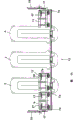
Fig. 1 is a side view with milling train row of three mill stands;
Figure 1A is a run location figure with mill stand of a working roll group and a backing roll group;
Fig. 2-9 shows the vertical view of the different phase of changing a working roll group;
Fig. 9 A is the stand of horizontal locomotive; With
Figure 10 shows the vertical view in " intermediate plate is upward deflected " stage, turns back to the starting position of Fig. 2 simultaneously.
The specific embodiment
In Fig. 1 and 1A, milling train row 1 for example are made of three mill stands 2,3 and 4.Each mill stand 2,3,4 has one respectively and is arranged in the backing roll group 5 of run location and is with the working roll group 6 of the wearing and tearing of assembly parts.Working roll group and backing roll group 5,6 have been removed in Fig. 1, and lay respectively on one first horizontal locomotive 9, second horizontal locomotive 10 and one the 3rd horizontal locomotive 11.Working roll group 6 (or 6a) respectively by two by lower support on the assembly parts go up and lower rolls constitute, (in the not expression in detail of dismounting stage) backing roll group 5 is so same.Provided this starting position 1a in Fig. 1, wherein the roll exchange is carried out on operator's side 1b.The working roll group 6 of wearing and tearing is indicated with a cross symbols respectively among Fig. 2-8 from this side (Fig. 1) with from the top and is not marked cross symbols as new working roll group 6a.
The horizontal locomotive 9,10,11 of independence of the quantity respective numbers of a plurality of and mill stand 2,3,4 is arranged on operator's side 1b, and they admit these new working roll group 6a that sends here from a roll shop 20.6 of the working roll groups of these wearing and tearing roll working cylinder 8 away from by working roll and a locomotive 21 is pulled out.The motion of right laterally locomotive 9,10,11 of travel-driving mechanism that oneself is housed respectively is then unique carrying out to the connection track 14a of roll shop 20, and laterally locomotive 9,10,11 is travelled along rolling direction 13 by guide rail 14 simultaneously.From guide rail 14 to connecting continuing to transport and realizing of track 14a by the slide plate on corresponding assembly parts.Only carry out in the operation that connects on the track 14a by a unique locomotive 21.Laterally locomotive 9,10,11 is by space mechanism 7 controls.Respectively after working roll group 6 backs of wearing and tearing that split out make that by horizontal locomotive 9,10,11 operator's side 1b lets pass, the backing roll group 5 of these wearing and tearing just can be rolled away from and take in the roll shop 20 through crane, refurbish is also taken home, and is loaded in the corresponding mill stand 2,3,4 that disposes again and locking.On the guide rail 14 in 15 the foundation pit 15a of basis laterally the maneuverability of locomotive 9,10,11 guaranteed to be used for the space that splits out or reinstall 12 (also can with reference to figure 9) of backing roll group 5 respectively.
Laterally locomotive 9,10,11 to be changing spacing 2a, 3a, the right side of the working roll group 6 that 4a (when three mill stands) configuration is used to wear and tear half and be used for new working roll group 6a the left side second half.Space mechanism 7 is in the present embodiment by constituting by rotating intermediate plate 7a.Intermediate plate 7a is low weight and thinner, thereby does not need crane to operate.
Figure 2 illustrates the starting position 1a before each mill stand 2,3,4 in addition, wherein laterally locomotive 9,10,11 is regulated by the intermediate plate 7a that swings to level.After this Mo Sun working roll group 6 is transported (Fig. 3).After second half of car, new working roll group 6a is fed in the corresponding mill stand 2,3,4 at cross running.After this working roll group 6 of wearing and tearing is sent to roll shop 20 and goes maintenance.New working roll group 6a is sent back to starting position 1a (Fig. 2), begins new periodic duty then.
Wherein uniqueness is, at the vehicle body of respectively the working roll group 6 of wearing and tearing being moved to corresponding configuration on the 1a of starting position on half, and it is adjusted on the replacing spacing 2a, 3a, 4a of mill stand 2,3,4 fronts-is placed on vehicle body on second half new working roll group 6a-, and thus executed accurate an adjusting.
According to Fig. 3, whole horizontal locomotive 9,10,11 is arranged in order arrangement in the situation that changes intermediate plate 7a over to spacing 2a, 3a, 4a.Laterally pack into position or mill stand of locomotive 9,10,11 mill stand along rolling direction from these qualifications splits out the position and in turn moves out.
According to Fig. 4, all new working roll group 6a are positioned at it to the position of packing into of mill stand 2,3,4, and sail cylinder 8 into and locomotive 21 pushes by working roll, are locked in the mill stand then.
In Fig. 5, new working roll group 6a has been pushed in the mill stand 2,3,4 and has been locked on the run location.Between single moving period, the intermediate plate 7a that forwards level respectively to can repeat accurately to be adjusted on the described spacing between the horizontal locomotive 9,10,11 in the replacing position with a relative adjacent mill stand 2,3,4, wherein, the connecting plate 18 that support definitely the position on the end of guide rail 14 is with remaining gap sealing.Spacing between horizontal locomotive 9,10,11 can turn to or the upright position elimination by intermediate plate 7a and/or connecting plate 18, as shown in Figure 6.
The upright position of intermediate plate 7a and connecting plate 18 provides free space, therefore just produces a space 12 (also referring to Fig. 9 A) in order to change backing roll group 5 respectively in mill stand 2,3,4 fronts by removing horizontal locomotive 9,10,11.Mo Sun backing roll group 5 can be removed and with crane a backing roll group 5 new, that overhauled be sent into again via crane then.
According to Fig. 7, laterally locomotive 9,10,11 arrives on the link position of a locomotive 21 on the relative connection track 14a successively.The working roll group 6 of corresponding wearing and tearing is sent to roll shop 20 and goes, and changes with new working roll group 6a there.
As shown in Figure 8, the working roll group 6 of next wearing and tearing is whenever delivered in the roll shop 20 by locomotive 21, changes and is sent back to a new working roll group 6a again there, and this is what to have settled in Fig. 8.
According to Fig. 9, the second working roll group 6 has been seen off and has been taken back a new working roll group 6a from roll shop 20.Only also having the 3rd working roll group 6 of wearing and tearing should be sent in the roll shop 20 goes.
Represent as Fig. 9 A, empty horizontal locomotive 9,10,11 changes downward or upward at intermediate plate 7a and connecting plate 18 and sails in the stand (horizontal locomotive 11) on a left side stand (laterally locomotive 9,10) and a right under the situation of upright position, wherein intermediate plate 7a changeed down and connecting plate 18 upwards parked, thereby saved the position.Just vacated to be used for other operation in the space 12 of mill stand 3 and 4 fronts thus.
As further finding out from Fig. 9 A, intermediate plate 7a is bearing on the horizontal locomotive 9,10,11 in the movable joint mode separately respectively, and by one on the dolly together the operation piston-cylinder-driving mechanism 17 pneumatic or hydraulic pressure shift to above or shift to below.Such piston-cylinder-driving mechanism 17 is placed on the connecting plate 18, and bilateral ground configuration on the first horizontal locomotive 9, and is configured in the right side unilaterally on the second horizontal locomotive and the 3rd horizontal locomotive 10 and 11.
Laterally locomotive 9,10,11 sails to again on the demolition position of mill stand 2,3,4 fronts according to Figure 10 after loading a new working roll group 6a respectively.Then intermediate plate 7a is thus lifted on the horizontal level, and connecting plate 18 is lowered by on the horizontal level.New working roll group 6a is in working roll group 6 quick the replacings on the ready position for wearing and tearing thus.The present invention also allows the replacing of single wearing and tearing working roll group 6.
Laterally locomotive 9,10,11, be transferred to the intermediate plate 7a of level and can upwards forward in the end of foundation pit 15a level, the position definitely the connecting plate 18 of rotatable support constitute a continuous transitable working face 19 in the horizontal direction.
In Fig. 1,2-5 and 10, on the end that is parallel to the guide rail 14 that rolling direction 13 extends, settled respectively rotatable support that the position determines, and upwards can be adjusted to the connecting plate 18 of upright position, they constitute this working face 19 with intermediate plate 7a.
The reference symbol table
The 1--mill, the 1a-starting position, 1b--operator side, 2-mill stand, 2a-are more Change spacing, the 3-mill stand, 3a-changes spacing, the 4-mill stand, 4a-changes spacing, 5-backing roll group, the working roll group (accompanying drawing: with cross symbols) of 6-wearing and tearing, 6a-is new The working roll group (accompanying drawing: no cross symbols), 7-space mechanism, 7a-can rotating intermediate plates, The 8-working roll rolls/sails into working cylinder away from, the 9-first transverse shifting car, 10-second transverse shifting Car, the space before 11-the 3rd transverse shifting car, 12-mill stand, 13-rolling direction, 14-Guide rail, 14a-joining rails, 15-basis, 15a-foundation pit, 17-piston-cylinder-driving machine Structure, the fixed supported connecting plate in 18-position, the transitable working face of 19-, 20-Roller Machining The workshop, the 21-locomotive.
Claims (13)
1. be used for changing the method for roll stacks (5,6) of the mill stand (2,3,4) of milling train row (1), these milling train row (1) have a plurality of mill stands (2,3,4), they have supporting and working roll group (5,6) respectively, wherein roll stacks supports mutually and goes along axially passing out in the roll shop (20) of working roll group (6) or backing roll group (5) in operator's side (1b) subsequently, and transport back subsequently and the new roll stacks (5 of packing into, 6), it is characterized in that:
These by operator's side (1b) with mill stand (2,3, the independently horizontal locomotive (9 of quantity respective numbers 4), 10, the wearing and tearing working roll group (6) of 11) being transported is delivered in the roll shop (20) by a unique locomotive (21) on a unique connection track (14a) successively, transport new working roll group (6a) then therefrom back, and so that replacing spacing (2a to be arranged, 3a, mode 4a) is placed on mill stand (2,3,4) corresponding laterally locomotive (9 between, 10,11) on, and pass through horizontal locomotive (9 in working roll group (6) back that splits out wearing and tearing respectively, 10,11), make operator's side (1b) release afterwards the backing roll group (5) of these wearing and tearing be transported, and take in the roll shop (20) through crane, keep in repair, transport and reload the mill stand (2 of correspondence configuration back, 3,4) in.
2. by the described method of claim 1, it is characterized in that:
In the starting position (1a) of each mill stand (2,3,4) front, described horizontal locomotive (9,10,11) is adjusted to simultaneously and is changed on the spacing (2a, 3a, 4a), the working roll group (6) of wearing and tearing is sent, moving laterally to vehicle body after second half, new working roll group (6a) is sent into, and the working roll group (6) of wearing and tearing delivered in the roll shop (20), unloads by the sliding panel on the assembly parts by its horizontal locomotive (9,10,11) respectively, and a new working roll group (6a) is transported back in the starting position (1a) again.
3. by the described method of claim 2, it is characterized in that:
In described starting position (1a), the working roll group (6) of described wearing and tearing is pulled to the vehicle body of described corresponding configuration respectively on half, and the new working roll group (6a) that will send here from roll shop (20) with the working roll group of changing the wearing and tearing of spacing (2a, 3a, 4a) distance shift vehicle body onto on second half.
4. by one of claim 1-3 described method, it is characterized in that:
Described horizontal locomotive (9,10,11) is gone up from pack into position or split out on the position of its limited mill stand in rolling direction (13) and is shifted out successively.
5. by one of claim 1-3 described method, it is characterized in that:
At every turn by the intermediate plate (7a) that is turned back to level just can repeat accurately to be adjusted between the horizontal locomotive (9,10,11) described spacing and with respect to the replacing position of adjacent mill stand (2,3,4), and the replacing spacing (2a, 3a, 4a) of regulating like this is under intermediate plate (7a) and/or connecting plate (18) commentaries on classics or can eliminate on the upright position.
6. by one of claim 1-3 described method, it is characterized in that:
By being removed, the horizontal locomotive (9,10,11) of mill stand (2,3,4) front just correspondingly provides a space (12) in order to change backing roll group (5), and wearing and tearing backing roll group (5) seen off via crane, new maintenance backing roll group (5) be admitted to again via crane.
7. by the described method of claim 6, it is characterized in that:
Described space (12) in mill stand (2,3,4) front changing over to and being closed by intermediate plate (7a), and laterally locomotive (9,10,11) moves on to again on this replacing spacing (2a, 3a, 4a).
8. by one of claim 1-3 described method, it is characterized in that:
Empty horizontal locomotive (9,10,11) is moved under by the situation of the intermediate plate (7a) under changeing on the end that is positioned at milling train row (1) and/or the parking spot on the other end and is parked.
9. be used for mill stand (2 at milling train row (1), 3,4) change roll stacks (5 in, 6) device, these milling train row (1) have a plurality of mill stands (2,3,4), they have supporting and working roll group (5 respectively, 6), this device has one and is used for roll stacks (5,6) driving mechanism that laterally splits out or laterally pack into, wherein be parallel to rolling direction (13) shop in (15) puts and is used for horizontal locomotive (9 on the basis, 10,11) guide rail (14) with lead to roll shop (20) be connected track (14a), and described horizontal locomotive is connected with a driving mechanism, it is characterized in that:
Described horizontal locomotive (9,10,11) can be parallel in (15) on the basis rolling direction (13) continuously the spacing determined between going up with mill stand (2,3,4) of the guide rail (14) put of shop move, this spacing can be by controlling by rotating intermediate plate (7a), and have only a connection track (14a) to extend in the roll shop (20) perpendicular to guide rail (14), have only a locomotive (21) operation thereon, on locomotive, can connect respectively or disconnected connection working roll group (6,6a).
10. by the described device of claim 9, it is characterized in that:
Described intermediate plate (7a) can correspondingly make progress and turn round or be adjusted to pivotally vertically or be adjusted to level downwards.
11., it is characterized in that by claim 9 or 10 described devices:
Described intermediate plate (7a) individually is hinged on respectively on the horizontal locomotive (9,10,11), and can be by one in laterally upward piston-cylinder-driving mechanism (17) revolution of movable joint supporting of locomotive (9,10,11).
12., it is characterized in that by claim 9 or 10 described devices:
Described horizontal locomotive (9,10,11) be turned back to the intermediate plate (7a) of level and on the end of a foundation pit (15a), can upwards reach horizontal rotation, the position definitely the connecting plate of rotatable support (18) constitute a continuous transitable working face (19).
13., it is characterized in that by claim 9 or 10 described devices:
Disposed respectively on the end that is parallel to the guide rail (14) that rolling direction (13) extends that the position is determined and the connecting plate (18) of turning supporting, described connecting plate allow in resupinate position horizontal locomotive (9,10,11) additionally move horizontally horizontal locomotive (9,10,11) one of them width at least half.
Applications Claiming Priority (2)
| Application Number | Priority Date | Filing Date | Title |
|---|---|---|---|
| DE102004007831A DE102004007831A1 (en) | 2004-02-18 | 2004-02-18 | Replacing sets of rollers mounted in frames in rolling mill comprises bringing replacement rollers in trucks pulled by single locomotive along frames, worn rollers then being removed and replaced |
| DE102004007831.9 | 2004-02-18 |
Publications (2)
| Publication Number | Publication Date |
|---|---|
| CN1921959A CN1921959A (en) | 2007-02-28 |
| CN100415399C true CN100415399C (en) | 2008-09-03 |
Family
ID=34813472
Family Applications (1)
| Application Number | Title | Priority Date | Filing Date |
|---|---|---|---|
| CNB2005800051464A Expired - Fee Related CN100415399C (en) | 2004-02-18 | 2005-01-21 | Method and device for exchanging sets of rolls in rolling frames of a rolling mill |
Country Status (8)
| Country | Link |
|---|---|
| US (1) | US7698923B2 (en) |
| EP (1) | EP1715967B1 (en) |
| JP (1) | JP4785754B2 (en) |
| CN (1) | CN100415399C (en) |
| DE (2) | DE102004007831A1 (en) |
| RU (1) | RU2363555C2 (en) |
| UA (1) | UA87677C2 (en) |
| WO (1) | WO2005089972A1 (en) |
Families Citing this family (13)
| Publication number | Priority date | Publication date | Assignee | Title |
|---|---|---|---|---|
| FR2893867B1 (en) | 2005-11-25 | 2008-02-15 | Vai Clecim Soc Par Actions Sim | METHOD FOR MANAGING CYLINDERS IN A ROLLING WORKSHOP AND INSTALLATION FOR ITS IMPLEMENTATION |
| JP5344928B2 (en) | 2006-01-09 | 2013-11-20 | エス・エム・エス・ジーマーク・アクチエンゲゼルシャフト | Method and apparatus for operating and transporting work rolls and backup rolls |
| DE102007061027A1 (en) | 2006-12-28 | 2008-07-03 | Sms Demag Ag | Method for deploying set of working rolls from frame with locomotive arranged in roll changing hole under plant floor, involves coupling used set of working rolls on locomotive |
| DE102007049669A1 (en) * | 2007-10-17 | 2009-04-23 | Sms Demag Ag | Lock device and method for opening the lock device |
| EP2259881B1 (en) * | 2008-04-11 | 2013-05-29 | Siemens Vai Metals Technologies SAS | Plant for the reversible rolling of steel strip |
| DE102009037665A1 (en) | 2009-08-14 | 2011-02-17 | Sms Siemag Ag | Device for handling and / or transporting rolls of a roll stand |
| CN102921737A (en) * | 2012-11-26 | 2013-02-13 | 青岛润丰铝箔有限公司 | Disassembly and assembly equipment for bearing box of working roll of aluminum foil mill |
| DE102013224633A1 (en) * | 2013-01-14 | 2014-07-17 | Sms Siemag Ag | Casting rolling mill and method for removing and installing rolls in a reduction stand of the casting rolling mill |
| WO2015050823A2 (en) * | 2013-10-02 | 2015-04-09 | Fives Bronx, Inc. | Roll change apparatus |
| CN104259365B (en) * | 2014-08-28 | 2016-04-27 | 太原重工股份有限公司 | Forging press anvil storehouse |
| RU182013U1 (en) * | 2017-05-23 | 2018-07-31 | Федеральное государственное бюджетное образовательное учреждение высшего образования "Липецкий государственный технический университет" (ЛГТУ) | A device for maintaining the spindle shafts of the stand of the leveling machine during their installation and dismantling |
| CN109304588B (en) * | 2018-09-14 | 2021-01-29 | 金川集团股份有限公司 | Method for replacing and installing split large gear of ball mill |
| CN111618090A (en) * | 2020-04-02 | 2020-09-04 | 中冶华天工程技术有限公司 | Roller-changing transverse device for heavy-load H-shaped steel and cloud-rail tandem rolling mill roller system |
Citations (5)
| Publication number | Priority date | Publication date | Assignee | Title |
|---|---|---|---|---|
| JPS56154208A (en) * | 1980-04-28 | 1981-11-28 | Hitachi Ltd | Replacing apparatus for roll of rolling mill |
| US4771626A (en) * | 1986-03-14 | 1988-09-20 | Nippon Steel Corporation | Apparatus for roll-changing |
| CN1091061A (en) * | 1993-02-15 | 1994-08-24 | 日铁建材工业株式会社 | Standby more changing device of roll and insert integral roll |
| CN1358585A (en) * | 2000-12-13 | 2002-07-17 | 三菱重工业株式会社 | Roller changing equipment and method for rolling machine |
| WO2003015949A1 (en) * | 2001-08-06 | 2003-02-27 | Sms Demag Ag | Device for changing the work rolls and the back-up rolls of a strip mill |
Family Cites Families (6)
| Publication number | Priority date | Publication date | Assignee | Title |
|---|---|---|---|---|
| GB1153228A (en) * | 1967-01-25 | 1969-05-29 | Loewy Robertson Eng Co Ltd | Improvements in and relating to Roll-Changing Devices for Horizontal Rolling Mills |
| JPS5424710B1 (en) * | 1975-01-11 | 1979-08-23 | ||
| JPS52123959A (en) * | 1976-04-12 | 1977-10-18 | Ishikawajima Harima Heavy Ind | Roll combination changer |
| JPS5364651A (en) * | 1976-11-22 | 1978-06-09 | Ishikawajima Harima Heavy Ind | Rolling mill roll rearrange device |
| FI81033C (en) * | 1988-12-22 | 1990-09-10 | Rautaruukki Oy | Method and apparatus for exchanging work rolls in rolling mills |
| JP3042099B2 (en) * | 1991-10-24 | 2000-05-15 | 石川島播磨重工業株式会社 | Roll shop and bogie for rolling rolls |
-
2004
- 2004-02-18 DE DE102004007831A patent/DE102004007831A1/en not_active Withdrawn
-
2005
- 2005-01-21 RU RU2006133335/02A patent/RU2363555C2/en not_active IP Right Cessation
- 2005-01-21 UA UAA200609919A patent/UA87677C2/en unknown
- 2005-01-21 CN CNB2005800051464A patent/CN100415399C/en not_active Expired - Fee Related
- 2005-01-21 US US10/584,431 patent/US7698923B2/en not_active Expired - Fee Related
- 2005-01-21 EP EP05706957A patent/EP1715967B1/en not_active Not-in-force
- 2005-01-21 JP JP2006553467A patent/JP4785754B2/en not_active Expired - Fee Related
- 2005-01-21 WO PCT/EP2005/000593 patent/WO2005089972A1/en active IP Right Grant
- 2005-01-21 DE DE502005002039T patent/DE502005002039D1/en active Active
Patent Citations (5)
| Publication number | Priority date | Publication date | Assignee | Title |
|---|---|---|---|---|
| JPS56154208A (en) * | 1980-04-28 | 1981-11-28 | Hitachi Ltd | Replacing apparatus for roll of rolling mill |
| US4771626A (en) * | 1986-03-14 | 1988-09-20 | Nippon Steel Corporation | Apparatus for roll-changing |
| CN1091061A (en) * | 1993-02-15 | 1994-08-24 | 日铁建材工业株式会社 | Standby more changing device of roll and insert integral roll |
| CN1358585A (en) * | 2000-12-13 | 2002-07-17 | 三菱重工业株式会社 | Roller changing equipment and method for rolling machine |
| WO2003015949A1 (en) * | 2001-08-06 | 2003-02-27 | Sms Demag Ag | Device for changing the work rolls and the back-up rolls of a strip mill |
Also Published As
| Publication number | Publication date |
|---|---|
| CN1921959A (en) | 2007-02-28 |
| JP2007522943A (en) | 2007-08-16 |
| US20090013745A1 (en) | 2009-01-15 |
| UA87677C2 (en) | 2009-08-10 |
| DE102004007831A1 (en) | 2005-09-01 |
| JP4785754B2 (en) | 2011-10-05 |
| DE502005002039D1 (en) | 2008-01-03 |
| WO2005089972A1 (en) | 2005-09-29 |
| RU2363555C2 (en) | 2009-08-10 |
| EP1715967B1 (en) | 2007-11-21 |
| RU2006133335A (en) | 2008-04-10 |
| EP1715967A1 (en) | 2006-11-02 |
| US7698923B2 (en) | 2010-04-20 |
Similar Documents
| Publication | Publication Date | Title |
|---|---|---|
| CN100415399C (en) | Method and device for exchanging sets of rolls in rolling frames of a rolling mill | |
| KR101102907B1 (en) | Method and device for changing rolls | |
| JP4996617B2 (en) | Method for managing rolls at rolling mill plants and equipment for implementing the method | |
| JPH07290691A (en) | Printing press | |
| CN101360570B (en) | Device for handling/transporting rolls | |
| CN100556548C (en) | The security system that is used for roller mill | |
| CN2829928Y (en) | Fast roller displacing appts, for six-roller rolling mill | |
| CN101966927A (en) | Vertical conveying system for core winding frame | |
| JP2007516858A (en) | Printing press | |
| US7363793B2 (en) | Rolling mill comprising means for exchanging the rolls | |
| CN110523779B (en) | Device and method for replacing stand roller of reversible rolling mill | |
| CN103781563B (en) | Driving roller more exchange device for the driver of milling equipment | |
| US20060150702A1 (en) | Rolling mill with support plates | |
| CN102869512A (en) | Screen printer | |
| CN101352731A (en) | Lower back-up roll extractor of cluster roll | |
| CN116262323A (en) | Continuous automatic feeding unit for metal bar production and processing | |
| GB2094684A (en) | Rolling mills |
Legal Events
| Date | Code | Title | Description |
|---|---|---|---|
| C06 | Publication | ||
| PB01 | Publication | ||
| C10 | Entry into substantive examination | ||
| SE01 | Entry into force of request for substantive examination | ||
| C14 | Grant of patent or utility model | ||
| GR01 | Patent grant | ||
| C17 | Cessation of patent right | ||
| CF01 | Termination of patent right due to non-payment of annual fee |
Granted publication date: 20080903 Termination date: 20120121 |