CN101966927A - Vertical conveying system for core winding frame - Google Patents
Vertical conveying system for core winding frame Download PDFInfo
- Publication number
- CN101966927A CN101966927A CN2010102956083A CN201010295608A CN101966927A CN 101966927 A CN101966927 A CN 101966927A CN 2010102956083 A CN2010102956083 A CN 2010102956083A CN 201010295608 A CN201010295608 A CN 201010295608A CN 101966927 A CN101966927 A CN 101966927A
- Authority
- CN
- China
- Prior art keywords
- volume core
- core frame
- bed
- roller machine
- delivery system
- Prior art date
- Legal status (The legal status is an assumption and is not a legal conclusion. Google has not performed a legal analysis and makes no representation as to the accuracy of the status listed.)
- Granted
Links
Images


Landscapes
- Winding, Rewinding, Material Storage Devices (AREA)
Abstract
The invention provides a vertical conveying system for a core winding frame, which comprises the core winding frame, a lifting roller machine, a turning roller machine, a conveying roller machine and a rotating roller machine, wherein, the core winding frame bears coils; the lifting roller machine clamps and lifts the core winding frame to a coil collecting drum for bearing the coils and then returns and delivers the core winding frame; the turning roller machine turns over the delivered core winding frame to a horizontal position; the conveying roller machine horizontally conveys the core winding frame; and the rotating roller machine horizontally rotates 90 degrees. In the invention, the coils are born by the equipment with simple structures, thus being easier to control, lowering fault rate of the equipment and being more beneficial to normal operation of the whole process; in addition, the conveying roller machine is arranged between the lifting roller machine and the turning roller machine for conveying the core winding frame carrying the coils, which avoids direct contact between the coil surfaces and the conveying roller machine so as to stably control the surface quality of the coils. In addition, the conveying system of the invention is equipped with the rotating roller machine for changing the delivery direction of the core winding frame, which greatly saves plant space on the premise of guaranteeing sufficient cooling sections.
Description
Technical field
The present invention relates to iron and steel, field of metallurgy, relate in particular to a kind of conveying technology.
Background technology
In the wire rod rolling project of existing steelworks, normally used technological process as shown in Figure 1:
At first, will send into heating furnace high-temperature as blank material such as iron ore, steel billets and handle and begin to take shape slab; Then successively to these slabs carry out roughing, in roll, rolling processing links such as pre-finish rolling, finish rolling, form coiling of moulding; Next, coiling of these moulding sent into the volume air cooling system that looses it is carried out air-cooled cooling processing, make its temperature obtain part and fall after rise, for 2 tons coil (specification is generally Φ 1250 * Φ 850L=3000mm), the temperature after the air-cooled processing is about 600 degrees centigrade.Subsequently these are coiled and deliver to collection volume station, at collection volume station, the equipment of main operation is both arms mandrel system and fortune volume dolly.Both arms mandrel system will be arranged in coiling of Ji Juantongchu and be undertaken in mandrel, and this mandrel is turn to level, will coil then to eject, and be lifted on the fortune volume dolly by suspender, and fortune volume dolly carries this coils and transport to P/F line cooling system; At P/F line cooling system, coil further and cooled off, be admitted to warehouse for finished product after weighing.
Above-mentioned both arms mandrel system is that a cover integrates equipment mechanical, electric, fluid control, its complex structure, integrated level is than higher, in actual use, fault rate is also than higher, when it goes wrong,, can cause the whole technology can't normal operation because its integrated level gives fast than higher that maintenance brings difficulty.And, change constantly and coil the mandrel that contacts, also relatively more difficult.
In addition, certainly after coiling the mandrel that leaves both arms mandrel system in the above-mentioned technological process, will the follow-up equipment of direct contact, the surface that can wear and tear and coil like this, thereby influence the presentation quality of coiling greatly, especially when mill milling high-quality light face is rolled up, use the equipment in the above-mentioned technology, can't stablize the surface quality that control is coiled.
In addition, coil temperature still about 600 degrees centigrade after the air-cooled processing, this requires on the subsequent technique enough cooling sections to be arranged, because P/F line cooling system can only arrange that this can take more factory building space undoubtedly according to length direction.
Summary of the invention
The purpose of this invention is to provide a kind of vertical volume core frame delivery system, this invention is simple in structure, is more prone in the control realize, thereby makes equipment failure rate reduce greatly, is beneficial to the normal operation of whole technology more.
The objective of the invention is to be achieved through the following technical solutions:
The invention provides a kind of vertical volume core frame delivery system, it comprises:
Be used to carry the volume core frame of coiling;
Clamp described volume core frame, it is lifted to Ji Juantongchu accepts and coil and fall the lifting rolling machine that transfers out described volume core frame after rise;
Bed is rolled in the upset that the volume core frame of exporting is turn to level.
Wherein, preferred, described volume core frame comprises:
Base; Be arranged on the volume core on the described base; Described volume core top is provided with the suspension hook ring; Be arranged on the supporting plate of described base bottom.
Wherein, preferred, described lifting rolling machine comprises:
Clamp the fixing device of described volume core frame;
Be arranged on the feedway of the volume core frame bottom that described fixing device clamps;
Drive the jacking system of described fixing device and described feedway lifting.
Wherein, preferred, described upset is rolled bed and is comprised:
Clamp the fixing device of described volume core frame;
Be arranged on the conveying bed of the volume core frame bottom that described fixing device clamps;
Outside frame bonded assembly turning rack with described fixing device and conveying bed;
Be arranged on the fix shaft of described turning rack one side;
Drive the overturning drive device of described turning rack around described fix shaft rotation.
Wherein, preferred, described vertical volume core frame delivery system also comprises:
The transportation rolling-bed of described volume core frame carried in carrying; Describedly transportation rolling-bedly be arranged on described lifting rolling machine and described upset is rolled between the bed.
Wherein, preferred, described transportation rolling-bed comprising:
The a plurality of wheel shafts that be arranged in parallel,
Drive the driver element that described wheel shaft is synchronized with the movement.
Wherein, preferred, described transportation rolling-bedly also comprise:
Detect the detecting unit of the position of the described volume core frame of carrying on the described wheel shaft;
Control the control unit of described driver element operation according to the location information of described detecting unit feedback.
Wherein, preferred, described vertical volume core frame delivery system also comprises:
Bed is rolled in the rotation that is used to change described volume core frame outbound course; Described rotation roll the bed be arranged on described lifting rolling machine and described transportation rolling-bed between, perhaps be arranged on a plurality of transportation rolling-bed between, perhaps be arranged on described transportation rolling-bed and described upset and roll between the bed.
Wherein, preferred, described rotation is rolled bed and is comprised:
Revolution is supported; Rotating machine; Rotating machine connects miniature gears by motor shaft, and miniature gears supports by gear cluster and revolution and goes up the big gear wheel engagement that is provided with;
Be arranged on the conveying roller on the revolution support outside frame; Drive movable motor and conveyer chain that described conveying roller is synchronized with the movement.
Wherein, preferred, described fixing device comprises:
Fixed mount; Movable stand; One end is arranged on the described fixed mount, and the other end is arranged on the actuating device of the described movable stand motion of driving on the described movable stand.
As seen from the above technical solution provided by the invention, the present invention adopts simple lifting rolling machine, these equipment simple in structure of volume core frame to accept and coil, having replaced original both arms mandrel system to accept coils, make to control and be more prone to realize, equipment failure rate reduces greatly, is beneficial to the normal operation of whole technology more; And, constantly in a single day damage with coiling the volume core frame that contacts, change also more convenient.
In addition, the present invention is provided with transportation rolling-bed the conveying and carries the volume core frame of coiling by rolling in described lifting rolling machine and described upset between the bed, like this in transportation, be that volume core frame contacts with transportation rolling-bed, avoided coiling the surface with transportation rolling-bed between direct contact, control the surface quality of coiling thereby can stablize.
In addition, the present invention is provided with the rotation that is used to change described volume core frame outbound course and rolls bed, like this under the prerequisite that guarantees enough cooling sections, can arrange more transportation rolling-bedly in factory building more easily, has saved the factory building space greatly.
Description of drawings
The conventional process flow figure that Fig. 1 provides for background technology;
The vertical volume core frame delivery system structural representation of Fig. 2 for providing in the first embodiment of the invention;
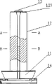
The front view of the volume core frame that provides in the first embodiment of the invention is provided Fig. 3;
The A-A section drawing of the volume core frame that provides in the first embodiment of the invention is provided Fig. 4;
The B-B section drawing of the volume core frame that provides in the first embodiment of the invention is provided Fig. 5;
The structural representation of the lifting rolling machine that provides in the first embodiment of the invention is provided Fig. 6;
The transportation rolling-bed front view of Fig. 7 for providing in the first embodiment of the invention;
The transportation rolling-bed birds-eye view of Fig. 8 for providing in the first embodiment of the invention;
The transportation rolling-bed C-C cutaway view of Fig. 9 for providing in the first embodiment of the invention;
The structural representation of bed is provided for the rotation that provides in the first embodiment of the invention Figure 10;
The structural representation of bed is provided for the upset that provides in the first embodiment of the invention Figure 11;
Scheme drawing when Figure 12 rolls bed and will roll up the core frame and turn to level for the upset that provides in the first embodiment of the invention.
The specific embodiment
Below in conjunction with accompanying drawing specific embodiment provided by the invention is described in detail.
First embodiment provided by the invention is a kind of vertical volume core frame delivery system, and its structure comprises as shown in Figure 2: volume core frame 1, lifting rolling machine 2, transportation rolling-bed 3, bed 4 is rolled in rotation, bed 5 is rolled in upset.
Lifting rolling machine 2 will be rolled up core frame 1 and clamp, and it is given rise to Ji Juantongchu accept and coil, and fall after rise then and will unclamp volume core frame 1, and flow to transportation rolling-bed 3; Transportation rolling-bed 3 are carrying the volume core frame of coiling 1 are being housed, and run in the time of need turning to, and volume core frame 1 is flowed to rotation roll bed 4 and realize turning to of volume core framves 1; Finally roll bed 5 and will roll up core frame 1 and turn to level, hold up by the volume of the fortune on subsequent technique dolly afterwards and roll up coiling and sending on the core frame 1 by upset.
Above-mentioned volume core frame 1 is used for vertically holding a kind of weldment of coiling.Its structure comprises shown in Fig. 3,4,5: base 11, the top that is arranged on volume core 12 on the described base 11, volume core 12 are connected with suspension hook ring 13, are arranged on the supporting plate 14 of described base 11 bottoms.Wherein, volume core 12 comprises pillar stiffener 121, pillar stiffener 121 lower ends are fixedly mounted on the base on 11, be welded with floor 122 respectively on the four direction all around of pillar stiffener 121, the top of four floors 122 is welded with connecting panel 123, and connecting panel 123 is connected with the suspension hook ring 13 at the top that is arranged on volume core 12 by attaching partss such as bolts.Because directly in transportation rolling-bed 3 contacts, the wearing and tearing that are subjected to are more some more for supporting plate 13, other parts of life cycle relative volume core frame are shorter, change supporting plate 13 for convenience, and supporting plate 13 is by being bolted to the bottom of base 11.
Above-mentioned lifting rolling machine 2 is arranged on collection reel bottom, and radical function is with 1 clamping of volume core frame, and it is given rise to Ji Juantongchu accepts and coil, receive coil after, fall after rise to former height, unclamp volume core frame 1, and will carry the volume core frame of coiling 1 and flow to transportation rolling-bed 3.Volume core frame 1 is being with to coil and is being left, and it enters next circulation, continues to receive the next one at Ji Juantongchu and coils.
The structure of lifting rolling machine 2 comprises as shown in Figure 6: the jacking system 23 that clamps the fixing device 21 of described volume core frame 1, the feedway 22 that is arranged on described fixing device 21 bottoms, the described fixing device 21 of driving and 22 liftings of described feedway.
Wherein, above-mentioned fixing device 21 comprises: fixed mount; Movable stand; One end is arranged on the described fixed mount, and the other end is arranged on the actuating device of the described movable stand motion of driving on the described movable stand.This actuating device can be that (expansion link one end of cylinder is connected in movable stand for as shown in Figure 6 cylinder, the cylinder body of cylinder is fixed on the fixed mount), it also can be hydraulic actuating cylinder, also can realize clamping or unclamping the action of volume core frame 1 by other physical construction, as: motor-driven gear, tooth bar and movable stand are fixed, and realize that by the rack-and-gear engagement movable stand moves.
Above-mentioned feedway 22, can with fixing device 21 shared frameworks, be arranged on the bottom of the described volume core frame 1 that described fixing device 21 clamped.Its function is: after fixing device 21 unclamps, and carrying volume core frame 1, and should roll up core frame 1 and transfer out.This feedway 22 comprises: a plurality of conveying rollers drive motor and conveyer chain that these a plurality of conveying rollers are synchronized with the movement.
Jacking system 23 is arranged on the bottom of above-mentioned feedway 22, comprises lifting mechanism and driver element, and the driver element in the diagram is the hydraulic actuating cylinder that is obliquely installed, and its cylinder body is fixed on the framework of lifting rolling machine 2, and an end of its expansion link is connected in lifting mechanism.Lifting mechanism in the diagram can certainly be a vertical conveyor for folded formula lifting mechanism.
Above-mentioned transportation rolling-bed 3 are arranged on lifting rolling machine 2 and upset rolls between the bed 5, its function is that volume core frame 1 is carried in carrying, transportation rolling-bed 3 is transportation rolling-bed the most commonly used with three and six, sometimes because the needs of spatial destribution are also used diaxon and four, five etc., preferentially select for use three and six to roll bed in principle, transportation rolling-bedly can independently put down 1, six on a volume core frame and can independently put down two volume core framves 1 because of three, and wasting space not also can be saved cost.With three transportation rolling-bed be example, transportation rolling-bed 3 structure such as Fig. 7, Fig. 8 and shown in Figure 9 comprise:
The wheel shaft 31 that be arranged in parallel; Drive the driver element 32 that described wheel shaft is synchronized with the movement, this driver element comprises motor and conveyer chain; Detect the detecting unit 33 of the position of the described volume core frame of carrying on the described wheel shaft 31 1; Control the control unit 34 (not shown, as can long-rangely to be placed in the control housing) of described motor operation according to the location information of described detecting unit feedback.
Above-mentioned detecting unit 33 can be arranged on a side of volume core frame 1 landline, be transferred in the process at volume core frame 1, the light of detecting unit 33 can be blocked, will send impulse singla this moment, when the light of detecting unit 33 no longer is blocked, can send impulse singla this moment once more, and twice impulse singla sends control unit 34 to, and control unit 34 will stopping and working according to this impulse singla control motor 32.
For the landline that guarantees to roll up core frame 1 sideslip not, also be provided with centre pilot track 35 in this frame mid portion of transportation rolling-bed 3.
The flex point place that bed 4 is arranged on the vertical volume core of every cover frame system is rolled in above-mentioned rotation, it can be arranged between lifting rolling machine 2 and transportation rolling-bed 3, also can be arranged between a plurality of transportation rolling-bed 3, also can be arranged on transportation rolling-bed 3 and upset roll the bed 5 between, decide according to vertical volume core frame system deployment scenarios needs usually.The effect that bed 4 is rolled in rotation is the outbound course that changes described volume core frame 1, changes 90 degree usually, according to vertical volume core frame system deployment scenarios, needs cw to change 90 degree sometimes, needs conter clockwise to change 90 degree sometimes.
Rotation is rolled bed 4 structure as shown in figure 10, comprising:
Revolution supports 41; Rotating machine 42; Rotating machine 42 connects miniature gears 40 by motor shaft, and miniature gears 40 supports the big gear wheel engagement that is provided with on 41 by gear cluster and revolution;
Support the fixing conveying bed of 41 outside framves with revolution, described conveying bed is provided with conveying roller 43; Drive movable motor 44 and conveyer chain that described conveying roller 43 is synchronized with the movement.
The principle of work of bed 4 is rolled in rotation: rotating machine 42 runnings, and the running of driven gear group realizes carrying bed to rotate 90 degree, after rotational angle put in place, movable motor 44 drove the conveying roller of carrying on the bed 43, and conveying roller 43 rotates, make volume core frame 1 leave rotation and roll bed 4, enter next transportation rolling-bed 3.
Bed 5 main realizations are rolled in above-mentioned upset, and will to roll up that core frame 1 overturns by vertical direction be horizontal direction, because temperature is a lot of than the reduction of lifting rolling machine 2 places to coil this moment, difference according to rolling different steel and climatic conditions, this moment, temperature was generally between 200-300 degree (Celsius temperature), after will rolling up core frame 1 and becoming horizontal direction, fortune volume dolly will roll up the picking-up of coiling on the core frame 1, be suspended on the P/F travel line suspender, thereby realization be coiled by vertical volume core frame system and is transported to transmission on the P/F travel line.
Upset is rolled bed 5 structure as shown in figure 11, comprising: the fixing device 21 that clamps described volume core frame 1; Be arranged on volume core frame 1 bottom that described fixing device 21 is clamped, carry bed 51, carry bed 51 to be provided with conveying roller with the outside frame bonded assembly of described fixing device 21; Drive movable motor and conveyer chain that described conveying roller is synchronized with the movement; Outside frame bonded assembly turning rack 52 with described fixing device 21; Be arranged on the fix shaft 53 of described turning rack 52 1 sides; Drive the overturning drive device 54 of turning rack 52 around described fix shaft 53 rotations.The concrete structure of fixing device 21 and above-mentioned associated description are identical, no longer elaborate here.Overturning drive device 54 is hydraulic actuating cylinders in the diagram, can certainly be not limited to this, also can realize by cylinder etc.
Bed 5 basic functional principle is rolled in upset: coil when moving to upset and rolling bed 5 when volume core frame 1 carries, the movable motor that rolls on the bed shuts down, fixing device 21 clamps volume core frame 1, the hydraulic actuating cylinder of overturning drive device 54 will be carried together jack-up 90 degree of bed 51 and volume core frame, to roll up core frame 1 and carry bed 51 to turn over and turn 90 degrees, as shown in figure 11, provided and to have rolled up core frame 1 and carry bed 51 to turn to the signal of level attitude, this luck volume dolly begins action, will coil from volume core frame 1 to hold up, and takes away, be transported on the suspender above the P/F line cooling system, the hydraulic actuating cylinder oil return of overturning drive device 54 will be rolled up core frame 1 and be put again and get back to vertical position, and fixing device 21 unclamps, movable motor starts, volume core frame 1 leaves upset and rolls bed 5, and next volume core frame 1 enters upset and rolls bed 5, and bed 5 next circulation of beginning are rolled in upset.
Above-mentioned first embodiment is provided with transportation rolling-bed 3 and carries and carry the volume core frame of coiling 1 by rolling in described lifting rolling machine 2 and described upset between the bed 5, like this in transportation, be that volume core frame 1 contacts with transportation rolling-bed 3, avoid coiling surface and the direct contact between transportation rolling-bed 3, thereby can stablize the surface quality that control is coiled.And this first embodiment also is provided with the rotation that is used to change described volume core frame outbound course and rolls bed 4, like this under the prerequisite that guarantees enough cooling sections, can arrange more transportation rolling-bedly 3 in factory building more easily, has saved the factory building space greatly.
Second embodiment provided by the invention is another kind of vertical volume core frame delivery system, and its difference part than first embodiment is, does not rotate among this second embodiment and rolls bed 4.This second embodiment can be applied in factory building length can be satisfied under the situation of coiling cooling.Other device among this second embodiment is identical with the relevant apparatus among first embodiment, is not described in detail here.
This second embodiment is provided with transportation rolling-bed 3 and carries and carry the volume core frame of coiling 1 by rolling in described lifting rolling machine 2 and described upset between the bed 5, like this in transportation, be that volume core frame 1 contacts with transportation rolling-bed 3, avoid coiling surface and the direct contact between transportation rolling-bed 3, thereby can stablize the surface quality that control is coiled.
The 3rd embodiment provided by the invention is the third vertical volume core frame delivery system, its difference part than first embodiment is, be not provided with among the 3rd embodiment transportation rolling-bed 3 and rotation roll the bed 4, the 3rd embodiment can be applied in and substitute traditional both arms mandrel system on original processing line, because the both arms mandrel system architecture that the 3rd embodiment is more traditional is simple, operate also than being easier to,, be beneficial to the normal operation of whole technology more so equipment failure rate reduces greatly; And, constantly in a single day damage with coiling the volume core frame 1 that contacts, change also more convenient.
The above; only for the preferable specific embodiment of the present invention, but protection scope of the present invention is not limited thereto, and anyly is familiar with those skilled in the art in the technical scope that the present invention discloses; the variation that can expect easily or replacement all should be encompassed within protection scope of the present invention.Therefore, protection scope of the present invention should be as the criterion with the protection domain of claim.
Claims (10)
1. a vertical volume core frame delivery system is characterized in that, described vertical volume core frame delivery system comprises:
Be used to carry the volume core frame of coiling (1);
Clamp described volume core frame (1), it is lifted to Ji Juantongchu accepts and coil and fall the lifting rolling machine (2) that transfers out described volume core frame (1) after rise;
Bed (5) is rolled in the upset that the volume core frame of exporting (1) is turn to level.
2. vertical volume core frame delivery system according to claim 1 is characterized in that described volume core frame (1) comprising:
Base (11); Be arranged on the volume core (12) on the described base; Described volume core (12) top is provided with suspension hook ring (13); Be arranged on the supporting plate (14) of described base bottom.
3. vertical volume core frame delivery system according to claim 1 is characterized in that described lifting rolling machine (2) comprising:
Clamp the fixing device (21) of described volume core frame (1);
Be arranged on the feedway (22) of volume core frame (1) bottom that described fixing device (21) clamped;
Drive the jacking system (23) of described fixing device (21) and described feedway (22) lifting.
4. vertical volume core frame delivery system according to claim 1 is characterized in that, described upset is rolled bed (5) and being comprised:
Clamp the fixing device (21) of described volume core frame (1);
Be arranged on the conveying bed (51) of volume core frame (1) bottom that described fixing device (21) clamped;
Outside frame bonded assembly turning rack (52) with described fixing device (21) and conveying bed (51);
Be arranged on the fix shaft (53) of described turning rack one side;
Drive the overturning drive device (54) of described turning rack (52) around described fix shaft (53) rotation.
5. according to any described vertical volume core frame delivery system of claim 1 to 4, it is characterized in that described vertical volume core frame delivery system also comprises:
Transportation rolling-bed (3) of described volume core frame (1) are carried in carrying; Described transportation rolling-bed (3) are arranged on described lifting rolling machine (2) and described upset is rolled between the bed (5).
6. vertical volume core frame delivery system according to claim 5 is characterized in that described transportation rolling-bed (3) comprising:
The a plurality of wheel shafts (31) that be arranged in parallel,
Drive the driver element (32) that described wheel shaft (31) is synchronized with the movement.
7. vertical volume core frame delivery system according to claim 6 is characterized in that described transportation rolling-bed (3) also comprise:
Detect described wheel shaft (31) and go up the detecting unit (33) of the position of the described volume core frame of carrying (1);
Control the control unit (34) of described driver element (32) operation according to the location information of described detecting unit (33) feedback.
8. vertical volume core frame delivery system according to claim 5 is characterized in that, described vertical volume core frame delivery system also comprises:
Bed (4) is rolled in the rotation that is used to change described volume core frame outbound course; Described rotation is rolled bed (4) and is arranged between described lifting rolling machine (2) and described transportation rolling-bed (3), perhaps is arranged between a plurality of transportation rolling-bed (3), perhaps is arranged on described transportation rolling-bed (3) and described upset and rolls between the bed (5).
9. vertical volume core frame delivery system according to claim 8 is characterized in that, described rotation is rolled bed (4) and being comprised:
(41) are supported in revolution; Rotating machine (42); Rotating machine (42) connects miniature gears by motor shaft, and miniature gears supports (41) by gear cluster and revolution and goes up the big gear wheel engagement that is provided with;
Be arranged on the conveying roller (43) on revolution support (41) outside frame; Drive movable motor (44) and conveyer chain that described conveying roller (43) is synchronized with the movement.
10. according to claim 3 or 4 described vertical volume core frame delivery systems, it is characterized in that described fixing device (21) comprising:
Fixed mount; Movable stand; One end is arranged on the described fixed mount, and the other end is arranged on the actuating device of the described movable stand motion of driving on the described movable stand.
Priority Applications (1)
| Application Number | Priority Date | Filing Date | Title |
|---|---|---|---|
| CN 201010295608 CN101966927B (en) | 2010-09-29 | 2010-09-29 | Vertical conveying system for core winding frame |
Applications Claiming Priority (1)
| Application Number | Priority Date | Filing Date | Title |
|---|---|---|---|
| CN 201010295608 CN101966927B (en) | 2010-09-29 | 2010-09-29 | Vertical conveying system for core winding frame |
Publications (2)
| Publication Number | Publication Date |
|---|---|
| CN101966927A true CN101966927A (en) | 2011-02-09 |
| CN101966927B CN101966927B (en) | 2012-12-26 |
Family
ID=43546170
Family Applications (1)
| Application Number | Title | Priority Date | Filing Date |
|---|---|---|---|
| CN 201010295608 Active CN101966927B (en) | 2010-09-29 | 2010-09-29 | Vertical conveying system for core winding frame |
Country Status (1)
| Country | Link |
|---|---|
| CN (1) | CN101966927B (en) |
Cited By (8)
| Publication number | Priority date | Publication date | Assignee | Title |
|---|---|---|---|---|
| CN102602677A (en) * | 2012-03-07 | 2012-07-25 | 常州市联通液压机械有限公司 | Circularly conveying flow line |
| CN104016280A (en) * | 2014-04-03 | 2014-09-03 | 青岛雷霆重工股份有限公司 | Wire lifting and transferring device |
| CN104624673A (en) * | 2013-11-08 | 2015-05-20 | 安阳合力创科冶金新技术研发股份有限公司 | Vertical wire rod feeding system |
| CN105242651A (en) * | 2015-10-16 | 2016-01-13 | 北京金自天正智能控制股份有限公司 | Slow cooling line rotation apparatus and automatic control method thereof |
| CN105836378A (en) * | 2016-06-08 | 2016-08-10 | 承德金龙输送机制造有限公司 | Power module power and free type conveying system |
| CN111530968A (en) * | 2020-05-08 | 2020-08-14 | 青岛雷霆重工股份有限公司 | Roller way type walking core winding frame |
| CN112139264A (en) * | 2020-08-20 | 2020-12-29 | 青岛雷霆重工股份有限公司 | Conveying and transferring system for wire rod coils |
| CN115072299A (en) * | 2022-07-07 | 2022-09-20 | 慈溪市中创自动化科技有限公司 | Automatic loading and unloading system of lasso triaxial |
Citations (2)
| Publication number | Priority date | Publication date | Assignee | Title |
|---|---|---|---|---|
| JPH0648562A (en) * | 1992-04-24 | 1994-02-22 | Sms Schloeman Siemag Ag | Device for transportation of rolled material which is wound around ring in reeling area |
| CN2239845Y (en) * | 1994-09-30 | 1996-11-13 | 北京科技大学 | Device for producing cold-rolled ribbed reinforcing bar |
-
2010
- 2010-09-29 CN CN 201010295608 patent/CN101966927B/en active Active
Patent Citations (2)
| Publication number | Priority date | Publication date | Assignee | Title |
|---|---|---|---|---|
| JPH0648562A (en) * | 1992-04-24 | 1994-02-22 | Sms Schloeman Siemag Ag | Device for transportation of rolled material which is wound around ring in reeling area |
| CN2239845Y (en) * | 1994-09-30 | 1996-11-13 | 北京科技大学 | Device for producing cold-rolled ribbed reinforcing bar |
Cited By (14)
| Publication number | Priority date | Publication date | Assignee | Title |
|---|---|---|---|---|
| CN102602677A (en) * | 2012-03-07 | 2012-07-25 | 常州市联通液压机械有限公司 | Circularly conveying flow line |
| CN104624673B (en) * | 2013-11-08 | 2016-08-17 | 安阳合力创科冶金新技术股份有限公司 | Wire rod vertical feeding system |
| CN104624673A (en) * | 2013-11-08 | 2015-05-20 | 安阳合力创科冶金新技术研发股份有限公司 | Vertical wire rod feeding system |
| CN104016280A (en) * | 2014-04-03 | 2014-09-03 | 青岛雷霆重工股份有限公司 | Wire lifting and transferring device |
| CN105242651B (en) * | 2015-10-16 | 2017-12-05 | 北京金自天正智能控制股份有限公司 | A kind of slow cooling line rotating device and its autocontrol method |
| CN105242651A (en) * | 2015-10-16 | 2016-01-13 | 北京金自天正智能控制股份有限公司 | Slow cooling line rotation apparatus and automatic control method thereof |
| CN105836378A (en) * | 2016-06-08 | 2016-08-10 | 承德金龙输送机制造有限公司 | Power module power and free type conveying system |
| CN105836378B (en) * | 2016-06-08 | 2017-12-15 | 承德金龙输送机制造有限公司 | A kind of power plant module accumulative and travel type induction system |
| CN111530968A (en) * | 2020-05-08 | 2020-08-14 | 青岛雷霆重工股份有限公司 | Roller way type walking core winding frame |
| CN111530968B (en) * | 2020-05-08 | 2022-04-15 | 青岛雷霆重工股份有限公司 | Roller way type walking core winding frame |
| CN112139264A (en) * | 2020-08-20 | 2020-12-29 | 青岛雷霆重工股份有限公司 | Conveying and transferring system for wire rod coils |
| CN112139264B (en) * | 2020-08-20 | 2023-02-24 | 青岛雷霆重工股份有限公司 | Conveying and transferring system for wire rod coils |
| CN115072299A (en) * | 2022-07-07 | 2022-09-20 | 慈溪市中创自动化科技有限公司 | Automatic loading and unloading system of lasso triaxial |
| CN115072299B (en) * | 2022-07-07 | 2023-10-13 | 慈溪市中创自动化科技有限公司 | Automatic unloading system that goes up of lasso triaxial |
Also Published As
| Publication number | Publication date |
|---|---|
| CN101966927B (en) | 2012-12-26 |
Similar Documents
| Publication | Publication Date | Title |
|---|---|---|
| CN101966927B (en) | Vertical conveying system for core winding frame | |
| KR101102907B1 (en) | Method and device for changing rolls | |
| CN101108694B (en) | Steel roll conveying system | |
| CN110103065B (en) | Steel pipe unloader | |
| JP2009516593A (en) | Method for managing rolls at rolling mill plants and equipment for implementing the method | |
| CN201387239Y (en) | Large-diameter round steel charging machine | |
| KR101303058B1 (en) | wheel and axle press automation system | |
| CN103418621B (en) | Blanking and discharging device for oriented silicon steel electromagnetic induction furnace and control method | |
| CN102897517B (en) | Online overturning device for vertical-horizontal steel coils | |
| KR20100043038A (en) | Wheel and axle press automation system | |
| CN203638668U (en) | Row-up rack for section steel transferring | |
| CN103781563B (en) | Driving roller more exchange device for the driver of milling equipment | |
| CN113523248A (en) | Casting cooling and lifting mechanism | |
| CN110394435B (en) | Small square billet short fixed length discharging roller way balancing device | |
| CN217971070U (en) | Blank steering and conveying device in automatic production line of ring forgings | |
| CN212068945U (en) | Crushing and rolling vehicle | |
| CN219075103U (en) | Blank-making heating unit in ring forging automatic production line | |
| CN215236931U (en) | Operation side moving type straightener combined rack | |
| AU708567B2 (en) | Compact rolling block | |
| CN214136040U (en) | Wheel carrying crossbeam manipulator placing device | |
| KR20140002209A (en) | Turner apparatus for steel | |
| CN202846137U (en) | Connecting disc assembly and bilateral type assembly positioner comprising the same | |
| JP2854565B2 (en) | Web guide rearranging device for mill roll | |
| US450868A (en) | Feed-table of rolling-mills | |
| RU2287387C2 (en) | Rolled stock transporting car |
Legal Events
| Date | Code | Title | Description |
|---|---|---|---|
| C06 | Publication | ||
| PB01 | Publication | ||
| C10 | Entry into substantive examination | ||
| SE01 | Entry into force of request for substantive examination | ||
| C14 | Grant of patent or utility model | ||
| GR01 | Patent grant | ||
| TR01 | Transfer of patent right |
Effective date of registration: 20190628 Address after: 266000 Qingdao High-tech Industrial Development Zone, Shandong Province, east of East Line 10 Patentee after: QINGDAO LEITING HEAVY INDUSTRY CO.,LTD. Address before: 266314 Baojiatun Village, Madian Town, Jiaozhou City, Qingdao City, Shandong Province Patentee before: Shandong Gaoxian Conveying Equipment Co.,Ltd. |
|
| TR01 | Transfer of patent right | ||
| DD01 | Delivery of document by public notice |
Addressee: Liu Yanling Document name: Notification of Qualified Procedures |
|
| DD01 | Delivery of document by public notice |