CN100400346C - System for deviating part of the external panelling of a motor vehicle - Google Patents
System for deviating part of the external panelling of a motor vehicle Download PDFInfo
- Publication number
- CN100400346C CN100400346C CNB03816373XA CN03816373A CN100400346C CN 100400346 C CN100400346 C CN 100400346C CN B03816373X A CNB03816373X A CN B03816373XA CN 03816373 A CN03816373 A CN 03816373A CN 100400346 C CN100400346 C CN 100400346C
- Authority
- CN
- China
- Prior art keywords
- layout
- parts
- inflector assembly
- external panelling
- car bonnet
- Prior art date
- Legal status (The legal status is an assumption and is not a legal conclusion. Google has not performed a legal analysis and makes no representation as to the accuracy of the status listed.)
- Expired - Fee Related
Links
Images


Classifications
-
- B—PERFORMING OPERATIONS; TRANSPORTING
- B60—VEHICLES IN GENERAL
- B60R—VEHICLES, VEHICLE FITTINGS, OR VEHICLE PARTS, NOT OTHERWISE PROVIDED FOR
- B60R21/00—Arrangements or fittings on vehicles for protecting or preventing injuries to occupants or pedestrians in case of accidents or other traffic risks
- B60R21/34—Protecting non-occupants of a vehicle, e.g. pedestrians
- B60R21/38—Protecting non-occupants of a vehicle, e.g. pedestrians using means for lifting bonnets
-
- B—PERFORMING OPERATIONS; TRANSPORTING
- B60—VEHICLES IN GENERAL
- B60R—VEHICLES, VEHICLE FITTINGS, OR VEHICLE PARTS, NOT OTHERWISE PROVIDED FOR
- B60R19/00—Wheel guards; Radiator guards, e.g. grilles; Obstruction removers; Fittings damping bouncing force in collisions
- B60R2019/007—Means for adjusting or regulating the crash absorption capacity of the vehicle, e.g. when detecting an impending collision
Abstract
The invention relates to a system for deviating part of the external panelling of a motor vehicle, in particular the motor bonnet or the boot lid during a collision, in order to reduce the impact energy of a person colliding with said deviated part on the exterior of the motor vehicle, by displacing the part in the opposite direction to that of the deviation. Said system comprises a device for deviating part of the outer panelling, which is engaged at least at one point on the part and permits a displacement of the part against the deviation direction if a person collides with said part. According to the invention, the deviation direction (2) is controlled in accordance with the moment, the point and/or the direction of collision, in such a way that depending on the moment, and/or point and/or direction of collision with the deviated part (M) of the external panelling, the deviation device (2) permits a displacement of the part (M) of the external panelling against the direction of deviation (a), or counteracts a displacement of this type, thus preventing the latter.
Description
Technical field
The present invention relates to the layout of deflection self-propelled vehicle external panelling parts in collision case.
Background technology
In collision case, self-propelled vehicle external panelling parts to extrinsic deflection intention with the process of pedestrian impact in by making deflection component to the direction motion opposite with deflecting direction, the possibility of disperseing impact energy is provided with a kind of controlled way, rigidity automotive component after preventing the pedestrian simultaneously and being positioned at external panelling, for example engine block contacts.For this reason, the layout of general type comprises a device, and this device is used for the parts of deflection external panelling, this device acts on going up more at least of these parts, and with the process of pedestrian impact in, allow these parts to the direction motion opposite, thereby disperse impact energy with deflecting direction.
For example, such layout once disclosed in WO 01/23225A1, and this application has been described a kind of device, and this device can be raised the car bonnet of self-propelled vehicle in collision case, and described collision case can be detected by a pre-crash sensor.In a single day this sensor detects one and directly approaches, during inevitable accident, will trigger raising of car bonnet.Protect with raising of the launched hood of human body of car bonnet collision because accident takes place, thereby can not contact by the engine block below being positioned at car bonnet.---being the opposite direction of car bonnet deflecting direction---moves because human body makes car bonnet to the opposite direction of deflecting direction with the impact force of the collision of car bonnet and generation thereupon, thereby energy can be disperseed under a kind of controlled way, with directly compare with self-propelled vehicle rigid element collision, aforesaid way has reduced the danger of being hurt.
But a problem of such layout is, the collision of human body and self-propelled vehicle external panelling with the collision of car bonnet, often is to take place with a plurality of steps for example.According to the ordinary movement order of colliding between pedestrian and the vehicle, upper body can collide with car bonnet prior to head usually.The collision of upper body and relevant impact energy may cause crooked earlier car bonnet to reduce like this, thereby just may not provide enough protections in consequential head impact.But, in this case, particular importance just in time be the head that will protect with the pedestrian or the cyclist of vehicle collision.
Therefore, the present invention further improves the layout that the above-mentioned type is used for deflection self-propelled vehicle external panelling parts on the basis of this problem, particularly the head of the human body that bumps about protection.
Summary of the invention
According to the present invention, this problem is resolved by layout as described below is provided.
The invention provides a kind of deflection self-propelled vehicle external panelling parts---are made of---car bonnet particularly or boot-lid panel wing plate layout that is used for, when having an accident, people outside being positioned at self-propelled vehicle be deflected parts collisions, can disperse impact energy to the opposite sense motion of deflecting direction by making described parts, this layout has a device that is used for the deflection external panelling, this device acts at least one point of described parts, when the people collides on these parts, allow of the opposite sense motion of these parts to deflecting direction, the point of action of inflector assembly is in the zone of part side to crew module's rear end
It is characterized in that described inflector assembly has an element, when being deflected parts and bumping, wherein impact force action is on the opposite sense of deflecting direction the people, and this element can stop the opposite sense motion of external panelling parts to deflecting direction; And inflector assembly is as the function of collision time, position of collision and/or collision direction Be Controlled by this way, as the impact moment of external panelling deflection component and/or the function of position of collision and/or collision direction, this inflector assembly allows the opposite sense motion of external panelling parts to deflecting direction, perhaps stops this motion to take place to prevent it.
According to technique scheme, the inflector assembly that act as deflection self-propelled vehicle external panelling parts can be used as the function of position, time and/or collision direction and is controlled, for example, can be used as impact moment the function of (after triggering inflector assembly or formerly first collision after) and/or as to the function of the impact position of external panelling parts and/or as the function to the impact direction of external panelling parts, this inflector assembly can allow or not allow the external panelling parts to move to the direction opposite with deflecting direction to the external panelling parts.
This makes and inflector assembly can be controlled as a function of the experiment value of the time sequence of relevant impact, and control as a function of the experiment value of the position of relevant impact and direction, above-mentioned impact is the impact of human body upper body on the one hand, be the impact of human body head on the other hand, like this, it can allow motion opposite with deflecting direction under particular moment, described particular moment is according to existing experiment value, and what be positioned at the head of human body of vehicle outside and vehicle external panelling is deflected parts---car bonnet that for example is deflected---moment that bumps.
Consider the avidity and the distortion of external panelling deflection component, described characteristics " this inflector assembly can allow or not allow the external panelling parts to the direction motion opposite with deflecting direction " should not be understood that utterly that external panelling moves or not motion.On the contrary, according to the seriousness of impacting, even at external panelling itself motion opposite with deflecting direction do not take place, this system also can act on certain motion.More precisely, the key factor of these characteristics is that this inflector assembly is controlled in following mode, under given condition (as the function that impacts moment, position and direction), begin to make the parts of external panelling to the direction motion opposite with deflecting direction, or resist this motion, purpose is in order to stop this motion as much as possible.
This solution according to the present invention at first is that the deflection by the parts of external panelling provides a deformation distance, purpose is that the energy that will be delivered to external panelling from pedestrian or cyclist is dispersed into an acceptable level, and makes the rigidity vehicle part that pedestrian or cyclist's head can be below not being positioned at external panelling---for example engine block---contacts.In this case, be can not use up described deformation distance in the upper body collision process before occurring in head impact by the effect that obtains of control inflector assembly.On the contrary, obtainable deformation distance does not reduce in the upper body collision process before occurring in head impact as far as possible.
Causing that accident that inflector assembly works can be detected by a contact pickup or a proximity sensor (pre-crash sensor) obtains.In case the accident that detects takes place, corresponding sensor can produce a signal, makes inflector assembly outside to the corresponding parts deflection of self-propelled vehicle.In this case, actuating with head impact of inflector assembly necessarily can not be taken place simultaneously.This correspondingly causes of short duration deflection period.Therefore, the corresponding component of self-propelled vehicle external panelling, car bonnet for example is designed to arrive inflection point (protective position) and permanent deformation does not take place.But on the other hand, this external panelling cannot be such rigid design, and wherein a rigidity owing to external panelling makes the loadlimit value of head be exceeded.
Especially, this external panelling must have enough elasticity, even also enough elasticity should be arranged in the scope of inflector assembly point of action, so just makes the loadlimit value of head can not be exceeded.
Generally speaking, can when bumping, keep all even lower load of head according to this layout of the present invention, to avoid serious head injury with self-propelled vehicle external panelling parts.
For to control inflector assembly as the function that impacts moment, should make inflector assembly only it be subjected to external force trigger after the regular hour just allow the external panelling deflection component to the opposite direction motion of deflecting direction, inflector assembly acts on the external panelling deflection component that is subjected to time control with described external force.This control is to take place like this, and wherein the power that acts on the external panelling of inflector assembly reduces along with the time after the parts of external panelling deflect.This means, still enough big during the collision of the human body upper body after the external panelling parts deflect by the power that inflector assembly acted on, to prevent the return motion of external panelling parts.In ensuing head impact, described power just reduces to enough little, make the external panelling parts to the opposite direction of deflecting direction so that the opposite sense motion of pressure effect, but impact energy can be disperseed under a controlled way.
Inflector assembly for deflection external panelling parts,---particularly gas---deflects under the effect of pressure can to make the external panelling parts at fluid, this fluid pressure is subjected to time control, and after the deflection of external panelling parts, reduce gradually, thereby make that the external panelling parts can be to the opposite direction motion of fluid pressure.
The fluid pressure that acts on the external panelling deflection component can be reduced, and for example, discharges by the fluid that provides corresponding discharge side to make part.In addition, the size of discharge side can be controlled, and purpose is in order fluid pressure to be set the function of the time that becomes in a specific mode.
The triggering of inflector assembly can, for example, take place in the mode of pyrotechnics.The gas pyrotechnics ground that also can be used in the deflection external panelling in addition produces or release.
According to an embodiment, this inflector assembly comprises an element, and this element can be full of the fluid that produces pressure, and for example this element can be an expandable air bag, and the parts of the external panelling of deflection are applied effect.According to another embodiment, this inflector assembly has a piston (for example, being directed to) in a cylinder, and this piston can apply effect to the external panelling parts that will deflect and move by the pressure of fluid generation.
Another kind of version according to this inflector assembly time control, this inflector assembly can be by locking, under this lockup state, it does not allow any motion of external panelling deflection component to the direction opposite with inflector assembly, this locking is released in the time of can bumping with external panelling at the body part (for example upper body) of human body, thereby can be in ensuing collision (for example head impact), the deflection component of external panelling can be to the opposite direction motion of deflecting direction.This locking can utilize a suspension hook to realize, is released under the power effect that this suspension hook can be produced in initial collision.
Another version according to the present invention, this inflector assembly have only and just allow these parts to the motion of the opposite direction of deflecting direction when a specific region of external panelling deflection component bumps with human body.This zone is chosen such that wherein it has comprised according to current experiments value, external panelling parts and pedestrian or cyclist's head bump in a typical accident order those points.
In a preferred embodiment, this zone has comprised inflector assembly especially and has acted on those points on the external panelling.For this reason, this inflector assembly can apply effect to external panelling by the element of elasticity or plastic deformation.Corresponding element can be the design of various ways, makes distortion to do relative motion by two parts of this element and realizes, for example can be by the motion of piston in cylinder.
When human body in the environment of elasticity or plastic deformation element with the collision of the external panelling of self-propelled vehicle, such distortion takes place in described element, wherein the deflection component of external panelling can be to the opposite direction motion (distortion of each element) of deflecting direction.
This deformation element can by the elastic coupling element (for example, with the elastic traction device) of a spring element, inflector assembly or telescopic element mode of the piston that in cylinder, is directed (for example, with) formed.
For this deformation element, this inflector assembly also can be designed to reversible or reversible to small part, like this, when bumping, those elements that act as direct deflection external panelling of inflector assembly can allow the external panelling parts to the opposite direction motion of deflecting direction in human body part (with certain zone of external panelling).
According to another version of the present invention, this inflector assembly has only when human body part and external panelling and just allows these parts to the opposite direction motion of deflecting direction when bumping along a specific direction scope (corresponding to particular range that may forced direction).
This can realize like this, for example, utilizes a deformation element that only just deforms in a specific solid angle scope at impact force action.Another embodiment of or inflector assembly that part reversible reversible according to this considers invertibility, and the latter only direction of the power on acting on inflector assembly is in and just allows external panelling to produce motion in this specific direction zone.
For the deflection component of the external panelling of self-propelled vehicle, this inflector assembly can have a leverage, wherein comprises at least one rotating lever.On the other hand, but this inflector assembly can comprise an action-oriented draw gear, and this draw gear is tightened up to be used for the deflection of external panelling parts.
In order to allow the external panelling deflection component to the motion of deflecting direction opposite sense, the pivotal mounting lever of this inflector assembly rotates round about, and the parts with being moved of external panelling move to the opposite sense of draw gear tension.In this case, this rotating lever and draw gear can be arranged in this wise, wherein have only and ought be acted on the deflection component in a specific cell territory and/or with a specific direction by the power that human body part (particularly head) applies, the deflection component of external panelling just may be in the opposite sense motion of deflecting direction.
In corresponding mode, under the situation of external panelling parts by the deflection of a piston institute, can make piston arrange in this wise and lead, wherein have only when collision and occur in specific region of deflection component and/or on a specific forced direction, this deflection component just may be to the opposite direction motion of deflecting direction.
In an improved form of the present invention, inflector assembly is connected with an elastic element, and this elastic element carries out pretension to inflector assembly on deflecting direction.In addition, be provided with a locking element and be used to resist the deflection of inflector assembly, and when crashing, open by sensor control or by the power that the human body collision is produced to the external panelling corresponding component.
This solution according to the present invention can be particularly advantageous for the flap of deflection in collision case (raising) self-propelled vehicle, such as car bonnet or luggage-boot lid, in this case, the point of action of inflector assembly preferably is disposed on the zone of corresponding flap one end of occupant's railway carriage one side.
Description of drawings
The further characteristics of the present invention and advantage will be below seem clearer in conjunction with the accompanying drawings the exemplary embodiments explanation.Wherein in these accompanying drawings:
Fig. 1 a is a principle schematic of raising the layout of car bonnet by an expandable air bag;
Fig. 1 b has shown the layout as shown in Figure 1a after raising car bonnet;
Fig. 2 a be by one can be by gaseous tension mobile piston raise the principle schematic of the layout of car bonnet;
Fig. 2 b has shown in the layout shown in Fig. 2 a after raising car bonnet;
Fig. 3 a has shown a modification of the exemplary embodiments shown in Fig. 2 a;
Fig. 3 b has shown in the layout shown in Fig. 3 a after raising car bonnet;
Fig. 4 a is to use draw gear and raises the principle schematic of the layout of car bonnet;
Fig. 4 b has shown in the layout shown in Fig. 4 a after raising car bonnet;
Fig. 5 a has shown an improvement of the exemplary embodiments shown in Fig. 4 a;
Fig. 5 b has shown in the layout shown in Fig. 5 a after raising car bonnet;
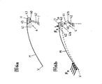
Fig. 6 a is a principle schematic of raising the layout of car bonnet by a rotating lever and the spring that is applied to it;
Fig. 6 b has shown in the layout shown in Fig. 6 a after raising car bonnet;
Fig. 7 is a principle schematic of raising the layout of car bonnet by a lever system;
Fig. 8 a is a principle schematic of raising the layout of car bonnet by a pivotal mounting piston;
Fig. 8 b has shown in the layout shown in Fig. 8 a after raising car bonnet;
Fig. 9 a is a principle schematic of raising the layout in the car bonnet outside by an expandable air bag;
Fig. 9 b has shown in the layout shown in Fig. 9 a after raising car bonnet;
Figure 10 is a principle schematic of raising the layout of car bonnet by an air bag, and wherein this air bag has covered the zone of the self-propelled vehicle adjacent with car bonnet;
Figure 11 is a principle schematic of raising the layout of car bonnet by an air bag, and wherein this air bag extends along the outward flange of car bonnet;
Figure 12 a has shown one the hood hinge that is used in according in the layout of Fig. 1 a to 11;
Figure 12 b has shown the hinge according to Figure 12 a after raising car bonnet.
The specific embodiment
Fig. 1 a has schematically shown the car bonnet M of a self-propelled vehicle, and this car bonnet M that shows among the figure is positioned at the zone of its rear end H, that is, be positioned at its rear end and face the particularly zone of Windshield of crew module.
Be arranged in the travel direction back and in the face of the zone of the rear end H of crew module's car bonnet M, there is an inflector assembly 1 to be disposed between the carrying structure T and car bonnet M of self-propelled vehicle, this inflector assembly can be used to raise car bonnet M in collision case, for human body (pedestrian or the cyclist of back and car bonnet collision are promptly taken place in accident) provides deformation distance.This inflector assembly 1 comprises an air bag 1, and this air bag is disposed on the carrying structure T of self-propelled vehicle, can put on the air by a gas generator 12, and this air bag extends between carrying structure T and car bonnet M under folded state as shown in Figure 1a.Being positioned on car bonnet M above the air bag 10 is a force transmission element 15, and air bag can act on the car bonnet M by this force transmission element 15.
If " pre-crash sensor " by a proximity sensor form detects that directly approach, an inevitable accident, perhaps detect accident by a contact pickup and take place, inflector assembly 1 will be lighted by gas generator 12 and be triggered.Gas generator 12 produces gas and/or discharges the gas of storage in advance by pyrotechnic, and this gas flow in the air bag 10, thereby air bag 10 expands and launches.
After air bag 10 expanded, it pressed to car bonnet M by force transmission element 15, thereby car bonnet M is raised, shown in Fig. 1 b.Under the state of air bag 10 expansions, initial position relatively as shown in Figure 1a, car bonnet M are elevated predetermined distance s in the zone of H in its back-end.This defines in accident the available deformation distance of human body that the back takes place, collide car bonnet M apart from s, thereby impact energy can be disperseed under an in check mode, and can prevent the human body that collided directly with the rigidity vehicle part that is positioned at car bonnet M back, for example engine block contacts.
For this reason, car bonnet M at first will enough stablize, thereby can be raised and unlikely damage by the air bag 10 that expands rapidly in several milliseconds.But car bonnet M also must have enough elasticity, thereby makes that the human body that is collided can be owing to the rigidity of car bonnet M is born serious injury.
After air bag 10 expands, because the gaseous tension in the air bag 10, the latter forms one can stably remain on car bonnet M the locational element that is elevated, and after human body and car bonnet bump, very little extension only takes place, thereby car bonnet M can be moved to the opposite sense of its deflecting direction a.That is to say, in accident with human body---for example upper body---in the relevant initial collision, this initial collision at car bonnet M because the expansion of air bag 10 and after the deflection, this collision can't make the opposite sense motion of car bonnet M to deflecting direction a, thereby impact energy can be disperseed under a kind of controlled way.Therefore, corresponding deformation distance s is still effective to further collision.
In ensuing second time of collision, car bonnet M can have the air extractor vent possibility that becomes by making air bag 10 to the rightabout motion of deflecting direction a.For example, for the air bag of protection automotive occupant, the gas that flow in the air bag 10 by gas generator 12 can be released in the surrounding environment once more.In this way, the pressure in the air bag 10 reduces, thereby in ensuing collision, for example, in the collision of the head of human body and car bonnet M, has a quite low pressure to react on the rightabout motion of car bonnet M to deflecting direction a.Then, car bonnet M can move by the opposite sense to deflecting direction a under the effect of impulsive force, thereby impact energy can be disperseed under a kind of controlled way, and prevents to injure with the human body head of car bonnet M collision.
In this manner; should be noted that; even in the initial collision of human body upper body and car bonnet M, inflector assembly still has second kind of main function, promptly protects direct rigidity vehicle part such as the engine block below being positioned at car bonnet M of human body to contact.
Therefore; layout shown in Fig. 1 a and the 1b can be used to protection and the human body that car bonnet M bumps in the initial collision after air bag 10 expands, by raising car bonnet M the direct rigidity vehicle part below being positioned at car bonnet M of human body is contacted.Then, by the rightabout motion of car bonnet M to deflecting direction a, the impact energy that collision for the second time produces still can be disperseed under a kind of controlled way.
Because in the collision of human body that accident causes and starting motor-driven vehicle hood; generally be that upper body bumps with car bonnet prior to head; therefore the protection of maximum possible is provided for the human body head that is collided, is particularly taking place to prevent reducing of deformation distance s before the head impact.
In an improved form of the layout shown in Fig. 1 a and 1b, the ventilation hole size that is used for air bag 10 exhausts can change in time and be controlled, thereby can obtain a specific time limit in a kind of specific mode, in this time limit can so that impact energy owing to car bonnet M disperses to the rightabout motion of deflecting direction a.In this case, also can control the power that acts in the initial collision on car bonnet M and the inflector assembly 1, make described ventilation hole size change in so a kind of mode, can provide a specific stress level for the collision second time of human body (head), make this collision in a preset time, to finish.
A modification as shown in Figure 1a exemplary embodiments, Fig. 2 a has described a kind of layout that is used to raise car bonnet M, wherein inflector assembly 2 does not comprise an air bag, but comprise a piston 21 that is positioned at cylinder 20, the gas that this piston can be produced by gas generator 22 and raising, then, according to Fig. 2 b, act on the car bonnet M by a force transmission element 25, make car bonnet M to deflecting direction a be elevated one predetermined apart from s.
In this case, inflector assembly 2 acts on the exhaust that pressure on the H zone, car bonnet M rear end can be by piston/ cylinder assembly 20,21 and change.Therefore, in identical mode as Fig. 1 a and the exemplary embodiments shown in the 1b, after car bonnet M is by piston 21 deflections, originally car bonnet M still can be to the opposite sense motion of deflecting direction a, and in after a while moment, after gas discharged from inflector assembly 2, car bonnet M can be to the opposite sense motion of deflecting direction a, and piston 21 is advanced a certain amount of again in cylinder 20.
Fig. 3 a has described an improved procedure of the layout shown in Fig. 2 a, according to this improved procedure, the inflector assembly 2 (comparison diagram 3b) that comprises cylinder 20 and piston 21 is connected to car bonnet M rear end H by a force transmission element and is positioned on the zone of crew module's one side, and described force transmission element is a deformation element 26.This deformation element 26 can be designed to have such elastic deformation, when human body these deformation element 26 bendings when bumping with car bonnet M around the deformation element 26, thereby allow the opposite sense motion of car bonnet M to deflecting direction a, described car bonnet M raises at the piston 21 that has been deflected device 2 before, shown in Fig. 3 b.
When inflector assembly (2) is not reversible design, i.e. piston (21) the power F that can not in head bumps process, cause
hEffect under be pushed and get back in the corresponding cylinder 20, force transmission element (26) is as the design of the deformation element particular importance that seems.
Under the contrast, car bonnet M front end V zone bumps that human body shank for example bumps and the power F that causes
bCan't cause deformation element 26 distortion, thereby can not make the opposite sense motion of car bonnet M to deflecting direction a.Except that other factor, this is the result of the curve design of car bonnet M.
For the exemplary embodiments shown in Fig. 3 a and 3b, can obtain the spatial control (if being fit to) of inflector assembly 2 by this way with controlling to the described time of 2b in conjunction with Fig. 1 a, wherein after car bonnet M is elevated, have only the collision around inflector assembly 2 to occur on the rear end H of car bonnet M, car bonnet just can be to the opposite sense motion of deflecting direction a, and deformation distance also just can reduce.Since in accident pedestrian or cyclist's head often and these zones bump, so this can provide special protection for the head of cooresponding human body.
If in addition, the power/range performance of deformation element 26 can be anisotropic, for example corresponding power F
hVertically acting on the car bonnet M---recurrent during as head impact, the distortion of especially severe can take place in this deformation element 26.
Raise the exemplary embodiments of car bonnet M in being used for shown in Fig. 4 a in the face of the layout of the rear end H of Windshield W, inflector assembly 3 comprises a draw gear 31, this draw gear one end is connected with force transmission element 35 on being positioned at car bonnet M, and the other end is positioned on the take-up device 32.This elastic traction device 31 can be made up of a cable, can be by deflecting element 30 and deflection is once at least between the at both ends.
In collision case, this take-up device 32 is triggered, and to pulling force of draw gear 31 effects, makes draw gear 31 be tightened up by the inflation of pyrotechnic or by electric drive then, and shown in Fig. 4 b, car bonnet M is elevated in the zone of H in its back-end.When car bonnet M is elevated in the zone of H in its back-end, it is around being formed at the pivoted that its front end V, cover lock.Car bonnet M in its back-end the H zone with respect to its initial position (shown in the dotted line among Fig. 4 b) and the distance that is elevated is decided by the position of deflecting element 30.The power that car bonnet M is remained on elevated position is decided by to be acted on pulling force on the draw gear 31 by what take-up device 32 produced.
After accident takes place, when the zone of human body head and car bonnet M rear end H bumps, because impulsive force F
hOpposite with the tension of draw gear, car bonnet M can move to the opposite sense of deflecting direction a, thereby impact energy can be disperseed in a kind of controollable mode.In this case, described movement degree is decided by collision point and the corresponding force F on the zone of car bonnet M rear end H
hDirection.
Under the contrast, by the body part impulsive force F that collision produced that takes place of the zone of shank and car bonnet M front end V for example
bCan't cause the opposite sense motion of car bonnet M to deflecting direction a.In this case, the curvature of car bonnet M also is very important.
If suitable, the pulling force that acts on the draw gear 31 can time to time change, for example, it can be after inflector assembly 3 be triggered in time increase and reduce.
Fig. 5 a has shown an improvement of the exemplary embodiments that is used to raise car bonnet M shown in Fig. 4 a, a tilt flat plate 37 wherein additionally is provided, this tilt flat plate 37 links to each other with car bonnet M by a deformation element 36, and with rotating symmetric element 38 mutual actions, described symmetric element 38 is placed on the load bearing component of self-propelled vehicle in the mode of stationkeeping.The design of tilt flat plate 37, for example, its length and slope define take-up device 32 and trigger the distance that the back raises car bonnet M owing to draw gear 31 tensions, shown in Fig. 5 b.Because this tilt flat plate 37 is connected on the car bonnet M by a deformation element 36, therefore, as described in conjunction with Fig. 4 a and 4b, car bonnet M can not be subjected to any obstruction to the rightabout motion of deflecting direction a under the effect of suitable impulsive force.
Raise in the layout in zone of car bonnet its rear end H in collision case being used for shown in Fig. 6 a, inflector assembly 4 has a lever 41, is fixed on to this lever pivot on the pivot 40, and one end 41b (contrast Fig. 6 b) is connected to a spring element 42.This spring element 42 is designed to an extension spring, and its other end is fixed on the load bearing component T, and to power of pivot lever 41 effects, makes it the tendency around pivot 40 rotations, and the zone of car bonnet rear end H is elevated.But this rotatablely moving stoped by a suspension hook 43, and this suspension hook 43 acts on the pivot lever 41, and stops owing to rotatablely moving that spring element 42 produces.
If human body and car bonnet M bump caused in this case impulsive force F in the zone of front end V after accident takes place
bSuspension hook 43 is opened, thereby discharged pivot lever 41.Pivot lever 41 will rotate with pivot center 40 under the effect of spring element 42 then, in this process, its end 41a away from spring element 42 abuts against force transmission element 45 and acts on, this force transmission element 45 is positioned at the zone of the car bonnet M rear end H of crew module's one side, and car bonnet M is raised.
Even on its end points, shown in Fig. 6 b, after car bonnet M was elevated, pivot lever 41 was still with by impulsive force F
hThe mode of rotating tilts described impulsive force F
hAct on the zone of car bonnet M rear end H, like this, when human body head bumps, this pivot lever just can be to the opposite sense motion of spring element 42 effects, thereby car bonnet M can be reduced at the opposite sense of deflecting direction a.In this case, the rigidity of spring element 42 has determined the required impulsive force size of locomotor cover M.Under the contrast, the leaning angle of pivot lever 41 under the deflection state of inflector assembly 4 determined power F
hDirection, this power F
hCan trigger lever 41 and return rotation.Pivot lever 41 is more little with respect to the inclination of vertical direction, triggers the power F that lever 41 returns rotation
hThe direction scope also just more little.
Generally speaking, important optional parameter comprises the rigidity of spring element 42 in this inflector assembly 4, the length of two throw of levers of pivot lever 41, the quality of car bonnet M and raising the required time of car bonnet M.
In the layout shown in Fig. 6 a and 6b, the initial collision of human body and car bonnet M at first can discharge inflector assembly 4, inflector assembly 4 is raised car bonnet M then, thereby can obtain in ensuing second time collision, the particularly deformation distance in the head impact.
In exemplary embodiments as shown in Figure 7, the inflector assembly 5 that is used for raising in collision case car bonnet M comprises a leverage 51 that has pivot lever 51 and push rod 52,52, wherein pivot lever 51 is pivotally mounted on the fulcrum 50, and push rod 52 is connected on the bumper/spoiler S of vehicle.This push rod 52 is connected on the lower end 51b of pivot lever 51 in the pivotally attached mode.And the upper end 51a of pivot lever 51 is arranged in a Der Laengslenker 57, and this guide rod 57 is fixed on the car bonnet M by a deformation element 55.In this case, deformation element 55 and Der Laengslenker 57 are disposed on the zone of the preceding car bonnet M rear end H of automobile windscreen W.If crash, owing to the collision of human body acts on power F on the bumper/spoiler S
bCan trigger push rod 52 to the rear of longitudinal direction of car direction (opposite) motion, thereby pivot lever 51 is rotated with its turning cylinder 50 with vehicle forward direction.This will raise the zone of car bonnet M rear end H, and the upper end 51a of pivot lever 51 slides in Der Laengslenker 57.Therefore just can obtain in the next second time collision, the particularly deformation distance in the head impact of human body and car bonnet M.Be decided by position of collision and collision direction on the zone of car bonnet M rear end H, deformation element 55, if suitable, and the returning rotation and will make the opposite sense motion of pivot lever 51 from car bonnet M to deflecting direction A.
In this layout as shown in Figure 7, the inflector assembly that is used to raise car bonnet M can not be a leverage, but a draw gear or a tilt flat plate, in this case, the latter should be connected on the bumper/spoiler S.In addition, bumper/spoiler S can be by the speed and push rod 52 mutual actions of a stepping, to increase the miles of relative movement of push rod 52.
Fig. 8 a has shown a layout that is used to raise car bonnet M, the exemplary embodiments of inflector assembly 6 shown in Fig. 3 a wherein is such, formed (contrast Fig. 8 b) by a piston 61 and the cylinder 60 that holds piston, this inflector assembly can be by 62 deflections of a gas generating unit, thus the zone of raising car bonnet M rear end H.Piston 61 equally also is to realize by a force transmission element 65 with being connected of car bonnet M.In contrast to the exemplary embodiments shown in Fig. 3 a, cylinder 60 is installed around the fulcrum D pivotally of carrying automotive component T in the present embodiment.
After inflector assembly 6 is triggered by a suitable sensor, be elevated according to piston 61 and the car bonnet M of Fig. 8 b, the cylinder 60 moving axis D that rotates simultaneously rotates slightly.Compressive force F in the cylinder 60
fM remains on the inflection point with car bonnet.In case the collision of the collision, particularly head of human body and car bonnet M back-end region takes place, if the power F that collision produces
hPower F with gas generation in the cylinder 60
fOn the contrary, described car bonnet M will move to the opposite sense of deflecting direction a, thereby impact energy can be disperseed under a kind of controlled way.
Under the contrast, if because the impulsive force F that the human body collision is produced
bAct on the zone of car bonnet M front end V, because described impulsive force F
bDo not have an enough big component and offset the power F that applies by piston 61
f, so car bonnet M can be to the opposite sense motion of deflecting direction a.
In addition, can make corresponding modification to piston 61 (such as on the position of piston rod), make it and a clamping element mutual action, this clamping element stops the opposite sense motion of piston 61 to deflecting direction a, in design-calculated was arranged by this way, the gripping power in common human body upper body partly collides was more a lot of greatly than the gripping power in the human body head collision, therefore in this manner, only when head impact took place, piston 61 just can be to the opposite sense motion of deflecting direction a.
Fig. 9 a has shown a modification of exemplary embodiments as shown in Figure 1a, and its inflector assembly 1 with an expandable air bag 10 is disposed between the external panelling (outside Ma) of a supporting construction Mt and car bonnet.That is to say that in this case, car bonnet M is a designing two portions, has metastable supporting construction Mt, and the outside Ma of definite car bonnet M configuration design.According to Fig. 9 a, air bag 10 is disposed between these parts of car bonnet M with folding state, and the supporting construction Mt of car bonnet M has a corresponding pit R, is used to hold air bag 10 and gas generator 12, described gas generator 12 protrudes in the air bag 10, is used to heave air bag.Air bag 10 and gas generator 12 are fixed on the supporting construction Mt of car bonnet M by suitable retaining element 13 (for example screw or rivet) in combination.
If sensor to an imminent accident or detect an accident that has taken place, air bag 10 is just by gas generator 12 bulging, and therefore, from Fig. 9 b as can be seen, the outside Ma of car bonnet M is lifted away from supporting construction Mt.In this way, can obtain the required deformation distance of outside Ma collision of pedestrian or cyclist and car bonnet M.Air bag 10 can be to be controlled in conjunction with Fig. 1 a and the described mode of Fig. 1 b.That is to say that after the outside of car bonnet M Ma was elevated, by the gas in the air bag 10 is carried out certain release, the power on the outside Ma that stress level in the air bag 10 and air bag 10 act on car bonnet M will time to time change.This particularly occurs in about in the accident of being involved in and be positioned at the moment that the head of the human body outside the self-propelled vehicle may bump and the setting pressure level makes this stress level can allow the opposite sense motion of the outside Ma of car bonnet M to deflecting direction a.
Than the whole car bonnet that comprises supporting construction Mt and outside Ma, because the outside Ma of car bonnet M has lower rigidity, so air bag 10 must have big relatively volume, to support the outside Ma of car bonnet M in bigger zone.This also allows air bag 10 to be divided into a plurality of chambers, and the chamber that wherein is assigned to upper body collision is inflated earlier and charges into higher relatively air pressure, and is inflated and charges into relatively low air pressure after being assigned to the chamber of head impact (being positioned at the back-end region of car bonnet M).This can guarantee by following mode: set some overfolw holes, make gas flow into the chamber of distributing to head by these overfolw holes from the chamber of distributing to upper body.In addition, for different collision areas, also can provide a plurality of air bags that have different air pressure inside and fill by the time biasing.
In exemplary embodiments as shown in figure 10, air bag 10 act as inflector assembly 1, is used to raise the outside Ma of car bonnet M, to protect the human body that is positioned at outside the self-propelled vehicle in accident.In this case, air bag one end of expansion is supported on the supporting construction Mt, and the other end acts on the outside Ma of car bonnet M simultaneously, makes it to deflect.
Simultaneously, air bag 10 is under swelling state, H zone and the vertically this design of the outside Ma air bag 10 of side S zone support car bonnet M in its back-end, for the collision human body provides an impingement area especially uniformly, thereby on whole car bonnet M, provide the prevention face of a relative softness equably for head, upper body and other parts of collision human body.
This layout according to Figure 10 can also be used for following situation in an identical manner, is not only the outside Ma of car bonnet M, also has the individual whole car bonnet M that is raised by the inflector assembly 1 that with air bag 10 is form.
In exemplary embodiments as shown in figure 11, car bonnet M integrally is deflected device 1 and raises when having an accident, described inflector assembly is the air bag 10 ' of a U-shaped, the base portion 100 ' of this air bag stretches along the rear end H of car bonnet M, its two branches 101 ', 102 ' separates from base portion 100 ' at angle, and side S stretching, extension longitudinally below car bonnet M.Thereby car bonnet M is supported under the state of raising on three sides by air bag 10 '.
Under the situation of this layout, under the state that car bonnet M raises, the whole surface of car bonnet M is stressed evenly, thereby at car bonnet M during to the motion of the opposite sense of deflecting direction a, no matter the human body collision on which position of car bonnet M, can both provide soft as much as possible impingement area for the collision human body.
Be used for raising car bonnet is positioned at the human body outside the self-propelled vehicle with protection exemplary embodiments in conjunction with Fig. 1 a to 11 is described; car bonnet M is that rotating shaft is rotated with its front end V (lock set for example) under every kind of situation; and in this process, particularly the zone of the rear end H of car bonnet is elevated.On the other hand, in order can for example to change oil under the situation of repairing or other reasons and hood up, car bonnet also should be that rotating shaft is rotated with its rear end.That is to say; on the one hand; car bonnet M must fix with the vehicle body pivot on the zone of H in its back-end; when repairing, can raise car bonnet; and another fermentation; the H zone, rear end of car bonnet M also must be able to be elevated, with enable to realize according to of the present invention in accident this defencive function of the human body outside the protection self-propelled vehicle.
A hinge that can satisfy these conditions is shown in Figure 12 a.This hinge 9 has the base portion 90 and the top 95 that are fixed on the vehicle body, and this top 95 can be rotated with respect to base portion 90, and can be connected on the car bonnet M.Lever 91 is adjusted by two in top 95,92 and be connected with base portion 90, adjust lever 91 for described two, 92 in its bottom zone by hinge- point 91a, 92a and be hinged to one with base portion 90 bonded assembly holding elements 900 on, in addition at its apex zone by other hinge- point 91b, 92b and being hinged on the top 95 of hood hinge 9.This makes top 95 to rotate with respect to base portion 90 by adjusting lever 91,92, and car bonnet is the axle rotation with its rear end, thereby the front end of car bonnet is upwards raised, and those zones that covered by car bonnet M in the vehicle can be approaching.
With the holding elements 900 of two bottom pivotal joints of adjusting levers 91,92 by two retaining elements (for example rivet) 90a, 90b and being connected on the base portion 90.Retaining element 90a on the elongated holding element 900,90b is positioned on the two ends of the vertical side of holding element.Be disposed in the situation in the back-end region of car bonnet of self-propelled vehicle for hood hinge 9, preceding retaining element 90b in working direction designs in a kind of special mode, or has a zone of reduction, make the connection between base portion 90 and the holding element 900 to open, to raise the rear end of car bonnet.This is because when preceding retaining element 90b discharged, back retaining element 90a act as a junction, made holding element 900 serve as spool and with respect to base portion 90 rotations, shown in Figure 12 b with this junction, back 90a.Then, holding element 900 and two adjust levers 91,92 and form a leverage together, and this leverage allows the rear end of car bonnet vertically to raise, shown in the layout shown in Fig. 1 a to 11 like that.
Be connected with a kind of car bonnet shown in the 12b or the design of hood hinge 9 is according to a such principle as Figure 12 a, described hood hinge can change by the effect of a specific power, thereby the rear end (being connected on the vehicle body by hood hinge) of car bonnet can be elevated.According to another kind of form, such power can itself (with reference to Fig. 1 a to 11) be applied by the inflector assembly 1 that is used for deflection car bonnet M.According to another embodiment, an independent device can be provided, this device applies effect to a specific part of hood hinge 9, with the change hood hinge, thereby the rear end of car bonnet is elevated.
Certainly, also can hood hinge be separated fully from the rear end part of vehicle body by destroying hood hinge 9.For this reason, for example, adjust lever 91,92 and can from base portion 90 or top 95, separate.The exemplary embodiments of the hood hinge shown in Figure 12 a and 12b, only need make amendment and need not destroy and just can be used for raising the car bonnet rear end, has such advantage, can make hood hinge 9 be used for raising of limiting engine cover M simultaneously by inflector assembly (with the form of interception band), thereby avoid too much raising.This is because can make the human body of collision collide the lagging dege of car bonnet once more like this, thereby increases the risk that is hurt.
Claims (43)
1. one kind is used for deflection self-propelled vehicle external panelling parts---are made of---car bonnet particularly or boot-lid panel wing plate layout, when having an accident, people outside being positioned at self-propelled vehicle be deflected parts collisions, can disperse impact energy to the opposite sense motion of deflecting direction by making described parts, this layout has a device that is used for the deflection external panelling, this device acts at least one point of described parts, when the people collides on these parts, allow of the opposite sense motion of these parts, inflector assembly (1 to deflecting direction, 2,3,4,5,6) point of action is in the zone of parts (M) in the face of crew module's rear end (H)
It is characterized in that described inflector assembly (1,2,3,4,5,6) has an element (10; 10 '; 20,21; 26; 31; 43; 55; 60,61), the people be deflected parts (M) when bumping, impulsive force (F wherein
b, F
h) act on the opposite sense of deflecting direction, this element can stop the opposite sense motion of external panelling parts (M) to deflecting direction (a); And inflector assembly (1,2,3,4,5,6) as the function of collision time, position of collision and/or collision direction Be Controlled by this way, as the impact moment of external panelling deflection component (M) and/or the function of position of collision and/or collision direction, this inflector assembly (1,2,3,4,5,6) allow the opposite sense motion of external panelling parts (M), perhaps stop this motion to take place to prevent it to deflecting direction (a).
2. layout as claimed in claim 1 only is characterized in that after the fixed time after external panelling parts (M) deflection, and inflector assembly (1,2,3,4,5,6) just allows the opposite sense motion of these parts (M) to deflecting direction (a).
3. layout as claimed in claim 1 or 2 is characterized in that inflector assembly (1,2,6) is at the fluid pressure effect deflect external panelling parts (M) of gas particularly.
4. layout as claimed in claim 3, the pressure that it is characterized in that described fluid are the control that is subjected to the time, reduce after parts (M) deflection of external panelling.
5. layout as claimed in claim 4 is characterized in that the described pressure that is deflected the fluid on the parts (M) that acts on external panelling can reduce by discharging some fluids.
6. layout as claimed in claim 5 is characterized in that providing air extractor vent to discharge fluid.
7. layout as claimed in claim 6 is characterized in that the discharge area of air extractor vent can be controlled.
8. layout as claimed in claim 1 is characterized in that inflector assembly (1,2,3,6) can be triggered pyrotechnics.
9. layout as claimed in claim 3 is characterized in that described pressure is that pyrotechnic ground produces.
10. layout as claimed in claim 1 is characterized in that inflector assembly (1,2) comprises an element (10,21) that can be filled fluid, and this element acts on the parts (M) of external panelling when charging into fluid.
11. layout as claimed in claim 1 is characterized in that inflector assembly (2,6) comprises a piston (21,61) that can act on the external panelling parts (M).
12. layout as claimed in claim 3 is characterized in that described fluid is used for filling into the element (10) that can fill, or is used for mobile piston (21,61).
13. layout as claimed in claim 1, it is characterized in that inflector assembly can be like this by locking, thereby do not allow the rightabout any motion of external panelling parts (M) to deflecting direction (a), and this locking can be released by human body and external panelling parts (M) collision, thereby in further colliding, described parts are to the opposite sense motion of deflecting direction (a).
14. layout as claimed in claim 13 is characterized in that providing a suspension hook that is used for locking.
15. layout as claimed in claim 1 only is characterized in that inflector assembly (2,3,4,5,6) just can be to the opposite sense motion of deflecting direction (a) when human body collides on the specific region of external panelling parts (M).
16. layout as claimed in claim 15 is characterized in that described zone has surrounded inflector assembly (2,3,4,5,6) and acted on point on the parts (M).
17. layout as claimed in claim 1, but it is characterized in that inflector assembly passes through elasticity or plastic deformation element (10; 20,21; 26; 42; 55) act on the external panelling parts (M).
18., but it is characterized in that colliding elasticity or plastic deformation element (10 as the people as the described layout in one of claim 16 and 17; 20,21; 26; 31; 42; When 55) external panelling parts (M) are on every side gone up, this element (10; 20,21; 26; 31; 42; 55) move, make the opposite sense motion of external panelling parts (M) to deflecting direction (a).
19. layout as claimed in claim 17 is characterized in that described deformation element is formed by a spring element (26,42,55).
20. layout as claimed in claim 17 is characterized in that described deformation element is formed by an elastic coupling element (31) that is positioned between inflector assembly (3) and the external panelling parts (M).
21. layout as claimed in claim 17 is characterized in that described deformation element is formed by a telescopic element (20,21).
22. layout as claimed in claim 1 is characterized in that inflector assembly (1,2,3,4,5,6) be a kind of to the reversible design of small part, thereby by inflector assembly (1,2,3,4,5,6) element moves round about in the deflection of parts (M) and may make the opposite sense motion of external panelling parts (M) to deflecting direction (a).
23. layout as claimed in claim 1 is characterized in that having only when human body collides on the external panelling parts (M) in the specific direction scope, inflector assembly (2,3,4,5,6) just can be to the opposite sense motion of deflecting direction (a).
24. layout as claimed in claim 17 is characterized in that deformation element (20,21; 26; 60,61) only just can be out of shape during the collision in the specific direction scope.
25. layout as claimed in claim 23, it is characterized in that inflector assembly (2,4,5) at least one element (21,41,51)---described element can move for deflection external panelling parts (M), be to design like this and/or arrange, inflector assembly (2,4,5) just allows the opposite sense motion of parts (M) to deflecting direction (a) when wherein only bumping in the specific direction scope.
26. layout as claimed in claim 1 is characterized in that inflector assembly (4,5) has a leverage, is used for deflection external panelling parts (M).
27. layout as claimed in claim 1 is characterized in that inflector assembly (3) has a movable draw gear that is directed to (31), is used for deflection external panelling parts (M).
28. layout as claimed in claim 26 is characterized in that described leverage has at least one lever (41,51), this lever can rotate and be used for deflection external panelling parts (M).
29. layout as claimed in claim 27 is characterized in that described draw gear (31) can be tightened up, and is used for deflection external panelling parts (M).
30., it is characterized in that in order to make the opposite sense motion of external panelling parts (M) to deflecting direction (a), lever (41,51) is rotated as claim 28 or 29 described layouts, perhaps draw gear (31) is subjected to the load on the opposite sense of its tension.
31. layout as claimed in claim 23 is characterized in that only just may causing the reversing sense motion to the tension direction of draw gear (31) of the rotation of lever (41,51) or external panelling part (M) when specific direction scope inner impact external panelling parts (M).
32. layout as claimed in claim 11 is characterized in that only triggering the opposite sense motion of piston (21,61) to deflecting direction (a) at specific direction scope inner impact external panelling parts (M) Shi Caihui.
33. layout as claimed in claim 1 is characterized in that inflector assembly (4) is connected with an elastic element (42), this element is gone up inflector assembly (4) pretension at deflecting direction (a).
34. layout as claimed in claim 33 is characterized in that providing a locking element (43), this locking element (43) prevents inflector assembly (4) deflection external panelling parts (M).
35. layout as claimed in claim 34 is characterized in that described locking can be collided on the vehicle by the people and cancels.
36. layout as claimed in claim 1 is characterized in that inflector assembly (4,5) can be activated by the initial collision of people and vehicle, thereby makes external panelling parts (M) deflection.
37. layout as claimed in claim 36 is characterized in that the masterpiece that produces is used on the inflector assembly (5) in collision, thereby activates inflector assembly (5).
38. layout as claimed in claim 1 is characterized in that the function that inflector assembly (1,2,3,6) can be used as the signal that is connected to the sensor on the inflector assembly activates.
39. layout as claimed in claim 1 is characterized in that external panelling parts (M) are made up of a wing plate of self-propelled vehicle.
40. layout as claimed in claim 39 is characterized in that described wing plate (M) is a car bonnet or boot-lid panel.
41. layout as claimed in claim 40, the point of action that it is characterized in that inflector assembly (1,2,3,4,5,6) is in the zone of wing plate (5) in the face of crew module's rear end (H).
42. layout as claimed in claim 20 is characterized in that described elastic coupling element is the elastic traction device.
43. layout as claimed in claim 35 is characterized in that described locking can be collided external panelling parts (M) by the people and go up and cancel.
Applications Claiming Priority (4)
| Application Number | Priority Date | Filing Date | Title |
|---|---|---|---|
| DE10231796 | 2002-07-10 | ||
| DE10231796.8 | 2002-07-10 | ||
| DE10234897.9 | 2002-07-26 | ||
| DE10234897A DE10234897A1 (en) | 2002-07-10 | 2002-07-26 | Arrangement for deflecting a part of the outer skin of a motor vehicle |
Publications (2)
| Publication Number | Publication Date |
|---|---|
| CN1668495A CN1668495A (en) | 2005-09-14 |
| CN100400346C true CN100400346C (en) | 2008-07-09 |
Family
ID=30116635
Family Applications (1)
| Application Number | Title | Priority Date | Filing Date |
|---|---|---|---|
| CNB03816373XA Expired - Fee Related CN100400346C (en) | 2002-07-10 | 2003-06-25 | System for deviating part of the external panelling of a motor vehicle |
Country Status (6)
| Country | Link |
|---|---|
| US (1) | US7614472B2 (en) |
| EP (1) | EP1519857B1 (en) |
| JP (1) | JP4113534B2 (en) |
| CN (1) | CN100400346C (en) |
| DE (1) | DE50304872D1 (en) |
| WO (1) | WO2004007247A2 (en) |
Families Citing this family (18)
| Publication number | Priority date | Publication date | Assignee | Title |
|---|---|---|---|---|
| GB2373218B (en) * | 2001-03-13 | 2004-12-15 | Autoliv Dev | Improvements in or relating to a safety arrangement |
| US7159685B2 (en) * | 2001-03-13 | 2007-01-09 | Autoliv Development Ab | Safety arrangement for a vehicle |
| DE10341368A1 (en) * | 2003-09-03 | 2005-04-07 | Takata-Petri Ag | Safety device on a motor vehicle for the protection of pedestrians and cyclists |
| DE10346213A1 (en) * | 2003-10-06 | 2005-04-21 | Bosch Gmbh Robert | Regulating load condition of energy storage device for vehicle with hybrid drive involves regulating state of charge of energy storage device depending on vehicle's speed of travel |
| GB2410782B (en) * | 2004-02-09 | 2007-07-11 | Autoliv Dev | Improvements in or relating to a safety device |
| US7063377B2 (en) * | 2004-08-06 | 2006-06-20 | General Motors Corporation | Hood lift mechanisms utilizing active materials and methods of use |
| EP1736380B1 (en) * | 2005-06-23 | 2008-07-09 | Mazda Motor Corporation | A safety device of a vehicle and a vehicle provided therewith |
| US7631928B2 (en) * | 2007-11-09 | 2009-12-15 | Toyota Motor Engineering & Manufacturing North America, Inc. | Vehicle hood reinforcement structures |
| DE102009042062A1 (en) * | 2009-09-17 | 2011-03-24 | GM Global Technology Operations, Inc., Detroit | Body for motor vehicle, has carrier structure and engine hood that is linked at carrier structure, where engine hood is supported at carrier structure by support |
| DE102011118123A1 (en) * | 2011-11-10 | 2013-05-16 | GM Global Technology Operations LLC (n. d. Gesetzen des Staates Delaware) | Motor vehicle body with active hood |
| DE102013213793A1 (en) | 2013-07-15 | 2015-01-15 | Volkswagen Aktiengesellschaft | Pedestrian protection device for a vehicle |
| CN104192091B (en) * | 2014-09-16 | 2016-10-26 | 江苏天诚车饰科技有限公司 | A kind of hood lifting apparatus |
| DE202014008603U1 (en) * | 2014-10-29 | 2016-02-01 | GM Global Technology Operations LLC (n. d. Ges. d. Staates Delaware) | Airbag module assembly for a vehicle and vehicle with the airbag module assembly |
| JP6260518B2 (en) * | 2014-11-21 | 2018-01-17 | トヨタ自動車株式会社 | Pop-up hood device for vehicle |
| DE102015001180A1 (en) * | 2015-01-30 | 2016-08-04 | Hella Kgaa Hueck & Co. | Actuator for a moving part |
| US9725060B1 (en) * | 2015-09-03 | 2017-08-08 | Waymo Llc | Reducing surface rigidity of a vehicle |
| DE102017008818A1 (en) | 2017-09-20 | 2019-03-21 | Daimler Ag | Airbag arrangement for a motor vehicle |
| CN117141219B (en) * | 2023-10-24 | 2024-01-26 | 康硕(德阳)智能制造有限公司 | Shock-absorbing automobile engine support |
Citations (5)
| Publication number | Priority date | Publication date | Assignee | Title |
|---|---|---|---|---|
| WO2000069708A1 (en) * | 1999-05-17 | 2000-11-23 | Edscha Ag | Front hood assembly |
| WO2000069703A1 (en) * | 1999-05-17 | 2000-11-23 | Edscha Ag | Front hood assembly |
| CN1352606A (en) * | 1999-05-17 | 2002-06-05 | 埃德沙股份公司 | Front hood system of engine |
| CN1352604A (en) * | 1999-05-17 | 2002-06-05 | 埃德沙股份公司 | Front hood assembly of engine |
| CN1352605A (en) * | 1999-05-17 | 2002-06-05 | 埃德沙股份公司 | Front hood assembly of engine |
Family Cites Families (27)
| Publication number | Priority date | Publication date | Assignee | Title |
|---|---|---|---|---|
| JPS58211975A (en) * | 1982-06-03 | 1983-12-09 | Nissan Motor Co Ltd | Supporting structure of car hood |
| GB9312721D0 (en) * | 1993-06-19 | 1993-08-04 | Jaguar Cars | Vehicle bonnets |
| DE19512600B4 (en) | 1995-04-04 | 2007-07-26 | Albrecht Dr.-Ing. Hartmann | Vehicle, in particular compact vehicle |
| DE29720461U1 (en) | 1997-11-19 | 1998-02-26 | Trw Automotive Safety Sys Gmbh | Airbag with adjustable outlet cross-section |
| JPH11310157A (en) | 1998-04-27 | 1999-11-09 | Honda Motor Co Ltd | Impact absorbing device for vehicle hood |
| JP3687418B2 (en) | 1998-06-26 | 2005-08-24 | 日産自動車株式会社 | Bounce hood |
| JP3675209B2 (en) | 1999-01-14 | 2005-07-27 | 日産自動車株式会社 | Vehicle hood device |
| JP3317441B2 (en) * | 1999-07-19 | 2002-08-26 | 本田技研工業株式会社 | Vehicle hood device |
| US6293362B1 (en) * | 1999-07-09 | 2001-09-25 | Honda Giken Kogyo Kabushiki Kaisha | Vehicle hood apparatus |
| DE19946408A1 (en) * | 1999-09-28 | 2001-05-03 | Siemens Restraint System Gmbh | System for raising and lowering a hood of a motor vehicle |
| JP4423738B2 (en) | 2000-03-31 | 2010-03-03 | タカタ株式会社 | Airbag |
| DE10020658B4 (en) | 2000-04-27 | 2014-05-22 | Volkswagen Ag | Vehicle, in particular motor vehicle, with a crash-active vehicle front structure |
| DE10021143A1 (en) | 2000-04-29 | 2001-10-31 | Volkswagen Ag | Safety device for vehicle has energy storage unit with energy storage devices activated independently and/or at time intervals depending on collision conditions to raise hood |
| JP3857025B2 (en) | 2000-07-19 | 2006-12-13 | 本田技研工業株式会社 | Vehicle hood device |
| US6554093B2 (en) * | 2000-07-19 | 2003-04-29 | Honda Giken Kogyo Kabushiki Kaisha | Vehicular hood device |
| US6520276B2 (en) * | 2000-07-19 | 2003-02-18 | Honda Giken Kogyo Kabushiki Kaisha | Vehicle hood apparatus |
| US6513617B2 (en) * | 2000-07-26 | 2003-02-04 | Honda Giken Kogyo Kabushiki Kaisha | Vehicle hood apparatus |
| JP3795313B2 (en) * | 2000-09-19 | 2006-07-12 | 本田技研工業株式会社 | Vehicle hood device |
| JP3857029B2 (en) * | 2000-09-19 | 2006-12-13 | 本田技研工業株式会社 | Vehicle sensor system |
| DE10102760B4 (en) | 2001-01-23 | 2019-07-18 | Volkswagen Ag | Safety systems with an impact-absorbing front hood on a vehicle |
| GB2372536B (en) | 2001-02-15 | 2003-09-10 | Ford Global Tech Inc | A hinge assembly and a motor vehicle including same |
| DE10108882A1 (en) | 2001-02-23 | 2002-09-05 | Volkswagen Ag | Lifting device for e.g. engine bonnet to protect pedestrians during accidents has power limitation device with shear bolt integrated in bonnet locking device |
| JP2003095044A (en) * | 2001-09-06 | 2003-04-03 | Takata Corp | External surface expanding air bag device |
| JP3791379B2 (en) * | 2001-10-02 | 2006-06-28 | トヨタ自動車株式会社 | Hood airbag device |
| US6415883B1 (en) * | 2002-01-24 | 2002-07-09 | Ford Global Technologies, Inc. | Deployable A-pillar covers for pedestrian protection |
| JP3682502B2 (en) * | 2002-04-12 | 2005-08-10 | 本田技研工業株式会社 | Outside air bag apparatus |
| EP1400416B8 (en) * | 2002-09-20 | 2008-07-09 | Ford Global Technologies, LLC | Pedestrian safety device |
-
2003
- 2003-06-25 JP JP2004520299A patent/JP4113534B2/en not_active Expired - Fee Related
- 2003-06-25 US US10/520,627 patent/US7614472B2/en not_active Expired - Fee Related
- 2003-06-25 CN CNB03816373XA patent/CN100400346C/en not_active Expired - Fee Related
- 2003-06-25 DE DE50304872T patent/DE50304872D1/en not_active Expired - Lifetime
- 2003-06-25 WO PCT/DE2003/002153 patent/WO2004007247A2/en active IP Right Grant
- 2003-06-25 EP EP03763582A patent/EP1519857B1/en not_active Expired - Fee Related
Patent Citations (5)
| Publication number | Priority date | Publication date | Assignee | Title |
|---|---|---|---|---|
| WO2000069708A1 (en) * | 1999-05-17 | 2000-11-23 | Edscha Ag | Front hood assembly |
| WO2000069703A1 (en) * | 1999-05-17 | 2000-11-23 | Edscha Ag | Front hood assembly |
| CN1352606A (en) * | 1999-05-17 | 2002-06-05 | 埃德沙股份公司 | Front hood system of engine |
| CN1352604A (en) * | 1999-05-17 | 2002-06-05 | 埃德沙股份公司 | Front hood assembly of engine |
| CN1352605A (en) * | 1999-05-17 | 2002-06-05 | 埃德沙股份公司 | Front hood assembly of engine |
Also Published As
| Publication number | Publication date |
|---|---|
| JP2005532226A (en) | 2005-10-27 |
| US20060060408A1 (en) | 2006-03-23 |
| JP4113534B2 (en) | 2008-07-09 |
| WO2004007247A3 (en) | 2004-09-23 |
| EP1519857B1 (en) | 2006-08-30 |
| DE50304872D1 (en) | 2006-10-12 |
| WO2004007247A2 (en) | 2004-01-22 |
| EP1519857A2 (en) | 2005-04-06 |
| CN1668495A (en) | 2005-09-14 |
| US7614472B2 (en) | 2009-11-10 |
Similar Documents
| Publication | Publication Date | Title |
|---|---|---|
| CN100400346C (en) | System for deviating part of the external panelling of a motor vehicle | |
| KR100770135B1 (en) | Road walker protecting apparatus of hood in vehicle | |
| KR101096169B1 (en) | Pedestrian protection automotive hood hinge assembly | |
| EP1604874B1 (en) | Controller for collision object protection device | |
| JP5154229B2 (en) | Safety device | |
| EP1400416B1 (en) | Pedestrian safety device | |
| JP4088624B2 (en) | Device to protect people outside the car | |
| US7410027B2 (en) | Device for reducing the impact for pedestrians | |
| EP2036786B1 (en) | Hood pop-up system and hood pop-up method for a vehicle | |
| CZ20014025A3 (en) | Arrangement of front bonnet | |
| US20050279550A1 (en) | Hinge arrangement | |
| MXPA01011779A (en) | Front hood system. | |
| CN1196705A (en) | Side air bag incorporated in vehicle outer armrest | |
| EP2812215A1 (en) | Active hood or bonnet system for a vehicle | |
| MXPA01011780A (en) | Front hood assembly. | |
| MXPA01011781A (en) | Front opening hood system. | |
| MXPA01011750A (en) | Front hood assembly. | |
| US7380625B2 (en) | Vehicle engine compartment hood | |
| EP1615808B1 (en) | A safety device | |
| GB2368562A (en) | An air-bag arrangement for deployment between the rear of the bonnet and the windscreen of an automobile | |
| KR100613778B1 (en) | Air bag damping typed hood lift device in vehicle | |
| KR20080017726A (en) | Active hood system of automobile | |
| GB2499032A (en) | Active hood or bonnet system for a vehicle | |
| RU204399U1 (en) | Active bonnet for pedestrian protection | |
| WO2014197367A1 (en) | Hinge mechanism for connecting a bonnet to a motor vehicle |
Legal Events
| Date | Code | Title | Description |
|---|---|---|---|
| C06 | Publication | ||
| PB01 | Publication | ||
| C10 | Entry into substantive examination | ||
| SE01 | Entry into force of request for substantive examination | ||
| C14 | Grant of patent or utility model | ||
| GR01 | Patent grant | ||
| C17 | Cessation of patent right | ||
| CF01 | Termination of patent right due to non-payment of annual fee |
Granted publication date: 20080709 Termination date: 20130625 |