CN100398429C - Hoisting and stabilization system for suspended load support - Google Patents
Hoisting and stabilization system for suspended load support Download PDFInfo
- Publication number
- CN100398429C CN100398429C CNB2004100766638A CN200410076663A CN100398429C CN 100398429 C CN100398429 C CN 100398429C CN B2004100766638 A CNB2004100766638 A CN B2004100766638A CN 200410076663 A CN200410076663 A CN 200410076663A CN 100398429 C CN100398429 C CN 100398429C
- Authority
- CN
- China
- Prior art keywords
- hanging element
- load support
- pulley
- cable
- steering support
- Prior art date
- Legal status (The legal status is an assumption and is not a legal conclusion. Google has not performed a legal analysis and makes no representation as to the accuracy of the status listed.)
- Expired - Fee Related
Links
Images


Classifications
-
- B—PERFORMING OPERATIONS; TRANSPORTING
- B66—HOISTING; LIFTING; HAULING
- B66C—CRANES; LOAD-ENGAGING ELEMENTS OR DEVICES FOR CRANES, CAPSTANS, WINCHES, OR TACKLES
- B66C13/00—Other constructional features or details
- B66C13/04—Auxiliary devices for controlling movements of suspended loads, or preventing cable slack
- B66C13/06—Auxiliary devices for controlling movements of suspended loads, or preventing cable slack for minimising or preventing longitudinal or transverse swinging of loads
-
- B—PERFORMING OPERATIONS; TRANSPORTING
- B66—HOISTING; LIFTING; HAULING
- B66C—CRANES; LOAD-ENGAGING ELEMENTS OR DEVICES FOR CRANES, CAPSTANS, WINCHES, OR TACKLES
- B66C13/00—Other constructional features or details
- B66C13/04—Auxiliary devices for controlling movements of suspended loads, or preventing cable slack
- B66C13/08—Auxiliary devices for controlling movements of suspended loads, or preventing cable slack for depositing loads in desired attitudes or positions
Abstract
The suspension and hoisting system for a load support comprises two cable circuits, each comprising a cable fixed at one of the ends thereof to a fixed point and at the other end to a lifting apparatus and being reeved around deflection pulleys mounted on two parallel shafts located adjacent one and the other end, respectively, of the load support, the lifting apparatus of one of the two cable circuits being provided above one of the ends of the load support and the lifting apparatus of the other cable circuit being provided above the other end of the load support. The cable of at least one of the cable circuits is reeved successively around at least two coaxial deflection pulleys mounted on each end shaft according to such a path that on at least one of the end shafts at least one pulley of said one cable circuit rotates in the same direction as at least one pulley of the other cable circuit under identical lifting or lowering action of the two lifting apparatus, while these two pulleys are constrained to rotate in opposite directions by the same downwardly oriented force independently of the action of the lifting apparatus. According to the invention these two pulleys are interlocked to reduce or eliminate any tendency of the load support to incline under the effect of this downward force.
Description
Technical field
The present invention relates to a kind of system that is used to hang and promote load support.
Background technology
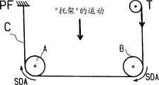
What a kind of known type was arranged is used to hang and promote device such as work gondola equivalent-load carriage, wherein this load support is hung by hanging section by at least two four of constituting such as hanging elements such as cable or ropes only altogether, each cable or rope extend downwards from the attachment point that is positioned at top, one of load support opposite end, and walk around such as circular rotatable steering support members such as pulleys, the two ends of contiguous this load support of steering support member are provided with, and each be connected to be positioned at this load support other end top such as bonts such as capstan winches.The hanging element integral body that these circular support part settings are used for being associated with it is rotated.This circular support part needn't be arranged on the end of this load support, only needs the center equidistant apart towards its opposite end and this load support, and can not change required effect.Usually, the suspension section of recommending this device hangs section along vertical setting but this suspension gear also can have bevelled.In addition, the center of gravity (G) that should be understood that this load support should be positioned at the below of the traversing section of the cable of engages pulley or rope, is stable so that guarantee carriage at horizontal direction.This known system has following advantage, promptly only needs two bonts or winch to be used for four and hangs section.Fig. 1 shows the scheme drawing of this known devices.
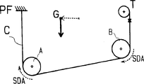
Aforesaid device has following disadvantage, promptly this device provide a kind of when load when wherein an end moves from carriage mass axis Ag towards load support, since pulley roll and towards the load support of load-side fore-and-aft tilt at cable or rope.For example, one moves from its center towards gondola one side or opposite side when standing in the user who constitutes, is positioned at first on the load support of level attitude by gondola, and this gondola will present the position towards identical lopsidedness.This inclination continues to increase, until this gondola bottom near be positioned at load on the opposite side of its side that moves cable or the suspension section positions aligning of rope, as shown in Figure 2.In fact, be under the situation of gondola at load support, this guiding that moves through the suspension section by means of the gondola vertical stretch, such as stirrup, is restricted, but can not disappears.This aforesaid restrained motion is shown among Fig. 3.
Hereinafter be particularly related to the load support that constitutes by gondola, one after the other be described with two hanging elements then with one, each hanging element is made of cable or the rope of walking around pulley and driven by convoluted capstan winch or winch, but the present invention also can be applied to any bont that other is equal to and any load support that other is equal to, for example wherein hanging element can be that chain, circular cable or rope steering support member will be that sprocket wheel and/or load support will be those of jacking floor beam, but the present invention is not limited to these embodiment.In addition, following explanation is applied to such as described system, and wherein by realize replenishing backhaul between the carriage two ends, at least one in two hanging elements can be walked around on each end axle two with top sheave.It also is applicable to an embodiment, and wherein system has two above hanging elements.Following explanation is applied to have the vertical embodiment that hangs section especially, if but specific reasons needs a kind of like this configuration, and the present invention also is applied to have the embodiment of superconducting tilting suspension section.Unique requirement of the suspension that forms specific to pulley and cable, rope or belt is, consider the weight of carriage and its load, friction coefficient between pulley and cable, rope or the belt should be, cooperation between pulley and cable, rope or belt is achieved basically, and cable does not take place, rope or the slippage of belt in pulley groove.
Summary of the invention
The objective of the invention is to utilize simple mechanism that a kind of system with described type of following advantage is provided, when the point of action of load not or when no longer being positioned at the load support center, that is to say apart from each hitch point of system not to be in when equidistant, keep load support to be in stable and unaltered position.
For achieving the above object, according to the present invention, a kind of suspension and elevator system that is used for load support is provided, be applied to two opposed ends of described load support, described load support is hung by four suspension sections that are made of at least two hanging elements at least, each hanging element is hung towards another carriage end towards one of described carriage end and from the drive element of bont from an attachment point by walking around circular hanging element steering support member, described circular hanging element steering support member rotates with hanging element and is installed on two parallel shafts, every end of load support has one of described axle of installing towards described respective end, and the circular hanging element steering support member towards the setting of load support same end is installed on the same axis
It is characterized in that, each hanging element is connected to the bont that is associated with it that is positioned at the load support end, another hanging element is connected to another bont of load support opposed end, at least one hanging element twists in succession to be walked around towards the circular hanging element steering support member at least two centres of each load support end so that suitable along with a crossedpath, make on one of described end axle, under the same function of two bonts that are associated with described hanging element, at least one the circular hanging element steering support member that is associated with a described hanging element with and at least one coaxial circular hanging element steering support member of being associated of another hanging element along identical direction rotation, thereby when their common axis is subjected to being forced to when downward with the irrelevant identical power of the effect of bont, the torque that equal and opposite in direction and direction are opposite is respectively applied on described two coaxial circular hanging element steering support members, and described two coaxial circular hanging element steering support members have identical full diameter and interlocking aspect rotation, make described two the coaxial circular hanging element steering support members rotation in opposite direction cause by described power be prevented from basically, thereby do not influence of the effect of the centre portion of bont by hanging element described two coaxial circular hanging element steering support members.
Preferably, two hanging elements all twist and wind a crossedpath of walking around towards the circular hanging element steering support member at least two centres of each end of load support to follow separately, prevent their rotations in opposite direction at least two coaxial circular hanging element steering support members directly are linked together, make their rotations separately locate interlockings in two ends of load support by place, two ends at load support.
Preferably, two hanging elements all twist and wind a crossedpath of walking around towards the circular hanging element steering support member at least two centres of each end of load support to follow separately, prevent their rotations in opposite direction at least three adjacent coaxial circular hanging element steering support members directly are linked together, make their rotations separately locate interlockings in two ends of load support by place, two ends at load support.
Preferably; described system comprises a device that is used to separate the coaxial circular hanging element steering support member that common interlocking gets up; so that make they selectively and temporarily one independent with another or wherein some and other rotations; and allow to handle them to rebulid the level attitude of load support, perhaps adjust their expection and tilt.
Preferably, described hanging element is and the cable or the belt of the pulley collaborative work with respective perimeter shape that the friction coefficient that described cable or belt have allows to engage with described pulley under the condition that can not produce slippage basically.
Preferably, described hanging element is made of chain, and described circular hanging element steering support member is made of sprocket wheel, and the tooth portion of this sprocket wheel is corresponding with the structure of described chain.
Preferably, the top that each of hanging element that is connected to bont hangs section hangs a section lateral deflection towards another, so close toward each other two hang section once more deflection be wound onto on two winding elements with single actuating device interlocking to allow them rebuliding its relative to each other portion that extends in parallel on same direction.
Preferably, described system comprises that at least one can be engaged in the anti-drop device on one of described end axle, brakes described end axle when exceeding the preset limit of acceleration/accel and/or rotating speed with the acceleration/accel that rotatablely moves at it.
Be suitable for implementing two opposite ends that elevator system of the present invention is applied to described load support, described load support is hung section by at least four that are made of at least two hanging elements and hangs, each hanging element is hung towards another carriage end towards one of described carriage end and from the drive element of bont from an attachment point by walking around circular hanging element steering support member, described circular hanging element steering support member rotates with hanging element and is installed on two parallel shafts, every end of load support has one of described axle of installing towards described respective end, and is installed on the same axis towards the circular support part of load support same end setting.Described device is arranged to, make each hanging element of system of the present invention be connected to the bont that is associated with it that is positioned at the load support end, another hanging element is connected to another bont of load support opposed end, at least one hanging element is walked around towards at least two coaxial circular strut members of each load support end in succession so that along along with such paths, make on one of described end axle, under the same function of two bonts that are associated with described hanging element, at least one the circular support part that is associated with a described hanging element with and at least one coaxial circular strut member of being associated of another hanging element along identical direction rotation, thereby when their common axis is subjected to being forced to when downward with the irrelevant identical power of the effect of bont, the torque that equal and opposite in direction and direction are opposite is respectively applied on described two circular support parts.Thus, according to the present invention, by these two circular support parts of interlocking, the effect of described power is offseted basically, thereby does not influence the effect of the centre portion of bont by hanging element to the circular support part.
Correspondingly, under the situation of gondola, be placed on the level attitude at first if constitute the bottom of the gondola of load support, move to the other end from an end of gondola, basically gondola is remained on described position according to device of the present invention if stand in a people in the gondola or a plurality of people so.For load support also is upwards moving downward of gondola, and the present invention allows to adapt to this result's realization.
According to preferred embodiment, in two hanging elements each is all followed a paths of walking around towards at least two circular support parts of each end of load support, with by will at least two adjacent circular support parts directly be linked together and make two the ends place interlockings of their motions separately at load support.
According to another preferred embodiment, in two hanging elements each is all followed a paths of walking around towards at least two circular support parts of each end of load support, with by will at least three adjacent circular support parts directly be linked together and make two the ends place interlockings of their motions separately at load support.
Description of drawings
In more detail the system that is used to hang and promote load support is made an explanation below with reference to accompanying drawings, wherein:
Fig. 1-3 illustrates a kind of existing system that is used to hang and promote load support;
Fig. 4-10 illustrates a kind of scheme drawing that is used to hang and promote the system of load support;
Figure 11 illustrates a kind of two funicular systems corresponding to Fig. 1;
Figure 12 illustrates a kind of two funicular systems, and its capstan winch is positioned at the top of carriage opposite end;
Figure 13 illustrates a kind of two funicular systems, and its capstan winch is positioned at the top of the same side of carriage, and one in the cable is twisted around (being tackled) under the situation that does not have cable to intersect;
Figure 14 illustrates a kind of two funicular systems, and its capstan winch is positioned at the end top of carriage, in the cable one under the situation that cable intersects, twisted around;
Figure 15 illustrates the system according to first embodiment of the invention, that is to say a kind of two funicular systems, its capstan winch is positioned at the top of the opposite end of carriage, have one under the situation that cable intersects, twisted around the cable loop, and have two with different cables loop be associated but two capstan winches etc. under the same-action in rotation on the same direction and be carried on the pulley that is restricted when mobile on the load support and under the situation of locking each other, rotate in the opposite direction;
Figure 16 illustrates a kind of according to system of the present invention, two cable loop twisted around;
Figure 17-22 illustrates different embodiments of the invention, wherein two cable loops twisted around, and differ from one another by the mutual locking of different pulleys;
Figure 23 A and 23B illustrate three pulleys on the installation shared left end shaft in the embodiment shown in fig. 15 with section drawing, in Figure 23 A, lock mutually with twisting intermediate pulley that is associated around the cable loop and the pulley that is associated with simple cable loop, and these two pulleys are disengaged connection in Figure 23 B.
Figure 24 A and 24B illustrate four pulleys on the shared left end shaft that is installed in embodiment illustrated in fig. 19 with section drawing, in Figure 24 A, the intermediate pulley that is associated around funicular system with first strand and lock mutually with sister block that another strand is associated around funicular system, and these pulleys are disengaged connection in Figure 24 B, and comprise the anti-drop device that is used for each end axle;
Figure 25 A and 25B illustrate system shown in Figure 19, comprise each the anti-drop device that is used for two axles;
Figure 26 illustrates preferred embodiment, and the cylinder of two capstan winches is connected in the axle drive shaft of single-motor by key.
The specific embodiment
For ease of understanding the present invention and novel feature thereof, employed and by the simplest suspension of the single suspension cable by single capstan winch driving and the characteristic of elevator system with looking back before the present invention.Will explain the present invention how by increase by second suspension cable to allow realize Expected Results thereafter.
Hereinafter, the pulley that is positioned on the left end shaft will be denoted as " A ", and the pulley that is positioned on the right-hand member axle will be denoted as " B ".
Below description will carry out at cable, but should be understood that, can use anyly can replace cable with the hanging element of circular support part collaborative work.
I/ is to the description of suspension and elevator system primary scheme
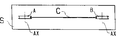
Fig. 4 illustrates a kind of known load suspension and elevator system, comprise carriage or gondola S, this carriage or gondola S can schematically illustrate with rectangular box in planar view, when considering in a longitudinal direction, comprise a transverse axis Ax at each end place, these two axle Ax parallel and be level and carry pulley A respectively, B, this system also has the cable C that is used to hang carriage S, this cable C is fixed on upper point Pf, this upper point is arranged on the top of carriage S one end along vertical direction, cable C walks around two pulley A of carriage, B also is wound in capstan winch T subsequently, and this capstan winch T is fixed on along vertical direction and is arranged on the point of carriage S other end top.
Fig. 4 illustrates carriage S with diagrammatic elevational view, and Fig. 5 illustrates corresponding carriage with planar view.Substitute gondola, also can be provided with and be used for described carriage such as structures such as jacking floor beams.
In the relevant hereinafter description of the invention, cable and pulley only are shown with graphic simplicity.Should be appreciated that the axle and the carriage of the pulley of supported and suspended cable is integrated into one to guarantee its vertical suspension and to move.Therefore, the system of Fig. 4 mentioned above will be represented by the scheme drawing of Fig. 6.
Relate to hereinafter in the explanation of pulley hand of rotation, always be associated with moving downward of its and pay attention to.
Two kinds of motion conditions of each pulley must be considered.
A) can consider a kind of so locational system of balance quiescent levels that is in, the load that wherein puts on the carriage S is assigned to each end of carriage with being equal to, and supposes that the deadweight of carriage also distributes with being equal to.In the case, if the capstan winch T pine that for example is positioned at carriage S left end top is around cable C, this carriage S moves down, and keeps its level attitude simultaneously, driven two pulley A, B rotate with equidirectional by the motion of cable C, that is to say that both will rotate with anticlockwise direction (SIA).If capstan winch T is positioned at opposite end top, promptly be positioned at the right-hand member top, both will in the opposite direction rotate to move downward two pulley A, B for carriage S same, (SDA) along clockwise direction promptly.This comparison is in Fig. 7 and shown in Fig. 8, and Fig. 7 represents that capstan winch T is set at the situation of carriage S left end top, and Fig. 8 represents that capstan winch T is set at the situation of right-hand member top.
In Fig. 7 and Fig. 8 and accompanying drawing subsequently, for motion conditions described above, the hand of rotation of each pulley is represented with solid arrow.
B) if now, under capstan winch T keeps static situation, originally the load of balance is moved towards the left end of carriage S, this end downward power of will bearing makes carriage produce so, this will make two pulley A and B on the cable C that keeps static roll, and feasiblely will move down by the left chain wheel A of this power.At opposite side, the pulley B that is arranged on right-hand member will move up, because the whole length of cable C is maintained fixed, and the length that interconnects the cable sections of two pulley A and B also is maintained fixed, and vertical right-hand member cable sections must shorten.
During it moved downward, the left end pulley A that rolls on static cable C will be with the rotation of promptly opposite with the direction SIA direction of direction (SDA), and pulley A is in this SIA direction rotation of the effect that moves downward lower edge that is arranged at the capstan winch T above it.In Fig. 9, shown situation corresponding to the load motion process that left end moves in figure.In contrast, if before at the situation b of indication above) under, this same left end pulley is positioned at the fixedly below of hitch point Pf, and capstan winch is arranged on carriage S other end top, this pulley A is when it rolls downwards so, to on the effect lower edge of load displacement and the equidirectional of before under capstan winch T acts on downwards, having been addressed, (SDA) move, as shown in figure 10.In fact, in situation about considering, play a role being relatively fixed a little in view of capstan winch T does not move and resembles, the side at capstan winch place is no longer relevant.
In Fig. 9 and 10 and thereafter in the accompanying drawing, for top involved motion conditions, the hand of rotation with dashed lines arrow of each pulley is represented.
In the case, that yes is identical for the direction of pulley rotation, and irrelevant with the carrier end at capstan winch T place, and when the motion of pulley be when being caused by capstan winch rotation institute, the direction of pulley rotation is reversed by the carrier end at change capstan winch place.
C) thereby can reach a conclusion; There are two kinds of possible system motion conditions:
1/ 1 kinds of conditions, wherein moving produces under the effect of capstan winch T, and cable C causes the rotation (solid arrow) of pulley A and B by its motion,
2/ another kind of condition, wherein capstan winch remains static, when load towards carriage one end moves time motion by pulley A and B on static cable C rolling and produce (dotted arrow).
Under second kind of situation, for along with first kind of condition under the identical vertical movement of direction, the hand of rotation of pulley A or B for the pulley that is arranged on fixing hitch point end place will with first kind of condition under identical, and for the pulley that is arranged on capstan winch end place, be in opposite sense.
Certainly, when carriage descend by capstan winch T or uphill process in load on the carriage when mobile, these two kinds of conditions may occur simultaneously with array mode.
The system that II/ develops by the cable that is multiplied
People wish to replace single cable that described system is installed by two cables C1, C2.This allows to pass through only two four of capstan winch T1, T2 actuatings and hangs cable sections, and the safety that therefore has been multiplied.
If cable is installed with being equal to, its result is with same as described above.Figure 11 illustrates this system, and this system is the pattern that doubles of system shown in Fig. 8.
If the capstan winch T2 of the second cable C2 is set at the opposite side of the first capstan winch T1, the motion of carriage S will be identical with aforementioned two kinds of operating conditionss once more, but under the vertical mobile situation that produces by capstan winch T1, T2, for the vertical moving direction identical with aforementioned system, the hand of rotation of each pulley A ', the B ' related with the second cable C2 will be opposite with the hand of rotation of pulley A that is positioned at the last corresponding position of the first cable T1 or B.In other words, coaxial pulley A, A ' and B, B ' (each is associated with different cables) rotation in the opposite direction each other.In the case, coaxial pulley A, A ' and B, B ' must be mounted freely on their the axle Ax.Figure 12 illustrates this system.
In all cases, each capstan winch certainly must be with the vertical movement that same line speed is reeled or pine is fit to the acquisition carriage around cable.
III/ is by making one in two cables to twist around the system that develops
The position that the objective of the invention is stabilizer bracket when its load is moved allows two cables to move up or down simultaneously under the capstan winch effect separately at it simultaneously.
In order to realize this effect, as shown in figure 15, in two cables at least one is by walking around it at least two pulley A2 that are positioned on each Ax of carriage, A3 and B2, B3, promptly walk around at least four pulleys, and by the strand around, so that obtain a cable loop, make on one and identical axle Ax, guarantee the coaxial pulley A1 on a pulley being associated around cable with strand (motion downward or upward) and non-strand wraparound road under the same function of two capstan winches, B1 is along the rotation of identical direction, and by the eccentric load restriction when pulley rolls on static cable along rotating around the opposite direction of the hand of rotation of the pulley in cable loop with non-strand.So purpose of the present invention realizes by these two pulleys of interlocking.
Pulley A1, the A3, B1, the B3 that are arranged on vertical cable sections lower end are known as " head sheave ", and other pulley A2, B2, promptly by one of horizontal cable sections only for the interconnective pulley of another pulley, be called " intermediate pulley ".
The left end pulley (being direct suspension) of simple cable is known as pulley A1, and strand is known as pulley A2 around the middle left end pulley of cable, and strand is known as A3 around the left end pulley of cable.Corresponding label will be used for the right-hand member pulley.
Non-strand is known as " simple cable " around cable C2.
A/ under capstan winch keeps static condition, the banking motion under the Eccentric Load on the load support
See that for such motion, the position of capstan winch T1 and T2 is inessential.Therefore, for single system, suppose that two capstan winch T1, T2 are positioned at same side, for example right-hand member, and strand interconnects pulley A2, A3 and B2, B3 and does not have the intersection of horizontal cable sections around cable, as shown in figure 13, and considers the example that load is moved towards left end.
See that eccentric when mobile on loading on carriage, the head sheave A1, the A3 that are arranged on same side (therefore coaxial and directly hang from an attachment point or from capstan winch) are impelled the hand of rotation identical to rotate with B1, B3.For example, move to the left also thereby move downward for load, two pulley A1 and A3 will rotate with the SDA direction.Intersect around the horizontal cable sections of cable by the strand that makes the Figure 13 between pulley A2, B2 and the B3 as shown in figure 14, the hand of rotation of pulley A2 will be oppositely to obtain the hand of rotation of SIA.
If pulley A1 and A2 by interlocking, can realize desired stablizing effect, because these two pulleys, each is associated with different cable loop, so can be subjected to equating under the effect that load on the carriage is moved and the constraint of opposite torque.For reaching this effect, the coaxial pulley of interlocking must have identical full diameter.
Word " intersection " refers to, a horizontal cable sections is moved towards the upside of an intermediate pulley from the downside of a head sheave, next laterally cable sections is moved towards the upside of another intermediate pulley from the downside of described intermediate pulley, and follow-up traversing section is the downside that moves towards other end pulley from the downside of another intermediate pulley.
B/ is by the vertical movement of the caused carriage of capstan winch work (central loading)
Make the hand of rotation of pulley A2 reverse by intersecting by means of each traversing section that makes strand around cable, when its when on fixed cable C1, rolling under the situation that load is moved, its hand of rotation is reversed, but under the effect of the cable C1 of capstan winch T1, its hand of rotation also is reversed, and described capstan winch is arranged on the top of the opposite end of this pulley (left side among the figure) in selected example.This hand of rotation thereby opposite with the hand of rotation of pulley A3, and thereby opposite with the hand of rotation of pulley A1 because two capstan winches are arranged on the top of carriage same side.Thereby the situation of Fa Shenging is thereupon, and by interlocking pulley A1 and A2, the vertical movement of carriage no longer may occur.
In order under the combined action of two capstan winches, to rebulid identical hand of rotation, the other end that must correspondingly transfer to carriage in two capstan winches for pulley A1 and A2.For example, the capstan winch of simple cable C2 is transferred to left end.By this modification, will be given birth to oppositely at the hand of rotation of capstan winch effect lower sheave A1, as what above explained, a head sheave is arranged on attachment point end or capstan winch end and rotation in the opposite direction according to it under the effect of its capstan winch cable.This system is illustrated among Figure 15.
Therefore, pulley A1 will rotate under the same function of two capstan winch T1 and T2 in the same direction and with identical speed with A2.But they are kept within bounds and contrarotation under the situation about moving loading on the carriage.
Correspondingly, they are interlockable so that the realization expected result promptly prevents the carriage any trend of bevelled longitudinally basically, keep the normal vertical shifting of carriage by capstan winch T1, T2 simultaneously.This interlocking of pulley schematically shows in Figure 15 with the heavy solid line that connects pulley A1 center and pulley A2 center.This interlocking can or fix on their common axis by the hublock with pulley A1, A2, and pulley A3 is free to rotate on this axle, or realizes by the pulley that use has two grooves.
Understandablely be, no matter load left or move right, its result is identical.Also understandable is that as long as two capstan winches are positioned at the opposite end of carriage, this result is identical, and no matter twists left end top or the right-hand member top that is arranged on carriage around the capstan winch of cable or simple cable.Therefore, by twisting around the capstan winch of cable but not the capstan winch of simple cable be installed on the carriage left end and can realize identical result.
IV/ is by providing the system of two strands around cable is developed
See that in described system, the single pulley in hanging element 1/4th circles of only having reeled, two pulleys provides cable/pulley friction with the balance eccentric load on each of two pulley A1, the B1 in simple cable loop.Particularly under the situation that cable/pulley is installed, advantageously the arc length that cable is engaged on pulley is to maximum, to improve cable/pulley friction force that system's proper operation is relied on.
For reaching this effect, two cable loops preferably by strand around so that obtain system shown in Figure 16.
This system also provides the more more options of interlocking pattern, replaces three pulleys because it is provided with four pulleys on each Ax.
In this system and the system at accompanying drawing thereafter, the right-hand member intermediate pulley of twisting in addition around cable is designated as B0, and A0 is corresponding left end pulley.
For better in the operation of the two ends of gondola balanced system, particularly irrelevant with the sense of displacement of load, advantageously except the interlocking of pulley A1 and A2 also by the interlocking of pulley B0 and B2 is provided on the common axis that B0 and B2 is locked in they, this will allow to significantly improve cable/pulley friction force.Pulley B1 and B3 rotate freely maintenance, and the pulley A0 among Figure 17 also is the same with A3.
Possible interlocking pattern is represented in Figure 18-22.Preferably, select system shown in Figure 19, wherein be provided with at the two ends of gondola and reach three and can be interlocked together adjacent pulleys to obtain desired effect, perhaps it also can replace with the pulley with triple grooves.
In Figure 17-22, the interlocking of coaxial pulley is as representing with heavy solid line among Figure 15.Except that the interlocking of pulley, the embodiment of Figure 19 is corresponding with Figure 18 embodiment; And except that the interlocking of pulley, the embodiment of Figure 21 is corresponding with the embodiment of Figure 20.
The V/ disengagement gear
If level attitude changes, advantageously be convenient to allow rebulid the operation of the level attitude of load support.This change, for example after predetermined operation time period, when hanging element has had gradually slip in pulley groove, particularly in high capacity continually under the same side out-of-position effect of carriage, under the situation of hanging element and pulley frictional engagement, cause.In addition, may wish the pre-determined tilt of load support is adjusted, if when particularly load support comprises jacking floor beam.For reaching this effect, the present invention combines any system that is used for separating selectively coaxial interlocking pulley.In context, can suppose that coaxial interlocking pulley fixes on by the hublock with them on their common axis to interconnect that non-interlocking pulley then rotates freely on same axis.So this disengagement gear will be made of known devices, so that separate common interlocking and with the wheel hub of the coaxial pulley of these rotations from their axle.
This disengagement gear is shown in Figure 23 A and the 23B, and they all illustrate pulley A1, A2 and A3 on the left end shaft Ax that is installed in Figure 15.In these figure, left end shaft Ax rotates in two plain bearing R, R, and antifriction-bearing box R, R are installed in and are attached in the housing CA of carriage S below the carriage S.The pulley A1 that is subordinated to simple cable loop C2 is fixed to an Ax by key CL and goes up with its rotation.Be installed on the Ax by antifriction-bearing box R2, R3 respectively around gas pulley A2 that cable C1 is associated and each among the A3 with strand.According to Figure 23 A, pulley A2 and pulley A1 be by being clamped in the stop screw V interlocking on the Ax, make this pulley A2 be fixed and with axle Ax rotate and therefore with the pulley A1 interlocking that is bonded on this Ax.This stop screw V is also as disengagement gear, because after unclamping from axle Ax and being disengaged, it allows pulley A2 rotating freely on axle Ax.
Figure 24 A is illustrated in has pulley A0, the A1 of two strands on the left end shaft Ax embodiment illustrated in fig. 19 of cable loop C1 and C2 and the mutual locking of A2.The pulley A0 and the A1 that are associated with cable C2 interlock by using a sister block, and pulley A2 locks onto on the Ax by stop screw V, and thereby with sister block A0-A1 interlocking.For pulley A2 is separated from sister block A0-A1, stop screw V is released and be disengaged (seeing Figure 24 B) with axle Ax.
The VI/ anti-drop device
According to a certain embodiments, maybe advantageously remedy the consequence of may lose efficacy (the breaking) of one of two hanging elements.This breaks can be influential to balanced system, and having under the situation of eccentric load, and carriage may tilt to suddenly and be close near vertical position.For avoiding this result, the present invention also is equipped with anti-drop device in addition in suspension, this anti-drop device is engaged on the relevant end axle, when exceeding the predetermined acceleration and/or the rotative speed limit at the acceleration/accel that rotatablely moves, particularly under the situation that one of two hanging elements break, with its prevention.
Figure 25 A illustrates the embodiment shown in Figure 19, has the anti-drop device DA that is arranged on each end axle Ax.Each anti-drop device DA is supported by the respective housings CA of A type pulley and Type B pulley respectively, and among these anti-drop devices DA each comprise stationary housing BT and by key be connected in that corresponding axis Ax goes up and with the disc-shaped element D of its rotation.Disc-shaped element D is provided with a plurality of groove E and ball or roller BI at its periphery and is received within the groove E.If one in the cable breaks, for example be cable C1, under the acceleration/accel effect of axle Ax and disc-shaped element D, the relative groove E of this ball or roller BI is forced to radially outward and merges with the internal interface of housing BT and to prevent being further rotated of an Ax.Figure 25 B illustrates device among Figure 25 A with planar view, and this device has respectively the anti-drop device DA that is fixed to housing CA in the end of the axle Ax of two pulley A2, A3 that separate and B0, B1 one side.Figure 24 A and 24B also illustrate the anti-drop device DA that is installed on the back plate PL that is welded to housing CA.
The VII/ preferred embodiment
According to preferred embodiment shown in Figure 26, the capstan winch that replaces the every end vertical setting in top of carriage, promptly amount to two capstan winches, two current vertical section of system can be wound onto on two head rolls or the pulley 10,11, and head roll or pulley 10,11 are installed on the axle drive shaft of single-motor M by key.
For reaching this effect, deflection sheave 12,13 is walked around in described two sections upper ends at its vertical extension, and on even keel extends toward each other and walks around another deflection sheave 14 once more subsequently, 15, form the direction that extends in parallel of closely approaching each other hanging element, with allow they be wound up into simultaneously two of single capstan winch 16 rotate reel or driver element on or from it pine around.Figure 26 illustrates an example of this device, and it has preferred multiple twin around funicular system.
This device can be installed in and shake on the control carriage, to allow carriage cross motion takes place except vertical movement.In addition, this device can have the anti-fall or anti-inclination safety apparatus that is arranged on the legacy system.
System mentioned above can replace cable and use belt, and pulley has the groove of suitable shape.Also can replace cable and replace pulley with chain with sprocket wheel.This carriage can have for example gondola form or side platform form for building, cable or be equal to hanging element thereon by the suitable device guiding that is arranged on end stirrup (endstirrups) upper end.It also can be used to the vertical movement of jacking floor beam, or any other has the load support of using suitable constructions of the present invention.
Claims (8)
1. a suspension and elevator system that is used for load support, be applied to two opposed ends of described load support, described load support is hung by four suspension sections that are made of at least two hanging elements at least, each hanging element is hung towards another carriage end towards one of described carriage end and from the drive element of bont from an attachment point by walking around circular hanging element steering support member, described circular hanging element steering support member rotates with hanging element and is installed on two parallel shafts, every end of load support has one of described axle of installing towards described respective end, and the circular hanging element steering support member towards the setting of load support same end is installed on the same axis
It is characterized in that, each hanging element is connected to the bont that is associated with it that is positioned at the load support end, another hanging element is connected to another bont of load support opposed end, at least one hanging element twists in succession to be walked around towards the circular hanging element steering support member at least two centres of each load support end so that suitable along with a crossedpath, make on one of described end axle, under the same function of two bonts that are associated with described hanging element, at least one the circular hanging element steering support member that is associated with a described hanging element with and at least one coaxial circular hanging element steering support member of being associated of another hanging element along identical direction rotation, thereby when their common axis is subjected to being forced to when downward with the irrelevant identical power of the effect of bont, the torque that equal and opposite in direction and direction are opposite is respectively applied on described two coaxial circular hanging element steering support members, and described two coaxial circular hanging element steering support members have identical full diameter and interlocking aspect rotation, make described two the coaxial circular hanging element steering support members rotation in opposite direction cause by described power be prevented from basically, thereby do not influence of the effect of the centre portion of bont by hanging element described two coaxial circular hanging element steering support members.
2. system according to claim 1, it is characterized in that, two hanging elements all twist and wind a crossedpath of walking around towards the circular hanging element steering support member at least two centres of each end of load support to follow separately, prevent their rotations in opposite direction at least two coaxial circular hanging element steering support members directly are linked together, make their rotations separately locate interlockings in two ends of load support by place, two ends at load support.
3. system according to claim 1, it is characterized in that, two hanging elements all twist and wind a crossedpath of walking around towards the circular hanging element steering support member at least two centres of each end of load support to follow separately, prevent their rotations in opposite direction at least three adjacent coaxial circular hanging element steering support members directly are linked together, make their rotations separately locate interlockings in two ends of load support by place, two ends at load support.
4. according to the described system of above-mentioned any one claim; it is characterized in that; comprise a device that is used to separate the coaxial circular hanging element steering support member that common interlocking gets up; so that make they selectively and temporarily one independent with another or wherein some and other rotations; and allow to handle them to rebulid the level attitude of load support, perhaps adjust their expection and tilt.
5. according to each described system among the claim 1-3, it is characterized in that, described hanging element is and the cable or the belt of the pulley collaborative work with respective perimeter shape that the friction coefficient that described cable or belt have allows to engage with described pulley under the condition that can not produce slippage basically.
6. according to any one described system in the claim 1 to 3, it is characterized in that described hanging element is made of chain, described circular hanging element steering support member is made of sprocket wheel, and the tooth portion of this sprocket wheel is corresponding with the structure of described chain.
7. according to each described system among the claim 1-3, it is characterized in that, the top that each of hanging element that is connected to bont hangs section hangs a section lateral deflection towards another, so close toward each other two hang section once more deflection be wound onto on two winding elements with single actuating device interlocking to allow them rebuliding its relative to each other portion that extends in parallel on same direction.
8. according to each described system among the claim 1-3, it is characterized in that, comprise that at least one can be engaged in the anti-drop device on one of described end axle, brake described end axle when exceeding the preset limit of acceleration/accel and/or rotating speed with the acceleration/accel that rotatablely moves at it.
Applications Claiming Priority (2)
| Application Number | Priority Date | Filing Date | Title |
|---|---|---|---|
| LU91026A LU91026B1 (en) | 2003-06-13 | 2003-06-13 | System for lifting and stabilizing a suspended load support. |
| LU91026 | 2003-06-13 |
Publications (2)
| Publication Number | Publication Date |
|---|---|
| CN1594063A CN1594063A (en) | 2005-03-16 |
| CN100398429C true CN100398429C (en) | 2008-07-02 |
Family
ID=33297414
Family Applications (1)
| Application Number | Title | Priority Date | Filing Date |
|---|---|---|---|
| CNB2004100766638A Expired - Fee Related CN100398429C (en) | 2003-06-13 | 2004-06-14 | Hoisting and stabilization system for suspended load support |
Country Status (9)
| Country | Link |
|---|---|
| US (1) | US7070171B2 (en) |
| EP (1) | EP1486452B1 (en) |
| CN (1) | CN100398429C (en) |
| AT (1) | ATE404487T1 (en) |
| CA (1) | CA2470266A1 (en) |
| DE (1) | DE602004015676D1 (en) |
| ES (1) | ES2312926T3 (en) |
| HK (1) | HK1073096A1 (en) |
| LU (1) | LU91026B1 (en) |
Cited By (1)
| Publication number | Priority date | Publication date | Assignee | Title |
|---|---|---|---|---|
| CN104627884A (en) * | 2015-01-23 | 2015-05-20 | 无锡华东重型机械股份有限公司 | Steel wire rope deflection winding mechanism |
Families Citing this family (16)
| Publication number | Priority date | Publication date | Assignee | Title |
|---|---|---|---|---|
| AU2002354242A1 (en) * | 2002-12-19 | 2004-07-14 | Hhh Manufacturing Co. | Electric hoist |
| US7407150B1 (en) | 2007-08-21 | 2008-08-05 | Bellantoni John F | Self-stabilizing suspension and hoisting system |
| AT507373B1 (en) * | 2008-10-09 | 2010-12-15 | Amst Systemtechnik Gmbh | MOTION AND ORIENTATION SIMULATOR |
| US20100248603A1 (en) * | 2009-03-31 | 2010-09-30 | Decastro Eugene | Retrofit Fume Hood Drive Assembly |
| WO2011078846A1 (en) * | 2009-12-21 | 2011-06-30 | Aho Melvin S | Improved self-propelled transportable rock picker |
| US8070134B1 (en) | 2011-03-04 | 2011-12-06 | Bellantoni John F | Stabilized single-motor lift system without top rails |
| CN102506136B (en) * | 2011-09-23 | 2015-04-15 | 三一汽车制造有限公司 | Rope driving mechanism frame, rope driving mechanism and engineering machinery |
| CN103963047B (en) * | 2014-05-05 | 2015-10-28 | 西安电子科技大学 | With the rope traction parallel robot device of rotation preventing mechanism |
| US20150327935A1 (en) * | 2014-05-19 | 2015-11-19 | University Of Dundee | Medical Equipment Support System |
| CN110436362B (en) * | 2019-06-28 | 2021-11-12 | 佳力机械股份有限公司 | Lifting hook stabilizing system of ring chain hoist and hoisting equipment |
| CN110589523A (en) * | 2019-09-03 | 2019-12-20 | 中国航空工业集团公司西安飞机设计研究所 | Aviation cargo handling device |
| CN110835052B (en) * | 2019-10-31 | 2021-09-28 | 上海振华重工(集团)股份有限公司南通分公司 | Turnover process in ultra-large type rail crane girder structure workshop |
| CN112110336B (en) * | 2020-09-21 | 2022-11-25 | 中国建筑第八工程局有限公司 | Device for mounting steel beam on floor and construction method thereof |
| CN113562636B (en) * | 2021-07-27 | 2023-11-24 | 湖北誉江船舶制造有限公司 | Small-sized ship lifting frame used on ship |
| US11608252B1 (en) * | 2022-02-15 | 2023-03-21 | Innovative Minds, LLC | Damper systems for suspended loads |
| CN116281495B (en) * | 2023-04-12 | 2024-01-02 | 杭州欣源电梯部件有限公司 | Elevator car wire rope locking structure |
Citations (6)
| Publication number | Priority date | Publication date | Assignee | Title |
|---|---|---|---|---|
| DE2165268A1 (en) * | 1971-12-29 | 1973-07-12 | Krupp Gmbh | CRANE HOIST |
| US3801070A (en) * | 1969-12-05 | 1974-04-02 | Piasecki Aircraft Corp | Hoist system |
| JPS5253349A (en) * | 1975-10-27 | 1977-04-28 | Hitachi Ltd | Rock preventing apparatus for hung device from crane |
| US4214664A (en) * | 1978-08-24 | 1980-07-29 | The Alliance Machine Company | Crane safety reeving |
| DE4005194A1 (en) * | 1989-02-17 | 1990-08-23 | Caillard | Method holding load of bridge crane - involves carriage with two parallel winding drums and set of guiding pulleys |
| US5074528A (en) * | 1989-07-03 | 1991-12-24 | Harnischfeger Corporation | Redundant crane reeving apparatus |
Family Cites Families (7)
| Publication number | Priority date | Publication date | Assignee | Title |
|---|---|---|---|---|
| BE664298A (en) * | ||||
| DE1207584B (en) * | 1963-02-25 | 1965-12-23 | Soc D Forges Et Ateliers Du Cr | Winch with two drums arranged on a traveling crane |
| US3263965A (en) * | 1964-08-31 | 1966-08-02 | Dominion Bridge Co Ltd | Dual-speed, dual-load hoist arrangement |
| DE3323138A1 (en) * | 1983-06-27 | 1985-01-10 | Helmut Dr. 8031 Alling Forster | GRAVITY RELIEF DEVICE |
| US5772360A (en) * | 1997-05-19 | 1998-06-30 | Wood, Ii; Donald M. | Topless watercraft lifting apparatus with a differential gearing system |
| US6926103B1 (en) * | 2001-07-02 | 2005-08-09 | Itrec B.V. | Splittable block on a derrick |
| US6827334B2 (en) * | 2001-12-14 | 2004-12-07 | Mhe Technologies, Inc. | Lifting arrangement for overhead traveling cranes |
-
2003
- 2003-06-13 LU LU91026A patent/LU91026B1/en active
-
2004
- 2004-06-03 DE DE602004015676T patent/DE602004015676D1/en active Active
- 2004-06-03 ES ES04102502T patent/ES2312926T3/en active Active
- 2004-06-03 EP EP04102502A patent/EP1486452B1/en not_active Not-in-force
- 2004-06-03 AT AT04102502T patent/ATE404487T1/en not_active IP Right Cessation
- 2004-06-08 CA CA002470266A patent/CA2470266A1/en not_active Abandoned
- 2004-06-09 US US10/864,047 patent/US7070171B2/en not_active Expired - Fee Related
- 2004-06-14 CN CNB2004100766638A patent/CN100398429C/en not_active Expired - Fee Related
-
2005
- 2005-07-06 HK HK05105665A patent/HK1073096A1/en not_active IP Right Cessation
Patent Citations (6)
| Publication number | Priority date | Publication date | Assignee | Title |
|---|---|---|---|---|
| US3801070A (en) * | 1969-12-05 | 1974-04-02 | Piasecki Aircraft Corp | Hoist system |
| DE2165268A1 (en) * | 1971-12-29 | 1973-07-12 | Krupp Gmbh | CRANE HOIST |
| JPS5253349A (en) * | 1975-10-27 | 1977-04-28 | Hitachi Ltd | Rock preventing apparatus for hung device from crane |
| US4214664A (en) * | 1978-08-24 | 1980-07-29 | The Alliance Machine Company | Crane safety reeving |
| DE4005194A1 (en) * | 1989-02-17 | 1990-08-23 | Caillard | Method holding load of bridge crane - involves carriage with two parallel winding drums and set of guiding pulleys |
| US5074528A (en) * | 1989-07-03 | 1991-12-24 | Harnischfeger Corporation | Redundant crane reeving apparatus |
Cited By (2)
| Publication number | Priority date | Publication date | Assignee | Title |
|---|---|---|---|---|
| CN104627884A (en) * | 2015-01-23 | 2015-05-20 | 无锡华东重型机械股份有限公司 | Steel wire rope deflection winding mechanism |
| CN104627884B (en) * | 2015-01-23 | 2017-01-25 | 无锡华东重型机械股份有限公司 | Steel wire rope deflection winding mechanism |
Also Published As
| Publication number | Publication date |
|---|---|
| EP1486452A2 (en) | 2004-12-15 |
| DE602004015676D1 (en) | 2008-09-25 |
| EP1486452B1 (en) | 2008-08-13 |
| EP1486452A3 (en) | 2006-04-19 |
| ATE404487T1 (en) | 2008-08-15 |
| CN1594063A (en) | 2005-03-16 |
| US7070171B2 (en) | 2006-07-04 |
| US20040251455A1 (en) | 2004-12-16 |
| LU91026B1 (en) | 2004-12-14 |
| HK1073096A1 (en) | 2005-09-23 |
| CA2470266A1 (en) | 2004-12-13 |
| ES2312926T3 (en) | 2009-03-01 |
Similar Documents
| Publication | Publication Date | Title |
|---|---|---|
| CN100398429C (en) | Hoisting and stabilization system for suspended load support | |
| CN102387977B (en) | Elevator governor | |
| US8020670B2 (en) | Arrangement for equalizing elevator rope force and elevator | |
| US20030019828A1 (en) | Hoist apparatus using a counter weight technology | |
| CA1169365A (en) | Drive system for wire rope hoists | |
| US6688582B1 (en) | Force balancing device for a hoist with two traction cables and hoist fitted with such device | |
| US7500575B2 (en) | Crane trim, list, skew and snag protection system | |
| US3945504A (en) | Anti-sway system for a spreader suspended from a crane | |
| JP7022664B2 (en) | Hook device and crane | |
| JPH0742063B2 (en) | Elevator drive system | |
| JPWO2007069311A1 (en) | Elevator equipment | |
| JP2003040577A (en) | Bridge crane | |
| KR102077124B1 (en) | Roping device for balance weigght and roping device for elevator including the same | |
| CN107792749A (en) | Elevator | |
| EP3097042B1 (en) | Low-construction trolley for wire rope hoist | |
| WO2003033389A1 (en) | Elevator | |
| JP4742606B2 (en) | Machine room-less elevator device | |
| JP4694507B2 (en) | Elevator equipment | |
| JP6232205B2 (en) | Elevator equipment | |
| JP4658063B2 (en) | Machine room-less elevator device | |
| JP2012020820A (en) | Elevator | |
| WO2004028948A1 (en) | Elevator equipment | |
| JPH0286588A (en) | Elevator | |
| JPH0656371A (en) | Elevator system | |
| JP2005206263A (en) | Elevator driving device |
Legal Events
| Date | Code | Title | Description |
|---|---|---|---|
| C06 | Publication | ||
| PB01 | Publication | ||
| REG | Reference to a national code |
Ref country code: HK Ref legal event code: DE Ref document number: 1073096 Country of ref document: HK |
|
| C10 | Entry into substantive examination | ||
| SE01 | Entry into force of request for substantive examination | ||
| C14 | Grant of patent or utility model | ||
| GR01 | Patent grant | ||
| REG | Reference to a national code |
Ref country code: HK Ref legal event code: GR Ref document number: 1073096 Country of ref document: HK |
|
| C17 | Cessation of patent right | ||
| CF01 | Termination of patent right due to non-payment of annual fee |
Granted publication date: 20080702 Termination date: 20130614 |