Background technology
Device connector can arbitrarily make lead be connected and throw off with device or other equipment, and device connector comprises two parts: connector and device intake.Common connector plug form, and device intake socket type.Usually lead is used for the power delivery auto levelizer with for example AC or DC electric current.Perhaps, lead-in wire is as the conductor of data transmission.
Usually be electrically connected with plug and socket, the combination of plug and socket must be that hand is not too required great effort and just can be extracted from socket with plug insertion socket and with plug, makes it easy to connect and throw off.The power that plug and socket is thrown off required minimum is called removal force.Apply removal force with pulling force, pulling force is the power that is added in the combination of plug and socket, and the connection that makes plug and socket with pulling force separately.Although plug is thrown off from socket easily,, when operating equipment, also may exist the pulling force that requires plug to bear to want obvious situation greater than removal force.Can satisfy these multi-form conflicting requirements by retaining element is set, described retaining element is operated to be independent of with the fixed effect that combination was obtained of the multi-form plug and socket of independently finishing.
Usually, plug and corresponding socket constitute the engagement that can slide mutually, and the jack degree of depth of socket is the straddle length of plug at least.Straddle can stretch out from supporting member, perhaps and supporting member form an integral body.Straddle can constitute with conductor, for example, and metal, or some has the combination of the supporting member of conducting element.Jack is encapsulated in the insulating component usually.The friction bed knife is arranged between the jack of straddle and its correspondence.In addition, in some plug and socket structure, the encapsulation of each plug and socket has the friction bed knife.This friction bed knife is opposite with pulling force, therefore, helps raising to make plug and socket throw off desired removal force value.
Transmit in the common version of electric energy between socket on the Australian wall and the lead-in wire, correlation standard, in plug with 3 one group straddle.A straddle is as " ground wire ", and all the other two straddles are respectively " live wires " and " zero line ".The rectangle that straddle is normally flat, its size be approximately 1.5mm thick * 20mm length * 5mm is wide.Straddle is arranged on around the central point." ground wire " straddle almost radially is provided with respect to central point, and all the other two straddles are by roughly tangential direction setting.Prong configuration in the socket wants to insert the straddle of plug, the corresponding straddle of jack.In such a way, unique orientation is that plug and socket is meshed together.Australia transmits in the another kind of general mode of electric energy, only with two straddles, has omitted the straddle of ground connection.In some European countries, with two one group cylindrical straddle.Columniform ground connection straddle and two general flat rectangle straddles are arranged in that U.S.'s plug is general.Also has the configuration of other known straddles and socket.
Tie point between lead-in wire and the electric equipment has international standard.These standards generally include the removal force to the regulation of plug and socket combination.
In the other forms of power line, an end of lead-in wire has wall socket engagement plug, at the other end device engagement shell is arranged.Fig. 1 demonstrates existing device engagement shell 10.Device engagement shell 10 is rectangle normally, and its first end is connected to lead-in wire, and second end 12 is connected with equipment.Second end 12 has irregular " being squeezed " hexagonal external feature usually, and the length of being somebody's turn to do " part is squeezed " profile roughly is 19mm, and the length of device engagement shell 10 roughly is 55mm.In the use, device engagement shell 10 is positioned at the front that recessed hexagonal socket 20 is arranged, and socket 20 is positioned at the outer side edges of equipment 5.Fig. 2 demonstrates existing socket.The length that device engagement shell 10 can insert hexagonal structure usually is about 19mm.3 flat rectangle straddles 25 are arranged in the socket 20 of equipment, and straddle 25 slides into corresponding jack 15 in the device engagement shell 10.With providing bed knife between the socket 20 of the frictional force between the mating surface for the device engagement shell 10 of lead-in wire and equipment, for example be between the inwall 27 of the outer wall 17 of (i) device second end 12 of meshing shell 10 and the socket 20 in the equipment between the described mating surface; (ii) between the inwall of the outer surface of straddle 25 and jack 15.Under the situation of the plug and socket shown in Fig. 1 and 2, because the bed knife that has only the friction between plug and the socket to cause, so removal force is less.
Other field also can be used the configuration of plug and socket.For example, in data communication field, the plug and the corresponding socket that comprise fixture are set by telephone network.In Fig. 3 and the configuration shown in Figure 4, Fig. 3 a, 3b, 3c show front view, end view and the top view of existing plug 30 respectively.Fig. 4 a and Fig. 4 b show the front view and the end view of existing socket 40 respectively.This plug and socket combination is referred to as RJ series connector usually.
Plug 30 comprises cantilever 32, its relative fulcrum rotation when cantilever 32 is stressed.Cantilever 32 flexibly is biased in the upper position.As shown in Fig. 3 c, cantilever 32 has wide part 34 and narrow part 36.Joint between wide part 34 and the narrow part 36 has a pair of shoulder district 38.
Hold plug 30 in the socket 40 slidably, therefore, the shape of the shape of socket 40 and plug 30 is roughly complementary.Socket 40 comprises the shoulder 48 that is suitable for shoulder 38 engagement of plug 30.When plug 30 inserted socket 40, cantilever 32 must rotation enter following position.In case plug 30 inserts socket 40 fully, cantilever 32 rebounds and enters upper position, and each shoulder 38 and shoulder 48 are meshing with each other.Therefore plug 30 is fixed in the socket 40.The engagement of plug 30 and socket 40 can not thrown off, and compresses into the position of bottom up to cantilever 32, and two shoulders 38 and 48 engagement are just thrown off.Under some state, excessive pulling force is added on lead-in wire or the plug 30, cantilever 32 is fractureed by permanent deformation or damages.
Fig. 5 and 6 demonstrates other the existing configurations that are used for plug and socket is fixed together in the data communication field.In this configuration, the straddle 54 that is arranged in plug 50 is configured to mesh slidably with the jack 64 of socket 60.In this configuration, plug 50 and socket 60 are main fixing with the screw in the plug 50 52, screw 52 and corresponding jack 62 engagements, the screw thread complementation of the screw thread of jack 62 and screw 52.In addition, frictional fit between straddle and the jack and between the respective inner surfaces of sheath 55 and socket 60.The combination of throwing off this plug and socket under the situation of at first not turning on screw 52 can damage the screwed hole of screw or their complementations, or the globality of plug and socket, or socket is fixed to the fixture of using on the equipment.
Being used for fixing the problem that the existing configuration of connector and device intake exists is, removal force is too little, thereby the requirement of the mode of operation of deviating from from the device intake can not satisfy the connector of running into through regular meeting be subjected to pulling force in operating environment the time.Perhaps, removal force is too big, before connector is thrown off from the device intake connector and device intake is caused physical damage.For example, under situation about connector and device intake being fixed together with screw, other parts of connector and device intake may damage before unclamping screw.Can cause when this configuration is used for feed cable before screw unclamps, to make live wire fracture or expose, or cause the other forms of damage of device at environment.Another undesired consequences that should also be clear that this configuration is that connector may disconnect with the feed cable that is connected, and perhaps, installs intake and separates with other parts of device.Each example that element is thrown off all can cause short circuit, perhaps, charged the end of a thread is exposed in environment, thereby produce a kind of dangerous situation, as cause device further to damage, and causes electric shock, arcing and catching fire.And, cause power line, connector, device intake or fixture damage, and cause and can not continue the state that uses again.
The device coupling part also has the additional standard of the world or national standards organizations promulgation except the universal standard, or the standard of department's (for example, being responsible to define the department of medical equipment standard) formulation, and these standards can only require that removal force reaches the application-specific requirement.For example, the standard ISO/TC 121/SC 3N 1066 of " lung ventilator and the relevant device " by name of International Organization for Standardization issue in 8 days July calendar year 2001.
In other examples, require by configured in series electric wire group, and the connection electric wire that is meshing with each other of the plug and socket by complementation, the pulling force that the plug and socket of the complementation of engagement can bear reaches the limit of regulation and does not throw off.By not with making the straddle of connection and the maximum, force that socket unclamps, the sufficiently high pulling force of the component wear of causing is not arranged, just can reach such connection.The present invention can be used for the connection of electric wire group.
The problem of above-mentioned existing plug and socket illustrated in figures 1 and 2 is, bed knife between the plug and socket is owing to the friction between the sliding engaged face of corresponding complementation produces, this bed knife can not satisfy the regulation requirement of the specified standard power of relevant industrial or equipment, for example, the scope of the specified standard power that can bear before throwing off of plug and socket is 100 to 300 newton.This example should be realized that just in order to illustrate different equipment and/or different industries have different standards.In this example, proof force is set to minimum force, for example, can prevent unexpected interruption.In some industry, have definite standard, for example, be set to 100 newton.Its reason is that plug and socket during normal use keeps connecting, and can make its disengagement and add suitable power with hand.That is to say that the user needn't apply than without the reasonable big active force of externally applied forces of auxiliary equipment possibility plug and socket being connected and throwing off.And plug and socket is not designed so that removal force surpasses the strength degree of plug and relevant electric wire.Therefore, maximum removal force for example can be set is 300 newton.
Selected objective target of the present invention is to satisfy following requirement, and the detachable electric wire that promptly has a plug for example can bear greater than 100 newton and less than 300 newton's pulling force (being defined as axial tension), and the user still can easily make plug throw off from medical equipment.
Another problem of above-mentioned existing plug and socket illustrated in figures 1 and 2 is, because the bed knife between the caused plug and socket of friction between the surface of corresponding complementary sliding engaged is unpredictable in the element of producing in batches.
Can be applied to the multiple safety and the administrative standard of plug and socket combination, the combination of single plug and socket is satisfied at country variant, the different removal force standards during distinct device is used are difficult especially.And, although a kind of standard also may allow power line or other electrical fitting electric wires permanently to be fixed on the equipment,, wish to adopt the device male part to allow power line that interchangeability is arranged from the angle of manufacturer, so that make and system configuration, to satisfy a large amount of standard-requireds.
Summary of the invention
One aspect of the present invention is will overcome or overcome problems of the prior art to small part.
The technical term of using in this specification " comprises " not having exclusiveness.That is to say that device " comprising feature a, b, c " should be understood to other features that also have except that feature a, b, c.
The technical term of using in this specification " release force " is meant connector and the required power of device intake that is fixed together by fixture of unclamping.
The plug and socket of this specification middle finger is understood to include general device male part.
By a scheme of the present invention, the manufacture method of making geometrical clamp is provided, wherein, geometrical clamp can unclamp under predetermined release force effect.
Press embodiments of the invention, be provided for the geometrical clamp of device male part, geometrical clamp can unclamp under predetermined release force effect.
In a kind of form of the present invention, a kind of device is provided, be used to pre-determine the removal force that is used for the plug and socket assembly.
In the another kind of form of the present invention, provide a kind of device, be used to pre-determine the careless or removal force unintentionally that is used for the plug and socket assembly.
By another scheme of the present invention, provide the geometrical clamp that is applicable to the engagement plug and socket.
By another embodiment of the present invention, the plug that comprises plug, socket and geometrical clamp fixation kit is provided, plug and geometrical clamp comprise be applicable to each the complementary engaging mechanism that unclamps under predetermined release force effects.
By another embodiment of the present invention, the plug that comprises plug, socket and geometrical clamp fixation kit is provided, wherein, plug comprises lug, geometrical clamp comprises the lug engaging mechanism, is applicable under predetermined release force effect to unclamp.
By another embodiment of the present invention, the change method of the release force of the plug fixation kit that comprises plug, socket and geometrical clamp is provided, and wherein, plug comprises lug, geometrical clamp includes the lug engaging mechanism of key groove, is applicable under predetermined release force effect to unclamp.This method comprises the change key groove.
By another embodiment of the present invention, the change method of the release force of the plug fixation kit that comprises plug, socket and geometrical clamp is provided, and wherein, plug comprises lug, geometrical clamp includes the lug engaging mechanism of key groove, is applicable under predetermined release force effect to unclamp.This method can comprise the elasticity that changes geometrical clamp.
The invention provides a kind of plug fixation kit, comprising: plug, this plug comprises lug; The socket that is connected with plug; And geometrical clamp, this geometrical clamp comprises the lug engaging mechanism, be used to allow predetermined release force that plug is thrown off from socket to act on the plug, this geometrical clamp is located movably with respect to socket, to move between non-plug fixed position and plug fixed position, wherein, the inclined surface of described lug engaging mechanism engages this lug, described inclined surface has an angle, and this angle determines described predetermined release force at least in part.
The present invention also provides a kind of establishing method of release force of plug fixation kit, may further comprise the steps: the socket that has plug, is connected with plug, the plug fixation kit of geometrical clamp are provided, wherein, plug comprises lug, geometrical clamp comprises the lug engaging mechanism, described engaging mechanism has a key groove, and this key groove is suitable for making plug to throw off with socket under predetermined release force effect; Select described key groove according to this predetermined release force; Can select key groove according to following formula: Fpull=Fytab/Tan X wherein, Fpull represents release force (newton); X represents key groove (degree); Fytab represents plug by the suffered power of geometrical clamp tab (supposing approximately vertical); Plug is engaged with socket; And move described lug engaging mechanism with respect to the plug and socket of described joint, to locate this key groove with respect to described lug.
The present invention also provides a kind of establishing method of release force of plug fixation kit, may further comprise the steps: the socket that has plug, is connected with plug, the fixation kit of geometrical clamp are provided, wherein, plug comprises lug, geometrical clamp comprises the lug engaging mechanism, described lug engaging mechanism has a key groove, and this key groove is suitable for allowing under predetermined release force effect plug to be thrown off from socket; Select the elastic force of this geometrical clamp according to this predetermined release force; Can select the elastic force of geometrical clamp: D=Fxtab*L^3/3*E*I according to following formula, wherein, the departure that the required geometrical clamp two ends cantilever of plug is unclamped in the D representative; The required power of Fxtab=skew cantilever beam; The L=jib-length; The Young's modulus of E=material; The I=the moment of inertia; Plug is engaged with socket; And move described lug engaging mechanism with respect to the plug and socket of described joint, to locate this key groove with respect to described lug.
The constructive method of plug fixation kit preferably allows to throw off from socket pre-determining under the release force effect plug, this method comprises the ability that reconfigures the plug geometrical clamp, therefore at least after plug under the effect of release force is thrown off, plug can reconnect to socket, and maintenance is connected up to the effect that is subjected to release force again with socket.
The method for optimizing that constitutes the plug fixation kit comprises that this assembly can make the user by applying removal force plug be thrown off from socket, and plug was thrown off required release force from socket when described removal force was significantly less than with geometrical clamp.
Description of drawings
Fig. 1 is existing plug schematic diagram;
Fig. 2 is existing socket schematic diagram;
Fig. 3 is existing plug schematic diagram;
Fig. 4 is existing socket schematic diagram;
Fig. 5 is existing plug schematic diagram;
Fig. 6 is existing socket schematic diagram;
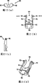
Fig. 7 (a), 7 (b) and 7 (c) are the schematic diagrames by the chuck of the embodiment of the invention;
Fig. 8 (a), 8 (b), 8 (c) and 8 (d) are the different views by the plug of the embodiment of the invention;
Fig. 9 (a), 9 (b), 9 (c) and 9 (d) are the schematic diagrames by the geometrical clamp of the embodiment of the invention;
Figure 10 (a) and 10 (b) are the schematic diagrames of plug, geometrical clamp and chuck component by the embodiment of the invention;
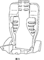
Figure 11 is the schematic diagram of plug, geometrical clamp and chuck component by the embodiment of the invention;
Figure 12 is the schematic diagram of plug, geometrical clamp and chuck component by the embodiment of the invention;
Figure 13 (a), 13 (b) and 13 (c) are the schematic diagrames by the chuck of the embodiment of the invention;
Figure 14 (a), 14 (b) and Figure 14 (c) are the schematic diagrames by the plug of the embodiment of the invention;
Figure 15 (a), 15 (b), 15 (c) and 15 (d) are the schematic diagrames by the geometrical clamp of the embodiment of the invention;
Figure 16 (a) and 16 (b) are the schematic diagrames of plug, geometrical clamp and chuck component by the embodiment of the invention;
Figure 17 is the schematic diagram of plug, geometrical clamp and chuck component by the embodiment of the invention;
Figure 18 is the schematic diagram of plug, geometrical clamp and chuck component by the embodiment of the invention;
Figure 19 is the schematic diagram by the plug that is connected to geometrical clamp and socket of the embodiment of the invention;
Figure 20 is another view of plug shown in Figure 19;
Figure 21 is plug shown in Figure 19, by the socket of the embodiment of the invention and another view of geometrical clamp;
Figure 22 is another view of plug shown in Figure 19, socket and geometrical clamp;
Figure 23 is another view of plug shown in Figure 22, socket and geometrical clamp;
Figure 24 is another view of plug shown in Figure 22, socket and geometrical clamp;
Figure 25 is another view of plug shown in Figure 22, socket and geometrical clamp;
Figure 26 is another view of plug shown in Figure 22, socket and geometrical clamp;
Figure 27 is another view of plug shown in Figure 22, socket and geometrical clamp;
Figure 28 is another view of plug shown in Figure 22, socket and geometrical clamp;
Figure 29 is another view of plug shown in Figure 22, socket and geometrical clamp;
Figure 30 is another view of plug shown in Figure 22, socket and geometrical clamp;
Figure 31 is another view of geometrical clamp shown in Figure 22 (having only one);
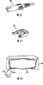
Figure 32 is the perspective view by the plug of one embodiment of the invention;
Figure 33 is the perspective view by the clip of one embodiment of the invention;
Figure 34 demonstrates the plug and the clip of connection status, and the effect that comprises is tried hard to;
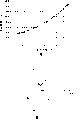
Figure 35 is the graph of relation of flexibility and rigidity and glass content;
Figure 36 is that the effect of the power that runs into of plug is tried hard to;
Figure 37 is the active force main body figure of power shown in Figure 36;
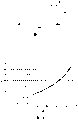
Figure 38 is the graph of relation at pulling force and inclination angle.
Embodiment
The preferred embodiments of the present invention are described now.In one form, comprise 3 elements by equipment of the present invention: (i) socket, (ii) plug and (iii) geometrical clamp.Each element in these elements is described now.
Be suitable for supplying with the lead of total electric energy to Medical Devices by the socket of the embodiment of the invention, socket constitutes the part of detachable insertable chuck 70, as shown in Figure 7.Chuck 70 inserts or otherwise is fixed in the hole in the shell of Medical Devices (not shown).When chuck 70 inserted in the shells, the surface 71 of chuck 70 usually and the flush of shell.The jack 74 of a pair of being generally " D " shape extends to the chuck 70 from jaw face.By this routine standard testing, the degree of depth of jack 74 roughly is 16mm.The diameter of each D shape jack 74 roughly is 9mm.Should be to the configuration side by side mutually of its back side of " D " shape jack.The center of each jack is to be roughly columniform straddle or to sell 76, and pin 76 length that extend in the jack 74 roughly are 9mm.Pin 76 provides with plug and electrically contacts when plug inserts.By another form of the present invention, socket comprises single trapezoidal jack rather than that a pair of " D " shape jack shown in Fig. 7 (a) of being roughly.On the limit of jack 74 and on the surface 71 of chuck 70 a pair of lug 72 is being set, each lug has the cylindrical hole 78 that passes it.Lug 72 is used to allow the pivotal engagement with geometrical clamp.The diameter in hole 78 roughly is 4.5mm.Hole 78 also comprises a breach or recess 78a, will be referring to Figure 10 (b) explanation below the function of recess 78a.By the preferred embodiments of the present invention, lug 72 roughly is " D " shape, also can use other shape as rectangle, and its condition is that they have enough intensity supporting geometrical clamps 90 (seeing that Fig. 9 (a) is to 9 (d)).For clear, should be realized that the chuck among Fig. 7 has a pair of " D " shape jack 74 and a pair ofly comprises that two roughly is the jack 74 of square indentations 75.
For clear, should be realized that Fig. 7 (a) has a pair of " D " shape jack 74 and a pair ofly comprises that two roughly is the jack of square indentations 75 to the chuck of Fig. 7 (c).
By another embodiment of the present invention, a pair of jack 74 comprises that two roughly is square indentations, and each square indentations has the rounding that is used for polarization.Has thin partition wall between two grooves.
Fig. 8 (a), 8 (b), 8 (c) and 8 (d) are end-view, plane graph and the perspective views that shows respectively by the plug 80 of the embodiment of the invention.Plug 80 comprises that a pair of lug 82 and a pair of straddle receive jack or pin joint is received the pin 76 that slit 84 is used to receive chuck 70.The end 86 of plug 80 is used for inserting slidably the jack 74 of socket of chuck 70 by this mode, the partial-length of plug 80 is received in the chuck 70, but lug 82 is still stayed the outside of jack 74, so that the inclined surface 95 of geometrical clamp can mesh with geometrical clamp 90.In another kind of form of the present invention, it roughly is trapezoidal groove that chuck 70 has single, and to replace a pair of jack 74, plug 80 has corresponding shape, is roughly in the trapezoidal jack so that can insert.In the another kind of form of the present invention, on plug 80, has only a lug 82.
Fig. 9 (a), 9 (b), 9 (c) and 9 (d) are end-view, plane graph and the perspective views that shows respectively by the geometrical clamp 90 of the embodiment of the invention.Geometrical clamp 90 comprise a pair of straddle or sell 92 and pair of joint sheet or 94, one protuberances 94 of protuberance be positioned at each end of a pair of cantilever 96.One or two straddle comprises cam or protrusion, will be referring to Figure 10 (b) explanation below the function of cam or protrusion.Cantilever 96 can be by the arrow indicated direction elastic bending on Fig. 9 (b), and is connecting with bridge 99 with this end to the relative extension position of pin 92.In the hole 78 of the lug 72 of pin 92 insertion chucks 70, arrive shown in Figure 12 as Figure 10 (a).Insert like this in case sell 92, geometrical clamp 90 just can be sold 92 rotations relatively, shown in Figure 10 (b).In one form, when inserting in the chuck 70, plug 80 do not have only geometrical clamp 90 can insert in the chuck 70.Figure 10 (b) demonstrates the horizontal level of geometrical clamp 90, and still, in case geometrical clamp 90 is rotated into Figure 11 and upright position shown in Figure 12, protuberance 94 just can mesh with the lug 82 of plug 80.Geometrical clamp 90 is included in the groove 98 in its bridge 99, can receive the top 88 or the leads of plug 80 in the groove 98.Geometrical clamp 90 comprises pair of angled surface 95.
Figure 10 (a) and 10 (b) demonstrate the assembly of socket 70, plug 80 and geometrical clamp 90 in non-locked position.Geometrical clamp 90 was placed in the lug 72 of chuck 70 in place before plug 80 inserts slidably.For with plug 80 locks in place, geometrical clamp 90 must revolve from the position shown in Figure 10 (b) and turn 90 degrees Figure 11 and position shown in Figure 12.Geometrical clamp 90 rotation and with the process of plug 80 engagements in, cantilever 96 has slight distortion, thereby protuberance 94 is passed through on the lug 82 of plug 80, in case protuberance 94 passes through on the straddle of lug 82, just can prevent geometrical clamp 90 rotations, and locks in place in this way, remove up to plug.
Shown in Figure 10 (b), above-mentioned recess 78a and cam or protrusion 92a are designed to geometrical clamp 90 to press arrow " C " indicated direction when rotation in alignment.Cam or protrusion 92a are connected (Fig. 7 C) with the inner surface in hole 78, and vertical to produce (last or following) be the frictional force of geometrical clamp fixedly.Be maintained fixed like this and press from both sides not the contact plug connector and make assembling easily.Recess 78a and cam/protrusion 92a can be arranged on other positions and replace illustrated exemplary position, and therefore, in assembling process, geometrical clamp can be fixed on other temporary transient positions.
Plug 80 can be by the direction drawing of Figure 11 and arrow A shown in Figure 12 and is removed from assembly.In the process by this direction dismounting plug 80, the cantilever 96 of geometrical clamp 90 has slight deformation by the arrow B indicated direction, and lug 82 is thrown off.And in the process by arrow A indicated direction dismounting plug 80, lug 82 passes through on each corresponding inclined-plane 95.Depend on multiple factor from assembly dismounting plug 80 required power, these factors comprise: (i) elasticity of cantilever 96, the (ii) friction between lug 82 and the protuberance 94, and the (iii) friction between lug 82 and the inclined-plane 95.Therefore, from assembly, remove needed power in order to regulate plug 80, can be individually or several these factors (i) of regulating a collection ofly, (ii), (iii) each factor in.
In case plug is connected to socket and geometrical clamp is in place to be fixedly attached to the plug of socket, any mode in then can be is in two ways dismantled plug from socket, and plug is thrown off from socket.By first kind of mode, the plug dismounting is carried out in two steps, and by continuous mode, geometrical clamp is at first thrown off from plug, then from socket dismounting plug.By the second way, throw off geometrical clamp and dismantle plug from socket to small part simultaneously.
From first kind of mode of socket dismounting plug is not have unconscious or do not note the mode that adopts usually under the situation of added removal force at plug or its connection electric wire or equipment.This mode can be carried out in two steps.The geometrical clamp opposite mode of mode in place when being connected to socket by plug, at first geometrical clamp unclamps from plug.As the part of this process, add enough power on the geometrical clamp, so along with contact chip 96 on lug 82 by causing cantilever 96 distortion.Geometrical clamp 90 is contact plug not, and in other words, geometrical clamp 90 rotates to position shown in Figure 10 from Figure 11 and position shown in Figure 12.In case the geometrical clamp of rotation is thrown off from plug, dismantle plug from socket by the general mode that is fit to the plug and socket combination.In this stage, the required power of dismounting plug should be less than the release force of plug and geometrical clamp assembling.
From the second way of socket dismounting plug is to be subjected to the mode that adopts usually under the situation of unconscious or careless removal force at plug or its connection electric wire or equipment.In the second way, when deviating from, geometrical clamp occurs simultaneously from socket dismounting at least a portion plug.This mode is only with a step.
Influence the series of factors of when utilizing geometrical clamp, dismantling the required power of plug owing to can regulate, therefore can control required power and realize above-mentioned (two steps) continuously and while (one goes on foot) dismounting mode from socket.By putting into practice the present invention, dismantle the high release force threshold value that plug is used to reach by a step mode, that is, make the plug and socket combination of connection can resist its value up to the unconscious of 100 to 300 newton or do not note added removal force, go on foot when dismantling the permission geometrical clamp and throw off easily carrying out two simultaneously.In the present embodiment, thus will apply the power with the combination approximate vertical of plug and socket makes geometrical clamp throw off from plug for this reason.Usually the power value that is approximately perpendicular to the plug and socket combination should be the power that any typical user adds easily with a hand.
The method that is identified for the suitable release force of plug, socket and geometrical clamp combination will be considered outside decisive factor, for example, the standard that can use, the standard of breathing apparatus for example, it requires connector can continue to bear 300 newton's power one minute.Determine factor in case satisfied whole outsides of minimum removal force, just can determine actual release force problem then.
A kind of mode is, considers and will determine release force with other aspects of the equipment of geometrical clamp.For example, equipment moves desired power by the direction of pull of carrying by lead, can be as the factor of determining.Under typicalness, more satisfactory is that maximum release force value is arranged on the level that geometrical clamp can be unclamped, rather than adds enough power to equipment and come mobile device.This configuration is used to prevent owing to there being pulling force to be sent to this equipment equipment is highly moved than level from one.Advantage of the present invention is, freely rest on the transport vehicle or the equipment on other stands can not be pulled on the transport vehicle or the edge of stand, cause and pound the people and pound danger on the floor, because be transported to equipment at enough pulling force, make equipment move on the transport vehicle or the edge of stand before, geometrical clamp can unclamp and make plug and throw off with device portal owing to dismantle, equally, can adopt this configuration, to prevent equipment and other critical systems being thrown off as the result who moves in the direction that causes disengagement by other means.For example, by the present invention, breathing apparatus can constitute: the pulling force that applies by the general supply line can cause that general supply plug geometrical clamp unclamps and makes the general supply plug throw off by the predetermined active force slave unit of the present invention, simultaneously, breathing apparatus still is connected to for example accessory power supply of reserve battery power supply.Equally, if breathing apparatus moves in the direction of leaving general supply, under the situation of the power of unclamping less than the power of unclamping in the connection that is applied between stand-by power supply and the breathing apparatus that the general supply line is used, the present invention will allow the stand-by power supply plug to throw off general supply plug disengagement before.In such a way, can be by also determining release force with reference to the equipment surface that will move with reference to moving the required power of connected equipment.The weight of the equipment that can be subjected to and the influence of the plane moving resistance that causes along the equipment point that contacts with the apparent surface are moved in flat surface.Therefore when determining removal force, should consider the equipment point and the apparent surface of contact material.These surfaces can constitute with identical or different materials, the rubber earring moulding of constitution equipment pedestal for example, and identical or different processing can be carried out with the apparent surface in these surfaces.These surfaces can be smooth, the irregular surface texture that also can influential equipment moves.For example, equipment has normally used pedestal, adds pulling force by lead on this pedestal contact surface and moves.Pedestal can constitute a workpiece, it as equipment around the surface, for example, pedestal can be the projection that is stamped in the equipment metal shell, perhaps by the plastic casing mold pressing of equipment.Perhaps, pedestal can be fixed on the device housings, perhaps is fixed on the equipment component that passes the hole in the shell.The fixture of pedestal can be used for also can being not used in the permanent plant shell, and its inner member is in place relatively.Then, equipment base can contact flat apparent surface, or with opposite face in meshing point engagement, opposite face for example is the groove that constitutes the receiving equipment pedestal.Perhaps, the apparent surface can have the bulge of rising, so that mesh with equipment base or device housings.Equally, equipment can be fluted, to receive apparent surface's fixed projection thing.This structure will influence by the required power of the relative apparent surface's mobile device of any desired direction.
Also can constitute plug by the combination of geometrical clamp of the present invention and plug and in horizontal plane, surround geometrical clamp, move by angle form, rather than geometrical clamp move to vertical plane from horizontal plane in the above embodiments around the plane.
In a kind of preferred form, socket constitutes with the glass of having filled nylon 66, and geometrical clamp constitutes with nylon, and plug uses the PVC of molding on lead and terminal assembly.
In another form, the present invention also is included on the geometrical clamp the suitably tab of location, and by unintentionally or the release force that adds of accidental mode and unclamp geometrical clamp, tab can be out of shape, and can with the naked eye find out event with response.This is in that to point out that formally such incident takes place more useful.By making this irreversible mode of tab distortion, although plug can insert socket again and geometrical clamp comes into force again,, naked eyes still can be seen unintentionally or accidental plug dismounting.
Figure 13 (a) demonstrates another kind of form of the present invention to Figure 18, and is different to form shown in Figure 12 with Fig. 7.Identical reference number is indicated similar feature.
At thickness is that 40mm * 27mm, radius of corner are that jack assemblies is packed in the Medical Devices in the shell aperture in the metal plate of 1.6mm for the 2.5mm test size.Socket can bear 330 newton's pullout forces.Assembly comprises: double pole single throw switch, total connector of IEC320 and ad hoc DC socket.With geometrical clamp general supply and DC plug are fixed in the socket.When 100 newton's release force was added on the lead, geometrical clamp unclamped from plug, and plug is thrown off from socket.Plug, socket and switch module are deferred to the IEC320 standard.
Can make socket with nylon 66 and reinforcing glass.4 run buttons and 4 clamping rings can bear release force, and said 4 is for example.In order to guarantee to assemble, can regulate the length of 4 buttons.The configuration design of DC plug and socket becomes to make the IEC320 plug can not be installed into DC socket, and DC connects polarity.In use can not be near the DC contact, or by the standard testing finger near the DC contact, because the DC contact is recessed dearly.
Press IEC320 molding plug: the molding plug of pressing IEC320 is the same with standard IEC 320 plugs, just also has additional clamping lug.These lugs have two purposes.In conjunction with the distinguishing mark and the number of spare parts that raise, they help to clamp plug so that the removal of the insertion of plug and plug.They also are used for engagement and starting plug fixed device.
The specific DC plug of molding (seeing Figure 19 and 20): the shape of the specific DC plug of molding is according to standard IEC 320, and just it has different profiles, and it is than length and additional clamping lug is arranged.The power supply that this plug requires is the 30V DC of 2.5A, and for the insertion quantity by standard code, connection is reliably, and contact resistance is no more than 10m Ω.Plug has the color of regulation.Plug also have distinguishing mark and shown in number of spare parts.
Plug geometrical clamp (seeing Figure 21 to 31): have two geometrical clamps to be used for fixing AC plug and DC plug.They constitute with the nylon of for example nylon 66.For the plug removal force that changes requirement can be regulated oblique angle 100 (seeing Figure 27) and retention tab 101 (seeing Figure 28 and 31).Can regulate the thickness of geometrical clamp.
Exit at the socket back side: in this example, exit and lead at the socket back side are installed in the flow generator of being made by ResMed company " S6 " and " S7 ".
Embodiments of the invention have been described with reference to constituting power line, connector and the device intake of propagating electromagnetic energy.But the present invention can also be used for the function of estimating of other system.
For example, other system relates to other broadcasting systems with optical fiber and terminal.
In addition, the present invention also is applicable to the Medical Devices of ventilation.
In medical ventilator field (that is, breathing apparatus), gas delivery system can be used to connect source of suction to patient interface, perhaps, connects sensor port to transducer, with detected pressures or other system parameter.
Be suitable for carrying in the positive airway pressure breathing apparatus of Noninvasive, perhaps, in the breathing apparatus of the continuous positive pressure therapy of nasal cavity, essential element is a flow generator, and it has outlet and the gas conduit of supplying with breathable gas, in gas conduit, the gas that can suck moves to patient's interface from flow generator, for example, be connected to the face shield of gas conduit, the gas delivery that can suck is to the user.In suction device, also comprise other elements of breathing circuit, for example, humidifier or I-shaped filter.Humidifier is used in the breathing apparatus, to the breathable gas humidifier that will supply with the user.Usually humidifier is placed in the breathing circuit between the breathable gas source and patient interface.The example of I-shaped humidifier is disclosed among american documentation literature US-A-6338473 and the U.S. appearance design US-419658.PCT patent application PCT/AU02/00155 and PCT/AU02/00156 disclose the example of I-shaped humidifier and an integral body of flow generator formation.Humidifier also can be placed between flow generator and the patient interface, and is for example disclosed among the U.S. Patent application document No.09/099665.The full content of every citing document is incorporated by reference in this application.
Common main element module whole in breathing circuit, for example flow generator, I-shaped filter, humidifier, patient interface also are connected with each element fluid ground of the gas conduit that is connected to different length with the gas conduit of different length by means of the rubber friction mounting bush.
Advantage with breathing circuit of the present invention is, if breathing circuit bears release force, then fixture is unclamped, and the part in permission loop is subjected to the effect of release force, throws off from the remainder of breathing circuit at the regulation point.Regulation point be specified to usually with suitable connector and geometrical clamp with it between interconnective two elements.The present invention allows breathing circuit to constitute to make the damage minimum of the element (for example, flow generator, humidifier or patient interface) of system.And the present invention can reduce user or chance that other people come to harm.For example, be added to and cause gas conduit to throw off from humidifier on the gas conduit if surpass the pulling force of release force, then pulling force can not cause the operating position that humidifier breaks away from, thereby can not cause dropping to the user by humidifier and damage and damage on one's body with on the floor.Equally, can prevent that flow generator breaks away from its operating position and causes injury and damage.By preventing that surrender is added on the patient interface pulling force fully under the release force because of geometrical clamp is exposed to, the present invention prevents that the user from feeling under the weather because wearing patient interface, or prevents that the patient interface and the fixed band of direction of pull tension from damaging the user.Equally, breathing apparatus can prevent to respond pulling force and removes before the I-shaped filter and unclamp the pollution that causes because of geometrical clamp.
With advantage of the present invention be, if breathing circuit is subjected to the effect that its size is the pulling force of release force size at least, fixture can be surrendered and be allowed a part of loop in loop to bear release force, throws off at the remainder in desired locations and loop.The position of drop-outs the element that is subjected to tension be connected with fixture between the next element in downstream, pulling force source.
With the release force system of different brackets, the loop constitutes permission " exquisite system throws off ".The meaning that exquisite system throws off is that the may command of finger element is separated.For example, when pulling force is added on the loop, the connection that is designed to unclamp under the lowest pull effect will be the connection of at first yielding to pulling force, and an element in the most close pulling force source or a plurality of element (that is, these elements are positioned at the upstream of relevant disengaging gear) are thrown off with remaining element.By this mode, remaining element is thrown off by destructive pulling force.
Can divide by importance information by interconnective breathing circuit element, the particular interest of pressing the integral body of system adopts the release force of different stage to connect.For example, from humidifier with advantage that the release force characteristic safety point of view that is connected between the gas conduit of patient interface interconnection is seen be, release force is less than the release force that can be added in this connection, the gas conduit inlet that this connection will connect humidifier is connected to the I-shaped filter, and less than the required power of mobile flow generator.Operate this structure, if pulling force is added on the gas conduit, gas conduit interconnection humidifier is to patient interface, and the connection between gas conduit and the humidifier can be yielded to pulling force, prevents that thus humidifier from pulling to the user.The required power of mobile humidifier is more preferably greater than release force, further to reduce the chance that humidifier moves.The size of the power that mobile humidifier is required determined by the fixture that adopts, and for example, humidifier is fixed to the geometrical clamp that its precalculated position is used, and perhaps, base or rubber base plate, base make humidifier and are provided with between the susceptor surface of humidifier and cause friction grip.
And, if the loop comprises the I-shaped filter, polluted by user's entrance point of breathing circuit so that can prevent flow generator, the position of preferred displacement that then makes the connection with minimum release force is in the position than the more close user interface in position of the one or more connections that connect the gas passage between I-shaped filter and the flow generator.By the operation back-off assembly, if relevant connection is subjected to the domination of pulling force size, this pulling force size has the size of relevant release force at least, and then the contamination prevention system of system still is not contaminated.
When determining the maximum release force of the one or more connections between flow generator and the I-shaped filter, the size that maximum release force can be set is equal to or greater than the locomotivity of flow generator.The result who does like this is to determine the preferred sequence of pulling force.The pulling force that connection before moving about flow generator between I-shaped filter and the flow generator is subjected to preferably should take in from the globality of system, and vice versa.Adopt the present invention can obtain any structure.
Other features of the present invention be geometrical clamp and plug to colour coding can be arranged, color is represented geometrical clamp and the right characteristic of plug.For example characteristic is the release force with prescribed level.With with the plug of corresponding geometrical clamp coupling the time, the feature of the predetermined release force of requirement makes up exactly.
Except colour coding, geometrical clamp and plug can be introduced other guiding moulding of for example joint tongue and groove, to allow geometrical clamp and plug to accurate coupling, prevent that right not the matching of geometrical clamp and plug is connected.Use geometrical clamp and plug to being used in the multi-tap system like this, prevent unintentional not matching between the plug and socket.For example, use two plugs, make their straddle and each socket almost close with same structure.With painted geometrical clamp and the plug of same color provide the naked eyes observable plug and socket relevant correctly to match indication with geometrical clamp.Second socket can be connected to the geometrical clamp with different colours, is connected to the socket of disengagement with the indicating predetermined plug with same color of color.
The position of the target cross of geometrical clamp and plug combination is used for the correct assembling of naked eyes directing member.
According to above-mentioned content, the inventor effectively develops and a kind ofly can correctly estimate the pattern of the required power of mobile plug system by it.In this example, " power " is meant from the socket necessary removal force that pulls the plug out of the socket, and/or makes geometrical clamp and plug throw off required release force.Generally, release force is designed to greater than removal force.Therefore, in one embodiment, the pattern of estimating is at release force rather than at the definite pattern of removal force.But the pattern of estimating also can only be used to estimate removal force, for example, and without clip or under only guaranteeing that release force will the situation greater than removal force.
Plant saying by other, the inventor can design plug system by the various parameters of controlling above definition, and whether the plug system of forecasting institute design can satisfy the critical field that discharges removal force, and 100 to 300 newton for example are to be applicable to any predetermined use.
When reaching the release force of regulation, the inventor provides several consideration conditions at design plug geometrical clamp.For example design plug 80 shown in Figure 32 and 33 and geometrical clamp 90, design condition comprises: the width of tab, the rigidity of material and inclination angle.Preference pattern described below is that basis provides the analysis answer to elasticity/plastic analysis, and forming method is not limited to this method.For example, pattern can be used finite element analysis (FEA) formulism.
The tab width is reasonable to be, plug 80 is wanted to sting tightly the tab of (overbite) by a pair of mistake and fixed with geometrical clamp on any one side of cantilever.See Figure 34, in order to discharge straddle, the cantilever at geometrical clamp two ends must have deflection, and departure is " D ", and therefore, the power that is subjected at the contact position plug is Ftab.Simple cantilever beam deviation chart is shown as:
D=Fxtab*L^3/3*E*I
Wherein, D=unclamps the required deviation of plug
The power that Fxtab=skew cantilever beam needs
The length of L=cantilever
The Young's modulus of E=material and
The I=the moment of inertia
Suppose that D, L and E keep constant basis, the moment of inertia I increases, and the power Fxtab that then unclamping plug needs increases.In this case, the tab width increases, and then the moment of inertia I increases, so power Fxtab increases.
For rectangle part,
I=width * height ^3/12
In other words, the width increase can cause unclamping the required line of force increase of plug.
Material stiffness.The rigidity of material depends on glass content.From Charles A.Harper, " the modern plastics handbook " of appendix C .20 can be found the different glass fibre amount in the nylon 66 that adds.
Table 1
| X-axle-glass content (%) |
Y-axle-bending strength (psi) |
| 15 |
480 |
| (31.5 on average) |
800 |
| 50 |
1460 |
Sample is in the poised state of 50% relative humidity
Figure 35 demonstrates the relation curve between content of glass fiber and the bending stiffness.This curve is exponential extrapolation curve, is used to estimate the characteristic when less glass content.
The inclination angle.It is how hard that tilt quantity will determine that the plug that will spur has, to obtain unclamping the required enough vertical forces of geometrical clamp from lug.See Figure 36, N=is in the geometrical clamp at selected inclination angle and the contact force between the plug, and the Fytab=plug is by the suffered power of geometrical clamp tab (supposing approximately vertical), and Fpull=draws back the required power of plug from wire clamp.
Suppose that these power synthesize free body figure shown in Figure 37, the regulation all summation of these power equals 0, Fytab/Fpull=TanX, wherein, X=angle (degree), then
Fpull=Fytab/Tan X...........(B)
Wherein, Fytab is constant (the equal no change of tab or material)
In order to test the precision of release force preassigned pattern, select minimum release force Fpull 〉=100N.First trial is the release force value of regulation approximate desired.With the following train value of the following parameters described relation curve of equation (B) that draws, therefore, be provided at the possible force value scope in different inclinations angle to us.
Parameter
Tab width=the 1.7mm of contact position
The X=45 degree, the nylon 66 of the glass of material=add 10%
The result who obtains: Fpull=31.7N (newton, mean value)
Figure 38 obtains above value substitution equation (B).Find out that from this result the release force of estimating is too little.According to this pattern, need to change the one or more parameters in 3 canonical parameters, so that the minimum release force of plug system is 100N at least.
Second trial be, the inclination angle becomes 60 degree from 45 degree, that is, X=60 degree (rising to 60 degree) from 45 degree, this be worth substitution equation (B), the release force that acquisition is estimated.As can be seen from Figure 38, if the tab width is identical identical with glass content, this discreet value should be~54N.Certainly, this power is too little, so other parameters will change, that is: tab width=2.2mm (increasing from 1.7mm)-length increases by 29.5%; Glass content=15% (increasing from 10%)-this is to increase to 480psi from 400, has increased by 20%.Consider that all these change the release force=54*1.295*1.2=83.9N that estimates.The jack terminals pulling force increases 45.35N, and the release force that we estimate is 129.25N.
It is 143.75N that the pulling-off force of the reality that obtains adds with the power that is caused by jack terminals together.Therefore, compare with the 129.25N that estimates, difference is 14.5N, or 11%.The deviation that may cause:, make the more difficult skew of cantilever along with the tab width increases the rigidity that in fact plug runs into bigger geometrical clamp cantilever.Its reason is, the tab width partly increases towards the harder shape of geometrical clamp, and this makes us that more complicated skew cantilever mechanism rather than simple cantilever beam skew will be arranged.But, by simple change cantilever beam modes of deflection, so that adopt more comprehensively pattern in the back.
Although shown and described the most useful preferred embodiment,, the spirit and scope of the present invention are not limited to the detailed description here.