CN100364875C - Frameless drive for elevator - Google Patents
Frameless drive for elevator Download PDFInfo
- Publication number
- CN100364875C CN100364875C CNB2004100923802A CN200410092380A CN100364875C CN 100364875 C CN100364875 C CN 100364875C CN B2004100923802 A CNB2004100923802 A CN B2004100923802A CN 200410092380 A CN200410092380 A CN 200410092380A CN 100364875 C CN100364875 C CN 100364875C
- Authority
- CN
- China
- Prior art keywords
- motor
- end plate
- drg
- plate
- supported
- Prior art date
- Legal status (The legal status is an assumption and is not a legal conclusion. Google has not performed a legal analysis and makes no representation as to the accuracy of the status listed.)
- Active
Links
- 230000006835 compression Effects 0.000 claims description 7
- 238000007906 compression Methods 0.000 claims description 7
- 230000000694 effects Effects 0.000 claims description 7
- 230000008030 elimination Effects 0.000 claims 1
- 238000003379 elimination reaction Methods 0.000 claims 1
- 238000010276 construction Methods 0.000 description 1
- 238000005516 engineering process Methods 0.000 description 1
- 238000004519 manufacturing process Methods 0.000 description 1
- 230000000246 remedial effect Effects 0.000 description 1
- 238000000926 separation method Methods 0.000 description 1
- 238000009966 trimming Methods 0.000 description 1
Images


Classifications
-
- B—PERFORMING OPERATIONS; TRANSPORTING
- B66—HOISTING; LIFTING; HAULING
- B66B—ELEVATORS; ESCALATORS OR MOVING WALKWAYS
- B66B11/00—Main component parts of lifts in, or associated with, buildings or other structures
- B66B11/04—Driving gear ; Details thereof, e.g. seals
-
- B—PERFORMING OPERATIONS; TRANSPORTING
- B66—HOISTING; LIFTING; HAULING
- B66B—ELEVATORS; ESCALATORS OR MOVING WALKWAYS
- B66B11/00—Main component parts of lifts in, or associated with, buildings or other structures
- B66B11/04—Driving gear ; Details thereof, e.g. seals
- B66B11/043—Driving gear ; Details thereof, e.g. seals actuated by rotating motor; Details, e.g. ventilation
Abstract
A drive unit has at least one motor, a motor stand, a bearing block, a drive pulley and a counter-roller attachment. The drive pulley is mounted at the motor stand and at the bearing block by a shaft. A respective brake is arranged at the bearing block at each side. Webs connect the motor stand with the bearing block. The motor stand, the bearing block and the webs form a stable structure without an engine frame carrying the motor stand and the bearing block being necessary. A counter-roller attachment consisting of side plates and a counter-roller is arranged directly at the motor stand and the bearing block.
Description
Technical field
The present invention relates to a kind of Frameless drive of elevator, be made of at least one motor, at least one drg and a driving wheel that is arranged between the end plate, wherein motor is arranged on the end plate.
Background technology
In EP03002866.6, disclosed a kind of driver element, mainly constituted by a motor, a motor cabinet, a bearing seat, a driving wheel and a frame that has beam pulley auxiliary mechanism.The stator of motor utilizes flange to be screwed on the motor cabinet.Rotor be fixed on one to driving wheel support the axle free end on, described axle mounting is on bearing seat and motor cabinet.Driving wheel utilization axle is arranged on motor cabinet and the bearing seat.Drg is arranged in the motor cabinet in-to-in scope and by casing and covers.
The shortcoming of this known devices is that drg is arranged on inside.When safeguarding, be difficult to touch brake components.Another shortcoming is the frame that bearing seat and motor cabinet support is made complex structure and makes whole driver element costliness.
Summary of the invention
At this a kind of remedial measures is proposed.A kind of lift drive unit of no frame is proposed according to the present invention, constitute by at least one motor, at least one drg and a driving wheel that is arranged between the end plate, wherein said lift drive unit under any circumstance can be worked reliably and be simple in structure, has wherein overcome the shortcoming of existing device.
The technical scheme that realizes the object of the invention is:
A kind of lift drive unit of no frame is made of at least one motor, at least one drg and a driving wheel that is arranged between the end plate, wherein motor be arranged on the end plate and each end plate by the seat supports below the corresponding end plate.
Advantage of the present invention mainly is, the scantling length that can realize having the driver element of minor axis and realize the weak point of driver element thereupon.Its another advantage is that brake compression air cylinder and chargine line and brake disc separation are provided with.Brake surface can be by oil pollution under the situation of blowing-by or pipe breakage.Thereby can continue to guarantee braking potential.Another advantage is to adopt the driver element design of no frame can realize the bigger degree of freedom that cable leads between driving wheel and beam pulley.Thereby can realize bigger cable hold every.For example have system height and the total weight more than ten tons more than two meters at big lift car and big delivery head and high running velocity design-calculated driver element, but wherein adopt the design saving in weight and the manufacturing cost of no frame.
Description of drawings
To contrast accompanying drawing is below explained the present invention.Shown in the figure:
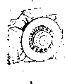
Fig. 1 and Fig. 1 a illustrate the driver element with motor of the present invention;
Fig. 2 illustrates the motor cabinet with driving wheel and connecting panel;
Fig. 3 illustrate have axle sleeve and driving wheel bearing seat;
Fig. 4 illustrates top connecting panel;
Fig. 5 illustrates side connecting plate;
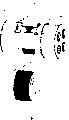
Fig. 6 and Fig. 7 illustrate drg details and
Fig. 8 illustrates the driver element with two motors of the present invention.
The specific embodiment
Fig. 1 illustrates the driver element 1 that finishes of assembling, mainly plays the motor cabinet 3 of end plate effect, bearing seat that plays the end plate effect 4, a driving wheel 5 and a beam pulley auxiliary mechanism 6 by a motor 2A, one and constitutes.The stator 2.1 of motor 2A is arranged on the motor cabinet 3.The rotor 2.2 of motor 2A is supported on the free end of the axle 15 that driving wheel 5 is supported, and described axle is arranged on bearing seat 4 and the motor cabinet 3.The axle free end protrudes in motor cabinet 3.Driving wheel 5 utilizes axle mounting on motor cabinet 3 and bearing seat 4.Drg 7 is arranged on each side of bearing seat 4.
Connecting panel 8,9 links together motor cabinet 3 and bearing seat 4, and connecting panel 8 and each side of wherein for example being provided with above one are respectively arranged with a side connecting plate 9.Motor cabinet 3, bearing seat 4 and connecting panel 8,9 constitute a strong design, thereby no longer need frame that motor cabinet 3 and bearing seat 4 are supported.Motor cabinet 3 and bearing seat 4 utilize strut member 10 no frame ground to be supported on respectively on the carriage 3.1 or carriage 4.1 on corresponding bearing 11 or the support.Beam pulley auxiliary mechanism 6 is made of side plate 12 and beam pulley 13, is set directly on motor stator 3 and the bearing seat 4.A hydraulic pressure unit 14 is used for the actuator of drg is presented.Also can carry out electrical control to actuator.
Fig. 2 illustrate have driving wheel 5, the motor cabinet 3 of side connecting plate 9 and top connecting panel 8.Bearing seat 4 shown in Figure 3.Axle 15 the end that driving wheel 5 is supported is installed on the motor cabinet 3 and its other end is installed on the bearing seat 4.With 16 bearings that indicate on the bearing seat side.Driving wheel 5 is provided with a brake disc 17 with ring gear 18, drives by 5 pairs of driving wheels 5 of described ring gear when the emergency evacuation operation.
Fig. 3 is the interior views with bearing seat 4 of axle sleeve 19, and described bearing seat is used to hold bearing 16.Can see circle ring 20 in addition in the drawings, described circle ring is provided with drg 7.The areal of support of the connecting panel 8 above indicating with 21 and with the areal of support of 22 sign side connecting plates 9, wherein connecting panel 8,9 for example can adopt bolt and bearing seat 4 and be connected with motor cabinet 3.
The evacuation drive device is made of the motor 23 with miniature gears 24, and wherein miniature gears 24 meshes with ring gear 18 and driving wheel 5 is moved when evacuating operation.
Fig. 4 illustrates top connecting panel 8, and described top connecting panel is that box type construction and areal of support 8.1 coincide with areal of support 21.
Fig. 5 illustrates side connecting plate 9, and described connecting panel is that wedge structure and areal of support 9.1 coincide with areal of support 22.
Fig. 6 and 7 illustrates the drg 7 that is arranged on driver element 1 each side shaft holder 4, wherein brakes saddle 30 and is installed on the axle 31 that passes circle ring 20 with suspending.Braking saddle 30 maximums can move one utilize trimming screw 32 calibrations apart from d, wherein each axle 31 has a spring 33, described spring loads to driving wheel 5 directions braking saddle 30.The axle 31 be arranged on one with bearing seat 4 bonded assembly angle tables 34 on.The in-to-in brake shoe 40 of braking saddle 30 pairs of driving wheel sides supports and plays a part interval pipe fitting 35 and thread rod 36 are supported, and 36 pairs of the described thread rods for example stay bearing plate 37 of a hydraulic actuator 38 are fixed.One end of compression spring 39 is supported on the stay bearing plate 37 and the other end is supported on the pressure plate 41, and the spigot 42 that described pressure plate utilization is braked saddle 30 guiding passes to exterior brake shoe 43 with the spring force of compression spring 39.For realizing the release to drg 7, the actuator 38 that is activated utilizes pull bar 44 to act on the pressure plate 41 and removes the spring force that acts on outside brake shoe 43 with the compression spring 39 of pull bar 44 coaxial settings.Wherein brake saddle 30 and moving on driving wheel 5 directions under the effect of the spring force of spring 33, wherein in-to-in brake shoe 40 deviates from driving wheel 17 and moves.The state that is provided with 45 pairs of drgs of a sensor monitors.
Fig. 8 illustrates the driver element with two motors 1 that finishes of assembling, mainly is made of a motor 2A and motor 2B, motor cabinet that plays the end plate effect 3, bearing seat that plays the end plate effect 4, a driving wheel 5 and a beam pulley auxiliary mechanism 6.The axle that is arranged on the end plate 3,4 that driving wheel 5 is supported 15 has two free ends, the rotor of one of them motor 2A wherein is set on a free end and the rotor of another motor 2B is set on another free end.
Connecting panel 8,9 links together motor cabinet 3 and bearing seat 4, wherein for example is provided with the connecting panel 8 above and is provided with a side connecting plate 9 in each side.Motor cabinet 3, bearing seat 4 and connecting panel 8,9 constitute strong designs, thereby the frame that motor cabinet 3 and bearing seat 4 are supported needn't be set.
Claims (7)
1. the lift drive unit of a no frame (1), be made of at least one motor (2A, 2B), at least one drg (7) and a driving wheel (5) that is arranged between the end plate, wherein motor (2A, 2B) is arranged on the end plate and each end plate is supported by the bearing (11) below the corresponding end plate respectively.
2. according to the described driver element of claim 1, it is characterized in that end plate is connected plate (8,9) and links together.
3. according to claim 1 or 2 described driver elements, it is characterized in that, driving wheel (5) is supported by axle (15), described axle is arranged on the motor cabinet (3) that plays the end plate effect and the bearing seat (4) that plays the end plate effect, wherein motor (2A, 2B) be arranged on motor cabinet (3) or the bearing seat (4) and the rotor supports of motor (2A, 2B) on the free end of axle (15).
4. according to the described driver element of claim 3, it is characterized in that end plate is provided with a beam pulley auxiliary mechanism (6), described beam pulley auxiliary mechanism can realize that different rope ropes at interval.
5. according to the described driver element of claim 3, it is characterized in that driving wheel (5) is provided with a brake disc (17) with ring gear (18), when evacuating operation, evacuate the miniature gears (24) and ring gear (18) engagement of motor (23).
6. according to claim 1 or 2 described driver elements, it is characterized in that an end plate is provided with at least one drg (7) at least, described drg utilizes brake shoe (40,43) to act on the brake disc (17).
7. according to the described driver element of claim 6, it is characterized in that, drg (7) has a braking saddle (30) that suspends and be provided with, described braking saddle is fixed brake shoe (40), be supported on the braking saddle with the back plate (37) that actuator (38) is fixed, wherein an end of compression spring (39) is supported on that back plate (37) is gone up and the other end of compression spring (39) is supported on the pressure plate (41), wherein pressure plate (41) the utilization spigot (42) that is braked saddle (30) guiding with the spring force of compression spring (39) pass to another brake shoe (43) and for drg (7) is discharged the actuator (38) that is activated utilize a pull bar (44) act on pressure plate (41) upward and elimination act on the spring force of another brake shoe (43).
Applications Claiming Priority (2)
| Application Number | Priority Date | Filing Date | Title |
|---|---|---|---|
| EP03405807 | 2003-11-13 | ||
| EP03405807.3 | 2003-11-13 |
Publications (2)
| Publication Number | Publication Date |
|---|---|
| CN1616337A CN1616337A (en) | 2005-05-18 |
| CN100364875C true CN100364875C (en) | 2008-01-30 |
Family
ID=34560256
Family Applications (1)
| Application Number | Title | Priority Date | Filing Date |
|---|---|---|---|
| CNB2004100923802A Active CN100364875C (en) | 2003-11-13 | 2004-11-10 | Frameless drive for elevator |
Country Status (7)
| Country | Link |
|---|---|
| US (1) | US7533868B2 (en) |
| EP (1) | EP1531139B1 (en) |
| JP (1) | JP4938973B2 (en) |
| KR (1) | KR101168185B1 (en) |
| CN (1) | CN100364875C (en) |
| CA (1) | CA2487580C (en) |
| HK (1) | HK1077560A1 (en) |
Cited By (1)
| Publication number | Priority date | Publication date | Assignee | Title |
|---|---|---|---|---|
| CN105377741A (en) * | 2013-03-20 | 2016-03-02 | 阿克森Ep股份有限公司 | Drawworks system |
Families Citing this family (8)
| Publication number | Priority date | Publication date | Assignee | Title |
|---|---|---|---|---|
| US7975807B2 (en) * | 2004-01-20 | 2011-07-12 | Franklin Samuel H | Elevator climbing system |
| US7165653B2 (en) * | 2004-11-19 | 2007-01-23 | Magil Corporation | Elevator gearless traction machine construction |
| DE102010034302A1 (en) * | 2010-08-13 | 2012-02-16 | Gustav Magenwirth Gmbh & Co. Kg | Caliper for vehicle, particularly bicycle, comprises fixing device and mounting flange for connecting brake caliper to vehicle, where brake caliper is adjusted parallel to movement direction of brake piston by fixing device |
| JP2015157662A (en) * | 2014-02-24 | 2015-09-03 | 株式会社日立製作所 | hoist |
| US10208817B2 (en) * | 2016-10-10 | 2019-02-19 | Cameron International Corporation | Drawworks gearbox with redundant braking on input side |
| CN112225041A (en) * | 2020-11-04 | 2021-01-15 | 天津市航昊机电设备有限公司 | Pressure release device of control system of cage lifting speed changer |
| CN112320545A (en) * | 2020-11-04 | 2021-02-05 | 天津市航昊机电设备有限公司 | Pressure release device of control system of cage lifting speed changer |
| CN112320546A (en) * | 2020-11-04 | 2021-02-05 | 天津市航昊机电设备有限公司 | Control system of hoisting cage speed changer |
Citations (4)
| Publication number | Priority date | Publication date | Assignee | Title |
|---|---|---|---|---|
| CN1058572A (en) * | 1990-07-26 | 1992-02-12 | 英万蒂奥股份公司 | Gearless drive machine for lifts |
| EP1069068A1 (en) * | 1999-07-16 | 2001-01-17 | Inventio Ag | Compact drive for an elevator |
| EP1156008A1 (en) * | 2000-05-19 | 2001-11-21 | Inventio Ag | Brake arrangement for lift drive |
| US20030155184A1 (en) * | 2002-02-18 | 2003-08-21 | Andrzej Cholinski | Drive unit with brake for an elevator |
Family Cites Families (17)
| Publication number | Priority date | Publication date | Assignee | Title |
|---|---|---|---|---|
| US3559768A (en) * | 1969-12-22 | 1971-02-02 | Henry P Cox | Emergency elevator evacuation of tall buildings |
| FR2398014A1 (en) * | 1977-07-18 | 1979-02-16 | Mitsubishi Electric Corp | EMERGENCY DEVICE FOR THE AUTOMATIC SHUT-OFF OF AN ELEVATOR CABIN ON A FLOOR LEVEL IN THE EVENT OF A POWER FAILURE IN SERVICE |
| JPS54146361A (en) * | 1978-05-10 | 1979-11-15 | Hitachi Ltd | Elevator driving apparatus for use at the time of interruption of power supply |
| JPS6039627B2 (en) * | 1979-12-26 | 1985-09-06 | 株式会社日立製作所 | Elevator control device during power outage |
| JPS5954477A (en) * | 1982-09-20 | 1984-03-29 | Toyo Seikan Kaisha Ltd | Manufacture of can barrel |
| JPS5954477U (en) * | 1982-10-04 | 1984-04-10 | 三菱電機株式会社 | Hoisting machine for elevator |
| ES517396A0 (en) * | 1982-11-15 | 1984-04-01 | Perez Marcelino De La | SAFETY DEVICE FOR THE EVACUATION OF LIFTS IN CASES OF EMERGENCY. |
| FI84051C (en) * | 1988-03-09 | 1991-10-10 | Kone Oy | LINUPPHAENGNING FOER EN HISS. |
| US5101939A (en) * | 1990-04-13 | 1992-04-07 | Otis Elevator Company | Disk brake for elevator |
| EP0745553A1 (en) * | 1995-06-02 | 1996-12-04 | Inventio Ag | Lift driving unit |
| JPH09142761A (en) * | 1995-11-24 | 1997-06-03 | Mitsubishi Electric Corp | Hoisting machine for elevator |
| JP3537348B2 (en) | 1999-04-05 | 2004-06-14 | 三菱電機株式会社 | Traction elevator hoist |
| JP2001294385A (en) * | 2000-04-07 | 2001-10-23 | Mitsubishi Electric Corp | Hoisting machine device for elevator |
| CN1245323C (en) * | 2000-05-19 | 2006-03-15 | 因温特奥股份公司 | Actuator for emergency operation of gearless driving machine of elevator |
| MY130686A (en) * | 2002-02-18 | 2007-07-31 | Inventio Ag | Portable emergency drive for an elevator |
| SG110016A1 (en) * | 2002-02-18 | 2005-04-28 | Inventio Ag | Engine frame with counter-roller support for an elevator drive |
| EP1338550B1 (en) | 2002-02-18 | 2008-04-02 | Inventio Ag | Drive unit with brake for a lift |
-
2004
- 2004-10-29 JP JP2004315239A patent/JP4938973B2/en not_active Expired - Fee Related
- 2004-11-01 US US10/979,440 patent/US7533868B2/en active Active
- 2004-11-04 EP EP04026113.3A patent/EP1531139B1/en active Active
- 2004-11-10 CN CNB2004100923802A patent/CN100364875C/en active Active
- 2004-11-12 CA CA2487580A patent/CA2487580C/en active Active
- 2004-11-12 KR KR1020040092238A patent/KR101168185B1/en active IP Right Grant
-
2005
- 2005-10-25 HK HK05109468.9A patent/HK1077560A1/en unknown
Patent Citations (5)
| Publication number | Priority date | Publication date | Assignee | Title |
|---|---|---|---|---|
| CN1058572A (en) * | 1990-07-26 | 1992-02-12 | 英万蒂奥股份公司 | Gearless drive machine for lifts |
| EP1069068A1 (en) * | 1999-07-16 | 2001-01-17 | Inventio Ag | Compact drive for an elevator |
| EP1156008A1 (en) * | 2000-05-19 | 2001-11-21 | Inventio Ag | Brake arrangement for lift drive |
| US20030155184A1 (en) * | 2002-02-18 | 2003-08-21 | Andrzej Cholinski | Drive unit with brake for an elevator |
| CN1439596A (en) * | 2002-02-18 | 2003-09-03 | 因温特奥股份公司 | Elevator driving unit with brake |
Cited By (1)
| Publication number | Priority date | Publication date | Assignee | Title |
|---|---|---|---|---|
| CN105377741A (en) * | 2013-03-20 | 2016-03-02 | 阿克森Ep股份有限公司 | Drawworks system |
Also Published As
| Publication number | Publication date |
|---|---|
| CA2487580C (en) | 2012-04-03 |
| CA2487580A1 (en) | 2005-05-13 |
| JP2005145717A (en) | 2005-06-09 |
| KR101168185B1 (en) | 2012-07-25 |
| HK1077560A1 (en) | 2006-02-17 |
| CN1616337A (en) | 2005-05-18 |
| US7533868B2 (en) | 2009-05-19 |
| US20050103574A1 (en) | 2005-05-19 |
| EP1531139B1 (en) | 2014-01-15 |
| KR20050046594A (en) | 2005-05-18 |
| EP1531139A1 (en) | 2005-05-18 |
| JP4938973B2 (en) | 2012-05-23 |
Similar Documents
| Publication | Publication Date | Title |
|---|---|---|
| CN108568114A (en) | A kind of hanging type chute | |
| CN100364875C (en) | Frameless drive for elevator | |
| US5769183A (en) | Drive unit for a self-propelled elevator car | |
| CN1436714A (en) | Non-machinery compartment tractive pulley lift system | |
| CN102381615A (en) | Railcar structure for corridor elevator | |
| CN1683040A (en) | Lift tanslation driving system of stage manned frame | |
| CN1785775A (en) | Pulley arrangement for elevators | |
| CN102099280A (en) | Elevator system with automotive elevator cabin | |
| CN1657394A (en) | Counterweight for a vertical elevator | |
| WO2014064752A1 (en) | Elevator pulley device | |
| JP2000219444A (en) | Drive unit for elevator | |
| CN1257097C (en) | Belt-drive elevator dragging machine | |
| CN201077704Y (en) | Express elevator vibration damping rope turn backing device | |
| CN202967895U (en) | Constant-wheel-pressure driving system of hoisting equipment | |
| CN112660191B (en) | Framework of bogie and bogie | |
| CN205998801U (en) | A kind of elevator car top wheel mounting structure | |
| CN1188338C (en) | Elevator driving unit with brake | |
| CN1709779A (en) | Driving device for elevator | |
| CN212738060U (en) | Single track loop wheel machine overspeed protection device | |
| CN202164005U (en) | Rail cart structure for elevator of corridor | |
| JP2011042422A (en) | Car of pushing-up type elevator | |
| CN111845792A (en) | Single track loop wheel machine car overspeed protection device | |
| CN2698758Y (en) | Small machine room elevator | |
| JP5555070B2 (en) | Self-propelled elevator and traveling carriage used for the same | |
| CN2698759Y (en) | Small machine room elevator |
Legal Events
| Date | Code | Title | Description |
|---|---|---|---|
| C06 | Publication | ||
| PB01 | Publication | ||
| C10 | Entry into substantive examination | ||
| SE01 | Entry into force of request for substantive examination | ||
| C14 | Grant of patent or utility model | ||
| GR01 | Patent grant | ||
| TR01 | Transfer of patent right |
Effective date of registration: 20231201 Address after: No. 555 Xingshun Road, Jiading District, Shanghai Patentee after: SCHINDLER (CHINA) ELEVATOR Co.,Ltd. Address before: Swiss Helge Sitwell Patentee before: Inventio AG |
|
| TR01 | Transfer of patent right |