BRPI1005531B1 - INSTALLATION FOR ASSEMBLY OF MECHANICAL PARTS ON MOTOR VEHICLE BODIES - Google Patents
INSTALLATION FOR ASSEMBLY OF MECHANICAL PARTS ON MOTOR VEHICLE BODIES Download PDFInfo
- Publication number
- BRPI1005531B1 BRPI1005531B1 BRPI1005531-2A BRPI1005531A BRPI1005531B1 BR PI1005531 B1 BRPI1005531 B1 BR PI1005531B1 BR PI1005531 A BRPI1005531 A BR PI1005531A BR PI1005531 B1 BRPI1005531 B1 BR PI1005531B1
- Authority
- BR
- Brazil
- Prior art keywords
- section
- pallet
- mechanical parts
- line
- screwing
- Prior art date
Links
Images


Classifications
-
- B—PERFORMING OPERATIONS; TRANSPORTING
- B23—MACHINE TOOLS; METAL-WORKING NOT OTHERWISE PROVIDED FOR
- B23P—METAL-WORKING NOT OTHERWISE PROVIDED FOR; COMBINED OPERATIONS; UNIVERSAL MACHINE TOOLS
- B23P19/00—Machines for simply fitting together or separating metal parts or objects, or metal and non-metal parts, whether or not involving some deformation; Tools or devices therefor so far as not provided for in other classes
- B23P19/04—Machines for simply fitting together or separating metal parts or objects, or metal and non-metal parts, whether or not involving some deformation; Tools or devices therefor so far as not provided for in other classes for assembling or disassembling parts
- B23P19/06—Screw or nut setting or loosening machines
-
- B—PERFORMING OPERATIONS; TRANSPORTING
- B62—LAND VEHICLES FOR TRAVELLING OTHERWISE THAN ON RAILS
- B62D—MOTOR VEHICLES; TRAILERS
- B62D65/00—Designing, manufacturing, e.g. assembling, facilitating disassembly, or structurally modifying motor vehicles or trailers, not otherwise provided for
- B62D65/02—Joining sub-units or components to, or positioning sub-units or components with respect to, body shell or other sub-units or components
- B62D65/12—Joining sub-units or components to, or positioning sub-units or components with respect to, body shell or other sub-units or components the sub-units or components being suspensions, brakes or wheel units
-
- B—PERFORMING OPERATIONS; TRANSPORTING
- B62—LAND VEHICLES FOR TRAVELLING OTHERWISE THAN ON RAILS
- B62D—MOTOR VEHICLES; TRAILERS
- B62D65/00—Designing, manufacturing, e.g. assembling, facilitating disassembly, or structurally modifying motor vehicles or trailers, not otherwise provided for
- B62D65/02—Joining sub-units or components to, or positioning sub-units or components with respect to, body shell or other sub-units or components
- B62D65/18—Transportation, conveyor or haulage systems specially adapted for motor vehicle or trailer assembly lines
-
- B—PERFORMING OPERATIONS; TRANSPORTING
- B23—MACHINE TOOLS; METAL-WORKING NOT OTHERWISE PROVIDED FOR
- B23P—METAL-WORKING NOT OTHERWISE PROVIDED FOR; COMBINED OPERATIONS; UNIVERSAL MACHINE TOOLS
- B23P2700/00—Indexing scheme relating to the articles being treated, e.g. manufactured, repaired, assembled, connected or other operations covered in the subgroups
- B23P2700/50—Other automobile vehicle parts, i.e. manufactured in assembly lines
-
- Y—GENERAL TAGGING OF NEW TECHNOLOGICAL DEVELOPMENTS; GENERAL TAGGING OF CROSS-SECTIONAL TECHNOLOGIES SPANNING OVER SEVERAL SECTIONS OF THE IPC; TECHNICAL SUBJECTS COVERED BY FORMER USPC CROSS-REFERENCE ART COLLECTIONS [XRACs] AND DIGESTS
- Y10—TECHNICAL SUBJECTS COVERED BY FORMER USPC
- Y10T—TECHNICAL SUBJECTS COVERED BY FORMER US CLASSIFICATION
- Y10T29/00—Metal working
- Y10T29/53—Means to assemble or disassemble
- Y10T29/534—Multiple station assembly or disassembly apparatus
- Y10T29/53417—Means to fasten work parts together
Abstract
instalação para montagem de partes mecânicas em corpos de veículos motores uma instalação para montagem de partes mecânicas em corpos de veículos-motor compreende uma linha transportadora sem-fim (1) e uma pluralidade de paletas (p) móveis ao longo da linha transportadora (1), cada uma recebendo partes mecânicas do veículo-motor ao longo de uma primeira seção (1l) da linha. dispositivos (mx1) para carregar um respectivo corpo de veículo-motor (b) sobre uma respectiva paleta (p) em uma estação de carregamento (mx), posicionada no início de uma segunda seção (1u) da linha transportadora (1), a jusante de acima mencionada primeira seção (1l) com referência à direção do movimento das paletas (p) são providos. pelo menos uma estação de aparafusamento (5) para aparafusar as partes mecânicas no respectivo corpo ao longo da acima mencionada segunda seção (1u) é provida. a acima mencionada segunda seção (1u) da linha é superposta à primeira seção (1l) e alinhada com a mesma, de modo que as paletas se movem ao longo de um circuito fechado em um plano vertical, movendo-se ao longo de dita segunda seção superior (1u) em uma direção oposta à sua direção de movimento ao longo de dita primeira seção inferior (1l).installation for assembly of mechanical parts in bodies of motor vehicles an installation for assembly of mechanical parts in bodies of motor vehicles comprises an endless conveyor line (1) and a plurality of movable pallets (p) along the conveyor line (1 ), each receiving mechanical parts of the motor vehicle along a first section (1l) of the line. devices (mx1) to load a respective motor vehicle body (b) on a respective pallet (p) in a loading station (mx), positioned at the beginning of a second section (1u) of the conveyor line (1), the downstream of the aforementioned first section (1l) with reference to the direction of movement of the pallets (p) are provided. at least one screwing station (5) for screwing the mechanical parts into the respective body along the aforementioned second section (1u) is provided. the aforementioned second section (1u) of the line is superimposed on the first section (1l) and aligned with it, so that the palettes move along a closed circuit in a vertical plane, moving along said second upper section (1u) in a direction opposite to its direction of movement along said first lower section (1l).
Description
[0001] A presente invenção diz respeito a uma instalação para montagem de partes mecânicas em corpo de veículo-motor.[0001] The present invention relates to an installation for assembling mechanical parts in a motor vehicle body.
[0002] A arte anterior provê instalações deste tipo (ver, por exemplo, o documento GB 2 136 330 de propriedade da mesma depositante) compreendendo:[0002] The prior art provides facilities of this type (see, for example, GB 2 136 330 owned by the same depositor) comprising:
[0003] - uma linha transportadora sem-fim,[0003] - an endless conveyor line,
[0004] - uma pluralidade de paletas móveis ao longo da linha transportadora,cada uma recebendo um número de partes mecânicas do veículo-motor ao longo de uma primeira seção da linha transportadora (1),[0004] - a plurality of movable pallets along the conveyor line, each receiving a number of mechanical parts of the motor vehicle along a first section of the conveyor line (1),
[0005] - dispositivos para carregar um respectivo corpo de veículo-motor sobre uma respectiva paleta em uma estação de carregamento, posicionada na proximidade do início de uma segunda seção da linha transportadora, a jusante de dita primeira seção com referência à direção do movimento das paletas,[0005] - devices for loading a respective motor vehicle body on a respective pallet in a loading station, positioned close to the beginning of a second section of the conveyor line, downstream of said first section with reference to the direction of movement of the palettes,
[0006] - pelo menos uma estação de aparafusamento arranjada em dita segunda seção da linha transportadora e provida com dispositivos (D) para aparafusamento de ditas partes mecânicas ao dito corpo,[0006] - at least one screwing station arranged in said second section of the conveyor line and provided with devices (D) for screwing said mechanical parts to said body,
[0007] - dispositivos para descarregar o respectivo corpo com as partes mecânicas aparafusadas no mesmo na proximidade da extremidade de dita segunda seção da linda de transporte.[0007] - devices for unloading the respective body with the mechanical parts screwed to it in the vicinity of the end of said second section of the transport section.
[0008] Na solução acima mencionada, conhecida a partir do documento da arte anterior acima mencionado, a primeira e a segunda seções da linha são parte de um trajeto sem fim disposto em um plano horizontal e elas se estendem de acordo com duas direções paralelas e espaçadas uma com respeito à outra. Nas extremidades das mesmas, as duas seções paralelas da linha são conectadas uma com a outra por linhas de transporte dirigidas transversalmente com respeito às mesmas. As instalações deste tipo têm a desvantagem de ocupar um espaço relativamente extensivo dentro da instalação de montagem. Outra desvantagem situa-se no fato de que as seções transversais de conexão acima mencionadas, embora ocupem espaço útil na instalação, são inteiramente passivas, no sentido de que nenhuma operação útil dentro do ciclo de montagem é realizada ao longo do mesmo. Outra séria desvantagem é situada no fato de que o acesso às seções úteis da linha a partir do lado voltado para dentro do trajeto sem fim é difícil, portanto a gestão logística da instalação é complicada, especialmente com relação ao fornecimento de partes para as várias estações da linha.[0008] In the aforementioned solution, known from the aforementioned prior art document, the first and second sections of the line are part of an endless path arranged in a horizontal plane and they extend according to two parallel directions and spaced with respect to each other. At their ends, the two parallel sections of the line are connected with each other by transport lines directed transversely with respect to them. Installations of this type have the disadvantage of taking up relatively large space within the assembly installation. Another disadvantage lies in the fact that the connection cross-sections mentioned above, although occupying useful space in the installation, are entirely passive, in the sense that no useful operation within the assembly cycle is carried out throughout it. Another serious disadvantage is that access to the useful sections of the line from the side facing the endless path is difficult, so the logistical management of the facility is complicated, especially with regard to the supply of parts to the various stations. of the line.
[0009] Com a meta de superar todas das desvantagens acima mencionadas, a presente invenção tem o objetivo de prover uma instalação do tipo previamente indicado, que é também caracterizado pelo fato de que:[0009] With the goal of overcoming all of the aforementioned disadvantages, the present invention has the objective of providing an installation of the type previously indicated, which is also characterized by the fact that:
[0010] - dita segunda seção da linha transportadora é sobreposta e espaçada acima de dita primeira dita seção, e alinhada com a mesma, de modo que as paletas se movam ao longo de um circuito fechado arranjado em um plano vertical, ditas paletas sendo movidas ao longo de dita segunda seção superior em uma direção oposta à sua direção de movimento ao longo de dita primeira secção inferior,[0010] - said second section of the conveyor line is superimposed and spaced above said first section, and aligned with it, so that the pallets move along a closed circuit arranged in a vertical plane, said pallets being moved along said second upper section in a direction opposite to its direction of movement along said first lower section,
[0011] - dita instalação compreende uma estação de elevação para elevar uma respectiva paleta a partir da extremidade da primeira seção inferior para o início da segunda seção superfície e uma estação de abaixamento para abaixar uma respectiva paleta desde a extremidade terminal da segunda seção superior para o início da primeira seção inferior, e[0011] - said installation comprises a lifting station to raise a respective pallet from the end of the first lower section to the beginning of the second surface section and a lowering station to lower a respective pallet from the terminal end of the second upper section to the beginning of the first lower section, and
[0012] - ditos dispositivos de aparafusamento são providos ao longo de dita primeira seção inferior da linha, abaixo de dita pelo menos uma estação de aparafusamento provida ao longo de dita segunda seção superior, para aparafusar ditas partes mecânicas ao respectivo corpo de veículo-motor.[0012] - said screwing devices are provided along said first lower section of the line, below said said at least one screwing station provided along said second upper section, for screwing said mechanical parts to the respective motor vehicle body .
[0013] A vantagem principal da instalação de acordo com a invenção situa-se no fato de que ela ocupa - horizontalmente - um espaço consideravelmente menor com respeito àquele das instalações providas de acordo com a arte anterior previamente descrita e, todavia, não ocupa espaço com seções de linha passivas, em que nenhuma parte de operação do ciclo de montagem é executada. Além disto, cada estação da linha está livre e é facilmente acessível a partir de seus dois lados, consideravelmente simplificando assim as logísticas de fornecimento com respeito à arte anterior. Por fim, dado que a seção de aparafusamento está em uma posição elevada, os dispositivos de aparafusamento, quer sejam robôs quer ferramentas controladas manualmente por operadores, podem ser providos no nível inferior, sem requerer escavação de fossos no piso, como inevitavelmente ocorre no caso da arte anterior.[0013] The main advantage of the installation according to the invention lies in the fact that it occupies - horizontally - a space considerably smaller with respect to that of the facilities provided according to the prior art previously described and, however, does not occupy space with passive line sections, where no operating part of the assembly cycle is performed. In addition, each station on the line is free and easily accessible from both sides, thus considerably simplifying supply logistics with respect to the prior art. Finally, given that the bolting section is in an elevated position, bolting devices, whether robots or tools controlled manually by operators, can be provided on the lower level, without requiring excavation of ditches in the floor, as inevitably occurs in the case prior art.
[0014] De acordo com a outra característica preferida, cada uma das paletas usadas na instalação de acordo com a invenção é provida com dispositivos de referência para posicionar sobre as mesmas partes mecânicas a serem aparafusadas a um respectivo corpo, ditos dispositivos de referência sendo adaptáveis a diferentes tipos de veículos-motores. Ainda no caso de uma modalidade preferida, pelo menos parte de ditos dispositivos de referência para posicionar partes mecânicas são suportados por uma ou mais sub-paletas montadas sobre um elemento de base de dita paleta. Diferentes tipos de sub-paletas são providos para diferentes tipos de veículos motores.[0014] According to the other preferred characteristic, each of the pallets used in the installation according to the invention is provided with reference devices to position on the same mechanical parts to be screwed to a respective body, said reference devices being adaptable different types of motor vehicles. Even in the case of a preferred embodiment, at least part of said reference devices for positioning mechanical parts are supported by one or more sub-palettes mounted on a base element of said palette. Different types of sub-palettes are provided for different types of motor vehicles.
[0015] Devido às características acima mencionadas, a instalação de acordo com a invenção tem um alto grau de flexibilidade operativa, dado que ela é adaptável para operar em diferentes tipos de veículos motores (por exemplo, tanto em carros quanto em vans ou caminhões leves) e/ou em diferentes modelos de veículos motores (por exemplo, diferentes modelos de carro) e/ou em versões diferentes do mesmo modelo (por exemplo, na versão sedan, na versão de caminhonete e na versão cabriolé). Ao mesmo tempo, a provisão das sub-paletas acima mencionadas permite a pré-montagem nas mesmas, das partes mecânicas e então montagem de ditas partes sobre a paleta ao longo da linha, através de uma única e rápida operação.[0015] Due to the characteristics mentioned above, the installation according to the invention has a high degree of operational flexibility, since it is adaptable to operate in different types of motor vehicles (for example, both in cars, vans or light trucks) ) and / or on different models of motor vehicles (for example, different car models) and / or on different versions of the same model (for example, in the sedan version, in the truck version and in the cabriolet version). At the same time, the provision of the aforementioned sub-palettes allows for the pre-assembly in them, of the mechanical parts and then assembly of said parts on the palette along the line, through a single and quick operation.
[0016] A instalação de acordo com a invenção pode ser apropriada para ser facilmente adaptada tanto de acordo com uma configuração na qual os dispositivos de aparafusamento compreendem dispositivos de aparafusamento controláveis manualmente quanto de acordo com uma configuração na qual os dispositivos de aparafusamento compreendem dispositivos de aparafusamento suportados por robôs de manipulação programáveis.[0016] The installation according to the invention may be suitable to be easily adapted either according to a configuration in which the screwing devices comprise manually controllable screwing devices or according to a configuration in which the screwing devices comprise screwing supported by programmable handling robots.
[0017] De acordo com uma outra característica preferida, as paletas acima mencionadas são providas, de uma maneira conhecida por si a partir da previamente mencionada GGB 2 136 330 A, com um ou mais eixos de transmissão verticais livremente rotativos sobre a paleta e passando através da paleta, cada um dos ditos eixos tendo uma extremidade inferior engatável por ditos dispositivos de aparafusamento e uma extremidade superior suportado um parafuso para aparafusar uma respectiva parte mecânica a um respectivo corpo.[0017] According to another preferred feature, the aforementioned pallets are provided, in a manner known to you from the previously mentioned GGB 2 136 330 A, with one or more vertical transmission axes freely rotating over the pallet and passing through the pallet, each of said axes having a lower end engagable by said screwing devices and an upper end supported by a screw to screw a respective mechanical part to a respective body.
[0018] Em geral, os dispositivos formando a linha para transportar as paletas e em particular os dispositivos para mover as paletas ao longo da linha, bem como os dispositivos para controlar o posicionamento preciso de cada paleta em cada estação da linha, bem como os dispositivos para mover verticalmente as paletas no início e no final da seção inferior e da seção superior da linha, podem ser de qualquer tipo conhecido. No entanto, em uma modalidade particularmente preferida, a linha transportadora é uma linha de roletes motorizada com os dispositivos vendidos pelas Depositantes sob as marcas “VERSADRIVE” E “VERSACODER”. Além disso, em tal modalidade, a instalação de acordo com a invenção é preferivelmente provida com um sistema de visão automático do tipo vendido pela Depositante sob a marca “VERSAVISION”, que compara a imagem obtida por meio de uma câmera com uma imagem de referência memorizada no dispositivo. Os dispositivos acima mencionados foram também um objeto das patentes depositadas pela empresa subsidiária nos Estados Unidos da Depositante (ver, por exemplo, W02005005290, US6966427, US 7232027).[0018] In general, the devices forming the line to transport the palettes and in particular the devices to move the palettes along the line, as well as the devices to control the precise positioning of each palette in each station of the line, as well as the devices for vertically moving the palettes at the beginning and end of the lower section and the upper section of the line, can be of any known type. However, in a particularly preferred embodiment, the conveyor line is a motorized roller line with devices sold by Depositors under the brands “VERSADRIVE” AND “VERSACODER”. In addition, in such modality, the installation according to the invention is preferably provided with an automatic vision system of the type sold by the Depositor under the brand name “VERSAVISION”, which compares the image obtained by means of a camera with a reference image stored in the device. The aforementioned devices were also the subject of the patents filed by the Depositor's subsidiary company in the United States (see, for example, W02005005290, US6966427, US 7232027).
[0019] Outras características e vantagens da invenção devem ficar mais claras a partir da descrição que segue com referência aos desenhos anexos, puramente providos a título de exemplo não limitativo, nos quais:[0019] Other characteristics and advantages of the invention should be clearer from the description that follows with reference to the attached drawings, purely provided by way of non-limiting example, in which:
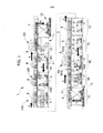
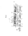
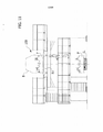
[0020] - a figura 1 é uma vista em elevação lateral de uma modalidade preferida da instalação de acordo com a invenção,[0020] - figure 1 is a side elevation view of a preferred embodiment of the installation according to the invention,
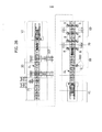
[0021] - a figura 2 é uma vista plana da instalação da figura 1,[0021] - figure 2 is a plan view of the installation of figure 1,
[0022] - a figura 3 é uma vista em perspectiva de um exemplo de uma paleta usada na instalação de acordo com a invenção,[0022] - figure 3 is a perspective view of an example of a pallet used in the installation according to the invention,
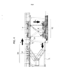
[0023] - a figura 4 é uma vista em elevação lateral mostrando a estação para a transferência vertical de paletas, que conecta a extremidade final da seção superior da linha à extremidade inicial da seção inferior da linha,[0023] - figure 4 is a side elevation view showing the station for the vertical transfer of pallets, which connects the final end of the upper section of the line to the initial end of the lower section of the line,
[0024] -a figura 5 é uma vista em elevação em um plano transversal com respeito à direção longitudinal da linha, mostrando uma estação no início da seção inferior da linha, onde uma sub-paleta dianteira pode ser descarregada a partir de uma respectiva paleta movendo-se ao longo da linha,[0024] - figure 5 is a view in elevation in a transverse plane with respect to the longitudinal direction of the line, showing a station at the beginning of the lower section of the line, where a front sub-palette can be unloaded from a respective palette moving along the line,
[0025] -a figura 6 é uma vista em elevação, ainda em um plano transversal com respeito à direção longitudinal da linha, mostrando uma subsequente estação na qual uma paleta respectiva pode ser carregada ou descarregada com uma sub- paleta inferior e carregada com uma sub-paleta dianteira,[0025] - figure 6 is an elevation view, still in a transverse plane with respect to the longitudinal direction of the line, showing a subsequent station in which a respective pallet can be loaded or unloaded with a lower sub-pallet and loaded with a front sub-palette,
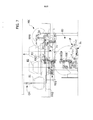
[0026] - a figura 7 é uma vista em elevação em um pano transversal com respeito à direção longitudinal da instalação, mostrando - no nível superior - uma estação na qual um corpo é descarregado sobre uma respectiva paleta e - no nível inferior - uma estação na qual robôs, adaptados para engatar unidades de mola de uma suspensão dianteira suportada pelas paletas de modo a levá-las para uma configuração adaptada para a montagem sobre o respectivo corpo, são providos.[0026] - figure 7 is a view in elevation in a transversal cloth with respect to the longitudinal direction of the installation, showing - on the upper level - a station in which a body is unloaded on a respective pallet and - on the lower level - a station in which robots, adapted to engage spring units of a front suspension supported by the pallets in order to take them into a configuration adapted for mounting on the respective body, are provided.
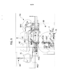
[0027] - a figura 8 é uma vista em elevação lateral mostrando a estação de transferência vertical através da qual uma respectiva paleta na extremidade da seção inferior da linha é elevada até o início da seção superior,[0027] - figure 8 is a side elevation view showing the vertical transfer station through which a respective palette at the end of the lower section of the line is raised to the beginning of the upper section,
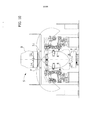
[0028] - a figura 9 mostra - em um plano transversal com respeito à direção longitudinal da linha - a estação ao longo da seção superior da linha, em que os corpos são descarregados sobre as paletas que se movem ao longo da linha,[0028] - figure 9 shows - in a transversal plane with respect to the longitudinal direction of the line - the station along the upper section of the line, in which the bodies are unloaded on the pallets that move along the line,
[0029] - a figura 10 é uma vista em um plano transversal à direção longitudinal da linha mostrando a estação de aparafusamento provida ao longo da seção superior da linha, em que as partes mecânicas providas sobre a paleta são aparafusadas no respectivo corpo através de uma intervenção - a partir da base - de dispositivos de aparafusamento providos no plano inferior da instalação, que, no exemplo ilustrado, são suportados pelos robôs,[0029] - figure 10 is a view in a plane transversal to the longitudinal direction of the line showing the screwing station provided along the upper section of the line, in which the mechanical parts provided on the pallet are screwed into the respective body through a intervention - from the base - of screwing devices provided in the lower plane of the installation, which, in the example shown, are supported by robots,
[0030] - a figura 11 é uma outra vista em seção transversal, mostrando uma estação de reserva onde um operador pode intervir manualmente, quando requerido, para completar o aparafusamento de uma ou mais partes, com respeito às quais um aparafusamento inadequado dos respectivos parafusos foi sinalizado,[0030] - figure 11 is another view in cross section, showing a reserve station where an operator can intervene manually, when required, to complete the screwing of one or more parts, with respect to which an inadequate screwing of the respective screws was flagged,
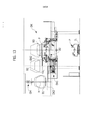
[0031] - a figura 12 é uma vista em seção transversal mostrando uma subsequente estação posicionada ao longo da seção superior da linha, na qual os operadores podem aparafusar manualmente algumas partes mecânicas que requerem uma intervenção a partir de cima,[0031] - figure 12 is a cross-sectional view showing a subsequent station positioned along the top section of the line, in which operators can manually screw in some mechanical parts that require intervention from above,
[0032] - a figura 13 é uma vista em seção transversal mostrando - no nível superior - a estação na qual a separação entre o corpo já completado com as partes aparafusadas no mesmo, a partir da respectiva paleta, que então permanece vazio e livre para ser levado de volta para o início da seção inferior da linha é executada, e[0032] - figure 13 is a cross-sectional view showing - at the top level - the station in which the separation between the body already completed with the parts screwed into it, from the respective palette, which then remains empty and free for be taken back to the beginning of the bottom section of the line is performed, and
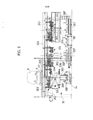
[0033] - a figura 14 é uma variante da figura 1 mostrando uma versão da instalação onde os dispositivos de aparafusamento usados na estação de aparafusamento são atuados manualmente pelos operadores.[0033] - figure 14 is a variant of figure 1 showing a version of the installation where the screwing devices used in the screwing station are operated manually by the operators.
[0034] Nas figuras 1, 2, uma instalação para montar veículos motores é indicada em sua totalidade com o número de referência 1. A instalação 1 compreende uma linha transportadora que segue um trajeto sem fim em um plano vertical, com uma seção inferior, indicada em sua totalidade com o número de referência 1L, ao longo da qual paletas P são transportadas em sucessão em uma primeira direção (da direita para a esquerda com referência aos desenhos) e uma seção superior, indicada em sua totalidade com 1U, superposta em uma distância apropriada sobre a seção inferior 1L e alinhada na mesma direção. Ao longo da seção superior 1U, as paletas P se movem em uma direção oposta à direção de movimento das paletas ao longo da seção inferior 1L (isto é, da esquerda para a direita com referência aos desenhos). A direção de movimento das paletas na instalação 1 está indicada pelas setas A na figura 1.[0034] In figures 1, 2, an installation for assembling motor vehicles is indicated in its entirety with the
[0035] Uma estação de transferência vertical V1 com um dispositivo de elevação que eleva uma respectiva paleta P desde a seção inferior 1L para a seção superior 1U é provida na extremidade final da seção inferior 1L da linha transportadora. Analogamente, uma estação de transferência vertical V2 com um dispositivo de elevação capaz de abaixar uma respectiva paleta P desde a seção superior 1U para a seção inferior 1L é provida na extremidade final da seção superior 1U.[0035] A vertical transfer station V1 with a lifting device that lifts a respective pallet P from the
[0036] Como ilustrado em detalhe daqui em diante, ao longo da seção inferior 1L, uma paleta inicialmente vazia P recebe progressivamente as partes mecânicas destinadas a serem montadas em um respectivo corpo de veículo motor.[0036] As illustrated in detail hereinafter, along the
[0037] O termo “partes mecânicas” é usado na presente descrição e nas reivindicações que seguem para indicar tanto o motor do veículo motor como também qualquer outra parte mecânica destinada a ser montada no corpo do veículo motor, tal como, em particular, elementos de suspensão dianteiro e traseiro, incluindo as molas e os absorvedores de choque, bem como os componentes de transmissão associados com a unidade de motor.[0037] The term "mechanical parts" is used in the present description and in the claims that follow to indicate both the motor of the motor vehicle and also any other mechanical part intended to be mounted on the body of the motor vehicle, such as, in particular, elements front and rear suspension, including springs and shock absorbers, as well as the transmission components associated with the engine unit.
[0038] Na extremidade da seção inferior 1L da linha, uma respectiva paleta P com todas as partes mecânicas montadas sobre a mesma é transferida na estação V1 para a seção superior 1U, antes de ser movida para uma estação MX da seção superior onde a associação (ou “casamento”) de um respectivo corpo B com as várias partes mecânicas montadas sobre a paleta é executada.[0038] At the end of the
[0039] Uma estação de aparafusamento S - na qual as partes mecânicas carregadas pela paleta são aparafusadas no respectivo corpo B usando dispositivos de aparafusamento D que são providos ao longo da seção inferior 1L, ao longo da seção superior 1U da linha - é provida abaixo da estação de aparafusamento S. No exemplo ilustrado na figura 1, os dispositivos de aparafusamento são dispositivos de aparafusamento elétricos suportados por robôs de manipulação R, embora seja possível, como observável, prover que tal aparafusamento seja executado - através de dispositivos de aparafusamento elétricos manualmente controlados - por operadores posicionados ao longo da seção inferior 1L da linha, abaixo da estação S.[0039] A screwing station S - in which the mechanical parts loaded by the pallet are screwed into the respective body B using screwing devices D which are provided along the
[0040] Uma estação DX na qual a separação (ou “divórcio” de um respectivo corpo B, com as partes mecânicas aparafusadas no mesmo, a partir de uma respectiva paleta P é provida na porção final da seção superior 1U da linha, imediatamente antes da estação de transferência vertical V2. A paleta P então descarregada atinge a estação de transferência vertical V2, através da qual ela é abaixada para o nível da seção inferior 1L, onde está novamente pronta para receber as partes mecânicas destinadas a serem aparafusadas em um novo corpo.[0040] A DX station in which the separation (or “divorce” of a respective body B, with the mechanical parts screwed into it, from a respective P pallet is provided in the final portion of the
[0041] A instalação ilustrada nas figuras 1, 2 é provida para ter uma alta flexibilidade operativa, dado que ela é capaz de operar simultaneamente em diferentes tipos e/ou diferentes modelos e/ou diferentes versões de veículos motores. Primeiro e principalmente, isto é alcançado pela provisão de uma arquitetura modular para cada paleta P, permitindo assim adaptar facilmente e rapidamente cada paleta para receber as partes mecânicas dos diferentes tipos de veículos motores, com os quais a linha deve operar.[0041] The installation illustrated in figures 1, 2 is provided to have a high operational flexibility, since it is capable of operating simultaneously in different types and / or different models and / or different versions of motor vehicles. First and foremost, this is achieved by providing a modular architecture for each P pallet, thus allowing each pallet to be easily and quickly adapted to receive the mechanical parts of the different types of motor vehicles with which the line must operate.
[0042] A figura 3 mostra uma modalidade preferida para a arquitetura modular de cada paleta P. de acordo com tal solução, um elemento de paleta principal P1 - formado por uma plataforma de base na forma de uma armação de metal, ou tendo uma porção dianteira P1F e uma porção traseira P1R conectadas uma com a outra por uma porção intermediária mais estreita P11 - é provido. A estrutura de paleta P compreende ainda uma sub-paleta dianteira SBF e uma sub-paleta traseira SBR que são acopladas e fixadas ao mesmo elemento de base P1 nas porções P1F e P1R da mesma. Ambas as sub-paletas SBF, SBR e as porções intermediárias P1I do elemento de base P1 são providas com uma pluralidade de suportes de referência LO usados para suportar e posicionar - na posição de montagem apropriada - uma pluralidade de partes mecânicas, particularmente entre as quais estão o motor, os elementos de suspensão dianteiro e traseiro e os componentes de transmissão de um veículo motor.[0042] Figure 3 shows a preferred modality for the modular architecture of each pallet P. According to such a solution, a main pallet element P1 - formed by a base platform in the form of a metal frame, or having a portion front P1F and a rear portion P1R connected to each other by a narrower intermediate portion P11 - is provided. The pallet structure P further comprises a front sub-pallet SBF and a rear sub-pallet SBR which are coupled and fixed to the same base element P1 in the portions P1F and P1R thereof. Both the SBF, SBR sub-palettes and the intermediate portions P1I of the base element P1 are provided with a plurality of LO reference supports used to support and position - in the appropriate mounting position - a plurality of mechanical parts, particularly among which there are the engine, the front and rear suspension elements and the transmission components of a motor vehicle.
[0043] Devido à arquitetura modular previamente descrita de cada paleta P, a instalação 1 de acordo com a invenção pode ser facilmente adaptada para operar em diferentes tipos ou modelos ou versões de veículos motores. O elemento de base principal P1 da paleta P é adaptado para receber uma pluralidade de tipos diferentes de sub-paletas dianteira e traseira, por vez adaptadas para os respectivos tipos de veículos motores. Cada uma das sub-paletas acima mencionadas SBF, SBR podem, por vez, ser providas tanto com suportes de referência LO correspondendo a um dado tipo de veículo motor quanto com suportes correspondendo a outro tipo. Em particular, cada sub-paleta SBF é usada para carregar sobre a mesma suspensão dianteira de um correspondente tipo de veículo motor e diferentes tipos de motores, enquanto a sub-paleta SBR é usada para descarregar diferentes tipos de suspensões traseiras. A versatilidade de cada sub- paleta em combinação com a provisão de diferentes tipos de sub-paletas rapidamente intercambiáveis uma com respeito à outra permite a obtenção de flexibilidade de produção elevada, permitindo o uso da instalação 1 para a produção simultânea de uma pluralidade de diferentes tipos/modelos/versões de veículos motores. A outra grande vantagem de prover as sub-paletas está situada no fato de que as partes mecânicas podem ser pré-montadas sobre as mesmas fora de linha, então a montagem sobre o elemento de base P1 é realizada com uma operação simples e rápida para cada uma de ditas sub-paletas.[0043] Due to the previously described modular architecture of each P pallet,
[0044] Ainda com referência à figura 3, a paleta P é preferivelmente provida, tanto na porção intermediária P11 do elemento de base P1 quanto nas sub-paletas SBF, SBR, com eixos verticais que podem girar livremente sobre a paleta (não ilustrada), que servem como eixo de transmissão, que permitem o aparafusamento de várias partes mecânicas em um respectivo corpo pelo engate dos dispositivos de aparafusamento na extremidade de ditos eixos rotativos que se projetam abaixo da paleta. Tal solução é por si conhecida a partir da patente prévia GB 2 136 330 A da mesma Depositante.[0044] Still with reference to figure 3, the palette P is preferably provided, both in the intermediate portion P11 of the base element P1 and in the sub-palettes SBF, SBR, with vertical axes that can rotate freely on the palette (not shown) , which serve as a transmission shaft, which allow the screwing of several mechanical parts in a respective body by engaging the screwing devices at the end of said rotary axes that project below the pallet. Such a solution is itself known from the previous patent GB 2 136 330 A of the same Depositor.
[0045] Os dispositivos que acionam e controlam o movimento para frente das paletas P ao longo da seção inferior e da seção superior 1L, 1U da linha podem ser obtidos de qualquer maneira conhecida, mas preferivelmente eles compreendem uma linha de roletes acionados, preferivelmente do tipo formando um objeto da patente norte-americana US 6966427, US 7232027 de propriedade da empresa subsidiária da Depositante. Ainda preferivelmente, o movimento para frente e o posicionamento preciso das paletas P ao longo da linha é obtido por meio de dispositivos vendidos sob as marcas “VERSADRIVE” e “VERSACODER” pela Depositante (ver, também, W02005005290).[0045] The devices that activate and control the forward movement of the P pallets along the lower section and the
[0046] As figuras 4-13 dos desenhos anexos mostram em mais detalhe e em escala ampliada as estações principais da instalação 1 das figurasl, 2.[0046] Figures 4-13 of the accompanying drawings show in more detail and on an enlarged scale the main stations of
[0047] A figura 4 ilustra o detalhe da estação de transferência vertical V2, através da qual uma respectiva paleta P pode ser abaixada a partir do nível da seção superior 1U para o nível da seção inferior 1L. O dispositivo de transferência para o movimento vertical da paleta na estação de transferência V2 pode ser de qualquer tipo conhecido, mas, no caso ilustrado, é especificamente do tipo formando um objeto da patente Européia EP 1 612 183 B1 da Depositante, que provê um pantógrafo em forma de X, controlado por um sistema de guincho por correia. Os detalhes de construção de tal dispositivo não são ilustrados mais detalhadamente na figura 4, tanto para tornar o último mais simples quanto mais claro e devido ao fato que, como mencionados, eles são conhecidos por si a partir do documento de arte anterior previamente mencionado. A figura 4 mostra também a parte da instalação 1 imediatamente à esquerda da estação V2 (com referência ao desenho), que compreende - no nível superior - uma estação DX, que deve ser descrita daqui em diante, onde a seção do corpo que sai da instalação é executada pela respectiva paleta, enquanto no nível inferior é provida com uma estação de espera 20.[0047] Figure 4 illustrates the detail of the vertical transfer station V2, through which a respective pallet P can be lowered from the level of the
[0048] A figura 5 é uma vista em escala ampliada, de acordo com uma seção transversal na direção longitudinal da linha, da estação indicada com 30 na figura 1. A estação 30 é provida no início da seção inferior 1L da linha com a ajuda de carregamento da sub-paleta frontal SBF por meio de um respectivo elemento de base P1 de uma paleta. Um dispositivo de captação 301 (ilustrado na figura 5 em suas várias posições operativas) que é associado a um transportador aéreo 302 montado acima da estação 30, abaixo do piso da seção superior sobrejacente 1U da linha, é provido na estação 30 para tal finalidade. O transportador aéreo 302 provê um carrinho com rodas 303, móvel sobre trilhas elevadas que se estendem transversalmente com respeito à direção longitudinal da linha. O dispositivo de captação 301 compreende um pantógrafo em forma de X suportando - no seu lado inferior - braços verticais 305 providos - em suas extremidades inferiores - com componentes de acoplamento 306 de qualquer tipo, adaptados para acoplar e/ou prender uma sub-paleta dianteira SBF. Os detalhes de construção relativos ao transportador aéreo 302 não são ilustrados aqui, na medida em que eles podem ser obtidos de qualquer maneira conhecida. O mesmo caso se aplica ao dispositivo de elevação 304 e ao dispositivo de controle associado ao mesmo. Através de dito transportador aéreo, o dispositivo de captação 301 pode ser movido transversalmente com respeito à linha e posicionado tanto em uma posição que está situada sobre a seção inferior 1L da linha (a posição esquerda extrema na figura 5), na qual ele pode captar uma sub-paleta vazia SBF, quanto em uma posição posicionada ao lado da linha (no centro na figura 5, em que o dispositivo de elevação 304 pode abaixar a sub-paleta SBF acima de uma extremidade de um transportador 307 (por exemplo, um transportador de rolos) para coletar as sub- paletas vazias (ver também a figura 2B). Por fim, o transportador 301 pode também ser posicionado em uma posição de manutenção (a posição direita extrema na figura 5) onde um operador - em uma plataforma elevada (ver a figura 5) realiza as operações exigidas.[0048] Figure 5 is an enlarged scale view, according to a cross section in the longitudinal direction of the line, of the station indicated with 30 in figure 1.
[0049] A figura 5 ilustra também um transportador de derivação BY que conecta o transportador 307 da estação 30 ao transportador 407 (descrita daqui em diante) da estação subsequente 40.[0049] Figure 5 also illustrates a BY bypass conveyor that connects
[0050] A figura 6 mostra, em uma seção transversal com respeito à direção longitudinal da linha, a estação subsequente 40 da seção inferior 1L, onde é provido um dispositivo de captação 401, inteiramente análogo àquele ilustrado na figura 5 para a estação 30 (ilustrada na figura 6 nas suas várias posições operativas), que carrega - sobre o elemento de base P1 da paleta - uma nova sub-paleta dianteira SBF cheia de componentes mecânicos previamente carregados sobre a mesma. A sub-paleta cheia SBF é captada por um transportador 407 (ver também a figura 2B) usado para acumular as sub-paletas cheias, e assim descarregadas sobre o elemento P1.[0050] Figure 6 shows, in a cross section with respect to the longitudinal direction of the line, the
[0051] Na figura 6, as partes correspondendo àquelas da figura 5 são indicadas usando o mesmo número de referência, exceto pela substituição do número inicial 3 por o número inicial 4.[0051] In figure 6, the parts corresponding to those in figure 5 are indicated using the same reference number, except for the replacement of the initial number 3 by the initial number 4.
[0052] Também neste caso, o transportador aéreo 402 é montado abaixo do piso da seção superior sobrejacente 1U da linha.[0052] Also in this case, the air carrier 402 is mounted below the floor of the overlying
[0053] O dispositivo de captação 401 pode ser posicionado acima da linha 1L (posição esquerda extrema na figura 6) para depositar - sobre o elemento de base P1 da paleta - uma nova sub-paleta dianteira SBF cheia de componentes mecânicos previamente carregados sobre a mesma, ou acima de uma extremidade do transportador 407 (posição central na figura 6), ou em uma estação de manutenção, ilustrada na posição direita extrema na figura 6, onde um operador - em uma plataforma elevada - pode realizar as operações de manutenção, de uma maneira análoga àquela descrita acima com respeito à estação 30.[0053] The
[0054] Por fim, a seção 40 também provê o descarregamento de uma sub-paleta traseira vazia SBR e o carregamento de uma sub-paleta traseira SBR cheia de componentes mecânicos previamente carregados sobre a mesma, ambas as operações sendo realizadas por meio de um robô de manipulação R40 que transfere a sub-paleta traseira SBR desde o elemento de base P1 da paleta P que é posicionado na linha para um transportador 408 que é posicionado ao lado da linha ou, vice-versa, a partir do transportador 408 para o elemento de base P1 das paletas, que é posicionado na linha.[0054] Finally,
[0055] Além disto, deve ser também observado que as captações 301, 302 das estações 30 e 40 podem também ser usadas como reservas mútuas, sem afetar o tempo de ciclo. O transportador de derivação BY que conecta diretamente os transportadores 307, 407 é principalmente usado para tal finalidade.[0055] In addition, it should also be noted that the
[0056] Movendo-se ao longo da seção inferior 1L da linha, uma respectiva paleta P, depois de atravessar as estações 30 e 40, é assim provida com as sub-paletas SBF, SBR e as respectivas partes mecânicas (motor, suspensão dianteira e suspensão traseira). A linha também permite carregar manualmente outras partes mecânicas, tais como silenciadores, radiadores frontais, e outros componentes, dependendo das exigências específicas do fabricante dos veículos motores.[0056] Moving along the
[0057] A jusante da estação 40, as paletas P que se movem ao longo da seção inferior da linha 1L passam através de uma estação passiva, deixada livre para permitir a realização de possível manutenção ou intervenções de reserva e assim através das estações 60 e 70 (ver a figura 1, 2B) que são posicionadas abaixo da estação de aparafusamento S provida no nível superior e que são ocupadas pelos robôs R destinados a aparafusar as partes mecânicas nos corpos que são posicionados no nível superior.[0057] Downstream of
[0058] Uma estação 80, na qual um ou mais robôs de manipulação R80 (ver as figuras 1 e 7) podem ser usados para outras operações, por exemplo, prover componentes, tais como molas de suspensão na configuração de montagem apropriada, é provida a jusante das estações 60, 70, ao longo da seção inferior 1L da linha. A figura 7 também mostra a estação sobrejacente MX, que deve ser ilustrada daqui em diante.[0058] A
[0059] Com referência à figura 8, a jusante da estação 80, a seção inferior 1L da linha provê uma estação 90 que é uma estação de controle na qual é realizado o controle do posicionamento apropriado das partes mecânicas a serem montadas no respectivo corpo e a configuração de algumas unidades móveis montadas sobre a paleta para garantir a adaptabilidade da paleta a diferentes modelos. Preferivelmente, tal controle é executado, de acordo com a invenção, por meio de um sistema de visão automático, vendido sob a marca “VERSAVISION” pela Depositante, que inclui um sistema de controle adaptado para comparar a imagem obtida a partir de uma câmera com uma imagem de referência memorizada no sistema.[0059] With reference to figure 8, downstream of
[0060] A estação de transferência vertical V1 usando um dispositivo de transferência inteiramente análogo àquele usado na estação V2 descrita previamente, para transferir a paleta P com todas as partes mecânicas montadas sobre a mesma para o nível da seção superior 1U da linha, é provida a jusante da estação 90.[0060] The vertical transfer station V1 using a transfer device entirely analogous to that used in the V2 station described previously, to transfer the P pallet with all the mechanical parts mounted on it to the level of the
[0061] A paleta P com todas as partes mecânicas montadas sobre a mesma pode assim ser transportada para uma estação MX onde um respectivo corpo é depositado sobre a mesma. Para esta finalidade, a estação MX é provida com um dispositivo de elevação MX1 arranjado ao lado da linha e provido com garfos MX2 móveis transversalmente em um lado ou no outro do dispositivo de elevação. Através de tais garfos, o dispositivo de elevação pode captar um corpo B1 enganchado no dispositivo de suporte do tipo de gancho H de uma linha aérea OH e primeiro transfere-o acima do dispositivo de elevação MX1 para uma posição B2 e então, através de um movimento dos garfos MX2, para a posição final B3 acima da paleta, onde o corpo pode ser abaixado sobre as paletas e sobre as partes mecânicas suportadas sobre a mesma pelo abaixamento do dispositivo de elevação MX1. Durante tal operação final de associação do corpo às partes mecânicas, quatro robôs RMX guiam os absorvedores de choque e as molas de suspensão para dentro das respectivas sedes sobre o corpo (ver também a figura 2).[0061] The P pallet with all the mechanical parts mounted on it can thus be transported to an MX station where a respective body is deposited on it. For this purpose, the MX station is provided with an MX1 lifting device arranged next to the line and provided with movable MX2 forks transversely on one side or the other of the lifting device. Through such forks, the lifting device can pick up a body B1 hooked onto the hook-type support device H of an OH overhead and first transfer it above the lifting device MX1 to a position B2 and then, through a movement of the MX2 forks, to the final position B3 above the pallet, where the body can be lowered on the pallets and on the mechanical parts supported on it by lowering the MX1 lifting device. During this final operation of associating the body with the mechanical parts, four RMX robots guide the shock absorbers and suspension springs into the respective seats on the body (see also figure 2).
[0062] A figura 10 ilustra em seção transversal a estação de aparafusamento S na qual os dispositivos de aparafusamento de robô providos no plano inferior engatam - a partir de baixo - as extremidades inferiores dos eixos de transmissão livremente giráveis sobre a paleta P, que é posicionada no plano superior, de modo a girar os parafusos associados à extremidade superior de tais eixos e assim fixam as várias partes mecânicas montadas sobre a paleta ao corpo B que é posicionado na estação de aparafusamento S.[0062] Figure 10 illustrates in cross section the screwing station S in which the robot screwing devices provided in the lower plane engage - from below - the lower ends of the freely rotatable transmission shafts on the P pallet, which is positioned in the upper plane, in order to turn the screws associated with the upper end of such axes and thus fix the various mechanical parts mounted on the pallet to the body B which is positioned in the screwing station S.
[0063] A figura 11 ilustra em seção transversal uma estação subsequente 150 (ver também a figura 1) na qual um ou mais operadores podem intervir manualmente para repetir e/ou completar o aparafusamento de uma ou mais partes, com relação às quais um aparafusamento inadequado pelo robô R na estação S foi sinalizado.[0063] Figure 11 illustrates in cross section a subsequent station 150 (see also figure 1) in which one or more operators can intervene manually to repeat and / or complete the screwing of one or more parts, with respect to which a screwing inadequate by robot R at station S has been signaled.
[0064] A figura 12 é uma seção transversal de uma outra estação 160, na qual operadores W executam manualmente as operações de aparafusamento, que requerem uma outra intervenção a partir de cima, para completar a montagem das partes mecânicas.[0064] Figure 12 is a cross section of another
[0065] A figura 13 é uma vista em seção transversal em escala ampliada da estação de “divórcio” DX, na qual o corpo com as partes mecânicas aparafusadas sobre a mesma é separado das respectivas paletas P. isto é obtido por meio de um dispositivo de elevação de garfo DX1 inteiramente análogo ao dispositivo de elevação MX1 provido na estação de “casamento” MX. Assim, na figura 13, as partes que correspondem àquelas da figura 9 são indicadas usando os mesmos números de referência, exceto para a substituição da letra M pela letra D. assim, o corpo pode ser transportado a partir da posição B3 a cima da linha para uma posição intermediária B2 através dos garfos DX2 e então a partir de tal posição intermediária B2 para uma posição B1 acima de um dispositivo de suporte do tipo de gancho H suportado por uma linha transportadora aérea OH, que move o corpo com as partes mecânicas aparafusadas no mesmo para fora da instalação, para as subsequentes operações de montagem.[0065] Figure 13 is a cross-sectional view on an enlarged scale of the DX “divorce” station, in which the body with the mechanical parts screwed on it is separated from the respective pallets P. This is obtained by means of a device fork lift system DX1 entirely analogous to the MX1 lift device provided in the MX “wedding” station. Thus, in figure 13, the parts corresponding to those in figure 9 are indicated using the same reference numbers, except for the replacement of the letter M by the letter D. Thus, the body can be transported from position B3 above the line to an intermediate position B2 through the forks DX2 and then from such an intermediate position B2 to a position B1 above a support device of the type H hook supported by an overhead conveyor line OH, which moves the body with the screwed mechanical parts it out of the installation, for subsequent assembly operations.
[0066] A arquitetura geral da instalação de acordo com a invenção é inteiramente flexível, dado que uma ou mais seções da linha que provêem robôs com seções onde intervenções manuais pelos operadores são providas, podem ser substituídas. Um exemplo deste tipo é ilustrado na figura 14, onde a instalação inclui uma seção de linha ML onde as várias partes mecânicas são carregadas manualmente sobre as paletas que se movem ao longo da seção inferior da linha, e uma seção MB onde a operação de aparafusamento das partes mecânicas sobre os corpos que se movem ao longo da seção superior da linha é executada manualmente.[0066] The general architecture of the installation according to the invention is entirely flexible, given that one or more sections of the line that provide robots with sections where manual interventions by operators are provided, can be replaced. An example of this type is illustrated in figure 14, where the installation includes a section of ML line where the various mechanical parts are loaded manually onto the pallets that move along the lower section of the line, and an MB section where the screwing operation of the mechanical parts on the bodies that move along the upper section of the line is performed manually.
[0067] Como ficou claro a partir da descrição acima, a instalação de acordo com a invenção atinge um aperfeiçoamento considerável com respeito à solução prévia proposta pela Depositante (GB2136330A) em termos de redução do espaço ocupado, maior eficiência operativa devido à redução das partes “passivas” das linhas, flexibilidade devida à arquitetura modular de cada paleta bem como da arquitetura modular da linha inteira e fácil acessibilidade de cada estação da linha a partir de seus dois lados, até a vantagem de logística com respeito ao fornecimento das partes. Além da vantagem previamente mencionada de reduzir consideravelmente o espaço ocupado, a provisão da linha para montar as partes mecânicas sobre a paleta e a linha de aparafusamento em uma posição superposta uma à outra permite um uso mais racional de diferentes estações de montagem. Além disto, a escavação de fossos no piso para receber os dispositivos requeridos para o aparafusamento não é necessária.[0067] As was clear from the description above, the installation according to the invention achieves a considerable improvement with respect to the previous solution proposed by the Depositor (GB2136330A) in terms of reducing the space occupied, greater operational efficiency due to the reduction of parts “Passive” of the lines, flexibility due to the modular architecture of each palette as well as the modular architecture of the entire line and easy accessibility of each station of the line from its two sides, up to the logistics advantage with respect to the supply of the parts. In addition to the previously mentioned advantage of considerably reducing the space occupied, the provision of the line to mount the mechanical parts on the pallet and the screwing line in a position superimposed on each other allows a more rational use of different assembly stations. In addition, digging ditches in the floor to receive the devices required for screwing is not necessary.
[0068] Como já ilustrado acima, embora a instalação de acordo com a invenção seja apropriada para usar dispositivos de qualquer tipo conhecido com respeito aos dispositivos para mover as paletas dentro da instalação, a linha de transportador de roletes motorizada que representa uma produção padrão da empresa da Depositante, com sistemas de controle de posição vendidos sob as marcas “VERSADRIVE” e “VERSACODER”, e com a outra provisão de um controle da execução apropriada das operações de montagem através do sistema de visão automático vendido pela Depositante sob a marca “VERSAVISION” é particularmente preferido.[0068] As already illustrated above, although the installation according to the invention is suitable for using devices of any known type with respect to devices for moving pallets within the installation, the motorized roller conveyor line which represents a standard production of Depositor company, with position control systems sold under the brands “VERSADRIVE” and “VERSACODER”, and with the other provision for a control of the proper execution of assembly operations through the automatic vision system sold by the Depositor under the brand “ VERSAVISION ”is particularly preferred.
[0069] Obviamente, sem prejuízo para o princípio da invenção, os detalhes de construção e as modalidades podem variar amplamente com respeito àqueles que foram descritos e ilustrados, a título de exemplo não limitativo, sem fugir do escopo de proteção da presente invenção.[0069] Obviously, without prejudice to the principle of the invention, the details of construction and modalities can vary widely with respect to those that have been described and illustrated, by way of non-limiting example, without departing from the scope of protection of the present invention.
Claims (10)
Applications Claiming Priority (2)
| Application Number | Priority Date | Filing Date | Title |
|---|---|---|---|
| ITTO2009A001054A IT1397438B1 (en) | 2009-12-30 | 2009-12-30 | INSTALLATION FOR THE ASSEMBLY OF MECHANICAL PARTS ON BODIES OF MOTOR VEHICLES |
| ITT02009A001054 | 2009-12-30 |
Publications (2)
| Publication Number | Publication Date |
|---|---|
| BRPI1005531A2 BRPI1005531A2 (en) | 2013-10-22 |
| BRPI1005531B1 true BRPI1005531B1 (en) | 2020-07-14 |
Family
ID=42398234
Family Applications (1)
| Application Number | Title | Priority Date | Filing Date |
|---|---|---|---|
| BRPI1005531-2A BRPI1005531B1 (en) | 2009-12-30 | 2010-12-23 | INSTALLATION FOR ASSEMBLY OF MECHANICAL PARTS ON MOTOR VEHICLE BODIES |
Country Status (8)
| Country | Link |
|---|---|
| US (2) | US9045182B2 (en) |
| EP (1) | EP2340982B1 (en) |
| CN (1) | CN102114594B (en) |
| BR (1) | BRPI1005531B1 (en) |
| ES (1) | ES2392149T3 (en) |
| IT (1) | IT1397438B1 (en) |
| MX (1) | MX2010014313A (en) |
| PL (1) | PL2340982T3 (en) |
Families Citing this family (22)
| Publication number | Priority date | Publication date | Assignee | Title |
|---|---|---|---|---|
| JP5748452B2 (en) * | 2010-11-15 | 2015-07-15 | キヤノン株式会社 | Parts assembly system |
| DE102010055959A1 (en) * | 2010-12-23 | 2012-06-28 | Daimler Ag | Method for assembling motor vehicles |
| ITTO20120241A1 (en) | 2012-03-19 | 2013-09-20 | Cpm S P A | PLANT TO ASSEMBLE MECHANICAL PARTS ON BODIES OF VEHICLES |
| DE102012214127A1 (en) | 2012-08-09 | 2014-02-13 | Torsten Hösker | Overhead conveyor with self-supporting shoring |
| CN102814644A (en) * | 2012-09-10 | 2012-12-12 | 苏州美尔科自动化设备有限公司 | Automatic assembling device of hemodialyzer |
| JP5741618B2 (en) * | 2013-03-19 | 2015-07-01 | 株式会社安川電機 | Workpiece assembly apparatus and assembly method |
| DE102013213223A1 (en) | 2013-07-05 | 2015-01-08 | Torsten Hösker | Overhead conveyor with securing element |
| DE102013213222A1 (en) * | 2013-07-05 | 2015-01-08 | Torsten Hösker | Overhead conveyor with shoring modules |
| DE202013104354U1 (en) | 2013-09-24 | 2013-10-10 | Torsten Hösker | Overhead conveyor for storage on the ceiling of an assembly plant |
| US20150128719A1 (en) * | 2013-11-12 | 2015-05-14 | Comau, Inc. | Assembly line quality control cart and method |
| CN103659267B (en) * | 2013-12-19 | 2016-04-06 | 周俊雄 | The middle shell assembly automatic assembling of adjuster |
| DE202014101003U1 (en) * | 2014-03-06 | 2015-06-17 | Kuka Systems Gmbh | manufacturing plant |
| CN106103006B (en) * | 2014-03-06 | 2019-03-29 | 库卡系统有限责任公司 | Manufacture work station, manufacturing equipment and method |
| EP2923925A3 (en) | 2014-03-27 | 2016-01-13 | Cpm S.P.A. | Universal balance holder for transporting vehicle bodies and transporting plant equipped therewith |
| US10441993B2 (en) | 2015-09-11 | 2019-10-15 | Lear Corporation | Vertical twisting system and method |
| US9561910B1 (en) * | 2016-02-08 | 2017-02-07 | Lear Corporation | Vertical assembly line |
| CN107585225B (en) * | 2017-09-25 | 2023-05-12 | 郑州日产汽车有限公司 | Bearing and non-bearing type vehicle body and vehicle type mixed flow assembly production line |
| IT201900007971A1 (en) | 2019-06-04 | 2020-12-04 | Cpm S P A | CONVEYOR AND CONVEYOR SYSTEM EQUIPPED WITH THIS CONVEYOR, IN PARTICULAR FOR VEHICLE ASSEMBLY LINES |
| US10822043B1 (en) | 2019-06-06 | 2020-11-03 | Mahindra N.A. Tech Center | Method of interconnecting a chassis and a body |
| CN110666809A (en) * | 2019-09-19 | 2020-01-10 | 浙江科技学院 | Tree planting robot |
| IT202000016303A1 (en) | 2020-07-06 | 2022-01-06 | Cpm S P A | SCREWING CHUCK FOR AN ASSOCIATED VEHICLE AND PALLET ASSEMBLY PLANT EQUIPPED WITH THE SAME |
| IT202000016309A1 (en) | 2020-07-06 | 2022-01-06 | Cpm S P A | GUIDED FEED SCREWING CHUCK FOR AN ASSOCIATED VEHICLE AND PALLET ASSEMBLY PLANT EQUIPPED WITH THE SAME |
Family Cites Families (23)
| Publication number | Priority date | Publication date | Assignee | Title |
|---|---|---|---|---|
| US2804962A (en) * | 1955-09-12 | 1957-09-03 | Smith Corp A O | Apparatus for automatically fabricating vehicle frames |
| SE373811B (en) * | 1972-05-19 | 1975-02-17 | Volvo Ab | |
| IT1158820B (en) * | 1983-03-04 | 1987-02-25 | Comau Spa | PROGRAMMABLE SYSTEM FOR ASSEMBLY BY SCREWING THE VARIOUS MECHANICAL PARTS THE VEHICLES TO THEIR RESPECTIVE BODIES |
| KR970003573B1 (en) * | 1990-12-28 | 1997-03-20 | 마쓰다 가부시끼가이샤 | Method for the assembly of automotive vehicle |
| IT1261269B (en) * | 1993-09-20 | 1996-05-09 | Comau Spa | POINT WELDING DEVICE FOR STRUCTURES CONSISTING OF PRINTED SHEET ELEMENTS, IN PARTICULAR MOTOR VEHICLE BODIES |
| DE19523294A1 (en) * | 1995-06-27 | 1997-01-02 | Opel Adam Ag | System for joining the chassis units to the body of a motor vehicle |
| US5736609A (en) | 1995-06-30 | 1998-04-07 | Mitsui Toatsu Chemicals, Inc. | Sulfur-containing urethane-based resin composition, its resin, and optical element and lens comprising resin |
| US6109424A (en) * | 1997-03-20 | 2000-08-29 | Fori Automation, Inc. | Chassis/body marriage lift machine |
| DE29721038U1 (en) * | 1997-11-28 | 1999-04-01 | Ekuma Werkzeug & Maschbau | System for installing vehicle parts in a body |
| US6554119B2 (en) * | 2000-02-07 | 2003-04-29 | Progressive Tool & Industries Co. | Flexible automotive assembly line and method |
| US6494304B1 (en) * | 2000-08-15 | 2002-12-17 | Jervis B. Webb Company | Production operation with power and free pallet conveyor |
| DE10121053A1 (en) * | 2001-04-28 | 2002-10-31 | Duerr Systems Gmbh | Conveying device for conveying workpieces through a treatment area for surface treatment of the workpieces |
| JP4039114B2 (en) * | 2001-09-26 | 2008-01-30 | 日産自動車株式会社 | Car body assembling method and car body assembling apparatus |
| GB0125079D0 (en) * | 2001-10-18 | 2001-12-12 | Cimac Automation Ltd | Auto motion:robot guidance for manufacturing |
| US6966427B2 (en) | 2003-04-04 | 2005-11-22 | Progressive Tool & Industries Co. | Pallet/skid power roll system |
| WO2005005290A2 (en) | 2003-06-30 | 2005-01-20 | Progressive Tool & Industries, Co. | A precise transport posiitoning apparatus using a closed loop controlled, non-direct drive or friction drive system with absolute positioning encoder |
| CN1819966B (en) * | 2003-07-01 | 2011-07-27 | 本田技研工业株式会社 | Device of transporting and installing component |
| ITFI20040149A1 (en) | 2004-06-29 | 2004-09-29 | Stempa Di Mario Gonzi | LOAD LIFTING DEVICE |
| US8365794B2 (en) * | 2005-01-18 | 2013-02-05 | Android Industries Llc | Inflation work station |
| WO2008002749A2 (en) * | 2006-06-28 | 2008-01-03 | Utica Enterprises, Inc. | Assembly line vehicle body positioning |
| DE602006003748D1 (en) * | 2006-07-19 | 2009-01-02 | Comau Spa | Cell for automated assembly operations |
| KR100792891B1 (en) * | 2006-10-10 | 2008-01-08 | 현대자동차주식회사 | Jig for assembling various vehicle's front end module |
| CN101311054A (en) * | 2007-05-25 | 2008-11-26 | 南通中集特种运输设备制造有限公司 | Assembly method of transporter platform and work platform thereof |
-
2009
- 2009-12-30 IT ITTO2009A001054A patent/IT1397438B1/en active
-
2010
- 2010-12-07 ES ES10193941T patent/ES2392149T3/en active Active
- 2010-12-07 PL PL10193941T patent/PL2340982T3/en unknown
- 2010-12-07 EP EP10193941A patent/EP2340982B1/en active Active
- 2010-12-20 MX MX2010014313A patent/MX2010014313A/en active IP Right Grant
- 2010-12-20 US US12/973,265 patent/US9045182B2/en active Active
- 2010-12-23 BR BRPI1005531-2A patent/BRPI1005531B1/en active IP Right Grant
- 2010-12-30 CN CN201010614104.3A patent/CN102114594B/en active Active
-
2015
- 2015-04-30 US US14/700,995 patent/US9259815B2/en active Active
Also Published As
| Publication number | Publication date |
|---|---|
| US9045182B2 (en) | 2015-06-02 |
| IT1397438B1 (en) | 2013-01-10 |
| PL2340982T3 (en) | 2013-01-31 |
| EP2340982B1 (en) | 2012-09-19 |
| US20110154654A1 (en) | 2011-06-30 |
| BRPI1005531A2 (en) | 2013-10-22 |
| CN102114594B (en) | 2016-01-20 |
| MX2010014313A (en) | 2011-07-27 |
| US20150239078A1 (en) | 2015-08-27 |
| US9259815B2 (en) | 2016-02-16 |
| CN102114594A (en) | 2011-07-06 |
| ITTO20091054A1 (en) | 2011-06-30 |
| ES2392149T3 (en) | 2012-12-05 |
| EP2340982A1 (en) | 2011-07-06 |
Similar Documents
| Publication | Publication Date | Title |
|---|---|---|
| BRPI1005531B1 (en) | INSTALLATION FOR ASSEMBLY OF MECHANICAL PARTS ON MOTOR VEHICLE BODIES | |
| KR101672569B1 (en) | System for replacing a battery of a ground transportation vehicle, particularly of an unmanned heavy-duty transportation vehicle for iso containers | |
| ES2320171T3 (en) | SYSTEM FOR ASSEMBLY BODY STRUCTURES OF MOTOR VEHICLES OR SUB-ASSEMBLIES OF THE SAME. | |
| KR100696296B1 (en) | Vehicle-moving apparatus for parking facilities | |
| US20170182923A1 (en) | Heavy-duty transport vehicle for containers, in particular iso containers, and method for loading same | |
| US11884314B2 (en) | Laterally operating payload handling device | |
| KR100622066B1 (en) | Carrier system for vehicl assembly line | |
| CN110733817B (en) | Transfer robot | |
| KR101382716B1 (en) | skid-loading device for automotive assemby line | |
| CN107297704B (en) | Fixture for positioning front windshield and application method thereof | |
| JP3743032B2 (en) | Conveyor roller changer | |
| CN214355625U (en) | Power conversion station | |
| JPS6186397A (en) | Service car for aircraft in airport | |
| KR101371447B1 (en) | A storage apparatus for conveying parts of a vehicle | |
| KR101055008B1 (en) | Jig device for fender assembly | |
| CN217598630U (en) | Transfer device for carrying steel drum | |
| CN111470237A (en) | White car body general assembly fixture switching fixture library and operation method thereof | |
| JPS60240388A (en) | Welding and assembling line for vehicle body | |
| CN103979439B (en) | Combined flat weight hanging device, method and counterbalanced weight mounting structure | |
| CN214396482U (en) | Power conversion station | |
| CN219949677U (en) | Automatic base feeding equipment of expansion valve assembly line | |
| CN216781885U (en) | Industrial robot base | |
| CN219905605U (en) | Three-dimensional storage equipment | |
| JP2649600B2 (en) | Roll loading / conveying device | |
| JPH06329060A (en) | Motorcycle assembling method |
Legal Events
| Date | Code | Title | Description |
|---|---|---|---|
| B03A | Publication of an application: publication of a patent application or of a certificate of addition of invention | ||
| B06F | Objections, documents and/or translations needed after an examination request according art. 34 industrial property law | ||
| B06U | Preliminary requirement: requests with searches performed by other patent offices: suspension of the patent application procedure | ||
| B09A | Decision: intention to grant | ||
| B15K | Others concerning applications: alteration of classification |
Free format text: A CLASSIFICACAO ANTERIOR ERA: B62D 65/02 Ipc: B62D 65/18 (2006.01), B23P 21/00 (2006.01), B62D 6 |
|
| B16A | Patent or certificate of addition of invention granted |
Free format text: PRAZO DE VALIDADE: 20 (VINTE) ANOS CONTADOS A PARTIR DE 23/12/2010, OBSERVADAS AS CONDICOES LEGAIS. |