BRPI0912432B1 - METHOD FOR SELECTING AND TRANSMISSION SYSTEM THAT SELECTS A BETTER TRANSMISSION BEAM FROM AN ACCESS NODE TO A RECEIVER IN A COMMUNICATION SYSTEM AND COMMUNICATION SYSTEM - Google Patents
METHOD FOR SELECTING AND TRANSMISSION SYSTEM THAT SELECTS A BETTER TRANSMISSION BEAM FROM AN ACCESS NODE TO A RECEIVER IN A COMMUNICATION SYSTEM AND COMMUNICATION SYSTEM Download PDFInfo
- Publication number
- BRPI0912432B1 BRPI0912432B1 BRPI0912432-2A BRPI0912432A BRPI0912432B1 BR PI0912432 B1 BRPI0912432 B1 BR PI0912432B1 BR PI0912432 A BRPI0912432 A BR PI0912432A BR PI0912432 B1 BRPI0912432 B1 BR PI0912432B1
- Authority
- BR
- Brazil
- Prior art keywords
- beams
- receiver
- access node
- space
- cell
- Prior art date
Links
Images


Classifications
-
- H—ELECTRICITY
- H04—ELECTRIC COMMUNICATION TECHNIQUE
- H04B—TRANSMISSION
- H04B7/00—Radio transmission systems, i.e. using radiation field
- H04B7/02—Diversity systems; Multi-antenna system, i.e. transmission or reception using multiple antennas
- H04B7/04—Diversity systems; Multi-antenna system, i.e. transmission or reception using multiple antennas using two or more spaced independent antennas
- H04B7/0408—Diversity systems; Multi-antenna system, i.e. transmission or reception using multiple antennas using two or more spaced independent antennas using two or more beams, i.e. beam diversity
-
- H—ELECTRICITY
- H04—ELECTRIC COMMUNICATION TECHNIQUE
- H04B—TRANSMISSION
- H04B7/00—Radio transmission systems, i.e. using radiation field
- H04B7/02—Diversity systems; Multi-antenna system, i.e. transmission or reception using multiple antennas
- H04B7/04—Diversity systems; Multi-antenna system, i.e. transmission or reception using multiple antennas using two or more spaced independent antennas
- H04B7/06—Diversity systems; Multi-antenna system, i.e. transmission or reception using multiple antennas using two or more spaced independent antennas at the transmitting station
- H04B7/0686—Hybrid systems, i.e. switching and simultaneous transmission
- H04B7/0695—Hybrid systems, i.e. switching and simultaneous transmission using beam selection
-
- H—ELECTRICITY
- H04—ELECTRIC COMMUNICATION TECHNIQUE
- H04B—TRANSMISSION
- H04B7/00—Radio transmission systems, i.e. using radiation field
- H04B7/02—Diversity systems; Multi-antenna system, i.e. transmission or reception using multiple antennas
- H04B7/04—Diversity systems; Multi-antenna system, i.e. transmission or reception using multiple antennas using two or more spaced independent antennas
- H04B7/06—Diversity systems; Multi-antenna system, i.e. transmission or reception using multiple antennas using two or more spaced independent antennas at the transmitting station
- H04B7/0613—Diversity systems; Multi-antenna system, i.e. transmission or reception using multiple antennas using two or more spaced independent antennas at the transmitting station using simultaneous transmission
- H04B7/0615—Diversity systems; Multi-antenna system, i.e. transmission or reception using multiple antennas using two or more spaced independent antennas at the transmitting station using simultaneous transmission of weighted versions of same signal
- H04B7/0617—Diversity systems; Multi-antenna system, i.e. transmission or reception using multiple antennas using two or more spaced independent antennas at the transmitting station using simultaneous transmission of weighted versions of same signal for beam forming
-
- H—ELECTRICITY
- H04—ELECTRIC COMMUNICATION TECHNIQUE
- H04B—TRANSMISSION
- H04B7/00—Radio transmission systems, i.e. using radiation field
- H04B7/02—Diversity systems; Multi-antenna system, i.e. transmission or reception using multiple antennas
- H04B7/04—Diversity systems; Multi-antenna system, i.e. transmission or reception using multiple antennas using two or more spaced independent antennas
- H04B7/06—Diversity systems; Multi-antenna system, i.e. transmission or reception using multiple antennas using two or more spaced independent antennas at the transmitting station
- H04B7/0613—Diversity systems; Multi-antenna system, i.e. transmission or reception using multiple antennas using two or more spaced independent antennas at the transmitting station using simultaneous transmission
- H04B7/0615—Diversity systems; Multi-antenna system, i.e. transmission or reception using multiple antennas using two or more spaced independent antennas at the transmitting station using simultaneous transmission of weighted versions of same signal
- H04B7/0619—Diversity systems; Multi-antenna system, i.e. transmission or reception using multiple antennas using two or more spaced independent antennas at the transmitting station using simultaneous transmission of weighted versions of same signal using feedback from receiving side
- H04B7/0621—Feedback content
- H04B7/0632—Channel quality parameters, e.g. channel quality indicator [CQI]
-
- H—ELECTRICITY
- H04—ELECTRIC COMMUNICATION TECHNIQUE
- H04B—TRANSMISSION
- H04B7/00—Radio transmission systems, i.e. using radiation field
- H04B7/02—Diversity systems; Multi-antenna system, i.e. transmission or reception using multiple antennas
- H04B7/04—Diversity systems; Multi-antenna system, i.e. transmission or reception using multiple antennas using two or more spaced independent antennas
- H04B7/06—Diversity systems; Multi-antenna system, i.e. transmission or reception using multiple antennas using two or more spaced independent antennas at the transmitting station
- H04B7/0613—Diversity systems; Multi-antenna system, i.e. transmission or reception using multiple antennas using two or more spaced independent antennas at the transmitting station using simultaneous transmission
- H04B7/0615—Diversity systems; Multi-antenna system, i.e. transmission or reception using multiple antennas using two or more spaced independent antennas at the transmitting station using simultaneous transmission of weighted versions of same signal
- H04B7/0619—Diversity systems; Multi-antenna system, i.e. transmission or reception using multiple antennas using two or more spaced independent antennas at the transmitting station using simultaneous transmission of weighted versions of same signal using feedback from receiving side
- H04B7/0636—Feedback format
- H04B7/0639—Using selective indices, e.g. of a codebook, e.g. pre-distortion matrix index [PMI] or for beam selection
-
- H—ELECTRICITY
- H04—ELECTRIC COMMUNICATION TECHNIQUE
- H04L—TRANSMISSION OF DIGITAL INFORMATION, e.g. TELEGRAPHIC COMMUNICATION
- H04L5/00—Arrangements affording multiple use of the transmission path
- H04L5/003—Arrangements for allocating sub-channels of the transmission path
- H04L5/0053—Allocation of signaling, i.e. of overhead other than pilot signals
- H04L5/0057—Physical resource allocation for CQI
-
- H—ELECTRICITY
- H04—ELECTRIC COMMUNICATION TECHNIQUE
- H04W—WIRELESS COMMUNICATION NETWORKS
- H04W52/00—Power management, e.g. TPC [Transmission Power Control], power saving or power classes
- H04W52/04—TPC
- H04W52/30—TPC using constraints in the total amount of available transmission power
- H04W52/32—TPC of broadcast or control channels
- H04W52/325—Power control of control or pilot channels
-
- H—ELECTRICITY
- H04—ELECTRIC COMMUNICATION TECHNIQUE
- H04W—WIRELESS COMMUNICATION NETWORKS
- H04W72/00—Local resource management
- H04W72/50—Allocation or scheduling criteria for wireless resources
- H04W72/54—Allocation or scheduling criteria for wireless resources based on quality criteria
- H04W72/542—Allocation or scheduling criteria for wireless resources based on quality criteria using measured or perceived quality
Abstract
método para selecionar e sistema de transmissão que seleciona um melhor feixe de transmissão a partir de um nó de acesso para um sistema de comunicação. a presente invenção é um método e sistema para suportar um sistema de antena de formação de feixe em uma rede de comunicação de banda larga móvel com um padrão de feixe aperfeiçoado, padrão de varredura de feixe, desenho de canal piloto com regras de retorno e relatório, e desenho de sinalização de controle. especificamente, o padrão de feixe aperfeiçoado inclui um método de suporte de comunicações sem fio em uma rede sem fio formando pelo menos dois feixes espaciais dentro de um segmento de célula onde os pelo menos dois feixes espaciais são associados com níveis diferentes de potência, e separadamente, onde pelo menos dois feixes espaciais podem ser movidos através do segmento de célula de acordo com um único padrão de varredura. o desenho de canal piloto aperfeiçoa o desempenho de largura de banda de rede e aperfeiçoa o rastreamento de mobilidade de usuário. as regras de retorno e relatório podem ser estabelecidas utilizando-se um designador de campo particular, cqi, na modalidade preferida.method for selecting and transmission system that selects a better transmission beam from an access node to a communication system. the present invention is a method and system for supporting a beamforming antenna system on a mobile broadband communication network with an improved beam pattern, beam scan pattern, pilot channel design with feedback and reporting rules , and control signaling design. specifically, the improved beam pattern includes a method of supporting wireless communications on a wireless network forming at least two space beams within a cell segment where the at least two space beams are associated with different power levels, and separately , where at least two space beams can be moved through the cell segment according to a single scan pattern. the pilot channel design improves network bandwidth performance and improves user mobility tracking. the return and reporting rules can be established using a particular field designator, cqi, in the preferred mode.
Description
[001] Esse pedido está relacionado com o pedido de patente provisório No. 61/052.011, depositado em 9 de maio de 2008, e a prioridade é reivindicada para esse depósito anterior sob 35. U.S.C. § 119(e), e esse pedido está relacionado com o pedido PCT No. PCT/US2008/078913 depositado em 6 de outubro de 2008, e a prioridade é reivindicada para esse depósito anterior sob 35 U.S.C. § 120. O pedido de patente provisório e o pedido PCT anterior são incorporados por referência nesse pedido de patente de utilidade.[001] This application is related to provisional patent application No. 61 / 052.011, filed on May 9, 2008, and the priority is claimed for that previous filing under 35. USC § 119 (e), and that application is related to PCT application No. PCT / US2008 / 078913 filed on October 6, 2008, and priority is claimed for that earlier filing under 35 USC § 120. The provisional patent application and the previous PCT application are incorporated by reference into that utility patent application.
[002] A presente invenção refere-se a suporte de formação de feixes espaciais dentro de um segmento de célula.[002] The present invention relates to support for the formation of space bundles within a cell segment.
[003] Existe uma demanda crescente por operadoras sem fio móveis para fornecimento de serviços de voz e dados em alta velocidade, e, ao mesmo tempo, essas operadoras desejam suportar mais usuários por estação base para reduzir os custos gerais de rede e tornar os serviços acessíveis aos assinantes. Como resultado disso, os sistemas sem fio que permitem taxas de dados mais altas e maiores capacidades são necessários. O espectro disponível para serviços sem fio é limitado, no entanto, e as tentativas anteriores de se aumentar o tráfego dentro de uma largura de banda fixa aumentaram a interferência no sistema e degradaram a qualidade de sinal.[003] There is an increasing demand for wireless mobile operators to provide high-speed voice and data services, and at the same time, these operators want to support more users per base station to reduce overall network costs and make services accessible to subscribers. As a result, wireless systems that allow for higher data rates and greater capacities are required. The spectrum available for wireless services is limited, however, and previous attempts to increase traffic within a fixed bandwidth have increased system interference and degraded signal quality.
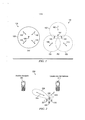
[004] As redes de comunicações sem fio são tipicamente divididas em células, com cada uma das células sendo dividida adicionalmente em setores de célula. Uma estação base é fornecida em cada célula para permitir as comunicações sem fio com faz estações móveis localizadas dentro da célula. Um problema existe quando as antenas onidirecionais da técnica anterior são utilizadas na estação base visto que a transmissão/recepção de cada sinal de usuário se torna uma fonte de interferência para outros usuários localizados no mesmo local de célula na rede, tornando a interferência total do sistema limitada. Tal antena onidirecional é ilustrada na figura 1(a).[004] Wireless communications networks are typically divided into cells, with each cell being further divided into cell sectors. A base station is provided in each cell to enable wireless communications with mobile stations located within the cell. A problem exists when the omni-directional antennas of the prior art are used at the base station since the transmission / reception of each user signal becomes a source of interference for other users located in the same cell location on the network, making total system interference limited. Such an omnidirectional antenna is illustrated in figure 1 (a).
[005] Nesses sistemas de rede celular de antena onidirecional tradicionais, a estação base não tem informação sobre a posição das unidades móveis dentro da célula e irradia o sinal em todas as direções dentro da célula a fim de fornecer cobertura de rádio. Isso resulta em desperdício de energia em transmissões quando não existem unidades móveis a serem alcançadas, em adição a causar interferência para as células adjacentes utilizando a mesma frequência, as chamadas células de mesmo canal. Da mesma forma, na recepção, a antena recebe sinais provenientes de todas as direções incluindo ruído e interferência.[005] In these traditional omnidirectional antenna cellular network systems, the base station has no information on the position of the mobile units within the cell and radiates the signal in all directions within the cell in order to provide radio coverage. This results in wasted energy on transmissions when there are no mobile units to be reached, in addition to causing interference to adjacent cells using the same frequency, so-called cells on the same channel. Likewise, at reception, the antenna receives signals from all directions including noise and interference.
[006] Uma forma eficiente de se aumentar a eficiência de utilização da largura de banda e redução desse tipo de interferência é a utilização da tecnologia de múltiplas entradas e múltiplas saídas (MIMO) que suporta as múltiplas antenas no transmissor e receptor. Para um canal de difusão de múltiplas antenas, tal como downlink em uma rede celular, estratégias de transmissão/recepção têm sido desenvolvidas para maximizar o rendimento em downlink pela divisão da célula em múltiplos setores e utilização de antenas setorizadas para comunicar simultaneamente com múltiplos usuários. Tal tecnologia de antena setorizada oferece uma solução significativamente aperfeiçoada para reduzir os níveis de interferência e aperfeiçoar a capacidade do sistema.[006] An efficient way to increase the efficiency of using the bandwidth and reducing this type of interference is the use of the technology of multiple inputs and multiple outputs (MIMO) that supports the multiple antennas in the transmitter and receiver. For a multi-antenna broadcast channel, such as downlink in a cellular network, transmission / reception strategies have been developed to maximize downlink performance by dividing the cell into multiple sectors and using sectored antennas to communicate simultaneously with multiple users. Such sectored antenna technology offers a significantly improved solution to reduce interference levels and improve system capacity.
[007] O sistema de antena setorizada é caracterizado por um transmissor centralizado (sítio/torre de célula) que comunica simultaneamente com múltiplos receptores (equipamento de usuário, telefone celular, etc.) que são envolvidos na sessão de comunicação. Com essa tecnologia, cada sinal de usuário é transmitido e recebido pela estação base apenas na direção desse usuário em particular. Isso permite que o sistema reduza de forma significativa a interferência geral no sistema. Um sistema de antena setorizada, como ilustrado na figura 1(b), consiste de um conjunto de antenas que direcionam feixes de transmissão/recepção diferentes na direção de usuários localizados na área de cobertura do setor da célula.[007] The sectored antenna system is characterized by a centralized transmitter (cell site / tower) that communicates simultaneously with multiple receivers (user equipment, cell phone, etc.) that are involved in the communication session. With this technology, each user signal is transmitted and received by the base station only in the direction of that particular user. This allows the system to significantly reduce overall system interference. A sectored antenna system, as illustrated in figure 1 (b), consists of a set of antennas that direct different transmit / receive beams towards users located in the cell sector coverage area.
[008] Para se aperfeiçoar o desempenho de um setor de célula setorizado, esquemas têm sido implementados utilizando sistemas de acesso múltiplo por domínio de frequência ortogonal (OFDMA), que também são chamados de sistemas de acesso múltiplo por divisão de espaço (SDMA). Nesses sistemas, as estações móveis podem se comunicar com a estação base utilizando um ou mais desses feixes espaciais. Esse método de direcionamento ortogonal das transmissões e recepção de sinais, chamado de formação de feixe, é possibilitado através do processamento de sinal avançado na estação base.[008] To improve the performance of a sectorized cell sector, schemes have been implemented using multiple access systems by orthogonal frequency domain (OFDMA), which are also called space division multiple access systems (SDMA). In these systems, mobile stations can communicate with the base station using one or more of these space beams. This method of orthogonal targeting of transmissions and reception of signals, called beam formation, is made possible through advanced signal processing at the base station.
[009] Um esquema de formação de feixe é definido pela formação de múltiplos feixes espaciais dentro de um setor de célula para dividir o setor de célula nas diferentes áreas de cobertura. O padrão de radiação da estação base, tanto na transmissão quanto na recepção, é adaptado para cada usuário para obtenção do maior ganho na direção desse usuário. Pela utilização de tecnologia de antena setorizada e pela alavancagem de localização especial e características de canal das unidades móveis dentro da célula, as técnicas de comunicação chamadas de SDMA foram desenvolvidas para aperfeiçoar o desempenho. As técnicas SDMA criam essencialmente múltiplos tubos espaciais não correlacionados transmitindo simultaneamente através da formação de feixe e/ou pré-codificação, pelo qual é capaz de oferecer um desempenho superior em múltiplos sistemas de comunicação de rádio de acesso.[009] A beam formation scheme is defined by the formation of multiple spatial beams within a cell sector to divide the cell sector into different coverage areas. The radiation pattern of the base station, both in transmission and reception, is adapted for each user to obtain the greatest gain in that user's direction. By using sectored antenna technology and by leveraging the special location and channel characteristics of mobile units within the cell, communication techniques called SDMA were developed to improve performance. SDMA techniques essentially create multiple uncorrelated space tubes transmitting simultaneously through beam formation and / or pre-coding, which is why it is able to offer superior performance in multiple access radio communication systems.
[0010] Um tipo de esquema de formação de feixe é um esquema de formação de feixe adaptativo que direciona dinamicamente feixes na direção de um local de uma estação móvel. Tal esquema de formação de feixe adaptativo exige o rastreamento de mobilidade no qual os locais e as características espaciais das estações móveis são rastreados para fins de produção dos feixes adaptativos. Dependendo da localização e das características espaciais, o sinal de cada usuário é multiplicado por ponderações complexas que ajustam a magnitude e fase do sinal para e de cada antena. Isso causa a saída do conjunto de antenas setorizadas para formar um feixe de transmissão/recepção na direção desejada e minimiza a saída em outras direções, que pode ser observado graficamente na figura 2.[0010] A type of beam formation scheme is an adaptive beam formation scheme that dynamically directs beams towards a mobile station location. Such an adaptive beam formation scheme requires mobility tracking in which the locations and spatial characteristics of mobile stations are tracked for the purpose of producing the adaptive beams. Depending on the location and spatial characteristics, the signal for each user is multiplied by complex weights that adjust the magnitude and phase of the signal to and from each antenna. This causes the set of sectored antennas to exit to form a transmission / reception beam in the desired direction and minimizes the output in other directions, which can be observed graphically in figure 2.
[0011] No entanto, o rastreamento de mobilidade e canal espacial da localização de usuário na célula de rede exigida por esses sistemas de antena de formação de feixe aumenta o overhead do sistema. Ademais, o rastreamento de mobilidade e canal espacial pode não ser possível ou prático com estações móveis movendo em velocidades relativamente altas. Existe uma necessidade de se suportar os sistemas de antena de formação de feixe setorizados em redes de comunicação de banda larga móvel, incluindo a solução de alguns dos problemas identificados acima.[0011] However, the mobility tracking and spatial channel of the user location in the network cell required by these beamforming antenna systems increases the system overhead. In addition, space channel and mobility tracking may not be possible or practical with mobile stations moving at relatively high speeds. There is a need to support the beam forming antenna systems sectored in mobile broadband communication networks, including the solution of some of the problems identified above.
[0012] Os vários componentes no sistema podem ser chamados por nomes diferentes dependendo da nomenclatura utilizada em qualquer configuração de rede particular ou sistema de comunicação. Por exemplo, "equipamento de usuário" engloba PCs em uma rede de cabo, além de outros tipos de equipamento acoplados pela conectividade sem fio diretamente para a rede celular como pode ser experimentado por várias marcas e modelos de terminais moveis ("telefones móveis") possuindo várias características e funcionalidades, tal como acesso a Internet, correio eletrônico, serviços de envio de mensagens, e similares.[0012] The various components in the system can be called by different names depending on the nomenclature used in any particular network configuration or communication system. For example, "user equipment" encompasses PCs on a cable network, in addition to other types of equipment coupled by wireless connectivity directly to the cellular network as can be experienced by various brands and models of mobile terminals ("mobile phones") having several features and functionality, such as Internet access, electronic mail, messaging services, and the like.
[0013] Adicionalmente, os termos "receptor" e "transmissor" podem ser referidos como "ponto de acesso" (AP), "estação base", e "usuário" dependendo de em qual direção a comunicação está sendo transmitida e recebida. Por exemplo, um ponto de acesso AP ou uma estação base (eNodeB ou eNB) é o transmissor e um usuário é o receptor para ambientes de downlink, ao passo que um ponto de acesso AP ou uma estação base (eNodeB ou eNB) é o receptor e um usuário é o transmissor para ambiente de uplink. Esses termos (tal como transmissor ou receptor) não devem ser definidos de forma restritiva, mas podem incluir várias unidades de comunicação móvel ou dispositivos de transmissão localizados na rede.[0013] Additionally, the terms "receiver" and "transmitter" can be referred to as "access point" (AP), "base station", and "user" depending on which direction the communication is being transmitted and received. For example, an AP access point or base station (eNodeB or eNB) is the transmitter and a user is the receiver for downlink environments, whereas an AP access point or base station (eNodeB or eNB) is the receiver and a user is the transmitter for the uplink environment. These terms (such as transmitter or receiver) should not be defined restrictively, but may include multiple mobile communication units or transmission devices located on the network.
[0014] A presente invenção é um método e sistema para suportar um sistema de antena de formação de feixe em uma rede de comunicação de banda larga móvel com um padrão de feixe aperfeiçoado, padrão de varredura de feixe, desenho de canal piloto com retorno e reportando regras, e desenho de sinalização de controle. Especificamente, o padrão de feixe aperfeiçoado inclui um método de suporte de telecomunicações sem fio em uma rede sem fio formando pelo menos dois feixes espaciais dentro de um segmento de célula onde os pelo menos dois feixes espaciais são associados com diferentes níveis de energia, e separadamente, onde pelo menos dois feixes espaciais podem ser movidos através do segmento de célula de acordo com um padrão de varredura singular.[0014] The present invention is a method and system for supporting a beamforming antenna system on a mobile broadband communication network with an improved beam pattern, beam scan pattern, pilot channel design with feedback and reporting rules, and design of control signals. Specifically, the enhanced beam pattern includes a method of supporting wireless telecommunications on a wireless network forming at least two space beams within a cell segment where the at least two space beams are associated with different energy levels, and separately , where at least two space beams can be moved through the cell segment according to a unique scanning pattern.
[0015] O desenho de sinalização de canal piloto aperfeiçoa o desempenho de largura de banda de rede e aperfeiçoa o rastreamento das características de canal de usuário, mobilidade e localização. As regras de retorno e reporte podem ser estabelecidas utilizando um designador de campo particular, CQI, na modalidade preferida. Adicionalmente, um desenho de sinalização de controle é proposto na presente invenção para aperfeiçoar o desempenho de largura de banda de rede e aperfeiçoar o rastreamento das características de canal de usuário, mobilidade, e localização, que utiliza o sinal de controle de link de avanço (downlink), FL, na modalidade preferida. Os desenhos de canal piloto e sinalização de controle auxiliam o sistema na análise de qual feixe de transmissão direcional é mais bem adequado para a transmissão para o equipamento de usuário ou quando o feixe de transmissão direcional deve ser ativado. A presente invenção soluciona os problemas associados com o rastreamento das características de canal espacial de equipamento de usuário, mobilidade ou localização, aperfeiçoa a largura de banda e o desempenho de cobertura da rede e reduz as transmissões de overhead da rede.[0015] The pilot channel signaling design improves network bandwidth performance and improves the tracking of user channel, mobility and location characteristics. The return and reporting rules can be established using a particular field designator, CQI, in the preferred mode. In addition, a control signaling design is proposed in the present invention to improve network bandwidth performance and improve tracking of user channel, mobility, and location characteristics, which uses the forward link control signal ( downlink), FL, in the preferred mode. Pilot channel designs and control signaling assist the system in analyzing which directional transmission beam is best suited for transmission to user equipment or when the directional transmission beam should be activated. The present invention solves the problems associated with tracking the spatial channel characteristics of user equipment, mobility or location, improves network bandwidth and coverage performance, and reduces network overhead transmissions.
[0016] Os objetivos e características da invenção se tornarão mais prontamente compreendidos a partir da descrição detalhada a seguir e das concretizações em anexo quando lidos em conjunto com os desenhos em anexo nos quais referências numéricas similares representam elementos similares e nos quais:[0016] The objectives and characteristics of the invention will become more readily understood from the detailed description below and the attached embodiments when read in conjunction with the attached drawings in which similar numerical references represent similar elements and in which:
[0017] A figura 1 é uma ilustração gráfica de uma antena onidirecional e uma antena setorizada (b);[0017] Figure 1 is a graphic illustration of an omnidirectional antenna and a sectored antenna (b);
[0018] A figura 2 é uma ilustração gráfica de um feixe de transmissão setorizada ponderada direcionado para o usuário desejado;[0018] Figure 2 is a graphic illustration of a weighted sectored transmission beam directed to the desired user;
[0019] A figura 3 ilustra uma célula ilustrativa que é associada com uma estação base que é capaz de formar feixes espaciais possuindo diferentes níveis de potência que são movidos de acordo com um padrão de varredura, de acordo com uma modalidade preferida;[0019] Figure 3 illustrates an illustrative cell that is associated with a base station that is capable of forming space beams having different power levels that are moved according to a scanning pattern, according to a preferred modality;
[0020] A figura 4 ilustra feixes espaciais associados com diferentes posições de feixe que são formados dentro de um setor de célula, de acordo com uma modalidade preferida;[0020] Figure 4 illustrates spatial beams associated with different beam positions that are formed within a cell sector, according to a preferred embodiment;
[0021] As figuras 5a a 5f ilustram padrões de varredura dos feixes espaciais, de acordo com uma modalidade;[0021] Figures 5a to 5f illustrate scanning patterns of space beams, according to one modality;
[0022] As figuras 6 e 7 ilustram diferentes configurações de feixe, de acordo com algumas modalidades preferidas;[0022] Figures 6 and 7 illustrate different beam configurations, according to some preferred modalities;
[0023] A figura 8 ilustra feixes espaciais formados em diferentes setores de célula, de acordo com uma modalidade preferida;[0023] Figure 8 illustrates spatial beams formed in different cell sectors, according to a preferred modality;
[0024] A figura 9 é uma vista dianteira de uma estrutura de antena de uma estação base que possui dois painéis de antena, onde cada painel de antena possui elementos de antena capazes de formar feixes espaciais de acordo com algumas modalidades preferidas;[0024] Figure 9 is a front view of an antenna structure of a base station that has two antenna panels, where each antenna panel has antenna elements capable of forming spatial beams according to some preferred modalities;
[0025] A figura 10 é uma vista lateral da estrutura de antena da figura 9;[0025] Figure 10 is a side view of the antenna structure of Figure 9;
[0026] A figura 11 ilustra uma primeira configuração de feixes espaciais gerados em duas células diferentes, de acordo com uma modalidade;[0026] Figure 11 illustrates a first configuration of space beams generated in two different cells, according to one modality;
[0027] A figura 12 ilustra uma segunda configuração de feixes espaciais gerados em duas células, de acordo com outra modalidade;[0027] Figure 12 illustrates a second configuration of space beams generated in two cells, according to another modality;
[0028] A figura 13 e a figura 14 ilustram técnicas diferentes de comunicação de controle e sinalização de dados, de acordo com algumas modalidades preferidas;[0028] Figure 13 and Figure 14 illustrate different communication techniques for data control and signaling, according to some preferred modalities;
[0029] As figuras 15 e 16 ilustram estruturas para comunicação de dados, de acordo com algumas modalidades preferidas;[0029] Figures 15 and 16 illustrate structures for data communication, according to some preferred modalities;
[0030] A figura 17 é um diagrama em bloco de componentes ilustrativos de uma estação base e estação móvel; e[0030] Figure 17 is a block diagram of illustrative components of a base station and mobile station; and
[0031] A figura 18 é um diagrama ilustrando os quadros PHY e o sinal de canal indicador de piloto.[0031] Figure 18 is a diagram illustrating the PHY frames and the pilot indicator channel signal.
[0032] Na figura 1(a), a arquitetura de transmissão geral 100 de uma antena onidirecional 105 que transmite radialmente para fora igualmente em várias direções ilustradas pelas setas 125, 115, 135 e 140. O perímetro de área de cobertura é ilustrado pela área 120 para a arquitetura de transmissão 100. Eficiências aperfeiçoadas foram alcançadas pela utilização da arquitetura de antena setorizada 141 ilustrada na figura 1(b).[0032] In figure 1 (a), the
[0033] Múltiplas antenas 145, 147 e 148 são ilustradas na arquitetura 140, onde cada antena é direcionada para uma região diferente da rede celular ilustrada pela transmissão direcional 175 para área de cobertura 150, transmissão 190 para a área de cobertura 157, e transmissão direcional 180 para a área de cobertura 155. Nesse contexto, é possível que a capacidade do sistema seja aperfeiçoada pela arquitetura setorizada.[0033]
[0034] Pela variação da intensidade de vários sinais de transmissão, eficiências adicionais e interferências reduzidas podem ser alcançadas como ilustrado na figura 2 para a arquitetura setorizada 200. Múltiplas antenas 215, 220, 227 e 230 direcionam transmissões (ou receber transmissões) na arquitetura de antena setorizada 200. Um feixe de antena direcional 235 é formado pelo aumento da intensidade desse sinal a partir do elemento de antena 230. O usuário desejado 205 é ilustrado recebendo uma transmissão desejada 245 em uma área de cobertura de alta intensidade de sinal 235, que é um feixe mais energizado que deve ser direcionado para esse usuário 205. Um usuário de interferência 210 é ilustrado com sinal de transmissão de menor intensidade 240, que reduz a interferência encontrada no sistema relacionado com esse usuário 210.[0034] By varying the intensity of various transmission signals, additional efficiencies and reduced interference can be achieved as illustrated in figure 2 for the
[0035] De acordo com algumas modalidades preferidas, uma técnica de acesso múltiplo por tempo e espaço "oportunística" (OSTMA) é fornecida para uso em redes de comunicações sem fio. A técnica OSTMA permite a formação de múltiplos feixes espaciais em um segmento de célula (célula ou setor de celular), onde pelo menos alguns dos múltiplos feixes espaciais do segmento de célula são associados com diferentes níveis de potência para fornecer áreas de cobertura diferentes dentro do segmento de célula. Um feixe espacial (ou mais simplesmente "feixe") se refere a uma região de cobertura geograficamente distinta dentro de um segmento de célula na qual a comunicação sem fio entre uma estação base e estações móveis pode ser realizada.[0035] According to some preferred modalities, an "opportunistic" time and space multiple access (OSTMA) technique is provided for use in wireless communications networks. The OSTMA technique allows for the formation of multiple spatial beams in a cell segment (cell or cell sector), where at least some of the multiple spatial beams of the cell segment are associated with different power levels to provide different coverage areas within the cell segment. A space beam (or more simply "beam") refers to a geographically distinct region of coverage within a cell segment in which wireless communication between a base station and mobile stations can be carried out.
[0036] Adicionalmente, a técnica OSTMA define um padrão de varredura para os feixes dentro de um segmento de célula, onde o padrão de varredura pode ser um padrão de varredura fixo ou um padrão de varredura dinâmico. Um "padrão de varredura" se refere a uma forma na qual os feixes dentro de um segmento de célula são movidos, com o tempo, entre posições de feixe no segmento de célula. Um padrão de varredura fixo significa que os feixes são movidos entre as posições de feixe de acordo com uma sequência predeterminada. Um padrão de varredura dinâmico significa que os feixes podem ser movidos entre as posições de feixe em sequências possivelmente diferentes, dependendo de um ou mais critérios. De acordo com as modalidades preferidas, as posições de feixe através das quais os feixes são móveis são posições de feixe fixas -- dessa forma, apesar de os feixes espaciais serem móveis dentro do segmento de célula, as posições às quais tais feixes são movidos permanecem fixas por uma determinada duração de tempo. É possível também se reconfigurar as posições de feixe dentro do sistema (por exemplo, mudar 2 feixes para 4 feixes, ou 8 feixes, etc.).[0036] Additionally, the OSTMA technique defines a scan pattern for the beams within a cell segment, where the scan pattern can be a fixed scan pattern or a dynamic scan pattern. A "scan pattern" refers to a way in which the beams within a cell segment are moved, over time, between beam positions in the cell segment. A fixed scan pattern means that the beams are moved between the beam positions according to a predetermined sequence. A dynamic scan pattern means that beams can be moved between beam positions in possibly different sequences, depending on one or more criteria. According to preferred embodiments, the beam positions through which the beams are movable are fixed beam positions - thus, although the space beams are mobile within the cell segment, the positions to which such beams are moved remain fixed for a certain length of time. It is also possible to reconfigure the beam positions within the system (for example, changing 2 beams to 4 beams, or 8 beams, etc.).
[0037] Para algumas modalidades preferidas, o esquema OSTMA é fornecido para o link sem fio de avanço a partir da estação base para estações móveis. Em modalidades alternativas, o esquema OSTMA também pode ser utilizado para o link sem fio reverso a partir da estação móvel para a estação base. A conexão de comunicação na qual o fluxo de dados da estação base para a estação móvel é chamada de link de avanço (FL). Da mesma forma, a conexão de comunicação na qual o fluxo de dados da estação móvel para a estação base é chamado de link reverso (RL). As condições de comunicação nem sempre são iguais para ambos FL e RL. Por exemplo, uma estação móvel pode estar se comunicando com uma estação base servidora que possui um tráfego RL altamente congestionado, mas um fluxo de FL relativamente aberto. A estação móvel pode precisar ajustar suas conexões RL visto que para se permanecer com a mesma estação base para ambos FL e RL (se uma conexão RL mais aberta estiver disponível a partir de outra estação base) pode não ser o melhor uso de recursos de comunicação.[0037] For some preferred modalities, the OSTMA scheme is provided for the forward wireless link from the base station to mobile stations. In alternative modalities, the OSTMA scheme can also be used for the reverse wireless link from the mobile station to the base station. The communication connection in which the data flow from the base station to the mobile station is called the forward link (FL). Likewise, the communication connection in which the data flow from the mobile station to the base station is called a reverse link (RL). The communication conditions are not always the same for both FL and RL. For example, a mobile station may be communicating with a server base station that has highly congested RL traffic, but a relatively open FL flow. The mobile station may need to adjust its RL connections since to remain with the same base station for both FL and RL (if a more open RL connection is available from another base station) it may not be the best use of communication features. .
[0038] Em um exemplo, como apresentado na figura 3, uma célula 300 possui três setores 300a, 300b, e 300c. Dentro do setor 300a, uma estação base 302 possui uma estrutura de antena que forma múltiplos feixes espaciais, incluindo um feixe de alta potência 304 e um feixe de baixa potência 306. Um "feixe de alta potência" se refere a um feixe no qual as comunicações sem fio são realizadas em uma potência de transmissão elevada, ao passo que um "feixe de baixa potência" se refere a um feixe no qual as comunicações sem fio são realizadas em uma potência de transmissão menor do que a potência de transmissão elevada.[0038] In an example, as shown in figure 3, a cell 300 has three sectors 300a, 300b, and 300c. Within sector 300a, a
[0039] Na figura 3, a área de cobertura dentro da borda interna 308 é referida como uma "região de célula interna", e a área em formato de anel entre a região de célula interna e a borda externa da célula 300 é referida como uma "região de célula externa". Note-se que o feixe de alta potência 304 é capaz de fornecer uma área de cobertura da estrutura de antena 302 para uma borda da célula 300. Por outro lado, os feixes de baixa potência 306 podem fornecer cobertura até uma borda interna 308, onde a borda interna tem um raio que é menor do que um raio associado com a borda externa da célula 300.[0039] In figure 3, the coverage area within the inner edge 308 is referred to as an "inner cell region", and the ring-shaped area between the inner cell region and the outer edge of cell 300 is referred to as an "outer cell region". Note that the high power beam 304 is capable of providing a coverage area of the
[0040] O feixe de potência alta 304 fornece cobertura para as estações móveis localizadas em ambas as regiões de célula interna e externa, ao passo que os feixes de potência baixa 306 são utilizados para fornecer cobertura para estações móveis localizadas dentro da região de célula interna (mas, não a região de célula externa). Os feixes de potência baixa podem operar em níveis de potência substancialmente similares, ou níveis de potência diferentes, em cada caso, uma potência de transmissão que é inferior ao nível de potência alta. Apesar de apenas um feixe de potência alta 304 ser apresentado, é notado que múltiplos feixes de potência alta 304 podem ser utilizados nas modalidades preferidas alternativas.[0040] The high power beam 304 provides coverage for mobile stations located in both the inner and outer cell regions, while the
[0041] Na presente invenção, o padrão de feixe de feixes de alta potência e baixa potência transmitidos a partir da estação base (nó de acesso) se aplica ao link de avanço, mas pode ser adaptado para se aplicar ao link reverso também. O feixe de alta potência serve os usuários na borda do sítio da célula, ao passo que os feixes de baixa potência servem os usuários no centro do sítio da célula. Um preâmbulo de "superquadro" pode ser utilizado em conjunto com a presente invenção e transmitido de forma onidirecional no setor.[0041] In the present invention, the beam pattern of high power and low power beams transmitted from the base station (access node) applies to the forward link, but can be adapted to apply to the reverse link as well. The high-power beam serves users at the edge of the cell site, while low-power beams serve users at the center of the cell site. A "superframe" preamble can be used in conjunction with the present invention and transmitted in an omnidirectional manner in the industry.
[0042] O emprego de feixes de baixa potência 306 permite menos interferência das transmissões em cada um dos setores de célula 300a, 300b e 300c. Isso em contraste com as técnicas convencionais nas quais os múltiplos feixes formados dentro de um setor de célula possuem um nível de potência fixo, onde o nível de potência fixo é alto o suficiente de modo que o feixe possa cobrir todo o caminho até a borda do setor de célula. Como resultado disso, pelo emprego de múltiplos feixes todos com um nível de potência relativamente alto, a interferência criada em células adjacentes é aumentada. Em contraste, a utilização da técnica OSTMA de acordo com as modalidades preferidas nas quais alguns dos feixes de um setor de célula são de potência mais baixa do que outros feixes no setor de célula, a interferência reduzida é alcançada.[0042] The use of low power beams 306 allows less interference from transmissions in each of the cell sectors 300a, 300b and 300c. This is in contrast to conventional techniques in which the multiple beams formed within a cell sector have a fixed power level, where the fixed power level is high enough that the beam can cover all the way to the edge of the cell. cell sector. As a result, by using multiple beams all with a relatively high power level, the interference created in adjacent cells is increased. In contrast, the use of the OSTMA technique according to the preferred modalities in which some of the beams in a cell sector are of lower power than other beams in the cell sector, reduced interference is achieved.
[0043] Apesar de referência ser feita ao fornecimento de feixes espaciais em um setor de célula nessa descrição, deve-se notar que técnicas similares podem ser fornecidas para todas as células. De acordo com algumas modalidades preferidas, visto que nem todos os feixes espaciais dentro do setor de célula podem fornecer cobertura para as estações móveis dentro da região de célula externa, o feixe de potência alta 304 pode ser movido para diferentes posições de feixe para fornecer cobertura para diferentes estações móveis localizadas em diferentes locais na região de célula externa.[0043] Although reference is made to the provision of space beams in a cell sector in this description, it should be noted that similar techniques can be provided for all cells. According to some preferred embodiments, since not all space beams within the cell sector can provide coverage for mobile stations within the outer cell region, the high power beam 304 can be moved to different beam positions to provide coverage to different mobile stations located at different locations in the outer cell region.
[0044] Os feixes dentro de um setor de célula ou célula podem ser feixes não sobrepostos (tal como apresentado na figura 6). Ou feixes sobrepostos (tal como apresentados na figura 7). Em algumas implementações, os feixes são considerados não sobrepostos se o seguinte for verdadeiro: se a largura de feixe de 3 dB (decibéis) for x0, então os feixes são separados por cerca de cada x0, como apresentado na figura 6. Os feixes são considerados sobrepostos se a condição a seguir for verdadeira: se a largura de banda 3dB» for x , os feixes são separados por menos que alguma fração pré-definida (por exemplo, ^) de x . A figura 7 ilustra um exemplo no qual feixes adjacentes são separados pela separação x/2 .[0044] The bundles within a cell or cell sector can be non-overlapping bundles (as shown in figure 6). Or overlapping bundles (as shown in figure 7). In some implementations, the beams are considered non-overlapping if the following is true: if the 3 dB (decibel) beam width is x0, then the beams are separated by about each x0, as shown in figure 6. The beams are considered to be overlapping if the following condition is true: if the 3dB »bandwidth is x, the beams are separated by less than some predefined fraction (for example, ^) of x. Figure 7 illustrates an example in which adjacent bundles are separated by the x / 2 separation.
[0045] A figura 4 ilustra um exemplo no qual seis possíveis posições de feixe são fornecidas. No exemplo da figura 4, o feixe de alta potência 404 é fornecida na posição de feixe 1, ao passo que os feixes de baixa potência 406 são fornecidos nas posições de feixe 2-6. As posições de feixe 1-6 são as posições de feixe fixas através das quais os feixes de potência baixa e alta 404, 406 podem ser varridos.[0045] Figure 4 illustrates an example in which six possible beam positions are provided. In the example of figure 4, the
[0046] A varredura dos feixes entre as seis posições de feixe ilustrativas da figura 4 é apresentada nas figuras 5a a 5f. As figuras 5a a 5f ilustram duas estações móveis rotuladas AT1 e AT2. A estação móvel AT1 é localizada na região de célula externa e, dessa forma, dentro do alcance do feixe de alta potência 404, mas não os feixes de baixa potência 406. Por outro lado, a estação móvel AT2 está localizada dentro da região de célula interna e, dessa forma, está dentro da área de cobertura dos feixes de baixa potência 406. No intervalo de tempo 1 (figura 5a), o feixe de alta potência no exemplo apresentado nas figuras 5a a 5f é localizado na posição de feixe 1. Os feixes de baixa potência 406 são localizados nas posições de feixe 2-6.[0046] The scan of the beams between the six illustrative beam positions of figure 4 is shown in figures 5a to 5f. Figures 5a to 5f show two mobile stations labeled AT1 and AT2. The AT1 mobile station is located in the outer cell region and thus within the range of the high-
[0047] No intervalo de tempo 2 (figura 5b), o feixe de alta potência 404 moveu para a posição de feixe 2, e um feixe de potência baixa 406 está agora na posição de feixe 1. Note-se que na figura 5b, a estação móvel AT1 está fora da região de cobertura do feixe de baixa potência 406 na posição de feixe 1. No intervalo de tempo 3 na figura 5c, o feixe de alta potência 404 moveu para a posição de feixe 3, com um feixe de baixa posição substituindo o feixe de alta potência na posição de feixe 2. O movimento do feixe de alta potência 404 e os feixes de baixa potência 406 continua em cada um dos intervalos de tempo sucessivos 4, 5 e 6 (figuras 5d, 5e e 5f, respectivamente).[0047] In time interval 2 (figure 5b), the
[0048] Os seis intervalos de tempo juntos criam um período de varredura. Dentro de um período de varredura, o feixe de alta potência 404 é móvel para cobrir todas as posições de feixe possíveis. Mais geralmente, dentro de cada período de varredura, qualquer feixe determinado é móvel para cobrir todas as possíveis posições de feixe. O padrão de varredura então se repete para o próximo período de feixe, com o feixe de alta potência 404 retornando para a posição de feixe 1 no intervalo de tempo 7 e continuando no intervalo de tempo 1 como o próximo intervalo para a posição de feixe 1. O padrão de varredura apresentado nas figuras 5a a 5f é um exemplo de um padrão fixo (ou determinístico) no qual cada feixe gira por uma posição de feixe com cada intervalo de tempo. Em uma modalidade diferente, outros padrões podem ser utilizados, incluindo outros tipos de padrões determinísticos ou até mesmo padrões aleatórios. O feixe de alta potência também pode ser escalonado com base na densidade de usuário de borda de célula em cada padrão de feixe.[0048] The six time slots together create a scan period. Within a scanning period, the high-
[0049] Em uma modalidade alternativa, quatro feixes podem ser utilizados ao invés de seis feixes, com um feixe sendo um feixe de alta potência 404 e os três feixes restantes sendo os feixes de baixa potência 406. Uma estrutura HARQ de 8 interfaces seria utilizada nessa modalidade. O padrão de varredura de feixe nessa modalidade começaria com o feixe de alta potência 404 na posição 1, e os feixes de baixa potência nas posições 2, 3 e 4 no intervalo de tempo 1. No intervalo de tempo 2, o feixe de alta potência 406 mudaria para a posição 2, com os feixes de baixa potência estando na posição 1, 3 e 4. No intervalo de tempo 3, o feixe de alta potência 406 mudaria para a posição 3, com os feixes de baixa potência estando na posição 1, 2 e 4. No intervalo de tempo 4, o feixe de alta potência 406 mudaria para a posição 4, com os feixes de baixa potência estando na posição 1, 2 e 3. Depois do intervalo de tempo 5, o padrão de feixe repetiria a posição de feixe 1 para o feixe de alta potência 406, com os feixes de baixa potência nas posições 2, 3 e 4. O padrão de feixe seria repetiria então a sequência varrendo através do setor de célula nesse padrão de feixe fixo.[0049] In an alternative mode, four beams can be used instead of six beams, with one beam being a
[0050] Em uma modalidade alternativa, três feixes podem ser utilizados ao invés de quatro ou seis feixes, com um feixe sendo um feixe de potência alta 404 e os dois feixes restantes sendo feixes de potência baixa 406. Uma estrutura HARQ de seis interfaces seria utilizada nessa modalidade. O padrão de varredura de feixe nessa modalidade começaria com o feixe de alta potência 404 na posição 1, e os feixes de baixa potência nas posições 2 e 3 no intervalo de tempo 1. No intervalo de tempo 2, o feixe de alta potência 406 mudaria para a posição 2, com os feixes de baixa potência na posição 1 e 3. No intervalo de tempo 3, o feixe de alta potência 406 mudaria para a posição 3, com os feixes de baixa potência estando na posição 1 e 2. No intervalo de tempo 4, o padrão de feixe repetiria a posição de feixe 1 para o feixe de alta potência 406, com os feixes de baixa potência nas posições 2 e 3. O padrão de feixe repetiria então a varredura de sequência através do setor de célula nesse padrão de feixe fixo.[0050] In an alternative embodiment, three beams can be used instead of four or six beams, with one beam being a
[0051] Nas modalidades alternativas, ao invés da utilização de um padrão de varredura fixo, um padrão de varredura dinâmico pode ser empregado. Com o padrão de varredura dinâmico, o movimento dos feixes através das posições de feixe de um setor de célula pode ser dinamicamente baseado em um ou mais dos seguintes critérios: presença de estações móveis dentro de uma região geográfica de um setor de célula, condições de canal (por exemplo, condições dos links sem fio), exigências de qualidade de serviço (QoS) dos aplicativos envolvidos nas comunicações sem fio, carregamento dos canais, e assim por diante.[0051] In alternative modalities, instead of using a fixed scanning pattern, a dynamic scanning pattern can be employed. With the dynamic scanning pattern, the movement of the beams through the beam positions of a cell sector can be dynamically based on one or more of the following criteria: presence of mobile stations within a geographical region of a cell sector, conditions of channel (for example, wireless link conditions), quality of service (QoS) requirements for applications involved in wireless communications, channel loading, and so on.
[0052] Por exemplo, dependendo de um ou mais critérios, ao invés de fazer com que o feixe de alta potência 404 varra da forma determinística apresentada nas figuras 5a a 5f, um escalonador associado com uma estação base pode especificar que o feixe de alta potência permaneça em uma posição de feixe em particular por mais de um intervalo de tempo. Além disso, o escalonador pode especificar que ao invés de o feixe de alta potência 404 mover progressivamente para a próxima posição de feixe com cada intervalo de tempo, o feixe de alta potência pode, ao invés disso, ser movido para outra posição de feixe alvo várias posições de distância. Os casos nos quais pode ser desejável se mover o feixe de alta potência dessa forma incluem casos nos quais o escalonador pode ter detectado que as estações móveis na posição de feixe alvo podem exigir serviço (por exemplo, tais estações móveis podem ter exigências de QoS maiores que indicariam que prioridade deve ser dada ao serviço de tais estações móveis através de outras estações móveis com menores exigências de QoS).[0052] For example, depending on one or more criteria, instead of causing the high-
[0053] Em algumas modalidades, note-se que cada feixe pode ter seu próprio padrão de varredura e duração de feixe. A estação base pode coordenar os múltiplos padrões de varredura e durações de feixe de múltiplos feixes dentro de uma célula ou setor de célula. O padrão de varredura dos feixes fornece a variação espacial dos feixes. Em adição ao fornecimento de variação espacial, algumas modalidades preferidas também permite a variação com base em tempo, que é definida pela duração de feixe (a quantidade de tempo que um feixe permanece em uma posição de feixe em particular). Geralmente, o desenho de feixe de acordo com as modalidades preferidas é especificado por seu padrão de varredura e duração de feixe de um feixe. O padrão de feixe (fixo ou dinâmico) é especificado por uma sequência de posições de feixe à medida que o tempo evolui. A duração de feixe também pode ser fixa ou dinâmica.[0053] In some modalities, it should be noted that each beam can have its own scanning pattern and beam duration. The base station can coordinate the multiple scan patterns and beam durations of multiple beams within a cell or cell sector. The beam scan pattern provides spatial variation of the beams. In addition to providing spatial variation, some preferred embodiments also allow for time-based variation, which is defined by the beam duration (the amount of time that a beam remains in a particular beam position). Generally, the beam design according to the preferred modalities is specified by its scan pattern and beam duration of a beam. The beam pattern (fixed or dynamic) is specified by a sequence of beam positions as time progresses. The beam duration can also be fixed or dynamic.
[0054] Diferentes células ou setores de célula podem utilizar diferentes conjuntos de posições de feixe fixo, além de diferentes números de feixes que são ligados simultaneamente. O padrão de varredura e/ou as durações de feixe também podem diferir nas células diferentes ou setores de célula diferentes. As modalidades de padrão de varredura de feixe (seis, quatro ou três feixes, padrões de varredura fixos ou dinâmicos, etc.) se referem a setores únicos no local de sítio de célula. Outros setores podem utilizar varreduras de padrão de feixe similares ou feixes de alta ou baixa potência para comunicar com o equipamento de usuário localizado em outros setores. O sistema, no entanto, deve considerar os padrões de feixe e os sistemas sincronizados dos setores vizinhos para evitar colisões de feixe de alta potência que podem resultar se esses padrões de feixe não forem coordenados entre os diferentes setores no local de sítio de célula. Como tal, a coordenação entre múltiplas estações base seria desejável para reduzir a interferência intercelular/intersetorial e suportar MIMO com base em rede (que se refere à capacidade de um transmissor que possui múltiplas antenas em enviar múltiplas informações simultaneamente para recebimento por múltiplas antenas de um receptor).[0054] Different cells or cell sectors can use different sets of fixed beam positions, in addition to different numbers of beams that are connected simultaneously. The scanning pattern and / or beam durations may also differ in different cells or different cell sectors. The beam scan pattern modalities (six, four or three beams, fixed or dynamic scan patterns, etc.) refer to unique sectors at the cell site location. Other sectors may use similar beam pattern scans or high or low power beams to communicate with user equipment located in other sectors. The system, however, must consider beam patterns and synchronized systems from neighboring sectors to avoid high power beam collisions that can result if these beam patterns are not coordinated between the different sectors at the cell site location. As such, coordination between multiple base stations would be desirable to reduce intercellular / intersectoral interference and support network-based MIMO (which refers to the ability of a transmitter that has multiple antennas to send multiple information simultaneously for receipt by multiple antennas from one receiver).
[0055] Em algumas modalidades, quatro possíveis configurações podem estar disponíveis: (1) configuração 1 (padrão de varredura estática e duração de feixe estático); (2) configuração 2 (padrão de varredura dinâmica e duração de feixe dinâmico); (3) configuração 3 (padrão de varredura dinâmica e duração de feixe estático); e (4) configuração 4 (padrão de varredura estática e duração de feixe dinâmico).[0055] In some modalities, four possible configurations may be available: (1) configuration 1 (static scanning pattern and static beam duration); (2) configuration 2 (dynamic scan pattern and dynamic beam duration); (3) configuration 3 (dynamic scan pattern and static beam duration); and (4) configuration 4 (static scan pattern and dynamic beam duration).
[0056] Com a configuração 1, onde um padrão de varredura estática (fixo) com duração de feixe estática (fixa) são utilizados, um possível beneficio é que menos overhead de controle e retorno seriam necessários. Por exemplo, com um padrão de varredura fixo e duração de feixe fixo, o intervalo de tempo dentro de um período de varredura pode ser implicitamente utilizado como um identificador de feixe e a estação móvel não precisa fornecer qualquer retorno referente ao identificador de feixe. A estação móvel também pode rodar algoritmos de previsão, tal como ouvir o link de avanço apenas quando a estação móvel espera que o feixe varra para sua localização, isso é, (recepção descontínua (DRX)). A transmissão descontínua (DTX) pode ser realizada se não houver estação móvel dentro de uma área de cobertura particular de um feixe. DTX se refere a gating aplicado a um transmissor para desligar uma transmissão.[0056] With
[0057] A sequência de posições de feixe que descrevem o padrão de varredura pode ser sequencial, pseudorandômica, ou codificada em termos de posições de feixe. No exemplo no qual existem cinco feixes por setor de célula, um exemplo de um padrão de varredura sequencial é como se segue: {1, 2, 3, 4, 5, 1, 2, 3, 4, 5,...}. O que isso significa é que um feixe em particular passa para a posição de feixe 1 em um primeiro intervalo de tempo, posição 2 em um segundo intervalo de tempo, posição 3 em um terceiro intervalo de tempo, posição 4 em um quarto intervalo de tempo, posição 5 em um quinto intervalo de tempo, de volta para a posição 1 novamente no sexto intervalo de tempo, e assim por diante.[0057] The sequence of beam positions that describe the scanning pattern can be sequential, pseudo random, or coded in terms of beam positions. In the example in which there are five beams per cell sector, an example of a sequential scan pattern is as follows: {1, 2, 3, 4, 5, 1, 2, 3, 4, 5, ...} . What this means is that a particular beam moves to
[0058] Um exemplo de um padrão de varredura pseudorandômico é como se segue: {2, 5, 3, 1, 4, 2, 5, 3, 1, 4,...}. Note-se que a diferença entre o padrão de varredura pseudorandômico e a sequência de varredura não progride da posição 1 para a posição 2, para a posição 3, para a posição 4, para a posição 5, mas, ao invés disso, a varredura de um feixe particular é randomizada. No exemplo acima, uma posição de feixe começa na posição 2 em um primeiro intervalo de tempo, prossegue para a posição 5 em um segundo intervalo de tempo, prossegue para a posição 3 em um terceiro intervalo de tempo, prossegue para a posição 1 em um quarto intervalo de tempo, e prossegue para a posição 4 em um quinto intervalo de tempo. Essa sequência é repetida novamente no próximo período de varredura. Dessa forma, de período de varredura para período de varredura, o padrão de varredura pseudorandômico repete a mesma ordem das posições padrão.[0058] An example of a pseudo-random scanning pattern is as follows: {2, 5, 3, 1, 4, 2, 5, 3, 1, 4, ...}. Note that the difference between the pseudo-random scan pattern and the scan sequence does not progress from
[0059] Um padrão de varredura codificado refere-se a um padrão de varredura que depende de em que setor de célula os feixes estão localizados. Diferentes setores de célula (associados com códigos diferentes) utilizam padrões de varredura diferentes. A figura 8 ilustra um exemplo que possui múltiplas células 800, 802, 804, 806, com cada célula possuindo três setores de célula. No exemplo da figura 8, é considerado que existam três feixes por setor de célula. As posições de feixe são numeradas sequencialmente de 1 a 3 em uma direção anti- horária. O padrão de varredura de um setor de célula na célula 806 pode ser: {1, 2, 3, 1, 2, 3,...}; O padrão de varredura de um setor de célula de cada uma das células 800 e 804 pode ser {2, 3, 1, 2, 3, 1,...}, e o padrão de varredura em cada setor de célula da célula 802 pode ser {3, 1, 2, 3, 1, 2,...}. Os diferentes padrões de varredura utilizados nas diferentes células são projetados para reduzir a interferência intercelular (interferência entre feixes localizados em células diferentes).[0059] An encoded scan pattern refers to a scan pattern that depends on which cell sector the beams are located in. Different cell sectors (associated with different codes) use different scanning patterns. Figure 8 illustrates an example that has
[0060] Na configuração 2, onde o padrão de varredura dinâmica e a duração de tempo dinâmica são utilizados, a formação de feixe flexível sob demanda pode ser fornecida. Por exemplo, um feixe pode ser formado com base na presença da estação móvel em uma área de cobertura de um feixe, com base na condição de canal, com base na QoS, e com base no suporte de esquemas de transmissão especiais, tal como MIMO com base em rede. No entanto, apesar de a flexibilidade ser melhorada, a complexidade do escalonador de estação base e mecanismo de retorno também é aumentada para suportar tais padrões e durações de formação de feixe. Para permitir o padrão de varredura dinâmica e a duração de feixe dinâmico, mensagens pré-flash (discutidas adicionalmente abaixo) podem ser enviadas pela estação base para permitir que as estações móveis reportem as medições de volta para a estação base.[0060] In
[0061] As outras configurações que podem ser empregadas incluem a configuração 3, que utiliza padrão de varredura dinâmica e duração de feixe estática, e a configuração 4, que utiliza o padrão de varredura estática e a duração de feixe dinâmica. Mais geralmente, a variação dinâmica de uma ou mais características (por exemplo, padrão de varredura 1, 5 e/ou duração de feixe) pode ser baseada em um ou mais dentre os seguintes critérios: presença de estações móveis dentro de uma região geográfica particular, condições de canal (por exemplo, condições de links sem fio), exigências de QoS dos aplicativos envolvidos nas comunicações sem fio, carregamento de canais, e assim por diante. Outra característica dos feixes que pode ser variada (com base em um ou mais dos critérios listados acima) é o ciclo de tarefa de feixe, que especifica a quantidade de tempo pela qual um feixe é ativado, ou ligado, dentro da duração de feixe. O ciclo de tarefa de um feixe se refere à razão de tempo durante o qual um feixe é ativado (ou "ligado") X a quantidade de tempo em que um feixe é desativado (ou "desligado") para uma posição de feixe determinada e durante um intervalo de tempo determinado. Por exemplo, o ciclo de tarefa de um feixe em particular na posição de feixe 1 pode ser de 70%, o que significa que o feixe estará ativado (ou "ligado") durante 70% do intervalo de tempo e desativado (ou "desligado") durante 30% do intervalo de tempo. A capacidade de variar o ciclo de tarefa de um feixe com base no escalonamento precisa permitir níveis de interferência menores visto que os feixes que não são mais necessários podem ser desligados temporariamente ou por períodos de tempo maiores.[0061] The other configurations that can be used include
[0062] De acordo com alguma modalidade preferida, as estações base podem realizar o "pré-flash" para permitir o ajuste dinâmico de uma ou mais características (por exemplo, padrão de varredura, duração de feixe, ciclo de tarefa de feixe, etc.). Por exemplo, quando um padrão de varredura dinâmica é utilizado, um feixe de alta potência pode ser localizado em uma posição de feixe particular por um período de tempo relativamente estendido. Essa situação pode impedir que outras estações móveis na região de célula externa de outras posições de feixe sejam capazes de se comunicar com a estação base por um período de tempo relativamente estendido.[0062] According to some preferred modality, base stations can perform the "pre-flash" to allow dynamic adjustment of one or more characteristics (for example, scan pattern, beam duration, beam task cycle, etc. .). For example, when a dynamic scan pattern is used, a high power beam can be located in a particular beam position for a relatively extended period of time. This situation may prevent other mobile stations in the outer cell region from other beam positions from being able to communicate with the base station for a relatively extended period of time.
[0063] Para se solucionar esse problema, pré-flashing pode ser utilizado, onde pré-flashing se refere a um procedimento no qual uma estação base emite uma rajada piloto curta (ou rajada de outra mensagem) para uma direção particular. As estações móveis na área de cobertura correspondendo à direção particular podem então realizar as medições da mensagem pré-flash e fornecer relatórios de volta para a estação base referentes às medições. Em um exemplo, uma estação móvel pode reportar uma indicação de qualidade de canal sem fio, tal como na forma de uma indicação de qualidade de canal (CQI). A estação base pode realizar pré-flashes em todas as direções de um setor de célula em particular. Utilizando-se os relatórios de medição das estações moveis, a estação base pode realizar o escalonamento como discutido acima pelo ajuste dinâmico da duração de feixe, ciclo de tarefa e escalonamento de feixe.[0063] To solve this problem, pre-flashing can be used, where pre-flashing refers to a procedure in which a base station emits a short pilot burst (or burst of another message) in a particular direction. The mobile stations in the coverage area corresponding to the particular direction can then take measurements of the pre-flash message and provide reports back to the base station for the measurements. In one example, a mobile station can report a wireless channel quality indication, such as in the form of a channel quality indication (CQI). The base station can perform pre-flashes in all directions for a particular cell sector. Using the measurement reports of the mobile stations, the base station can perform the scheduling as discussed above by dynamic adjustment of the beam duration, task cycle and beam scheduling.
[0064] Note-se que os pré-flashes emitidos pela estação base e as transmissões de tráfego reais podem ser multiplexadas por tempo com periodicidades diferentes (o que significa que os períodos durante os quais pré-flashes são transmitidos podem ser ajustados com relação aos períodos nos quais o tráfego é transmitido). Por exemplo, pré- flashes podem ser emitidos no meio de um download de dados longo para uma estação móvel em particular, com os pré-flashes realizados de forma multiplexada em tempo com o download de dados para a estação móvel particular.[0064] Note that the pre-flashes emitted by the base station and the actual traffic transmissions can be multiplexed by time with different periodicities (meaning that the periods during which pre-flashes are transmitted can be adjusted with respect to the periods in which traffic is transmitted). For example, pre-flashes can be emitted in the middle of a long data download to a particular mobile station, with the pre-flashes performed in a multiplexed manner in time with the data download to the particular mobile station.
[0065] De acordo com algumas modalidades, como apresentado na figura 9, uma estrutura de antena 900 (que é parte de uma estação base, tal como a estação base 302 na figura 3), pode ser fornecida com múltiplos conjuntos de antena, incluindo um conjunto de antena superior 902 montado em um suporte de antena 906, e um conjunto de antena inferior 904 montado no suporte de antena. Na implementação apresentada na figura 9, cada um dos conjuntos de antena 902 e 904 é um painel de antena. O conjunto de antena 904 é posicionado abaixo (na direção vertical) do conjunto de antena superior 902.[0065] According to some modalities, as shown in figure 9, an antenna structure 900 (which is part of a base station, such as
[0066] O conjunto de antena 902 inclui múltiplos elementos de antena 908. O conjunto de antena inferior 904 inclui múltiplos elementos de antena 910. Os elementos de antena 908 e 910 podem cooperar para formar os feixes dentro de um setor de célula que é servido pela estrutura de antena 900.[0066] The
[0067] Uma vista lateral da estrutura de antena 900 é apresentada na figura 10. Note-se que o painel de antena inferior 904 é angulado com relação ao eixo geométrico vertical do suporte 906, de modo que a face de avanço 912 (na qual os elementos de antena 910 são montados) esteja voltada ligeiramente para baixo (em um ângulo). No exemplo da figura 10, o painel de antena superior 902 é geralmente paralelo ao eixo geométrico vertical do suporte 906. Em outras implementações, outra disposição dos painéis de antena superior e inferior 902 e 904 pode ser fornecida. Em outra implementação, mais de dois painéis de antena podem ser utilizados.[0067] A side view of the
[0068] Em uma implementação ilustrativa, os elementos de antena 908 do painel de antena superior 902 podem ser utilizados para a formação de feixes para cobrir a região de célula superior além de para comunicar com estações base adjacentes nas células vizinhas. O painel de antena inferior 904 pode ser utilizado para formar feixes de baixa potência para um determinado setor de célula, além de possivelmente um feixe de alta potência para cobrir até a borda de um setor de célula particular.[0068] In an illustrative implementation, the
[0069] A informação que é comunicada em feixes entre as estações base em diferentes células inclui informação de canal de acesso de retorno e informação de coordenação. A informação de coordenação pode ser utilizada para coordenar a transferência de estações móveis entre diferentes células. A informação de coordenação também pode permitir também a coordenação de padrões de varredura e durações de varredura em diferentes células para reduzir a interferência intercelular/intersetorial, e para suportar MIMO com base em rede.[0069] The information that is communicated in beams between the base stations in different cells includes return access channel information and coordination information. Coordination information can be used to coordinate the transfer of mobile stations between different cells. Coordination information can also enable the coordination of scan patterns and scan durations in different cells to reduce intercellular / intersectoral interference, and to support network-based MIMO.
[0070] Informação de "canal de acesso de retorno" se refere ao controle e dados tipicamente comunicados através de uma conexão de canal de acesso de retorno entre uma estação base e um controlador de rede sem fio (por exemplo, nó servidor de dados em pacote, circuito de acesso servidor, etc.). Um problema associado com as redes de comunicações sem fio é que os tamanhos das células podem ser relativamente pequenos, particularmente em áreas densamente populadas tal como áreas urbanas. Outras razões para os tamanhos reduzidos de célula podem ser exigências por altas taxas de dados ou altas frequências portadoras. Com tamanhos de célula menores, um maior número de células (e, dessa forma, estações base correspondentes) está presente. Cada estação base precisa tipicamente ser conectada por uma rede de canal de acesso de retorno a um controlador de rede sem fio. Um grande número de estações base significa que um grande número correspondente de conexões de canal de acesso de retorno terá que ser fornecido. As conexões de canal de acesso de retorno podem ser caras de se desenvolver, e o fornecimento de um número relativamente grande de tais conexões de canal de acesso de retorno em uma rede de comunicações sem fio podem aumentar os custos para um operador de rede sem fio.[0070] "Return access channel" information refers to control and data typically communicated over a return access channel connection between a base station and a wireless network controller (for example, data server node in access circuit, server, etc.). A problem associated with wireless communications networks is that cell sizes can be relatively small, particularly in densely populated areas such as urban areas. Other reasons for the reduced cell sizes may be requirements for high data rates or high carrier frequencies. With smaller cell sizes, a greater number of cells (and thus corresponding base stations) are present. Each base station typically needs to be connected by a return access channel network to a wireless network controller. A large number of base stations means that a correspondingly large number of return access channel connections will have to be provided. Return access channel connections can be expensive to develop, and providing a relatively large number of such return access channel connections on a wireless network can increase costs for a wireless operator .
[0071] De acordo com algumas modalidades preferidas, para se reduzir o número de conexões de canal de acesso de retorno que teriam que ser desenvolvidas, as estruturas de antena das estações base podem formar feixes (referidos como "feixes de canal de acesso de retorno") utilizados para portar informação de canal de acesso de retorno. Por exemplo, nas figuras 9 e 10, um feixe do painel de antena superior 902 pode ser empregado para fins de comunicação da informação de canal de acesso de retorno para outra estação base que pode ser conectada por uma conexão de canal de acesso de retorno para o controlador de rede sem fio. Em geral, um subconjunto de estações base em uma rede sem fio pode ser desenvolvido com conexões de canal de acesso de retorno a um controlador de rede sem fio. As estações base restantes não são desenvolvidas com conexões de canal de acesso de retorno - ao invés disso, tais estações base comunicam informação de canal de acesso de retorno através de feixes para as estações base correspondentes desenvolvidas com uma conexão de canal de acesso de retorno.[0071] According to some preferred modalities, in order to reduce the number of return access channel connections that would have to be developed, the base station's antenna structures may form bundles (referred to as "return access channel bundles" ") used to carry return access channel information. For example, in figures 9 and 10, a beam from the
[0072] A figura 11 ilustra duas estruturas de antena 900a e 900b localizadas em duas células correspondentes diferentes. Na configuração da figura 11, não existe qualquer sobreposição das zonas de cobertura entre os painéis de antena superior e inferior 902a, 904a (e 902b e 904b). Um feixe de canal de acesso de retorno pode ser formado entre os painéis de antena superiores 902a e 902b de duas estruturas de antena 900a e 900b, respectivamente. Cada um dos painéis de antena inferiores 904a e 904b é utilizado para formar feixes para a cobertura dentro da célula respectiva.[0072] Figure 11 illustrates two antenna structures 900a and 900b located in two different corresponding cells. In the configuration of figure 11, there is no overlap of the coverage zones between the upper and lower antenna panels 902a, 904a (and 902b and 904b). A return access channel beam can be formed between the upper antenna panels 902a and 902b of two antenna structures 900a and 900b, respectively. Each of the lower antenna panels 904a and 904b is used to form bundles for coverage within the respective cell.
[0073] A figura 12 ilustra uma configuração na qual existe uma sobreposição de cobertura por um feixe de painel superior e feixe de painel inferior. Dessa forma, os dois painéis podem fornecer MIMO na região celular externa, onde as múltiplas antenas de saída incluem alguma combinação de antenas a partir dos painéis superior e inferior. As múltiplas antenas de saída do painel superior e painel inferior juntos podem, dessa forma, fornecer um ganho de diversidade aumentado, ganho de multiplexação, e/ou ganho de conjunto.[0073] Figure 12 illustrates a configuration in which there is an overlap of coverage by an upper panel and lower panel beam. In this way, the two panels can provide MIMO in the outer cell region, where the multiple output antennas include some combination of antennas from the top and bottom panels. The multiple output antennas of the top panel and bottom panel together can therefore provide increased diversity gain, multiplexing gain, and / or set gain.
[0074] Várias outras configurações também são possíveis. Por exemplo, em momentos diferentes, os painéis de antena superior e inferior podem ser utilizados para fornecer cobertura diferente através do setor de célula em diferentes intervalos de tempo. Por exemplo, em um período de tempo, o painel inferior pode ser utilizado para cobrir toda a célula. Em outro período de tempo, o painel superior pode ser utilizado para cobrir apenas a região de célula externa além de fornecer um feixe de canal de acesso de retorno. Em outro período de tempo, ambos os painéis inferior e superior podem ser utilizados para cobrir a região de célula externa. Em outra configuração, em um primeiro período de tempo, o painel inferior pode ser utilizado para cobrir a região de célula interna, enquanto o painel de antena superior é utilizado para fornecer o feixe de canal de acesso de retorno. Em um período de tempo diferente, ambos os painéis de antena inferior e superior são utilizados para cobrir a região de célula interna.[0074] Various other configurations are also possible. For example, at different times, the upper and lower antenna panels can be used to provide different coverage across the cell sector at different time intervals. For example, over a period of time, the bottom panel can be used to cover the entire cell. In another period of time, the top panel can be used to cover only the outer cell region in addition to providing a return access channel bundle. In another period of time, both the bottom and top panels can be used to cover the outer cell region. In another configuration, in a first period of time, the bottom panel can be used to cover the inner cell region, while the top antenna panel is used to provide the return access channel beam. In a different period of time, both the upper and lower antenna panels are used to cover the inner cell region.
[0075] Dependendo da configuração desejada, os painéis de antena superior e inferior podem ser colocados perto um do outro ou não. Além disso, dois painéis de antena podem utilizar elementos de antena possuindo polarizações de antena diferentes. Os dois painéis de antena podem operar independentemente ou de forma cooperativa. Os dois painéis de antena podem transmitir de forma multiplexada por divisão de tempo ou simultaneamente. Alternativamente, os dois painéis de antena podem ser transmitidos de forma multiplexada por domínio de frequência (FDM) ou na mesma frequência.[0075] Depending on the desired configuration, the upper and lower antenna panels can be placed close to each other or not. In addition, two antenna panels can use antenna elements having different antenna polarizations. The two antenna panels can operate independently or cooperatively. The two antenna panels can transmit in a multiplexed way by time division or simultaneously. Alternatively, the two antenna panels can be transmitted in a multiplexed manner by frequency domain (FDM) or on the same frequency.
[0076] Ademais, se houver coordenação entre os painéis de antena superior e inferior, uma transferência de uma estação móvel é possível a partir de um feixe de painel inferior para um feixe de painel superior ou vice-versa. Note-se também que com o uso dos painéis de antena superior e inferior, os níveis de potência de todos os feixes para a cobertura celular formada pelos elementos de antena dos painéis superior e inferior podem estar no mesmo nível de potência. Em tal configuração, a cobertura da região celular interna X a região celular externa (cobertura com base em anel) pode ser realizada pela orientação dos painéis superior e inferior diferentemente (por exemplo, o painel inferior pode ser angulado descendentemente para cobrir a região celular interna, enquanto o painel superior não é angulado para cobrir a região celular externa).[0076] Furthermore, if there is coordination between the upper and lower antenna panels, a transfer from a mobile station is possible from a lower panel beam to an upper panel beam or vice versa. Note also that with the use of the upper and lower antenna panels, the power levels of all the beams for the cellular coverage formed by the antenna elements of the upper and lower panels can be at the same power level. In such a configuration, the coverage of the inner cell region X the outer cell region (ring-based coverage) can be accomplished by orienting the top and bottom panels differently (for example, the bottom panel can be angled downwards to cover the inner cell region , while the top panel is not angled to cover the outer cell region).
[0077] A figura 13 ilustra, para uma posição de feixe em particular dentro de um setor celular, múltiplos intervalos de tempo 800a, 800b, 800c e 800d. Os feixes de potência baixa são transmitidos nos intervalos de tempo 800a, 800b, e 800d, e um feixe de alta potência é transmitido no intervalo de tempo 800c. Como apresentado na figura 13, um feixe de potência baixa, tal como o feixe de potência baixa no intervalo de tempo 800b, pode ser utilizado para transmitir os dados de usuário e sinais de controle, como representado por 822. Por outro lado, o feixe de alta potência no intervalo de tempo 800c pode ser utilizado para transmitir dados de usuário e sinais de controle, além de outras informações de controle, tal como canais de overhead de difusão e mensagens pré-flash. Os canais de overhead de difusão podem inclui um canal de aquisição de sistema contendo informação de sincronização de tempo e frequência, além de informação de célula, setor ou identificador de feixe; e um canal de overhead de difusão de sistema, que pode portar parâmetros de sistema tal como padrões de varredura de feixe, e assim por diante.[0077] Figure 13 illustrates, for a particular beam position within a cellular sector, multiple time intervals 800a, 800b, 800c and 800d. Low power beams are transmitted in the 800a, 800b, and 800d time slots, and a high power beam is transmitted in the 800c time slot. As shown in figure 13, a low power beam, such as the low power beam in the 800b time slot, can be used to transmit user data and control signals, as represented by 822. On the other hand, the beam high power in the 800c time slot can be used to transmit user data and control signals, in addition to other control information, such as broadcast overhead channels and pre-flash messages. The broadcast overhead channels may include a system acquisition channel containing time and frequency synchronization information, in addition to cell, sector or beam identifier information; and a system broadcast overhead channel, which can carry system parameters such as beam scan patterns, and so on.
[0078] Em uma implementação alternativa, em adição aos feixes de baixa potência e um feixe de alta potência transmitidos nos intervalos de tempo 800a, 800b, 800c e 800d, outro intervalo de tempo 800e (figura 14) pode ser alocado para transmitir um canal de overhead onidirecional. Uma transmissão onidirecional significa que o canal de overhead é difundido em todas as direções de um setor celular particular (ou célula). Se a transmissão onidirecional for utilizada, pode haver coordenação de tempo, espaço ou frequência entre as transmissões dos canais de overhead onidirecionais por diferentes estações base para melhorar a recepção de sinal na estação móvel (e para reduzir a interferência entre as células diferentes).[0078] In an alternative implementation, in addition to the low power beams and a high power beam transmitted in the 800a, 800b, 800c and 800d time slots, another time slot 800e (figure 14) can be allocated to transmit a channel omnidirectional overhead. An omnidirectional transmission means that the overhead channel is broadcast in all directions in a particular cellular sector (or cell). If omnidirectional transmission is used, there may be coordination of time, space or frequency between transmissions from omnidirectional overhead channels by different base stations to improve signal reception at the mobile station (and to reduce interference between different cells).
[0079] Em algumas implementações, OSTMA pode ser aplicado ao link de avanço, mas não ao link reverso. Em tal implementação, se o tamanho de célula for designado com base no alcance do link de avanço, então o link de avanço pode ter um alcance adicional (devido à presença do feixe de alta potência) do que uma estação móvel teria no link reverso. Para se solucionar esse problema, um acessório retransmissor (referido como "retransmissor ad hoc") pode ser fornecido nas estações móveis dentro de um setor de célula, onde uma estação móvel é capaz de ouvir a outra estação móvel e retransmitir a informação da outra estação móvel para a estação base. Por exemplo, uma primeira estação móvel pode ser localizada perto da borda de um setor celular particular, enquanto uma segunda estação móvel está localizada mais perto da estação base. Nessa situação, a informação transmitida no link reverso pela primeira estação móvel pode ser retransmitida pela segunda estação móvel para a estação base. Sem a retransmissão, a transmissão da primeira estação móvel pode não ser capaz de alcançar de forma confiável a estação base.[0079] In some implementations, OSTMA can be applied to the forward link, but not to the reverse link. In such an implementation, if the cell size is designated based on the reach of the forward link, then the forward link may have an additional range (due to the presence of the high power beam) than a mobile station would have on the reverse link. To solve this problem, a relay accessory (referred to as an "ad hoc relay") can be provided at mobile stations within a cell sector, where a mobile station is able to hear the other mobile station and relay information from the other station base station. For example, a first mobile station can be located near the edge of a particular cellular sector, while a second mobile station is located closer to the base station. In this situation, the information transmitted on the reverse link by the first mobile station can be relayed by the second mobile station to the base station. Without retransmission, the transmission from the first mobile station may not be able to reliably reach the base station.
[0080] Para transmitir a informação de link reverso a partir da primeira estação móvel para a segunda estação móvel para retransmissão ad hoc como discutido acima, em um sistema de duplexação por divisão de tempo (TDD), uma partição de tempo de link de avanço não utilizada pode ser reutilizada para a retransmissão da informação reversa a partir da primeira estação móvel para a segunda estação móvel na direção de link reverso.[0080] To transmit reverse link information from the first mobile station to the second mobile station for ad hoc retransmission as discussed above, in a time division duplexing (TDD) system, a forward link time partition not used can be reused for the retransmission of the reverse information from the first mobile station to the second mobile station in the reverse link direction.
[0081] Além disso, para uma comunicação mais robusta dos canais de controle onde o tamanho de célula é projetado com base no alcance do link de avanço, a estação móvel pode transmitir dados de tráfego para apenas uma estação base, mas pode transmitir canais de controle para múltiplas estações base utilizando retransmissão ad hoc para garantir que os canais de controle alcancem a estação base servidora pretendida.[0081] In addition, for a more robust communication of the control channels where the cell size is designed based on the reach of the forward link, the mobile station can transmit traffic data to only one base station, but it can transmit traffic channels. control to multiple base stations using ad hoc retransmission to ensure that the control channels reach the desired server base station.
[0082] Outro problema associado com a designação de tamanhos de célula com base no alcance do link de avanço é que o ACK de mensagem de controle de link reverso pode ser lento em seu retorno para a estação base devido à retransmissão ad hoc como discutido acima. Para se solucionar esse problema, a estação base pode simplesmente transmitir rajadas de dados de tráfego sem esperar por avisos de recebimento.[0082] Another problem associated with assigning cell sizes based on forward link reach is that the reverse link control message ACK may be slow on its return to the base station due to ad hoc retransmission as discussed above . To solve this problem, the base station can simply transmit bursts of traffic data without waiting for acknowledgment of receipt.
[0083] Alternativamente, o tamanho de célula pode ser projetado com base no alcance do link reverso, caso no qual os tamanhos de célula seriam menores. Em tal implementação, uma estação base pode alcançar múltiplas células no link de avanço; como resultado disso, pode ser possível que o setor celular servidor para o link de avanço seja diferente do setor celular servidor para o link reverso. Por exemplo, a estação base A na célula A pode ser a estação base servidora de link de avanço, ao passo que a estação base B na célula B é a estação base servidora de link reverso. A estação base A pode alcançar ambas a célula A e a célula B, mas uma estação móvel na célula B só pode alcançar a estação base B. Nessa situação, determinadas mensagens de controle reverso, tal como mensagens CQI ou mensagens de aviso de recebimento reverso (RACK), podem ser enviadas no link reverso a partir da estação móvel para a estação base B, que então retransmite as mensagens de controle para a estação base A (que é a estação base servidora de link de avanço).[0083] Alternatively, the cell size can be designed based on the reach of the reverse link, in which case the cell sizes would be smaller. In such an implementation, a base station can reach multiple cells on the forward link; as a result, it may be possible that the server cell sector for the forward link is different from the server cell sector for the reverse link. For example, base station A in cell A may be the forward link server base station, while base station B in cell B is the reverse link server base station. Base station A can reach both cell A and cell B, but a mobile station in cell B can only reach base station B. In this situation, certain reverse control messages, such as CQI messages or reverse acknowledgment messages (RACK), can be sent on the reverse link from the mobile station to base station B, which then relays control messages to base station A (which is the forward link serving base station).
[0084] É notado que determinados tipos de informação de controle podem precisar ser distribuídos para todas as estações móveis em todas as direções. No entanto, visto que o feixe de alta potência só cobre apenas uma posição de feixe em qualquer intervalo de tempo determinado, o feixe de alta potência não pode ser utilizado para transmitir tal informação de controle para todas as estações móveis. Para se solucionar isso, tal informação de controle pode ser transmitida pela estação base em feixes de baixa potência com baixas taxas de código (que permite uma decodificação de maior probabilidade de tal informação de controle pelas estações móveis localizadas perto da borda de célula). Exemplos da informação de controle que podem precisar ser distribuídas para todas as estações móveis em todas as direções incluem um canal de aviso de recebimento de link de avanço (para fornecer avisos de recebimento para estações móveis) e canal de controle de potência de link de avanço (para fornecer mensagens de controle de potência para estações móveis).[0084] It is noted that certain types of control information may need to be distributed to all mobile stations in all directions. However, since the high power beam only covers only one beam position at any given time interval, the high power beam cannot be used to transmit such control information to all mobile stations. In order to solve this, such control information can be transmitted by the base station in low power beams with low code rates (which allows a more probable decoding of such control information by the mobile stations located near the cell border). Examples of control information that may need to be distributed to all mobile stations in all directions include a forward link acknowledgment channel (to provide receipt notices to mobile stations) and forward link power control channel (to provide power control messages for mobile stations).
[0085] Se um padrão de varredura dinâmica e/ou uma duração de feixe dinâmico forem utilizados, o que pode significar que os identificadores de feixe terão que ser fornecidos para as estações móveis, a estação base também pode utilizar feixes de baixa potência com baixas taxas de código para distribuir os identificadores de feixe para as estações móveis localizadas perto da borda de célula. O identificador de feixe permite que uma estação móvel saiba qual o próximo feixe que será ligado.[0085] If a dynamic scan pattern and / or dynamic beam duration is used, which may mean that beam identifiers will have to be provided for mobile stations, the base station can also use low power beams with low code fees for distributing the beam identifiers to the mobile stations located near the cell edge. The beam identifier allows a mobile station to know which next beam will be connected.
[0086] É notado que em algumas modalidades, um subsistema OSTMA pode ser integrado com um sistema não OSTMA. Um sistema não OSTMA não emprega as técnicas OSTMA discutidas acima.[0086] It is noted that in some modalities, an OSTMA subsystem can be integrated with a non-OSTMA system. A non-OSTMA system does not employ the OSTMA techniques discussed above.
[0087] Nessa situação, a intercalação dos dados OSTMA e de dados não OSTMA pode ser realizada através de um link sem fio. Por exemplo, como apresentado na figura 15, os superquadros OSTMA 950 são transmitidos durante um intervalo associado com a operação OSTMA, onde superquadros não OSTMA 952 são transmitidos fora dos períodos de tempo da operação OSTMA. Um "superquadro" se refere a uma estrutura de quadro que contém outros quadros. De forma mais geral, é feita referência a um "quadro" que é uma coleção de dados que são enviados através de um link sem fio.[0087] In this situation, the merging of OSTMA data and non-OSTMA data can be performed over a wireless link. For example, as shown in figure 15,
[0088] Em uma modalidade alternativa, como apresentado na figura 16, um superquadro 960 pode incluir dados não OSTMA entrelaçados com dados OSTMA. O começo do superquadro 910 pode incluir um preâmbulo de difusão onidirecional 954 para indicar as posições dos dados não OSTMA e dados OSTMA. Em implementações alternativas, outras estruturas de quadro podem ser utilizadas.[0088] In an alternative embodiment, as shown in figure 16, a
[0089] Componentes ilustrativos de uma estação base 1000 e estação móvel 1002 são apresentados na figura 17. A estação base 1000 inclui uma interface sem fio 1004 para comunicar sem fio através de um link sem fio com uma interface sem fio 1006 na estação móvel 1002. A estação base 1000 inclui software 1008 que é executável em uma ou mais unidades de processamento central (CPUs) 1010 na estação base 1000 para realizar tarefas da estação base. As CPUs 1010 são conectadas a uma memória 1012. O software 1008 pode incluir um escalonador e outros módulos de software. A estação base 1000 também inclui uma interface de estação interbase 1014 para comunicar a informação com outra estação base, tal como informação de canal de acesso de retorno e/ou informação de coordenação.[0089] Illustrative components of a
[0090] De forma similar, a estação móvel 1002 inclui software 1016 executável em uma ou mais CPUs 1018 conectadas a uma memória 1020. O software 1016 é executável para realizar as tarefas da estação móvel 1002. Instruções de tal software (1008 e 1016) podem ser carregadas para execução nas CPUs ou outros tipos de processadores. O processador pode incluir um microprocessador, micro controlador, módulo ou subsistema de processador (incluindo um ou mais microprocessadores ou micro controladores), ou outros dispositivos de controle ou computação. Um "processador" pode se referir a um componente único ou a vários componentes.[0090] Similarly,
[0091] Dados e instruções (de software) são armazenados em dispositivos de armazenamento respectivos, que são implementados como um ou mais meios de armazenamento legíveis por computador ou utilizáveis por computador. Os meios de armazenamento incluem formas diferentes de memória incluindo dispositivos de memória semicondutores tal como memórias de acesso randômico dinâmicas ou estáticas (DRAMs ou SRAMs), memórias de leitura apenas elimináveis e programáveis (EPROMs), memórias de leitura apenas eletricamente programáveis e elimináveis (EEPROMs) e memórias flash; discos magnéticos tal como discos fixos, flexíveis e removíveis; outros meios magnéticos incluindo fita; e meios óticos tal como discos compactos (CDs) ou discos de vídeo digital (DVDs).[0091] Data and instructions (from software) are stored on respective storage devices, which are implemented as one or more storage media readable by computer or usable by computer. Storage media include different forms of memory including semiconductor memory devices such as dynamic or static random access memories (DRAMs or SRAMs), only erasable and programmable read memories (EPROMs), electrically programmable and erasable read memories (EEPROMs) ) and flash memories; magnetic disks such as fixed, flexible and removable disks; other magnetic media including tape; and optical media such as compact discs (CDs) or digital video discs (DVDs).
[0092] Como uma modalidade adicional da presente invenção, o indicador de qualidade de canal (CQI) é utilizado para suportar as transmissões, com o CQI sendo estimado com base em um sinal indicador de canal piloto que é periodicamente difundido no link de avanço na estrutura de sinalização de quadro PHY. Essa modalidade pode aplicar a ambos os modos de multiplexação 1 e 2 no padrão UMB para sistemas OSTMA. Especificamente, o CQI é estimado a partir da sinalização de canal indicador piloto comum F-CPICH para o modo de multiplexação 1 e zona de recursos de distribuição DRCH no modo multiplexador 2, ou alternativamente a partir da sinalização de canal indicador piloto F-CQIPICH na zona de canal de recurso de bloco BRCH do modo multiplexador 2. A sinalização de canal indicador piloto F- CPICH ou F-CQIPICH é formada em feixe, com um sinal por feixe, e a sinalização de canal indicador piloto F-CPICH ou F-CQIPICH são transmitidas com alta potência para garantir que o usuário da borda de célula veja o sinal de canal indicador piloto a partir de todos os feixes. O protocolo de transmissão SISO ou MIMO é utilizado em cada feixe para essa sinalização de canal indicador piloto, e um exemplo do quadro PHY utilizando a sinalização de indicador piloto F-CPICH é ilustrada na figura 18. F-CPICH das posições de feixe 1, 2, 3 e 4 são indicados pelos blocos em 180 ilustrado como sendo periodicamente difundidos nos quadros de tempo indicados.[0092] As an additional modality of the present invention, the channel quality indicator (CQI) is used to support the transmissions, with the CQI being estimated based on a pilot channel indicator signal that is periodically broadcast on the forward link in the PHY frame signaling structure. This modality can apply to both multiplexing
[0093] Nessa modalidade, a estação móvel 1002 receberia a sinalização de canal indicador piloto F-CPICH ou F-CQIPICH como recebida a partir de todas as transmissões de feixe formado. A estação móvel 1002 determinaria qual posição de feixe corresponde ao feixe de alta potência com base na sinalização de canal indicador piloto F-CPICH ou F-CQIPICH e a estação móvel 1002 estimaria o valor de CQI a partir da sinalização de canal indicador piloto F-CPICH ou F-CQIPICH. A estação móvel 1002 também pode ser referida como um terminal de acesso. O CQI seria estimado e um índice de feixe seria calculado para fornecer informação sobre a posição do feixe.[0093] In this modality,
[0094] A estação móvel 1002 forneceria o retorno para a estação base 1000 em dois modos. No primeiro modo, a estação móvel 1002 retornaria o valor mais alto de CQI e sua posição de feixe correspondente através de um índice de feixe (por exemplo, posição de feixe 1, 2, 3, ou 4 em um setor de quatro feixes) para a estação base 1000. No segundo modo, a estação móvel 102 retornaria os dois valores mais altos de CQI e duas posições de feixe correspondentes através de um índice de feixe (por exemplo, posição de feixe 1 e 2, 2 e 3, etc., em um setor de quatro feixes) para a estação base 1000 se a estação móvel 1002 determinar que está localizada na área de serviço de dois feixes sobrepostos. A estação móvel 1002 inicia uma sinalização de Camada 3 para acionar a comutação entre os dois modos de fornecimento de retorno.[0094] The
[0095] Em resposta a esse retorno, a estação base 1000 escalonará as comunicações a serem transmitidas para a estação móvel 1002 com base no índice de posição de feixe e valor de CQI. No segundo modo, a estação base 1000 escalonará os usuários de forma que o feixe de alta potência não crie interferência forte para os usuários nas vizinhanças dos feixes de baixa potência. Se a estação móvel 1002 estiver localizada no meio de dois feixes, a estação base 1000 pode escalonar as transmissões de dados em ambos os feixes sobrepostos. Os dados nesses feixes sobrepostos ocuparão a mesma localização de recurso, e os dados serão processados através dos mesmos protocolos de criptografia para ambos os feixes. A estação móvel 1002 localizada nas áreas de feixe sobreposto receberá as transmissões e monitorará o valor de parâmetro F-SCCH na posição de feixe possuindo o CQI de valor mais alto, e um bit no parâmetro F-SCCH designará a transmissão de dados redundante em duas posições de feixe sobrepostas.[0095] In response to this return,
[0096] A partir da informação de valor CQI e/ou índice de feixe, a estação base 1000 ou a estação móvel 1002 determinará se a estação móvel 1002 está sendo servida por um feixe de alta potência ou baixa potência. Se a estação base 1000 realizar essa determinação, a estação móvel 1002 precisará monitorar o valor de parâmetro F-SCCH para a posição de feixe com o valor de CQ\i mais alto para ambos os feixes de alta e baixa potência.[0096] From the CQI value information and / or beam index,
[0097] Essa abordagem fornece à estação base 1000 mais flexibilidade no escalonamento de ambos os feixes de alta e baixa potência, visto que os feixes de alta potência também podem servir os usuários de centro de célula. Se a estação móvel 1002 realizar essa determinação, a estação móvel 1002 retornará um bit de sinal em uma transmissão para indicar a escolha do feixe de baixa ou alta potência ou um indicador de qualidade de canal (CQI) correspondente ao feixe de alta potência e/ou informação de índice de feixe. Nessa modalidade, economia significativa de potência pode ser alcançada fazendo-se com que a estação móvel 1002 monitore o valor de parâmetro F-SCCH da posição de feixe com o valor de CQI mais alto para os feixes de alta ou baixa potência, especialmente para usuários de borda de célula. O CQI reportado será ajustado para transmissões futuras se a estação móvel 1002 for servida por um feixe de baixa potência.[0097] This approach provides the
[0098] Os indicadores de canal piloto para a medição de CQI também podem ser transmitidos em feixe alto apenas, enquanto o feixe de baixa potência transmite um tipo diferente de sinal piloto para fins de demodulação. Nessa modalidade, o CQI só é reportado quando o usuário recebe o feixe de alta potência, ou quando o CQI estimado excede um valor limite mínimo. Com base no conhecimento do padrão de varredura de feixe como comunicado pela estação base 1000, o usuário saberá sobre a temporização associada com a transmissão de alto feixe no setor. O índice de feixe pode não ser alimentado de volta para a estação base 1000 com o índice CQI, visto que a estação base 1000 pode derivar a cobertura de feixe para o usuário com base na qualidade da transmissão de feixe e a temporização associada com o retorno de CQI.[0098] The pilot channel indicators for CQI measurement can also be transmitted in high beam only, while the low power beam transmits a different type of pilot signal for demodulation purposes. In this modality, the CQI is only reported when the user receives the high power beam, or when the estimated CQI exceeds a minimum limit value. Based on knowledge of the beam scan pattern as communicated by the
[0099] Em outra modalidade, um sinal de canal de controle de link de avanço (FL) é transmitido utilizando-se sinais e métodos diferentes, que auxiliam na localização do feixe mais adequado para transmissões com a estação móvel 1002. Em uma abordagem, o sinal de zona de recurso de distribuição DRCH no modo multiplexador 2 transmitirá os sinais de controle FL. Devido ao número limitado de usuários em cada feixe, um sinal único ou múltiplos sinais DRCH podem ser utilizados por feixe para controlar a sinalização. O sinal DRCH de controle pode ser transitado para pular aleatoriamente em torno do setor para minimizar as colisões com os feixes vizinhos. O canal de controle no feixe de baixa potência estará em baixa potência, e o canal de controle no feixe de alta potência estará em alta potência.[0099] In another embodiment, a forward link control (FL) channel signal is transmitted using different signals and methods, which assist in locating the most suitable beam for transmissions with the
[00100] Em uma segunda abordagem, o sinal de canal de controle FL é transmitido utilizando o parâmetro F-SCCH, e a concessão de acesso é enviada no feixe de alta potência. A estação móvel 1002 monitora o valor de parâmetro F-SCCH para a designação de feixe de alta potência. Em uma terceira abordagem, o parâmetro F-ACKCH é utilizado para transmitir sinal de canal de controle FL. Nessa abordagem, poucos tons do sinal ACK são transmitidos em alta potência no feixe de baixa potência de forma que os usuários de borda de célula possam ser alcançados.[00100] In a second approach, the FL control channel signal is transmitted using the parameter F-SCCH, and the access grant is sent on the high power beam.
[00101] Em uma quarta abordagem, os sinais F-PCCH e F-PQICH podem ser utilizados para enviar o sinal de canal de controle FL, e esses sinais podem ser enviados na posição de alto feixe correspondendo à localização da estação móvel 1002. A transmissão pode ser ajustada se a estação móvel 1002 mover de uma posição de feixe para outra posição de feixe. No protocolo de Banda Larga Ultra Móvel, o F-PCCH é tipicamente enviado a cada oito quadros e F-PQICH é enviado a cada 16 quadros.[00101] In a fourth approach, the F-PCCH and F-PQICH signals can be used to send the FL control channel signal, and these signals can be sent in the high beam position corresponding to the location of the
[00102] Em uma quinta abordagem, os sinais F-FOSICH e F-IOTCH podem ser utilizados para enviar o sinal de controle FL. Esses sinais podem ser transmitidos pelo feixe de alta potência e a estação móvel 1002 recebe esses sinais F-FOSICH e F-IOTCH a cada quatro quadros. Ou, na alternativa, esses sinais podem ser transmitidos por todos os feixes e permitem que poucos tons dos sinais F-FOSICH e F-IOTCH sejam transmitidos com alta potência no feixe de baixa potência de modo que os usuários de borda de célula possam ser alcançados. No protocolo de Banda Larga Ultra Móvel, F-FOSICH é tipicamente difundido a cada quadro, e F-IOTCH pode ser difundido tão rápido quanto a cada quadro.[00102] In a fifth approach, the F-FOSICH and F-IOTCH signals can be used to send the FL control signal. These signals can be transmitted over the high power beam and
[00103] Na descrição acima, inúmeros detalhes são apresentados para fornecer uma compreensão da presente invenção. No entanto, deve ser compreendido pelos versados na técnica que a presente invenção pode ser praticada sem esses detalhes. Enquanto a invenção foi descrita com relação a um número limitado de modalidades, os versados na técnica apreciarão que inúmeras modificações e variações são possíveis. Pretende-se que as concretizações em anexo cubram tais modificações e variações que se encontram dentro do verdadeiro espírito e escopo da invenção.[00103] In the description above, numerous details are presented to provide an understanding of the present invention. However, it should be understood by those skilled in the art that the present invention can be practiced without such details. While the invention has been described with respect to a limited number of modalities, those skilled in the art will appreciate that numerous modifications and variations are possible. The attached embodiments are intended to cover such modifications and variations that are within the true spirit and scope of the invention.
Claims (12)
Applications Claiming Priority (3)
| Application Number | Priority Date | Filing Date | Title |
|---|---|---|---|
| US5201108P | 2008-05-09 | 2008-05-09 | |
| US61/052,011 | 2008-05-09 | ||
| PCT/US2009/002866 WO2009137092A1 (en) | 2008-05-09 | 2009-05-08 | System and method for supporting antenna beamforming in a cellular network |
Publications (2)
| Publication Number | Publication Date |
|---|---|
| BRPI0912432A2 BRPI0912432A2 (en) | 2016-03-08 |
| BRPI0912432B1 true BRPI0912432B1 (en) | 2021-04-13 |
Family
ID=41264894
Family Applications (1)
| Application Number | Title | Priority Date | Filing Date |
|---|---|---|---|
| BRPI0912432-2A BRPI0912432B1 (en) | 2008-05-09 | 2009-05-08 | METHOD FOR SELECTING AND TRANSMISSION SYSTEM THAT SELECTS A BETTER TRANSMISSION BEAM FROM AN ACCESS NODE TO A RECEIVER IN A COMMUNICATION SYSTEM AND COMMUNICATION SYSTEM |
Country Status (7)
| Country | Link |
|---|---|
| US (6) | US8750933B2 (en) |
| EP (1) | EP2283580B1 (en) |
| JP (2) | JP5746017B2 (en) |
| KR (4) | KR101704984B1 (en) |
| CN (4) | CN104079336B (en) |
| BR (1) | BRPI0912432B1 (en) |
| WO (1) | WO2009137092A1 (en) |
Families Citing this family (151)
| Publication number | Priority date | Publication date | Assignee | Title |
|---|---|---|---|---|
| US7203520B2 (en) | 2003-09-30 | 2007-04-10 | Nortel Networks Limited | Beam wobbling for increased downlink coverage and capacity |
| KR100706620B1 (en) * | 2005-05-17 | 2007-04-11 | 한국전자통신연구원 | Method for switching beams during initial synchronization process using switched beam |
| CN101884174B (en) * | 2007-10-04 | 2016-06-29 | 苹果公司 | Spatial beams is formed in cell segment |
| US8335170B2 (en) | 2008-11-25 | 2012-12-18 | Intel Corporation | Directional transmission techniques |
| KR101591848B1 (en) | 2009-03-26 | 2016-02-04 | 삼성전자주식회사 | Apparatus and method for resource allocation in mobile communication system |
| US8223072B2 (en) | 2009-04-29 | 2012-07-17 | Aruba Networks, Inc. | Multi-pattern wireless frame transmission |
| US9401753B2 (en) * | 2009-12-23 | 2016-07-26 | Intel Corporation | Native medium access control support for beamforming |
| US8306483B2 (en) * | 2009-12-24 | 2012-11-06 | Intel Corporation | Method and system for improving wireless link robustness using spatial diversity |
| US9961701B2 (en) * | 2010-02-02 | 2018-05-01 | Qualcomm Incorporated | Methods and apparatuses for transmitting an allocation of time in a wireless system |
| EP2416603B1 (en) * | 2010-08-03 | 2015-01-28 | Alcatel Lucent | Method of operating a base station and base station |
| CN103222109B (en) | 2010-10-15 | 2017-06-06 | 西尔瑞特有限公司 | Surface scattering formula antenna |
| EP2679053B1 (en) * | 2011-02-25 | 2017-11-01 | Telefonaktiebolaget LM Ericsson (publ) | Method and arrangement for reducing power consumption in a communication device |
| US8494533B2 (en) | 2011-07-28 | 2013-07-23 | Telefonaktiebolaget L M Ericsson (Publ) | Beamforming for cell edge capacity improvement in a heterogeneous network |
| WO2013024852A1 (en) * | 2011-08-15 | 2013-02-21 | 株式会社エヌ・ティ・ティ・ドコモ | Wireless base station, user terminal, wireless communication system, and wireless communication method |
| US8385305B1 (en) | 2012-04-16 | 2013-02-26 | CBF Networks, Inc | Hybrid band intelligent backhaul radio |
| US8467363B2 (en) | 2011-08-17 | 2013-06-18 | CBF Networks, Inc. | Intelligent backhaul radio and antenna system |
| US10708918B2 (en) | 2011-08-17 | 2020-07-07 | Skyline Partners Technology Llc | Electronic alignment using signature emissions for backhaul radios |
| US8761100B2 (en) | 2011-10-11 | 2014-06-24 | CBF Networks, Inc. | Intelligent backhaul system |
| US10716111B2 (en) | 2011-08-17 | 2020-07-14 | Skyline Partners Technology Llc | Backhaul radio with adaptive beamforming and sample alignment |
| US9713019B2 (en) | 2011-08-17 | 2017-07-18 | CBF Networks, Inc. | Self organizing backhaul radio |
| US10548132B2 (en) | 2011-08-17 | 2020-01-28 | Skyline Partners Technology Llc | Radio with antenna array and multiple RF bands |
| US8989762B1 (en) | 2013-12-05 | 2015-03-24 | CBF Networks, Inc. | Advanced backhaul services |
| US10764891B2 (en) | 2011-08-17 | 2020-09-01 | Skyline Partners Technology Llc | Backhaul radio with advanced error recovery |
| US8502733B1 (en) | 2012-02-10 | 2013-08-06 | CBF Networks, Inc. | Transmit co-channel spectrum sharing |
| US8928542B2 (en) | 2011-08-17 | 2015-01-06 | CBF Networks, Inc. | Backhaul radio with an aperture-fed antenna assembly |
| US10051643B2 (en) * | 2011-08-17 | 2018-08-14 | Skyline Partners Technology Llc | Radio with interference measurement during a blanking interval |
| WO2013036091A2 (en) * | 2011-09-09 | 2013-03-14 | Samsung Electronics Co., Ltd. | Method and apparatus for opportunistic user scheduling of two-cell multiple user mimo |
| KR20130028397A (en) | 2011-09-09 | 2013-03-19 | 삼성전자주식회사 | Apparatus and method for synchronizing and obtaining system information in wireless communication system |
| KR101878211B1 (en) * | 2011-09-19 | 2018-07-16 | 삼성전자주식회사 | Apparatus and method for operating multiple beamforming transceiver in wireless communication system |
| US9094977B2 (en) * | 2011-11-11 | 2015-07-28 | Samsung Electronics Co., Ltd. | Apparatus and method for supporting mobility management in communication systems with large number of antennas |
| KR101971466B1 (en) * | 2011-11-11 | 2019-04-23 | 삼성전자 주식회사 | Apparatus and method for supporting mobility management in communication systems with large number of antennas |
| KR101921669B1 (en) | 2011-12-27 | 2018-11-27 | 삼성전자주식회사 | Method and appratus for limited feedback of channel state information in massive mimo system based frequency division duplexing wireless communication |
| US9478857B2 (en) * | 2012-03-02 | 2016-10-25 | Samsung Electronics Co., Ltd. | Apparatus and method for controlling adaptive beamforming gain in wireless communication system |
| KR101655924B1 (en) * | 2012-03-07 | 2016-09-08 | 엘지전자 주식회사 | Method for performing hierarchical beamforming in wireless access system and device therefor |
| US9237475B2 (en) * | 2012-03-09 | 2016-01-12 | Samsung Electronics Co., Ltd. | Channel quality information and beam index reporting |
| CN103369545B (en) * | 2012-03-29 | 2016-08-17 | 国际商业机器公司 | A kind of method and apparatus dividing collaboration region in the wireless network |
| CN103378882B (en) * | 2012-04-16 | 2018-04-27 | 中兴通讯股份有限公司 | A kind of extensive antenna system control signal sending method and device |
| EP2847884B1 (en) * | 2012-05-11 | 2017-01-04 | Telefonaktiebolaget LM Ericsson (publ) | Scheduling a user equipment in a communication system |
| CN103517268B (en) * | 2012-06-29 | 2018-01-02 | 华为技术有限公司 | The method and Centralized Controller that control signal is sent |
| KR102009743B1 (en) * | 2012-06-29 | 2019-10-21 | 삼성전자주식회사 | A method and apparatus for transmitting signal in a communication system based beam forming |
| CN104247288B (en) * | 2012-06-29 | 2018-06-05 | 慧与发展有限责任合伙企业 | Has coordinated sector to mitigate the wireless network of interference |
| EP3716495B1 (en) * | 2012-07-10 | 2022-10-26 | MediaTek Singapore Pte. Ltd. | Sectorized beam operation for wireless networks |
| US9456357B2 (en) * | 2012-07-27 | 2016-09-27 | Aruba Networks, Inc. | Adaptive antenna pattern management for wireless local area networks |
| US9439096B2 (en) * | 2012-08-13 | 2016-09-06 | Samsung Electronics Co., Ltd. | Method and apparatus to support channel refinement and multi-stream transmission in millimeter wave systems |
| KR101995266B1 (en) | 2012-08-17 | 2019-07-02 | 삼성전자 주식회사 | Method and apparatus for system access in system using beam forming |
| JP6121118B2 (en) | 2012-09-07 | 2017-04-26 | 株式会社Nttドコモ | Wireless communication method, user terminal, wireless base station, and wireless communication system |
| US20140073337A1 (en) * | 2012-09-11 | 2014-03-13 | Electronics And Telecommunications Research Institute | Communication device and communication method using millimeter-wave frequency band |
| CN102882568B (en) * | 2012-09-25 | 2016-02-24 | 中兴通讯股份有限公司 | A kind of aerial array and signal processing method thereof |
| EP2897302B1 (en) * | 2012-10-10 | 2018-04-04 | Huawei Technologies Co., Ltd. | Method for communication through distributed antenna array system and array system |
| KR102011995B1 (en) | 2012-11-23 | 2019-08-19 | 삼성전자주식회사 | Apparatus and method for beamforming gain difference compensation according to change of transmitting and receiving beam pattern in beamforming based wireless communication system |
| US9385435B2 (en) | 2013-03-15 | 2016-07-05 | The Invention Science Fund I, Llc | Surface scattering antenna improvements |
| WO2014175696A1 (en) | 2013-04-25 | 2014-10-30 | Samsung Electronics Co., Ltd. | Method and system for acquiring high frequency carrier in a wireless communication network |
| US9986575B2 (en) * | 2013-05-22 | 2018-05-29 | Telefonaktiebolaget Lm Ericsson (Publ) | Method and node for controlling combining of radio signals from a user equipment |
| WO2015006637A1 (en) * | 2013-07-11 | 2015-01-15 | Interdigital Patent Holdings, Inc. | Methods and procedures for scheduling to sector-edge and non-sector-edge station groups |
| EP2999253B1 (en) * | 2013-07-23 | 2017-11-15 | Huawei Technologies Co., Ltd. | Data transmission method and apparatus |
| KR101837871B1 (en) | 2013-07-25 | 2018-04-19 | 콘비다 와이어리스, 엘엘씨 | End-to-end m2m service layer sessions |
| US10212535B2 (en) * | 2013-08-07 | 2019-02-19 | Parallel Wireless, Inc. | Multi-RAT node used for search and rescue |
| US10003987B2 (en) * | 2013-08-08 | 2018-06-19 | Telefonaktiebolaget L M Ericsson (Publ) | Method for transmitting data to a wireless device in a communications network which applies a combined cell deployment |
| US9473276B2 (en) * | 2013-08-08 | 2016-10-18 | Intel IP Corporation | Cooperative multiple beam transmission |
| KR102071372B1 (en) * | 2013-09-16 | 2020-01-30 | 삼성전자 주식회사 | Method and apparatus for drx mode of a mobile station in consideration of beamforming in a communication system |
| KR102180959B1 (en) * | 2013-12-09 | 2020-11-19 | 삼성전자주식회사 | Adaptive beam sweeping coordination method and apparatus in a wireless communication system |
| JP2016540422A (en) * | 2013-12-12 | 2016-12-22 | インテル・コーポレーション | User equipment and method for cell association and beamforming training with a millimeter cell capable small cell |
| US9871291B2 (en) | 2013-12-17 | 2018-01-16 | Elwha Llc | System wirelessly transferring power to a target device over a tested transmission pathway |
| CN104734762B (en) * | 2013-12-20 | 2018-12-25 | 中兴通讯股份有限公司 | A kind of processing method, device and system finding signal |
| CN104734763A (en) * | 2013-12-20 | 2015-06-24 | 中兴通讯股份有限公司 | Method, system and device for indicating and receiving uplink wave beam index |
| EP3097722B1 (en) | 2014-01-22 | 2018-09-26 | Telefonaktiebolaget LM Ericsson (publ) | Network node, access nodes and method for assisting user equipments to receive signals in wireless communication network |
| CN106797656B (en) | 2014-03-25 | 2020-04-28 | 瑞典爱立信有限公司 | System and method for beam-based physical random access |
| KR102177553B1 (en) * | 2014-03-27 | 2020-11-11 | 삼성전자주식회사 | Method and apparatus for beamforming to serving multiple user |
| US10446903B2 (en) | 2014-05-02 | 2019-10-15 | The Invention Science Fund I, Llc | Curved surface scattering antennas |
| US9711852B2 (en) | 2014-06-20 | 2017-07-18 | The Invention Science Fund I Llc | Modulation patterns for surface scattering antennas |
| US10547418B2 (en) * | 2014-06-10 | 2020-01-28 | Qualcomm Incorporated | Coordinated operations of millimeter wavelength wireless access networks |
| US9681341B2 (en) * | 2014-06-18 | 2017-06-13 | Qualcomm Incorporated | Channel enhancement in millimeter wavelength wireless access networks |
| EP3096546B1 (en) * | 2014-06-19 | 2020-11-04 | Huawei Technologies Co. Ltd. | Base station and beam covering method |
| EP3162090B1 (en) * | 2014-06-30 | 2019-08-28 | Telefonaktiebolaget LM Ericsson (publ) | Multiple-layer beacon sweeping method, access node and computer program product |
| WO2016013698A1 (en) * | 2014-07-24 | 2016-01-28 | 엘지전자 주식회사 | Method and apparatus for transmitting feedback signals |
| KR102004383B1 (en) * | 2014-07-25 | 2019-07-26 | 후아웨이 테크놀러지 컴퍼니 리미티드 | Communications device and method in high-frequency system |
| US9609529B1 (en) * | 2014-08-01 | 2017-03-28 | Sprint Communications Company L.P. | Optimizing coverage by customizing signal patterns |
| CN105830483B (en) * | 2014-09-23 | 2021-01-29 | 华为技术有限公司 | Beam configuration method, base station and user equipment |
| US20160099761A1 (en) * | 2014-10-07 | 2016-04-07 | Mediatek Inc. | Beam Synchronization Methods for Beamforming Wireless Networks |
| EP3214772A4 (en) | 2014-10-31 | 2017-10-25 | Huawei Technologies Co., Ltd. | Beam adjustment method, user equipment, and base station |
| KR20160075995A (en) * | 2014-12-19 | 2016-06-30 | 한국전자통신연구원 | Method and apparatus for transmitting physical channel |
| US9883539B2 (en) | 2015-03-18 | 2018-01-30 | Lattice Semiconductor Corporation | Embedding low-speed communications in a high speed wireless tunneling system |
| US10091026B2 (en) * | 2015-03-18 | 2018-10-02 | Lattice Semiconductor Corporation | Full duplex radio in wireless tunneling system |
| US10111269B2 (en) | 2015-03-18 | 2018-10-23 | Lattice Semiconductor Corporation | Multi-gigabit wireless tunneling system |
| WO2016168959A1 (en) * | 2015-04-20 | 2016-10-27 | Telefonaktiebolaget Lm Ericsson (Publ) | Methods and devices for broadcast transmission and reception |
| WO2016173656A1 (en) * | 2015-04-30 | 2016-11-03 | Telefonaktiebolaget Lm Ericsson (Publ) | Identification of directional beams |
| KR102306128B1 (en) * | 2015-06-04 | 2021-09-28 | 한국전자통신연구원 | Method and apparatus for configuring virtual beam identifier, and method and apparatus for allocating resource using the virtual beam identifier |
| WO2016205396A1 (en) * | 2015-06-15 | 2016-12-22 | Black Eric J | Methods and systems for communication with beamforming antennas |
| US9838290B2 (en) | 2015-06-30 | 2017-12-05 | Ciena Corporation | Flexible ethernet operations, administration, and maintenance systems and methods |
| US10879975B2 (en) * | 2015-07-08 | 2020-12-29 | Qualcomm Incorporated | Beamforming based on adjacent beams systems and methods |
| WO2017019570A1 (en) | 2015-07-29 | 2017-02-02 | Lattice Semiconductor Corporation | Angle and position sensing using arrays of antennas |
| US10211524B2 (en) | 2015-07-08 | 2019-02-19 | Qualcomm Incorporated | Antenna isolation systems and methods |
| CN108293194B (en) * | 2015-10-02 | 2021-07-16 | 瑞典爱立信有限公司 | Adaptive beamforming scanning |
| EP3366059A4 (en) * | 2015-10-20 | 2019-08-28 | Telefonaktiebolaget LM Ericsson (publ) | Method and device for performing beamforming |
| US20170127234A1 (en) * | 2015-10-29 | 2017-05-04 | Honeywell International Inc. | Location identification using diversity fingerprinting |
| CN106888076B (en) * | 2015-12-15 | 2020-08-25 | 中兴通讯股份有限公司 | Method and device for realizing synchronization in beam training |
| US20170181193A1 (en) * | 2015-12-16 | 2017-06-22 | Electronics And Telecommunications Research Institute | Method and apparatus for receiving uplink signal |
| CN106921424B (en) * | 2015-12-31 | 2019-04-16 | 中兴通讯股份有限公司 | A kind of transmission method and device of channel measurement pilot frequency |
| US10693541B2 (en) * | 2016-03-22 | 2020-06-23 | Apple Inc. | Sector sweeps for establishing two-way data communications with directional antennas |
| US11088747B2 (en) | 2016-04-13 | 2021-08-10 | Qualcomm Incorporated | System and method for beam management |
| US10615862B2 (en) | 2016-04-13 | 2020-04-07 | Qualcomm Incorporated | System and method for beam adjustment request |
| US10425200B2 (en) | 2016-04-13 | 2019-09-24 | Qualcomm Incorporated | System and method for beam adjustment request |
| US10812238B2 (en) | 2016-04-20 | 2020-10-20 | Convida Wireless, Llc | Configurable reference signals |
| MX2018013321A (en) * | 2016-05-13 | 2019-03-01 | Ericsson Telefon Ab L M | Methods and devices for enabling reception of beam sweep transmissions. |
| US10541741B2 (en) * | 2016-05-26 | 2020-01-21 | Qualcomm Incorporated | System and method for beam switching and reporting |
| US10181891B2 (en) | 2016-05-26 | 2019-01-15 | Qualcomm Incorporated | System and method for beam switching and reporting |
| US10498406B2 (en) | 2016-05-26 | 2019-12-03 | Qualcomm Incorporated | System and method for beam switching and reporting |
| US10917158B2 (en) * | 2016-05-26 | 2021-02-09 | Qualcomm Incorporated | System and method for beam switching and reporting |
| US10651899B2 (en) | 2016-05-26 | 2020-05-12 | Qualcomm Incorporated | System and method for beam switching and reporting |
| US10425138B2 (en) | 2016-05-26 | 2019-09-24 | Qualcomm Incorporated | System and method for beam switching and reporting |
| CN109644089B (en) | 2016-06-15 | 2022-04-26 | 康维达无线有限责任公司 | Unlicensed uplink transmission for new radio |
| US10594375B2 (en) * | 2016-06-28 | 2020-03-17 | Mitsubishi Electric Corporation | Wireless base station apparatus and wireless communication method |
| US11503314B2 (en) | 2016-07-08 | 2022-11-15 | Interdigital Madison Patent Holdings, Sas | Systems and methods for region-of-interest tone remapping |
| CN106160817A (en) * | 2016-07-22 | 2016-11-23 | 北京佰才邦技术有限公司 | Cover beam selection method and device |
| WO2018031875A1 (en) * | 2016-08-11 | 2018-02-15 | Convida Wireless, Llc | Beamforming sweeping and training in a flexible frame structure for new radio |
| US10631299B2 (en) * | 2016-09-08 | 2020-04-21 | Qualcomm Incorporated | Transmission scheme management for common channels in NR |
| US10361481B2 (en) | 2016-10-31 | 2019-07-23 | The Invention Science Fund I, Llc | Surface scattering antennas with frequency shifting for mutual coupling mitigation |
| WO2018097947A2 (en) | 2016-11-03 | 2018-05-31 | Convida Wireless, Llc | Reference signals and control channels in nr |
| WO2018120450A1 (en) * | 2016-12-29 | 2018-07-05 | 华为技术有限公司 | Beam scanning method, terminal device and network device |
| WO2018128442A1 (en) * | 2017-01-05 | 2018-07-12 | Samsung Electronics Co., Ltd. | Method, apparatus, and system for terminal identification and paging signal transmission for terminal in power saving state |
| US10601492B2 (en) * | 2017-01-05 | 2020-03-24 | Futurewei Technologies, Inc. | Device/UE-oriented beam recovery and maintenance mechanisms |
| KR20180080966A (en) * | 2017-01-05 | 2018-07-13 | 삼성전자주식회사 | Method, Apparatus, and System for UE Identification and Paging signal transmission for a UE in a Power Saving State |
| CN110168957B (en) * | 2017-01-09 | 2022-06-28 | 索尼集团公司 | Base station controlled beam management |
| US10491283B2 (en) * | 2017-01-09 | 2019-11-26 | Qualcomm Incorporated | Wide transmit sector level sweep (SLS) sectors |
| KR102448674B1 (en) * | 2017-01-23 | 2022-09-29 | 한국전자통신연구원 | Method for supporting beamforming in communication network |
| US10263679B2 (en) * | 2017-01-23 | 2019-04-16 | Electronics And Telecommunications Research Institute | Method for supporting beamforming in communication network |
| CN116347606A (en) * | 2017-02-06 | 2023-06-27 | 诺基亚技术有限公司 | Multi-beam paging technique for wireless networks |
| WO2018152437A1 (en) | 2017-02-17 | 2018-08-23 | Vid Scale, Inc. | Systems and methods for selective object-of-interest zooming in streaming video |
| CN110121855B (en) * | 2017-03-24 | 2023-06-06 | 富士通株式会社 | Information configuration device, monitoring device, method and communication system |
| US10257836B1 (en) | 2017-09-15 | 2019-04-09 | At&T Intellectual Property I, L.P. | Joint procedure for beam management and partial control beam failure recovery |
| US10523300B2 (en) | 2017-09-19 | 2019-12-31 | Qualcomm Incorporated | Beam refinement techniques in millimeter wave systems |
| US11160030B2 (en) * | 2017-11-03 | 2021-10-26 | Qualcomm Incorporated | Power control in directional beam environments |
| US10833381B2 (en) | 2017-11-08 | 2020-11-10 | The Invention Science Fund I Llc | Metamaterial phase shifters |
| CN109788576B (en) * | 2017-11-15 | 2020-10-23 | 华为技术有限公司 | Random access method, device and equipment |
| KR102527036B1 (en) | 2018-01-17 | 2023-05-02 | 삼성전자주식회사 | Method and apparatus for controlling the beamforming transmission |
| US10951287B2 (en) * | 2018-05-30 | 2021-03-16 | Qualcomm Incorporated | Node-specific permutation of the order of transmission of positioning beacon beams |
| WO2020010527A1 (en) * | 2018-07-10 | 2020-01-16 | 华为技术有限公司 | Beamforming method and device, base station, and storage medium |
| JP7422738B2 (en) | 2018-08-10 | 2024-01-26 | ソニーグループ株式会社 | Method for sharing polarization information |
| CN112737749B (en) * | 2018-08-17 | 2023-03-31 | Oppo广东移动通信有限公司 | Method, equipment and storage medium for determining time slot format |
| US10743356B2 (en) * | 2018-08-20 | 2020-08-11 | Sony Corporation | Unassigned slots announcement in TDD SP channel access WLAN networks |
| JP2022503848A (en) | 2018-09-27 | 2022-01-12 | コンヴィーダ ワイヤレス, エルエルシー | Subband operation in the new radio unlicensed spectrum |
| US10812167B2 (en) | 2018-11-16 | 2020-10-20 | Electronics And Telecommunications Research Institute | Method for operating very high frequency based access network, and apparatus for the same |
| CN109309521B (en) * | 2018-11-29 | 2024-04-09 | 广州极飞科技股份有限公司 | RTK base station device, signal interaction system and method thereof |
| WO2021002609A1 (en) * | 2019-07-02 | 2021-01-07 | 엘지전자 주식회사 | Communication device and method for performing measurement through multiple antenna panels |
| KR102350178B1 (en) * | 2019-07-08 | 2022-01-11 | 주식회사 엘지유플러스 | Method for reducing inter cell intereference and apparatus thereof |
| US11329710B2 (en) | 2019-11-08 | 2022-05-10 | At&T Intellectual Property I, L.P. | Facilitation of beam failure indication for multiple transmission points for 5G or other next generation network |
| US11088770B2 (en) | 2019-12-19 | 2021-08-10 | Viavi Solutions Inc. | Multi-panel base station test system |
| US11546038B2 (en) * | 2019-12-19 | 2023-01-03 | Qualcomm Incorporated | Beam sweeping patterns for single frequency network broadcast channel |
| US11558912B2 (en) * | 2020-01-14 | 2023-01-17 | At&T Mobility Ii Llc | Methods, systems and computer programs for improving data throughput via backhaul sharing |
| CN114390648A (en) * | 2020-10-20 | 2022-04-22 | 上海大唐移动通信设备有限公司 | Energy saving method, network device, apparatus and storage medium |
| WO2023160790A1 (en) * | 2022-02-24 | 2023-08-31 | Telefonaktiebolaget Lm Ericsson (Publ) | Beamforming control |
Family Cites Families (39)
| Publication number | Priority date | Publication date | Assignee | Title |
|---|---|---|---|---|
| JP3308835B2 (en) * | 1996-12-06 | 2002-07-29 | 株式会社日立製作所 | Wireless communication system |
| US6072788A (en) * | 1997-04-07 | 2000-06-06 | Metawave Communications Corporation | Forward link TDMA power control system and method |
| JP4094190B2 (en) | 1999-10-26 | 2008-06-04 | 三菱電機株式会社 | Transmit beam control apparatus and control method |
| WO2001054301A2 (en) * | 2000-01-18 | 2001-07-26 | Nortel Networks Limited | Multi-beam antenna system with reduced cross-beam interference |
| US6907271B2 (en) * | 2000-11-10 | 2005-06-14 | Nortel Networks Limited | Multibeam wireless communications method and system including an interference avoidance scheme in which the area of each transmitted beam is divided into a plurality of sub-areas |
| CN1161907C (en) | 2001-07-20 | 2004-08-11 | 华为技术有限公司 | Downstream feedback multiple-antenna emitting method and device for radio communication system |
| JP3956739B2 (en) * | 2002-03-27 | 2007-08-08 | 日本電気株式会社 | Multi-beam antenna transmission / reception device, transmission / reception method, and transmission beam selection method |
| US20040218569A1 (en) * | 2002-08-14 | 2004-11-04 | Pedersen Klaus Ingemann | Method and network device for wireless data transmission |
| JP4107494B2 (en) * | 2002-09-20 | 2008-06-25 | 三菱電機株式会社 | Wireless communication system |
| US8320301B2 (en) | 2002-10-25 | 2012-11-27 | Qualcomm Incorporated | MIMO WLAN system |
| WO2004042959A1 (en) * | 2002-11-04 | 2004-05-21 | Vivato Inc | Directed wireless communication |
| US7302238B2 (en) * | 2003-04-25 | 2007-11-27 | Samsung Electronics Co., Ltd. | Transmit diversity system, method and computer program product |
| EP1507427A1 (en) * | 2003-08-11 | 2005-02-16 | Alcatel | Beam selection in a wireless cellular telecommunication system |
| US7206608B1 (en) | 2003-11-06 | 2007-04-17 | Nortel Networks Limited | System and method for scheduling transmission from multiple-beam transmitters |
| JP4663369B2 (en) * | 2004-05-20 | 2011-04-06 | パナソニック株式会社 | Wireless communication system, wireless communication method, base station apparatus, and terminal apparatus |
| US20050272472A1 (en) * | 2004-05-27 | 2005-12-08 | Interdigital Technology Corporation | Wireless communication method and system for forming three-dimensional control channel beams and managing high volume user coverage areas |
| JP4648015B2 (en) | 2005-01-28 | 2011-03-09 | 株式会社エヌ・ティ・ティ・ドコモ | Transmitting apparatus and transmitting method |
| JP4559270B2 (en) | 2005-03-22 | 2010-10-06 | 株式会社日立製作所 | Wireless communication system |
| JP4884722B2 (en) * | 2005-03-31 | 2012-02-29 | 株式会社エヌ・ティ・ティ・ドコモ | Wireless communication apparatus and wireless communication method |
| US9408220B2 (en) | 2005-04-19 | 2016-08-02 | Qualcomm Incorporated | Channel quality reporting for adaptive sectorization |
| US9136974B2 (en) | 2005-08-30 | 2015-09-15 | Qualcomm Incorporated | Precoding and SDMA support |
| US8693405B2 (en) * | 2005-10-27 | 2014-04-08 | Qualcomm Incorporated | SDMA resource management |
| US20070099578A1 (en) * | 2005-10-28 | 2007-05-03 | Kathryn Adeney | Pre-coded diversity forward channel transmission system for wireless communications systems supporting multiple MIMO transmission modes |
| JP4669521B2 (en) * | 2006-02-02 | 2011-04-13 | 富士通株式会社 | Wireless transmission method, wireless transmitter and wireless receiver |
| JP2009525699A (en) * | 2006-02-03 | 2009-07-09 | インターデイジタル テクノロジー コーポレーション | Method and system for supporting multiple hybrid automatic repeat request processes per transmission time interval |
| KR100735373B1 (en) * | 2006-02-06 | 2007-07-04 | 삼성전자주식회사 | Method and system for transmitting data in a communication system |
| KR20070084881A (en) * | 2006-02-22 | 2007-08-27 | 삼성전자주식회사 | Method for controlling reverse channel rate in cellular mobile communication system and system thereof |
| US20070213001A1 (en) | 2006-03-08 | 2007-09-13 | Vander Berg Douglas J | Window defroster system |
| EP2007157B1 (en) * | 2006-04-06 | 2014-11-05 | Hitachi, Ltd. | Wireless communication system, radio base station apparatus and radio terminal apparatus |
| WO2008004922A1 (en) * | 2006-07-07 | 2008-01-10 | Telefonaktiebolaget Lm Ericsson (Publ) | Resource scheduling in wireless communication systems using beam forming |
| EP2045944A1 (en) * | 2006-07-24 | 2009-04-08 | Panasonic Corporation | Reception device, transmission device, and communication method |
| US20100015927A1 (en) | 2006-10-24 | 2010-01-21 | Panasonic Corporation | Radio communication device and radio communication method |
| US8670504B2 (en) * | 2006-12-19 | 2014-03-11 | Qualcomm Incorporated | Beamspace-time coding based on channel quality feedback |
| KR20080059105A (en) * | 2006-12-22 | 2008-06-26 | 삼성전자주식회사 | Method and apparatus for transmitting and receiving shared control channel message in wireless communication system using orthogonal frequency division multiple access |
| US8229506B2 (en) * | 2007-01-04 | 2012-07-24 | At&T Intellectual Property I, L.P. | Enhanced connection acquisition using an array antenna |
| CN101884174B (en) * | 2007-10-04 | 2016-06-29 | 苹果公司 | Spatial beams is formed in cell segment |
| US20090225728A1 (en) * | 2008-03-10 | 2009-09-10 | Zhifeng Tao | Analogue Beamforming |
| BRPI0910831B1 (en) * | 2008-04-29 | 2021-04-27 | Apple Inc | METHOD FOR IMPROVING TRANSMISSION CAPACITY IN A COMMUNICATION SYSTEM AND SIMULTANEOUS TRANSMISSION SYSTEM |
| US8200286B2 (en) * | 2008-10-31 | 2012-06-12 | Telefonaktiebolaget L M Ericsson (Publ) | Base station and method for improving coverage in a wireless communication system using antenna beam-jitter and CQI correction |
-
2009
- 2009-05-08 CN CN201410361581.1A patent/CN104079336B/en active Active
- 2009-05-08 CN CN201410361122.3A patent/CN104092488B/en active Active
- 2009-05-08 CN CN201410361126.1A patent/CN104104424B/en active Active
- 2009-05-08 KR KR1020167005845A patent/KR101704984B1/en active IP Right Grant
- 2009-05-08 WO PCT/US2009/002866 patent/WO2009137092A1/en active Application Filing
- 2009-05-08 US US12/990,989 patent/US8750933B2/en active Active
- 2009-05-08 BR BRPI0912432-2A patent/BRPI0912432B1/en active IP Right Grant
- 2009-05-08 CN CN200980126234.8A patent/CN102084597B/en active Active
- 2009-05-08 KR KR1020107027570A patent/KR101410607B1/en active IP Right Grant
- 2009-05-08 EP EP09743079.7A patent/EP2283580B1/en active Active
- 2009-05-08 KR KR1020147034839A patent/KR101602243B1/en active IP Right Grant
- 2009-05-08 KR KR1020147013561A patent/KR101609492B1/en active IP Right Grant
- 2009-05-08 JP JP2011508515A patent/JP5746017B2/en active Active
-
2014
- 2014-05-29 US US14/289,723 patent/US9680536B2/en active Active
-
2015
- 2015-05-07 JP JP2015095217A patent/JP6256707B2/en active Active
-
2017
- 2017-05-09 US US15/590,151 patent/US9985710B2/en active Active
-
2018
- 2018-05-02 US US15/969,108 patent/US10263683B2/en active Active
-
2019
- 2019-03-01 US US16/289,783 patent/US10686510B2/en active Active
-
2020
- 2020-05-07 US US16/869,192 patent/US11115099B2/en active Active
Also Published As
Similar Documents
| Publication | Publication Date | Title |
|---|---|---|
| US11115099B2 (en) | System and method for supporting antenna beamforming in a cellular network | |
| US9100146B2 (en) | Virtual sectorization using an active anntenna array | |
| US20110038308A1 (en) | Forming spatial beams within a cell segment | |
| KR101410603B1 (en) | System and method for supporting multi-user antenna beamforming in a cellular network | |
| Enescu et al. | LTE Macro Cell Evolution |
Legal Events
| Date | Code | Title | Description |
|---|---|---|---|
| B25A | Requested transfer of rights approved |
Owner name: ROCKSTAR BIDCO, L.P. (US) |
|
| B25A | Requested transfer of rights approved |
Owner name: APPLE INC. (US) |
|
| B25G | Requested change of headquarter approved |
Owner name: APPLE INC. (US) |
|
| B06F | Objections, documents and/or translations needed after an examination request according [chapter 6.6 patent gazette] | ||
| B15K | Others concerning applications: alteration of classification |
Free format text: A CLASSIFICACAO ANTERIOR ERA: H04B 1/00 Ipc: H04B 7/06 (1968.09), H04B 1/00 (1968.09), H04W 52/ |
|
| B06U | Preliminary requirement: requests with searches performed by other patent offices: procedure suspended [chapter 6.21 patent gazette] | ||
| B06A | Patent application procedure suspended [chapter 6.1 patent gazette] | ||
| B09A | Decision: intention to grant [chapter 9.1 patent gazette] | ||
| B16A | Patent or certificate of addition of invention granted [chapter 16.1 patent gazette] |
Free format text: PRAZO DE VALIDADE: 10 (DEZ) ANOS CONTADOS A PARTIR DE 13/04/2021, OBSERVADAS AS CONDICOES LEGAIS. |