BRPI0912146B1 - fluid treatment apparatus, and method for treating a fluid - Google Patents
fluid treatment apparatus, and method for treating a fluid Download PDFInfo
- Publication number
- BRPI0912146B1 BRPI0912146B1 BRPI0912146-3A BRPI0912146A BRPI0912146B1 BR PI0912146 B1 BRPI0912146 B1 BR PI0912146B1 BR PI0912146 A BRPI0912146 A BR PI0912146A BR PI0912146 B1 BRPI0912146 B1 BR PI0912146B1
- Authority
- BR
- Brazil
- Prior art keywords
- fluid
- chamber
- gas
- treatment apparatus
- nozzle assembly
- Prior art date
Links
Images


Classifications
-
- B—PERFORMING OPERATIONS; TRANSPORTING
- B01—PHYSICAL OR CHEMICAL PROCESSES OR APPARATUS IN GENERAL
- B01D—SEPARATION
- B01D17/00—Separation of liquids, not provided for elsewhere, e.g. by thermal diffusion
- B01D17/02—Separation of non-miscible liquids
- B01D17/0205—Separation of non-miscible liquids by gas bubbles or moving solids
-
- B—PERFORMING OPERATIONS; TRANSPORTING
- B01—PHYSICAL OR CHEMICAL PROCESSES OR APPARATUS IN GENERAL
- B01D—SEPARATION
- B01D17/00—Separation of liquids, not provided for elsewhere, e.g. by thermal diffusion
- B01D17/02—Separation of non-miscible liquids
- B01D17/0208—Separation of non-miscible liquids by sedimentation
- B01D17/0214—Separation of non-miscible liquids by sedimentation with removal of one of the phases
-
- B—PERFORMING OPERATIONS; TRANSPORTING
- B01—PHYSICAL OR CHEMICAL PROCESSES OR APPARATUS IN GENERAL
- B01D—SEPARATION
- B01D17/00—Separation of liquids, not provided for elsewhere, e.g. by thermal diffusion
- B01D17/02—Separation of non-miscible liquids
- B01D17/0217—Separation of non-miscible liquids by centrifugal force
-
- B—PERFORMING OPERATIONS; TRANSPORTING
- B01—PHYSICAL OR CHEMICAL PROCESSES OR APPARATUS IN GENERAL
- B01D—SEPARATION
- B01D19/00—Degasification of liquids
- B01D19/0005—Degasification of liquids with one or more auxiliary substances
-
- B—PERFORMING OPERATIONS; TRANSPORTING
- B01—PHYSICAL OR CHEMICAL PROCESSES OR APPARATUS IN GENERAL
- B01F—MIXING, e.g. DISSOLVING, EMULSIFYING OR DISPERSING
- B01F23/00—Mixing according to the phases to be mixed, e.g. dispersing or emulsifying
- B01F23/20—Mixing gases with liquids
- B01F23/23—Mixing gases with liquids by introducing gases into liquid media, e.g. for producing aerated liquids
- B01F23/232—Mixing gases with liquids by introducing gases into liquid media, e.g. for producing aerated liquids using flow-mixing means for introducing the gases, e.g. baffles
- B01F23/2322—Mixing gases with liquids by introducing gases into liquid media, e.g. for producing aerated liquids using flow-mixing means for introducing the gases, e.g. baffles using columns, e.g. multi-staged columns
-
- B—PERFORMING OPERATIONS; TRANSPORTING
- B01—PHYSICAL OR CHEMICAL PROCESSES OR APPARATUS IN GENERAL
- B01F—MIXING, e.g. DISSOLVING, EMULSIFYING OR DISPERSING
- B01F25/00—Flow mixers; Mixers for falling materials, e.g. solid particles
- B01F25/30—Injector mixers
- B01F25/31—Injector mixers in conduits or tubes through which the main component flows
- B01F25/312—Injector mixers in conduits or tubes through which the main component flows with Venturi elements; Details thereof
- B01F25/3124—Injector mixers in conduits or tubes through which the main component flows with Venturi elements; Details thereof characterised by the place of introduction of the main flow
- B01F25/31242—Injector mixers in conduits or tubes through which the main component flows with Venturi elements; Details thereof characterised by the place of introduction of the main flow the main flow being injected in the central area of the venturi, creating an aspiration in the circumferential part of the conduit
-
- B—PERFORMING OPERATIONS; TRANSPORTING
- B03—SEPARATION OF SOLID MATERIALS USING LIQUIDS OR USING PNEUMATIC TABLES OR JIGS; MAGNETIC OR ELECTROSTATIC SEPARATION OF SOLID MATERIALS FROM SOLID MATERIALS OR FLUIDS; SEPARATION BY HIGH-VOLTAGE ELECTRIC FIELDS
- B03D—FLOTATION; DIFFERENTIAL SEDIMENTATION
- B03D1/00—Flotation
- B03D1/14—Flotation machines
- B03D1/1412—Flotation machines with baffles, e.g. at the wall for redirecting settling solids
-
- B—PERFORMING OPERATIONS; TRANSPORTING
- B03—SEPARATION OF SOLID MATERIALS USING LIQUIDS OR USING PNEUMATIC TABLES OR JIGS; MAGNETIC OR ELECTROSTATIC SEPARATION OF SOLID MATERIALS FROM SOLID MATERIALS OR FLUIDS; SEPARATION BY HIGH-VOLTAGE ELECTRIC FIELDS
- B03D—FLOTATION; DIFFERENTIAL SEDIMENTATION
- B03D1/00—Flotation
- B03D1/14—Flotation machines
- B03D1/1443—Feed or discharge mechanisms for flotation tanks
- B03D1/1456—Feed mechanisms for the slurry
-
- B—PERFORMING OPERATIONS; TRANSPORTING
- B03—SEPARATION OF SOLID MATERIALS USING LIQUIDS OR USING PNEUMATIC TABLES OR JIGS; MAGNETIC OR ELECTROSTATIC SEPARATION OF SOLID MATERIALS FROM SOLID MATERIALS OR FLUIDS; SEPARATION BY HIGH-VOLTAGE ELECTRIC FIELDS
- B03D—FLOTATION; DIFFERENTIAL SEDIMENTATION
- B03D1/00—Flotation
- B03D1/14—Flotation machines
- B03D1/16—Flotation machines with impellers; Subaeration machines
-
- B—PERFORMING OPERATIONS; TRANSPORTING
- B03—SEPARATION OF SOLID MATERIALS USING LIQUIDS OR USING PNEUMATIC TABLES OR JIGS; MAGNETIC OR ELECTROSTATIC SEPARATION OF SOLID MATERIALS FROM SOLID MATERIALS OR FLUIDS; SEPARATION BY HIGH-VOLTAGE ELECTRIC FIELDS
- B03D—FLOTATION; DIFFERENTIAL SEDIMENTATION
- B03D1/00—Flotation
- B03D1/14—Flotation machines
- B03D1/24—Pneumatic
- B03D1/247—Mixing gas and slurry in a device separate from the flotation tank, i.e. reactor-separator type
-
- B—PERFORMING OPERATIONS; TRANSPORTING
- B03—SEPARATION OF SOLID MATERIALS USING LIQUIDS OR USING PNEUMATIC TABLES OR JIGS; MAGNETIC OR ELECTROSTATIC SEPARATION OF SOLID MATERIALS FROM SOLID MATERIALS OR FLUIDS; SEPARATION BY HIGH-VOLTAGE ELECTRIC FIELDS
- B03D—FLOTATION; DIFFERENTIAL SEDIMENTATION
- B03D1/00—Flotation
- B03D1/14—Flotation machines
- B03D1/24—Pneumatic
- B03D1/26—Air lift machines
-
- C—CHEMISTRY; METALLURGY
- C02—TREATMENT OF WATER, WASTE WATER, SEWAGE, OR SLUDGE
- C02F—TREATMENT OF WATER, WASTE WATER, SEWAGE, OR SLUDGE
- C02F1/00—Treatment of water, waste water, or sewage
- C02F1/24—Treatment of water, waste water, or sewage by flotation
-
- C—CHEMISTRY; METALLURGY
- C02—TREATMENT OF WATER, WASTE WATER, SEWAGE, OR SLUDGE
- C02F—TREATMENT OF WATER, WASTE WATER, SEWAGE, OR SLUDGE
- C02F1/00—Treatment of water, waste water, or sewage
- C02F1/40—Devices for separating or removing fatty or oily substances or similar floating material
-
- E—FIXED CONSTRUCTIONS
- E21—EARTH DRILLING; MINING
- E21B—EARTH DRILLING, e.g. DEEP DRILLING; OBTAINING OIL, GAS, WATER, SOLUBLE OR MELTABLE MATERIALS OR A SLURRY OF MINERALS FROM WELLS
- E21B43/00—Methods or apparatus for obtaining oil, gas, water, soluble or meltable materials or a slurry of minerals from wells
- E21B43/34—Arrangements for separating materials produced by the well
-
- C—CHEMISTRY; METALLURGY
- C02—TREATMENT OF WATER, WASTE WATER, SEWAGE, OR SLUDGE
- C02F—TREATMENT OF WATER, WASTE WATER, SEWAGE, OR SLUDGE
- C02F2103/00—Nature of the water, waste water, sewage or sludge to be treated
- C02F2103/10—Nature of the water, waste water, sewage or sludge to be treated from quarries or from mining activities
-
- C—CHEMISTRY; METALLURGY
- C02—TREATMENT OF WATER, WASTE WATER, SEWAGE, OR SLUDGE
- C02F—TREATMENT OF WATER, WASTE WATER, SEWAGE, OR SLUDGE
- C02F2201/00—Apparatus for treatment of water, waste water or sewage
- C02F2201/002—Construction details of the apparatus
Abstract
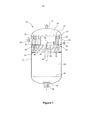
APARELHO DE TRATAMENTO DE FLUIDO, MÉTODO PARA TRATAR UM FLUIDO, E, ARRANJO DE BOCAL. Um aparelho de tratamento de fluido (10) compreende um vaso de fluido (12) tendo primeira e segunda câmaras de fluido (14, 16). Um entrada do fluido (26) é provida para dispensar um fluido a ser tratado para a primeira câmara de fluido (14). Pelo menos um conjunto de bocal (34) é arranjado entre as primeira e a segunda câmaras (14, 16) para prover comunicação fluida da primeira câmara de fluido (14) para a segunda câmara de fluido (16), onde o mencionado conjunto de bocal (34) é adaptado para facilitar a mistura de um gás com o mencionado fluido.FLUID TREATMENT APPLIANCE, METHOD FOR TREATING A FLUID, AND, NOZZLE ARRANGEMENT. A fluid treatment apparatus (10) comprises a fluid vessel (12) having first and second fluid chambers (14, 16). A fluid inlet (26) is provided to dispense a fluid to be treated for the first fluid chamber (14). At least one nozzle assembly (34) is arranged between the first and second chambers (14, 16) to provide fluid communication from the first fluid chamber (14) to the second fluid chamber (16), where said set of nozzle (34) is adapted to facilitate mixing of a gas with said fluid.
Description
[001] A presente invenção se refere a um aparelho de tratamento de fluido e, em particular, mas não exclusivamente, a um aparelho para tratamento de água produzida a partir de uma formação subterrânea portadora de hidrocarbonetos. A presente invenção também se refere a um método de tratamento de um fluido.[001] The present invention relates to a fluid treatment apparatus and, in particular, but not exclusively, to an apparatus for treating water produced from an underground formation carrying hydrocarbons. The present invention also relates to a method of treating a fluid.
[002] Os fluidos produzidos a partir de reservatórios subterrâneos são geralmente uma mistura de óleo, água, gás, normalmente com uma quantidade de areia. Nos estágios iniciais de produção, os fluidos podem ser “secos”, ou seja, contendo pouca ou nenhuma água, mas à medida que a produção continua é normal que um volume maior de água seja produzido. Em campos maduros, a proporção de água nos fluidos produzidos pode chegar a 90% e, possivelmente, em torno de 95%. Reservatórios nem sempre produzem grandes volumes de areia, mas quando o fazem, a produção de areia geralmente aumenta com o aumento da produção de água. A água produzida a partir do reservatório é denominada “água produzida”.[002] Fluids produced from underground reservoirs are generally a mixture of oil, water, gas, usually with an amount of sand. In the early stages of production, fluids can be “dry”, that is, containing little or no water, but as production continues it is normal for a larger volume of water to be produced. In mature fields, the proportion of water in the fluids produced can reach 90% and possibly around 95%. Reservoirs do not always produce large volumes of sand, but when they do, sand production generally increases with increasing water production. The water produced from the reservoir is called “produced water”.
[003] A água produzida pode ser injetada de volta para a formação ou pode ser descarregada no meio ambiente, por exemplo, em áreas de produção fora da costa, a água pode ser descarregada no mar. Entretanto, a água produzida deve ser cuidadosamente tratada, de modo a remover substancialmente todos os vestígios de óleo e gás, antes de ser descarregada no meio ambiente, de modo a atender as normas ambientais extremamente rigorosas.[003] The produced water can be injected back into the formation or it can be discharged into the environment, for example, in production areas off the coast, the water can be discharged into the sea. However, the water produced must be carefully treated, in order to remove substantially all traces of oil and gas, before being discharged into the environment, in order to meet extremely strict environmental standards.
[004] Nas operações convencionais de produção, o fluido produzido a partir do reservatório é inicialmente tratado para separar o óleo e gás comercializáveis da água e areia não comercializáveis. Entretanto, a água separada normalmente ainda contém quantidades inaceitáveis de óleo e gás e, como tal, é normalmente submetida a um tratamento secundário para reduzir ainda mais a concentração de hidrocarbonetos a níveis aceitáveis para descarga no meio ambiente ou injeção de volta para a formação.[004] In conventional production operations, the fluid produced from the reservoir is initially treated to separate the marketable oil and gas from the non-marketable water and sand. However, the separated water normally still contains unacceptable amounts of oil and gas and, as such, is normally subjected to secondary treatment to further reduce the concentration of hydrocarbons to acceptable levels for discharge into the environment or injection back into the formation.
[005] Um processo conhecido como “flotação” é comumente usado para auxiliar na remoção de óleo e outros contaminantes da água. O princípio da flotação é que bolhas de gás são introduzidas (por exemplo, flotação por gás induzido) ou são estabelecidas em (por exemplo, flotação por gás dissolvido) um vaso contendo uma água contaminada, no qual as bolhas vão, em um maior ou menor grau, se acoplar aos contaminantes, como gotículas de óleo, e arrastá-los para a superfície da água, deixando a maior parte da água esgotada de contaminantes e as camadas superiores da água enriquecidas com contaminantes. Nas explicações subsequentes, cada volume de água ao qual são adicionadas ou criadas bolhas de gás para separar contaminantes pode ser referido como uma “célula” ou “célula de flotação”.[005] A process known as "flotation" is commonly used to assist in the removal of oil and other contaminants from water. The flotation principle is that gas bubbles are introduced (for example, induced gas flotation) or are established in (for example, dissolved gas flotation) a vessel containing contaminated water, in which the bubbles go, in a larger or to a lesser extent, attaching to contaminants, such as oil droplets, and dragging them to the surface of the water, leaving most of the water depleted of contaminants and the upper layers of water enriched with contaminants. In subsequent explanations, each volume of water to which gas bubbles are added or created to separate contaminants can be referred to as a "cell" or "flotation cell".
[006] A flotação é operada, normalmente, como um processo contínuo, onde há uma entrada contínua de água contaminada na célula e uma saída contínua de água enriquecida em contaminantes arrastados das camadas superficiais da célula e uma saída contínua da água esgotada em contaminantes da célula, a uma taxa, de modo a manter um nível essencialmente constante no reservatório.[006] Flotation is normally operated as a continuous process, where there is a continuous inflow of contaminated water into the cell and a continuous outflow of water enriched in contaminants dragged from the surface layers of the cell and a continuous outflow of water depleted in contaminants from cell, at a rate, in order to maintain an essentially constant level in the reservoir.
[007] É comum que os contaminantes flutuados para a superfície da água sejam retidos em uma espuma formada naturalmente quando os contaminantes estão presentes nas concentrações mais altas encontradas na superfície da água, ou com o auxílio de produtos químicos que são adicionados ao líquido de entrada. Contaminantes flutuantes, por exemplo, gotículas de óleo, podem não precisar ser espumados para mantê-los na superfície.[007] It is common for contaminants floated to the water surface to be retained in a naturally formed foam when the contaminants are present in the highest concentrations found on the water surface, or with the aid of chemicals that are added to the inlet liquid. . Floating contaminants, for example, oil droplets, may not need to be foamed to keep them on the surface.
[008] Os contaminantes na superfície da água podem ser removidos por uma variedade de meios, os dois mais comuns sendo escoadouros colocados ligeiramente abaixo da superfície da água de modo que a camada superficial enriquecida em contaminantes escoe, preferencialmente, sobre eles, ou pás que varrem a camada superficial enriquecida em contaminantes sobre um escoadouro colocado, normalmente, ligeiramente acima da superfície da água. Também são conhecidos inúmeros projetos de dispositivos de escumadeira flutuante que têm a vantagem de poderem tolerar uma variação mais ampla no nível de líquido operacional do que qualquer dos métodos de escoadouro fixo mencionados anteriormente podem acomodar.[008] Contaminants on the surface of the water can be removed by a variety of means, the two most common being drains placed slightly below the surface of the water so that the surface layer enriched with contaminants flows, preferentially, over them, or shovels that sweep the contaminated-enriched surface layer over a drain, normally placed slightly above the water surface. Numerous designs of floating skimmer devices are also known that have the advantage of being able to tolerate a wider variation in the level of operating liquid than any of the aforementioned fixed drain methods can accommodate.
[009] Nos métodos de Flotação por Gás Induzido (IGF), bolhas de gás são, tipicamente, adicionadas à água contaminada por edutores ou misturadores mecânicos. Uma célula de IGF deve ser misturada para colocar as bolhas de gás em contato íntimo com os contaminantes, como gotículas de óleo, de modo que estes possam ser separados por elas, mas essa mistura tem os efeitos colaterais de tornar mais difícil para as bolhas subirem à superfície, e provocar variação no tempo de residência das parcelas de água no interior da célula. Embora o tempo médio de residência na célula possa ser determinado pelo volume da célula e vazão da água, a mistura pode significar que algumas parcelas de água passam através da célula por um tempo muito mais curto do que o necessário para uma boa separação, e, inversamente, algumas parcelas de água podem permanecer na célula por muito mais tempo do que o tempo médio de residência.[009] In Induced Gas Flotation (IGF) methods, gas bubbles are typically added to contaminated water by eductors or mechanical mixers. An IGF cell must be mixed to bring the gas bubbles in close contact with the contaminants, such as oil droplets, so that they can be separated by them, but this mixture has the side effects of making it more difficult for the bubbles to rise. to the surface, and cause variation in the residence time of the water parcels inside the cell. Although the average residence time in the cell can be determined by the cell volume and water flow, mixing can mean that some portions of water pass through the cell for a much shorter time than is necessary for good separation, and, conversely, some plots of water may remain in the cell for much longer than the average residence time.
[0010] A necessidade de se misturar na célula para colocar em contato as bolhas de gás e os contaminantes reduz a eficiência de separação na célula. Por esta razão os vasos de IGF são normalmente vasos horizontais que contêm uma pluralidade de células de IGF em série, tipicamente quatro, de modo que a eficiência global da separação seja aumentada. Exemplos de sistemas de IGF conhecidos deste tipo são mostrados nas USA 4.564.457, USA 2006/0.213.840, USA 3.972.815, USA 3.647.069 e USA 5.348.648.[0010] The need to mix in the cell to put gas bubbles and contaminants in contact reduces the separation efficiency in the cell. For this reason, IGF vessels are usually horizontal vessels that contain a plurality of IGF cells in series, typically four, so that the overall efficiency of the separation is increased. Examples of known IGF systems of this type are shown in USA 4,564,457, USA 2006 / 0,213,840, USA 3,972,815, USA 3,647,069 and USA 5,348,648.
[0011] No entanto, em algumas aplicações, são conhecidas unidades de células de flotação de estágio único verticais, que têm uma única célula de IGF que tem, tipicamente, um volume de célula e, por conseguinte, tempo de residência, um pouco maior do que o que seria encontrado nas quatro células de uma unidade de IGF horizontal típica. Exemplos destes arranjos de IGF são mostrados no WO 2004/112.936 e USA 5.011. 597.[0011] However, in some applications, vertical single-stage flotation cell units are known, which have a single IGF cell that typically has a slightly larger cell volume and therefore residence time than what would be found in the four cells of a typical horizontal IGF unit. Examples of these IGF arrangements are shown in WO 2004 / 112,936 and USA 5,011. 597.
[0012] Deve ser entendido que uma unidade de IGF requer que o fluido permaneça no vaso por um período suficiente para permitir a flotação do óleo e a separação do gás Entretanto, o aumento do tempo de residência reduzirá diretamente a taxa máxima de tratamento de fluido que pode ser obtida. Pode ser possível resolver este problema pelo aumento do tamanho da unidade de IGF, mas isto não é desejado, devido ao espaço disponível limitado em ambientes de produção convencionais.[0012] It should be understood that an IGF unit requires the fluid to remain in the vessel for a sufficient period to allow oil flotation and gas separation. However, increasing the residence time will directly reduce the maximum fluid treatment rate. that can be obtained. It may be possible to solve this problem by increasing the size of the IGF unit, but this is not desired, due to the limited available space in conventional production environments.
[0013] É desejável reduzir o espaço ocupado e o peso do equipamento instalado sobre plataformas marinhas e, por esta razão, têm sido propostas, na técnica, unidades de flotação compactas para o tratamento de água produzida com mínima área ocupada pela instalação. Por exemplo, com referência à técnica anterior, a WO 02/41.965 apresenta um vaso arranjado verticalmente, que recebe fluido sendo tratado através de uma entrada de fluido arranjada tangencialmente. O arranjo da entrada de fluido desta maneira estabelece a rotação do fluido no vaso, o que é suposto ajudar a coalescência de óleo e bolhas de gás e a flotação para a superfície. O vaso pode incorporar uma palheta guia espiralada para realçar a rotação do fluido.[0013] It is desirable to reduce the space occupied and the weight of the equipment installed on marine platforms and, for this reason, compact flotation units have been proposed in the art for the treatment of water produced with a minimum area occupied by the installation. For example, with reference to the prior art, WO 02 / 41.965 discloses a vertically arranged vessel, which receives fluid being treated through a tangentially arranged fluid inlet. The arrangement of the fluid inlet in this way establishes the rotation of the fluid in the vessel, which is supposed to aid the coalescence of oil and gas bubbles and flotation to the surface. The vessel may incorporate a spiral guide vane to enhance the rotation of the fluid.
[0014] Na WO 02/41.965 o vaso é operado a uma pressão baixa para permitir que gás dissolvido evolua da fase aquosa e crie bolhas de gás na zona adjacente à entrada de fluido para imitar o efeito de unidades de IGF. No entanto, caso um volume insuficiente de gás esteja presente no fluido, então, gás adicional pode ser adicionado ao fluido.[0014] In WO 02 / 41.965 the vessel is operated at a low pressure to allow dissolved gas to evolve from the aqueous phase and create gas bubbles in the area adjacent to the fluid inlet to mimic the effect of IGF units. However, if an insufficient volume of gas is present in the fluid, then additional gas can be added to the fluid.
[0015] A EP 1.400.492 também apresenta uma unidade de flotação compacta que compreende um vaso arranjado verticalmente, com uma ou mais entradas de fluido tangenciais para encorajar a rotação de fluido. Na EP 1.400.492, o vaso também inclui entradas de fluido/gás espargido arranjadas tangencialmente. Estas entradas comunicam água gaseificada para o vaso.[0015] EP 1,400,492 also features a compact flotation unit that comprises a vertically arranged vessel, with one or more tangential fluid inlets to encourage fluid rotation. In EP 1,400,492, the vessel also includes fluid / sparged gas inlets arranged tangentially. These inlets communicate carbonated water to the vessel.
[0016] Outras técnicas para o tratamento de fluidos pelo uso de bolhas de gás incluem técnicas de flotação em cascata, na qual o fluido sendo tratado é passado através de edutores para recipientes, em forma de cascata. Exemplos destas técnicas são apresentadas nas US 1.311.919, US, 1.380.665 e US 4.406.782.[0016] Other techniques for the treatment of fluids by the use of gas bubbles include cascade flotation techniques, in which the fluid being treated is passed through eductors to containers, in the form of a cascade. Examples of these techniques are presented in US 1,311,919, US, 1,380,665 and US 4,406,782.
[0017] A US 4.986.903 apresenta um aparelho de flotação para separar óleo de água. O aparelho apresentado inclui câmaras de gaseificação e de degaseificação separadas. Água gaseificada é introduzida na câmara de gaseificação via um edutor de gás. A recirculação do fluido a ser gaseificado é possível entre a câmara de degaseificação e a câmara de gaseificação através da linha de recirculação 70 e o edutor de gás 40.[0017] US 4,986,903 features a flotation device for separating oil from water. The apparatus shown includes separate gasification and degassing chambers. Carbonated water is introduced into the gasification chamber via a gas eductor. The recirculation of the fluid to be aerated is possible between the degassing chamber and the aeration chamber through the
[0018] Entre os objetivos da presente invenção está evitar ou atenuar um ou mais problemas da técnica anterior.[0018] Among the objectives of the present invention is to avoid or mitigate one or more problems of the prior art.
[0019] De acordo com um primeiro aspecto da presente invenção é provido um aparelho de tratamento de fluido compreendendo: um vaso de fluido; primeira e segunda câmaras de fluido definidas no interior do vaso de fluido; uma entrada de fluido para dispensar um fluido a ser tratado para a primeira câmara de fluido; e pelo menos um conjunto de bocal para prover comunicação fluida da primeira câmara de fluido para a segunda câmara de fluido, onde o mencionado conjunto de bocal é adaptado para facilitar a mistura de um gás com o mencionado fluido.[0019] According to a first aspect of the present invention, a fluid treatment apparatus is provided comprising: a fluid vessel; first and second fluid chambers defined within the fluid vessel; a fluid inlet for dispensing a fluid to be treated for the first fluid chamber; and at least one nozzle assembly to provide fluid communication from the first fluid chamber to the second fluid chamber, where said nozzle assembly is adapted to facilitate mixing of a gas with said fluid.
[0020] O pelo menos um conjunto de bocal pode facilitar o carreamento de um gás para o mencionado fluido. Alternativa, ou adicionalmente, o pelo menos um conjunto de bocal pode facilitar a injeção, mistura ou dispensação de um gás para o mencionado fluido. Entretanto, para a brevidade do presente sumário da invenção, o conceito geral de mistura de gás, ou dispensação de um gás para o fluido sendo tratada será referido, de modo geral, como carreamento.[0020] The at least one nozzle assembly can facilitate the carrying of a gas to the said fluid. Alternatively, or in addition, the at least one nozzle assembly can facilitate the injection, mixing or dispensing of a gas into said fluid. However, for the sake of brevity of the present summary of the invention, the general concept of gas mixing, or dispensing a gas into the fluid being treated will generally be referred to as carrying.
[0021] O aparelho pode ser adaptado para tratar um fluido contendo vários componentes, cujos componentes podem compreender qualquer um ou uma combinação de líquidos, gases e sólidos. Por exemplo, o fluido pode compreender uma mistura de água/óleo, mistura de água/óleo/gás, ou similar.[0021] The device can be adapted to treat a fluid containing several components, the components of which can comprise any one or a combination of liquids, gases and solids. For example, the fluid may comprise a water / oil mixture, water / oil / gas mixture, or the like.
[0022] A primeira câmara de fluido pode ser adaptada para receber o fluido a ser tratado e distribuir este fluido para a segunda câmara de fluido, com o gás carreado para ser tratado na mesma. A primeira câmara de fluido pode, por conseguinte, definir uma câmara de distribuição e a segunda câmara pode definir uma câmara de tratamento.[0022] The first fluid chamber can be adapted to receive the fluid to be treated and distribute this fluid to the second fluid chamber, with the gas carried to be treated therein. The first fluid chamber can therefore define a distribution chamber and the second chamber can define a treatment chamber.
[0023] A segunda câmara de fluido pode ser adaptada para acomodar um tratamento de separação de fluido na mesma. O tratamento de separação pode ser adaptado para efetuar a separação dos componentes do fluido, como componentes de diferentes densidades, químicas, fases, ou similares. Vantajosamente, o gás carreado no líquido que entra na segunda câmara pode realçar a separação de fluido. O tratamento de separação pode compreender um tratamento de separação por flotação.[0023] The second fluid chamber can be adapted to accommodate a fluid separation treatment in it. The separation treatment can be adapted to separate the components of the fluid, such as components of different densities, chemicals, phases, or the like. Advantageously, the gas carried in the liquid entering the second chamber can enhance fluid separation. The separation treatment can comprise a flotation separation treatment.
[0024] Em um modo de realização, a segunda câmara de fluido pode ser adaptada para acomodar um tratamento de separação para efetuar a separação de óleo mineral e, opcionalmente, gás de água, como a água produzida proveniente de um reservatório de hidrocarboneto subterrâneo. Nesse arranjo o carreamento de gás para o fluido, comunicado proveniente da primeira câmara de fluido pode ajudar a flotação do óleo. O óleo pode ser escumado ou de outra maneira coletado da superfície da água no interior da segunda câmara de fluido. Adicionalmente, o gás liberado da água pode ser coletado.[0024] In one embodiment, the second fluid chamber can be adapted to accommodate a separation treatment to effect the separation of mineral oil and, optionally, water gas, such as water produced from an underground hydrocarbon reservoir. In this arrangement, the carrying of gas to the fluid, communicated from the first fluid chamber, can help oil flotation. The oil can be skimmed or otherwise collected from the water surface inside the second fluid chamber. Additionally, the gas released from the water can be collected.
[0025] Vantajosamente, a provisão do pelo menos um conjunto de bocal para facilitar o carreamento de gás para o fluido sendo tratado pode eliminar a necessidade de provisão de equipamento de instalação externo, como gaseificadores, misturadores, bombas, compressores e similares, associados aos arranjos da técnica anterior. No entanto, em modos de realização da presente invenção pode ser desejável utilizar estes equipamentos externos ou adicionais. Além disso, o pelo menos um conjunto de bocal pode ser adaptado para comunicar fluido que já tenha sido misturado com um gás para a segunda câmara de fluido. Desse modo, o tempo de residência do fluido na segunda câmara pode ser utilizado substancialmente inteiramente para o tratamento do fluido, como a separação dos componentes do fluido. Por conseguinte, isto difere dos arranjos da técnica anterior nos quais o tempo de residência também deve acomodar mistura suficiente de gás/fluido.[0025] Advantageously, the provision of at least one nozzle assembly to facilitate the carrying of gas into the fluid being treated can eliminate the need for the provision of external installation equipment, such as gasifiers, mixers, pumps, compressors and the like, associated with prior art arrangements. However, in embodiments of the present invention it may be desirable to use these external or additional equipment. In addition, the at least one nozzle assembly can be adapted to communicate fluid that has already been mixed with a gas to the second fluid chamber. In this way, the residence time of the fluid in the second chamber can be used substantially entirely for the treatment of the fluid, such as the separation of the fluid components. Therefore, this differs from prior art arrangements in which the residence time must also accommodate sufficient gas / fluid mix.
[0026] O vaso de fluido pode ser arranjado verticalmente. Este arranjo pode ajudar a minimizar a área ocupada pelo aparelho de tratamento de fluido, o que é vantajoso, principalmente em aplicações marinhas. Alternativamente, o vaso de fluido pode ser arranjado horizontalmente. Ainda alternativamente, o vaso de fluido pode ser arranjado para se inclinar.[0026] The fluid vessel can be arranged vertically. This arrangement can help to minimize the area occupied by the fluid treatment apparatus, which is advantageous, especially in marine applications. Alternatively, the fluid vessel can be arranged horizontally. Alternatively, the fluid vessel may be arranged to tilt.
[0027] As primeira e a segunda câmaras de fluido podem ser arranjadas para serem adjacentes uma à outra, no interior do vaso. Alternativamente, as primeira e a segunda câmaras podem ser arranjadas separadamente, no vaso. As primeira e a segunda câmaras de fluido podem ser arranjadas verticalmente no interior do vaso. Ou seja, uma câmara pode ser, pelo menos parcialmente, arranjada acima da outra câmara. Em um modo de realização, a primeira câmara pode ser, pelo menos parcialmente, arranjada acima de uma porção da segunda câmara. Isso pode facilitar uma alimentação por gravidade do fluido entre as câmaras.[0027] The first and second fluid chambers can be arranged to be adjacent to each other, inside the vessel. Alternatively, the first and second chambers can be arranged separately, in the vessel. The first and second fluid chambers can be arranged vertically inside the vessel. That is, one chamber can be, at least partially, arranged above the other chamber. In one embodiment, the first chamber can be, at least partially, arranged above a portion of the second chamber. This can facilitate gravity feeding of the fluid between the chambers.
[0028] Alternativa, ou adicionalmente, as primeira e a segunda câmaras podem ser arranjadas horizontalmente no interior do vaso. Ou seja, uma câmara pode ser arranjada, pelo menos parcialmente, ao lado da outra câmara.[0028] Alternatively, or in addition, the first and second chambers can be arranged horizontally inside the vessel. That is, one chamber can be arranged, at least partially, next to the other chamber.
[0029] O aparelho pode compreender uma divisória adaptada para, pelo menos parcialmente, separar as primeira e a segunda câmaras de fluido. A divisória pode dividir o vaso pelo menos nas primeira e segunda câmaras de fluido. A divisória pode compreender uma placa ou similar, e pode ser de qualquer formato adequado, como, geralmente, circular, anular, quadrada, retangular ou similar. A divisória pode ser fixada a uma superfície interna do vaso, por exemplo, por soldagem, uma conexão flangeada, parafusos, encaixe por interferência ou similar, ou qualquer combinação adequada dos mesmos. A divisória pode ser formada como um componente único, ou pode ser formada por vários componentes.[0029] The apparatus may comprise a partition adapted to, at least partially, separate the first and second fluid chambers. The partition can divide the vessel into at least the first and second fluid chambers. The partition may comprise a plate or the like, and may be of any suitable shape, such as, generally, circular, annular, square, rectangular or similar. The partition can be fixed to an internal surface of the vessel, for example, by welding, a flanged connection, screws, interference fit or similar, or any suitable combination thereof. The partition can be formed as a single component, or it can be formed by several components.
[0030] A divisória pode definir uma porção de parede ou limite de uma ou de ambas as primeira e segunda câmaras. A divisória pode definir uma base de uma ou de ambas as câmaras. A divisória pode definir uma região superior ou teto de uma ou de ambas as câmaras. Em um modo de realização da presente invenção a divisória pode definir uma base da primeira câmara e um teto da segunda câmara.[0030] The partition can define a portion of the wall or boundary of one or both of the first and second chambers. The partition can define a base for one or both chambers. The partition can define an upper region or ceiling for one or both chambers. In an embodiment of the present invention the partition can define a base of the first chamber and a ceiling of the second chamber.
[0031 ] O pelo menos um conjunto de bocal pode ser adaptado para se estender através da divisória. O pelo menos um conjunto de bocal pode ser fixado à divisória de modo que esta proveja suporte para o pelo menos um conjunto de bocal.[0031] The at least one nozzle assembly can be adapted to extend through the partition. The at least one nozzle assembly can be attached to the partition so that it provides support for the at least one nozzle assembly.
[0032] O pelo menos um conjunto de bocal pode compreender um primeiro conduto de fluido definindo uma porta de fluido adaptada para permitir comunicação de fluido a ser tratado proveniente da primeira câmara de fluido para o primeiro conduto de fluido. A porta de fluido pode ser provida na região de base da primeira câmara de fluido. Alternativamente, a porta de fluido pode ser provida em uma localização elevada em relação a uma região de base da primeira câmara de fluido. Neste arranjo, a localização elevada da porta de fluido pode permitir que o conjunto de bocal seja operacional apenas quando um gradiente predefinido de fluido a ser tratado esteja presente na primeira câmara de fluido. Esse arranjo pode ajudar a permitir a obtenção de uma velocidade e faixa de fluxo preferenciais entre as primeira e segunda câmaras. O primeiro conduto de fluido pode ficar totalmente contido no vaso. Como alternativa, pelo menos uma porção do primeiro conduto de fluido pode se estender externamente ao vaso.[0032] The at least one nozzle assembly may comprise a first fluid conduit defining a fluid port adapted to allow communication of fluid to be treated from the first fluid chamber to the first fluid conduit. The fluid port can be provided in the base region of the first fluid chamber. Alternatively, the fluid port can be provided at an elevated location relative to a base region of the first fluid chamber. In this arrangement, the elevated location of the fluid port can allow the nozzle assembly to be operational only when a predefined gradient of fluid to be treated is present in the first fluid chamber. This arrangement can help to achieve a preferred speed and flow range between the first and second chambers. The first fluid conduit can be completely contained in the vessel. Alternatively, at least a portion of the first fluid conduit may extend outside the vessel.
[0033] O pelo menos um conjunto de bocal pode compreender um segundo conduto de fluido adaptado para permitir comunicação fluida de um gás proveniente de uma fonte de gás para uma porção do conjunto de bocal. Desta maneira, o gás proveniente da fonte de gás pode ser carreado para o fluido sendo tratado.[0033] The at least one nozzle assembly may comprise a second fluid conduit adapted to allow fluid communication from a gas from a gas source to a portion of the nozzle assembly. In this way, the gas from the gas source can be carried to the fluid being treated.
[0034] A fonte de gás pode compreender gás contido no vaso, e pode compreender gás contido em uma ou em ambas as primeira e segunda câmaras de fluido. Nesse arranjo o segundo conduto de fluido pode definir uma porta de fluido aberta para uma região carregada com gás de uma ou de ambas as primeira e segunda câmaras de fluido. O gás pode compreender gás liberado do fluido sendo tratado. Alternativamente, o gás pode compreender gás provido por uma fonte externa.[0034] The gas source may comprise gas contained in the vessel, and may comprise gas contained in one or both of the first and second fluid chambers. In this arrangement the second fluid conduit can define an open fluid port for a gas charged region of one or both of the first and second fluid chambers. The gas may comprise gas released from the fluid being treated. Alternatively, the gas may comprise gas provided by an external source.
[0035] O segundo conduto de fluido pode ser acoplado diretamente a uma fonte de gás externa.[0035] The second fluid conduit can be coupled directly to an external gas source.
[0036] O segundo conduto de fluido pode ficar totalmente contido no vaso. Alternativamente, pelo menos uma parte do segundo conduto de fluido pode se estender externamente ao vaso.[0036] The second fluid conduit can be completely contained in the vessel. Alternatively, at least a portion of the second fluid conduit may extend outside the vessel.
[0037] O pelo menos um conjunto de bocal pode compreender um tubo de descarga em comunicação fluida com um ou ambos dos primeiro e segundo condutos de fluido. Pelo menos uma porção do tubo de descarga pode facilitar a mistura ou mescla de fluido dispensado através do primeiro conduto de fluido com gás dispensado via segundo conduto de fluido. Nesse arranjo, turbulência e mistura no tubo de descarga podem configurar o gás em pequenas bolhas e fazer com que estas bolhas se misturem intimamente com o fluido proveniente da primeira câmara. Consequentemente, o conjunto de bocal pode dispensar para a segunda câmara um fluido que contém uma distribuição favorável de bolhas de gás para tratamento de fluido subsequente na segunda câmara.[0037] The at least one nozzle assembly may comprise a discharge tube in fluid communication with one or both of the first and second fluid conduits. At least a portion of the discharge tube can facilitate mixing or mixing of dispensed fluid through the first fluid conduit with gas dispensed via the second fluid conduit. In this arrangement, turbulence and mixing in the discharge tube can configure the gas in small bubbles and cause these bubbles to mix intimately with the fluid coming from the first chamber. Consequently, the nozzle assembly can dispense to the second chamber a fluid that contains a favorable distribution of gas bubbles for subsequent fluid treatment in the second chamber.
[0038] O tubo de descarga pode definir uma abertura de saída de fluido para a segunda câmara de fluido para permitir que gás e a mistura de fluidos possam ser descarregados para a mencionada segunda câmara. A saída de fluido do tubo de descarga pode ser adaptada para ser, pelo menos parcialmente, submersa no fluido sendo tratado no interior da segunda câmara de fluido.[0038] The discharge tube can define a fluid outlet opening for the second fluid chamber to allow gas and the mixture of fluids to be discharged into said second chamber. The fluid outlet of the discharge tube can be adapted to be, at least partially, submerged in the fluid being treated inside the second fluid chamber.
[0039] O tubo de descarga pode ser arranjado para descarregar fluido para qualquer região da segunda câmara. Em um modo de realização, o tubo de descarga pode ser arranjado para descarregar fluido para uma região externa da segunda câmara.[0039] The discharge tube can be arranged to discharge fluid to any region of the second chamber. In one embodiment, the discharge tube can be arranged to discharge fluid to an external region of the second chamber.
[0040] O tubo de descarga pode ser orientado para permitir que fluido e a mistura de gás sejam descarregados para a segunda câmara em uma direção predeterminada. Esse arranjo pode ajudar a estabelecer um movimento de fluido preferido na segunda câmara de fluido. Em um modo de realização, o tubo de descarga pode ser arranjado para estabelecer fluxo rotativo na segunda câmara. O fluxo rotativo pode ser estabelecido em relação a um eixo central da segunda câmara. O fluxo rotativo na segunda câmara de fluido pode ajudar o tratamento de fluido na mesma. Por exemplo, o fluxo rotativo pode ajudar a movimentação preferencial de bolhas de gás no fluido sendo tratado, o movimento preferencial dos componentes do fluido para regiões de descarga da segunda câmara, e similares. O fluxo rotativo pode impedir mistura à frente do líquido tratado em direção a uma saída (ou seja, descarga prematura do fluido sendo tratado), e pode modificar a distribuição do tempo de residência.[0040] The discharge tube can be oriented to allow fluid and gas mixture to be discharged to the second chamber in a predetermined direction. This arrangement can help to establish a preferred fluid movement in the second fluid chamber. In one embodiment, the discharge tube can be arranged to establish rotational flow in the second chamber. The rotational flow can be established in relation to a central axis of the second chamber. The rotational flow in the second fluid chamber can assist with fluid treatment therein. For example, the rotary flow can assist the preferred movement of gas bubbles in the fluid being treated, the preferred movement of the fluid components to discharge regions of the second chamber, and the like. The rotating flow can prevent mixing in front of the treated liquid towards an outlet (ie, premature discharge of the fluid being treated), and can modify the residence time distribution.
[0041] O tubo de descarga pode ser arranjado obliquamente (ou seja, não paralelo) em relação a um eixo central da segunda câmara. O tubo de descarga pode ser arranjado obliquamente para descarregar fluido para uma região externa da segunda câmara para iniciar, vantajosamente, o fluxo rotativo na mencionada segunda câmara. O tubo de descarga pode ser adaptado para descarregar fluido com uma primeira componente de velocidade paralela a um eixo central da segunda câmara de fluido, e uma segunda componente de velocidade perpendicular ao eixo central (ou seja, tangencial a um círculo com uma origem coincidindo com o eixo central do vaso).[0041] The discharge tube can be arranged obliquely (ie, not parallel) in relation to a central axis of the second chamber. The discharge tube can be arranged obliquely to discharge fluid to an external region of the second chamber to advantageously initiate the rotary flow in said second chamber. The discharge tube can be adapted to discharge fluid with a first velocity component parallel to a central axis of the second fluid chamber, and a second velocity component perpendicular to the central axis (that is, tangential to a circle with an origin coinciding with the central axis of the vessel).
[0042] O aparelho pode compreender uma pluralidade de conjuntos de bocal. Pelo menos um da pluralidade de conjuntos de bocal pode ser similar ao pelo menos um conjunto de bocal descrito acima.[0042] The apparatus may comprise a plurality of nozzle assemblies. At least one of the plurality of nozzle assemblies may be similar to the at least one nozzle assembly described above.
[0043] Os conjuntos de bocal podem ser arranjados em uma configuração anular em relação à primeira câmara de fluido. No entanto, outras configurações podem ser utilizadas. Por exemplo, os conjuntos de bocal podem ser arranjados para, de modo geral, se conformar com a forma periférica externa do vaso, que pode ser diferente da circular.[0043] The nozzle assemblies can be arranged in an annular configuration in relation to the first fluid chamber. However, other settings can be used. For example, nozzle assemblies can be arranged to generally conform to the outer peripheral shape of the vessel, which may differ from the circular.
[0044] Cada conjunto de bocal pode ser adaptado para ser operacional substancialmente na mesma faixa de gradiente de fluido na primeira câmara de fluido. Por exemplo, cada conjunto de bocal pode compreender uma porta de fluido adaptada para permitir comunicação com o fluido contido na primeira câmara de fluido, onde as portas de fluido podem ser arranjadas substancialmente na mesma altura em relação a uma região de base da primeira câmara de fluido. Consequentemente, quando o gradiente, ou seja, o nível de fluido, no interior da primeira câmara de fluido cair abaixo do nível das portas de fluido, todos os conjuntos de bocal se tornarão ineficazes, até que um gradiente suficiente seja reestabelecido.[0044] Each nozzle assembly can be adapted to be operational in substantially the same fluid gradient range in the first fluid chamber. For example, each nozzle assembly may comprise a fluid port adapted to allow communication with the fluid contained in the first fluid chamber, where the fluid ports can be arranged at substantially the same height with respect to a base region of the first fluid chamber. fluid. Consequently, when the gradient, that is, the fluid level, inside the first fluid chamber falls below the level of the fluid ports, all nozzle assemblies will become ineffective, until a sufficient gradient is reestablished.
[0045] Alternativamente, pelo menos um da pluralidade de conjuntos de bocal pode ser adaptado para ser operacional a um gradiente de fluido diferente no interior da primeira câmara de fluido, diferente do pelo menos outro da pluralidade de conjuntos de bocal. Por exemplo, pelo menos dois dos conjuntos de bocal podem compreender as respectivas portas de fluido adaptadas para permitir comunicação com fluido contido no interior da primeira câmara de fluido, onde as portas de fluido podem ser arranjadas nas respectivas alturas diferentes em relação a uma região de base da primeira câmara de fluido. Consequentemente, neste arranjo, caso o gradiente de fluido na primeira câmara de fluido começar a cair, por exemplo, como resultado de uma vazão de fluxo reduzida através da entrada, os conjuntos de bocal se tornarão seqüencialmente ineficazes de acordo com as alturas das respectivas portas de fluido. Esse arranjo pode, por conseguinte, ser utilizado para manter uma faixa de velocidade preferida do fluido que entra na segunda câmara de fluido através dos conjuntos de bocal. A faixa de velocidade preferida pode ser selecionada de acordo com o fluxo necessário na segunda câmara de fluido. Neste arranjo, a provisão de um grau de controle sobre a faixa de velocidade pode ajudar a manter um padrão de fluxo preferencial (por exemplo, rotativo) na segunda câmara, reduzindo o efeito de variações no fluxo através da entrada da primeira câmara.Alternatively, at least one of the plurality of nozzle assemblies can be adapted to be operative to a different fluid gradient within the first fluid chamber, different from at least another of the plurality of nozzle assemblies. For example, at least two of the nozzle assemblies can comprise the respective fluid ports adapted to allow communication with fluid contained within the first fluid chamber, where the fluid ports can be arranged at the respective different heights with respect to a region of base of the first fluid chamber. Consequently, in this arrangement, if the fluid gradient in the first fluid chamber begins to fall, for example, as a result of a reduced flow rate through the inlet, the nozzle assemblies will become sequentially ineffective according to the heights of the respective ports. of fluid. Such an arrangement can therefore be used to maintain a preferred speed range of the fluid entering the second fluid chamber through the nozzle assemblies. The preferred speed range can be selected according to the flow required in the second fluid chamber. In this arrangement, the provision of a degree of control over the speed range can help maintain a preferred flow pattern (for example, rotary) in the second chamber, reducing the effect of variations in flow through the entrance of the first chamber.
[0046] A faixa de velocidade preferida também pode ser selecionada para manter a proporção de gás carreado com o fluido e a mistura entre eles, que ocorre no tubo de descarga dentro de valores pré-definidos.[0046] The preferred speed range can also be selected to maintain the proportion of gas carried with the fluid and the mixture between them, which occurs in the discharge tube within pre-defined values.
[0047] O aparelho pode compreender, opcionalmente um arranjo de defletor localizado no interior da segunda câmara. O arranjo de defletor pode ser configurado para minimizar mistura à frente de fluidos no interior da segunda câmara. O arranjo de defletor pode ser posicionado adjacente a uma superfície de parede da segunda câmara. O arranjo de defletor pode ser localizado na região do pelo menos um conjunto de bocal. O arranjo de defletor pode ser configurado para desviar fluido que incida sobre uma superfície de parede do conjunto de bocal.[0047] The apparatus may optionally comprise a deflector arrangement located inside the second chamber. The baffle arrangement can be configured to minimize mixing in front of fluids inside the second chamber. The baffle arrangement can be positioned adjacent to a wall surface of the second chamber. The baffle arrangement can be located in the region of at least one nozzle assembly. The deflector arrangement can be configured to deflect fluid that falls on a wall surface of the nozzle assembly.
[0048] O arranjo de defletor pode definir uma barreira contínua para o fluido na região de interesse. Alternativamente, o arranjo de defletor pode definir uma barreira descontínua. Isto pode permitir a liberação de partículas sólidas e similares que podem ser coletadas sobre o arranjo de defletor. O arranjo de defletor pode compreender orifícios ou similares. Um ou mais orifícios podem ser definidos em uma superfície do arranjo de defletor. Um ou mais orifícios podem ser definidos entre a superfície de borda do arranjo de defletor e a superfície de parede da segunda câmara.[0048] The deflector arrangement can define a continuous barrier for the fluid in the region of interest. Alternatively, the deflector arrangement can define a discontinuous barrier. This can allow the release of solid and similar particles that can be collected over the deflector arrangement. The baffle arrangement may comprise holes or the like. One or more holes can be defined on a surface of the baffle arrangement. One or more holes can be defined between the edge surface of the baffle arrangement and the wall surface of the second chamber.
[0049] O arranjo de defletor pode ser alinhado substancialmente perpendicular à superfície de parede da segunda câmara. O arranjo de defletor pode ser alinhado obliquamente em relação à superfície de parede da segunda câmara.[0049] The baffle arrangement can be aligned substantially perpendicular to the wall surface of the second chamber. The baffle arrangement can be aligned obliquely with respect to the wall surface of the second chamber.
[0050] Uma passagem de fluido pode ser provida entre as primeira e segunda câmaras para permitir comunicação fluida entre elas, de preferência em ambas as direções. A passagem de fluido pode ficar contida no interior do vaso. Alternativa, ou adicionalmente, uma porção da passagem de fluido pode se estender externamente ao vaso. A passagem de fluido pode ser adaptada para permitir comunicação fluida de um gás entre as primeira e a segunda câmaras. Em um modo de realização, a passagem de fluido pode ser adaptada para permitir comunicação fluida de um gás proveniente da segunda câmara de fluido para a primeira câmara de fluido. O gás pode compreender gás liberado de um fluido sendo tratado no interior da segunda câmara. Alternativa, ou adicionalmente, o gás pode compreender um gás suprido por uma fonte externa. A passagem de fluido pode, alternativa, ou adicionalmente, ser adaptada para comunicar um líquido ou sólidos, ou similar, entre as primeira e segunda câmaras de fluido.[0050] A fluid passage can be provided between the first and second chambers to allow fluid communication between them, preferably in both directions. The fluid passage can be contained within the vessel. Alternatively, or in addition, a portion of the fluid passage may extend externally to the vessel. The fluid passage can be adapted to allow fluid communication of a gas between the first and the second chambers. In one embodiment, the fluid passage can be adapted to allow fluid communication of a gas from the second fluid chamber to the first fluid chamber. The gas may comprise gas released from a fluid being treated within the second chamber. Alternatively, or in addition, the gas may comprise a gas supplied by an external source. The fluid passage can, alternatively, or additionally, be adapted to communicate a liquid or solids, or the like, between the first and second fluid chambers.
[0051] A passagem de fluido pode ser provida central ou excentricamente ao vaso. Pode ser provida uma passagem de fluido única, ou pode ser provida uma pluralidade de passagens de fluido. A passagem de fluido pode se estender através de uma divisória que separa as primeira e a segunda câmaras. A passagem de fluido pode ser definida por uma parede que se estende de uma superfície da divisória. Neste arranjo, a parede pode definir uma região anular com a superfície de parede interna da primeira câmara de fluido, onde a mencionada região anular é adaptada para receber fluido a ser tratado proveniente da entrada de fluido de vaso. O pelo menos um conjunto de bocal, pode ser posicionado na região anular.[0051] The passage of fluid can be provided centrally or eccentrically to the vessel. A single fluid passage can be provided, or a plurality of fluid passages can be provided. The fluid passage can extend through a partition that separates the first and second chambers. The fluid passage can be defined by a wall that extends from a surface of the partition. In this arrangement, the wall can define an annular region with the inner wall surface of the first fluid chamber, where said annular region is adapted to receive fluid to be treated from the vessel fluid inlet. The at least one nozzle assembly can be positioned in the annular region.
[0052] A primeira câmara de fluido pode compreender um conjunto distribuidor adaptado para receber fluido entrando na primeira câmara via entrada de fluido. O conjunto distribuidor pode ser adaptado para dissipar o momento do fluido de entrada. O conjunto distribuidor pode ser adaptado para distribuir o fluido em direção ao pelo menos um conjunto de bocal minimizando a turbulência. O conjunto distribuidor pode compreender uma estrutura em forma de caixa adaptada para receber fluido proveniente da entrada de fluido. A estrutura em forma de caixa pode compreender uma região perfurada, permitindo comunicação de fluido da mencionada estrutura.[0052] The first fluid chamber may comprise a distributor assembly adapted to receive fluid entering the first chamber via fluid inlet. The distributor assembly can be adapted to dissipate the moment of the inlet fluid. The dispensing assembly can be adapted to distribute the fluid towards at least one nozzle assembly minimizing turbulence. The dispensing assembly may comprise a box-shaped structure adapted to receive fluid from the fluid inlet. The box-like structure may comprise a perforated region, allowing fluid communication from said structure.
[0053] O aparelho pode compreender uma ou mais saídas de fluido para permitir a descarga de líquido tratado, ou seus componentes, do vaso. As saídas de fluido podem ser providas em uma ou em ambas as primeira e segunda câmaras de fluido. Em um modo de realização, o aparelho pode compreender uma primeira saída de fluido adaptada para permitir predominantemente a descarga de um primeiro componente de fluido, como um líquido, por exemplo, água. A primeira saída de fluido pode ser posicionada no interior da segunda câmara, e pode ser posicionada no interior de uma região inferior da segunda câmara.[0053] The device can comprise one or more fluid outlets to allow the discharge of treated liquid, or its components, from the vessel. The fluid outlets can be provided in one or both of the first and second fluid chambers. In one embodiment, the apparatus may comprise a first fluid outlet adapted to predominantly allow the discharge of a first fluid component, such as a liquid, for example, water. The first fluid outlet can be positioned inside the second chamber, and can be positioned inside a lower region of the second chamber.
[0054] O aparelho pode compreender, adicionalmente, uma segunda saída de fluido adaptada para permitir predominantemente a descarga de um segundo componente de fluido, como um líquido, por exemplo, óleo. A segunda saída de fluido pode ser posicionada no interior da segunda câmara de fluido, e a segunda saída de fluido pode ser posicionada no interior de uma região superior da segunda câmara, ou, alternativa, ou adicionalmente, no interior de uma região inferior da câmara de líquido e/ou em qualquer localização entre as mesmas.[0054] The apparatus may additionally comprise a second fluid outlet adapted to predominantly allow the discharge of a second fluid component, such as a liquid, for example, oil. The second fluid outlet can be positioned inside the second fluid chamber, and the second fluid outlet can be positioned within an upper region of the second chamber, or, alternatively, or additionally, within a lower region of the chamber of liquid and / or in any location between them.
[0055] O aparelho pode compreender, adicionalmente, uma terceira saída de fluido adaptada para permitir predominantemente a descarga de um terceiro componente de fluido, como um gás, por exemplo, gás de hidrocarboneto. A terceira saída de fluido pode ser posicionada no interior da primeira câmara de fluido, e pode ser posicionada no interior de uma região superior da primeira câmara.[0055] The apparatus may additionally comprise a third fluid outlet adapted to predominantly allow the discharge of a third fluid component, such as a gas, for example, hydrocarbon gas. The third fluid outlet can be positioned inside the first fluid chamber, and can be positioned inside an upper region of the first chamber.
[0056] Pelo menos uma saída de fluido pode compreender um arranjo adaptado para eliminar substancialmente ou pelo menos minimizar fluxo de vórtice através da mesma.[0056] At least one fluid outlet may comprise an arrangement adapted to substantially eliminate or at least minimize vortex flow through it.
[0057] O aparelho pode compreender, adicionalmente, um aparelho de escumadeira adaptado para escumar um componente do fluido sendo tratado de uma superfície do mesmo. O componente escumado pode compreender óleo. Um aparelho de escumadeira convencional pode ser utilizado.[0057] The apparatus may additionally comprise a skimmer apparatus adapted to skim a component of the fluid being treated from a surface thereof. The skimmed component may comprise oil. A conventional skimmer device can be used.
[0058] A segunda câmara de fluido pode ser adaptada para receber fluido proveniente apenas da primeira câmara de fluido. Consequentemente, neste arranjo, todo o volume de fluido sendo tratado escoa através da primeira câmara de fluido. Alternativamente, a segunda câmara de fluido pode ser adaptada para receber fluido proveniente de outra fonte.[0058] The second fluid chamber can be adapted to receive fluid from the first fluid chamber only. Consequently, in this arrangement, the entire volume of fluid being treated flows through the first fluid chamber. Alternatively, the second fluid chamber can be adapted to receive fluid from another source.
[0059] Comunicação de fluido sendo tratado entre as primeira e a segunda câmaras de fluido pode ser obtida exclusivamente através do pelo menos um conjunto de bocal. Alternativamente, comunicação fluida pode ser obtida adicionalmente por outros meios.[0059] Communication of fluid being treated between the first and the second fluid chambers can be obtained exclusively through at least one nozzle assembly. Alternatively, fluid communication can be obtained additionally by other means.
[0060] O pelo menos um conjunto de bocal pode permitir a adição de um agente de tratamento de fluido no fluido sendo tratado. Por exemplo, o agente de tratamento de fluido pode compreender um neutralizador de pH, floculante ou similar.[0060] The at least one nozzle assembly may allow the addition of a fluid treatment agent to the fluid being treated. For example, the fluid treatment agent may comprise a pH neutralizer, flocculant or the like.
[0061] O pelo menos um conjunto de bocal pode compreender um edutor.[0061] The at least one nozzle assembly may comprise an eductor.
[0062] Este vaso pode compreender um único vaso contendo ambas as primeira e a segunda câmaras de fluido. O vaso pode compreender um vaso fechado. Alternativamente, o vaso pode compreender um vaso aberto, por exemplo, aberto no topo, de modo que pelo menos uma parte do vaso possa ser exposta à atmosfera ambiente.[0062] This vessel may comprise a single vessel containing both the first and the second fluid chambers. The vessel may comprise a closed vessel. Alternatively, the vessel may comprise an open vessel, for example, opened at the top, so that at least a part of the vessel can be exposed to the ambient atmosphere.
[0063] O aparelho pode compreender uma terceira câmara de fluido adaptada para receber fluido proveniente da segunda câmara de fluido para tratamento adicional. Fluido comunicado da segunda câmara de fluido para a terceira câmara de fluido pode ser provido através de pelo menos um conjunto de bocal.[0063] The apparatus may comprise a third fluid chamber adapted to receive fluid from the second fluid chamber for further treatment. Communicated fluid from the second fluid chamber to the third fluid chamber can be provided through at least one nozzle assembly.
[0064] De acordo com um segundo aspecto da presente invenção é provido um método de tratamento de um fluido, o mencionado método compreendendo as etapas de: definir primeira e segunda câmaras de fluido; dispensar um fluido a ser tratado para a primeira câmara de fluido; escoar o fluido proveniente da primeira câmara de fluido através de pelo menos um conjunto de bocal adaptado para misturar gás com o mencionado fluido; e descarregar o fluido do pelo menos um conjunto de bocal na segunda câmara de fluido para ser tratado adicionalmente na mesma.[0064] According to a second aspect of the present invention there is provided a method of treating a fluid, said method comprising the steps of: defining first and second fluid chambers; dispensing a fluid to be treated for the first fluid chamber; flow the fluid from the first fluid chamber through at least one nozzle assembly adapted to mix gas with said fluid; and discharging the fluid from the at least one nozzle assembly into the second fluid chamber to be further treated therein.
[0065] O fluido pode ser tratado no interior da segunda câmara e, subsequentemente, descarregado, onde a mistura do gás com o fluido no pelo menos um bocal facilita ou auxilia o tratamento subsequente no interior da segunda câmara de fluido. Um tratamento por flotação pode ser provido na segunda câmara de fluido.[0065] The fluid can be treated inside the second chamber and subsequently discharged, where mixing the gas with the fluid in at least one nozzle facilitates or assists the subsequent treatment inside the second fluid chamber. A flotation treatment can be provided in the second fluid chamber.
[0066] O aparelho utilizado para executar o método pode ser provido em conformidade com o aparelho do primeiro aspecto, e deve ser entendido que como método de operação do mencionado aparelho deve-se aplicar o método de acordo com o presente aspecto da invenção.[0066] The apparatus used to perform the method can be provided in accordance with the apparatus of the first aspect, and it should be understood that as a method of operation of said apparatus the method according to the present aspect of the invention should be applied.
[0067] De acordo com um terceiro aspecto da presente invenção é provido um aparelho de tratamento de fluido compreendendo: uma primeira câmara de fluido; uma segunda câmara de fluido; uma entrada de fluido para dispensar um fluido a ser tratado para a primeira câmara de fluido; e pelo menos um conjunto de bocal se estendendo entre as primeira e a segunda câmaras de fluido para prover comunicação fluida entre elas, onde o mencionado conjunto de bocal é adaptado para facilitar a mistura de um gás com o mencionado fluido.[0067] In accordance with a third aspect of the present invention, a fluid treatment apparatus is provided comprising: a first fluid chamber; a second fluid chamber; a fluid inlet for dispensing a fluid to be treated for the first fluid chamber; and at least one nozzle assembly extending between the first and second fluid chambers to provide fluid communication between them, where said nozzle assembly is adapted to facilitate mixing of a gas with said fluid.
[0068] As primeira e a segunda câmaras de fluido podem ser providas em um único vaso. O vaso pode ser fechado ou alternativamente, pode ser aberto para a atmosfera. Alternativamente, as primeira e a segunda câmaras de fluido podem ser definidas em vasos separados. Pelo menos um dos vasos pode ser fechado. Pelo menos um dos vasos pode ser aberto para a atmosfera.[0068] The first and second fluid chambers can be provided in a single vessel. The vessel can be closed or alternatively, it can be opened to the atmosphere. Alternatively, the first and second fluid chambers can be defined in separate vessels. At least one of the vessels can be closed. At least one of the vessels can be opened to the atmosphere.
[0069] De acordo com um quarto aspecto da presente invenção é provido um aparelho de tratamento de fluido compreendendo: um vaso de tratamento de fluido adaptado para receber um fluido a ser tratado proveniente de uma fonte de fluido; e pelo menos um conjunto de bocal provido entre o vaso de tratamento de fluido e a fonte de fluido, onde o fluido proveniente da fonte de fluido é adaptado para escoar através do pelo menos um conjunto de bocal antes de entrar no vaso de tratamento de fluido, e onde o pelo menos um conjunto de bocal é adaptado para misturar um gás com o fluido.[0069] In accordance with a fourth aspect of the present invention, a fluid treatment apparatus is provided comprising: a fluid treatment vessel adapted to receive a fluid to be treated from a fluid source; and at least one nozzle assembly provided between the fluid treatment vessel and the fluid source, where the fluid from the fluid source is adapted to flow through at least one nozzle assembly before entering the fluid treatment vessel. , and where the at least one nozzle assembly is adapted to mix a gas with the fluid.
[0070] Consequentemente, todo o volume de fluido é misturado com gás antes de entrar no vaso de tratamento de fluido. Desse modo, o tempo de residência do fluido no interior do vaso de tratamento de fluido pode ser totalmente utilizado para o tratamento do fluido. Isso difere dos arranjos da técnica anterior nos quais a mistura de gás é executada no interior do vaso de tratamento de fluido.[0070] Consequently, the entire volume of fluid is mixed with gas before entering the fluid treatment vessel. In this way, the residence time of the fluid inside the fluid treatment vessel can be fully utilized for the treatment of the fluid. This differs from prior art arrangements in which gas mixing is performed inside the fluid treatment vessel.
[0071] De acordo com um quinto aspecto da presente invenção é provido um arranjo de bocal para distribuição de um fluido a ser tratado entre uma primeira câmara de fluido e uma segunda câmara de fluido, o mencionado arranjo do bocal compreendendo: um primeiro conjunto de bocal compreendendo um primeiro conduto de fluido se estendendo entre as primeira e a segunda câmaras de fluido, onde o primeiro conduto de fluido compreende uma primeira porta de fluido provendo comunicação com a primeira câmara de fluido; e um segundo conjunto de bocal compreendendo um segundo conduto de fluido se estendendo entre as primeira e a segunda câmaras de fluido, onde o segundo conduto de fluido compreende uma segunda porta de fluido provendo comunicação com a primeira câmara de fluido; onde a primeira e a segunda portas de fluido são providas em alturas diferentes em relação à base da primeira câmara de fluido para facilitar a operação dos primeiro e segundo conjuntos de bocal com diferentes faixas de gradiente de líquido no interior da mencionada primeira câmara de fluido.[0071] According to a fifth aspect of the present invention there is provided a nozzle arrangement for distributing a fluid to be treated between a first fluid chamber and a second fluid chamber, said nozzle arrangement comprising: a first set of nozzle comprising a first fluid conduit extending between the first and second fluid chambers, where the first fluid conduit comprises a first fluid port providing communication with the first fluid chamber; and a second nozzle assembly comprising a second fluid conduit extending between the first and second fluid chambers, where the second fluid conduit comprises a second fluid port providing communication with the first fluid chamber; where the first and second fluid ports are provided at different heights from the base of the first fluid chamber to facilitate the operation of the first and second nozzle assemblies with different ranges of liquid gradient within said first fluid chamber.
[0072] Esse arranjo pode, por conseguinte, permitir uma faixa de velocidade de fluido preferida distribuída para a segunda câmara de fluido, independentemente da vazão de líquido para a primeira câmara de fluido.[0072] This arrangement can therefore allow for a preferred fluid velocity range distributed to the second fluid chamber, regardless of the flow rate of liquid to the first fluid chamber.
[0073] Os primeiro e segundo conjuntos de bocal podem ser adaptados para facilitar a mistura de um gás com o mencionado fluido. Os primeiro e segundo conjuntos de bocal podem facilitar a dispensação de um gás para o mencionado fluido.[0073] The first and second nozzle assemblies can be adapted to facilitate the mixing of a gas with the aforementioned fluid. The first and second nozzle assemblies can facilitate the dispensing of a gas for said fluid.
[0074] Cada um dos primeiro e segundo conjuntos de bocal pode compreender um conduto de fluido adicional adaptado para permitir comunicação fluida de um gás proveniente de uma fonte de gás para uma porção do respectivo conjunto de bocal.[0074] Each of the first and second nozzle assemblies may comprise an additional fluid conduit adapted to allow fluid communication of a gas from a gas source to a portion of the respective nozzle assembly.
[0075] Cada um dos primeiro e segundo conjuntos de bocal pode compreender um tubo de descarga definindo uma abertura de saída de fluido para a segunda câmara de fluido. O tubo de descarga dos primeiro e segundo conjuntos de bocal pode ser arranjado para estabelecer fluxo rotativo no interior da segunda câmara.[0075] Each of the first and second nozzle assemblies may comprise a discharge tube defining a fluid outlet opening for the second fluid chamber. The discharge pipe of the first and second nozzle assemblies can be arranged to establish rotational flow within the second chamber.
[0076] Deve ser entendido que, embora diferentes aspectos da invenção tenham sido apresentados, as características apresentadas em relação a um aspecto podem ser aplicadas a um ou mais dos outros aspectos. DESCRIÇÃO RESUMIDA DOS DESENHOS[0076] It should be understood that, although different aspects of the invention have been presented, the characteristics presented in relation to one aspect can be applied to one or more of the other aspects. BRIEF DESCRIPTION OF THE DRAWINGS
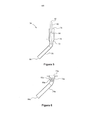
[0077] Estes e outros aspectos da presente invenção serão descritos agora, a título de exemplo, apenas com referência aos desenhos anexos, nos quais: a Figura 1 é uma vista longitudinal em seção transversal de um aparelho de tratamento de fluido de acordo com um modo de realização da presente invenção; a Figura 2 é uma vista lateral em seção transversal do aparelho na região de uma câmara superior; a Figura 3 é uma vista ampliada de uma região de entrada do primeiro aparelho mostrado na Figura 1; a Figura 4 é uma representação diagramática de padrões de fluxo antecipados no interior do aparelho da Figura 1; a Figura 5 é uma visão em seção transversal de um conjunto de bocal de acordo com um modo de realização da presente invenção, adequado para uso no aparelho da Figura 1; a Figura 6 é uma vista em seção transversal de um conjunto de bocal de acordo com um modo de realização alternativo da presente invenção, adequado para uso no aparelho da Figura 1, e A Figura 7 é uma representação diagramática de um aparelho de tratamento de fluidos de acordo com um modo de realização alternativo da presente invenção.[0077] These and other aspects of the present invention will now be described, by way of example, only with reference to the accompanying drawings, in which: Figure 1 is a longitudinal cross-sectional view of a fluid treatment apparatus according to a embodiment of the present invention; Figure 2 is a cross-sectional side view of the apparatus in the region of an upper chamber; Figure 3 is an enlarged view of an entrance region of the first apparatus shown in Figure 1; Figure 4 is a diagrammatic representation of anticipated flow patterns within the apparatus of Figure 1; Figure 5 is a cross-sectional view of a nozzle assembly according to an embodiment of the present invention, suitable for use in the apparatus of Figure 1; Figure 6 is a cross-sectional view of a nozzle assembly according to an alternative embodiment of the present invention, suitable for use in the apparatus of Figure 1, and Figure 7 is a diagrammatic representation of a fluid treatment apparatus. according to an alternative embodiment of the present invention.
[0078] É feita referência, primeiramente, às Figuras 1 e 2 dos desenhos, nas quais são mostradas vistas em seção transversal de um aparelho de tratamento de fluido, identificado, de modo geral, pelo numeral de referência 10 de acordo com um modo de realização da presente invenção. O aparelho 10 é mostrado na Figura 1, em seção transversal longitudinal e na Figura 2 em seção transversal lateral. O aparelho de tratamento de fluido 10 pode ser usado em muitas aplicações. No entanto, no presente modo de realização, o aparelho 10 é utilizado para tratar água produzida de um reservatório subterrâneo que compreende volumes de óleo e gás. Como será descrito abaixo em maior detalhe, o aparelho 10 é adaptado para separar o óleo e o gás da água produzida por separação por flotação. O aparelho 10 pode, por conseguinte, ser descrito como uma Unidade de Flotação Compacta (CFU).[0078] Reference is first made to Figures 1 and 2 of the drawings, in which cross-sectional views of a fluid treatment apparatus are shown, generally identified by the
[0079] O aparelho 10 compreende um vaso geralmente cilíndrico arranjado verticalmente 12 que define no mesmo uma primeira câmara de fluido ou câmara superior 14 e uma segunda câmara de fluido ou câmara inferior 16. As câmaras de fluido superior e inferior são separadas por uma divisória 18 fixada a uma superfície de parede interna do vaso 12. A divisória define uma base da câmara superior 14 e um teto da câmara inferior 16.The
[0080] Uma passagem de fluido 20 se estende entre as câmaras superior e inferior 14, 16 e é definida por uma porção de parede 22 se estendendo na vertical a partir da divisória 18. A porção de parede 22, em combinação com a superfície de parede interna do vaso 12 define uma região geralmente anular ou um canal 24 no interior da câmara superior 14. Como será descrito abaixo em maior detalhe, a passagem de fluido 20 permite comunicação de gás entre as câmaras superior e inferior 14, 16.[0080] A
[0081] Uma entrada de fluido 26 é formada em uma parede lateral do vaso 12 e, no uso, comunica a água produzida a ser tratada para a câmara de fluido superior 14 e, especificamente, para a região anular 24. Um conjunto distribuidor 28 é provido no interior da câmara superior 14 e é arranjado inicialmente para receber a água produzida que entra através da entrada 26. O conjunto distribuidor 28, que está mostrado mais claramente na Figura 2 e na vista ampliada na Figura 3, tem a forma de uma caixa definida pela divisória 18, a porção de parede 22, uma porção de parede interna do vaso 12, placas laterais perfuradas 30, e uma tampa sólida 32 (mostrada apenas na Figura 3). Desse modo, água produzida que entra na câmara superior 14 via entrada 26 será recebida, primeiramente, no conjunto distribuidor 28 e, em seguida, distribuída para a região anular 24 através das placas laterais perfuradas 30. O conjunto distribuidor 28 funciona para dissipar o momento da água produzida que entra e para distribuí-la para a região anular 24 com o mínimo de turbulência, impedindo ou minimizando o risco de respingos ou vazamento acidentais da água para a câmara inferior 16 através da passagem 20.[0081] A
[0082] O aparelho 10 compreende, adicionalmente, uma pluralidade de conjuntos de bocal ou edutores 34 que provêem comunicação fluida da água produzida proveniente da região anular 24 da câmara superior 14 para a câmara inferior 16. Desse modo, a câmara superior 14 recebe água produzida através da entrada de fluido 26 e, subsequentemente, a distribui para a câmara inferior 16 através dos conjuntos de bocal 34. A água produzida é, em seguida, submetida a um tratamento por flotação no interior da câmara inferior 16. Consequentemente, a câmara de fluido superior 14 pode definir uma câmara de distribuição e a câmara de fluido inferior 16 pode definir uma câmara de tratamento.[0082] The
[0083] Cada conjunto de bocal 34 facilita o carreamento de um gás para a água produzida escoando através do mesmo. O gás é carreado de uma região coletora 36 da câmara superior 14 e a turbulência e a mistura no interior de cada conjunto de bocal 34 configuram o gás carreado em pequenas bolhas e faz com que estas se misturem intimamente com a água produzida antes de ser descarregada para a câmara inferior 16. Desse modo, os conjuntos de bocal 34 dispensam água produzida para a câmara inferior 16 com uma distribuição favorável de bolhas de gás para o subsequente tratamento de fluido, na mesma. Isto é particularmente vantajoso devido ao fato do tempo de residência subsequente da água, no interior da câmara inferior 16, poder ser utilizado exclusivamente para o tratamento por flotação e para a separação do óleo e gás da água. Isto difere significativamente dos arranjos da técnica anterior nos quais a mistura de gás ocorre no interior de uma câmara de flotação e, desse modo, o tempo de residência deve acomodar tanto a mistura de gás, quanto a separação por flotação.[0083] Each set of
[0084] A forma dos conjuntos de bocal 34 será descrita abaixo em maior detalhe.[0084] The shape of the nozzle sets 34 will be described in more detail below.
[0085] À medida que a água produzida entra na câmara inferior 16, a água e o óleo começam, naturalmente, a se separar, com o óleo tendendo a flutuar na superfície da água. A presença de bolhas de gás bem distribuídas no interior da água produzida aumenta o efeito de separação pelo fato das bolhas aderirem às gotículas de óleo no interior da água, e ajuda a coalescência e flotação do óleo. Ao atingir a superfície da água, as bolhas de gás serão liberadas para uma região superior 90 da câmara inferior 16 e, subsequentemente, escoarão para a região de coleta 36 da câmara superior 14 através da passagem 20. Consequentemente, o gás liberado da água produzida pode reabastecer a região de coleta 36 para manter um volume de gás suficiente para carreamento para a entrada de água produzida pelos conjuntos de bocal 34.[0085] As the water produced enters the
[0086] O aparelho 10 compreende, adicionalmente, uma primeira saída 38 formada em uma região inferior da câmara inferior 16 e adaptada para facilitar a descarga de água tratada. Um defletor 40 e um rompedor de vórtice 42 também estão presentes no interior da região inferior da câmara inferior 16 e são adaptados para impedir que bolhas de gás sejam descarregadas através da primeira saída 38 com a água tratada. Conforme mostrado na Figura 1, o defletor 40 é posicionado concentricamente ao vaso 12 e tem um diâmetro que pode ser, aproximadamente, 80 a 95% do diâmetro interno do vaso 12.[0086] The
[0087] Um aparelho de escumadeira 44 é provido em uma região superior da câmara inferior 16 e é adaptado para escumar óleo da superfície da água. O óleo escumado é descarregado através de um tubo 46 e, finalmente, através de uma segunda saída 48 formada em um lado do vaso 12 acima da localização da divisória 18. O vaso 12 é mantido vantajosamente a uma pressão ligeiramente acima da pressão atmosférica para conduzir o óleo escumado para cima através do tubo 46 em direção à segunda saída 48. O óleo pode, então, ser coletado e processado conforme necessário. Em um arranjo alternativo, o tubo 46 pode se prolongar descendentemente a partir do aparelho de escumadeira 44 e descarregar através de uma saída em uma região inferior do vaso 12, por exemplo, de uma região basal, abaixo do defletor 40.[0087] A
[0088] O aparelho de escumadeira 44 é auto-nivelável, de modo que uma região de escumadeira superior 50 é mantida em uma posição predefinida em relação à superfície da água/óleo na câmara inferior 16, para preservar a escumagem eficiente do óleo.[0088] The
[0089] É provida uma terceira saída 52 na região superior da câmara superior 14 e esta permite que o gás na região de coleta 36 possa ser descarregado do vaso 12. O gás pode ser coletado, queimado, reciclado ou similar. A saída 52 também pode funcionar como uma entrada para permitir que gás seja suprido ao vaso 12.[0089] A
[0090] No presente modo de realização, os conjuntos de bocal 34 compreendem canos de descarga 54 que ficam parcialmente imersos na água produzida na câmara inferior 16 e são arranjados em uma direção comum para descarregar a água produzida descendente e circunferencialmente em relação ao vaso 12. Este arranjo efetua a rotação da água no interior da câmara inferior 16, o que ajuda, vantajosamente, o tratamento de fluido na mesma e provê movimentação preferencial de bolhas de gás no interior do fluido e óleo flutuante em direção ao conjunto de escumadeira 44. Além disso, a rotação da água produzida ajuda a impedir que a água passe através da câmara inferior 16 sem prover tempo suficiente para que as bolhas de gás e as gotículas de óleo se separem da água.[0090] In the present embodiment, the
[0091] Um arranjo de defletor na forma de um defletor anular 55 pode ser opcionalmente fixado ou formado integralmente com a parede da câmara inferior 16 em uma região abaixo dos tubos de descarga 54 dos conjuntos de bocal 34. No uso, o defletor 55 minimiza uma componente de velocidade descendente do fluido para ajudar a minimizar mistura à frente de líquido.[0091] A baffle arrangement in the form of an annular baffle 55 can optionally be fixed or integrally formed with the
[0092] Embora não ilustrado, o defletor 55 inclui inúmeros orifícios de modo a permitir a liberação de qualquer matéria sólida que possa ser coletada sobre uma superfície superior do mesmo.[0092] Although not illustrated, the deflector 55 includes numerous holes in order to allow the release of any solid matter that can be collected on its upper surface.
[0093] É feita referência agora à Figura 4 dos desenhos, na qual é mostrada uma representação diagramática de um padrão antecipado de fluxo no interior do vaso 12. O lado à esquerda do vaso 12, mostrado na Figura 2, ilustra um padrão antecipado de fluxo secundário de água, e o lado à direita mostra as trajetórias antecipadas de bolhas no interior da câmara inferior 16. Deve ser entendido que o movimento rotativo primário do fluido ao redor do eixo longitudinal central do vaso 12 não está representado na Figura 4 para maior clareza. Além disso, o defletor anular opcional 55, mostrado na Figura 1, não é mostrado na Figura 4.[0093] Reference is now made to Figure 4 of the drawings, in which a diagrammatic representation of an anticipated flow pattern is shown inside
[0094] Um circuito fechado de circulação lateral 60 (circuito fechado 1) é acionado pela subida de gás das bolhas grandes 62 descarregadas dos conjuntos de bocal 34 subindo rapidamente para a superfície. O circuito fechado de circulação 60 assegura que o fluxo sobre a superfície de líquido seja em direção ao conjunto de escumadeira 44, de modo que o óleo separado 64 possa ser carreado nesta direção. Um circuito fechado de circulação longitudinal 66 (circuito fechado 2) é acionado por fluxo radialmente para dentro na camada limite de líquido 68 sobre o defletor 40. O circuito fechado de circulação 66 captura as pequenas bolhas de gás 70, que têm trajetórias descendentes para fora do fluxo principal de água e as transporta em direção ao centro e, em seguida, para cima, em direção à superfície, para serem capturadas pelo circuito fechado de circulação 60. As pequenas bolhas de gás 70 devem, por conseguinte, atravessar para o circuito de circulação 60 para, finalmente, chegar à superfície, e/ou coalescer em bolhas maiores.[0094] A closed circulation loop 60 (closed loop 1) is triggered by the gas rising from the
[0095] Uma descrição detalhada da forma de um conjunto de bocal 34 será descrita agora com referência à Figura 5, na qual o conjunto de bocal 34 é mostrado em vista secional. O conjunto 34 compreende um primeiro conduto de fluido 72 que se estende para cima e define uma porta de entrada de fluido 74. Uma extremidade inferior do primeiro conduto é fixada ao cano de descarga inclinado 54. A primeira porta de fluido 74 permite que água produzida na região anular 24 (ver Figura 1) escoe para o primeiro conduto 72 e, desse modo, para o tubo de descarga 54. Um flange 78 é fixado ao primeiro conduto de fluido 72 e permite que o conjunto de bocal 34 seja fixado à divisória 18 (ver Figura 1), separando as câmaras superior e inferior 14, 16.[0095] A detailed description of the shape of a
[0096] O conjunto 34 também compreende um segundo conduto de fluido 80 que se estende através do primeiro conduto de fluido 72. O segundo conduto 80 define uma porta de fluido superior 82 que se abre para a região de coleta 36 (ver Figura 1). Uma extremidade inferior do segundo conduto 80 é aberta na região do tubo de descarga 54.[0096]
[0097] Desse modo, no uso, água escoando através do primeiro conduto de fluido 72 fará com que gás seja carreado do segundo conduto de fluido 80, proveniente da região de coleta 36 e subsequentemente misturado no interior do tubo de descarga 54, sendo estabelecida, desse modo, uma boa distribuição de bolhas de gás no interior da água antes de ser descarregada através de uma saída 84 para a câmara inferior 16.[0097] Thus, in use, water draining through the first
[0098] A altura da porta de fluido 74 do primeiro conduto de fluido ditará o gradiente de fluido no interior da região anular 24, necessário para o conjunto de bocal 34 operar. Este gradiente operacional pode ser variado e pré-selecionado pela provisão de um tubo de extensão 86 de um comprimento necessário, fixado ou formado integralmente com o primeiro conduto de fluido 72. O gradiente operacional dos conjuntos de bocal 34 pode ficar na região de 400-500mm, por exemplo.[0098] The height of the
[0099] Em um modo de realização de aspectos da presente invenção, o gradiente operacional pode ser equivalente para todos os conjuntos de bocal 34 providos no interior do aparelho. Entretanto, em modos de realização alternativos, dois ou mais conjuntos de bocal 34 podem ser providos com gradientes operacionais diferentes, pelo arranjo das respectivas portas de fluido 74 em alturas diferentes. Consequentemente, neste arranjo, caso o gradiente ou nível de fluido no interior da região anular 24 da câmara superior 14 começar a cair, por exemplo, como resultado de uma vazão de fluxo reduzida através da entrada 26, os conjuntos de bocal 34 se tornarão sequencialmente ineficazes, em conformidade com as alturas das respectivas portas de fluido 74, até que o fluxo, passando através do número reduzido de conjuntos de bocal 34 em operação, para a segunda câmara 16, se case com o fluxo entrando na região anular 24 proveniente da entrada 26. Esse arranjo pode, por conseguinte, ser utilizado para manter uma faixa de velocidade preferida do fluido sendo descarregado através das saídas 84 dos tubos de descarga 54 para a segunda câmara de fluido 16. A faixa de velocidade preferida pode ser selecionada de acordo com o fluxo necessário no interior da segunda câmara de fluido 16. Por exemplo, uma faixa de velocidades de descarga de fluido pode ser necessária para estabelecer e manter o fluxo rotativo no interior da câmara inferior. A faixa de velocidade preferida também pode ser selecionada para manter a proporção de gás carreado no interior do fluido e a mistura entre eles, o que ocorre no tubo de descarga dentro de valores preferidos.[0099] In an embodiment of aspects of the present invention, the operational gradient can be equivalent for all
[00100] Um modo de realização alternativo de um conjunto de bocais 34 que pode ser utilizado no aparelho 10 mostrado primeiramente na Figura 1, é mostrado na Figura 6, à qual será feita agora referência. O conjunto 34a, da Figura 6, é similar ao conjunto 34 na Figura 5 e, como tal, componentes iguais compartilham numerais de referência iguais, seguidos da letra “a”. Como se nota, o conjunto de bocal 34a é similar ao conjunto 34 e, como tal, compreende um primeiro conduto de fluido 72a definindo uma porta de fluido 74a, e um segundo conduto de fluido 80a definindo uma porta de fluido 82a. Entretanto, neste modo de realização, a porta de fluido 82 do segundo conduto de fluido 80a se abre para uma região de coleta 90 (ver Figura 1) da câmara inferior 16. Desse modo, gás da região de coleta 90 pode ser carreado e misturado com água produzida no interior de um tubo de descarga 54 antes de ser descarregada através de uma saída 84 para a câmara inferior 16. Embora não ilustrado, o conjunto de bocal 34a pode incluir um tubo de extensão, similar ao tubo 86 do exemplo mostrado na Figura 5.[00100] An alternative embodiment of a set of
[00101] Um aparelho de tratamento de fluido de acordo com um modo de realização alternativo da presente invenção será descrito agora com referência à Figura 7. O aparelho de tratamento de fluido, identificado, de modo geral, pelo numeral de referência 110, é similar ao aparelho 10 mostrado primeiramente na Figura 1 e, como tal, características iguais compartilham numerais de referência iguais, incrementados por 100.[00101] A fluid treatment apparatus according to an alternative embodiment of the present invention will now be described with reference to Figure 7. The fluid treatment apparatus, generally identified by
[00102] Por conseguinte, o aparelho 110 compreende um vaso 112 que, neste caso, fica arranjado horizontalmente. Primeira e segunda câmaras de fluido 114, 116, separadas por uma divisória 118, são definidas no interior do vaso 12. É provida uma passagem de fluido 120 entre as primeira e segunda câmaras 114, 116 para permitir a passagem de gás entre elas. Uma entrada de fluido 126 comunica água produzida para a primeira câmara 114, e uma pluralidade de conjuntos de bocal 134 é provida para permitir a comunicação da água produzida proveniente da primeira câmara 114 e para a segunda câmara 116. Os conjuntos de bocal 134 facilitam o carreamento de um gás no interior de uma região de coleta 136 da primeira câmara 114, ou de uma região de coleta 190 da segunda câmara 116, para a água produzida. Por conseguinte, este arranjo provê uma boa mistura e distribuição de bolhas de gás no interior do fluido produzido antes de ser descarregado para a segunda câmara 116.Accordingly, the
[00103] O fluido produzido pode, então, permanecer por um período de tempo no interior da segunda câmara 116, de modo que o gás e o óleo na água possam flutuar para superfície do mesmo, enquanto a água se move em uma direção geralmente da esquerda para a direita. Defletores perfurados 92, de preferência pelo menos dois, são providos no interior da segunda câmara 116 a impedir retromistura da água.[00103] The produced fluid can then remain for a period of time inside the
[00104] A água tratada com teor de gás e óleo significativamente reduzido pode ser descarregada através de uma primeira saída 138. O óleo flutuante pode ser escumado da superfície da água por um conjunto de escumadeira 144 e subsequentemente descarregado através de uma segunda saída 148. O gás liberado da água pode ser descarregado através de uma terceira saída 152.[00104] Treated water with significantly reduced gas and oil content can be discharged through a
[00105] Deve ser entendido que os modos de realização aqui descritos são exemplificativos e que várias modificações podem ser feitas nos mesmos, sem se afastar do escopo da presente invenção. Por exemplo, características da presente invenção descritas acima, podem ser utilizadas em circunstâncias em que as primeira e segunda câmaras são providas em vasos separados. Neste arranjo, os benefícios da presente invenção ainda podem ser obtidos em virtude da passagem da água produzida a ser tratada através dos conjuntos de bocal, de modo que uma boa mistura e distribuição de bolhas no interior da água seja obtida antes de ser descarregada para a segunda câmara de fluido para tratamento. Em outros modos de realização a primeira câmara pode ser dispensada e, fluido proveniente de uma fonte pode ser suprido diretamente a pelo menos um conjunto de bocal para ser descarregado para uma câmara de tratamento de fluido.[00105] It should be understood that the embodiments described herein are exemplary and that various modifications can be made to them, without departing from the scope of the present invention. For example, features of the present invention described above, can be used in circumstances where the first and second chambers are provided in separate vessels. In this arrangement, the benefits of the present invention can still be obtained by virtue of the passage of the produced water to be treated through the nozzle assemblies, so that a good mixture and distribution of bubbles inside the water is obtained before being discharged into the water. second fluid chamber for treatment. In other embodiments, the first chamber can be dispensed and fluid from a source can be supplied directly to at least one nozzle assembly to be discharged to a fluid treatment chamber.
[00106] Além disso, nos modos de realização descritos, vários condutos e passagens são providos e localizados internamente ao vaso. Entretanto, estes condutos e passagens podem se estender total, ou pelo menos parcialmente, externamente ao vaso.[00106] In addition, in the described embodiments, various ducts and passages are provided and located internally to the vessel. However, these conduits and passages can extend totally, or at least partially, outside the vessel.
[00107] Além disso, o aparelho pode compreender uma terceira câmara de fluido adaptada para receber fluido proveniente da segunda câmara de fluido para tratamento adicional. Fluido comunicado da segunda câmara de fluido para a terceira câmara de fluido pode ser provido através de pelo menos um conjunto de bocal.[00107] In addition, the apparatus may comprise a third fluid chamber adapted to receive fluid from the second fluid chamber for further treatment. Communicated fluid from the second fluid chamber to the third fluid chamber can be provided through at least one nozzle assembly.
[00108] Além disso, o gás a ser carreado para o fluido sendo tratado pode ser provido proveniente de uma fonte externa.[00108] In addition, the gas to be carried into the fluid being treated can be provided from an external source.
[00109] O vaso pode ser aberto para a atmosfera.[00109] The vessel can be opened to the atmosphere.
[00110] Embora os conjuntos de bocal sejam arranjados para carrear gás para o fluido sendo tratado, em arranjos alternativos, pelo menos um dos conjuntos de bocal pode ser adaptado para permitir que gás seja injetado ou dispensado, de outra maneira, para o fluido sendo tratado.[00110] Although the nozzle assemblies are arranged to carry gas to the fluid being treated, in alternative arrangements, at least one of the nozzle assemblies can be adapted to allow gas to be injected or otherwise dispensed into the fluid being treated.
Claims (21)
Applications Claiming Priority (3)
| Application Number | Priority Date | Filing Date | Title |
|---|---|---|---|
| GBGB0809603.4A GB0809603D0 (en) | 2008-05-28 | 2008-05-28 | Fluid treatment apparatus |
| GB0809603.4 | 2008-05-28 | ||
| PCT/GB2009/001031 WO2009144441A1 (en) | 2008-05-28 | 2009-04-22 | Fluid treatment apparatus |
Publications (3)
| Publication Number | Publication Date |
|---|---|
| BRPI0912146A2 BRPI0912146A2 (en) | 2020-06-30 |
| BRPI0912146B1 true BRPI0912146B1 (en) | 2021-02-02 |
| BRPI0912146B8 BRPI0912146B8 (en) | 2021-03-30 |
Family
ID=39616152
Family Applications (1)
| Application Number | Title | Priority Date | Filing Date |
|---|---|---|---|
| BRPI0912146A BRPI0912146B8 (en) | 2008-05-28 | 2009-04-22 | fluid treatment apparatus, method for treating a fluid, and nozzle arrangement |
Country Status (13)
| Country | Link |
|---|---|
| EP (2) | EP2572769B1 (en) |
| JP (2) | JP5687189B2 (en) |
| KR (2) | KR101672964B1 (en) |
| CN (2) | CN102083509A (en) |
| AR (1) | AR071919A1 (en) |
| AU (1) | AU2009252981B2 (en) |
| BR (1) | BRPI0912146B8 (en) |
| CA (1) | CA2725589C (en) |
| DK (1) | DK2280774T3 (en) |
| GB (1) | GB0809603D0 (en) |
| MX (1) | MX2010013017A (en) |
| MY (1) | MY183535A (en) |
| WO (1) | WO2009144441A1 (en) |
Families Citing this family (7)
| Publication number | Priority date | Publication date | Assignee | Title |
|---|---|---|---|---|
| US8900460B2 (en) * | 2011-09-29 | 2014-12-02 | Cameron International Corporation | Method to process effluent brine and interface rag from an oil dehydration/desalting system |
| WO2015188850A1 (en) * | 2014-06-10 | 2015-12-17 | Abb S.P.A. | Subsea separator |
| DE102014217226B4 (en) * | 2014-08-28 | 2021-09-23 | Skf Blohm + Voss Industries Gmbh | Evaporation plant, evaporation process and sealing system |
| CN106975375B (en) * | 2017-05-02 | 2023-09-26 | 江苏揽山环境科技股份有限公司 | Microbubble device, desulfurization equipment, oxidation and method for improving oxygen content of water body |
| WO2020222328A1 (en) * | 2019-04-29 | 2020-11-05 | 씨에이티 주식회사 | Fluid processing device |
| WO2021106500A1 (en) * | 2019-11-27 | 2021-06-03 | 株式会社クレハ | Device and method for treating water of interest |
| US20230091302A1 (en) * | 2021-09-23 | 2023-03-23 | Worldwide Oilfield Machine, Inc. | System and method for plug milling / flow-back / live descaling integrated improved workflow operations |
Family Cites Families (29)
| Publication number | Priority date | Publication date | Assignee | Title |
|---|---|---|---|---|
| US2410429A (en) * | 1944-03-06 | 1946-11-05 | Mining Process & Patent Co | Agitation and aeration apparatus |
| DE1036214B (en) * | 1952-09-06 | 1958-08-14 | Sulzer Ag | Device for mixing a gas with a liquid |
| FR1499649A (en) * | 1966-11-08 | 1967-10-27 | Ingtech Zentralbuero Veb | Process for the gas treatment of liquids and installation for implementing this process |
| US3945922A (en) * | 1974-06-20 | 1976-03-23 | Veb Chemieanlagenbau-Und Montegekombinat | Installation for charging liquids, particularly fermentation liquids, with gas |
| JPS51101266A (en) * | 1975-03-04 | 1976-09-07 | Kazue Tanaka | Joshokihono atsuryokunyorujusuibunrisochi |
| CH600938A5 (en) * | 1975-12-10 | 1978-06-30 | Sulzer Ag | |
| JPS5349159U (en) * | 1976-09-30 | 1978-04-25 | ||
| JPS56129010A (en) * | 1980-03-13 | 1981-10-08 | Mitsubishi Electric Corp | Oil-water separator |
| JPS592435U (en) * | 1982-06-25 | 1984-01-09 | 三菱重工業株式会社 | floating sorter |
| JPH07121387B2 (en) * | 1987-11-16 | 1995-12-25 | 年臣 永田 | Organic wastewater treatment method |
| CN2030106U (en) * | 1988-04-02 | 1989-01-04 | 于忠民 | Gravity separator for solid oil and water |
| US4986903A (en) * | 1988-10-11 | 1991-01-22 | Canzoneri Anthony S | Induced static single flotation cell |
| JPH0316687A (en) * | 1989-06-12 | 1991-01-24 | Hetsuzu:Kk | High-speed waste water treating device |
| US5106590A (en) * | 1990-05-11 | 1992-04-21 | Davy Mckee (London) Limited | Gas mixer and distributor with heat exchange between incoming gases |
| JPH0478492A (en) * | 1990-07-19 | 1992-03-12 | Masashi Tsuchida | Aerator |
| US5227061A (en) * | 1992-01-13 | 1993-07-13 | Bedsole Robert D | Fuel/contaminant separator |
| JP3316392B2 (en) * | 1996-09-25 | 2002-08-19 | 三菱重工業株式会社 | Underwater aeration equipment |
| JP2000070692A (en) * | 1998-09-02 | 2000-03-07 | Sony Corp | Diffuser hose joint structure |
| US6109449A (en) * | 1998-11-04 | 2000-08-29 | General Signal Corporation | Mixing system for separation of materials by flotation |
| KR20010097084A (en) * | 2000-04-20 | 2001-11-08 | 김무영 | Sludge and oil sepanator and a method thereof |
| EP1208897A1 (en) * | 2000-11-21 | 2002-05-29 | Epcon Norge AS | Combined degassing and flotation tank |
| CN2550026Y (en) * | 2002-06-21 | 2003-05-14 | 殷叶龙 | Combined oil and water separator of cyclone hydraulic jet flow coarse graining |
| US6832754B2 (en) * | 2003-03-18 | 2004-12-21 | Alan Cross | Gas-liquid contactor |
| US7157007B2 (en) * | 2003-06-20 | 2007-01-02 | National Tank Company | Vertical gas induced flotation cell |
| DE102004024957A1 (en) * | 2004-05-22 | 2005-12-22 | Uhde Gmbh | Device, useful for passing oxygen that is added in pure form into a reaction gas, comprises an oxygen distribution element from two tubes and a multitude of flow pipes before the arrangement for receiving catalyst filling |
| US7597801B2 (en) * | 2004-06-15 | 2009-10-06 | Ecodays Co., Ltd. | Fluids fluxion method and plant for wastewater treatment |
| FI122973B (en) * | 2005-06-17 | 2012-09-28 | Metso Paper Inc | Injector for flotation cell, nozzle part in injector for flotation cell, flotation cell and method for mixing fiber suspension strip and air with each other in injector for flotation cell |
| CN2875546Y (en) * | 2006-03-06 | 2007-03-07 | 杨亚设 | Oil water separating device |
| JP2008093515A (en) * | 2006-10-06 | 2008-04-24 | Anemosu:Kk | Fluid mixer and fluid-mixing device |
-
2008
- 2008-05-28 GB GBGB0809603.4A patent/GB0809603D0/en not_active Ceased
-
2009
- 2009-04-22 WO PCT/GB2009/001031 patent/WO2009144441A1/en active Application Filing
- 2009-04-22 MY MYPI2010005682A patent/MY183535A/en unknown
- 2009-04-22 CA CA2725589A patent/CA2725589C/en not_active Expired - Fee Related
- 2009-04-22 EP EP12198273.0A patent/EP2572769B1/en not_active Not-in-force
- 2009-04-22 CN CN2009801248919A patent/CN102083509A/en active Pending
- 2009-04-22 AU AU2009252981A patent/AU2009252981B2/en not_active Ceased
- 2009-04-22 JP JP2011511078A patent/JP5687189B2/en not_active Expired - Fee Related
- 2009-04-22 BR BRPI0912146A patent/BRPI0912146B8/en active IP Right Grant
- 2009-04-22 MX MX2010013017A patent/MX2010013017A/en active IP Right Grant
- 2009-04-22 CN CN201510970881.4A patent/CN105477905B/en active Active
- 2009-04-22 KR KR1020107028849A patent/KR101672964B1/en active IP Right Grant
- 2009-04-22 KR KR1020167020344A patent/KR20160092056A/en not_active Application Discontinuation
- 2009-04-22 DK DK09754086.8T patent/DK2280774T3/en active
- 2009-04-22 EP EP09754086.8A patent/EP2280774B1/en not_active Not-in-force
- 2009-05-27 AR ARP090101895A patent/AR071919A1/en unknown
-
2014
- 2014-11-17 JP JP2014233176A patent/JP2015083302A/en active Pending
Also Published As
| Publication number | Publication date |
|---|---|
| JP5687189B2 (en) | 2015-03-18 |
| AU2009252981A1 (en) | 2009-12-03 |
| CN105477905B (en) | 2018-07-10 |
| JP2015083302A (en) | 2015-04-30 |
| BRPI0912146B8 (en) | 2021-03-30 |
| JP2011521780A (en) | 2011-07-28 |
| KR20160092056A (en) | 2016-08-03 |
| MX2010013017A (en) | 2011-05-25 |
| WO2009144441A1 (en) | 2009-12-03 |
| EP2572769B1 (en) | 2017-01-04 |
| AR071919A1 (en) | 2010-07-21 |
| AU2009252981B2 (en) | 2014-07-24 |
| EP2572769A1 (en) | 2013-03-27 |
| CN102083509A (en) | 2011-06-01 |
| KR20110017394A (en) | 2011-02-21 |
| KR101672964B1 (en) | 2016-11-16 |
| MY183535A (en) | 2021-02-25 |
| BRPI0912146A2 (en) | 2020-06-30 |
| GB0809603D0 (en) | 2008-07-02 |
| EP2280774B1 (en) | 2014-01-08 |
| CN105477905A (en) | 2016-04-13 |
| EP2280774A1 (en) | 2011-02-09 |
| CA2725589A1 (en) | 2009-12-03 |
| DK2280774T3 (en) | 2014-04-07 |
| CA2725589C (en) | 2016-10-11 |
Similar Documents
| Publication | Publication Date | Title |
|---|---|---|
| US8771520B2 (en) | Fluid treatment apparatus | |
| BRPI0912146B1 (en) | fluid treatment apparatus, and method for treating a fluid | |
| US4255262A (en) | Hydraulic powered mixing apparatus | |
| ES2234893T3 (en) | COMBINED TANK DEGASIFICATION AND FLOATING. | |
| KR100812668B1 (en) | Pure Oxygen Aeration Device for Wastewater Treatment | |
| KR101287374B1 (en) | Separator to separate a liquid/liquid/gas/solid mixture | |
| HUT76175A (en) | Separator and separating method for the separation of a first fluid from a second fluid | |
| BR112018069358B1 (en) | APPLIANCE FOR SEPARATION OF HYDROCARBONS FROM WATER | |
| JPS5810160B2 (en) | water biological purification equipment | |
| BR102017023118A2 (en) | FIRST-STAGE MULTI-PHASE SEPARATOR, AND MULTI-PHASE FLUID SEPARATION METHOD | |
| US9174223B2 (en) | Compact separation apparatus | |
| ES2642211T3 (en) | Skimming Deposit Settings and Methods | |
| BRPI0619574A2 (en) | method and apparatus for separating submerged particles from a fluid | |
| KR101200290B1 (en) | Air dossolving tube and dissolved air injection type flotation tank | |
| BR0111758B1 (en) | apparatus for removing suspended matter from a liquid and method for clearing a liquid from suspended matter. | |
| JP4281691B2 (en) | Pressure floating separator | |
| FI122408B (en) | Apparatus and method for separating gas from flotation foam | |
| JP2008049227A (en) | Floatation separation apparatus | |
| JP3021459U (en) | Solid-liquid separator | |
| JP2007152283A (en) | Pressure flotation separation apparatus | |
| PL229584B1 (en) | Separator for inhomogeneous liquid mixtures |
Legal Events
| Date | Code | Title | Description |
|---|---|---|---|
| B06F | Objections, documents and/or translations needed after an examination request according [chapter 6.6 patent gazette] | ||
| B06U | Preliminary requirement: requests with searches performed by other patent offices: procedure suspended [chapter 6.21 patent gazette] | ||
| B07A | Application suspended after technical examination (opinion) [chapter 7.1 patent gazette] | ||
| B09A | Decision: intention to grant [chapter 9.1 patent gazette] | ||
| B16A | Patent or certificate of addition of invention granted [chapter 16.1 patent gazette] |
Free format text: PRAZO DE VALIDADE: 10 (DEZ) ANOS CONTADOS A PARTIR DE 02/02/2021, OBSERVADAS AS CONDICOES LEGAIS. |
|
| B16C | Correction of notification of the grant [chapter 16.3 patent gazette] |
Free format text: REF. RPI 2613 DE 02/02/2021 QUANTO AO ENDERECO. |