BRPI0814513B1 - AIR FILTER CARTRIDGE AND AIR FILTER ASSEMBLY - Google Patents
AIR FILTER CARTRIDGE AND AIR FILTER ASSEMBLY Download PDFInfo
- Publication number
- BRPI0814513B1 BRPI0814513B1 BRPI0814513-0A BRPI0814513A BRPI0814513B1 BR PI0814513 B1 BRPI0814513 B1 BR PI0814513B1 BR PI0814513 A BRPI0814513 A BR PI0814513A BR PI0814513 B1 BRPI0814513 B1 BR PI0814513B1
- Authority
- BR
- Brazil
- Prior art keywords
- end cap
- cartridge
- projection
- air filter
- housing
- Prior art date
Links
- WYTGDNHDOZPMIW-RCBQFDQVSA-N alstonine Natural products C1=CC2=C3C=CC=CC3=NC2=C2N1C[C@H]1[C@H](C)OC=C(C(=O)OC)[C@H]1C2 WYTGDNHDOZPMIW-RCBQFDQVSA-N 0.000 claims description 53
- 238000007789 sealing Methods 0.000 claims description 17
- 238000000034 method Methods 0.000 abstract description 7
- 239000000463 material Substances 0.000 description 9
- 238000012423 maintenance Methods 0.000 description 8
- 238000000576 coating method Methods 0.000 description 6
- 239000000428 dust Substances 0.000 description 6
- 238000011049 filling Methods 0.000 description 6
- 239000004033 plastic Substances 0.000 description 6
- 229920003023 plastic Polymers 0.000 description 6
- 239000002184 metal Substances 0.000 description 5
- XLYOFNOQVPJJNP-UHFFFAOYSA-N water Substances O XLYOFNOQVPJJNP-UHFFFAOYSA-N 0.000 description 5
- 238000003491 array Methods 0.000 description 4
- 239000000853 adhesive Substances 0.000 description 3
- 230000001070 adhesive effect Effects 0.000 description 3
- 230000008901 benefit Effects 0.000 description 3
- 238000001914 filtration Methods 0.000 description 3
- 238000007689 inspection Methods 0.000 description 3
- 238000009434 installation Methods 0.000 description 3
- 229920002635 polyurethane Polymers 0.000 description 3
- 239000004814 polyurethane Substances 0.000 description 3
- 239000007787 solid Substances 0.000 description 3
- 239000011248 coating agent Substances 0.000 description 2
- 238000002485 combustion reaction Methods 0.000 description 2
- 238000003780 insertion Methods 0.000 description 2
- 230000037431 insertion Effects 0.000 description 2
- 239000004743 Polypropylene Substances 0.000 description 1
- 229920005830 Polyurethane Foam Polymers 0.000 description 1
- 238000007792 addition Methods 0.000 description 1
- 230000004888 barrier function Effects 0.000 description 1
- 230000000903 blocking effect Effects 0.000 description 1
- 239000003795 chemical substances by application Substances 0.000 description 1
- 238000010276 construction Methods 0.000 description 1
- 238000002347 injection Methods 0.000 description 1
- 239000007924 injection Substances 0.000 description 1
- 230000003993 interaction Effects 0.000 description 1
- 238000000465 moulding Methods 0.000 description 1
- 239000006223 plastic coating Substances 0.000 description 1
- -1 polypropylene Polymers 0.000 description 1
- 229920001155 polypropylene Polymers 0.000 description 1
- 239000011496 polyurethane foam Substances 0.000 description 1
- 238000004382 potting Methods 0.000 description 1
- 238000003908 quality control method Methods 0.000 description 1
- 239000011347 resin Substances 0.000 description 1
- 229920005989 resin Polymers 0.000 description 1
- 238000000926 separation method Methods 0.000 description 1
Images


Classifications
-
- B—PERFORMING OPERATIONS; TRANSPORTING
- B01—PHYSICAL OR CHEMICAL PROCESSES OR APPARATUS IN GENERAL
- B01D—SEPARATION
- B01D46/00—Filters or filtering processes specially modified for separating dispersed particles from gases or vapours
- B01D46/24—Particle separators, e.g. dust precipitators, using rigid hollow filter bodies
- B01D46/2403—Particle separators, e.g. dust precipitators, using rigid hollow filter bodies characterised by the physical shape or structure of the filtering element
- B01D46/2411—Filter cartridges
- B01D46/2414—End caps including additional functions or special forms
-
- B—PERFORMING OPERATIONS; TRANSPORTING
- B01—PHYSICAL OR CHEMICAL PROCESSES OR APPARATUS IN GENERAL
- B01D—SEPARATION
- B01D46/00—Filters or filtering processes specially modified for separating dispersed particles from gases or vapours
- B01D46/0084—Filters or filtering processes specially modified for separating dispersed particles from gases or vapours provided with safety means
- B01D46/009—Identification of filter type or position thereof, e.g. by transponders or bar codes
-
- B—PERFORMING OPERATIONS; TRANSPORTING
- B01—PHYSICAL OR CHEMICAL PROCESSES OR APPARATUS IN GENERAL
- B01D—SEPARATION
- B01D46/00—Filters or filtering processes specially modified for separating dispersed particles from gases or vapours
- B01D46/52—Particle separators, e.g. dust precipitators, using filters embodying folded corrugated or wound sheet material
-
- B—PERFORMING OPERATIONS; TRANSPORTING
- B01—PHYSICAL OR CHEMICAL PROCESSES OR APPARATUS IN GENERAL
- B01D—SEPARATION
- B01D46/00—Filters or filtering processes specially modified for separating dispersed particles from gases or vapours
- B01D46/56—Filters or filtering processes specially modified for separating dispersed particles from gases or vapours with multiple filtering elements, characterised by their mutual disposition
- B01D46/62—Filters or filtering processes specially modified for separating dispersed particles from gases or vapours with multiple filtering elements, characterised by their mutual disposition connected in series
- B01D46/64—Filters or filtering processes specially modified for separating dispersed particles from gases or vapours with multiple filtering elements, characterised by their mutual disposition connected in series arranged concentrically or coaxially
-
- F—MECHANICAL ENGINEERING; LIGHTING; HEATING; WEAPONS; BLASTING
- F02—COMBUSTION ENGINES; HOT-GAS OR COMBUSTION-PRODUCT ENGINE PLANTS
- F02M—SUPPLYING COMBUSTION ENGINES IN GENERAL WITH COMBUSTIBLE MIXTURES OR CONSTITUENTS THEREOF
- F02M35/00—Combustion-air cleaners, air intakes, intake silencers, or induction systems specially adapted for, or arranged on, internal-combustion engines
- F02M35/02—Air cleaners
- F02M35/024—Air cleaners using filters, e.g. moistened
- F02M35/02416—Fixing, mounting, supporting or arranging filter elements; Filter element cartridges
-
- F—MECHANICAL ENGINEERING; LIGHTING; HEATING; WEAPONS; BLASTING
- F02—COMBUSTION ENGINES; HOT-GAS OR COMBUSTION-PRODUCT ENGINE PLANTS
- F02M—SUPPLYING COMBUSTION ENGINES IN GENERAL WITH COMBUSTIBLE MIXTURES OR CONSTITUENTS THEREOF
- F02M35/00—Combustion-air cleaners, air intakes, intake silencers, or induction systems specially adapted for, or arranged on, internal-combustion engines
- F02M35/02—Air cleaners
- F02M35/024—Air cleaners using filters, e.g. moistened
- F02M35/02475—Air cleaners using filters, e.g. moistened characterised by the shape of the filter element
- F02M35/02483—Cylindrical, conical, oval, spherical or the like filter elements; wounded filter elements
-
- B—PERFORMING OPERATIONS; TRANSPORTING
- B01—PHYSICAL OR CHEMICAL PROCESSES OR APPARATUS IN GENERAL
- B01D—SEPARATION
- B01D2265/00—Casings, housings or mounting for filters specially adapted for separating dispersed particles from gases or vapours
- B01D2265/02—Non-permanent measures for connecting different parts of the filter
- B01D2265/021—Anti-rotational means
-
- B—PERFORMING OPERATIONS; TRANSPORTING
- B01—PHYSICAL OR CHEMICAL PROCESSES OR APPARATUS IN GENERAL
- B01D—SEPARATION
- B01D2265/00—Casings, housings or mounting for filters specially adapted for separating dispersed particles from gases or vapours
- B01D2265/02—Non-permanent measures for connecting different parts of the filter
- B01D2265/024—Mounting aids
- B01D2265/026—Mounting aids with means for avoiding false mounting
Abstract
disposição em filtro de ar com suporte de extremidade para cartucho; componentes e métodos é descrito e mostrado um conjunto filtro de ar que inclui um alojamento com uma entrada de fluxo de ar, uma saída de fluxo de ar, um corpo de alojamento e proteção de acesso. um cartucho de filtro que pode passar por manutenção é posicionado no alojamento. um arranjo projeção / recepção que fornece encaixe entre o cartucho e a proteção de acesso é fornecido. o arranjo projeção / recepção pode ser configurado de uma maneira que inibe tanto movimento em cantiléver quanto movimento rotativo do cartucho já instalado. é fornecido um arranjo projeção / recepção de exemplo que inclui uma ranhura receptora de serpentina na proteção de acesso e uma projeção da serpentina no cartucho de filtro.air filter arrangement with end support for cartridge; Components and Methods An air filter assembly is described and shown that includes a housing with an airflow inlet, an airflow outlet, a housing body and access protection. A serviceable filter cartridge is positioned in the housing. A projection/reception arrangement that provides fit between the cartridge and the access shield is provided. The projection/reception arrangement can be configured in a manner that inhibits both cantilever movement and rotary movement of the already installed cartridge. An example projection/reception arrangement is provided that includes a coil receiving slot in the access shield and a coil projection in the filter cartridge.
Description
[001] Este pedido está sendo depositado em 17 de julho de 2008, como um pedido de patente internacional PCT em nome de Donaldson Company, Inc., uma corporação nacional dos EUA, requerente para a designação em todos os países, exceto os EUA, e Michel Baseotto, Roberto Merckx, Julien Dils e Paul R. Coulonvaux, todos cidadãos da Bélgica, requerentes para a designação somente nos EUA, e reivindica prioridade aos pedidos provisórios de patente US 60/961;521, depositado em 20 de julho de 2007, 60/961.522, depositado em 20 de julho de 2007, 61/072.162, depositado em 27 de março de 2008, e 61/126.222, depositado em 30 de abril de 2008.[001] This application is being filed on July 17, 2008, as an international PCT patent application in the name of Donaldson Company, Inc., a US national corporation, applicant for designation in all countries except the US, and Michel Baseotto, Roberto Merckx, Julien Dils, and Paul R. Coulonvaux, all Belgian citizens, applicants for the US designation only, and claim priority to provisional patent applications US 60/961;521, filed July 20, 2007 , 60/961,522, filed July 20, 2007, 61/072,162, filed March 27, 2008, and 61/126,222, filed April 30, 2008.
[002] O presente pedido inclui a divulgação, com adições e edições, do pedido provisório US 60/961.522, depositado em 20 de julho de 2007. A divulgação completa do US 60/961.522 é aqui incorporada pela referência.[002] The present application includes the disclosure, with additions and editions, of provisional application US 60/961,522, filed July 20, 2007. The entire disclosure of US 60/961,522 is hereby incorporated by reference.
[003] A presente divulgação diz respeito a filtros de ar. Particularmente, ela diz respeito a filtros de ar nos quais o cartucho de filtro principal inclui uma extremidade aberta, com uma vedação radial internamente direcionada para ele, e uma extremidade fechada. Um elemento de um arranjo projeção / receptor fica posicionado na primeira tampa da extremidade. Um outro elemento é incluído em um alojamento, para suportar seguramente o cartucho de filtro principal.[003] The present disclosure concerns air filters. In particular, it concerns air filters in which the main filter cartridge includes an open end, with a radial seal directed internally thereto, and a closed end. One element of a projection/receiver arrangement is positioned on the first end cap. Another element is included in a housing to securely support the main filter cartridge.
[004] No geral, filtros de ar são usados para filtrar ar de admissão de combustão para motores de combustão interna de uma variedade de veículos e outro equipamento, tais como: caminhões, ônibus, equipamento de constru- ção fora da estrada, equipamento agrícola, aparelhos geradores, etc. No geral, tais filtros de ar incluem um alojamento, uma entrada do fluxo de ar e uma saída do fluxo de ar. Um cartucho de filtro principal removível e substituível fica posicionado no alojamento. O alojamento inclui uma proteção de manutenção ou de acesso, para acesso selecionado ao cartucho de filtro internamente recebido, com propósitos de manutenção. Tipicamente, o cartucho de filtro passa por manutenção sendo removido e tanto sendo substituído por um cartucho novo de fábrica, sendo restaurado e sendo reinstalado, quanto sendo substituído por um cartucho previamente usado, mas restaurado.[004] In general, air filters are used to filter combustion intake air for internal combustion engines from a variety of vehicles and other equipment such as: trucks, buses, off-road construction equipment, agricultural equipment , generating devices, etc. In general, such air filters include a housing, an airflow inlet and an airflow outlet. A removable and replaceable main filter cartridge is located in the housing. The housing includes a maintenance or access guard for selected access to the internally received filter cartridge for maintenance purposes. Typically, the filter cartridge undergoes maintenance by being removed and either being replaced with a new cartridge from the factory, being reset and being reinstalled, or being replaced with a previously used cartridge but restored.
[005] Durante os últimos 20 anos, houve uma substancial quantidade de cartuchos de filtro que são vedados no alojamento com uma vedação radial, (tanto direcionado radialmente para dentro quanto direcionado radialmente para fora). Exemplos são descritos em US 5.547.480, US 2006/0254229 A1, US 6.652.614, WO 2007/022171 A1; US 6.039.778 e US 6.955.701, aqui incorporados pela referência. Em alguns casos, com tais cartuchos, a extremidade do cartucho remoto em relação à vedação é suportada contra movimento em can- tiléver. Em tais arranjos do US 5.547.480, da forma mostrada na figura 2 daquelareferência, suporte é fornecido por uma parte da proteção de acesso que circunda a extremidade fechada do cartucho remoto a partir da vedação. Em tais arranjos do US 6.652.614, é fornecido suporte por uma projeção na proteção de acesso que se estende interna em relação à extremidade do cartucho remoto a partir da proteção de acesso. No WO 2007/009040, ambos são incluídos.[005] During the last 20 years, there have been a substantial amount of filter cartridges that are sealed in the housing with a radial seal, (either radially inward or radially outwardly directed). Examples are described in US 5,547,480, US 2006/0254229 A1, US 6,652,614, WO 2007/022171 A1; US 6,039,778 and US 6,955,701, incorporated herein by reference. In some cases, with such cartridges, the end of the cartridge remote from the seal is supported against cantilevered movement. In such arrangements of US 5,547,480, as shown in figure 2 of that reference, support is provided by a portion of the access guard that surrounds the closed end of the cartridge remote from the seal. In such arrangements of US 6,652,614, support is provided by a projection in the access guard that extends inwardly relative to the end of the cartridge remote from the access guard. In WO 2007/009040 both are included.
[006] Relativamente nos dias atuais, alguns arranjos foram desenvolvidos para também inibir movimento rotativo do cartucho já instalado. Exemplos são descritos em WO 2007/009040 e WO 2007/022171.[006] Relatively nowadays, some arrangements were developed to also inhibit rotational movement of the already installed cartridge. Examples are described in WO 2007/009040 and WO 2007/022171.
[007] Alternativas foram procuradas para obter bom suporte do cartucho principal, contra o movimento em cantiléver. Também, em alguns casos, é desejável fornecer uma montagem não rotativa do cartucho de filtro no alojamento. Adicionalmente, é desejável desenvolver um arranjo do conjunto filtro de ar no qual uma tentativa de instalar um cartucho não aprovado (cartucho incorreto) é prontamente reconhecível.[007] Alternatives were sought to obtain good support from the main cartridge, against cantilevered movement. Also, in some cases, it is desirable to provide a non-rotatable mounting of the filter cartridge in the housing. Additionally, it is desirable to develop an air filter assembly arrangement in which an attempt to install an unapproved cartridge (incorrect cartridge) is readily recognizable.
[008] Exemplos de arranjos e recursos específicos são descritos e mostrados. Não há exigência específica que um arranjo inclua todos os recursos aqui caracterizados para obter alguns benefícios de acordo com a presente divulgação.[008] Examples of specific arrangements and features are described and shown. There is no specific requirement that an arrangement include all of the features characterized herein to obtain certain benefits under this disclosure.
[009] Em um aspecto, é fornecido um arranjo filtro de ar que compreende um alojamento do filtro de ar e um cartucho do filtro de ar que pode passar por manutenção. O alojamento do filtro de ar inclui um arranjo de entrada do fluxo de ar e um arranjo de saída do fluxo de ar. O alojamento do filtro de ar define um alojamento interior e compreende um corpo de alojamento e uma proteção de acesso.[009] In one aspect, an air filter arrangement comprising an air filter housing and a serviceable air filter cartridge is provided. The air filter housing includes an airflow inlet arrangement and an airflow outlet arrangement. The air filter housing defines an interior housing and comprises a housing body and an access guard.
[010] O cartucho do filtro de ar que pode passar por manutenção é operativamente posicionado no alojamento interior. O cartucho do filtro de ar compreende um meio filtrante que se estende entre as primeira e segunda tampas de extremidade. O meio filtrante circunda e define um interior do filtro aberto. A primeira tampa da extremidade é uma tampa de extremidade aberta com uma abertura do fluxo de ar através de si. Tipicamente, a segunda tampa de extremidade é uma tampa de extremidade fechada com uma superfície da extremidade externa. Neste contexto, o termo "superfície da extremidade externa" diz respeito a uma superfície voltada, no geral, para longe da primeira tampa de extremidade.[010] The serviceable air filter cartridge is operatively positioned in the inner housing. The air filter cartridge comprises a filter medium which extends between the first and second end caps. The filter media surrounds and defines an open filter interior. The first end cap is an open end cap with an air flow opening therethrough. Typically, the second end cap is a closed end cap with an outer end surface. In this context, the term "outer end surface" refers to a surface that generally faces away from the first end cap.
[011] Um arranjo de vedação do alojamento é fornecido na primeira tampa de extremidade e é orientado para vedar o alojamento do filtro de ar. O arranjo de vedação do alojamento pode compreender uma vedação radialmente direcionada. Em um exemplo mostrado, a vedação do alojamento é uma vedação radialmente direcionada para dentro.[011] A housing sealing arrangement is provided on the first end cap and is oriented to seal the air filter housing. The housing sealing arrangement may comprise a radially directed seal. In one example shown, the housing seal is a radially inwardly directed seal.
[012] É fornecido um arranjo projeção / receptor que inclui os primeiro e segundo elementos. Um (por exemplo, um segundo) elemento do arranjo projeção / receptor fica posicionado na proteção de acesso. Tipicamente, ele compreende um elemento de anel em serpentina, e pode ser tanto uma projeção do anel quanto uma ranhura receptora em forma de anel. No exemplo representado, o elemento do arranjo projeção / receptor, que fica posicionado na proteção de acesso, compreende uma ranhura receptora em serpentina.[012] A projection/receiver arrangement that includes the first and second elements is provided. One (eg a second) element of the projection/receiver arrangement is positioned in the access guard. Typically, it comprises a serpentine ring element, and may be either a ring projection or a ring-shaped receiving groove. In the example shown, the element of the projection/receiver arrangement, which is positioned on the access guard, comprises a serpentine receiving slot.
[013] Um outro (isto é, primeiro) elemento do arranjo projeção / receptor fica posicionado na superfície da extremidade externa da tampa de extremidade. Ele é encaixável com a proteção de acesso de uma maneira definida.[013] Another (ie, first) element of the projection/receiver arrangement is positioned on the outer end surface of the end cap. It is dockable with access protection in a defined way.
[014] No geral, o primeiro e o segundo elementos do arranjo projeção / receptor são encaixados para fornecer suporte de cantiléver do cartucho do filtro de ar na segunda extremidade. Tipicamente, e preferível que o primeiro e o segundo elementos do arranjo projeção / receptor também sejam encaixados de uma maneira não rotativa. Neste contexto, por "maneira não rotativa", entende-se que o encaixe inibe a rotação do cartucho de filtro em relação à proteção de acesso (e, assim, ao alojamento) uma vez que a instalação ocorreu.[014] Overall, the first and second elements of the projection/receiver arrangement are mated together to provide cantilever support for the air filter cartridge at the second end. Typically, it is preferable that the first and second elements of the projection/receiver arrangement are also fitted in a non-rotating manner. In this context, by "non-rotating manner" is meant that the fitting inhibits rotation of the filter cartridge with respect to the access guard (and thus the housing) once installation has taken place.
[015] Em um exemplo fornecido, o segundo elemento do arranjo projeção / receptor é um receptor de ranhura na proteção de acesso, e o primeiro elemento do arranjo projeção / receptor é uma projeção axial do anel no cartu- cho de filtro.[015] In a given example, the second element of the projection/receiver arrangement is a slot receiver in the access guard, and the first element of the projection/receiver arrangement is an axial projection of the ring in the filter cartridge.
[016] Em um exemplo representado, o primeiro elemento do arranjo projeção / receptor (isto é, o elemento no cartucho de filtro) é um elemento de anel em serpentina que compreende partes convexa e côncava alternadas. Neste exemplo, o segundo elemento é uma ranhura em serpentina na proteção de acesso.[016] In a depicted example, the first element of the projection/receiver arrangement (ie, the element in the filter cartridge) is a serpentine ring element comprising alternating convex and concave parts. In this example, the second element is a serpentine groove in the access guard.
[017] Em um exemplo específico de um conjunto filtro de ar, da forma representada, o conjunto inclui um alojamento que inclui um arranjo de entrada do fluxo de ar e um arranjo de saída de fluxo de ar, e compreende um corpo de alojamento e uma proteção de acesso, e um cartucho de filtro que pode passar por manutenção operativamente posicionado no alojamento. A proteção de acesso inclui, em um exemplo representado, uma ranhura receptora em serpentina. O cartucho inclui uma projeção que se estende para o interior da ranhura receptora em serpentina da proteção de acesso. Em uma aplicação típica, em decorrência da forma da ranhura em serpentina na proteção de acesso, o cartucho é suportado contra o movimento rotativo e contra o movimento em cantiléver uma vez instalado.[017] In a specific example of an air filter assembly, as shown, the assembly includes a housing that includes an airflow inlet arrangement and an airflow outlet arrangement, and comprises a housing body and an access guard; and a serviceable filter cartridge operatively positioned in the housing. Access protection includes, in one illustrated example, a serpentine receiving slot. The cartridge includes a projection that extends into the serpentine receiving slot of the access guard. In a typical application, due to the shape of the serpentine groove in the access guard, the cartridge is supported against rotary movement and against cantilever movement once installed.
[018] Também são divulgados componentes para um conjunto filtro de ar que inclui, por exemplo, um cartucho de filtro. É descrito um cartucho de filtro de exemplo que inclui uma projeção em uma extremidade fechada, que inclui pelo menos uma seção arqueada na qual a pelo menos uma seção arqueada não é uma seção de uma curva correspondente a um círculo que se estende ao redor de um centro da tampa de extremidade. Um arranjo de exemplo correspondente a este é descrito.[018] Also disclosed are components for an air filter assembly that includes, for example, a filter cartridge. An example filter cartridge is described which includes a projection on a closed end, which includes at least one arcuate section in which the at least one arcuate section is not a section of a curve corresponding to a circle extending around a center of the end cap. An example arrangement corresponding to this one is described.
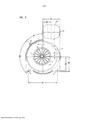
[019] A figura 1 é uma vista em perspectiva esquemática explodida de um conjunto filtro de ar de acordo com a presente divulgação.[019] Figure 1 is a schematic exploded perspective view of an air filter assembly according to the present disclosure.
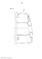
[020] A figura 2 é uma vista elevada lateral esquemática do filtro de ar representado na figura 1; na figura 2, partes selecionadas sendo mostradas em vista seccional transversal para inspeção dos detalhes do interior.[020] Figure 2 is a schematic side elevation view of the air filter shown in Figure 1; in figure 2, selected parts being shown in cross-sectional view for inspection of interior details.
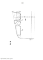
[021] A figura 3 é uma vista elevada esquemática, ampliada da extremidade de saída do conjunto representado nas figuras 1 e 2.[021] Figure 3 is an enlarged, schematic elevation view of the output end of the assembly shown in Figures 1 and 2.
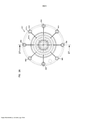
[022] A figura 4 é uma vista esquemática da extremidade exterior na direção de uma segunda tampa de extremidade fechada de um conjunto de cartucho de filtro primário das figuras 1-3.[022] Figure 4 is a schematic view of the outer end toward a second closed end cap of a primary filter cartridge assembly of figures 1-3.
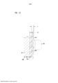
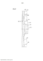
[023] A figura 5 é uma vista seccional transversal fragmentada es-quemáticatomada, no geral, ao longo da linha 5-5 da figura 4.[023] Figure 5 is a schematic fragmentary cross-sectional view taken generally along line 5-5 of Figure 4.
[024] A figura 5A é uma vista esquemática fragmentada ampliada de uma parte da superfície representada na figura 4.[024] Figure 5A is an enlarged fragmentary schematic view of a portion of the surface shown in Figure 4.
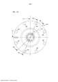
[025] A figura 6 é uma vista elevada esquemática da extremidade exterior de uma componente da proteção de acesso do conjunto das figuras 1-3.[025] Figure 6 is a schematic elevation view of the outer end of a component of the access protection of the set of figures 1-3.
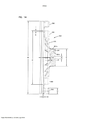
[026] A figura 7 é uma vista seccional transversal esquemática tomada ao longo da linha 7-7 da figura 6.[026] Figure 7 is a schematic cross-sectional view taken along line 7-7 of Figure 6.
[027] A figura 7A é uma vista em perspectiva ampliada esquemática fragmentada da parte selecionada da superfície interior da proteção de acesso, representada na figura 6, a ampliação sendo de uma parte da figura 1.[027] Figure 7A is an enlarged perspective schematic fragmentary view of the selected part of the interior surface of the access protection, represented in Figure 6, the enlargement being of a part of Figure 1.
[028] A figura 7B é uma vista esquemática fragmentada ampliada de uma parte selecionada da figura 7A, mostrada em vista plana.[028] Figure 7B is an enlarged fragmentary schematic view of a selected part of figure 7A, shown in plan view.
[029] A figura 8 é uma vista seccional transversal esquemática que re-presenta o encaixe entre o cartucho da figura 5 e a proteção de acesso da figura 7.[029] Figure 8 is a schematic cross-sectional view that represents the fit between the cartridge of figure 5 and the access protection of figure 7.
[030] A figura 8A é uma vista fragmentada ampliada de uma parte se- lecionada da figura 8.[030] Figure 8A is an enlarged fragmentary view of a selected portion of Figure 8.
[031] A figura 8B é uma vista explodida fragmentada esquemática ampliada correspondente à figura 8A.[031] Figure 8B is an enlarged schematic fragmentary exploded view corresponding to Figure 8A.
[032] A figura 9 é uma vista esquemática fragmentada de uma parte da figura 1.[032] Figure 9 is a schematic fragmentary view of a part of Figure 1.
[033] A figura 10 é uma vista elevada lateral esquemática da segunda modalidade de um filtro de ar de acordo com a presente divulgação; na figura 10, partes selecionadas são mostradas em vista seccional transversal para inspeção dos detalhes do interior.[033] Figure 10 is a schematic side elevation of the second embodiment of an air filter according to the present disclosure; in figure 10, selected parts are shown in cross-sectional view for inspection of interior details.
[034] A figura 11 é uma vista seccional transversal esquemática ampliada do elemento do cartucho de filtro do filtro de ar na figura 10; na figura 11, partes são mostradas em seção transversal.[034] Figure 11 is an enlarged schematic cross-sectional view of the filter cartridge element of the air filter in Figure 10; in figure 11, parts are shown in cross section.
[035] A figura 12 é uma vista esquemática fragmentada ampliada de uma parte selecionada da figura 11.[035] Figure 12 is an enlarged fragmentary schematic view of a selected portion of Figure 11.
[036] A figura 13 é uma vista esquemática da extremidade do cartucho de filtro da figura 11.[036] Figure 13 is a schematic view of the end of the filter cartridge of figure 11.
[037] A figura 14 é uma vista seccional transversal esquemática de um componente da tampa de extremidade do cartucho de filtro da figura 11 tomada ao longo da linha 14-14 da figura 13.[037] Figure 14 is a schematic cross-sectional view of a component of the filter cartridge end cap of Figure 11 taken along line 14-14 of Figure 13.
[038] A figura 15 é uma segunda vista seccional transversal esquemática do componente da tampa de extremidade com o cartucho da figura 11, a vista seccional transversal da figura 15 sendo tomada ao longo da linha 15-15 da figura 13.[038] Figure 15 is a second schematic cross-sectional view of the end cap component with the cartridge of Figure 11, the cross-sectional view of Figure 15 being taken along line 15-15 of Figure 13.
[039] A figura 16 é uma vista seccional transversal esquemática ampliada de um componente da proteção de acesso do conjunto filtro de ar da figura 10.[039] Figure 16 is an enlarged schematic cross-sectional view of a component of the access protection of the air filter assembly of Figure 10.
[040] A figura 17 é uma vista esquemática de uma superfície interna do componente da proteção de acesso da figura 16.[040] Figure 17 is a schematic view of an inner surface of the access guard component of Figure 16.
[041] A figura 18 é uma vista elevada lateral esquemática de um componente alternativo da proteção de acesso.[041] Figure 18 is a schematic side elevation view of an alternative access protection component.
[042] A figura 19 é uma vista seccional transversal esquemática do componente alternativo da proteção de acesso da figura 18.[042] Figure 19 is a schematic cross-sectional view of the alternative component of the access protection of Figure 18.
[043] A figura 20 é uma vista elevada lateral esquemática de uma mo-dalidade modificada de um filtro de ar de acordo com a presente divulgação; na figura 20, partes selecionadas sendo mostradas em vista seccional transversal para inspeção dos detalhes internos.[043] Figure 20 is a schematic side elevation view of a modified modality of an air filter in accordance with the present disclosure; in figure 20, selected parts being shown in cross-sectional view for inspection of internal details.
[044] A figura 21 é uma vista elevada lateral esquemática de um componente da proteção de acesso do conjunto da figura 20.[044] Figure 21 is a schematic side elevation of a component of the access protection of the assembly of Figure 20.
[045] A figura 22 é uma vista esquemática da extremidade externa do componente da proteção de acesso da figura 21.[045] Figure 22 is a schematic view of the outer end of the access protection component of Figure 21.
[046] A figura 23 é uma vista esquemática interna do componente da proteção de acesso da figura 21.[046] Figure 23 is an internal schematic view of the access protection component of Figure 21.
[047] A figura 24 é uma vista seccional transversal esquemática tomada ao longo da linha 24-24 da figura 22.[047] Figure 24 is a schematic cross-sectional view taken along line 24-24 of Figure 22.
[048] A figura 25 é uma vista esquemática fragmentada ampliada tomada ao longo da linha 25-25 da figura 22.[048] Figure 25 is an enlarged fragmentary schematic view taken along line 25-25 of Figure 22.
[049] A figura 26 é uma vista esquemática elevada de extremidade ampliada de um componente da tampa de extremidade fechada de um cartucho de filtro no conjunto da figura 20.[049] Figure 26 is an enlarged end elevational schematic view of a closed end cap component of a filter cartridge in the assembly of Figure 20.
[050] A figura 27 é uma vista seccional transversal esquemática ampliada do componente da tampa de extremidade da figura 26 tomada, no geral, ao longo da linha 27-27 desta.[050] Figure 27 is an enlarged schematic cross-sectional view of the end cap component of Figure 26 taken generally along line 27-27 thereof.
[051] A figura 28 é uma vista de um lado interior da tampa de extremidade das figuras 26 e 27.[051] Figure 28 is an inner side view of the end cap of Figures 26 and 27.
[052] O número de referência 1 da figura 1 indica, no geral, um conjunto filtro de ar de acordo com a presente divulgação. O conjunto filtro de ar 1 inclui um alojamento 2 com um corpo de alojamento 3 e uma proteção de acesso ou de manutenção 4. O conjunto 1 inclui um cartucho de filtro 5 removível e substituível, isto é, que pode passar por manutenção.[052] Reference number 1 of Figure 1 generally indicates an air filter assembly according to the present disclosure. The air filter assembly 1 includes a
[053] Em relação à figura 1, o alojamento 1 (em particular, o corpo de alojamento 3) inclui plataformas de montagem 8 para prisão na estrutura de um veículo ou outro equipamento no qual o conjunto filtro de ar 1 é preso para uso. Uma variedade de orientações de plataformas de montagem 8 pode ser usada nos princípios da presente divulgação. Em alguns arranjos, em vez de plataformas de montagem formadas integralmente com o corpo de alojamento, um arranjo de banda de montagem pode ser usado.[053] Referring to figure 1, housing 1 (in particular housing body 3) includes mounting
[054] No geral, o corpo de alojamento 3 compreende uma parede lateral 10 com uma primeira extremidade aberta 11 e oposta à segunda extremidade 12 com uma primeira passagem de fluxo de ar 13 até ela. No exemplo mostrado, o alojamento 2 inclui adicionalmente segunda passagem de fluxo de ar 15.[054] Overall, the
[055] Para o exemplo em particular mostrado, a passagem de fluxo de ar 13 é uma passagem de saída do fluxo de ar definida pelo tubo de saída 13a; e a passagem do fluxo de ar 15 é uma passagem de entrada de fluxo de ar definida pelo tubo de entrada 15a. Percebe-se que, para o exemplo mostrado, ambas passagens do fluxo de ar 13a, 15a ficam localizadas no corpo de aloja- mento 3. Em algumas aplicações alternativas aos princípios aqui descritos, uma das passagens do fluxo de ar, por exemplo, a passagem de entrada de fluxo de ar 15, pode ficar localizada na proteção de acesso 4.[055] For the particular example shown, the
[056] Adicionalmente, para o exemplo mostrado, cada uma das passagens do fluxo de ar 13a, 15a é uma única abertura. Entretanto, em técnicas aplicações alternativas aqui usadas, uma ou mais das passagens 13a, 15a podem ser definidas por múltiplas aberturas.[056] Additionally, for the example shown, each of the
[057] A entrada do fluxo de ar 15 fornece passagem do ar a ser filtrado para o interior do filtro de ar 1. A entrada do fluxo de ar 15 em particular representada fica posicionada para direcionar este ar através da parede lateral 10.[057] The
[058] Em operação, o cartucho do filtro de ar 5 é inserido no corpo de alojamento 3 através da extremidade aberta 11. Então, a proteção de acesso 4 é encaixada sobre a extremidade aberta 11 e o cartucho 5 para fechar a extremidade aberta 11. Em um exemplo mostrado, o alojamento 2 inclui um arranjo de fechamento 20 que compreende uma pluralidade de trincos 21. A proteção de acesso 4 é presa no lugar na extremidade do alojamento 11 pelo arranjo de fechamento 20. No arranjo filtro de ar de exemplo 1 em particular representado, o arranjo de fechamento 20 (que compreende trincos 21) é montado na proteção de acesso 4 para encaixe selecionado no corpo de alojamento 3. Percebe-se que, em algumas aplicações alternativas das técnicas aqui descritas, os trincos 21 podem ser posicionados no corpo de alojamento 3 para encaixe na proteção de acesso 4.[058] In operation, the
[059] Ainda em relação à figura 1, o cartucho 5 compreende, no geral, um meio filtrante 25 que se estende entre as primeira e segunda tampas de extremidade opostas 26, 27. Em um arranjo típico, a tampa de extremidade 27 será uma tampa de extremidade fechada, isto é, ela não tem aberturas através de si, através das quais o ar pode fluir. Entretanto, tipicamente, a tampa de ex-tremidade 26 será uma tampa de extremidade aberta, incluindo abertura do fluxo de ar central aberta 29 através de si e ao redor da qual o meio filtrante 25 se estende.[059] Still referring to Figure 1, the
[060] O meio filtrante 25 pode incluir o meio 25a selecionado a partir de uma variedade de tipos de meio. Por exemplo, o meio filtrante 25 pode compreender meio pregueado, embora alternativas sejam possíveis. Em muitos arranjos, o meio filtrante 25 será fornecido com um ou mais de revestimentos de suporte interno e externo para o meio 25a. Por exemplo, tais revestimentos de suporte podem compreender arranjos de plástico, arranjos de metal expandido ou arranjos de metal poroso.[060]
[061] Em um típico meio filtrante 25, o meio 25a circunda e define um interior aberto 30. No geral, a abertura 29, na primeira tampa de extremidade 26 fica em relacionamento de fluxo de ar com o interior aberto 30. Neste contexto, por "relacionamento de fluxo de ar", e variantes deste, entende-se que a abertura 29 se abre para o interior 30, e ar pode fluir entre os dois sem passagematravés do meio filtrante 25.[061] In a
[062] Percebe-se que as técnicas aqui descritas podem ser aplicadas e usadas com, além do cartucho de filtro primário 5, um cartucho de filtro secundário ou de segurança. O exemplo representado nas figuras não mostra um cartucho de segurança. Entretanto, um cartucho de segurança pode ser posicionado internamente em relação a um interior 30. Isto exigirá que o ar, apesar do meio 25a, passe através do cartucho de segurança antes de sair do alojamento 2 através da saída de fluxo de ar 13.[062] It is understood that the techniques described here can be applied and used with, in addition to the
[063] Um meio filtrante 25 típico pode ser fornecido em uma variedade de formas, por exemplo, ele pode ser cilíndrico ou ter um afunilamento cônico até ele. Quando o meio filtrante 25 tiver um afunilamento cônico, em uma aplicação típica, o afunilamento será para baixo (para dentro) da tampa de extremidade 26, na direção da tampa de extremidade 27. O ângulo cônico típico (afunilamento para dentro), quando usado, será pelo menos cerca de 0,5 grau, usualmente, pelo menos 1,0 grau e, frequentemente, na faixa de 1,0 - 6,0 °, inclusive, embora alternativas sejam possíveis.[063] A
[064] O conjunto filtro de ar 1 em particular representado é configurado para fluxo "direto". Neste contexto, por "direto" entende-se que o ar, no geral, durante a filtragem, flui através do meio filtrante 25, do exterior para o interior aberto 30 (algumas vezes referido como fluxo de fora para dentro). Assim, quando o conjunto filtro de ar 1 for operado, o ar a ser filtrado flui através da entrada 15, para o interior de um espaço anular 35 (figura 2) no alojamento 2 (e proteção de acesso 3) que se estende ao redor do cartucho de filtro 5. Então, o ar passa através do meio filtrante 25 até o interior aberto 30. Então, o ar passa a partir do cartucho 5, através da extremidade aberta 29, e deixa o filtro de ar através da saída do fluxo de ar de entrada 13.[064] The particular air filter assembly 1 depicted is configured for "direct" flow. In this context, by "direct" it is meant that the air, in general, during filtration, flows through the filter medium 25 from the outside to the open interior 30 (sometimes referred to as outside-in flow). Thus, when the air filter assembly 1 is operated, the air to be filtered flows through
[065] Naqueles casos em que um filtro segurança é usado, o ar proveniente do cartucho de filtro principal 5 passará através do filtro segurança, depois da passagem através do cartucho 5 e antes de sair através da saída 13.[065] In those cases where a safety filter is used, the air coming from the
[066] Muitos dos princípios aqui descritos podem ser aplicados com arranjos de "fluxo invertido" ou "fluxo de dentro para fora", nos quais o ar, durante a filtragem, passa do interior 30, através do meio filtrante 25, até um local exterior.[066] Many of the principles described here can be applied with "inverted flow" or "inside-out flow" arrangements in which the air, during filtration, passes from the interior 30, through the
[067] Em operação típica, o corpo de alojamento 3 fica preso no equi-pamento, tal como um caminhão, com o qual o filtro de ar 1 é usado, e a proteção de acesso 4 é separável do corpo principal 3, para acesso de manutenção ao cartucho 5.[067] In typical operation,
[068] No geral, o cartucho 5 inclui um arranjo de vedação do alojamento 38 na tampa de extremidade 26, vedado no interior de uma parte do alojamento 2, quando o cartucho 5 for instalado.[068] Overall,
[069] Em relação à figura 1, percebe-se que o alojamento 2 (que compreende o corpo 3 e a proteção de acesso 4) é configurado para cada um dos dois componentes a ser moldados a partir de um plástico, por exemplo, um, polipropileno reforçado com vidro. Os princípios aqui descritos são particularmente adaptados para arranjos de plástico, entretanto, eles podem ser utilizados quando um mais dos componentes 3,4, ou partes dos componentes 3,4 compreenderem folha de metal.[069] In relation to figure 1, it is noticed that the housing 2 (comprising the
[070] Agora, atenção é direcionada para a figura 2. Na figura 2, uma vista elevada lateral do conjunto filtro de ar 1 é representada. Na figura 2, o conjunto filtro de ar 1 é mostrado com a proteção de acesso 4 presa no corpo de alojamento 3. Também na figura 2, uma parte do conjunto filtro de ar 1 é representada em seção transversal, de forma que detalhes internos possam ser visualizados. Em relação à figura 2, o espaço anular do fluxo de ar 35 ao redor do cartucho 5 é visualizável. O espaço anular do fluxo de ar 35 de exemplo se estende completamente de forma radial ao redor do cartucho 5, para a distribuição do ar a ser filtrado ao redor do cartucho 5 durante a operação.[070] Now, attention is directed to figure 2. In figure 2, a side elevation view of the air filter assembly 1 is represented. In figure 2, the air filter assembly 1 is shown with the access guard 4 secured to the
[071] Em relação à figura 2, a tampa de extremidade 26 é visualizável em seção transversal. No geral, o cartucho 5 inclui um arranjo de vedação do alojamento 38 na tampa de extremidade 26, vedando uma parte no alojamento 2 quando o cartucho 5 for instalado. A tampa de extremidade 26, para o exemploespecífico mostrado, define uma parte de vedação radial 38a ao redor da abertura 29. No geral, a parte de vedação radial 38a é orientada para formar uma vedação radial direcionada para dentro em relação a uma superfície externa do tubo 39, quando o cartucho 5 for instalado. Tais arranjos de vedação radial direcionada para dentro são descritos, por exemplo, em US 5.547.480, 6.652.614, WO 2007/022171, 6.039.778 e 6.955.701. Percebe-se que uma variedade de locais e configurações alternativos dos arranjos de vedação do alojamento pode ser usada no cartucho 5 e no alojamento 3, de acordo com a presente divulgação. Por exemplo, vedações radiais direcionadas para fora podem ser usadas, embora alternativas ainda adicionais sejam possíveis.[071] With respect to figure 2, the
[072] Uma variedade de arranjos específicos pode ser utilizada para formar a parte de vedação radial direcionada para dentro 38a. Em um arranjo típico, a tampa de extremidade 26 será uma tampa de extremidade moldada no lugar que compreende um poliuretano em espuma, tais como aqueles descritos em US 6.955.701. Tais materiais podem ser formados durante o processo de moldagem para definir a parte de vedação radial 38a na abertura 29.[072] A variety of specific arrangements can be utilized to form the inwardly directed radial seal portion 38a. In a typical arrangement, the
[073] Ainda em relação à figura 2, percebe-se que, para o conjunto filtro de ar 1 de exemplo em particular representado, o cartucho 5 é suficientemente grande para se projetar para o interior da proteção de acesso ou de manutenção 4. Por exemplo, em relação à figura 2, a parte 5x do cartucho 5 se estende além do corpo de alojamento 3 para o interior da proteção de acesso 4. Em um exemplo típico, esta extensão será de pelo menos 30 mm e, tipicamente, na faixa de 40-75 mm, inclusive, comprimento do cartucho entre as tampas de extremidade 26 e 27. Entretanto, os princípios aqui descritos podem ser aplicados em arranjos nos quais uma linha de separação (indicada em 40 na figura 2), entre a proteção de acesso 4 e o corpo de alojamento 3, fica localizadaalém da tampa de extremidade 27, em uma direção para longe da tampa de extremidade 26.[073] Still in relation to figure 2, it can be seen that, for the air filter assembly 1 of the particular example shown, the
[074] Em relação à figura 2, pode-se ver que o cartucho do filtro de ar 5, quando instalado, fica preso na tampa de extremidade 26 ao redor tubo 39, e é suportado neste local. Na extremidade oposta, isto é, a extremidade do cartucho em que a tampa de extremidade 27 fica localizada, o cartucho 5 deve ser suportado, ou o cartucho do filtro de ar 5 será de cantiléver em relação ao tubo do alojamento. O suporte no cartucho 5, a partir do alojamento 2 na tampa de extremidade 27, que impede níveis indesejáveis de movimento em cantiléver, será referido como suporte "de cantiléver"ou de "extremidade cantiléver"ou por termos similares. Aqui, o suporte de cantiléver é fornecido na tampa de extremidade 27, pelo encaixe entre uma parte da proteção de acesso 4 e uma parte da tampa de extremidade ou da proteção 27, da forma discutida a seguir.[074] Referring to figure 2, it can be seen that the
[075] Em termos mais gerais, um arranjo projeção / receptor é fornecido com um elemento na tampa de extremidade 27 e um outro elemento na proteção de acesso 4, fornecendo um encaixe de uma maneira que inibe o movimento em cantiléver de cartucho 5 na tampa de extremidade 27.[075] More generally, a projection/receiver arrangement is provided with an element in the
[076] Em relação à figura 2, o meio 25a pode ser visto com extremidades opostas 25b, 25c, a extremidade 25b sendo adjacente à tampa de extremidade 27 e a extremidade 25c sendo adjacente à tampa de extremidade 26. O meio 25a e, assim, o cartucho 5, são suportados na extremidade 25c pela inserção de tubo 39 na tampa de extremidade 26. Entretanto, a extremidade 25b, remota da extremidade 25c é de cantiléver. Aqui, entende-se que "movimento em cantiléver"e variantes deste diz respeito ao movimento (não rotativo) que pode ocorrer na extremidade 25b, remota do tubo 39, se a tampa de extremidade 27 não for apropriadamente suportada. O movimento em particular referenciado em relação ao movimento em cantiléver, é um movimento vibracional, isto é, não é um movimento rotativo. Então, movimento em cantiléver será mo- vimento para cima e para baixo da extremidade do meio 25b, ou movimento contra e a favor da extremidade do meio 25b, ou alguma combinação deste.[076] Referring to Figure 2, the middle 25a can be seen with
[077] Então, em termos gerais, o suporte de cantiléver é o suporte de cartucho 5 contra os níveis indesejáveis de movimento em cantiléver. Isto é, o esforço não é necessariamente para impedir algum movimento vibracional, mas somente para inibir o movimento além de algum nível aceitável.[077] So, in general terms, cantilever holder is
[078] O encaixe na tampa de extremidade 26, para o conjunto filtro de ar de exemplo representado, é uma vedação radial circular direcionada para dentro. Assim, ela é radialmente simétrica e sujeita à rotação em potencial do cartucho 5 ao redor do tubo 39. O suporte na tampa de extremidade 27, através do encaixe entre a tampa de extremidade 27 e a proteção de acesso 4 (da forma aqui descrita), também inibe o movimento rotativo relativo do cartucho 5 em relação à proteção de acesso 4, uma vez instalado. Já que a proteção de acesso 4 fica presa no lugar no corpo 3, isto inibe a rotação da tampa de extremidade 26 ao redor do tubo 39, uma vez que cartucho 5 for instalado.[078] The fitting in the
[079] Um encaixe entre a proteção de acesso 4 e o cartucho 5, que inibe níveis indesejáveis de movimento rotativo um em relação ao outro, será aqui referido como encaixe "não rotativo". Novamente, já que, no geral, a proteção de acesso 4 fica presa de forma não rotativa no lugar, no corpo de alojamento 3, pelo arranjo 20, um encaixe não rotativo entre a proteção de acesso 4 e o cartucho 5 inibe o cartucho 5 de rotacionar ao redor do tubo 39 uma vez instalado.[079] A fit between the access guard 4 and the
[080] Ainda em relação à figura 2, a proteção de acesso 4 inclui um orifício de ejeção 45. Água e/ou poeira podem ser ejetadas através do orifício 45, durante a operação. Tipicamente, o filtro de ar 1 é instalado com o orifício de ejeção de poeira e água 45 angulado para baixo.[080] Still referring to figure 2, access guard 4 includes an ejection hole 45. Water and/or dust may be ejected through hole 45 during operation. Typically, the air filter 1 is installed with the dust and water ejection hole 45 angled downwards.
[081] Novamente em relação à figura 2, percebe-se que a proteção de acesso 4 não inclui nenhuma projeção ou anteparo que se estende axialmente a partir dela (na direção da extremidade 12 do corpo 3) e espaçado para dentro a partir do lado 4x, que também circunda o cartucho 5. A ausência de um anteparo como este facilita o fluxo de ar ao redor da extremidade 27 e a direção da poeira e da água na direção da saída de evacuação 45. Isto também significa que nenhuma parte do meio em 25 é coberta pelo fluxo ao redor deste.[081] Again with respect to figure 2, it is noted that the access guard 4 does not include any projection or shield extending axially therefrom (towards
[082] Alternativamente declarado, a proteção de acesso 4 inclui um aro externo 4x que encaixa no corpo 3 quando a proteção de acesso 4 for montada. A seção do aro 4x da figura 2 é a única parte da proteção de acesso 4, no exemplo mostrado, que circunda uma parte do lado externo do meio filtrante 25.[082] Alternatively stated, Access Guard 4 includes a 4x outer rim that fits into
[083] Ainda em relação à figura 2, também percebe-se que, para o cartucho 5 de exemplo em particular representado, nenhuma parte de tampa de extremidade 27 se projeta para o interior 30 em uma quantidade substancial; uma quantidade substancial neste contexto significando uma projeção de 10 mm ou mais. Assim, para o exemplo específico mostrado não há estrutura se projetando 10 mm para o interior do cartucho interior 30 ao redor do qual o meio filtrante 25 se estende.[083] Still referring to Figure 2, it is also noted that, for the
[084] Na figura 2, as dimensões de exemplo para o arranjo filtro de ar de exemplo representado são fornecidas como segue: AA = 31,9 mm; AB = 52 °; AC = 582 mm; AD = 190 mm; AE = 263,6 mm; AF = 184 mm; AH = 366 mm; AG = 182 mm; AI = 34 mm; AJ = 60 mm; AM = 280 mm; AK = 50,5 mm e AL = 54 mm. Outras dimensões podem ser estimadas a partir da escala.[084] In Figure 2, the example dimensions for the example air filter arrangement depicted are given as follows: AA = 31.9 mm; AB = 52°; AC = 582 mm; AD = 190 mm; EA = 263.6 mm; AF = 184 mm; HA = 366 mm; AG = 182 mm; AI=34mm; AJ = 60 mm; AM = 280 mm; AK = 50.5 mm and AL = 54 mm. Other dimensions can be estimated from the scale.
[085] Certamente, as dimensões são meramente propostas para indicar um arranjo de exemplo usável. Dimensões e arranjos alternativos podem ser utilizados com os princípios de acordo com a presente divulgação.[085] Of course, dimensions are merely proposed to indicate a usable example arrangement. Alternative dimensions and arrangements may be used with the principles in accordance with the present disclosure.
[086] A atenção é agora direcionada para a figura 3. Na figura 3, uma vista elevada de extremidade do conjunto filtro de ar 1 é representada. Na figura 3, a vista é direcionada para a extremidade do alojamento 12 e a saída 13. Aqui, o arranjo de plataforma 8 para prender o alojamento 2 no lugar no equipamentotambém é visualizável.[086] Attention is now directed to figure 3. In figure 3, an end elevation view of the air filter assembly 1 is represented. In figure 3, the view is directed towards the end of the
[087] Na figura 3, pode-se visualizar, através do tubo 13, o interior 30 do cartucho 5.[087] In figure 3, one can see, through
[088] Na figura 3, dimensões de exemplo do conjunto filtro de ar 1 das figuras 1-3 são indicadas como segue: BA = 180 mm; BB = 83,5 mm; BC = 45 °; BE = 90 °; BK = 300 mm; BG = 141 mm, BH = 153 mm, BD =D 10 mm e BF = 5 mm.[088] In figure 3, example dimensions of the air filter assembly 1 of figures 1-3 are indicated as follows: BA = 180 mm; BB = 83.5 mm; BC = 45°; BE = 90°; BK=300mm; BG = 141 mm, BH = 153 mm, BD =D 10 mm and BF = 5 mm.
[089] Novamente, em relação à figura 2, para o cartucho 5 em particular representado, a tampa de extremidade 27 compreende uma tampa de extremidade fechada, sem abertura através de si, e se estendendo através da extremidade 25b do meio filtrante 25; uma extremidade oposta 25c do meio filtrante 25 sendo embutida na tampa de extremidade 26. Para um arranjo típico, embora alternativas sejam possíveis, a tampa de extremidade 27 compreenderá uma parte pré-formada, na qual o meio filtrante 25 é envasado com um material adesivo ou de vedação. Tipicamente, a tampa de extremidade 27 compreenderá um material plástico pré-formado, tal como um ABS envasado com um poliuretano duro.[089] Again, referring to Figure 2, for the
[090] Alternativamente declarado (e da forma supradiscutida), em uma aplicação típica, a tampa de extremidade 26 será moldada no lugar a partir de uma resina apropriada para formar uma estrutura macia e comprimível, isto é, o meio filtrante 25 será inserido no material de tampa de extremidade 26 à medi- da que o material endurece, e é moldado na forma desenhada. Embora isto não seja exigido, isto será típico para todas as aplicações dos presentes princípios.[090] Alternatively stated (and as discussed above), in a typical application, the
[091] Ao contrário, tipicamente, primeiro, a tampa de extremidade 27 é moldada a partir de um material apropriado para formar uma parte de plástico rígido e, então, é anexada na extremidade 25b, por exemplo, com um adesivo de envasamento. Embora alternativas sejam possíveis, isto será típico e conveniente.[091] In contrast, typically,
[092] Na figura 4, é fornecida uma vista de extremidade do cartucho 5. A vista de extremidade do cartucho 5 é tomada direcionada para a tampa de extremidade 27. Assim, a superfície estrutural visualizável na figura 4 é a superfície exterior 27x da tampa de extremidade 27 da figura 2.[092] In figure 4, an end view of
[093] Na figura 4, dimensões e ângulos de exemplo são como segue: CA = 45 °; CB = 22,5 °; CC = 3,3 mm de raio; CD = 5,4 mm de raio; CF = 16,8 mm de raio; CG = 3,5 mm de raio; Cl = 41,6 mm de diâmetro e CH = 87 mm de diâmetro.[093] In figure 4, example dimensions and angles are as follows: CA = 45°; CB=22.5°; CC = 3.3 mm radius; CD=5.4mm radius; CF = 16.8 mm radius; CG = 3.5 mm radius; Cl = 41.6 mm in diameter and CH = 87 mm in diameter.
[094] Na figura 5, uma vista seccional transversal é tomada ao longo da linha 5-5 da figura 4. Aqui, tanto a superfície exterior 27x quanto a superfície interior 27i são visualizáveis na parte de extremidade 27.[094] In figure 5, a cross-sectional view is taken along line 5-5 of figure 4. Here, both the
[095] A figura 5 é uma vista seccional transversal fragmentada. A ex-tremidade 25b do meio filtrante 25 é visualizável na vista fragmentada.[095] Figure 5 is a fragmentary cross-sectional view.
[096] Em relação à figura 5, a tampa de extremidade 27 inclui um aro externo 51. O aro externo 51 encaixa ao redor (circunscreve) o meio filtrante 25. Ao longo da superfície interior 27i, a parte de extremidade 27 inclui uma nervura 53. A nervura 53 opera como um separador do meio, durante a montagem. Isto é, quando o meio filtrante 25 for encaixado na extremidade 51, o meio filtrante 25 encosta na nervura 53 durante o envase.[096] Referring to Figure 5, the
[097] A projeção 55 forma um interior de um anel de contenção para o meio filtrante 25 e o material de envase (a contenção exterior fornecida pelo aro 51). Isto é, durante a montagem do cartucho 5, o meio filtrante 25 é posicionado com a extremidade 25b deste orientada entre o aro 51 e a projeção interna 55. U, material de envase fica posicionado neste local para prender a parte de extremidade 27 no lugar no meio filtrante 25. Nervura de separação 53 garantirá que o material de vedação ou de envase possa vedar entre a extremidade 27b do meio filtrante 25 e a parte de anel do perímetro 58 da superfície interna 27i.[097] The
[098] Previamente, foi discutido que em um arranjo típico, embora al-ternativas sejam possíveis, não há projeção se estendendo substancialmente para o interior 30 a partir da tampa de extremidade 27. Pode-se ver que a projeção 55 é relativamente pequena e não se estende 10 mm para o interior 30.[098] Previously, it was discussed that in a typical arrangement, although alternatives are possible, there is no projection extending substantially inwardly 30 from the
[099] Então, em relação à figura 4, a superfície da extremidade 27x inclui uma seção de anel externo 65 em sobreposição com o meio filtrante 25 no cartucho 5. A superfície externa 27x inclui adicionalmente uma parte central interna 66 circundada pelo anel externo 65. A parte central 66 no cartucho 5 da figura 2 não fica em sobreposição axial no meio filtrante 25, mas, em vez disto, sobrepõe a região interior 30 que é circundada pelo meio filtrante 25.[099] So, with reference to Figure 4, the
[0100] Em relação à figura 4, a região 65 e o aro 51 podem ser visualizados com uma orientação circular ao redor do centro 27z da tampa de extremidade 27.[0100] With respect to figure 4, the region 65 and the
[0101] No geral, aqui, um arranjo projeção / receptor é fornecido para encaixe entre o cartucho 5 e a proteção de acesso 4. Em particular, o arranjo projeção / receptor representado fornece o encaixe entre a tampa de extremi- dade do cartucho 27 e a proteção de acesso 4 de uma maneira que suporta o cartucho 5 contra níveis indesejáveis de movimento em cantiléver na tampa de extremidade 27 e inibe o movimento rotativo relativo entre o cartucho 5 e a proteção de acesso 4 (e, assim, entre o cartucho 5 e o tubo de saída 39 no conjunto filtro de ar 1).[0101] In general, here, a projection/receiver arrangement is provided for engagement between
[0102] Em termos gerais, o arranjo projeção / receptor inclui um elemento de projeção em um primeiro do cartucho 5 e da proteção de acesso 4 e o elemento receptor em um outro da proteção de acesso 4 e do cartucho 5. Para o exemplo em particular representado, o arranjo projeção / receptor inclui um arranjo do elemento de projeção (primeiro) no cartucho 5, e um arranjo do elemento receptor (segundo) na proteção de acesso 4. Entretanto, alternativas são possíveis.[0102] In general terms, the projection/receiver arrangement includes a projection element in a first one of the
[0103] Em relação à figura 5, a parte central 66 da superfície externa da tampa de extremidade 27x inclui o arranjo de projeção 70. Em termos gerais, o arranjo de projeção 70 se projeta a partir de um restante da tampa de extremidade 27, em uma direção para longe da extremidade 256 do meio filtrante 25, isto é, em uma direção, no geral, para longe da tampa de extremidade oposta 26. A distância da projeção 70 indicada na dimensão CJ da figura 5 é, tipicamente, pelo menos 10 mm, usualmente, pelo menos 15 mm e, frequentemente, na faixa de 20 a 40 mm. No exemplo representado, a dimensão CJ é 25 mm.[0103] Referring to Figure 5, the central portion 66 of the outer surface of the
[0104] A direção da projeção 70 é, no geral, axial, isto é, na direção correspondente à direção geral do eixo geométrico central X da figura 2 e para longe da tampa de extremidade 26. Neste contexto, por "axial", não entende-se que as projeções das superfícies externa e interna 70o, 70i da projeção 70 são, necessariamente, precisamente paralelas ao eixo geométrico X. De fato, cada uma pode ser angulada um tanto a partir do eixo geométrico X.[0104] The direction of
[0105] Tipicamente, a superfície externa 70o inclina para dentro ao longo de uma direção de extensão a partir de uma região adjacente da tampa de extremidade 27, e a superfície interna 70i inclina para fora ao longo da sua direção de extensão a partir de uma região adjacente da tampa de extremidade 27. Este ângulo de inclinação para dentro da superfície 70o é indicado em CK e, no geral, fica na faixa de 3 - 7 °, inclusive. O ângulo correspondente da superfície de extensão para fora 70i é indicado em CM e, tipicamente, fica na faixa de 3 - 7 °, inclusive. No exemplo representado na figura 5, CK e CM são, cada qual, 5,6 °.[0105] Typically, the outer surface 70o slopes inward along an extension direction from an adjacent region of the
[0106] Ângulos em relação às superfícies 70o, 70i do tipo indicado fornecem a projeção 70 com uma ponta axialmente mais externa 70t, que é um tanto estreitada em relação a uma região base 70b de projeção 70. Uma ponta um tanto quanto estreita 70t facilita a inserção em um arranjo receptor descrito a seguir na proteção de acesso 4.[0106] Angles to
[0107] A atenção é agora direcionada para a figura 5A, uma vista plana esquemática fragmentada do arranjo de projeção 70 tomada em uma direção geral da seta 80 da figura 5. Na figura 5, percebe-se que a representação esquemática fornece a forma de projeção 70 geral da vista plana, e não considera uma inclinação para os lados 70o, 70i.[0107] Attention is now directed to figure 5A, a fragmentary schematic plan view of the
[0108] Em relação à figura 5A, embora alternativas sejam possíveis, o arranjo de projeção 70 em particular representado compreende uma parede contínua 84. Neste contexto, por "contínuo"entende-se que não há folgas na parede 84 em relação à extensão ao redor do perímetro definido pela parede 84, isto é, ao redor do centro 27z.[0108] With reference to Figure 5A, although alternatives are possible, the
[0109] Também, embora alternativas sejam possíveis, a parede 84 é completamente "fechada". Por isto, entende-se que a parede 84 não inclui nenhuma abertura através de si em sua extensão contínua.[0109] Also, although alternatives are possible, wall 84 is completely "closed". By this, it is understood that the wall 84 does not include any opening therethrough in its continuous extension.
[0110] Em relação à figura 5, a seção transversal, também percebe-se que para o exemplo em particular representado, a projeção 70 é "sólida"por toda a parte, interface, não tem um interior oco entre as superfícies 70o, 70i. Isto será típico e conveniente.[0110] In relation to Figure 5, the cross section, it is also noted that for the particular example shown, the
[0111] No geral, o arranjo de projeção 70 tem uma maior dimensão externa mínima através de si, correspondente à dimensão D1 da figura 5A, de pelo menos 35 mm e, frequentemente, na faixa de 40 a 100 mm. Um motivo para isto é que ele facilita o encaixe na proteção de acesso 4 em um arranjo preferido típico.[0111] Overall, the
[0112] A parede 84 em particular representada circunda uma seção da superfície interior aberta e rebaixada 85. Tipicamente, esta seção tem um acesso da menor dimensão interna, mostrado em D2, de pelo menos 15 mm, tipicamente, pelo menos 20 mm e, frequentemente, na faixa de 30 a 90 mm.[0112] The particular wall 84 depicted surrounds an open and recessed inner surface section 85. Typically, this section has an accession of the smallest internal dimension, shown at D2, of at least 15 mm, typically at least 20 mm, and, often in the range of 30 to 90 mm.
[0113] Tipicamente, a projeção 70 é configurada ao redor do centro 27z, de maneira tal que o maior dimensão mínima através de si, indicada em D1, possa ser medida em pelo menos duas direções em ângulos retos um em relação ao outro, isto é, D1 indicado na figura 5a também indicará uma maior dimensão mínima em uma direção perpendicular à linha D1. Além do mais, tipicamente, a configuração da projeção 70 é de maneira tal que a menor dimensão interior através de si, indicada em D2, seja satisfeita em duas direções, a primeiro direção sendo, por exemplo, da forma indicada na linha D2, e uma segundadimensão tomada perpendicular à primeira dimensão.[0113] Typically, the
[0114] Tipicamente, a projeção 70 tem uma profundidade de extensão a partir da sua ponta 70t, em uma distância de pelo menos 6 mm (e, tipicamen- te, pelo menos 12 mm) na qual a espessura da projeção 70 não exceda 10 mm, mas, tipicamente, é de pelo menos 4 mm (descontando o afunilamento na ponta extrema). Por exemplo, esta será uma largura entre as paredes 70i, 70o, que se estende para dentro da ponta 70t pelo menos em uma profundidade de 25 % e, tipicamente, pelo menos 35 % de sua extensão de projeção. Certamente,próximo da base 70b da figura 5, a projeção 70 pode espessar (ampliar) um tanto.[0114] Typically,
[0115] A parede contínua fechada 84 em particular representada tem uma superfície externa em serpentina 88 e uma superfície interna em serpentina 89, correspondentes às superfícies 70o, 70i, respectivamente. Por "serpentina", em conjunto com a superfície externa 88, entende-se que a extensão ao redor do centro 27z, a superfície externa 88 não define uma série de linhas retas ou mesmo um círculo, mas, em vez disto, uma série de curvas internas e externas alternadas. Para o exemplo mostrado, a superfície em serpentina 88 compreende uma pluralidade de seções convexas radialmente voltadas para fora 88c e uma pluralidade de seções côncavas radialmente voltadas para fora 88d, alternando uma com a outra.[0115] The particular closed continuous wall 84 shown has a serpentine outer surface 88 and a serpentine inner surface 89, corresponding to
[0116] Em relação à superfície externa 88, entende-se que a referência a uma "seção convexa radialmente voltada para fora 88c" diz respeito a uma seção de superfície 88 que curva para fora, e entende-se que a referência a "seções côncavas radialmente voltadas para fora 88d" diz respeito a uma seção de superfície 88 que curva para dentro.[0116] In relation to the outer surface 88, the reference to a "radically outwardly facing
[0117] Analogamente, superfície interna radialmente voltada para dentro 89 também é em serpentina, compreendendo uma pluralidade de seções convexas radialmente voltadas para dentro 89c e seções côncavas radialmente voltadas para dentro 89d, alternando em uma relação à outra, à medida que a superfície interna 89 se estende ao redor do centro 27z. Para o exemplo repre-sentado, cada seção côncava 89d da superfície interna 89 corresponde com uma seção convexa 88c da superfície externa 88, e se alinha radialmente com ela, e cada seção convexa 89c de superfície interna 89 é radialmente alinhada com a seção côncava 89d da superfície externa 88.[0117] Similarly, radially inwardly facing inner surface 89 is also serpentine, comprising a plurality of radially inwardly facing
[0118] Para o exemplo em particular mostrado, a parede 84 define, em cada uma da superfície externa 88 e da superfície interna 89, oito seções côncavas e oito seções convexas. Adicionalmente: (a) uma curvatura de cada seção convexa 88c da superfície 88 é a mesma de cada outra seção convexa 88c na superfície 88 e (b) uma curvatura de cada seção côncava 88c é a mesma de cada outra côncava 88d. O mesmo é verdade para cada seção de proteção 89c e cada seção côncava 89d. O resultado é uma forma de “pétala” regular na projeção 70. Neste contexto, pelo termo "pétala"entende-se que, quando visualizada na vista plana, a projeção 70 pode ser vista com uma pluralidade de pétalas se projetando para fora, isto é, seções curvas. Neste contexto, pelo termo "regular" entende-se que cada pétala que se projeta para fora tem a mesma forma de cada outra pétala que se projeta para fora. Em relação à figura 5A, também percebe-se que o centro de cada seção convexa 88c na superfície externa 88, para o exemplo mostrado, pode ser visto definindo um vértice de uma forma octogonal, indicado em linhas tracejadas em 95. Adicionalmente, cada ponto central de cada seção côncava 89c na superfície 89 pode ser visto definindo um ponto central em um lado de um octógono internamente posicionado representado em linhas tracejadas em 96. Os octógonos 95, 96 ficam radialmente alinhados, um espaçado em relação ao outro.[0118] For the particular example shown, wall 84 defines, on each of the outer surface 88 and the inner surface 89, eight concave sections and eight convex sections. Additionally: (a) a curvature of each
[0119] Em termos mais gerais, a projeção em serpentina 70 compreende uma pluralidade de seções de pétala convexas para fora e seções cônca- vas para dentro, fornecendo uma extensão em serpentina da projeção da parede 70 ao redor do centro 27c.[0119] In more general terms, the
[0120] Tipicamente, pelos motivos discutidos a seguir, a curvatura de cada seção convexa direcionada para fora 89c é tal como para ter um raio de curvatura menor que uma curvatura hipotética de uma seção como esta se direcionada em um círculo centralizado no centro 27z, ou nele posicionado. Isto fica aparente em relação à figura 4 e comparando a curvatura do círculo C1 com a curvatura das seções convexas externas 88c.[0120] Typically, for the reasons discussed below, the curvature of each convex section directed outward 89c is such as to have a radius of curvature smaller than a hypothetical curvature of a section like this if directed in a circle centered on the center 27z, or positioned on it. This is apparent from Figure 4 and comparing the curvature of circle C1 with the curvature of the outer
[0121] Em relação à figura 5, as dimensões indicadas são como seguir: da forma supradiscutida, CJ = 25 mm; CK = 5,6 ° e CM = 5,6 °. Além do mais, CL = 4 mm de raio e CN = 5 mm de raio.[0121] In relation to figure 5, the dimensions indicated are as follows: as discussed above, CJ = 25 mm; CK = 5.6 ° and CM = 5.6 °. Furthermore, CL = 4 mm radius and CN = 5 mm radius.
[0122] A atenção é agora direcionada para as figuras 6 e 7, nas quais as partes de proteção de acesso 4 são visualizáveis. Percebe-se que nas figuras 6 e 7, a proteção de acesso 4 é representada sem o arranjo de fechamento 20, para conveniência.[0122] Attention is now directed to figures 6 and 7, in which the access protection parts 4 are viewable. It can be seen that in figures 6 and 7, the access protection 4 is shown without the closing arrangement 20, for convenience.
[0123] Em relação à figura 6, no geral, a vista da proteção de acesso 4 representada é na direção da superfície exterior 4y. Na figura 7, uma vista seccional transversal tomada ao longo da linha 7-7 da figura 6 é visualizável.[0123] With respect to figure 6, in general, the view of the access guard 4 represented is in the direction of the outer surface 4y. In figure 7, a cross-sectional view taken along line 7-7 of figure 6 is viewable.
[0124] Em relação à figura 7, no geral, a proteção de acesso 4 inclui a parede de extremidade 100 e a parede lateral 101, a parede lateral 101 correspondenteà parede lateral 4x da figura 2. A parede lateral 101 inclui a extremidade aberta 101a posicionada e dimensionada para encaixe no corpo de alojamento 3 da figura 1. A parede lateral 101, para o exemplo mostrado, é dimensionada para circundar uma parte de cartucho 5 durante a montagem. A seção central 100 é uma seção de extremidade central da proteção de acesso 4 que inclui o orifício ejetor de água / poeira 45. Em uso, tipicamente, o orifício 45 será fornecido com um elemento de válvula.[0124] Referring to figure 7, in general, access guard 4 includes
[0125] Ainda em relação à figura 7, a proteção de acesso 4 inclui uma superfície interior 4i com uma região central 100i. A região central 100i inclui um segundo elemento 105 de um arranjo projeção / receptor. O segundo elemento do arranjo projeção / receptor 105 é dimensionado, configurado e posicionado para encaixe seletivo em um primeiro elemento de um arranjo projeção / receptor no cartucho 5.[0125] Still referring to figure 7, the access protection 4 includes an
[0126] Da forma discutida até aqui, no conjunto filtro de ar 1 em particular, o cartucho 5 inclui uma projeção 70 de um arranjo projeção / receptor. Portanto, a proteção de acesso 4 inclui um elemento receptor 110 posicionado para encaixe no elemento de projeção 70.[0126] As discussed so far, in the air filter assembly 1 in particular, the
[0127] Em relação à figura 7, o elemento receptor 110 define uma ranhura receptora 111 na superfície interior da proteção 4i. No geral, a ranhura receptora 111 se estende ao redor de um eixo geométrico central Y na proteção de acesso 4. Percebe-se que, para o exemplo em particular, a ranhura 111 não é centralizada ao redor da linha Y, mas, em vez disto, é excentricamente posicionada em relação a ela.[0127] With respect to figure 7, the receiving
[0128] Na figura 7A, é representada uma vista em perspectiva frag-mentadaesquemática da ranhura receptora 111. A ranhura 111 da figura 7A é representada em uma vista correspondente a uma parte ampliada da figura 1.[0128] In figure 7A, a schematic fragmented perspective view of the receiving
[0129] Em relação à figura 7A, a ranhura receptora 111 é definida entre uma parede externa 112 e uma parede interna 113. A ranhura receptora 111 de exemplo representada é contínua. Neste contexto, por "contínuo", entende-se que, para o exemplo em particular representado, a ranhura 111 se estende ao redor de um centro 125 da figura 7A em um caminho contínuo ininterrupto, isto é, a ranhura 111 não inclui nenhuma barreira ou bloqueio na sua extensão.[0129] Referring to Figure 7A, the receiving
[0130] A atenção é agora direcionada para a figura 7B. A figura 7B é uma vista plana esquemática da ranhura 111. A vista plana esquemática da figura 7B não mostra o afunilamento das paredes laterais, mas, de outra forma, mostra a forma geral.[0130] Attention is now directed to Figure 7B. Figure 7B is a schematic plan view of the
[0131] A ranhura receptora em particular 111 tem forma de serpentina, com seções convexas 115 e seções côncavas 117 alternadas uma em relação à outra. Aqui, neste contexto, entende-se que a referência a uma seção "convexa" diz respeito a um arco ou curva para fora em relação ao centro 125, e entende-se que uma seção "côncava"diz respeito a uma curva ou projeção para dentro na direção do centro 125. Certamente, uma seção “côncava” direcionada para fora pode ser caracterizada como uma seção convexa direcionada para dentro.[0131] The
[0132] Análogo à projeção 70, em um arranjo típico, no geral, a curvatura das seções convexas 115 é selecionada para não ficar em um círculo que circunda um centro 125 da ranhura receptora 111. Tipicamente, a curvatura de cada seção convexa 115 é selecionada para ter uma curvatura mais estreita do que um círculo correspondente ao redor do centro 125.[0132] Analogous to
[0133] A ranhura receptora em serpentina 111 em particular representadaé definida pela parede externa 112 e pela parede interna 113. Então, a parede externa 112 tem seções convexas 112c e seções côncavas 112d internas, e a parede interna 113 tem seções convexas 113c e seções côncavas 113d externas. Para o exemplo em particular mostrado, cada uma das paredes 112, 113 é, independentemente, contínua, fechada e sólida.[0133] The particular
[0134] No exemplo em particular mostrado, a ranhura 111 tem oito seções convexas e oito seções côncavas. A ranhura 111 forma uma forma de pétala octogonal ou direcionada para fora, da forma supradiscutida em relação à projeção 70 da figura 5A.[0134] In the particular example shown,
[0135] A ranhura 111 é modelada para receber a projeção 70 que se projeta quando o cartucho 25 é instalado no filtro de ar 1 da figura 2.[0135]
[0136] Em relação às figuras 6 e 7, dimensões de exemplo são indicadas para o conjunto 1 aqui representado e descrito. Certamente, dimensões alternativas e aplicações alternativas às técnicas aqui descritas são possíveis. Em relação à figura 7, DI = 26,3 mm; DJ = 8 °; DL = 9 °; DK = 3,5 mm e DH = 2,8 mm. Em relação à figura 6, DA = 10 mm; DB = 45 °; DC = 22,5 °; DD = 95,6 mm de diâmetro; DE = 28,3 mm de diâmetro; DG = 5 mm e DF = 14,5 mm de raio.[0136] In relation to figures 6 and 7, dimensions of example are indicated for the set 1 represented and described here. Of course, alternative dimensions and alternative applications to the techniques described here are possible. In relation to figure 7, ID = 26.3 mm; DJ = 8°; DL = 9°; DK = 3.5 mm and DH = 2.8 mm. In relation to figure 6, DA = 10 mm; DB = 45°; DC = 22.5°; DD = 95.6 mm in diameter; DE = 28.3 mm in diameter; DG = 5 mm and DF = 14.5 mm radius.
[0137] Tipicamente, a ranhura receptora de 111 terá pelo menos 10 mm de profundidade, usualmente, pelo menos 15 mm de profundidade e, frequentemente, na faixa de 20 - 40 mm de profundidade, embora alternativas sejam possíveis em algumas aplicações das técnicas aqui descritas. No geral, entende-se que a profundidade da ranhura 111 seja a dimensão indicada em DI na figura 7.[0137] Typically, the 111 receiving groove will be at least 10 mm deep, usually at least 15 mm deep and often in the range 20 - 40 mm deep, although alternatives are possible in some applications of the techniques here described. In general, the depth of
[0138] Então, a ranhura 111 pode ser visualizada definida entre as paredes 112, 113, que se unem uma à outra ao longo da base 115 da figura 7A. Em um típico arranjo receptor 110, a ranhura 111 terá não mais que 14 mm de largura e, tipicamente, 5-12 mm de largura, inclusive, em uma região que se estende a partir do fundo ou base 115 em pelo menos 60 % da distância na direção de uma extremidade aberta oposta 116 da figura 7. Certamente, a extremidade adjacente 116 da ranhura 111 pode se alargar substancialmente para fora para facilitar o encaixe na projeção 70.[0138] Then, the
[0139] A largura da ranhura 111 e a correspondente espessura da projeção 70 devem ser selecionadas, de maneira tal que, uma vez que a projeção 70 se estende para o interior da ranhura 111, o cartucho 5 não possa ser prontamente rotacionado em relação à proteção de acesso 4, em função da interferência entre a projeção em serpentina e a ranhura em serpentina. Isto é seguido pelas curvaturas selecionadas em relação às regiões côncava e convexa descritas.[0139] The width of the
[0140] Na figura 8, é fornecida uma vista esquemática seccional transversal que representa a tampa de extremidade 27 da figura 5 em encaixe com a proteção de acesso 4 da figura 7. Em particular, o elemento de projeção 70 da figura 5 é visto recebido na ranhura receptora 111 da figura 7. Na figura 8A, uma vista fragmentada ampliada de uma parte da figura 8 é representada. Na figura 8B, uma vista explodida ampliada é fornecida.[0140] In figure 8, a cross-sectional schematic view is provided representing the
[0141] A atenção é agora direcionada para a figura 9, uma vista fragmentada ampliada da entrada 15 da figura 1. Na figura 9, as dimensões de exemplo são indicadas como segue: ED = 180 mm; EH = 2,5 mm; EA = 2,5 mm; EE = 190 mm; EB = 2,5 mm; EI = 2,5 mm; EF = 25,4 °; EJ = 20,4 °; EK = 51 °; EG = 41 °; EM = 8 mm de raio; EC = 60 mm de raio e EL = 300 mm de raio.[0141] Attention is now directed to figure 9, an enlarged fragmentary view of
[0142] Novamente, em relação à figura 8, o arranjo que compreende a projeção 70 e a ranhura receptora 111 é aqui referido, no geral, como um arranjo projeção / receptor 130 que permite o encaixe entre a proteção de acesso 4 e o cartucho 5 ao longo da tampa de extremidade fechada 27 do cartucho 5. O arranjo projeção / receptor 130 fornece, por exemplo, suporte contra o movimento em cantiléver do cartucho 5 no alojamento 2 do filtro de ar 1 da figura 2. Isto é, o cartucho 5 não pode se mover substancialmente para cima ou para baixo ou contra ou a favor, na extremidade 27, em função do suporte da parte de extremidade 27 pela recepção da projeção 70 no interior da ranhura 111 na proteção de acesso 4.[0142] Again, with reference to Figure 8, the arrangement comprising the
[0143] Adicionalmente, o arranjo projeção / receptor 130 em particular representado é um arranjo projeção / receptor "anti-rotação". Por isto, entende- se que o cartucho 5 e a proteção de acesso 4 não podem rotacionar um em relação ao outro, uma vez que houve um encaixe do arranjo projeção / receptor 130 (pela projeção 70 que se estende para o interior da ranhura 111). Isto é em virtude da forma da ranhura receptora em serpentina 111 e da forma de serpentina da projeção 70. Em particular, a forma de serpentina (pétala) de exemplo impede que a proteção de acesso 4 e o cartucho 5 possam rotacionar um em relação ao outro, uma vez que ocorreu encaixe. Isto é facilitado pelas curvaturas descritas.[0143] Additionally, the particularly depicted projection/
[0144] No geral, como o exemplo das figuras 1-9 mostra, um sistema projeção / receptor é fornecido para interação entre uma parte de um alojamento do filtro de ar, especificamente, uma proteção de acesso e um cartucho de filtro. O arranjo projeção / receptor de exemplo inclui uma projeção no cartucho receptível em um receptor (ranhura) na proteção de acesso.[0144] Overall, as the example in Figures 1-9 shows, a projection/receiver system is provided for interaction between a part of an air filter housing, specifically, an access guard and a filter cartridge. The example projection/receiver arrangement includes a projection on the receptive cartridge into a receiver (slot) in the access guard.
[0145] A projeção no cartucho de filtro é configurada de forma que ela não seja exigida para uma parte de uma tampa de extremidade, na qual a projeção é posicionada para se projetar substancialmente (mais que 10 mm) para o interior do cartucho. Embora uma projeção como esta possa ser factível em alguns casos, ela não é uma exigência específica.[0145] The projection on the filter cartridge is configured such that it is not required for a part of an end cap, in which the projection is positioned to project substantially (more than 10 mm) into the interior of the cartridge. While such a projection may be feasible in some cases, it is not a specific requirement.
[0146] O arranjo de projeção / receptor opera para inibir o movimento em cantiléver da extremidade fechada do cartucho em qualquer direção e proí- be a rotação do cartucho uma vez posicionado no alojamento. Isto é em virtude de o receptor ser uma ranhura com uma forma de serpentina não circular e a projeção ser configurada de forma que, quando recebida na ranhura, níveis indesejáveis de movimento rotativo e movimento em cantiléver sejam inibidos.[0146] The projection/receiver arrangement operates to inhibit cantilevered movement of the closed end of the cartridge in any direction and prohibits rotation of the cartridge once positioned in the housing. This is because the receiver is a slot with a non-circular serpentine shape and the projection is configured such that, when received in the slot, undesirable levels of rotary motion and cantilever motion are inhibited.
[0147] Suporte no cartucho de filtro da extremidade fechada pode ser gerenciado, sem necessidade de um anteparo / anel de suporte que se estende ao redor do exterior do cartucho, mas espaçado para dentro a partir da parede exterior da proteção de acesso. Assim, o fluxo de ar nesta região não é interrompido ou atrapalhado. Adicionalmente, para o exemplo em particular representado, o fluxo de ar pode se mover para o interior de uma extremidade da proteção de acesso, com conveniente direção de poeira / água através de um ejetor de poeira, sem tem um anteparo bloqueando o fluxo direto de ar para o interior das partes do cartucho.[0147] Support on closed end filter cartridge can be managed without the need for a bulkhead / support ring that extends around the outside of the cartridge, but spaced inward from the outer wall of the access guard. Thus, the air flow in this region is not interrupted or disturbed. Additionally, for the particular example shown, the airflow can move into one end of the access guard, with convenient dust/water direction through a dust ejector, without having a shield blocking the direct flow of air into the cartridge parts.
[0148] O sistema apresentado também é vantajoso, de forma que ele pode ser usado para inibir a instalação, em um alojamento selecionado do filtro de ar, de um cartucho não aprovado ou não autorizado. Assim, ele pode ser usado para facilitar o controle de qualidade pelo fabricante do filtro de ar, fabricante do motor e/ou proprietário do equipamento, em relação às partes em manutenção.[0148] The presented system is also advantageous in that it can be used to inhibit the installation, in a selected air filter housing, of an unapproved or unauthorized cartridge. As such, it can be used to facilitate quality control by the air filter manufacturer, engine manufacturer and/or equipment owner in relation to the parts being serviced.
[0149] O sistema apresentado também é vantajoso, em que ele é rela-tivamenteeconômico para implementar. A proteção de acesso pode ser moldada para ter os recursos necessários, bem como a pré-forma usada como uma tampa de extremidade fechada no cartucho. Tolerâncias em relação ao comprimento do cartucho e ao diâmetro interno e externo do meio filtrante não afetam a operação do arranjo projeção / receptor em nenhum grau negativo perceptível.[0149] The presented system is also advantageous, in that it is relatively economical to implement. The access guard can be molded to have the necessary features, as well as the preform used as a closed end cap on the cartridge. Tolerances regarding cartridge length and filter media inner and outer diameter do not affect the operation of the projection/receiver arrangement to any noticeable negative degree.
[0150] A atenção é agora direcionada para a figura 7A. O receptor 110 inclui um arranjo de aleta 140 que circunda uma parte externa deste. O arranjo de aleta 140, para o exemplo mostrado, compreende três, aletas espaçadas de forma radialmente uniforme 141, somente duas do aletas sendo visualizáveis na figura 7. No geral, as aletas 141 se estendem de uma região externa 145 adjacente à parede 4x para dentro do arranjo receptor 110.[0150] Attention is now directed to figure 7A.
[0151] O arranjo de aleta 140 inibe o suporte em um cartucho não autorizado pela extensão ao redor da projeção 110. Assim, no geral, provavelmente, um cartucho de substituição não será suportado pela proteção de acesso 4 contra o movimento em cantiléver, a menos que o cartucho 5 também estivesse sendo suportado contra o movimento rotativo.[0151] The
[0152] Percebe-se que, durante a instalação, uma vez que a proteção de acesso 4 é avançada contra o cartucho 5 o suficiente para o encaixe do arranjo projeção / receptor, ela pode ser necessária para torcer ligeiramente a proteção de acesso, até que os trincos 21 fiquem rotativamente alinhados com as partes do corpo 3 nas quais eles encaixarão. Um movimento rotativo como este é permitido pelo conjunto. Entretanto, uma vez que os trincos 20 são encaixados, a proteção de acesso 4, encaixada em um cartucho 5, inibirá qualquer nível indesejável de movimento rotativo adicional.[0152] It is noted that, during installation, once the access guard 4 is advanced against the
[0153] Nas figuras 10-17, é representada uma primeira modalidade al-ternativa. Nas figuras 18 e 19, é representada uma modalidade alternativa de uma proteção de acesso.[0153] In figures 10-17, a first alternative modality is represented. In figures 18 and 19, an alternative modality of an access protection is represented.
[0154] Primeiro, em relação à figura 10, um conjunto filtro de ar alternativo 301 é representado. Muitos dos recursos do filtro de ar 301 são análo- gos àqueles supradescritos. O conjunto filtro de ar 301 inclui um alojamento 302 com um corpo de alojamento 303 e proteção de acesso 304. O cartucho de filtro 305 é montado com um interior 302i do alojamento 302. O alojamento 302 inclui um arranjo de entrada 312 e um arranjo de saída do fluxo de ar 313. A proteção de acesso 304 é presa de forma removível no alojamento no corpo 303, para acesso de manutenção ao cartucho de filtro removível e substituível 305. Para o exemplo mostrado, a proteção de acesso 304 é presa no lugar por um trinco 315.[0154] First, with reference to Figure 10, an alternate air filter assembly 301 is depicted. Many of the features of the air filter 301 are analogous to those described above. Air filter assembly 301 includes a housing 302 with a housing body 303 and
[0155] Na figura 10, as dimensões de exemplo são fornecidas como segue: FA = 31,9 mm; FB = 52 °; FC = 596 mm; FD = 263,6 mm; FE = 183 mm; FG = 182 mm; FH 34 mm; FI = 60 mm; FJ = 50,5 mm; FK = 280 mm e FL = 366 mm.[0155] In figure 10, the example dimensions are given as follows: FA = 31.9 mm; FB = 52°; FC = 596 mm; FD = 263.6 mm; FE = 183 mm; FG=182mm; FH 34mm; FI=60mm; FJ = 50.5 mm; FK = 280 mm and FL = 366 mm.
[0156] Na figura 11, o cartucho 305 é representado. O cartucho 305 inclui o meio filtrante 350 que compreende o meio 351 que se estende entre a primeira e a segunda tampas de extremidade 352 e 353. No geral, a primeira tampa de extremidade 352 pode ser análoga à tampa de extremidade 26 da figura 2. O meio filtrante 350 circunda e define um interior aberto 360. A tampa de extremidade 352 inclui uma abertura central 352a circundada pelo arranjo de vedação 352b.[0156] In Figure 11, the
[0157] A tampa de extremidade 353x tem alguns recursos análogos à supradescrita tampa de extremidade 27, incluindo a superfície externa 353 com uma parte central 360 que inclui uma projeção 361 com superfícies interna e externa de uma serpentina 361i e 361o, respectivamente. Com o cartucho 305 em particular representado, a projeção 361 fica posicionada em uma plataforma central que se projeta para fora 370. Tipicamente, a plataforma de projeção 370 se estende além do meio filtrante 350 em uma distância de pelo menos 10 mm, frequentemente, pelo menos 15 mm, por exemplo, 20 mm.[0157] The 353x end cap has some features analogous to the
[0158] Também percebe-se que a tampa de extremidade 353 inclui uma pluralidade de projeções espaçadas 390, cada qual se estendendo axialmente para longe do meio filtrante 350, em sobreposição ao meio filtrante 350.[0158] It is also noted that the
[0159] Na figura 11, as dimensões de exemplo são fornecidas como segue: GA = 45 mm; GB = 20 mm; GC = 12 mm; GD = 303,7 mm; GE = 168,6 mm; GF = 303,5 mm e GG = 491,2 mm.[0159] In figure 11, the example dimensions are given as follows: GA = 45 mm; GB=20mm; GC = 12 mm; GD = 303.7 mm; GE = 168.6 mm; GF = 303.5 mm and GG = 491.2 mm.
[0160] Na figura 12, uma vista esquemática fragmentada ampliada de uma parte da figura 11 é visualizável. Aqui, uma das projeções 390 é visualizá- vel. Também, uma parte do revestimento interno 395, ao redor da qual o meio 351 se estende, é visualizável. Adicionalmente, o anel separador do meio 396 é visualizável.[0160] In figure 12, an enlarged fragmentary schematic view of a part of figure 11 is viewable. Here, one of the 390 projections is viewable. Also, a part of the
[0161] Na figura 12, dimensões de exemplo são fornecidas como segue: HA = 5,5 mm; HB = 8 mm.[0161] In figure 12, example dimensions are given as follows: HA = 5.5 mm; HB = 8 mm.
[0162] Na figura 13, é representada uma vista elevada de extremidade do cartucho 305, tomada na direção da tampa de extremidade 353. Aqui, as projeções espaçadas 390 são visualizáveis, bem como a projeção central em serpentina 361.[0162] In Figure 13, an elevation view of the
[0163] Na figura 13, a linha seccional transversal definida na figura 11 pode ser vista.[0163] In figure 13, the transverse sectional line defined in figure 11 can be seen.
[0164] A figura 14 é uma vista seccional transversal da tampa de extremidade 353. A vista seccional transversal é tomada ao longo da linha 14-14 da figura 13, embora, na figura 14, somente a tampa de extremidade 353 seja representada e não o restante do meio filtrante. Na figura 14, dimensões de exemplo são fornecidas como segue: IA = 3,8 mm; IB = 303,5 mm; IC = 223,8 mm; ID = 10 mm; IE = 72,2 mm; SE = 2 mm; IG = 25 mm; e IH = 3 mm. Nova- mente, a projeção 361 é visualizável com a superfície interna da serpentina 361i e a superfície externa da serpentina 3610, no geral, como supradescrito.[0164] Figure 14 is a cross-sectional view of the
[0165] Na figura 15, uma vista seccional transversal alternativa tomada, no geral, ao longo da linha 15-15 da figura 14, mas somente representando a tampa de extremidade 353 fornecida. Aqui, as dimensões de exemplo são fornecidas como segue: JA = 65 mm; JB = 45 mm; JC = 20 mm; JD = 8 °; JE = 81,5 mm.[0165] In Figure 15, an alternative cross-sectional view taken generally along line 15-15 of Figure 14, but only depicting the provided
[0166] Na figura 16, uma seção transversal da vista da proteção de acesso 304 é visualizável. Pode-se ver que a proteção de acesso 304 inclui a ranhura receptora em serpentina 410 configurada para receber a projeção 361 e suportar o cartucho 305 de maneira de orifício tanto não rotacional quanto anti-cantiléver. Em relação à figura 16, a atenção é direcionada para a projeção interna 420 na proteção de acesso 304. A projeção 420 na proteção de acesso 304 ajuda a garantir que um cartucho apropriado seja posicionado no conjunto 305.[0166] In Figure 16, a cross section of the view of
[0167] Na figura 16, algumas dimensões de exemplo são fornecidas como segue: KA = 154,7 mm; KB = 128,4 mm; KC = 7 mm; KD = 3,5 mm; KE = 8 °; KF = 3,5 mm; KH = 366 mm; KI = 358,4 mm; KK = 354 mm e KJ = 82,8 mm.[0167] In figure 16, some example dimensions are given as follows: KA = 154.7 mm; KB = 128.4 mm; KC=7mm; KD = 3.5 mm; KE = 8°; KF = 3.5 mm; KH = 366 mm; KI = 358.4 mm; KK = 354 mm and KJ = 82.8 mm.
[0168] Na figura 17, é representada uma vista elevada de extremidade tomada na direção de uma superfície interior da proteção de acesso 304. Aqui, o receptor 410 é visualizável, bem como a projeção 420 e o orifício de injeção 450. Na figura 17, dimensões de exemplo são fornecidas com segue: LA = 15 mm; LB = 90 °; LC = 45 °; LD = 69 mm; LE = 110 mm.[0168] In figure 17, an end elevation view taken towards an interior surface of
[0169] O exemplo das figuras 10-17 indica a utilização de uma projeção 420 em uma superfície interior de uma proteção de acesso 304 direciona- da para um cartucho 305. Adicionalmente, o cartucho 305 é fornecido com projeções 390, espaçadas radialmente ao redor de uma borda externa do cartucho 305 em uma tampa de extremidade fechada 367, de uma maneira preferida.[0169] The example of figures 10-17 indicates the use of a
[0170] Nas figuras 18 e 19, uma proteção de acesso alternativa 504 é representada. A proteção de acesso alternativa indica que lados alternados para acessar as proteções podem ser usado para conjuntos de acordo com a presente divulgação. Por exemplo, a proteção de acesso 504 pode ser usada no lugar da proteção de acesso 304. Os recursos representados fornecem operação análoga. Em relação à figura 18, para o exemplo mostrado mencione MA = 121 mm.[0170] In figures 18 and 19, an
[0171] Em relação à figura 19, a proteção de acesso 504 inclui a ranhura receptora em serpentina 510 e projeção 520 com operação análoga aos recursos análogos nas modalidades supradescritas.[0171] Referring to Figure 19, the
[0172] Em relação à figura 19, as dimensões de exemplo são como segue: NA = 74,7 mm; NB = 48,4 mm; NC = 7 mm; ND= 3,5 mm; NE = 8 °; NF = 366 mm; NG = 358,4 mm; NH = 354 mm; NI = 82,8 mm e NJ = 3,5 mm.[0172] Referring to figure 19, the example dimensions are as follows: NA = 74.7 mm; NB = 48.4 mm; NC=7mm; ND=3.5 mm; NE = 8°; NF = 366 mm; NG=358.4 mm; NH = 354 mm; NI = 82.8 mm and NJ = 3.5 mm.
[0173] Recursos adicionais em arranjos com recursos gerais de acordo com aqueles supradescritos são representados em conjunto com as figuras 20-28. Primeiro, em relação à figura 20, um conjunto filtro de ar 600 é esquematicamente representado na vista elevada lateral com partes rompidas para mostrar os detalhes internos. O conjunto filtro de ar 600 inclui um alojamento 602 que compreende um corpo de alojamento 603 e proteção de acesso removível ou de manutenção 604. No exemplo mostrado, a proteção de acesso ou de manutenção 604 fica presa no lugar por trincos 607.[0173] Additional features in arrays with general features in accordance with those described above are represented in conjunction with figures 20-28. First, with reference to Figure 20, an air filter assembly 600 is schematically shown in the side elevation view with portions broken away to show internal details. The air filter assembly 600 includes a housing 602 comprising a housing body 603 and removable access or
[0174] O conjunto 600 inclui o cartucho de filtro 605 removível e subs- tituível, isto é, que pode passar por manutenção.[0174] The assembly 600 includes the removable and replaceable filter cartridge 605, i.e., serviceable.
[0175] No geral, o corpo de alojamento 603 compreende uma parede lateral 610 com uma primeira extremidade aberta 611 e uma segunda extremidade oposta 612, com uma passagem de fluxo de ar 613 até ele. No exemplo mostrado, um alojamento 602 inclui adicionalmente uma segunda passagem de fluxo de ar 615, neste caso, no corpo de alojamento 603.[0175] Overall, the housing body 603 comprises a side wall 610 with a first open end 611 and a second
[0176] Analogamente aos exemplos anteriores, para o exemplo em particular mostrado, a passagem de fluxo de ar 613 é uma saída da passagem de fluxo de ar definida pelo tubo de saída 613a, da forma mostrada pela seta 613b. A passagem do fluxo de ar 615 é uma passagem de entrada de fluxo de ar definida pelo tubo de entrada 616a.[0176] Analogously to the previous examples, for the particular example shown, the
[0177] A proteção de acesso 604 é removível do corpo de alojamento 603 para deixar o corpo de alojamento 611 aberto para inserção ou remoção do cartucho 605.[0177]
[0178] O cartucho 605 compreende um meio filtrante 625 que se estende entre as primeira e segunda tampas de extremidade opostas 626, 627. Em um arranjo típico, a tampa de extremidade 627 será uma tampa de extremidade fechada, isto é, ela não tem nenhuma abertura através de si, através da qual ar pode fluir. Entretanto, tipicamente, a tampa de extremidade 26 será uma tampa de extremidade aberta, incluindo abertura de fluxo central 629 através de si, ao redor da qual o meio filtrante 625 se estende.[0178] The cartridge 605 comprises a filter medium 625 that extends between the opposite first and second end caps 626, 627. In a typical arrangement, the
[0179] O meio 625 circunda um interior aberto 630. A abertura 629 fica em relacionamento de fluxo de ar com o interior aberto 630.[0179] Middle 625 surrounds an open interior 630. The
[0180] Além do cartucho de filtro primário 605, um cartucho de filtro de segurança secundário 631 é fornecido no interior aberto 30. O cartucho de se-gurança 631 compreende o meio 632 que se estende entre a tampa de extre- midade fechada 633 e a tampa de extremidade aberta 634. A tampa de extremidade aberta 634 define a abertura central 635 em relacionamento de fluxo de ar com a abertura 613a.[0180] In addition to the primary filter cartridge 605, a secondary safety filter cartridge 631 is provided in the
[0181] O cartucho principal 605 inclui um arranjo de vedação do alojamento 638 na tampa de extremidade 626, vedado de forma removível em uma parte do alojamento 602, quando o cartucho 605 for instalado. Similarmente, o filtro de segurança 631 inclui o arranjo de vedação 639, vedado de forma removível em uma parte de alojamento 602, quando o cartucho de segurança 631 for instalado.[0181] Main cartridge 605 includes a housing sealing arrangement 638 in
[0182] O meio nos cartuchos 605, 631, pode ser fornecido com revestimentos interno e/ou externo, para suporte do meio, conforme desejado.[0182] The medium in cartridges 605, 631 may be provided with inner and/or outer liners to support the medium as desired.
[0183] Ainda em relação à figura 20, percebe-se que o conjunto filtro de ar 600 inclui um arranjo projeção / receptor 640 que compreende, no exemplo mostrado, um primeiro elemento 641 da projeção / receptor 640 no cartucho 605 e o segundo elemento 642 do arranjo projeção / receptor 640 na proteção de acesso 604. Embora alternativas sejam possíveis, no exemplo em particular representado, o elemento 641 é um elemento de projeção 641a e o elemento 642 é um elemento receptor 642a. Isto é análogo às modalidades supradescritas.[0183] Still referring to Figure 20, it is clear that the air filter assembly 600 includes a projection/receiver arrangement 640 comprising, in the example shown, a
[0184] No geral, o arranjo projeção / receptor 640 pode compreender uma projeção em serpentina 641a e o receptor em serpentina 642a, analogamenteàs modalidades supradescritos, embora alternativas sejam possíveis.[0184] Overall, the projection/receiver arrangement 640 may comprise a
[0185] Analogamente à proteção de acesso representada na figura 17, a proteção de acesso 604 inclui uma projeção. Esta projeção é indicada, no geral, em 650 da figura 25. A projeção 650 é espaçada radialmente para fora a partir do receptor 642a. No exemplo mostrado, a projeção 650 não se estende de forma radial completamente ao redor do eixo geométrico central 604x da figura 25. Isto é análogo à projeção 420 da figura 17, embora a forma seja diferente. A projeção 650 inibe que um cartucho indesejavelmente grande encaixe no conjunto 1, já que isto resultará em interferência na projeção 650.[0185] Analogous to the access protection depicted in Figure 17, the 604 access protection includes a projection. This projection is generally indicated at 650 of Figure 25.
[0186] O cartucho 605 é fornecido com uma tampa de extremidade fechada 627 com uma pluralidade de projeções 660. As projeções 660 são representadas na figura 26, uma vista da tampa de extremidade 627 direcionada para uma superfície externa 620 desta. No exemplo em particular mostrado, oito projeções 660 espaçadas de forma radial e uniforme, cada qual, no geral, adjacente a um perímetro externo, 627p, são mostradas na tampa de extremidade 627. As projeções 660 podem ser visualizadas na vista seccional transversal da tampa de extremidade 627 da figura 27. Tipicamente, cada projeção 660 tem pelo menos 10 mm de comprimento, usualmente, pelo menos 15 mm e, frequentemente, pelo menos 20 mm de comprimento, dimensão L da figura 27. As projeções 660 proporcionam que o cartucho 605 pode ser montado em um conjunto filtro de ar alternativo que fornece um anel de suporte que encaixa nas projeções 660, com as projeções 660 se estendendo ao redor do anel de suporte para fornecer suporte de cantiléver. Isto é, as projeções 660 são adaptadores que permitem que o cartucho 605 seja instalado em certos filtros de ar alternativos, por exemplo, com um tipo de suporte de cantiléver alternativo na extremidade fechada 627 do cartucho 605.[0186] The cartridge 605 is provided with a
[0187] A atenção é agora direcionada para a figura 28. Na figura 28, a tampa de extremidade 627 é representada na direção de uma superfície 627i, que forma uma superfície interior quando instalada no cartucho 605 da figura 20.[0187] Attention is now directed to Figure 28. In Figure 28, the
[0188] Os ganchos 670 são representados na superfície 627. Os gan- chos 670 fornecem intertravamento mecânico, em um envase de poliuretano duro, quando a tampa de extremidade 627 for envasada no meio 625 da figura 20. No geral, o envase é mostrado em 672 da figura 20.[0188]
[0189] Em relação à figura 21, é mostrada uma vista elevada lateral da proteção de acesso 604 rotacionada em 180 ° em relação à orientação da figura 20. Percebe-se que as projeções 680 são visualizáveis como suportes para os trincos 607, mas, na figura 21, a proteção de acesso 604 é mostrada sem trincos.[0189] With respect to figure 21, there is shown a side elevation view of the
[0190] Na figura 22, é mostrada uma vista elevada de extremidade da proteção de acesso 604, a vista da figura 22 sendo, no geral, na direção de uma superfície exterior. Em 684, um orifício ejetor é mostrado. Em 650x, uma vista externa da projeção 650 é mostrada.[0190] In figure 22, there is shown an end elevation view of the
[0191] A figura 23 é tomada, no geral, na direção de uma superfície interior da proteção de acesso 604. Aqui, é representado um primeiro conjunto de aletas ou nervuras 685. No geral, o primeiro conjunto de aletas ou nervuras 685 compreende aletas ou nervuras radialmente alinhadas em uma superfície interior 604i da proteção de acesso 604. Então, as nervuras 685 são alinhadas com os raios. As aletas ou nervuras 685 se estendem ao longo de uma região de superfície inclinada da superfície 604i que se estende, no geral, para fora. As nervuras 685 inibem um posicionamento de cartucho inapropriado que busca o suporte para formar uma superfície da região adjacente 604i.[0191] Figure 23 is taken generally in the direction of an interior surface of the
[0192] Ainda em relação à figura 23, é fornecido um segundo conjunto de aletas ou nervuras 686. No geral, as aletas ou nervuras 686 são tangenciais, isto é, perpendiculares aos raios. No exemplo mostrado, há seis aletas ou nervuras 686 que definem, no geral, um padrão hexagonal ao redor do receptor 642a, e espaçado em relação a ele. Estas aletas ou nervuras 686 também ini- bem o uso de uma parte de superfície inapropriada no interior 604i, como uma superfície de suporte para um cartucho.[0192] Still referring to figure 23, a second set of fins or
[0193] A figura 24 é um vista esquemática seccional transversal tomada, no geral, ao longo da linha 24-24 da figura 22. Aqui, uma das aletas ou nervuras 686 é visualizável em seção transversal. A figura 25, da forma supradis- cutida, é tomada, no geral, ao longo da linha 25-25 da figura 22.[0193] Figure 24 is a schematic cross-sectional view taken generally along line 24-24 of figure 22. Here, one of the fins or
[0194] Percebe-se que, além das aletas ou nervuras 685, 686 que inibem o suporte de um cartucho inapropriado no alojamento, as aletas ou nervuras 685, 686 também fornecem um endurecimento da proteção de acesso 604 na região que circunda o elemento de projeção/ receptor 642.[0194] It is noted that, in addition to the fins or
[0195] Em relação à figura 27, a atenção é direcionada ao anel de ali-nhamento axial 690 em uma superfície externa 627o da tampa de extremidade 627. Uma superfície oposta 627i de tampa de extremidade 627 também é visu- alizável.[0195] Referring to Figure 27, attention is directed to the
[0196] Em relação à figura 20, o anel 690 é mostrado em alinhamento axial com a projeção 691 na proteção de acesso 604. Esta região 691 da proteção de acesso 604 também é visualizável na figura 24. Novamente, o alinhamento entre a projeção 691 e o anel 690 ajuda a garantir que um cartucho apropriado seja posicionado no alojamento 602.[0196] Referring to figure 20,
[0197] Em termos mais gerais, o cartucho 605 inclui, na tampa de ex-tremidade 627, um anel de alinhamento axial externo 690. No geral, o anel de alinhamento axial 690 fica posicionado circunscrevendo a projeção 641a, e é espaçado radialmente a partir dele. O anel de alinhamento axial 690 também é uma região de projeção axialmente para fora, a partir das partes adjacentes da tampa de extremidade 627. O anel de alinhamento axial 690 fica posicionado alinhado axialmente em relação ao anel 691 na proteção 604 e, em alguns ca sos, nela encostando. No geral, este encaixe envolve o anel 690 que circunda o ressalto 692 da figura 24 na proteção 604, o ressalto 692, no geral, adjacente a uma parte interna do anel 691, e o anel 691 que circunscreve o receptor 642a.[0197] More generally, the cartridge 605 includes, in the
[0198] No geral, o conjunto das figuras 20-28 operará analogamente aos arranjos supradescritos. Os recursos adicionais caracterizados ajudam a garantir que: (a) o cartucho 605 seja posicionável em alojamentos do filtro de ar al-ternativos; e (b) um cartucho inapropriado não seja instalado no alojamento 602.[0198] Overall, the set of figures 20-28 will operate analogously to the arrangements described above. Additional featured features help ensure that: (a) the 605 cartridge is positionable in alternate air filter housings; and (b) an inappropriate cartridge is not installed in housing 602.
[0199] Nas figuras, é descrito e mostrado um exemplo específico de um conjunto filtro de ar que inclui recursos e componentes de acordo com a presente divulgação. Não há exigência específica de que um arranjo inclua todos os recursos descritos e representados, a fim de obter alguns benefícios da presente divulgação.[0199] In the figures, a specific example of an air filter assembly that includes features and components according to the present disclosure is described and shown. There is no specific requirement that an arrangement include all features described and represented in order to obtain certain benefits from this disclosure.
[0200] Em termos gerais, é fornecido um conjunto filtro de ar. O conjunto filtro de ar inclui um alojamento do filtro de ar que define um alojamento interior. No geral, o alojamento do filtro de ar compreende um corpo de alojamento e uma proteção de acesso.[0200] Generally speaking, an air filter assembly is provided. The air filter assembly includes an air filter housing that defines an interior housing. In general, the air filter housing comprises a housing body and an access guard.
[0201] Em um exemplo mostrado, o corpo de alojamento define uma parede lateral e uma primeira extremidade, com uma superfície de extremidade do alojamento e uma passagem do fluxo de ar através de si. Um tubo do fluxo de saída se projeta tanto para o interior do corpo de alojamento quanto para o exterior do corpo de alojamento, a passagem do fluxo de ar se projetando através de si.[0201] In one example shown, the housing body defines a sidewall and a first end, with an end surface of the housing and an air flow passage therethrough. An outflow tube protrudes both into the housing body and outside the housing body, the air flow passage projecting through it.
[0202] A segunda extremidade do corpo de alojamento, oposta à primeira extremidade, é aberta e compreende uma extremidade de acesso para a instalação e remoção do cartucho de filtro durante o uso.[0202] The second end of the housing body, opposite the first end, is open and comprises an access end for installing and removing the filter cartridge during use.
[0203] No geral, o alojamento inclui uma entrada do fluxo de ar. A entrada do fluxo de ar pode ser no corpo do alojamento ou na proteção de acesso. No exemplo mostrado, a entrada do fluxo de ar é uma entrada lateral no corpo de alojamento. Isto será típico.[0203] Overall, the housing includes an airflow inlet. The airflow inlet can be in the housing body or in the access guard. In the example shown, the airflow inlet is a side inlet to the housing body. This will be typical.
[0204] A proteção de acesso inclui um elemento de um arranjo projeção / receptor. No exemplo representado, embora alternativas sejam possíveis, a proteção de acesso inclui um receptor, na forma de uma ranhura receptora em serpentina, em uma superfície interna da proteção. A ranhura receptora em serpentina é definida entre paredes laterais interna e externa da serpentina. Neste contexto, pelo termo "serpentina", entende-se que a ranhura, que se estende, de forma completa, radialmente ao redor de um centro, compreende uma pluralidade de seções convexas direcionadas para fora e convexas direcionadas para dentro alternadas (ou côncavas direcionadas para fora). Preferivelmente, a ranhura é configurada para não definir, na ranhura, um caminho circular que evita as seções em serpentina (isto é, seções convexas externas e convexas internas alternadas).[0204] Access protection includes an element of a projection/receiver arrangement. In the illustrated example, although alternatives are possible, the access guard includes a receiver, in the form of a serpentine receiver slot, on an inner surface of the guard. The serpentine receiving groove is defined between the inner and outer sidewalls of the serpentine. In this context, by the term "coil", it is understood that the groove, which extends completely radially around a center, comprises a plurality of outwardly directed convex and alternating inwardly directed (or concave directed) sections out). Preferably, the groove is configured not to define, in the groove, a circular path that avoids serpentine sections (ie, alternating convex outer and inner convex sections).
[0205] Um cartucho de filtro que pode passar por manutenção é ope-rativamente posicionado no alojamento interior. Neste contexto, pelo termo "que pode passar por manutenção", entende-se que o cartucho de filtro pode ser instalado no alojamento e, então, ser removido do alojamento, sem dano ao cartucho ou ao alojamento.[0205] A serviceable filter cartridge is operatively positioned in the inner housing. In this context, by the term "serviceable" is meant that the filter cartridge can be installed in the housing and then removed from the housing, without damage to the cartridge or housing.
[0206] O cartucho de filtro compreende um meio filtrante que se estende entre as primeira e segunda extremidades ou tampas de extremidade. O meio filtrante circunda e define um interior do filtro aberto.[0206] The filter cartridge comprises a filter medium that extends between the first and second ends or end caps. The filter media surrounds and defines an open filter interior.
[0207] No geral, o meio filtrante inclui meio de filtro, e pode compreender uma ou mais de uma variedade de formas de meio. Um exemplo típico compreende meio pregueado que se estende ao redor do interior aberto. O meio pregueado pode ser fornecido em uma forma cilíndrica ou cônica.[0207] In general, filter media includes filter media, and may comprise one or more of a variety of forms of media. A typical example comprises half pleats that extend around the open interior. The pleated medium can be supplied in a cylindrical or conical shape.
[0208] O meio filtrante pode incluir um ou ambos os revestimentos interno e externo para suportar o meio. Uma variedade de revestimentos pode ser usada, incluindo, por exemplo, revestimentos de plástico ou revestimentos de metal. Tipicamente, revestimentos, quando usados, têm aberto volume, para permitir o fluxo de ar através de si.[0208] The filter media may include one or both of an inner and outer coating to support the medium. A variety of coatings can be used, including, for example, plastic coatings or metal coatings. Typically, liners, when used, have an open volume to allow air to flow through them.
[0209] Quando o meio for pregueado, ele pode ser fornecido com uma variedade de arranjos para manter o espaçamento da prega, incluindo, por exemplo, filetes adesivos ao redor do meio filtrante, vários tipos de corrugações no meio filtrante e vários tipos de dobras no meio filtrante.[0209] When the medium is pleated, it can be provided with a variety of arrangements to maintain pleat spacing, including, for example, adhesive fillets around the media, various types of corrugations in the media, and various types of creases in the filter medium.
[0210] A primeira tampa de extremidade do cartucho de filtro de exemplo que pode passar por manutenção representado tem uma abertura do fluxo de ar através de si. O cartucho de exemplo inclui um elemento de vedação. É representado um elemento de vedação de exemplo que circunda a abertura do fluxo de ar e, no geral, é posicionado para circundar uma superfície externa de uma parte do tubo de saída no alojamento, e vedá-la, ao longo de uma parte que se projeta para o interior do alojamento interior.[0210] The illustrated first end cap of the serviceable example filter cartridge has an air flow opening therethrough. The example cartridge includes a sealing element. An example sealing member is shown which surrounds the air flow opening and is generally positioned to surround an outer surface of a portion of the outlet tube in the housing, and seal it, along a portion which projects into the interior of the interior housing.
[0211] No exemplo representado, tipicamente, a segunda tampa de extremidade é uma tampa de extremidade fechada e inclui um elemento do arranjo projeção / receptor. No exemplo mostrado, a tampa de extremidade fechada inclui um arranjo de projeção externa que se projeta em uma direção para longe da primeira tampa de extremidade. O arranjo de projeção externa é recebido de forma suportável e de forma não rotativa na ranhura receptora da proteção de acesso.[0211] In the illustrated example, typically, the second end cap is a closed end cap and includes an element of the projection/receiver arrangement. In the example shown, the closed end cap includes an external projection arrangement that projects in a direction away from the first end cap. The external projection arrangement is supportably and non-rotatably received in the access guard's receiving slot.
[0212] Por "recebido de forma suportável na ranhura receptora", entende-se que o encaixe do arranjo de projeção externa na segunda tampa de extremidade com a ranhura receptora proíbe a extremidade do cartucho, que é fechada em relação aos níveis indesejáveis para cima e para baixo ou lado a lado, no alojamento. Por recebido "de forma não rotativa" na ranhura em serpentina, entende-se que o encaixe entre o arranjo de projeção externa da ranhura receptora é de maneira tal que o cartucho não possa rotacionar substancialmente independentemente da proteção de acesso. Em decorrência do encaixe entre o arranjo de projeção no cartucho e a ranhura receptora, o cartucho é impedido de rotacionar uma quantidade indesejável no alojamento quando a proteção de acesso estiver no lugar.[0212] By "bearably received in the receiving slot", it is meant that the engagement of the external projection arrangement in the second end cap with the receiving slot prohibits the end of the cartridge, which is closed against undesirable levels upwards and down or side by side in the housing. By "non-rotatably" received in the serpentine groove, it is meant that the engagement between the externally projecting arrangement of the receiving groove is such that the cartridge cannot rotate substantially independently of the access guard. As a result of the fit between the projection arrangement on the cartridge and the receiving groove, the cartridge is prevented from rotating an undesirable amount in the housing when the access guard is in place.
[0213] Em um típico conjunto representado, a ranhura de retenção é uma ranhura receptora em serpentina, e a ranhura é uma ranhura contínua posicionada entre os primeiro e segundo elementos de parede. Neste contexto, por "contínuo", entende-se que a ranhura não é interrompida pelas projeções que se estendem através de si, que bloqueariam a ranhura.[0213] In a typical depicted assembly, the retaining groove is a serpentine receiving groove, and the groove is a continuous groove positioned between the first and second wall elements. In this context, by "continuous" is meant that the slot is not interrupted by projections extending therethrough which would block the slot.
[0214] Em um conjunto típico, a ranhura de retenção em serpentina tem uma parte mais interna (60 % mais interna), que é não maior que 14 mm de largura, no interior da qual pelo menos uma parte do arranjo de projeção é recebida. Isto é, a parte mais estreita da ranhura de retenção em serpentina, no interior da qual pelo menos uma parte do arranjo de projeção é recebida, tem não mais que 14 mm de largura. Tipicamente, esta parte da ranhura de retenção tem na faixa de 5 a 12 mm de largura, inclusive.[0214] In a typical assembly, the serpentine retaining groove has an innermost portion (60% innermost), which is no greater than 14mm in width, into which at least a portion of the projection arrangement is received. . That is, the narrowest part of the serpentine retaining groove, into which at least a part of the projection arrangement is received, is no more than 14 mm wide. Typically, this part of the retaining groove is in the range of 5 to 12 mm in width, inclusive.
[0215] Entretanto, não entende-se que nenhuma parte da ranhura de retenção em serpentina é mais ampla. Em vez disto, entende-se simplesmente que a parte mais estreita e mais profunda, no interior da qual o arranjo de projeção se estende, é tipicamente como definido, embora alternativas sejam possíveis.[0215] However, it is not understood that any part of the serpentine retaining groove is wider. Rather, it is simply understood that the narrowest and deepest part, into which the projection arrangement extends, is typically as defined, although alternatives are possible.
[0216] Tipicamente, pelo menos uma parte do arranjo de projeção se estende pelo menos 8 mm para o interior da ranhura receptora, usualmente, pelo menos 12 mm e, frequentemente, na faixa de 15 a 30 mm, inclusive.[0216] Typically, at least a portion of the projection arrangement extends at least 8 mm into the receiving groove, usually at least 12 mm and often in the range of 15 to 30 mm, inclusive.
[0217] Tipicamente, a ranhura receptora é uma ranhura receptora em serpentina que compreende pelo menos cinco (5) de cada uma das seções côncavas e convexas alternadas na extensão ao redor de um centro. Em um exemplo típico, uma ranhura receptora em serpentina compreende uma pluralidade de partes côncavas e partes convexas na extensão ao redor de um centro, incluindo seis (6) a dez (10) partes côncavas, inclusive, e seis a dez (6-10) partes convexas, inclusive. Percebe-se que uma seção côncava pode ser visualizada como uma seção convexa direcionada para dentro, quando visualizada a partir do interior, e uma seção convexa pode ser usada como uma seção côncava direcionada para fora, quando visualizada a partir do interior.[0217] Typically, the receiving slot is a serpentine receiving slot comprising at least five (5) of each of alternating concave and convex sections in extent around a center. In a typical example, a serpentine receiving groove comprises a plurality of concave portions and convex portions in extension around a center, including six (6) to ten (10) concave portions, inclusive, and six to ten (6-10 ) convex parts, inclusive. It is noted that a concave section can be viewed as an inwardly directed convex section when viewed from the inside, and a convex section can be used as an outwardly directed concave section when viewed from the inside.
[0218] Em um exemplo específico mostrado nas figuras 1-9, a ranhura receptora em serpentina compreende oito (8) seções convexas (seções côncavas direcionadas para fora, quando visualizadas a partir do interior) e oito (8) seções côncavas (seções convexas direcionadas para dentro, quando visualizadas a partir do interior), as seções alternando uma em relação à outra ao longo da extensão da ranhura de retenção em serpentina ao redor de um centro.[0218] In a specific example shown in figures 1-9, the serpentine receiving groove comprises eight (8) convex sections (convex sections directed outwards when viewed from the inside) and eight (8) concave sections (convex sections facing inward when viewed from the inside), the sections alternating relative to one another along the length of the serpentine retaining groove around a center.
[0219] Pode-se dizer que a ranhura receptora em serpentina, quando formada a partir de uma pluralidade de pétalas com os mesmos tamanhos e formas, tem uma simetria rotativa correspondente ao número de pétalas. Assim, o arranjo de oito pétalas representado tem uma simetria de oito dobras ao redor de um eixo geométrico central. Por isto, entende-se que a configuração pode ser rotacionada 1/8 de um volta, 2/8 de um volta, etc, e ainda se alinhar consigo mesmo. Uma simetria similar é fornecida no arranjo de projeção típico representado.[0219] It can be said that the serpentine receiving groove, when formed from a plurality of petals with the same sizes and shapes, has a rotational symmetry corresponding to the number of petals. Thus, the eight-petal arrangement depicted has eight-fold symmetry around a central geometric axis. By this it is understood that the configuration can be rotated 1/8 of a turn, 2/8 of a turn, etc, and still align with itself. Similar symmetry is provided in the typical projection arrangement depicted.
[0220] No exemplo representado na figura 2, a proteção de acesso é fornecida com uma parede lateral externa, por exemplo, circular. Em alguns casos, a parede lateral circular pode circundar as partes do cartucho no alojamento montado. Em um exemplo representado, o cartucho do filtro de ar fica posicionado em um alojamento sem nenhuma parte da proteção de acesso que circunda o cartucho do filtro de ar diferente da parede lateral externa (circular). Isto é, não há anteparo ou flange internos, ou arranjo de suporte do cartucho, ou arranjo de direcionamento do fluxo de ar, que circundam o cartucho na extremidade fechada e que é espaçado para dentro da parede externa da proteção de acesso.[0220] In the example shown in Figure 2, the access protection is provided with an external side wall, for example, circular. In some cases, the circular sidewall may surround the cartridge parts in the assembled housing. In one illustrated example, the air filter cartridge is positioned in a housing with no part of the access guard surrounding the air filter cartridge other than the outer (circular) sidewall. That is, there is no internal shield or flange, or cartridge support arrangement, or airflow directing arrangement, which surrounds the cartridge at the closed end and which is spaced into the outer wall of the access guard.
[0221] Em um exemplo mostrado, a proteção de acesso inclui uma superfície interna com uma região de projeção. A região de projeção inclui a ranhura receptora e compreende uma parede interna e uma parede externa, cada uma das quais sendo serpentina. Um arranjo de aleta é mostrado se estendendo radialmente para fora a partir da região de projeção. Cada uma das aletas se projeta, no geral, na direção da primeira extremidade do alojamento, a partir da proteção de acesso. Tipicamente, há pelo menos uma aleta, usualmente, pelo menos duas, frequentemente, 3-5. No exemplo representado, há três tais aletas. As aletas fornecem resistência e rigidez à parte da proteção de acesso na qual elas estão posicionadas. Além do mais, as aletas podem ser usadas para inibir o suporte do cartucho pela proteção de acesso de uma maneira que não envolve a ranhura receptora.[0221] In an example shown, the access protection includes an inner surface with a projection region. The projection region includes the receiving slot and comprises an inner wall and an outer wall, each of which is serpentine. A fin arrangement is shown extending radially outward from the projection region. Each of the fins generally protrudes towards the first end of the housing from the access guard. Typically there is at least one fin, usually at least two, often 3-5. In the pictured example, there are three such fins. The fins provide strength and rigidity to the part of the access guard on which they are positioned. Furthermore, the fins can be used to inhibit cartridge support by the access guard in a way that does not involve the receiving slot.
[0222] Quando as aletas forem configuradas para inibir o suporte do cartucho pela projeção para o interior do cartucho, algumas vezes, as aletas são aqui referidas como um arranjo de "suporte anti-cantiléver".[0222] When the fins are configured to inhibit cartridge support by projecting into the cartridge, the fins are sometimes referred to herein as an "anti-cantilever support" arrangement.
[0223] Em um exemplo mostrado, a proteção de acesso inclui um segundo arranjo de aleta, este arranjo de aleta compreendendo uma pluralidade de aletas ou nervuras tangencialmente orientadas que define um padrão de lado reto ao redor de uma região de projeção (incluindo um recesso) na superfície interna da proteção de acesso. No exemplo mostrado, este arranjo de ale- tas compreende seis aletas ou nervuras que definem um padrão, no geral, hexagonal. Estas aletas ou nervuras fornecem o endurecimento da proteção de acesso, bem como inibem um cartucho inapropriado de obter suporte pela proteção de acesso 604.[0223] In one example shown, the access protection includes a second fin arrangement, this fin arrangement comprising a plurality of tangentially oriented ribs or ribs that define a straight side pattern around a projection region (including a recess ) on the inside surface of the access guard. In the example shown, this fin arrangement comprises six fins or ribs that define a generally hexagonal pattern. These fins or ribs provide hardening of the access guard as well as inhibit an inappropriate cartridge from gaining support by the 604 access guard.
[0224] No geral, o arranjo de projeção no cartucho de filtro inclui pelo menos uma parte convexa radialmente para fora. Tipicamente, a parte convexa fica posicionada em uma curva que não corresponde a um círculo centralizado ao redor de um ponto central da segunda tampa de extremidade.[0224] In general, the projection arrangement on the filter cartridge includes at least one radially outward convex portion. Typically, the convex portion is positioned on a curve that does not correspond to a circle centered around a midpoint of the second end cap.
[0225] Tipicamente, o arranjo de projeção no cartucho de filtro que pode passar por manutenção inclui pelo menos uma parte convexa radialmente para dentro (isto é, pelo menos uma parte côncava radialmente para fora).[0225] Typically, the projection arrangement on the serviceable filter cartridge includes at least one radially inwardly convex portion (i.e., at least one radially outwardly concave portion).
[0226] No exemplo representado, o arranjo de projeção no cartucho de filtro que pode passar por manutenção inclui uma pluralidade de partes convexas radialmente para fora e uma pluralidade de partes convexas radialmente para dentro, algumas vezes referenciadas como partes côncavas para fora. No exemplo em particular representado, estas partes formam uma parede em ser pentina contínua. O exemplo em particular de uma parede em serpentina contínua representada nos desenhos é uma parede sólida fechada contínua, isto é, ela não tem aberturas através de si e não é oca.[0226] In the illustrated example, the projection arrangement on the serviceable filter cartridge includes a plurality of radially outwardly convex portions and a plurality of radially inwardly convex portions, sometimes referred to as outwardly concave portions. In the particular example shown, these parts form a continuous pentine wall. The particular example of a continuous serpentine wall depicted in the drawings is a continuous closed solid wall, that is, it has no openings through it and is not hollow.
[0227] Tipicamente, o arranjo de projeção do cartucho de filtro que pode passar por manutenção se projeta para longe de uma região imediatamente adjacente à segunda tampa de extremidade em uma distância de pelo menos 10 mm, usualmente, pelo menos 15 mm e, frequentemente, na faixa de 20 a 40 mm, inclusive.[0227] Typically, the serviceable filter cartridge projection arrangement projects away from a region immediately adjacent to the second end cap by a distance of at least 10 mm, usually at least 15 mm, and often , in the range of 20 to 40 mm, inclusive.
[0228] Também, tipicamente, o arranjo de projeção do cartucho de filtro que pode passar por manutenção se projeta axialmente para fora além de uma extremidade do meio filtrante em uma distância de pelo menos 10 mm, usualmente, pelo menos 15 mm e, frequentemente, na faixa de 20 a 80 mm. Isto é, em um arranjo típico, o arranjo de projeção não é parte de uma cavidade interna profunda na segunda tampa de extremidade, que se projeta para o interior do cartucho.[0228] Also, typically, the serviceable filter cartridge projection arrangement protrudes axially outward beyond one end of the filter media at a distance of at least 10 mm, usually at least 15 mm, and often , in the range of 20 to 80 mm. That is, in a typical arrangement, the projection arrangement is not part of a deep internal cavity in the second end cap, which protrudes into the cartridge.
[0229] Em um exemplo representado, o cartucho de filtro inclui um anel de alinhamento axial em uma superfície externa da tampa de extremidade fechada, que circunda e é espaçado de uma projeção na tampa de extremidade fechada. O anel de alinhamento axial é posicionado para alinhar e, em alguns casos, encostar em um anel de alinhamento posicionado em uma superfície interna da proteção de acesso que circunda e é espaçada do arranjo receptor na proteção de acesso. Um ressalto interno do anel na proteção de acesso pode ser circundado pelo anel de alinhamento axial no cartucho de filtro, quando instalado.[0229] In a depicted example, the filter cartridge includes an axial alignment ring on an outer surface of the closed end cap, which surrounds and is spaced apart from a projection in the closed end cap. The axial alignment ring is positioned to align and, in some cases, abut an alignment ring positioned on an inner surface of the access guard that surrounds and is spaced from the receiving arrangement on the access guard. An inner ring shoulder on the access guard can be encircled by the axial alignment ring on the filter cartridge, when fitted.
[0230] Também, de acordo com a presente divulgação, é fornecido um arranjo do cartucho do filtro de ar. O cartucho do filtro de ar é usável como um cartucho de filtro que pode passar por manutenção em um conjunto filtro de ar. Um exemplo de um cartucho do filtro de ar (e o correspondente conjunto filtro de ar) é descrito e representado.[0230] Also, in accordance with the present disclosure, an air filter cartridge arrangement is provided. The air filter cartridge is usable as a serviceable filter cartridge in an air filter assembly. An example of an air filter cartridge (and corresponding air filter assembly) is described and shown.
[0231] No geral, o cartucho do filtro de ar inclui um meio filtrante que circunda um interior aberto com primeira e segunda extremidades opostas. Da forma supradiscutida, o meio filtrante inclui meio de filtro. O meio pode ser uma variedade de tipos de meio, mas, tipicamente, será meio pregueado.[0231] In general, the air filter cartridge includes a filter medium that surrounds an open interior with opposite first and second ends. As discussed above, the filter media includes filter media. The half can be a variety of half types, but typically it will be half pleated.
[0232] O meio filtrante também pode incluir um ou ambos de um re-vestimento do suporte do meio interno e externo. Tipicamente, revestimentos de plástico e/ou metal serão usados.[0232] The filter media may also include one or both of an inner and outer media support coating. Typically, plastic and/or metal coatings will be used.
[0233] O meio filtrante pode ser configurado em uma forma cilíndrica ou em uma forma cônica.[0233] The filter media can be configured in a cylindrical shape or a conical shape.
[0234] O cartucho inclui uma primeira tampa de extremidade posicionada na primeira extremidade do meio filtrante. A primeira tampa de extremidade tem uma abertura central do fluxo de ar através de si.[0234] The cartridge includes a first end cap positioned at the first end of the filter media. The first end cap has a central opening for airflow through it.
[0235] Uma vedação é fornecida na tampa de extremidade fechada. No exemplo representado, uma vedação radial direcionada para dentro é fornecida na primeira tampa de extremidade que circunda a abertura do fluxo de ar. Esta vedação radial pode compreender uma parte moldada integral da tampa de extremidade, embora alternativas sejam possíveis. Tipicamente, a primeira tampa de extremidade será moldada no local, por exemplo, a partir de espuma de poliuretano.[0235] A seal is provided on the closed end cap. In the illustrated example, an inwardly directed radial seal is provided on the first end cap that surrounds the airflow opening. This radial seal may comprise an integral molded portion of the end cap, although alternatives are possible. Typically, the first end cap will be molded in place, for example from polyurethane foam.
[0236] Uma segunda tampa de extremidade é posicionada na segunda extremidade do meio filtrante, oposta à primeira tampa de extremidade. Tipicamente, a segunda tampa de extremidade é uma tampa de extremidade fechada. Em um exemplo mostrado, a segunda tampa de extremidade inclui um arranjo de projeção que se projeta para longe da primeira tampa de extremidade. O arranjo de projeção é não circular e inclui pelo menos uma seção arqueada, a pelo menos uma seção arqueada tendo ou definindo uma curva de arco que é não coextensiva com um círculo que circunda um ponto central da tampa de extremidade.[0236] A second end cap is positioned on the second end of the filter media, opposite the first end cap. Typically, the second end cap is a closed end cap. In one example shown, the second end cap includes a projection arrangement that projects away from the first end cap. The projection arrangement is non-circular and includes at least one arcuate section, the at least one arcuate section having or defining an arc curve that is non-coextensive with a circle surrounding a center point of the end cap.
[0237] A pelo menos uma seção arqueada pode compreender uma parte de um arranjo de projeção que inclui uma pluralidade de seções convexas que se projetam para fora e seções convexas direcionadas para dentro, por exemplo, alternadas em um arranjo em serpentina. O arranjo em serpentina pode compreender uma única parede contínua ao redor de um centro da tampa de extremidade.[0237] The at least one arcuate section may comprise a part of a projection arrangement that includes a plurality of outwardly projecting convex sections and inwardly directed convex sections, for example, alternated in a serpentine arrangement. The serpentine arrangement may comprise a single continuous wall around a center of the end cap.
[0238] A segunda tampa de extremidade do cartucho pode incluir adi-cionalmente um anel de alinhamento axial em uma superfície externa desta. No geral, o anel de alinhamento axial é posicionado circundando a projeção na segunda tampa de extremidade, e radialmente espaçado dela. Este anel é po-sicionado para se alinhar com o anel de alinhamento axial na proteção de acesso, quando o cartucho for apropriadamente instalado.[0238] The second end cap of the cartridge may additionally include an axial alignment ring on an outer surface thereof. Generally, the axial alignment ring is positioned surrounding the projection on the second end cap, and radially spaced from it. This ring is positioned to align with the axial alignment ring on the access shield when the cartridge is properly installed.
[0239] Não há exigência específica de que um arranjo inclui todos os recursos específicos descritos e mostrados em conjunto com o exemplo aqui representado, a menos que de outra forma declarado. Um arranjo pode incluir somente recursos selecionados dos recursos aqui caracterizados e ainda obter vantagem de acordo com a presente divulgação.[0239] There is no specific requirement that an array include all of the specific features described and shown in conjunction with the example depicted here, unless otherwise stated. An arrangement may only include features selected from the features characterized herein and still take advantage in accordance with the present disclosure.
Claims (14)
Applications Claiming Priority (8)
| Application Number | Priority Date | Filing Date | Title |
|---|---|---|---|
| US96152107P | 2007-07-20 | 2007-07-20 | |
| US96152207P | 2007-07-20 | 2007-07-20 | |
| US60/961,522 | 2007-07-20 | ||
| US60/961,521 | 2007-07-20 | ||
| US7216208P | 2008-03-27 | 2008-03-27 | |
| US61/072,162 | 2008-03-27 | ||
| US12622208P | 2008-04-30 | 2008-04-30 | |
| PCT/US2008/070304 WO2009014982A1 (en) | 2007-07-20 | 2008-07-17 | Air cleaner arrangement with end support for cartridge, components; and, methods |
Publications (2)
| Publication Number | Publication Date |
|---|---|
| BRPI0814513A2 BRPI0814513A2 (en) | 2015-02-03 |
| BRPI0814513B1 true BRPI0814513B1 (en) | 2021-10-19 |
Family
ID=39855075
Family Applications (1)
| Application Number | Title | Priority Date | Filing Date |
|---|---|---|---|
| BRPI0814513-0A BRPI0814513B1 (en) | 2007-07-20 | 2008-07-17 | AIR FILTER CARTRIDGE AND AIR FILTER ASSEMBLY |
Country Status (12)
| Country | Link |
|---|---|
| US (6) | US8292984B2 (en) |
| EP (4) | EP3384972B1 (en) |
| AR (1) | AR067596A1 (en) |
| BR (1) | BRPI0814513B1 (en) |
| CL (1) | CL2008002123A1 (en) |
| DE (3) | DE202008018217U1 (en) |
| ES (2) | ES2667396T3 (en) |
| LT (2) | LT2570171T (en) |
| PE (1) | PE20090545A1 (en) |
| PL (3) | PL2570171T3 (en) |
| RU (2) | RU2666421C2 (en) |
| WO (1) | WO2009014982A1 (en) |
Families Citing this family (83)
| Publication number | Priority date | Publication date | Assignee | Title |
|---|---|---|---|---|
| ATE529171T1 (en) | 2002-10-28 | 2011-11-15 | Donaldson Co Inc | AIR FILTER; REPLACEABLE FILTER CARTRIDGE |
| US8529324B2 (en) * | 2003-04-17 | 2013-09-10 | The Sy-Klone Company | Powered air cleaning system and method of making same |
| US7520913B2 (en) | 2005-02-04 | 2009-04-21 | Donaldson Company, Inc. | Non-cylindrical filter elements, and methods |
| US8409316B2 (en) | 2005-11-09 | 2013-04-02 | Donaldson Company, Inc. | Seal arrangement for filter element; filter element assembly; and, methods |
| WO2008045326A2 (en) | 2006-10-06 | 2008-04-17 | Donaldson Company, Inc. | Air cleaner, replaceable filter cartridges, and methods |
| US8414675B2 (en) * | 2007-04-03 | 2013-04-09 | Donaldson Company, Inc. | Air cleaner; air filter cartridge and method of manufacturing |
| US8404029B2 (en) | 2007-06-14 | 2013-03-26 | Donaldson Company, Inc. | Crankcase ventilation filter arrangments; components; and, methods |
| US8066791B2 (en) | 2007-07-20 | 2011-11-29 | Donaldson Company, Inc. | Air cleaner arrangements with internal and external support for cartridge; components; and, methods |
| US8292984B2 (en) | 2007-07-20 | 2012-10-23 | Donaldson Company, Inc. | Air cleaner arrangments with end support for cartridge; components; and, methods |
| CN103721481B (en) | 2007-11-15 | 2016-01-06 | 唐纳森公司 | Air filter arrangement, assembly and method |
| CA2995098C (en) | 2008-07-22 | 2021-01-05 | Donaldson Company, Inc. | Air cleaner assembly and components therefor |
| US9480940B2 (en) | 2009-03-31 | 2016-11-01 | Donaldson Company, Inc. | Liquid filter assemblies; features; components; and, methods |
| DE202009016500U1 (en) | 2009-12-07 | 2010-02-25 | Mahle International Gmbh | Filter element and air filter |
| US8870991B2 (en) * | 2010-01-15 | 2014-10-28 | Pecofacet (Us), Inc. | Natural gas production filtration vessel and assembly |
| WO2011094334A1 (en) | 2010-01-29 | 2011-08-04 | Donaldson Company, Inc. | Water separator assembly for use with air cleaner; assembly; components; systems; and, methods |
| CN107013380B (en) | 2010-05-18 | 2021-01-08 | 唐纳森公司 | Air cleaner assembly with filter element and method for mounting filter element |
| WO2012037433A1 (en) * | 2010-09-16 | 2012-03-22 | Cummins Filtration Ip Inc. | Filter element with features to improve pre-cleaning performance, sealing, and structural support |
| EP2654921B1 (en) | 2010-12-22 | 2021-07-07 | Donaldson Company, Inc. | Crankcase ventilation filter assembly and filter cartridge therefor |
| DE102011008325B4 (en) * | 2011-01-11 | 2016-12-15 | Carl Freudenberg Kg | Wedge-shaped filter element with two plate filters and its use |
| DE102011011595A1 (en) | 2011-02-17 | 2012-08-23 | Mann + Hummel Gmbh | filter element |
| DE112012000984T5 (en) * | 2011-02-25 | 2014-02-20 | Donaldson Company, Inc. | Air filter cartridges; Components of these; and air cleaner assemblies |
| US11235274B2 (en) | 2011-06-30 | 2022-02-01 | Donaldson Company, Inc. | Filter systems; components; features; and, methods of assembly and use |
| US8657928B2 (en) | 2011-07-29 | 2014-02-25 | The Sy-Klone Company | Versatile compact air precleaner, air cleaning method and disposable air filter cartridge for air precleaner |
| US8475556B2 (en) * | 2011-10-05 | 2013-07-02 | Mann + Hummel Gmbh | Filter cartridge system |
| US9387425B2 (en) | 2011-10-26 | 2016-07-12 | Donaldson Company, Inc. | Filter assemblies; components and features thereof; and, methods of use and assembly |
| RU2641818C2 (en) | 2011-10-26 | 2018-01-22 | Дональдсон Компани, Инк. | Assembled filters, their elements and distinctive features, methods of their use and assembly |
| EP2888025A1 (en) * | 2012-08-22 | 2015-07-01 | Mann + Hummel Gmbh | Filter device, in particular for gas filtration |
| US9089804B2 (en) | 2012-11-19 | 2015-07-28 | Donaldson Company, Inc. | Filter arrangements; components; assemblies; and, methods |
| US9914084B2 (en) | 2012-11-19 | 2018-03-13 | Donaldson Company, Inc. | Filter arrangements; components; assemblies; and methods |
| US20140144111A1 (en) | 2012-11-29 | 2014-05-29 | Donaldson Company Inc. | Filter cartridges; features and methods of assemlby; air cleaner assemblies; and, filter cartridge combinations |
| US9086007B2 (en) * | 2012-12-21 | 2015-07-21 | Caterpillar Inc. | System and method for accommodating aftertreatment bricks |
| DE102014001608A1 (en) | 2013-02-12 | 2014-08-28 | Mann+Hummel Gmbh | Air filter element for use as air filter for filtering intake air of internal combustion engine in air filter system, has centering element provided with supporting structure for axially supports element in housing |
| DE102014000927A1 (en) | 2013-02-12 | 2014-08-14 | Mann + Hummel Gmbh | filter element |
| CN108412645B (en) | 2013-05-22 | 2020-10-16 | 唐纳森公司 | Air cleaner and filter element |
| EP3795232B1 (en) * | 2013-05-31 | 2023-07-19 | Donaldson Company, Inc. | Filter cartridge arrangements |
| US10239005B2 (en) * | 2013-06-20 | 2019-03-26 | Mann+Hummel Gmbh | Filter housing, hollow filter element and filter |
| DE102014006850B4 (en) * | 2013-06-20 | 2022-08-25 | Mann+Hummel Gmbh | Filter housing, hollow filter element and filter |
| US10436155B2 (en) | 2013-06-20 | 2019-10-08 | Mann+Hummel Gmbh | Air filter, filter element and filter housing of an air filter |
| US9726123B2 (en) * | 2013-06-20 | 2017-08-08 | Mann+Hummel Gmbh | Air filter, filter element and filter housing of an air filter |
| US11071934B2 (en) | 2013-06-24 | 2021-07-27 | Parker-Hannifin Corporation | Filter elements, coalescing baffles, filtration vessel and methods |
| US9815012B2 (en) * | 2013-06-24 | 2017-11-14 | Pecofacet (Us), Inc. | Filter elements, coalescing baffles, filtration vessel and methods |
| CA2919688A1 (en) * | 2013-08-02 | 2015-02-05 | Alternative Fuel Containers, Llc | Fuel gas tank filling system and method |
| US20150059304A1 (en) * | 2013-09-02 | 2015-03-05 | Mann+Hummel Gmbh | Filter Element and Filter System with a Filter Element |
| DE102014014748A1 (en) * | 2013-10-30 | 2015-04-30 | Mann + Hummel Gmbh | Filter element and filter assembly |
| DE202014100770U1 (en) | 2014-02-21 | 2014-03-06 | Diesel Technic Ag | Air filter cartridge |
| JP2016011023A (en) * | 2014-06-27 | 2016-01-21 | ヤマハ発動機株式会社 | vehicle |
| DE102014012579B4 (en) | 2014-08-29 | 2023-06-15 | Mann+Hummel Gmbh | Filter element, its use and filter system |
| DE102014012578B4 (en) | 2014-08-29 | 2023-06-07 | Mann+Hummel Gmbh | Filter system and its use |
| US9517428B2 (en) * | 2014-09-12 | 2016-12-13 | Illinois Tool Works Inc. | Filter for a portable industrial air filtration device |
| WO2016082854A1 (en) * | 2014-11-24 | 2016-06-02 | Mann+Hummel Gmbh | Filtering device, filtering element and maintenance process of a filtering device |
| EP3265209B1 (en) | 2015-03-02 | 2021-02-24 | Donaldson Company, Inc. | Air filter cartridge and air cleaner assembly |
| JP6519862B2 (en) * | 2015-05-11 | 2019-05-29 | Smc株式会社 | Pneumatic filter and filter element |
| US10035086B2 (en) * | 2015-05-11 | 2018-07-31 | Cummins Filtration Ip, Inc. | Filter cartridge for clean servicing |
| US10029198B2 (en) | 2015-06-25 | 2018-07-24 | Donaldson Company, Inc. | Assemblies; components and filter features thereof; and, methods of use and assembly |
| USD768833S1 (en) | 2015-07-14 | 2016-10-11 | The Sy-Klone Company | Filter cartridge for air cleaner |
| USD767746S1 (en) | 2015-07-14 | 2016-09-27 | The Sy-Klone Company | Filter cartridge for air cleaner |
| USD768277S1 (en) | 2015-07-14 | 2016-10-04 | The Sy-Klone Company | Filter cartridge for air cleaner |
| PL3413993T3 (en) | 2016-02-12 | 2024-02-12 | Donaldson Company, Inc. | Filter elements and air cleaner assemblies |
| USD800609S1 (en) * | 2016-04-23 | 2017-10-24 | Nick Trask | Motorcycle with air cleaner |
| USD800883S1 (en) * | 2016-04-23 | 2017-10-24 | Nick Trask | Air cleaner |
| KR101776494B1 (en) | 2016-04-28 | 2017-09-07 | 현대자동차주식회사 | Round type air filter for vehicle and air cleaner assembly of vehicle having the air filter |
| DE102016005356A1 (en) * | 2016-05-03 | 2017-11-09 | Mann+Hummel Gmbh | Filter element, in particular for gas filtration, and filter device |
| EP3471856B1 (en) | 2016-06-17 | 2022-07-27 | Donaldson Company, Inc. | Air cleaner assemblies and cartridge |
| US10617985B2 (en) * | 2016-09-29 | 2020-04-14 | Rosemount Inc. | Gas sensor module with field replaceable, ingress protected, sensor filter |
| US9861922B1 (en) * | 2016-10-14 | 2018-01-09 | Holley Performance Products, Inc. | Mating interface between air intake housing and air filter |
| EP3311902B1 (en) * | 2016-10-24 | 2020-06-24 | Donaldson Company, Inc. | Air filter element and method for producing same |
| WO2018102712A2 (en) | 2016-12-01 | 2018-06-07 | Donaldson Company, Inc. | Filter elements, air cleaner assemblies, and methods of use and assembly |
| US10508624B2 (en) * | 2017-02-27 | 2019-12-17 | Baldwin Filters, Inc. | Air filter with cantilever tab and engine air filter assembly incorporating same |
| EP3401000A1 (en) | 2017-05-09 | 2018-11-14 | Donaldson Company, Inc. | Adapter and air filter cartridge being adapted for use with such an adapter |
| KR102587484B1 (en) | 2017-06-05 | 2023-10-11 | 도날드슨 컴파니, 인코포레이티드 | Air Cleaner Assembly and How to Use |
| US11136947B2 (en) * | 2017-06-27 | 2021-10-05 | Parker-Hannifin Corporation | Air cleaner with high performance seal and media |
| AU2018313187B2 (en) | 2017-08-09 | 2023-11-09 | Donaldson Company, Inc. | Filter cartridges; air cleaner assemblies; housings; features; components; and, methods |
| EP3675983B1 (en) | 2017-08-31 | 2023-04-26 | Donaldson Company, Inc. | Filter cartridges; air cleaner assemblies |
| CN111587141B (en) | 2017-12-04 | 2022-11-08 | 帕克-汉尼芬公司 | Free spinning press-in filter adapter |
| CN114425195B (en) | 2018-01-12 | 2023-08-04 | 康明斯滤清系统知识产权公司 | Air filter easy to maintain |
| US11691101B2 (en) * | 2018-01-24 | 2023-07-04 | Donaldson Company, Inc. | Filter element, systems, and methods |
| USD1002792S1 (en) | 2019-02-05 | 2023-10-24 | Donaldson Company, Inc. | Filter cartridge |
| USD913860S1 (en) * | 2019-06-25 | 2021-03-23 | Arlen Ness Enterprises, Inc. | Motorcycle air cleaner |
| US11565208B2 (en) | 2021-06-22 | 2023-01-31 | Caterpillar Inc. | Air filter element with pre-cleaning tubes |
| DE102022108749A1 (en) | 2022-04-11 | 2023-10-12 | Mann+Hummel Gmbh | Air filter with a guide device for supporting a filter element in a housing pot and filter housing |
| EP4279164A1 (en) | 2022-05-18 | 2023-11-22 | MANN+HUMMEL GmbH | Filter system and filter element |
| EP4344763A1 (en) | 2022-09-29 | 2024-04-03 | MANN+HUMMEL GmbH | Filter element and filter system |
| CN115822827B (en) * | 2023-02-13 | 2023-05-02 | 杭州土星动力科技有限公司 | Engine air inlet device |
Family Cites Families (186)
| Publication number | Priority date | Publication date | Assignee | Title |
|---|---|---|---|---|
| US2771156A (en) | 1953-10-22 | 1956-11-20 | Bendix Aviat Corp | Filter |
| US3048959A (en) * | 1959-10-27 | 1962-08-14 | Novo Ind Corp | Air cleaning device and method |
| FR1216783A (en) | 1960-09-27 | 1960-04-27 | Fram Corp | Liquid filter |
| US3169844A (en) * | 1961-01-24 | 1965-02-16 | Wix Corp | Air filter |
| US3078650A (en) * | 1961-03-20 | 1963-02-26 | Donaldson Co Inc | Air cleaner |
| US3160488A (en) | 1962-01-26 | 1964-12-08 | Dollinger Corp | Filter |
| US3290870A (en) | 1963-11-21 | 1966-12-13 | Walker Mfg Co | Disposable air filter for internal combustion engines |
| US3354012A (en) | 1964-01-14 | 1967-11-21 | Pall Corp | Process and apparatus for capping filter elements |
| US3342021A (en) | 1964-11-19 | 1967-09-19 | Walker Mfg Co | Filter |
| GB1050559A (en) | 1964-12-08 | |||
| US3357163A (en) | 1965-06-14 | 1967-12-12 | Ford Motor Co | Air cleaner assembly for tractors |
| GB1125335A (en) | 1966-03-22 | 1968-08-28 | Westinghouse Brake & Signal | Improvements relating to water activated primary cells |
| GB1124735A (en) | 1966-07-23 | 1968-08-21 | Stone Filter Company Inc | Improvements relating to filters |
| US3452519A (en) * | 1967-02-06 | 1969-07-01 | Caterpillar Tractor Co | Pressure stabilizing vent system for hydraulic circuit fluid reservoirs |
| US3413780A (en) | 1967-05-10 | 1968-12-03 | Gen Motors Corp | Air cleaner and silencer assembly |
| US3488928A (en) * | 1967-05-19 | 1970-01-13 | Dollinger Corp | Dual filter |
| US3423909A (en) * | 1967-09-28 | 1969-01-28 | Novo Ind Corp | Air cleaner with improved filter element assembly |
| US3584439A (en) * | 1968-06-20 | 1971-06-15 | Donaldson Co Inc | Fluid cleaner |
| US3616618A (en) | 1969-08-13 | 1971-11-02 | Donaldson Co Inc | Air filter gasket element |
| US3716436A (en) * | 1970-03-16 | 1973-02-13 | Pall Corp | Process for making a back pressure resistant filter element |
| US3672130A (en) * | 1970-04-02 | 1972-06-27 | Donaldson Co Inc | Retention means for air cleaner element |
| US3710560A (en) * | 1970-09-25 | 1973-01-16 | Fram Corp | Air cleaner |
| FR2261041B1 (en) | 1974-02-18 | 1978-03-31 | Cfea | |
| US4498915A (en) * | 1974-03-29 | 1985-02-12 | Witchell Stanley P | Air filters |
| FR2268551B1 (en) | 1974-04-24 | 1980-12-05 | Cfea | |
| US4036616A (en) * | 1974-05-01 | 1977-07-19 | Robert A. Baker | Bacteria filter and method of assembling same |
| US4006000A (en) * | 1974-06-06 | 1977-02-01 | United Filtration Corporation | All dry air cleaner |
| US4062781A (en) | 1976-06-04 | 1977-12-13 | Whatman Reeve Angel Limited | Disposable filter with interchangeable end elements |
| US4135899A (en) * | 1977-05-25 | 1979-01-23 | Donaldson Company, Inc. | Safety filter for air cleaner |
| US4128251A (en) | 1977-09-21 | 1978-12-05 | Champion Laboratories, Inc. | Sealing gasket for air filter |
| US4159197A (en) * | 1977-10-05 | 1979-06-26 | Donaldson Company, Inc. | Suspension gasket seal and system for baghouse filter units |
| JPS6045306B2 (en) | 1978-01-31 | 1985-10-08 | ヤマハ発動機株式会社 | air cleaner |
| US4211543A (en) * | 1978-04-24 | 1980-07-08 | Donaldson Company, Inc. | Air cleaner with replaceable filter element |
| US4222755A (en) | 1978-11-17 | 1980-09-16 | Grotto Lavon P | Air filter arrangement to permit cleaning without removing element |
| US4235611A (en) | 1979-04-23 | 1980-11-25 | Fram Corporation | Air filter |
| US4238540A (en) | 1979-05-29 | 1980-12-09 | Celanese Corporation | Fiber reinforced composite shaft with metallic connector sleeves mounted by connector ring interlock |
| JPS5936685Y2 (en) * | 1979-05-30 | 1984-10-09 | 株式会社デンソー | air cleaner |
| US4279275A (en) | 1979-08-06 | 1981-07-21 | Ford Aerospace & Communications Corporation | Mechanical joinder of composite shaft to metallic end members |
| SU868082A1 (en) | 1979-12-03 | 1981-09-30 | Предприятие П/Я В-8735 | Air cleaner |
| US4303426A (en) | 1980-03-14 | 1981-12-01 | Robert Battis | Automobile air filter having replaceable and readily disposable filter element |
| US4349363A (en) | 1980-10-27 | 1982-09-14 | Incom International Inc. | Filter element ledge gasket |
| US4350509A (en) | 1981-07-24 | 1982-09-21 | Donaldson Company, Inc. | Disposable air cleaner |
| DE3140128C2 (en) | 1981-10-09 | 1984-05-30 | Filterwerk Mann & Hummel Gmbh, 7140 Ludwigsburg | Air intake filters for internal combustion engines, compressors and other machines that suck in air |
| US4402830A (en) | 1982-01-13 | 1983-09-06 | Pall Corporation | Corrugated filter element with external spiral tape support |
| GB2119674B (en) | 1982-05-05 | 1985-10-30 | Marshall D A G | Air filter element |
| US4491460A (en) * | 1983-01-31 | 1985-01-01 | Donaldson Company, Inc. | Air cleaner and deflecting intake tube |
| US4488889A (en) | 1983-03-07 | 1984-12-18 | Mccarroll Glenn G | Air cleaner tank |
| FR2546767B1 (en) * | 1983-06-02 | 1985-08-23 | Peugeot Aciers Et Outillage | IMPROVED FILTER, ESPECIALLY AIR FILTER FOR INTERNAL COMBUSTION ENGINE |
| US4609465A (en) | 1984-05-21 | 1986-09-02 | Pall Corporation | Filter cartridge with a connector seal |
| GB2163368B (en) | 1984-08-20 | 1988-05-05 | Marshall D A G | Filter element |
| US4801383A (en) * | 1984-11-19 | 1989-01-31 | Memtec North America Corp. | Selective twist filtration roving |
| JPS6219217A (en) * | 1985-07-17 | 1987-01-28 | Nippon Shiyuumatsuhaa Kk | Filter element in filtration device |
| DE3603043A1 (en) | 1986-01-31 | 1987-08-06 | Knorr Bremse Ag | DRYING CARTRIDGE FOR AIR DRYING SYSTEMS, ESPECIALLY FOR VEHICLE AIR BRAKE SYSTEMS |
| US5045192A (en) | 1986-06-03 | 1991-09-03 | Facet Enterprises, Inc. | Filter assembly with lockable lug means |
| US4720292B1 (en) | 1986-07-14 | 1991-09-10 | Cylindrical air filter with lightweight housing and radially directed seal | |
| US4764191A (en) * | 1987-10-05 | 1988-08-16 | Aldo Morelli | Air filter |
| US4818261A (en) * | 1987-10-15 | 1989-04-04 | Beckon Weir E | Reversed pulse cleaning filter |
| US4838901A (en) * | 1988-05-17 | 1989-06-13 | Life Systems, Inc. | Lightweight filter |
| US5290445A (en) * | 1988-05-27 | 1994-03-01 | Pall Corporation | Filtering apparatus |
| US4950317A (en) * | 1989-01-09 | 1990-08-21 | Donaldson Company, Inc. | Air filter assembly and method of putting filter element in same |
| SE8902441L (en) * | 1989-07-05 | 1991-01-06 | Volvo Ab | FILTERING DEVICE, IN PARTICULAR SUCTION FILTER FOR COMBUSTION ENGINES |
| SE500902C2 (en) | 1989-07-05 | 1994-09-26 | Volvo Ab | Filter device, in particular intake filter for internal combustion engines |
| SE8902440L (en) | 1989-07-05 | 1991-01-06 | Volvo Ab | FILTERING DEVICE, INNOVATION BATTERY AIR FILTER FOR COMBUSTION ENGINES |
| DE3934433A1 (en) | 1989-10-14 | 1991-04-25 | Mann & Hummel Filter | AIR FILTER WITH RADIAL SEALING FILTER INSERT |
| US5118417A (en) * | 1990-01-25 | 1992-06-02 | Deibel Richard J | High-strength disposable tube filter |
| US5116499A (en) * | 1990-02-25 | 1992-05-26 | Deibel Richard J | High-strength spin-on tube filter |
| US5064458A (en) | 1990-03-07 | 1991-11-12 | Allied-Signal Inc. | Heavy duty air filter with multipurpose end seal |
| US5211846A (en) * | 1990-07-30 | 1993-05-18 | Pleatco Electronic & Filter Corp. | Replacement filter cartridge assembly |
| FR2665217A1 (en) | 1990-07-30 | 1992-01-31 | Sacatec | Funnel with exchangeable filter cartridge intended to be mounted on exhaust gas silencers of motor vehicles |
| DE4024898A1 (en) | 1990-08-06 | 1992-02-13 | Mann & Hummel Filter | INTAKE AIR FILTER FOR THE COMBUSTION ENGINE OF A VEHICLE |
| DE9011419U1 (en) * | 1990-08-06 | 1990-10-11 | Filterwerk Mann & Hummel Gmbh, 7140 Ludwigsburg, De | |
| US5082476A (en) * | 1990-10-19 | 1992-01-21 | Donaldson Company, Inc. | Filtration arrangement and method |
| DE4034216C1 (en) * | 1990-10-27 | 1992-06-17 | Filterwerk Mann & Hummel Gmbh, 7140 Ludwigsburg, De | |
| US5112417A (en) * | 1991-05-20 | 1992-05-12 | United States Of America | Method of controlling the increase in potlife of propellants during processing |
| DE4203864C2 (en) * | 1992-02-11 | 1993-12-02 | Deere & Co | Positioning device for air filters |
| DE9204169U1 (en) | 1992-03-27 | 1992-06-11 | Rapp, Peter, 7114 Pfedelbach, De | |
| US5250179A (en) | 1992-03-27 | 1993-10-05 | Porous Media Corporation | Compactable filter and compactable filter mounting means |
| DE4241586C1 (en) * | 1992-12-10 | 1994-01-27 | Mann & Hummel Filter | Air filter |
| US5476585A (en) * | 1993-02-24 | 1995-12-19 | Pall Corporation | Removably mounted hollow filter element and core |
| US5921982A (en) * | 1993-07-30 | 1999-07-13 | Lesh; Michael D. | Systems and methods for ablating body tissue |
| US5431168A (en) * | 1993-08-23 | 1995-07-11 | Cordis-Webster, Inc. | Steerable open-lumen catheter |
| US5487767A (en) | 1993-09-30 | 1996-01-30 | Dana Corporation | Radially sealed air filters |
| DE4428139C2 (en) * | 1993-10-27 | 1996-10-02 | Mann & Hummel Filter | Filter device |
| US5547480A (en) | 1994-01-21 | 1996-08-20 | Donaldson Company, Inc. | Cylindrical air filter with radially directed seal |
| US5484466A (en) * | 1994-02-14 | 1996-01-16 | Baldwin Filters, Inc. | Air filter element with radial seal sealing gasket |
| US5632791A (en) * | 1994-12-06 | 1997-05-27 | Bha Group, Inc. | Unitary filter cartridge |
| US5442721A (en) * | 1994-08-08 | 1995-08-15 | The United States Of America As Represented By The Secretary Of The Navy | Fiber-optic rotary joint with bundle collimator assemblies |
| JP3468436B2 (en) * | 1994-09-22 | 2003-11-17 | 豊田紡織株式会社 | Resin air cleaner |
| US5556440A (en) | 1994-10-20 | 1996-09-17 | Fleetguard, Inc. | Pressure-actuated radial air filter seal |
| FR2726483B1 (en) * | 1994-11-09 | 1997-01-24 | Siebec Sa | FILTER CARTRIDGE WITH MOBILE CROWN HOLDING |
| US5938804A (en) * | 1994-11-23 | 1999-08-17 | Donaldson Company, Inc. | Reverse flow air filter arrangement and method |
| DE4441608C2 (en) * | 1994-11-23 | 1997-07-17 | Mann & Hummel Filter | Filter arrangement |
| US6004366A (en) | 1994-11-23 | 1999-12-21 | Donaldson Company, Inc. | Reverse flow air filter arrangement and method |
| US5613992A (en) | 1994-11-23 | 1997-03-25 | Donaldson Company, Inc. | Reverse flow air filter arrangement and method |
| US5545241B1 (en) | 1995-01-17 | 1999-09-28 | Donaldson Co Inc | Air cleaner |
| DE29501276U1 (en) | 1995-01-27 | 1995-04-13 | Lin Tsun Huo | Rear hub transmission mechanism |
| US5669949A (en) | 1995-04-21 | 1997-09-23 | Donaldson Company, Inc. | Air filtration arrangement |
| DE19519438A1 (en) | 1995-05-26 | 1996-11-28 | Mann & Hummel Filter | Air filters, in particular for cleaning combustion air for internal combustion engines |
| US5605555A (en) * | 1995-05-30 | 1997-02-25 | Air-Maze Corporation | Air/oil separator with interlocked flange |
| DE19520156A1 (en) | 1995-06-01 | 1996-12-05 | Mann & Hummel Filter | Filters, in particular air filters for the intake air of an internal combustion engine |
| US5720788A (en) * | 1995-06-30 | 1998-02-24 | Dana Corporation | Air filter element and air filter assembly employing the filter element |
| EP0779832A1 (en) * | 1995-07-05 | 1997-06-25 | Air-Maze Corporation | Air cleaner having removable end cap |
| US5984109A (en) | 1995-07-10 | 1999-11-16 | Western Filter Corporation | Filter assembly including a disposable coreless filter element |
| US5685985A (en) | 1995-12-20 | 1997-11-11 | Baldwin Filters, Inc. | Environmentally friendly filter cartridge |
| DE19547575A1 (en) * | 1995-12-20 | 1997-06-26 | Mann & Hummel Filter | Air filter element |
| DE19654188C5 (en) * | 1995-12-26 | 2010-09-23 | Toyoda Boshoku Corp., Kariya-shi | Filter element and method for its production |
| US5700304A (en) | 1996-02-29 | 1997-12-23 | Donaldson Company, Inc. | Filter with protective shield |
| US5753117A (en) * | 1996-06-05 | 1998-05-19 | Fleetguard, Inc. | Replaceable filter element and snap-on filter lid assembly |
| DE19638791A1 (en) | 1996-09-21 | 1998-03-26 | Mann & Hummel Filter | Air filters, in particular intake air filters for an internal combustion engine |
| US5916435A (en) * | 1997-01-27 | 1999-06-29 | Porous Media Corporation | Conical coreless filter assembly and element |
| US5800581A (en) | 1997-04-07 | 1998-09-01 | Air-Maze Corporation | Air cleaner having filter element integrally formed with housing end cap |
| US5865863A (en) * | 1997-05-08 | 1999-02-02 | Siemens Electric Limited | Combined air cleaner-resonator |
| US5882367A (en) * | 1997-06-26 | 1999-03-16 | Nelson Industries, Inc. | Rotatable sealed filter outlet |
| US6051042A (en) * | 1997-09-12 | 2000-04-18 | Donaldson Company, Inc. | Air cleaner assembly |
| USD401306S (en) | 1997-09-12 | 1998-11-17 | Donaldson Company, Inc. | Filter element |
| BE1011567A3 (en) | 1997-11-25 | 1999-11-09 | Atlas Copco Airpower Nv | Filter unit and filter element for this |
| US5919279A (en) * | 1998-01-30 | 1999-07-06 | Baldwin Filters, Inc. | Self contained heavy-duty air filter |
| WO1999042719A2 (en) * | 1998-02-19 | 1999-08-26 | Donaldson Company, Inc. | Air filtration arrangements and methods |
| US6485535B1 (en) | 1998-02-28 | 2002-11-26 | Donaldson Company, Inc. | Conically shaped air-oil separator |
| US6099606A (en) | 1998-03-19 | 2000-08-08 | Donaldson Company, Inc. | Air filtration arrangements having spacer constructions |
| USD414544S (en) | 1998-04-03 | 1999-09-28 | Donaldson Company, Inc. | Filter element |
| USD416308S (en) | 1998-07-24 | 1999-11-09 | Donaldson Company, Inc. | Safety filter element |
| DE19847998A1 (en) | 1998-10-17 | 2000-04-20 | Mann & Hummel Filter | Cartridge filter, for use in gas or liquid filtration, has cylindrical element sealed by embedding its ends with thermosetting coupons |
| DE19849089A1 (en) | 1998-10-24 | 2000-04-27 | Mann & Hummel Filter | Filter, especially for combustion engine air, comprises a three-part housing with an air inlet and a clean air outlet, and an inner filter element |
| AU1208400A (en) * | 1998-10-29 | 2000-05-22 | Donaldson Company Inc. | Air cleaner filter with removable jacket, and method of installing a filter element in the jacket |
| US6152979A (en) | 1998-10-29 | 2000-11-28 | Donaldson Company, Inc. | Air cleaner filter with removable jacket; and method |
| US6171275B1 (en) * | 1998-12-03 | 2001-01-09 | Cordis Webster, Inc. | Irrigated split tip electrode catheter |
| US6391076B1 (en) | 1999-01-29 | 2002-05-21 | Nelson Industries, Inc. | Full flow filter |
| US6261334B1 (en) * | 1999-01-29 | 2001-07-17 | Nelson Industries, Inc. | High flow capacity filter |
| US6149700A (en) | 1999-01-29 | 2000-11-21 | Nelson Industries, Inc. | Increased flow capacity filter |
| DE19930614A1 (en) * | 1999-07-02 | 2001-01-04 | Mann & Hummel Filter | Filter insert |
| DE19935297A1 (en) | 1999-07-27 | 2001-02-01 | Mahle Filtersysteme Gmbh | Filter body of a fluid filter, especially an air filter |
| US6572667B1 (en) * | 1999-11-09 | 2003-06-03 | Filterwerk Mann & Hummel Gmbh | Filter system |
| IT1309947B1 (en) | 1999-12-10 | 2002-02-05 | Virgis Filter Snc | AIR FILTER WITH SEALING COLLAR IN TWO COMPONENTS |
| US6290739B1 (en) | 1999-12-29 | 2001-09-18 | Donaldson Company, Inc. | Aerosol separator; and method |
| US6558453B2 (en) * | 2000-01-14 | 2003-05-06 | White Consolidated Industries, Inc. | Bagless dustcup |
| US6436162B1 (en) | 2000-03-22 | 2002-08-20 | Nelson Industries, Inc. | Twist and lock filter housing with anti-rotation stop |
| DE10026437A1 (en) * | 2000-05-29 | 2001-12-06 | Mann & Hummel Filter | Filter device |
| US6402798B1 (en) * | 2000-09-19 | 2002-06-11 | Nelson Industries, Inc. | Twist and lock filter housing with nontorsional anti-rotation stop |
| US6419718B1 (en) * | 2000-10-13 | 2002-07-16 | Donaldson Company, Inc. | Cover member and air cleaner construction; use; and, method of assembly |
| USD467654S1 (en) | 2000-10-13 | 2002-12-24 | Donaldson Company, Inc. | Air filter element having attached cover member |
| US6383244B1 (en) * | 2000-10-20 | 2002-05-07 | Nelson Industries, Inc. | Filter with retained safety element |
| US6416561B1 (en) * | 2000-10-20 | 2002-07-09 | Nelson Industries, Inc. | Open flow filter with safety element |
| DE10052524A1 (en) | 2000-10-23 | 2002-04-25 | Beko Technologies Gmbh | Filter used for removing pollutants from a gas stream has an inlet elbow partially formed in the housing head and in the element head |
| US6585838B1 (en) * | 2000-11-20 | 2003-07-01 | Fleetguard, Inc. | Enhanced pleatability of meltblown media by ultrasonic processing |
| US6652614B2 (en) * | 2000-12-04 | 2003-11-25 | Donaldson Company, Inc. | Filter system; element configuration; and methods |
| USD477659S1 (en) * | 2000-12-04 | 2003-07-22 | Donaldson Company, Inc. | Air filter element for engine air cleaner |
| USD471623S1 (en) * | 2000-12-04 | 2003-03-11 | Donaldson Company, Inc. | Safety filter element for engine air cleaner |
| ATE501777T1 (en) | 2000-12-22 | 2011-04-15 | Mann & Hummel Gmbh | FILTER SYSTEM |
| WO2002078816A1 (en) | 2001-04-02 | 2002-10-10 | Donaldson Company, Inc. | Bowl-cartridge filter having interlock mechanism and methods |
| US6447567B1 (en) | 2001-05-14 | 2002-09-10 | Baldwin Filters, Inc. | Air filter element with integral radial seal gasket |
| US6955701B2 (en) | 2002-03-28 | 2005-10-18 | Donaldson Company, Inc. | Filter element and use thereof; methods of manufacture |
| USD475129S1 (en) * | 2002-06-19 | 2003-05-27 | Donaldson Company Inc. | Radial seal filter element with press-on fin structure |
| US20040025485A1 (en) * | 2002-08-07 | 2004-02-12 | Dong-Tasi Lee | Air filter with molded end caps |
| JP4141226B2 (en) | 2002-10-17 | 2008-08-27 | 和興フィルタテクノロジー株式会社 | Filter device |
| ATE529171T1 (en) * | 2002-10-28 | 2011-11-15 | Donaldson Co Inc | AIR FILTER; REPLACEABLE FILTER CARTRIDGE |
| US7537631B2 (en) * | 2002-10-28 | 2009-05-26 | Donaldson Company, Inc. | Filter cartridges; air cleaners; and methods |
| USD481101S1 (en) | 2002-11-07 | 2003-10-21 | Donaldson Company, Inc. | Filter element |
| DE10354400A1 (en) | 2003-03-14 | 2004-09-23 | Mann + Hummel Gmbh | Air filter for IC engine comprises cylindrical filter insert, filter medium being held at one end by plate with axial gripping components and at opposite end by hollow cylindrical collar with concentric sealing ring |
| USD513314S1 (en) | 2003-09-04 | 2005-12-27 | Donaldson Company, Inc. | Filter element |
| DE102004005210A1 (en) | 2004-02-03 | 2005-08-11 | Mahle Filtersysteme Gmbh | Filter for motor vehicle air intake filter comprises annular filter element connected to fixing region of filter housing on its end plates by clamp and/or locking closure |
| KR100929711B1 (en) | 2004-02-23 | 2009-12-03 | 닛본 덴끼 가부시끼가이샤 | A method of writing data for portable terminal memory, and a computer readable medium having recorded thereon a program |
| US7311748B2 (en) | 2004-03-02 | 2007-12-25 | Parker-Hannifin Corporation | Air filter assembly system and method |
| BRPI0514607B1 (en) | 2004-08-25 | 2019-10-01 | Donaldson Company, Inc. | SUITABLE AIR FILTER CARTRIDGE FOR REMOVABLE INSTALLATION AND AIR FILTER ASSEMBLY UNDERSTANDING THE SAME |
| US7326342B2 (en) * | 2004-09-13 | 2008-02-05 | Baldwin Filters, Inc. | Fuel filter cartridge and keyed end cap |
| US7229268B2 (en) | 2004-10-15 | 2007-06-12 | Husky Injection Molding Systems Ltd. | System for guiding a moldset into a molding machine |
| US7828870B1 (en) * | 2004-11-24 | 2010-11-09 | Cummins Filtration Ip, Inc. | Filter assembly with cost effective seal |
| US7413588B2 (en) * | 2004-11-24 | 2008-08-19 | Fleetguard, Inc. | High efficiency, low restriction, cost effective filter |
| US7520913B2 (en) | 2005-02-04 | 2009-04-21 | Donaldson Company, Inc. | Non-cylindrical filter elements, and methods |
| KR20070112232A (en) | 2005-03-07 | 2007-11-22 | 각코호진 준텐도 | Continuous subcutaneous insulin infusion therapy |
| US7524349B2 (en) | 2005-05-03 | 2009-04-28 | Donaldson Company, Inc. | Air cleaner; air filter cartridge and method of manufacturing |
| BRPI0611297B1 (en) * | 2005-05-03 | 2017-06-27 | Donaldson Company, Inc | Air filter cartridge and air purifier using the same |
| US20100147381A1 (en) | 2005-07-13 | 2010-06-17 | Haney Michael W | Ultra and very high efficiency solar cells |
| EP1754525B1 (en) | 2005-08-16 | 2011-01-19 | Donaldson Company, Inc. | Air cleaner having anti-rotational arrangement and method |
| DE102006019333A1 (en) | 2006-04-24 | 2007-10-25 | Heraeus Tenevo Gmbh | Method and preform for producing a microstructured optical fiber and fiber obtained by the method |
| WO2008045326A2 (en) * | 2006-10-06 | 2008-04-17 | Donaldson Company, Inc. | Air cleaner, replaceable filter cartridges, and methods |
| US8414675B2 (en) * | 2007-04-03 | 2013-04-09 | Donaldson Company, Inc. | Air cleaner; air filter cartridge and method of manufacturing |
| US8066791B2 (en) | 2007-07-20 | 2011-11-29 | Donaldson Company, Inc. | Air cleaner arrangements with internal and external support for cartridge; components; and, methods |
| US8292984B2 (en) * | 2007-07-20 | 2012-10-23 | Donaldson Company, Inc. | Air cleaner arrangments with end support for cartridge; components; and, methods |
| DE202007014821U1 (en) | 2007-10-02 | 2009-02-26 | Mann+Hummel Gmbh | Filter element V-seal |
| CN101939079B (en) | 2008-02-05 | 2013-06-12 | 应用材料公司 | Systems and methods for treating flammable effluent gases from manufacturing processes |
| US8097061B2 (en) | 2008-09-18 | 2012-01-17 | Cummins Filtration Ip, Inc. | Elliptical seal interface for filter assembly |
| DE102009008450B4 (en) | 2009-02-11 | 2011-07-21 | Mann + Hummel GmbH, 71638 | Filter element and filter system |
| DE102011106502A1 (en) | 2011-06-15 | 2012-12-20 | Mann + Hummel Gmbh | Filter element and housing for a filter element |
| US9387425B2 (en) | 2011-10-26 | 2016-07-12 | Donaldson Company, Inc. | Filter assemblies; components and features thereof; and, methods of use and assembly |
| RU2641818C2 (en) | 2011-10-26 | 2018-01-22 | Дональдсон Компани, Инк. | Assembled filters, their elements and distinctive features, methods of their use and assembly |
-
2008
- 2008-07-15 US US12/218,580 patent/US8292984B2/en active Active
- 2008-07-17 ES ES12178152.0T patent/ES2667396T3/en active Active
- 2008-07-17 PL PL12178162T patent/PL2570171T3/en unknown
- 2008-07-17 BR BRPI0814513-0A patent/BRPI0814513B1/en active IP Right Grant
- 2008-07-17 LT LTEP12178162.9T patent/LT2570171T/en unknown
- 2008-07-17 PL PL08781967T patent/PL2175960T3/en unknown
- 2008-07-17 DE DE200820018217 patent/DE202008018217U1/en not_active Expired - Lifetime
- 2008-07-17 DE DE200820018218 patent/DE202008018218U1/en not_active Expired - Lifetime
- 2008-07-17 LT LTEP12178152.0T patent/LT2570170T/en unknown
- 2008-07-17 ES ES12178162.9T patent/ES2665993T3/en active Active
- 2008-07-17 WO PCT/US2008/070304 patent/WO2009014982A1/en active Application Filing
- 2008-07-17 PL PL12178152T patent/PL2570170T3/en unknown
- 2008-07-17 EP EP17206196.2A patent/EP3384972B1/en active Active
- 2008-07-17 EP EP12178162.9A patent/EP2570171B1/en active Active
- 2008-07-17 EP EP20080781967 patent/EP2175960B1/en active Active
- 2008-07-17 DE DE200820018224 patent/DE202008018224U1/en not_active Expired - Lifetime
- 2008-07-17 EP EP12178152.0A patent/EP2570170B1/en active Active
- 2008-07-17 RU RU2014128955A patent/RU2666421C2/en not_active Application Discontinuation
- 2008-07-17 RU RU2010104727/05A patent/RU2528844C2/en active
- 2008-07-18 PE PE2008001230A patent/PE20090545A1/en not_active Application Discontinuation
- 2008-07-18 AR ARP080103100 patent/AR067596A1/en not_active Application Discontinuation
- 2008-07-18 CL CL2008002123A patent/CL2008002123A1/en unknown
-
2012
- 2012-10-22 US US13/656,936 patent/US8814973B2/en active Active
-
2014
- 2014-08-25 US US14/467,222 patent/US9718019B2/en active Active
-
2017
- 2017-07-31 US US15/663,997 patent/US10710017B2/en active Active
-
2020
- 2020-07-01 US US16/918,790 patent/US11517842B2/en active Active
-
2022
- 2022-11-04 US US17/980,712 patent/US20230058723A1/en active Pending
Also Published As
Similar Documents
| Publication | Publication Date | Title |
|---|---|---|
| BRPI0814513B1 (en) | AIR FILTER CARTRIDGE AND AIR FILTER ASSEMBLY | |
| CN107661662B (en) | Air cleaner apparatus, components, and methods having internal and external support for filter cartridge | |
| JP7241804B2 (en) | Filter assembly, its components and features, and methods of use and assembly | |
| US10508624B2 (en) | Air filter with cantilever tab and engine air filter assembly incorporating same | |
| JP2014507277A (en) | Air filter cartridge, components thereof and air cleaner assembly | |
| US11504664B2 (en) | Adapter and air filter cartridge being adapted for use with such an adapter |
Legal Events
| Date | Code | Title | Description |
|---|---|---|---|
| B07A | Application suspended after technical examination (opinion) [chapter 7.1 patent gazette] | ||
| B09B | Patent application refused [chapter 9.2 patent gazette] | ||
| B12B | Appeal against refusal [chapter 12.2 patent gazette] | ||
| B16A | Patent or certificate of addition of invention granted [chapter 16.1 patent gazette] |
Free format text: PRAZO DE VALIDADE: 20 (VINTE) ANOS CONTADOS A PARTIR DE 17/07/2008, OBSERVADAS AS CONDICOES LEGAIS. PATENTE CONCEDIDA CONFORME ADI 5.529/DF, QUE DETERMINA A ALTERACAO DO PRAZO DE CONCESSAO. |
|
| B17A | Notification of administrative nullity (patentee has 60 days time to reply to this notification) |
Free format text: REQUERENTE DA NULIDADE: NOTRIA INDUSTRIA E COMERCIO DE FILTROS LTDA - 870220029960 - 07/4/2022 |