BRPI0613476B1 - DIAGNOSTIC TEST STRIP - Google Patents
DIAGNOSTIC TEST STRIP Download PDFInfo
- Publication number
- BRPI0613476B1 BRPI0613476B1 BRPI0613476-9A BRPI0613476A BRPI0613476B1 BR PI0613476 B1 BRPI0613476 B1 BR PI0613476B1 BR PI0613476 A BRPI0613476 A BR PI0613476A BR PI0613476 B1 BRPI0613476 B1 BR PI0613476B1
- Authority
- BR
- Brazil
- Prior art keywords
- strip
- test strip
- contacts
- electrical contacts
- meter
- Prior art date
Links
Images


Classifications
-
- G—PHYSICS
- G01—MEASURING; TESTING
- G01N—INVESTIGATING OR ANALYSING MATERIALS BY DETERMINING THEIR CHEMICAL OR PHYSICAL PROPERTIES
- G01N33/00—Investigating or analysing materials by specific methods not covered by groups G01N1/00 - G01N31/00
- G01N33/48—Biological material, e.g. blood, urine; Haemocytometers
- G01N33/483—Physical analysis of biological material
- G01N33/487—Physical analysis of biological material of liquid biological material
- G01N33/4875—Details of handling test elements, e.g. dispensing or storage, not specific to a particular test method
- G01N33/48771—Coding of information, e.g. calibration data, lot number
-
- G—PHYSICS
- G01—MEASURING; TESTING
- G01N—INVESTIGATING OR ANALYSING MATERIALS BY DETERMINING THEIR CHEMICAL OR PHYSICAL PROPERTIES
- G01N35/00—Automatic analysis not limited to methods or materials provided for in any single one of groups G01N1/00 - G01N33/00; Handling materials therefor
- G01N35/00584—Control arrangements for automatic analysers
- G01N35/00722—Communications; Identification
- G01N35/00732—Identification of carriers, materials or components in automatic analysers
- G01N2035/00821—Identification of carriers, materials or components in automatic analysers nature of coded information
- G01N2035/00851—Identification of carriers, materials or components in automatic analysers nature of coded information process control parameters
-
- G—PHYSICS
- G01—MEASURING; TESTING
- G01N—INVESTIGATING OR ANALYSING MATERIALS BY DETERMINING THEIR CHEMICAL OR PHYSICAL PROPERTIES
- G01N27/00—Investigating or analysing materials by the use of electric, electrochemical, or magnetic means
- G01N27/26—Investigating or analysing materials by the use of electric, electrochemical, or magnetic means by investigating electrochemical variables; by using electrolysis or electrophoresis
- G01N27/28—Electrolytic cell components
- G01N27/30—Electrodes, e.g. test electrodes; Half-cells
- G01N27/327—Biochemical electrodes, e.g. electrical or mechanical details for in vitro measurements
- G01N27/3271—Amperometric enzyme electrodes for analytes in body fluids, e.g. glucose in blood
- G01N27/3272—Test elements therefor, i.e. disposable laminated substrates with electrodes, reagent and channels
-
- Y—GENERAL TAGGING OF NEW TECHNOLOGICAL DEVELOPMENTS; GENERAL TAGGING OF CROSS-SECTIONAL TECHNOLOGIES SPANNING OVER SEVERAL SECTIONS OF THE IPC; TECHNICAL SUBJECTS COVERED BY FORMER USPC CROSS-REFERENCE ART COLLECTIONS [XRACs] AND DIGESTS
- Y10—TECHNICAL SUBJECTS COVERED BY FORMER USPC
- Y10T—TECHNICAL SUBJECTS COVERED BY FORMER US CLASSIFICATION
- Y10T436/00—Chemistry: analytical and immunological testing
- Y10T436/14—Heterocyclic carbon compound [i.e., O, S, N, Se, Te, as only ring hetero atom]
- Y10T436/142222—Hetero-O [e.g., ascorbic acid, etc.]
- Y10T436/143333—Saccharide [e.g., DNA, etc.]
- Y10T436/144444—Glucose
Abstract
Tiras de Testes de Diagnóstico e Métodos de Determinação do Nível de Constituinte num Fluido e de Fabrico de uma Pluralidade de Tiras de Teste. É descrito um sistema de auto-calibração para tiras de testes de diagnóstico para apresentar dados individualmente carregados em cada tira de testes legível por um medidor de diagnóstico. Os dados carregados podem incluir um código embutido relativo a dados particulares para aquela tira individual. Os dados são apresentados de forma a serem lidos por um medidor associado com a tira de testes de diagnóstico, a fim de evitar a introdução manual das informações.Diagnostic Test Strips and Methods of Determining Constituent Level in a Fluid and Manufacturing a Plurality of Test Strips. A self-calibration system for diagnostic test strips for displaying data individually loaded onto each test strip readable by a diagnostic meter is disclosed. The loaded data may include hard-coded data relating to particular data for that individual strip. The data is presented in such a way that it can be read by a meter associated with the diagnostic test strip, in order to avoid manually entering the information.
Description
[001] Este Pedido reivindica a prioridade do Pedido de Patente US 11/181.778, depositado em 15 de julho de 2005.[001] This Application claims the priority of US Patent Application 11/181,778, filed on July 15, 2005.
[002] A presente invenção relaciona-se com sensores eletroquímicos e, mais particularmente, com sistemas e métodos de sensoriamento eletroquímico de um componente particular dentro de um fluido através do uso de tiras de testes de diagnóstico. Antecedentes da Invenção[002] The present invention relates to electrochemical sensors and, more particularly, to systems and methods for electrochemical sensing of a particular component within a fluid through the use of diagnostic test strips. Background of the Invention
[003] Muitas indústrias têm necessidade comercial de monitorar a concentração de componentes particulares num fluido. A indústria do refino do óleo, estabelecimentos vinícolas e a indústria de laticínios são exemplos de indústrias em que os testes de fluidos são rotina. No campo dos tratamentos de saúde, pessoas tais como diabéticos, por exemplo, têm a necessidade de monitor um componente particular dentro de seus fluidos corpóreos. Vários sistemas estão disponíveis que permitem que as pessoas testem um fluido corpóreo, tal como sangue, urina ou saliva, para monitor convenientemente o nível de um constituinte fluido particular, tal como, por exemplo, colesterol, proteínas e glicose. Os pacientes que sofrem de diabete, uma desordem do pâncreas em que a produção de insulina insuficiente impede a digestão adequada do açúcar, têm necessidade de monitorar diariamente com cuidado os seus níveis de glicose no sangue. Estão disponíveis vários sistemas que permitem que as pessoas monitorem convenientemente os seus níveis de glicose no sangue. Esses sistemas incluem tipicamente uma tira de testes em que o usuário aplica uma amostra de sangue e um medidor que “lê” a tira de testes determina o nível de glicose na amostra de sangue.[003] Many industries have a commercial need to monitor the concentration of particular components in a fluid. The oil refining industry, wineries and the dairy industry are examples of industries where fluid testing is routine. In the field of health treatments, people such as diabetics, for example, have a need to monitor a particular component within their body fluids. Various systems are available that allow people to test a bodily fluid, such as blood, urine or saliva, to conveniently monitor the level of a particular fluid constituent, such as, for example, cholesterol, protein and glucose. Patients suffering from diabetes, a disorder of the pancreas in which insufficient insulin production prevents the proper digestion of sugar, need to carefully monitor their blood glucose levels on a daily basis. Several systems are available that allow people to conveniently monitor their blood glucose levels. These systems typically include a test strip that the user applies a blood sample to and a meter that “reads” the test strip to determine the level of glucose in the blood sample.
[004] Entre as várias tecnologias disponíveis para medir níveis de glicose no sangue, são particularmente desejáveis tecnologias eletroquímicas, porque apenas uma amostra de sangue muito pequena pode ser necessária para realizar a medição. Em sistemas amperométricos com base eletroquímica, o teste tipicamente inclui uma câmara de amostras que contêm reativos, tais como oxidase da glicose, e um mediador e eletrodos. Quando o usuário aplica uma amostra de sangue na câmara de amostras, os reativos reagem com a glicose e o medidor aplica uma tensão nos eletrodos de forma a ocasionar uma reação redox. O medidor mede a corrente resultante e calcula o nível de glicose com base na corrente. Também são conhecidos outros sistemas com base em coulometria ou voltametria.[004] Among the various technologies available to measure blood glucose levels, electrochemical technologies are particularly desirable because only a very small blood sample may be required to perform the measurement. In electrochemically based amperometric systems, the test typically includes a sample chamber containing reagents, such as glucose oxidase, and a mediator and electrodes. When the user applies a blood sample to the sample chamber, the reagents react with the glucose and the meter applies a voltage to the electrodes in order to cause a redox reaction. The meter measures the resulting current and calculates the glucose level based on the current. Other systems based on coulometry or voltammetry are also known.
[005] Como a tira de testes inclui um reativo biológico, cada tira fabricada não é reprodutível com a mesma sensibilidade exata. Portanto, as tiras de teste são fabricadas em lotes e os dados particulares para aquele lote são freqüentemente usados como um sinal pelo microprocessador do medidor para ajudar a realizar com precisão o cálculo do medidor. Os dados são usados para ajudar a correlacionar com precisão a corrente medida com a concentração real de glicose. Por exemplo, os dados poderiam representar um código numérico que “sinaliza” ao microprocessador do medidor que acesse e utilize um conjunto específico de valores de calibração armazenados a partir de um dispositivo de memória interno durante o cálculo.[005] As the test strip includes a biological reagent, each manufactured strip is not reproducible with the exact same sensitivity. Therefore, test strips are manufactured in batches and the data particular to that batch is often used as a signal by the meter's microprocessor to help accurately perform the meter's calculation. The data is used to help accurately correlate the measured current with the actual glucose concentration. For example, the data could represent a numerical code that “signals” the meter's microprocessor to access and use a specific set of calibration values stored from an internal memory device during calculation.
[006] Em sistemas passados, o código particular para um lote específico de tiras era introduzido manualmente no medidor pelo usuário ou conectado através de algum tipo de dispositivo de memória (tal como um chip ROM) embalado junto com as tiras de teste de um lote único de fabrico. Esta etapa de entrada manual ou conexão pelo usuário adiciona-se ao risco de introduzir impropriamente os dados de código errados. Esses erros podem conduzir a medições inexatas e um registro impróprio da história do paciente. Os sistemas passados também incluíam informações legíveis por códigos de barras incorporados sobre tiras individuais. A impressão individual de um código de barras particular em cada tira acresce custos de fabrico significativos à produção da tira e exige a despesa adicional de um leitor de código de barras incorporado no medidor, a fim de obter as informações.[006] In past systems, the particular code for a specific lot of strips was manually entered into the meter by the user or connected through some type of memory device (such as a ROM chip) packaged with the test strips in a lot manufacturing only. This step of manual entry or user connection adds to the risk of improperly entering the wrong code data. These errors can lead to inaccurate measurements and improper recording of the patient's history. Past systems also included barcode-readable information embedded on individual strips. Printing a particular bar code on each strip individually adds significant manufacturing costs to the strip production and requires the additional expense of a bar code reader built into the meter in order to obtain the information.
[007] Deve ser enfatizado que as medições precisas de níveis de concentração num fluido corpóreo, tal como sangue, podem ser críticas para a saúde a longo prazo de muitos usuários. Como resultado, existe a necessidade de um alto nível de confiabilidade nos medidores e tiras de teste usados para medir os níveis de concentração em fluidos. Deste modo, é desejável ter um sistema de auto-calibração de custo efetivo para tiras de testes de diagnóstico que mais confiavelmente e com maior precisão proporcione um código de sinalização para tiras de teste individuais.[007] It must be emphasized that accurate measurements of concentration levels in a body fluid, such as blood, can be critical to the long-term health of many users. As a result, there is a need for a high level of reliability in the meters and test strips used to measure concentration levels in fluids. Thus, it is desirable to have a cost-effective self-calibration system for diagnostic test strips that more reliably and more accurately provides a signaling code for individual test strips.
[008] As modalidades da presente invenção são direcionadas para uma tira de testes de diagnóstico, um método de determinar um nível de constituinte dentro de um fluido e um método para fabricar uma pluralidade de tiras de teste que obvie uma ou mais das limitações e desvantagens dos dispositivos e métodos anteriores.[008] Embodiments of the present invention are directed to a diagnostic test strip, a method of determining a constituent level within a fluid, and a method of manufacturing a plurality of test strips that obviate one or more of the limitations and disadvantages of previous devices and methods.
[009] Uma modalidade da invenção é dirigida para uma tira de testes de diagnóstico que compreende pelo menos uma camada eletricamente isolante e um padrão condutor formado em pelo menos uma camada isolante. O padrão condutor inclui pelo menos um eletrodo disposto em pelo menos uma camada isolante numa região proximal da tira, contatos elétricos da tira disposto em pelo menos uma camada isolante numa região distal da tira e traços condutores que conectam eletricamente os eletrodos a pelo menos alguns dos contatos elétricos da tira. Uma camada de reativo contata pelo menos uma parte de pelo menos um eletrodo e pelo menos uma parte discreta do material isolante elétrico fica disposta sobre pelo menos um dos contatos elétricos da tira para formar pelo menos parcialmente um padrão distinto legível para identificar dados particulares para a tira de testes.[009] One embodiment of the invention is directed to a diagnostic test strip comprising at least one electrically insulating layer and a conductive pattern formed on at least one insulating layer. The conductive pattern includes at least one electrode disposed in at least one insulating layer in a proximal region of the strip, electrical contacts of the strip disposed in at least one insulating layer in a distal region of the strip, and conductive traces that electrically connect the electrodes to at least some of the electrodes. strip electrical contacts. A layer of reagent contacts at least a portion of the at least one electrode and at least a discrete portion of the electrically insulating material is disposed over at least one of the strip's electrical contacts to at least partially form a distinct readable pattern to identify particular data for the strip. test strip.
[0010] Em várias modalidades, a tira pode incluir uma ou mais das características adicionais seguintes: no caso em que cada um de pelo menos um eletrodo está individualmente conectado a um contato numa primeira pluralidade de contatos elétricos da tira; em que o padrão condutor na região distal da tira inclui uma segunda pluralidade de contatos elétricos da tira; em que a primeira e segunda pluralidade de contatos elétricos da tira ficam posicionadas de modo a formar grupos distintos de contatos elétricos, sendo os grupos espaçados uns dos outros; em que a segunda pluralidade de contatos elétricos da tira forma um conjunto discreto de blocos de contatos; em que o padrão distinto é configurado cobrindo certos blocos de contatos com o material isolante elétrico; em que o material isolante compreende uma tinta isolante não condutora; em que uma região eletricamente isolante separa a primeira e a segunda pluralidade de contatos elétricos da tira; em que os blocos de contatos são configurados para contato, quando inseridos num medidor compatível, com uma pluralidade de contatos num conector correspondente do medidor; compreendendo ainda um bloco de contatos de aterramento configurado para estabelecer uma conexão comum para o terra elétrico; em que o referido bloco de contatos de aterramento é posicionado na tira de modo proximal em relação aos blocos de contatos restantes através de uma parte de entalhe não condutora numa região distal da tira; em que um padrão condutor adicional é formado na camada isolante de um lado oposto àquele que inclui a primeira e a segunda pluralidades de contatos elétricos da tira, compreendendo ainda o padrão condutor uma terceira pluralidade de contatos elétricos da tira e pelo menos uma parte discreta de material isolante elétrico disposta sobre pelo menos uma da terceira pluralidade de contatos elétricos da tira para formar um padrão distinto legível para identificação adicional de dados particulares para a tira de testes; em que a primeira e a segunda pluralidades de contatos elétricos da tira são posicionadas de maneira a formar primeira e segunda filas distintas de contatos; em que a primeira e a segunda filas de contatos são dispostas lateralmente em ziguezague em relação umas às outras; e em que um elemento resistivo é disposto sobre pelo menos um dos contatos elétricos da tira para fazer parte do padrão distinto legível para identificar os dados particulares para a tira de testes.[0010] In various embodiments, the strip may include one or more of the following additional features: in which case each of the at least one electrode is individually connected to a contact in a first plurality of electrical contacts of the strip; wherein the conductive pattern in the distal region of the strip includes a second plurality of electrical contacts on the strip; wherein the first and second plurality of electrical contacts on the strip are positioned to form distinct groups of electrical contacts, the groups being spaced apart from one another; wherein the second plurality of electrical contacts on the strip form a discrete array of contact blocks; wherein the distinct pattern is configured by covering certain blocks of contacts with the electrically insulating material; wherein the insulating material comprises a non-conductive insulating paint; wherein an electrically insulating region separates the first and second plurality of electrical contacts on the strip; wherein the contact blocks are configured to contact, when inserted into a compatible meter, a plurality of contacts in a corresponding meter connector; further comprising a block of earthing contacts configured to establish a common connection to electrical earth; wherein said ground contact block is positioned on the strip proximally to the remaining contact blocks through a non-conductive notch portion in a distal region of the strip; wherein an additional conductive pattern is formed on the insulating layer on a side opposite that which includes the first and second plurality of strip electrical contacts, the conductive pattern further comprising a third plurality of strip electrical contacts and at least one discrete portion of electrical insulating material disposed over at least one of the strip's third plurality of electrical contacts to form a distinct readable pattern for further identifying data particular to the test strip; wherein the first and second plurality of electrical contacts on the strip are positioned to form distinct first and second rows of contacts; wherein the first and second rows of contacts are laterally arranged in zigzag relative to each other; and wherein a resistive element is disposed over at least one of the strip's electrical contacts to form part of the distinct readable pattern for identifying data particular to the test strip.
[0011] Outra modalidade da invenção é direcionada para um método de determinar um nível de constituinte dentro de um fluido, compreendendo prover um dispositivo de testes de diagnóstico que compreende pelo menos uma camada eletricamente isolante e um padrão condutor formados pelo menos numa camada isolante. O padrão condutor inclui pelo menos um eletrodo disposto em pelo menos uma camada isolante numa região proximal da tira, contatos elétricos da tira dispostos em pelo menos uma camada isolante numa região distal da tira e traços condutores que conectam eletricamente os eletrodos a pelo menos algum dos contatos elétricos da tira. Uma camada de reativo contata pelo menos uma parte de pelo menos um eletrodo e pelo menos uma parte discreta de material isolante elétrico é disposta sobre pelo menos um dos contatos elétricos da tira para formar pelo menos parcialmente um padrão distinto legível para identificar dados particulares para a tira de testes. O método compreende ainda conectar a região distal da tira a um medidor de nível de constituinte de tal forma que os contatos elétricos da tira se ligam aos contatos correspondentes do conector do medidor, aplicar uma amostra de fluido na camada de reativo, fazer uma medição usando a pluralidade de eletrodos, identificar os dados particulares com base no padrão distinto formado pelo menos em parte pelo material isolante elétrico disposto sobre pelo menos um dos contatos elétricos da tira e calcular a concentração de constituintes fluidos com base no valor da corrente medida e os dados identificados.[0011] Another embodiment of the invention is directed to a method of determining a constituent level within a fluid, comprising providing a diagnostic testing device comprising at least one electrically insulating layer and a conductive pattern formed in at least one insulating layer. The conductive pattern includes at least one electrode disposed in at least one insulating layer in a proximal region of the strip, electrical contacts of the strip disposed in at least one insulating layer in a distal region of the strip, and conductive traces that electrically connect the electrodes to at least some of the electrodes. strip electrical contacts. A layer of reagent contacts at least a portion of the at least one electrode and at least a discrete portion of electrically insulating material is disposed over at least one of the strip's electrical contacts to at least partially form a distinct readable pattern to identify particular data for the strip. test strip. The method further comprises connecting the distal region of the strip to a constituent level meter such that the electrical contacts of the strip connect to corresponding contacts of the meter's connector, applying a sample of fluid to the reagent layer, making a measurement using the plurality of electrodes, identify the particular data based on the distinct pattern formed at least in part by the electrical insulating material disposed over at least one of the electrical contacts of the strip and calculate the concentration of fluid constituents based on the value of the measured current and the data identified.
[0012] Em várias modalidades, o método pode incluir uma ou mais das características adicionais seguintes: em que cada um da pluralidade de eletrodos está individualmente conectado a um contato numa primeira pluralidade de contatos elétricos da tira; em que o padrão condutor numa região distal da tira inclui uma segunda pluralidade de contatos elétricos da tira eletricamente isolados de modo individual de maneira a formar um conjunto discreto de blocos de contatos; em que os dados particulares de identificação incluem ler o padrão distinto através um método analógico; em que os dados particulares de identificação incluem ler o padrão distinto através um método digital; em que prover um dispositivo de testes de diagnóstico compreende ainda cobrir certos blocos de contatos com o material isolante elétrico de tal maneira que seja criado um caminho de elevada impedância e a identificação de dados particulares ainda inclui conectar uma escada resistiva pré-estabelecida a um número predeterminado de contatos de conectores de medidor de tal forma que uma queda de voltagem, resistência ou medição de corrente resultante particular, num circuito completado através da conexão dos blocos de contatos e os correspondentes contatos de conector do medidor assinala ao medidor que acesse informações de calibração distintas; em que os dados particulares de identificação incluem ler uma conexão de medidor entre cada bloco de contatos e um contato do conector correspondente, quer como alta impedância, quer como baixa impedância, e atribuir um valor digital à conexão num circuito completado através da conexão dos blocos de contatos e os correspondentes contatos de conector do medidor de tal maneira que o valor digital resultante sinaliza ao medidor que acesse informações de calibração distintas; em que o número de variações de código é determinado pela expressão N = 2P, onde P é igual ao número de blocos de contatos; em que o medidor inclui uma característica auto-ligado/despertar proporcionada por um bloco de contatos condutores e o número de variações de código é determinado pela expressão N = 2P-1, em que P é igual ao número de blocos de contatos; e compreende ainda prover um elemento resistivo acima de pelo menos um dos contatos elétricos de tira para fazer parte do padrão distinto e em que identificar dados de calibração particulares inclui ler uma conexão de medidor entre o elemento resistivo e um contato do conector correspondente e alertar o medidor para acessar um conjunto adicional de dados relativos à tira de testes particular.[0012] In various embodiments, the method may include one or more of the following additional features: wherein each of the plurality of electrodes is individually connected to a contact on a first plurality of electrical contacts on the strip; wherein the conductive pattern in a distal region of the strip includes a second plurality of electrically insulated strip electrical contacts individually to form a discrete array of contact blocks; wherein the identifying particular data includes reading the distinct pattern through an analogue method; wherein the identifying particulars include reading the distinct pattern through a digital method; wherein providing a diagnostic test device further comprises covering certain contact blocks with electrical insulating material in such a way that a high impedance path is created and identifying particular data further includes connecting a pre-set resistive ladder to a number predetermined number of meter connector contacts such that a particular resultant voltage drop, resistance, or current measurement in a completed circuit by connecting the contact blocks and corresponding meter connector contacts signals the meter to access calibration information different; wherein the particular identifying data includes reading a meter connection between each contact block and a corresponding connector contact, either as high impedance or low impedance, and assigning a digital value to the connection in a circuit completed by connecting the blocks of contacts and the corresponding connector contacts of the meter in such a way that the resulting digital value signals the meter to access different calibration information; where the number of code variations is determined by the expression N = 2P, where P is equal to the number of contact blocks; wherein the meter includes an auto-on/wake feature provided by a conductive contact block and the number of code variations is determined by the expression N = 2P-1, where P is equal to the number of contact blocks; and further comprises providing a resistive element above at least one of the electrical strip contacts to form part of the distinct pattern and wherein identifying particular calibration data includes reading a meter connection between the resistive element and a corresponding connector contact and alerting the meter to access an additional set of data relating to the particular test strip.
[0013] Outra modalidade da invenção é direcionada para um método de fazer uma pluralidade de tiras de teste que compreende formar uma pluralidade de estruturas de tiras de teste sobre uma lâmina em que cada uma das estruturas da tira de testes inclui uma câmara de amostras, uma camada eletricamente isolante, um padrão condutor que inclui uma pluralidade de eletrodos formados na referida lâmina e uma pluralidade de contatos elétricos de tira, formados na citada lâmina, uma parte dos quais está eletricamente conectada a dita pluralidade de eletrodos. As estruturas de tira de testes incluem ainda um conjunto de contatos elétricos da tira eletricamente isolados de modo individual para formar um conjunto discreto de blocos de contatos formados na referida lâmina e eletricamente isolado a partir da citada pluralidade de eletrodos e pelo menos uma parte discreta de material isolante elétrico disposto sobre pelo menos um dos blocos de contatos para formar pelo menos parcialmente um padrão distinto legível para identificar dados particulares para a tira de testes. O método é completado separando as estruturas de tiras de teste numa pluralidade de tiras de teste.[0013] Another embodiment of the invention is directed to a method of making a plurality of test strips comprising forming a plurality of test strip structures onto a slide wherein each of the test strip structures includes a sample chamber, an electrically insulating layer, a conductive pattern including a plurality of electrodes formed on said blade and a plurality of strip electrical contacts formed on said blade, a portion of which is electrically connected to said plurality of electrodes. The test strip structures further include a set of individually electrically insulated strip electrical contacts to form a discrete array of contact pads formed on said strip and electrically isolated from said plurality of electrodes and at least a discrete portion of electrically insulating material disposed over at least one of the contact pads to at least partially form a distinct readable pattern to identify particular data for the test strip. The method is completed by separating the test strip structures into a plurality of test strips.
[0014] Em várias modalidades, o método pode incluir a característica adicional seguinte de formar pelo menos um bloco de contatos para incluir um contato elétrico auto-ligado.[0014] In various embodiments, the method may include the following additional feature of forming at least one block of contacts to include a self-connecting electrical contact.
[0015] Outra modalidade da invenção é direcionada para uma tira de testes de diagnóstico que compreende pelo menos uma camada eletricamente isolante, um padrão condutor formado em pelo menos uma camada isolante, incluindo o padrão condutor pelo menos um eletrodo disposto em pelo menos uma camada isolante numa região proximal da tira, sendo os contatos elétricos da tira dispostos em pelo menos uma camada isolante numa região distal da tira e traços condutores que conectam eletricamente os eletrodos a pelo menos alguns dos contatos elétricos da tira. Uma camada de reativo contata pelo menos uma parte de pelo menos um eletrodo e cada um dos contatos elétricos da tira é seletivamente capaz de ser coberto com uma parte discreta de material isolante elétrico para formar pelo menos parcialmente um padrão distinto legível para identificar os dados particulares para a tira de testes.[0015] Another embodiment of the invention is directed to a diagnostic test strip comprising at least one electrically insulating layer, a conductive pattern formed in at least one insulating layer, the conductive pattern including at least one electrode arranged in at least one layer insulating material in a proximal region of the strip, the electrical contacts of the strip being disposed in at least one insulating layer in a distal region of the strip and conductive traces that electrically connect the electrodes to at least some of the electrical contacts of the strip. A layer of reagent contacts at least a portion of at least one electrode and each of the strip's electrical contacts is selectively capable of being covered with a discrete portion of electrically insulating material to at least partially form a distinct readable pattern to identify the particular data. for the test strip.
[0016] Em várias modalidades, a tira pode incluir uma ou mais das características adicionais seguintes: pelo menos uma parte discreta de material isolante elétrico disposta sobre pelo menos um dos contatos elétricos da tira para formar pelo menos parcialmente um padrão distinto legível para identificar dados particulares para a tira de testes; em que o padrão distinto legível para identificar dados particulares para a tira de testes compreende uma disposição em que nenhum dos contatos elétricos da tira é coberto com material isolante elétrico; em que um elemento resistivo é disposto sobre pelo menos um dos contatos elétricos de tira de maneira a fazer parte do padrão distinto legível para identificar dados particulares para a tira de testes; em que cada um de pelo menos um dos eletrodos está individualmente conectado a um contato numa primeira pluralidade de contatos elétricos da tira; em que o padrão condutor na região distal da tira inclui uma segunda pluralidade de contatos elétricos da tira; em que a primeira e a segunda pluralidades de contatos elétricos da tira são posicionadas de maneira a formar grupos distintos de contatos elétricos, sendo os grupos espaçados uns dos outros; em que a segunda pluralidade de contatos elétricos da tira forma um conjunto discreto de blocos de contatos; em que o material isolante compreende uma tinta isolante não condutora; em que os blocos de contatos são configurados para contatarem, quando inseridos num medidor compatível, uma pluralidade de contatos num conector correspondente do medidor.[0016] In various embodiments, the strip may include one or more of the following additional features: at least one discrete piece of electrically insulating material disposed over at least one of the strip's electrical contacts to at least partially form a distinct readable pattern to identify data particulars for the test strip; wherein the distinct readable pattern for identifying data particular to the test strip comprises an arrangement wherein none of the strip's electrical contacts are covered with electrically insulating material; wherein a resistive element is disposed over at least one of the strip's electrical contacts so as to form part of the distinct readable pattern to identify data particular to the test strip; wherein each of the at least one of the electrodes is individually connected to a contact on a first plurality of electrical contacts on the strip; wherein the conductive pattern in the distal region of the strip includes a second plurality of electrical contacts on the strip; wherein the first and second plurality of electrical contacts on the strip are positioned to form distinct groups of electrical contacts, the groups being spaced apart from each other; wherein the second plurality of electrical contacts on the strip form a discrete array of contact blocks; wherein the insulating material comprises a non-conductive insulating paint; wherein the contact blocks are configured to contact, when inserted into a compatible meter, a plurality of contacts in a corresponding connector on the meter.
[0017] Outra modalidade da invenção é direcionada para uma tira de testes de diagnóstico que compreende pelo menos uma camada eletricamente isolante, um padrão condutor formado em pelo menos uma camada isolante, incluindo o padrão condutor pelo menos um eletrodo disposto em pelo menos uma camada isolante numa região proximal da tira, sendo os contatos elétricos da tira dispostos em pelo menos uma camada isolante numa região distal da tira e traços condutores que conectam eletricamente os eletrodos a pelo menos alguns dos contatos elétricos da tira. Uma camada de reativo contata pelo menos uma parte de pelo menos um eletrodo. A tira inclui ainda uma primeira pluralidade de contatos elétricos da tira compreendida de contatos individualmente conectados a um eletrodo, uma segunda pluralidade de contatos elétricos da tira compreendida do padrão condutor na região distal da tira e em que um material eletricamente isolante separa a primeira e a segunda pluralidades de contatos elétricos da tira.[0017] Another embodiment of the invention is directed to a diagnostic test strip comprising at least one electrically insulating layer, a conductive pattern formed in at least one insulating layer, the conductive pattern including at least one electrode arranged in at least one layer insulating material in a proximal region of the strip, the electrical contacts of the strip being disposed in at least one insulating layer in a distal region of the strip and conductive traces that electrically connect the electrodes to at least some of the electrical contacts of the strip. A reagent layer contacts at least a portion of at least one electrode. The strip further includes a first plurality of strip electrical contacts comprised of contacts individually connected to an electrode, a second plurality of strip electrical contacts comprised of the conductive pattern in the distal region of the strip and wherein an electrically insulating material separates the first and second strip electrical contacts. second plurality of strip electrical contacts.
[0018] Em várias modalidades, a tira pode incluir uma ou mais das características adicionais seguintes: em que cada um dos contatos elétricos da tira que compreendem a segunda pluralidade é seletivamente capaz de ser coberto com uma parte discreta de material isolante elétrico de maneira a formar pelo menos parcialmente um padrão distinto legível para identificar dados particulares para a tira de testes; pelo menos uma parte discreta de material isolante elétrico disposta sobre pelo menos um dos contatos elétricos da tira de modo a formar pelo menos parcialmente um padrão distinto legível para identificar dados particulares para a tira de testes; em que o padrão distinto legível para identificar dados particulares para a tira de testes compreende uma disposição em que nenhum dos contatos elétricos da tira é coberto com material isolante elétrico; em que um elemento resistivo é disposto sobre pelo menos um dos contatos elétricos da tira de maneira a fazer parte do padrão distinto legível para identificar dados particulares para a tira de testes; em que a segunda pluralidade de contatos elétricos da tira forma um conjunto discreto de blocos de contatos; em que o material isolante compreende uma tinta isolante não condutora; em que os blocos de contatos são configurados de maneira a contatarem, quando inseridos num medidor compatível, uma pluralidade de contatos num conector correspondente do medidor.[0018] In various embodiments, the strip may include one or more of the following additional features: wherein each of the strip's electrical contacts comprising the second plurality is selectively capable of being covered with a discrete portion of electrically insulating material so as to forming at least partially a distinct readable pattern to identify particular data for the test strip; at least one discrete piece of electrically insulating material disposed over at least one of the strip's electrical contacts so as to at least partially form a distinct readable pattern to identify data particular to the test strip; wherein the distinct readable pattern for identifying data particular to the test strip comprises an arrangement wherein none of the strip's electrical contacts are covered with electrically insulating material; wherein a resistive element is disposed over at least one of the strip's electrical contacts so as to form part of the distinct readable pattern to identify data particular to the test strip; wherein the second plurality of electrical contacts on the strip form a discrete array of contact blocks; wherein the insulating material comprises a non-conductive insulating paint; wherein the contact blocks are configured to contact, when inserted into a compatible meter, a plurality of contacts in a corresponding connector on the meter.
[0019] Outra modalidade da invenção é direcionada para um método de produção de uma tira de testes que compreende prover pelo menos uma camada eletricamente isolante, proporcionar um padrão condutor em pelo menos uma camada isolante, incluindo o padrão condutor pelo menos um eletrodo disposto em pelo menos uma camada isolante numa região proximal da tira, sendo os contatos elétricos da tira dispostos em pelo menos uma camada isolante numa região distal da tira e traços condutores eletricamente que conectam os eletrodos a pelo menos alguns dos contatos elétricos da tira, prover uma camada de reativo que contata pelo menos uma parte de pelo menos um eletrodo e cobrir seletivamente pelo menos um dos contatos elétricos da tira com uma parte discreta de material isolante elétrico de modo a formar pelo menos parcialmente um padrão distinto legível para identificar dados particulares para a tira de testes.[0019] Another embodiment of the invention is directed to a method of producing a test strip comprising providing at least one electrically insulating layer, providing a conductive pattern on at least one insulating layer, the conductive pattern including at least one electrode arranged in at least one insulating layer in a proximal region of the strip, the electrical contacts of the strip being disposed in at least one insulating layer in a distal region of the strip and electrically conductive traces connecting the electrodes to at least some of the electrical contacts of the strip, providing an insulating layer of reagent contacting at least a portion of at least one electrode and selectively covering at least one of the strip's electrical contacts with a discrete portion of electrically insulating material so as to at least partially form a distinct readable pattern to identify data particular to the strip of tests.
[0020] Em várias modalidades, o método pode incluir a característica adicional seguinte de proporcionar um elemento resistivo acima de pelo menos um dos contatos elétricos de tira de modo a formar parte do padrão distinto legível para identificar dados particulares para a tira de testes.[0020] In various embodiments, the method may include the following additional feature of providing a resistive element above at least one of the strip electrical contacts so as to form part of the distinct readable pattern to identify particular data for the test strip.
[0021] Os objetivos e vantagens adicionais da invenção serão descritos em parte na descrição que se segue e em parte serão óbvios a partir da descrição ou podem ser aprendidos pela prática da invenção. Os objetivos e vantagens da invenção serão entendidos e alcançados por meio dos elementos e combinações particularmente assinalados nas Reivindicações anexas.[0021] Additional objects and advantages of the invention will be described in part in the description that follows and in part will be obvious from the description or may be learned by practice of the invention. The objectives and advantages of the invention will be understood and achieved through the elements and combinations particularly indicated in the attached Claims.
[0022] Deve ser entendido que tanto a descrição geral precedente como a descrição detalhada seguinte são apenas exemplificativas e explicativas e não são restritivas da invenção, conforme reivindicada.[0022] It is to be understood that both the foregoing general description and the following detailed description are exemplary and explanatory only and are not restrictive of the invention as claimed.
[0023] A FIG. 1 é uma vista geral da seção reta de uma tira de testes, de acordo com uma modalidade da presente invenção.[0023] FIG. 1 is a cross-sectional view of a test strip in accordance with one embodiment of the present invention.
[0024] A FIG. 2 é uma vista em perspectiva superior de uma tira de testes inserida num conector de tiras de medidor, de acordo com uma modalidade da presente invenção.[0024] FIG. 2 is a top perspective view of a test strip inserted into a meter strip connector, in accordance with an embodiment of the present invention.
[0025] A FIG. 3 é uma vista geral em seção reta de uma tira de testes inserida num conector de tiras de medidor, de acordo com uma modalidade da presente invenção.[0025] FIG. 3 is a cross-sectional overview of a test strip inserted into a meter strip connector, in accordance with an embodiment of the present invention.
[0026] A FIG. 4A é uma vista superior de uma parte distal de uma tira de testes que ilustra regiões particulares de divisão de desligamento da parte terminal da tira de testes, de acordo com uma modalidade da presente invenção.[0026] FIG. 4A is a top view of a distal portion of a test strip illustrating particular split off regions of the end portion of the test strip, in accordance with one embodiment of the present invention.
[0027] A FIG. 4B é uma vista superior de uma parte distal de uma tira de testes que ilustra regiões condutoras que formam contatos elétricos, de acordo com uma modalidade da presente invenção.[0027] FIG. 4B is a top view of a distal portion of a test strip illustrating conductive regions that form electrical contacts, in accordance with an embodiment of the present invention.
[0028] A FIG. 4C é uma vista superior de uma parte distal de uma tira de testes que ilustra uma disposição particular de uma pluralidade de contatos elétricos, de acordo com uma modalidade da presente invenção.[0028] FIG. 4C is a top view of a distal portion of a test strip illustrating a particular arrangement of a plurality of electrical contacts, in accordance with an embodiment of the present invention.
[0029] A FIG. 4D é uma vista superior de uma parte distal de uma tira de testes que ilustra isoladores múltiplos que cobrem regiões particulares da extremidade de conexão da tira de testes, de acordo com uma modalidade da presente invenção.[0029] FIG. 4D is a top view of a distal portion of a test strip illustrating multiple insulators covering particular regions of the connecting end of the test strip, in accordance with one embodiment of the present invention.
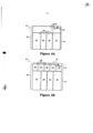
[0030] A FIG. 5 é uma vista superior expandida de uma parte distal de uma tira de testes inserida num conector de tiras de medidor, de acordo com uma modalidade da presente invenção.[0030] FIG. 5 is an exploded top view of a distal portion of a test strip inserted into a meter strip connector, in accordance with an embodiment of the present invention.
[0031] A FIG. 6 é uma vista superior de uma parte distal de uma tira de testes que ilustra uma pluralidade de contatos elétricos que formam um código, de acordo com uma modalidade da presente invenção.[0031] FIG. 6 is a top view of a distal portion of a test strip illustrating a plurality of electrical contacts forming a code, in accordance with an embodiment of the present invention.
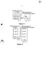
[0032] A FIG. 7 é um diagrama esquemático simplificado das conexões elétricas entre um medidor e uma pluralidade de contatos elétricos de uma tira de testes, de acordo com uma modalidade da presente invenção.[0032] FIG. 7 is a simplified schematic diagram of electrical connections between a meter and a plurality of electrical contacts of a test strip, in accordance with an embodiment of the present invention.
[0033] A FIG. 8 é um diagrama esquemático alternativo simplificado das conexões elétricas entre um medidor e uma pluralidade de contatos elétricos de uma tira de testes, de acordo com uma modalidade da invenção.[0033] FIG. 8 is an alternative simplified schematic diagram of electrical connections between a meter and a plurality of electrical contacts of a test strip, in accordance with an embodiment of the invention.
[0034] Agora, será feita referência em detalhe a modalidades exemplificativas da invenção, cujos exemplos são ilustrados nos desenhos anexos. Sempre que possível, serão usados os mesmos números de referência através dos desenhos para referência às mesmas ou partes semelhantes.[0034] Now, reference will be made in detail to exemplary embodiments of the invention, examples of which are illustrated in the accompanying drawings. Wherever possible, the same reference numbers will be used throughout the drawings to refer to the same or similar parts.
[0035] De acordo com modalidades exemplificativas, a invenção relaciona-se com um sistema para medir um constituinte de corpo fluido inclui uma tira de testes e um medidor. Uma tira de testes individual pode também incluir um código embutido relativo a dados associados a um lote de tiras de teste ou dados particulares para aquela tira individual. As informações embutidas apresentam dados legíveis pelo medidor sinalizando ao microprocessador do medidor que acesse e utilize um conjunto específico de parâmetros particulares de calibração armazenados para testar tiras de um lote de fabrico a que a tira individual pertence ou para uma tira de testes individual. O sistema pode também incluir uma tira de verificação que o usuário pode inserir no medidor para verificar que o instrumento está eletricamente calibrado e corretamente em funcionamento. Para os propósitos desta revelação, “distal” refere-se à parte de uma tira de testes afastada do operador do dispositivo durante o uso normal e “proximal” refere-se à parte mais próxima do operador do dispositivo durante o uso normal.[0035] According to exemplary embodiments, the invention relates to a system for measuring a fluid body constituent including a test strip and a meter. An individual test strip may also include embedded code relating to data associated with a lot of test strips or data particular to that individual strip. Embedded information presents meter-readable data signaling the meter's microprocessor to access and use a specific set of particular stored calibration parameters to test strips from a manufacturing lot to which the individual strip belongs or for an individual test strip. The system may also include a check strip that the user can insert into the meter to verify that the instrument is electrically calibrated and functioning correctly. For purposes of this disclosure, "distal" refers to the portion of a test strip away from the operator of the device during normal use and "proximal" refers to the portion closest to the operator of the device during normal use.
[0036] A tira de testes pode incluir uma câmara de amostras para receber uma amostra de fluido do usuário, tal como, por exemplo, uma amostra de sangue. A câmara de amostras e a tira de testes do presente Relatório Descritivo podem ser formadas usando materiais e métodos descritos na Patente US 6.743.635 comumente possuída, que fica por este meio incorporada por referência na sua totalidade. Conseqüentemente, a câmara de amostras pode incluir uma primeira abertura na extremidade proximal da tira de testes e uma segunda abertura para desabafar a câmara de amostras. A câmara de amostras pode ser dimensionada para poder retirar a amostra de sangue através da primeira abertura e segurar a amostra de sangue na câmara de amostras, por ação capilar. A tira de testes pode incluir uma seção afunilada que é mais estreita na extremidade proximal ou pode incluir outros indícios, a fim de tornar mais fácil para o usuário localizar a primeira abertura e aplicar a amostra de sangue.[0036] The test strip may include a sample chamber for receiving a fluid sample from the user, such as, for example, a blood sample. The sample chamber and test strip of the present Specification may be formed using materials and methods described in commonly owned US Patent 6,743,635, which is hereby incorporated by reference in its entirety. Accordingly, the sample chamber may include a first opening at the proximal end of the test strip and a second opening for venting the sample chamber. The sample chamber can be sized to be able to draw the blood sample through the first opening and hold the blood sample in the sample chamber by capillary action. The test strip may include a tapered section that is narrower at the proximal end or may include other indicia to make it easier for the user to locate the first opening and apply the blood sample.
[0037] Um eletrodo de trabalho e um eletrodo contador podem ser dispostos na câmara de amostras opcionalmente com eletrodos de detecção de enchido. Uma camada de reativo é disposta na câmara de amostras e contata, de preferência, pelo menos o eletrodo de trabalho. A camada de reativo pode incluir uma enzima, tal como oxidase da glicose, e um mediador, tal como ferricianeto de potássio ou hexamina de rutênio. A tira de testes tem, próximo de sua extremidade distal, uma primeira pluralidade de contatos elétricos da tira que são eletricamente conectados aos eletrodos via traços condutores. Além disso, a tira de testes pode também incluir uma segunda pluralidade de contatos elétricos da tira próximo da extremidade distal da tira. A segunda pluralidade de contatos elétricos pode ser disposta de tal modo que proporcionam, quando a tira é inserida no medidor, um código de lote distintamente discernível legível pelo medidor. Como notado acima, o código legível pode ser lido como um sinal para acessar dados, tais como coeficientes de calibração, a partir de uma unidade de memória interna (on-board) no medidor relacionada com tiras de teste a partir desse lote ou mesmo informações que correspondem a tiras de teste individuais.[0037] A working electrode and a counter electrode can be arranged in the sample chamber optionally with filling detection electrodes. A layer of reagent is placed in the sample chamber and preferably contacts at least the working electrode. The reagent layer can include an enzyme, such as glucose oxidase, and a mediator, such as potassium ferricyanide or ruthenium hexamine. The test strip has, near its distal end, a first plurality of electrical strip contacts which are electrically connected to the electrodes via conductive traces. In addition, the test strip may also include a second plurality of electrical strip contacts near the distal end of the strip. The second plurality of electrical contacts may be arranged such that they provide, when the strip is inserted into the meter, a distinctly discernible batch code readable by the meter. As noted above, the readable code can be read as a signal to access data, such as calibration coefficients, from an on-board memory unit in the meter relating to test strips from that lot or even information. that correspond to individual test strips.
[0038] O medidor pode ser alimentado por bateria e pode permanecer num modo dormente de baixa energia, quando não em uso, a fim de economizar energia. Quando a tira de testes é inserida no medidor, a primeira e a segunda pluralidade de contatos elétricos na tira de testes contata os contatos elétricos correspondentes no medidor. A segunda pluralidade de contatos elétricos pode formar ponte com um par de contatos elétricos no medidor, ocasionando que uma corrente flua através de uma parte da segunda pluralidade de contatos elétricos. O fluxo de corrente através da segunda pluralidade de contatos elétricos ocasiona que o medidor acorde e entre num modo ativo. O medidor também lê as informações de código fornecidas pela segunda pluralidade e pode, então, identificar, por exemplo, o teste particular a ser realizado ou uma confirmação do status operacional adequado. Além disso, o medidor também pode identificar a tira inserida como uma tira de testes ou uma tira de verificação com base nas informações de código particulares. Se o medidor detectar uma tira de verificação, realiza uma seqüência de tira de verificação. Se o medidor detectar uma tira de testes, realiza uma seqüência de tira de testes.[0038] The meter can be battery powered and can remain in a low power sleep mode when not in use in order to save energy. When the test strip is inserted into the meter, the first and second plurality of electrical contacts on the test strip contact corresponding electrical contacts on the meter. The second plurality of electrical contacts can bridge a pair of electrical contacts on the meter, causing a current to flow through a portion of the second plurality of electrical contacts. Current flow through the second plurality of electrical contacts causes the meter to wake up and enter an active mode. The meter also reads the code information provided by the second plurality and can then identify, for example, the particular test to be performed or a confirmation of proper operating status. In addition, the meter can also identify the inserted strip as a test strip or a check strip based on the particular code information. If the meter detects a check strip, it performs a check strip sequence. If the meter detects a test strip, it performs a test strip sequence.
[0039] Na sequência de tira de testes, o medidor valida o eletrodo operacional, o eletrodo contador e, se incluído, os eletrodos de detecção de enchimento, confirmando que não existe nenhum trajeto de baixa impedância entre quaisquer destes eletrodos. Se os eletrodos são válidos, o medidor indica para o usuário que a amostra pode ser aplicada na tira de testes. O medidor aplica, então, uma voltagem de detecção de queda entre os eletrodos de funcionamento e contador e detecta uma amostra de fluido, por exemplo, uma amostra de sangue, detectando um fluxo de corrente entre os eletrodos de funcionamento e contador (isto é, um fluxo de corrente através da amostra de sangue à medida que ela forma ponte com os eletrodos de funcionamento e contador). Para detectar que uma amostra adequada está presente na câmara de amostras e que a amostra de sangue atravessou a camada de reativo e se misturou com os constituintes químicos na camada de reativo, o medidor pode aplicar uma voltagem de detecção de queda entre os eletrodos de detecção de enchimento e medir qualquer corrente resultante fluindo entre os eletrodos de detecção de enchimento. Se esta corrente resultante alcançar um nível suficiente dentro de um período predeterminado de tempo, o medidor indica ao usuário que uma amostra adequada está presente e se misturou com a camada de reativo.[0039] In the test strip sequence, the meter validates the operating electrode, the counter electrode and, if included, the filling detection electrodes, confirming that there is no low impedance path between any of these electrodes. If the electrodes are valid, the meter indicates to the user that the sample can be applied to the test strip. The meter then applies a dip detection voltage between the working and counter electrodes and senses a fluid sample, for example a blood sample, by detecting a current flow between the working and counter electrodes (i.e., a current flow through the blood sample as it bridges the working and counter electrodes). To detect that an adequate sample is present in the sample chamber and that the blood sample has passed through the reagent layer and mixed with the chemical constituents in the reagent layer, the meter can apply a drop detection voltage between the detection electrodes and measure any resulting current flowing between the filling sensing electrodes. If this resulting current reaches a sufficient level within a predetermined period of time, the meter indicates to the user that an adequate sample is present and has mixed with the reagent layer.
[0040] O medidor pode ser programado para esperar um período predeterminado de tempo depois de detectar inicialmente a amostra de sangue, para permitir que a amostra de sangue reaja com a camada de reativo ou pode começar imediatamente a tomar leituras em seqüência. Durante um período de medição de fluidos, o medidor aplica uma voltagem de ensaio entre os eletrodos de funcionamento e contador e toma uma ou mais medições da corrente resultante que flui entre os eletrodos de funcionamento e contador. A voltagem de ensaio é próxima do potencial redox da química na camada de reativo e a corrente resultante é relacionada com a concentração do constituinte particular mensurado, tal como, por exemplo, o nível de glicose numa amostra de sangue.[0040] The meter can be programmed to wait a predetermined period of time after initially detecting the blood sample, to allow the blood sample to react with the reagent layer, or it can immediately begin taking sequential readings. During a fluid measurement period, the meter applies a test voltage between the working and counter electrodes and takes one or more measurements of the resultant current flowing between the working and counter electrodes. The test voltage is close to the redox potential of the chemistry in the reagent layer and the resulting current is related to the concentration of the particular constituent being measured, such as, for example, the level of glucose in a blood sample.
[0041] Num exemplo, a camada de reativo pode reagir com a glicose na amostra de sangue, a fim de determinar a concentração de glicose particular. Num exemplo, a oxidase da glicose é usada na camada de reativo. Pretende-se que o detalhamento da oxidase da glicose seja apenas um exemplo e podem ser usados outros materiais sem sair do escopo da invenção. Outros mediadores possíveis incluem, mas sem limitação, rutênio, ósmio e unobtainium. Durante um teste de amostra, a oxidase da glicose inicia uma reação que oxida a glicose a ácido glucônico e reduz o ferricianeto a ferrocianeto. Quando é aplicada uma voltagem apropriada a um eletrodo de trabalho, em relação a um eletrodo contador, o ferrocianeto é oxidado a ferricianeto, gerando, assim, uma corrente que se relaciona com a concentração de glicose na amostra de sangue. O medidor, então, calcula o nível de glicose com base na corrente mensurada e em dados de calibração que o medidor foi sinalizado acessar pelos dados de código lidos a partir da segunda pluralidade de contatos elétricos associados com a tira de testes. O medidor, então, exibe o nível de glicose calculado para o usuário. Cada um dos componentes acima descritos e a sua interconexão serão, agora, descritos.[0041] In one example, the reagent layer can react with glucose in the blood sample in order to determine the particular glucose concentration. In one example, glucose oxidase is used in the reagent layer. The breakdown of glucose oxidase is intended to be an example only and other materials may be used without departing from the scope of the invention. Other possible mediators include, but are not limited to, ruthenium, osmium, and unobtainium. During a sample test, glucose oxidase initiates a reaction that oxidizes glucose to gluconic acid and reduces ferricyanide to ferrocyanide. When an appropriate voltage is applied to a working electrode relative to a counter electrode, ferrocyanide is oxidized to ferricyanide, thereby generating a current that relates to the glucose concentration in the blood sample. The meter then calculates the glucose level based on the measured current and calibration data that the meter has been signaled to access by code data read from the second plurality of electrical contacts associated with the test strip. The meter then displays the calculated glucose level to the user. Each of the components described above and their interconnection will now be described.
[0042] A Figura 1 ilustra uma vista geral em seção reta de uma modalidade de uma tira de testes 10. A tira de testes 10 inclui uma extremidade de conexão proximal 12, uma extremidade distal 14 e é formada com uma camada de base 16 que se estende ao longo do comprimento inteiro da tira de testes 10. A camada de base 16 é composta, de preferência, de um material eletricamente isolante e tem uma espessura suficiente para proporcionar suporte estrutural para a tira de teste 10. Para propósitos desta aplicação, um material isolante (por exemplo, uma camada isolante, um revestimento, uma tinta ou substrato etc.) compreende qualquer material em que os elétrons ou íons não possam ser deslocados facilmente, impedindo, assim, o fluxo de corrente elétrica. Conseqüentemente, um elemento pode ser dito estar isolado, quando for separado a partir de outras superfícies condutoras por uma substância dielétrica ou espaço de ar oferecendo permanentemente uma elevada resistência para a passagem de corrente e para a descarga de ruptura através da substância ou espaço. Em contraste, para propósitos desta aplicação, um elemento resistivo é um que introduz um nível aumentado de impedância num circuito que reduz (mas, não necessariamente impede) o fluxo de corrente elétrica. A camada de base 16, por exemplo, pode ser um poliéster que seja de mais ou menos 0,35 milímetros de espessura, embora possam ser usados outros tamanhos, dependendo da aplicação particular e do método de fabrico. Disposto sobre a camada de base 16 está um padrão condutor (não mostrado).[0042] Figure 1 illustrates an overview in cross section of one embodiment of a test strip 10. The test strip 10 includes a proximal connecting end 12, a distal end 14 and is formed with a base layer 16 that extends along the entire length of the test strip 10. The base layer 16 is preferably composed of an electrically insulating material and is of sufficient thickness to provide structural support for the test strip 10. For purposes of this application, an insulating material (eg, an insulating layer, a coating, a paint or substrate, etc.) comprises any material in which electrons or ions cannot easily be displaced, thereby impeding the flow of electric current. Consequently, an element may be said to be isolated when it is separated from other conductive surfaces by a dielectric substance or air gap permanently offering a high resistance to the passage of current and to the breakdown discharge through the substance or gap. In contrast, for purposes of this application, a resistive element is one that introduces an increased level of impedance into a circuit that reduces (but not necessarily prevents) the flow of electrical current. The base layer 16, for example, can be a polyester that is plus or minus 0.35 millimeters thick, although other sizes can be used depending on the particular application and method of manufacture. Arranged over the base layer 16 is a conductive pattern (not shown).
[0043] O padrão condutor inclui uma pluralidade de eletrodos dispostos sobre a camada de base 16 próximo da extremidade proximal 12, uma pluralidade de contatos elétricos da tira dispostos sobre a camada de base 16 próximo da extremidade distal 14 e uma pluralidade de traços condutores que conectam eletricamente os eletrodos à pluralidade de contatos elétricos da tira. Para propósitos desta aplicação, o substantivo “contato” denota uma área pretendida para ligação mecânica com outro “contato” correspondente independentemente de um circuito elétrico ser completado ou passar através da área particular.[0043] The conductive pattern includes a plurality of electrodes disposed on the base layer 16 near the proximal end 12, a plurality of strip electrical contacts disposed on the base layer 16 near the distal end 14, and a plurality of conductive traces that electrically connect the electrodes to the strip's plurality of electrical contacts. For purposes of this application, the noun "contact" denotes an area intended for mechanical connection with another corresponding "contact" regardless of whether an electrical circuit is completed or passes through the particular area.
[0044] Numa modalidade, a pluralidade de eletrodos pode incluir um eletrodo de trabalho, um eletrodo contador e eletrodos de detecção de enchimento. O padrão condutor pode ser aplicado aplicando um material condutor sobre a camada de base 16. O padrão condutor pode ser aplicado ao lado superior da tira, ao lado inferior da tira ou uma combinação de ambos. O material de eletrodo pode ser fornecido por crepitação no vazio de filme fino de um material condutor (por exemplo, ouro) e um material semicondutor (por exemplo, óxido de zinco de índio) sobre a camada de base 16. A camada de eletrodo resultante pode, então, mais padronizada de acordo com a aplicação específica formando regiões/trajetos condutores particulares através um processo de separação de laser. Podem ser empregados materiais e métodos alternativos para prover um padrão condutor além de impressão de tela sem sair do escopo da invenção.[0044] In one embodiment, the plurality of electrodes may include a working electrode, a counter electrode, and fill-sensing electrodes. The conductive pattern can be applied by applying a conductive material over the base layer 16. The conductive pattern can be applied to the top side of the strip, to the bottom side of the strip, or a combination of both. The electrode material can be provided by sputtering in the vacuum thin film of a conductive material (eg gold) and a semiconductor material (eg indium zinc oxide) onto the base layer 16. The resulting electrode layer it can then be further patterned according to the specific application forming particular conductive regions/pathways through a laser separation process. Alternative materials and methods can be employed to provide a conductive pattern beyond screen printing without departing from the scope of the invention.
[0045] Uma camada isolante dielétrica 18 pode ser formada acima do padrão condutor ao longo de uma parte da tira de testes entre os eletrodos de medição e a pluralidade de contatos elétricos da tira, a fim de impedir arranhões e outros danos para a conexão elétrica. Como visto na Figura 1, a extremidade proximal 12 da tira de testes 10 inclui uma localização de recebimento de amostra, tal como uma câmara de amostras 20 configurada para receber a amostra de fluido do paciente, conforme descrito acima. A câmara de amostras 20 pode ser formada em parte através uma fenda formada entre uma cobertura 22 e os eletrodos de medição subjacentes formados na camada de base 16. A posição relativa dos eletrodos de medição e os contatos elétricos da tira formam uma região de eletrodo proximal 24 numa extremidade da tira 10 e uma região de contato distal da tira 26 na outra extremidade.[0045] A dielectric insulating
[0046] Com referência à Figura 2, é ilustrada uma vista em perspectiva superior de uma tira de testes 10 inserida num conector do medidor 30. Como visto na Figura 2, a tira 10 inclui uma região proximal de eletrodo 24, que contém a câmara de amostras e eletrodos de medição acima descritos. A região proximal de eletrodo 24 pode ser formada de modo a ter um formato particular, a fim de distinguir, para o usuário, a extremidade que recebe uma amostra de fluido a partir da região de contato distal da tira 26. O conector do medidor 30 inclui o canal 32 que se estende para fora para uma abertura chamejada para recebimento da tira de testes 10. O conector 30 pode inclui ainda sabores 36 que se estendem a uma altura predeterminada acima da base de canal 32. A altura predeterminada de sabores 36 é selecionada de forma a limitar a extensão, tal como através de uma camada levantada correspondente da tira de testes 10, em que pode ser inserida uma tira de testes 10 no canal 32.[0046] With reference to Figure 2, a top perspective view of a test strip 10 inserted into a
[0047] O conector 30 inclui ainda uma primeira pluralidade de contatos de conector 38, dispostos mais próximos da extremidade proximal do conector 30, e uma segunda pluralidade de contatos de conector 40, dispostos mais próximos da extremidade distal do conector 30. Conforme ilustrado, a tira de testes 10 é inserida na abertura chamejada com a região de contatos da tira distal 26 se estendendo primeiro através do canal do conector 32. Com referência à Figura 3, é ilustrada uma vista geral da seção reta de uma tira de testes inserida num conector de tiras do medidor 30. O canal 32 representa uma fila proximal de conectores que compreende uma primeira pluralidade de contatos de conector 38. Além disso, o canal 32 aloja uma fila distal de conectores compreendendo uma segunda pluralidade de contatos de conector 40. Os contatos de conector 38 e 40 fazem contato com partes distintas da região de contatos da tira distal 26, como será descrito mais completamente abaixo.[0047] The
[0048] A Figura 4A é uma vista superior de uma parte distal de uma tira de testes 10 que ilustra a região de contatos da tira distal 26. O padrão condutor formado sobre a camada de base 16 estende-se ao longo da tira 10 de forma a incluir a região de contatos da tira distal 26. Como ilustrado na Figura 4A, a região de contatos da tira distal 26 é dividida de maneira a formar duas regiões condutoras distintas, 42 e 44, respectivamente. A região condutora 44 é dividida em quatro colunas que formam uma primeira pluralidade de contatos elétricos da tira, etiquetados 46, 48, 50, e 52 respectivamente. A primeira pluralidade de contatos elétricos da tira está eletricamente conectada à pluralidade de eletrodos de medição na extremidade distal da tira de testes 10, conforme explicado acima. Deve ser entendido que os quatro contatos 46-52 são meramente exemplificativos e o sistema poderia incluir menos ou mais contatos elétricos de tira correspondentes ao número de eletrodos de medição incluídos no sistema.[0048] Figure 4A is a top view of a distal portion of a test strip 10 illustrating the contact region of the
[0049] A primeira pluralidade de contatos elétricos da tira 46-52 é dividida, por exemplo, através de interruptores 54 formados através do padrão condutor subjacente na tira de testes 10. Estes interruptores poderiam ser formados no padrão condutor durante a impressão, através um processo de traçagem de linhas, remoção a laser ou através de um processo do tipo químico/fotogravação. Além disso, outros processos de formação de interrupções de condutor por remoção de um condutor na tira de testes 10 podem ser usados, como seria evidente para uma pessoa de capacidade ordinária na técnica. Um interruptor adicional 54 divide a região condutora 44 da região condutora 42 dentro da região de contatos da tira distal 26 e um interruptor adicional 54 separa a parte superior à direita da região de contatos da tira distal 26 para formar uma região de entalhes 56, como será descrito mais completamente em detalhes abaixo.[0049] The first plurality of electrical contacts of the strip 46-52 are divided, for example, through switches 54 formed through the underlying conductive pattern in the test strip 10. These switches could be formed in the conductive pattern during printing, through a line drawing process, laser removal or through a chemical/photoetching type process. In addition, other methods of forming conductor breaks by removing a conductor on test strip 10 can be used, as would be apparent to a person of ordinary skill in the art. An additional switch 54 divides the
[0050] A Figura 4B ilustra uma vista adicional da região de contatos da tira distal 26. Na Figura 4B, a região condutora 42, descrita acima no que se relaciona com a Figura 4A, é dividida em cinco regiões distintas que delineiam uma segunda pluralidade de contatos elétricos da tira que formam os blocos de contatos 58, 60, 62, 64 e 66, respectivamente. A segunda pluralidade de contatos elétricos da tira que forma os blocos de contatos 58, 60, 62, 64 e 66 pode ser dividida através do mesmo processo usado para dividir a primeira pluralidade de contatos elétricos da tira, 46, 48, 50 e 52, acima descritos. Como notado acima, o padrão condutor sobre a camada de base 16, que, pelo menos em parte, forma os contatos elétricos da tira, pode ser aplicado ao lado superior da tira, ao lado inferior da tira ou a uma combinação de ambos. Os blocos de contatos 58, 60, 62, 64 e 66 são configurados de forma a serem operativamente conectados à segunda pluralidade de contatos de conector 40 dentro do conector do medidor 30. Através esta conexão operativa, o medidor é apresentado e lê a partir dos blocos de contatos um código particular que representa informações que sinalizam ao medidor que acesse dados relacionados com a tira de testes subjacente 10. Além disso, a Figura 4B representa um padrão adicional de interruptores 68, isolando uma extremidade externa de conexão distal 70 da região de contatos da tira distal 26.[0050] Figure 4B illustrates an additional view of the region of contacts of the
[0051] A Figura 4C ilustra uma vista adicional da região de contatos da tira distal 26. Na Figura 4C, a região de contatos da tira distal 26 é representada como incluindo a primeira pluralidade de contatos elétricos da tira 46-52, formando a segunda pluralidade de contatos elétricos da tira blocos de contatos 58, 60, 62, 64 e 66 e a região separada de entalhes 56. Conforme notado, as regiões condutoras acima descritas podem ser todas formadas como resultado de interruptores 54 dentro do padrão condutor subjacente da tira de testes 10.[0051] Figure 4C illustrates a further view of the contact region of the
[0052] A Figura 4D ilustra características adicionais da região de contatos da tira distal 26. Uma tira de tinta isolante não condutora 72 pode proporcionar separação adicional entre a região condutora 44 e a região condutora 42 dentro da região de contatos da tira distal 26. As bordas entre as duas regiões podem ser impressas com a tinta isolante 72, a fim de manter áreas distintas de condutividade (limitadas por uma área distinta de isolamento) e impedir arranhões pelos contatos do conector do medidor durante o processo de inserção da tira, que pode afetar adversamente a condutividade pretendida de um dos contatos da tira. A tinta isolante não condutora 72 pode ser administrada, por exemplo, através um processo de impressão de tela. Essa impressão de tela de um revestimento de isolamento dielétrico é vantajosa na medida em que pode ser aplicado mais tarde no processo de fabrico de tira e num padrão facilmente programável/reprodutível. A etapa adicional de somar esse revestimento isolante pode ser menos cara e demorada do que métodos que exigem a ablação do substrato de alguma forma. Por exemplo, remover uma superfície de substrato através um processo de ablação a laser ou químico envolve um processo demorado de remover com precisão um padrão particular de material preexistente.[0052] Figure 4D illustrates additional features of the contact region of the
[0053] A Figura 4D ilustra que tira de testes 10 pode incluir outra tira de tinta isolante não-condutora 73 formada na extremidade distal da tira de testes 10. A tira de tinta isolante não condutora 73 proporciona uma região não condutora na extremidade distal da tira 10. A tira 73 impede, assim, que quaisquer contatos do conector do medidor criem uma conexão condutora ativa com qualquer parte dos blocos de contatos 58, 60, 62, 64 e 66 antes que a tira esteja completamente inserida no medidor. Conseqüentemente, a tira 73 provê uma característica adicional para assegurar uma conexão adequada entre a tira de testes 10 e o medidor correspondente.[0053] Figure 4D illustrates that test strip 10 may include another non-conductive insulating ink strip 73 formed at the distal end of the test strip 10. The non-conductive insulating ink strip 73 provides a non-conductive region at the distal end of the test strip. strip 10. Strip 73 thus prevents any meter connector contacts from creating an active conductive connection with any part of contact blocks 58, 60, 62, 64 and 66 before the strip is fully inserted into the meter. Accordingly, the strip 73 provides an additional feature to ensure a proper connection between the test strip 10 and the corresponding meter.
[0054] Com referência à Figura 5, o conector de tiras do medidor 30 é ilustrado recebendo uma região de contatos da tira distal 26 da tira de testes 10. A Figura 5 representa uma primeira pluralidade de contatos de conector 38, etiquetados 1-4 respectivamente, e uma segunda pluralidade de contatos de conector 40, etiquetados 5-9. Os contatos de conector 38 e 40 fazem contato com partes distintas da região de contatos da tira distal 26. Em particular, após a inserção adequada da tira de testes 10 no conector 30, os contatos elétricos da tira 46-52, que formam a primeira pluralidade de contatos elétricos da tira, são respectivamente conectados eletricamente aos contatos de conector 1-4, que formam a primeira pluralidade de contatos de conector 38. De modo semelhante, os blocos de contatos 58, 60, 62, 64 e 66, que formam a segunda pluralidade de contatos elétricos da tira, são conectados eletricamente respectivamente aos contatos de conector 5-9, que formam a segunda pluralidade de contatos de conector 40.[0054] Referring to Figure 5, the
[0055] Como visto na Figura 5, a primeira pluralidade de contatos de conector 38 está disposta lateralmente em ziguezague ou deslocada, em relação à segunda pluralidade de contatos do conector 40. Embora a primeira e a segunda pluralidades sejam ilustradas como estando em filas e desviadas umas das outras, elas não precisam estar em filas distintas e podem, ao invés, ser desviadas de uma maneira adicional, tal como, por exemplo, em grupos distintos. Conseqüentemente, à medida que uma tira de testes 10 é inserida no conector do medidor 30, o sinal condutor provido pelos blocos de contatos 58-66 é desimpedido por quaisquer arranhões ou desgastes que de outra forma resultariam de primeiramente deslizar os blocos de contatos 58-66 sob os contatos de conector 1-4, a fim de alcançar a sua conexão de destino nos contatos de conector 5-9. Portanto, a disposição em ziguezague dos contatos de conector 38 em relação aos contatos do conector 40 proporciona uma conexão mais confiável. Além disso, a aplicação da tira 72 de tinta isolante não condutora (Figura 4D) também ajude a impedir que o revestimento condutor de um dos blocos de contatos 58- 66 seja arranhado e “enrugado” para fora pela fricção e interação a partir dos contatos do conector do medidor 38. Conseqüentemente, a tira 72 de tinta isolante não condutora proporciona confiabilidade aumentada de condução do conector e dos contatos.[0055] As seen in Figure 5, the first plurality of connector contacts 38 are disposed laterally in a zigzag or offset, relative to the second plurality of
[0056] Numa modalidade, a conexão entre o bloco de contatos 66 e os contatos de conector 9 estabelece uma conexão comum com a terra (ou uma fonte de voltagem em que a polaridade é invertida), completando, assim, um circuito elétrico, que inclui o medidor e pelo menos uma parte de região condutora 42. A conclusão deste circuito pode realizar uma função de acordar o medidor, fornecendo um sinal para o medidor para ativar-se a partir do modo de dormir de baixa energia. Portanto, como ilustrado na Figura 5, o contato do conector 9 pode ser posicionado proximamente em relação aos contatos restantes 5-8, a fim de assegurar que os conectores 5-8 estão em posição de conexão adequada antes do fechamento/despertar final do circuito através da conexão do bloco de contatos 66 e os contatos do conector 9. Além disso, como pode ser formada uma tira de tinta isolante não condutora 73 (ver a Figura 4D) na extremidade distal da tira de testes 10 e também porque uma substância condutora pode ser removida da região de entalhes 56 (ver a Figura 4C), será impedido o despertar prematuro do medidor.[0056] In one embodiment, the connection between the
[0057] Em outras palavras, durante o movimento distal da tira de testes 10 dentro do canal conector 32, a conexão comum não será estabelecida no ponto em que o contato do conector 9 se liga à extremidade distal extrema da tira de testes 10. Ao invés, a conexão comum será estabelecida apenas quando o contato do conector passar o entalhe 56 e for aplicada a tira de tinta 73 e envolve uma parte condutora do bloco de contatos 66. Conseqüentemente, a combinação de um contato de conector 9 posicionado de modo proximal e uma região de entalhe não condutora 56 proporciona uma conexão mais confiável entre a tira 10 e o medidor.[0057] In other words, during the distal movement of the test strip 10 within the connector channel 32, the common connection will not be established at the point where the contact of the connector 9 connects to the extreme distal end of the test strip 10. instead, the common connection will be established only when the connector contact passes the
[0058] Como notado acima, os blocos de contatos 58, 60, 62, 64 e 66 são configurados para serem operativamente conectados à segunda pluralidade de contatos do conector 40 dentro do conector do medidor 30. Através desta conexão operativa, o medidor é apresentado e lê a partir dos blocos de contatos um código particular que sinaliza ao medidor que acesse informações relacionadas a uma tira de testes subjacente particular 10. As informações codificadas podem sinalizar ao medidor que acesse dados, incluindo, mas, sem limitação, parâmetros que indicam o teste particular a ser realizado, parâmetros que indicam a conexão a uma sonda de teste, parâmetros que indicam a conexão para uma tira de verificação, coeficientes de calibração, coeficientes de correção de temperatura, coeficientes de correção do nível de pH, dados de correção de hematócrito e dados para reconhecer uma marca de tira de testes particular.[0058] As noted above, contact blocks 58, 60, 62, 64 and 66 are configured to be operatively connected to the second plurality of contacts of
[0059] Um desses códigos está ilustrado na Figura 6, em que blocos de contatos condutores 60 e 64 estão sobreimpressos num material isolante elétrico, tal como, por exemplo, uma camada de tinta (isolante) não condutora 75. Uma camada de tinta não condutora 75 aumenta significativamente a impedância (e pode mesmo impedir o fluxo de corrente elétrica) entre os contatos do conector correspondente (neste exemplo, os contatos de conector 6 e 8) e a parte de tira subjacente em vários blocos de contatos predeterminados dentro da região condutora 42 da região de contatos da tira distal 26. Da mesma maneira acima descrita, no que se relaciona com a Figura 4D, o uso de tinta isolante não condutora 75 é particularmente vantajoso em relação a outros métodos de alteração da condutividade de uma parte de tira.[0059] One of these codes is illustrated in Figure 6, in which conductive contact blocks 60 and 64 are overprinted on an electrically insulating material, such as, for example, a layer of non-conductive (insulating) paint 75. A layer of non-conductive paint conductor 75 significantly increases the impedance (and may even impede the flow of electric current) between the mating connector contacts (in this example, connector contacts 6 and 8) and the underlying strip portion at several predetermined contact blocks within the region conductive 42 of the contact region of the
[0060] Um material isolante exemplificativo inclui, mas sem limitação, VISTASPEC HB Black disponível a partir de Aellora™ Digital de Keene, New Hampshire. O material VISTASPEC HB Black é uma tinta híbrida pigmentada de preto curável por UV para uso em conjuntos piezo de jato de tinta de gotejamento sob demanda a temperatura elevada. Esta tinta VISTASPEC é jateada a uma temperatura elevada, seca rapidamente após contato com o substrato subjacente e é, então, curada por radiação UV. As propriedades da tinta incluem isolamento elétrico, resistência à abrasão de contatos do medidor, adesão intensificada a um material condutor subjacente e características viscoelásticas benéficas. Às características viscoelásticas do material minimizam o espalhamento da tinta sobre o substrato subjacente. Além disso, estas características viscoelásticas possibilitam que esta tinta seja utilizada com tecnologia piezo com elevada resolução de impressão que possibilita a padronagem precisa e exata da tinta VISTASPEC sobre o substrato de eletrodo condutor. Além disso, as características viscoelásticas da tinta VISTASPEC possibilitam que uma amostra tão pequena quanto 80 picolitros caia de modo a permanecer espetada na posição em que faz contato com o substrato subjacente, possibilitando, assim, tamanhos de bloco precisos, exatidão posicional e precisão de até menos do que cerca de 0,13 milímetros. Como exemplo, a impressão do material isolante pode ser realizada através do uso de um motor de impressão a jato de tinta de gotejamento sob demanda piezo de passo único SureFire Model PE- 600-10, também disponível a partir de Aellora™ Digital de Keene, New Hampshire. Como exemplos não limitativos, o motor de impressão a jato de tinta acima descrito pode utilizar cabeçotes de impressão do modelo Nova e Galaxy, disponíveis a partir de Spectra Inc., de Líbano, New Hampshire.[0060] An exemplary insulating material includes, but is not limited to, VIEWTASPEC HB Black available from Aellora™ Digital of Keene, New Hampshire. The VISTASPEC HB Black material is a UV-curable black pigmented hybrid ink for use in high temperature piezo drip-on-demand inkjet assemblies. This VISTASPEC ink is blasted at an elevated temperature, dries quickly upon contact with the underlying substrate and is then cured by UV radiation. Ink properties include electrical insulation, resistance to abrasion of gauge contacts, enhanced adhesion to an underlying conductive material, and beneficial viscoelastic characteristics. The viscoelastic characteristics of the material minimize ink spreading over the underlying substrate. In addition, these viscoelastic characteristics make it possible for this ink to be used with piezo technology with high printing resolution that enables the precise and exact patterning of the VISTASPEC ink on the conductive electrode substrate. In addition, the viscoelastic characteristics of VISTASPEC ink allow a sample as small as 80 picoliters to drop to remain pinned in the position where it makes contact with the underlying substrate, thus enabling precise block sizes, positional accuracy and accuracy of up to less than about 0.13mm. As an example, printing of the insulating material can be accomplished through the use of a SureFire Model PE-600-10 single-pass piezo drip-on-demand inkjet print engine, also available from Keene's Aellora™ Digital, New Hampshire. As non-limiting examples, the inkjet print engine described above may utilize Nova and Galaxy model printheads available from Spectra Inc. of Lebanon, New Hampshire.
[0061] Os sistemas que exigem a ablação de uma superfície de substrato através um processo de separação químico ou a laser envolvem o processo demorado de remover com precisão um padrão particular de material preexistente. Como a codificação da tira ocorre mais tarde no processo de montagem do que a etapa de separação, adicionar uma camada de tinta não condutora 75 aos blocos de contatos elimina os temas de tolerância que resultariam de reintroduzir tiras num processo de ablação maior para codificação. Essa impressão de uma camada de isolamento dielétrico é vantajosa na medida em que pode ser aplicada mais tarde no processo de fabrico de tira e num padrão facilmente programável/reprodutível. Como exemplo não limitativo, o método de prover a camada 75 no substrato subjacente pode incluir o uso de pelo menos um dado de registro ao longo da tira subjacente para assegurar a formação precisa da camada 75, de acordo com um padrão particular pretendido. Por exemplo, os dados podem ser fornecidos ortogonalmente (por exemplo, longitudinal e lateralmente) ao longo de um substrato onde isso pode ser mecânica ou oticamente referenciado por um aparelho de impressão para facilitar a formação de um padrão preciso e reproduzível. Dependendo da disposição dos contatos elétricos da tira, as partes discretas do material isolante elétrico que formam cada camada 75 podem ser aplicadas ao lado superior da tira, ao lado inferior da tira ou uma combinação de ambos.[0061] Systems that require the ablation of a substrate surface through a chemical or laser separation process involve the time-consuming process of precisely removing a particular pattern of pre-existing material. Since strip coding occurs later in the assembly process than the separation step, adding a layer of non-conductive ink 75 to the contact pads eliminates tolerance issues that would result from reintroducing strips into a larger ablation process for coding. Such printing of a dielectric insulating layer is advantageous in that it can be applied later in the strip manufacturing process and in an easily programmable/reproducible pattern. As a non-limiting example, the method of providing the layer 75 on the underlying substrate can include using at least one registration data along the underlying strip to ensure accurate formation of the layer 75 according to a particular intended pattern. For example, data may be provided orthogonally (eg longitudinally and laterally) along a substrate where this may be mechanically or optically referenced by a printing apparatus to facilitate formation of an accurate and reproducible pattern. Depending on the arrangement of the strip's electrical contacts, the discrete pieces of electrically insulating material that form each layer 75 may be applied to the top side of the strip, to the bottom side of the strip, or a combination of both.
[0062] Após conexão dos blocos de contatos 58, 60, 62, 64 e 66 na Figura 6 aos contatos de conector correspondentes 40, o medidor lerá um código particular com base no número e padrão dos blocos de contato sobreimpressos a uma camada de tinta não condutora 75. Noutras palavras, o uso da camada de tinta não condutora 75 proporciona uma rede de comutação a ser lida pelo medidor. Quando um isolante está impresso sobre uma das superfícies condutoras dos blocos de contatos 58, 60, 62, 64 e 66, ele impede o fluxo de corrente elétrica e altera o caminho condutor entre o bloco de contatos e o contato do conector (por exemplo, onde nenhuma corrente flui). Quando nenhum isolante está impresso sobre o condutor, o fluxo de corrente está relativamente desimpedido (um caminho de baixa impedância).[0062] After connecting the contact blocks 58, 60, 62, 64 and 66 in Figure 6 to the corresponding
[0063] Após ler um código particular, uma memória interna dentro do medidor pode acessar, através de um algoritmo de microprocessador armazenado, informações de calibração específica (tais como, por exemplo, coeficientes de calibração) relativas à tira de testes particular. O medidor pode ler o código através de um método análogo ou digital. No modo análogo, uma escada resistiva preestabelecida é interconectada dentro do medidor para a segunda pluralidade de contatos do conector 40 (etiquetados como 5-9 na Figura 5) de tal modo que permutações da impressa tinta não condutora podem ser correlacionadas com um código de lote distinto usando uma queda de voltagem, resistência ou medição de corrente. O método análogo também pode ser simultaneamente usado como a característica auto- ligado/despertar, na medida em que cada código tem pelo menos um bloco isento de tinta não condutora que pode fazer uma conexão de baixa impedância para despertar o medidor fechando um circuito aberto. A voltagem análoga, resistência ou nível de corrente poderia ser usada para sinalizar o medidor a acessar qualquer dos dados referenciados acima particulares para a tira de testes subjacente.[0063] After reading a particular code, an internal memory within the meter can access, through a stored microprocessor algorithm, specific calibration information (such as, for example, calibration coefficients) relating to the particular test strip. The meter can read the code using an analogue or digital method. In the analogue mode, a preset resistive ladder is interconnected within the meter to the second plurality of connector contacts 40 (labeled 5-9 in Figure 5) such that permutations of printed non-conductive ink can be correlated with a batch code. distinct using a voltage drop, resistance, or current measurement. The analogous method can also be simultaneously used with the auto-on/wake-up feature, as each code has at least one block free of non-conductive ink that can make a low-impedance connection to wake the meter by closing an open circuit. The analogue voltage, resistance or current level could be used to signal the meter to access any of the above referenced data particular to the underlying test strip.
[0064] A Figura 7 representa um diagrama esquemático das conexões elétricas entre um medidor e os blocos de contatos 58, 60, 62, 64 e 66 de uma tira de testes, de acordo com uma modalidade da invenção. O comutador S5 da Figura 7 provê a conexão para uma fonte de voltagem única V. Conseqüentemente, o comutador S5, representa a conexão exigida do bloco de contatos 66 e o contato de conector 9 no processo de leitura de código análogo. Os comutadores S4-S1 representam esquematicamente a conexão entre os contatos de conector 5-8 e os blocos de contatos 58-64 da Figura 5, respectivamente. Quando uma camada de tinta não condutora 75 é provida sobre um dos blocos de contatos 58, 60, 62 e 64, o comutador correspondente S4, S3, S2 ou S1, impedirá o fluxo de corrente elétrico após ligação física com contatos de conector correspondente 5-8. Conseqüentemente, um código particular corresponderá a uma configuração de comutação particular, na rede de comutadores da Figura 7.[0064] Figure 7 represents a schematic diagram of the electrical connections between a meter and the contact blocks 58, 60, 62, 64 and 66 of a test strip, according to an embodiment of the invention. Switch S5 of Figure 7 provides the connection for a single voltage source V. Consequently, switch S5, represents the required connection of
[0065] Como ainda visto na Figura 7, cada um dos comutadores S4-S1 fecha para adicionar um valor distinto de impedância adicional ao circuito fechado, formando ponte com a conexão para um resistor particular. Portanto, através da aplicação das leis de Ohm e Kirchhoff, uma medição do circuito em Vout proporciona valores distintos com base no código particular apresentado pela tira de testes 10. Numa modalidade alternativa, a direção do fluxo de corrente pode ser invertida, se pretendido, conectando o comutador S5 à terra comum e, ao invés, conectando o resistor R à fonte de voltagem única.[0065] As also seen in Figure 7, each of the switches S4-S1 closes to add a distinct value of additional impedance to the closed circuit, bridging the connection to a particular resistor. Therefore, through the application of Ohm's and Kirchhoff's laws, a measurement of the circuit in Vout provides distinct values based on the particular code presented by the test strip 10. In an alternative embodiment, the direction of current flow can be reversed, if desired, connecting switch S5 to common ground and connecting resistor R to the single voltage source instead.
[0066] No modo digital, conforme esquematicamente representado na Figura 8, cada bloco de contato 58-66, seria lido como uma entrada individual, diferentemente da entrada única usada pelo método análogo. Para que o método digital seja simultaneamente usado como uma característica auto-ligado/despertar, as entradas precisariam ser por fios em conjunto ou conectadas a um controlador de interruptor de um microcontrolador. Cada código deve ter pelo menos um bloco isento de tinta não condutora 75 de tal forma que uma conexão de baixa impedância possa ser feita para despertar o microcontrolador do medidor.[0066] In digital mode, as schematically represented in Figure 8, each contact block 58-66 would be read as an individual input, unlike the single input used by the analog method. In order for the digital method to simultaneously be used as an auto-on/wake feature, the inputs would need to be wired together or connected to a switch controller of a microcontroller. Each code must have at least one block free of non-conductive ink 75 such that a low impedance connection can be made to wake up the meter's microcontroller.
[0067] A tinta não condutora 75 com níveis de alta e baixa impedância produzem um código binário produzindo um índice de código com base no número de blocos (P) implementados, em que o número de códigos é N = 2P. É possível, porém, que um código compreenda uma disposição em que nenhum dos contatos elétricos da tira é coberto com material isolante elétrico (um código com todos “1” lógicos, isto é, todos condutores). O número de códigos possíveis quando integrados com uma característica auto-ligado/despertar, porém, é reduzido para N = 2P-1. Num sistema tendo uma característica auto-ligado/despertar, um código com todos os zeros (todos isoladores) não é um código ativo, visto que não acordará o medidor.[0067] The non-conductive ink 75 with high and low impedance levels produce a binary code producing a code index based on the number of blocks (P) implemented, where the number of codes is N = 2P. It is possible, however, for a code to comprise an arrangement where none of the strip's electrical contacts are covered with electrically insulating material (a code with all logical "1's", ie all conductors). The number of possible codes when integrated with an auto-on/wake-up feature, however, is reduced to N = 2P-1. On a system having an auto-on/wake-up feature, a code with all zeros (all isolators) is not an active code, as it will not wake the meter.
[0068] Quando uma tira 10 é inserida no conector do medidor 30, é fechado um contato e acorda o medidor puxando o interruptor do microcontrolador alto ou baixo. O medidor, então, checará a voltagem fora (Vout) para determinar o tipo de teste e, depois, lê os bits de código (S1,S2,S3,S4) para determinar o valor do código. O valor do código selecionado pode, por exemplo, ser associado a um conjunto armazenado de coeficientes na memória do medidor para uso num algoritmo de mapeamento de glicose que está particularmente correlacionado ao reativo aplicado na região do eletrodo de medição. Este código também pode ser associado a outros tipos de informações de parâmetros de tira, tais como aqueles referenciados acima. Poderia também selecionar opções de configuração de medidor diferentes também. A queda de voltagem através do resistor de série R em Vout na Figura 8 pode ser sensoriado, para determinar se vales de código estão dentro de uma faixa predeterminada para uso como sinal de confirmação. Isto também pode ser usado para determinar a identificação da tira (tira de verificação, sonda de fabrico e tipo de teste diferente).[0068] When a strip 10 is inserted into the
[0069] Além de fornecer um nível de impedância alto ou baixo (através da aplicação ou ausência de uma camada isolante de tinta não condutora 75 sobre um dos blocos de contatos), pode ser aplicado um elemento resistivo particular sobre um bloco de contatos particular. O elemento resistivo introduz um nível aumentado de impedância num circuito que reduz (mas não necessariamente impede) o fluxo de corrente elétrica. Conseqüentemente, o uso de um elemento resistivo específico sobre um bloco de contatos particular proporciona um nível intermediário de resistência diretamente sobre o bloco de contatos da tira de testes. Quando este nível intermediário de resistência é conectado ao medidor através de ligação com um contato de conector de medidor correspondente, o medidor pode detectar este nível “intermediário” (por exemplo, através uma medição de circuito de queda de voltagem aplicando as leis de Ohm e Kirchhoff).[0069] In addition to providing a high or low impedance level (through the application or absence of an insulating layer of non-conductive paint 75 on one of the contact blocks), a particular resistive element can be applied on a particular contact block. The resistive element introduces an increased level of impedance into a circuit that reduces (but does not necessarily prevent) the flow of electrical current. Consequently, the use of a specific resistive element over a particular contact block provides an intermediate level of resistance directly over the test strip contact block. When this intermediate level of resistance is connected to the meter via bonding with a corresponding meter connector contact, the meter can detect this “intermediate” level (e.g., through a voltage drop circuit measurement applying Ohm’s and Kirchhoff).
[0070] A detecção desse nível intermediário pode alertar o processador do medidor a acessar um novo conjunto inteiro de dados de código relativos à tira de testes particular. Em outras palavras, fornecendo um revestimento de elemento resistivo pode ser usado para expandir o número de códigos disponíveis com um número de conjunto de blocos de contatos. Por exemplo, pode ser formada uma tira com um código particular através um padrão particular de tinta isolante não- condutora 75. Quando um dos blocos condutores de contatos é formado para incluir um elemento resistivo particular, esse mesmo código representado pelo padrão de tinta não condutora 75 pode, agora, ser lido pelo medidor para acessar um conjunto completamente diferente de dados. Como exemplo, o bloco de contatos 66 da Figura 6 (ou qualquer dos blocos de contatos disponíveis) poderia ser formado de modo a incluir um elemento resistivo. Como exemplo não limitativo, o elemento resistivo poderia ser provido na forma de uma tinta condutora impressa. A espessura da tinta impressa que forma o elemento resistivo e a resistividade da composição de tinta, pode ser variada de forma a alcançar a resistência pretendida para um bloco de contatos particular. As informações adicionais tornadas disponíveis através desta expansão de códigos podem incluir, mas sem limitação, informações relacionadas com a correção do hematócrito, informações relacionadas com versões aperfeiçoadas do medidor e informações relacionadas com o tipo de tira particular. Conseqüentemente, o uso desse elemento resistivo pode ser feito para expandir o número de configurações de código disponíveis com número de conjunto de blocos de contatos.[0070] Detection of this intermediate level can alert the meter's processor to access an entire new set of code data relating to the particular test strip. In other words, providing a resistive element coating can be used to expand the number of codes available with a set number of contact blocks. For example, a strip with a particular code can be formed through a particular pattern of non-conductive insulating ink 75. When one of the contact conducting blocks is formed to include a particular resistive element, that same code is represented by the pattern of non-conductive ink. 75 can now be read by the meter to access a completely different set of data. As an example,
[0071] Deve ser notado que as configurações descritas particulares de tira de testes 10 e, em particular, a configuração de contatos de conector 38, 40 e as correspondentes primeira e segunda pluralidades de contatos elétricos da tira são meramente exemplificativas e configurações diferentes poderiam ser formadas sem sair do escopo da invenção. Por exemplo, o lado inferior da tira 10 pode ser formado de maneira a incorporar um número adicional de blocos de contatos a fim de aumentar o tamanho (e, assim, a quantidade de informações) no índice de código. Os blocos de contatos adicionais no lado inferior da tira 10 poderiam representar uma terceira pluralidade de contatos elétricos da tira, aumentando, assim, o número de códigos disponíveis. O número de códigos disponíveis poderia, deste modo, ser expandido aplicando uma camada isolante nos blocos particulares no lado inferior da tira 10, além do revestimento de blocos no lado oposto da tira.[0071] It should be noted that the particular described configurations of test strip 10 and, in particular, the configuration of
[0072] A incorporação de dados de código individualizados dentro das tiras de teste individuais proporciona numerosas vantagens além das associadas à exatidão da medição. Por exemplo, com a codificação de tira individual, o usuário não mais precisa de introduzir manualmente o código de lote do medidor, anulando, assim, a possibilidade de erro de usuário para esta etapa crítica. Os códigos de lote de tira armazenados diretamente nas tiras de teste individuais proporcionarão também um meio de transportar lotes misturados de tiras num único frasco de tiras. Em contraste, as tecnologias correntes tais como a codificação botão/chave exigem que todas as tiras (tipicamente embaladas num frasco incluindo 50 tiras do mesmo lote) num frasco sejam do mesmo código de lote.[0072] Embedding individualized code data within individual test strips provides numerous advantages beyond those associated with measurement accuracy. For example, with individual strip coding, the user no longer needs to manually enter the meter batch code, thus eliminating the possibility of user error for this critical step. Strip lot codes stored directly on individual test strips will also provide a means of transporting mixed lots of strips in a single vial of strips. In contrast, current technologies such as button/key coding require that all strips (typically packaged in a vial including 50 strips from the same lot) in a vial be of the same lot code.
[0073] Revestimentos de tira individuais representando códigos particulares podem também proporcionar benefícios de embalagem em volume. Por exemplo, serão possíveis tiras e frascos de teste de lotes misturados incluindo números diferentes de tiras. As tiras a partir de vários lotes poderiam ser armazenadas numa localização central e embaladas para venda sem o tempo e a despesa de as tiras serem embaladas a partir de um lote único. Os códigos de calibração de lotes individuais armazenados em tiras também podem proporcionar um meio de fazer variar um código através de um lote único, se um lote de tiras tiver variação a partir do início até o fim ou em qualquer ponto no meio. As variações predeterminadas no fabrico dentro de um lote de tira podem ser corrigidas aplicando um código continuamente variável através do lote, resolvendo, assim, problemas de rendimento e melhorando a variação interna no lote de tira para tira. Além disso, podem ser usados códigos de lote de inclusão em tiras individuais para distinguir tipos diferentes de tiras de teste (por exemplo, glicose versus cetona), tiras de verificação ou diferentes procedimentos de fabrico, proporcionar dados para atualizações do medidor e para correlacionar tiras de teste particulares para uso apenas com um medidor ou tipo de medidor específico.[0073] Individual strip coatings representing particular codes can also provide bulk packaging benefits. For example, mixed batch test strips and vials including different numbers of strips will be possible. Strips from multiple batches could be stored in a central location and packaged for sale without the time and expense of packaging the strips from a single batch. Individual lot calibration codes stored on strips can also provide a means of varying a code across a single lot if a lot of strips have variation from the beginning to the end or at any point in between. Predetermined manufacturing variations within a batch of strip can be corrected by applying a continuously variable code across the batch, thereby solving yield problems and improving batch-to-strip internal variation. In addition, batch lot codes on individual strips can be used to distinguish between different types of test strips (e.g., glucose versus ketone), check strips or different manufacturing procedures, provide data for meter upgrades, and to correlate strips. test kits for use only with a specific meter or type of meter.
[0074] Outras modalidades da invenção serão evidentes para aquelas pessoas qualificadas na técnica a partir da consideração do Relatório Descritivo e da prática da invenção aqui revelada. Pretende-se que o Relatório Descritivo e os exemplos sejam considerados apenas como exemplificativos, com um escopo e espírito verdadeiros da invenção sendo indicados pelas Reivindicações seguintes.[0074] Other embodiments of the invention will be apparent to those skilled in the art from consideration of the Specification and practice of the invention disclosed herein. It is intended that the Specification and examples be considered as exemplary only, with the true scope and spirit of the invention being indicated by the following Claims.
Claims (15)
Applications Claiming Priority (3)
| Application Number | Priority Date | Filing Date | Title |
|---|---|---|---|
| US11/181,778 | 2005-07-15 | ||
| US11/181,778 US9012232B2 (en) | 2005-07-15 | 2005-07-15 | Diagnostic strip coding system and related methods of use |
| PCT/US2006/026736 WO2007011569A2 (en) | 2005-07-15 | 2006-07-11 | Diagnostic strip coding system and related methods of use |
Publications (2)
| Publication Number | Publication Date |
|---|---|
| BRPI0613476A2 BRPI0613476A2 (en) | 2012-12-11 |
| BRPI0613476B1 true BRPI0613476B1 (en) | 2023-01-10 |
Family
ID=37662128
Family Applications (1)
| Application Number | Title | Priority Date | Filing Date |
|---|---|---|---|
| BRPI0613476-9A BRPI0613476B1 (en) | 2005-07-15 | 2006-07-11 | DIAGNOSTIC TEST STRIP |
Country Status (8)
| Country | Link |
|---|---|
| US (1) | US9012232B2 (en) |
| EP (1) | EP1904836B1 (en) |
| JP (1) | JP5486804B2 (en) |
| BR (1) | BRPI0613476B1 (en) |
| MX (1) | MX2008000583A (en) |
| NO (1) | NO20080783L (en) |
| TW (2) | TWI531788B (en) |
| WO (1) | WO2007011569A2 (en) |
Families Citing this family (32)
| Publication number | Priority date | Publication date | Assignee | Title |
|---|---|---|---|---|
| US9012232B2 (en) | 2005-07-15 | 2015-04-21 | Nipro Diagnostics, Inc. | Diagnostic strip coding system and related methods of use |
| US8999125B2 (en) | 2005-07-15 | 2015-04-07 | Nipro Diagnostics, Inc. | Embedded strip lot autocalibration |
| US7955856B2 (en) | 2005-07-15 | 2011-06-07 | Nipro Diagnostics, Inc. | Method of making a diagnostic test strip having a coding system |
| KR100680267B1 (en) | 2005-09-16 | 2007-02-08 | 주식회사 인포피아 | Biosensor had the identification information and reading apparatus for the identification information recorded a biosensor |
| US20080020452A1 (en) * | 2006-07-18 | 2008-01-24 | Natasha Popovich | Diagnostic strip coding system with conductive layers |
| TW200829918A (en) * | 2007-01-03 | 2008-07-16 | Hmd Biomedical Inc | Identification notation-containing test strip and test instrument thereof |
| KR20080080841A (en) | 2007-03-02 | 2008-09-05 | 주식회사 아이센스 | Electrochemical biosensor |
| KR100874159B1 (en) * | 2007-03-28 | 2008-12-15 | 주식회사 아이센스 | Electrochemical Biosensors and Measuring Instruments |
| US9029157B2 (en) * | 2007-04-12 | 2015-05-12 | Nipro Diagnostics, Inc. | Error detection and rejection for a diagnostic testing system |
| AU2008245537A1 (en) * | 2007-04-27 | 2008-11-06 | Abbott Diabetes Care, Inc. | Test strip identification using conductive patterns |
| US8206564B2 (en) * | 2007-07-23 | 2012-06-26 | Bayer Healthcare Llc | Biosensor calibration system |
| US7875461B2 (en) * | 2007-07-24 | 2011-01-25 | Lifescan Scotland Limited | Test strip and connector |
| KR100915383B1 (en) * | 2007-09-04 | 2009-09-03 | 주식회사 휴빛 | Biosensor and readout meter |
| US20100012490A1 (en) * | 2008-07-15 | 2010-01-21 | Tien-Tsai Hsu | Test strip with optical identification patterns and test instrument using the same |
| US20100015006A1 (en) * | 2008-07-16 | 2010-01-21 | Tien-Tsai Hsu | Test strip with identification openings and test instrument using the same |
| EP2151686A1 (en) * | 2008-08-04 | 2010-02-10 | Roche Diagnostics GmbH | Analysis system with encryption detection |
| KR101013184B1 (en) | 2008-08-22 | 2011-02-10 | 주식회사 아이센스 | Biosensor measuring apparatus and a method thereof |
| US20100161240A1 (en) * | 2008-12-24 | 2010-06-24 | Chao-Man Tseng | Test strip and device for measuring sample properties and system incorporating the same |
| GB0909608D0 (en) * | 2009-06-04 | 2009-07-15 | Oxtox Ltd | Electrochemical assays |
| US8173008B2 (en) | 2009-06-24 | 2012-05-08 | Lifescan, Inc. | Method for determining an analyte in a bodily fluid sample using an analyte test strip with combination electrode contact and meter identification feature |
| US8828330B2 (en) * | 2010-01-28 | 2014-09-09 | Abbott Diabetes Care Inc. | Universal test strip port |
| AU2011301843B2 (en) * | 2010-09-17 | 2015-02-05 | Agamatrix, Inc. | Method and apparatus for encoding test strips |
| US9279799B2 (en) | 2011-11-14 | 2016-03-08 | Tyson Bioresearch, Inc. | Methods of improving auto-coding capabilities for biosensors and devices for same |
| KR101413618B1 (en) * | 2012-09-24 | 2014-07-04 | (주) 더바이오 | Code free sensor strip using digital code |
| TWM454177U (en) * | 2012-12-27 | 2013-06-01 | Apex Biotechnology Corp | Multi-funciton biological sensing device |
| WO2017106560A1 (en) * | 2015-12-18 | 2017-06-22 | Trividia Health, Inc. | In-vitro sensor using a tetrapolar impedance measurement |
| MX2018010940A (en) * | 2016-03-11 | 2019-02-28 | Trividia Health Inc | Systems and methods for correction of on-strip coding. |
| CN109142488A (en) * | 2018-09-26 | 2019-01-04 | 贵州拉雅科技有限公司 | A kind of electrochemistry test paper and its application method with impedance identification |
| GB2585227B (en) | 2019-07-04 | 2023-05-17 | Mint Diagnostics Ltd | Saliva testing |
| CN111239229B (en) * | 2020-02-24 | 2023-04-11 | 江苏鱼跃医疗设备股份有限公司 | Dual-channel electrochemical biosensor and method for measuring heme concentration |
| GB2593199A (en) | 2020-03-19 | 2021-09-22 | Mint Diagnostics Ltd | Microfluidic point-of-care assay |
| GB2617194A (en) | 2022-04-01 | 2023-10-04 | Mint Diagnostics Ltd | Microfluidic collection and test |
Family Cites Families (135)
| Publication number | Priority date | Publication date | Assignee | Title |
|---|---|---|---|---|
| US3907503A (en) * | 1974-01-21 | 1975-09-23 | Miles Lab | Test system |
| US3964871A (en) * | 1974-12-18 | 1976-06-22 | Becton, Dickinson And Company | Method and device for detecting glucose |
| US4059407A (en) | 1976-04-14 | 1977-11-22 | Becton, Dickinson And Company | Disposable chemical indicators |
| US4218421A (en) * | 1978-08-18 | 1980-08-19 | Honeywell Inc. | Disposable container for a continuous band of test strips |
| US5509410A (en) * | 1983-06-06 | 1996-04-23 | Medisense, Inc. | Strip electrode including screen printing of a single layer |
| DE3565665D1 (en) * | 1984-06-28 | 1988-11-24 | Zeller Plastik Koehn Graebner | Closure device for a container and such a container |
| US4590327A (en) * | 1984-09-24 | 1986-05-20 | Energy Conversion Devices, Inc. | Photovoltaic device and method |
| US5279294A (en) * | 1985-04-08 | 1994-01-18 | Cascade Medical, Inc. | Medical diagnostic system |
| US4787398A (en) | 1985-04-08 | 1988-11-29 | Garid, Inc. | Glucose medical monitoring system |
| US4627445A (en) * | 1985-04-08 | 1986-12-09 | Garid, Inc. | Glucose medical monitoring system |
| US4714874A (en) | 1985-11-12 | 1987-12-22 | Miles Inc. | Test strip identification and instrument calibration |
| US4757022A (en) * | 1986-04-15 | 1988-07-12 | Markwell Medical Institute, Inc. | Biological fluid measuring device |
| US4690801A (en) * | 1986-06-03 | 1987-09-01 | Allelix Inc. | Device for performing enzyme immunoassays |
| US4894137A (en) * | 1986-09-12 | 1990-01-16 | Omron Tateisi Electronics Co. | Enzyme electrode |
| DE3715938A1 (en) * | 1987-05-13 | 1988-11-24 | Boehringer Mannheim Gmbh | CONTAINER FOR TEST STRIP |
| US4797256A (en) * | 1987-06-05 | 1989-01-10 | Boehringer Mannheim Corporation | Registration device for blood test strips |
| DE8800462U1 (en) * | 1988-01-16 | 1988-02-25 | Bayer Ag, 5090 Leverkusen, De | |
| US4877580A (en) * | 1988-02-09 | 1989-10-31 | Technimed Corporation | Assay kit including an analyte test strip and a color comparator |
| US4871258A (en) * | 1988-04-29 | 1989-10-03 | Boehringer Mannheim Corporation | Color test meter |
| US5096669A (en) * | 1988-09-15 | 1992-03-17 | I-Stat Corporation | Disposable sensing device for real time fluid analysis |
| US4995402A (en) * | 1988-10-12 | 1991-02-26 | Thorne, Smith, Astill Technologies, Inc. | Medical droplet whole blood and like monitoring |
| US4876068A (en) * | 1989-03-03 | 1989-10-24 | Chemetrics, Inc. | Test kit for colorimetric analysis |
| JP2748526B2 (en) | 1989-04-06 | 1998-05-06 | オムロン株式会社 | Enzyme electrode |
| DE3911539A1 (en) * | 1989-04-08 | 1990-10-11 | Boehringer Mannheim Gmbh | TEST CARRIER ANALYSIS SYSTEM |
| US5087556A (en) * | 1989-05-17 | 1992-02-11 | Actimed Laboratories, Inc. | Method for quantitative analysis of body fluid constituents |
| CH677149A5 (en) | 1989-07-07 | 1991-04-15 | Disetronic Ag | |
| US5149505A (en) * | 1989-07-18 | 1992-09-22 | Abbott Laboratories | Diagnostic testing device |
| JP2861131B2 (en) | 1989-10-26 | 1999-02-24 | オムロン株式会社 | Ion electrode |
| GB8927377D0 (en) * | 1989-12-04 | 1990-01-31 | Univ Edinburgh | Improvements in and relating to amperometric assays |
| US5104619A (en) * | 1990-01-24 | 1992-04-14 | Gds Technology, Inc. | Disposable diagnostic system |
| JPH02269100A (en) | 1990-03-08 | 1990-11-02 | S O Giken:Kk | Preparation of pressed flower card |
| DE4041905A1 (en) * | 1990-12-27 | 1992-07-02 | Boehringer Mannheim Gmbh | TEST CARRIER ANALYSIS SYSTEM |
| US5709838A (en) * | 1992-06-01 | 1998-01-20 | Nik Public Safety, Inc. | Single use sampling device |
| EP1130383B1 (en) * | 1993-04-23 | 2004-09-15 | Roche Diagnostics GmbH | Diskette with circular arranged test elements |
| US5821399A (en) | 1993-07-16 | 1998-10-13 | I-Stat Corporation | Automatic test parameters compensation of a real time fluid analysis sensing device |
| FR2710413B1 (en) | 1993-09-21 | 1995-11-03 | Asulab Sa | Measuring device for removable sensors. |
| JPH07128338A (en) | 1993-11-02 | 1995-05-19 | Kyoto Daiichi Kagaku:Kk | Convenient blood sugar meter and data managing method therefor |
| US5437999A (en) * | 1994-02-22 | 1995-08-01 | Boehringer Mannheim Corporation | Electrochemical sensor |
| US5494562A (en) * | 1994-06-27 | 1996-02-27 | Ciba Corning Diagnostics Corp. | Electrochemical sensors |
| US5429804A (en) * | 1994-07-15 | 1995-07-04 | Sayles; Philip W. | One-step testing device |
| US5728352A (en) * | 1994-11-14 | 1998-03-17 | Advanced Care Products | Disposable electronic diagnostic instrument |
| US5630986A (en) * | 1995-01-13 | 1997-05-20 | Bayer Corporation | Dispensing instrument for fluid monitoring sensors |
| US5575403A (en) | 1995-01-13 | 1996-11-19 | Bayer Corporation | Dispensing instrument for fluid monitoring sensors |
| USD367109S (en) * | 1995-01-24 | 1996-02-13 | Lifescan, Inc. | Test strip holder |
| US5510266A (en) * | 1995-05-05 | 1996-04-23 | Bayer Corporation | Method and apparatus of handling multiple sensors in a glucose monitoring instrument system |
| DE69622339T2 (en) * | 1995-05-10 | 2003-03-06 | Koninkl Philips Electronics Nv | METHOD FOR PRODUCING A DEVICE IN WHICH A SUBSTRATE WITH SEMICONDUCTOR ELEMENT AND ELECTRIC LEADS IS STICKED ON A CARRIER SUBSTRATE WITH METALIZATION |
| US5989917A (en) | 1996-02-13 | 1999-11-23 | Selfcare, Inc. | Glucose monitor and test strip containers for use in same |
| US5951492A (en) * | 1996-05-17 | 1999-09-14 | Mercury Diagnostics, Inc. | Methods and apparatus for sampling and analyzing body fluid |
| ES2121565B1 (en) * | 1996-05-17 | 2000-12-16 | Mercury Diagnostics Inc | DISPOSABLE ITEM FOR USE IN A BODY FLUID SAMPLING DEVICE. |
| EP1579814A3 (en) * | 1996-05-17 | 2006-06-14 | Roche Diagnostics Operations, Inc. | Methods and apparatus for sampling and analyzing body fluid |
| US5810199A (en) * | 1996-06-10 | 1998-09-22 | Bayer Corporation | Dispensing instrument for fluid monitoring sensor |
| EP0906563A1 (en) * | 1996-06-17 | 1999-04-07 | Mercury Diagnostics Inc. | Electrochemical test device and related methods |
| US5736103A (en) * | 1996-08-09 | 1998-04-07 | Lifescan, Inc. | Remote-dosing analyte concentration meter |
| GB2322444B (en) * | 1996-10-30 | 2000-01-19 | Mercury Diagnostics Inc | Synchronized analyte testing system |
| DE19714674A1 (en) * | 1997-04-09 | 1998-10-15 | Lre Technology Partner Gmbh | Test strip pack and measuring device for using one |
| DE19715031A1 (en) * | 1997-04-11 | 1998-10-15 | Boehringer Mannheim Gmbh | Magazine for storing test elements |
| JP3702582B2 (en) | 1997-06-03 | 2005-10-05 | Nok株式会社 | Measuring method using biosensor |
| GB9824627D0 (en) | 1998-11-11 | 1999-01-06 | Cambridge Sensors Ltd | Test strips for small volumes |
| FI111217B (en) | 1997-06-19 | 2003-06-30 | Nokia Corp | Apparatus for sampling |
| US6168957B1 (en) * | 1997-06-25 | 2001-01-02 | Lifescan, Inc. | Diagnostic test strip having on-strip calibration |
| EP2006669A3 (en) * | 1997-07-22 | 2008-12-31 | Kyoto Daiichi Kagaku Co., Ltd. | Concentration measuring apparatus and test strip for the concentration measuring apparatus |
| US6071391A (en) * | 1997-09-12 | 2000-06-06 | Nok Corporation | Enzyme electrode structure |
| FI107080B (en) * | 1997-10-27 | 2001-05-31 | Nokia Mobile Phones Ltd | measuring device |
| DE19824036A1 (en) * | 1997-11-28 | 1999-06-02 | Roche Diagnostics Gmbh | Analytical measuring device with lancing device |
| US6036924A (en) * | 1997-12-04 | 2000-03-14 | Hewlett-Packard Company | Cassette of lancet cartridges for sampling blood |
| US6579690B1 (en) * | 1997-12-05 | 2003-06-17 | Therasense, Inc. | Blood analyte monitoring through subcutaneous measurement |
| DE19755529A1 (en) * | 1997-12-13 | 1999-06-17 | Roche Diagnostics Gmbh | Analysis system for sample liquids |
| AU2989399A (en) * | 1998-03-06 | 1999-09-20 | Altea Technologies, Inc. | Integrated poration, harvesting and analysis device, and method therefor |
| AU753745B2 (en) * | 1998-04-24 | 2002-10-24 | Roche Diagnostics Gmbh | Storage container for analytical devices |
| JP2000019147A (en) | 1998-07-01 | 2000-01-21 | Nok Corp | Reaction product measuring device |
| US6379620B1 (en) * | 1998-11-16 | 2002-04-30 | Barry M. Tydings | Assaying device and method for in field urinalysis |
| EP2251433A3 (en) | 1998-11-30 | 2010-11-24 | Abbott Laboratories | Multichemistry measuring device and test strips |
| ATE408372T1 (en) | 1999-01-04 | 2008-10-15 | Terumo Corp | LANDZET ARRANGEMENT FOR COLLECTION AND DETECTION OF BODY FLUID |
| US6192891B1 (en) * | 1999-04-26 | 2001-02-27 | Becton Dickinson And Company | Integrated system including medication delivery pen, blood monitoring device, and lancer |
| US6319209B1 (en) | 1999-08-23 | 2001-11-20 | European Institute Of Science | Disposable test vial with sample delivery device for dispensing sample into a reagent |
| US6662439B1 (en) | 1999-10-04 | 2003-12-16 | Roche Diagnostics Corporation | Laser defined features for patterned laminates and electrodes |
| US7073246B2 (en) * | 1999-10-04 | 2006-07-11 | Roche Diagnostics Operations, Inc. | Method of making a biosensor |
| US6767440B1 (en) | 2001-04-24 | 2004-07-27 | Roche Diagnostics Corporation | Biosensor |
| US6616819B1 (en) * | 1999-11-04 | 2003-09-09 | Therasense, Inc. | Small volume in vitro analyte sensor and methods |
| JP4184573B2 (en) | 2000-04-28 | 2008-11-19 | 松下電器産業株式会社 | Biosensor |
| US6706159B2 (en) * | 2000-03-02 | 2004-03-16 | Diabetes Diagnostics | Combined lancet and electrochemical analyte-testing apparatus |
| IL151848A0 (en) * | 2000-03-28 | 2003-04-10 | Inverness Medical Technology I | Continuous process for manufacture of disposable electro-chemical sensor |
| DE20010628U1 (en) * | 2000-06-14 | 2000-10-12 | Care Diagnostica Produktions U | Device for determining a substance |
| JP4576672B2 (en) | 2000-06-15 | 2010-11-10 | パナソニック株式会社 | Biosensor |
| US20020019707A1 (en) | 2000-06-26 | 2002-02-14 | Cohen Alan M. | Glucose metering system |
| US6540675B2 (en) * | 2000-06-27 | 2003-04-01 | Rosedale Medical, Inc. | Analyte monitor |
| US6827899B2 (en) * | 2000-08-30 | 2004-12-07 | Hypoguard Limited | Test device |
| USD487594S1 (en) * | 2000-10-30 | 2004-03-16 | Roche Diagnostics Corporation | Container for a test strip drum |
| JP2002156358A (en) | 2000-11-20 | 2002-05-31 | Matsushita Electric Ind Co Ltd | Biosensor, notification device, and measuring instrument |
| US6553661B2 (en) * | 2001-01-04 | 2003-04-29 | Texas Instruments Incorporated | Semiconductor test structure having a laser defined current carrying structure |
| US6793802B2 (en) * | 2001-01-04 | 2004-09-21 | Tyson Bioresearch, Inc. | Biosensors having improved sample application and measuring properties and uses thereof |
| US7811768B2 (en) * | 2001-01-26 | 2010-10-12 | Aviva Biosciences Corporation | Microdevice containing photorecognizable coding patterns and methods of using and producing the same |
| CN100339044C (en) | 2001-03-29 | 2007-09-26 | 因弗内斯医疗有限公司 | Integrated measuring apparatus for testing samples |
| US6833111B2 (en) | 2001-04-13 | 2004-12-21 | Varian, Inc. | Multiple analyte assaying device with a multiple sample introduction system |
| US6770487B2 (en) | 2001-05-01 | 2004-08-03 | Ischemia Technologies, Inc. | Bar code readable diagnostic strip test |
| CA2450104C (en) | 2001-06-08 | 2010-05-11 | F. Hoffmann-La Roche Ag | Bodily fluid sampling device and test media cassette to be used with such a device |
| US6669908B2 (en) | 2001-07-25 | 2003-12-30 | Applied Biotech, Inc. | Urine test device |
| US20030031595A1 (en) * | 2001-08-13 | 2003-02-13 | Kirchhevel G. Lamar | Blood glucose sensor dispensing instrument having a modular electronics assembly |
| US7611899B2 (en) * | 2001-08-13 | 2009-11-03 | Bayer Healthcare Llc | Sensor release for a sensor dispensing instrument |
| AU2002300223B2 (en) * | 2001-08-13 | 2008-12-11 | Bayer Corporation | Mechanical Mechanism for a Blood Glucose Sensor Dispensing Instrument |
| US7723113B2 (en) * | 2001-08-20 | 2010-05-25 | Bayer Healthcare Llc | Packaging system for test sensors |
| US6814844B2 (en) | 2001-08-29 | 2004-11-09 | Roche Diagnostics Corporation | Biosensor with code pattern |
| EP1431758B1 (en) | 2001-09-28 | 2013-11-13 | ARKRAY, Inc. | Measurement instrument and concentration measurement apparatus |
| ATE556645T1 (en) * | 2001-12-07 | 2012-05-15 | Micronix Inc | CONSOLIDATED BODY FLUID TEST APPARATUS AND METHOD |
| US20030111357A1 (en) * | 2001-12-13 | 2003-06-19 | Black Murdo M. | Test meter calibration |
| US6872358B2 (en) * | 2002-01-16 | 2005-03-29 | Lifescan, Inc. | Test strip dispenser |
| US20030161762A1 (en) * | 2002-02-08 | 2003-08-28 | Michael Caron | Instrument for determining concentration of multiple analytes in a fluid sample |
| CA2419905C (en) * | 2002-03-18 | 2016-01-05 | Bayer Healthcare, Llc | Storage cartridge for biosensors |
| US6866758B2 (en) * | 2002-03-21 | 2005-03-15 | Roche Diagnostics Corporation | Biosensor |
| US7172728B2 (en) | 2002-04-02 | 2007-02-06 | Lifescan, Inc. | Test strip containers and methods of using the same |
| GB2390602A (en) * | 2002-04-02 | 2004-01-14 | Inverness Medical Ltd | Test strip dispenser vial and cassette |
| US6881578B2 (en) | 2002-04-02 | 2005-04-19 | Lifescan, Inc. | Analyte concentration determination meters and methods of using the same |
| US20030186446A1 (en) | 2002-04-02 | 2003-10-02 | Jerry Pugh | Test strip containers and methods of using the same |
| CA2481501A1 (en) | 2002-04-05 | 2003-10-23 | Eyelab Group, Llc | Monitoring blood substances using self-sampled tears |
| US6743635B2 (en) * | 2002-04-25 | 2004-06-01 | Home Diagnostics, Inc. | System and methods for blood glucose sensing |
| US6946299B2 (en) * | 2002-04-25 | 2005-09-20 | Home Diagnostics, Inc. | Systems and methods for blood glucose sensing |
| US6964871B2 (en) | 2002-04-25 | 2005-11-15 | Home Diagnostics, Inc. | Systems and methods for blood glucose sensing |
| US6945943B2 (en) | 2002-05-01 | 2005-09-20 | Lifescan, Inc. | Analyte concentration determination devices and methods of using the same |
| US20030207454A1 (en) | 2002-05-01 | 2003-11-06 | Eyster Curt R. | Devices and methods for analyte concentration determination |
| US7303726B2 (en) | 2002-05-09 | 2007-12-04 | Lifescan, Inc. | Minimal procedure analyte test system |
| DE10222271A1 (en) | 2002-05-18 | 2003-06-26 | Leoni Ag | Method for increasing mechanical/chemical resistibility in an electric contact connection between two contact parts uses thermal spraying to coat one part with a layer to form a contact surface. |
| US20030223906A1 (en) | 2002-06-03 | 2003-12-04 | Mcallister Devin | Test strip container system |
| KR100484489B1 (en) * | 2002-10-31 | 2005-04-20 | 한국전자통신연구원 | Bio sensor, array structure of the same and method for fabricating the plurality of the bio sensor |
| US8071028B2 (en) * | 2003-06-12 | 2011-12-06 | Abbott Diabetes Care Inc. | Method and apparatus for providing power management in data communication systems |
| WO2005012900A1 (en) * | 2003-06-20 | 2005-02-10 | Roche Diagnostics Gmbh | Biosensor with multiple electrical functionalities |
| US7718439B2 (en) * | 2003-06-20 | 2010-05-18 | Roche Diagnostics Operations, Inc. | System and method for coding information on a biosensor test strip |
| CA2530297C (en) | 2003-06-20 | 2011-04-12 | F. Hoffmann-La Roche Ag | Reagent stripe for test strip |
| US8394328B2 (en) * | 2003-12-31 | 2013-03-12 | Nipro Diagnostics, Inc. | Test strip container with integrated meter having strip coding capability |
| US8147426B2 (en) * | 2003-12-31 | 2012-04-03 | Nipro Diagnostics, Inc. | Integrated diagnostic test system |
| US9012232B2 (en) | 2005-07-15 | 2015-04-21 | Nipro Diagnostics, Inc. | Diagnostic strip coding system and related methods of use |
| DE102004011648A1 (en) | 2004-03-10 | 2005-09-29 | Roche Diagnostics Gmbh | Test element analysis system with hard-coated contact surfaces |
| US7601299B2 (en) | 2004-06-18 | 2009-10-13 | Roche Diagnostics Operations, Inc. | System and method for coding information on a biosensor test strip |
| US7955856B2 (en) * | 2005-07-15 | 2011-06-07 | Nipro Diagnostics, Inc. | Method of making a diagnostic test strip having a coding system |
| MX2008012866A (en) | 2006-04-11 | 2008-10-14 | Home Diagnostics Inc | Laminated biosensor and its manufacturing method. |
| US20080020452A1 (en) * | 2006-07-18 | 2008-01-24 | Natasha Popovich | Diagnostic strip coding system with conductive layers |
-
2005
- 2005-07-15 US US11/181,778 patent/US9012232B2/en active Active
-
2006
- 2006-07-11 EP EP06786776.2A patent/EP1904836B1/en active Active
- 2006-07-11 BR BRPI0613476-9A patent/BRPI0613476B1/en active IP Right Grant
- 2006-07-11 WO PCT/US2006/026736 patent/WO2007011569A2/en active Application Filing
- 2006-07-11 MX MX2008000583A patent/MX2008000583A/en active IP Right Grant
- 2006-07-11 JP JP2008521498A patent/JP5486804B2/en active Active
- 2006-07-14 TW TW103106143A patent/TWI531788B/en active
- 2006-07-14 TW TW95125894A patent/TWI435075B/en active
-
2008
- 2008-02-13 NO NO20080783A patent/NO20080783L/en not_active Application Discontinuation
Also Published As
| Publication number | Publication date |
|---|---|
| TWI435075B (en) | 2014-04-21 |
| BRPI0613476A2 (en) | 2012-12-11 |
| WO2007011569A2 (en) | 2007-01-25 |
| EP1904836A2 (en) | 2008-04-02 |
| AU2006270355B2 (en) | 2012-08-30 |
| TWI531788B (en) | 2016-05-01 |
| AU2006270355A1 (en) | 2007-01-25 |
| WO2007011569A3 (en) | 2009-04-16 |
| TW200722743A (en) | 2007-06-16 |
| EP1904836A4 (en) | 2013-09-04 |
| US20070015286A1 (en) | 2007-01-18 |
| EP1904836B1 (en) | 2019-10-02 |
| US9012232B2 (en) | 2015-04-21 |
| JP2009501341A (en) | 2009-01-15 |
| TW201423099A (en) | 2014-06-16 |
| JP5486804B2 (en) | 2014-05-07 |
| NO20080783L (en) | 2008-03-26 |
| MX2008000583A (en) | 2008-03-14 |
Similar Documents
| Publication | Publication Date | Title |
|---|---|---|
| BRPI0613476B1 (en) | DIAGNOSTIC TEST STRIP | |
| US10527575B2 (en) | Embedded strip lot autocalibration | |
| AU2007319617B2 (en) | Diagnostic strip coding system and related methods of use | |
| BRPI0714397A2 (en) | Diagnostic test strips and production method of plurality thereof | |
| US10488361B2 (en) | Capacitive autocoding | |
| AU2006270355C1 (en) | Diagnostic strip coding system and related methods of use | |
| AU2012254906B2 (en) | Diagnostic strip test system and related methods of use |
Legal Events
| Date | Code | Title | Description |
|---|---|---|---|
| B06G | Technical and formal requirements: other requirements [chapter 6.7 patent gazette] |
Free format text: SOLICITA-SE A REGULARIZACAO DA PROCURACAO, UMA VEZ QUE BASEADO NO ARTIGO 216 1O DA LPI, O DOCUMENTO DE PROCURACAO DEVE SER APRESENTADO NO ORIGINAL, TRASLADO OU FOTOCOPIA AUTENTICADA. |
|
| B25D | Requested change of name of applicant approved |
Owner name: NIPRO DIAGNOSTICS, INC (US) |
|
| B25F | Entry of change of name and/or headquarter and transfer of application, patent and certif. of addition of invention: change of name on requirement |
Owner name: NIPRO DIAGNOSTICS, INC (US) |
|
| B25D | Requested change of name of applicant approved |
Owner name: TRIVIDIA HEALTH, INC. (US) |
|
| B07A | Application suspended after technical examination (opinion) [chapter 7.1 patent gazette] | ||
| B09B | Patent application refused [chapter 9.2 patent gazette] | ||
| B12B | Appeal against refusal [chapter 12.2 patent gazette] | ||
| B16A | Patent or certificate of addition of invention granted [chapter 16.1 patent gazette] |
Free format text: PRAZO DE VALIDADE: 20 (VINTE) ANOS CONTADOS A PARTIR DE 11/07/2006, OBSERVADAS AS CONDICOES LEGAIS. PATENTE CONCEDIDA CONFORME ADI 5.529/DF, QUE DETERMINA A ALTERACAO DO PRAZO DE CONCESSAO. |