BR122020019887B1 - SYSTEM FOR IMPLEMENTING A MOUNTING DEVICE - Google Patents
SYSTEM FOR IMPLEMENTING A MOUNTING DEVICE Download PDFInfo
- Publication number
- BR122020019887B1 BR122020019887B1 BR122020019887-7A BR122020019887A BR122020019887B1 BR 122020019887 B1 BR122020019887 B1 BR 122020019887B1 BR 122020019887 A BR122020019887 A BR 122020019887A BR 122020019887 B1 BR122020019887 B1 BR 122020019887B1
- Authority
- BR
- Brazil
- Prior art keywords
- mooring device
- spiral
- valve
- mooring
- suture
- Prior art date
Links
Images


Classifications
-
- A—HUMAN NECESSITIES
- A61—MEDICAL OR VETERINARY SCIENCE; HYGIENE
- A61F—FILTERS IMPLANTABLE INTO BLOOD VESSELS; PROSTHESES; DEVICES PROVIDING PATENCY TO, OR PREVENTING COLLAPSING OF, TUBULAR STRUCTURES OF THE BODY, e.g. STENTS; ORTHOPAEDIC, NURSING OR CONTRACEPTIVE DEVICES; FOMENTATION; TREATMENT OR PROTECTION OF EYES OR EARS; BANDAGES, DRESSINGS OR ABSORBENT PADS; FIRST-AID KITS
- A61F2/00—Filters implantable into blood vessels; Prostheses, i.e. artificial substitutes or replacements for parts of the body; Appliances for connecting them with the body; Devices providing patency to, or preventing collapsing of, tubular structures of the body, e.g. stents
- A61F2/02—Prostheses implantable into the body
- A61F2/24—Heart valves ; Vascular valves, e.g. venous valves; Heart implants, e.g. passive devices for improving the function of the native valve or the heart muscle; Transmyocardial revascularisation [TMR] devices; Valves implantable in the body
- A61F2/2409—Support rings therefor, e.g. for connecting valves to tissue
-
- A—HUMAN NECESSITIES
- A61—MEDICAL OR VETERINARY SCIENCE; HYGIENE
- A61F—FILTERS IMPLANTABLE INTO BLOOD VESSELS; PROSTHESES; DEVICES PROVIDING PATENCY TO, OR PREVENTING COLLAPSING OF, TUBULAR STRUCTURES OF THE BODY, e.g. STENTS; ORTHOPAEDIC, NURSING OR CONTRACEPTIVE DEVICES; FOMENTATION; TREATMENT OR PROTECTION OF EYES OR EARS; BANDAGES, DRESSINGS OR ABSORBENT PADS; FIRST-AID KITS
- A61F2/00—Filters implantable into blood vessels; Prostheses, i.e. artificial substitutes or replacements for parts of the body; Appliances for connecting them with the body; Devices providing patency to, or preventing collapsing of, tubular structures of the body, e.g. stents
- A61F2/02—Prostheses implantable into the body
- A61F2/24—Heart valves ; Vascular valves, e.g. venous valves; Heart implants, e.g. passive devices for improving the function of the native valve or the heart muscle; Transmyocardial revascularisation [TMR] devices; Valves implantable in the body
- A61F2/2412—Heart valves ; Vascular valves, e.g. venous valves; Heart implants, e.g. passive devices for improving the function of the native valve or the heart muscle; Transmyocardial revascularisation [TMR] devices; Valves implantable in the body with soft flexible valve members, e.g. tissue valves shaped like natural valves
- A61F2/2418—Scaffolds therefor, e.g. support stents
-
- A—HUMAN NECESSITIES
- A61—MEDICAL OR VETERINARY SCIENCE; HYGIENE
- A61F—FILTERS IMPLANTABLE INTO BLOOD VESSELS; PROSTHESES; DEVICES PROVIDING PATENCY TO, OR PREVENTING COLLAPSING OF, TUBULAR STRUCTURES OF THE BODY, e.g. STENTS; ORTHOPAEDIC, NURSING OR CONTRACEPTIVE DEVICES; FOMENTATION; TREATMENT OR PROTECTION OF EYES OR EARS; BANDAGES, DRESSINGS OR ABSORBENT PADS; FIRST-AID KITS
- A61F2/00—Filters implantable into blood vessels; Prostheses, i.e. artificial substitutes or replacements for parts of the body; Appliances for connecting them with the body; Devices providing patency to, or preventing collapsing of, tubular structures of the body, e.g. stents
- A61F2/02—Prostheses implantable into the body
- A61F2/24—Heart valves ; Vascular valves, e.g. venous valves; Heart implants, e.g. passive devices for improving the function of the native valve or the heart muscle; Transmyocardial revascularisation [TMR] devices; Valves implantable in the body
- A61F2/2427—Devices for manipulating or deploying heart valves during implantation
- A61F2/2436—Deployment by retracting a sheath
-
- A—HUMAN NECESSITIES
- A61—MEDICAL OR VETERINARY SCIENCE; HYGIENE
- A61F—FILTERS IMPLANTABLE INTO BLOOD VESSELS; PROSTHESES; DEVICES PROVIDING PATENCY TO, OR PREVENTING COLLAPSING OF, TUBULAR STRUCTURES OF THE BODY, e.g. STENTS; ORTHOPAEDIC, NURSING OR CONTRACEPTIVE DEVICES; FOMENTATION; TREATMENT OR PROTECTION OF EYES OR EARS; BANDAGES, DRESSINGS OR ABSORBENT PADS; FIRST-AID KITS
- A61F2/00—Filters implantable into blood vessels; Prostheses, i.e. artificial substitutes or replacements for parts of the body; Appliances for connecting them with the body; Devices providing patency to, or preventing collapsing of, tubular structures of the body, e.g. stents
- A61F2/02—Prostheses implantable into the body
- A61F2/24—Heart valves ; Vascular valves, e.g. venous valves; Heart implants, e.g. passive devices for improving the function of the native valve or the heart muscle; Transmyocardial revascularisation [TMR] devices; Valves implantable in the body
- A61F2/2442—Annuloplasty rings or inserts for correcting the valve shape; Implants for improving the function of a native heart valve
- A61F2/2466—Delivery devices therefor
-
- A—HUMAN NECESSITIES
- A61—MEDICAL OR VETERINARY SCIENCE; HYGIENE
- A61B—DIAGNOSIS; SURGERY; IDENTIFICATION
- A61B17/00—Surgical instruments, devices or methods, e.g. tourniquets
- A61B17/00234—Surgical instruments, devices or methods, e.g. tourniquets for minimally invasive surgery
- A61B2017/00238—Type of minimally invasive operation
- A61B2017/00243—Type of minimally invasive operation cardiac
-
- A—HUMAN NECESSITIES
- A61—MEDICAL OR VETERINARY SCIENCE; HYGIENE
- A61B—DIAGNOSIS; SURGERY; IDENTIFICATION
- A61B17/00—Surgical instruments, devices or methods, e.g. tourniquets
- A61B17/064—Surgical staples, i.e. penetrating the tissue
- A61B2017/0649—Coils or spirals
-
- A—HUMAN NECESSITIES
- A61—MEDICAL OR VETERINARY SCIENCE; HYGIENE
- A61F—FILTERS IMPLANTABLE INTO BLOOD VESSELS; PROSTHESES; DEVICES PROVIDING PATENCY TO, OR PREVENTING COLLAPSING OF, TUBULAR STRUCTURES OF THE BODY, e.g. STENTS; ORTHOPAEDIC, NURSING OR CONTRACEPTIVE DEVICES; FOMENTATION; TREATMENT OR PROTECTION OF EYES OR EARS; BANDAGES, DRESSINGS OR ABSORBENT PADS; FIRST-AID KITS
- A61F2230/00—Geometry of prostheses classified in groups A61F2/00 - A61F2/26 or A61F2/82 or A61F9/00 or A61F11/00 or subgroups thereof
- A61F2230/0002—Two-dimensional shapes, e.g. cross-sections
- A61F2230/0004—Rounded shapes, e.g. with rounded corners
- A61F2230/0008—Rounded shapes, e.g. with rounded corners elliptical or oval
-
- A—HUMAN NECESSITIES
- A61—MEDICAL OR VETERINARY SCIENCE; HYGIENE
- A61F—FILTERS IMPLANTABLE INTO BLOOD VESSELS; PROSTHESES; DEVICES PROVIDING PATENCY TO, OR PREVENTING COLLAPSING OF, TUBULAR STRUCTURES OF THE BODY, e.g. STENTS; ORTHOPAEDIC, NURSING OR CONTRACEPTIVE DEVICES; FOMENTATION; TREATMENT OR PROTECTION OF EYES OR EARS; BANDAGES, DRESSINGS OR ABSORBENT PADS; FIRST-AID KITS
- A61F2230/00—Geometry of prostheses classified in groups A61F2/00 - A61F2/26 or A61F2/82 or A61F9/00 or A61F11/00 or subgroups thereof
- A61F2230/0063—Three-dimensional shapes
- A61F2230/0091—Three-dimensional shapes helically-coiled or spirally-coiled, i.e. having a 2-D spiral cross-section
-
- A—HUMAN NECESSITIES
- A61—MEDICAL OR VETERINARY SCIENCE; HYGIENE
- A61F—FILTERS IMPLANTABLE INTO BLOOD VESSELS; PROSTHESES; DEVICES PROVIDING PATENCY TO, OR PREVENTING COLLAPSING OF, TUBULAR STRUCTURES OF THE BODY, e.g. STENTS; ORTHOPAEDIC, NURSING OR CONTRACEPTIVE DEVICES; FOMENTATION; TREATMENT OR PROTECTION OF EYES OR EARS; BANDAGES, DRESSINGS OR ABSORBENT PADS; FIRST-AID KITS
- A61F2250/00—Special features of prostheses classified in groups A61F2/00 - A61F2/26 or A61F2/82 or A61F9/00 or A61F11/00 or subgroups thereof
- A61F2250/0014—Special features of prostheses classified in groups A61F2/00 - A61F2/26 or A61F2/82 or A61F9/00 or A61F11/00 or subgroups thereof having different values of a given property or geometrical feature, e.g. mechanical property or material property, at different locations within the same prosthesis
- A61F2250/0036—Special features of prostheses classified in groups A61F2/00 - A61F2/26 or A61F2/82 or A61F9/00 or A61F11/00 or subgroups thereof having different values of a given property or geometrical feature, e.g. mechanical property or material property, at different locations within the same prosthesis differing in thickness
-
- A—HUMAN NECESSITIES
- A61—MEDICAL OR VETERINARY SCIENCE; HYGIENE
- A61F—FILTERS IMPLANTABLE INTO BLOOD VESSELS; PROSTHESES; DEVICES PROVIDING PATENCY TO, OR PREVENTING COLLAPSING OF, TUBULAR STRUCTURES OF THE BODY, e.g. STENTS; ORTHOPAEDIC, NURSING OR CONTRACEPTIVE DEVICES; FOMENTATION; TREATMENT OR PROTECTION OF EYES OR EARS; BANDAGES, DRESSINGS OR ABSORBENT PADS; FIRST-AID KITS
- A61F2250/00—Special features of prostheses classified in groups A61F2/00 - A61F2/26 or A61F2/82 or A61F9/00 or A61F11/00 or subgroups thereof
- A61F2250/0014—Special features of prostheses classified in groups A61F2/00 - A61F2/26 or A61F2/82 or A61F9/00 or A61F11/00 or subgroups thereof having different values of a given property or geometrical feature, e.g. mechanical property or material property, at different locations within the same prosthesis
- A61F2250/0039—Special features of prostheses classified in groups A61F2/00 - A61F2/26 or A61F2/82 or A61F9/00 or A61F11/00 or subgroups thereof having different values of a given property or geometrical feature, e.g. mechanical property or material property, at different locations within the same prosthesis differing in diameter
Landscapes
- Health & Medical Sciences (AREA)
- Cardiology (AREA)
- Engineering & Computer Science (AREA)
- Biomedical Technology (AREA)
- Life Sciences & Earth Sciences (AREA)
- Transplantation (AREA)
- Heart & Thoracic Surgery (AREA)
- Vascular Medicine (AREA)
- Oral & Maxillofacial Surgery (AREA)
- Animal Behavior & Ethology (AREA)
- General Health & Medical Sciences (AREA)
- Public Health (AREA)
- Veterinary Medicine (AREA)
- Prostheses (AREA)
- External Artificial Organs (AREA)
- Vehicle Body Suspensions (AREA)
- Burglar Alarm Systems (AREA)
Abstract
dispositivos de ancoragem ou atracação configurados para serem posicionados em uma válvula nativa de um coração humano e para fornecer suporte estrutural para atracar uma válvula protética nos mesmos. os dispositivos de atracação podem ter estruturas espiraladas que definem um espaço interno no qual a válvula protética pode ser mantida. os dispositivos de atracação podem possuir regiões de extremidade aumentadas com formatos circulares ou não circulares, por exemplo, para facilitar o implante do dispositivo de atracação ou para melhorar a retenção do dispositivo de atracação em posição uma vez desenvolvido. os dispositivos de atracação podem ser tubos cortados a laser com fios de travamento para auxiliar na melhor manutenção de um formato do dispositivo de atracação. os dispositivos de atracação podem incluir vários acessórios para promover fricção, tal como camadas de cobertura por fricção. tais dispositivos de atracação podem apresentar extremidades configuradas para fixar de forma mais segura as camadas de cobertura aos núcleos dos dispositivos de atracação.anchoring or mooring devices configured to be positioned on a valve that is native to a human heart and to provide structural support for mooring a prosthetic valve to them. mooring devices may have spiral structures that define an internal space in which the prosthetic valve can be maintained. the mooring devices may have enlarged end regions with circular or non-circular shapes, for example, to facilitate the implantation of the mooring device or to improve the retention of the mooring device in position once developed. mooring devices can be laser cut tubes with locking wires to assist in better maintaining a mooring device shape. mooring devices may include various accessories for promoting friction, such as layers of friction cover. such mooring devices may have ends configured to securely secure the cover layers to the mooring device cores.
Description
[001] Este pedido de patente de invenção é uma divisão do BR 11 2019003222-3 depositado em 25/08/2017.[001] This patent application is a division of BR 11 2019003222-3 filed on 08/25/2017.
[002] A presente invenção refere-se geralmente a dispositivos médicos e procedimentos pertencentes a válvulas cardíacas protéticas. Mais especificamente, a invenção refere-se à substituição de válvulas cardíacas que podem apresentar má formação e/ou disfunção. As modalidades da invenção se referem a uma âncora ou dispositivo de atracação que pode manter um posicionamento de uma válvula cardíaca protética para substituir a função de uma válvula cardíaca nativa, por exemplo, para um procedimento de substituição de válvula mitral ou tricúspide, além de procedimentos de desdobramento associados com o implante de tal âncora ou dispositivo de atracação e/ou de um conjunto incluindo a âncora ou dispositivo de atracação e uma válvula cardíaca protética.[002] The present invention generally relates to medical devices and procedures pertaining to prosthetic heart valves. More specifically, the invention relates to the replacement of heart valves that can present malformation and / or dysfunction. The modalities of the invention refer to an anchor or mooring device that can maintain the positioning of a prosthetic heart valve to replace the function of a native heart valve, for example, for a mitral or tricuspid valve replacement procedure, in addition to procedures of deployment associated with the implantation of such an anchor or mooring device and / or an assembly including the anchor or mooring device and a prosthetic heart valve.
[003] Esse pedido reivindica a prioridade do pedido de patente provisório U.S. No. 62/395.940, depositado em 16 de setembro de 2016. Esse pedido também reivindica a prioridade do pedido de patente provisório U.S. No. 62/380117, depositado em 26 de agosto de 2016. Esses dois pedidos, além do pedido de patente U.S. No. 14/372.953, intitulado "Mitral Valve Docking Devices, Systems and Methods," depositado em 17 de julho de 2014, são todos incorporados aqui por referência em suas totalidades.[003] This application claims priority for US provisional patent application No. 62 / 395,940, filed on September 16, 2016. This application also claims priority for US provisional patent application No. 62/380117, filed on September 26, 2016. August 2016. These two applications, in addition to US patent application No. 14 / 372,953, entitled "Mitral Valve Docking Devices, Systems and Methods," filed on July 17, 2014, are all incorporated herein by reference in their entirety.
[004] Com referência primeiramente às figuras 1 e 2, a válvula mitral 50 controla o fluxo de sangue entre o átrio esquerdo 52 e ventrículo esquerdo 54 do coração humano. Depois que o átrio esquerdo 52 recebe sangue oxigenado dos pulmões através das veias pulmonares, a válvula mitral 50 permite o fluxo de sangue oxigenado do átrio esquerdo 52 para dentro do ventrículo esquerdo 54. Quando o ventrículo esquerdo 54 contrai, o sangue oxigenado que foi mantido no ventrículo esquerdo 54 é distribuído através da válvula aórtica 56 e da aorta 58 para o resto do corpo. Enquanto isso, a válvula mitral fecha durante a contração ventricular para evitar que qualquer sangue flua de volta para dentro do átrio esquerdo.[004] With reference first to figures 1 and 2, the
[005] Quando o ventrículo esquerdo contrai, a pressão sanguínea no ventrículo esquerdo aumenta de forma substancial, o que serve para forçar o fechamento da válvula mitral. Devido à grande pressão diferencial entre o ventrículo esquerdo e o átrio esquerdo durante esse tempo, uma grande quantidade de pressão é aplicada à válvula mitral, resultando em uma possibilidade de prolapso, ou eversão de cúspides da válvula mitral de volta para dentro do átrio. Uma série de cordas tendíneas 62, portanto, conecta as cúspides da válvula mitral aos músculos papilares localizados nas paredes do ventrículo esquerdo, onde ambos a corda tendínea e os músculos papilares são tensionados durante a contração ventricular para manter as cúspides na posição fechada e para evitar que as mesmas se estendam de volta na direção do átrio esquerdo. Isso ajuda a evitar o fluxo de retorno de sangue oxigenado de volta para dentro do átrio esquerdo. Cordas tendíneas 62 são ilustradas de forma esquemática tanto na seção transversal cardíaca da figura 1 quanto na vista superior da válvula mitral da figura 2.[005] When the left ventricle contracts, the blood pressure in the left ventricle increases substantially, which serves to force the closure of the mitral valve. Due to the large differential pressure between the left ventricle and the left atrium during this time, a large amount of pressure is applied to the mitral valve, resulting in a possibility of prolapse, or eversion of the mitral valve cusps back into the atrium. A series of
[006] Um formato geral da válvula mitral e suas cúspides como observado a partir do átrio esquerdo, é ilustrado na figura 2. Comissuras 64 são localizadas nas extremidades da válvula mitral 50 onde as cúspides anteriores 66 e a cúspide posterior 68 se unem. Várias complicações da válvula mitral podem causar, potencialmente, uma falha cardíaca fatal. Uma forma de doença cardíaca valvular é o vazamento de válvula mitral ou regurgitação mitral, caracterizada pelo fato de o vazamento anormal de sangue ocorrer a partir do ventrículo esquerdo, através da válvula mitral, de volta para dentro do átrio esquerdo. Isso pode ser causado, por exemplo, pela dilatação do ventrículo esquerdo, fazendo com que as cúspides mitrais nativas não coaptem completamente, resultando em um vazamento, por danos às cúspides nativas ou enfraquecimento (ou danos a) de cordas tendíneas e/ou músculos papilares. Nessas circunstâncias, pode ser desejável se reparar a válvula mitral ou substituir a funcionalidade da válvula mitral por uma válvula cardíaca protética.[006] A general shape of the mitral valve and its cusps as seen from the left atrium, is illustrated in figure 2.
[007] Com relação à substituição de válvula, enquanto opções de procedimento cirúrgico aberto estão mais prontamente disponíveis, tem havido muito menos desenvolvimento em termos de formas comercialmente disponíveis para substituir uma válvula mitral através do implante de cateter e/ou outros procedimentos minimamente ou menos invasivos. A substituição de uma válvula mitral é mais difícil do que a substituição da válvula aórtica em muitos aspectos, por exemplo, devido à estrutura física não circular da válvula mitral, sua anatomia subanular, e um acesso mais difícil até a válvula.[007] With regard to valve replacement, while open surgical procedure options are more readily available, there has been much less development in terms of commercially available ways to replace a mitral valve through catheter implantation and / or other procedures minimally or less invasive. Replacing a mitral valve is more difficult than replacing the aortic valve in many ways, for example, due to the non-circular physical structure of the mitral valve, its subanular anatomy, and more difficult access to the valve.
[008] Pode ser benéfico se utilizar as válvulas aórticas protéticas ou próteses de válvula circular ou cilíndricas similares para substituições de válvula mitral. No entanto, um dos obstáculos mais proeminentes para a substituição de válvula mitral é a ancoragem ou retenção eficiente de válvula na posição mitral, devido ao fato de a válvula ser submetida a uma grande carga cíclica. Como notado acima, outro problema com a substituição da válvula mitral é o tamanho e formato do anel mitral nativo, como pode ser observado na figura 2. As válvulas aórticas são mais circulares ou cilíndricas em formato do que as válvulas mitrais. Além disso, as válvulas mitrais e tricúspides são ambas maiores do que a válvula aórtica e mais alongadas em formato, tornando as mesmas mais difíceis e locais não convencionais para o implante de uma válvula de substituição com uma estrutura de válvula geralmente circular ou cilíndrica. Uma válvula protética circular que é tão pequena pode resultar no vazamento em torno do implante (isso é, vazamento paravalvular) se uma boa vedação não for estabelecida em torno da válvula, enquanto uma válvula protética circular que é muito grande pode esticar e danificar as partes mais estreitas do anel mitral nativo. Adicionalmente, em muitos casos, a necessidade de se realizar a substituição de válvula aórtica surge devido, por exemplo, a estenose de válvula aórtica, onde a válvula aórtica estreita, devido à calcificação ou outro endurecimento de cúspides nativas. Portanto, o anel aórtico geralmente forma um local de ancoragem mais compacto, rígido e estável para uma válvula protética do que o anel mitral, que é maior do que o anel aórtico e não circular. Casos de regurgitação de válvula mitral dificilmente fornecem tal boa localização de ancoragem. Além disso, a presença de cordas tendíneas e outra anatomia na posição mitral pode formar obstruções que tornam muito mais desafiador a ancoragem de um dispositivo na posição mitral.[008] It can be beneficial if you use prosthetic aortic valves or similar circular or cylindrical valve prostheses for mitral valve replacements. However, one of the most prominent obstacles to mitral valve replacement is the efficient anchoring or retention of the valve in the mitral position, due to the fact that the valve is subjected to a large cyclic load. As noted above, another problem with mitral valve replacement is the size and shape of the native mitral ring, as can be seen in Figure 2. Aortic valves are more circular or cylindrical in shape than mitral valves. In addition, the mitral and tricuspid valves are both larger than the aortic valve and more elongated in shape, making them more difficult and unconventional sites for implanting a replacement valve with a generally circular or cylindrical valve structure. A circular prosthetic valve that is so small can result in leakage around the implant (ie, paravalvular leakage) if a good seal is not established around the valve, while a circular prosthetic valve that is too large can stretch and damage parts narrows of the native mitral ring. Additionally, in many cases, the need to perform aortic valve replacement arises due, for example, to aortic valve stenosis, where the aortic valve narrows, due to calcification or other hardening of native cusps. Therefore, the aortic annulus generally forms a more compact, rigid and stable anchorage site for a prosthetic valve than the mitral annulus, which is larger than the aortic and non-circular annulus. Cases of mitral valve regurgitation hardly provide such a good anchorage location. In addition, the presence of tendon cords and other anatomy in the mitral position can form obstructions that make anchoring a device in the mitral position much more challenging.
[009] Outros obstáculos para a substituição eficiente da válvula mitral podem surgir de grandes cargas cíclicas que a válvula mitral sofre e a necessidade de se estabelecer uma ancoragem e retenção suficientemente fortes e estáveis. Além disso, mesmo uma leve mudança no alinhamento da válvula ainda pode resultar em fluxo sanguíneo através da válvula ou outras partes do coração obstruídas ou de outra forma impactadas negativamente.[009] Other obstacles to the efficient replacement of the mitral valve may arise from the large cyclical loads that the mitral valve undergoes and the need to establish a sufficiently strong and stable anchorage and retention. In addition, even a slight change in valve alignment can still result in blood flow through the valve or other parts of the heart that are obstructed or otherwise negatively impacted.
[0010] Uma forma de se aplicar a tecnologia de válvula transcateter circular ou cilíndrica existente para substituir a válvula não circular (por exemplo, substituição de válvula mitral, substituição de válvula tricúspide, etc.) seria se utilizar uma âncora (por exemplo, uma âncora mitral) ou estação de atracação que forma ou de outra maneira fornece um local de atracação mais circular na posição de válvula nativa (por exemplo, posição de válvula mitral) para manter tais válvulas protéticas. Dessa forma, as válvulas transcateter expansíveis existentes desenvolvidas para a posição aórtica, ou válvulas similares que foram ligeiramente modificadas para replicar de forma mais eficiente a função da válvula mitral, podem ser implantadas com maior segurança em tais posições de atracação posicionadas no anel de válvula nativa (por exemplo, anel mitral nativo). A estação de atracação pode primeiramente ser posicionada no anel de válvula nativa, e, depois disso, o implante de válvula ou a válvula cardíaca transcateter pode ser avançada e posicionada através da estação de atracação, enquanto em uma posição desmontada, e pode, então, ser expandida, por exemplo, através da expansão automática (por exemplo, no caso das válvulas que são construídas com NiTi ou outro material de memória de formato), expansão com balão, ou expansão mecânica, de modo que a estrutura da válvula protética empurre radialmente contra a estação de atracação e/ou tecido entre as duas para manter a válvula no lugar. Preferivelmente, a estação de atracação também pode ser distribuída minimamente ou de forma menos invasiva, por exemplo, através de abordagens de transcateter iguais ou similares como utilizadas para distribuir uma válvula cardíaca transcateter, de modo que um procedimento completamente separado não seja necessário para se implantar a estação de atracação antes da distribuição da válvula protética.[0010] One way to apply the existing circular or cylindrical transcatheter valve technology to replace the non-circular valve (for example, mitral valve replacement, tricuspid valve replacement, etc.) would be to use an anchor (for example, an mitral anchor) or docking station that forms or otherwise provides a more circular docking location in the native valve position (for example, mitral valve position) to hold such prosthetic valves. In this way, the existing expandable transcatheter valves developed for the aortic position, or similar valves that have been slightly modified to more efficiently replicate the function of the mitral valve, can be implanted with greater safety in such mooring positions positioned in the native valve ring. (e.g., native mitral ring). The docking station can first be positioned on the native valve ring, and thereafter, the valve implant or the transcatheter heart valve can be advanced and positioned through the docking station, while in a disassembled position, and can then be expanded, for example, through automatic expansion (for example, in the case of valves that are built with NiTi or other shaped memory material), balloon expansion, or mechanical expansion, so that the prosthetic valve structure pushes radially against the docking station and / or fabric between the two to keep the valve in place. Preferably, the docking station can also be distributed minimally or less invasively, for example, through the same or similar transcatheter approaches as used to deliver a transcatheter heart valve, so that a completely separate procedure is not necessary for implantation. the docking station before dispensing the prosthetic valve.
[0011] Seria, portanto, desejável se fornecer dispositivos e métodos que podem ser utilizados para facilitar a atracação ou ancoragem de tais válvulas. As modalidades da invenção fornecem uma estação de atracação estável ou dispositivo de atracação para reter uma válvula protética (por exemplo, uma válvula mitral protética). Outras características são fornecidas para aperfeiçoar o desenvolvimento, posicionamento, estabilidade e/ou integração de tais estações de atracação e/ou próteses de substituição que devem ser mantidas. Esses dispositivos e métodos manterão com mais segurança válvulas protéticas, e também podem evitar ou reduzir muito a regurgitação ou vazamento de sangue em torno das válvulas protéticas. Tais dispositivos de atracação e métodos podem ser utilizados para vários procedimentos de substituição de válvula, por exemplo, para substituições de válvula mitral, tricúspide, pulmonar ou aórtica, para fornecer ancoragem e retenção mais seguras e robustas dos implantes valvulares em anéis nativos nessas posições.[0011] It would therefore be desirable to provide devices and methods that can be used to facilitate the mooring or anchoring of such valves. The embodiments of the invention provide a stable docking station or docking device for retaining a prosthetic valve (for example, a prosthetic mitral valve). Other characteristics are provided to improve the development, positioning, stability and / or integration of such docking stations and / or replacement prostheses that must be maintained. These devices and methods will more safely maintain prosthetic valves, and can also prevent or greatly reduce regurgitation or blood leakage around the prosthetic valves. Such mooring devices and methods can be used for various valve replacement procedures, for example, for mitral, tricuspid, pulmonary or aortic valve replacements, to provide safer and more robust anchorage and retention of valve valves in native rings in these positions.
[0012] Dispositivos de atracação para a atracação de uma válvula protética em uma válvula nativa (por exemplo, válvula mitral, válvula tricúspide, etc.) de um coração podem incluir vários acessórios, componentes e características. Por exemplo, tais dispositivos de atracação podem incluir uma âncora espiralada que possui pelo menos uma volta central (por exemplo, uma rotação total ou uma volta central de rotação parcial) definindo um diâmetro de volta central. A pelo menos uma volta central pode ser uma ou mais voltas/espirais funcionais. A âncora espiralada também pode incluir uma volta inferior se estendendo a partir de pelo menos uma volta central definindo um diâmetro que é maior do que o diâmetro de volta central. A volta inferior pode ser uma volta/espiral dianteira. A âncora espiralada também pode incluir uma volta superior conectada à volta central. O braço superior pode ser uma ou mais voltas/espirais de estabilização. A volta superior pode ser formatada para ter um primeiro diâmetro ao longo de um primeiro eixo geométrico e um segundo diâmetro ao longo de um segundo eixo geométrico. O diâmetro do primeiro eixo geométrico da volta superior pode ser maior do que o diâmetro de volta central, e o segundo diâmetro de eixo geométrico pode ser maior do que o diâmetro de volta central e menor do que o diâmetro de volta inferior. As várias âncoras espiraladas descritas aqui podem ser configuradas para serem implantadas na válvula nativa (por exemplo, válvula mitral nativa, válvula tricúspide, etc.) com pelo menos uma parte da pelo menos uma volta central da âncora espiralada posicionada em uma câmara (por exemplo, um ventrículo esquerdo) do coração e em torno das cúspides da válvula da válvula nativa.[0012] Docking devices for mooring a prosthetic valve to a native valve (eg, mitral valve, tricuspid valve, etc.) of a heart can include various accessories, components and features. For example, such mooring devices may include a spiral anchor that has at least one center turn (for example, a full turn or a partial turn center turn) defining a center turn diameter. At least one central loop can be one or more functional loops / spirals. The spiral anchor may also include a lower loop extending from at least one central loop defining a diameter that is greater than the central loop diameter. The bottom loop can be a front loop / spiral. The spiral anchor can also include an upper loop connected to the central loop. The upper arm can be one or more stabilizing turns / spirals. The upper loop can be shaped to have a first diameter along a first geometry axis and a second diameter along a second geometry axis. The diameter of the first geometry of the upper revolution may be greater than the diameter of the central revolution, and the second diameter of the geometric axis may be greater than the diameter of the central revolution and less than the diameter of the lower revolution. The various spiral anchors described here can be configured to be implanted in the native valve (for example, native mitral valve, tricuspid valve, etc.) with at least part of the at least one central loop of the spiral anchor positioned in a chamber (for example , a left ventricle) of the heart and around the valve cusps of the native valve.
[0013] Qualquer uma das âncoras espiraladas descritas aqui também pode incluir uma extensão possuindo um comprimento que se estende a partir de uma extremidade superior da pelo menos uma volta central para uma volta/espiral superior ou volta/espiral de estabilização. A extensão pode ter uma espessura menor ou reduzida em comparação com outras partes da âncora espiralada, por exemplo, a pelo menos uma volta central, volta superior, volta inferior, etc. A extensão pode se estender verticalmente em um ângulo entre 60 e 120 graus, 70 a 110 graus, 80 a 100 graus, 90 graus com relação a pelo menos uma volta central[0013] Any of the spiral anchors described here can also include an extension having a length extending from an upper end of the at least one central loop to an upper loop / spiral or stabilizing loop / spiral. The extension may have a smaller or reduced thickness compared to other parts of the spiral anchor, for example, at least one central turn, upper turn, lower turn, etc. The extension can extend vertically at an angle between 60 and 120 degrees, 70 to 110 degrees, 80 to 100 degrees, 90 degrees with respect to at least one central loop
[0014] Os vários dispositivos de atracação para atracação de uma válvula protética em uma válvula nativa de um coração podem ter uma âncora espiralada (por exemplo, que pode ser igual a ou similar a outras âncoras espiraladas descritas nessa descrição) que possui uma ponta proximal e uma ponta distal. A âncora espiralada pode incluir pelo menos uma volta central (por exemplo, uma volta central total ou parcial, que pode ser igual ou similar a outras voltas centrais ou funcionais descritas nessa descrição). A pelo menos uma volta central pode ter uma primeira espessura e definir um diâmetro de volta central. Qualquer uma da âncoras espiraladas descritas aqui também pode incluir uma extensão possuindo um comprimento que se estende a partir de uma extremidade superior da pelo menos uma volta central. A âncora espiralada também pode incluir uma volta superior (por exemplo, que pode ser igual a ou similar a outras voltas superiores ou voltas/espirais de estabilização descritas nessa descrição) se estendendo a partir de uma extremidade superior da extensão. A extensão pode apresentar uma segunda espessura que é inferior à primeira espessura. A volta superior pode apresentar uma terceira espessura que é maior do que a segunda espessura. Como discutido acima, a âncora espiralada pode ser configurada para ser implantada na válvula nativa (por exemplo, válvula mitral nativa, válvula tricúspide, etc.) com pelo menos uma parte da pelo menos uma volta central total ou parcial da âncora espiralada posicionada em uma câmara (por exemplo, ventrículo esquerdo) do coração e em torno das cúspides da válvula (por exemplo, cúspides de válvula mitral) da válvula cardíaca nativa.[0014] The various mooring devices for mooring a prosthetic valve to a native heart valve may have a spiral anchor (for example, which may be the same as or similar to other spiral anchors described in this description) that have a proximal tip and a distal tip. The spiral anchor can include at least one central loop (for example, a total or partial central loop, which can be the same or similar to the other central or functional loops described in that description). The at least one central loop can have a first thickness and define a central loop diameter. Any of the spiral anchors described here can also include an extension having a length that extends from an upper end of the at least one central loop. The spiral anchor may also include an upper loop (for example, which may be equal to or similar to other upper loops or stabilizing loops / loops described in this description) extending from an upper end of the extension. The extension may have a second thickness that is less than the first thickness. The upper lap may have a third thickness that is greater than the second thickness. As discussed above, the spiral anchor can be configured to be implanted in the native valve (for example, native mitral valve, tricuspid valve, etc.) with at least part of the at least one full or partial central loop of the spiral anchor positioned on a chamber (for example, left ventricle) of the heart and around the valve cusps (for example, mitral valve cusps) of the native heart valve.
[0015] Os vários dispositivos de atracação, para a atracação de uma válvula protética em uma válvula nativa de um coração, também podem apresentar uma âncora espiralada (por exemplo, que pode ser igual a ou similar a outras âncoras espiraladas descritas nessa descrição) que apresentam uma ponta proximal e uma ponta distal e pelo menos uma volta central (por exemplo, uma volta central total ou parcial, que pode ser igual a ou similar a outras voltas/espirais centrais ou voltas/espirais funcionais descritas nessa descrição) que define um diâmetro. A âncora espiralada também pode apresentar uma volta superior que é conectada a pelo menos uma volta central. Uma camada de cobertura pode cercar a âncora espiralada ao longo de toda ou pelo menos uma parte da pelo menos uma volta central. A camada de cobertura pode ser conectada à âncora espiralada. Pelo menos uma camada de melhoria de fricção pode ser disposta sobre a âncora espiralada e/ou a camada de cobertura. A pelo menos uma camada de melhoria de fricção pode ser disposta sobre pelo menos uma parte da pelo menos uma volta central. A âncora espiralada pode ser configurada de modo que nenhuma parte da volta superior seja coberta pela camada de melhoria de fricção. A âncora espiralada também pode ser configurada para ser implantável em uma válvula nativa (por exemplo, uma válvula mitral nativa, etc.) com pelo menos uma parte da pelo menos uma volta central da âncora espiralada posicionada em uma câmara (por exemplo, ventrículo esquerdo) do coração e em torno das cúspides de válvula da válvula nativa.[0015] The various mooring devices, for mooring a prosthetic valve to a valve native to a heart, may also have a spiral anchor (for example, which may be the same as or similar to other spiral anchors described in this description) that have a proximal tip and a distal tip and at least one central loop (for example, a total or partial central loop, which can be equal to or similar to other central loops / loops or functional loops / loops described in this description) that defines a diameter. The spiral anchor can also have an upper loop that is connected to at least one central loop. A cover layer can surround the spiral anchor along all or at least part of the at least one central loop. The cover layer can be connected to the spiral anchor. At least one friction enhancement layer can be arranged on the spiral anchor and / or the cover layer. The at least one friction enhancement layer can be arranged over at least part of the at least one central loop. The spiral anchor can be configured so that no part of the upper loop is covered by the friction enhancement layer. The spiral anchor can also be configured to be implanted in a native valve (eg, a native mitral valve, etc.) with at least part of the at least one central loop of the spiral anchor positioned in a chamber (eg, left ventricle) ) of the heart and around the valve cusps of the native valve.
[0016] Qualquer uma das âncoras espiraladas de qualquer um dos dispositivos de atracação descritos aqui, pode incluir uma ou mais camadas de cobertura que cercam toda ou pelo menos parte da âncora espiralada ou um núcleo da âncora espiralada. Por exemplo, uma camada de cobertura pode cercar toda ou pelo menos parte de pelo menos uma volta central (ou todas as voltas/espirais centrais ou voltas/espirais funcionais da âncora espiralada) e/ou outras partes da âncora espiralada. A camada de cobertura pode ser conectada à âncora espiralada de várias formas. A camada de cobertura pode ser uma camada de cobertura de alta fricção, uma camada de cobertura de baixa fricção, ou ambas, uma camada de cobertura de baixa fricção e uma camada de cobertura de alta fricção, utilizadas juntas. A camada de cobertura de baixa fricção pode ser configurada para cercar um núcleo da âncora espiralada (por exemplo, o comprimento total da âncora espiralada) e se estende além da ponta proximal e/ou da ponta distal. A camada de cobertura de baixa fricção pode formar uma ponta afunilada ou arredondada em sua extremidade distal e/ou em sua extremidade proximal. Uma camada de cobertura de alta fricção ou camada de cobertura de fricção mais alta (por exemplo, mais alta do que a camada de cobertura de baixa fricção) pode cercar uma parte da camada de cobertura de baixa fricção e/ou uma parte da âncora espiralada (por exemplo, toda ou uma parte de pelo menos uma volta central).[0016] Any of the spiral anchors of any of the mooring devices described here, may include one or more layers of cover that surround all or at least part of the spiral anchor or a core of the spiral anchor. For example, a cover layer may surround all or at least part of at least one central loop (or all central loops / loops or functional loops / loops of the spiral anchor) and / or other parts of the spiral anchor. The cover layer can be connected to the spiral anchor in several ways. The cover layer can be a high friction cover layer, a low friction cover layer, or both, a low friction cover layer and a high friction cover layer, used together. The low friction cover layer can be configured to surround a spiral anchor core (for example, the total length of the spiral anchor) and extends beyond the proximal tip and / or the distal tip. The low friction covering layer can form a tapered or rounded tip at its distal end and / or at its proximal end. A high friction cover layer or higher friction cover layer (for example, higher than the low friction cover layer) can surround a part of the low friction cover layer and / or a part of the spiral anchor (for example, all or part of at least one central loop).
[0017] Qualquer uma das âncoras espiraladas descritas aqui pode incluir pelo menos um elemento de melhoria de fricção ou múltiplos elementos de melhoria de fricção. O pelo menos um elemento de melhoria de fricção ou elementos de melhoria de fricção pode ser posicionado sobre toda ou uma parte da âncora espiralada ou uma cobertura/camada na âncora espiralada. O pelo menos um elemento de melhoria de fricção pode incluir uma pluralidade de protuberâncias na superfície da âncora espiralada ou na superfície da cobertura. As protuberâncias podem ser feitas de PET, polímero, tecido ou outro material. As protuberâncias podem se estender ao longo de um comprimento da âncora espiralada ou da cobertura ao longo de pelo menos uma parte das voltas/espirais centrais. Opcionalmente, o pelo menos um elemento de melhoria de fricção pode ser ou incluir uma pluralidade de recortes de travamento e chave em uma superfície externa da âncora espiralada. Os recortes de travamento podem ser sulcos formados na superfície externa da âncora espiralada, e os recortes chave podem ser protuberâncias se estendendo para fora da âncora espiralada, que podem ser dimensionados e formatados para encaixar em recortes de travamento.[0017] Any of the spiral anchors described here can include at least one friction enhancement element or multiple friction enhancement elements. The at least one friction enhancement element or friction enhancement elements can be positioned over all or part of the spiral anchor or a cover / layer on the spiral anchor. The at least one friction-enhancing element may include a plurality of protuberances on the surface of the spiral anchor or on the surface of the cover. The lumps can be made of PET, polymer, fabric or other material. The protrusions may extend along a length of the spiral anchor or cover along at least part of the central turns / spirals. Optionally, the at least one friction enhancement element may be or include a plurality of locking and key cutouts on an outer surface of the spiral anchor. The locking cutouts can be grooves formed on the outer surface of the spiral anchor, and the key cutouts can be protrusions extending outward from the spiral anchor, which can be sized and shaped to fit locking cutouts.
[0018] Sistemas para implante de um dispositivo de atracação em uma válvula nativa de um coração podem incluir um dispositivo de atracação (por exemplo, qualquer dispositivo de atracação descrito acima ou em outro lugar nessa descrição). O dispositivo de atracação pode incluir uma abertura ou orifício, e o sistema pode incluir uma estrutura enroscada através da abertura ou orifício. O sistema também pode incluir um cateter de distribuição, e um dispositivo de impulsão disposto no cateter de distribuição. O dispositivo de impulsão pode incluir um lúmen central que aceite a sutura ou através do qual a sutura passa. O dispositivo de impulsão e sutura pode ser disposto de modo que a retração da sutura puxe a âncora espiralada contra o dispositivo de impulsão, e retrair o dispositivo de impulsão para dentro do cateter de distribuição retraia a âncora espiralada para dentro do cateter de distribuição. A sutura pode ser disposta no lúmen central de modo que a retração da sutura e/ou do dispositivo de impulsão de forma proximal com relação ao cateter de distribuição retraia a âncora espiralada ou dispositivo de distribuição para dentro do cateter de distribuição.[0018] Systems for implanting a mooring device into a native heart valve may include a mooring device (for example, any mooring device described above or elsewhere in that description). The mooring device may include an opening or hole, and the system may include a structure threaded through the opening or hole. The system can also include a delivery catheter, and a delivery device arranged on the delivery catheter. The impulse device may include a central lumen that accepts the suture or through which the suture passes. The impulse and suture device can be arranged so that the retraction of the suture pulls the spiral anchor against the impulse device, and retracts the impulse device into the delivery catheter and retracts the spiral anchor into the delivery catheter. The suture can be arranged in the central lumen so that the retraction of the suture and / or the impulse device proximally with respect to the delivery catheter retracts the spiral anchor or delivery device into the delivery catheter.
[0019] Um dispositivo de atracação para atracar uma válvula protética em uma válvula nativa de um coração pode possuir uma âncora espiralada que inclui um tubo oco. O tubo oco pode ter um acessório de travamento proximal e um acessório de travamento distal. Pode haver uma pluralidade de recortes através de uma parte do tubo. Os cortes podem apresentar um padrão e formato que incorporam ambos os cortes longitudinais e transversais, os mesmos podem formar dentes e sulcos no tubo oco. O dispositivo de atracação também pode ter um fio, e a extremidade distal do fio pode ser presa ao acessório de travamento distal. Um comprimento do fio (por exemplo, o comprimento total ou uma parte do mesmo) pode se estender através do tubo oco e aplicar uma tensão radialmente interna ao tubo oco. O tubo oco é configurado para circundar, pelo menos parcialmente, as cúspides de uma válvula mitral nativa e fornecer uma superfície de atracação para uma válvula protética expansível.[0019] A mooring device for attaching a prosthetic valve to a valve native to a heart may have a spiral anchor that includes a hollow tube. The hollow tube can have a proximal locking accessory and a distal locking accessory. There may be a plurality of cutouts through a part of the tube. The cuts can have a pattern and shape that incorporate both longitudinal and transverse cuts, they can form teeth and grooves in the hollow tube. The mooring device can also have a wire, and the distal end of the wire can be attached to the distal locking accessory. A wire length (for example, the total length or a part of it) can extend through the hollow tube and apply a radially internal tension to the hollow tube. The hollow tube is configured to at least partially surround the cusps of a native mitral valve and provide a mooring surface for an expandable prosthetic valve.
[0020] Métodos utilizados para implantar um dispositivo de atracação para uma válvula protética em uma válvula cardíaca nativa podem incluir uma variedade de etapas (por exemplo, qualquer uma das etapas descritas por toda essa descrição). O dispositivo de atracação implantado com esses métodos pode ser qualquer um dos dispositivos de atracação descritos aqui. Por exemplo, um dispositivo de atracação implantável com essas etapas pode ter uma âncora espiralada possuindo pelo menos uma volta total ou parcial definindo um diâmetro central, uma extensão possuindo um comprimento que se estende a partir de uma extremidade superior de pelo menos uma volta central, e uma volta superior se estendendo a partir de uma extremidade superior da extensão. Assim, a extremidade distal de um cateter de distribuição pode ser posicionada dentro de uma primeira câmara (por exemplo, um átrio esquerdo) de um coração. Opcionalmente, o cateter de distribuição pode ser avançado e posicionado através de uma bainha guia previamente implantada. O cateter de distribuição pode conter o dispositivo de atracação em uma primeira configuração. Uma extremidade distal de um dispositivo de atracação pode ser avançada a partir do cateter de distribuição, de modo que o dispositivo de atracação adote uma segunda configuração à medida que é avançado e/ou quando é implantado. O dispositivo de atracação é avançado através de um anel de válvula (por exemplo, um anel de válvula mitral nativa) e para dentro de uma segunda câmara do coração (por exemplo, o ventrículo esquerdo), de modo que uma ponta distal circunde de forma solta qualquer chordae e cúspides nativas da válvula nativa (por exemplo, de uma válvula mitral). A extensão do dispositivo de atracação pode ser avançada, de modo que sua extremidade superior seja posicionada na primeira câmara (por exemplo, o átrio esquerdo). A parte superior do dispositivo de atracação pode ser avançada para dentro da primeira câmara (por exemplo, o átrio esquerdo) e liberada, de modo que a parte superior esteja em contato com a primeira parede de câmara (por exemplo, a parede de átrio esquerdo). Uma válvula protética substituta pode ser implantada no dispositivo de atracação. Por exemplo, uma válvula de substituição pode ser inserida em um espaço interno definido pelo dispositivo de atracação na segunda configuração. A válvula de substituição pode ser radialmente expandida até que exista uma força de retenção entre a válvula de substituição e o dispositivo de atracação para manter a válvula de substituição em uma posição estável. Cúspides nativas ou outro tecido podem ser presos entre o dispositivo de distribuição e a válvula protética.[0020] Methods used to implant a mooring device for a prosthetic valve into a native heart valve can include a variety of steps (for example, any of the steps described throughout this description). The docking device deployed with these methods can be any of the docking devices described here. For example, an implantable mooring device with these steps may have a spiral anchor having at least one full or partial turn defining a central diameter, an extension having a length extending from an upper end of at least one central turn, and an upper loop extending from an upper end of the extension. Thus, the distal end of a delivery catheter can be positioned within a first chamber (for example, a left atrium) of a heart. Optionally, the delivery catheter can be advanced and positioned through a previously implanted guide sheath. The delivery catheter can contain the mooring device in a first configuration. A distal end of a mooring device can be advanced from the delivery catheter, so that the mooring device adopts a second configuration as it is advanced and / or when it is implanted. The mooring device is advanced through a valve ring (for example, a native mitral valve ring) and into a second chamber of the heart (for example, the left ventricle), so that a distal tip circles around loosens any native chordae and cusps from the native valve (for example, from a mitral valve). The mooring device extension can be advanced so that its upper end is positioned in the first chamber (for example, the left atrium). The upper part of the mooring device can be advanced into the first chamber (for example, the left atrium) and released, so that the upper part is in contact with the first chamber wall (for example, the left atrium wall ). A replacement prosthetic valve can be implanted in the mooring device. For example, a replacement valve can be inserted into an internal space defined by the mooring device in the second configuration. The replacement valve can be radially expanded until there is a holding force between the replacement valve and the mooring device to keep the replacement valve in a stable position. Native cusps or other tissue can be trapped between the delivery device and the prosthetic valve.
[0021] A substituição de válvula pode ser realizada através do uso de uma âncora ou dispositivo de atracação espiralado no local de válvula nativa para atracação de uma válvula cardíaca transcateter expansível. Aas âncoras ou dispositivos de atracação espiralados fornecem uma base ou local mais estável, onde as válvulas protéticas podem ser expandidas. As modalidades da invenção, dessa forma, fornecem uma forma mais robusta de implantar uma válvula cardíaca substituta, mesmo em locais tal como um anel mitral nativo, onde o anel propriamente dito pode ser não circular ou, de outra forma, de forma variável.[0021] Valve replacement can be accomplished through the use of an anchor or spiral mooring device at the native valve location for mooring an expandable transcatheter heart valve. Spiral anchors or mooring devices provide a more stable base or location, where prosthetic valves can be expanded. The modalities of the invention, therefore, provide a more robust way of implanting a replacement heart valve, even in places such as a native mitral ring, where the ring itself may be non-circular or otherwise variable.
[0022] Características e vantagens adicionais da invenção se tornarão aparentes a partir da descrição das modalidades utilizando os desenhos em anexo. Nos desenhos:[0022] Additional features and advantages of the invention will become apparent from the description of the modalities using the attached drawings. In the drawings:
[0023] A figura 1 ilustra uma vista transversal esquemática de um coração humano;[0023] Figure 1 illustrates a schematic cross-sectional view of a human heart;
[0024] A figura 2 ilustra uma vista superior esquemática de um anel de válvula mitral de um coração;[0024] Figure 2 illustrates a schematic top view of a mitral valve ring of a heart;
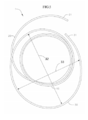
[0025] A figura 3 ilustra uma vista em perspectiva de uma âncora espiralada, de acordo com uma primeira modalidade da invenção;[0025] Figure 3 illustrates a perspective view of a spiral anchor, according to a first embodiment of the invention;
[0026] A figura 4 ilustra uma vista lateral da âncora espiralada da figura 3;[0026] Figure 4 shows a side view of the spiral anchor in figure 3;
[0027] A figura 5 ilustra uma vista superior da âncora espiralada das figuras 3 e 4;[0027] Figure 5 illustrates a top view of the spiral anchor of figures 3 and 4;
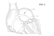
[0028] A figura 6 ilustra uma vista transversal de uma parte de um coração, durante uma etapa de distribuição da âncora espiralada, das figuras de 3 a 5, para o anel mitral nativo;[0028] Figure 6 shows a cross-sectional view of part of a heart, during a distribution step of the spiral anchor, of figures 3 to 5, for the native mitral ring;
[0029] A figura 7 ilustra uma vista transversal de uma parte de um coração, durante uma etapa adicional de distribuição da âncora espiralada, das figuras de 3 a 5, para o anel mitral nativo;[0029] Figure 7 illustrates a cross-sectional view of part of a heart, during an additional stage of distribution of the spiral anchor, of figures 3 to 5, to the native mitral ring;
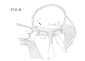
[0030] A figura 8 ilustra uma vista transversal de uma parte de um coração com a âncora espiralada, das figuras de 3 a 5, posicionada no anel mitral nativo;[0030] Figure 8 illustrates a cross-sectional view of a part of a heart with the spiral anchor, of figures 3 to 5, positioned in the native mitral ring;
[0031] A figura 9 ilustra uma vista transversal de uma parte de um coração com a âncora espiralada, das figuras de 3 a 5, e uma válvula mitral protética implantada no anel mitral nativo;[0031] Figure 9 illustrates a cross-sectional view of a part of a heart with the spiral anchor, figures 3 to 5, and a prosthetic mitral valve implanted in the native mitral ring;
[0032] A figura 10 ilustra uma vista em perspectiva de uma versão modificada da âncora espiralada das figuras de 3 a 5;[0032] Figure 10 illustrates a perspective view of a modified version of the spiral anchor of figures 3 to 5;
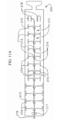
[0033] A figura 11 ilustra de forma esquemática uma vista aberta de um tubo de corte a laser a ser utilizado como uma âncora espiralada, de acordo com uma modalidade da invenção;[0033] Figure 11 schematically illustrates an open view of a laser cutting tube to be used as a spiral anchor, according to an embodiment of the invention;
[0034] A figura 11A ilustra de forma esquemática uma vista aberta de um tubo de corte a laser a ser utilizado como uma âncora espiralada e um fio de tensionamento de acordo com uma modalidade da invenção;[0034] Figure 11A schematically illustrates an open view of a laser cutting tube to be used as a spiral anchor and a tensioning wire according to an embodiment of the invention;
[0035] A figura 12 ilustra uma vista superior da âncora espiralada de corte a laser da figura 11 em um estado montado;[0035] Figure 12 illustrates a top view of the spiral laser anchor of figure 11 in an assembled state;
[0036] A figura 13 ilustra uma vista em perspectiva da âncora espiralada de corte a laser da figura 11 em um estado montado e acionado, e com a estrutura de uma válvula protética mantida aí;[0036] Figure 13 illustrates a perspective view of the laser cut spiral anchor of figure 11 in an assembled and actuated state, and with the structure of a prosthetic valve kept there;
[0037] A figura 14 ilustra uma vista superior de uma âncora espiralada modificada com os ganchos de extremidade;[0037] Figure 14 illustrates a top view of a modified spiral anchor with the end hooks;
[0038] A figura 15 ilustra uma vista esquemática de outra âncora espiralada modificada com uma camada de cobertura de alta fricção;[0038] Figure 15 illustrates a schematic view of another modified spiral anchor with a high friction covering layer;
[0039] A figura 16 ilustra uma vista esquemática de outra âncora espiralada modificada com os elementos de fricção;[0039] Figure 16 illustrates a schematic view of another spiral anchor modified with the friction elements;
[0040] A figura 16A ilustra uma vista transversal da modalidade ilustrada na figura 16;[0040] Figure 16A illustrates a cross-sectional view of the embodiment illustrated in figure 16;
[0041] A figura 17 ilustra uma vista esquemática de uma âncora espiralada incorporando ambos um elemento de fricção e cobertura de alta fricção;[0041] Figure 17 illustrates a schematic view of a spiral anchor incorporating both a friction element and a high friction cover;
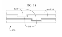
[0042] A figura 18 ilustra outra âncora espiralada modificada com características de superfície para facilitar o intertravamento ou retenção de posição entre os espirais adjacentes;[0042] Figure 18 illustrates another modified spiral anchor with surface characteristics to facilitate interlocking or retaining position between adjacent spirals;
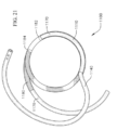
[0043] A figura 19 ilustra uma âncora espiralada ilustrativa que é uma variação da âncora espiralada da figura 10;[0043] Figure 19 illustrates an illustrative spiral anchor which is a variation of the spiral anchor of figure 10;
[0044] A figura 19A ilustra uma vista transversal de uma modalidade da âncora espiralada;[0044] Figure 19A illustrates a cross-sectional view of a spiral anchor modality;
[0045] A figura 20 ilustra esquematicamente uma vista superior de uma modalidade de uma âncora espiralada implantada e disposta em uma posição desejada no anel mitral nativo;[0045] Figure 20 schematically illustrates a top view of a modality of a spiral anchor implanted and arranged in a desired position in the native mitral ring;
[0046] A figura 21 ilustra a âncora espiralada da figura 19 incluindo adicionalmente bandas de marcador;[0046] Figure 21 illustrates the spiral anchor of figure 19 additionally including marker bands;
[0047] A figura 22 ilustra uma seção transversal de uma extremidade proximal da âncora espiralada da figura 19;[0047] Figure 22 illustrates a cross section of a proximal end of the spiral anchor in figure 19;
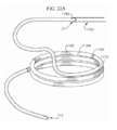
[0048] A figura 22A ilustra uma modalidade de uma sutura envolvida através de uma âncora espiralada;[0048] Figure 22A illustrates a modality of a suture wrapped through a spiral anchor;
[0049] A figura 22B ilustra uma outra modalidade de uma sutura envolvida através de uma âncora espiralada;[0049] Figure 22B illustrates another modality of a suture wrapped through a spiral anchor;
[0050] A figura 22C ilustra uma modalidade de uma sutura envolvida através de uma âncora espiralada;[0050] Figure 22C illustrates a modality of a suture wrapped through a spiral anchor;
[0051] A figura 23 ilustra uma extremidade distal de um esqueleto de espiral ou núcleo de um dispositivo de atracação, de acordo com uma modalidade da invenção;[0051] Figure 23 illustrates a distal end of a spiral skeleton or core of a mooring device, according to an embodiment of the invention;
[0052] A figura 24 ilustra uma extremidade distal de um esqueleto de espiral ou núcleo de um dispositivo de atracação, de acordo com outra modalidade da invenção;[0052] Figure 24 illustrates a distal end of a spiral skeleton or core of a mooring device, according to another embodiment of the invention;
[0053] A figura 25 ilustra uma extremidade proximal de um esqueleto de espiral ou núcleo de um dispositivo de atracação, de acordo com uma modalidade da invenção; e[0053] Figure 25 illustrates a proximal end of a spiral skeleton or core of a mooring device, according to an embodiment of the invention; and
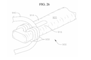
[0054] A figura 26 ilustra uma extremidade proximal do dispositivo de atracação da figura 25, com uma camada de cobertura fixada sobre o esqueleto de espiral ou núcleo.[0054] Figure 26 illustrates a proximal end of the mooring device of figure 25, with a covering layer fixed over the spiral skeleton or core.
[0055] São descritos aqui vários dispositivos de atracação ou ancoragem espiralados, que podem ser utilizados em conjunto com válvulas cardíacas transcateter expansíveis (THV) em um anel valvular nativo (por exemplo, anel de válvula mitral ou tricúspide), a fim de implantar de forma mais segura e manter a válvula protética no local do implante. Dispositivos de ancoragem/atracação, de acordo com as modalidades da invenção, fornecem ou formam um anel mais circular e/ou estável no local de implante, onde as válvulas protéticas possuem estruturas de válvula de formato cilíndrico ou stents podem ser expandidos ou de outra forma implantados. Em adição ao fornecimento de um local de ancoragem para a válvula protética, os dispositivos de ancoragem/atracação podem ser dimensionados e formatados para apertar ou puxar a anatomia da válvula nativa (por exemplo, mitral, tricúspide, etc.), de forma radial, para dentro. Dessa forma, uma das causas principais de regurgitação de válvula (por exemplo, regurgitação mitral funcional), especificamente o aumento do coração (por exemplo, ventrículo esquerdo) e/ou anel de válvula, e o estiramento consequente do anel de válvula nativa (por exemplo, mitral), pode ser pelo menos parcialmente desviada ou reagida. Algumas modalidades dos dispositivos de ancoragem ou atracação incluem adicionalmente acessórios que, por exemplo, são formatados e/ou modificados para manter melhor uma posição ou formato do dispositivo de atracação durante e/ou depois da expansão de uma válvula protética. Pelo fornecimento de tais dispositivos de ancoragem ou atracação, válvulas de substituição podem ser implantadas e mantidas mais facilmente em vários anéis de válvula, incluindo no anel mitral que não possui uma seção transversal naturalmente circular.[0055] Various spiral mooring or anchoring devices are described here, which can be used in conjunction with expandable transcatheter heart valves (THV) in a native valve ring (for example, mitral or tricuspid valve ring), in order to implant safer way and keep the prosthetic valve at the implant site. Anchoring / mooring devices, according to the modalities of the invention, provide or form a more circular and / or stable ring at the implantation site, where the prosthetic valves have cylindrical shaped valve structures or stents can be expanded or otherwise implanted. In addition to providing an anchorage for the prosthetic valve, the anchoring / mooring devices can be sized and shaped to tighten or pull the anatomy of the native valve (eg mitral, tricuspid, etc.), radially, inside. Thus, one of the main causes of valve regurgitation (for example, functional mitral regurgitation), specifically the enlargement of the heart (for example, left ventricle) and / or valve ring, and the consequent stretching of the native valve ring (for example, example, mitral), can be at least partially diverted or reacted. Some modalities of the anchoring or mooring devices additionally include accessories that, for example, are shaped and / or modified to better maintain a position or shape of the mooring device during and / or after the expansion of a prosthetic valve. By providing such anchoring or mooring devices, replacement valves can be more easily implanted and maintained in various valve rings, including the mitral ring that does not have a naturally circular cross section.
[0056] Um dispositivo de ancoragem/atracação em formato de espiral, de acordo com uma modalidade ilustrativa da invenção, é ilustrada nas figuras de 3 a 5. A figura 3 ilustra uma vista em perspectiva da âncora ou dispositivo de atracação 1, a figura 4 ilustra uma vista lateral do dispositivo de ancoragem/atracação 1 e a figura 5 ilustra uma vista superior do dispositivo de ancoragem/atracação 1.[0056] A spiral anchoring / mooring device, according to an illustrative embodiment of the invention, is illustrated in figures 3 to 5. Figure 3 illustrates a perspective view of the anchor or
[0057] O dispositivo de atracação 1 inclui um espiral com uma pluralidade de voltas se estendendo ao longo de um eixo geométrico central do dispositivo de atracação 1. O espiral pode ser contínuo e pode se estender geralmente de forma helicoidal, com várias seções dimensionadas e formatadas diferentemente, como descrito em maiores detalhes abaixo. O dispositivo de atracação 1 ilustrado nas figuras de 3 a 5 é configurado para melhor encaixar na posição mitral, mas pode ser formatado de forma similar ou diferente em outras modalidades para uma melhor acomodação em outras posições de válvula nativa, também.[0057] The
[0058] O dispositivo de atracação 1 inclui uma região central 10 com aproximadamente três voltas totalmente espiraladas possuindo, substancialmente, diâmetros internos iguais. A região centralizada 10 do dispositivo de atracação 1 serve como a região de aterrissagem principal ou região de retenção para reter a válvula protética expansível ou THV quando o dispositivo de atracação 1 e a prótese de válvula são implantados no corpo de um paciente. Outras modalidades do dispositivo de atracação 1 podem apresentar uma região central 10 com mais ou menos do que três voltas espiraladas, dependendo, por exemplo, da anatomia do paciente, da quantidade de contato vertical desejado entre o dispositivo de atracação 1 e a prótese de válvula (por exemplo, THV) e/ou outros fatores. Os espirais da região central 10 também podem ser referidos como "espirais funcionais", visto que as propriedades desses espirais contribuem ao máximo para a quantidade de força de retenção gerada entre a prótese de válvula, o dispositivo de atracação 1, e as cúspides mitrais nativas e/ou outras estruturas anatômicas.[0058] The
[0059] Vários fatores podem contribuir para a força de retenção total entre o dispositivo de atracação 1 e a válvula protética mantida aí. Um fator principal é o número de voltas incluídas nos espirais funcionais, enquanto outros fatores incluem, por exemplo, um diâmetro interno dos espirais funcionais, uma força de fricção entre os espirais e a válvula protética, e a resistência da válvula protética e a força radial da válvula são aplicadas ao espiral. Um dispositivo de atracação pode ter uma variedade de números de voltas espiraladas. O número de voltas funcionais pode estar nas faixas de apenas um pouco além de uma meia volta até 5 voltas, ou uma volta inteira até 5 voltas, ou mais. Em uma modalidade com três voltas inteiras, uma meia volta adicional é incluída na parte ventricular do dispositivo de atracação. Em outra modalidade, pode haver três voltas inteiras totais no dispositivo de atracação. Em uma modalidade, na parte atrial do dispositivo de atracação, pode haver uma meia volta até três quartos de volta ou metade a três quartos de um círculo. Enquanto uma faixa de voltas é fornecida, à medida que o número de voltas em um dispositivo de atracação é reduzido, as dimensões e/ou materiais do espiral e/ou do fio do qual o espiral é feito também podem mudar para manter uma força de retenção adequada. Por exemplo, o diâmetro do fio pode ser maior e/ou o diâmetro das voltas de espiral de função em um dispositivo de atracação com menos espirais. Pode haver uma pluralidade de espirais no átrio e no ventrículo.[0059] Several factors can contribute to the total holding force between the
[0060] Um tamanho dos espirais funcionais ou espirais da região central 10 é geralmente selecionado com base no tamanho da THV desejado a ser implantado dentro do paciente. Geralmente, o diâmetro interno dos espirais/voltas funcionais (por exemplo, dos espirais/voltas da região central 10 do dispositivo de atracação 1) será menor do que o diâmetro externo da válvula cardíaca expansível, de modo que quando a válvula protética é expandida no dispositivo de atracação, uma tensão radial ou força de retenção adicional agirá entre o dispositivo de atracação e a válvula protética para manter a válvula protética no lugar. A força de retenção necessária para o implante adequado de uma válvula protética varia com base no tamanho da válvula protética e com base na habilidade de o conjunto manusear as pressões mitrais de aproximadamente 180 mm Hg. Por exemplo, com base em estudos de bancada utilizando uma válvula protética com um diâmetro externo expandido de 29 mm, uma força de retenção de pelo menos 18,5 N é necessária entre o dispositivo de atracação e a válvula protética a fim de manter de forma segura a válvula protética no dispositivo de atracação e resistir ou evitar a regurgitação mitral ou vazamento. No entanto, sob esse exemplo, para se corresponder a essa exigência de força de retenção de 18,5 N com confiabilidade estatística, uma força de retenção média alvo deve ser substancialmente maior, por exemplo, de aproximadamente 30 N.[0060] A size of the functional spirals or central region spirals 10 is generally selected based on the size of the desired THV to be implanted within the patient. Generally, the inner diameter of the coils / functional turns (for example, the coils / turns of the
[0061] Em muitas modalidades, a força de retenção entre o dispositivo de atracação e a prótese valvular reduz drasticamente quando uma diferença entre o diâmetro externo da válvula protética em seu estado expandido e o diâmetro interno dos espirais funcionais é inferior a cerca de 5 mm, visto que o diferencial de tamanho reduzido seria muito pequeno para criar uma força de retenção suficiente entre os componentes. Por exemplo, quando, como em uma modalidade, uma válvula protética com um diâmetro externo de 29 mm expandido é expandida em um conjunto de espirais com um diâmetro interno de 24 mm, a força de retenção observada é de cerca de 30 N, mas quando a mesma válvula protética é expandida em um conjunto de espirais com um diâmetro interno de 25 mm (por exemplo, apenas 1 mm maior), a força de retenção observada cai de forma significativa para apenas 20 N. Portanto, para válvulas e dispositivos de atracação desse tipo, a fim de se criar uma força de retenção suficiente entre o dispositivo de atracação e uma válvula protética de 29 mm, o diâmetro interno dos espirais funcionais (por exemplo, bobinas da região central 10 do dispositivo de atracação 1) devem ter 24 mm ou menos. Geralmente, o diâmetro interno dos espirais funcionais (por exemplo, região central 10 do dispositivo de rastreamento 1) deve ser selecionado para que tenha pelo menos cerca de 5 mm a menos do que a válvula protética que é selecionada para implante, apesar de outros acessórios e/ou características (por exemplo, acessórios de melhoria de fricção, características de material, etc.) poderem ser utilizados para fornecer uma melhor retenção se outros tamanhos ou faixas de tamanho forem utilizadas, visto que os vários fatores podem afetar a força de retenção. Adicionalmente, um tamanho do diâmetro interno dos espirais funcionais ou região central 10 pode ser selecionado para unir a anatomia mitral, a fim de desviar, pelo menos parcialmente, ou reagir à regurgitação mitral que é causada pelo estiramento do anel valvular nativo como resultado, por exemplo, do aumento ventricular esquerdo.[0061] In many modalities, the holding force between the mooring device and the valve prosthesis drastically reduces when a difference between the outer diameter of the prosthetic valve in its expanded state and the inner diameter of the functional spirals is less than about 5 mm , since the small size differential would be too small to create sufficient holding force between components. For example, when, as in a modality, a prosthetic valve with an expanded outer diameter of 29 mm is expanded into a set of coils with an inner diameter of 24 mm, the observed holding force is about 30 N, but when the same prosthetic valve is expanded into a set of coils with an internal diameter of 25 mm (for example, only 1 mm larger), the observed holding force drops significantly to just 20 N. Therefore, for valves and mooring devices of this type, in order to create sufficient holding force between the mooring device and a 29 mm prosthetic valve, the inner diameter of the functional spirals (for example, coils of the
[0062] É notado que as forças de retenção desejadas, discutidas acima, são aplicáveis às modalidades para substituições de válvula mitral. Portanto, outras modalidades do dispositivo de atracação que são utilizadas para substituir outras válvulas podem ter diferentes relações de tamanho com base nas forças de retenção desejadas para substituição de válvula nessas posições respectivas. Adicionalmente, os diferenciais de tamanho também podem variar, por exemplo, com base nos materiais utilizados para a válvula e/ou o dispositivo de atracação, onde existem outros acessórios para evitar a expansão dos espirais funcionais ou para melhorar a fricção/travamento, e/ou com base em vários outros fatores.[0062] It is noted that the desired retention forces, discussed above, are applicable to the modalities for mitral valve replacements. Therefore, other modalities of the mooring device that are used to replace other valves may have different size ratios based on the desired holding forces for replacing the valve in those respective positions. In addition, the size differentials may also vary, for example, based on the materials used for the valve and / or the mooring device, where other accessories exist to prevent the expansion of the functional spirals or to improve friction / locking, and / or based on several other factors.
[0063] Nas modalidades onde o dispositivo de atracação 1 é utilizado na posição mitral, o dispositivo de atracação pode ser primeiramente avançado e distribuído para o anel de válvula mitral nativa, e, então, configurado em uma posição desejada, antes da implantação da THV. Preferivelmente, o dispositivo de atracação 1 é flexível e/ou feito de um material de efeito memória, de modo que os espirais do dispositivo de atracação 1 possam ser endireitados para distribuição através de uma abordagem de transcateter também. Em outra modalidade, o espiral pode ser feito de outro material biocompatível, tal como aço inoxidável. Alguns dos outros cateteres e outras ferramentas de distribuição podem ser utilizados para distribuição do dispositivo de atracação 1 e a válvula protética, sem precisar realizar etapas preparatórias separadas, simplificando o procedimento de implantação para o usuário final.[0063] In the modalities where the
[0064] O dispositivo de atracação 1 pode ser distribuído para a posição mitral de forma transatrial, a partir do átrio esquerdo, de forma transeptal através do septo atrial, ou pode ser distribuído para a posição mitral através de um dos vários outros pontos de acesso ou procedimentos conhecidos. As figuras 6 e 7 ilustram algumas etapas durante a distribuição de um dispositivo de atracação 1 para a posição mitral utilizando uma abordagem transeptal, onde uma bainha guia 1000 é avançada através da vasculatura para o átrio direito e através do septo atrial do coração para o átrio esquerdo, e um cateter de distribuição 1010 é avançado através da bainha guia 1000 passando através da vasculatura, átrio direito, e septo para dentro do átrio esquerdo. Como pode ser mais bem observado na figura 6, o dispositivo de atracação 1 pode ser avançado através de uma extremidade distal do cateter de distribuição 1010 posicionado no átrio esquerdo (por exemplo, posicionado em uma comissura), através do anel mitral nativo, por exemplo, em uma comissura da válvula mitral nativa, e para dentro do ventrículo esquerdo. A extremidade distal do dispositivo de atracação 1, então, circula a anatomia mitral (por exemplo, cúspides mitrais nativas e/ou cordas tendíneas) localizada no ventrículo esquerdo, de modo que todas ou pelo menos algumas das cúspides nativas e/ou cordas tendíneas sejam encurralados ou agrupados e mantidos (por exemplo, circundados por) pelos espirais do dispositivo de atracação 1.[0064] The
[0065] No entanto, visto que os espirais/voltas funcionais ou espirais/voltas da região central 10 do dispositivo de atracação 1 são mantidos relativamente pequenos em termos de diâmetro (por exemplo, a região central 10 em uma modalidade pode apresentar um diâmetro interno de aproximadamente 24 mm (por exemplo, +/- 2 mm) ou outro diâmetro menor do que THV e/ou o anel nativo) a fim de aumentar a força de retenção com a válvula protética, pode ser difícil se avançar o dispositivo de atracação 1 em torno das cúspides existentes e/ou chordae para uma posição desejada com relação ao anel mitral nativo. Isso é especialmente verdadeiro se todo o dispositivo de atracação 1 for feito para que tenha o mesmo diâmetro pequeno que a região central 10. Portanto, com referência novamente às figuras de 3 a 5, o dispositivo de atracação 1 pode ter uma região distal ou inferior 20 que cria um espiral/volta dianteiro (ou espiral/volta ventricular dianteiro) do dispositivo de atracação 1, que possui um diâmetro que é superior ao diâmetro de espirais/voltas funcionais dos espirais/voltas da região central 10.[0065] However, since the functional coils / turns or coils / turns of the
[0066] Acessórios da anatomia mitral no ventrículo esquerdo possuem dimensões variáveis, e podem possuir uma largura maior de aproximadamente 35 a 45 mm em um eixo geométrico longo. O diâmetro ou largura do espiral/volta dianteiro (por exemplo, espiral/volta ventricular) da região inferior 20 pode, portanto, ser selecionado para ser maior para que se navegue com mais facilidade uma ponta distal ou dianteira 21 do dispositivo de atracação 1 em torno de, e circunde, os acessórios da anatomia mitral (por exemplo, cúspides e/ou cordas tendíneas). Vários tamanhos e formatos são possíveis, por exemplo, em uma modalidade, o diâmetro pode ser de qualquer tamanho de 25 mm a 75 mm. O termo "diâmetro" como utilizado nessa descrição não exige que um espiral/volta seja um círculo completo ou perfeito, mas é geralmente utilizado para referir a uma largura maior através de pontos opostos do espiral/volta. Por exemplo, com relação ao espiral/volta dianteiro, o diâmetro pode ser medido a partir da ponta distal 21 para o lado oposto, como se a região inferior 20 ou o espiral/volta dianteiro formasse uma rotação completa, ou o diâmetro pode ser considerado o dobro de um raio de curvatura do espiral/volta dianteiro. Em uma modalidade, a região inferior 20 do dispositivo de atracação 1 (por exemplo, espiral/volta dianteiro) possui um diâmetro (por, exemplo,) de aproximadamente 43 mm (por exemplo, +/- 2 mm), em outras palavras, o raio de curvatura no espiral/volta dianteiro pode ser de aproximadamente 21,5 mm. Ter o espiral/volta dianteiro com um tamanho maior do que o dos espirais funcionais pode ajudar a orientar com mais facilidade os espirais em torno e/ou através da geometria de chordae, e, mais importante, adequadamente em torno de cúspides nativas da válvula mitral. Uma vez que a ponta distal 21 é navegada em torno da anatomia mitral desejada, os espirais restantes do dispositivo de atracação 1 também podem ser orientados em torno dos mesmos acessórios, onde o tamanho reduzido dos outros espirais pode fazer com que acessórios anatômicos encurralados sejam puxados ligeiramente de forma radial, para dentro. Enquanto isso, o comprimento da região inferior aumentada 20 é geralmente mantido relativamente curto, para evitar obstrução ou interferência do fluxo sanguíneo ao longo do trato de fluxo de saída ventricular esquerdo pela região inferior 20. Por exemplo, em uma modalidade, a região inferior ampliada 20 se estende por apenas cerca de metade de uma alça ou rotação. Com uma região inferior 20 possuindo esse comprimento relativamente curto, quando uma válvula protética é expandida para dentro do dispositivo de atracação 1 e os espirais do dispositivo de atracação 1 começam a desenrolar ligeiramente devido ao diferencial de tamanho entre o dispositivo de atracação e a válvula protética, a região inferior 20 também pode ser puxada para dentro e alterada ligeiramente. Sob esse exemplo, depois da expansão da válvula protética, a região inferior 20 pode ser similar em tamanho e alinhada substancialmente com os espirais funcionais do dispositivo de atracação 1, em vez de continuar a se projetar para longe dos espirais funcionais, reduzindo, assim, quaisquer distúrbios de fluxo em potencial. Outras modalidades de dispositivo de atracação podem ter regiões inferiores que são mais longas ou mais curtas, dependendo da aplicação em particular.[0066] Mitral anatomy accessories in the left ventricle have variable dimensions, and can have a width greater than approximately 35 to 45 mm on a long geometric axis. The diameter or width of the front spiral / lap (for example, ventricular spiral / lap) of the
[0067] O dispositivo de atracação 1 nas figuras de 3 a 5 também inclui uma região proximal ou superior ampliada 30 que cria um espiral/volta de estabilização (por exemplo, que pode ser um espiral/volta atrial) do dispositivo de atracação 1. Quando o dispositivo de atracação 1 foi colocado em uma posição desejada e na orientação no anel mitral nativo, todo o dispositivo de atracação 1 é liberado do cateter de distribuição 1010, e, depois disso, uma válvula protética (por exemplo, uma THV) é distribuída para o dispositivo de atracação 1. Durante um estágio transiente ou intermediário do procedimento de implantação, isso é, durante o tempo entre o desdobramento e a liberação do dispositivo de atracação 1 e a distribuição final da válvula protética, existe uma possibilidade de o espiral poder ser alterado e/ou desalojado de sua posição ou orientação desejada, por exemplo, pela função cardíaca regular. A alteração do dispositivo de atracação 1 pode levar, potencialmente, a uma implantação menos segura, falta de alinhamento e/ou problemas de posicionamento para a válvula protética. Um acessório de estabilização ou espiral pode ser utilizado para ajudar a estabilizar o dispositivo de atracação na posição desejada. Por exemplo, o dispositivo de atracação 1 pode incluir a região superior 30 com um espiral/volta de estabilização aumentado (por exemplo, espiral/volta atrial aumentado) que deve ser posicionado no sistema circulatório (por exemplo, no átrio esquerdo), de modo que possa estabilizar o dispositivo de atracação. Por exemplo, a região superior 30 ou espiral/volta de estabilização pode ser configurado para apoiar ou empurrar as paredes do sistema circulatório (por exemplo, contra as paredes do átrio esquerdo), a fim de aperfeiçoar a capacidade de o dispositivo de atracação 1 em permanecer em sua posição desejada antes do implante da válvula protética.[0067] The
[0068] O espiral/volta de estabilização (por exemplo, espiral/volta atrial) na região superior 30 do dispositivo de atracação 1 na modalidade ilustrada se estende por cerca de ou quase que uma volta inteira ou rotação, e termina em uma ponta proximal 31. Em outras modalidades, o espiral/volta de estabilização (por exemplo, espiral atrial) pode se estender por mais ou menos do que uma volta ou rotação, dependendo, por exemplo, da quantidade de contato desejado entre o dispositivo de atracação e o sistema circulatório (por exemplo, com as paredes do átrio esquerdo) em cada aplicação particular. O tamanho radial do espiral/volta de estabilização (por exemplo, espiral atrial) na região superior 30 também pode ser significativamente maior do que o tamanho dos espirais funcionais na região central 10, de modo que o espiral/volta de estabilização (por exemplo, espiral atrial) se alargue ou se estenda suficientemente para fora a fim de fazer contato com as paredes do sistema circulatório (por exemplo, as paredes do átrio esquerdo). Por exemplo, em uma modalidade, um diâmetro principal 32 ou largura da região superior 30 é de aproximadamente 50 mm (por exemplo, +/- 2 mm), ou cerca do dobro do tamanho dos espirais na região central 10. Uma região inferior do átrio esquerdo estreita geralmente na direção do anel mitral nativo. Portanto, quando o dispositivo de atracação 1 é adequadamente desenvolvido na posição mitral, o espiral/volta de estabilização (por exemplo, espiral atrial) da região superior 30 assenta e empurra as paredes do átrio esquerdo, para ajudar a manter o dispositivo de atracação 1 em uma posição e orientação desejadas relativamente altas e impedindo ou reduzindo a mudança do dispositivo de atracação 1 na direção do ventrículo esquerdo, até que THV seja avançada para e expandida no dispositivo de atracação 1. Uma vez que a válvula protética (por exemplo, THV) é expandida dentro do dispositivo de atracação, a força gerada entre os espirais funcionais e a válvula protética (por exemplo, com tecido, cúspides, etc. entre os mesmos) é suficiente para prender e estabilizar o dispositivo de atracação e a válvula protética sem precisar do espiral/volta de estabilização.[0068] The stabilizing spiral / loop (for example, spiral / atrial loop) in the
[0069] Opcionalmente, o espiral/volta de estabilização (por exemplo, espiral atrial) da região superior 30 pode ser não circular em formato e, na modalidade ilustrada, é orientado e disposto em um formato elíptico ou ovoide. Como ilustrado na figura 5, um espiral/volta de estabilização de formato elíptico ou outro formato não circular (por exemplo, espiral atrial) pode ter um diâmetro de eixo geométrico principal 32, D1 (isso é, uma largura maior da volta de espiral) e um diâmetro de eixo geométrico menor 33, D2 (isso é, uma largura de extremidade para extremidade menor). As larguras/diâmetros podem ser escolhidos com base no tamanho da anatomia de uma parte de um sistema circulatório (por exemplo, com base no tamanho do átrio esquerdo humano). O diâmetro de eixo geométrico principal (ou largura maior), D1, pode variar de 40 a 100 mm, ou pode ser de 40 a 80 mm, ou de 40 a 75 mm. O diâmetro de eixo geométrico menor (ou largura menor) D2 pode variar de 20 a 80 mm, ou de 20 a 75 mm. Enquanto um diâmetro/largura maior D1 do espiral/volta de estabilização (por exemplo, espiral atrial) pode ser de aproximadamente 50 mm, um diâmetro/largura D2 ao longo de um eixo geométrico menor do espiral/volta de estabilização (por exemplo, espiral atrial) pode ser muito menor, por exemplo, apenas ligeiramente maior do que o diâmetro da região central 10 do dispositivo de atracação 1, como pode ser mais bem observado na vista superior do dispositivo de atracação 1 na figura 5. Em outras modalidades, a orientação da região superior do dispositivo de atracação pode ser realizada de outras formas. Por exemplo, o espiral/volta de estabilização (por exemplo, espiral atrial) da região superior 30 ainda pode ser substancialmente circular, e/ou o espiral/volta de estabilização pode ser orientado em uma direção, de modo que um centro da região superior seja desviado do centro de outras partes do dispositivo de atracação. Essa orientação de formato da região superior 30 do dispositivo de atracação 1 pode, por exemplo, aumentar o contato entre o dispositivo de atracação 1 e a parede do átrio esquerdo ou outra anatomia na direção radial, na qual a região superior 30 se estende mais para longe das outras partes do dispositivo de atracação 1. O espiral/volta de estabilização (por exemplo, espiral atrial) pode ser orientado de modo que quando observado a partir de uma vista superior (figura 20), o espiral/volta de estabilização (por exemplo, espiral atrial) possua um centro que é desviado do centro dos espirais funcionais por cerca de 50 a 75% do diâmetro das voltas funcionais. A volta de estabilização (por exemplo, volta atrial) do espiral pode ser flexível e flexionar para dentro. Isso acomoda a anatomia (por exemplo, anatomia de átrio esquerdo) onde o espiral/volta de estabilização (por exemplo, espiral atrial) pode apresentar um diâmetro de eixo geométrico maior ou menor que é maior do que o átrio ou outra anatomia propriamente dita.[0069] Optionally, the stabilizing spiral / turn (for example, atrial spiral) of the
[0070] Importante, o dispositivo de atracação 1 pode ser girado ou de outra forma orientado de modo que a parte mais estreita da região superior 30, ou a parte que se estende pelo menos radialmente para fora, seja direcionada de uma forma ideal. Por exemplo, quando implantado em uma válvula mitral nativa, na direção da parede do átrio esquerdo que se opõe ou empurra o trato de fluxo de saída ventricular esquerdo, de modo que a quantidade de pressão aplicada pelo dispositivo de atracação 1 contra essa parte da parede atrial seja reduzida. Dessa forma, uma quantidade de deslocamento dessa parte da parede para dentro do trato de fluxo de saída ventricular esquerdo também será reduzida, e a região superior aumentada 30 pode, portanto, evitar obscurecer, interferir com ou afetar de outra forma o fluxo sanguíneo através do trato de fluxo de saída ventricular esquerdo.[0070] Importantly, the
[0071] Com a região superior aumentada 30, o dispositivo de atracação 1 pode ser mantido ou retido de forma mais segura em um posicionamento e orientação adequados no anel de válvula nativa (por exemplo, anel mitral nativo) antes de THV ser implantada e expandida. Tal auto retenção do dispositivo de atracação 1 impedirá de forma mais eficiente a alteração ou inclinação indesejável do dispositivo de atracação 1 antes de a válvula protética ser completamente implantada, aperfeiçoando, assim, o desempenho do implante como um todo.[0071] With the augmented
[0072] As figuras de 6 a 9 ilustram algumas das etapas que podem ser utilizadas para distribuir e implantar um dispositivo de atracação (por exemplo, o dispositivo de atracação 1 ou outros dispositivos de atracação descritos em outro lugar aqui) e uma THV na posição mitral. Enquanto focam na posição mitral, etapas similares podem ser utilizadas em outras localizações de válvula, por exemplo, na posição da válvula tricúspide. O dispositivo de atracação pode ser o dispositivo de atracação 1 descrito acima com relação às figuras de 3 a 5 ou outro dispositivo de atracação similar (por exemplo, outros dispositivos de atracação), e THV é geralmente uma THV de expansão automática, de expansão mecânica ou de expansão com balão (ou uma combinação dos mesmos) com uma estrutura de válvula circular ou cilíndrica ou stent que é dimensionado para ser expandido e mantido no dispositivo de atracação.[0072] Figures 6 to 9 illustrate some of the steps that can be used to distribute and deploy a mooring device (for example,
[0073] As figuras 6 e 7 ilustram um procedimento transeptal para distribuir o dispositivo de atracação 1 para a posição mitral do paciente, onde uma bainha guia/introdutor 1000 é avançado através do septo atrial do coração e uma extremidade distal de um cateter de distribuição 1010 é avançada através da bainha guia 1000 e posicionada com uma abertura distal do cateter de distribuição posicionada no átrio esquerdo para distribuir o dispositivo de atracação 1. Opcionalmente, um cateter de distribuição pode ser avançado de forma similar através da anatomia (por exemplo, vasculatura, câmaras do coração, septo, etc.) e posicionado de forma similar sem primeiro inserir ou utilizar uma bainha guia. Em um procedimento ilustrativo, a bainha guia 1000 (e/ou o cateter de distribuição 1010) é introduzida no sistema venoso do paciente por perfuração percutânea ou por um corte cirúrgico pequeno, por exemplo, na virilha do paciente, e, então, a bainha guia 1000 (e/ou cateter 1010) é avançada através da vasculatura do paciente até o átrio esquerdo como ilustrado nas figuras 6 e 7. É notado que o procedimento transeptal ilustrado é apenas um exemplo, e vários procedimentos e/ou locais de acesso alternativos podem, em vez disso, ser utilizados para distribuir o dispositivo de atracação 1 e/ou uma válvula protética adequada para a posição mitral ou para outras posições do coração. No entanto, um procedimento transatrial ou transeptal pode ser preferível, visto que tais procedimentos fornecem uma entrada mais limpa no lado esquerdo do coração quando comparados, por exemplo, com um procedimento transapical ou outro procedimento onde o acesso à válvula mitral se dá através do ventrículo esquerdo, de modo que o médico pode evitar a interferência direta com cordas tendíneas e outros obstáculos ventriculares.[0073] Figures 6 and 7 illustrate a transeptal procedure for distributing the
[0074] Como ilustrado na figura 6, o cateter de distribuição 1010 é avançado para uma posição no átrio esquerdo onde a extremidade distal do cateter de distribuição 1010 está acima de um plano da válvula nativa (por exemplo, o plano mitral) e pode ser posicionada, por exemplo, perto de uma comissura da válvula nativa. O cateter de distribuição pode ser direcionável em múltiplas dimensões (por exemplo, mais de duas dimensões) para permitir um posicionamento mais preciso. O posicionamento da abertura distal do cateter de distribuição define um local de acesso para implantar o dispositivo de atracação 1 na posição mitral. O local de acesso é normalmente perto de uma das duas comissuras da válvula mitral nativa, de modo que a ponta dianteira 21 do dispositivo de atracação 1 possa ser avançada através da comissura de válvula nativa para dentro do ventrículo esquerdo, a fim de desdobrar o espiral/volta dianteiro (por exemplo, espiral ventricular) da região inferior 20, além de pelo menos parte dos espirais funcionais (por exemplo, espirais da região central 10), para dentro do ventrículo esquerdo. Em um método de desdobramento, a ponta dianteira 21 do dispositivo de atracação 1 é primeiramente passada através da comissura A3P3 da válvula mitral nativa, e, então, mais do dispositivo de atracação 1 é avançado para fora do cateter de distribuição através da comissura A3P3.[0074] As illustrated in figure 6, the
[0075] Enquanto o dispositivo de atracação 1 é mantido no cateter de distribuição 1010, o dispositivo de atracação 1 pode ser endireitado para ser manobrado com mais facilidade através do cateter de distribuição 1010. Depois disso, o dispositivo de atracação 1 é girado, empurrado ou de oura forma avançado para fora do cateter de distribuição 1010, o dispositivo de atracação 1 pode retornar para seu formato espiralado ou curvado original, e um avanço adicional do dispositivo de atracação 1 para fora do cateter de distribuição causa um avanço no sentido horário ou anti-horário (isso é, visualizando o anel na direção do fluxo de saída de sangue) da ponta dianteira 21 em torno (por exemplo, para circundar) de vários acessórios da anatomia mitral, com base na direção de curvatura do dispositivo de atracação 1 quando sai do cateter de distribuição. O espiral/volta dianteiro aumentado (por exemplo, espiral/volta ventricular) na região inferior 20 do dispositivo de atracação 1 torna a navegação da ponta dianteira 21 do dispositivo de atracação 1 em torno da anatomia mitral no ventrículo esquerdo mais fácil. No exemplo acima, quando a ponta dianteira 21 do dispositivo de atracação 1 entra no ventrículo esquerdo através da comissura A3P3 e é avançado no sentido horário observando o anel na direção de fluxo de saída (por exemplo, do átrio para o ventrículo), o dispositivo de atracação 1 pode primeiro contornar e encurralar a cúspide posterior da válvula mitral nativa. Métodos alternativos também estão disponíveis para encurralar a cúspide posterior primeiro, por exemplo, inserindo a ponta dianteira 21 através da comissura A1P1 e, então, avançando o dispositivo de atracação no sentido anti-horário.[0075] While the
[0076] Em algumas situações, encurralar a cúspide posterior da válvula mitral nativa pode, primeiramente, ser mais fácil do que encurralar a cúspide anterior primeiro, visto que a cúspide posterior é posicionada mais perto de uma parede ventricular que fornece um espaço mais confinado ao longo do qual a ponta dianteira 21 pode avançar. A ponta dianteira 21 do dispositivo de atracação 1 pode, portanto, utilizar a parede ventricular perto da cúspide posterior como um caminho ou guia para avanço em torno da cúspide posterior. Inversamente, quando se tenta avançar a ponta dianteira 21 do dispositivo de atracação 1 em torno de e para capturar a cúspide anterior da válvula mitral nativa primeiro, não existe parede ventricular próxima que possa facilitar ou orientar o avanço da ponta dianteira 21 nessa direção. Portanto, em algumas situações, pode ser mais difícil se iniciar adequadamente o englobamento da anatomia mitral quando se navega a ponta dianteira 21 para tentar primeiro capturar a cúspide anterior em vez da cúspide posterior.[0076] In some situations, cornering the posterior cusp of the native mitral valve may first be easier than cornering the anterior cusp first, since the posterior cusp is positioned closer to a ventricular wall that provides a more confined space to the over which the
[0077] Tendo dito isso, ainda pode ser preferível ou necessário, em alguns procedimentos, se encurralar a cúspide anterior primeiro. Adicionalmente, em muitas situações, também pode ser mais simples se dobrar a extremidade distal do cateter de distribuição 1010 em uma direção anti-horária na preparação para a distribuição do dispositivo de atracação. Como tal, o método de distribuição do dispositivo de atracação pode ser ajustado de acordo. Por exemplo, um dispositivo de atracação pode ser configurado com voltas espiraladas em uma direção anti-horária oposta (por exemplo, como observado na figura 10 abaixo), onde o cateter de distribuição 1010 também enrola em uma direção anti-horária. Dessa forma, tal dispositivo de atracação pode ser avançado, por exemplo, através da comissura A3P3 e para dentro do ventrículo esquerdo em uma direção anti-horária observando o anel em uma direção de fluxo de saída (por exemplo, átrio para ventrículo) em vez de na direção horária descrita acima.[0077] Having said that, it may still be preferable or necessary, in some procedures, to corner the anterior cusp first. In addition, in many situations, it can also be simpler to bend the distal end of the 1010 delivery catheter in a counterclockwise direction in preparation for the mooring device delivery. As such, the distribution method of the mooring device can be adjusted accordingly. For example, a mooring device can be configured with spiral turns in an opposite counterclockwise direction (for example, as seen in figure 10 below), where the 1010 delivery catheter also winds in a counterclockwise direction. In this way, such a mooring device can be advanced, for example, through the A3P3 commissure and into the left ventricle in a counterclockwise direction by looking at the ring in an outflow direction (for example, atrium to ventricle) instead in the clockwise direction described above.
[0078] Uma quantidade de dispositivo de atracação a ser avançado para dentro do ventrículo esquerdo depende da aplicação ou procedimento particular. Em uma modalidade, os espirais da região inferior 20, e a maior parte dos espirais da região central 10 (mesmo que nem todos) são avançados e posicionados no ventrículo esquerdo. Em uma modalidade, o dispositivo de atracação 1 é avançado para uma posição na qual a ponta dianteira 21 se apoia atrás do músculo papilar medial anterior. Essa posição fornece uma ancoragem mais segura da ponta dianteira 21, e, consequentemente, do dispositivo de atracação 1 como um todo, visto que a ponta dianteira 21 se apoia e é mantida entre a corda tendínea e a parede ventricular nessa área. Enquanto isso, uma vez que qualquer parte da anatomia mitral é encurralada e/ou capturada pela ponta dianteira 21, o avanço adicional do dispositivo de atracação 1 serve para coletar o chordae capturado e/ou cúspides dentro dos espirais do dispositivo de atracação 1. Ambos o posicionamento seguro da ponta dianteira 21 e a retenção da anatomia mitral nativa pelo dispositivo de atracação 1 podem servir para evitar a obstrução do trato de fluxo de saída ventricular esquerdo (por exemplo, da válvula aórtica) antes do implante de THV.[0078] An amount of mooring device to be advanced into the left ventricle depends on the particular application or procedure. In one embodiment, the spirals of the
[0079] Depois que uma quantidade desejada de dispositivo de atracação 1 foi avançada para dentro do ventrículo esquerdo, o resto do dispositivo de atracação 1 é, então, desdobrado ou liberado para dentro do átrio esquerdo. A figura 7 ilustra um método de liberação da parte atrial do dispositivo de travamento 1 para dentro do átrio esquerdo. Na figura 7, a extremidade distal do cateter de distribuição 1010 é girada para trás ou retraída, enquanto que o dispositivo de atracação 1 permanece substancialmente na mesma posição e orientação, até que todo o dispositivo de atracação 1 seja liberado do cateter de distribuição 1010. Por exemplo, quando o dispositivo de atracação 1 é avançado no sentido horário através da comissura A3P3, a extremidade distal do cateter de distribuição 1010 pode, depois disso, ser girada no sentido anti-horário ou retraída para liberar a parte atrial do dispositivo de atracação 1. Dessa forma, uma posição ventricular do dispositivo de atracação 1 não precisa ser ajustada ou reajustada durante ou depois da liberação da parte atrial do dispositivo de atracação 1 a partir do cateter de distribuição 1010. Vários outros métodos de liberação da parte atrial do dispositivo de atracação 1 também podem ser empregados. Antes da liberação do espiral/volta de estabilização (por exemplo, espiral atrial) do cateter de distribuição, o mesmo pode ser mantido no lugar e/ou retraído/recuperado por um dispositivo de manutenção/âncora (por exemplo, sendo enganchado a uma sutura de liberação, conectado por uma rebarba, um gancho de Velcro, uma trava, uma tranca, uma âncora que pode enroscar no dispositivo de distribuição, etc.). Uma vez liberado, o dispositivo de atracação não é engatado de forma justa com a válvula mitral nativa (isso é, só é posicionado de forma solta em torno das cúspides de válvula mitral nativa).[0079] After a desired amount of
[0080] Depois que o dispositivo de atracação 1 é totalmente desenvolvido e ajustado para uma posição e orientação desejadas, o cateter de distribuição 1010 pode ser removido para criar espaço para um cateter de distribuição separado para distribuir THV, ou em algumas modalidades, o cateter de distribuição 1010 pode ser ajustado e/ou reposicionado se a válvula protética for distribuída através do mesmo cateter 1010. Opcionalmente, a bainha guia 1000 pode ser deixada no lugar e a válvula protética ou cateter de distribuição THV pode ser inserido e avançado através da mesma bainha guia 1000 depois que o cateter de distribuição 1010 é removido. A figura 8 ilustra uma vista transversal de uma parte do coração de um paciente com o dispositivo de atracação 1 das figuras 3 a 5 posicionado na posição mitral e antes da distribuição de THV. Aqui, a região superior ampliada 30 do dispositivo de atracação 1 pode empurrar contra as paredes atriais para ajudar a reter o dispositivo de atracação 1 na orientação desejada, e como descrito acima, a orientação da região superior 30 pode ser disposta de modo que a região superior 30 não empurre contra quaisquer paredes que possam resultar, potencialmente, em obstruções no trato de fluxo de saída ventricular esquerdo.[0080] After the
[0081] Adicionalmente, deve-se notar que em pelo menos alguns procedimentos, uma vez que o dispositivo de atracação 1 é distribuído para a posição mitral como descrito acima, e antes da implantação da válvula protética, a válvula mitral nativa ainda pode continuar a operar de forma substancialmente normal, e o paciente pode permanecer estável, visto que as cúspides de válvula não são substancialmente restringidas pela estação de atracação. Portanto, o procedimento pode ser realizado em um coração batendo sem se precisar de uma máquina coração-pulmão. Adicionalmente, isso permite que o médico tenha mais flexibilidade de tempo para implantar a prótese valvular, sem o risco de o paciente estar ou entrar em uma posição de comprometimento hemodinâmico caso muito tempo se passe entre a implantação do dispositivo de atracação 1 e a implantação da válvula posterior.[0081] Additionally, it should be noted that in at least some procedures, since the
[0082] A figura 9 ilustra uma vista transversal de uma parte do coração com ambos o dispositivo de atracação 1 e uma válvula protética 40 (por exemplo, THV) finalmente implantados na posição mitral. Geralmente, a válvula protética 40 terá uma estrutura de quadro expansível 41 que aloja uma pluralidade de cúspides de válvula 42. O quadro expansível 41 da válvula protética 40 pode ser expansível por balão, ou pode ser expandido de outras formas, por exemplo, o quadro pode ser expandido automaticamente, mecanicamente ou em uma combinação de formas. A válvula protética 40 pode ser distribuída através do mesmo cateter 1010 utilizado para distribuir o dispositivo de atracação 1, ou pode ser introduzida através de um cateter separado, geralmente enquanto a válvula 40 é radialmente desmontada para facilitar a navegação através do cateter de distribuição. Opcionalmente, a bainha guia pode ser deixada no lugar quando o cateter 1010 é removido, e uma nova válvula protética ou cateter de distribuição THV pode ser avançado através da bainha guia 1000. A válvula protética 40 é, então, avançada para fora do cateter de distribuição e posicionada através do dispositivo de atracação 1 enquanto ainda na configuração desmontada, e pode, então, ser expandida no dispositivo de atracação 1, de modo que a pressão ou tensão radial entre os componentes mantenha com segurança todo o conjunto em lugar na posição mitral. As cúspides de válvula mitral (ou uma parte das cúspides de válvula mitral) podem ser intercaladas entre as voltas funcionais do espiral de atracação e o quadro 41 da válvula protética. Depois que o dispositivo de atracação e válvula protética são desdobrados/implantados com segurança, o restante das ferramentas de distribuição pode ser removido do paciente.[0082] Figure 9 illustrates a cross-sectional view of a part of the heart with both the
[0083] A figura 10 ilustra uma vista em perspectiva de uma versão modificada da âncora espiralada ou dispositivo de atracação 1 das figuras de 3 a 5. O dispositivo de atracação 100 na figura 10 possui uma região central 110, uma região inferior 120, e uma região superior 130 que podem ser iguais a ou similares às regiões central, inferior e superior respectivas 10, 20, 30 no dispositivo de atracação descrito previamente 1. O dispositivo de atracação 100 pode incluir acessórios e características que são iguais a ou similares aos acessórios e características descritos com relação ao dispositivo de atracação 1, e também podem ser implantados utilizando-se etapas iguais ou similares. No entanto, o dispositivo de atracação 100 inclui uma extensão adicional 140 substancialmente posicionada entre a região central 110 e a região superior 130. Em algumas modalidades, a extensão 140 pode ser opcionalmente posicionada, por exemplo, totalmente na região central 110 (por exemplo, em uma parte superior da região central 110) ou totalmente na região superior 130. Na figura 10, a extensão 140 é feita de ou inclui uma parte vertical do espiral que se estende substancialmente de forma paralela a um eixo geométrico central do dispositivo de atracação 100. Em algumas modalidades, a extensão 140 pode ser angulada com relação ao eixo geométrico central do dispositivo de atracação 100, mas servirá geralmente um espaçador vertical ou axial que espaça as partes conectadas adjacentes do dispositivo de atracação 100 em uma direção vertical ou axial, de modo que um espaço vertical ou axial seja formado entre as partes espiraladas em qualquer lado da extensão 140 (por exemplo, um espaço pode ser formado entre um lado superior ou atrial e um lado inferior ou ventricular do dispositivo de atracação 100).[0083] Figure 10 illustrates a perspective view of a modified version of the spiral anchor or
[0084] A extensão 140 do dispositivo de atracação 100 deve ser posicionada através (por exemplo, cruzando) ou perto do anel valvular nativo, a fim de reduzir a quantidade de dispositivo de atracação 100 que atravessa ou empurra ou se apoia contra o anel nativo quando o dispositivo de atracação 100 é implantado. Isso pode reduzir potencialmente a tensão aplicada pelo dispositivo de atracação 100 na válvula mitral nativa. Em uma disposição, a extensão 140 é posicionada em e atravessa ou cruza uma das comissuras da válvula mitral nativa. Dessa forma, a extensão 140 pode espaçar a região superior 130 das cúspides mitrais nativas para evitar que a região superior 130 interaja com ou engate as cúspides nativas do lado atrial. A extensão 140 também eleva uma posição da região superior 130, de modo que o contato que a região superior 130 cria contra a parede atrial possa ser elevado ou espaçado ainda mais da válvula nativa, o que pode, por exemplo, reduzir também as tensões em e em torno da válvula nativa, além de fornecer uma retenção mais segura da posição do dispositivo de atracação 100. A extensão 140 pode ter um comprimento variando de 5 a 100 mm, e em uma modalidade, tem 15 mm.[0084] The
[0085] O dispositivo de atracação 100 pode incluir adicionalmente um ou mais furos vazados 150 em ou perto de uma ou ambas as extremidades proximal e distal do dispositivo de atracação 100. Os furos vazados 150 podem servir, por exemplo, como furos de sutura para fixar uma camada de cobertura sobre o espiral do dispositivo de atracação 100 e/ou, por exemplo, como um local de fixação para ferramentas de distribuição, tal como um foi de retração/sutura para um impulsionador, um dispositivo de retenção/âncora (por exemplo, para reter o dispositivo de atracação e/ou permitir a retração e capacidade de recuperação do dispositivo depois de ser total ou parcialmente desenvolvido a partir do cateter de distribuição), ou outro dispositivo de avanço ou dispositivo de retenção. Em algumas modalidades, uma largura ou espessura do espiral do dispositivo de atracação 100 também pode variar ao longo do comprimento do dispositivo de atracação 100. Por exemplo, uma região central do dispositivo de atracação 100 pode ser criada de forma ligeiramente mais fina do que as regiões de extremidade do dispositivo de atracação 100 (não ilustrado), de modo que, por exemplo, as regiões centrais exibam maior flexibilidade, as regiões de extremidade sejam mais fortes ou mais robustas, e/ou as regiões de extremidade forneçam mais área de superfície para sutura ou, de outra forma, fixação de uma camada de cobertura ao espiral do dispositivo de atracação 100, entre outras razões. Em uma modalidade, toda ou uma parte da extensão 140 pode ter uma espessura que é inferior à espessura em outras regiões do dispositivo de atracação, por exemplo, a extensão 140 pode ser mais fina do que o espiral/volta dianteiro ou região inferior 120, mais fina do que os espirais/voltas funcionais ou região central 110, e/ou mais fina do que o espiral/volta de estabilização ou região superior 130, por exemplo, como ilustrado, por exemplo, na figura 19.[0085] The
[0086] Na figura 10 (e, de forma similar, figura 19), os espirais do dispositivo de atracação 100 são apresentados como virando em uma direção oposta aos espirais no dispositivo de atracação 1 descrito acima. Portanto, o dispositivo de atracação 100, como apresentado, é configurado para ser inserido através do anel de válvula nativa em uma direção anti-horária observando o anel na direção de fluxo de saída de sangue (por exemplo, do átrio para o ventrículo). Esse avanço pode ser realizado através da comissura A3P3, comissura A1P1, ou através de outra parte da válvula mitral nativa. A disposição do dispositivo de atracação 100 em uma direção anti-horária também permite a dobra da extremidade distal do cateter de distribuição em uma direção anti-horária similar, que, em muitos casos, é mais fácil de alcançar do que a dobra do cateter de distribuição na direção horária. As várias modalidades de dispositivo de atracação espiralado descritas aqui (incluindo os dispositivos de atracação 1, 100, 200, 300, 400, 500, 600 e 1100) podem ser configuradas para avanço no sentido horário ou anti-horário através de um dentre os vários pontos de acesso (por exemplo, qualquer comissura).[0086] In figure 10 (and, similarly, figure 19), the spirals of the
[0087] Na maior parte das situações e pacientes, o dispositivo de atracação deve ser localizado de forma elevada com relação à válvula mitral nativa (por exemplo, mais para dentro do átrio esquerdo). Quando se considera a anatomia mitral, a combinação de dispositivo de atracação e válvula finalmente implantada deve ser localizada de forma elevada na válvula nativa, em alguns casos o mais alto possível, para ancorar a válvula em uma zona limpa das cúspides mitrais nativas. Adicionalmente, em um coração humano saudável, as cúspides mitrais nativas são geralmente mais suaves acima da linha de coaptação (por exemplo, acima de onde as cúspides se unem quando a válvula mitral é fechada) e mais ásperas abaixo da linha de coaptação. A área mais suave ou zona das cúspides nativas é muito mais colagenosa e forte, fornecendo, assim, uma superfície de ancoragem mais segura para a válvula protética do que a área ou zona mais áspera. Portanto, na maior parte dos casos, o dispositivo de atracação deve ser localizado o mais alto possível na válvula nativa durante a inserção, enquanto também apresenta uma força de retenção suficiente para ancorar a válvula protética ou THV. Por exemplo, o comprimento do espiral no dispositivo de atracação localizado no ventrículo depende, geralmente, do número de voltas no ventrículo e da espessura do fio utilizado. Geralmente, quanto mais fino o fio utilizado, mais comprimento será necessário no ventrículo para fornecer uma força de retenção suficiente. Por exemplo, se um espiral do dispositivo de atracação apresentar um comprimento de 370 mm, então, cerca de 280 mm (por exemplo, +/- 2 mm) seriam localizados no ventrículo. Cerca de 70 a 90 mm seriam localizados no átrio e cerca de 10 a 15 seriam utilizados no comprimento de transição ou extensão para mover os espirais do dispositivo de atracação do plano da válvula mitral no lado atrial do dispositivo de atracação.[0087] In most situations and patients, the mooring device must be located elevated in relation to the native mitral valve (for example, further into the left atrium). When considering mitral anatomy, the combination of mooring device and finally implanted valve must be located high in the native valve, in some cases as high as possible, to anchor the valve in a clean area of the native mitral cusps. In addition, in a healthy human heart, native mitral cusps are generally softer above the coaptation line (for example, above where the cusps join when the mitral valve is closed) and rougher below the coaptation line. The softer area or area of the native cusps is much more collagenous and stronger, thus providing a safer anchorage surface for the prosthetic valve than the rougher area or area. Therefore, in most cases, the mooring device must be located as high as possible on the native valve during insertion, while also having sufficient holding force to anchor the prosthetic valve or THV. For example, the length of the spiral in the mooring device located in the ventricle generally depends on the number of turns in the ventricle and the thickness of the wire used. Generally, the thinner the thread used, the more length it will need in the ventricle to provide sufficient retention force. For example, if a mooring coil has a length of 370 mm, then about 280 mm (for example, +/- 2 mm) would be located in the ventricle. About 70 to 90 mm would be located in the atrium and about 10 to 15 would be used in the transition or extension length to move the mooring device spirals from the mitral valve plane to the atrial side of the mooring device.
[0088] A válvula mitral média nos humanos mede aproximadamente 50 mm de comprimento ao longo de seu eixo geométrico longo e 38 mm ao longo de seu eixo geométrico curto. Devido ao tamanho e formato da válvula nativa e tipicamente ao tamanho reduzido das válvulas de substituição, uma relação inversa é formada com relação ao diâmetro de espiral do dispositivo de atracação entre o quão alto o dispositivo de atracação pode ser localizado na posição mitral e a força de retenção que o dispositivo de atracação pode fornecer para a THV para ser implantado aí. Os dispositivos de atracação com diâmetros maiores podem capturar mais chordae e, consequentemente, apresentam a capacidade de serem desdobrados em uma posição mais elevada com relação à válvula nativa, mas fornecerá uma quantidade inferior de força de retenção para válvulas que são atracadas nos mesmos. Inversamente, os dispositivos de atracação com diâmetros menores podem fornecer forças de retenção maiores para válvulas atracadas, mas podem não ser capazes de contornar e capturar o máximo de chordae durante o posicionamento, o que pode resultar no posicionamento inferior do dispositivo de atracação no anel de válvula nativa. Enquanto isso, dispositivos de atracação maiores podem ser modificados de modo que apresentem diâmetros ou espessuras de bobina aumentados e/ou podem ser construídos utilizando-se materiais com alto módulo de elasticidade.[0088] The average mitral valve in humans measures approximately 50 mm in length along its long geometric axis and 38 mm along its short geometric axis. Due to the size and shape of the native valve and typically the reduced size of replacement valves, an inverse relationship is formed with respect to the spiral diameter of the mooring device between how high the mooring device can be located in the mitral position and the force that the mooring device can provide for the THV to be deployed there. Docking devices with larger diameters can capture more chordae and, consequently, have the ability to be deployed in a higher position in relation to the native valve, but will provide a lower amount of holding force for valves that are moored to them. Conversely, mooring devices with smaller diameters may provide greater holding forces for moored valves, but may not be able to bypass and capture the maximum amount of chordae during positioning, which may result in the mooring device being placed in the lower ring. native valve. Meanwhile, larger mooring devices can be modified so that they have increased coil diameters or thicknesses and / or can be constructed using materials with a high modulus of elasticity.
[0089] As figuras 11 a 13 ilustram um dispositivo de atracação, de acordo com outra modalidade da invenção. O dispositivo de atracação 200 (ver figuras 12 e 13) é formado com um tubo cortado a lasers 210 e um fio de tensionamento 219. O fio 219 pode ser utilizado para ajustar a curvatura e/ou tamanho do dispositivo de atracação 200. Por exemplo, o dispositivo de atracação 200 pode assumir uma configuração maior ou mais larga quando é posicionado no anel de válvula nativa, e pode, depois disso, ser ajustado com o fio 219 para assumir uma configuração menor ou mais estreita para preparar a atracação de uma válvula protética.[0089] Figures 11 to 13 illustrate a mooring device, according to another embodiment of the invention. The mooring device 200 (see figures 12 and 13) is formed with a
[0090] A figura 11 ilustra de forma esquemática uma vista laminada aberta de um tubo cortado a laser 210, por exemplo, as extremidades da folha podem ser conectadas para formar uma estrutura tubular, ou um tubo similar pode ser formado como um tubo e corte como um tubo, isso é, sem uma junção. O tubo 210 pode ser feito a partir de material de efeito memória ou não (por exemplo, NiTi, aço inoxidável, outros materiais, ou uma combinação de materiais). O tubo 210 pode ser cortado a laser com o padrão ilustrado na figura 11, ou com um padrão similar, onde o padrão de corte dita o formato do dispositivo de atracação 200 quando o dispositivo de atracação 200 é acionado. Os cortes padronizados na figura 11 incluem uma pluralidade de cortes separados 2211 que se estendem de forma transversal a um eixo geométrico longitudinal do tubo 210, e que separam o tubo 210 em uma pluralidade de links interconectados 212. Cada um dos cortes 211 pode formar, adicionalmente, um ou mais dentes 213 e um ou mais sulcos correspondentes 214 nos links adjacentes 212, onde os dentes 213 podem se estender para dentro de sulcos adjacentes 214, incluindo quando o tubo 210 é dobrado ou curvado. Os dentes 213 e sulcos 214 formados por cada corte 211 podem se estender em uma mesma direção ao longo do tubo 210, ou alguns podem ser configurados para estender na direção oposta, dependendo do formato desejado do dispositivo de atracação 200. Os cortes 211 também são totalmente contidos na folha ou tubo, em outras palavras, os cortes 211 não se estendem para qualquer uma das bordas da folha tubular ou tubo, de modo que os links 212 permaneçam interconectados um ao outro pelo menos em uma região. Em outras modalidades, alguns ou todos os cortes podem se estender até as bordas da folha ou tubo, como necessário. Na modalidade da figura 11, cada um dos cortes 211 inclui adicionalmente regiões de extremidade 215 em qualquer extremidade dos cortes 211 que se estendem em paralelo ao eixo geométrico longitudinal do tubo 210. As regiões de extremidade 215 fornecem espaço para os links adjacentes 212 para articular com relação um ao outro enquanto permanecem interconectados.[0090] Figure 11 schematically illustrates an open laminated view of a
[0091] A padronização cortada a laser também pode ser modificada ou variada ao longo de comprimento do tubo 210, com cortes possuindo tamanhos, formatos e posicionamento diferentes na folha ou tubo, a fim de realizar diferentes formatos e curvaturas no dispositivo de atracação 200 quando o dispositivo de atracação 200 é tensionado ou acionado. Por exemplo, como observado na figura 11, uma extremidade esquerda da folha ou tubo inclui outros cortes 216 que são maiores do que os cortes 211 que são encontrados nas partes central e direita da folha ou tubo (como ilustrado). A extremidade esquerda do tubo 210 pode ter tais padrões de corte a laser aumentados a fim de realizar uma ponta distal mais móvel ou flexível do dispositivo de atracação 200, como descrito em maiores detalhes abaixo.[0091] The laser-cut patterning can also be modified or varied along the length of the
[0092] Adicionalmente, a folha ou tubo cortado a laser pode incluir um ou mais acessórios de travamento de fio distal, por exemplo, o corte 217 em uma extremidade distal ou esquerda da folha ou tubo como ilustrado, e/ou um ou mais acessórios de travamento de fio proximal, por exemplo, cortes 218 na extremidade proximal ou direita da folha ou tubo, como ilustrado. Utilizando-se um ou ambos os acessórios de travamento de fio distal 217 ou proximal 218, um fio de travamento 219, ilustrado na figura 11A, pode ser fixado à extremidade distal ou proximal do tubo 210 e pode, então, ser tensionado através do tubo 210 e trancado na extremidade oposta do tubo 210 a fim de realizar um formato acionado desejado do dispositivo de atracação 200. Com os padrões de corte a laser posicionados ao longo de uma parte grande de ou ao longo de todo o comprimento do tubo 210, quando o fio de travamento 219 é fixado em uma extremidade do tubo 210 e é, então, acionado e trancado na outra extremidade do tubo 210, o tubo 210 é forçado para dentro de uma forma espiralada final desejada ou formato em virtude da disposição dos cortes 211 e 216. A tensão no fio de tensionamento tem a capacidade de controlar as forças externa e interna radiais aplicadas ao dispositivo de atracação 200, e pelo dispositivo de atracação 200 a outros acessórios, por exemplo, em uma válvula de substituição 40 mantida aí. O fio de travamento pode auxiliar no controle das forças aplicadas pelo dispositivo de atracação, mas, em outras modalidades, um fio de travamento não é exigido. O fio de travamento pode estar em um hipotubo cortado a laser, ou o fio de travamento pode estar em um tubo que não é cortado a laser. O fio de travamento pode ser uma sutura, amarração, fio, tira, etc. e o fio de travamento pode ser feito de uma variedade de materiais, por exemplo, metal, aço, NiTi, polímero, fibra, Dyneema, outros materiais biocompatíveis, etc.[0092] Additionally, the laser cut sheet or tube may include one or more distal wire locking accessories, for example, cut 217 at a distal or left end of the sheet or tube as illustrated, and / or one or more accessories of proximal wire locking, for example,
[0093] Em algumas modalidades, por exemplo, as modalidades onde um material de efeito memória, tal como NiTi, é utilizado para construir o dispositivo de atracação 200, o tubo 210 pode ser localizado em torno de um mandril redondo definindo um diâmetro de espiral desejado durante a fabricação e configuração de formato nesse diâmetro específico. O diâmetro de formato determinado pode, em algumas modalidades, ser maior do que o diâmetro final desejado do dispositivo de atracação 200, de modo que o tubo 210 assuma o diâmetro determinado de formato maior quando é extrudado de um cateter de distribuição e antes de o fio de travamento ou tensionamento ser acionado. Durante esse tempo, o diâmetro maior do dispositivo de atracação 200 pode ajudar a auxiliar o dispositivo de atracação 200 na navegação mais fácil em torno de e circundando a geometria anatômica da válvula nativa.[0093] In some modalities, for example, the modalities where a memory effect material, such as NiTi, is used to build the
[0094] Adicionalmente, em algumas modalidades, a ponta distal 222 do tubo 210 pode ser formatada diferentemente, de modo que, em vez de seguir o mesmo formato espiralado como o resto do dispositivo de atracação 200, a ponta distal 222 flexiona ou articula ligeiramente de forma radial para fora em comparação com outras partes do dispositivo de atracação 200, por exemplo, como pode ser observado na figura 12, a fim de auxiliar adicionalmente a circundar a anatomia mitral ou outra anatomia da válvula. Em adição e ou no lugar de uma configuração de formato diferente, como mencionado acima, a extremidade distal 222 do tubo 210 pode incluir diferentes cortes 216 a fim de tornar a extremidade distal 222 mais flexível ou móvel, o que também pode auxiliar na navegação da extremidade distal 222 do dispositivo de atracação 200 em torno da geometria anatômica.[0094] Additionally, in some embodiments, the
[0095] Depois que o dispositivo de atracação 200 foi manobrado em torno da anatomia mitral ou outra geometria anatômica e alcançou uma posição desejada com relação à válvula nativa, o fio de travamento pode ser tensionado ou de outra forma acionado a fim de reduzir o tamanho do dispositivo de atracação (por exemplo, para reduzir o diâmetro de voltas do espiral), em preparação para uma atracação mais justa ou mais segura de uma válvula de substituição protética 40. Enquanto isso, em algumas modalidades onde a ponta distal 222 do dispositivo de atracação 200 é formatada para flexionar para fora, o tensionamento do fio de travamento pode, em alguns casos, retrair ou puxar a ponta distal 222 mais para dentro de modo que a ponta distal 222 se conforme de maneira mais próxima em formato com o resto do dispositivo de atracação 200, para contribuir de forma mais eficiente para a atracação da válvula de substituição 40.[0095] After the
[0096] Doravante, a válvula de substituição 40 pode ser posicionada e expandida no dispositivo de atracação 200. A figura 13 é um exemplo do dispositivo de atracação 200 depois de ter sido acionado pelo fio de travamento, e também depois que a válvula de substituição 40 foi expandida. A tensão no fio de travamento ajuda a manter de forma mais eficiente um formato e tamanho desejados do dispositivo de travamento 200 e para manter uma força de retenção maior entre o dispositivo de travamento 200 e a válvula 40. A pressão externa radial fornecida pela válvula 40 no dispositivo de atracação 200 é reagida pela pressão interna radial fornecida pelo fio de tensionamento ou travamento e dispositivo de atracação 200 na válvula 40, formando uma retenção mais forte e mais segura entre as peças. Como pode ser adicionalmente observado na figura 13, visto que o dispositivo de atracação 200 pode manter de forma mais eficiente seu formato e tamanho, a pressão interna radial do dispositivo de atracação 200 na válvula 40 pode causar um efeito de alargamento nas extremidades do quadro da válvula 40, fornecendo, assim, uma retenção ainda mais segura entre o dispositivo de travamento 200 e a válvula 40.[0096] Henceforth, the
[0097] O dispositivo de atracação 200 pode ser modificado de várias formas em outras modalidades. Por exemplo, o dispositivo de atracação pode ser feito a partir de ou incluir materiais de efeito memória além de NiTi, ou em algumas modalidades, pode ser feito de materiais de não efeito memória, tal como aço inoxidável, a partir de outros materiais biocompatíveis e/ou combinação dos mesmos. Adicionalmente, enquanto o dispositivo de atracação 200 foi descrito acima para uso na válvula mitral, em outras aplicações, um dispositivo de atracação modificado ligeiramente ou similar também pode ser utilizado para atracar válvulas de substituição em outros locais de válvula nativa, por exemplo, na válvula tricúspide, válvula pulmonar, ou na válvula aórtica.[0097] The
[0098] O dispositivo de atracação 200 descrito acima, e dispositivos similares utilizando um fio de tensionamento ou travamento, pode fornecer muitas vantagens sobre outros dispositivos de atracação, tal como dispositivos onde um fio de travamento não é utilizado. Por exemplo, o fio de travamento fornece ao usuário a capacidade de controlar uma quantidade de forças radiais externa e interna aplicadas a e pelo dispositivo de atracação através da realização e ajuste da tensão no fio de travamento, sem comprometer um perfil desejado do dispositivo de atracação ou a capacidade de distribuir o dispositivo de atracação através de um cateter ou através de técnicas minimamente invasivas. A figura 11A ilustra um fio de tensionamento 219 que é retido abaixo dos dentes 218 ou enrolados em torno dos dentes 218, então puxados através da abertura 217 e apertado na abertura 217 para configurar o formato do dispositivo de atracação. Adicionalmente, os cortes a laser no tubo tornam o dispositivo de atracação mais flexíveis, permitindo que o dispositivo de atracação seja introduzido através de cateteres que podem ter raios de dobra relativamente pequena em determinados locais.[0098] The
[0099] Nas modalidades onde um material de efeito memória é utilizado, o dispositivo de atracação pode ter seu formato configurado para um espiral possuindo um diâmetro maior para permitir que o espiral circule de forma mais fácil os acessórios anatômicos durante a distribuição do dispositivo de atracação e antes de o fio de travamento ser tensionado. Adicionalmente, a ponta distal do dispositivo de atracação pode ser adicionalmente formatada ou orientada ligeiramente para fora para ajudar a circular ainda mais a geometria anatômica durante o avanço e posicionamento do dispositivo de atracação. Adicionalmente, em algumas modalidades, a ponta distal do dispositivo de atracação pode ser adicionalmente modificada, por exemplo, com mais material removido para formar cortes maiores, tornando a parte distal do dispositivo de atracação ainda mais flexível, de modo que a ponta possa ser mais facilmente acionada e manipulada para navegar de forma mais eficiente em torno e circular diferentes anatomias cardiovasculares. Um padrão pode ser cortado a laser para reduzir as forças mais em uma área do que em outra. O tubo pode ser ovalizado, isso é, a área transversal do tubo pode ser ovalizada, de modo que forças permitam que o tubo curve em uma direção desejada. O fio de tensionamento também pode ser preso em ambas uma extremidade proximal e uma extremidade distal do tubo, para fornecer uma força de tensionamento. Padrões de corte ilustrativos são ilustrados, mas outros padrões de corte também são possíveis.[0099] In the modalities where a memory effect material is used, the mooring device can have its shape configured for a spiral having a larger diameter to allow the spiral to circulate more easily the anatomical accessories during the distribution of the mooring device and before the locking wire is tensioned. Additionally, the distal end of the mooring device can be additionally shaped or slightly oriented outward to help further circulate the anatomical geometry during the advancement and positioning of the mooring device. Additionally, in some embodiments, the distal end of the mooring device can be further modified, for example, with more material removed to form larger cuts, making the distal part of the mooring device even more flexible, so that the tip can be more easily triggered and manipulated to more efficiently navigate around and circulate different cardiovascular anatomies. A pattern can be laser cut to reduce forces more in one area than in another. The tube can be ovalized, that is, the cross-sectional area of the tube can be ovalized, so that forces allow the tube to curve in a desired direction. The tensioning wire can also be attached to both a proximal end and a distal end of the tube, to provide tensioning force. Illustrative cut patterns are illustrated, but other cut patterns are also possible.
[00100] Vários mecanismos podem ser adicionalmente incorporados ou adicionados a um ou mais dos dispositivos de atracação descritos aqui (por exemplo, dispositivos de atracação aqui 1, 100, 200, 300, 400, 500, 600 e 1100), por exemplo, a fim de aumentar a força de retenção entre o dispositivo de atracação e uma válvula de substituição que é expandida aqui. Geralmente, dispositivos de atracação em formato de espiral terão duas extremidades abertas ou livres após o implante. Quando THV ou outra válvula de substituição é expandida no espiral. O espiral pode desenrolar e aumentar parcialmente em diâmetro devido à pressão externa aplicada pela válvula de expansão no espiral, que, por sua vez, reduz a força de retenção aplicada pelo espiral na válvula. Os mecanismos ou outros acessórios podem, portanto, ser incorporados aos dispositivos de atracação para impedir ou reduzir o desenrolar do espiral quando a válvula de substituição é expandida nos mesmos, resultando em um aumento nas forças radiais e forças de retenção entre o dispositivo de atracação e a válvula. Tais mecanismos podem ser incorporados no lugar de modificação do tamanho e formato do dispositivo de atracação, por exemplo, sem tornar o espiral mais espesso ou reduzir o diâmetro do espaço interno formado pelo espiral, ambos os quais podem afetar negativamente o desempenho ou facilitar a distribuição do dispositivo de travamento. Por exemplo, quando o espiral do dispositivo de atracação propriamente dito é engrossado, a espessura aumentada resulta em um espiral mais rígido, dificultando a passagem do dispositivo de atracação através de um cateter de distribuição. Enquanto isso, quando o diâmetro do espaço interno formado pelo espiral é reduzido muito, o espaço reduzido pode impedir que a válvula expansível se expanda totalmente.[00100] Several mechanisms can be additionally incorporated or added to one or more of the mooring devices described here (for example, mooring devices here 1, 100, 200, 300, 400, 500, 600 and 1100), for example, in order to increase the holding force between the mooring device and a replacement valve which is expanded here. Spiral mooring devices will generally have two open or free ends after implantation. When THV or another replacement valve is expanded in the spiral. The spiral can unwind and partially increase in diameter due to the external pressure applied by the expansion valve on the spiral, which in turn reduces the holding force applied by the spiral on the valve. The mechanisms or other accessories can therefore be incorporated into the mooring devices to prevent or reduce the spiral from unfolding when the replacement valve is expanded on them, resulting in an increase in radial forces and holding forces between the mooring device and the valve. Such mechanisms can be incorporated in place of modifying the size and shape of the mooring device, for example, without making the spiral thicker or reducing the diameter of the internal space formed by the spiral, both of which can negatively affect performance or facilitate distribution of the locking device. For example, when the spiral of the mooring device itself is thickened, the increased thickness results in a more rigid spiral, making it difficult for the mooring device to pass through a delivery catheter. Meanwhile, when the diameter of the internal space formed by the spiral is greatly reduced, the reduced space can prevent the expandable valve from fully expanding.
[00101] Uma primeira modificação alternativa para garantir a força de retenção suficiente entre um dispositivo de atracação e uma válvula que é expandida no dispositivo de atracação é ilustrada na figura 14. O dispositivo de atracação 300 na figura 14 inclui um espiral principal 310 (que pode ser similar em tamanho e formato a um dos dispositivos de atracação descritos acima) e âncoras 320 se estendendo a partir de duas extremidades livres do espiral 310. As âncoras 320 são dimensionadas, formatadas e, de outra forma, configuradas para embutir as mesmas no tecido circundante (por exemplo, as paredes atrial e/ou ventricular), por exemplo, quando uma válvula de substituição é expandida no dispositivo de atracação 300. As âncoras 320 podem ser farpadas para promover o crescimento interno uma vez que as âncoras 320 são embutidas nas paredes do coração ou outro tecido. As âncoras podem ter qualquer um dentre muitos formatos e tamanhos diferentes. As âncoras podem se estender a partir da extremidade ou de qualquer área próxima à extremidade. Opcionalmente, âncoras ou rebarbas também podem ser posicionadas em vários locais ao longo do comprimento e outra superfície do dispositivo de atracação.[00101] An alternative first modification to ensure sufficient holding force between a mooring device and a valve that is expanded in the mooring device is illustrated in figure 14. The
[00102] Durante a operação, quando o dispositivo de atracação 300 é desdobrado na anatomia mitral, uma vez que o dispositivo de atracação 300 é posicionado através da válvula mitral, uma extremidade do dispositivo de atracação 300 é posicionada no átrio esquerdo enquanto a outra extremidade do dispositivo de atracação 300 é posicionada no ventrículo esquerdo. O formato e o tamanho do espiral 310 do dispositivo de atracação 300 podem ser selecionados e otimizados para garantir que as extremidades do espiral 310 se apoiem, respectivamente, contra as paredes atrial e ventricular, quando o dispositivo de atracação 300 é avançado para a posição desejada. As âncoras 320 nas extremidades do espiral 310 podem, portanto, ancorar a si mesmas nas paredes cardíacas respectivas. Quando a válvula de substituição é expandida no espiral 310, as extremidades livres do espiral 310 são mantidas em posição pelas âncoras 320 sendo alojadas nas paredes do coração. A incapacidade de as extremidades livres do espiral 310 moverem quando a válvula de substituição é expandida no dispositivo de atracação 300 impede que o espiral 310 desenrole, aumentando, assim, as forças radiais aplicadas entre o dispositivo de atracação 300 e a válvula expandida e aperfeiçoando a força de retenção entre os componentes.[00102] During the operation, when the
[00103] A figura 15 ilustra uma vista esquemática de uma parte de outro dispositivo de atracação modificado para aperfeiçoar as forças de retenção entre o dispositivo de atracação e uma válvula de substituição. Partes de três voltas de um dispositivo de atracação 400 são ilustradas na figura 15. O dispositivo de atracação 400 inclui um espiral principal ou núcleo 410, que pode, por exemplo, ser um espiral/núcleo NiTi ou um espiral/núcleo que é feito de ou inclui um ou mais dos vários outros materiais biocompatíveis. O dispositivo de atracação 400 inclui adicionalmente uma cobertura 420 que cobre o espiral/núcleo 410. A cobertura 420 pode ser feita de ou incluir um material de alta fricção, de modo que quando a válvula expansível é expandida no dispositivo de atracação 400, uma quantidade aumentada de fricção é gerada entre a válvula e a cobertura 420 para manter um formato do dispositivo de atracação 400 e impedir ou inibir/resistir o desenrolar do dispositivo de atracação 400. A cobertura também pode ou pode alternativamente aumentar a quantidade de fricção entre o dispositivo de atracação e cúspides nativas e/ou válvula protética para ajudar a reter as posições relativas do dispositivo de atracação, cúspides e/ou válvula protética.[00103] Figure 15 illustrates a schematic view of part of another mooring device modified to optimize the holding forces between the mooring device and a replacement valve. Three-turn parts of a
[00104] A cobertura 420 é feita de um ou mais materiais de alta fricção que é localizado sobre o fio espiralado 410. Em uma modalidade, a cobertura 420 é feita de ou inclui uma trança de PET sobre um tubo ePTFE, o último do qual serve como um núcleo para a cobertura 420. O núcleo de tubo ePTFE é poroso, fornecendo uma camada acolchoada para que longarinas ou outras partes de um quadro da válvula expansível penetrem, aperfeiçoando o engate entre a válvula e o dispositivo de atracação 400. Enquanto isso, a camada PET fornece a fricção adicional contra as cúspides de válvula nativa quando a válvula protética é expandida e as longarinas ou outras partes do quadro de válvula aplicam pressão para fora no dispositivo de atracação 400. Esses acessórios podem funcionar bem juntos para aumentar as forças radiais entre o dispositivo de atracação 400 e as cúspides nativas e/ou válvula protética, aumentando, também, o aumento de forças de retenção e impedindo que o dispositivo de atracação 400 desenrole.[00104] The
[00105] Em outras modalidades, a cobertura 420 pode ser feita a partir de um ou mais outros materiais de alta fricção que cobrem o espiral 410 de uma forma similar. O material ou materiais selecionados para realizar a cobertura 420 também pode promover um crescimento interno rápido de tecido. Adicionalmente, em algumas modalidades, uma superfície externa de um quadro da válvula de substituição também pode ser coberta em um material de tecido ou outro material de alta fricção para aumentar ainda mais a força de fricção entre o dispositivo de atracação e a válvula, reduzindo, dessa forma, ainda mais ou impedindo que o dispositivo de atracação desenrole. A fricção fornecida pela cobertura pode fornecer um coeficiente de fricção superior a 1. A cobertura pode ser feita de ePTFE e pode ser um tubo que cobre o espiral, e pode ser suave ou pode apresentar poros (ou ser trançado ou possuir outros acessórios estruturais que fornecem uma área de superfície acessível maior como poros o fazem) para encorajar o crescimento interno de tecido. A cobertura também pode ter uma trança PET sobre o tubo ePTFE quando o tubo ePTFE é suave. A superfície mais externa da cobertura ou trança sobre a cobertura pode ser qualquer material biocompatível que forneça fricção, tal como um metal biocompatível, tubulação de silicone ou PET. O tamanho de poro na cobertura pode variar de 30 a 100 mícrones. Nas modalidades nas quais existe uma cobertura PET em cima de ePTFE, a camada PET só é fixada à cobertura ePTFE, e não diretamente ao espiral do dispositivo de atracação. A cobertura do tubo ePTFE pode ser fixada ao espiral do dispositivo de atracação nas extremidades proximal e distal das coberturas. Pode ser posteriormente soldada ao espiral, ou marcadores radiopacos podem ser substituídos no exterior da cobertura de tubo ePTFE ou trança PET e rebitados nos materiais para mantê-los no lugar para o espiral.[00105] In other embodiments, the
[00106] Enquanto isso, em algumas modalidades, o dispositivo de atracação 400 também pode incluir âncoras similares às âncoras 320 discutidas acima para aumentar ainda mais as forças de retenção, mas outras modalidades do dispositivo de atracação podem incorporar a cobertura 420 sem incluir adicionalmente tais âncoras de extremidade adicionais. Uma vez que a válvula de substituição é expandida no dispositivo de atracação 400 e o conjunto resultante começa a funcionar como uma unidade funcional combinada, qualquer crescimento interno de tecido também pode servir para reduzir a carga no conjunto de válvula e atracação combinado.[00106] Meanwhile, in some embodiments, the
[00107] A cobertura 420 pode ser adicionada a qualquer um dos dispositivos de atracação descritos aqui (por exemplo, dispositivos de atracação 1, 100, 200, 300, 400, 500, 600 e 1100) e pode cobrir todo ou uma parte do dispositivo de atracação. Por exemplo, a cobertura pode ser configurada para cobrir apenas os espirais funcionais, o espiral dianteiro, o espiral de estabilização ou apenas uma parte de um ou mais dos mesmos (por exemplo, apenas uma parte dos espirais funcionais).[00107]
[00108] As figuras 16 e 16A ilustram de forma esquemática uma parte de outro dispositivo de atracação modificado que aperfeiçoa as forças de retenção entre o dispositivo de atracação e uma válvula de substituição. Como ilustrado na vista em corte da figura 16A, o tecido da cúspide de válvula 42 ondula para se conformar à seção transversal variável entre as áreas do espiral 510 com elementos de fricção 510 e sem elementos de fricção. Essa ondulação do tecido de cúspide 42 resulta em um aprisionamento mais seguro do tecido 42 entre o dispositivo de atracação 1 e o quadro de válvula 41. O dispositivo de atracação 500 na figura 16 inclui um espiral principal 510 e um ou mais elementos de fricção discretos 520 que são espaçados ao longo de um comprimento do espiral 510. Os elementos de fricção 520 podem ser feitos a partir de um material de tecido ou outro material de alta fricção, tal como PET, e pode ser formado como pequenos volumes na superfície do espiral 510 ou outra camada que é localizada no espiral 510. Em algumas modalidades, a cobertura 420 pode ser considerada por si mesma um elemento de fricção ou pode ser considerada para formar um ou mais elementos de fricção 520. Em algumas modalidades, os elementos de fricção 520 são adicionados além de adicionar uma cobertura de alta fricção 530 que é similar à cobertura 420 discutida acima. Como exemplo de um dispositivo de atracação 500 com ambas uma cobertura de alta fricção 530 e elementos de fricção 520 aplicados sobre um espiral principal 510 é ilustrado esquematicamente na figura 17.[00108] Figures 16 and 16A schematically illustrate a part of another modified mooring device that improves the holding forces between the mooring device and a replacement valve. As illustrated in the sectional view of Figure 16A, the fabric of the
[00109] Quando uma válvula expansível é expandida no dispositivo de atracação 500, a fricção é formada entre o quadro da válvula e os elementos de fricção 520 e/ou entre o quadro da válvula, as cúspides de válvula nativa e o dispositivo de atracação que impede ou inibe/resiste ao desenrolar do espiral 510 do dispositivo de atracação 500. Por exemplo, os elementos de fricção 520 podem engatar ou, de outra forma, se estender para dentro das células definidas pelo quadro da válvula expansível e/ou tecido de cúspide de válvula de força para dentro das células da válvula expansível. Adicionalmente, quando a válvula é expandida no dispositivo de atracação 500, cada um dos elementos de fricção 520 pode engatar com voltas adjacentes do dispositivo de atracação 500 acima e/ou abaixo do elemento de fricção 520 e/o com um ou mais elementos de fricção 520 nas voltas adjacentes do dispositivo de atracação 500. Qualquer um ou todos esses engates farão com que o dispositivo de atracação 500 iniba ou resista ao desenrolar, aumentando, assim, a força de retenção entre o dispositivo de atracação 500 e a válvula expandida.[00109] When an expandable valve is expanded on the
[00110] A figura 18 ilustra de forma esquemática partes das três voltas de outro dispositivo de atracação modificado 600 que ajuda a aperfeiçoar as forças de retenção entre o dispositivo de atracação e uma válvula de substituição. O dispositivo de atracação 600 inclui um espiral 610 que é modificado com um ou mais padrões de trava e chave de intertravamento espaçados ao longo do comprimento do espiral 610. Os padrões de trava e chave podem ser simples, por exemplo, um sulco ou recorte retangular 618 e uma projeção retangular complementar 622, como geralmente ilustrado na figura 18, ou podem ser feitos de ou incluir diferentes formatos e/ou padrões mais complexos em outras modalidades. Adicionalmente, os sulcos 618 e projeções 622 podem todos ser dispostos em uma mesma direção axial ou em direções axiais diferentes em várias modalidades. Os padrões de trava e chave ou outros elementos de fricção podem ser substituídos em voltas funcionais do dispositivo de atracação.[00110] Figure 18 schematically illustrates parts of the three turns of another modified mooring device 600 which helps to improve the holding forces between the mooring device and a replacement valve. The mooring device 600 includes a spiral 610 that is modified with one or more lock patterns and interlocking keys spaced along the length of the
[00111] Quando uma válvula expansível é expandida no dispositivo de atracação 600, o mecanismo de trava e chave se baseia em voltas adjacentes do espiral 610 apoiando um contra o outro em cada intertravamento de volta com voltas adjacentes do espiral 610 localizadas acima e/ou abaixo do mesmo quando uma ou mais das projeções 622 engatam os sulcos correspondentes 618. O intertravamento dos sulcos 618 e as projeções 622 impede o movimento relativo entre as características respectivas, consequentemente também impedindo que o espiral 610 do dispositivo de atracação 600 desenrole fisicamente. Portanto, essa disposição também serve para aumentar as forças radiais e a força de retenção final entre o dispositivo de atracação 600 e uma válvula de substituição que é expandida no dispositivo de atracação 600.[00111] When an expandable valve is expanded on the mooring device 600, the locking and key mechanism is based on adjacent turns of the
[00112] A figura 19 ilustra uma vista em perspectiva de uma âncora espiralada ilustrativa ou dispositivo de atracação. O dispositivo de atracação 1100 na figura 19 pode ser igual a ou similar em estrutura ao dispositivo de atracação 100 na figura 10, descrito acima, e pode incluir qualquer um dos acessórios e características descritos com relação ao dispositivo de atracação 100. O dispositivo de atracação 1100 também pode incluir uma região central 1110, uma região inferior 1120, uma região superior 1130 e uma região de extensão 1140. As regiões inferior e superior 1120, 1130 podem formar os diâmetros maiores de espiral do que a região central 1110, e a região de extensão 1140 pode espaçar a região superior 1130 da região central 1110 em uma direção vertical, também de forma similar ao descrito anteriormente. O dispositivo de atracação 1100 também é disposto ou enrolado de modo que o avanço do dispositivo de atracação 1100 no ventrículo esquerdo possa ser realizado de uma forma anti-horária observando o anel na direção de fluxo de saída (por exemplo, do átrio para o ventrículo). Outras modalidades podem facilitar o avanço e colocação no sentido horário do dispositivo de atracação.[00112] Figure 19 illustrates a perspective view of an illustrative spiral anchor or mooring device. The
[00113] Na modalidade da figura 19, os espirais/voltas centrais 1110 do dispositivo de atracação 1100 também servem como espirais/voltas funcionais e fornecem um local de atracação principal para uma válvula protética ou THV que é expandida aí. As voltas centrais 1110 serão geralmente posicionadas no ventrículo esquerdo, enquanto uma parte distal pequena, se alguma, se estenderá através do anel de válvula nativa e para dentro do átrio esquerdo, descrito em maiores detalhes abaixo. Nos exemplos onde uma THV apresenta um diâmetro externo de 29 mm expandido, as voltas centrais 1110 podem ter um diâmetro interno que varia de 20 mm para 30 mm, e em uma modalidade ilustrativa, pode ter aproximadamente 23 mm (por exemplo, +/- 2 mm), a fim de fornecer cerca de 16 N de força de retenção entre as partes, que é suficiente para manter de forma estável THV expandida no dispositivo de atracação 1100, e impedindo que THV desaloje do dispositivo de atracação 1100, mesmo durante várias pressões mitrais.[00113] In the embodiment of figure 19, the central spirals / turns 1110 of the
[00114] Enquanto isso, a região inferior 1120 do dispositivo de atracação 1100 serve como um espiral/volta dianteiro (por exemplo, uma volta de circulação ventricular). A região inferior 1120 inclui a ponta distal do dispositivo de atracação 1100, e alarga radialmente para fora a partir das voltas centrais 1100, a fim de capturar as cúspides de válvula nativa, e alguns ou todos os chordae e/ou outra anatomia mitral, quando o dispositivo de atracação 1100 é avançado para dentro do átrio esquerdo. As válvulas mitrais nativas exibindo a regurgitação mitral medem tipicamente cerca de uma distância A2P2 de 35 mm e uma distância de 45 mm de comissura para comissura. Portanto, quando uma THV de 29 mm é utilizada, o tamanho reduzido de THV e, consequentemente, o tamanho das voltas centrais 1110, são menores do que o eixo geométrico longo da anatomia mitral. Como tal, a região inferior 1120 é formada para ter um tamanho ou perfil aumentado em comparação com as voltas centrais 1110, a fim de, inicialmente, orientar o dispositivo de atracação 1100 com mais facilidade em torno de ambas as cúspides de válvula nativa. Em um exemplo, o diâmetro da região inferior 1120 pode ser construído para estar quase que à mesma distância, medida entre as comissuras da válvula nativa (por exemplo, 45 mm), de modo que a ponta distal se estenda por aproximadamente essa distância para longe da saída do cateter de distribuição durante a distribuição do dispositivo de atracação 1100.[00114] Meanwhile, the
[00115] A região superior 1130 do dispositivo de atracação 1100 serve como o espiral/volta de estabilização (por exemplo, espiral/volta atrial) que fornece o dispositivo de atracação 1100 com um mecanismo de retenção automática durante a fase de transição depois que o dispositivo de atracação 1100 é desdobrado na válvula nativa e antes da distribuição da THV. O átrio esquerdo geralmente se alarga para fora a partir do anel mitral, formando um formato de túnel que alarga para longe do anel. O diâmetro da região superior 1130 é selecionado para permitir que a região superior 1130 encaixe em pelo menos uma altura desejada aproximada no átrio esquerdo, e para evitar que a região superior 1130 deslize ou caia ainda mais na direção do anel mitral nativo depois que a posição desejada é alcançada. Em um exemplo, a região superior 1130 é formada de modo a possuir um diâmetro de 40 a 60 mm, tal como um diâmetro de cerca de 53 mm.[00115] The
[00116] Adicionalmente, o formato e posicionamento da região superior 1130 são selecionados de modo que depois que a THV é expandida no dispositivo de atracação 1100, a região superior 1130 aplica pressão mínima ou nenhuma pressão à parte da parede atrial que é adjacente à parede aórtica. A figura 20 é uma vista superior esquemática de uma parte de um coração, ilustrando uma aproximação do átrio esquerdo 1800, e a válvula mitral 1810 posicionada em uma região central. Adicionalmente, uma posição aproximada da aorta 1840 também é esquematicamente ilustrada. Enquanto isso, um dispositivo de atracação 1100 foi distribuído para a válvula mitral nativa 1810 na comissura A3P3 1820. Importante aqui, a região superior 1130 do dispositivo de atracação 1100 é posicionada longe de uma parede 1830 do átrio esquerdo 1800 que é adjacente à aorta 1840. Adicionalmente, quando a THV é expandida no dispositivo de atracação, a região central 1110 do dispositivo de atracação 1100 tenderá a expandir ligeiramente e desenrolar, que pode puxar adicionalmente a região superior 1130 para longe da parede atrial 1830 (por exemplo, anti-horário e descendentemente como ilustrado na figura 20). Detalhes adicionais do posicionamento do dispositivo de atracação 1100 com relação à válvula mitral 1810, com referência adicional à figura 20, serão discutidos em maiores detalhes abaixo.[00116] Additionally, the shape and positioning of the
[00117] A região de extensão 1140 fornece uma extensão vertical e espaçamento entre a região central 1110 e a região superior 1130 do dispositivo de atracação 1100. Em algumas modalidades, a região de extensão 1140 do dispositivo de atracação 1100 (e extensão 140 do dispositivo de atracação 100) pode, portanto, ser referida como uma volta ascendente. A localização na qual o dispositivo de atracação 1100 cruza o plano mitral é importante na preservação da integridade da anatomia de válvula nativa, e, especificamente, as cúspides de válvula e comissuras, para servir como um local de atracação adequado para o implante final da THV. Nos dispositivos de atracação sem tal extensão ou região ascendente 1140, mais do dispositivo de atracação assentará em ou contra o plano mitral e apertará contra as cúspides nativas, e o movimento relativo ou fricção do dispositivo de atracação contra as cúspides nativas poderia danificar potencialmente as cúspides nativas do lado atrial. Possuir uma região de extensão 1140 permite que a parte do dispositivo de atracação 1100, que é posicionada no átrio esquerdo, suba para longe de e seja espaçada do plano mitral.[00117] The
[00118] Adicionalmente, a região de extensão 1140 do dispositivo de atracação 1100 também pode apresentar uma seção transversal de diâmetro menor. Na modalidade ilustrada, o núcleo do fio ou outras regiões do dispositivo de atracação 1100 pode apresentar um diâmetro, por exemplo, de 0,825 mm, enquanto que o núcleo da região de extensão 1140 pode possuir um diâmetro de 0,6 mm. Em outra modalidade, o núcleo de fio de outras regiões do dispositivo de atracação possui um diâmetro transversal de 0,85 mm, e a região de extensão possui um diâmetro transversal de 0,6 mm. Quando outras regiões do espiral de dispositivo de atracação possuem um diâmetro transversal de 0,825 mm ou menos, ou um diâmetro transversal de 0,85 mm ou maior, a região de extensão 1140 pode apresentar um diâmetro transversal de 0,4 a 0,8 mm. As espessuras também podem ser escolhidas com base em uma razão de uma para a outra. A região de extensão pode possuir um diâmetro transversal que é 50% a 75% do diâmetro transversal do resto das partes do fio. Uma região de extensão 1140 com uma seção transversal menor pode permitir um ângulo preciso de ascensão da região de extensão 1140 a partir do plano mitral. O raio de curvatura e a seção transversal de fio da região de extensão 1140 podem ser adicionalmente selecionados, por exemplo, para fornecer um ponto de conexão suficiente entre a região central 1110 e a região superior 1130 no dispositivo de atracação 1100, e/ou para permitir que a região de extensão 1140 seja desdobrada e recuperada com mais facilidade com menos forças durante a distribuição, visto que um núcleo de fio mais fino é, geralmente, mais fácil de endireitar e dobrar. Adicionalmente, nas modalidades nas quais um efeito memória tal como NiTi é utilizado para o núcleo de fio, as espessuras de ambos a região de extensão 1140 e o resto do dispositivo de atracação 1100 devem ser escolhidas de modo a não exceder quaisquer limites de tensão, com base nas propriedades de material do material ou materiais selecionados.[00118] In addition, the
[00119] Enquanto como notado acima, um núcleo de fio do dispositivo de atracação 1100 pode ser feito de NiTi, outro material de efeito memória ou outro metal biocompatível ou outro material, o núcleo de fio pode ser coberto por um ou mais materiais adicionais. Esses materiais de cobertura ou camada podem ser anexados em uma variedade de formas incluindo, por exemplo, aderência, fusão, moldagem, etc. em torno do núcleo ou, de outra forma, suturando, amarrando ou unindo a cobertura/camada ao núcleo de fio. Com referência, de forma breve, à figura 22, uma seção transversal de uma parte distal do dispositivo de atracação 1100 inclui um núcleo de fio 1160 e uma camada de cobertura 1170. O núcleo de fio 1160, por exemplo, pode fornecer resistência ao dispositivo de atracação 1100. Enquanto isso, um material de base da camada de cobertura 1170 que cobre o núcleo de fio 1160 pode ser, por exemplo, ePTFE ou outro polímero. A camada de cobertura 1170 pode ser mais compressiva do que o núcleo de fio 1160, de modo que o quadro de fio e/ou longarinas de THV possam penetrar parcialmente ou, de outra forma, ancorar na camada de cobertura 1170 para se obter estabilidade adicional quando THV é expandida no dispositivo de atracação 1100. Um material mais compressível permitirá também que o aperto ou compressão de cúspides de válvula nativa e outra anatomia entre o dispositivo de atracação 1100 e THV seja menos traumático, resultando em um desgaste e/ou dano inferior para a anatomia nativa. No caso de ePTFE, o material também não é permeável a água ou sangue, mas permitirá que gás de óxido de etileno passe ou penetre, fornecendo, assim, uma camada através da qual o núcleo de fio subjacente 1160 pode ser mais facilmente esterilizado. Enquanto isso, enquanto não é permeável a sangue, uma camada de cobertura ePTFE 1170 pode ser construída com, por exemplo, um tamanho de poro de 30 mícrones, para facilitar a ancoragem das células sanguíneas em e contra a superfície externa da camada de cobertura 1170, por exemplo, para promover o crescimento interno do tecido após o implante. Adicionalmente, ePTFE também é um material de fricção muito baixa. Um dispositivo de atracação 1100 com uma camada de cobertura ePTFE 1170 fornecerá a estabilidade e promoverá o crescimento interno.[00119] While as noted above, a wire core of the 1100 mooring device may be made of NiTi, another memory effect material or other biocompatible metal or other material, the wire core may be covered with one or more additional materials. These cover or layer materials can be attached in a variety of ways including, for example, adhesion, melting, molding, etc. around the core or otherwise suturing, tying or attaching the cover / layer to the yarn core. Briefly referring to figure 22, a cross section of a distal part of the
[00120] Enquanto uma camada de cobertura ePTFE de baixa fricção 1170 pode ajudar com interações entre as extremidades do dispositivo de atracação 1100 e a anatomia nativa de coração, a fricção adicional pode ser mais desejável na região central 1110, que fornece os espirais funcionais do dispositivo de atracação 1100 para atracar THV. Portanto, como observado na figura 19, uma cobertura adicional 1180 (que pode, opcionalmente, ser igual a ou similar à cobertura 420 e/ou elementos de fricção 520) pode ser adicionada à região central 1110 do dispositivo de atracação 1100, em cima da camada ePTFE 1170. A figura 19A ilustra uma vista transversal das camadas. A cobertura 1180 (apresentada como uma camada trançada) ou outra camada de fricção alta fornece fricção adicional entre os espirais adjacentes e contra as cúspides nativas e/ou THV quando THV é expandida no dispositivo de atracação 1100. A fricção que é formada nas interfaces entre os espirais e entre a superfície interna da região central 1110 do dispositivo de atracação 1100, as cúspides mitrais nativas, e/ou a superfície externa de THV cria um mecanismo de travamento mais seguro para ancorar mais fortemente THV e o dispositivo de atracação 1100 à válvula nativa. Visto que os espirais/voltas funcionais ou região central 1110 do dispositivo de atracação 1100, isso é, a região do dispositivo de atracação que interage com THV, é geralmente a única região na qual uma cobertura/camada de alta fricção é desejada, como observado na figura 19, a camada trançada ou cobertura/camada de alta fricção 1180 não se estende para dentro da região inferior 1120 ou região de extensão 1140, de modo que essas regiões do dispositivo de atracação 1100, juntamente com a região superior 1130, permaneçam de baixa fricção a fim de facilitar as interações menos traumáticas com a válvula nativa e outra anatomia do coração. Elementos de fricção adicionais e, dessa forma, aperfeiçoamento nas forças de retenção entre o dispositivo de atracação e uma válvula de substituição, também podem ser adicionados ao dispositivo através de qualquer combinação de cobertura/camada de alta fricção 1180 e elementos de alta fricção ou outros acessórios descritos aqui e ilustrados nas figuras de 15 a 18.[00120] While an 1170 low friction ePTFE cover layer can assist with interactions between the ends of the 1100 mooring device and the native heart anatomy, additional friction may be more desirable in the
[00121] A figura 20 ilustra uma vista superior de uma possível colocação do dispositivo de atracação 1100 na válvula mitral nativa 1810 antes da expansão de uma THV. Nessa modalidade, o dispositivo de atracação 1100 é avançado no sentido anti-horário através da comissura A3P3 1820 da válvula mitral 1810 e para dentro do ventrículo esquerdo. Quando uma quantidade desejada de dispositivo de atracação 1100 (por exemplo, a região inferior 1120 e muito da região central 1110) foi avançada para dentro do ventrículo esquerdo, as voltas restantes do dispositivo de atracação 1100, por exemplo, qualquer parte restante da região central 1110 (se alguma), a região de extensão 1140 (ou uma parte da mesma), e a região superior 1130, é então liberada do cateter de distribuição, por exemplo, por uma rotação no sentido horário ou oposta do cateter de distribuição, de modo que essas partes do dispositivo de atracação 1100 possam ser desprovidas de bainha ou liberadas de outra forma enquanto uma posição da região central 1110 e da região inferior 1120 do dispositivo de atracação 1100 permanecem estacionárias ou substancialmente em posição com relação à anatomia circundante. Na figura 20, as partes do dispositivo 1100 abaixo da válvula nativa são apresentadas com linhas pontilhadas.[00121] Figure 20 illustrates a top view of a possible placement of the
[00122] Um posicionamento correto do dispositivo de atracação 1100 pode ser muito importante. Em uma modalidade, o dispositivo de atracação 1100 deve ser posicionado com relação à válvula nativa 1810 de modo que uma parte desejada do dispositivo de atracação 1100 se estenda através da válvula nativa 1810 em ou perto da comissura A3P3, e entre em contato com o lado atrial das cúspides nativas. Como pode ser observado, por exemplo, na figura 19, uma parte proximal da região central 1110 do dispositivo de atracação 1100 se estende entre a extremidade proximal da cobertura ou camada trançada 1180 e a região de extensão 1140, onde a camada ePTFE ou de baixa fricção 1170 permaneça exposta. Preferivelmente, essa região ePTFE ou de baixa fricção é a parte do dispositivo de atracação 1100 que cruza o plano mitral e entra em contato com o lado atrial das cúspides nativas. Enquanto isso, a parte do dispositivo de atracação 1100 que atravessa a válvula mitral pode ser, por exemplo, a parte da região central exposta 1110 proximal à extremidade da camada de cobertura ou trançada 1180, ou também pode incluir parte da extremidade proximal da camada de cobertura ou trançada 1180 também.[00122] Correct positioning of the
[00123] O avanço dos espirais inferiores ou espirais ventriculares do dispositivo de atracação 1100 para dentro do ventrículo esquerdo, deve ser preciso. Para facilitar isso, uma ou várias bandas de marcador ou outros acessórios de visualização podem ser incluídas em qualquer um dos dispositivos de atracação descritos aqui. A figura 21 ilustra uma vista superior de uma modalidade modificada do dispositivo de atracação 1100, onde duas bandas de marcador 1182, 1184 foram adicionadas ao dispositivo de atracação 1100. As bandas de marcador 1182, 1184 são posicionadas perto uma da outra. Enquanto as bandas de marcador e/ou acessórios de visualização podem ser localizados em vários locais, na figura 20, uma primeira banda de marcador 1182 é posicionada na extremidade proximal da camada de alta fricção 1180, enquanto uma segunda banda de marcador 1184 é posicionada a uma distância menor da extremidade proximal da camada de alta fricção 1180. Uma banda de marcador 1182 pode ser tornada mais grossa do que a outra banda de marcador 1184, a fim de se poder distinguir as duas com facilidade. As bandas de marcador 1182, 1184 ou outros acessórios de visualização fornecem marcos para se identificar com facilidade a posição da extremidade proximal da camada de alta fricção 1180 com relação a ambos o cateter de distribuição e a anatomia mitral nativa. Portanto, um médico pode utilizar as bandas de marcador 1182, 1184 ou outros acessórios de visualização para determinar quando interromper o avanço do dispositivo de atracação 1100 para dentro do ventrículo esquerdo (por exemplo, quando as bandas de marcador estão em uma comissura próxima de orientação desejada A3P3), e para iniciar a liberação ou exposição da parte proximal restante do dispositivo de atracação 1100 para dentro do átrio esquerdo. Em uma modalidade, as bandas de marcador 1182, 1184 são visualizadas sob a fluoroscopia ou outra modalidade de criação de imagem em 2D, mas a invenção não deve estar limitada a isso. Em algumas modalidades, uma ou ambas as bandas de marcador são posicionadas na camada de baixa fricção 1170 próxima à extremidade da camada trançada 1180, ou em outras partes do dispositivo de atracação 1100 com base na preferência de usuário. Em outras modalidades menos ou mais bandas de marcador podem ser utilizadas. A camada trançada 1180 pode se estender através da parte dos espirais de dispositivo de atracação que engata a válvula cardíaca substituta.[00123] The advance of the lower spirals or ventricular spirals of the
[00124] Qualquer um dos dispositivos de atracação apresentados aqui pode ser modificado adicionalmente, por exemplo, para facilitar ou assistir no avanço do dispositivo de atracação para uma posição adequada com relação à válvula nativa. Modificações também podem ser feitas, por exemplo, para ajudar a proteger a válvula nativa e outro tecido cardíaco nativo contra danos causados pelo dispositivo de atracação durante o implante ou posicionamento do dispositivo de atracação. Para aplicações mitrais, quando uma ponta dianteira ou distal de um dispositivo de atracação em formato de espiral, de forma similar à previamente descrita, é introduzida e girada para dentro da posição no ventrículo esquerdo, a ponta distal pode ser dimensionada, formatada e/ou de outra forma configurada para navegar com maior facilidade em torno de e circundar a corda tendínea. Por outro lado, a ponta distal também deve ser criada de uma forma não traumática de modo que o avanço da ponta distal em torno de e/ou através da válvula mitral ou de outra anatomia de válvula não danifique a anatomia.[00124] Any of the mooring devices shown here can be additionally modified, for example, to facilitate or assist in the advancement of the mooring device to a suitable position with respect to the native valve. Modifications can also be made, for example, to help protect the native valve and other native heart tissue from damage caused by the mooring device during implantation or positioning of the mooring device. For mitral applications, when a front or distal tip of a spiral-shaped docking device, similar to the previously described, is introduced and rotated into position in the left ventricle, the distal tip can be sized, shaped and / or otherwise configured to more easily navigate around and encircle the tendon cord. On the other hand, the distal tip must also be created in a non-traumatic way so that advancing the distal tip around and / or through the mitral valve or other valve anatomy does not damage the anatomy.
[00125] Enquanto isso, em algumas modalidades, a extremidade proximal do dispositivo de atracação é fixada a um impulsor no cateter de distribuição, que empurra o dispositivo de atracação para fora de uma abertura distal do cateter. Os termos impulsor, dispositivo de impulsão, e haste de impulsão são utilizados de forma intercambiável aqui e podem ser substituídos um por outro. Enquanto fixado ao dispositivo de atracação, o impulsor pode auxiliar na impulsão ou retração ou recuperação do dispositivo de atracação com relação ao cateter de distribuição, a fim de permitir o reposicionamento do dispositivo de atracação em qualquer estágio por todo o processo de distribuição. Os métodos descritos aqui podem incluir várias etapas relacionadas com a recuperação e reposicionamento do dispositivo de atracação, por exemplo, retração de uma haste de impulsão/sutura/amarração ou outro acessório para puxar/retrair o dispositivo de atracação de volta para dentro do cateter de distribuição, então, reposicionando e reimplantando o dispositivo de atracação em uma posição/orientação ou localização diferente. Para dispositivos de atracação que possuem uma camada de cobertura, tal camada de tecido, que cobre um esqueleto de espiral do dispositivo de atracação, ajustes do dispositivo de atracação pelo impulsor podem resultar em forças de fricção aplicadas contra a camada de cobertura, particularmente em partes localizadas nas extremidades proximal e distal do dispositivo de atracação, por exemplo, pela anatomia cardíaca e/ou pelo impulsor/haste de impulsão/dispositivo de impulsão propriamente dito. Portanto, a estrutura nas extremidades do espiral do dispositivo de atracação e as técnicas de conexão (por exemplo, técnicas de aderência ou sutura) para conectar a camada de tecido ao espiral podem, ambas, ser importantes para manusear e lidar com tais forças de fricção e para evitar o rasgo da camada de tecido a partir do espiral ou das extremidades do espiral.[00125] Meanwhile, in some embodiments, the proximal end of the mooring device is attached to an impeller in the delivery catheter, which pushes the mooring device out of a distal opening of the catheter. The terms impeller, impeller, and impeller rod are used interchangeably here and can be substituted for each other. While attached to the mooring device, the impeller can assist in pushing or retracting or retrieving the mooring device in relation to the delivery catheter, in order to allow the mooring device to be repositioned at any stage throughout the distribution process. The methods described here can include several steps related to retrieving and repositioning the mooring device, for example, retracting a push / suture / lashing rod or other accessory to pull / retract the mooring device back into the catheter. distribution, then repositioning and redeploying the mooring device in a different position / orientation or location. For mooring devices that have a cover layer, such a fabric layer, which covers a spiral skeleton of the mooring device, adjustments of the mooring device by the impeller can result in frictional forces applied against the cover layer, particularly in parts located at the proximal and distal ends of the mooring device, for example, by the cardiac anatomy and / or by the impeller / impulse rod / impulsion device itself. Therefore, the structure at the spiral ends of the mooring device and the connection techniques (for example, adhesion or suture techniques) to connect the tissue layer to the spiral can both be important for handling and dealing with such frictional forces. and to avoid tearing the tissue layer from the spiral or the ends of the spiral.
[00126] Em vista das considerações acima, o dispositivo de atracação 1100 pode incluir pontas distal e proximal não traumáticas. A figura 22 ilustra uma seção transversal da ponta proximal do dispositivo de atracação 1100, ilustrando as geometrias respectivas do núcleo de fio 1160, por exemplo, que pode ser feito de NiTi e uma camada de cobertura de baixa fricção 1170, por exemplo, que pode ser feita de ePTFE ou outro polímero. A camada de cobertura de baixa fricção 1170, por exemplo, pode se estender ligeiramente à frente da extremidade do núcleo de fio 1160 e afunilar descendentemente para uma ponta arredondada. A região de extensão arredondada fornece espaço para a camada de cobertura de baixa fricção 1170 para ancorar em e em torno do núcleo de fio 1160, enquanto também forma uma ponta não traumática. A ponta distal do dispositivo de atracação aqui (por exemplo, dispositivo de atracação 1100) pode ser construída ou disposta de modo a apresentar uma estrutura similar.[00126] In view of the above considerations, the
[00127] Com referência às figuras 19 e 22, o dispositivo de atracação 1100 pode, opcionalmente, incluir adicionalmente furos de fixação 1164 perto de cada ponta proximal e ponta distal. Os furos de fixação 1164 podem ser utilizados para fixar adicionalmente a camada de cobertura 1170 ao núcleo de fio 1160, por exemplo, através de uma sutura ou outra amarração. Essa e/ou medidas de fixação similares podem impedir, adicionalmente, o deslizamento ou movimento entre o núcleo 1160 e a camada de cobertura 1170 durante o desdobramento e/ou recuperação do dispositivo de atracação 1100. Opcionalmente, a camada de cobertura 1170 pode ser aderida, fundida, moldada, etc. em torno do núcleo sem sutura.[00127] With reference to figures 19 and 22, the
[00128] Em algumas modalidades, a ponta distal do dispositivo de atracação 1100 pode ser afunilada ligeiramente e radialmente para dentro, por exemplo, para que seja tangencial com relação ao formato circular formado pelos espirais da região central 1110. De forma similar, o espiral/volta de estabilização ou a região superior 1130 do dispositivo de atracação 1100 também pode afunilar ligeiramente e radialmente para dentro, por exemplo, para que seja tangencial (ou possua uma parte que é tangencial) ao formato circular formado pelos espirais da região central 1110, e também pode ser, por exemplo, apontada ligeiramente para cima na direção do teto atrial e para longe dos outros espirais do dispositivo de atracação 1100. A região superior 1130 do dispositivo de atracação 1100 pode ser configurada dessa forma como uma medida de precaução, por exemplo, no caso de o dispositivo de atracação 1100 não ser localizado na posição desejada discutida acima e desliza na direção do ventrículo esquerdo, onde a região superior 1130 pode entrar, potencialmente, em contato com o plano mitral, ou se o dispositivo de atracação 1100 estiver sendo implantado dentro do coração com uma anatomia anormal.[00128] In some embodiments, the distal end of the
[00129] Com relação à facilitação da fixação do dispositivo de atracação 1100 a um impulsor/haste de impulsão ou outro mecanismo de avanço ou recuperação no cateter de distribuição, a extremidade proximal do dispositivo de atracação 1100 pode incluir, adicionalmente, um segundo furo ou orifício 1162. Como ilustrado na figura 22A, o furo ou orifício 1162 pode ser dimensionado de modo que um dispositivo de retenção, tal como uma sutura de liberação longa 1163, possa ser enrolada através do mesmo para conectar ou anexar o dispositivo de atracação 1100 à extremidade distal do impulsor ou outro acessório do cateter de distribuição. O furo 1162 pode ser arredondado ou suave para evitar o corte não intencional da sutura de liberação. A sutura de liberação fornece uma fixação mais segura do dispositivo de atracação 1100 ao cateter de distribuição, e também pode permitir uma recuperação por retração do dispositivo de atracação 1100 quando da retração da posição do dispositivo de atracação 1100, recuperação parcial, ou recuperação total, se desejado. A figura 22C ilustra uma vista mais aproximada da sutura de liberação 163 envolvida através do orifício 1162 do dispositivo de atracação 1100, onde o exterior do cateter de distribuição 1010 foi removido. Um dispositivo impulsor 1165 é configurado como um tubo impulsor com um lúmen se estendendo através do mesmo, por exemplo, de extremidade para extremidade. A sutura nessa modalidade corre através de um orifício longitudinal através do dispositivo/tubo impulsor 1165 mantido dentro do cateter de distribuição 1010. Enquanto isso, uma vez que o posicionamento desejado do dispositivo de atracação 1100 foi alcançado, o médico ou outro usuário pode simplesmente cortar uma parte proximal da sutura de liberação e puxar a sutura de liberação de forma proximal para passar a extremidade cortada da sutura através do furo 1162, dessa forma, liberando o dispositivo de atracação 1100 do cateter de distribuição. Em uma modalidade, a sutura pode ser enrolada e estendida de modo que a sutura se estenda do orifício 1162 através do dispositivo/tubo de impulsão 1165 para uma alça ou cubo externo para o paciente (a alça pode ser fechada ou aberta com duas extremidades presas à alça ou cubo). Quando cortada, uma parte da sutura pode permanecer fixada à alça ou cubo (ou, de outra forma, mantida pelo provedor de saúde), que pode permitir que a sutura seja puxada de forma proximal até que a extremidade cortada saia do orifício 1162 para liberar o dispositivo de distribuição. A figura 22B ilustra outra modalidade de envolvimento da sutura 1163 na extremidade proximal do espiral, através do orifício 1162.[00129] With respect to facilitating the attachment of the
[00130] Várias modificações adicionais podem ser feitas à ponta distal ou à ponta proximal de qualquer um dos dispositivos de atracação descritos aqui, ou ambas as pontas, que podem tornar o dispositivo de atracação mais robusto. A figura 23 ilustra uma extremidade distal de um esqueleto de espiral ou núcleo de um dispositivo de atracação, de acordo com outra modalidade da invenção. A extremidade distal do espiral/núcleo 710 pode ser feita de ou incluir Nitinol, outro metal ou material de efeito memória, e/ou materiais de não efeito memória. A extremidade distal do espiral/núcleo 710 possui uma seção transversal substancialmente plana ou retangular, com uma ponta distal em formato de anel 712. A seção transversal retangular ilustrada pode ser formada de tal maneira apenas em uma extremidade distal do espiral 710, ou pode se estender pelo comprimento do espiral 710, enquanto em outras modalidades, todo o espiral 710, incluindo a região de extremidade distal, pode ter uma seção transversal mais redonda ou uma seção transversal de outro formato. A ponta em formato de anel 712 possui uma largura aumentada ou expandida comparada com outras partes do espiral/núcleo 710, e define um furo vazado 714 para facilitar a passagem de uma ou mais suturas. Uma extremidade livre 716 da ponta em formato de anel 712 pode ser disposta como um arco circular ou curvado de outra forma, enquanto uma extremidade proximal oposta 718 da ponta 712 pode ser formada como uma parte de transição arredondada ou afunilada entre a ponta 712 e uma região adjacente do espiral 710. Perto da ponta distal 712, o espiral 710 pode incluir, adicionalmente, um ou mais furos de ancoragem 720 para assistir adicionalmente na ancoragem de uma camada de cobertura que é localizada sobre e fixada ao espiral 710.[00130] Several additional modifications can be made to the distal tip or to the proximal tip of any of the mooring devices described here, or both ends, which can make the mooring device more robust. Figure 23 illustrates a distal end of a spiral skeleton or core of a mooring device, according to another embodiment of the invention. The distal end of the spiral /
[00131] Uma camada de cobertura que cobre o esqueleto de espiral/núcleo 710 do dispositivo de atracação pode ser, por exemplo, uma ou mais das coberturas ou camadas (por exemplo, coberturas de baixa fricção e/ou alta fricção), previamente descritas. A camada de cobertura pode ser feita de ou incluir, por exemplo, um tubo núcleo ePTFE que é envolvido com um tecido PET tramado, ou pode ser feito de ou incluir qualquer outro tecido ou outro material biocompatível. Tal camada de cobertura pode ser utilizada para cobrir uma maior parte do dispositivo de atracação, por exemplo, a partir de um corpo principal do esqueleto de espiral/núcleo 710 até ou ligeiramente acima da extremidade 718 da ponta distal 712. A camada de cobertura pode, então, ser conectada à ponta distal em formato de anel 712, por exemplo, através de suturas que são passadas através do furo vazado 714 e que são colocadas em cima e cobrem a região de extremidade livre arqueada 716. As suturas servem para ancorar a camada de cobertura no esqueleto de espiral/núcleo 710, e também servem para amolecer as margens da ponta distal em formato de anel 712. As suturas adicionais também podem ser passadas através de um ou mais furos de ancoragem de cobertura 720 perto da ponta distal 712, para fornecer ancoragem adicional da camada de cobertura para o esqueleto de espiral/núcleo 710.[00131] A covering layer covering the spiral /
[00132] A figura 24 ilustra uma extremidade distal de um esqueleto de espiral ou núcleo de um dispositivo de atracação que pode ser utilizada com qualquer um dos dispositivos de atracação descritos aqui. A extremidade distal do espiral/núcleo 810 também pode ser feita de ou incluir Nitinol, outro metal ou material de efeito memória e/ou outros materiais de não efeito memória. A extremidade distal do espiral/núcleo 810 possui uma ponta distal de formato esférico 812. A ponta de formato esférico 812 pode ser realizada com o resto do esqueleto de espiral/núcleo 810, ou pode ter um formato esférico separado ou um formato de bastão curto com uma extremidade arredondada que é soldada a ou de outra forma fixada à extremidade distal do espiral/núcleo 810. Enquanto isso, um espaço pequeno 814 é formado ou deixado entre a ponta em formato esférico 812 e o resto do espiral/núcleo 810. O espaço 814 pode ter aproximadamente 0,6 mm ou qualquer outro tamanho que seja suficiente para facilitar a passagem através de e/ou o cruzamento sobre uma ou mais suturas para ancorar ou de outra forma conectar uma camada de cobertura à extremidade distal do espiral/núcleo 810.[00132] Figure 24 illustrates a distal end of a spiral skeleton or core of a mooring device that can be used with any of the mooring devices described here. The distal end of the spiral /
[00133] Uma ou mais camadas de cobertura ou coberturas que cobrem o esqueleto de espiral/núcleo 810 do dispositivo de atracação podem ser similares às camadas de cobertura descritas previamente ou coberturas. As camadas de cobertura/coberturas podem ser feitas de ou incluir, por exemplo, um tubo de núcleo ePTFE que é envolvido com um tecido PET tramado, ou pode ser feito de ou incluir qualquer outro tecido ou outro material biocompatível. Em um método de fixação, tal camada de cobertura/coberturas cobre um corpo principal do esqueleto de espiral 810, sobre o espaço 814, e até ou ligeiramente acima da ponta em formato de esfera 812, enquanto deixa uma extremidade livre da ponta em formato de esfera 812 exposta. A camada de cobertura/cobertura é, então, conectada à extremidade distal do espiral 810, por exemplo, através de suturas que são passadas através do espaço 814. Em um segundo método de fixação, toda a ponta em formato de esfera 812 é envolvida com e totalmente coberta pela camada de cobertura, e suturas são então passadas através e/ou cruzadas sobre o espaço 814 para ancorar toda a camada de cobertura sobre a extremidade da ponta em formato de esfera 812.[00133] One or more layers of cover or coverings covering the spiral skeleton /
[00134] As pontas distais 712, 812 como ilustradas e descritas com relação à figura 23 e 24 fornecem seus dispositivos de atracação respectivos com extremidades distais que são arredondadas com narizes compactos que permitem a navegação mais fácil e mais conveniente de seus dispositivos de atracação respectivos dentro do ventrículo esquerdo. Adicionalmente, visto que cada uma das pontas 712, 812 é curvada ou arredondada, as pontas 712, 812 formam extremidades com bordas macias. Os formatos e estruturas nas extremidades distais dos esqueletos de espiral respectivos 710, 810, o tipo, textura e construção da camada de cobertura, e as técnicas de sutura para fixar a camada de cobertura aos esqueletos de espiral 710, 810 também permite conexões justas entre as pontas distais 718, 812 e as camadas de cobertura respectivas, sem utilizar cola ou qualquer outro adesivo. Adicionalmente, a construção e disposições de ponta impedem a exposição de quaisquer bordas afiadas, e também impedem que as superfícies dos esqueletos de espiral 710, 810 cortem e/ou se projetem para fora das camadas de cobertura, como resultado de quaisquer forças de fricção que são aplicadas às camadas de cobertura dos dispositivos de atracação durante ou depois da distribuição.[00134] The
[00135] Como discutido acima, em algumas modalidades, o dispositivo de atracação pode ser fixável a um impulsor que pode facilitar a impulsão e retração do dispositivo de atracação para fins de distribuição e reajuste. A figura 25 ilustra uma extremidade proximal de um esqueleto de espiral/núcleo 910 de um dispositivo de atracação 900 (que pode ser igual a ou similar a outros dispositivos de atracação descritos aqui), e a figura 26 ilustra a extremidade proximal do dispositivo de atracação 900 com uma camada de cobertura 920 sobre o esqueleto de espiral/núcleo 910, e suturas 930 fixando a camada de cobertura 920 para o esqueleto de espiral/núcleo 910.[00135] As discussed above, in some modalities, the mooring device can be fixed to an impeller which can facilitate the thrust and retraction of the mooring device for purposes of distribution and readjustment. Figure 25 illustrates a proximal end of a spiral /
[00136] Com referência primeiro à figura 25, o esqueleto de espiral/núcleo 910 do dispositivo de atracação 900 possui uma região de extremidade proximal que possui uma seção transversal substancialmente plana ou retangular, similar à seção transversal da extremidade distal do espiral/núcleo 710 discutido acima. A seção transversal retangular ilustrada pode ser formatada de tal forma apenas na região de extremidade proximal do espiral/núcleo 910, ou pode se estender pelo comprimento do espiral/núcleo 910, enquanto que em outras modalidades, todo o espiral/núcleo 910, incluindo a região de extremidade proximal, pode ter uma seção transversal mais redonda ou seção transversal de outro formato. Um furo de corte oval ou alongado 912 se estende através da região de extremidade proximal do espiral/núcleo 910, onde dois flancos 914, 916 do espiral/núcleo 910 se estendem ao longo de cada lado do furo cortado 912 para conectar a extremidade livre proximal 918 do espiral/núcleo 910 ao resto do espiral/núcleo 910. O furo cortado 912 possui uma largura que é suficiente para atravessar ou cruzar uma agulha e/ou uma ou mais suturas 930.[00136] Referring first to figure 25, the spiral /
[00137] Como ilustrado na figura 26, a cobertura/camada de cobertura 920 pode ser, por exemplo, uma cobertura, camada de tecido, ou outra camada igual ou similar em construção à discutida acima, com relação às modalidades anteriores do dispositivo de atracação. A cobertura/camada de cobertura 920 é envolvida em torno do esqueleto de espiral/núcleo 910, e é ancorada ou de outra forma fixada ao espiral/núcleo 910 por suturas 930 que correm ao longo de e atravessam o fuso cortado 912. As suturas 930 podem cruzar o furo cortado 912 em um formato de "8", como ilustrado na figura 26, onde uma sutura 930 atravessa o furo cortado 912 pelo menos duas vezes e é envolvida em torno de flancos opostos 914, 916 do espiral/núcleo 910 adjacente ao furo cortado 912 pelo menos uma vez cada. Na modalidade ilustrada, a sutura 930 é passada através do furo cortado 912 pelo menos duas vezes cada. As suturas 930 são posicionadas em ou movidas na direção de uma parte proximal do furo cortado 912, perto da extremidade livre 918 do esqueleto de espiral/núcleo 910, de modo que uma extremidade distal do furo cortado 912 permaneça exposta e acessível a um usuário, e permanece aberta e grande o suficiente, por exemplo para um fio de retração 940 (por exemplo, sutura de liberação) de um impulsor do cateter de distribuição para passar ou cruzar, estabelecendo, assim, uma conexão de segurança entre o dispositivo de atracação 900 e o impulsor. O fio de retração 940 pode ser uma sutura.[00137] As illustrated in figure 26, the cover /
[00138] Quando o dispositivo de atracação 900 é conectado ao impulsor através do fio de retração 940, uma extremidade distal do impulsor (não ilustrada) se apoia contra a extremidade livre proximal do dispositivo de atracação 900 ou o fio de retração 940 se apoia contra a extremidade distal do furo cortado 912, a fim de avançar o dispositivo de atracação 900 para fora do cateter de distribuição. Enquanto isso, quando for desejável que o dispositivo de atracação 900 seja puxado para trás ou retraído, por exemplo, para reajustar uma posição do dispositivo de travamento 900 no local de implante, o fio de retração 940 pode ser puxado de forma proximal para retrair o dispositivo de atracação 900 de forma proximal, também. Etapas similares podem ser utilizadas com outros dispositivos de atracação. Quando o fio de retração 940 é puxado de volta, o fio de retração se apoia contra as suturas 930 que se estendem através do furo cortado 912, que, em virtude da sutura em formato de "8", forma uma região de sutura cruzada que serve para fornecer uma região de aterrissagem acolchoada contra a qual o fio de retração 940 pode se apoiar. Portanto, as suturas 930 servem para ancorar e fixar a camada de cobertura 920 ao esqueleto de espiral/núcleo 910, enquanto também mascara ou cobre as bordas afiadas do furo cortado 912, para proteger o fio de retração 940 contra danos ou ruptura causados pelo dispositivo de atracação 900, e inversamente, para proteger o dispositivo de atracação 900 contra danos pelo fio de retração 940, durante a recuperação ou outra retração do dispositivo de atracação 900.[00138] When the
[00139] Como as disposições de extremidade distal discutidas com relação às figuras 23 e 24, o formato e estrutura na extremidade proximal do esqueleto de espiral/núcleo 910, o tipo, textura e construção da camada de cobertura/cobertura 920, e a técnica de conexão (por exemplo, técnica de sutura) para fixar a camada de cobertura/cobertura 920 ao esqueleto de espiral/núcleo 910, cada uma, contribuem para uma conexão justa entre a extremidade proximal do espiral 910 e a cobertura/camada de cobertura 920, e pode ser realizada sem o uso de cola ou quaisquer outros adesivos (por exemplo, a técnica de sutura não exige os mesmos). Adicionalmente, a construção e disposição de ponta impedem a exposição de quaisquer bordas afiadas, e também impedem que as superfícies do esqueleto de espiral/núcleo 910 cortem e/ou projetem para fora da cobertura/camada de cobertura 920, como resultado de quaisquer forças de fricção que são aplicadas à cobertura/camada de cobertura 920 do dispositivo de atracação 900 durante ou depois da distribuição.[00139] As the distal end provisions discussed with respect to figures 23 and 24, the shape and structure at the proximal end of the spiral /
[00140] Em várias outras modalidades, todo ou qualquer um dos diferentes acessórios de diferentes modalidades discutidas acima podem ser combinados ou modificados, com base na necessidade de cada paciente individual. Por exemplo, diferentes acessórios associados com várias questões diferentes (por exemplo, flexibilidade, aumento de fricção, proteção) podem ser incorporados aos dispositivos de atracação como necessário para cada aplicação individual, com base em características ou exigências específicas do paciente em particular.[00140] In several other modalities, all or any of the different accessories of different modalities discussed above can be combined or modified, based on the needs of each individual patient. For example, different accessories associated with several different issues (for example, flexibility, increased friction, protection) can be incorporated into the mooring devices as needed for each individual application, based on the specific characteristics or requirements of the particular patient.
[00141] Modalidades dos dispositivos de atracação apresentados aqui foram geralmente discutidos acima para ajudar as válvulas de substituição de âncora na posição mitral. No entanto, como também mencionado acima, os dispositivos de atracação, como versões descritos ou ligeiramente modificadas, também podem ser aplicados de formas similares a substituições de válvula em outros locais de válvula também, por exemplo, em posições tricúspide, pulmonar ou aórtica. Pacientes que são diagnosticados com insuficiências em qualquer posição podem exibir anéis ampliados que impedem que as cúspides nativas coaptem adequadamente e que também possam fazer com que os anéis se tornem muito grandes, muito macios ou de outra forma doentes para manter de forma segura uma válvula expansível. Portanto, o uso de um dispositivo de atracação rígido ou semirrígido também pode ser benéfico para ancorar uma válvula de substituição como esses locais de válvula também, por exemplo, para evitar que as válvulas de substituição desalojem durante a função cardíaca normal.[00141] Modalities of the mooring devices presented here have generally been discussed above to assist the anchor replacement valves in the mitral position. However, as also mentioned above, mooring devices, as described or slightly modified versions, can also be applied in ways similar to valve replacements in other valve locations as well, for example, in tricuspid, pulmonary or aortic positions. Patients who are diagnosed with insufficiencies in any position may exhibit enlarged rings that prevent native cusps from coapping properly and that can also cause the rings to become too large, too soft or otherwise sick to safely maintain an expandable valve . Therefore, the use of a rigid or semi-rigid mooring device can also be beneficial to anchor a replacement valve such as these valve locations as well, for example, to prevent replacement valves from dislodging during normal cardiac function.
[00142] Os dispositivos de atracação apresentados aqui podem ser adicionalmente cobertos com uma ou mais coberturas ou camadas de cobertura, de forma similar à discutida acima. Adicionalmente, as camadas de cobertura para qualquer uma dessas aplicações também podem ser feitas de ou incluir um material que promove um crescimento interno de tecido mais rápido. A camada de cobertura pode ser adicionalmente construída para ter uma quantidade maior de área de superfície, por exemplo, com um filme aveludado, superfície porosa, superfície trançada, etc., para crescimento interno de tecido de reforço adicional.[00142] The mooring devices shown here can be additionally covered with one or more covers or layers of cover, in a similar way to the one discussed above. In addition, cover layers for any of these applications can also be made of or include a material that promotes faster internal tissue growth. The cover layer can be additionally constructed to have a greater amount of surface area, for example, with a velvety film, porous surface, braided surface, etc., for internal growth of additional reinforcement fabric.
[00143] Os dispositivos de atracação similares aos discutidos acima, quando aplicados a válvulas além da válvula mitral, também podem fornecer uma zona de aterrissagem mais segura nesses locais também. Os dispositivos de atracação e as válvulas de substituição associadas podem ser aplicados de forma similar como foi discutido com relação ao implante na válvula mitral. Um ponto de acesso possível para a substituição de tricúspide pode ser, por exemplo, um acesso transeptal, enquanto um ponto de acesso possível para a substituição aórtica pode ser, por exemplo, o acesso transfemoral, apesar de acesso a locais de válvula respectivos não ser limitado a isso. O uso de dispositivos de atracação em formato de espiral, como descrito anteriormente, em outros locais de válvula também pode servir para apertar ou prender circunferencialmente as cúspides nativas depois do desenvolvimento da válvula de substituição no anel nativo, por exemplo, em virtude das cúspides e outro tecido sendo intercalados entre os espirais do dispositivo de atracação e mantido no lugar por uma força de mola do dispositivo de atracação, que impede, adicionalmente, o deslizamento ou outro movimento do dispositivo de atracação e do tecido intercalado com relação ao dispositivo de atracação, e impede o crescimento indesejável ou expansão do anel nativo com o tempo.[00143] Mooring devices similar to those discussed above, when applied to valves in addition to the mitral valve, can also provide a safer landing zone in these locations as well. Mooring devices and associated replacement valves can be applied in a similar manner as discussed with respect to implantation in the mitral valve. A possible access point for tricuspid replacement can be, for example, transeptal access, while a possible access point for aortic replacement can be, for example, transfemoral access, although access to respective valve sites is not. limited to that. The use of spiral-shaped mooring devices, as previously described, in other valve locations can also serve to tighten or circumferentially tighten the native cusps after the development of the replacement valve on the native ring, for example, by virtue of the cusps and other fabric being interspersed between the coils of the mooring device and held in place by a spring force of the mooring device, which additionally prevents sliding or other movement of the mooring device and the interleaved fabric in relation to the mooring device, and prevents unwanted growth or expansion of the native ring over time.
[00144] Para fins dessa descrição, determinados aspectos, vantagens e característica de novidade das modalidades dessa descrição são descritos aqui. Os métodos, aparelho e sistemas acima não devem ser considerados de forma limitadora. Em vez disso, a presente descrição é direcionada para todas as características novas e não óbvias e aspectos das várias modalidades descritas, sozinhas e em várias combinações e subcombinações uma com a outra. Os métodos, aparelho e sistemas não são limitados a qualquer aspecto ou característica específico ou combinação dos mesmos e podem ser combinados, nem as modalidades descritas exigem que qualquer uma ou mais das vantagens específicas estejam presentes ou problemas sejam solucionados.[00144] For the purposes of this description, certain aspects, advantages and novelty of the modalities of that description are described here. The above methods, apparatus and systems should not be considered in a limiting way. Rather, the present description is directed to all the new and non-obvious features and aspects of the various modalities described, alone and in various combinations and sub-combinations with each other. The methods, apparatus and systems are not limited to any specific aspect or feature or combination of them and can be combined, nor do the described modalities require any or more of the specific advantages to be present or problems to be solved.
[00145] Apesar de as operações de algumas das modalidades descritas serem descritas em uma ordem sequencial particular para apresentação conveniente, deve-se compreender que essa forma de descrição engloba a nova disposição, a menos que uma ordenação em particular seja necessária pela linguagem específica apresentada abaixo. Por exemplo, as operações ou etapas descritas sequencialmente podem, em alguns casos, ter nova disposição ou podem ser realizadas simultaneamente. Ademais, para fins de simplicidade, as figuras em anexo podem não ilustrar as várias formas nas quais os métodos descritos podem ser utilizados em conjunto com outros métodos. Adicionalmente, a descrição utiliza algumas vezes os termos como "fornecer" ou "alcançar" para descrever os métodos descritos. Esses termos são abstrações de alto nível das operações reais que são realizadas. As operações reais que correspondem a esses termos podem variar dependendo da implementação particular e são prontamente discerníveis por um dos versados na técnica.[00145] Although the operations of some of the described modalities are described in a particular sequential order for convenient presentation, it should be understood that this form of description encompasses the new provision, unless a particular order is required by the specific language presented bellow. For example, the operations or steps described sequentially may, in some cases, have a new disposition or can be carried out simultaneously. Furthermore, for the sake of simplicity, the attached figures may not illustrate the various ways in which the methods described can be used in conjunction with other methods. In addition, the description sometimes uses terms such as "providing" or "achieving" to describe the methods described. These terms are high-level abstractions from the actual transactions that are carried out. Actual operations that correspond to these terms may vary depending on the particular implementation and are readily discernible by one skilled in the art.
[00146] Em vista das muitas possíveis modalidades às quais os princípios da descrição podem ser aplicados, deve-se reconhecer que as modalidades ilustradas são apenas exemplos preferidos e não devem ser consideradas limitadoras do escopo da descrição. Em vez disso, o escopo da descrição é definido pelas reivindicações a seguir.[00146] In view of the many possible modalities to which the principles of description can be applied, it must be recognized that the illustrated modalities are only preferred examples and should not be considered as limiting the scope of the description. Instead, the scope of the description is defined by the following claims.
Claims (11)
um cateter de distribuição;
um dispositivo de atracação (1) possuindo uma âncora espiralada com uma ponta proximal, uma ponta distal, e uma extremidade proximal, onde a extremidade proximal inclui um orifício;
uma sutura (1163) enroscada através do orifício; e
um dispositivo impulsor, onde o dispositivo impulsor inclui um lúmen central;
onde o dispositivo impulsor pode ser disposto no cateter de distribuição e a sutura (1163) pode ser disposta no lúmen central de modo que a retração da sutura possa puxar a âncora espiralada contra o dispositivo impulsor e a retração do dispositivo impulsor e da sutura de forma proximal com relação ao cateter de distribuição pode retrair a âncora espiralada para dentro do cateter de distribuição.System for implanting a mooring device in a valve that is native to a heart, characterized by the fact that it comprises:
a delivery catheter;
a mooring device (1) having a spiral anchor with a proximal tip, a distal tip, and a proximal end, where the proximal end includes an orifice;
a suture (1163) threaded through the hole; and
a pusher device, where the pusher device includes a central lumen;
where the pusher device can be disposed in the delivery catheter and the suture (1163) can be disposed in the central lumen so that the retraction of the suture can pull the spiral anchor against the pusher device and the retraction of the pusher device and the suture in a way proximal to the delivery catheter can retract the spiral anchor into the delivery catheter.
Applications Claiming Priority (11)
| Application Number | Priority Date | Filing Date | Title |
|---|---|---|---|
| US201662380117P | 2016-08-26 | 2016-08-26 | |
| US62/380,117 | 2016-08-26 | ||
| US201662395940P | 2016-09-16 | 2016-09-16 | |
| US62/395,940 | 2016-09-16 | ||
| US15/682,287 | 2017-08-21 | ||
| US15/682,287 US10463479B2 (en) | 2016-08-26 | 2017-08-21 | Heart valve docking coils and systems |
| US15/684,836 US10687938B2 (en) | 2016-08-26 | 2017-08-23 | Heart valve docking system |
| US15/684,836 | 2017-08-23 | ||
| BR112019003222-3A BR112019003222B1 (en) | 2016-08-26 | 2017-08-25 | ATTACHMENT DEVICE FOR ATTACHING A PROSTHETIC VALVE AND SYSTEM FOR IMPLANTING A PROSTHETIC VALVE |
| BR112019003222-3 | 2017-08-25 | ||
| PCT/US2017/048659 WO2018039589A1 (en) | 2016-08-26 | 2017-08-25 | Heart valve docking coils and systems |
Publications (1)
| Publication Number | Publication Date |
|---|---|
| BR122020019887B1 true BR122020019887B1 (en) | 2021-04-06 |
Family
ID=61241057
Family Applications (4)
| Application Number | Title | Priority Date | Filing Date |
|---|---|---|---|
| BR122020019883-4A BR122020019883B1 (en) | 2016-08-26 | 2017-08-25 | mooring device for mooring a prosthetic valve |
| BR122020019887-7A BR122020019887B1 (en) | 2016-08-26 | 2017-08-25 | SYSTEM FOR IMPLEMENTING A MOUNTING DEVICE |
| BR122020019881-8A BR122020019881B1 (en) | 2016-08-26 | 2017-08-25 | mooring device for mooring a prosthetic valve |
| BR112019003222-3A BR112019003222B1 (en) | 2016-08-26 | 2017-08-25 | ATTACHMENT DEVICE FOR ATTACHING A PROSTHETIC VALVE AND SYSTEM FOR IMPLANTING A PROSTHETIC VALVE |
Family Applications Before (1)
| Application Number | Title | Priority Date | Filing Date |
|---|---|---|---|
| BR122020019883-4A BR122020019883B1 (en) | 2016-08-26 | 2017-08-25 | mooring device for mooring a prosthetic valve |
Family Applications After (2)
| Application Number | Title | Priority Date | Filing Date |
|---|---|---|---|
| BR122020019881-8A BR122020019881B1 (en) | 2016-08-26 | 2017-08-25 | mooring device for mooring a prosthetic valve |
| BR112019003222-3A BR112019003222B1 (en) | 2016-08-26 | 2017-08-25 | ATTACHMENT DEVICE FOR ATTACHING A PROSTHETIC VALVE AND SYSTEM FOR IMPLANTING A PROSTHETIC VALVE |
Country Status (16)
| Country | Link |
|---|---|
| US (6) | US10463479B2 (en) |
| EP (7) | EP4151180B1 (en) |
| JP (2) | JP7214626B2 (en) |
| CN (5) | CN109789019B (en) |
| AU (2) | AU2017314943B2 (en) |
| BR (4) | BR122020019883B1 (en) |
| CA (2) | CA3034892A1 (en) |
| CR (1) | CR20190069A (en) |
| DK (2) | DK3503847T3 (en) |
| ES (3) | ES2928811T3 (en) |
| IL (2) | IL298843A (en) |
| MX (5) | MX2019002107A (en) |
| PL (2) | PL3503847T3 (en) |
| PT (2) | PT3451974T (en) |
| SG (4) | SG11201901418XA (en) |
| WO (2) | WO2018039589A1 (en) |
Families Citing this family (91)
| Publication number | Priority date | Publication date | Assignee | Title |
|---|---|---|---|---|
| US8870950B2 (en) | 2009-12-08 | 2014-10-28 | Mitral Tech Ltd. | Rotation-based anchoring of an implant |
| WO2011111047A2 (en) | 2010-03-10 | 2011-09-15 | Mitraltech Ltd. | Prosthetic mitral valve with tissue anchors |
| US8579964B2 (en) | 2010-05-05 | 2013-11-12 | Neovasc Inc. | Transcatheter mitral valve prosthesis |
| US11653910B2 (en) | 2010-07-21 | 2023-05-23 | Cardiovalve Ltd. | Helical anchor implantation |
| US9763657B2 (en) | 2010-07-21 | 2017-09-19 | Mitraltech Ltd. | Techniques for percutaneous mitral valve replacement and sealing |
| US9554897B2 (en) | 2011-04-28 | 2017-01-31 | Neovasc Tiara Inc. | Methods and apparatus for engaging a valve prosthesis with tissue |
| US9308087B2 (en) | 2011-04-28 | 2016-04-12 | Neovasc Tiara Inc. | Sequentially deployed transcatheter mitral valve prosthesis |
| WO2013021374A2 (en) | 2011-08-05 | 2013-02-14 | Mitraltech Ltd. | Techniques for percutaneous mitral valve replacement and sealing |
| US8852272B2 (en) | 2011-08-05 | 2014-10-07 | Mitraltech Ltd. | Techniques for percutaneous mitral valve replacement and sealing |
| EP2739214B1 (en) | 2011-08-05 | 2018-10-10 | Cardiovalve Ltd | Percutaneous mitral valve replacement and sealing |
| EP2741711B1 (en) | 2011-08-11 | 2018-05-30 | Tendyne Holdings, Inc. | Improvements for prosthetic valves and related inventions |
| JP6049761B2 (en) | 2012-01-31 | 2016-12-21 | マイトラル・ヴァルヴ・テクノロジーズ・エス・アー・エール・エル | Mitral valve docking device, system, and method |
| US9345573B2 (en) | 2012-05-30 | 2016-05-24 | Neovasc Tiara Inc. | Methods and apparatus for loading a prosthesis onto a delivery system |
| US20150351906A1 (en) | 2013-01-24 | 2015-12-10 | Mitraltech Ltd. | Ventricularly-anchored prosthetic valves |
| US9572665B2 (en) | 2013-04-04 | 2017-02-21 | Neovasc Tiara Inc. | Methods and apparatus for delivering a prosthetic valve to a beating heart |
| CN109674560B (en) | 2014-02-21 | 2022-04-01 | 米特拉尔维尔福科技有限责任公司 | Devices, systems, and methods for delivering a prosthetic mitral valve and anchoring device |
| US10524910B2 (en) | 2014-07-30 | 2020-01-07 | Mitraltech Ltd. 3 Ariel Sharon Avenue | Articulatable prosthetic valve |
| US10016272B2 (en) | 2014-09-12 | 2018-07-10 | Mitral Valve Technologies Sarl | Mitral repair and replacement devices and methods |
| CA2973940C (en) | 2015-02-05 | 2022-08-23 | Mitraltech Ltd. | Prosthetic valve with axially-sliding frames |
| US9974651B2 (en) | 2015-02-05 | 2018-05-22 | Mitral Tech Ltd. | Prosthetic valve with axially-sliding frames |
| US11833034B2 (en) | 2016-01-13 | 2023-12-05 | Shifamed Holdings, Llc | Prosthetic cardiac valve devices, systems, and methods |
| CN108882978B (en) * | 2016-01-22 | 2020-11-06 | 梅德坦提亚国际有限公司 | Annuloplasty implant |
| US10433952B2 (en) | 2016-01-29 | 2019-10-08 | Neovasc Tiara Inc. | Prosthetic valve for avoiding obstruction of outflow |
| US10531866B2 (en) | 2016-02-16 | 2020-01-14 | Cardiovalve Ltd. | Techniques for providing a replacement valve and transseptal communication |
| GB201613219D0 (en) | 2016-08-01 | 2016-09-14 | Mitraltech Ltd | Minimally-invasive delivery systems |
| WO2018029680A1 (en) | 2016-08-10 | 2018-02-15 | Mitraltech Ltd. | Prosthetic valve with concentric frames |
| EP3541462A4 (en) | 2016-11-21 | 2020-06-17 | Neovasc Tiara Inc. | Methods and systems for rapid retraction of a transcatheter heart valve delivery system |
| EP3395296B1 (en) | 2017-04-28 | 2019-12-18 | Medtentia International Ltd Oy | Annuloplasty implant |
| US11246704B2 (en) | 2017-08-03 | 2022-02-15 | Cardiovalve Ltd. | Prosthetic heart valve |
| US10888421B2 (en) | 2017-09-19 | 2021-01-12 | Cardiovalve Ltd. | Prosthetic heart valve with pouch |
| US10537426B2 (en) | 2017-08-03 | 2020-01-21 | Cardiovalve Ltd. | Prosthetic heart valve |
| US10575948B2 (en) | 2017-08-03 | 2020-03-03 | Cardiovalve Ltd. | Prosthetic heart valve |
| US11793633B2 (en) | 2017-08-03 | 2023-10-24 | Cardiovalve Ltd. | Prosthetic heart valve |
| CN111263622A (en) | 2017-08-25 | 2020-06-09 | 内奥瓦斯克迪亚拉公司 | Sequentially deployed transcatheter mitral valve prosthesis |
| US11318015B2 (en) | 2017-09-19 | 2022-05-03 | Cardiovalve Ltd. | Prosthetic valve configured to fill a volume between tissue anchors with native valve tissue |
| US10610235B2 (en) * | 2017-09-27 | 2020-04-07 | Spiration, Inc. | Tissue fastening tool |
| GB201720803D0 (en) | 2017-12-13 | 2018-01-24 | Mitraltech Ltd | Prosthetic Valve and delivery tool therefor |
| GB201800399D0 (en) | 2018-01-10 | 2018-02-21 | Mitraltech Ltd | Temperature-control during crimping of an implant |
| MX2020007486A (en) | 2018-01-19 | 2020-09-14 | Edwards Lifesciences Corp | Covered prosthetic heart valve. |
| WO2019195860A2 (en) | 2018-04-04 | 2019-10-10 | Vdyne, Llc | Devices and methods for anchoring transcatheter heart valve |
| US11071627B2 (en) | 2018-10-18 | 2021-07-27 | Vdyne, Inc. | Orthogonally delivered transcatheter heart valve frame for valve in valve prosthesis |
| US11344413B2 (en) | 2018-09-20 | 2022-05-31 | Vdyne, Inc. | Transcatheter deliverable prosthetic heart valves and methods of delivery |
| US10595994B1 (en) | 2018-09-20 | 2020-03-24 | Vdyne, Llc | Side-delivered transcatheter heart valve replacement |
| US10321995B1 (en) | 2018-09-20 | 2019-06-18 | Vdyne, Llc | Orthogonally delivered transcatheter heart valve replacement |
| US11278437B2 (en) | 2018-12-08 | 2022-03-22 | Vdyne, Inc. | Compression capable annular frames for side delivery of transcatheter heart valve replacement |
| US11413146B2 (en) * | 2018-10-03 | 2022-08-16 | Edwards Lifesciences Corporation | Spring and coil devices for papillary muscle approximation and ventricle remodeling |
| JP2022504241A (en) * | 2018-10-05 | 2022-01-13 | シファメド・ホールディングス・エルエルシー | Artificial heart valve device, system, and method |
| CN113056302B (en) * | 2018-10-19 | 2023-03-28 | 施菲姆德控股有限责任公司 | Adjustable medical device |
| US11109969B2 (en) | 2018-10-22 | 2021-09-07 | Vdyne, Inc. | Guidewire delivery of transcatheter heart valve |
| AU2019374743B2 (en) | 2018-11-08 | 2022-03-03 | Neovasc Tiara Inc. | Ventricular deployment of a transcatheter mitral valve prosthesis |
| US10653522B1 (en) | 2018-12-20 | 2020-05-19 | Vdyne, Inc. | Proximal tab for side-delivered transcatheter heart valve prosthesis |
| US11253359B2 (en) | 2018-12-20 | 2022-02-22 | Vdyne, Inc. | Proximal tab for side-delivered transcatheter heart valves and methods of delivery |
| EP3897453A4 (en) * | 2018-12-21 | 2022-09-21 | Shifamed Holdings, LLC | Prosthetic cardiac valve devices, systems, and methods |
| US11273032B2 (en) | 2019-01-26 | 2022-03-15 | Vdyne, Inc. | Collapsible inner flow control component for side-deliverable transcatheter heart valve prosthesis |
| US11185409B2 (en) | 2019-01-26 | 2021-11-30 | Vdyne, Inc. | Collapsible inner flow control component for side-delivered transcatheter heart valve prosthesis |
| CN113543750A (en) | 2019-03-05 | 2021-10-22 | 维迪内股份有限公司 | Tricuspid valve regurgitation control apparatus for orthogonal transcatheter heart valve prosthesis |
| US11076956B2 (en) | 2019-03-14 | 2021-08-03 | Vdyne, Inc. | Proximal, distal, and anterior anchoring tabs for side-delivered transcatheter mitral valve prosthesis |
| US11173027B2 (en) | 2019-03-14 | 2021-11-16 | Vdyne, Inc. | Side-deliverable transcatheter prosthetic valves and methods for delivering and anchoring the same |
| US10758346B1 (en) | 2019-03-14 | 2020-09-01 | Vdyne, Inc. | A2 clip for side-delivered transcatheter mitral valve prosthesis |
| US10631983B1 (en) | 2019-03-14 | 2020-04-28 | Vdyne, Inc. | Distal subannular anchoring tab for side-delivered transcatheter valve prosthesis |
| WO2020191216A1 (en) * | 2019-03-19 | 2020-09-24 | Shifamed Holdings, Llc | Prosthetic cardiac valve devices, systems, and methods |
| JP2022519928A (en) | 2019-03-27 | 2022-03-25 | エドワーズ ライフサイエンシーズ コーポレイション | Sealing member for artificial heart valve |
| JP7438236B2 (en) | 2019-04-01 | 2024-02-26 | ニオバスク ティアラ インコーポレイテッド | Controllably deployable prosthetic valve |
| CN113924065A (en) | 2019-04-10 | 2022-01-11 | 内奥瓦斯克迪亚拉公司 | Prosthetic valve with natural blood flow |
| US20220054261A1 (en) * | 2019-04-12 | 2022-02-24 | Shifamed Holdings, Llc | Minimal frame prosthetic cardiac valve delivery devices, systems, and methods |
| AU2020267390A1 (en) | 2019-05-04 | 2021-11-11 | Vdyne, Inc. | Cinch device and method for deployment of a side-delivered prosthetic heart valve in a native annulus |
| WO2020236931A1 (en) | 2019-05-20 | 2020-11-26 | Neovasc Tiara Inc. | Introducer with hemostasis mechanism |
| CN113891695A (en) | 2019-06-07 | 2022-01-04 | 爱德华兹生命科学公司 | Systems, devices, and methods for treating heart valves |
| AU2020295566B2 (en) | 2019-06-20 | 2023-07-20 | Neovasc Tiara Inc. | Low profile prosthetic mitral valve |
| WO2021035032A1 (en) | 2019-08-20 | 2021-02-25 | Vdyne, Inc. | Delivery and retrieval devices and methods for side-deliverable transcatheter prosthetic valves |
| AU2020337235A1 (en) | 2019-08-26 | 2022-03-24 | Vdyne, Inc. | Side-deliverable transcatheter prosthetic valves and methods for delivering and anchoring the same |
| US20220401214A1 (en) * | 2019-10-30 | 2022-12-22 | Shifamed Holdings, Llc | Prosthetic cardiac valve delivery devices, systems, and methods |
| US11234813B2 (en) | 2020-01-17 | 2022-02-01 | Vdyne, Inc. | Ventricular stability elements for side-deliverable prosthetic heart valves and methods of delivery |
| US20230165679A1 (en) * | 2020-04-08 | 2023-06-01 | Shifamed Holdings, Llc | Valve delivery system |
| EP4178494A1 (en) * | 2020-07-07 | 2023-05-17 | Shifamed Holdings, LLC | Valve delivery system |
| KR20230038787A (en) | 2020-07-22 | 2023-03-21 | 에드워즈 라이프사이언시스 코포레이션 | Contamination-resistant implantable materials and manufacturing methods |
| CN116133619A (en) * | 2020-07-23 | 2023-05-16 | 爱德华兹生命科学公司 | Docking station for heart valve prosthesis |
| WO2022047095A1 (en) * | 2020-08-31 | 2022-03-03 | Shifamed Holdings, Llc | Anchor for prosthetic cardiac valve devices |
| JP2023548061A (en) * | 2020-10-23 | 2023-11-15 | エドワーズ ライフサイエンシーズ コーポレイション | Artificial valve docking device |
| CN114424987A (en) * | 2020-10-29 | 2022-05-03 | 爱德华兹生命科学公司 | Apparatus and method for reducing paravalvular leakage |
| CN114452040A (en) | 2020-11-10 | 2022-05-10 | 爱德华兹生命科学公司 | Prosthetic heart valve with air barrier or valve structure to reduce risk of thrombosis |
| CN220025308U (en) | 2020-11-11 | 2023-11-17 | 爱德华兹生命科学公司 | Prosthetic heart valve and assembly |
| WO2022174160A1 (en) * | 2021-02-12 | 2022-08-18 | Shifamed Holdings, Llc | Anchor for prosthetic cardiac valve delivery devices and systems |
| CN114099072B (en) * | 2021-02-22 | 2022-11-18 | 上海纽脉医疗科技有限公司 | Valve leaf fishing device, system and assembly method |
| US20220265450A1 (en) | 2021-02-24 | 2022-08-25 | Medtronic, Inc. | Skirt-reinforcement members for prosthetic valve devices |
| WO2023049625A1 (en) * | 2021-09-22 | 2023-03-30 | Shifamed Holdings, Llc | Tether for delivery of cardiac valve |
| CN113855329A (en) | 2021-09-30 | 2021-12-31 | 宁波健世科技股份有限公司 | Prosthetic valve replacement systems and methods |
| CN114869545A (en) * | 2022-03-31 | 2022-08-09 | 上海纽脉医疗科技股份有限公司 | Valve leaf capturing device, system and artificial heart valve |
| CN117045393A (en) * | 2022-05-06 | 2023-11-14 | 上海臻亿医疗科技有限公司 | Anchoring device for prosthetic heart valve and prosthetic heart valve system |
| CN117045394A (en) * | 2022-05-06 | 2023-11-14 | 上海臻亿医疗科技有限公司 | Valve anchor and valve system |
| CN116269941B (en) * | 2023-05-11 | 2023-08-08 | 科瑞迈吉(北京)医疗科技有限公司 | Valve annulus contraction operation system with adjustable annulus contraction force single point |
Family Cites Families (146)
| Publication number | Priority date | Publication date | Assignee | Title |
|---|---|---|---|---|
| US4035849A (en) | 1975-11-17 | 1977-07-19 | William W. Angell | Heart valve stent and process for preparing a stented heart valve prosthesis |
| US4790843A (en) | 1986-06-16 | 1988-12-13 | Baxter Travenol Laboratories, Inc. | Prosthetic heart valve assembly |
| US4781704A (en) | 1987-02-24 | 1988-11-01 | Entech, Inc. | Feeding tube assembly with collapsible outlet connector |
| US5059177A (en) | 1990-04-19 | 1991-10-22 | Cordis Corporation | Triple lumen balloon catheter |
| DK124690D0 (en) | 1990-05-18 | 1990-05-18 | Henning Rud Andersen | FAT PROTECTION FOR IMPLEMENTATION IN THE BODY FOR REPLACEMENT OF NATURAL FLEET AND CATS FOR USE IN IMPLEMENTING A SUCH FAT PROTECTION |
| US5411552A (en) | 1990-05-18 | 1995-05-02 | Andersen; Henning R. | Valve prothesis for implantation in the body and a catheter for implanting such valve prothesis |
| US5275152A (en) | 1992-07-27 | 1994-01-04 | Welch Allyn, Inc. | Insertion tube terminator |
| US5554185A (en) | 1994-07-18 | 1996-09-10 | Block; Peter C. | Inflatable prosthetic cardiovascular valve for percutaneous transluminal implantation of same |
| US5658253A (en) | 1995-02-21 | 1997-08-19 | Abbott Laboratories | Stylet device for guiding an enteral feeding tube |
| WO1996028200A1 (en) | 1995-03-16 | 1996-09-19 | Medtronic Ps Medical | Partially disposable surgical imaging assembly |
| DE19532846A1 (en) | 1995-09-06 | 1997-03-13 | Georg Dr Berg | Valve for use in heart |
| GB9614950D0 (en) | 1996-07-16 | 1996-09-04 | Anson Medical Ltd | A ductus stent and delivery catheter |
| US5762637A (en) | 1996-08-27 | 1998-06-09 | Scimed Life Systems, Inc. | Insert molded catheter tip |
| EP0850607A1 (en) | 1996-12-31 | 1998-07-01 | Cordis Corporation | Valve prosthesis for implantation in body channels |
| US6527979B2 (en) | 1999-08-27 | 2003-03-04 | Corazon Technologies, Inc. | Catheter systems and methods for their use in the treatment of calcified vascular occlusions |
| US6835185B2 (en) | 1998-12-21 | 2004-12-28 | Micrus Corporation | Intravascular device deployment mechanism incorporating mechanical detachment |
| JP3524788B2 (en) | 1998-12-24 | 2004-05-10 | 株式会社パイオラックス | Indwelling catheter for administration of anticancer drugs |
| US6425916B1 (en) | 1999-02-10 | 2002-07-30 | Michi E. Garrison | Methods and devices for implanting cardiac valves |
| DE19907646A1 (en) | 1999-02-23 | 2000-08-24 | Georg Berg | Valve for blood vessels uses flap holders and counterpart holders on stent to latch together in place and all channeled for guide wire. |
| EP1098597A1 (en) * | 1999-05-14 | 2001-05-16 | C.R. Bard, Inc. | Implant anchor systems |
| US6405414B1 (en) | 1999-05-19 | 2002-06-18 | Contech Packaging, Inc. | Coiling clip and improved spiral wound dispenser |
| US6458153B1 (en) | 1999-12-31 | 2002-10-01 | Abps Venture One, Ltd. | Endoluminal cardiac and venous valve prostheses and methods of manufacture and delivery thereof |
| PL211544B1 (en) | 2000-01-31 | 2012-05-31 | Cook Biotech Inc | Heart valve device containing set of valve stent |
| US20050070999A1 (en) | 2000-02-02 | 2005-03-31 | Spence Paul A. | Heart valve repair apparatus and methods |
| US6797002B2 (en) | 2000-02-02 | 2004-09-28 | Paul A. Spence | Heart valve repair apparatus and methods |
| US20050043757A1 (en) | 2000-06-12 | 2005-02-24 | Michael Arad | Medical devices formed from shape memory alloys displaying a stress-retained martensitic state and method for use thereof |
| US6419696B1 (en) | 2000-07-06 | 2002-07-16 | Paul A. Spence | Annuloplasty devices and related heart valve repair methods |
| US7077861B2 (en) | 2000-07-06 | 2006-07-18 | Medtentia Ab | Annuloplasty instrument |
| US7510572B2 (en) | 2000-09-12 | 2009-03-31 | Shlomo Gabbay | Implantation system for delivery of a heart valve prosthesis |
| US6974476B2 (en) | 2003-05-05 | 2005-12-13 | Rex Medical, L.P. | Percutaneous aortic valve |
| DE10062241C2 (en) | 2000-12-14 | 2003-02-06 | Wolfgang Kollmann | Process for achieving a desired backlash |
| DE60115280T2 (en) | 2000-12-15 | 2006-08-10 | Angiomed Gmbh & Co. Medizintechnik Kg | STENT WITH HEARTLAP |
| US20020107535A1 (en) | 2001-02-08 | 2002-08-08 | Jeng Wei | Union for connection of artificial vessel to human vessel |
| US7037334B1 (en) | 2001-04-24 | 2006-05-02 | Mitralign, Inc. | Method and apparatus for catheter-based annuloplasty using local plications |
| DE60225303T2 (en) | 2001-08-31 | 2009-02-26 | Mitral Interventions, Redwood City | DEVICE FOR A HEART LAPSE REPAIR |
| AU2002362442B2 (en) | 2001-10-01 | 2008-08-07 | Ample Medical, Inc. | Methods and devices for heart valve treatments |
| WO2003068306A1 (en) | 2001-10-30 | 2003-08-21 | Applied Medical Resources Corporation | Vascular exclusion catheter |
| US6908478B2 (en) | 2001-12-05 | 2005-06-21 | Cardiac Dimensions, Inc. | Anchor and pull mitral valve device and method |
| WO2003077730A2 (en) | 2002-03-11 | 2003-09-25 | Wardle John L | Surgical coils and methods of deploying |
| AU2003247526A1 (en) | 2002-06-12 | 2003-12-31 | Mitral Interventions, Inc. | Method and apparatus for tissue connection |
| US7338465B2 (en) | 2002-07-02 | 2008-03-04 | Patton Medical Devices, Lp | Infusion device and method thereof |
| US8979923B2 (en) | 2002-10-21 | 2015-03-17 | Mitralign, Inc. | Tissue fastening systems and methods utilizing magnetic guidance |
| US7316708B2 (en) | 2002-12-05 | 2008-01-08 | Cardiac Dimensions, Inc. | Medical device delivery system |
| US20040111006A1 (en) | 2002-12-17 | 2004-06-10 | Scout Medical Technologies, Llc | System and method for regulating blood pressure |
| US7314485B2 (en) | 2003-02-03 | 2008-01-01 | Cardiac Dimensions, Inc. | Mitral valve device using conditioned shape memory alloy |
| EP2133039B1 (en) | 2003-04-24 | 2014-10-08 | Cook Medical Technologies LLC | Artificial valve prosthesis with improved flow dynamics |
| US20050137691A1 (en) | 2003-12-23 | 2005-06-23 | Sadra Medical | Two piece heart valve and anchor |
| US7959666B2 (en) | 2003-12-23 | 2011-06-14 | Sadra Medical, Inc. | Methods and apparatus for endovascularly replacing a heart valve |
| US7311730B2 (en) | 2004-02-13 | 2007-12-25 | Shlomo Gabbay | Support apparatus and heart valve prosthesis for sutureless implantation |
| CA2813136A1 (en) | 2004-02-27 | 2005-09-15 | Aortx, Inc. | Prosthetic heart valve delivery systems and methods |
| WO2005087139A1 (en) | 2004-03-15 | 2005-09-22 | Baker Medical Research Institute | Treating valve failure |
| BRPI0510107A (en) | 2004-04-23 | 2007-09-25 | 3F Therapeutics Inc | implantable protein valve |
| US7713298B2 (en) | 2004-06-29 | 2010-05-11 | Micardia Corporation | Methods for treating cardiac valves with adjustable implants |
| JP4906508B2 (en) | 2004-09-03 | 2012-03-28 | テルモ株式会社 | Indwelling needle assembly |
| JP5005548B2 (en) | 2005-02-02 | 2012-08-22 | メデイカル コンポーネンツ,インコーポレーテツド | Guidewire and advancer assembly |
| US7955385B2 (en) | 2005-02-28 | 2011-06-07 | Medtronic Vascular, Inc. | Device, system, and method for aiding valve annuloplasty |
| US9180006B2 (en) | 2005-02-28 | 2015-11-10 | Medtentia Ab | Devices and a kit for improving the function of a heart valve |
| US8864823B2 (en) | 2005-03-25 | 2014-10-21 | StJude Medical, Cardiology Division, Inc. | Methods and apparatus for controlling the internal circumference of an anatomic orifice or lumen |
| US20060229561A1 (en) | 2005-04-08 | 2006-10-12 | Medtronic Vascular, Inc. | Integrated detachable introducer |
| EP1883375B1 (en) | 2005-05-24 | 2016-12-07 | Edwards Lifesciences Corporation | Rapid deployment prosthetic heart valve |
| US20070027533A1 (en) | 2005-07-28 | 2007-02-01 | Medtronic Vascular, Inc. | Cardiac valve annulus restraining device |
| BRPI0617066A2 (en) | 2005-09-07 | 2011-07-12 | Medtentia Ab | heart valve function enhancement devices and method |
| US8449606B2 (en) | 2005-10-26 | 2013-05-28 | Cardiosolutions, Inc. | Balloon mitral spacer |
| US8778017B2 (en) | 2005-10-26 | 2014-07-15 | Cardiosolutions, Inc. | Safety for mitral valve implant |
| US7785366B2 (en) | 2005-10-26 | 2010-08-31 | Maurer Christopher W | Mitral spacer |
| EP1959864B1 (en) | 2005-12-07 | 2018-03-07 | Medtronic, Inc. | Connection systems for two piece prosthetic heart valve assemblies |
| US7637946B2 (en) | 2006-02-09 | 2009-12-29 | Edwards Lifesciences Corporation | Coiled implant for mitral valve repair |
| US8147541B2 (en) | 2006-02-27 | 2012-04-03 | Aortx, Inc. | Methods and devices for delivery of prosthetic heart valves and other prosthetics |
| US7737060B2 (en) | 2006-03-31 | 2010-06-15 | Boston Scientific Scimed, Inc. | Medical devices containing multi-component fibers |
| JP5198431B2 (en) | 2006-04-12 | 2013-05-15 | メドトロニック ヴァスキュラー インコーポレイテッド | Annuloplasty device with helical anchor |
| US8551161B2 (en) | 2006-04-25 | 2013-10-08 | Medtronic Vascular, Inc. | Cardiac valve annulus restraining device |
| WO2007127477A2 (en) | 2006-04-27 | 2007-11-08 | Synecor, Llc | Renal blood flow augmentation for congestive heart failure treatment |
| WO2007149933A2 (en) | 2006-06-21 | 2007-12-27 | Aortx, Inc. | Prosthetic valve implantation systems |
| US8449605B2 (en) | 2006-06-28 | 2013-05-28 | Kardium Inc. | Method for anchoring a mitral valve |
| US8430926B2 (en) | 2006-08-11 | 2013-04-30 | Japd Consulting Inc. | Annuloplasty with enhanced anchoring to the annulus based on tissue healing |
| US8388680B2 (en) | 2006-10-18 | 2013-03-05 | Guided Delivery Systems, Inc. | Methods and devices for catheter advancement and delivery of substances therethrough |
| SE530568C2 (en) | 2006-11-13 | 2008-07-08 | Medtentia Ab | Medical device for improving function of heart valve, has flange unit connected to loop-shaped support and provided to be arranged against annulus when loop shaped support abut heart valve |
| US9192471B2 (en) | 2007-01-08 | 2015-11-24 | Millipede, Inc. | Device for translumenal reshaping of a mitral valve annulus |
| US20080208327A1 (en) | 2007-02-27 | 2008-08-28 | Rowe Stanton J | Method and apparatus for replacing a prosthetic valve |
| FR2915087B1 (en) | 2007-04-20 | 2021-11-26 | Corevalve Inc | IMPLANT FOR TREATMENT OF A HEART VALVE, IN PARTICULAR OF A MITRAL VALVE, EQUIPMENT INCLUDING THIS IMPLANT AND MATERIAL FOR PLACING THIS IMPLANT. |
| WO2009052427A1 (en) | 2007-10-19 | 2009-04-23 | Guided Delivery Systems Inc. | Systems and methods for cardiac remodeling |
| US8157853B2 (en) | 2008-01-24 | 2012-04-17 | Medtronic, Inc. | Delivery systems and methods of implantation for prosthetic heart valves |
| EP2247263B1 (en) | 2008-01-24 | 2011-08-03 | Medtronic Vascular Inc. | Infundibular reducer device delivery system and related methods |
| US8801776B2 (en) | 2008-02-25 | 2014-08-12 | Medtronic Vascular, Inc. | Infundibular reducer devices |
| HUE047762T2 (en) | 2008-06-06 | 2020-05-28 | Edwards Lifesciences Corp | Low profile transcatheter heart valve |
| US8323335B2 (en) | 2008-06-20 | 2012-12-04 | Edwards Lifesciences Corporation | Retaining mechanisms for prosthetic valves and methods for using |
| US9314335B2 (en) | 2008-09-19 | 2016-04-19 | Edwards Lifesciences Corporation | Prosthetic heart valve configured to receive a percutaneous prosthetic heart valve implantation |
| EP2349433A4 (en) | 2008-10-24 | 2017-06-14 | Innerspace, Inc. | Catheter air management system |
| EP2419050B2 (en) | 2009-04-15 | 2023-10-18 | Edwards Lifesciences CardiAQ LLC | Vascular implant and delivery system |
| WO2010127041A1 (en) | 2009-04-29 | 2010-11-04 | The Cleveland Clinic Foundation | Apparatus and method for replacing a diseased cardiac valve |
| AU2010266210B2 (en) | 2009-07-02 | 2015-01-22 | The Cleveland Clinic Foundation | Apparatus and method for replacing a diseased cardiac valve |
| US10034748B2 (en) | 2009-09-18 | 2018-07-31 | The Regents Of The University Of California | Endovascular prosthetic heart valve replacement |
| US8377115B2 (en) | 2009-11-16 | 2013-02-19 | Medtronic Vascular, Inc. | Implantable valve prosthesis for treating venous valve insufficiency |
| PT3335670T (en) | 2010-03-05 | 2022-07-27 | Edwards Lifesciences Corp | Retaining mechanisms for prosthetic valves |
| US8657872B2 (en) | 2010-07-19 | 2014-02-25 | Jacques Seguin | Cardiac valve repair system and methods of use |
| US20120053680A1 (en) | 2010-08-24 | 2012-03-01 | Bolling Steven F | Reconfiguring Heart Features |
| US9301836B2 (en) | 2010-09-01 | 2016-04-05 | Mvalve Technologies Ltd. | Cardiac valve support structure |
| CA2813845A1 (en) | 2010-09-07 | 2012-03-15 | Paul A. Spence | Cannula systems and methods |
| US9370418B2 (en) | 2010-09-10 | 2016-06-21 | Edwards Lifesciences Corporation | Rapidly deployable surgical heart valves |
| SI3669828T1 (en) | 2010-10-05 | 2021-08-31 | Edwards Lifesciences Corporation | Prosthetic heart valve |
| IT1402571B1 (en) | 2010-11-12 | 2013-09-13 | Ht Consultant Di Giovanni Righini | PROSTHETIC SYSTEM FOR CARDIO-VASCULAR VALVE WITH SEPARATE ANCHORAGE STRUCTURE |
| US9096368B2 (en) | 2011-01-19 | 2015-08-04 | Boston Scientific Scimed, Inc. | Medical device packaging and methods for preparing and packaging medical devices |
| EP2520250B1 (en) | 2011-05-04 | 2014-02-19 | Medtentia International Ltd Oy | Medical device for a cardiac valve implant |
| US8931637B2 (en) | 2011-05-04 | 2015-01-13 | Cook Medical Technologies Llc | Medical lumen access device assembly including medical lumen access device holder and method of use |
| US9364326B2 (en) * | 2011-06-29 | 2016-06-14 | Mitralix Ltd. | Heart valve repair devices and methods |
| EP2741711B1 (en) | 2011-08-11 | 2018-05-30 | Tendyne Holdings, Inc. | Improvements for prosthetic valves and related inventions |
| EP2591755A1 (en) * | 2011-11-12 | 2013-05-15 | Medtentia International Ltd Oy | Device and method for improving fixation of a medical device |
| US9078747B2 (en) | 2011-12-21 | 2015-07-14 | Edwards Lifesciences Corporation | Anchoring device for replacing or repairing a heart valve |
| WO2013096541A1 (en) | 2011-12-21 | 2013-06-27 | The Trustees Of The University Of Pennsylvania | Platforms for mitral valve replacement |
| EP2620125B1 (en) | 2012-01-24 | 2017-10-11 | Medtentia International Ltd Oy | An arrangement, a loop-shaped support, a prosthetic heart valve and a method of repairing or replacing a native heart valve |
| US10172708B2 (en) | 2012-01-25 | 2019-01-08 | Boston Scientific Scimed, Inc. | Valve assembly with a bioabsorbable gasket and a replaceable valve implant |
| JP6049761B2 (en) * | 2012-01-31 | 2016-12-21 | マイトラル・ヴァルヴ・テクノロジーズ・エス・アー・エール・エル | Mitral valve docking device, system, and method |
| US20130304197A1 (en) | 2012-02-28 | 2013-11-14 | Mvalve Technologies Ltd. | Cardiac valve modification device |
| EP2858711B1 (en) | 2012-06-06 | 2018-03-07 | Magenta Medical Ltd. | Prosthetic renal valve |
| JP5607695B2 (en) | 2012-09-13 | 2014-10-15 | ファナック株式会社 | Machine tool thermal displacement compensation device |
| US10327901B2 (en) | 2012-11-20 | 2019-06-25 | Innovheart S.R.L. | Device for the deployment of a system of guide wires within a cardiac chamber for implanting a prosthetic heart valve |
| EP2922592B1 (en) | 2012-11-21 | 2022-09-21 | Edwards Lifesciences Corporation | Retaining mechanisms for prosthetic heart valves |
| EP2805695A1 (en) | 2013-05-21 | 2014-11-26 | Medtentia International Ltd Oy | Medical system for annuloplasty |
| EP3010446B2 (en) | 2013-06-19 | 2024-03-20 | AGA Medical Corporation | Collapsible valve having paravalvular leak protection |
| WO2015006575A1 (en) | 2013-07-10 | 2015-01-15 | Medtronic Inc. | Helical coil mitral valve annuloplasty systems and methods |
| US9561103B2 (en) | 2013-07-17 | 2017-02-07 | Cephea Valve Technologies, Inc. | System and method for cardiac valve repair and replacement |
| WO2015023579A1 (en) | 2013-08-12 | 2015-02-19 | Mitral Valve Technologies Sa | Apparatus and methods for implanting a replacement heart valve |
| RS61521B1 (en) | 2013-08-14 | 2021-03-31 | Mitral Valve Tech Sarl | Replacement heart valve apparatus |
| US9622863B2 (en) | 2013-11-22 | 2017-04-18 | Edwards Lifesciences Corporation | Aortic insufficiency repair device and method |
| KR102577607B1 (en) | 2014-02-04 | 2023-09-11 | 이노브하르트 에세.에레.엘레. | Prosthetic device for a heart valve |
| US10512541B2 (en) | 2014-02-18 | 2019-12-24 | Medtentia International Ltd. Oy | Medical device for a cardiac valve implant |
| CR20160365A (en) | 2014-02-20 | 2016-11-03 | Mistral Valve Tech Sarl | Coiled anchor for supporting prosthetic heart valve, prosthetic heart valve, and deployment device |
| US9668861B2 (en) | 2014-03-15 | 2017-06-06 | Rex Medical, L.P. | Vascular device for treating venous valve insufficiency |
| US9700412B2 (en) | 2014-06-26 | 2017-07-11 | Mitralix Ltd. | Heart valve repair devices for placement in ventricle and delivery systems for implanting heart valve repair devices |
| US9180005B1 (en) | 2014-07-17 | 2015-11-10 | Millipede, Inc. | Adjustable endolumenal mitral valve ring |
| JP2017527373A (en) | 2014-09-08 | 2017-09-21 | メドテンティア・インターナショナル・リミテッド・オサケユキチュアMedtentia International Ltd Oy | Annuloplasty implant |
| US10016272B2 (en) | 2014-09-12 | 2018-07-10 | Mitral Valve Technologies Sarl | Mitral repair and replacement devices and methods |
| USD809136S1 (en) | 2014-09-17 | 2018-01-30 | Kirwan Surgical Products Llc | Electrical connector and irrigation connector for irrigation cord assembly |
| CN104523353B (en) | 2014-12-24 | 2016-10-12 | 金仕生物科技(常熟)有限公司 | Artificial mitral valve valve valve holder |
| US10039637B2 (en) | 2015-02-11 | 2018-08-07 | Edwards Lifesciences Corporation | Heart valve docking devices and implanting methods |
| US20160235525A1 (en) | 2015-02-12 | 2016-08-18 | Medtronic, Inc. | Integrated valve assembly and method of delivering and deploying an integrated valve assembly |
| WO2016130991A1 (en) | 2015-02-13 | 2016-08-18 | Millipede, Inc. | Valve replacement using rotational anchors |
| US9872141B2 (en) | 2015-05-14 | 2018-01-16 | Verint Systems Ltd. | System and method for accurate location of wireless terminals using mobile interrogation device |
| EP4335415A2 (en) | 2015-05-14 | 2024-03-13 | Cephea Valve Technologies, Inc. | Replacement mitral valves |
| CN108135592B (en) | 2015-09-02 | 2021-05-14 | 爱德华兹生命科学公司 | Spacer for securing a transcatheter valve to a bioprosthetic cardiac structure |
| ITUB20159133A1 (en) | 2015-12-15 | 2017-06-15 | Innovheart S R L | Prosthesis for heart valve |
| CN108882978B (en) * | 2016-01-22 | 2020-11-06 | 梅德坦提亚国际有限公司 | Annuloplasty implant |
| DE102016001196B4 (en) | 2016-02-03 | 2018-05-30 | Audi Ag | Circuit arrangement and electrical system for a motor vehicle |
| EP3231541B1 (en) | 2016-04-14 | 2021-08-04 | Sandvik Intellectual Property AB | A face grooving tool body for metal cutting |
| EP3906893A1 (en) | 2016-12-20 | 2021-11-10 | Edwards Lifesciences Corporation | Systems and mechanisms for deploying a docking device for a replacement heart valve |
| JP7247109B2 (en) | 2017-05-31 | 2023-03-28 | エドワーズ ライフサイエンシーズ コーポレイション | Sealing member for prosthetic heart valve |
-
2017
- 2017-05-16 CR CR20190069A patent/CR20190069A/en unknown
- 2017-08-21 US US15/682,287 patent/US10463479B2/en active Active
- 2017-08-23 US US15/684,836 patent/US10687938B2/en active Active
- 2017-08-25 EP EP22190449.3A patent/EP4151180B1/en active Active
- 2017-08-25 IL IL298843A patent/IL298843A/en unknown
- 2017-08-25 PT PT178445060T patent/PT3451974T/en unknown
- 2017-08-25 MX MX2019002107A patent/MX2019002107A/en unknown
- 2017-08-25 DK DK17844488.1T patent/DK3503847T3/en active
- 2017-08-25 ES ES20191069T patent/ES2928811T3/en active Active
- 2017-08-25 SG SG11201901418XA patent/SG11201901418XA/en unknown
- 2017-08-25 BR BR122020019883-4A patent/BR122020019883B1/en active IP Right Grant
- 2017-08-25 CN CN201780061715.XA patent/CN109789019B/en active Active
- 2017-08-25 EP EP20168290.3A patent/EP3711712A1/en active Pending
- 2017-08-25 CA CA3034892A patent/CA3034892A1/en active Pending
- 2017-08-25 BR BR122020019887-7A patent/BR122020019887B1/en active IP Right Grant
- 2017-08-25 EP EP17844488.1A patent/EP3503847B1/en active Active
- 2017-08-25 WO PCT/US2017/048659 patent/WO2018039589A1/en active Application Filing
- 2017-08-25 BR BR122020019881-8A patent/BR122020019881B1/en active IP Right Grant
- 2017-08-25 CN CN201721074239.9U patent/CN209187072U/en active Active
- 2017-08-25 AU AU2017314943A patent/AU2017314943B2/en active Active
- 2017-08-25 SG SG10202100529PA patent/SG10202100529PA/en unknown
- 2017-08-25 PL PL17844488T patent/PL3503847T3/en unknown
- 2017-08-25 PL PL17844506T patent/PL3451974T3/en unknown
- 2017-08-25 CN CN201780061726.8A patent/CN109803610B/en active Active
- 2017-08-25 CN CN202210447662.8A patent/CN114767337A/en active Pending
- 2017-08-25 EP EP20168287.9A patent/EP3708121B1/en active Active
- 2017-08-25 JP JP2019511382A patent/JP7214626B2/en active Active
- 2017-08-25 DK DK17844506.0T patent/DK3451974T3/en active
- 2017-08-25 SG SG10202001625UA patent/SG10202001625UA/en unknown
- 2017-08-25 CN CN202111179353.9A patent/CN113893065A/en active Pending
- 2017-08-25 CA CA3034894A patent/CA3034894A1/en active Pending
- 2017-08-25 EP EP20168273.9A patent/EP3708120A1/en active Pending
- 2017-08-25 PT PT178444881T patent/PT3503847T/en unknown
- 2017-08-25 WO PCT/US2017/048620 patent/WO2018039561A1/en unknown
- 2017-08-25 EP EP17844506.0A patent/EP3451974B1/en active Active
- 2017-08-25 SG SG11201901442RA patent/SG11201901442RA/en unknown
- 2017-08-25 ES ES17844488T patent/ES2870960T3/en active Active
- 2017-08-25 ES ES17844506T patent/ES2824903T3/en active Active
- 2017-08-25 EP EP20191069.2A patent/EP3769721B1/en active Active
- 2017-08-25 BR BR112019003222-3A patent/BR112019003222B1/en active IP Right Grant
-
2019
- 2019-02-19 IL IL264915A patent/IL264915B2/en unknown
- 2019-02-21 MX MX2023001737A patent/MX2023001737A/en unknown
- 2019-02-21 MX MX2023001738A patent/MX2023001738A/en unknown
- 2019-02-21 MX MX2023001736A patent/MX2023001736A/en unknown
- 2019-02-21 MX MX2023008557A patent/MX2023008557A/en unknown
- 2019-11-04 US US16/673,660 patent/US11344407B2/en active Active
-
2020
- 2020-06-16 US US16/902,612 patent/US11690708B2/en active Active
-
2022
- 2022-05-27 US US17/804,403 patent/US20220287828A1/en active Pending
-
2023
- 2023-01-17 JP JP2023005225A patent/JP2023055746A/en active Pending
- 2023-02-03 AU AU2023200569A patent/AU2023200569A1/en active Pending
- 2023-05-19 US US18/320,815 patent/US20230285141A1/en active Pending
Also Published As
Similar Documents
| Publication | Publication Date | Title |
|---|---|---|
| BR122020019887B1 (en) | SYSTEM FOR IMPLEMENTING A MOUNTING DEVICE | |
| US11801133B2 (en) | Heart valve docking devices and systems | |
| US11497606B2 (en) | Systems and methods for transcatheter treatment of valve regurgitation | |
| US11654018B2 (en) | Heart and peripheral vascular valve replacement in conjunction with a support ring | |
| ES2761298T3 (en) | Retention mechanisms for prosthetic valves | |
| US20230310152A1 (en) | Heart valve docking devices and systems | |
| US20230270551A1 (en) | Catheters for implants and medical procedures and methods of use thereof |
Legal Events
| Date | Code | Title | Description |
|---|---|---|---|
| B09A | Decision: intention to grant [chapter 9.1 patent gazette] | ||
| B16A | Patent or certificate of addition of invention granted [chapter 16.1 patent gazette] |
Free format text: PRAZO DE VALIDADE: 20 (VINTE) ANOS CONTADOS A PARTIR DE 25/08/2017, OBSERVADAS AS CONDICOES LEGAIS. |