BR112020009928B1 - TOOL HOLDER AND TOOL SET - Google Patents
TOOL HOLDER AND TOOL SET Download PDFInfo
- Publication number
- BR112020009928B1 BR112020009928B1 BR112020009928-7A BR112020009928A BR112020009928B1 BR 112020009928 B1 BR112020009928 B1 BR 112020009928B1 BR 112020009928 A BR112020009928 A BR 112020009928A BR 112020009928 B1 BR112020009928 B1 BR 112020009928B1
- Authority
- BR
- Brazil
- Prior art keywords
- blade
- tool
- bleed
- shank
- cavity
- Prior art date
Links
- 238000005520 cutting process Methods 0.000 claims description 131
- 230000002787 reinforcement Effects 0.000 claims description 38
- 230000002093 peripheral effect Effects 0.000 claims description 20
- 230000002829 reductive effect Effects 0.000 claims description 6
- 230000001174 ascending effect Effects 0.000 claims description 2
- 238000010276 construction Methods 0.000 description 44
- 230000008901 benefit Effects 0.000 description 35
- 239000002826 coolant Substances 0.000 description 25
- 239000000725 suspension Substances 0.000 description 24
- 238000007789 sealing Methods 0.000 description 19
- 238000013461 design Methods 0.000 description 14
- 230000000740 bleeding effect Effects 0.000 description 12
- 230000009286 beneficial effect Effects 0.000 description 9
- 238000003754 machining Methods 0.000 description 9
- 210000000078 claw Anatomy 0.000 description 8
- 238000004519 manufacturing process Methods 0.000 description 8
- 239000000463 material Substances 0.000 description 8
- 238000011161 development Methods 0.000 description 5
- 238000005192 partition Methods 0.000 description 5
- 230000000712 assembly Effects 0.000 description 4
- 238000000429 assembly Methods 0.000 description 4
- 238000005452 bending Methods 0.000 description 3
- 230000000052 comparative effect Effects 0.000 description 3
- 230000009977 dual effect Effects 0.000 description 3
- 230000003014 reinforcing effect Effects 0.000 description 3
- 239000002184 metal Substances 0.000 description 2
- 238000012360 testing method Methods 0.000 description 2
- 230000003313 weakening effect Effects 0.000 description 2
- 240000004272 Eragrostis cilianensis Species 0.000 description 1
- 229910001300 Mazak (alloy) Inorganic materials 0.000 description 1
- 229910000831 Steel Inorganic materials 0.000 description 1
- 230000001154 acute effect Effects 0.000 description 1
- 230000007423 decrease Effects 0.000 description 1
- 238000006073 displacement reaction Methods 0.000 description 1
- 238000013101 initial test Methods 0.000 description 1
- 238000003780 insertion Methods 0.000 description 1
- 230000037431 insertion Effects 0.000 description 1
- 230000000670 limiting effect Effects 0.000 description 1
- 230000036961 partial effect Effects 0.000 description 1
- AFJYYKSVHJGXSN-KAJWKRCWSA-N selamectin Chemical compound O1[C@@H](C)[C@H](O)[C@@H](OC)C[C@@H]1O[C@@H]1C(/C)=C/C[C@@H](O[C@]2(O[C@@H]([C@@H](C)CC2)C2CCCCC2)C2)C[C@@H]2OC(=O)[C@@H]([C@]23O)C=C(C)C(=N\O)/[C@H]3OC\C2=C/C=C/[C@@H]1C AFJYYKSVHJGXSN-KAJWKRCWSA-N 0.000 description 1
- 238000000926 separation method Methods 0.000 description 1
- 230000003068 static effect Effects 0.000 description 1
- 239000010959 steel Substances 0.000 description 1
- 238000012546 transfer Methods 0.000 description 1
Images


Classifications
-
- B—PERFORMING OPERATIONS; TRANSPORTING
- B23—MACHINE TOOLS; METAL-WORKING NOT OTHERWISE PROVIDED FOR
- B23B—TURNING; BORING
- B23B29/00—Holders for non-rotary cutting tools; Boring bars or boring heads; Accessories for tool holders
- B23B29/04—Tool holders for a single cutting tool
- B23B29/043—Tool holders for a single cutting tool with cutting-off, grooving or profile cutting tools, i.e. blade- or disc-like main cutting parts
-
- B—PERFORMING OPERATIONS; TRANSPORTING
- B23—MACHINE TOOLS; METAL-WORKING NOT OTHERWISE PROVIDED FOR
- B23B—TURNING; BORING
- B23B27/00—Tools for turning or boring machines; Tools of a similar kind in general; Accessories therefor
- B23B27/04—Cutting-off tools
-
- B—PERFORMING OPERATIONS; TRANSPORTING
- B23—MACHINE TOOLS; METAL-WORKING NOT OTHERWISE PROVIDED FOR
- B23B—TURNING; BORING
- B23B27/00—Tools for turning or boring machines; Tools of a similar kind in general; Accessories therefor
- B23B27/04—Cutting-off tools
- B23B27/045—Cutting-off tools with chip-breaking arrangements
-
- B—PERFORMING OPERATIONS; TRANSPORTING
- B23—MACHINE TOOLS; METAL-WORKING NOT OTHERWISE PROVIDED FOR
- B23B—TURNING; BORING
- B23B27/00—Tools for turning or boring machines; Tools of a similar kind in general; Accessories therefor
- B23B27/08—Cutting tools with blade- or disc-like main parts
-
- B—PERFORMING OPERATIONS; TRANSPORTING
- B23—MACHINE TOOLS; METAL-WORKING NOT OTHERWISE PROVIDED FOR
- B23B—TURNING; BORING
- B23B27/00—Tools for turning or boring machines; Tools of a similar kind in general; Accessories therefor
- B23B27/08—Cutting tools with blade- or disc-like main parts
- B23B27/086—Cutting tools with blade- or disc-like main parts with yieldable support for the cutting insert
-
- B—PERFORMING OPERATIONS; TRANSPORTING
- B23—MACHINE TOOLS; METAL-WORKING NOT OTHERWISE PROVIDED FOR
- B23B—TURNING; BORING
- B23B27/00—Tools for turning or boring machines; Tools of a similar kind in general; Accessories therefor
- B23B27/10—Cutting tools with special provision for cooling
-
- B—PERFORMING OPERATIONS; TRANSPORTING
- B23—MACHINE TOOLS; METAL-WORKING NOT OTHERWISE PROVIDED FOR
- B23B—TURNING; BORING
- B23B29/00—Holders for non-rotary cutting tools; Boring bars or boring heads; Accessories for tool holders
- B23B29/04—Tool holders for a single cutting tool
- B23B29/046—Tool holders for a single cutting tool with an intermediary toolholder
-
- B—PERFORMING OPERATIONS; TRANSPORTING
- B23—MACHINE TOOLS; METAL-WORKING NOT OTHERWISE PROVIDED FOR
- B23B—TURNING; BORING
- B23B29/00—Holders for non-rotary cutting tools; Boring bars or boring heads; Accessories for tool holders
- B23B29/04—Tool holders for a single cutting tool
- B23B29/12—Special arrangements on tool holders
- B23B29/20—Special arrangements on tool holders for placing same by shanks in sleeves of a turret
-
- B—PERFORMING OPERATIONS; TRANSPORTING
- B23—MACHINE TOOLS; METAL-WORKING NOT OTHERWISE PROVIDED FOR
- B23P—METAL-WORKING NOT OTHERWISE PROVIDED FOR; COMBINED OPERATIONS; UNIVERSAL MACHINE TOOLS
- B23P15/00—Making specific metal objects by operations not covered by a single other subclass or a group in this subclass
- B23P15/28—Making specific metal objects by operations not covered by a single other subclass or a group in this subclass cutting tools
-
- B—PERFORMING OPERATIONS; TRANSPORTING
- B23—MACHINE TOOLS; METAL-WORKING NOT OTHERWISE PROVIDED FOR
- B23B—TURNING; BORING
- B23B2205/00—Fixation of cutting inserts in holders
- B23B2205/02—Fixation using an elastically deformable clamping member
-
- B—PERFORMING OPERATIONS; TRANSPORTING
- B23—MACHINE TOOLS; METAL-WORKING NOT OTHERWISE PROVIDED FOR
- B23B—TURNING; BORING
- B23B2205/00—Fixation of cutting inserts in holders
- B23B2205/12—Seats for cutting inserts
- B23B2205/125—One or more walls of the seat being elastically deformable
-
- B—PERFORMING OPERATIONS; TRANSPORTING
- B23—MACHINE TOOLS; METAL-WORKING NOT OTHERWISE PROVIDED FOR
- B23B—TURNING; BORING
- B23B2210/00—Details of turning tools
- B23B2210/08—Tools comprising intermediary toolholders
-
- B—PERFORMING OPERATIONS; TRANSPORTING
- B23—MACHINE TOOLS; METAL-WORKING NOT OTHERWISE PROVIDED FOR
- B23B—TURNING; BORING
- B23B2250/00—Compensating adverse effects during turning, boring or drilling
- B23B2250/12—Cooling and lubrication
Landscapes
- Engineering & Computer Science (AREA)
- Mechanical Engineering (AREA)
- Cutting Tools, Boring Holders, And Turrets (AREA)
- Milling Processes (AREA)
- Workshop Equipment, Work Benches, Supports, Or Storage Means (AREA)
- Purses, Travelling Bags, Baskets, Or Suitcases (AREA)
Abstract
Um suporte de ferramenta (64) incluindo uma haste de ferramenta (70) e uma cabeça de ferramenta (90) conectada à haste de ferramenta (70). A cabeça de ferramenta (90) compreendendo um assento de inserto ou uma cavidade de lâmina (92). Adjacente a pelo menos uma porção da superfície lateral de haste (78, 80), existe uma porção de reforço (86) conectando a superfície lateral de haste (78,80) e a cabeça de ferramenta (90).A tool holder (64) including a tool shank (70) and a tool head (90) connected to the tool shank (70). The tool head (90) comprising an insert seat or blade cavity (92). Adjacent to at least a portion of the shank side surface (78, 80) is a gusset portion (86) connecting the shank side surface (78, 80) and the tool head (90).
Description
[001] O objeto da presente invenção refere-se a uma lâmina de sangramento (também referida como "lâmina" daqui em diante) e um suporte de ferramenta (juntamente com a lâmina chamado "conjunto de ferramenta de corte") configurados para aplicações de suspensão relativamente longas ou grande profundidade de aplicações de sangramento.[001] The object of the present invention relates to a bleed blade (also referred to as "blade" hereinafter) and a tool holder (together with the blade called "cutting tool set") configured for applications of relatively long suspensions or great depth of bleed applications.
[002] Como o nome sugere, as lâminas de sangramento podem ser consideradas com o formato de 'lâmina'. Mais especificamente, as lâminas de sangramento têm corpos estreitos e alongados, configurados para operações de corte de metal, em particular operações de sangramento e fendagem.[002] As the name suggests, bleed slides can be thought of as 'blade' shaped. More specifically, bleed blades have narrow, elongated bodies configured for metal cutting operations, in particular bleed and slotting operations.
[003] Mais precisamente, a forma de lâmina alongada é definida da seguinte forma. Uma lâmina de sangramento alongada compreende primeira e segunda superfícies laterais opostas estendendo entre a primeira e segunda bordas longitudinais e entre a primeira e segunda bordas terminais que são mais curtas que as bordas longitudinais. Uma dimensão de espessura de lâmina definida entre a primeira e segunda superfícies laterais é menor que uma dimensão de largura de lâmina definida entre as bordas longitudinais. A dimensão de largura de lâmina é menor que uma dimensão longitudinal de lâmina definida entre a primeira e segunda bordas terminais.[003] More precisely, the elongated blade shape is defined as follows. An elongated bleed blade comprises opposing first and second side surfaces extending between first and second longitudinal edges and between first and second terminal edges that are shorter than the longitudinal edges. A blade thickness dimension defined between the first and second side surfaces is less than a blade width dimension defined between the longitudinal edges. The blade width dimension is less than a blade longitudinal dimension defined between the first and second end edges.
[004] Essas lâminas de sangramento também compreendem um assento de inserto configurado para segurar um inserto de corte (também chamado de "inserto" a seguir). As lâminas de sangramento são alongadas, tornando-as particularmente adequadas para aplicações de sangramento de suspensão relativamente longas. Sabe-se que aplicações de suspensão mais longas são mais suscetíveis a flexões e vibrações do que aplicações de suspensão relativamente mais curtas.[004] These bleed blades also comprise an insert seat configured to hold a cutting insert (also called an "insert" below). The bleed blades are elongated, making them particularly suitable for relatively long suspension bleed applications. It is known that longer suspension applications are more susceptible to bending and vibration than relatively shorter suspension applications.
[005] Alternativa à terminologia de uma suspensão longa é a referência à peça sendo usinada. Por conseguinte, o presente pedido fornece uma solução para operações de usinagem que exigem uma grande profundidade de corte (por exemplo, uma peça de trabalho com um diâmetro maior que 50 mm, preferencialmente maior que 60 mm ou 70 mm, até, por exemplo, 130 mm). As modalidades a seguir não estão realmente limitadas à referida profundidade de corte de 130 mm, mas esse tamanho de diâmetro é raro.[005] Alternative to the terminology of a long suspension is the reference to the part being machined. Therefore, the present application provides a solution for machining operations that require a large depth of cut (for example, a workpiece with a diameter greater than 50 mm, preferably greater than 60 mm or 70 mm, up to, for example, 130 mm). The following embodiments are not really limited to the aforementioned 130 mm depth of cut, but this diameter size is rare.
[006] Os suportes configurados para manter tais lâminas de sangramento fazem isso ao longo da periferia dos mesmos, especificamente ao longo das bordas longitudinais dos mesmos, através da utilização de garras opostas do suporte de ferramenta. As bordas e garras longitudinais são configuradas com construções cônicas para permitir o movimento de aperto e deslizamento da lâmina de sangramento em relação ao suporte de ferramenta para fornecer diferentes comprimentos de suspensão.[006] The supports configured to keep such blades from bleeding do so along their periphery, specifically along their longitudinal edges, through the use of opposing claws of the tool support. Longitudinal edges and jaws are configured with tapered constructions to allow for gripping and sliding movement of the bleed blade relative to the tool holder to provide different suspension lengths.
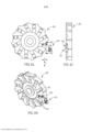
[007] Um desses conjuntos de ferramenta de corte da técnica anterior 10 é descrito em EP 2822720B1, atribuído ao presente requerente, e é exemplificado esquematicamente na Figura 1. Este conjunto de ferramenta de corte 10 mostra uma orientação comumente usada de uma lâmina de sangramento 12, inserto de corte 14 e suporte de ferramenta 16, configurados para particionar uma peça de trabalho 18. Esta publicação também descreve o uso de líquido de arrefecimento de alta pressão através de, isto é interno a, o suporte de ferramenta e a lâmina de sangramento para resfriar o inserto.[007] One such prior art
[008] Outro conjunto de ferramenta de corte da técnica anterior 20 é divulgado na Sandvik Group Magazine intitulada "Meet Sandvik # 2-2017" (página 7), a seguir denominada "a revista". Uma lâmina de sangramento 22 de acordo com esta divulgação foi reproduzida esquematicamente na Figura 2 e mostrada mantida por um suporte de ferramenta 24 idêntico ao mostrado na Figura 1 (note que na revista um suporte de ferramenta diferente é divulgado). Deve ser entendido que esta reprodução é apenas para auxiliar o entendimento básico, e os comentários geralmente feitos daqui em diante direcionados à “Figura 2” devem ser direcionados à divulgação na revista, se houver alguma imprecisão. Além disso, uma peça de trabalho 25 foi esquematicamente adicionada para compreensão. A lâmina de sangramento 22 na revista difere principalmente da lâmina de sangramento 12 na Figura 1, em que o assento de inserto 26 da lâmina de sangramento é girado 90° para usar o movimento de alimentação no eixo y. Em outras palavras, a superfície de saída 50 da lâmina de sangramento 22 na Figura 2 é basicamente perpendicular a um alongamento da lâmina de sangramento 22, enquanto a superfície de saída 48 da lâmina de sangramento 12 é basicamente paralela a um alongamento da lâmina de sangramento 12.[008] Another set of prior
[009] Referida orientação de cavidade é alegada proporcionar uma melhor estabilidade e menos vibração dado que a força de corte é mais dirigida na direção da extensão longitudinal da lâmina de sangramento e, assim, permite taxas de alimentação significativamente mais elevadas. A lâmina de sangramento 22 também mostra uma lâmina de sangramento configurada para refrigerante através dela, como mostrado pelas saídas de refrigerante (cujas posições básicas são esquematicamente designadas 28 e 30) visíveis adjacentes a um inserto de corte 32 e um dispositivo de vedação 34 montado na lâmina 22.[009] Said cavity orientation is claimed to provide better stability and less vibration since the cutting force is directed more in the direction of the longitudinal extension of the bleed blade and thus allows significantly higher feed rates. The
[010] É um objeto da presente invenção fornecer uma lâmina de sangramento nova e aprimorada, e suporte de ferramenta, e conjunto de corte de ferramenta.[010] It is an object of the present invention to provide a new and improved bleed blade, and tool holder, and tool cutting assembly.
[011] De acordo com um primeiro aspecto da presente invenção, é fornecida uma lâmina de sangramento alongada tendo uma direção de alongamento básica e compreendendo: primeira e segunda superfícies laterais opostas estendendo entre a primeira e segunda bordas longitudinais e também estendendo entre a primeira e segunda bordas terminais opostas que são mais curtas que e estendem transversais à primeira e segunda bordas longitudinais; e um assento de inserto associado à primeira borda longitudinal e à primeira borda terminal; o assento de inserto compreendendo a primeira e segunda garras de inserto que formam uma lacuna de recepção de inserto (também referida como "lacuna" daqui em diante) em um local em que se opõem uma à outra, a lacuna de recepção de inserto que se abre em uma direção em direção à primeira borda terminal.[011] According to a first aspect of the present invention, there is provided an elongated bleed blade having a basic direction of elongation and comprising: first and second opposing side surfaces extending between first and second longitudinal edges and also extending between first and second longitudinal edges second opposite terminal edges that are shorter than and extend transverse to the first and second longitudinal edges; and an insert seat associated with the first longitudinal edge and the first end edge; the insert seat comprising first and second insert jaws forming an insert receiving gap (also referred to as a "gap" hereinafter) at a location where they oppose each other, the insert receiving gap opens in a direction towards the first terminal edge.
[012] De acordo com um segundo aspecto da presente invenção, é fornecida uma lâmina de sangramento alongada tendo uma direção de alongamento básica e compreendendo: primeira e segunda superfícies laterais opostas estendendo entre a primeira e segunda bordas longitudinais e também estendendo entre a primeira e segunda bordas terminais opostas que são mais curtas que e estendendo transversais em relação à primeira e segunda bordas longitudinais; e um assento de inserto associado à primeira borda longitudinal e à primeira borda terminal; o assento de inserto sendo configurado com uma superfície de encosto de assento inferior formada por uma primeira extremidade de borda longitudinal da primeira borda longitudinal e uma superfície de encosto de assento traseira formada por uma primeira extremidade de borda terminal da primeira borda terminal; em que a superfície de encosto de assento inferior e a superfície de encosto de assento traseira estendem não paralelas uma à outra.[012] According to a second aspect of the present invention, there is provided an elongated bleed blade having a basic direction of elongation and comprising: first and second opposing side surfaces extending between first and second longitudinal edges and also extending between first and second longitudinal edges second opposing terminal edges that are shorter than and extending transverse to the first and second longitudinal edges; and an insert seat associated with the first longitudinal edge and the first end edge; the insert seat being configured with a lower seat back surface formed by a first longitudinal edge end of the first longitudinal edge and a rear seat back surface formed by a first terminal edge end of the first terminal edge; wherein the lower seat back surface and the rear seat back surface extend non-parallel to each other.
[013] Será entendido que o primeiro e o segundo aspectos ambos definem um conceito semelhante de maneiras alternativas, a saber, uma configuração de assento de inserto, para fornecer as vantagens sobre ambas as duas lâminas de sangramento da técnica anterior nas Figuras 1 e 2.[013] It will be understood that the first and second aspects both define a similar concept in alternative ways, namely an insert seat configuration, to provide the advantages over both of the two prior art bleed blades in Figures 1 and 2 .
[014] Para elaborar, o assento de inserto na Figura 1 fornece uma melhor evacuação de cavacos do que a mostrada na Figura 2, porque não há garra de inserto 36 (Figura 2) localizada acima da superfície de saída 48 do inserto de corte 14, permitindo mais espaço para que os cavacos fluam sem impedimentos. No entanto, a estabilidade adicional teórica da lâmina de sangramento 22 na Figura 2 não é fornecida. Por outro lado, o assento de inserto 26 na Figura 2 tem uma saída de refrigerante 28 extremamente próxima ao inserto de corte (ou seja, qual proximidade é devido à existência da garra de inserto 36 que compreende a saída de refrigerante 28) e a lâmina de sangramento 22 do mesmo tem a suposta estabilidade adicional, mas não possui a capacidade de evacuação de cavacos adicional da configuração na Figura 1.[014] To elaborate, the insert seat in Figure 1 provides better chip evacuation than that shown in Figure 2, because there is no insert claw 36 (Figure 2) located above the
[015] Ainda outra vantagem independente que foi encontrada, é que para aplicações de alta alimentação (por exemplo, maior que 0,20 mm/rev), o uso de uma garra elástica é mais desvantajoso do que em aplicações de alimentação normais (por exemplo, menor ou igual a 0,20 mm/rev), uma vez que perde rapidamente a elasticidade devido ao aumento das forças. Será entendido que um assento de inserto para alimentação alta desprovido de uma garra elástica é um benefício independente em si.[015] Yet another independent advantage that has been found is that for high feed applications (e.g. greater than 0.20 mm/rev), the use of an elastic grip is more disadvantageous than in normal feed applications (e.g. less than or equal to 0.20 mm/rev), as it quickly loses elasticity due to increased forces. It will be understood that a high feed insert seat devoid of an elastic gripper is an independent benefit in itself.
[016] Por conseguinte, um terceiro aspecto é uma lâmina de sangramento para aplicações de alta alimentação (por exemplo, igual ou superior a 0,20 mm/rev) ou profundidade de corte relativamente longa (por exemplo > 50 mm), a lâmina de sangramento compreendendo um assento de inserto configurado com uma superfície de encosto de assento inferior e uma superfície de encosto de assento traseira; em que a superfície de encosto de assento inferior e a superfície de encosto de assento traseira estendem não paralelas uma à outra. Preferencialmente, uma superfície de encosto de assento inferior pode se estender basicamente perpendicular à superfície de encosto de assento traseira. Mais preferencialmente, a superfície de encosto de assento traseira pode se estender basicamente em ângulo reto com a superfície de encosto de assento inferior. Para esclarecer, a referida lâmina de sangramento é desprovida de uma garra estendendo acima do assento de inserto (isto é, estendendo oposta à superfície de encosto de assento inferior ou mesmo apenas sobre uma lacuna formada entre a superfície de encosto de assento inferior e a superfície de encosto de assento traseira).[016] Therefore, a third aspect is a bleed blade for high feed applications (e.g. equal to or greater than 0.20 mm/rev) or relatively long depth of cut (e.g. > 50 mm), the blade a bleeder comprising an insert seat configured with a lower seat back surface and a rear seat back surface; wherein the lower seat back surface and the rear seat back surface extend non-parallel to each other. Preferably, a lower seat back surface may extend substantially perpendicular to the rear seat back surface. More preferably, the rear seat back surface may extend at basically right angles to the lower seat back surface. To clarify, said bleed blade is devoid of a claw extending above the insert seat (i.e., extending opposite the lower seat back surface or even just over a gap formed between the lower seat back surface and the lower seat back surface). rear seat back).
[017] Será entendido que a referida lâmina de sangramento com assento de inserto desprovida da referida garra estendendo sobre a lacuna ou a superfície de encosto de assento inferior é um recurso independentemente vantajoso que pode ser aplicável a qualquer um dos outros aspectos. No entanto, também será entendido que os outros aspectos não se limitam a este tipo específico de assento de inserto.[017] It will be understood that said insert seat bleed blade devoid of said gripper extending over the gap or bottom seat abutment surface is an independently advantageous feature that may be applicable to any of the other aspects. However, it will also be understood that the other aspects are not limited to this specific type of seat insert.
[018] Mesmo que a presente invenção, como mostrado na Figura 3, não tenha o benefício vantajoso de uma saída de refrigerante tão próxima a uma borda de corte no lado da superfície de saída, como a mostrada na Figura 2, acredita-se que a capacidade de evacuação de cavacos vantajosa supera esse prejuízo, especialmente para a lâmina de sangramento que pode ser usada para taxas de alimentação comparativamente altas e para os cavacos associados.[018] Even though the present invention, as shown in Figure 3, does not have the advantageous benefit of a coolant outlet so close to a cutting edge on the side of the outlet surface, as shown in Figure 2, it is believed that the advantageous chip evacuation capability outweighs this detriment, especially for the bleed blade which can be used for comparatively high feed rates and the associated chips.
[019] De acordo com qualquer um dos aspectos acima, preferencialmente, uma superfície de encosto de assento inferior pode se estender basicamente perpendicular à direção de alongamento e uma superfície de encosto de assento traseira pode se estender basicamente paralela à direção de alongamento. Mais preferencialmente, a superfície de encosto de assento traseira pode se estender basicamente em ângulo reto com a superfície de encosto de assento inferior e pode se estender basicamente paralela à direção de alongamento.[019] According to any of the above aspects, preferably, a lower seat back surface can extend basically perpendicular to the elongation direction and a rear seat back surface can extend basically parallel to the elongation direction. More preferably, the rear seat back surface can extend basically at right angles to the lower seat back surface and can extend basically parallel to the direction of elongation.
[020] De acordo com qualquer um dos aspectos acima, pode ser fornecido um assento de inserto adicional associado à segunda borda longitudinal e à primeira borda terminal. Preferencialmente, o assento de inserto adicional tem uma construção de assento de inserto correspondente.[020] According to any of the above aspects, an additional insert seat associated with the second longitudinal edge and the first terminal edge can be provided. Preferably, the additional seat insert has a corresponding seat insert construction.
[021] Deve ser notado que, na configuração da Figura 2, a conexão flexível 38 da primeira e segunda garras de inserto 36, 40 está localizada perto de um canto oposto 42 associado à segunda borda longitudinal 44 e à primeira borda terminal 46. Será entendido que essa configuração permite apenas um único assento de inserto associado à primeira borda terminal 46 (observando que a primeira borda é a borda mais curta da lâmina de sangramento e, portanto, está relativamente próxima). Em contraste, referindo-se à Figura 3, uma vez que a conexão flexível comparativa nas garras de inserto não está localizada próxima a um canto adjacente da primeira borda, um segundo inserto pode ser fornecido que está associado à primeira borda. Será entendido que, ao fornecer assentos de inserto adicionais em uma única lâmina de sangramento, a vida útil da ferramenta da lâmina de sangramento aumenta significativamente. Este é um benefício independente da presente invenção, além do fluxo aprimorado de cavacos discutido acima.[021] It should be noted that, in the configuration of Figure 2, the
[022] De acordo com qualquer um dos aspectos acima, pode ser fornecido um assento (s) de inserto adicional associado com a segunda borda terminal.[022] According to any of the above aspects, an additional insert seat(s) associated with the second end edge can be provided.
[023] Como é entendido a partir da lâmina de sangramento da técnica anterior na Figura 2, o projeto não indexável provavelmente derivaria da conexão flexível 38 do assento de inserto 26 localizada na borda curta da lâmina de sangramento. Observando que, diferentemente da Figura 1, as forças de corte na Figura 2 provavelmente exigiriam um batente posicionado na parte traseira 47 da lâmina, era claramente preferido não fornecer uma conexão flexível e danificável para encosto contra um batente.[023] As understood from the prior art bleed blade in Figure 2, the non-indexable design would likely derive from the
[024] No entanto, para os aspectos acima, que não compreendem uma conexão flexível em tal local, existe uma vantagem adicional de que pelo menos um assento de inserto possa ser localizado em ambas da primeira e segunda bordas terminais.[024] However, for the above aspects, which do not comprise a flexible connection in such a location, there is an additional advantage that at least one insert seat can be located on both the first and second end edges.
[025] De acordo com qualquer um dos aspectos acima, independentemente do tipo de assento de inserto, uma borda longitudinal associada a um assento de inserto pode se estender em uma direção oblíqua, de modo que se estenda por baixo do assento de inserto. Em outras palavras, uma direção de alongamento de uma lâmina de sangramento pode ser não ortogonal a uma superfície de saída de um inserto de corte.[025] According to any of the above aspects, regardless of the type of insert seat, a longitudinal edge associated with an insert seat may extend in an oblique direction, so that it extends underneath the insert seat. In other words, a direction of elongation of a bleed blade can be non-orthogonal to a rake surface of a cutting insert.
[026] Será entendido que em ambas as lâminas da técnica anterior nas Figuras 1 e 2, a borda longitudinal 44, 45, não se estende em uma direção de alongamento oblíqua da lâmina de sangramento, de modo que ela se estenda por baixo do assento de inserto. Da mesma forma, as superfícies de saída 48, 50 em ambas as divulgações são basicamente paralelas ou basicamente perpendiculares à direção de alongamento.[026] It will be understood that in both of the prior art blades in Figures 1 and 2, the
[027] Ao fornecer esse recurso (daqui em diante a "construção de lâmina de sangramento oblíqua"), a presente invenção fornece, em teoria, uma lâmina de sangramento mais estável do que a conhecida na técnica anterior, uma vez que a força de corte aplicada a uma lâmina de sangramento é mais direcionada ao longo do comprimento da lâmina. Enquanto apreciamos que variáveis diferentes, como o diâmetro da peça de trabalho, variam a direção de força de corte, o ângulo oblíquo mais preferido θ preenche a condição: 60° > θ > 0°, mais preferencialmente 50° > θ > 10° e mais preferencialmente 40° > θ > 20°. Além disso, acredita-se que valores são mais benéficos à medida que tendem a 30°. O ângulo oblíquo θ sendo mensurável entre uma linha perpendicular ao eixo de haste de ferramenta e a borda longitudinal estendendo obliquamente mais à frente.[027] By providing this feature (hereinafter the "oblique bleed blade construction"), the present invention provides, in theory, a more stable bleed blade than known in the prior art, since the force of cut applied to a bleeding blade is more directed along the length of the blade. While we appreciate that different variables such as workpiece diameter vary the cutting force direction, the most preferred oblique angle θ fulfills the condition: 60° > θ > 0°, most preferably 50° > θ > 10° and more preferably 40° > θ > 20°. Furthermore, it is believed that values are more beneficial as they tend towards 30°. The oblique angle θ being measurable between a line perpendicular to the tool shank axis and the longitudinal edge extending obliquely further forward.
[028] Mesmo que essa construção oblíqua da lâmina de sangramento possa ser vantajosa em relação à direção de força de corte, a remoção do material diretamente sob um inserto de corte, por exemplo, no lado de borda longitudinal de um assento de inserto, enfraquece a resistência de construção do assento de inserto.[028] Even though this oblique construction of the bleed blade can be advantageous in relation to the direction of cutting force, removing material directly under a cutting insert, for example, on the longitudinal edge side of an insert seat, weakens the strength of insert seat construction.
[029] Por conseguinte, além de proporcionar a construção da lâmina de sangramento oblíqua, o referido enfraquecimento pode ser combatido fornecendo uma sub-borda ortogonal adjacente ao assento de inserto. Para elaborar, uma porção de sub-borda ortogonal de uma borda longitudinal associada a um assento de inserto pode se estender em uma direção não oblíqua (por exemplo, não se estender obliquamente sob o assento de inserto ou, de forma diferente, estender ortogonal a uma superfície de saída), e uma sub-borda oblíqua conectada pode se estender a partir da sub-borda ortogonal em direção a uma borda terminal oposta.[029] Therefore, in addition to providing the construction of the oblique bleed blade, said weakening can be countered by providing an orthogonal sub-edge adjacent to the insert seat. To elaborate, an orthogonal sub-edge portion of a longitudinal edge associated with an insert seat may extend in a non-oblique direction (e.g., not extend obliquely under the insert seat or, differently, extend orthogonal to an output surface), and a connected oblique sub-edge may extend from the orthogonal sub-edge towards an opposite terminal edge.
[030] Essa porção de sub-borda ortogonal pode fornecer dois benefícios independentes. Um primeiro benefício do reforço da garra de inserto associada à borda longitudinal (ou seja, permitindo que ela seja mais espessa e/ou se estenda diretamente abaixo do inserto de corte e forneça mais suporte, e um segundo benefício de que o assento de inserto é movido para mais perto do meio da primeira ou segunda borda terminal, direcionando assim a força de corte ainda mais centralmente ao longo da direção de alongamento da lâmina de sangramento.[030] This orthogonal sub-edge portion can provide two independent benefits. A first benefit of the reinforcement of the insert grip associated with the longitudinal edge (i.e. allowing it to be thicker and/or to extend directly below the cutting insert and provide more support, and a second benefit that the insert seat is moved closer to the middle of the first or second terminal edge, thus directing the cutting force even more centrally along the direction of elongation of the bleed blade.
[031] Por conseguinte, em um quarto aspecto da presente invenção, é fornecida uma lâmina de sangramento alongada tendo uma direção de alongamento básica e compreendendo: primeira e segunda superfícies laterais opostas estendendo entre a primeira e segunda bordas longitudinais e também estendendo entre a primeira e segunda bordas terminais opostas que são mais curtas que e estendem transversais à primeira e segunda bordas longitudinais; e um assento de inserto associado à primeira borda longitudinal e à primeira borda terminal; o assento de inserto sendo rebaixado em direção à segunda borda longitudinal.[031] Therefore, in a fourth aspect of the present invention, there is provided an elongated bleed blade having a basic direction of elongation and comprising: first and second opposite side surfaces extending between the first and second longitudinal edges and also extending between the first and second opposite terminal edges that are shorter than and extend transverse to the first and second longitudinal edges; and an insert seat associated with the first longitudinal edge and the first end edge; the insert seat being recessed towards the second longitudinal edge.
[032] Em outras palavras, o termo "rebaixado em direção à segunda borda longitudinal" poderia ser definido alternadamente como distanciado de uma linha de extensão imaginária da primeira borda longitudinal em uma direção em direção à segunda borda longitudinal.[032] In other words, the term "recessed towards the second longitudinal edge" could alternately be defined as being distanced from an imaginary extension line of the first longitudinal edge in a direction towards the second longitudinal edge.
[033] Independentemente da terminologia utilizada, será entendido que esse aspecto fornece a centralização da força de corte como descrito acima. Também deve ser entendido que qualquer um dos recursos mencionados acima com relação ao primeiro, segundo e terceiro aspectos também seja aplicável a esse aspecto que define um local preferido de um assento de inserto e não uma construção de assento de inserto específica.[033] Regardless of the terminology used, it will be understood that this aspect provides the centering of the cutting force as described above. It should also be understood that any of the features mentioned above with respect to the first, second and third aspects are also applicable to that aspect which defines a preferred location of an insert seat and not a specific insert seat construction.
[034] De acordo com um quinto aspecto da presente invenção, proporciona-se uma lâmina de sangramento alongada tendo uma direção de alongamento básica e compreendendo: primeira e segunda superfícies laterais opostas estendendo entre primeira e segunda bordas longitudinais e também estendendo entre primeira e segunda bordas terminais opostas que são mais curtas que a primeira e segunda bordas longitudinais; a primeira e segunda bordas longitudinais estendendo ao longo da direção de alongamento básica; a lâmina de sangramento compreendendo ainda um assento de inserto que se abre para ou próximo à primeira borda terminal; o assento de inserto compreendendo uma superfície de encosto de assento inferior e pelo menos uma superfície de encosto adicional; e em que a primeira borda longitudinal compreende uma porção próxima que está próxima e estende por baixo da superfície de encosto de assento inferior.[034] According to a fifth aspect of the present invention, there is provided an elongated bleed blade having a basic direction of elongation and comprising: first and second opposing side surfaces extending between first and second longitudinal edges and also extending between first and second opposing terminal edges that are shorter than the first and second longitudinal edges; the first and second longitudinal edges extending along the basic elongation direction; the bleed blade further comprising an insert seat opening to or near the first terminal edge; the insert seat comprising a lower seat abutment surface and at least one additional abutment surface; and wherein the first longitudinal edge comprises a proximate portion which is proximate and extends below the lower seat back surface.
[035] Mais precisamente, o assento de inserto pode abrir para uma da (a) primeira borda terminal, (b) tanto a primeira borda terminal quanto a primeira borda longitudinal, ou (c) a primeira borda longitudinal em uma porção adjacente à primeira borda terminal.[035] More precisely, the insert seat can open to one of (a) the first terminal edge, (b) both the first terminal edge and the first longitudinal edge, or (c) the first longitudinal edge in a portion adjacent to the first terminal edge.
[036] Preferencialmente, a porção próxima se estende por baixo de todo o assento de inserto.[036] Preferably, the proximal portion extends underneath the entire insert seat.
[037] Preferencialmente, a porção próxima se estende tanto na direção traseira e na direção descendente (DR, DD).[037] Preferably, the proximate portion extends both in the rear direction and in the downward direction (DR, DD).
[038] Preferencialmente, um ângulo de lâmina oblíquo θ1, mensurável entre a direção descendente DD e a porção próxima preenche a condição: 60° > θ1 > 0°, mais preferencialmente 50° > θ1 > 10° e, mais preferencialmente, 40° > θ1 > 20°. Além disso, acredita-se que os valores do ângulo de lâmina oblíquo θ1 sejam mais benéficos, pois tendem a 30°.[038] Preferably, an oblique blade angle θ1, measurable between the downward direction DD and the proximal portion fulfills the condition: 60° > θ1 > 0°, more preferably 50° > θ1 > 10°, and most preferably 40° > θ1 > 20°. Furthermore, it is believed that the values of the oblique blade angle θ1 are more beneficial, as they tend towards 30°.
[039] A pelo menos uma superfície de encosto adicional acima mencionada pode ou ser uma superfície de encosto de uma garra superior (semelhante ao tipo de cavidade mostrado na Figura 2, a garra superior sendo designada como "36" e, consequentemente, o pelo menos um encosto adicional opõe-se à superfície de encosto de assento inferior) ou pode ser uma superfície de encosto de assento traseira (semelhante ao tipo de cavidade mostrada na Figura 5B, designado como "134B" e, portanto, pelo menos um encosto adicional é basicamente perpendicular à superfície de encosto de assento inferior). A orientação precisa da superfície de encosto adicional não é importante, pelo contrário, será entendido que normalmente um inserto precisa ser fixado por mais de uma superfície de encosto e a localização da superfície de encosto de assento inferior está sendo usada para descrever a orientação relativa da porção próxima. Também deve ser entendido que a superfície de encosto de assento inferior pode, e geralmente será, diferente de uma superfície plana, mas que basicamente se encontra em um plano de assento PS (consulte a Figura 16B). O plano de assento é basicamente perpendicular à primeira e segunda superfícies laterais e paralelo às direções para frente e para trás (DF, DR).[039] The at least one additional abutment surface mentioned above can either be an abutment surface of an upper claw (similar to the type of cavity shown in Figure 2, the upper claw being designated as "36" and, consequently, the hair at least one additional backrest opposes the lower seatback surface) or may be a rear seatback surface (similar to the type of cavity shown in Figure 5B, designated as "134B" and therefore at least one additional backrest is basically perpendicular to the lower seat back surface). The precise orientation of the additional backrest surface is not important, rather it will be understood that normally an insert needs to be attached by more than one backrest surface and the location of the lower seat back surface is being used to describe the relative orientation of the next portion. It should also be understood that the lower seat back surface can, and usually will, be different from a flat surface, but that it basically lies on a PS seat plane (see Figure 16B). The seat plane is basically perpendicular to the first and second side surfaces and parallel to the forward and backward directions (DF, DR).
[040] A lâmina de sangramento alongada pode ter uma forma linear ou uma forma não linear. Por exemplo, a lâmina de sangramento alongada pode ser dobrada ou curva. Nas modalidades onde a lâmina de sangramento compreende uma dobra, a dobra pode preferencialmente estar localizada aproximadamente no centro do comprimento da lâmina. Preferencialmente, a dobra pode estar exatamente no meio do comprimento da lâmina, permitindo que a lâmina seja igualmente indexável em torno do meio da mesma.[040] The elongated bleed blade can have a linear shape or a non-linear shape. For example, the elongated bleed blade can be bent or curved. In embodiments where the bleed blade comprises a fold, the fold may preferably be located approximately in the center of the length of the blade. Preferably, the fold can be exactly in the middle of the length of the blade, allowing the blade to be equally indexable about the middle of the blade.
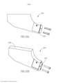
[041] Tal lâmina pode ter, por exemplo, em uma posição, uma porção de aperto estendendo verticalmente e uma porção de corte estendendo obliquamente (essas porções podem alternar funções quando indexadas, se indexáveis). Por conseguinte, por exemplo, a lâmina pode ser montada em um suporte de ferramenta relativamente compacto 64, como mostrado na Figura 3, mas ainda tem a orientação oblíqua vantajosa fornecida nos conjuntos de corte mostrados, por exemplo, nas Figuras 6 e 7A. Além disso, essa lâmina pode ser montada em um suporte de ferramenta padrão 16 ou 24 (por exemplo, mostrado nas Figuras 1 e 2) projetado para uma lâmina não oblíqua.[041] Such a blade may have, for example, in one position, a gripping portion extending vertically and a cutting portion extending obliquely (these portions may alternate functions when indexed, if indexable). Therefore, for example, the blade can be mounted in a relatively
[042] Será entendido que essa lâmina de sangramento pode até ser montada em diferentes comprimentos de suspensão, se desejado. Isso além de uma aplicação de força vantajosa.[042] It will be understood that this bleed blade can even be mounted on different suspension lengths if desired. This is in addition to an advantageous application of force.
[043] Testes iniciais foram feitos com uma lâmina linear tendo um ângulo oblíquo de 15° (Figura 7A) e -15° (não mostrado) bem como 0° (Figura 3) com a estabilidade sendo excelente em todos os ângulos. Em testes recentes, uma lâmina linear com um ângulo de orientação oblíquo de 30° (em uma configuração semelhante à lâmina mostrada na Figura 7A) apresentou resultados superiores (realizando aproximadamente o dobro do número de fendas para as modalidades mencionadas acima). Uma lâmina não linear do tipo mostrado nas Figuras 16A-16E e tendo um ângulo de orientação oblíquo de 30° deve ter benefícios semelhantes aos da lâmina linear testada.[043] Initial tests were made with a linear blade having an oblique angle of 15° (Figure 7A) and -15° (not shown) as well as 0° (Figure 3) with stability being excellent at all angles. In recent tests, a linear blade with an oblique orientation angle of 30° (in a configuration similar to the blade shown in Figure 7A) showed superior results (performing approximately twice the number of slits for the modalities mentioned above). A non-linear blade of the type shown in Figures 16A-16E and having an oblique orientation angle of 30° should have similar benefits to the linear blade tested.
[044] De acordo com sexto aspecto da presente invenção, proporciona-se uma lâmina de sangramento alongada tendo uma direção de alongamento básica e compreendendo: primeira e segunda superfícies laterais opostas estendendo entre a primeira e segunda bordas longitudinais e também estendendo entre a primeira e segunda bordas terminais opostas que são mais curtas que e estendem transversalmente em relação a primeira e segunda bordas longitudinais; e um assento de inserto associado à primeira borda longitudinal e à primeira borda terminal; a primeira borda terminal compreendendo ainda uma porção saliente que se projeta adicionalmente na direção de alongamento básica do que o assento de inserto; a porção saliente compreendendo uma abertura de saída de lâmina direcionada na direção do assento de inserto.[044] According to the sixth aspect of the present invention, there is provided an elongated bleed blade having a basic direction of elongation and comprising: first and second opposite side surfaces extending between the first and second longitudinal edges and also extending between the first and second second opposing terminal edges that are shorter than and extend transversely of the first and second longitudinal edges; and an insert seat associated with the first longitudinal edge and the first end edge; the first terminal edge further comprising a projecting portion further projecting in the basic elongation direction than the insert seat; the projecting portion comprising a blade exit opening directed towards the insert seat.
[045] Embora a provisão da porção saliente diminua o espaço disponível para evacuação de cavacos discutido acima, acredita-se que a provisão vantajosa de refrigerante supere esse prejuízo em pelo menos alguns casos.[045] Although the provision of the protruding portion decreases the space available for chip evacuation discussed above, it is believed that the advantageous provision of coolant overcomes this loss in at least some cases.
[046] De acordo com um sétimo aspecto da presente invenção, é fornecida uma lâmina de sangramento e um dispositivo de vedação para a lâmina de sangramento, a lâmina de sangramento compreendendo: primeira e segunda superfícies laterais opostas estendendo entre e bordas periféricas; e um assento de inserto; a lâmina de sangramento compreendendo ainda um arranjo de refrigerante interno compreendendo uma abertura de entrada de lâmina para a primeira e segunda superfícies laterais, uma abertura de saída de lâmina que se abre em ou em direção ao assento de inserto, e uma via de passagem de lâmina estendendo a partir da abertura de entrada de lâmina para a abertura de saída de lâmina; o dispositivo de vedação compreendendo uma porção de vedação configurada para vedar a abertura de entrada de lâmina na segunda superfície lateral e uma porção de haste pelo menos parcialmente roscada que é maior que uma espessura de lâmina medida a partir da primeira à segunda superfície lateral; a lâmina de sangramento sendo desprovida de um orifício rosqueado configurado para recebimento da porção de haste roscada.[046] According to a seventh aspect of the present invention, there is provided a bleed blade and a sealing device for the bleed blade, the bleed blade comprising: first and second opposing side surfaces extending between and peripheral edges; and an insert seat; the bleed blade further comprising an internal coolant arrangement comprising a blade entry opening for the first and second side surfaces, a blade exit opening opening into or towards the insert seat, and a blade passageway blade extending from the blade entry opening to the blade exit opening; the sealing device comprising a sealing portion configured to seal the blade entry opening in the second side surface and an at least partially threaded shank portion which is greater than a blade thickness measured from the first to the second side surface; the bleed blade being devoid of a threaded hole configured to receive the threaded rod portion.
[047] Será entendido que a porção de haste é configurada para se estender através da lâmina e conectar-se de maneira roscada a um orifício roscado de um suporte de ferramenta que segura a lâmina de sangramento. Como a lâmina de sangramento também pode ser fabricada sem um orifício roscado para fixação do dispositivo de vedação, a fabricação da lâmina é simplificada (por exemplo, fornecendo um orifício sem rosca simples); a lâmina de sangramento pode potencialmente ser mais fina que uma lâmina comparativa com um orifício roscado (uma vez que normalmente são necessárias pelo menos três rotações de rosca para uma conexão segura que define uma espessura de lâmina mínima).[047] It will be understood that the rod portion is configured to extend through the blade and threadably connect to a threaded hole of a tool holder that holds the bleed blade. As the bleed blade can also be manufactured without a threaded hole for attaching the sealing device, the manufacture of the blade is simplified (for example, providing a simple threadless hole); the bleed blade can potentially be thinner than a comparative blade with a threaded hole (since at least three thread rotations are typically required for a secure connection which defines a minimum blade thickness).
[048] Outra vantagem pode ser que, teoricamente, é possível fixar a abertura de entrada de lâmina com engate direto no suporte de ferramenta, possibilitando assim a transferência de refrigerante de alta pressão sem a necessidade de um anel de vedação e construção associada entre a lâmina de sangramento e o suporte de ferramenta.[048] Another advantage may be that, theoretically, it is possible to fix the blade inlet opening with direct engagement in the tool holder, thus enabling the transfer of high pressure coolant without the need for a sealing ring and associated construction between the bleed blade and tool holder.
[049] Por conseguinte, acredita-se teoricamente possível proporcionar uma lâmina de sangramento com uma espessura de 2,2 mm ou menos, preferencialmente 2,0 mm ou menos e mais preferencialmente entre 1,7 mm a 1,9 mm, inclusive. A referida espessura refere-se à espessura de toda a lâmina (será entendido que existem lâminas de sangramento que têm uma espessura muito pequena perto de um assento de inserto e um aumento ampliado espaçado do assento de inserto).[049] Therefore, it is believed theoretically possible to provide a bleed sheet with a thickness of 2.2 mm or less, preferably 2.0 mm or less, and more preferably between 1.7 mm to 1.9 mm, inclusive. Said thickness refers to the thickness of the entire blade (it will be understood that there are bleed blades which have a very small thickness close to an insert seat and an enlarged increase spaced from the insert seat).
[050] O presente aspecto pode ser aplicado a lâminas de sangramento alongadas, particularmente tendo uma direção de alongamento básica, primeira e segunda bordas longitudinais e primeira e segunda bordas terminais opostas que são mais curtas e estendendo transversalmente à primeira e segunda bordas longitudinais, um assento de inserto sendo associado à primeira borda longitudinal e à primeira borda terminal.[050] The present aspect may be applied to elongated bleed blades, particularly having a basic elongation direction, first and second longitudinal edges and opposing first and second terminal edges that are shorter and extending transversely to the first and second longitudinal edges, a insert seat being associated with the first longitudinal edge and the first terminal edge.
[051] Além disso, diferentemente de alguns dos outros aspectos do presente pedido, a vantagem de uma lâmina de sangramento desprovida de orifícios roscados entre a primeira e segunda superfícies laterais opostas é vantajosa mesmo para as lâminas de sangramento que não são alongadas (por exemplo, lâminas de sangramento do tipo divulgado no documento WO2018/047162, lá denominadas "adaptadores", sendo o referido pedido de patente atribuído ao presente requerente e cujo conteúdo é aqui incorporado por referência).[051] Furthermore, unlike some of the other aspects of the present application, the advantage of a bleed blade devoid of threaded holes between the first and second opposing side surfaces is advantageous even for bleed blades that are not elongated (for example , bleeding blades of the type disclosed in WO2018/047162, there called "adapters", said patent application being assigned to the present applicant and whose content is incorporated herein by reference).
[052] Será apreciado que o benefício de uma lâmina de sangramento desprovida de um orifício roscado, permitindo que uma espessura muito pequena da lâmina, não é relacionado ao formato da lâmina de sangramento.[052] It will be appreciated that the benefit of a bleed blade devoid of a threaded hole, allowing for a very small blade thickness, is unrelated to the shape of the bleed blade.
[053] Em resumo, os recursos do sétimo aspecto também podem ser aplicados a uma lâmina não alongada, por exemplo, uma lâmina de sangramento não alongada com um ou mais assentos de inserto.[053] In summary, the features of the seventh aspect can also be applied to a non-elongated blade, for example, a non-elongated bleed blade with one or more insert seats.
[054] Deve ser notado que o primeiro, segundo, terceiro e quarto aspectos são dirigidos para construção associada com o assento de inserto, o quinto aspecto com a forma de lâmina, e o sexto e sétimo aspectos são dirigidos para os recursos de construção de refrigerante. Por conseguinte, deve ser entendido que tanto o sexto e sétimo podem ser combinados com qualquer um dos aspectos não relacionados do primeiro a quinto aspectos para proporcionar uma lâmina de sangramento ainda mais vantajosa. Vai também ser entendido que uma lâmina de sangramento de acordo com qualquer dos primeiros quatro aspectos, pode ser desprovida de uma construção de refrigerante, se desejado.[054] It should be noted that the first, second, third and fourth aspects are directed towards construction associated with the insert seat, the fifth aspect towards the blade shape, and the sixth and seventh aspects are directed towards the construction features of refrigerator. Therefore, it should be understood that both the sixth and seventh can be combined with any of the unrelated aspects of the first through fifth aspects to provide an even more advantageous bleed blade. It will also be understood that a bleed blade according to any of the first four aspects can be devoid of a coolant construction, if desired.
[055] Adicionais ao que é indicado na discussão do aspecto de orifício roscado (sexto aspecto), uma lâmina de sangramento pode ser capaz de ser feita mais fina do que as lâminas comparativas conhecidas, devido à maior estabilidade fornecida pela orientação do inserto de corte dirigindo a força de corte longitudinalmente na lâmina.[055] In addition to what is indicated in the discussion of the threaded hole aspect (sixth aspect), a bleed blade may be able to be made thinner than known comparative blades, due to the greater stability provided by the orientation of the cutting insert directing the cutting force longitudinally on the blade.
[056] Por conseguinte, de acordo com qualquer um dos aspectos acima, uma lâmina de sangramento pode ter uma espessura de lâmina de 2,2 mm ou menos. A referida espessura de lâmina pode estar de acordo com os valores definidos acima.[056] Accordingly, in accordance with any of the above aspects, a bleed blade may have a blade thickness of 2.2 mm or less. Said blade thickness can be according to the values defined above.
[057] Como será discutido abaixo em relação ao suporte de ferramenta, um suporte de ferramenta preferido para qualquer um dos aspectos pode segurar uma lâmina de sangramento em uma única posição, ou seja, sem a possibilidade de alterar o comprimento da suspensão conforme exemplificado nas lâminas de sangramento da técnica anterior nas Figuras 1 e 2. Nas modalidades em que tal recurso é levado em consideração, de acordo com qualquer um dos aspectos acima, uma relação entre o comprimento de lâmina máximo LB e o comprimento de haste LS, sendo ambas medidas paralelamente a uma direção de alongamento, pode preencher a condição LS/LB <0,45, preferencialmente LS/LB <0,40 e mais preferencialmente LS/LB <0,35. O comprimento de haste LS é a menor distância mensurável a partir de uma segunda borda terminal a uma abertura de entrada de lâmina configurada para um assento de inserto localizado na primeira borda terminal.[057] As will be discussed below in relation to the tool holder, a preferred tool holder for any of the aspects can hold a bleed blade in a single position, that is, without the possibility of changing the length of the suspension as exemplified in the prior art bleeding blades in Figures 1 and 2. In embodiments where such a feature is taken into account, according to any of the above aspects, a ratio between the maximum blade length LB and the shank length LS, both being measured parallel to a direction of elongation, may fulfill the condition LS/LB <0.45, preferably LS/LB <0.40, and most preferably LS/LB <0.35. Shank length LS is the shortest measurable distance from a second end edge to a blade entry opening configured for an insert seat located on the first end edge.
[058] Deve ser entendido que, se o comprimento de lâmina máximo LB é teoricamente dividido em um comprimento de haste LS (para a montagem de um suporte de ferramenta) e o restante sendo um comprimento de suspensão LO, a combinação das construções de assento de inserto detalhadas acima e o conjunto de ferramenta de corte não sendo configurado para diferentes balanços (como será descrito abaixo) permite um comprimento de haste LS muito menor do que o usado anteriormente para lâminas de sangramento. Em teoria, o comprimento de haste LS pode mesmo ser tão curto como, aproximadamente, o mesmo comprimento que uma largura de lâmina WB.[058] It should be understood that if the maximum blade length LB is theoretically divided into a shank length LS (for mounting a toolholder) and the remainder being a suspension length LO, the combination of seat constructions of insert details detailed above and the cutting tool assembly not being configured for different overhangs (as will be described below) allows for a much shorter LS shank length than previously used for bleed blades. In theory, the LS shank length could even be as short as approximately the same length as a WB blade width.
[059] De acordo com um oitavo aspecto da presente invenção, é fornecido um suporte de ferramenta que compreende: uma haste de ferramenta tendo um eixo de haste definindo as direções para frente e para trás; e uma cabeça de ferramenta conectada à haste de ferramenta; a haste de ferramenta compreendendo superfícies de haste mais superior e mais inferior opostas que definem direções ascendente e descendente perpendicularmente ao eixo de haste, e compreendendo ainda primeira e segunda superfícies laterais de haste que definem primeira e segunda direções laterais perpendiculares ao eixo de haste e as direções ascendente e descendente; a cabeça de ferramenta estendendo nas direções para frente e descendente a partir de uma porção de haste frontal da haste de ferramenta e compreendendo uma cavidade de lâmina; a cavidade de lâmina compreendendo uma parede periférica formada por uma abertura de cavidade que se abre na direção ascendente.[059] According to an eighth aspect of the present invention, there is provided a tool holder comprising: a tool shank having a shank axis defining forward and backward directions; and a tool head connected to the tool shank; the tool shank comprising opposing uppermost and lowermost shank surfaces defining upward and downward directions perpendicular to the shank axis, and further comprising first and second shank side surfaces defining first and second lateral directions perpendicular to the shank axis and the ascending and descending directions; the tool head extending in forward and downward directions from a front shank portion of the tool shank and comprising a blade cavity; the blade cavity comprising a peripheral wall formed by a cavity opening opening in the upward direction.
[060] Sem estar vinculado aos detalhes no parágrafo anterior, o conceito geral da presente invenção é fornecer um suporte de ferramenta com uma orientação de haste tradicional (“horizontal”) semelhante à mostrada na Figura 1 e uma orientação de lâmina de sangramento não-tradicional (“vertical” ou “basicamente vertical”) semelhante à mostrada na Figura 2, permitindo assim que o suporte de ferramenta seja montado nas torres em máquinas tradicionais (normalmente sem capacidade de movimento vertical), proporcionando os benefícios de estabilidade do projeto na Figura 2. Os testes atuais mostraram que a presente invenção fornece estabilidade ainda melhor do que os projetos da técnica anterior. Como as máquinas tradicionais acima mencionadas carecem de capacidade de movimento vertical, de acordo com as modalidades preferenciais, o suporte de ferramenta é configurado para manter uma lâmina de sangramento em uma única posição (isto é, sem a possibilidade de alterar o comprimento da suspensão, essa capacidade está disponível nos suportes de ferramenta da técnica anterior nas figuras 1 e 2. Embora essa capacidade sempre tenha sido um dos principais recursos de um conjunto de ferramenta de corte com lâmina de sangramento, acredita-se que o compromisso de oferecer estabilidade superior supere essa desvantagem. Dito diferentemente, os aspectos de suporte de ferramenta e conjunto de ferramenta da presente invenção não estão restritos às construções de assento de inserto ou construções de refrigerante detalhadas nos aspectos anteriores, embora possam ser claramente vantajosos se usados em conjunto com elas.[060] Without being bound by the details in the previous paragraph, the general concept of the present invention is to provide a tool holder with a traditional ("horizontal") shank orientation similar to that shown in Figure 1 and a non-bleeding blade orientation. (“vertical” or “basically vertical”) similar to that shown in Figure 2, thus allowing the tool holder to be mounted on turrets on traditional machines (typically lacking vertical movement capability), providing the stability benefits of the design in Figure 2. Current testing has shown that the present invention provides even better stability than prior art designs. As the aforementioned traditional machines lack vertical movement capability, according to preferred embodiments, the tool holder is configured to hold a bleed blade in a single position (i.e., without the possibility of changing the suspension length, this capability is available on the prior art tool holders in figures 1 and 2. While this capability has always been one of the key features of a bleed blade cutting tool assembly, it is believed that the compromise to provide superior stability trumps this disadvantage Stated differently, the tool holder and tool assembly aspects of the present invention are not restricted to the insert seat constructions or coolant constructions detailed in the previous aspects, although they can clearly be advantageous if used in conjunction with them.
[061] Verificou-se também subsequentemente que, mesmo com máquinas com capacidade de movimento vertical, a presente invenção é vantajosa, uma vez que normalmente a capacidade de movimento vertical é configurada para usinagem mais leve ou mais fraca.[061] It was also subsequently found that, even with machines capable of vertical movement, the present invention is advantageous, since normally the capacity of vertical movement is configured for lighter or weaker machining.
[062] A cavidade de lâmina é configurada para segurar uma lâmina de sangramento. A cavidade de lâmina pode estar localizada no meio da cabeça de ferramenta (por exemplo, dentro de uma ranhura, não mostrada). Preferencialmente, no entanto, a cavidade de lâmina está localizada em uma superfície lateral de cabeça de ferramenta.[062] The blade cavity is configured to hold a bleed blade. The blade cavity may be located in the middle of the tool head (for example, inside a groove, not shown). Preferably, however, the blade cavity is located on a side surface of the tool head.
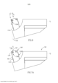
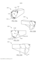
[063] A parede periférica pode compreender duas porções de parede lateral estendendo a partir da abertura de cavidade. As porções de parede lateral podem se estender na direção descendente. De acordo com uma modalidade preferida, as porções de parede lateral podem se estender nas direções descendente e para trás a partir da abertura de cavidade. Sem estar vinculado à teoria, acredita-se que a orientação descendente e para trás (por exemplo, Figura 6) é vantajosa em relação à única orientação descendente (90°) (Figura 3), em que vibração da lâmina de sangramento durante a usinagem é provável que resulte na parte desapertada da lâmina de sangramento se afastando da peça de trabalho devido às forças de corte e retornando em uma maneira pendular para impactá-la (será entendido que esse movimento é extremamente pequeno). Acredita-se ainda que a construção da lâmina de sangramento oblíqua seja superior, como explicado acima. No entanto, a Figura 3 constitui certamente uma modalidade possível da presente invenção. Deve ser notado que qualquer inclinação ascendente básica da lâmina de sangramento forneceria a vantagem básica da presente invenção, mesmo se a lâmina de sangramento fosse inclinada para trás (não mostrado), em vez de verticalmente na Figura 3 e para frente na Figura 6. No entanto, uma inclinação para trás exigiria que a cabeça de ferramenta tivesse uma construção mais volumosa na direção para frente do que uma inclinação vertical, e uma inclinação vertical mais que uma inclinação para frente. Como mostrado na Figura 6, a inclinação para frente permite que a cabeça de ferramenta tenha uma forma compacta perto de um ponto mais inferior da mesma (ou seja, o material mostrado nas linhas tracejadas não é necessário, enquanto está presente na Figura 3.[063] The peripheral wall may comprise two side wall portions extending from the cavity opening. The sidewall portions may extend in the downward direction. According to a preferred embodiment, the side wall portions may extend downwards and backwards from the cavity opening. Without being bound by theory, it is believed that the down and back orientation (e.g. Figure 6) is advantageous over the only down (90°) orientation (Figure 3) where bleed blade vibration during machining this is likely to result in the loosened portion of the bleed blade pulling away from the workpiece due to the cutting forces and returning in a pendulum fashion to impact it (it will be understood that this movement is extremely small). It is further believed that the construction of the oblique bleeding blade is superior, as explained above. However, Figure 3 certainly constitutes a possible embodiment of the present invention. It should be noted that any basic upward tilt of the bleed blade would provide the basic advantage of the present invention, even if the bleed blade were tilted backwards (not shown) rather than vertically in Figure 3 and forwards in Figure 6. However, a backward tilt would require the tool head to be bulkier in the forward direction than a vertical tilt, and a vertical tilt more than a forward tilt. As shown in Figure 6, the forward tilt allows the tool head to be compactly shaped near a lower point of the tool head (i.e., the material shown in the dashed lines is not needed, whereas it is present in Figure 3.
[064] A parede periférica pode compreender uma porção de parede de batente. A porção de parede de batente é para fornecer à lâmina de sangramento uma altura fixa relativa (isto é, posição única). A porção de batente está preferencialmente localizada oposta à abertura de cavidade. A porção de parede de batente é preferencialmente reta. A parede de batente pode ser conectada a uma ou ambas as porções de parede lateral.[064] The peripheral wall may comprise a stop wall portion. The stop wall portion is to provide the bleed blade with a relative fixed height (i.e. single position). The stop portion is preferably located opposite the cavity opening. The abutment wall portion is preferably straight. The hinged wall may be connected to one or both of the side wall portions.
[065] O suporte de ferramenta pode compreender um aperto configurado para segurar uma lâmina de sangramento na cavidade de lâmina. O aperto pode ser localizado adjacente a uma das porções de parede lateral. Esse arranjo pode fornecer o arranjo de fixação periférico forte da técnica anterior.[065] The tool holder may comprise a grip configured to hold a bleed blade in the blade cavity. The grip may be located adjacent one of the sidewall portions. This arrangement can provide the strong peripheral fixation arrangement of the prior art.
[066] De acordo com uma modalidade preferida, o aperto está localizado adjacente à porção de parede lateral mais próxima da haste de ferramenta. Isso permite que a outra porção de parede lateral (ou seja, a porção de parede lateral mais à frente) seja relativamente menor, permitindo os benefícios do projeto compacto da cabeça de ferramenta. Note que este é o arranjo oposto aos conjuntos de corte conhecidos da técnica anterior, que são conhecidos por terem um inserto de corte no mesmo lado de uma lâmina que é mantida com um aperto móvel. Esse é o projeto tradicional porque as forças de corte são direcionadas principalmente para o lado da lâmina mantido com um componente estático (e, portanto, mais estável). No entanto, para a presente invenção, onde há um interesse em reduzir o tamanho do suporte de ferramenta na extremidade frontal do mesmo e as forças de corte são mais longitudinalmente direcionadas do que nos arranjos de lâmina tradicionais (por exemplo, como mostrado na Figura 1), é acreditado que isso é preferido.[066] According to a preferred embodiment, the grip is located adjacent to the side wall portion closest to the tool shank. This allows the other sidewall portion (ie, the frontmost sidewall portion) to be relatively smaller, allowing the benefits of the tool head's compact design. Note that this is the opposite arrangement to known prior art cutting assemblies, which are known to have a cutting insert on the same side as a blade which is held with a movable grip. This is the traditional design because the cutting forces are mainly directed towards the side of the blade maintained with a static (and therefore more stable) component. However, for the present invention, where there is an interest in reducing the size of the toolholder at the front end thereof and the cutting forces are more longitudinally directed than in traditional blade arrangements (e.g. as shown in Figure 1 ), it is believed that this is preferred.
[067] De acordo com uma modalidade diferente, a parede periférica pode compreender uma única porção de parede lateral estendendo a partir da abertura de cavidade, e um aperto pode formar uma segunda porção de parede lateral oposta à primeira porção de parede lateral. Nesse caso, o aperto pode ser integral ao suporte de ferramenta com uma ou mais conexões flexíveis (permitindo construção compacta) ou um componente separado (permitindo facilidade de fabricação, semelhante ao aperto 54 mostrado na Figura 1). Em tal modalidade, o projeto de cabeça de ferramenta compacto preferido pode ser superado por uma preferência pelo acesso de aperto na frente do suporte de ferramenta.[067] According to a different embodiment, the peripheral wall may comprise a single sidewall portion extending from the cavity opening, and a grip may form a second sidewall portion opposite the first sidewall portion. In this case, the grip can be integral to the tool holder with one or more flexible connections (allowing compact construction) or a separate component (allowing ease of fabrication, similar to
[068] As porções de parede lateral podem ser mais longas que a porção de parede de batente. Em outras palavras, a cavidade de lâmina pode ter uma forma alongada. Será entendido que, quanto mais longa a cavidade de lâmina, mais estável será o aperto. De acordo com a regra geral dos suportes de ferramenta da técnica anterior, uma suspensão de uma lâmina de sangramento é tipicamente cerca de 1/3 do comprimento total da lâmina de sangramento, com o restante sendo necessário ser apertado. No entanto, uma cavidade de lâmina mais longa também requer uma cabeça de ferramenta maior. Por conseguinte, é preferível minimizar o comprimento da cavidade de lâmina para proporcionar uma fixação suficientemente forte enquanto reduzindo o tamanho de cabeça de ferramenta.[068] The side wall portions may be longer than the stop wall portion. In other words, the blade cavity can have an elongated shape. It will be understood that the longer the blade cavity, the more stable the grip will be. In accordance with the general rule of thumb for prior art tool holders, a suspension of a bleed blade is typically about 1/3 of the total length of the bleed blade, with the remainder needing to be tightened. However, a longer blade cavity also requires a larger tool head. Therefore, it is preferable to minimize the length of the blade cavity to provide a sufficiently strong hold while reducing the tool head size.
[069] Preferencialmente, um comprimento de porção de parede lateral LSW (medido a partir da abertura de cavidade para uma porção de parede de batente) e um comprimento de batente LST (mensurável entre duas porções de parede lateral que subtraem o espaço ocupado por um aperto, se presente; declarado de forma diferente, equivalente à largura de lâmina WB) satisfaz a condição LSW < 3LST, preferencialmente LSW < 2LST, mais preferencialmente LSW < 1 .5LST. Em teoria, é preferido que LSW > LST.[069] Preferably, a sidewall portion length LSW (measured from the cavity opening to a casement wall portion) and a casement length LST (measurable between two sidewall portions that subtract the space occupied by a tightness, if present; stated differently, equivalent to blade width WB) satisfies the condition LSW < 3LST, preferably LSW < 2LST, most preferably LSW < 1 .5LST. In theory, it is preferred that LSW > LST.
[070] Por conseguinte, o número de parafusos utilizados para um mecanismo de aperto pode ser menor do que os três ou quatro tradicionais.[070] Therefore, the number of screws used for a tightening mechanism may be less than the traditional three or four.
[071] As porções de parede lateral são preferencialmente cônicas para proporcionar uma construção de aperto semelhante à vista na Figura 1. Da mesma forma, as bordas longitudinais de uma lâmina de sangramento podem ser correspondentemente cônicas. Note que, como o presente suporte de ferramenta não fornece ajuste de suspensão, não é estritamente necessário que as bordas longitudinais sejam paralelas ou paralelas ao longo de todo o seu comprimento. Ainda assim, acredita-se que o aperto das bordas longitudinais e, mais preferencialmente, bordas longitudinais cônicas, forneça o arranjo de aperto mais vantajoso, mesmo que outros arranjos possam ser teoricamente possíveis (por exemplo, orifícios de parafuso formados na face de lâmina e de cavidade ou, mais preferencialmente, orifícios de parafuso combinados com bordas laterais cônicas. Mesmo embora uma lâmina de sangramento livre desses orifícios de parafuso ainda seja a configuração mais preferida.[071] The sidewall portions are preferably tapered to provide a grip construction similar to that seen in Figure 1. Likewise, the longitudinal edges of a bleed blade may be correspondingly tapered. Note that, as the present tool holder does not provide suspension adjustment, it is not strictly necessary that the longitudinal edges be parallel or parallel along their entire length. Still, clamping the longitudinal edges, and more preferably tapered longitudinal edges, is believed to provide the most advantageous clamping arrangement, even though other arrangements may theoretically be possible (e.g., screw holes formed in the blade face and or, more preferably, screw holes combined with tapered side edges.Even though a bleed free blade of these screw holes is still the most preferred configuration.
[072] De acordo com uma modalidade, uma face de cavidade compreende um orifício roscado. O orifício roscado pode ser adjacente a uma abertura de saída de suporte de ferramenta. Nesse caso, o suporte de ferramenta pode ser configurado para refrigerante de alta pressão (por exemplo, superior a 20 bar ou, preferencialmente, superior a 60 bar). A face de cavidade poderia, teoricamente, ser desprovida de um elemento de vedação (por exemplo, um ORING) entre a cavidade de lâmina e a lâmina de sangramento.[072] According to one embodiment, a cavity face comprises a threaded hole. The threaded hole may be adjacent to a tool holder outlet opening. In that case, the tool holder can be configured for high pressure coolant (eg greater than 20 bar or preferably greater than 60 bar). The cavity face could theoretically be devoid of a sealing element (eg an ORING) between the blade cavity and the bleed blade.
[073] O suporte de ferramenta pode, preferencialmente, ser configurado para segurar a lâmina de sangramento em uma única posição (isto é, fornecer apenas um único comprimento de suspensão). No entanto, está previsto que um componente de ajuste fino possa ser usado para ajuste fino da posição da lâmina de sangramento. Por exemplo, esse componente pode ser localizado adjacente à porção de parede de batente.[073] The tool holder can preferably be configured to hold the bleed blade in a single position (ie, provide only a single suspension length). However, it is envisaged that a fine-tuning component can be used to fine-tune the position of the bleed blade. For example, such a component can be located adjacent to the casement wall portion.
[074] De acordo com uma modalidade, um orifício de vedação pode ser formado na lâmina de sangramento. O orifício de vedação pode ser configurado para receber uma haste de um dispositivo de vedação através do mesmo. A vedação pode ser alongada na direção de alongamento. Um orifício de vedação pode ser significativamente maior que um orifício de face de cavidade configurada para receber uma haste de um dispositivo de vedação estendendo através do orifício de vedação. Essa construção pode facilitar o referido ajuste fino. Alternativamente, essa construção pode facilitar a produção da lâmina e/ou suporte de ferramenta, reduzindo os requisitos de tolerância e/ou permitindo o ajuste fino da posição da lâmina.[074] According to one embodiment, a sealing hole can be formed in the bleed blade. The sealing hole may be configured to receive a rod of a sealing device therethrough. The seal can be elongated in the direction of elongation. A seal hole can be significantly larger than a cavity face hole configured to receive a rod of a seal device extending through the seal hole. This construction can facilitate said fine-tuning. Alternatively, this construction can facilitate the production of the blade and/or tool holder by reducing tolerance requirements and/or allowing fine adjustment of the blade position.
[075] Embora a haste de ferramenta exemplificada nos desenhos seja basicamente quadrada na seção transversal, deve ser entendido que essas hastes podem ter outras formas, como circulares em seção transversal (isto é, cilíndricas). Para uma haste cilíndrica, por exemplo, as superfícies de haste mais superior e mais inferior, e a primeira e segunda superfícies laterais de haste podem ser porções de linhas finas, paralelas ao eixo de haste, nas posições de extremidade definidas.[075] Although the tool shank exemplified in the drawings is basically square in cross-section, it should be understood that these shanks may have other shapes, such as circular in cross-section (ie, cylindrical). For a cylindrical rod, for example, the uppermost and lowermost rod surfaces, and the first and second lateral rod surfaces may be portions of thin lines, parallel to the rod axis, at the defined end positions.
[076] De acordo com um nono aspecto da presente invenção, é fornecido um suporte de ferramenta compreendendo: uma haste de ferramenta tendo um eixo de haste definindo direções para frente e para trás; e uma cabeça de ferramenta conectada à haste de ferramenta e compreendendo um assento de inserto ou uma cavidade de lâmina; a haste de ferramenta compreendendo superfícies de haste mais superior e mais inferior opostas que definem as direções ascendente e descendente perpendiculares ao eixo de haste; primeira e segunda superfícies laterais de haste que definem a primeira e segunda direções laterais perpendiculares ao eixo de haste e as direções ascendente e descendente; em que adjacente a pelo menos uma porção da primeira superfície lateral de haste, existe uma porção de reforço conectando a primeira superfície lateral de haste e a cabeça de ferramenta.[076] According to a ninth aspect of the present invention, there is provided a tool holder comprising: a tool shank having a shank axis defining forward and backward directions; and a tool head connected to the tool shank and comprising an insert seat or a blade cavity; the tool shank comprising opposing uppermost and lower shank surfaces defining upward and downward directions perpendicular to the shank axis; first and second shank side surfaces defining first and second lateral directions perpendicular to the shank axis and the upward and downward directions; wherein adjacent to at least a portion of the first shank side surface, there is a gusset portion connecting the first shank side surface and the tool head.
[077] A porção de reforço pode fornecer resistência estrutural adicional para suportar a cabeça de ferramenta. Será entendido que existem forças de corte extremamente altas na aplicação de suspensão longa sujeitas ao presente objeto, e a porção de reforço ajuda a reduzir as forças de flexão em uma cabeça de ferramenta.[077] The reinforcement portion can provide additional structural strength to support the tool head. It will be understood that there are extremely high cutting forces in the long suspension application subject to the present object, and the gusset portion helps to reduce the bending forces on a tool head.
[078] Após o desenvolvimento do suporte de ferramenta para uma lâmina de sangramento, verificou-se que a porção de reforço também melhora o desempenho de outros tipos de ferramenta de corte.[078] After the development of the tool holder for a bleed blade, it was found that the reinforcement portion also improves the performance of other types of cutting tool.
[079] Quando a haste de ferramenta é montada em um recesso de torre, a porção de reforço é configurada para se estender para fora do recesso e ao lado da torre.[079] When the tool shank is mounted in a turret recess, the gusset portion is configured to extend out of the recess and alongside the turret.
[080] Preferencialmente, a porção de reforço se estende ainda mais na direção descendente do que a superfície de haste mais inferior. Em tais modalidades, é preferido que a porção de reforço possa compreender uma porção de folga diretamente adjacente à superfície mais inferior. Nas configurações em que é desejável que a porção de reforço encoste na superfície lateral de torre, a porção de folga somente estende por uma distância limitada na direção descendente e mais descendente a partir daí a porção de reforço aumenta a espessura em direção à segunda direção lateral (ou seja, geralmente em direção à haste de ferramenta). Em outras palavras, a porção de folga pode fornecer uma forma de pescoço à porção de reforço[080] Preferably, the reinforcement portion extends further in the downward direction than the lowermost rod surface. In such embodiments, it is preferred that the gusset portion may comprise a gap portion directly adjacent the bottommost surface. In configurations where it is desirable for the gusset portion to abut the tower side surface, the slack portion only extends a limited distance in the downward direction and further downwards thereafter the gusset portion increases in thickness towards the second lateral direction. (i.e. generally towards the tool shank). In other words, the slack portion can provide a neck shape to the gusset portion
[081] De acordo com uma modalidade, uma largura de haste da haste de ferramenta pode ser configurada de modo que a segunda superfície lateral de haste não entre em contato com o recesso de torre e a porção de reforço encoste na superfície lateral de torre. Preferencialmente, em tal modalidade, há a porção de folga acima mencionada.[081] According to one embodiment, a shank width of the tool shank can be configured so that the second shank side surface does not come into contact with the turret recess and the reinforcement portion abuts the turret side surface. Preferably, in such an embodiment, there is the aforementioned slack portion.
[082] No entanto, será entendido que, embora esse encosto possa ajudar um pouco com a estabilidade, não se acredita que o principal benefício da porção de reforço seja derivado desse encosto. Em vez do suporte estrutural adicional entre a cabeça de ferramenta e a haste de ferramenta. Por conseguinte, deve ser entendido que a segunda superfície lateral de haste pode ser configurada para entrar em contato com o recesso de torre e a porção de reforço pode ser configurada para ser afastada da torre.[082] However, it will be understood that while this backrest may help somewhat with stability, it is not believed that the main benefit of the bolster portion is derived from this backrest. Instead of the additional structural support between the tool head and tool shank. Therefore, it should be understood that the second rod side surface can be configured to contact the turret recess and the gusset portion can be configured to be spaced away from the turret.
[083] Preferencialmente, a porção de reforço tem uma forma de lâmina. Para elaborar, uma largura de porção de reforço HW medida paralelamente à primeira e segunda direções laterais pode ser a dimensão menor da porção de reforço. Essa configuração oferece dois benefícios: primeiro, o momento ou as forças de flexão são combatidos com mais eficiência com essa orientação do formato da lâmina; segundo, há uma projeção mínima da porção de reforço a partir da torre.[083] Preferably, the reinforcement portion has a blade shape. To elaborate, an HW gusset width measured parallel to the first and second lateral directions may be the smallest dimension of the gusset. This configuration offers two benefits: first, moment or bending forces are more effectively countered with this blade shape orientation; second, there is a minimal projection of the reinforcement portion from the tower.
[084] Enquanto a porção de reforço pode ser uniforme em seção transversal e estender a partir da cabeça de ferramenta até uma extremidade de haste, deve ser entendido que a área mais crítica para suporte é adjacente à cabeça de ferramenta. Por conseguinte, preferencialmente, a porção de reforço pode se estender a partir da cabeça de ferramenta até apenas uma porção central da haste de ferramenta (isto é, não até a extremidade traseira de haste, embora essa seja certamente uma opção). Embora isso seja opcional, oferece o benefício da redução do material necessário para a cabeça de ferramenta. Da mesma forma, uma dimensão de altura de porção de reforço (medida paralela às direções ascendente e descendente) pode ser maior adjacente à cabeça de ferramenta e pode ter uma dimensão de altura reduzida em uma distância maior a partir daí. A porção de reforço pode ter uma altura cônica com o aumento da distância a partir da cabeça de ferramenta.[084] While the reinforcement portion may be uniform in cross section and extend from the tool head to a shank end, it should be understood that the most critical area for support is adjacent to the tool head. Therefore, preferably, the gusset portion may extend from the tool head to only a central portion of the tool shank (i.e., not to the shank rear end, although that is certainly an option). Although this is optional, it offers the benefit of reducing the material required for the tool head. Likewise, a gusset height dimension (measured parallel to the up and down directions) may be greater adjacent to the tool head and may have a reduced height dimension at a greater distance therefrom. The gusset portion may have a conical height with increasing distance from the tool head.
[085] Preferencialmente, a porção de reforço pode estar no mesmo plano que uma cavidade de lâmina. Em outras palavras, para aplicações de sangramento e formação de ranhura, é ideal que a porção de reforço esteja no mesmo plano que o inserto de corte.[085] Preferably, the reinforcement portion can be in the same plane as a blade cavity. In other words, for bleed and grooving applications, it is ideal for the gusset portion to be in the same plane as the cutting insert.
[086] Preferencialmente, a porção de reforço pode ser formada com uma porção de um assento de inserto ou cavidade de lâmina. A referida porção pode ser uma parede lateral estendendo a partir de uma superfície de cavidade.[086] Preferably, the reinforcing portion can be formed with a portion of an insert seat or blade cavity. Said portion may be a side wall extending from a cavity surface.
[087] Preferencialmente, a dimensão da altura próxima à cabeça de ferramenta é pelo menos metade da altura da haste de ferramenta. Mais preferencialmente pelo menos igual à altura da haste de ferramenta. Em termos da altura de porção de reforço HR, isso significa que próximo à cabeça de ferramenta à altura de porção de reforço HR é igual a pelo menos uma vez e meia a altura da haste de ferramenta HS (HR > 1,5HS) e preferencialmente HR > 2HS.[087] Preferably, the height dimension next to the tool head is at least half the height of the tool shank. More preferably at least equal to the height of the tool shank. In terms of the height of the reinforcement portion HR, this means that near the tool head the height of the reinforcement portion HR is equal to at least one and a half times the height of the tool shank HS (HR > 1.5HS) and preferably HR > 2HS.
[088] Uma superfície côncava do suporte de ferramenta pode se estender a partir da frente da haste de ferramenta até o ponto mais superior frontal da cabeça de ferramenta. A superfície côncava frontal pode definir um comprimento de suspensão de ferramenta a partir da abertura de cavidade até uma altura da superfície mais superior da porção de haste, quando medido perpendicularmente a uma direção de alongamento de cavidade.[088] A concave surface of the tool holder can extend from the front of the tool shank to the front most upper point of the tool head. The front concave surface may define a tool suspension length from the pocket opening to a height of the uppermost surface of the shank portion, when measured perpendicular to a pocket elongation direction.
[089] Deve ser entendido, semelhante ao aspecto anterior, que enquanto a haste de ferramenta exemplificada nos desenhos é basicamente quadrada em seção transversal, essas hastes podem ter outras formas, como a circular na seção transversal (isto é, cilíndrica).[089] It should be understood, similar to the previous aspect, that while the tool shank exemplified in the drawings is basically square in cross section, these shanks may have other shapes, such as circular in cross section (ie, cylindrical).
[090] Será entendido que qualquer um dos recursos mencionados em conexão com o aspecto anterior pode ser incorporado no presente aspecto.[090] It will be understood that any of the features mentioned in connection with the previous aspect may be incorporated in the present aspect.
[091] De acordo com um décimo aspecto da presente invenção, é fornecido um suporte de ferramenta compreendendo: uma haste de ferramenta tendo um eixo de haste definindo as direções para frente e para trás; e uma cabeça de ferramenta conectada e estendendo para a frente da haste de ferramenta; a haste de ferramenta compreendendo superfícies de haste mais superior e mais inferior opostas que definem as direções ascendente e descendente perpendiculares ao eixo de haste; primeira e segunda superfícies laterais de haste que definem a primeira e segunda direções laterais perpendiculares ao eixo de haste e as direções ascendente e descendente; em que o suporte de ferramenta compreende ainda um assento de inserto ou uma cavidade de lâmina que é parcialmente formada na cabeça de ferramenta e se estende para trás da cabeça de ferramenta.[091] According to a tenth aspect of the present invention, there is provided a tool holder comprising: a tool shank having a shank axis defining forward and backward directions; and a tool head connected to and extending forward from the tool shank; the tool shank comprising opposing uppermost and lower shank surfaces defining upward and downward directions perpendicular to the shank axis; first and second shank side surfaces defining first and second lateral directions perpendicular to the shank axis and the upward and downward directions; wherein the tool holder further comprises an insert seat or blade cavity which is partially formed in the tool head and extends rearwardly of the tool head.
[092] De maneira diferente, um suporte de ferramenta tendo uma porção de haste a ser mantida por uma torre ou máquina e uma cabeça de ferramenta para fornecer suporte, próximo a uma peça de trabalho, a uma lâmina de sangramento ou inserto de corte usinando a peça de trabalho, em combinação com a lâmina de sangramento ou inserto de corte dimensionado de forma que estenda para trás da cabeça de ferramenta fornece um conjunto de compacto com profundidade de corte relativamente grande até então desconhecida.[092] Differently, a tool holder having a shank portion to be held by a turret or machine and a tool head to provide support, close to a workpiece, to a bleed blade or cutting insert machining the workpiece, in combination with the bleed blade or cutting insert dimensioned so that it extends behind the tool head provides a compact assembly with a previously unknown relatively large depth of cut.
[093] De acordo com um décimo primeiro aspecto da presente invenção, é fornecido um suporte de ferramenta compreendendo uma cavidade de lâmina que, por sua vez, compreende uma superfície de cavidade e uma ou mais paredes laterais; em que o suporte de ferramenta ainda compreende um elemento tensionador resiliente localizado ao longo da superfície de cavidade e é configurado para proporcionar uma força tensionador na direção de uma das superfícies de encosto de ferramenta ou uma área para a qual duas superfícies de encosto de ferramenta convergem.[093] According to an eleventh aspect of the present invention, there is provided a tool holder comprising a blade cavity which, in turn, comprises a cavity surface and one or more side walls; wherein the tool holder further comprises a resilient tensioning element located along the cavity surface and configured to provide a tensioning force towards one of the tool abutting surfaces or an area towards which two tool abutting surfaces converge .
[094] De acordo com um décimo segundo aspecto da presente invenção, proporciona-se uma lâmina de sangramento rotacionalmente simétrica compreendendo primeira e segunda superfícies laterais opostas; uma borda periférica conectando a primeira e segunda superfícies laterais; e uma pluralidade de assentos de inserto espaçados circunferencialmente formados ao longo da borda periférica; em que cada assento de inserto tem apenas uma única via de passagem de refrigerante de lâmina associada ao mesmo; cada via de passagem de refrigerante estendendo a partir de uma abertura de entrada de lâmina próxima ao centro da lâmina de sangramento, mas deslocada a partir de uma abertura de saída de lâmina que se abre em ou em direção ao assento de inserto.[094] According to a twelfth aspect of the present invention, there is provided a rotationally symmetrical bleed blade comprising first and second opposing side surfaces; a peripheral edge connecting the first and second side surfaces; and a plurality of circumferentially spaced insert seats formed along the peripheral edge; wherein each insert seat has only a single blade coolant passageway associated therewith; each coolant passageway extending from a blade inlet port near the center of the bleed blade, but offset from a blade outlet port opening into or toward the insert seat.
[095] Preferencialmente, a abertura de saída de lâmina é configurada para ser direcionada acima de uma superfície de saída de um inserto de corte mantido pelo assento de inserto associado.[095] Preferably, the blade exit opening is configured to be directed above an exit surface of a cutting insert held by the associated insert seat.
[096] De acordo com um décimo terceiro aspecto da presente invenção, é fornecido um conjunto de ferramenta de corte compreendendo um suporte de ferramenta, lâmina de sangramento e um inserto de corte; o suporte de ferramenta compreendendo uma superfície de cavidade com pelo menos um orifício estendendo na mesma; a lâmina de sangramento compreendendo pelo menos um assento de inserto e pelo menos um orifício próximo ao assento de inserto e configurada para ejetar ou montar o inserto no assento de inserto; em que, quando a lâmina de sangramento é montada no suporte de ferramenta, um fixador estende através de pelo menos um orifício na lâmina de sangramento e entra em pelo menos um orifício na superfície de cavidade para ajudar a fixar a lâmina de sangramento ao suporte de ferramenta.[096] According to a thirteenth aspect of the present invention, there is provided a cutting tool assembly comprising a tool holder, bleed blade and a cutting insert; the tool holder comprising a cavity surface with at least one hole extending therein; the bleed blade comprising at least one insert seat and at least one hole proximate the insert seat and configured to eject or mount the insert in the insert seat; wherein, when the bleed blade is mounted in the tool holder, a fastener extends through at least one hole in the bleed blade and enters at least one hole in the cavity surface to help secure the bleed blade to the tool holder. tool.
[097] Preferencialmente, os orifícios formados na superfície de cavidade são roscados e o fixador é um parafuso com uma rosca correspondente.[097] Preferably, the holes formed in the cavity surface are threaded and the fastener is a screw with a corresponding thread.
[098] Preferencialmente, pelo menos um orifício formado na lâmina de sangramento é desprovido de roscas.[098] Preferably, at least one hole formed in the bleed blade is devoid of threads.
[099] De acordo com uma modalidade preferida, a lâmina de sangramento compreende pelo menos um orifício adicional que não é configurado para ejeção ou montagem de um assento de inserto, e a lâmina de sangramento é presa ao suporte de ferramenta com um fixador estendendo através do referido pelo menos um orifício adicional e pelo menos um outro fixador estendendo através do referido pelo menos um orifício configurado para ejetar ou montar o inserto no assento de inserto.[099] According to a preferred embodiment, the bleed blade comprises at least one additional hole that is not configured for ejecting or mounting an insert seat, and the bleed blade is attached to the tool holder with a fastener extending through said at least one additional hole and at least one other fastener extending through said at least one hole configured to eject or mount the insert in the insert seat.
[0100] De acordo com um décimo quarto aspecto da presente invenção, proporciona-se um conjunto de ferramenta compreendendo: um suporte de ferramenta e ou uma lâmina de sangramento ou um inserto de corte; em que o suporte de ferramenta compreende uma haste de ferramenta tendo um eixo de haste definindo direções para frente e para trás e uma forma de seção transversal constante perpendicular ao eixo de haste; e uma cabeça de ferramenta conectada e estendendo para frente da haste de ferramenta e compreendendo seção transversal diferente da porção de haste; em que um assento de inserto ou cavidade de lâmina é pelo menos parcialmente formado na cabeça de ferramenta; em que quando a lâmina de sangramento ou o inserto de corte é montado no assento de inserto ou cavidade de lâmina, pelo menos uma porção da lâmina de sangramento ou inserto de corte se estende para trás da cabeça de ferramenta.[0100] According to a fourteenth aspect of the present invention, there is provided a tool assembly comprising: a tool holder and either a bleed blade or a cutting insert; wherein the tool holder comprises a tool shank having a shank axis defining forward and backward directions and a constant cross-sectional shape perpendicular to the shank axis; and a tool head connected to and extending forward from the tool shank and comprising a different cross section than the shank portion; wherein an insert seat or blade cavity is at least partially formed in the tool head; wherein when the bleed blade or cutting insert is mounted in the insert seat or blade cavity, at least a portion of the bleed blade or cutting insert extends rearwardly of the tool head.
[0101] De acordo com um décimo quinto aspecto da presente invenção, proporciona-se um conjunto de ferramenta compreendendo: um suporte de ferramenta e, ou uma lâmina de sangramento ou um inserto de corte; em que o suporte de ferramenta compreende uma haste de ferramenta tendo um eixo de haste definindo as direções para frente e para trás; uma cabeça de ferramenta conectada e estendendo para a frente da haste de ferramenta e compreendendo uma superfície traseira de cabeça de ferramenta voltada para trás; e uma cavidade pelo menos parcialmente formado na cabeça de ferramenta e configurado para segurar a lâmina de sangramento ou o inserto de corte; em que, quando a lâmina de sangramento ou o inserto de corte é montado na cavidade, estende para trás da superfície traseira de cabeça de ferramenta.[0101] According to a fifteenth aspect of the present invention, there is provided a tool assembly comprising: a tool holder and either a bleed blade or a cutting insert; wherein the tool holder comprises a tool shank having a shank axis defining forward and backward directions; a tool head connected to and extending forwardly from the tool shank and comprising a rearward facing tool head rear surface; and a cavity at least partially formed in the tool head and configured to hold the bleed blade or cutting insert; wherein, when the bleed blade or cutting insert is mounted in the pocket, it extends rearward of the tool head surface.
[0102] De acordo com um décimo sexto aspecto da presente invenção, é fornecido um conjunto de ferramenta de corte compreendendo um suporte de ferramenta e lâmina de sangramento de acordo com qualquer um dos aspectos anteriores.[0102] According to a sixteenth aspect of the present invention, there is provided a cutting tool assembly comprising a tool holder and bleed blade according to any one of the preceding aspects.
[0103] Será entendido que os seguintes recursos são aplicáveis a todos os aspectos.[0103] It will be understood that the following features are applicable to all Aspects.
[0104] O conjunto de ferramenta de corte pode ainda compreender um inserto de corte. O inserto de corte pode compreender uma borda de corte que é mais larga que a lâmina de sangramento inteira.[0104] The cutting tool set may further comprise a cutting insert. The cutting insert may comprise a cutting edge that is wider than the entire bleed blade.
[0105] O suporte de ferramenta pode ser configurado para segurar uma lâmina de sangramento apenas ao longo de uma periferia do mesmo, juntamente com o encosto de uma superfície de cavidade.[0105] The tool holder can be configured to hold a bleed blade only along a periphery of it, along with the abutment of a cavity surface.
[0106] O corpo da lâmina de sangramento pode ser uma construção de peça única unitária (isto é, o termo "corpo" excluindo insertos de corte e dispositivos de vedação).[0106] The bleed blade body may be a unitary one-piece construction (ie, the term "body" excluding cutting inserts and sealing devices).
[0107] Preferencialmente, o suporte de ferramenta (isto é, a porção de haste e a cabeça de ferramenta) pode ser uma construção de peça única unitária. Em outras palavras, a cabeça de ferramenta é preferencialmente conectada integralmente à porção de haste. Será entendido que é possível fixar dois componentes diferentes juntos, por exemplo, com parafusos, no entanto essa construção é tipicamente mais fraca ou menos compacta e, portanto, há uma grande preferência pela referida construção de peça única unitária.[0107] Preferably, the tool holder (i.e., the shank portion and the tool head) may be a unitary one-piece construction. In other words, the tool head is preferably integrally connected to the shank portion. It will be appreciated that it is possible to fix two different components together, for example with screws, however such construction is typically weaker or less compact and therefore there is a great preference for said unitary one piece construction.
[0108] A lâmina de sangramento pode ser simétrica em torno de um plano de bisseção estendendo paralelamente e igualmente espaçado a partir da primeira e segunda superfícies laterais.[0108] The bleed blade may be symmetrical about a bisection plane extending parallel and equally spaced from the first and second side surfaces.
[0109] A lâmina de sangramento pode ter simetria rotacional de 180 graus em torno de um eixo de lâmina que estende através do centro de, e em uma direção perpendicular a, a primeira e segunda superfícies laterais.[0109] The bleed blade may have 180 degree rotational symmetry about a blade axis extending through the center of, and in a direction perpendicular to, the first and second side surfaces.
[0110] A lâmina de sangramento pode ter simetria de espelho em torno de um plano lateral estendendo perpendicular à primeira e segunda superfícies laterais e localizado a meio caminho entre a primeira e segunda bordas terminais opostas. Tal construção pode resultar em uma lâmina de sangramento de extremidade dupla que não é rotacionalmente simétrica em torno de um eixo de lâmina que estende através do centro de, e em uma direção perpendicular a, a primeira e segunda superfícies laterais.[0110] The bleeding blade may have mirror symmetry about a lateral plane extending perpendicular to the first and second lateral surfaces and located midway between the opposing first and second terminal edges. Such a construction can result in a double-ended bleed blade that is not rotationally symmetric about a blade axis that extends through the center of, and in a direction perpendicular to, the first and second side surfaces.
[0111] A primeira e segunda superfícies laterais da lâmina de sangramento podem ser planas. Notavelmente, uma lâmina de sangramento em forma plana é significativamente mais barata de produzir do que um componente com uma porção estendendo lateralmente.[0111] The first and second side surfaces of the bleed blade can be flat. Notably, a flat shaped bleed blade is significantly less expensive to produce than a component with a laterally extending portion.
[0112] Porções de encosto de um suporte de ferramenta para uma torre podem ser: ou uma superfície da porção de reforço ou uma superfície lateral de uma haste de ferramenta, superfícies inferiores e superiores de uma haste de ferramenta e uma superfície traseira de uma cabeça de ferramenta. Deve ser notado que não é essencial que a cabeça de ferramenta entre em contato com a torre, mas isso pode proporcionar uma melhor estabilidade.[0112] Abutment portions of a tool holder for a turret can be: either a surface of the reinforcement portion or a side surface of a tool shank, lower and upper surfaces of a tool shank and a rear surface of a head of tool. It should be noted that it is not essential for the tool head to contact the turret, but this may provide better stability.
[0113] As porções de encosto de uma lâmina de sangramento para uma cavidade de lâmina podem ser: uma da primeira e segunda superfícies laterais, ambas a primeira e segunda bordas longitudinais e, preferencialmente, mas opcionalmente, uma da primeira e segunda bordas terminais.[0113] The abutment portions of a bleed blade for a blade cavity may be: one of the first and second side surfaces, both the first and second longitudinal edges, and preferably, but optionally, one of the first and second end edges.
[0114] Para remover qualquer dúvida, qualquer um dos recursos acima mencionados com relação a um aspecto, mas o benefício explicado é claramente aplicável a outro aspecto, pode ser combinado com o outro aspecto.[0114] To remove any doubt, any of the aforementioned features with respect to one aspect, but the explained benefit is clearly applicable to another aspect, can be combined with the other aspect.
[0115] Por exemplo, qualquer um dos aspectos acima pode incluir o recurso de porção de reforço e quaisquer recursos relacionados a ele.[0115] For example, any of the above aspects may include the boost portion feature and any features related to it.
[0116] Da mesma forma, acredita-se que todas as lâminas de sangramento sejam mantidas de maneira extremamente estável. Portanto, os detalhes acima de tais lâminas de sangramento sendo preferidos com menos de uma certa espessura (por exemplo, inferior a 2,2 mm ou 2 mm) são aplicáveis a todas as lâminas de sangramento.[0116] Likewise, it is believed that all bleed blades are kept extremely stable. Therefore, the above details of such bleed blades being preferred under a certain thickness (eg less than 2.2mm or 2mm) are applicable to all bleed blades.
[0117] Da mesma forma, todo suporte de ferramenta de acordo com a presente invenção pode compreender uma cavidade de lâmina que, por sua vez, compreende uma superfície de cavidade e uma ou mais paredes laterais.[0117] Likewise, every tool holder according to the present invention may comprise a blade cavity which, in turn, comprises a cavity surface and one or more side walls.
[0118] Para uma melhor compreensão do assunto do presente pedido e para mostrar como o mesmo pode ser realizado na prática, agora será feita referência aos desenhos anexos, nos quais: a figura 1 é uma vista lateral esquemática de um conjunto de ferramenta de corte e peça de trabalho da técnica anterior; a figura 2 é uma vista lateral esquemática de uma lâmina de sangramento da técnica anterior em um suporte de ferramenta semelhante ao mostrado na figura 1 e uma peça de trabalho; a figura 3 é uma vista lateral esquemática de um conjunto de ferramenta de corte de acordo com a presente invenção e porção de uma peça de trabalho; a figura 3A é uma vista lateral esquemática de outra lâmina de sangramento de acordo com a presente invenção; a figura 4A é uma vista lateral do conjunto de ferramenta de corte na figura 3 montado em uma torre; a figura 4B é uma vista em perspectiva do conjunto de ferramenta de corte e da torre na figura 4A; a figura 4C é uma vista frontal do conjunto de ferramenta de corte e da torre na figura 4A; a figura 4D é uma vista frontal ampliada da porção marcada "IVD" na figura 4C; a figura 4E é uma vista de seção transversal ao longo da linha IVE - IVE na figura 4 A; a figura 5A é uma vista em perspectiva de uma lâmina de sangramento do conjunto de ferramenta de corte na figura 4A; a figura 5B é uma vista lateral da lâmina de sangramento na figura 5A, mostrando canais de refrigerante internos em linhas tracejadas; a figura 5C é uma vista traseira da lâmina de sangramento na figura 5B; a figura 5D é uma vista frontal da lâmina de sangramento na figura 5B; a figura 5E é uma vista superior da lâmina de sangramento na figura 5B; a figura 6 é uma vista lateral de outro conjunto de ferramenta de corte de acordo com a presente invenção; a figura 7A é uma vista lateral de mais um conjunto de ferramenta de corte de acordo com a presente invenção; a figura 7B é uma vista em perspectiva explodida do conjunto de ferramenta de corte na figura 7A; a figura 7C é uma perspectiva traseira do conjunto de ferramenta de corte na figura 7A; a figura 8A é uma vista em perspectiva de uma lâmina de sangramento do conjunto de ferramenta de corte na figura 7A; a figura 8B é uma vista lateral da lâmina de sangramento na figura 8A, mostrando canais de refrigerante internos em linhas tracejadas; a figura 8C é uma vista traseira da lâmina de sangramento na figura 8B; a figura 8D é uma vista frontal da lâmina de sangramento na figura 8B; a figura 8E é uma vista superior da lâmina de sangramento na figura 8B; a figura 9A é uma vista lateral de um suporte de ferramenta do conjunto de ferramenta de corte na figura 7A; a figura 9B é uma vista traseira do suporte de ferramenta na figura 9A; a figura 9C é uma vista frontal do suporte de ferramenta na figura 9A; a figura 9D é uma vista inferior do suporte de ferramenta na figura 9A; a figura 9E é uma vista superior do suporte de ferramenta na figura 9A; a figura 10A é uma vista em perspectiva de um aperto do conjunto de ferramenta de corte na figura 7A; a figura 10B é uma vista lateral do aperto na figura 10A; a figura 10C é uma vista traseira do aperto na figura 10A; a figura 10D é uma vista inferior do aperto na figura 10A; a figura 11A é uma vista lateral do conjunto de ferramenta de corte na figura 7A; a figura 11B é uma vista traseira do conjunto de ferramenta de corte na figura 11A; a figura 11C é uma vista frontal do conjunto de ferramenta de corte na figura 11A; a figura 11D é uma vista inferior do conjunto de ferramenta de corte na figura 11A; a figura 11E é uma vista superior do conjunto de ferramenta de corte na figura 11A; a figura 12A é uma vista lateral de outro suporte de ferramenta de acordo com a presente invenção; a figura 12B é uma vista em perspectiva do suporte de ferramenta da figura 12A; a figura 13A é uma vista em perspectiva lateral de outro conjunto de ferramenta de corte de acordo com a presente invenção; a figura 13B é outra vista em perspectiva lateral, explodida, do conjunto de ferramenta de corte na figura 13A; a figura 13C é uma vista lateral do conjunto de ferramenta de corte na figura 13A; a figura 13D é uma vista inferior do conjunto de ferramenta de corte na figura 13A; a figura 13E é uma vista superior do conjunto de ferramenta de corte na figura 13A; a figura 14A é uma vista em perspectiva lateral de outro conjunto de ferramenta de corte de acordo com a presente invenção; a figura 14B é outra vista em perspectiva lateral do conjunto de ferramenta de corte na figura 14A, mostrando também uma opção exemplar mostrada com hachura; a figura 14C é uma vista lateral do conjunto de ferramenta de corte na figura 14A; a figura 14D é uma vista traseira do conjunto de ferramenta de corte na figura 14A; a figura 14E é uma vista frontal do conjunto de ferramenta de corte na figura 14A; a figura 14F é uma vista inferior do conjunto de ferramenta de corte na figura 14A; a figura 14G é uma vista superior do conjunto de ferramenta de corte na figura 14A, mostrando também a opção exemplar mostrada na figura 14B com hachura; a figura 15A é uma vista em perspectiva lateral de outro conjunto de ferramenta de corte de acordo com a presente invenção; a figura 15B é outra vista em perspectiva lateral do conjunto de ferramenta de corte na figura 15A; a figura 15C é uma vista lateral do conjunto de ferramenta de corte na figura 15A; a figura 15D é uma vista traseira do conjunto de ferramenta de corte na figura 15A; a figura 15E é uma vista frontal do conjunto de ferramenta de corte na figura 15A; a figura 15F é uma vista inferior do conjunto de ferramenta de corte na figura 15A; a figura 15G é uma vista superior do conjunto de ferramenta de corte na figura 15A; a figura 16A é uma vista em perspectiva de uma lâmina de sangramento de acordo com a presente invenção; a figura 16B é uma vista lateral da lâmina de sangramento na figura 16A; a figura 16C é uma vista traseira da lâmina de sangramento na figura 16B; a figura 16D é uma vista frontal da lâmina de sangramento na figura 16B; a figura 16E é uma vista superior da lâmina de sangramento na figura 16B; a figura 17 é uma vista em perspectiva da lâmina de sangramento na figura 16A sendo montada em um suporte de ferramenta que por sua vez é montado em um adaptador; a figura 18A é uma vista lateral de outra lâmina de sangramento; a figura 18B é uma vista superior da lâmina de sangramento na figura 18A; a figura 18C é uma vista inferior da lâmina de sangramento na figura 18A; a figura 19A é uma vista lateral de um suporte de ferramenta configurado para segurar a lâmina de sangramento na figura 18A; a figura 19B é uma vista traseira do suporte de ferramenta da figura 19A; a figura 19C é uma vista frontal do suporte de ferramenta da figura 19A; a figura 19D é uma vista inferior do suporte de ferramenta na figura 19A; a figura 19E é uma vista superior do suporte de ferramenta na figura 19A; a figura 20A é uma vista lateral de um conjunto de ferramenta incluindo a lâmina de sangramento na figura 18A e o suporte de ferramenta na figura 19A, bem como parafusos, dispositivo de vedação de refrigerante, um elemento tensionador e um inserto de corte; a figura 20B é uma vista traseira do conjunto de ferramenta na figura 20A; a figura 20C é uma vista frontal do conjunto de ferramenta na figura 20A; a figura 20D é uma vista inferior do conjunto de ferramenta na figura 20A; a figura 20E é uma vista superior do conjunto de ferramenta na figura 20A; a figura 21A é uma vista lateral de outra lâmina de sangramento; a figura 21B é uma vista frontal da lâmina de sangramento na figura 21A; a figura 21C é uma vista traseira da lâmina de sangramento na figura 21A; a figura 22A é uma vista lateral de um suporte de ferramenta configurado para segurar a lâmina de sangramento na figura 21A; a figura 22B é uma vista traseira do suporte de ferramenta da figura 22A; a figura 22C é uma vista inferior do suporte de ferramenta na figura 22A; a figura 22D é uma vista superior do suporte de ferramenta na figura 22A; a figura 23A é uma vista em perspectiva frontal de um conjunto de ferramenta incluindo a lâmina de sangramento na figura 21A e o suporte de ferramentas na figura 22A, bem como parafusos e um inserto de corte; a figura 23B é uma vista em perspectiva traseira do conjunto de ferramenta na figura 23A; a figura 23C é uma vista lateral do conjunto de ferramenta na figura 23A; a figura 23D é uma vista lateral oposta à mostrada no conjunto de ferramenta na figura 23C; a figura 24A é uma vista lateral de um conjunto de ferramenta incluindo uma lâmina de sangramento e um suporte de ferramenta, bem como parafusos e um inserto de corte, as linhas tracejadas mostrando um lado oposto do suporte de ferramenta; a figura 24B é uma vista traseira do conjunto de ferramenta na figura 24A; a figura 24C é uma vista frontal do conjunto de ferramenta na figura 24A; a figura 24D é uma vista inferior do conjunto de ferramenta na figura 24A; e a figura 24E é uma vista superior do conjunto de ferramenta na figura 24A.[0118] For a better understanding of the subject of the present application and to show how it can be carried out in practice, reference will now be made to the attached drawings, in which: figure 1 is a schematic side view of a cutting tool assembly and prior art workpiece; Figure 2 is a schematic side view of a prior art bleed blade in a tool holder similar to that shown in Figure 1 and a workpiece; Figure 3 is a schematic side view of a cutting tool assembly in accordance with the present invention and portion of a workpiece; Figure 3A is a schematic side view of another bleed blade in accordance with the present invention; Figure 4A is a side view of the cutting tool assembly in Figure 3 mounted on a turret; Figure 4B is a perspective view of the cutting tool assembly and turret in Figure 4A; Figure 4C is a front view of the cutting tool and turret assembly in Figure 4A; Figure 4D is an enlarged front view of the portion marked "IVD" in Figure 4C; Figure 4E is a cross-sectional view along the line IVE - IVE in Figure 4A; Figure 5A is a perspective view of a bleed blade of the cutting tool assembly in Figure 4A; Figure 5B is a side view of the bleed blade in Figure 5A, showing internal coolant channels in dashed lines; Figure 5C is a rear view of the bleed blade in Figure 5B; Figure 5D is a front view of the bleed blade in Figure 5B; Figure 5E is a top view of the bleed blade in Figure 5B; Figure 6 is a side view of another cutting tool assembly in accordance with the present invention; Figure 7A is a side view of a further cutting tool assembly in accordance with the present invention; Figure 7B is an exploded perspective view of the cutting tool assembly in Figure 7A; Figure 7C is a rear view of the cutting tool assembly in Figure 7A; Figure 8A is a perspective view of a bleed blade of the cutting tool assembly in Figure 7A; Figure 8B is a side view of the bleed blade in Figure 8A, showing internal coolant channels in dashed lines; Figure 8C is a rear view of the bleed blade in Figure 8B; Figure 8D is a front view of the bleed blade in Figure 8B; Figure 8E is a top view of the bleed blade in Figure 8B; Figure 9A is a side view of a tool holder of the cutting tool assembly in Figure 7A; Figure 9B is a rear view of the tool holder in Figure 9A; Figure 9C is a front view of the tool holder in Figure 9A; Figure 9D is a bottom view of the tool holder in Figure 9A; Figure 9E is a top view of the tool holder in Figure 9A; Figure 10A is a perspective view of a gripping cutting tool assembly in Figure 7A; Figure 10B is a side view of the grip in Figure 10A; Figure 10C is a rear view of the grip in Figure 10A; Figure 10D is a bottom view of the grip in Figure 10A; Figure 11A is a side view of the cutting tool assembly in Figure 7A; Figure 11B is a rear view of the cutting tool assembly in Figure 11A; Figure 11C is a front view of the cutting tool assembly in Figure 11A; Figure 11D is a bottom view of the cutting tool assembly in Figure 11A; Figure 11E is a top view of the cutting tool assembly in Figure 11A; Figure 12A is a side view of another tool holder in accordance with the present invention; Figure 12B is a perspective view of the tool holder of Figure 12A; Figure 13A is a side perspective view of another cutting tool assembly in accordance with the present invention; Figure 13B is another exploded perspective side view of the cutting tool assembly in Figure 13A; Figure 13C is a side view of the cutting tool assembly in Figure 13A; Figure 13D is a bottom view of the cutting tool assembly in Figure 13A; Figure 13E is a top view of the cutting tool assembly in Figure 13A; Figure 14A is a side perspective view of another cutting tool assembly in accordance with the present invention; Figure 14B is another side perspective view of the cutting tool assembly in Figure 14A, also showing an exemplary option shown hatched; Figure 14C is a side view of the cutting tool assembly in Figure 14A; Figure 14D is a rear view of the cutting tool assembly in Figure 14A; Figure 14E is a front view of the cutting tool assembly in Figure 14A; Figure 14F is a bottom view of the cutting tool assembly in Figure 14A; Figure 14G is a top view of the cutting tool assembly in Figure 14A, also showing the exemplary option shown in Figure 14B hatched; Figure 15A is a side perspective view of another cutting tool assembly in accordance with the present invention; Figure 15B is another side perspective view of the cutting tool assembly in Figure 15A; Figure 15C is a side view of the cutting tool assembly in Figure 15A; Figure 15D is a rear view of the cutting tool assembly in Figure 15A; Figure 15E is a front view of the cutting tool assembly in Figure 15A; Figure 15F is a bottom view of the cutting tool assembly in Figure 15A; Figure 15G is a top view of the cutting tool assembly in Figure 15A; Figure 16A is a perspective view of a bleed blade in accordance with the present invention; Figure 16B is a side view of the bleed blade in Figure 16A; Figure 16C is a rear view of the bleed blade in Figure 16B; Figure 16D is a front view of the bleed blade in Figure 16B; Figure 16E is a top view of the bleed blade in Figure 16B; Figure 17 is a perspective view of the bleed blade in Figure 16A being mounted on a tool holder which in turn is mounted on an adapter; Figure 18A is a side view of another bleed slide; Figure 18B is a top view of the bleed blade in Figure 18A; Figure 18C is a bottom view of the bleed blade in Figure 18A; Figure 19A is a side view of a tool holder configured to hold the bleed blade in Figure 18A; Figure 19B is a rear view of the tool holder of Figure 19A; Figure 19C is a front view of the tool holder of Figure 19A; Figure 19D is a bottom view of the tool holder in Figure 19A; Figure 19E is a top view of the tool holder in Figure 19A; Figure 20A is a side view of a tool assembly including the bleed blade in Figure 18A and the tool holder in Figure 19A, as well as screws, coolant sealing device, a tensioning element and a cutting insert; Figure 20B is a rear view of the tool assembly in Figure 20A; Figure 20C is a front view of the tool assembly in Figure 20A; Figure 20D is a bottom view of the tool assembly in Figure 20A; Figure 20E is a top view of the tool assembly in Figure 20A; Figure 21A is a side view of another bleed slide; Figure 21B is a front view of the bleed blade in Figure 21A; Figure 21C is a rear view of the bleed blade in Figure 21A; Figure 22A is a side view of a tool holder configured to hold the bleed blade in Figure 21A; Figure 22B is a rear view of the tool holder of Figure 22A; Figure 22C is a bottom view of the tool holder in Figure 22A; Figure 22D is a top view of the tool holder in Figure 22A; Figure 23A is a front perspective view of a tool assembly including the bleed blade in Figure 21A and the tool holder in Figure 22A, as well as screws and a cutting insert; Figure 23B is a rear perspective view of the tool assembly in Figure 23A; Figure 23C is a side view of the tool assembly in Figure 23A; Figure 23D is an opposite side view of the tool assembly shown in Figure 23C; Figure 24A is a side view of a tool assembly including a bleed blade and tool holder, as well as screws and a cutting insert, the dashed lines showing an opposite side of the tool holder; Figure 24B is a rear view of the tool assembly in Figure 24A; Figure 24C is a front view of the tool assembly in Figure 24A; Figure 24D is a bottom view of the tool assembly in Figure 24A; and Figure 24E is a top view of the tool assembly in Figure 24A.
[0119] É feita referência à Figura 3, que ilustra um conjunto de ferramenta de corte 60 configurado para particionar uma peça de trabalho de metal 62, e que será descrito geralmente para entendimento básico do conceito geral de uma lâmina de sangramento de acordo com a invenção.[0119] Reference is made to Figure 3, which illustrates a cutting tool set 60 configured to partition a
[0120] O conjunto de ferramenta de corte 60 compreende um suporte de ferramenta 64 e uma lâmina de sangramento 66 montada no suporte de ferramenta 64 e configurada para segurar um único inserto de corte 68.[0120] The
[0121] Com referência também à Figura 4E, suporte de ferramenta 64 compreende uma haste de ferramenta 70 tendo uma haste eixo AS (Figura 3) definindo direções para frente e para trás DF, DR (Figura 3).[0121] With reference also to Figure 4E,
[0122] A haste de ferramenta 70 compreende superfícies de haste mais superior e mais inferior opostas 74, 76 que definem direções ascendente e descendente DU, DD e compreende ainda primeira e segunda superfícies laterais de haste 78, 80 que definem primeira e segunda direções laterais DS1, DS2. Será entendido que a primeira superfície lateral de haste 78 é considerada dentro de um recesso de torre 82 e uma extensão do material 84 na primeira direção lateral DS1 é considerada parte de uma porção de reforço 86. No entanto, para os propósitos de definição da primeira e segunda direções laterais D S1, D S2, uma superfície exterior 88 da porção de reforço 86 pode ser usada.[0122] The
[0123] A ferramenta de suporte 64 compreende ainda uma cabeça de ferramenta 90 que compreende uma cavidade de lâmina 92 a que a lâmina de sangramento 66 é apertada através de um aperto 94. A cabeça de ferramenta 90 também pode, tipicamente, compreender uma superfície frontal côncava 95 para proporcionar espaço para a peça de trabalho 62.[0123] The
[0124] Notavelmente, a porção de reforço 86 conecta a cabeça de ferramenta 90 e a haste de ferramenta 70 para aumentar a rigidez entre elas.[0124] Notably, the
[0125] A lâmina de sangramento exemplar 66 na Figura 3A, por exemplo, tem um eixo longitudinal L que, semelhante ao exemplo descrito anteriormente na Figura 3, se estende ao longo de uma direção de alongamento básica DE da lâmina de sangramento 66. Nesta modalidade (Figura 3), a direção de alongamento básica DE é perpendicular ao eixo de haste AS. A direção de alongamento básica DE também é perpendicular a uma superfície de saída 72 do inserto de corte 68.[0125] The
[0126] A superfície de haste superior 74 está alinhada com uma borda de corte 96 e um centro de uma peça de trabalho C.[0126] The
[0127] Referindo-se à Figura 4A, as máquinas padrão normalmente apenas podem mover uma torre 98 ao longo da direção X mostrada (que é paralela ao eixo de haste A S), e não ao longo da direção Y mostrada. Assim, a suspensão ou altura do conjunto de ferramenta de corte 60 (ou outros mostrados a seguir) não pode ser variada (pelo menos para as referidas máquinas padrão para as quais a presente invenção tem o maior benefício). Por outras palavras, o conjunto de ferramenta de corte 60 é configurado para a lâmina de sangramento 66 ser montada apenas em uma única posição. Deve ser notado, no entanto, que a presente invenção pode, em qualquer caso, ser usada em máquinas com ambas capacidades de movimento de direção X e Y. No entanto, essa construção permite a usinagem com uma lâmina de sangramento 66 tendo a orientação mostrada, com uma máquina padrão tendo eixos limitados.[0127] Referring to Figure 4A, standard machines can normally only move a
[0128] Com referência às Figuras 4A a 4E, o conjunto de ferramenta de corte 60 pode ser montado em uma torre 98. Mais precisamente, a haste de ferramenta 70 é apertada ao rebaixo de torre 82 com um aperto de torre 100. O aperto de torre 100 tem uma forma cônica e dois parafusos de aperto de torre 102 criam uma força de cunha descendente na haste de ferramenta 70.[0128] With reference to Figures 4A to 4E, the cutting
[0129] Como mostrado na Figura 4E, a porção de reforço 86 se estende para fora do rebaixo de torre 82 (isto é, na primeira direção lateral DS1) e também se estende na direção descendente DD a partir daí.[0129] As shown in Figure 4E, the
[0130] Na Figura 3 pode ser visto que a porção de reforço 86 reduz em tamanho com a proximidade de uma extremidade traseira de haste 104.[0130] In Figure 3 it can be seen that the
[0131] A porção de reforço compreende o primeiro e o segundo lado de porção de reforço opostos 106, 108. Entre a haste de ferramenta 70 e o segundo lado de porção de reforço 108, é formada uma porção de folga 110 que espaça uma porção do lado de porção de reforço 108 adjacente à superfície mais inferior 76 de uma superfície lateral de torre 112.[0131] The gusset portion comprises the first and second opposing gusset portion sides 106, 108. Between the
[0132] A largura de haste é dimensionada de modo que a segunda superfície lateral de haste 80 não contate uma parede interna 114 do recesso de torre 82. Assim, na presente modalidade, o segundo lado de porção de reforço 108 contata a superfície lateral de torre 112. No entanto, é viável projetar o arranjo oposto, ou seja, que a segunda superfície lateral de haste 80 contate a parede interna 114.[0132] The width of the rod is sized so that the second lateral surface of the
[0133] Como se encontra melhor ilustrado na Figura 4D, a borda de corte 96 tem uma largura de borda de corte WC que é mais larga do que uma espessura de lâmina de sangramento TB, que, neste exemplo não limitativo é a largura da lâmina de sangramento inteira 66.[0133] As best illustrated in Figure 4D, the
[0134] Embora a Figura 3 seja um exemplo simples, pode ser entendido na Figura 3A que uma lâmina de sangramento 116 de uma construção semelhante pode ter quatro assentos de inserto 118A, 118B, 118C, 118D.[0134] While Figure 3 is a simple example, it can be understood from Figure 3A that a
[0135] Com referência às Figuras 5A a 5E uma lâmina de sangramento 120 será descrita em mais detalhes.[0135] With reference to Figures 5A to 5E a
[0136] A lâmina de sangramento 120 compreende primeira e segunda superfícies laterais 122A, 122B, primeira e segunda bordas longitudinais 124A, 124B, primeira e segunda bordas terminais opostas 126A, 126B.[0136] The
[0137] Como mostrado nas Figuras 5A e 5E, a primeira e segunda bordas longitudinais 124A, 124B têm uma forma cônica.[0137] As shown in Figures 5A and 5E, the first and second
[0138] Neste exemplo a direção de alongamento básica DE é paralela com a primeira e segunda bordas longitudinais.[0138] In this example the basic elongation direction DE is parallel with the first and second longitudinal edges.
[0139] O primeiro e segundo assentos de inserto 128A, 128B estão associados à primeira borda longitudinal 124A e à primeira borda terminal 126A, e à segunda borda longitudinal 124B e à primeira borda terminal 126A, respectivamente.[0139] The first and second insert seats 128A, 128B are associated with the first
[0140] Como os assentos de inserto são idênticos, apenas o primeiro assento de inserto 12 8A será descrito em detalhes.[0140] As the insert seats are identical, only the
[0141] O primeiro assento de inserto 128A compreende a primeira e segunda garras de inserto 130A, 130B, que formam uma lacuna de recepção de inserto 132 em um local onde se opõem. A lacuna de recepção de inserto 132 é mostrada para abrir para fora em uma direção para a primeira borda terminal 126A, que, neste exemplo, corresponde à direção designada DG. A lacuna de recepção de inserto 132 tem um eixo de lacuna GA que passa a meio caminho entre a primeira e segunda garras de inserto 130A, 130B, e intersecta um plano imaginário PE definido pela primeira borda terminal 126A.[0141] The
[0142] O primeiro assento de inserto 128A é ainda configurado com uma superfície de encosto de assento inferior 134A formada na primeira extremidade de borda longitudinal da primeira borda longitudinal 124A, e uma superfície de encosto de assento traseira 134B formada por uma primeira extremidade de borda terminal da primeira borda terminal 126A. Como melhor se vê na vista lateral da Figura 5D, o eixo de lacuna GA é paralelo à superfície de encosto de assento traseira 134B. Além disso, na modalidade vista nas Figuras 5A-5E, o eixo de lacuna GA é substancialmente paralelo ao eixo longitudinal L. Deve ser notado que o primeiro assento de inserto 128A compreende uma superfície de encosto adicional 134C paralela à superfície de encosto traseira 134B. Vantajosamente, a superfície de encosto de assento inferior 134A e uma superfície de encosto de assento traseira 134B podem ser ambas formadas com formas cônicas e a superfície de encosto adicional 134C pode ser desprovida de uma forma cônica.[0142] The
[0143] A lâmina de sangramento 120 pode adicionalmente, preferencialmente, compreender uma construção de refrigerante interna. Referindo-se à construção de refrigerante idêntica para o segundo assento de inserto 128B para facilitar a visibilidade, a construção de refrigerante pode compreender uma abertura de entrada de lâmina 136, uma primeira abertura de saída de lâmina 138 localizada em uma porção saliente 140 e uma primeira via de passagem de lâmina 142 estendendo entre as mesmas. A construção de refrigerante pode ainda compreender uma segunda abertura de saída de lâmina 144 localizada na segunda borda longitudinal 124B e uma segunda via de passagem de lâmina 146 estendendo a partir da abertura de entrada de lâmina 136 até a segunda abertura de saída de lâmina 144. Notavelmente, uma única abertura de entrada de lâmina 136 pode fornecer refrigerante em ambas a primeira e segunda aberturas de saída 138, 144.[0143] The
[0144] A construção de refrigerante pode fornecer um orifício de vedação 148 associado à abertura de entrada de lâmina 136, de modo que um dispositivo de vedação 150 (Figura 7B) possa vedar a abertura de entrada de lâmina 136.[0144] The coolant construction can provide a
[0145] Uma dimensão de espessura de lâmina TB é a dimensão menor da lâmina de sangramento 120.[0145] A TB blade thickness dimension is the smallest dimension of the
[0146] Uma dimensão de largura de lâmina WB é maior do que a dimensão de espessura de lâmina T B.[0146] A blade width dimension WB is greater than the blade thickness dimension T B.
[0147] Uma dimensão longitudinal de lâmina (também chamada comprimento de lâmina máximo) LB é a maior dimensão da lâmina de sangramento 120.[0147] A longitudinal blade dimension (also called maximum blade length) LB is the largest dimension of the
[0148] Um comprimento de haste LSé mostrado.[0148] A rod length LS is shown.
[0149] Referindo-se à Figura 6, um exemplo de construção de lâmina de sangramento oblíqua não será detalhado. A construção geral da qual é semelhante às modalidades anteriores, exceto que uma borda longitudinal 124A estenda por baixo do assento de inserto 128A. Será entendido que uma força de corte FC não se estende perpendicularmente ao eixo de haste AS, mas é geralmente oblíqua (embora varie devido a fatores diferentes). Como também mencionado acima, uma cabeça de ferramenta 90 pode ser feita de forma mais compacta com essa construção oblíqua. Por exemplo, o material pode ser removido a partir da área designada "152".[0149] Referring to Figure 6, an example of oblique bleed blade construction will not be detailed. The general construction of which is similar to previous embodiments, except that a
[0150] Assim, acredita-se que a modalidade na Figura 6 seja vantajosa sobre o arranjo perpendicular da lâmina de sangramento na Figura 3. As preferências para o ângulo oblíquo θ são detalhadas acima.[0150] Thus, the modality in Figure 6 is believed to be advantageous over the perpendicular arrangement of the bleed blade in Figure 3. Preferences for the oblique angle θ are detailed above.
[0151] A Figura 7A fornece uma lâmina de sangramento 166 de construção quase idêntica, exceto que uma sub-borda ortogonal 154 (isto é, basicamente ortogonal em relação ao eixo de haste AS) é fornecida diretamente abaixo de um inserto de corte 168. Uma sub-borda oblíqua 156 semelhante à mostrada na Figura 6 pode se estender a partir da sub-borda ortogonal 154. Na modalidade vista nas Figuras 8A-8D, a lâmina de sangramento 166, o eixo de lacuna GA é novamente substancialmente paralelo à superfície de encosto de assento traseira 134B. No entanto, nesta modalidade, o eixo de lacuna G A forma um ângulo agudo β em relação ao eixo longitudinal L.[0151] Figure 7A provides a
[0152] Nesse exemplo, o assento de inserto 128A é rebaixado em direção à segunda borda longitudinal 124B. Que também pode ser descrito como o assento de inserto 128A sendo afastado da uma linha de extensão imaginária LE da primeira borda longitudinal em uma direção DL em direção à segunda borda longitudinal 124B.[0152] In this example, the
[0153] O conjunto de ferramenta de corte 158 mostrado nas Figuras 7A a 11E serão agora descritos.[0153] The
[0154] O conjunto de ferramenta de corte 158 é geralmente semelhante ao mostrado na Figura 3, exceto que uma construção de lâmina de sangramento oblíqua, descrita acima em conexão com uma lâmina de sangramento, é fornecida.[0154] The
[0155] Referindo-se à Figura 7B, o conjunto de ferramenta de corte 158 compreende um suporte de ferramenta 164 e uma lâmina de sangramento 166 montada no suporte de ferramenta 164 e configurada para manter um inserto de corte 168.[0155] Referring to Figure 7B, the cutting
[0156] O suporte de ferramenta 164 compreende adicionalmente uma haste de ferramenta 170 e uma cabeça de ferramenta 190 que compreende uma cavidade de lâmina 192 a que a lâmina de sangramento 166 é fixada por meio de um aperto 194 e parafusos 196 associados.[0156] The
[0157] O aperto tendo superfícies laterais cônicas 195 (Figura 10D) para apertar a lâmina de sangramento 166.[0157] The grip having conical side surfaces 195 (Figure 10D) for gripping the
[0158] Uma porção de reforço 186 conecta a cabeça de ferramenta 190 e uma haste de ferramenta 170.[0158] A
[0159] A cabeça de ferramenta 190 compreende adicionalmente uma cavidade de lâmina 198 localizado em uma superfície lateral de cabeça 208 do mesmo. A cavidade de lâmina 198 compreende uma parede periférica 210 formada com uma abertura de cavidade, que abre para fora na direção ascendente.[0159] The
[0160] A parede periférica 210 pode compreender duas porções de parede lateral 212A, 212B estendendo uma abertura de cavidade 214. As porções de parede lateral 212A, 212B neste exemplo estendem nas direções descendente e para trás (Figura 9A) a partir da abertura de cavidade 214.[0160] The peripheral wall 210 may comprise two side wall portions 212A, 212B extending a
[0161] A parede periférica 210 pode ainda preferencialmente compreender uma porção de parede de batente 216 localizada oposta à abertura de cavidade 214.[0161] Peripheral wall 210 may further preferably comprise a stop wall portion 216 located opposite
[0162] Na Figura 11A o comprimento de porção de parede lateral LSW e o comprimento de batente LST são mostrados.[0162] In Figure 11A, the length of the sidewall portion LSW and the stopper length LST are shown.
[0163] A cavidade de lâmina 198 compreende ainda uma superfície de cavidade 218. A superfície de cavidade pode ser formada com uma abertura de saída de suporte de ferramenta 220. Neste exemplo, a abertura de saída de suporte de ferramenta 220 é configurada com um recesso 221 para receber um O-RING 222.[0163] The
[0164] O dispositivo de vedação 150 compreende um parafuso roscado 200, um elemento de vedação anular 202 e anel 204, mas poderia ser um componente integral. O parafuso roscado 200 tem uma cabeça de parafuso conectada a uma porção de haste parcialmente roscada.[0164] The
[0165] O parafuso roscado é configurado para apenas engatar de maneira roscada com um orifício roscado 206 formado na superfície de cavidade 218. Assim, o parafuso roscado 200 passa através de um orifício formado na lâmina de sangramento, sem engatar de maneira roscada nesse orifício. Em outras palavras, a lâmina de sangramento é desprovida de um orifício roscado configurado para engatar de maneira roscada uma porção de haste de um parafuso passando através dela.[0165] The threaded screw is configured to only threadably engage with a threaded
[0166] Na Figura 9B, uma altura de haste HS, uma largura de porção de reforço HW e uma altura de porção de reforço HR são mostradas. A altura de haste HS e a altura de porção de reforço HR são mensuráveis paralelamente às direções ascendente e descendente e perpendiculares ao eixo de haste, enquanto a largura de porção de reforço HW é mensurável perpendicular às direções ascendente e descendente e o eixo de haste. A altura de porção de reforço HR próxima à cabeça de ferramenta, é maior do que a altura de haste HS. A altura de haste HS é maior do que a largura de porção de reforço HW. Por conseguinte, a porção de reforço pode ser descrita como tendo uma forma de lâmina em um plano paralelo às direções ascendente e descendente e ao eixo de haste. Será entendido que, embora essa forma tenha sido descrita em conexão com a Figura 9B, é preferível em geral para todas as modalidades do suporte de ferramenta.[0166] In Figure 9B, a rod height HS, a reinforcement portion width HW and a reinforcement portion height HR are shown. The rod height HS and the reinforcement portion height HR are measurable parallel to the up and down directions and perpendicular to the rod axis, while the reinforcement portion width HW is measurable perpendicular to the up and down directions and the rod axis. The height of the reinforcement portion HR close to the tool head is greater than the shank height HS. The rod height HS is greater than the reinforcement portion width HW. Therefore, the gusset portion can be described as having a blade shape in a plane parallel to the upward and downward directions and the shaft axis. It will be understood that, although this shape has been described in connection with Figure 9B, it is preferred in general for all embodiments of the tool holder.
[0167] Fazendo referência às Figuras 12A e 12B, um suporte de ferramenta alternativo 224 é mostrado. Neste exemplo, um aperto 226 está localizado distal em relação à haste de ferramenta 228, para permitir acesso de aperto a uma frente do suporte de ferramenta 224.[0167] Referring to Figures 12A and 12B, an
[0168] As Figuras 13A a 13E mostram um conjunto de ferramenta de corte 230 compreendendo recursos adicionais que podem ser incorporados com qualquer um dos aspectos da invenção. Por exemplo, a porção de reforço 234 foi projetada para ter uma maior dimensão adjacente a uma cabeça de ferramenta 232. Por exemplo, uma primeira parte 236 da porção de reforço 234 adjacente à cabeça de ferramenta 232 tem um tamanho maior. Isto é seguido por uma redução no tamanho em uma porção adjacente 238. Finalmente, na área designada "240", nenhuma porção de reforço perceptível 234 é visível.[0168] Figures 13A to 13E show a
[0169] Da mesma forma, a cabeça de ferramenta 232 pode ter uma forma cônica 242 para permitir o acesso a áreas estreitas e reduzir o material necessário para a construção.[0169] Likewise, the
[0170] Finalmente, um orifício de vedação alongado 244 é exemplificado para permitir a conexão a um orifício roscado 206 com alguma flexibilidade para o ajuste fino.[0170] Finally, an
[0171] Com referência às Figuras 14A a 14G, outro conjunto de ferramenta de corte 246 é mostrado. O conjunto de ferramenta de corte 246 compreende um suporte de ferramenta 248 e um inserto de sangramento indexável 250. Verificou-se mesmo para tais conjuntos que uma porção de reforço 252 estendendo a partir de uma haste de ferramenta 254 aumenta a estabilidade. Preferencialmente, como mostrado na Figura 14F, o inserto de corte 252 e a porção de reforço 252 estão alinhados ao longo do mesmo plano que o mostrado, semelhante às modalidades anteriores.[0171] With reference to Figures 14A to 14G, another set of cutting
[0172] Notavelmente, a parede periférica da cavidade na Figura 14A está aberta não apenas na direção ascendente, mas também na direção para frente. Assim, a parede periférica suporta um inserto ou lâmina de sangramento por trás e por baixo. Como o suporte da parede periférica se estende ao longo da maior parte da altura de um inserto ou lâmina de sangramento, é esperado que haja ainda mais suporte do que nas modalidades de lâmina alongada mostradas, uma vez que a extremidade superior da lâmina não é suportada por trás.[0172] Notably, the peripheral wall of the cavity in Figure 14A is open not only in the upward direction, but also in the forward direction. Thus, the peripheral wall supports a bleed insert or blade from behind and below. As the peripheral wall support extends along most of the height of an insert or bleed blade, it is expected that there will be even more support than in the elongated blade embodiments shown, as the upper end of the blade is not supported. from behind.
[0173] Declarado de maneira diferente, independentemente do tipo de inserto ou lâmina, é considerado um recurso vantajoso para qualquer um dos aspectos acima, um suporte de ferramenta tem uma porção de reforço.[0173] Stated differently, regardless of the type of insert or blade, it is considered an advantageous feature for any of the above aspects, a tool holder has a reinforcement portion.
[0174] Da mesma forma, independentemente do tipo de inserto ou lâmina, uma cavidade de lâmina ou assento de inserto pode vantajosamente compreender porções de parede lateral apenas nos lados inferior e traseiro de uma superfície de cavidade para suportar uma lâmina de sangramento ou inserto de corte por trás e por baixo.[0174] Likewise, regardless of the type of insert or blade, a blade cavity or insert seat may advantageously comprise sidewall portions only on the bottom and rear sides of a cavity surface for supporting a bleed blade or blade insert. cut behind and under.
[0175] Além disso, nas Figuras 14B e 14G, é mostrado um recurso opcional adicional. Mostrada com hachura (apenas para diferenciar este componente, não para indicar uma vista de seção) é uma porção de reforço adicional 253. Semelhante às porções de reforço mostradas nas outras modalidades, deve ser notado que a resistência de construção adicional também pode ser fornecida pela porção de reforço estendendo ascendentemente a partir do eixo (ou seja, similarmente ao lado da torre). Embora se acredite que a configuração mais benéfica seja uma porção de reforço estendendo descendentemente, é certamente uma configuração viável que a porção de reforço se estenda descendentemente e ascendentemente a partir do eixo, ou apenas descendentemente como mostrado em outras modalidades, ou apenas ascendentemente (não mostrado) Será entendido que isso pode ser aplicado a qualquer suporte de ferramenta da presente invenção. Enquanto a porção de reforço adicional esquemática estendendo ascendentemente 253 mostrada é relativamente curta em comparação com a porção de reforço 252, deve ser notado que esse tamanho é mostrado apenas para fins ilustrativos. No entanto, uma única porção de reforço (por exemplo, estendendo apenas descendentemente a partir do eixo) requer menos etapas de fabricação e uma peça de trabalho inicial menor (a partir da qual o suporte de ferramenta é feito), e é a opção mais preferida.[0175] In addition, in Figures 14B and 14G, an additional optional feature is shown. Shown hatched (only to differentiate this component, not to indicate a sectional view) is an
[0176] Com referência às Figuras 15A a 15G, outro conjunto de ferramenta de corte 256 é mostrado. O conjunto de ferramenta de corte 256 compreende um suporte de ferramenta 258 e um inserto de giro 260. Verificou- se mesmo para esses conjuntos que uma porção de reforço 262 aumenta a estabilidade.[0176] With reference to Figures 15A to 15G, another set of cutting
[0177] A Figura 16 A ilustra uma lâmina de sangramento 320 com alguma construção semelhante à mostrada na Figura 8C (isto é, por exemplo, tendo uma primeira sub-borda ortogonal 321A, que é opcional, mas preferida e, mais importantemente, uma sub-borda oblíqua 325A estendendo a partir da sub-borda ortogonal 321A; a sub-borda oblíqua 325A neste exemplo também sendo referida como uma primeira sub-porção paralela).[0177] Figure 16A illustrates a
[0178] Notavelmente, a adição principal que a lâmina de sangramento 320 está sendo trazida para exemplificar é uma lâmina alongada não linear (dobrada ou curva). Todos os outros recursos, como os descritos a seguir (como um único assento de inserto localizado centralmente em cada extremidade, em vez de dois, e a relação entre o assento de inserto e a sub-borda oblíqua e suas orientações) são igualmente aplicáveis a todas as lâminas de sangramento de acordo com a invenção.[0178] Notably, the main addition that the
[0179] Com referência às Figuras 16A a 16 E, a lâmina de sangramento 320 será descrita em mais detalhes.[0179] With reference to Figures 16A to 16E, the
[0180] A lâmina de sangramento 320 compreende primeira e segunda superfícies laterais 322A, 322B, primeira e segunda bordas longitudinais 324A, 324B, primeira e segunda bordas terminais opostas 326A, 326B.[0180] The
[0181] A primeira e segunda bordas longitudinais 324A, 324B podem ter uma forma cônica, como mostrado.[0181] The first and second
[0182] A primeira e segunda bordas longitudinais 324A, 324B têm cada uma as primeiras sub-porções paralelas 325A, 325B e segundas sub- porções paralelas 327A, 327B. Notavelmente, a lâmina de sangramento 320 é simétrica em relação a um plano de lâmina BP para fins de indexação.[0182] The first and second
[0183] Neste exemplo, a direção de alongamento básica DE, semelhante à lâmina de sangramento 320 tem duas porções não-lineares. A primeira direção de alongamento básica DE1 paralela com as primeiras paralelas sub-porções 325A, 325B e uma segunda direção de alongamento básica DE2 paralela com as segundas sub-porções paralelas 327A, 327B.[0183] In this example, the DE basic elongation direction, similar to the
[0184] Apenas um único, primeiro, assento de inserto 328A está associado com a primeira borda terminal 326A, e apenas um segundo assento de inserto idêntico 328B está associado com a primeira borda terminal 326A.[0184] Only a single, first, insert
[0185] Referindo-se apenas ao primeiro assento de inserto 328A, que em qualquer caso é idêntico ao assento de inserto descrito anteriormente, note que compreende a primeira e segunda garras de inserto 330A, 330B e uma superfície de encosto de assento inferior 334A formada no lado do assento de inserto que está mais próximo da primeira borda longitudinal 324A do que da segunda borda longitudinal 324B.[0185] Referring only to the
[0186] No presente exemplo, existe apenas um único assento de inserto 328A, 328B em cada extremidade da lâmina de sangramento 320. Embora isso resulte em menos assentos de inserto, uma vez que cada um é rebaixado em direção ao centro de uma borda terminal respectiva, uma estrutura de lâmina de sangramento mais forte é fornecida. Em outras palavras, os assentos de inserto estão basicamente no centro da lâmina de sangramento (espaçados a partir de ambas a primeira e a segunda bordas longitudinais 324A, 324B). Por conseguinte, as sub-bordas ortogonais 321A, 321B são consideradas parte das bordas terminais e não parte das bordas longitudinais paralelas.[0186] In the present example, there is only a
[0187] Entre a primeira sub-porção paralela 325A e a segunda sub- porção paralela 327A, pode haver uma porção de folga curva 332 para proporcionar folga quando montada em um suporte de ferramenta.[0187] Between the first
[0188] No presente exemplo preferido, o assento de inserto 328A abre para fora para apenas a primeira borda terminal 326A. No entanto, deve ser entendido que essa lâmina de sangramento pode ter outras estruturas de assento de inserto, por exemplo, semelhantes às mostradas na Figura 2, onde o assento de inserto se abre para ambas a primeira borda terminal e a primeira borda longitudinal, ou (não mostrado) que se abre apenas para a primeira borda longitudinal.[0188] In the present preferred example, the
[0189] Independentemente do tipo de assento de inserto, a lâmina de sangramento é considerada vantajosa, pois, em relação ao primeiro assento de inserto 328A, uma porção próxima 325A da primeira borda longitudinal 324A se estende sob a superfície de encosto de assento inferior de assento 334A. Assim, esta lâmina de sangramento é vantajosa porque estende na primeira direção de alongamento básica DE1, que também é essencialmente a mesma direção que a força de corte aplicada à lâmina, resultando em forte estabilidade da lâmina de sangramento. Atualmente, o ângulo de lâmina oblíquo ideal θ1 conhecido é de 30°, como mostrado, mas outros ângulos também tiveram um bom desempenho.[0189] Regardless of the type of insert seat, the bleed blade is considered advantageous because, in relation to the
[0190] Como uma vantagem independente separada para a estabilidade, o assento de inserto está basicamente no centro da lâmina.[0190] As a separate independent advantage for stability, the insert seat is basically in the center of the blade.
[0191] Será entendido que tais recursos são igualmente aplicáveis à lâmina de sangramento linear 166 mostrada nas Figuras 8A a 8E.[0191] It will be understood that such features are equally applicable to the
[0192] A lâmina de sangramento 320 tem um aspecto completamente separado por ter uma forma não linear. Esse aspecto não está relacionado aos recursos de resistência de construção descritos acima, mas permite que a lâmina de sangramento seja montada em diferentes suportes de ferramenta.[0192] The
[0193] Por exemplo, como mostrado na Figura 17, a lâmina de sangramento 320 pode ser mantida por um suporte de ferramenta da técnica anterior 304 (aquele mostrado é vendido sob o nome Iscar SGTBU 32-6G).[0193] For example, as shown in Figure 17, the
[0194] Por uma questão de completude, o adaptador 300 mostrado segurando o suporte de ferramenta 304 é vendido sob o nome de adaptador Mazak C8 ASHA 56085-32A.[0194] For completeness, the
[0195] O adaptador 300 tem uma haste 302 que estende para dentro da página, ou seja, basicamente perpendicular à primeira e segunda superfícies laterais da lâmina de sangramento 266. Um benefício da haste 302 estendendo perpendicular à lâmina é a suspensão reduzida, em comparação com um adaptador (não mostrado) tendo uma haste estendendo na direção para trás DD da lâmina de sangramento 266. No entanto, essa construção pode ter uma profundidade de corte mais limitada, uma vez que o adaptador 300 está relativamente próximo da peça de trabalho. No entanto, isso pode ser compensado aumentando o comprimento da lâmina de sangramento (que, no entanto, aumenta a suspensão da própria lâmina de sangramento).[0195] The
[0196] Além disso, a lâmina de sangramento 320 também pode ser configurada para ser montada no suporte de ferramenta 64 que não foi originalmente projetado para receber uma lâmina de sangramento não linear.[0196] In addition, the
[0197] Assim, a lâmina de sangramento não linear exemplificada pode ser montada nos suportes de ferramenta da técnica anterior e nos novos suportes de ferramenta da presente invenção.[0197] Thus, the exemplified non-linear bleed blade can be mounted on the prior art tool holders and the new tool holders of the present invention.
[0198] Além disso, a lâmina de sangramento não linear também pode ter um comprimento de suspensão variável.[0198] In addition, the non-linear bleed blade can also have a variable suspension length.
[0199] A pelo menos uma superfície de encosto adicional acima mencionada pode ser uma superfície de encosto de uma garra superior (semelhante ao tipo de cavidade mostrado na Figura 2, a garra superior sendo designada como "36" e, consequentemente, o pelo menos um encosto adicional opõe-se à superfície de encosto de assento inferior) ou pode ser uma superfície de encosto de assento traseira (semelhante ao tipo de cavidade mostrado na Figura 5B, designado como "134B" e, portanto, pelo menos um encosto adicional é basicamente perpendicular à superfície de encosto de assento inferior). A orientação precisa da superfície de encosto adicional não é importante, pelo contrário, será entendido que normalmente um inserto precisa ser fixado por mais de uma superfície de encosto e a localização da superfície de encosto de assento inferior está sendo usada para descrever a orientação relativa da porção próxima. Também deve ser entendido que a superfície de encosto de assento inferior pode, e geralmente será, diferente de uma superfície plana, mas que basicamente se encontra em um plano de assento PS (consulte a Figura 16B). O plano de assento é basicamente perpendicular à primeira e segunda superfícies laterais e paralelo às direções para frente e para trás (DF, DR).[0199] The at least one additional abutment surface mentioned above may be an abutment surface of an upper claw (similar to the type of cavity shown in Figure 2, the upper claw being designated as "36" and, consequently, the at least an additional backrest opposes the lower seatback surface) or it may be a rear seatback surface (similar to the cavity type shown in Figure 5B, designated as "134B" and therefore at least one additional backrest is basically perpendicular to the lower seat back surface). The precise orientation of the additional backrest surface is not important, rather it will be understood that normally an insert needs to be attached by more than one backrest surface and the location of the lower seat back surface is being used to describe the relative orientation of the next portion. It should also be understood that the lower seat back surface can, and usually will, be different from a flat surface, but that it basically lies on a PS seat plane (see Figure 16B). The seat plane is basically perpendicular to the first and second side surfaces and parallel to the forward and backward directions (DF, DR).
[0200] A lâmina de sangramento alongada pode ter uma forma linear forma não linear. Por exemplo, a lâmina de sangramento alongada pode ser dobrada ou curva. Nas modalidades onde a lâmina de sangramento compreende uma dobra, a dobra pode estar localizada aproximadamente no centro do comprimento da lâmina. Preferencialmente, a dobra pode estar exatamente no meio do comprimento da lâmina, permitindo que a lâmina seja igualmente indexável em torno do meio da mesma.[0200] The elongated bleed blade can have a linear non-linear shape. For example, the elongated bleed blade can be bent or curved. In embodiments where the bleed blade comprises a fold, the fold may be located approximately in the center of the length of the blade. Preferably, the fold can be exactly in the middle of the length of the blade, allowing the blade to be equally indexable about the middle of the blade.
[0201] Com referência às Figuras 24A a 24E, outro conjunto de ferramenta de corte 600 é mostrado.[0201] With reference to Figures 24A to 24E, another set of cutting
[0202] O conjunto de ferramenta de corte 600 é semelhante ao conjunto 246 nas Figuras 14A a 14F, exceto que, em vez de ser exemplificado um inserto rotativo simetricamente indexável de cinco direções 250, é mostrada uma lâmina de sangramento indexável simetricamente de cinco vias 602 com cinco assentos de inserto 604.[0202] The
[0203] O suporte de ferramenta 606 é semelhante ao mostrado na Figura 14, em que há uma porção de reforço 608 suportando uma cabeça de ferramenta 609 e em que há uma cavidade 610 (assim como a lâmina de sangramento 602) alinhada no mesmo plano que a porção de reforço 608.[0203] The
[0204] Também em semelhança com a Figura 14A, a parede periférica da cavidade do suporte de ferramenta 612 (cujas superfícies de encosto são uma porção de parede lateral traseira 614 e o que é chamado acima de uma porção de parede de batente 616, embora aqui ambas as porções de parede tenham a mesma função) é aberta, não só na direção ascendente DL, mas também a direção para frente D F. Por uma questão de completude, a cavidade 610 compreende ainda uma superfície de cavidade 617.[0204] Also similar to Figure 14A, the peripheral wall of the tool holder cavity 612 (whose abutting surfaces are a rear
[0205] A porção de parede lateral traseira 614, a porção de parede de batente 616 e a superfície de cavidade 617 são as superfícies de encosto do suporte de ferramenta 606 exemplificadas. Em outras palavras, a lâmina de sangramento 602 encosta apenas com a porção de parede lateral traseira 614, a porção de parede de batente 616 e a superfície de cavidade 617. Não há uma porção adicional da parede lateral na frente do suporte de ferramenta 606, conforme as modalidades anteriores tendo um aperto.[0205] The rear
[0206] Uma vantagem de tal tipo de projeto de cavidade é que suporta completamente um inserto de corte (Figura 14A) ou lâmina (Figura 24A), tanto na direção para trás DR e a direção descendente DD. Em outras palavras, não há suspensão ou porção não suportada de uma lâmina de sangramento na direção em que as forças de corte são aplicadas (por exemplo, consulte a direção da força de corte FC na Figura 6), resultando em maior estabilidade.[0206] An advantage of such a type of cavity design is that it fully supports a cutting insert (Figure 14A) or blade (Figure 24A) both in the backward direction DR and the downward direction DD. In other words, there is no suspension or unsupported portion of a blade bleed in the direction in which the shear forces are applied (for example, see FC shear force direction in Figure 6), resulting in greater stability.
[0207] Consequentemente, esta é uma das razões pelas quais esse arranjo foi considerado ainda mais estável do que as modalidades de lâmina de sangramento alongada descritas acima.[0207] Consequently, this is one of the reasons why this arrangement was found to be even more stable than the elongated bleed blade modalities described above.
[0208] Tal como mencionado inicialmente, a invenção atual foi desenvolvida para longas suspensões. Mais precisamente, a presente invenção foi desenvolvida para profundidades de corte relativamente grandes, que se pensava exigir uma lâmina alongada com uma porção de suspensão ou não suportada, ou um maciço conjunto de ferramenta impraticável.[0208] As mentioned initially, the current invention was developed for long suspensions. More precisely, the present invention was developed for relatively large depths of cut, which were thought to require an elongated blade with a suspended or unsupported portion, or an impractically massive tool assembly.
[0209] Para fornecer a orientação preferida da lâmina de sangramento descrita acima, era necessária uma cabeça de ferramenta relativamente grande (ou seja, significativamente maior que a haste de ferramenta nas direções ascendente e descendente). Para fornecer suporte adequado para a cabeça de ferramenta extremamente grande, a porção de reforço foi inventada.[0209] To provide the preferred orientation of the bleed blade described above, a relatively large tool head (i.e., significantly larger than the tool shank in the up and down directions) was required. To provide adequate support for the extremely large tool head, the gusset portion was invented.
[0210] Foi subsequentemente descoberto que a porção de reforço ainda fornece estabilidade adicional aos insertos e outras lâminas de sangramento, mesmo diferentes das lâminas de sangramento alongadas descritas acima, como já explicado acima.[0210] It was subsequently found that the gusset portion still provides additional stability to inserts and other bleed blades, even different from the elongated bleed blades described above, as already explained above.
[0211] No entanto, uma lâmina de sangramento indexável totalmente suportada para grande profundidade de corte não foi concebida inicialmente devido a limitações de espaço. Na prática, há um limite para o tamanho da cabeça de ferramenta ou o tamanho da lâmina de sangramento que é prática para caber em uma torre ou máquina padrão. Por conseguinte, a compactação ainda é uma exigência do mercado. Da mesma forma, é de conhecimento geral que o aumento da suspensão aumenta a instabilidade e, portanto, os mecânicos escolhem uma ferramenta de tamanho apropriado para a usinagem, com uma suspensão mínima. Um dos benefícios do conjunto de ferramenta mostrado nas Figuras 1 e 2 é que a distância de suspensão possa ser reduzida para aplicações de corte de profundidades menores, resultando em maior estabilidade.[0211] However, a fully supported indexable bleed blade for large depth of cut was not initially conceived due to space constraints. In practice, there is a limit to the size of the tool head or the size of the bleed blade that is practical to fit in a standard turret or machine. Therefore, compactness is still a market requirement. Likewise, it is common knowledge that increased suspension increases instability, and therefore mechanics choose an appropriately sized tool for machining, with minimal suspension. One of the benefits of the tool set shown in Figures 1 and 2 is that the lift distance can be reduced for shallower cutting depth applications, resulting in greater stability.
[0212] A presente modalidade (por exemplo, Figura 24A) mostra um novo conceito inventivo de que uma lâmina de sangramento não alongada (no sentido descrito acima) pode ser configurada para profundidades de corte relativamente grandes quando comparadas com um suporte de ferramenta relativamente pequeno.[0212] The present embodiment (for example, Figure 24A) shows a new inventive concept that a non-elongated bleed blade (in the sense described above) can be configured for relatively large depths of cut when compared to a relatively small tool holder .
[0213] Isso foi realizado pela descoberta de que uma cavidade padrão com paredes periféricas inferiores e traseiras pode ser feita para se estender para trás de uma cabeça de ferramenta, utilizando a área ao longo de uma torre.[0213] This was accomplished by the discovery that a standard cavity with bottom and back peripheral walls can be made to extend behind a tool head, utilizing the area along a turret.
[0214] De forma diferente, a cavidade do suporte de ferramenta pode se estender a partir de uma cabeça de ferramenta, localizada à frente de uma haste, na direção traseira DR até que esteja atrás da superfície traseira de uma cabeça de ferramenta 618 (isto é, a superfície de batente). Por conseguinte, a lâmina de sangramento 602 também pode se estender para trás da superfície frontal de uma torre (Figura 4D, superfície designada como "99"), permitindo que a dimensão geral da cabeça de ferramenta 609 e da lâmina de sangramento 602 projete apenas para a frente da torre uma quantidade relativamente menor do que se a cavidade inteira estivesse localizada à frente da superfície traseira de cabeça de ferramenta 618 (mais precisamente a porção da cabeça que encosta em uma torre, uma superfície de batente). Será entendido que um suporte de ferramenta não precisa ser movido para trás até que a superfície traseira 618 encoste na superfície frontal de torre 99 para ser usada, no entanto, independentemente de haver contato, a superfície traseira 618 em qualquer caso define uma suspensão mínima de uma cabeça de ferramenta 609.[0214] Differently, the tool holder cavity can extend from a tool head, located in front of a shank, in the rear direction DR until it is behind the rear surface of a tool head 618 (this i.e. the stop surface). Accordingly, the
[0215] Deve ser notado também que, em contraste com outras ferramentas de sangramento, um benefício significativo da presente invenção é que não há aperto de ferramenta acima (ou diretamente acima ou acima e atrás de) da superfície de saída de um inserto de corte. Assim, não há construção para impedir a via de passagem de cavacos sobre a referida superfície de saída.[0215] It should also be noted that, in contrast to other bleed tools, a significant benefit of the present invention is that there is no tool grip above (or directly above or above and behind) the rake surface of a cutting insert . Thus, there is no construction to impede the passage of chips over said rake surface.
[0216] Também deve ser observado que, em contraste com outras ferramentas de separação de posição variável, como as mostradas nas Figuras 1 e 2, há um benefício significativo para a posição de lâmina de sangramento fixa, exigindo menos tempo de configuração. Adicionalmente, essas ferramentas requerem partes não integrais extras. Deve ser notado quantas poucas partes a presente invenção compreende. Ou seja, um único suporte de ferramenta e uma lâmina de sangramento montados no mesmo por parafusos padrão (não incluindo acessórios de refrigerante opcionais, ou um elemento tensionador discutido abaixo).[0216] It should also be noted that, in contrast to other variable position separation tools such as those shown in Figures 1 and 2, there is a significant benefit to the fixed bleed blade position requiring less setup time. Additionally, these tools require extra non-integral parts. It should be noted how few parts the present invention comprises. That is, a single tool holder and bleed blade mounted to it by standard bolts (not including optional coolant accessories, or a tensioning element discussed below).
[0217] Claramente, como um benefício adicional, a porção reforçada 608 é fornecida para resistência estrutural adicional, observando o tamanho grande da lâmina de sangramento envolvida, permitindo que operações de usinagem mais agressivas sejam realizadas ou, alternativamente, proporcionando ainda melhor estabilidade nas operações de usinagem normais.[0217] Clearly, as an added benefit, the reinforced
[0218] De fato, verificou-se que o presente conceito é tão estável que mesmo para pequeno corte de operações de maquinagem de profundidade, a ferramenta proporciona uma estabilidade e acabamento superiores. Em outras palavras, a mesma ferramenta que pode ser usada para operações de ferramenta de grande profundidade também pode ser a primeira escolha para operações de ferramenta de pequena profundidade, uma vez que a ferramenta é relativamente compacta e ainda mais estável do que ferramentas menores. Isso também significa que o benefício do ajuste de profundidade variável das lâminas de sangramento conhecidas não é mais necessário.[0218] In fact, it was found that the present concept is so stable that even for small cutting depth machining operations, the tool provides superior stability and finish. In other words, the same tool that can be used for deep tooling operations can also be the first choice for small depth tooling operations, since the tool is relatively compact and even more stable than smaller tools. It also means that the variable depth adjustment benefit of familiar bleed blades is no longer needed.
[0219] Deve ser notado que a modalidade preferida não utiliza um aperto do tipo mostrado acima, mas sim, por exemplo, múltiplos parafusos 620A, 620B, 620C, permitindo que a cabeça de ferramenta 609 seja mais compacta. Preferencialmente, os orifícios de parafuso (não mostrados) podem ser localizados perto da superfície côncava 622 da cabeça de ferramenta 609 para melhor estabilidade. Embora o número exato de parafusos ou o arranjo de aperto não seja crítico, claramente a falta de uma porção de parede frontal (por exemplo, do tipo designado 212A na Figura 7B) ou de um aperto nesse local (como exemplificado na Figura 12B) ou um aperto no lado oposto (como exemplificado na Figura 11A) ajuda a fornecer uma estrutura mais compacta.[0219] It should be noted that the preferred embodiment does not use a grip of the type shown above, but rather, for example,
[0220] Embora se acredite que esse benefício seja principalmente benéfico para lâminas de sangramento que são tipicamente muito maiores do que os insertos de corte, como as mostradas na Figura 14A, e, portanto, uma cavidade de lâmina foi exemplificada, em princípio a mesma construção de ferramenta é possível para insertos, com apenas a mesma cavidade de lâmina sendo intercambiável com o assento de inserto. No entanto, normalmente, um único parafuso ou aperto é suficiente para montar um inserto de corte, uma vez que é tipicamente feito de metal duro mais duro que o aço (o material típico usado para lâminas de sangramento).[0220] While this benefit is believed to be primarily beneficial for bleeding blades that are typically much larger than cutting inserts, such as those shown in Figure 14A, and therefore a blade cavity was exemplified, in principle the same tool construction is possible for inserts, with only the same blade cavity being interchangeable with the insert seat. Typically, however, a single screw or tightening is sufficient to assemble a cutting insert, as it is typically made of carbide harder than steel (the typical material used for bleed blades).
[0221] Além das dimensões benéficas da porção de reforço 608 já mencionadas em conexão com outras modalidades, para exemplificar a diferença das dimensões do suporte de ferramenta e/ou da lâmina de sangramento agora alcançadas, algumas relações serão descritas.[0221] In addition to the beneficial dimensions of the
[0222] A porção de parede lateral traseira 614 pode ter um ponto mais traseiro 624.[0222] The
[0223] O suporte de ferramenta 606 pode ter um ponto mais avançado 628.[0223] The
[0224] A porção de parede de batente 616 pode ter um ponto mais inferior 626.[0224] The
[0225] Um comprimento de cavidade LP é definido paralelamente ao eixo de haste AS a partir do ponto mais traseiro 624 de uma superfície de encosto mais traseira (que neste caso é a porção de parede lateral traseira 614) ao ponto mais avançado 624 do suporte de ferramenta 606. Será entendido que a presente modalidade e tem porções de folga 625A, 625B entre porções de parede de uma cavidade, mas que elas não refletem o tamanho da lâmina de sangramento a ser montada na cavidade e, portanto, as superfícies de encosto foram escolhidas como referência para o tamanho de cavidade. Note também que um dos lados da lâmina de sangramento e a parede lateral adjacente, designados em conjunto 627, são ligeiramente afastados um do outro e, portanto, não são superfícies de encosto.[0225] A cavity length LP is defined parallel to the rod axis AS from the
[0226] Uma altura de cavidade HP é definida perpendicular ao eixo de haste AS a partir do ponto mais inferior 626 de uma superfície de encosto mais inferior (que neste caso é a porção de parede de batente 616) para o ponto mais elevado do suporte de ferramenta 606.[0226] A cavity height HP is defined perpendicular to the rod axis AS from the
[0227] Da mesma forma, um comprimento de cabeça de ferramenta LH é definido paralelamente ao eixo de haste AS a partir da superfície traseira 618 até o ponto mais avançado 624 do suporte de ferramenta 606.[0227] Likewise, a tool head length LH is defined parallel to the shank axis AS from the
[0228] Uma altura de lâmina de sangramento HI é definida perpendicularmente ao eixo de haste AS a partir do ponto mais inferior da lâmina de sangramento 602 até o ponto mais superior da lâmina de sangramento 602.[0228] A HI bleed blade height is defined perpendicular to the AS rod axis from the lowest point of the
[0229] Quando se refere apenas ao suporte de ferramenta 606, indicativo do presente conceito é que o comprimento de cabeça de ferramenta 609 é menor que o comprimento de cavidade 610.[0229] When referring only to the
[0230] Em outras palavras, preferencialmente o comprimento de cavidade LP é maior que o comprimento de cabeça de ferramenta LH, que fornece a cabeça de ferramenta compacta benéfica 609, permitindo uma grande profundidade de corte.[0230] In other words, preferably the LP cavity length is greater than the LH tool head length, which provides the beneficial
[0231] Nos projetos produzidos, o comprimento de cavidade LP é maior que o comprimento de cabeça de ferramenta LH em pelo menos 10%, preferencialmente maior que 20%. Por exemplo, no exemplo dado: LP/LH = 1,26, ou seja, cerca de 26%. Um limite superior ainda não foi determinado.[0231] In the designs produced, the LP cavity length is greater than the LH tool head length by at least 10%, preferably greater than 20%. For example, in the example given: LP/LH = 1.26, ie about 26%. An upper limit has not yet been determined.
[0232] Da mesma forma, quando se refere ao conjunto de ferramenta 600, indicativo do presente conceito é o comprimento da cabeça de ferramenta 609 sendo menor que o comprimento da lâmina de sangramento 602.[0232] Likewise, when referring to the tool set 600, indicative of the present concept is the length of the
[0233] Como mostrado, o comprimento correspondente da lâmina de sangramento 602 é ainda maior que o comprimento de cavidade LP, pois a lâmina de sangramento se estende para trás a partir do mesmo, embora sejam aproximadamente do mesmo tamanho. Em outras palavras, preferencialmente o comprimento de lâmina de sangramento (definido paralelamente ao eixo de haste AS a partir de um ponto mais traseiro da lâmina de sangramento 602 até um ponto mais avançado da mesma) é maior que o comprimento de cabeça de ferramenta LH, que fornece a cabeça de ferramenta compacta benéfica 609 permitindo uma grande profundidade de corte.[0233] As shown, the corresponding length of the
[0234] Nos modelos produzidos, o comprimento de lâmina de sangramento LI é maior que o comprimento de cabeça de ferramenta LH em pelo menos 10%, preferencialmente mais de 20%.[0234] In the models produced, the bleed blade length LI is greater than the tool head length LH by at least 10%, preferably more than 20%.
[0235] O próximo relacionamento notável são as alturas dos vários componentes.[0235] The next notable relationship is the heights of the various components.
[0236] Em primeiro lugar, deve ser entendido que a estabilidade dos conjuntos de ferramenta conhecidos deriva de sua resistência estrutural, a qual está tipicamente relacionada ao tamanho de eixo de seção transversal. Uma vez que os eixos são geralmente de seção transversal quadrada ou circular, a altura irá ser tomada como a variável relevante, notando que a maioria das forças de corte são na direção descendente DD.[0236] First of all, it should be understood that the stability of known tool sets derives from their structural strength, which is typically related to the cross-sectional shaft size. Since shafts are generally of square or circular cross section, height will be taken as the relevant variable, noting that most shear forces are in the downward DD direction.
[0237] Notavelmente, a altura de eixo HS é menor do que a altura de cavidade HP. Preferencialmente, o suporte de ferramenta preenche a condição: HP > 1,5HS, e mais preferivelmente HP > 2HS. Por exemplo, se a altura de eixo HS for 20 mm, é preferível que a altura de cavidade seja maior que 30 mm ou até maior que 40 mm. Será entendido que, para proporcionar estabilidade, a porção de reforço é altamente benéfica.[0237] Notably, the HS shaft height is smaller than the HP cavity height. Preferably, the tool holder fulfills the condition: HP > 1.5HS, and most preferably HP > 2HS. For example, if the HS shaft height is 20 mm, it is preferable that the cavity height is greater than 30 mm or even greater than 40 mm. It will be understood that, for providing stability, the reinforcing portion is highly beneficial.
[0238] Do mesmo modo, quando em relação ao conjunto de ferramenta 600, indicativo do presente conceito é a altura de lâmina de sangramento HI sendo maior do que a altura de eixo HS. Deve ser notado que a altura de lâmina de sangramento HI é ainda maior do que a altura de cavidade HP. Assim, de forma semelhante, preferencialmente, o conjunto de ferramenta preenche a condição: HI > 1,5HS, e mais preferivelmente HI > 2HS.[0238] Likewise, when in relation to the tool set 600, indicative of the present concept is the height of the bleed blade HI being greater than the height of the HS shaft. It should be noted that the HI bleed slide height is even greater than the HP cavity height. Thus, similarly, preferably, the toolkit fulfills the condition: HI > 1.5HS, and more preferably HI > 2HS.
[0239] Notavelmente, o projeto mostrado é adequado para alturas de eixo comuns (19 mm a 32 mm), o que significa que todas as outras dimensões podem permanecer as mesmas e apenas a altura de eixo (e largura para uma seção transversal tipicamente quadrada) pode ser alterada.[0239] Notably, the design shown is suitable for common shaft heights (19 mm to 32 mm), which means that all other dimensions can remain the same and only the shaft height (and width for a typically square cross section ) can be changed.
[0240] Notavelmente uma altura de porção de reforço HR, pelo menos diretamente adjacente à cabeça de ferramenta, para o projeto atual é aproximadamente duas a três vezes o tamanho da altura de eixo HS.[0240] Notably a reinforcement portion height HR, at least directly adjacent to the tool head, for the current design is approximately two to three times the size of the shaft height HS.
[0241] Deve ser notado que como o presente conceito usa parafusos, não é essencial que as porções de parede de cavidade sejam afuniladas, pois os parafusos pressionam a lâmina de sangramento contra a superfície de cavidade, o que reduz as etapas de produção para a lâmina de sangramento, pois bordas cônicas não são mais necessárias.[0241] It should be noted that as the present concept uses screws, it is not essential that the cavity wall portions are tapered, as the screws press the bleed blade against the cavity surface, which reduces production steps for the bleed blade as tapered edges are no longer needed.
[0242] Por outro lado, bordas cônicas podem permitir a utilização de menos parafusos e outras vantagens e, portanto, também é possível incorporar bordas cônicas nas lâminas de sangramento e nas porções de parede.[0242] On the other hand, tapered edges may allow the use of fewer screws and other advantages, and therefore it is also possible to incorporate tapered edges in the bleed blades and wall portions.
[0243] Com referência agora às Figuras 18A a 20E, ainda é mostrado outro conjunto de ferramenta de corte 400. Adicionalmente ao desenvolvimento da lâmina de sangramento de cinco assentos de inserto 602 mostrada nas Figuras 24A a 24E, foi descoberto que uma lâmina de sangramento com quatro insertos 402 pode permitir um suporte de ferramenta ainda mais compacto 404 e tem excelente estabilidade, mesmo que a vida útil da ferramenta da lâmina de sangramento 402 seja relativamente reduzida devido a ter menos um assento de inserto 408.[0243] Referring now to Figures 18A to 20E, yet another set of cutting
[0244] Além disso, durante o desenvolvimento, foram desenvolvidos ainda outros recursos únicos que podem ser aplicados a outras lâminas de sangramento moldadas.[0244] Additionally, during development, yet other unique features were developed that can be applied to other molded bleed blades.
[0245] Com referência às Figuras 18A a 18C, ao lado de cada assento de inserto 408 existe um orifício de lâmina 410 para inserção ou ejeção de um inserto, como é conhecido na técnica. No entanto, esses orifícios de lâmina particulares 410 foram ampliados para servir a uma dupla função de serem orifícios de recepção de parafuso, como mostrado na Figura 20A. Isso permite uma força construtiva mais forte da lâmina de sangramento 402 e menor produção de orifícios.[0245] With reference to Figures 18A to 18C, next to each
[0246] Semelhante a outras modalidades, uma abertura de entrada de lâmina 412 é adjacente a um orifício de vedação 414. O orifício de vedação 414 é preferencialmente sem rosca para as vantagens discutidas acima. Uma via de passagem de lâmina interna 416 é mostrada esquematicamente e pode se estender a partir da abertura de entrada de lâmina 412 a uma abertura de saída de lâmina 418. Um dispositivo de vedação 417 (Figura 20A) semelhante aos descritos acima ou de qualquer construção desejada pode ser fornecido para vedar a abertura de entrada de lâmina 412, se necessário.[0246] Similar to other embodiments, a
[0247] A lâmina de sangramento 402 é indexável em quatro direções em torno de um eixo de lâmina de sangramento central AP. Embora apenas uma única via de passagem de lâmina 416 esteja sendo discutida e mostrada, será entendido que existem quatro dessas passagens.[0247] The
[0248] Notavelmente, devido à simetria rotativa da presente modalidade e a abertura de entrada de lâmina 412 sendo espaçada a partir do eixo de lâmina de sangramento AP apenas uma única via de passagem de lâmina 416 e abertura de saída de lâmina 418 são fornecidas para cada assento de inserto 408. Como apenas uma abertura de saída 418[0248] Notably, due to the rotational symmetry of the present embodiment and the
[0249] Preferencialmente, a borda periférica compreende superfícies de mancal retas ou substancialmente retas (isto é, uma vista lateral da lâmina de sangramento, como a Figura 18A) estendendo entre cada assento de inserto 408.[0249] Preferably, the peripheral edge comprises straight or substantially straight bearing surfaces (i.e., a side view of the bleed blade, as in Figure 18A) extending between each insert
[0250] Com referência às Figuras 19A a 19B, o suporte de ferramenta 404 é semelhante aos descritos acima, exceto pelos seguintes recursos notáveis.[0250] With reference to Figures 19A to 19B, the
[0251] Um único O-RING 428 e ranhura 430 associada, preferencialmente alongada, envolvem ambos um orifício de ferramenta roscado 432 e uma abertura de saída de suporte de ferramenta 434, para facilitar a fabricação.[0251] A single O-RING 428 and associated groove 430, preferably elongated, surround both a threaded
[0252] Um orifício tensionador 436 pode ser fornecido para um elemento tensionador 438 (Figura 20A). Vantajosamente, o orifício tensionador 436 está localizado em uma posição que corresponde a um orifício já fornecido na lâmina de sangramento 402. Idealmente, esse orifício está próximo ao eixo de lâmina de sangramento central AP, de modo que a lâmina de sangramento 402 possa ser pressionada em uma única direção tensionador DB (Figura 20A), isto é, na direção onde as superfícies de encosto de ferramenta (por exemplo, porções de parede lateral 440, 442) convergem. Por exemplo, o orifício é preferencialmente ou a abertura de entrada de lâmina 412 ou, como neste exemplo, o orifício de vedação 414. Será entendido que, embora seja preferido que a direção tensionadora esteja diretamente entre as duas superfícies de encosto, ela pode ser um pouco mais em direção a uma ou outra, desde que haja pelo menos uma força parcial em direção a ambas.[0252] A
[0253] Para elaborar, opcionalmente, mas preferencialmente, antes de prender a lâmina de sangramento 402 em uma posição montada através dos parafusos 437A, 437B, 437C no suporte de ferramenta 404, é benéfico que seja tensionada para a posição de aperto.[0253] To elaborate, optionally but preferably, before securing the
[0254] Uma forma comum para proporcionar tensão desejada é a concepção de pelo menos um dos orifícios de parafuso com uma posição de deslocamento de modo que tensiona a lâmina de sangramento na direção tensionadora DB.[0254] A common way to provide desired tension is to design at least one of the bolt holes with an offset position so that it tensions the bleed blade in the DB tensioning direction.
[0255] Esta maneira preferida utiliza o elemento tensionador 438, que pode ser um elemento resiliente, neste exemplo vendido por Erwin Halder KG sob o nome "êmbolo lateral" (designação no. EH 2215) que é preso à referida superfície de cavidade 444 através do orifício tensionador 436. Obviamente, essa tensão é completamente opcional, mas é preferida.[0255] This preferred way uses the
[0256] Finalmente, as porções de parede lateral 440, 442 são orientadas aproximadamente em um ângulo reto entre si. Uma ranhura de folga 448 é fornecida adjacente às porções de parede lateral 440, 442 que permite que a borda periférica 426 da lâmina de sangramento 402 seja plana (isto é, fornecida sem chanfro ou cone), reduzindo assim as etapas de produção.[0256] Finally, the
[0257] Por uma questão de completude, note que a superfície de cavidade 444 é fornecida com uma pluralidade (preferencialmente pelo menos três) de orifícios de ferramenta roscados 450A, 450B, 450C.[0257] For completeness, note that the cavity surface 444 is provided with a plurality (preferably at least three) of threaded tool holes 450A, 450B, 450C.
[0258] De um modo geral, deve ser notado que um aspecto inventivo separado da presente invenção é um conjunto de ferramenta 400 compreendendo uma lâmina de sangramento 402 tendo um orifício de lâmina 410 adjacente a cada assento de inserto 408 configurado para ejeção ou inserção de um inserto de corte 422; e um suporte de ferramenta 404 tendo orifícios de ferramenta roscados 450A, 450B, 450C em posições correspondentes às posições dos orifícios de lâmina 410.[0258] Generally speaking, it should be noted that a separate inventive aspect of the present invention is a
[0259] Vantagens semelhantes às detalhadas em conexão com o conjunto de ferramenta 600 nas Figuras 24A a 24E serão agora descritas.[0259] Advantages similar to those detailed in connection with the tool set 600 in Figures 24A to 24E will now be described.
[0260] O suporte de ferramenta 404 compreende uma porção de reforço 452 que suporta uma cabeça de ferramenta 454, e a cavidade 456 (bem como a lâmina de sangramento 402) são alinhadas no mesmo plano que a porção de reforço 452.[0260] The
[0261] Notavelmente, a cavidade 456 se estende para trás da superfície traseira de uma cabeça de ferramenta 458. Notavelmente, pelo menos uma porção de uma das superfícies de encosto de ferramenta, especificamente a superfície de encosto de ferramenta traseira 440 neste exemplo, é formada na porção de reforço 452.[0261] Notably, the
[0262] Em outras palavras, verificou-se que a porção de reforço 452 pode não apenas ser fornecida como suporte estrutural adicional, mas também como parte de uma cavidade de ferramenta 456. Isso pode ser contraintuitivo, pois esse projeto envolve a remoção de parte do material da porção de reforço e, portanto, enfraquecendo-a, mas verificou-se que isso tem sido vantajoso em geral.[0262] In other words, it was found that the
[0263] De um modo geral, observa-se que um aspecto separado da invenção da presente invenção que uma porção de reforço conectando uma haste e uma cabeça de ferramenta pode compreender pelo menos uma porção de uma cavidade.[0263] Generally speaking, it is noted that a separate aspect of the invention of the present invention is that a gusset portion connecting a shank and a tool head may comprise at least a portion of a cavity.
[0264] Embora, notavelmente, uma maioria de uma cavidade 456 pode, preferencialmente, se estender para a frente da superfície traseira da cabeça de ferramenta 458. Note que uma cabeça de ferramenta 454 pode fornecer suporte significativo para uma lâmina de sangramento 402.[0264] Although, notably, a majority of a
[0265] Vantajosamente, nenhum dos orifícios de ferramenta roscados 450A, 450B, 450C são formados na porção de reforço relativamente fina 452, mas sim na cabeça de ferramenta 454 ou na porção de haste 460 (isto é, o orifício de ferramenta 450 A é formado atrás da superfície traseira da cabeça de ferramenta 458 ainda na porção de haste 460). No entanto, note que não é completamente inviável fornecer um orifício de ferramenta roscado na porção de reforço, embora possa ser necessário um parafuso menor (não mostrado).[0265] Advantageously, none of the threaded tool holes 450A, 450B, 450C are formed in the relatively
[0266] De um modo geral (isto é, com referência a todas as modalidades), note que uma porção de reforço é desvantajosa, pois aumenta a projeção do suporte de ferramenta em uma direção longe a partir da torre. Por conseguinte, uma largura de porção de reforço HW, enquanto fornece resistência estrutural de maneira benéfica, ainda deve ser a menor possível. Assim, preferencialmente, a largura de porção de reforço HW deve ser menor que 20 mm, preferencialmente menos que 10 mm. No entanto, como é necessária alguma largura significativa para suporte estrutural, a largura mais preferida atende à condição: 2 mm < HW < 8 mm.[0266] Generally speaking (that is, with reference to all embodiments), note that a reinforcement portion is disadvantageous, as it increases the projection of the tool holder in a direction away from the turret. Therefore, a portion width of HW reinforcement, while beneficially providing structural strength, should still be as small as possible. Thus, preferably, the HW reinforcement portion width should be less than 20 mm, preferably less than 10 mm. However, as some significant width is required for structural support, the most preferred width meets the condition: 2 mm < HW < 8 mm.
[0267] Voltando ao conjunto de ferramenta de corte 400, a lâmina de sangramento quadrada 402 tem uma altura de lâmina de sangramento idêntica HI e comprimento de lâmina de sangramento LI.[0267] Returning to the
[0268] Para fornecer perspectiva, as dimensões reais de um primeiro protótipo testado configurado para particionar uma peça de trabalho (não mostrada) com um diâmetro de 80 mm são as seguintes: HR = 64 mm; LI = HI = LP = HP = 60 mm; LH = 50 mm; HS = 25 mm).[0268] To provide perspective, the actual dimensions of a first tested prototype configured to partition a workpiece (not shown) with a diameter of 80 mm are as follows: HR = 64 mm; LI = HI = LP = HP = 60 mm; LH = 50mm; HS = 25mm).
[0269] Note que as dimensões acima podem ser fornecidas para qualquer tamanho de haste padrão comum (por exemplo, hastes de seção transversal quadrada com uma altura de haste HS de 19 mm a 32 mm).[0269] Note that the above dimensions can be provided for any common standard rod size (eg, square cross-section rods with an HS rod height of 19 mm to 32 mm).
[0270] No exemplo dado: LP/LH = 1,2, que é uma versão ligeiramente menos compacta que a modalidade anterior. No entanto, a extensão em que a traseira pode ser projetada é variável.[0270] In the given example: LP/LH = 1.2, which is a slightly less compact version than the previous modality. However, the extent to which the rear can be projected is variable.
[0271] Em uma versão recém-projetada, basicamente idêntica à mostrada, mas para particionar uma peça de trabalho (não mostrada) tendo um diâmetro de 120 mm, as dimensões são as seguintes: HR = 95 mm; LI = HI = LP = HP = 90 mm; LH = 67 mm; HS = 19-32 mm).[0271] In a newly designed version, basically identical to the one shown, but to partition a workpiece (not shown) having a diameter of 120 mm, the dimensions are as follows: HR = 95 mm; LI = HI = LP = HP = 90 mm; LH = 67 mm; HS = 19-32 mm).
[0272] No novo projeto: LP/LH = 1,34, que é a versão mais compacta do que a modalidade anterior na Figura 24.[0272] In the new design: LP/LH = 1.34, which is a more compact version than the previous modality in Figure 24.
[0273] Note que o protótipo indexável de quatro vias foi extremamente estável e para uma peça de trabalho tendo um diâmetro de 80 mm, uma espessura de lâmina de sangramento de 2 mm foi facilmente suficiente. Acredita-se que essa estabilidade permita até que a espessura de lâmina de sangramento esteja entre 1,2 mm e 1,6 mm, enquanto ainda oferece excelente estabilidade, acreditando-se que essas espessuras sejam revolucionárias para uma lâmina de sangramento com profundidade de corte tão grande, além das múltiplas vantagens descritas acima.[0273] Note that the four-way indexable prototype was extremely stable and for a workpiece having a diameter of 80 mm, a bleed blade thickness of 2 mm was easily sufficient. This stability is believed to allow for even bleed blade thicknesses to be between 1.2mm and 1.6mm while still providing excellent stability, these thicknesses are believed to be revolutionary for a deep cut bleed blade. so great, in addition to the multiple advantages described above.
[0274] Com referência agora às Figuras 21A a 23E, ainda é mostrado outro conjunto de ferramenta de corte 500. Além do desenvolvimento da lâmina de sangramento de quatro insertos 402, descobriu-se que uma lâmina de sangramento de três insertos 502 pode permitir um suporte de ferramenta ainda mais compacto 504 e uma versão testada mostrou excelente estabilidade, mesmo que a vida útil da lâmina de sangramento 502 seja relativamente reduzida devido a ter menos um assento de inserto 506.[0274] Referring now to Figures 21A to 23E, yet another set of cutting
[0275] O conjunto de ferramenta de corte de protótipo 500 exemplificado não mostra uma construção de refrigerante, embora uma possa ser fornecida, se desejado. Além disso, durante o desenvolvimento, foram desenvolvidos ainda outros recursos exclusivos que podem ser aplicados a outras lâminas de sangramento moldadas.[0275] The prototype cutting tool set 500 exemplified does not show a coolant construction, although one can be provided if desired. Additionally, during development, even more unique features were developed that can be applied to other molded bleed blades.
[0276] Como os recursos semelhantes às modalidades anteriores são facilmente aparentes a partir dos desenhos, apenas novos recursos notáveis desenvolvidos serão discutidos.[0276] As features similar to previous embodiments are readily apparent from the drawings, only newly developed notable features will be discussed.
[0277] A lâmina de sangramento 502 é fornecida com uma pluralidade de orifícios de passagem 510 (preferencialmente sem rosca, de acordo com as outras modalidades), a saber, primeiro, segundo, terceiro e quarto orifícios de passagem 510A, 510B, 510C, 510D. Notavelmente, esses orifícios de passagem não são orifícios adjacentes aos assentos de inserto 506 e não têm uma função dupla. Além disso, os orifícios de passagem 512A, 512B, 512C adjacentes aos assentos de inserto 506 têm a função dupla descrita acima.[0277] The
[0278] Notavelmente, o suporte de ferramenta 504 é fornecido com o primeiro e o segundo orifícios de suporte roscados 514A, 514B configurados para serem alinhados com os orifícios de passagem 512A, 512B, 512C.[0278] Notably, the
[0279] Da mesma forma, o suporte de ferramenta 504 é fornecido com o terceiro e o quarto orifícios de suporte roscados 516A, 516B configurados para serem alinhados com o primeiro, segundo, terceiro e quarto orifícios de passagem 510A, 510B, 510C, 510D.[0279] Likewise, the
[0280] Observando que os parafusos 518 são melhor mostrados na Figura 23A, será entendido que esta modalidade é fixada com quatro parafusos 518.[0280] Observing that the
[0281] De um modo geral, acredita-se que seja um aspecto inventivo separadamente fornecer um conjunto de ferramenta de corte compreendendo uma lâmina de sangramento e um suporte de ferramenta, onde uma porção dos orifícios da lâmina de sangramento são orifícios de uso duplo e uma porção são orifícios de uso único, como descrito acima.[0281] Generally speaking, it is believed to be an inventive aspect separately to provide a cutting tool assembly comprising a bleed blade and a tool holder, where a portion of the holes in the bleed blade are dual-use holes and a portion are single use holes as described above.
[0282] O suporte de ferramenta 504 compreende duas superfícies de encosto de ferramenta (isto é, porções de parede lateral maiores e menores 520, 522).[0282] The
[0283] O primeiro orifício de passagem 510A e 516A o terceiro orifício roscado estão deslocados um em relação ao outro para proporcionar a força tensionador DB mostrada na Figura 22A. Preferencialmente, a força tensionador DB é dirigida em direção à porção de parede lateral maior 520. Ainda mais preferencialmente, a força tensionador DB é dirigida em direção à porção de parede lateral maior 520, em uma seção da mesma que está mais próxima da porção de parede lateral menor 522 para o meio da porção de parede lateral maior 520.[0283] The first through
[0284] Embora não seja mostrado, em vez de um deslocamento, o terceiro orifício roscado 516A pode ser configurado para fornecer uma força tensionador de maneira semelhante à modalidade anterior, por exemplo, com o chamado "êmbolo lateral".[0284] Although not shown, instead of a displacement, the third threaded
[0285] A Figura 23C mostra esquematicamente um exemplo de quais orifícios estão alinhados.[0285] Figure 23C schematically shows an example of which holes are aligned.
[0286] Notavelmente, a cavidade 524 se estende ainda mais para trás da superfície traseira de uma cabeça de ferramenta 526 do que nas modalidades anteriores. Semelhante à modalidade anterior, uma porção de parede lateral inteira (neste exemplo, designada 520) pode ser localizada para trás em relação à superfície traseira 526.[0286] Notably, the
[0287] Revertendo para o conjunto de ferramenta de corte 500 dimensões de um primeiro protótipo testado configurado para particionar uma peça de trabalho (não mostrada) tendo um diâmetro de 80 mm são as seguintes: HR = 72 mm; LI = 70 mm; HI = 68 mm; LP = 66 mm; HP = 68 mm; LH = 37 mm; HS = 25 mm).[0287] Reverting to the 500 cutting tool set dimensions of a first tested prototype configured to partition a workpiece (not shown) having a diameter of 80 mm are as follows: HR = 72 mm; LI = 70 mm; HI = 68 mm; LP = 66mm; HP = 68mm; LH = 37 mm; HS = 25 mm).
[0288] Note que as dimensões acima podem ser fornecidas para qualquer tamanho de haste padrão comum (por exemplo, hastes de seção transversal quadrada com uma altura de haste HS de 19 mm a 32 mm).[0288] Note that the above dimensions can be provided for any common standard rod size (eg, square cross-section rods with an HS rod height of 19 mm to 32 mm).
[0289] No exemplo dado: LP/LH = 1,78, que é significativamente mais compacto do que as modalidades anteriores. Assim, mesmo com menos assentos de inserto, essa modalidade é vantajosa.[0289] In the given example: LP/LH = 1.78, which is significantly more compact than the previous modalities. Thus, even with fewer insert seats, this modality is advantageous.
[0290] Tendo em vista as lâminas de sangramento com três, quatro e cinco assentos de inserto mostradas, note que, embora qualquer número de assentos de inserto seja teoricamente possível, o número mais preferido é de 3 a 6 assentos de inserto. Certamente, três assentos de inserto proporcionam uma clara vantagem sobre um ou dois, enquanto até um único assento de inserto é certamente uma opção viável. No entanto, mais de seis assentos de inserto apresentam uma dificuldade na evacuação de cavacos (com os assentos de inserto se aproximando circunferencialmente a cada assento de inserto adicionado). No entanto, uma vez que esse conceito pode ser viável para profundidades de corte muito grandes, as lâminas de sangramento podem ter, de maneira viável, muitos assentos de inserto.[0290] In view of the three, four, and five insert seat bleed blades shown, note that while any number of insert seats is theoretically possible, the most preferred number is 3 to 6 insert seats. Certainly, three insert seats provide a clear advantage over one or two, while even a single insert seat is certainly a viable option. However, more than six insert seats present a difficulty in chip evacuation (with the insert seats approaching circumferentially with each insert seat added). However, since this concept may be feasible for very large depths of cut, the bleed blades may feasibly have many insert seats.
[0291] A descrição acima inclui uma modalidade exemplar e detalhes e não exclui modalidades e detalhes não exemplificados do escopo de reivindicação do presente pedido.[0291] The above description includes exemplary embodiment and details and does not exclude non-exemplified embodiments and details from the scope of claim of this application.
Claims (15)
Applications Claiming Priority (5)
| Application Number | Priority Date | Filing Date | Title |
|---|---|---|---|
| US201762589132P | 2017-11-21 | 2017-11-21 | |
| US62/589,132 | 2017-11-21 | ||
| US201862741619P | 2018-10-05 | 2018-10-05 | |
| US62/741,619 | 2018-10-05 | ||
| PCT/IL2018/051254 WO2019102461A1 (en) | 2017-11-21 | 2018-11-20 | Tool holder |
Publications (2)
| Publication Number | Publication Date |
|---|---|
| BR112020009928A2 BR112020009928A2 (en) | 2020-11-24 |
| BR112020009928B1 true BR112020009928B1 (en) | 2023-04-11 |
Family
ID=64665584
Family Applications (1)
| Application Number | Title | Priority Date | Filing Date |
|---|---|---|---|
| BR112020009928-7A BR112020009928B1 (en) | 2017-11-21 | 2018-11-20 | TOOL HOLDER AND TOOL SET |
Country Status (11)
| Country | Link |
|---|---|
| US (2) | US11396050B2 (en) |
| EP (1) | EP3713699A1 (en) |
| JP (1) | JP7275154B2 (en) |
| KR (2) | KR102607796B1 (en) |
| CN (1) | CN111372706B (en) |
| BR (1) | BR112020009928B1 (en) |
| CA (1) | CA3083200A1 (en) |
| DE (1) | DE102020204880A1 (en) |
| IL (1) | IL274490A (en) |
| TW (1) | TWI772558B (en) |
| WO (1) | WO2019102461A1 (en) |
Families Citing this family (9)
| Publication number | Priority date | Publication date | Assignee | Title |
|---|---|---|---|---|
| RU2735535C2 (en) * | 2016-09-06 | 2020-11-03 | Искар Лтд. | Adapter for cutting insert |
| WO2020078997A1 (en) * | 2018-10-17 | 2020-04-23 | Hartmetall-Werkzeugfabrik Paul Horn Gmbh | Tool holder and tool having a tool holder of this kind |
| JP2023530585A (en) | 2020-06-30 | 2023-07-19 | イスカル リミテッド | Indexable parting blade with circuit coolant passage |
| BR112022025157A2 (en) * | 2020-07-08 | 2023-01-17 | Iscar Ltd | CARRIER, BLADE, TOOLSET, AND METHOD OF ATTACHING THE CUTTING INSERT OR CUTTING BLADE PARTS IN THE CARRIER |
| JP2023533442A (en) | 2020-07-13 | 2023-08-03 | イスカル リミテッド | Y-axis cut-off adapter for cutting tools |
| JP2023534906A (en) | 2020-07-20 | 2023-08-15 | イスカル リミテッド | Method for clamping the first cutting insert or adapter to the holder |
| WO2022084988A2 (en) | 2020-10-20 | 2022-04-28 | Iscar Ltd. | Coolant conduit for a parting-off tool assembly |
| IL301357A (en) | 2020-10-20 | 2023-05-01 | Iscar Ltd | Parting-blade clamp, parting-blade and parting-blade holder |
| JP6882726B1 (en) * | 2021-01-05 | 2021-06-02 | 株式会社タンガロイ | holder |
Family Cites Families (27)
| Publication number | Priority date | Publication date | Assignee | Title |
|---|---|---|---|---|
| US2836240A (en) * | 1955-06-09 | 1958-05-27 | Gen Machine Company Inc | Cut-off tool |
| US3238607A (en) * | 1963-01-07 | 1966-03-08 | Thugus Mek Verkst Ab | Rapid lathing steel for groove lathing |
| CH535083A (en) * | 1972-06-02 | 1973-03-31 | Angst Fritz | Parting tool |
| US3934320A (en) * | 1974-11-01 | 1976-01-27 | Kennametal Inc. | Grooving and cut off tool |
| US4035889A (en) * | 1976-05-14 | 1977-07-19 | Kennametal Inc. | Cut off tool |
| FR2542229B3 (en) * | 1983-03-07 | 1985-10-31 | Rusch Outillage Precision Sarl | TOOL HOLDER WITH DISPOSABLE INSERTS AND INSERTS SPECIFICALLY DESIGNED TO COOPERATE WITH THE TOOL HOLDER |
| DE8513350U1 (en) * | 1985-05-07 | 1985-06-13 | Fodor, Blasius, 7322 Donzdorf | Lathe chisel for machining workpieces |
| US5112163A (en) * | 1991-09-20 | 1992-05-12 | Thomas Veilleux | Variable tool bit holder |
| JP2000158213A (en) | 1998-11-26 | 2000-06-13 | Shigeru Umemoto | Tool fixing structure of machine tool |
| DE10145667A1 (en) | 2001-09-10 | 2003-03-27 | Horn P Hartmetall Werkzeugfab | Cutting tool for finishing borings has two reinforcement pieces running along neck piece |
| DE10153646A1 (en) | 2001-10-31 | 2003-05-22 | Horn P Hartmetall Werkzeugfab | Tool holder for reversible cutting plates has contact bearing face divided by integral indentation into area parts forming between same a seat for holding protruding fitment of base holder with keyed engagement |
| JP2004306209A (en) | 2003-04-08 | 2004-11-04 | Mst Corporation | Turning tool holder |
| JP4745641B2 (en) | 2004-11-05 | 2011-08-10 | 川崎重工業株式会社 | Cutting tools |
| IL178377A (en) * | 2006-09-28 | 2010-06-30 | Iscar Ltd | Cutting tool having cutting insert secured by non-penetrating abutment of a threaded fastener |
| JP2011183534A (en) * | 2010-03-10 | 2011-09-22 | Mitsubishi Materials Corp | Cutting edge replaceable grooving tool |
| IL208826A (en) * | 2010-10-20 | 2016-02-29 | Iscar Ltd | Cutting tool and cutting insert therefor |
| KR20120122253A (en) * | 2011-04-28 | 2012-11-07 | 현대제철 주식회사 | bite holder for forming pass of rolling roll for sheet pile |
| US9174279B2 (en) * | 2011-12-14 | 2015-11-03 | Iscar, Ltd. | Indexable cutting insert and cutting tool therefor |
| PT3103573T (en) | 2012-03-06 | 2023-09-11 | Iscar Ltd | Parting blade and blade holder configured for conveyance of pressurized coolant |
| CN103846464A (en) * | 2012-12-01 | 2014-06-11 | 中国航空工业标准件制造有限责任公司 | Adjustable cutter holder |
| US9120156B2 (en) * | 2013-03-26 | 2015-09-01 | Iscar, Ltd. | Rhombus-shaped indexable cutting insert and cutting tool |
| US10507529B2 (en) * | 2015-07-24 | 2019-12-17 | Kyocera Corporation | Cutting tool and method of manufacturing machined product using the same |
| DE102015014907A1 (en) * | 2015-11-18 | 2017-05-18 | Iscar Ltd. | Cutting tool and triangular indexable cutting insert for this purpose |
| JP6059839B1 (en) * | 2016-04-04 | 2017-01-11 | 三菱日立パワーシステムズ株式会社 | Cutting tool and annular groove machining method |
| DE102016109670A1 (en) * | 2016-05-25 | 2017-11-30 | Hartmetall-Werkzeugfabrik Paul Horn Gmbh | Cutting plate and tool for machining |
| RU2735535C2 (en) | 2016-09-06 | 2020-11-03 | Искар Лтд. | Adapter for cutting insert |
| JP6307582B2 (en) | 2016-12-07 | 2018-04-04 | 三菱日立パワーシステムズ株式会社 | Cutting tools |
-
2018
- 2018-11-20 CN CN201880075236.8A patent/CN111372706B/en active Active
- 2018-11-20 TW TW107141296A patent/TWI772558B/en active
- 2018-11-20 KR KR1020207014466A patent/KR102607796B1/en active IP Right Grant
- 2018-11-20 JP JP2020545019A patent/JP7275154B2/en active Active
- 2018-11-20 KR KR1020237040612A patent/KR20230165370A/en not_active Application Discontinuation
- 2018-11-20 BR BR112020009928-7A patent/BR112020009928B1/en active IP Right Grant
- 2018-11-20 WO PCT/IL2018/051254 patent/WO2019102461A1/en active Application Filing
- 2018-11-20 EP EP18819469.0A patent/EP3713699A1/en active Pending
- 2018-11-20 CA CA3083200A patent/CA3083200A1/en active Pending
-
2019
- 2019-04-17 US US16/386,953 patent/US11396050B2/en active Active
-
2020
- 2020-04-17 DE DE102020204880.0A patent/DE102020204880A1/en active Pending
- 2020-05-06 IL IL274490A patent/IL274490A/en unknown
-
2022
- 2022-06-21 US US17/845,360 patent/US20220314337A1/en active Pending
Also Published As
| Publication number | Publication date |
|---|---|
| RU2020115583A (en) | 2021-12-22 |
| BR112020009928A2 (en) | 2020-11-24 |
| KR102607796B1 (en) | 2023-12-01 |
| US11396050B2 (en) | 2022-07-26 |
| US20220314337A1 (en) | 2022-10-06 |
| US20190240741A1 (en) | 2019-08-08 |
| WO2019102461A1 (en) | 2019-05-31 |
| CA3083200A1 (en) | 2019-05-31 |
| KR20200086685A (en) | 2020-07-17 |
| JP2021504172A (en) | 2021-02-15 |
| CN111372706B (en) | 2024-01-09 |
| JP7275154B2 (en) | 2023-05-17 |
| CN111372706A (en) | 2020-07-03 |
| DE102020204880A1 (en) | 2020-10-22 |
| RU2020115583A3 (en) | 2022-01-26 |
| TW201924813A (en) | 2019-07-01 |
| EP3713699A1 (en) | 2020-09-30 |
| IL274490A (en) | 2020-06-30 |
| TWI772558B (en) | 2022-08-01 |
| KR20230165370A (en) | 2023-12-05 |
Similar Documents
| Publication | Publication Date | Title |
|---|---|---|
| BR112020009928B1 (en) | TOOL HOLDER AND TOOL SET | |
| EP2945765B1 (en) | Cutting tool with cutting insert having non-abutting side flanks | |
| JP2012529379A (en) | Double-sided double-headed cutting insert and cutting tool therefor | |
| US10953474B2 (en) | Insert holder having transversely oriented insert receiving pocket with resilient upper jaw having outer flexibility groove and cutting tool | |
| US10166607B2 (en) | Tetrahedron-shaped cutting insert, insert holder and cutting tool | |
| US20210023633A1 (en) | Double-ended cutting insert having mounting projection with insert upper abutment and insert stopper surfaces | |
| US9931698B2 (en) | Cutting insert for threading, tool body and cutting tool | |
| DK1893376T3 (en) | Tool Holder System | |
| US6648560B2 (en) | Cutting insert | |
| US11278968B2 (en) | High feed parting-off insert for narrow-width parting operations | |
| RU2776250C2 (en) | Detachable cutter and tool holder for it | |
| CN211028274U (en) | Fixing device of milling cutter | |
| JP2007038387A (en) | Throw-away tip | |
| BR112021004740B1 (en) | SWISS TURNING TOOLS SET | |
| CN117961111A (en) | Tool holder | |
| RU2804479C2 (en) | Cutting insert holder and cutting tool with elastic plate clamping jaw | |
| US20200047259A1 (en) | Cutting tool for a cutting machine | |
| JP4586512B2 (en) | Tool fastening mechanism |
Legal Events
| Date | Code | Title | Description |
|---|---|---|---|
| B350 | Update of information on the portal [chapter 15.35 patent gazette] | ||
| B06W | Patent application suspended after preliminary examination (for patents with searches from other patent authorities) chapter 6.23 patent gazette] | ||
| B09A | Decision: intention to grant [chapter 9.1 patent gazette] | ||
| B16A | Patent or certificate of addition of invention granted [chapter 16.1 patent gazette] |
Free format text: PRAZO DE VALIDADE: 20 (VINTE) ANOS CONTADOS A PARTIR DE 20/11/2018, OBSERVADAS AS CONDICOES LEGAIS |