BR112017016830B1 - CONNECTION DEVICE FOR FLUID PRESSURE DEVICES - Google Patents
CONNECTION DEVICE FOR FLUID PRESSURE DEVICES Download PDFInfo
- Publication number
- BR112017016830B1 BR112017016830B1 BR112017016830-8A BR112017016830A BR112017016830B1 BR 112017016830 B1 BR112017016830 B1 BR 112017016830B1 BR 112017016830 A BR112017016830 A BR 112017016830A BR 112017016830 B1 BR112017016830 B1 BR 112017016830B1
- Authority
- BR
- Brazil
- Prior art keywords
- fluid pressure
- pressure devices
- cover
- screw
- parts
- Prior art date
Links
- 239000012530 fluid Substances 0.000 title claims description 84
- 239000011347 resin Substances 0.000 claims description 2
- 229920005989 resin Polymers 0.000 claims description 2
- 241001442654 Percnon planissimum Species 0.000 abstract 1
- 239000003921 oil Substances 0.000 description 16
- 239000010687 lubricating oil Substances 0.000 description 11
- 238000004891 communication Methods 0.000 description 10
- 230000013011 mating Effects 0.000 description 8
- 238000003860 storage Methods 0.000 description 7
- 238000000034 method Methods 0.000 description 4
- 238000007789 sealing Methods 0.000 description 4
- 239000000428 dust Substances 0.000 description 3
- 230000007246 mechanism Effects 0.000 description 3
- 230000004048 modification Effects 0.000 description 3
- 238000012986 modification Methods 0.000 description 3
- 230000000694 effects Effects 0.000 description 2
- 238000006073 displacement reaction Methods 0.000 description 1
- 239000013013 elastic material Substances 0.000 description 1
- 230000002349 favourable effect Effects 0.000 description 1
- 230000010354 integration Effects 0.000 description 1
- 239000000463 material Substances 0.000 description 1
- 239000002184 metal Substances 0.000 description 1
- 230000008569 process Effects 0.000 description 1
- 230000001105 regulatory effect Effects 0.000 description 1
- 238000005549 size reduction Methods 0.000 description 1
- 230000007480 spreading Effects 0.000 description 1
- 238000003892 spreading Methods 0.000 description 1
- 238000005728 strengthening Methods 0.000 description 1
Images


Classifications
-
- F—MECHANICAL ENGINEERING; LIGHTING; HEATING; WEAPONS; BLASTING
- F16—ENGINEERING ELEMENTS AND UNITS; GENERAL MEASURES FOR PRODUCING AND MAINTAINING EFFECTIVE FUNCTIONING OF MACHINES OR INSTALLATIONS; THERMAL INSULATION IN GENERAL
- F16B—DEVICES FOR FASTENING OR SECURING CONSTRUCTIONAL ELEMENTS OR MACHINE PARTS TOGETHER, e.g. NAILS, BOLTS, CIRCLIPS, CLAMPS, CLIPS OR WEDGES; JOINTS OR JOINTING
- F16B7/00—Connections of rods or tubes, e.g. of non-circular section, mutually, including resilient connections
- F16B7/04—Clamping or clipping connections
-
- F—MECHANICAL ENGINEERING; LIGHTING; HEATING; WEAPONS; BLASTING
- F16—ENGINEERING ELEMENTS AND UNITS; GENERAL MEASURES FOR PRODUCING AND MAINTAINING EFFECTIVE FUNCTIONING OF MACHINES OR INSTALLATIONS; THERMAL INSULATION IN GENERAL
- F16B—DEVICES FOR FASTENING OR SECURING CONSTRUCTIONAL ELEMENTS OR MACHINE PARTS TOGETHER, e.g. NAILS, BOLTS, CIRCLIPS, CLAMPS, CLIPS OR WEDGES; JOINTS OR JOINTING
- F16B2/00—Friction-grip releasable fastenings
- F16B2/02—Clamps, i.e. with gripping action effected by positive means other than the inherent resistance to deformation of the material of the fastening
- F16B2/14—Clamps, i.e. with gripping action effected by positive means other than the inherent resistance to deformation of the material of the fastening using wedges
-
- F—MECHANICAL ENGINEERING; LIGHTING; HEATING; WEAPONS; BLASTING
- F15—FLUID-PRESSURE ACTUATORS; HYDRAULICS OR PNEUMATICS IN GENERAL
- F15B—SYSTEMS ACTING BY MEANS OF FLUIDS IN GENERAL; FLUID-PRESSURE ACTUATORS, e.g. SERVOMOTORS; DETAILS OF FLUID-PRESSURE SYSTEMS, NOT OTHERWISE PROVIDED FOR
- F15B21/00—Common features of fluid actuator systems; Fluid-pressure actuator systems or details thereof, not covered by any other group of this subclass
- F15B21/003—Systems with different interchangeable components, e.g. using preassembled kits
-
- F—MECHANICAL ENGINEERING; LIGHTING; HEATING; WEAPONS; BLASTING
- F16—ENGINEERING ELEMENTS AND UNITS; GENERAL MEASURES FOR PRODUCING AND MAINTAINING EFFECTIVE FUNCTIONING OF MACHINES OR INSTALLATIONS; THERMAL INSULATION IN GENERAL
- F16B—DEVICES FOR FASTENING OR SECURING CONSTRUCTIONAL ELEMENTS OR MACHINE PARTS TOGETHER, e.g. NAILS, BOLTS, CIRCLIPS, CLAMPS, CLIPS OR WEDGES; JOINTS OR JOINTING
- F16B7/00—Connections of rods or tubes, e.g. of non-circular section, mutually, including resilient connections
- F16B7/04—Clamping or clipping connections
- F16B7/044—Clamping or clipping connections for rods or tubes being in angled relationship
- F16B7/0446—Clamping or clipping connections for rods or tubes being in angled relationship for tubes using the innerside thereof
- F16B7/0453—Clamping or clipping connections for rods or tubes being in angled relationship for tubes using the innerside thereof the tubes being drawn towards each other
- F16B7/0466—Clamping or clipping connections for rods or tubes being in angled relationship for tubes using the innerside thereof the tubes being drawn towards each other by a screw-threaded stud with a conical tip acting on an inclined surface
-
- F—MECHANICAL ENGINEERING; LIGHTING; HEATING; WEAPONS; BLASTING
- F16—ENGINEERING ELEMENTS AND UNITS; GENERAL MEASURES FOR PRODUCING AND MAINTAINING EFFECTIVE FUNCTIONING OF MACHINES OR INSTALLATIONS; THERMAL INSULATION IN GENERAL
- F16L—PIPES; JOINTS OR FITTINGS FOR PIPES; SUPPORTS FOR PIPES, CABLES OR PROTECTIVE TUBING; MEANS FOR THERMAL INSULATION IN GENERAL
- F16L41/00—Branching pipes; Joining pipes to walls
- F16L41/08—Joining pipes to walls or pipes, the joined pipe axis being perpendicular to the plane of the wall or to the axis of another pipe
- F16L41/086—Joining pipes to walls or pipes, the joined pipe axis being perpendicular to the plane of the wall or to the axis of another pipe fixed with screws
-
- F—MECHANICAL ENGINEERING; LIGHTING; HEATING; WEAPONS; BLASTING
- F16—ENGINEERING ELEMENTS AND UNITS; GENERAL MEASURES FOR PRODUCING AND MAINTAINING EFFECTIVE FUNCTIONING OF MACHINES OR INSTALLATIONS; THERMAL INSULATION IN GENERAL
- F16N—LUBRICATING
- F16N7/00—Arrangements for supplying oil or unspecified lubricant from a stationary reservoir or the equivalent in or on the machine or member to be lubricated
- F16N7/30—Arrangements for supplying oil or unspecified lubricant from a stationary reservoir or the equivalent in or on the machine or member to be lubricated the oil being fed or carried along by another fluid
- F16N7/32—Mist lubrication
- F16N7/34—Atomising devices for oil
-
- F—MECHANICAL ENGINEERING; LIGHTING; HEATING; WEAPONS; BLASTING
- F16—ENGINEERING ELEMENTS AND UNITS; GENERAL MEASURES FOR PRODUCING AND MAINTAINING EFFECTIVE FUNCTIONING OF MACHINES OR INSTALLATIONS; THERMAL INSULATION IN GENERAL
- F16N—LUBRICATING
- F16N25/00—Distributing equipment with or without proportioning devices
-
- F—MECHANICAL ENGINEERING; LIGHTING; HEATING; WEAPONS; BLASTING
- F16—ENGINEERING ELEMENTS AND UNITS; GENERAL MEASURES FOR PRODUCING AND MAINTAINING EFFECTIVE FUNCTIONING OF MACHINES OR INSTALLATIONS; THERMAL INSULATION IN GENERAL
- F16N—LUBRICATING
- F16N39/00—Arrangements for conditioning of lubricants in the lubricating system
- F16N39/06—Arrangements for conditioning of lubricants in the lubricating system by filtration
Abstract
dispositivos de conexão papa dispositivos fluídicos. os dispositivos de conexão (18a, 18b) para conectar um filtro (12), um regulador (14) e um lubrificador (16), que constituem uma unidade fluídica (10), estão providos de: um elemento de base (86) que possui um orifício (98) ; um par de primeiro e segundo elementos de fixação (88, 90) que estão montados em uma superfície lateral e a outra superfície lateral dos membros de base (86); e primeiro e segundo suportes (92, 94) mantidos pelos primeiro e segundo elementos de fixação (88, 90). os primeiros e segundos suportes (92, 94) estão envolvidos com as protrusões de engate do filtro (12), o regulador (14) e o lubrificador (16), e as primeira e segunda porcas (126, 128) estão envolvidas com o primeiro e segundo elementos de fixação (88, 90) através de fios para ligar os dispositivos fluídicos em conjunto através dos primeiro e segundo suportes (92, 94). as tampas (150) são montadas sobre os primeiros suportes (92) e as primeiras porcas (126).connection devices papa fluidic devices. the connection devices (18a, 18b) for connecting a filter (12), a regulator (14) and a lubricator (16), which constitute a fluidic unit (10), are provided with: a base element (86) that it has an orifice (98); a pair of first and second fasteners (88, 90) which are mounted on one side surface and the other side surface of the base members (86); and first and second supports (92, 94) held by the first and second fasteners (88, 90). the first and second supports (92, 94) are involved with the filter engaging protrusions (12), the regulator (14) and the lubricator (16), and the first and second nuts (126, 128) are involved with the first and second fasteners (88, 90) via wires to connect the fluidic devices together via the first and second supports (92, 94). the covers (150) are mounted on the first supports (92) and the first nuts (126).
Description
[001] A presente invenção refere-se a um dispositivo de conexão para dispositivos de pressão de fluido (dispositivos fluídicos) que é capaz de comunicar caminhos de fluido de uma pluralidade de dispositivos de pressão de fluido conectando os mesmos tipos ou diferentes tipos de dispositivos de pressão de fluido, tais como um filtro, um regulador, e um lubrificador, em paralelo.[001] The present invention relates to a connecting device for fluid pressure devices (fluidic devices) which is capable of communicating fluid paths of a plurality of fluid pressure devices connecting the same or different types of devices of fluid pressure, such as a filter, a regulator, and a lubricator, in parallel.
[002] O presente requerente propôs um dispositivo de conexão que conecta integralmente dispositivos de pressão de fluidos, como um filtro, um regulador e um lubrificador, que são usados em um circuito pneumático (ver Patente Japonesa N° 3851119). Este dispositivo de conexão emprega uma estrutura na qual um furo de passagem é formado em um corpo que tem uma peça de furo, um elemento de engate é engatado com um parafuso que é inserido através do orifício de passagem, engatando uma flange de encaixe do elemento de encaixe com cada peça de protrusão provido na proximidade de um porto de dois dispositivos de pressão de fluido adjacentes, e então o parafuso é fixado de modo a conectar os dispositivos de pressão de fluido um com o outro através da flange de encaixe.[002] The present applicant has proposed a connecting device that integrally connects fluid pressure devices, such as a filter, a regulator and a lubricator, which are used in a pneumatic circuit (see Japanese Patent No. 3851119). This connecting device employs a structure in which a through hole is formed in a body that has a hole piece, a locking element is engaged with a screw that is inserted through the through hole, engaging a mating flange of the element. mating with each protrusion piece provided in proximity to a port of two adjacent fluid pressure devices, and then the screw is fixed so as to connect the fluid pressure devices with each other through the mating flange.
[003] Além disso, o presente requerente propôs uma invenção relacionada com o dispositivo de conexão: "estrutura de conexão para dispositivos de pressão de fluido", na qual a estrutura é ainda simplificada e que é adequada para redução de tamanho (ver Patente Japonesa N° 5565634).[003] Furthermore, the present applicant has proposed an invention related to the connecting device: "connection structure for fluid pressure devices", in which the structure is further simplified and which is suitable for size reduction (see Japanese Patent No. 5565634).
[004] A presente invenção foi feita em associação com as proposições acima mencionadas e um objeto da presente invenção é fornecer um dispositivo de conexão para dispositivos de pressão de fluido que é capaz de conectar de forma simples e rápida dispositivos de pressão de fluido, como um filtro, um regulador, e um lubrificador e, consequentemente, capaz de melhorar ainda mais a capacidade de montagem.[004] The present invention has been made in association with the above-mentioned propositions and an object of the present invention is to provide a connecting device for fluid pressure devices which is capable of simply and quickly connecting fluid pressure devices such as a filter, a regulator, and a lubricator and consequently able to further improve the mounting capability.
[005] Para conseguir o objeto acima mencionado, a presente invenção é caracterizada por um dispositivo de conexão para dispositivos de pressão de fluido, que está disposto entre um e outro de dispositivos de pressão de fluido e liga integralmente os dispositivos de pressão de fluido uns aos outros de modo a permitir os respectivos caminhos de fluido de um e outro dos dispositivos de pressão de fluido para se comunicar entre si, incluem um membro de base que inclui uma peça de furo configurada para permitir que um caminho de fluido e outro caminho de fluido se comuniquem uns com os outros, um par de suportes que são providos respectivamente em uma superfície lateral e outra superfície lateral do membro de base, uma superfície lateral e a outra superfície lateral sendo ortogonal a uma direção axial da parte de furo e cada uma das quais é provida de um par de peças de suporte, sendo as partes de suporte engatadas com peças de protrusão que estão providas respectivamente no um e no outro dos dispositivos de pressão de fluido, e um par de elementos de fixação que são proporcionados na superfície lateral e a outra superfície lateral do elemento de base e estão configurados para fixar os suportes, respectivamente, em que os elementos de fixação incluem uma parte do corpo principal e uma peça de parafuso, sendo a parte do corpo principal formada para ter uma forma de seção substancialmente retangular e sendo engatada com o membro de base e a parte de parafuso que se projeta em relação à parte do corpo principal e sendo inserida nos suportes, e em que pelo menos um dos pares de suportes, a parte do parafuso é inserida e uma porca é engatada por parafuso e uma tampa está instalada.[005] To achieve the above-mentioned object, the present invention is characterized by a connecting device for fluid pressure devices, which is arranged between one of the fluid pressure devices and integrally connects the fluid pressure devices to one another. to the others to allow the respective fluid paths of one and the other of the fluid pressure devices to communicate with each other, include a base member that includes a bore piece configured to allow one fluid path and another flow path. to communicate with each other, a pair of supports which are provided respectively on a side surface and another side surface of the base member, one side surface and the other side surface being orthogonal to an axial direction of the hole part and each of which it is provided with a pair of support parts, the support parts being engaged with protrusion pieces which are provided respectively on one and the other of the the fluid pressure devices, and a pair of fasteners which are provided on the side surface and the other side surface of the base element and are configured to hold the brackets, respectively, wherein the fasteners include a body part main body and a screw part, the main body part being formed to have a substantially rectangular sectional shape and being engaged with the base member and the screw part projecting with respect to the main body part and being inserted into the brackets , and wherein at least one of the pairs of brackets, the screw part is inserted and a nut is screw-engaged and a cover is installed.
[006] De acordo com a presente invenção, o suporte e a porca são preliminarmente cobertos pela tampa a ser integrada e estas partes são fixas à parte do parafuso do elemento de fixação. Consequentemente, o trabalho de montagem destas peças é facilitado, proporcionando um efeito vantajoso para melhorar a eficiência do trabalho em um processo de montagem.[006] According to the present invention, the support and the nut are preliminarily covered by the cover to be integrated and these parts are fixed to the screw part of the fastening element. Consequently, the assembly work of these parts is facilitated, providing an advantageous effect to improve the work efficiency in an assembly process.
[007] O objeto, características e vantagens acima mencionados serão facilmente compreendidos através da descrição de uma modalidade fornecida abaixo em referência aos desenhos anexos.[007] The object, features and advantages mentioned above will be easily understood through the description of an embodiment provided below with reference to the attached drawings.
[008] Figura 1 é uma vista em perspectiva externa de uma unidade de pressão de fluido à qual são aplicados dispositivos de conexão para dispositivos de pressão de fluido de acordo com uma modalidade da presente invenção.[008] Figure 1 is an external perspective view of a fluid pressure unit to which connection devices for fluid pressure devices are applied in accordance with an embodiment of the present invention.
[009] Figura 2 é uma vista em alçado frontal da unidade de pressão de fluido ilustrada na Figura 1.[009] Figure 2 is a front elevational view of the fluid pressure unit illustrated in Figure 1.
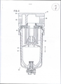
[010] Figura 3 é uma vista em corte total de um filtro que constitui a unidade de pressão de fluido da Figura 1.[010] Figure 3 is a full sectional view of a filter that constitutes the fluid pressure unit of Figure 1.
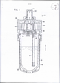
[011] Figura 4 é uma vista em corte completa de um lubrificador que constitui a unidade de pressão de fluido da Figura 1.[011] Figure 4 is a full sectional view of a lubricator that constitutes the fluid pressure unit of Figure 1.
[012] Figura 5 é uma vista em perspectiva externa do dispositivo de conexão ilustrado na Figura 1.[012] Figure 5 is an external perspective view of the connection device illustrated in Figure 1.
[013] Figura 6 é uma vista em perspectiva explodida do dispositivo de conexão da Figura 5.[013] Figure 6 is an exploded perspective view of the connection device of Figure 5.
[014] Figura 7 é uma vista plana das partes principais em um estado em que o filtro e um regulador são conectados usando o dispositivo de conexão ilustrado na Figura 5.[014] Figure 7 is a plan view of the main parts in a state where the filter and a regulator are connected using the connection device illustrated in Figure 5.
[015] Figura 8 é uma vista em corte longitudinal das partes principais em um estado de montagem de um elemento de fixação, um suporte, uma porca e uma tampa que constituem o dispositivo de conexão ilustrado na Figura 5.[015] Figure 8 is a longitudinal sectional view of the main parts in a state of assembly of a fastening element, a support, a nut and a cover that constitute the connection device illustrated in Figure 5.
[016] Figura 9 é uma vista em perspectiva explodida de uma modificação do dispositivo de conexão ilustrado na Figura 5.[016] Figure 9 is an exploded perspective view of a modification of the connection device illustrated in Figure 5.
[017] Figura 10 é uma vista em corte longitudinal das partes principais da modificação do dispositivo de conexão da Figura 9.[017] Figure 10 is a longitudinal sectional view of the main parts of the modification of the connection device of Figure 9.
[018] Um dispositivo de conexão para dispositivos de pressão de fluido de acordo com a presente invenção será descrito em detalhe abaixo com base em uma modalidade preferível com referência aos desenhos anexos.[018] A connecting device for fluid pressure devices according to the present invention will be described in detail below based on a preferred embodiment with reference to the accompanying drawings.
[019] Na Figura 1, o número de referência 10 denota uma unidade de pressão de fluido 10 a que são aplicados os dispositivos de conexão 18a, 18b para dispositivos de pressão de fluido de acordo com a modalidade da presente invenção. Aqui, os componentes dos dispositivos de conexão 18a e os componentes dos dispositivos de conexão 18b são idênticos um ao outro, de modo que um dispositivo de conexão 18a será descrito abaixo. Para o outro dispositivo de conexão 18b, serão dados caracteres de referência idênticos e a descrição detalhada do dispositivo de conexão 18b será omitida.[019] In Figure 1, the
[020] Como ilustrado nas Figuras 1 e 2, esta unidade de pressão de fluido 10 inclui um filtro 12, um regulador 14, um lubrificador 16 e o par de dispositivos de conexão 18a, 18b. O filtro 12 remove o pó e outros, contidos no fluido pressurizado. O regulador 14 reduz a pressão do fluido pressurizado. O lubrificador 16 mistura o óleo lubrificante em relação ao fluido pressurizado. O dispositivo de conexão 18a está disposto entre o filtro 12 e o regulador 14 e o dispositivo de conexão 18b está disposto entre o regulador 14 e o lubrificador 16, conectando assim o filtro 12, o regulador 14 e o lubrificador 16 um com o outro.[020] As illustrated in Figures 1 and 2, this
[021] O filtro 12 acima mencionado, o regulador 14 e o lubrificador 16 funcionam como dispositivos de pressão de fluido com um caminho de fluido no qual o fluido pressurizado é fornecido e estão dispostos de modo que o regulador 14 esteja disposto entre o filtro 12 e o lubrificador 16.[021] The
[022] O filtro 12 inclui um primeiro corpo 20, uma unidade de caixa 22 que está ligada a uma parte inferior do primeiro corpo 20 e uma unidade de filtro 24 que está alojada no interior da unidade de caixa 22, como ilustrado nas Figuras 1 a 3.[022]
[023] No primeiro corpo 20, as primeiras e segundas portas 26, 28 para e a partir das quais o fluido pressurizado é fornecido e descarregado, são proporcionadas nas respectivas porções laterais. A primeira entrada 26 está ligada a um tubo que não é mostrado e através do qual o fluido pressurizado é fornecido. Na segunda entrada 28, o fluido pressurizado fornecido ao primeiro orifício 26 é descarregado em direção ao regulador 14 que será descrito mais tarde.[023] In the
[024] Além disso, nas superfícies laterais do primeiro corpo 20, são proporcionadas, respectivamente, um par de partes de protuberância de encaixe 30a e um par de partes de protrusão de engate 30b. As partes de protrusão de encaixe 30a, 30b são formadas para se fazer face umas às outras nas partes do bordo exterior das superfícies de extremidade nas quais as primeira e segunda aberturas 26, 28 são proporcionadas respectivamente.[024] Furthermore, on the side surfaces of the
[025] A unidade de caixa 22 inclui uma caixa exterior 32 que é formada em uma forma cilíndrica de fundo, uma caixa interior 34 que é inserida no interior da caixa exterior 32, um botão de libertação 36 que é provido para ser livremente deslocável em relação à caixa exterior 32 e uma torneira de drenagem 38 que está provida nas partes inferiores da caixa externa 32 e a caixa interior 34.[025] The
[026] Quando a unidade de caixa 22 está ligada a um furo de fixação 40 do primeiro corpo 20, uma parte de extremidade superior do botão de libertação 36 é inserida em uma parte côncava (não mostrada) que é formada no orifício de fixação 40 do primeiro corpo 20. Consequentemente, o deslocamento da unidade de caixa 22 em uma direção rotativa em relação ao primeiro corpo 20 é regulado.[026] When the
[027] Como ilustrado nas Figuras 1 e 2, o regulador 14 inclui um segundo corpo 42, uma alça 44 que está provida rotativamente em uma parte inferior do segundo corpo 42 e um mecanismo de ajuste de pressão (não mostrado) que é capaz de ajustar a pressão do fluido pressurizado operando a alça 44. Nas porções laterais do segundo corpo 42, um par de orifícios (não mostrados) a partir do qual o fluido pressurizado é fornecido e descarregado são formados respectivamente. Uma das portas está conectada para se comunicar com a segunda entrada 28 do filtro 12 e o fluido pressurizado é fornecido a partir do filtro 12, enquanto a outra das portas está conectada para se comunicar com uma terceira porta 56 (que será descrita mais tarde) do lubrificador 16 e o fluido pressurizado são descarregados.[027] As illustrated in Figures 1 and 2, the
[028] Além disso, nas superfícies laterais do segundo corpo 42, um par de partes de protrusão de encaixe 46a e um par de partes de protrusão de encaixe 46b estão providos respectivamente de modo que as partes de protrusão de encaixe 46a, 46b se faceiam em partes de extremidade externas de superfícies de extremidade sobre as quais um par de portas são fornecidas.[028] Furthermore, on the side surfaces of the
[029] Além disso, o regulador 14 é provido com o mecanismo de ajuste de pressão no mesmo. O regulador 14 aciona o mecanismo de ajuste da pressão rodando a alça 44 para ajustar a pressão do fluido pressurizado que é fornecido de uma porta à pressão desejada e, em seguida, descarrega o fluido pressurizado da outra entrada para fornecer o fluido pressurizado ao lubrificador 16.[029] Furthermore, the
[030] O lubrificador 16 é usado para gotejar óleo lubrificante em fluido pressurizado de modo a fornecer o óleo lubrificante a uma parte deslizante e semelhante em outro dispositivo de pressão de fluido usando um fluxo do fluido pressurizado. Como ilustrado nas Figuras 1, 2 e 4, o lubrificador 16 inclui um terceiro corpo 48, uma unidade de caixa 50 que está ligada a uma parte inferior do terceiro corpo 48, uma peça de gotejamento 52 que é inserida no interior do terceiro corpo 48 e um suporte 54 que fixa a parte de gotejamento 52 para o terceiro corpo 48.[030] The
[031] No terceiro corpo 48, o terceiro orifício 56 e um quarto orifício 58 a partir do qual o fluido pressurizado é fornecido e descarregado são formados respectivamente em porções laterais. A terceira porta 56 e a quarta porta 58 se comunicam entre si através de um caminho de comunicação que não é mostrado. Aqui, a terceira porta 56 está conectada à outra porta do regulador 14 proporcionada adjacentemente, e a quarta entrada 58 está conectada a um tubo que não é mostrado.[031] In the
[032] Além disso, nas superfícies laterais do terceiro corpo 48, são proporcionadas, respectivamente, um par de partes de protrusão de encaixe 60a e um par de partes de protrusão de engate 60b (ver a figura 2). As partes de protrusão de encaixe 60a, 60b são formadas para fazer face uma à outra nas partes do bordo exterior das superfícies de extremidade nas quais as terceira e quarta aberturas 56, 58 são proporcionadas respectivamente.[032] Furthermore, on the side surfaces of the
[033] A unidade de caixa 50 inclui uma caixa exterior 62 que é formada em uma forma cilíndrica de fundo, uma caixa interior 64 que é inserida no interior da caixa exterior 62 e um botão de libertação 66 que é provido para ser deslocável em relação à caixa exterior 62. No interior da caixa interior 64, o óleo lubrificante é preenchido através de um bujão de alimentação de óleo 68 proporcionado no terceiro corpo 48. Além disso, a unidade de caixa 50 está unida a um orifício de fixação 69 do terceiro corpo 48.[033] The
[034] Como ilustrado na Figura 4, a parte de gotejamento 52 inclui um elemento interior 70 que é inserido no interior do terceiro corpo 48 e um bujão de gotejamento 72 que está provido em uma parte superior do elemento interior 70. No elemento interior 70, uma câmara de armazenamento 74 para o qual é fornecido óleo lubrificante a partir da caixa interior 64 é formada. Esta câmara de armazenamento 74 comunica com um percurso de óleo 76 que se estende para baixo e o óleo de lubrificação é fornecido à câmara de armazenamento 74 através deste percurso de óleo 76. Numa parte substancialmente central da câmara de armazenamento 74, uma entrada de gotejamento 78 é aberta para baixo. O percurso de óleo 76 comunica com uma entrada de fornecimento de óleo 82 que é formada no suporte 54.[034] As illustrated in Figure 4, the
[035] O suporte 54 está ligado à parte inferior do elemento interno 70 que constitui a parte de gotejamento 52 e aperta e segura uma parte de um amortecedor 80. Além disso, o suporte 54 inclui a entrada de alimentação de óleo 82 que comunica com a via de óleo 76. Esta entrada de alimentação de óleo 82 está disposta no interior da caixa interior 64 de modo a se projeta para baixo (a direção da seta B) e um tubo de guia de óleo 84 está conectado à entrada de alimentação de óleo 82.[035] The
[036] Além disso, o óleo lubrificante preenchido na caixa interior 64 flui em direção ao suporte 54 através do tubo 84 de guia de óleo, depois é fornecido à câmara de armazenamento 74 através do percurso de óleo 76 e é goteado para um caminho de comunicação a partir da câmara de armazenamento 74 através da porta de gotejamento 78. Assim, uma quantidade desejada de óleo lubrificante é misturada em fluido pressurizado que flui no caminho de comunicação.[036] In addition, lubricating oil filled in the
[037] Como ilustrado nas Figuras 1, 2 e 5 a 7, o dispositivo de conexão 18a (18b) inclui um elemento de base (corpo) 86 que é formado em uma forma de placa fina substancialmente quadrada, um par de primeiro e segundo elementos de fixação 88, 90 que são respectivamente providos em uma superfície lateral e na outra superfície lateral do elemento de base 86, um par de primeiro e segundo suporte 92, 94 que são mantidos, respectivamente, pelos primeiro e segundo elementos de fixação 88, 90 e mantêm os dispositivos de pressão de fluido e um membro acessório 96 que está ligado à outra superfície lateral do elemento de base 86.[037] As illustrated in Figures 1, 2 and 5 to 7, the
[038] O elemento de base 86 é formado para ter uma espessura substancialmente constante. Uma parte de furo 98 é formada em uma parte substancialmente central do elemento de base 86 e um anel de vedação 100 feito de um material elástico está ligado à parte de furo 98. Este anel de vedação 100 é proporcionado de tal modo que uma superfície circunferencial exterior da vedação do anel 100 é encostado em uma superfície circunferencial interna da parte de furo 98.[038] The
[039] Além disso, em uma superfície lateral e na outra superfície lateral do elemento de base 86, formam-se um par de primeira e segunda partes côncavas 102, 104, partes de ranhura 106 e orifícios de comunicação 108. O par de primeira e segunda peças côncavas 102, 104 são rebaixadas em direção à parte de furo 98, e os primeiro e segundo suportes 92, 94, que serão descritos mais adiante, estão respectivamente ligados ao par de primeira e segunda peças côncavas 102, 104 às partes de ranhura 106 são proporcionadas mais próximas da peça de furo 98 do que as primeira e segunda partes côncavas 102, 104. Os orifícios de comunicação 108 permitem a comunicação entre a parte de ranhura 106 e a primeira peça côncava 102 e entre a parte de ranhura 106 e a segunda parte côncava 104.[039] Furthermore, on a side surface and on the other side surface of the
[040] Cada uma das partes de ranhura 106 é um espaço cuja seção tem uma forma retangular e que tem uma abertura. As partes de ranhura 106 são formadas substancialmente paralelas às primeira e segunda partes côncavas 102, 104 e os orifícios de comunicação 108 são respectivamente formados substancialmente nos centros ao longo da direção longitudinal das partes de ranhura 106.[040] Each of the
[041] Além disso, em uma superfície superior e uma superfície inferior do elemento de base 86, são formadas respectivamente um par de peças de flange 110 que se expandem na direção de espessura do elemento de base 86. Por outras palavras, o elemento de base 86 é formado para ter superfícies superiores e inferiores largas.[041] Furthermore, on an upper surface and a lower surface of the
[042] Os primeiro e segundo elementos de fixação 88, 90 incluem uma parte de corpo principal 112 que é formada para ter uma forma de seção substancialmente retangular e uma parte de parafuso (peça de eixo) 114 que é proporcionada no centro na direção longitudinal da parte de corpo principal 112. Os primeiro e segundo elementos de fixação 88, 90 são formados de modo que a peça de parafuso 114 é ortogonal à parte de corpo principal 112, e se projeta por um comprimento predeterminado.[042] The first and
[043] Ou seja, os primeiro e segundo elementos de fixação 88, 90 são formados para ter uma forma em corte substancialmente em forma de T da parte de corpo principal 112 e a parte de parafuso 114. Em outras palavras, a parte de parafuso 114 sobressaia substancialmente do centro, o que é relativamente espessa, da parte do corpo principal 112 de modo a ser ortogonal à direção longitudinal da parte do corpo principal 112 e, por exemplo, a peça de parafuso 114 é um parafuso prisioneiro que tem uma superfície circunferencial externa sobre a qual um parafuso macho é roscado.[043] That is, the first and
[044] Quando o primeiro elemento de fixação 88 é montado como o dispositivo de conexão 18a(b), a parte de corpo principal 112 é inserida na parte de ranhura 106, que é formada em uma superfície lateral do elemento de base 86 e a parte de parafuso 114 do primeiro elemento de fixação 88 é inserido no orifício de comunicação 108, de modo que uma extremidade da peça de parafuso 114 sobressaia na primeira parte côncava 102. Do mesmo modo, a parte de corpo principal 112 é inserida na parte de ranhura 106 que é formada na outra superfície lateral do membro de base 86 e a parte de parafuso 114 do segundo elemento de fixação 90 é inserida no orifício de comunicação 108, de modo que uma extremidade da peça de parafuso 114 sobressaia na segunda parte côncava 104.[044] When the
[045] Além disso, uma vez que os primeiro e segundo elementos de fixação 88, 90 são formados para ter a dimensão da espessura substancialmente igual à dimensão da espessura do elemento de base 86, os primeiro e segundo elementos de fixação 88, 90 não sobressaem na direção da espessura da base membro 86 em um estado em que os primeiro e segundo elementos de fixação 88, 90 estão anexados.[045] In addition, since the first and
[046] Os primeiro e segundo suportes 92, 94 incluem cada um uma peça plana 116 que é formada em uma parte substancialmente central e uma primeira e segunda partes de suporte 118, 120 que são formadas respectivamente em ambas as extremidades da peça plana 116 e estão inclinadas por um ângulo predeterminado de modo que as primeira e segunda partes de suporte 118 e 120 se aproximem mutuamente. Nos primeiro e segundo suportes 92, 94 cada um, as nervuras 119, 121 que se dobram da primeira parte de suporte 118 através da segunda parte de suporte 120 são formadas de forma saliente. As peças planas 116 são inseridas respectivamente nas primeira e segunda partes côncavas 102, 104 do elemento de base 86 e as primeiras partes de suporte 118 e as segundas partes de suporte 120 estão dispostas e encostadas respectivamente nas partes de protrusão envolventes 30b do filtro 12 e as partes de protrusão envolvente 46a do regulador 14.[046] The first and
[047] Os orifícios de parafuso 122 aos quais as peças de parafuso 114 dos primeiro e segundo elementos de fixação 88, 90 são montados de forma livre, respectivamente, são formados substancialmente nos centros das respectivas peças planas 116. O primeiro suporte (retentor) 92 é mantido em relação à peça de parafuso 114 do primeiro elemento de fixação 88 de tal modo que uma primeira porca 126 está engatada por parafuso em um estado em que a peça de parafuso 114 do primeiro elemento de fixação 88 é inserida através do orifício de parafuso 122. Enquanto isso, o segundo suporte 94 é mantido em relação a parte de parafuso 114 do segundo elemento de fixação 90 de tal modo que uma segunda porca 128 é engatada por parafuso em um estado em que a parte de parafuso 114 do segundo elemento de fixação 90 é inserida através. Numa circunferência exterior de uma parte de cabeça 127, que tem uma forma cilíndrica, da primeira porca 126, uma parte côncava-convexa é formada ao longo de uma direção axial. Enquanto isso, em uma superfície circunferencial interna da primeira porca 126, é formado um furo de parafuso 130 no qual é formada uma chave inglesa, que não é mostrada, para ser inserida. Aqui, o número de referência 132 indica uma parte de flange que está integrada com a parte de cabeça 127.[047] The screw holes 122 to which the
[048] Neste caso, na presente modalidade, uma tampa de suporte (referida abaixo como uma tampa) 150 é montada de modo que a tampa 150 rodeie o primeiro suporte 92 e uma parte da primeira porca 126. Conforme entendido a partir das Figuras 6 e 8, a tampa 150 inclui uma parte de superfície curvada 152 que é formada por uma superfície lisa, uma primeira parte de parede lateral 154a e uma segunda parte de parede lateral 154b que estão providas respectivamente em ambas as extremidades da parte de superfície curvada 152 e uma primeira parte plana 156a e uma segunda parte plana 156b que são unidas entre a parte de superfície curvada 152 e as primeira e segunda partes de parede lateral 154a, 154b. Na primeira parte plana 156a e na segunda parte plana 156b, é formada uma parte recortada 157 com uma forma obtida combinando uma forma retangular e uma forma trapezoidal, e uma parte de extremidade do elemento base 86 é inserida na parte recortada 157 em montagem. As primeiras e segundas partes da parede lateral 154a, 154b são realmente grossas. Por conseguinte, os orifícios de iluminação 158a, 158b são formados respectivamente na primeira parte de parede lateral 154a e na segunda parte de parede lateral 154b de modo a reduzir o peso das primeira e segunda partes de parede lateral 154a, 154b.[048] In this case, in the present embodiment, a support cap (referred to below as a cap) 150 is mounted so that the
[049] Além disso, na tampa 150, uma câmara 160 que tem uma forma substancialmente retangular é formada a partir da primeira parte plana 156a através da segunda parte plana 156b, e a câmara 160 comunica com o seu exterior através de um orifício de passagem 162 que é formado na parte curva da superfície 152 e tem uma forma circular. Um diâmetro do orifício de passagem 162 é maior que o da parte de cabeça 127 da primeira porca 126. Entretanto, nas superfícies internas, que estão no lado oposto do orifício de passagem 162, das primeiras e segundas partes de parede lateral 154a, 154b, as superfícies inclinadas 164a, 164b que são abertas para o exterior de uma maneira que se espalham mutuamente são proporcionadas respectivamente. As partes de extremidade das superfícies inclinadas 164a, 164b, as peças de assento 166a, 166b que sobressaem para dentro são proporcionadas respectivamente.[049] Further, in the
[050] É preferível que a tampa 150 possa ser um artigo moldado integralmente que esteja formada integralmente com um material que tenha ligeiramente uma força elástica, e ainda é preferível que a tampa 150 possa ser feita de metal ou resina dura.[050] It is preferred that the
[051] A unidade de pressão de fluido 10 à qual os dispositivos de conexão 18a, 18b de acordo com a modalidade da presente invenção é aplicada é basicamente estruturada como descrito acima. Posteriormente, a montagem do dispositivo de conexão 18a será descrita.[051] The
[052] Primeiro, como o dispositivo de conexão 18a ilustrado na Figura 6, o anel de vedação 100 é inserido na parte de furo 98 do elemento de base 86, enquanto as partes de corpo principal 112 dos primeiro e segundo elementos de fixação 88, 90 são inseridas respectivamente nas partes de ranhura 106 do membro de base 86, as partes de parafuso 114 são inseridas respectivamente nos orifícios de comunicação 108 ao longo da direção axial da peça de furo 98. Consequentemente, um tal estado é produzido que as peças de parafuso 114 dos primeiro e segundo elementos de fixação 88, 90 sobressaem respectivamente para a primeiro e a segunda parte côncavas 102, 104 do elemento de base 86.[052] First, like the connecting
[053] Enquanto isso, a primeira porca 126 é alojada no interior da câmara 160 da tampa 150. Neste momento, através da operação da caixa, a primeira parte de parede lateral 154a e a segunda parte de parede lateral 154b mutuamente ligeiramente espalhadas usando a elasticidade da tampa 150 e as extremidades das primeira e segunda partes de suporte 118 e 120 do primeiro suporte 92 são tornadas a assentar nas peças de assento 166a, 166b da tampa 150. Nesta caixa, a parte de cabeça 127 da primeira porca 126 é exposto ao exterior a partir do orifício de passagem 162 da tampa 150. Consequentemente, a tampa 150 e o primeiro suporte 92 são integrados um com o outro.[053] Meanwhile, the
[054] Posteriormente, as partes planas 116 dos primeiro e segundo suportes 92, 94 são inseridas respectivamente na primeira e segunda peças côncavas 102, 104 enquanto se inserem as peças de parafuso 114 dos primeiro e segundo elementos de fixação 88, 90, respectivamente, através dos orifícios de parafuso 122 dos primeiro e segundo suportes 92, 94. Depois disso, o orifício de parafuso 130 da primeira porca 126 é engatado por parafuso em relação à peça de parafuso 114 do primeiro elemento de fixação 88. Neste momento, a parte de cabeça 127 da primeira porca 126 é exposta ao exterior a partir do orifício de passagem 162 da tampa 150 como descrito acima, de modo que o parafuso pode ser facilmente realizado através da parte de cabeça 127 da primeira porca 126. Neste caso, quando a primeira porca 126 é parafusada, o primeiro elemento de fixação 88 é puxado através da sua parte de parafuso 114. Em outras palavras, a tampa 150 é feita para engatar com a peça de flange 132 da primeira porca 126, de modo que a tampa 150 é deslocada em direção ao membro de base 86 com o primeiro suporte 92 que encosta nas superfícies inclinadas 164a, 164b. Como resultado, a superfície interna da primeira parte de suporte 118 e a superfície interna da segunda parte de suporte 120 do primeiro suporte 92 são feitas para estarem em contato de pressão com a parte de protrusão envolvente 30b do primeiro corpo 20 e a protrusão da parte de engate 46a do segundo corpo 42. Este efeito de contato de pressão espalha a primeira parte de suporte 118 e a segunda peça de suporte 120 do primeiro suporte 92 com uma força resiliente para empurrar as superfícies inclinadas 164a, 164b da tampa 150, fortalecendo ainda mais a integração da tampa 150 e o primeiro suporte 92. A peça de parafuso 114 do segundo elemento de fixação 90 é inserida através de um orifício de passagem 124 que é formado em uma parte substancialmente central do elemento de fixação 96 e, em seguida, a segunda porca 128 é parafuso engatado com a parte de parafuso 114. Consequentemente, a outra superfície lateral do elemento de base 86 está ligada ao elemento de fixação 96 e o primeiro suporte 92 é mantido (fixo) em um lado de superfície lateral do elemento de base 86 ao mesmo tempo.[054] Thereafter, the
[055] Neste caso, é favorável à disposição de realização preliminar de modo que as partes de protrusão envolventes 30b no lado da segunda porta 28 do filtro 12 e as partes de protrusão envolvente 46a do regulador 14 mais próximas da entrada conectada à segunda entrada 28 são feitas estão presos um ao outro, o elemento de base 86 é mantido entre o filtro 12 e o regulador 14, e a segunda entrada 28 e a entrada estão substancialmente alinhadas com a parte de furo 98.[055] In this case, the provision of preliminary realization is favorable so that the enclosing
[056] Enquanto isso, após a primeira e a segunda partes de suporte 118, 120 do segundo suporte 94 são engatadas, respectivamente, com as partes de protrusão 30b, 46a, a segunda porca 128 é parafusa para ser puxada para o elemento de base 86 ao longo da parte de parafuso 114. De acordo, o segundo suporte 94 se move em direção ao membro de base 86. Como resultado, as primeira e segunda partes de suporte 118, 120 do segundo suporte 94 se movem em uma direção que se aproxima mutuamente e a parte de protrusão envolvente 30b do filtro 12 e a parte de protrusão envolvente 46a do regulador 14 é fortemente ligada mutuamente.[056] Meanwhile, after the first and
[057] Neste momento, a segunda entrada 28 do filtro 12 e uma porta do regulador 14 comunicam-se mutuamente através da parte de furo 98 do elemento de base 86 e, ao mesmo tempo, o anel de vedação 100 evita o fluido pressurizado que flui através da parte de orifício 98 de vazamento para o exterior.[057] At this time, the
[058] Aqui, o método de montagem no caso em que o regulador 14 e o lubrificador 16 estão conectados pelo dispositivo de conexão 18b é substancialmente o mesmo que o método de montagem acima descrito, de modo que a sua descrição detalhada será omitida. Além disso, uma ordem de montagem do filtro 12, o regulador 14 e o lubrificador 16 não está limitado à ordem desta descrição.[058] Here, the mounting method in the case where the
[059] Conforme descrito acima, na presente modalidade, o filtro 12, o regulador 14 e o lubrificador 16 que são dispositivos de pressão de fluido podem ser conectados uns aos outros usando impulso ao longo da direção axial das peças de parafuso 114 geradas quando o primeiro e o segundo suportes 92, 94 são fixados pelas primeira e segunda porcas 126, 128. Portanto, o filtro 12, o regulador 14 e o lubrificador 16 podem ser fortemente conectados e uma força pode ser igualmente aplicada em relação aos dispositivos de pressão de fluido adjacentes através do primeiro e segundo suportes 92, 94. Consequentemente, os dispositivos de pressão de fluido podem ser conectados uns aos outros de forma bem balanceada.[059] As described above, in the present embodiment, the
[060] Neste momento, uma vez que a primeira porca 126 e a tampa 150 são integradas com antecedência, o orifício de parafuso 122 do primeiro suporte 92 e o orifício de parafuso 130 da primeira porca 126 podem ser facilmente adaptados ou alinhados na direção axial, facilitando a montagem de trabalho. Além disso, a parte de superfície curvada 152, a primeira parte de parede lateral 154a, a segunda parte de parede lateral 154b e, além disso, as superfícies lisas formadas na primeira parte de plano 156a e a segunda parte de plano 156b da tampa 150 circundam uma parte da primeira porca 126, de modo que a poeira dificilmente se acumula.[060] At this time, since the
[061] Além disso, na unidade de pressão de fluido 10 a qual são aplicados os dispositivos de conexão 18a, 18b que são montados como descrito acima, o fluido pressurizado é fornecido a partir de uma fonte de fornecimento de fluido pressurizado, que não é mostrada, através de um tubo para a primeira entrada 26 do filtro 12, é então introduzido no interior da unidade de caixa 22 a partir do primeiro orifício 26 e passa através de um elemento de filtro da unidade de filtro 24. Consequentemente, o pó e outros, contidos no fluido pressurizado, são removidos de forma favorável. Posteriormente, o fluido pressurizado ascende dentro da unidade de filtro 24 e é descarregado como fluido pressurizado limpo da segunda entrada 28.[061] In addition, in the
[062] Além disso, o fluido pressurizado é fornecido a uma porta (não mostrada) no regulador 14 através da parte de furo 98 do dispositivo de conexão 18a e é ajustado para ter um valor de pressão pré-ajustado pela alça 44, e então o fluido pressurizado submetido ao ajuste de pressão sendo fornecido através da outra entrada ao lubrificador 16 que está integralmente ligado pelo dispositivo de conexão 18b.[062] In addition, pressurized fluid is supplied to a port (not shown) on
[063] Este fluido pressurizado submetido ao ajuste de pressão é fornecido a partir do terceiro orifício 56 do lubrificador 16 para fluir em direção ao quarto orifício 58 e uma parte deste fluido pressurizado é fornecida ao interior da unidade de caixa 50 ao mesmo tempo. Por conseguinte, o óleo lubrificante é empurrado pelo fluido pressurizado fornecido na caixa interior 64, flui para o suporte 54 (a direção da seta A) através do tubo 84 de guia de óleo, depois é fornecido à câmara de armazenamento 74 através do percurso de óleo 76 e é goteado em relação ao fluido pressurizado através da entrada de gotejamento 78. Consequentemente, após o óleo lubrificante ser misturado no fluido pressurizado por uma quantidade predeterminada quando o fluido pressurizado passa através do interior do elemento interno 70, o fluido pressurizado é fornecido a outro dispositivo de pressão de fluido, que requer óleo lubrificante, através de um tubo da quarta porta 58.[063] This pressurized fluid subjected to pressure adjustment is supplied from the
[064] Aqui, é desnecessário dizer que o dispositivo de conexão para dispositivos de pressão de fluido de acordo com a presente invenção não está limitado à modalidade descrita acima e pode empregar vários tipos de estruturas sem se afastar da essência da invenção. Por exemplo, como uma modificação ilustrada nas Figuras 9 e 10, a tampa 150 é ainda mais fina formando partes iluminantes 170, 172 nos lados exteriores da primeira parte de parede lateral 154a e a segunda parte de parede lateral 154b sem formar os orifícios de iluminação 158a, 158b na tampa 150, sendo assim capaz de conseguir mais downsizing do dispositivo de conexão.[064] Here, it is needless to say that the connection device for fluid pressure devices according to the present invention is not limited to the embodiment described above and can employ various types of structures without departing from the essence of the invention. For example, as a modification illustrated in Figures 9 and 10, the
Claims (6)
Applications Claiming Priority (3)
| Application Number | Priority Date | Filing Date | Title |
|---|---|---|---|
| JP2015021948A JP6260793B2 (en) | 2015-02-06 | 2015-02-06 | Connection device for fluid pressure equipment |
| JP2015-021948 | 2015-02-06 | ||
| PCT/JP2016/051827 WO2016125607A1 (en) | 2015-02-06 | 2016-01-22 | Connection devices for fluidic devices |
Publications (2)
| Publication Number | Publication Date |
|---|---|
| BR112017016830A2 BR112017016830A2 (en) | 2018-06-19 |
| BR112017016830B1 true BR112017016830B1 (en) | 2022-02-08 |
Family
ID=56563958
Family Applications (1)
| Application Number | Title | Priority Date | Filing Date |
|---|---|---|---|
| BR112017016830-8A BR112017016830B1 (en) | 2015-02-06 | 2016-01-22 | CONNECTION DEVICE FOR FLUID PRESSURE DEVICES |
Country Status (10)
| Country | Link |
|---|---|
| US (1) | US10738809B2 (en) |
| JP (1) | JP6260793B2 (en) |
| KR (1) | KR101937757B1 (en) |
| CN (1) | CN107208680B9 (en) |
| BR (1) | BR112017016830B1 (en) |
| DE (1) | DE112016000629B4 (en) |
| MX (1) | MX2017010147A (en) |
| RU (1) | RU2679996C9 (en) |
| TW (1) | TWI606204B (en) |
| WO (1) | WO2016125607A1 (en) |
Families Citing this family (6)
| Publication number | Priority date | Publication date | Assignee | Title |
|---|---|---|---|---|
| JP7024662B2 (en) * | 2018-08-24 | 2022-02-24 | 株式会社デンソー | Retainer member |
| US11619346B2 (en) * | 2019-09-14 | 2023-04-04 | Milton Industries, Inc. | Modular digital filter, regulator and lubricator connector and system |
| JP1696416S (en) * | 2020-09-25 | 2021-10-04 | ||
| JP1699985S (en) * | 2020-09-25 | 2021-11-22 | ||
| TWI756903B (en) * | 2020-11-04 | 2022-03-01 | 緯穎科技服務股份有限公司 | Fluid pipeline connection device, fluid pipeline connection assembly and fluid pipeline connection mechanism |
| US11466722B2 (en) * | 2021-03-10 | 2022-10-11 | Hanwit Precision Industries Ltd. | Floating fastener |
Family Cites Families (39)
| Publication number | Priority date | Publication date | Assignee | Title |
|---|---|---|---|---|
| DE547680C (en) | 1930-05-01 | 1932-04-04 | Robert Bosch A G | Alternator with regulator switch, a manually adjustable breaker driven by the machine shaft |
| DE1962911U (en) | 1967-02-08 | 1967-06-29 | Horst Thiel | REFLECTOR CAP. |
| JPS5642518U (en) * | 1979-09-10 | 1981-04-18 | ||
| JPS596695U (en) * | 1982-07-06 | 1984-01-17 | エスエムシ−株式会社 | 3-piece set for pneumatic circuit |
| US4521146A (en) * | 1982-11-08 | 1985-06-04 | Maron Products, Inc. | Lug nut cap |
| FR2545551B1 (en) * | 1983-05-04 | 1985-07-05 | Outillage Air Comprime | CONNECTING FLANGE FOR PNEUMATIC APPARATUS |
| JPS60126785A (en) * | 1983-12-13 | 1985-07-06 | Fujitsu Ltd | Character recognizing system |
| JPS60126785U (en) * | 1984-02-06 | 1985-08-26 | バブコツク日立株式会社 | tightening device |
| US4571133A (en) * | 1984-07-23 | 1986-02-18 | General Motors Corporation | Loading washer assembly |
| DE8813513U1 (en) * | 1988-10-27 | 1989-06-01 | Erich Neumayer Beteiligungs- Und Verwaltungsgesellschaft Mbh & Co Kg, 7613 Hausach, De | |
| US5163797A (en) * | 1991-10-28 | 1992-11-17 | Wheel Masters Inc. | Vehicle lug nut covers |
| US5372392A (en) | 1993-06-24 | 1994-12-13 | Norgren Co. | Connecting devices |
| DE9403481U1 (en) * | 1994-03-02 | 1995-06-29 | Muellenberg Ralph | Clamping arrangement with a cone clamping bolt |
| US5707113A (en) * | 1995-03-08 | 1998-01-13 | Aluminum Company Of America | Wheel cover assembly for a vehicle wheel |
| US5590992A (en) * | 1995-03-08 | 1997-01-07 | Aluminum Company Of America | Cover for a bolt and nut |
| US5688091A (en) * | 1995-09-15 | 1997-11-18 | Hong-Kong Disc Lock Company, Ltd. | Self-locking fastener with captive washer |
| US5951066A (en) * | 1998-02-23 | 1999-09-14 | Erc Industries, Inc. | Connecting system for wellhead components |
| US6102488A (en) * | 1998-02-26 | 2000-08-15 | Industrial & Automotive Fastners, L.L.C. | Torque angle limiting wheelnut |
| US6079923A (en) * | 1998-04-23 | 2000-06-27 | Penn Engineering & Manufacturing Corp. | Hybrid panel fastener |
| US6273658B1 (en) * | 2000-01-27 | 2001-08-14 | S. Allen Patterson | Enclosure for protecting a lug and lug nut |
| DE20007980U1 (en) | 2000-05-03 | 2000-08-03 | Festo Ag & Co | Connecting device |
| US6435791B1 (en) * | 2000-05-19 | 2002-08-20 | Maclean-Fogg Company | Wheel fastener assemblies |
| US6592314B1 (en) * | 2000-10-10 | 2003-07-15 | Industrial And Automotive Fasteners, Llc | Steel washer integral with nut/cap assembly |
| SE517379C2 (en) * | 2000-10-12 | 2002-06-04 | Nord Lock Ab | Fasteners, method of manufacturing a fastener and use of a movable sleeve for the fastener or method |
| US7192234B2 (en) * | 2001-05-31 | 2007-03-20 | Illinois Tool Works Inc. | Integral washer and threaded fastener assembly and method for making same |
| JP3851119B2 (en) | 2001-07-06 | 2006-11-29 | Smc株式会社 | Connection device for fluid pressure equipment |
| US20050047889A1 (en) * | 2003-08-25 | 2005-03-03 | Techmech Technologies Corp. | Fixing member for securing stacked plates |
| SE527663C2 (en) * | 2004-09-28 | 2006-05-02 | Per-Aake Stig Gunnar Wahlberg | Pneumatic system with one or more piston-cylinder arrangements |
| ZA200802601B (en) * | 2005-09-23 | 2009-12-30 | Advanced Building Systems Pty | Swagable washer locking plate |
| RU2407926C2 (en) * | 2006-08-02 | 2010-12-27 | Норгрен, Инк. | Modular rotary connecting system with separate blocking parts and procedure for its assembly |
| JP5276447B2 (en) * | 2006-11-29 | 2013-08-28 | メイラ株式会社 | nut |
| CN201808524U (en) | 2009-11-06 | 2011-04-27 | 李林钢 | Dedicated fixing and sealing device for motor vehicle plate number |
| JP5565634B2 (en) | 2011-05-09 | 2014-08-06 | Smc株式会社 | Connection device for fluid pressure equipment |
| JP5765560B2 (en) * | 2011-05-09 | 2015-08-19 | Smc株式会社 | Filter device |
| DE112011105225T5 (en) | 2011-05-11 | 2014-02-27 | Aktiebolaget Skf | Clutch release |
| US9790974B2 (en) * | 2013-01-02 | 2017-10-17 | Illinois Tool Works Inc. | Twist-in-place grommet connection assembly |
| US9206834B2 (en) * | 2014-03-11 | 2015-12-08 | Hanwit Precision Industries Ltd. | Floating fastener |
| US9909296B2 (en) * | 2014-05-12 | 2018-03-06 | Danco, Inc. | Toilet fastener assembly and method of use |
| US9673602B2 (en) * | 2015-10-02 | 2017-06-06 | Rockwell Automation Technologies, Inc | System for isolating power conductors using cover assemblies |
-
2015
- 2015-02-06 JP JP2015021948A patent/JP6260793B2/en active Active
-
2016
- 2016-01-22 MX MX2017010147A patent/MX2017010147A/en unknown
- 2016-01-22 DE DE112016000629.2T patent/DE112016000629B4/en not_active Expired - Fee Related
- 2016-01-22 CN CN201680008844.8A patent/CN107208680B9/en active Active
- 2016-01-22 BR BR112017016830-8A patent/BR112017016830B1/en active IP Right Grant
- 2016-01-22 RU RU2017131306A patent/RU2679996C9/en active
- 2016-01-22 KR KR1020177024627A patent/KR101937757B1/en active IP Right Grant
- 2016-01-22 WO PCT/JP2016/051827 patent/WO2016125607A1/en active Application Filing
- 2016-01-22 US US15/549,000 patent/US10738809B2/en active Active
- 2016-02-02 TW TW105103272A patent/TWI606204B/en active
Also Published As
| Publication number | Publication date |
|---|---|
| CN107208680B (en) | 2020-01-10 |
| CN107208680B9 (en) | 2020-05-19 |
| WO2016125607A1 (en) | 2016-08-11 |
| JP2016145597A (en) | 2016-08-12 |
| US20180023602A1 (en) | 2018-01-25 |
| CN107208680A (en) | 2017-09-26 |
| DE112016000629B4 (en) | 2020-07-23 |
| RU2679996C9 (en) | 2019-10-02 |
| DE112016000629T8 (en) | 2017-11-23 |
| MX2017010147A (en) | 2017-11-01 |
| TW201638516A (en) | 2016-11-01 |
| RU2679996C1 (en) | 2019-02-14 |
| US10738809B2 (en) | 2020-08-11 |
| BR112017016830A2 (en) | 2018-06-19 |
| DE112016000629T5 (en) | 2017-11-02 |
| KR101937757B1 (en) | 2019-01-11 |
| JP6260793B2 (en) | 2018-01-17 |
| KR20170109049A (en) | 2017-09-27 |
| TWI606204B (en) | 2017-11-21 |
Similar Documents
| Publication | Publication Date | Title |
|---|---|---|
| BR112017016830B1 (en) | CONNECTION DEVICE FOR FLUID PRESSURE DEVICES | |
| US9151449B2 (en) | Vessel attaching/removing device for conditioning apparatus | |
| FR3052921B1 (en) | CONNECTOR | |
| CN103534492B (en) | For the connection device of fluid pressure device | |
| PT1860748E (en) | Watertight electrical equipment to be disposed projecting or embedded in a wall | |
| RU2010104626A (en) | DEVICE FOR CONNECTING VALVE STEM WITH VALVE PLUG | |
| RU2017127548A (en) | THERMALLY COMPENSATED VALVE VALVE COMPONENT | |
| BR112018004070B1 (en) | METAL CUTTING TOOL | |
| JP2009115166A (en) | Fastener | |
| WO2008145779A1 (en) | Safety screw | |
| BR112014029244B1 (en) | COUPLING DEVICE, AND, CUTTING TOOL | |
| BRPI0314305B1 (en) | adapter intermediate ring for a bolted part of a hydraulic locking system | |
| JP2020508865A5 (en) | ||
| US1256706A (en) | Securing means. | |
| BR112020016892A2 (en) | RETENTION DEVICE FOR A THREADED ELEMENT, IN PARTICULAR FOR A NUT | |
| KR20100008381A (en) | Connector for fluid pressure devices | |
| US1779712A (en) | Pipe-nipple connection | |
| KR101053119B1 (en) | Nut integrated bolt | |
| CN112576825B (en) | Nut for pipe joint, fluid pressure device, fluid control system, jig for nut rotation, and screw rotation method | |
| TW202122703A (en) | Fitting nut, fitting, fluid pressure device, and fluid control system, and nut turning tool and fitting nut turning method | |
| ES2562995B1 (en) | Key and screw system or safety nut and procedure for using said system | |
| JPH0433369Y2 (en) | ||
| RU2021116095A (en) | Enclosure with internal locking device | |
| PT104820B (en) | CASE FLOW AND RELATED ASSEMBLY PROCESS | |
| ITTO20080747A1 (en) | FLUID SEALED JUNCTION FOR THE CREATION OF A PRESSURE FLUID POWER SUPPLY CIRCUIT |
Legal Events
| Date | Code | Title | Description |
|---|---|---|---|
| B06F | Objections, documents and/or translations needed after an examination request according [chapter 6.6 patent gazette] | ||
| B06U | Preliminary requirement: requests with searches performed by other patent offices: procedure suspended [chapter 6.21 patent gazette] | ||
| B09A | Decision: intention to grant [chapter 9.1 patent gazette] | ||
| B16A | Patent or certificate of addition of invention granted [chapter 16.1 patent gazette] |
Free format text: PRAZO DE VALIDADE: 20 (VINTE) ANOS CONTADOS A PARTIR DE 22/01/2016, OBSERVADAS AS CONDICOES LEGAIS. |