BR112016000485B1 - ZIPPER SLIDER - Google Patents
ZIPPER SLIDER Download PDFInfo
- Publication number
- BR112016000485B1 BR112016000485B1 BR112016000485-0A BR112016000485A BR112016000485B1 BR 112016000485 B1 BR112016000485 B1 BR 112016000485B1 BR 112016000485 A BR112016000485 A BR 112016000485A BR 112016000485 B1 BR112016000485 B1 BR 112016000485B1
- Authority
- BR
- Brazil
- Prior art keywords
- slider
- handle
- pawl
- tongue
- locking
- Prior art date
Links
Images


Classifications
-
- A—HUMAN NECESSITIES
- A44—HABERDASHERY; JEWELLERY
- A44B—BUTTONS, PINS, BUCKLES, SLIDE FASTENERS, OR THE LIKE
- A44B19/00—Slide fasteners
- A44B19/24—Details
- A44B19/26—Sliders
- A44B19/30—Sliders with means for locking in position
- A44B19/306—Sliders with means for locking in position in the form of a locking spring member actuated by the pull member
-
- A—HUMAN NECESSITIES
- A44—HABERDASHERY; JEWELLERY
- A44B—BUTTONS, PINS, BUCKLES, SLIDE FASTENERS, OR THE LIKE
- A44B19/00—Slide fasteners
- A44B19/24—Details
- A44B19/26—Sliders
- A44B19/262—Pull members; Ornamental attachments for sliders
-
- A—HUMAN NECESSITIES
- A44—HABERDASHERY; JEWELLERY
- A44B—BUTTONS, PINS, BUCKLES, SLIDE FASTENERS, OR THE LIKE
- A44B19/00—Slide fasteners
- A44B19/24—Details
- A44B19/26—Sliders
- A44B19/30—Sliders with means for locking in position
- A44B19/308—Sliders with means for locking in position in the form of a spring-actuated locking member actuated by the pull member
-
- A—HUMAN NECESSITIES
- A44—HABERDASHERY; JEWELLERY
- A44B—BUTTONS, PINS, BUCKLES, SLIDE FASTENERS, OR THE LIKE
- A44B19/00—Slide fasteners
- A44B19/42—Making by processes not fully provided for in one other class, e.g. B21D53/50, B21F45/18, B22D17/16, B29D5/00
Landscapes
- Slide Fasteners (AREA)
Abstract
cursor de zíper deslizante. problema: é fornecido um cursor de zíper com maior capacidade de decoração e tal que é possível montar rapidamente o corpo, o corpo do dente de parada e o puxador do cursor com baixo custo e de forma a economizar espaço. solução: esse cursor de zíper (1), que é tal que o corpo do dente de parada (6) resulta de uma seção de cobertura (63) que se move por meio de uma operação de colapso/montagem do puxador (5) e um dente (61) sendo disposto de forma a possibilitar sua inserção/retirada de um caminho do guia da cremalheira (28) através de um furo no dente (36) ao longo do movimento da seção de cobertura (63), é caracterizado por um puxador (5) com regiões que podem, cada uma, girar em um ângulo predeterminado sem carregar o corpo do dente de parada (6), quando o puxador (5) for completamente colapsado em direção ao lado da abertura traseira (27 e ao lado da abertura lateral (26) com relação ao corpo do cursor (2).sliding zipper cursor. problem: a zipper slider is provided with greater decoration capacity and such that it is possible to quickly assemble the body, stop tooth body and slider handle at low cost and in a space-saving manner. solution: this zipper slider (1), which is such that the body of the stop tooth (6) results from a cover section (63) that moves through a collapsing/assembly operation of the handle (5) and a tooth (61) being arranged to enable its insertion/withdrawal from a guide path of the rack (28) through a hole in the tooth (36) along the movement of the cover section (63), is characterized by a handle (5) with regions that can each rotate at a predetermined angle without loading the stop tooth body (6), when the handle (5) is completely collapsed towards the rear opening side (27 and the side of the lateral opening (26) with respect to the body of the cursor (2).
Description
[0001] A presente invenção refere-se a um deslizador de zíper no qual um tratamento de superfície é realizado e, em particular, a um deslizador de zíper em que um tratamento de superfície pobre pode ser reduzido.[0001] The present invention relates to a zipper slider on which a surface treatment is carried out and, in particular, a zipper slider on which a poor surface treatment can be reduced.
[0002] É convencionalmente conhecido, no campo dos deslizadores utilizados em zíperes, um deslizador com um mecanismo de parada automática no qual, quando a operação de uma lingueta do puxador é parada após um zíper ser aberto ou fechado, trinca de bloqueio montado no deslizador é automaticamente operado para manter o deslizador em uma posição parada e também o referido estado de parada de deslizamento do deslizador pode ser mantido até que a lingueta do puxador não seja mais operada. Além disso, um exemplo específico do deslizador com o referido mecanismo de parada automática é divulgado na Publicação do Pedido de Patente Japonesa n° 2013-31691 (Documento de Patente 1) e similares.[0002] It is conventionally known, in the field of glides used in zippers, a glider with an automatic stop mechanism in which, when the operation of a pawl of the puller is stopped after a zipper is opened or closed, a locking crack is mounted on the glider. is automatically operated to keep the slider in a stopped position and also said slide stop state of the slider can be maintained until the handle pawl is no longer operated. Furthermore, a specific example of the slider with said automatic stop mechanism is disclosed in Japanese Patent Application Publication No. 2013-31691 (Patent Document 1) and the like.
[0003] Por exemplo, é fornecido um deslizador divulgado pelo Documento de Patente 1 em uma lâmina superior respectivo com um sulco de inserção, permitindo que uma trinca de bloqueio seja inserido ali, um furo no linguete fornecido em uma porção da borda da extremidade no lado posterior do terminal da lâmina superior para se estender a partir de uma superfície superior da lâmina superior a uma passagem do guia da cremalheira, saliências de engaste montadas em ambos os lados direito e esquerdo do sulco de inserção em uma porção da extremidade frontal da lâmina superior e porções de retenção da lingueta do puxador direita e esquerda para prender uma lingueta do puxador.[0003] For example, a slider disclosed by Patent Document 1 is provided in a respective upper blade with an insertion groove allowing a locking crack to be inserted therein, a hole in the pawl provided in a portion of the edge of the end in the rear side of the top blade terminal to extend from an upper surface of the top blade to a rack guide passage, crimping lugs mounted on both the left and right sides of the insertion groove in a portion of the front end of the blade top and left and right handle tongue retaining portions for securing a handle tongue.
[0004] Igualmente, a trinca de bloqueio, de acordo com o Documento de Patente 1, tem uma porção de linguete disposta em uma extremidade da trinca de bloqueio para ser inserida através do furo do linguete do corpo do deslizador, uma porção de gancho disposta na outra extremidade da trinca de bloqueio para ser ajustada ao sulco de inserção do corpo do deslizador e uma porção de cobertura fornecida entre a porção do linguete e a porção de gancho para cobrir uma haste de conexão da lingueta do puxador.[0004] Also, the locking crack according to Patent Document 1 has a pawl portion disposed at one end of the locking crack to be inserted through the pawl hole of the slider body, a hook portion disposed at the other end of the locking latch to be fitted to the insertion groove of the body of the slider and a covering portion provided between the pawl portion and the hook portion to cover a connecting rod of the pawl of the handle.
[0005] Além disso, a lingueta do puxador do Documento de Patente 1 tem um corpo da lingueta do puxador, porções de braço direita e esquerda fornecidas para se estender do corpo da lingueta do puxador e uma haste de conexão circular em formato colunar conectando as extremidades iniciais das porções de braço direita e esquerda. Igualmente, no meio da haste de conexão em uma direção direita e esquerda, uma porção em recesso é formada para provocar um corte transversal da haste de conexão para se tornar uma metade do formato circular.[0005] In addition, the knob pawl of Patent Document 1 has a pawl pawl body, right and left arm portions provided to extend from the pawl pawl body, and a circular, columnar-shaped connecting rod connecting the initial ends of the right and left arm portions. Also, in the middle of the connecting rod in a right and left direction, a recessed portion is formed to cause a cross-section of the connecting rod to become a half circular shape.
[0006] Do mesmo modo, no Documento de Patente 1, quando a lingueta do puxador e a trinca de bloqueio, conforme descrito acima, são montados no corpo do deslizador, a haste de conexão da lingueta do puxador é primeiro inserida nas porções de retenção da lingueta do puxador e, então, as porções de retenção da lingueta do puxador são engastadas, desse modo, prendendo de forma giratória a lingueta do puxador no corpo do deslizador. Subsequentemente, um linguete de bloqueio é inserido no sulco de inserção do corpo do deslizador com a lingueta do puxador mantida nele, enquanto é posicionado para permitir que a porção do linguete seja inserida, apesar do furo no linguete do corpo do deslizador. Portanto, o linguete de bloqueio é posicionado em uma posição predeterminada no corpo do deslizador.[0006] Likewise, in Patent Document 1, when the handle pawl and locking crack, as described above, are mounted on the slider body, the handle pawl connecting rod is first inserted into the retaining portions of the handle tongue, and then the handle tongue retaining portions are crimped, thereby pivotally securing the handle tongue to the slider body. Subsequently, a locking pawl is inserted into the insertion groove of the body of the slider with the pawl of the handle held therein, while being positioned to allow the pawl portion to be inserted despite the hole in the pawl of the body of the slider. Therefore, the locking pawl is positioned in a predetermined position on the slider body.
[0007] Então, ao engastar as saliências do corpo do deslizador, a outra extremidade do linguete de bloqueio é fixada de forma engastada, enquanto tem uma folga predeterminada. Dessa maneira, o deslizador do Documento de Patente 1 é montado.[0007] Then, when crimping the protrusions of the slider body, the other end of the locking pawl is fixed in a crimped manner, while having a predetermined clearance. In this way, the Patent Document 1 slider is assembled.
[0008] No caso do deslizador do Documento de Patente 1, montado conforme descrito acima, quando a lingueta do puxador é abaixada em direção ao terminal traseiro, a porção de cobertura do linguete de bloqueio é ajustada na porção em recesso da lingueta do puxador e uma posição do linguete de bloqueio em relação ao corpo do deslizador desce. Consequentemente, a porção do linguete do linguete de bloqueio é inserida na passagem do guia da cremalheira, apesar do furo no linguete do corpo do deslizador.[0008] In the case of the slider of Patent Document 1, assembled as described above, when the pawl of the handle is lowered towards the rear end, the covering portion of the pawl lock is fitted into the recessed portion of the pawl of the pull and a position of the locking pawl relative to the body of the slider descends. Accordingly, the pawl portion of the locking pawl is inserted into the rack guide passage despite the hole in the pawl of the slider body.
[0009] Contrariamente, quando a lingueta do puxador é levantada ou abaixada em direção ao lado da extremidade frontal do deslizador, a porção de cobertura do linguete de bloqueio é levantada pela articulação da haste de conexão da lingueta do puxador, de modo que a porção do linguete do linguete de bloqueio seja removida da passagem do guia da cremalheira. Nesse caso, a outra extremidade do linguete de bloqueio é mantida, enquanto tem a folga predeterminada, conforme descrito acima. Consequentemente, quando a lingueta do puxador é operada para permanecer abaixada ou levantada, a extremidade do linguete de bloqueio é deixada ser movida no sulco de inserção devido à folga, e, desse modo, operações de inserção e remoção da porção de linguete e a partir da passagem do guia da cremalheira podem ser suavemente realizadas.[0009] Conversely, when the pawl of the handle is raised or lowered towards the front end side of the slide, the covering portion of the pawl lock is lifted by the hinge of the connecting rod of the pawl of the handle, so that the of the pawl of the lock pawl is removed from the rack guide passage. In that case, the other end of the locking pawl is held while having the predetermined clearance as described above. Consequently, when the pawl of the handle is operated to remain lowered or raised, the end of the locking pawl is allowed to be moved in the insertion groove due to play, and thereby operations of inserting and removing the pawl portion and from of the rack guide passage can be carried out smoothly.
[00010] Portanto, quando um zíper é construído utilizando o deslizador, por exemplo, se a operação da lingueta do puxador for parada e, então, a lingueta do puxador for abaixada em direção ao terminal traseiro, a porção do linguete do linguete de bloqueio pode projetar-se para a passagem do guia da cremalheira e, desse modo, pode ser projetada com as linhas da cremalheira. Consequentemente, o deslizador é parado em relação às linhas da cremalheira e também a posição de parada pode ser mantida. Contrariamente, se a lingueta do puxador estiver levantada para a finalidade de operação do deslizador, a porção do linguete é removida da passagem do guia da cremalheira e, desse modo, a porção do linguete e as linhas da cremalheira são desengatadas, permitindo, assim, que o deslizador seja suavemente deslizado ao longo das linhas da cremalheira.[00010] Therefore, when a zipper is constructed using the slider, for example, if the pull tab operation is stopped and then the pull tab is lowered towards the rear end, the pawl portion of the locking pawl it can be designed for the rack guide passage and, in this way, it can be designed with the rack lines. Consequently, the slider is stopped with respect to the rack lines and also the stop position can be maintained. Conversely, if the pawl of the handle is raised for the purpose of operating the slider, the pawl portion is removed from the rack guide passage and thereby the pawl portion and rack lines are disengaged, thus allowing for that the slider slides smoothly along the rack lines.
[00011] Documento de Patente:[00011] Patent Document:
[00012] Documento de Patente 1: Publicação do Pedido de[00012] Patent Document 1: Publication of the Application for
[00013] Patente Japonesa Documento n° 2013-31691 de Patente 2: Patente Norte- Americana n° 4391022. SUMÁRIO DA PROBLEMAS INVENÇÃO A SEREM SOLUCIONADOS PELA[00013] Japanese Patent Document No. 2013-31691 of Patent 2: US Patent No. 4391022. SUMMARY OF THE INVENTION PROBLEMS TO BE SOLVED BY
[00014] Conforme descrito acima, o deslizador descrito no Documento de Patente 1 é fornecido com saliências de engaste ou porções de fixação para fixar o linguete de bloqueio à porção da extremidade frontal do corpo do deslizador. Consequentemente, após o linguete de bloqueio se inserido e disposto no sulco de inserção do lâmina superior, as porções de engaste são engastadas ou as porções de fixação são fixadas nas posições predeterminadas na lâmina superior. Desse modo, o linguete de bloqueio pode ser fixado no lâmina superior do corpo do deslizador enquanto permite que a porção do linguete do linguete de bloqueio seja inserida e removida da passagem do guia da cremalheira.[00014] As described above, the slider described in Patent Document 1 is provided with crimping projections or clamping portions to secure the locking pawl to the front end portion of the slider body. Accordingly, after the locking pawl is inserted and disposed in the insertion groove of the upper blade, the crimping portions are crimped or the fixing portions are fixed in predetermined positions on the upper blade. In this way, the pawl can be secured to the upper blade of the body of the slider while allowing the pawl portion of the pawl to be inserted and removed from the rack guide passage.
[00015] Entretanto, no caso onde o linguete de bloqueio e a lingueta do puxador são fixados no lâmina superior do corpo do deslizador, conforme descrito acima, se um tratamento de superfície, tal como chapeamento ou pintura, é realizado após o linguete de bloqueio e a lingueta do puxador serem montados no corpo; um material de tratamento de superfície não pode penetrar nas regiões onde a lingueta do puxador está em contato próximo com o corpo, já que a lingueta do puxador é empurrada contra o corpo devido a uma forma elástica de uma mola do linguete de bloqueio. O tratamento da superfície é provavelmente difícil de ser realizado.[00015] However, in the case where the locking pawl and the handle pawl are fixed to the upper blade of the slider body as described above, if a surface treatment, such as plating or painting, is carried out after the locking pawl and the tongue of the handle are mounted on the body; a surface treatment material cannot penetrate the regions where the pawl of the handle is in close contact with the body, as the pawl of the knob is pushed against the body due to an elastic form of a lock pawl spring. Surface treatment is probably difficult to perform.
[00016] Portanto, no caso de o deslizador ter tal estrutura, o tratamento de superfície é realizado primeiramente em um estado onde o corpo e a lingueta do puxador são montados e, então, o linguete de bloqueio é montado. Desse modo, a fim de montar o deslizador, um processo de montagem da lingueta do puxador no corpo do deslizador e um processo de montagem linguete de bloqueio no corpo do deslizador deverão ser realizados separadamente. Como resultado, são incorridos custos para comprar o respectivo equipamento para realizar cada processo individual, espaços são exigidos para dispor o respectivo equipamento e também horas de trabalho adicionais são necessárias para cada processo individual.[00016] Therefore, in case the slider has such a structure, the surface treatment is carried out first in a state where the handle body and pawl are assembled, and then the locking pawl is assembled. Thus, in order to mount the slide, a process of assembling the pawl of the handle on the body of the slide and a process of assembling the pawl lock on the body of the slide must be carried out separately. As a result, costs are incurred to purchase the respective equipment to carry out each individual process, spaces are required to lay out the respective equipment, and additional man-hours are also required for each individual process.
[00017] Além disso, o linguete de bloqueio é configurado para não ser submetido a um tratamento de superfície. Consequentemente, uma vez que no deslizador montado o linguete de bloqueio tem um aspecto a partir daqueles do corpo e da lingueta do puxador, há espaço para melhoria em termos de decoração.[00017] In addition, the locking pawl is configured not to undergo a surface treatment. Consequently, since in the mounted slider the locking pawl looks like that of the body and pawl of the handle, there is room for improvement in terms of decoration.
[00018] A presente invenção foi feita mantendo em mente os problemas acima citados e um objetivo específico respectivo é fornecer o deslizador de zíper, caracterizado pelos processos de montagem de um corpo do deslizador, linguete de bloqueio e lingueta do puxador poderem ser integral e rapidamente realizados para economizar espaços para o equipamento exigido e reduzir os custos devido às horas de trabalho encurtadas e também a decoração pode ser melhorada.[00018] The present invention was made keeping in mind the above-mentioned problems and a respective specific objective is to provide the zipper slider, characterized in that the assembly processes of a slider body, locking tongue and handle tongue can be fully and quickly carried out to save space for required equipment and reduce costs due to shortened working hours and also the decoration can be improved.
[00019] De acordo com a presente invenção, é fornecido um deslizador de zíper, caracterizado por incluir: um corpo do deslizador, em que as lâminassuperior e inferior são conectados nas extremidades frontais respectivas entre si por um suporte de conexão e uma passagem do guia da cremalheira em forma de Y é disposta entre as lâminas superior e inferior para se estender dos terminais laterais localizados em um lado do suporte de conexão a um terminal traseiro localizado em um lado oposto ao suporte de conexão; uma lingueta do puxador com um corpo para operar o corpo do deslizador, um par de porções de braço fornecido para se estender de uma extremidade do corpo e uma haste de conexão para conectar o par das porções de braço; e um linguete de bloqueio disposto na lâmina superior e com uma porção de linguete em uma extremidade respectiva e uma porção de cobertura fornecida entre uma extremidade e a outra extremidade para cobrir pelo menos uma parte da haste de conexão da lingueta do puxador, em que a lingueta do puxador é mantida de forma giratória na lâmina superior na haste de conexão respectiva; em que o linguete de bloqueio é fixado no corpo do deslizador na outra extremidade respectiva; em que a lingueta do puxador tem uma região giratória, incluindo posições abaixadas onde a lingueta do puxador é abaixada em direção aos terminais laterais e terminal traseiro do corpo do deslizador, e uma posição levantada onde a lingueta do puxador é levantada das posições abaixadas por operação de giro da haste de conexão, em que, dentro da região giratória da lingueta do puxador, o linguete de bloqueio é elasticamente deformado para mover a porção de cobertura e a porção do linguete é disposta para ser inserida e removida da passagem do guia da cremalheira, de acordo com o movimento da porção de cobertura, e em que, quando a lingueta do puxador está completamente definida em direção aos terminais laterais e terminal traseiro em relação ao corpo do deslizador, a lingueta do puxador tem regiões respectivas em que a lingueta do puxador é giratória sobre um ângulo predeterminado sem exercer nenhuma carga no linguete de bloqueio .[00019] According to the present invention, a zipper slide is provided, characterized in that it includes: a slider body, in which the upper and lower blades are connected at the respective front ends to each other by a connecting bracket and a guide passage of the Y-shaped rack is arranged between the upper and lower blades to extend from side terminals located on one side of the connection bracket to a rear terminal located on a side opposite the connection bracket; a pawl of the handle with a body for operating the body of the slider, a pair of arm portions provided for extending from one end of the body, and a connecting rod for connecting the pair of arm portions; and a locking pawl disposed on the upper blade and having a pawl portion at a respective end and a cover portion provided between one end and the other end to cover at least a portion of the pawl connecting rod of the handle, wherein the pawl handle tongue is pivotally held on the upper blade on the respective connecting rod; wherein the locking pawl is secured to the body of the slider at its other end; wherein the pawl of the handle has a pivoting region, including down positions where the pawl of the grip is lowered towards the side ends and rear end of the slider body, and a raised position where the pawl of the grip is raised from the lowered positions by operation pivot of the connecting rod, wherein, within the turning region of the pawl of the handle, the pawl is elastically deformed to move the cover portion, and the pawl portion is arranged to be inserted into and removed from the rack guide passage. , in accordance with the movement of the cover portion, and wherein, when the tongue of the handle is completely set towards the side ends and rear end with respect to the body of the slider, the tongue of the handle has respective regions in which the tongue of the handle is rotatable through a predetermined angle without exerting any load on the locking pawl.
[00020] Também, no deslizador de zíper, de acordo com a presente invenção, a haste de conexão da lingueta do puxador tem uma porção do cursor formada para sobressair-se de um lado da extremidade da base respectiva em direção a um lado da extremidade inicial; caracterizado pela porção do cursor ter as superfícies primária e secundária inclinadas, respectivamente, nos lados frontal e traseiro da lingueta do puxador; em que as superfícies primária e secundária inclinadas são inclinadas em tal direção que as superfícies inclinadas se aproximam uma da outra do lado da extremidade da base em direção ao lado da extremidade inicial; em que, quando a lingueta do puxador é completamente abaixada em direção ao terminal traseiro em relação ao corpo do deslizador, um ângulo predeterminado é formado entre a superfície primária inclinada da porção do cursor e uma superfície inferior de uma porção da placa superior da porção de cobertura do linguete de bloqueio ; e em que, quando a lingueta do puxador é completamente abaixada em direção aos terminais laterais em relação ao corpo do deslizador, um ângulo predeterminado é formado entre a superfície secundária inclinada da porção do cursor e a superfície inferior da porção da placa superior da porção de cobertura do linguete de bloqueio .[00020] Also, in the zipper slider according to the present invention, the tongue connecting rod of the puller has a slider portion formed to protrude from an end side of the respective base toward an end side. initial; characterized in that the slider portion has the primary and secondary surfaces angled, respectively, on the front and rear sides of the handle tongue; wherein the primary and secondary sloped surfaces are sloped in such a direction that the sloped surfaces approach each other from the base end side towards the leading end side; wherein, when the pawl of the handle is fully lowered toward the rear end with respect to the body of the slider, a predetermined angle is formed between the sloped primary surface of the slider portion and a lower surface of an upper plate portion of the slider portion. lock pawl cover ; and wherein, when the pawl of the handle is fully lowered towards the side ends with respect to the body of the slider, a predetermined angle is formed between the sloped secondary surface of the slider portion and the lower surface of the upper plate portion of the slider portion. lock pawl cover .
[00021] Além disso, no deslizador de zíper, de acordo com a presente invenção, a porção do cursor é configurada para ter uma porção da extremidade inicial em forma de arco circular, conectando as superfícies primária e secundária inclinadas; e em que a porção do cursor é formada, de modo que uma linha reta que passa através de um centro giratório do lado da extremidade da base da porção do cursor e se estende em uma direção longitudinal da lingueta do puxador e uma linha reta que passa através de um centro radial do lado da extremidade inicial da porção do cursor e do centro giratório do lado da extremidade da base respectiva sejam intersectadas entre si.[00021] Furthermore, in the zipper slider according to the present invention, the slider portion is configured to have a circular arc-shaped leading end portion connecting the angled primary and secondary surfaces; and wherein the slider portion is formed such that a straight line passing through a pivotal center on the base end side of the slider portion and extending in a longitudinal direction from the handle tongue and a straight line passing through through a radial center on the leading end side of the slider portion and the pivotal center on the end side of the respective base are intersected with each other.
[00022] Além disso, no deslizador de zíper, de acordo com a presente invenção, uma porção de montagem com uma superfície superior posicionada acima da superfície superior da lâmina superior é formada na superfície superior da lâmina superior; e em que a haste de conexão da lingueta do puxador é instalada no corpo do deslizador para ser encostada contra a superfície superior da porção de montagem.[00022] Further, in the zipper slider according to the present invention, a mounting portion with an upper surface positioned above the upper surface of the upper blade is formed on the upper surface of the upper blade; and wherein the tongue connecting rod of the handle is installed in the body of the slider to be abutted against the upper surface of the mounting portion.
[00023] Além disso, no deslizador de zíper, de acordo com a presente invenção, as porções escalonadas com uma superfície escalonada são formada nas respectivas extremidades laterais da superfície superior da lâmina superior, que são localizadas em direção ao terminal traseiro; em que as porções escalonadas são configuradas para ter uma superfície inferior escalonada posicionada abaixo da superfície superior da lâmina superior; e em que, quando a lingueta do puxador é abaixada em direção ao terminal traseiro, a lingueta do puxador e o corpo do deslizador têm uma relação em que a lingueta do puxador é encostada contra a superfície superior da lâmina superior e lacunas entre as superfícies inferiores escalonadas e a lingueta do puxador são criadas.[00023] Furthermore, in the zipper slider according to the present invention, stepped portions with a stepped surface are formed at respective lateral ends of the upper surface of the upper blade, which are located towards the rear end; wherein the stepped portions are configured to have a stepped lower surface positioned below the upper surface of the upper blade; and wherein, when the pawl of the handle is lowered towards the rear end, the pawl of the knob and the body of the slide have a relationship in which the pawl of the knob is flush against the upper surface of the upper blade and gaps between the lower surfaces staggered and the handle tongue are created.
[00024] Além disso, no deslizador de zíper, de acordo com a presente invenção, na posição abaixada onde a lingueta do puxador é completamente abaixada em direção ao terminal traseiro em relação ao corpo do deslizador, o ângulo α entre a superfície primária inclinada da porção do cursor e a superfície inferior da porção da placa superior da porção de cobertura do linguete de bloqueio é 10° < α < 35°; e em que na posição abaixada onde a lingueta do puxador é completamente abaixada em direção aos terminais laterais em relação ao corpo do deslizador, o ângulo β entre a superfície secundária inclinada da porção do cursor e a superfície inferior da porção da placa superior da porção de cobertura do linguete de bloqueio é 10° < β < 35°.[00024] Furthermore, in the zipper slider according to the present invention, in the lowered position where the tongue of the puller is completely lowered towards the rear end with respect to the body of the slider, the angle α between the inclined primary surface of the slider portion and the lower surface of the upper plate portion of the locking pawl covering portion is 10° < α < 35°; and wherein in the lowered position where the pawl of the handle is fully lowered towards the side ends with respect to the body of the slider, the angle β between the sloped secondary surface of the slider portion and the lower surface of the upper plate portion of the slider portion lock pawl coverage is 10° < β < 35°.
[00025] Além disso, no deslizador de zíper, de acordo com a presente invenção, a lingueta do puxador é configurada para ser giratória em relação ao corpo do deslizador dentro de uma faixa de 0° ou mais e 5° ou menos de uma posição levantada, onde uma direção longitudinal da lingueta do puxador é paralela à superfície superior da lâmina superior, em direção às respectivas posições abaixadas.[00025] Furthermore, in the zipper slider according to the present invention, the tongue of the puller is configured to be rotatable with respect to the body of the slider within a range of 0° or more and 5° or less of a position raised, where a longitudinal direction of the handle tongue is parallel to the upper surface of the upper blade, towards the respective lowered positions.
[00026] Além disso, no deslizador de zíper, de acordo com a presente invenção, o corpo do deslizador, a lingueta do puxador e o linguete de bloqueio têm superfícies submetidas ao mesmo tratamento de superfície.[00026] Furthermore, in the zipper slider according to the present invention, the slider body, the pull tab and the locking tab have surfaces subjected to the same surface treatment.
[00027] Além disso, de acordo com a presente invenção, há um método de fabricação do deslizador de zíper, o deslizador de zíper incluindo: um corpo do deslizador em que as lâminas superior e inferior são conectados nas extremidades frontais respectivas um ao outro por um suporte de conexão e uma passagem do guia da cremalheira em forma de Y é disposta entre as lâminas superior e inferior para se estender dos terminais laterais localizados em um lado do suporte de conexão para o terminal traseiro localizados em um lado oposto ao suporte de conexão; uma lingueta do puxador com um corpo para operar o corpo do deslizador, um par de porções de braço fornecida para se estender de uma extremidade do corpo e uma haste de conexão para conectar o par das porções de braço; e um linguete de bloqueio disposto na lâmina superior e com uma porção de linguete em uma extremidade respectiva e uma porção de cobertura fornecida entre uma extremidade e a outra extremidade para cobrir pelo menos uma parte da haste de conexão da lingueta do puxador, em que a lingueta do puxador tem uma região giratória incluindo posições abaixadas onde a lingueta do puxador é abaixada em direção aos terminais laterais e terminal traseiro do corpo do deslizador, e uma posição levantada onde a lingueta do puxador é levantada a partir das posições abaixadas pela operação de giro da haste de conexão, o método compreendendo: uma etapa de montagem da lingueta do puxador e do linguete de bloqueio no corpo do deslizador, de modo que dentro da região giratória da lingueta do puxador, a lingueta do puxador tenha: uma primeira região giratória na qual o linguete de bloqueio é elasticamente deformado para mover a porção de cobertura; uma segunda região giratória entre a primeira região giratória e a posição abaixada em direção aos terminais laterais, onde a lingueta do puxador é giratória sobre um ângulo predeterminado sem exercer nenhuma carga no linguete de bloqueio ; e uma terceira região giratória entre a primeira região giratória e a posição abaixada em direção ao terminal traseiro, onde a lingueta do puxador é giratória sobre um ângulo predeterminado sem exercer nenhuma carga no linguete de bloqueio ; e uma etapa de tratamento de superfície para tratamento da superfície do deslizador de zíper com o corpo do deslizador, a lingueta do puxador e o linguete de bloqueio montados durante a etapa de montagem.[00027] Further, according to the present invention, there is a method of manufacturing the zipper slider, the zipper slider including: a slider body wherein the upper and lower blades are connected at respective front ends to each other by a connecting bracket and a Y-shaped rack guide passage is arranged between the upper and lower blades to extend from the side terminals located on one side of the connecting bracket to the rear terminal located on a side opposite the connecting bracket ; a pawl of the handle with a body for operating the body of the slider, a pair of arm portions provided for extending from one end of the body, and a connecting rod for connecting the pair of arm portions; and a locking pawl disposed on the upper blade and having a pawl portion at a respective end and a cover portion provided between one end and the other end to cover at least a portion of the pawl connecting rod of the handle, wherein the pawl The handle tongue has a pivot region including down positions where the handle tongue is lowered toward the side and rear ends of the slider body, and a raised position where the handle tongue is raised from the lowered positions by the turning operation. of the connecting rod, the method comprising: a step of assembling the handle pawl and the locking pawl to the body of the slider, so that within the turning region of the knob pawl, the pawl pawl has: a first pivoting region in the which the locking pawl is elastically deformed to move the cover portion; a second swivel region between the first swivel region and the lowered position towards the side ends, where the pawl of the handle is pivoted through a predetermined angle without exerting any load on the locking pawl; and a third swivel region between the first swivel region and the lowered position towards the rear end, where the pawl of the handle is pivoted through a predetermined angle without exerting any load on the locking pawl; and a surface treatment step for treating the surface of the zipper slide with the slider body, the pull tab and the locking pawl assembled during the assembly step.
[00028] De acordo com o deslizador de zíper da presente invenção, o deslizador de zíper pode ser fornecido, no qual os processos de montagem de um corpo do deslizador, um linguete de bloqueio e uma lingueta do puxador podem ser integral e rapidamente realizados para economizar espaços para o equipamento exigido e reduzir custos devido às horas de trabalho encurtadas e também a decoração pode ser melhorada.[00028] In accordance with the zipper slider of the present invention, the zipper slider can be provided, in which the processes of assembling a slider body, a locking pawl and a puller pawl can be integrally and quickly performed to save space for required equipment and reduce cost due to shortened working hours and also the decoration can be improved.
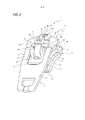
[00029] A figura 1 é uma visualização em perspectiva, mostrando um estado expandido dos componentes, de acordo com o deslizador de zíper da presente aplicação.[00029] Figure 1 is a perspective view, showing an expanded state of the components, according to the zipper slider of the present application.
[00030] A figura 2 é uma visualização em perspectiva, mostrando um estado montado do deslizador da presente aplicação.[00030] Figure 2 is a perspective view, showing an assembled state of the slider of the present application.
[00031] A figura 3 é uma visualização lateral, mostrando um estado onde uma lingueta do puxador é abaixada em direção a um terminal traseiro para ficar paralela a uma superfície superior de uma lâmina superior respectivo, de acordo com o deslizador da presente aplicação.[00031] Figure 3 is a side view, showing a state where a pawl of the handle is lowered towards a rear end to be parallel to an upper surface of a respective upper blade, in accordance with the slider of the present application.
[00032] A figura 4 é uma visualização em corte, conforme tomada ao longo de uma direção frontal e traseira, mostrando um estado onde a lingueta do puxador é abaixada em direção ao terminal traseiro para ficar paralela à superfície superior da lâmina superior, de acordo com o deslizador da presente aplicação.[00032] Figure 4 is a sectional view, as taken along a front and rear direction, showing a state where the pawl of the handle is lowered towards the rear end to be parallel to the upper surface of the upper blade, in accordance with with the slider of the present application.
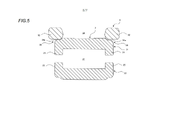
[00033] A figura 5 é uma visualização em corte, conforme tomada ao longo de uma direção direita e esquerda, mostrando um estado onde a lingueta do puxador é completamente abaixada em direção ao terminal traseiro, de acordo com o deslizador da presente aplicação.[00033] Figure 5 is a sectional view, as taken along a right and left direction, showing a state where the handle tongue is fully lowered towards the rear end, in accordance with the slider of the present application.
[00034] A figura 6 é uma visualização em corte ampliada, conforme tomada ao longo da direção frontal e traseira, mostrando a proximidade de uma porção do cursor no estado onde a lingueta do puxador é completamente abaixada em direção ao terminal traseiro, de acordo com o deslizador da presente aplicação.[00034] Figure 6 is an enlarged sectional view, as taken along the front and rear direction, showing the proximity of a portion of the slider in the state where the pawl of the handle is fully lowered towards the rear end, in accordance with the slider of the present application.
[00035] A figura 7 é uma visualização em corte ampliada, conforme tomada ao longo da direção frontal e traseira, mostrando a proximidade da porção do cursor quando a lingueta do puxador é levantada do estado, onde a lingueta do puxador é completamente abaixada em direção ao terminal traseiro, de modo que a porção do cursor seja encostada contra um linguete de bloqueio , de acordo com o deslizador da presente aplicação.[00035] Figure 7 is an enlarged sectional view, as taken along the front and rear direction, showing the proximity of the slider portion when the handle pawl is lifted from the state where the knob pawl is fully lowered toward to the rear end, so that the slider portion is abutted against a locking pawl, in accordance with the slider of the present application.
[00036] A figura 8 é uma visualização em corte ampliada, conforme tomada ao longo da direção frontal e traseira, mostrando a proximidade da porção do cursor no estado onde a lingueta do puxador é completamente abaixada em direção aos terminais laterais, de acordo com o deslizador da presente aplicação.[00036] Figure 8 is an enlarged sectional view, as taken along the front and rear direction, showing the proximity of the slider portion in the state where the handle pawl is fully lowered towards the side terminals, in accordance with the slider of the present application.
[00037] A figura 9 é uma visualização em corte ampliada, conforme tomada ao longo da direção frontal e traseira, mostrando a proximidade da porção do cursor quando a lingueta do puxador é levantada do estado, onde a lingueta do puxador é completamente abaixada em direção aos terminais laterais, de modo que a porção do cursor seja encostada contra o linguete de bloqueio de acordo com o deslizador da presente aplicação.[00037] Figure 9 is an enlarged sectional view, as taken along the front and rear direction, showing the proximity of the cursor portion when the handle pawl is lifted from the state where the knob pawl is fully lowered toward to the side terminals so that the slider portion is abutted against the locking pawl in accordance with the slider of the present application.
[00038] Agora, as aplicações da presente invenção serão descritas em detalhes com referência aos desenhos anexos.[00038] Now, applications of the present invention will be described in detail with reference to the accompanying drawings.
[00039] A figura 1 é uma visualização em perspectiva, mostrando um estado expandido dos componentes, de acordo com o deslizador de zíper da presente aplicação. A figura 2 é uma visualização em perspectiva, mostrando um estado montado do deslizador da presente aplicação. A figura 3 é uma visualização lateral, mostrando um estado onde a lingueta do puxador é abaixada em direção a um terminal traseiro para ficar paralela a uma superfície superior de uma lâmina superior respectivo, de acordo com o deslizador da presente aplicação. A figura 4 é uma visualização em corte, conforme tomada ao longo de uma direção frontal e traseira, mostrando um estado onde a lingueta do puxador é abaixada em direção ao terminal traseiro para ficar paralela à superfície superior da lâmina superior, de acordo com o deslizador da presente aplicação. A figura 5 é uma visualização em corte, conforme tomada ao longo de uma direção direita e esquerda, mostrando um estado onde a lingueta do puxador é completamente abaixada em direção ao terminal traseiro, de acordo com o deslizador da presente aplicação.[00039] Figure 1 is a perspective view, showing an expanded state of the components, according to the zipper slider of the present application. Figure 2 is a perspective view showing an assembled state of the slider of the present application. Figure 3 is a side view showing a state where the tongue of the handle is lowered towards a rear end to be parallel to an upper surface of a respective upper blade, in accordance with the slider of the present application. Figure 4 is a sectional view, as taken along a front and rear direction, showing a state where the pawl of the handle is lowered towards the rear end to be parallel to the upper surface of the upper blade, in accordance with the slider. of the present application. Fig. 5 is a sectional view, as taken along a right and left direction, showing a state where the latch of the handle is fully lowered towards the rear end, in accordance with the slider of the present application.
[00040] Enquanto isso, com respeito ao deslizador de zíper (1), de acordo com a presente invenção, uma direção frontal refere-se a uma direção ao longa da qual o deslizador (1) é deslizado para engatar as linhas da cremalheira uma com a outra, e uma direção traseira refere- se a uma direção ao longo da qual o deslizador é deslizado para desengatar as linhas da cremalheira uma da outra. Também, uma direção a montante e a jusante refere-se a uma direção perpendicular aas lâminas superior e inferior (21 e 22) e uma direção direita e esquerda refere-se a uma direção paralela aas lâminas superior e inferior (21 e 22) e também perpendicular à direção de deslizamento do deslizador (1).[00040] Meanwhile, with respect to the zipper slider (1), according to the present invention, a forward direction refers to a direction along which the slider (1) is slid to engage the rack lines one at a time. with the other, and a backward direction refers to a direction along which the slider is slid to disengage the rack lines from each other. Also, an upstream and downstream direction refers to a direction perpendicular to the upper and lower blades (21 and 22) and a right and left direction refers to a direction parallel to the upper and lower blades (21 and 22) and also perpendicular to the sliding direction of the slider (1).
[00041] Conforme mostrado na figura 1, o deslizador (1), de acordo com a presente aplicação, inclui um corpo do deslizador (2), uma lingueta do puxador (5) mantida de forma giratória no corpo do deslizador (2) em uma extremidade respectiva e um linguete de bloqueio (6) disposto no corpo do deslizador (2). De acordo com o deslizador (1) da presente aplicação, o corpo do deslizador (2) e a lingueta do puxador (5) são feitos de materiais metálicos, tais como liga de alumínio, liga de zinco e liga de cobre, por fundição em molde ou prensagem. Também, o linguete de bloqueio (6) é feito de um material de metal altamente elástico, tal como aço inoxidável ou liga de cobre, por prensagem.[00041] As shown in figure 1, the slider (1), according to the present application, includes a slider body (2), a handle pawl (5) rotatably held in the slider body (2) in a respective end and a locking pawl (6) arranged on the body of the slider (2). According to the slide (1) of the present application, the body of the slide (2) and the tongue of the handle (5) are made of metallic materials, such as aluminum alloy, zinc alloy and copper alloy, by casting in mold or pressing. Also, the locking pawl (6) is made of a highly elastic metal material, such as stainless steel or copper alloy, by pressing.
[00042] O corpo do deslizador (2) tem uma lâmina superior (21), uma lâmina inferior (22) e um suporte de conexão (23) para conectar as extremidades frontais das lâminas superior e inferior (21 e 22). As porções de flange superior (24) são suspensas dos lados direito e esquerdo da lâmina superior (21) em uma direção perpendicular aa lâmina superior (21), e porções de flange inferior (25) são erigidas dos lados direito e esquerdo da lâmina inferior (22) em uma direção perpendicular aa lâmina inferior (22).[00042] The body of the slider (2) has an upper blade (21), a lower blade (22) and a connecting bracket (23) for connecting the front ends of the upper and lower blades (21 and 22). Upper flange portions (24) are suspended from the right and left sides of the upper blade (21) in a direction perpendicular to the upper blade (21), and lower flange portions (25) are erected from the right and left sides of the lower blade. (22) in a direction perpendicular to the lower blade (22).
[00043] Além disso, o corpo do deslizador (2) tem terminais laterais (26) dispostos em ambos os lados direito e esquerdo do suporte de conexão (23), um terminal traseiro (27) disposto em uma extremidade traseira respectiva e uma passagem do guia da cremalheira em forma de Y (28) formada entre a lâmina superior e inferior (21 e 22) para conectar os terminais laterais direito e esquerdo (26) com o terminal traseiro (27).[00043] In addition, the body of the slider (2) has side terminals (26) disposed on both the right and left sides of the connection bracket (23), a rear terminal (27) disposed at a respective rear end and a passage Y-shaped rack guide (28) formed between the upper and lower blade (21 and 22) to connect the right and left side terminals (26) with the rear terminal (27).
[00044] A lâmina superior (21) do corpo do deslizador (2) tem porções de retenção da lingueta do puxador direita e esquerda (31) para prender de forma giratória uma extremidade da lingueta do puxador (5), um sulco de inserção (32) disposto no meio de uma superfície superior da lâmina superior (21) na direção direita e esquerda e configurado para permitir que o linguete de bloqueio (6) seja inserido nele, uma porção em recesso (33) fornecida de forma côncava em uma extremidade frontal da lâmina superior (21), um par de porções de fixação direita e esquerda (34) erigido a partir de uma superfície inferior da porção em recesso (33), e porções levantadas dispostas em ambos os lados direito e esquerdo do sulco de inserção (32) e, também, entre as porções de retenção da lingueta do puxador (31) e a porção em recesso (33) e levantadas a partir da superfície superior da lâmina superior (21).[00044] The upper blade (21) of the body of the slider (2) has right and left handle pawl retaining portions (31) for pivotally securing one end of the pawl pawl (5), an insertion groove ( 32) disposed in the middle of an upper surface of the upper blade (21) in the right and left direction and configured to allow the locking pawl (6) to be inserted therein, a recessed portion (33) provided concavely at one end front of the upper blade (21), a pair of right and left attachment portions (34) erected from a lower surface of the recessed portion (33), and raised portions disposed on both the right and left sides of the insertion groove (32) and also between the tongue retaining portions of the handle (31) and the recessed portion (33) and raised from the upper surface of the upper blade (21).
[00045] Enquanto isso, conforme descrito abaixo, as porções de fixação (34) são engastadas em direções que se aproximam uma da outra para fixar o linguete de bloqueio (6) ao corpo do deslizador (2), mas a fixação pode não ser necessária para ser realizada por engaste. Por exemplo, conforme divulgado representativamente nas figuras 3 e 4 do Documento de Patente 2, o linguete de bloqueio pode ser fixado através de acoplamento elástico de uma extremidade inicial do linguete de bloqueio com uma porção de fixação formada em uma parede interna de um furo fornecido no posto guia.[00045] Meanwhile, as described below, the clamping portions (34) are crimped in directions approaching each other to secure the locking pawl (6) to the slider body (2), but the clamping may not be required to be carried out by setting. For example, as representatively disclosed in Figures 3 and 4 of
[00046] Cada uma das porções de retenção da lingueta do puxador (31) inclui um par de saliências frontais e traseiras (31a) formadas para projetar-se nos respectivos lados direito e esquerdo do furo de inserção (32) em uma localização que é situada em direção ao terminal traseiro (27) e uma porção de montagem (31b) configurada para permitir que uma parte da lingueta do puxador (5) seja montada entre as saliências direita e esquerda (31a). Uma haste de conexão (53), conforme descrito abaixo, da lingueta do puxador (5) pode ser mantida de forma giratória nas porções de retenção da lingueta do puxador (31), através da inserção da haste de conexão (53) da lingueta do puxador (5) entre as saliências frontais e traseiras (31a) para serem montadas na porção de montagem (31b) e, então, flexionar e frisar o par de saliências frontais e traseiras (31a) na direção que se aproxima uma da outra. Enquanto isso, a porção de montagem (31b) tem uma superfície superior levantada acima da superfície superior da lâmina superior (21) e uma parte da haste de conexão (53) da lingueta do puxador (5) é montada na superfície superior da porção de montagem (31b).[00046] Each of the tongue retaining portions of the handle (31) includes a pair of front and rear projections (31a) formed to project on the respective left and right sides of the insertion hole (32) at a location that is situated towards the rear end (27) and a mounting portion (31b) configured to allow a portion of the handle tongue (5) to be mounted between the right and left protrusions (31a). A connecting rod (53), as described below, of the handle pawl (5) can be pivotally held in the retaining portions of the knob pawl (31) by inserting the connecting rod (53) of the pawl pawl (31). handle (5) between the front and rear lugs (31a) to be mounted on the mounting portion (31b) and then flex and crimp the pair of front and rear lugs (31a) in the direction they approach each other. Meanwhile, the mounting portion (31b) has an upper surface raised above the upper surface of the upper blade (21) and a part of the connecting rod (53) of the pawl of the handle (5) is mounted on the upper surface of the upper blade portion (21). assembly (31b).
[00047] O sulco de inserção (32) tem uma largura de sulco igual a ou ligeiramente maior que uma dimensão do linguete de bloqueio (6) na direção direita e esquerda, permitindo, desse modo, que o linguete de bloqueio (6) seja estavelmente inserido ali. Também, em uma localização no sulco de inserção (32), que é localizado em direção ao terminal traseiro (27), uma etapa correspondendo a um formato do linguete de bloqueio (6) é fornecida uma forma gradual em uma direção longitudinal do sulco de inserção (32).[00047] The insertion groove (32) has a groove width equal to or slightly greater than a dimension of the locking pawl (6) in the right and left direction, thereby allowing the locking pawl (6) to be stably inserted there. Also, at a location in the insertion groove (32), which is located towards the rear end (27), a step corresponding to a shape of the locking pawl (6) is provided a gradual shape in a longitudinal direction of the insertion groove (6). insertion (32).
[00048] A porção em recesso (33) é fornecida de forma côncava em um lado da superfície superior do sulco de inserção (32) em uma porção da extremidade frontal da lâmina superior (21) ao qual o suporte de conexão (23) está conectado. Uma porção de gancho (62) do linguete de bloqueio (6) é encostada e suportada contra a porção em recesso (33).[00048] The recessed portion (33) is provided concavely on one side of the upper surface of the insertion groove (32) on a front end portion of the upper blade (21) to which the connection bracket (23) is attached. connected. A hook portion (62) of the locking pawl (6) is abutted and supported against the recessed portion (33).
[00049] As porções de fixação (34) no deslizador (1) da presente aplicação são erigidas a partir de uma superfície inferior da lâmina superior (21). As porções de fixação direita e esquerda (34) são curvadas e engastadas para dentro após o linguete de bloqueio (6) ser inserido no sulco de inserção (32) da lâmina superior (21).[00049] The attachment portions (34) on the slider (1) of the present application are erected from a lower surface of the upper blade (21). The right and left clamping portions (34) are curved and crimped inwardly after the locking pawl (6) is inserted into the insertion groove (32) of the upper blade (21).
[00050] As porções levantadas (35) são dispostas para projetar-se a partir da superfície superior da lâmina superior (21) em ambos os lados direito e esquerdo do sulco de inserção (32). Ao dispor essas porções levantadas (35) dessa maneira, o linguete de bloqueio (6) pode ser escondido menos visivelmente pelas porções levantadas (35) na direção direita e esquerda para prevenir o linguete de bloqueio (6) de ressaltar a montante a partir do interior do sulco de inserção (32), por exemplo, mesmo se uma parte do linguete de bloqueio (6) é movido a montante acima da superfície superior da lâmina superior (21) quando o linguete de bloqueio (6) está disposto no sulco de inserção (32) e, também, o linguete de bloqueio (6) é movido a montante ou a jusante para dentro do sulco de inserção (32) pela operação da lingueta do puxador (5), melhorando, desse modo, a aparência do deslizador (1).[00050] Raised portions (35) are arranged to project from the upper surface of the upper blade (21) on both the right and left sides of the insertion groove (32). By arranging these raised portions (35) in this way, the locking pawl (6) can be hidden less visibly by the raised portions (35) in the right and left direction to prevent the locking pawl (6) from protruding upstream from the interior of the insertion groove (32), for example, even if a part of the locking pawl (6) is moved upstream above the upper surface of the upper blade (21) when the locking pawl (6) is arranged in the locking groove (21). insert (32) and also the locking pawl (6) is moved upstream or downstream into the insertion groove (32) by operating the pawl of the handle (5), thereby improving the appearance of the slider (1).
[00051] Igualmente, em uma localização no deslizador (1) que está situada entre as porções de retenção da lingueta do puxador direita e esquerda (31) e, também, em direção ao terminal traseiro (27), um furo do linguete (36) é fornecido para permitir que uma porção do linguete (61), conforme descrito abaixo, do linguete de bloqueio (6) seja inserida através dele, quando o linguete de bloqueio (6) está disposto no sulco de inserção (32).[00051] Also, at a location on the slider (1) which is situated between the left and right handle pawl retaining portions (31) and also towards the rear end (27), a pawl hole (36) ) is provided to allow a portion of the pawl (61), as described below, of the pawl (6) to be inserted therethrough, when the pawl (6) is disposed in the insertion groove (32).
[00052] Também, conforme mostrado na figura 3, uma Porção primária escalonada (37) com uma primeira superfície escalonada (37a) em uma localização de altura entre a superfície superior da lâmina superior (21) e a superfície inferior da porção em recesso (33) é formada em uma porção em torno de uma metade frontal da porção em recesso (33).[00052] Also, as shown in Figure 3, a primary stepped portion (37) with a first stepped surface (37a) at a height location between the upper surface of the upper blade (21) and the lower surface of the recessed portion ( 33) is formed in a portion around a front half of the recessed portion (33).
[00053] Além disso, as porções escalonadas secundárias (38) com uma superfície inferior escalonada (38a) são formadas em uma superfície superior de uma área da lâmina superior (21), que é localizada em direção ao terminal traseiro (27) e em que as porções de flange superior (24) são formadas. As porções escalonadas secundárias (38) têm a superfície inferior escalonada (38) formada para ser posicionada abaixo da superfície superior (21), e, no caso onde a lingueta do puxador (5) é completamente abaixada em direção ao terminal traseiro (27), conforme mostrado na figura 5, a lingueta do puxador (5) e o corpo do deslizador (2) são encostados um contra o outro nas porções escalonadas secundárias (38). Nesse momento, as porções encostadas entre a lingueta do puxador (5) e o corpo do deslizador (2) são contatadas no local ou contatadas em linha uma com a outra nas porções chanfradas dos cantos, as quais são localizadas em direção às porções escalonadas secundárias (38) da superfície superior da lâmina superior (21) e, desse modo, lacunas são formadas entre as superfícies inferiores escalonadas (38a) e a lingueta do puxador (5).[00053] In addition, secondary staggered portions (38) with a staggered lower surface (38a) are formed on an upper surface of an area of the upper blade (21), which is located towards the rear end (27) and in which upper flange portions (24) are formed. The secondary staggered portions (38) have the staggered lower surface (38) formed to be positioned below the upper surface (21), and, in the case where the handle tongue (5) is fully lowered towards the rear end (27) , as shown in figure 5, the tongue of the handle (5) and the body of the slider (2) are abutted against each other in the secondary staggered portions (38). At this time, the portions abutting between the handle tongue (5) and the slider body (2) are contacted in place or contacted in line with each other at the chamfered corner portions, which are located towards the secondary staggered portions. (38) of the upper surface of the upper blade (21) and thereby gaps are formed between the lower staggered surfaces (38a) and the tongue of the handle (5).
[00054] Ao formar tais espaços, um material de tratamento de superfície pode facilmente penetrar nos espaços durante as prensas de um tratamento de superfície, conforme descrito abaixo, reduzindo, desse modo, um tratamento de superfície pobre. Também, uma vez que a haste de conexão (53) é montada nas porções de montagem (32b) formadas na lâmina superior (21) e, também, a lingueta do puxador (5) é encostada contra as porções encerradas da superfície superior da lâmina superior (21), a lingueta do puxador (5) pode ser disposta para ser inclinada a jusante das porções de montagem (31b) em direção às porções escalonadas secundárias (28) quando a lingueta do puxador (5) é abaixada em direção ao terminal traseiro (27).[00054] By forming such spaces, a surface treatment material can easily penetrate the spaces during presses of a surface treatment as described below, thereby reducing poor surface treatment. Also, since the connecting rod (53) is mounted on the mounting portions (32b) formed on the upper blade (21) and also, the tongue of the handle (5) is abutted against the enclosed portions of the upper surface of the blade (21), the handle tongue (5) can be arranged to be angled downstream of the mounting portions (31b) towards the secondary staggered portions (28) when the handle tongue (5) is lowered towards the terminal rear (27).
[00055] A lingueta do puxador (5), de acordo com a presente aplicação, tem um corpo da lingueta do puxador (51), porções de braço direita e esquerda (52) fornecidas para se estender de uma extremidade do corpo da lingueta do puxador (51) em paralelo uma à outra, e uma haste de conexão (53) conectando as extremidades iniciais das porções de braço direita e esquerda (52). Também, nas porções médias das superfícies frontal e traseira do corpo da lingueta do puxador (51), uma porção de abertura de janela retangular 54 é fornecida para se estender através dela em uma direção frontal e traseira respectiva. A porção de janela de abertura (54) é formada para permitir que as saliências (31a), as quais são formadas também em direção ao terminal traseiro, das saliências acima (31a), passem através delas quando a lingueta do puxador (5) é abaixada em direção ao terminal traseiro (27) e os terminais laterais (26).[00055] The handle tongue (5), in accordance with the present application, has a handle tongue body (51), right and left arm portions (52) provided to extend from one end of the handle tongue body (51). handle (51) in parallel with each other, and a connecting rod (53) connecting the leading ends of the right and left arm portions (52). Also, in the middle portions of the front and rear surfaces of the body of the latch of the handle (51), a rectangular
[00056] A haste de conexão (53) da lingueta do puxador (5) é formada em um formato colunar circular para ter um corte transversal e uma porção do cursor (56) é integralmente fornecida no meio da haste de conexão (53) para sobressair-se em uma abertura definida pela haste de conexão (53), nas porções de braço direita e esquerda (52) e em uma borda da extremidade do corpo da lingueta do puxador (51).[00056] The connecting rod (53) of the handle tongue (5) is formed in a circular columnar shape to have a cross-section and a portion of the slider (56) is integrally provided in the middle of the connecting rod (53) to protrudes into an opening defined by the connecting rod (53), the right and left arm portions (52) and an edge of the end of the handle's pawl body (51).
[00057] A porção do cursor (56) tem um lado da extremidade da base localizado em direção a uma porção do eixo e um lado da extremidade inicial remota a partir da porção do eixo. A porção do cursor (56) tem uma superfície primária inclinada 56a localizada em direção à superfície frontal da lingueta do puxador (5) e uma superfície secundária inclinada (56b) localizada em direção à superfície traseira, e as superfícies primária e secundária inclinadas (56a e 56b) são inclinadas em tal direção que as superfícies inclinadas se aproximam uma da outra a partir do lado da extremidade da base em direção ao lado da extremidade inicial. Também, quando a lingueta do puxador (5) é completamente abaixada em direção ao terminal traseiro (27) e os terminais laterais (26) em relação ao corpo do deslizador (2), um ângulo predeterminado na direção a montante e a jusante pode ser formado entre as superfícies primária e secundária inclinadas (56a e 56b) da porção do cursor (56) e uma superfície inferior (63b) de uma porção da placa superior (63a) de uma porção de cobertura (63), conforme descrito abaixo, do linguete de bloqueio (6). Além disso, a porção do cursor (56) é configurada para ter uma porção da extremidade inicial em forma de arco circular conectando as superfícies primária e secundária inclinadas (56a e 56b), e, também, é formada de modo que uma linha reta A, que passa através de um centro giratório do lado da extremidade da base da porção do cursor (56) e se estende em uma direção longitudinal da lingueta do puxador (5), e uma linha reta B, que passa através de um centro radial do lado da extremidade inicial da porção do cursor (56) e o centro giratório do lado da extremidade da base respectiva, são intersectadas entre si em um ângulo predeterminado.[00057] The slider portion (56) has a base end side located toward a shaft portion and a leading end side remote from the shaft portion. The slider portion (56) has an angled
[00058] O linguete de bloqueio (6), de acordo com a presente aplicação, tem elasticidade e, em uma extremidade respectiva, inclui uma porção de linguete (61) capaz de ser inserida e removida da passagem do guia da cremalheira (28) através do furo do linguete (36) do corpo do deslizador (2). Também, na outra extremidade, uma porção de gancho (62) é fornecida para ser ajustada na porção em recesso (33) do sulco de inserção (32) do corpo do deslizador (2). Além disso, uma porção de cobertura (63) com um corte transversal em forma de U é disposta entre a porção de linguete (61) e a porção de gancho (62) do linguete de bloqueio (6) para cobrir a haste de conexão (53) e a porção do cursor (56) da lingueta do puxador (5) no lado superior respectivo. Além disso, a porção de cobertura (63) tem uma porção da placa superior (63a) fornecida entre uma extremidade e a outra extremidade do linguete de bloqueio (6) para ser capaz de entrar em contato com a porção do cursor (56), e cada uma da extremidade e a outra extremidade da porção de cobertura (63) é dobrada em relação à porção da placa superior (63a).[00058] The locking pawl (6), according to the present application, has elasticity and, at a respective end, includes a pawl portion (61) capable of being inserted and removed from the rack guide passage (28) through the hole in the pawl (36) of the slider body (2). Also, at the other end, a hook portion (62) is provided to be fitted into the recessed portion (33) of the insertion groove (32) of the slider body (2). Furthermore, a cover portion (63) with a U-shaped cross-section is arranged between the pawl portion (61) and the hook portion (62) of the locking pawl (6) to cover the connecting rod ( 53) and the slider portion (56) of the handle tongue (5) on the respective upper side. Furthermore, the cover portion (63) has a top plate portion (63a) provided between one end and the other end of the locking pawl (6) to be able to contact the slider portion (56), and each end and the other end of the cover portion (63) is folded relative to the top plate portion (63a).
[00059] A porção de cobertura (63) do linguete de bloqueio (6) tem uma dimensão de largura menor que uma distância entre as porções de retenção da lingueta do puxador direita e esquerda (31) dispostas no corpo do deslizador (2) e, também, maior que a largura do sulco do sulco de inserção (32) formado no corpo do deslizador (2). Além disso, uma parte do linguete de bloqueio (6), que é localizada mais em direção à outra extremidade do que a porção de cobertura (63), tem uma dimensão de largura menor que a largura do sulco do sulco de inserção (32) formado no corpo do deslizador (2).[00059] The cover portion (63) of the locking pawl (6) has a width dimension less than a distance between the left and right handle pawl retaining portions (31) disposed on the slider body (2) and , also, greater than the width of the groove of the insertion groove (32) formed in the body of the slider (2). Furthermore, a portion of the locking pawl (6), which is located further towards the other end than the cover portion (63), has a width dimension smaller than the width of the groove of the insertion groove (32) formed in the body of the slider (2).
[00060] A seguir, um método de fabricação do deslizador de zíper (1) da presente aplicação constituído do corpo do deslizador (2), da lingueta do puxador (5) e do linguete de bloqueio (6), conforme descrito acima, será descrito.[00060] In the following, a manufacturing method of the zipper slider (1) of the present application consisting of the slider body (2), the handle tongue (5) and the locking tongue (6), as described above, will be described.
[00061] Primeiro, um processo de montagem do deslizador de zíper 1 será descrito.[00061] First, a process of assembling the zipper slider 1 will be described.
[00062] A haste de conexão (53) da lingueta do puxador (5) é inserida entre as saliências frontais e traseiras (31a) fornecida em cada uma das porções de retenção da lingueta do puxador direita e esquerda (31) do corpo do deslizador (2), e, então, as saliências frontais e traseiras (31a) são dobradas e frisas em direções que se aproximam uma da outra em um estado onde a lingueta do puxador (5) é completamente abaixada em direção ao terminal traseiro (27). Assim, a lingueta do puxador (5) é mantida no corpo do deslizador (2) para ser girada sobre a haste de conexão (53).[00062] The connecting rod (53) of the handle tongue (5) is inserted between the front and rear projections (31a) provided on each of the right and left handle tongue retaining portions (31) of the slider body (2), and then the front and rear lugs (31a) are bent and crimped in directions approaching each other in a state where the handle pawl (5) is fully lowered towards the rear end (27) . Thus, the tongue of the handle (5) is held in the body of the slider (2) to be rotated over the connecting rod (53).
[00063] Subsequentemente, o linguete de bloqueio (6) é instalado no corpo do deslizador (2) com a lingueta do puxador (5) mantida nele. Nesse momento, a porção do linguete (61) do linguete de bloqueio (6) é inserida através do furo do linguete (36) do corpo do deslizador (2), a porção de gancho (62) é encaixada na porção em recesso (33) e, também, a porção de cobertura (63) do linguete de bloqueio (6) é disposta para cobrir a haste de conexão (53) e a porção do cursor 56 da lingueta do puxador (5) no lado superior respectivo. Desse modo, o linguete de bloqueio (6) é disposto em uma posição predeterminada no corpo do deslizador 2.[00063] Subsequently, the locking pawl (6) is installed in the body of the slider (2) with the pawl of the handle (5) held therein. At this time, the pawl (61) portion of the locking pawl (6) is inserted through the pawl hole (36) of the slider body (2), the hook portion (62) is fitted to the recessed portion (33). ) and also the cover portion (63) of the locking pawl (6) is arranged to cover the connecting rod (53) and the
[00064] Então, as porções de fixação (34) dispostas no corpo do deslizador (2) são dobradas e engastadas para dentro, de modo que, em um estado onde a porção do linguete (61) do linguete de bloqueio (6) é inserida no furo do linguete (36), a outra extremidade do linguete de bloqueio (6) é fixado de forma engastada pelas porções de fixação (34) enquanto tem uma folga predeterminada. Ao realizar tais operações, o deslizador de zíper (1) da presente aplicação, conforme mostrado na figura 2, é montado.[00064] Then, the fixing portions (34) arranged on the body of the slider (2) are bent and crimped inwardly, so that in a state where the pawl (61) portion of the locking pawl (6) is inserted into the hole of the pawl (36), the other end of the pawl (6) is fixedly fixed by the fixing portions (34) while having a predetermined clearance. By carrying out such operations, the zipper slider (1) of the present application, as shown in figure 2, is assembled.
[00065] Em seguida, um processo de tratamento de superfície do deslizador de zíper (1) será descrito.[00065] Next, a surface treatment process of the zipper slider (1) will be described.
[00066] Na presente aplicação, chapeamento, como um tratamento de superfície, pode ser realizado em um estado onde o corpo (2), a lingueta do puxador (5) e o linguete de bloqueio (6) são montados. O processo de tratamento de superfície da presente aplicação é realizado ao colocar uma pluralidade de deslizadores de zíper (1), dentro dos quais o corpo (2), a lingueta do puxador (5) e o linguete de bloqueio (6) já foram montados, em um barril fornecido com uma pluralidade de pequenos furos, imergindo o barril em uma solução de chapeamento e, então, chapear os deslizadores enquanto gira o barril.[00066] In the present application, plating, as a surface treatment, can be performed in a state where the body (2), the handle pawl (5) and the locking pawl (6) are assembled. The surface treatment process of the present application is carried out by placing a plurality of zipper slides (1), inside which the body (2), the handle tongue (5) and the locking tongue (6) have already been mounted. , in a keg provided with a plurality of small holes, immersing the keg in a plating solution and then plating the sliders while rotating the keg.
[00067] Alternativamente, o tratamento de superfície não é limitado ao chapeamento, mas pode ser pintura e similar.[00067] Alternatively, the surface treatment is not limited to plating, but can be painting and the like.
[00068] Em seguida, as operações do deslizador (1) da presente aplicação montado, conforme descrito acima, serão descritas.[00068] Next, the operations of the slider (1) of the present application assembled, as described above, will be described.
[00069] A figura 6 é uma visualização em corte ampliada, conforme tomada ao longo da direção frontal e traseira, mostrando a proximidade da porção do cursor no estado onde a lingueta do puxador é completamente abaixada em direção ao terminal traseiro de acordo com o deslizador da presente aplicação.[00069] Figure 6 is an enlarged sectional view, as taken along the front and rear direction, showing the proximity of the slider portion in the state where the pawl of the handle is fully lowered towards the rear end in accordance with the slider of the present application.
[00070] Conforme mostrado nas figuras 6 e 8, o deslizador (1) tem uma região giratória que varia das posições abaixadas onde a lingueta do puxador (5) fixada no corpo do deslizador (2) é abaixada em direção aos terminais laterais (26) e o terminal traseiro (27) do corpo do deslizador (2), para uma posição levantada onde a lingueta do puxador (5) é levantada das posições abaixadas por operação de giro da haste de conexão (53) da lingueta do puxador (5). Nesse documento, a posição levantada refere-se a qualquer posição dentro de uma faixa na qual a lingueta do puxador (5) pode ser girada, e, desse modo, não se refere a uma posição específica, ao contrário das posições abaixadas, onde a lingueta do puxador (5) é completamente abaixada. Na figura 6, a lingueta do puxador (5) é abaixada em direção ao terminal traseiro (27) do corpo do deslizador (2), de modo que a porção do cursor (56) formada na haste de conexão (53) da lingueta do puxador (5) pode ser orientada em uma direção geralmente paralela à superfície superior da lâmina superior (21). Nesse documento, a expressão “em direção aos terminais laterais (26)” refere- se à direção da haste de conexão (53) para os terminais laterais (26) mostrados na figura 3, e a expressão “em direção ao terminal traseiro 27” refere-se a uma direção da haste de conexão (53) para o terminal traseiro (27) mostrado na figura 3.[00070] As shown in figures 6 and 8, the slider (1) has a swivel region that varies from the lowered positions where the handle tongue (5) fixed to the slider body (2) is lowered towards the side terminals (26). ) and the rear end (27) of the slider body (2), to a raised position where the handle tongue (5) is lifted from the lowered positions by turning the connecting rod (53) of the handle tongue (5) ). In this document, the raised position refers to any position within a range in which the handle pawl (5) can be rotated, and thus does not refer to a specific position, unlike the lowered positions, where the handle tongue (5) is fully lowered. In figure 6, the tongue of the handle (5) is lowered towards the rear end (27) of the body of the slider (2), so that the portion of the slider (56) formed on the connecting rod (53) of the tongue of the handle (5) may be oriented in a direction generally parallel to the upper surface of the upper blade (21). In this document, the expression “toward the side terminals (26)” refers to the direction of the connecting rod (53) to the side terminals (26) shown in figure 3, and the expression “toward the
[00071] Também, de acordo com a presente aplicação, na posição abaixada onde a lingueta do puxador é completamente abaixada em direção ao terminal traseiro (27) em relação ao corpo do deslizador (2), um ângulo α entre a superfície primária inclinada (56a) da porção do cursor (56) e a superfície inferior (63b) da porção da placa superior (63a) da porção de cobertura (63) é estabelecida em uma faixa de 10° < α <35°. Alternativamente, quando a lingueta do puxador é completamente abaixada em direção ao terminal traseiro (27) em relação ao corpo do deslizador (2), o ângulo α entre a superfície primária inclinada (56a) da porção do cursor (56) e a superfície inferior (63b) da porção da placa superior (63a) da porção de cobertura (63) pode ser estabelecida em uma faixa de 10° < α <25°.[00071] Also, in accordance with the present application, in the lowered position where the pawl of the handle is completely lowered towards the rear end (27) with respect to the body of the slider (2), an angle α between the inclined primary surface ( 56a) of the slider portion (56) and the bottom surface (63b) of the top plate portion (63a) of the cover portion (63) is set in a range of 10° < α < 35°. Alternatively, when the pawl of the handle is fully lowered towards the rear end (27) with respect to the body of the slider (2), the angle α between the sloped primary surface (56a) of the slider portion (56) and the lower surface (63b) of the top plate portion (63a) of the cover portion (63) can be set in a range of 10° < α < 25°.
[00072] Se o ângulo α for menor que a faixa definida acima, um material de tratamento de superfície material é difícil de penetrar entre a lingueta do puxador e o corpo e, desse modo, há uma possibilidade que um tratamento de superfície pobre ocorreu. Contrariamente, se o ângulo α for maior que a faixa definida acima, uma faixa móvel do linguete de bloqueio (6) é diminuída e a funcionalidade é deteriorada.[00072] If the angle α is less than the range defined above, a surface treatment material is difficult to penetrate between the handle pawl and the body, and thus there is a possibility that poor surface treatment has occurred. Conversely, if the angle α is greater than the range defined above, a movable range of the locking pawl (6) is shortened and functionality is deteriorated.
[00073] Em outras palavras, o ângulo α é um ângulo pelo qual a lingueta do puxador (5) é passível de giro da posição abaixada, onde a lingueta do puxador é abaixada em direção ao terminal traseiro (27), a um estado imediatamente após a superfície primária inclinada (56a) ser encostada contra o linguete de bloqueio (6) (isto é, um estado da figura 7) e é também referido como uma segunda região giratória.[00073] In other words, the angle α is an angle by which the handle pawl (5) is pivotable from the lowered position, where the knob pawl is lowered towards the rear end (27), to a state immediately after the angled primary surface (56a) is abutted against the locking pawl (6) (i.e. a state of figure 7) and is also referred to as a second pivot region.
[00074] Nesse documento, se o ângulo α for definido para ser maior, de modo que a faixa móvel do linguete de bloqueio (6) seja expirada, uma operação de inserção ou remoção da porção do linguete (61) do linguete de bloqueio (6) é atrasada. Portanto, como uma medida para definir o ângulo α para ser mais amplo enquanto previne a faixa móvel do linguete de bloqueio 6 de ser expirada, a presente aplicação é preferencialmente configurada de modo que, supondo que um ângulo quando a lingueta do puxador é disposta paralela à superfície superior da lâmina superior (21) é 0°, a lingueta do puxador 5 pode ser girada para baixo cerca de 5° a 6° em relação à superfície superior da lâmina superior (21) que é localizada em direção ao terminal traseiro (27).[00074] In that document, if the angle α is set to be greater so that the movable band of the pawl (6) is expired, an operation of inserting or removing the pawl portion (61) of the pawl ( 6) is delayed. Therefore, as a measure to set the angle α to be wider while preventing the movable band of the locking
[00075] Devido a essa configuração, a lingueta do puxador (5) pode ser configurada para ser livremente girada até cerca de 35° a partir da posição abaixada, onde a lingueta do puxador é completamente abaixada em direção ao terminal traseiro (27) em relação ao corpo do deslizador (2), até que a porção do linguete (61) comece a ser operada, que é, nesse documento referido como uma região de movimento que significa uma região em que a lingueta do puxador é giratória sobre uma faixa predeterminada sem exercer nenhuma carga.[00075] Due to this configuration, the handle tongue (5) can be configured to be freely rotated to approximately 35° from the lowered position, where the handle tongue is fully lowered towards the rear end (27) in with respect to the body of the slider (2), until the pawl portion (61) begins to be operated, which is in this document referred to as a region of movement meaning a region in which the pawl of the handle is pivotable over a predetermined range without exerting any load.
[00076] Nesse momento, a lingueta do puxador (5) está em um estado onde apenas uma parte da haste de conexão (53) é encostada contra a porção de cobertura (63) do linguete de bloqueio (6) e a porção do cursor (56) não interfere na porção de cobertura (63) do linguete de bloqueio (6). A saber, a região de movimento é formada entre a superfície primária inclinada (56a) da porção do cursor (56) e a porção de cobertura (63) do linguete de bloqueio (6). A região de movimento é definida pelo ângulo α entre a superfície primária inclinada (56a) e a superfície inferior (63b) da porção de placa superior (63a) da porção de cobertura (63), conforme descrito acima.[00076] At this time, the handle pawl (5) is in a state where only a part of the connecting rod (53) is abutted against the cover portion (63) of the locking pawl (6) and the slider portion (56) does not interfere with the covering portion (63) of the locking pawl (6). Namely, the movement region is formed between the inclined primary surface (56a) of the slider portion (56) and the cover portion (63) of the locking pawl (6). The region of movement is defined by the angle α between the sloped primary surface (56a) and the lower surface (63b) of the upper plate portion (63a) of the cover portion (63), as described above.
[00077] Consequentemente, mesmo se a lingueta do puxador (5) girar dentro da região de movimento, a porção de cobertura (63) do linguete de bloqueio 6 não é levantada pela porção do cursor (56). Além disso, a porção do linguete (61) do linguete de bloqueio (6) é mantida sobressaindo-se na passagem do guia da cremalheira (28), mostrada na figura 3, através do furo do linguete (36).[00077] Consequently, even if the pawl of the handle (5) rotates within the region of movement, the covering portion (63) of the
[00078] Desse modo, quando um zíper é construído pela inserção das linhas da cremalheira de uma cadeia do zíper através do deslizador (1) da presente aplicação, a lingueta do puxador (5) é abaixada em direção ao terminal traseiro (27) do corpo do deslizador (2), de modo que a porção do linguete (61) do linguete de bloqueio (6) sobressaia-se na passagem do guia da cremalheira (28), mostrada na figura 3, para ser travada nas linhas da cremalheira, mantendo, desse modo, o deslizador (1) em uma posição de parada em relação às linhas da cremalheira.[00078] Thus, when a zipper is constructed by inserting the rack lines of a zipper chain through the slider (1) of the present application, the tongue of the puller (5) is lowered towards the rear end (27) of the slider body (2), so that the pawl (61) portion of the locking pawl (6) protrudes into the rack guide passage (28), shown in figure 3, to be locked in the rack lines, thereby keeping the slider (1) in a stopped position with respect to the rack lines.
[00079] A figura 7 é uma visualização em corte ampliada, conforme tomada ao longo da direção frontal ou traseira, mostrando a proximidade da porção do cursor quando a lingueta do puxador é levantada da posição abaixada, onde a lingueta do puxador é completamente abaixada em direção ao terminal traseiro para a posição levantada, de modo que a porção do cursor é encostada contra o linguete de bloqueio, de acordo com o deslizador da primeira aplicação. Enquanto isso, a posição levantada na figura 7 é um estado imediatamente após a porção do cursor ser encostada contra o linguete de bloqueio (6), correspondendo a um estado onde nenhuma carga é exercida no linguete de bloqueio (6).[00079] Figure 7 is an enlarged sectional view, as taken along the front or rear direction, showing the proximity of the slider portion when the handle pawl is raised from the lowered position, where the knob pawl is fully lowered into towards the rear end to the raised position, so that the slider portion is abutted against the locking pawl, in accordance with the slider of the first application. Meanwhile, the raised position in figure 7 is a state immediately after the slider portion is abutted against the locking pawl (6), corresponding to a state where no load is exerted on the locking pawl (6).
[00080] Quando a lingueta do puxador (5) é ligeiramente levantada a partir do estado mostrado na figura 6, a porção do linguete (61) do linguete de bloqueio (6) não é removida da passagem do guia da cremalheira (28), na medida em que a lingueta do puxador (5) é girada dentro da região de movimento onde a lingueta do puxador é giratória sobre uma faixa predeterminada sem exercer nenhuma carga no linguete de bloqueio (6). A saber, a lingueta do puxador (5) pode ser livremente girada dentro da região de movimento, variando da posição abaixada, onde a lingueta do puxador (5) é abaixada em direção ao terminal traseiro, conforme mostrado na figura (6), à posição levantada, onde a superfície primária inclinada 56a da porção do cursor (56) é encostada contra a porção de cobertura (63) do linguete de bloqueio (6), conforme mostrado na figura 7.[00080] When the handle pawl (5) is raised slightly from the state shown in figure 6, the pawl (61) portion of the locking pawl (6) is not removed from the rack guide passage (28), as the handle pawl (5) is rotated within the region of movement where the pull pawl is pivoted over a predetermined range without exerting any load on the locking pawl (6). Namely, the handle tongue (5) can be freely rotated within the movement region, ranging from the lowered position, where the handle tongue (5) is lowered towards the rear end, as shown in figure (6), to the raised position, where the sloped
[00081] Subsequentemente, se a lingueta do puxador (5) for levantada, ainda, do estado onde a superfície primária inclinada (56a) da porção do cursor (56) é encostada contra a porção de cobertura (63) do linguete de bloqueio (6), conforme mostrado na figura 7, para ser levantada em uma direção perpendicular aa lâmina superior (21), a lingueta do puxador (5) é inclinada em um ângulo que excede um ângulo de inclinação predeterminado em relação à superfície superior da lâmina superior (21). Então, a porção do cursor (56) da lingueta do puxador (5) intervém na porção de cobertura (63) do linguete de bloqueio (6), de modo que o linguete de bloqueio (6) é elasticamente deformado e a porção de cobertura (63) do linguete de bloqueio (6) é levantada pela superfície primária inclinada (56a) da porção do cursor (56). Desse modo, a porção do linguete (61) do linguete de bloqueio (6) é removida da passagem do guia da cremalheira (28) mostrada na figura 3. Como um resultado, o deslizador (1) é deixado ser movido sobre as cremalheiras, não mostradas.[00081] Subsequently, if the pawl of the handle (5) is still lifted from the state where the angled primary surface (56a) of the portion of the slider (56) is abutted against the covering portion (63) of the pawl (00081) 6), as shown in figure 7, to be lifted in a direction perpendicular to the upper blade (21), the handle tongue (5) is tilted at an angle that exceeds a predetermined angle of inclination with respect to the upper surface of the upper blade. (21). Then, the slider portion (56) of the handle tongue (5) intervenes in the covering portion (63) of the locking tongue (6), so that the locking tongue (6) is elastically deformed and the covering portion (63) of the locking pawl (6) is lifted by the angled primary surface (56a) of the slider portion (56). Thereby, the pawl (61) portion of the locking pawl (6) is removed from the rack guide passage (28) shown in figure 3. As a result, the slider (1) is allowed to be moved over the racks, not shown.
[00082] A figura 8 é uma visualização em corte ampliada, conforme tomada ao longo da direção frontal ou traseira, mostrando a proximidade da porção do cursor no estado onde a lingueta do puxador é completamente abaixada em direção aos terminais laterais de acordo com o deslizador da primeira aplicação.[00082] Figure 8 is an enlarged sectional view, as taken along the front or rear direction, showing the proximity of the slider portion in the state where the pawl of the handle is fully lowered towards the side terminals in accordance with the slider of the first application.
[00083] Conforme mostrado na figura 8, o deslizador (1) é configurado para permitir que a porção do cursor (56) formada na haste de conexão 53 da lingueta do puxador (5) seja orientada em uma direção geralmente paralela à superfície superior da lâmina superior (21) ao abaixar a lingueta do puxador (5) em direção aos terminais laterais (26), mostrados na figura 1, do corpo do deslizador (2).[00083] As shown in Figure 8, the slider (1) is configured to allow the portion of the slider (56) formed on the connecting
[00084] Também, na presente aplicação, na posição abaixada onde a lingueta do puxador é completamente abaixada em direção aos terminais laterais (26) em relação ao corpo do deslizador (2), um ângulo β entre a superfície secundária inclinada (56b) da porção do cursor (56) e a superfície inferior (63b) da porção de placa superior (63a) da porção de cobertura (63) é definido em uma faixa de 10° < β < 35°. Alternativamente, quando a lingueta do puxador é completamente abaixada em direção aos terminais laterais (26) em relação ao corpo do deslizador (2), o ângulo β entre a superfície secundária inclinada (56b) da porção do cursor (56) e a superfície inferior (63b) da porção de placa superior (63a) da porção de cobertura (63) pode ser definido em uma faixa de 10° < β <25°.[00084] Also, in the present application, in the lowered position where the pawl of the handle is completely lowered towards the side terminals (26) with respect to the body of the slider (2), an angle β between the inclined secondary surface (56b) of the slider portion (56) and the lower surface (63b) of the upper plate portion (63a) of the cover portion (63) is defined in a range of 10° < β < 35°. Alternatively, when the pawl of the handle is fully lowered towards the side ends (26) with respect to the body of the slider (2), the angle β between the sloped secondary surface (56b) of the slider portion (56) and the lower surface (63b) of the top plate portion (63a) of the cover portion (63) can be set in a range of 10° < β < 25°.
[00085] Se o ângulo β for menor que a faixa definida acima, um material de tratamento de superfície é difícil de penetrar entre a lingueta do puxador e o corpo e, desse modo, há uma possibilidade que um tratamento de superfície pobre ocorrer. Contrariamente, se o ângulo β for maior que a faixa definida acima, uma faixa móvel do linguete de bloqueio (6) é diminuída e a funcionalidade é deteriorada.[00085] If the angle β is less than the range defined above, a surface treatment material is difficult to penetrate between the handle pawl and the body and thus there is a possibility that poor surface treatment will occur. Conversely, if the angle β is greater than the range defined above, a movable range of the locking pawl (6) is diminished and functionality is deteriorated.
[00086] Em outras palavras, o ângulo β é um ângulo pelo qual a lingueta do puxador (5) pode girar da posição abaixada, onde a lingueta do puxador é abaixada em direção aos terminais laterais (26), a um estado imediatamente após a superfície secundária inclinada (56b) ser encostada contra o linguete de bloqueio (6) (isto é, um estado da figura 9), e também é referido como uma terceira região giratória. Enquanto isso, uma região, na qual a porção de cobertura (63) pode ser movida pela porção do cursor (56), correspondendo entre a terceira região giratória e a segunda região giratória é referido como uma primeira região giratória.[00086] In other words, the angle β is an angle by which the handle pawl (5) can rotate from the lowered position, where the knob pawl is lowered towards the side terminals (26), to a state immediately after the angled secondary surface (56b) is abutted against the locking pawl (6) (i.e., a state of figure 9), and is also referred to as a third swivel region. Meanwhile, a region, in which the cover portion (63) can be moved by the slider portion (56), corresponding between the third rotating region and the second rotating region is referred to as a first rotating region.
[00087] Também, pela mesma razão que o caso do ângulo α, a presente aplicação é preferencialmente configurada de modo que, supondo que um ângulo da superfície superior da lâmina superior (21) seja 0°, a lingueta do puxador (5) pode ser girada para baixo cerca de 2° a 3° em relação a quando a lingueta do puxador é disposta paralela à superfície superior da lâmina superior (21) que é localizada em direção aos terminais laterais (26). A saber, a lingueta do puxador (5) pode ser configurada para ser livremente girada até cerca de 35°, como uma região de movimento, da posição abaixada, onde a lingueta do puxador é completamente abaixada em direção aos terminais laterais (26) em relação ao corpo do deslizador (2), até a porção do linguete (61) começar a ser operada.[00087] Also, for the same reason as the case of angle α, the present application is preferably configured so that, assuming that an angle of the upper surface of the upper blade (21) is 0°, the tongue of the handle (5) can be rotated downward about 2° to 3° with respect to when the tongue of the handle is arranged parallel to the upper surface of the upper blade (21) which is located towards the side ends (26). Namely, the handle tongue (5) can be configured to be freely rotated up to about 35°, as a region of movement, from the lowered position, where the handle tongue is completely lowered towards the side terminals (26) in relative to the body of the slider (2), until the pawl portion (61) begins to be operated.
[00088] Nesse momento, a lingueta do puxador (5) está em um estado onde apenas uma parte da haste de conexão (53) é encostada contra a porção de cobertura (63) do linguete de bloqueio (6) e a porção do cursor (56) não interfere na porção de cobertura (63) do linguete de bloqueio (6). A saber, a região de movimento é formada entre a superfície secundária inclinada (56b) da porção do cursor (56) e a porção de cobertura (63) do linguete de bloqueio (6). A região de movimento é definida pelo ângulo α entre a superfície primária inclinada (56a) e a superfície inferior (63b) da porção de placa superior (63a) da porção de cobertura (63), conforme descrito acima. Consequentemente, mesmo se a lingueta do puxador (5) girar dentro da região de movimento, a porção de cobertura (63) do linguete de bloqueio (6) não é levantada pela porção do cursor (56). Além disso, a porção do linguete (61) do linguete de bloqueio (6) é mantida protuberante na passagem do guia da cremalheira (28), mostrada na figura 3, através do furo do linguete (36).[00088] At this time, the handle pawl (5) is in a state where only a portion of the connecting rod (53) is abutted against the cover portion (63) of the locking pawl (6) and the slider portion. (56) does not interfere with the covering portion (63) of the locking pawl (6). Namely, the movement region is formed between the inclined secondary surface (56b) of the slider portion (56) and the cover portion (63) of the locking pawl (6). The region of movement is defined by the angle α between the sloped primary surface (56a) and the lower surface (63b) of the upper plate portion (63a) of the cover portion (63), as described above. Consequently, even if the pawl of the handle (5) rotates within the region of movement, the covering portion (63) of the pawl (6) is not lifted by the slider portion (56). Furthermore, the pawl (61) portion of the locking pawl (6) is held protruding in the passage of the rack guide (28), shown in Figure 3, through the pawl hole (36).
[00089] Desse modo, quando o zíper é construído pela inserção de linhas da cremalheira de uma cadeia do zíper através do deslizador (1) da presente aplicação, a lingueta do puxador (5) é abaixada em direção aos terminais laterais (26) do corpo do deslizador (2), de modo que a porção do linguete (61) do linguete de bloqueio (6) ressalta na passagem do guia da cremalheira (28) para ser travada nas linhas da cremalheira, mantendo, desse modo, o deslizador (1) em uma posição de parada em relação às linhas da cremalheira.[00089] Thus, when the zipper is constructed by inserting rack lines of a zipper chain through the slider (1) of the present application, the tongue of the puller (5) is lowered towards the side ends (26) of the slider body (2), such that the pawl (61) portion of the locking pawl (6) protrudes into the rack guide passage (28) to be locked in the rack lines, thereby maintaining the slider ( 1) in a stop position relative to the rack lines.
[00090] A figura 9 é uma visualização em corte ampliada, conforme tomada ao longo da direção frontal ou traseira, mostrando a proximidade da porção do cursor quando a lingueta do puxador é levantada da posição abaixada, onde a lingueta do puxador é completamente abaixada em direção aos terminais laterais, de modo que a porção do cursor é encostada contra o linguete de bloqueio , de acordo com o deslizador da primeira aplicação. Enquanto isso, a posição levantada na figura 9 é um estado imediatamente após a porção do cursor é encostada contra o linguete de bloqueio (6), correspondendo a um estado onde nenhuma carga é exercida no linguete de bloqueio (6).[00090] Figure 9 is an enlarged sectional view, as taken along the front or rear direction, showing the proximity of the slider portion when the handle pawl is raised from the lowered position, where the knob pawl is fully lowered into towards the side terminals, so that the slider portion is abutted against the locking pawl, in accordance with the slider of the first application. Meanwhile, the raised position in figure 9 is a state immediately after the slider portion is abutted against the locking pawl (6), corresponding to a state where no load is exerted on the locking pawl (6).
[00091] Quando a lingueta do puxador (5) é ligeiramente levantada do estado mostrado na figura 8, a porção do linguete (61) do linguete de bloqueio (6) não é removida da passagem do guia da cremalheira (28), na medida em que a lingueta do puxador (5) é girada dentro da região de movimento onde a lingueta do puxador é giratória sobre uma faixa predeterminada sem exercer nenhuma carga no linguete de bloqueio (6). A saber, a lingueta do puxador (5) pode ser livremente girada dentro da região de movimento variando da posição abaixada, onde a lingueta do puxador (5) é abaixada em direção aos terminais laterais (26) conforme mostrado na figura 8, para uma posição levantada, onde a superfície secundária inclinada (56b) da porção do cursor (56) é encostada contra a porção de cobertura (63) do linguete de bloqueio (6) conforme mostrado na figura 9.[00091] When the handle pawl (5) is raised slightly from the state shown in Figure 8, the pawl portion (61) of the locking pawl (6) is not removed from the rack guide passage (28), as wherein the pawl of the handle (5) is rotated within the region of movement where the pawl of the handle is pivoted over a predetermined range without exerting any load on the locking pawl (6). Namely, the handle tongue (5) can be freely rotated within the range of motion varying from the lowered position, where the handle tongue (5) is lowered towards the side terminals (26) as shown in figure 8, for a raised position, where the angled secondary surface (56b) of the slider portion (56) is abutted against the cover portion (63) of the locking pawl (6) as shown in Figure 9.
[00092] Subsequentemente, se a lingueta do puxador (5) é levantada, ainda, do estado onde a superfície primária inclinada (56a) da porção do cursor (56) é encostada contra a porção de cobertura (63) do linguete de bloqueio (6) conforme mostrado na Figura 9, para ser levantada em uma direção perpendicular aa lâmina superior (21), a lingueta do puxador (5) é inclinada em um ângulo que excede um ângulo de inclinação predeterminado em relação à superfície superior a lâmina superior (21). Então, a porção do cursor (56) da lingueta do puxador (5) intervém na porção de cobertura (63) do linguete de bloqueio (6), de modo que o linguete de bloqueio (6) é elasticamente deformado e a porção de cobertura (63) do linguete de bloqueio (6) é levantada pela superfície secundária inclinada (56b) da porção do cursor (56). De sse modo, a porção do linguete (61) do linguete de bloqueio (6) é removida da passagem do guia da cremalheira (28) mostrada na figura 3. Como um resultado, o deslizador (1) é deixado ser movido sobre as cremalheiras, não mostradas.[00092] Subsequently, if the pawl of the handle (5) is still lifted from the state where the angled primary surface (56a) of the portion of the slider (56) is abutted against the covering portion (63) of the pawl (00092) 6) as shown in Figure 9, to be lifted in a direction perpendicular to the upper blade (21), the handle tongue (5) is tilted at an angle that exceeds a predetermined angle of inclination with respect to the upper surface of the upper blade ( 21). Then, the slider portion (56) of the handle tongue (5) intervenes in the covering portion (63) of the locking tongue (6), so that the locking tongue (6) is elastically deformed and the covering portion (63) of the locking pawl (6) is lifted by the angled secondary surface (56b) of the slider portion (56). Thereby, the pawl (61) portion of the locking pawl (6) is removed from the rack guide passage (28) shown in figure 3. As a result, the slider (1) is allowed to be moved over the racks. , not shown.
[00093] Conforme descrito acima, de acordo com a presente aplicação, é fornecido um deslizador de zíper (1), incluindo um corpo do deslizador (2) com lâminas superior e inferior (21 e 22) conectados nas extremidades frontais respectivas um ao outro por um suporte de conexão (23) e uma passagem do guia da cremalheira em forma de Y (28) disposta entre as lâminas superior e inferior (21 e 22) para se estender dos terminais laterais (26), os quais são localizados em direção ao suporte de conexão (23), a um terminal traseiro (27) oposto ao suporte de conexão (23); uma lingueta do puxador (5) com um corpo (51) para operar o corpo do deslizador (2), um par de porções de braço (52) fornecido para se estender de uma extremidade do corpo (51) e uma haste de conexão (53) para conectar o par das porções de braço (52); e um linguete de bloqueio 6 disposto na lâmina superior (21) e com uma porção do linguete (61) em uma extremidade respectiva e uma porção de cobertura (63) fornecida entre uma extremidade e a outra extremidade para cobrir pelo menos uma parte da haste de conexão (53) da lingueta do puxador (5); em que a lingueta do puxador (5) é mantida de forma giratória na lâmina superior (21) na haste de conexão (53); em que o linguete de bloqueio (6) é fixado no corpo do deslizador (2) na outra extremidade; em que a lingueta do puxador (5) tem posições abaixadas, onde a lingueta do puxador (5) é abaixada em direção aos terminais laterais (26) e terminal traseiro (27) do corpo do deslizador (2), e uma região giratória, onde a lingueta do puxador (5) é levantada das posições abaixadas para uma posição levantada pela operação giratória da haste de conexão (53); em que, dentro da região giratória da lingueta do puxador (5), o linguete de bloqueio (6) é elasticamente deformado para mover a porção de cobertura (63), e a porção do linguete (61) está disposta para ser inserida e removida da passagem do guia da cremalheira (28) de acordo com o movimento da porção de cobertura (63); e em que quando a lingueta do puxador (5) é completamente abaixada em direção aos terminais laterais (26) e terminal traseiro (27) e relação ao corpo do deslizador (2), a lingueta do puxador (5) tem regiões respectivas nas quais a lingueta do puxador (5) é giratória sobre um ângulo predeterminado sem exercer nenhuma carga no linguete de bloqueio (6). Consequentemente, mesmo se um tratamento de superfície for realizado em um estado onde o linguete de bloqueio (6) e a lingueta do puxador (5) são montados com o corpo (2), a lingueta do puxador (5) pode ser espaçada do corpo (2) dentro de tais regiões de movimento, de modo que um material do tratamento de superfície pode penetrar entre a lingueta do puxador (5) e o corpo (2), permitindo, desse modo, que o tratamento de superfície seja precisamente realizado.[00093] As described above, in accordance with the present application, a zipper slider (1) is provided, including a slider body (2) with upper and lower blades (21 and 22) connected at respective front ends to each other by a connecting bracket (23) and a Y-shaped rack guide passage (28) arranged between the upper and lower blades (21 and 22) to extend from the side terminals (26), which are located towards to the connection support (23), to a rear terminal (27) opposite the connection support (23); a handle pawl (5) with a body (51) for operating the slider body (2), a pair of arm portions (52) provided to extend from one end of the body (51) and a connecting rod ( 53) for connecting the pair of arm portions (52); and a locking pawl 6 disposed on the upper blade (21) and with a pawl portion (61) at a respective end and a cover portion (63) provided between one end and the other end to cover at least a portion of the shank connection (53) of the handle tongue (5); wherein the tongue of the handle (5) is pivotally held on the upper blade (21) on the connecting rod (53); wherein the locking pawl (6) is fixed to the body of the slider (2) at the other end; wherein the handle tongue (5) has lowered positions, where the handle tongue (5) is lowered towards the side (26) and rear end (27) ends of the slider body (2), and a swivel region, wherein the pawl of the handle (5) is raised from the lowered positions to a raised position by the pivoting operation of the connecting rod (53); wherein, within the turning region of the pawl of the handle (5), the pawl (6) is elastically deformed to move the cover portion (63), and the pawl portion (61) is arranged to be inserted and removed. passing the rack guide (28) in accordance with the movement of the cover portion (63); and wherein when the handle tongue (5) is fully lowered towards the side (26) and rear end (27) terminals and with respect to the slider body (2), the handle tongue (5) has respective regions in which the handle pawl (5) pivots through a predetermined angle without exerting any load on the locking pawl (6). Consequently, even if a surface treatment is carried out in a state where the locking pawl (6) and the handle pawl (5) are assembled with the body (2), the pull pawl (5) may be spaced from the body. (2) within such regions of movement, so that a surface treatment material can penetrate between the handle tongue (5) and the body (2), thereby allowing the surface treatment to be accurately carried out.
[00094] Também, a haste de conexão (53) da lingueta do puxador (5) tem uma porção do cursor (56) formada para sobressair-se de um lado da extremidade da base respectiva para um lado da extremidade inicial, a porção do cursor (56) tem as superfícies primária e secundária inclinadas (56a e 56b), respectivamente, nos lados frontal e traseiro da lingueta do puxador (5), e as superfícies primária e secundária inclinadas (56a e 56b) são inclinadas em tal direção que as superfícies inclinadas se aproximam uma da outra do lado da extremidade da base para o lado da extremidade inicial, em que quando a lingueta do puxador (5) é completamente abaixada em direção ao terminal traseiro (27) em relação ao corpo do deslizador (2), um ângulo predeterminado é formado entre a superfície primária inclinada (56a) da porção do cursor (56) e uma superfície inferior (63b) de uma porção de placa superior (63a) da porção de cobertura (63) do linguete de bloqueio (6), e quando a lingueta do puxador (5) é completamente abaixada em direção aos terminais laterais (26) em relação ao corpo do deslizador (2), um ângulo predeterminado é formado entre a superfície secundária inclinada (56b) da porção do cursor (56) e a superfície inferior (63b) da porção de placa superior (63a) da porção de cobertura (63) do linguete de bloqueio (6). Consequentemente, o tratamento de superfície pode ser mais precisamente realizado.[00094] Also, the connecting rod (53) of the pawl of the handle (5) has a slider portion (56) formed to protrude from a side of the respective base end to a side of the starting end, the slider (56) has angled primary and secondary surfaces (56a and 56b), respectively, on the front and rear sides of the handle pawl (5), and the angled primary and secondary surfaces (56a and 56b) are angled in such a direction that the inclined surfaces approach each other from the base end side to the start end side, whereby when the handle tongue (5) is fully lowered towards the rear end (27) with respect to the slider body (2) ), a predetermined angle is formed between the sloped primary surface (56a) of the slider portion (56) and a lower surface (63b) of an upper plate portion (63a) of the cover portion (63) of the locking pawl ( 6), and when the handle tongue (5) is completely Lowered towards the side ends (26) with respect to the body of the slider (2), a predetermined angle is formed between the inclined secondary surface (56b) of the slider portion (56) and the lower surface (63b) of the slider portion (56). top plate (63a) of the cover portion (63) of the locking pawl (6). Consequently, surface treatment can be more accurately performed.
[00095] Além disso, a porção do cursor é formada, de modo que uma linha reta que passa através de um centro giratório do lado da extremidade da base da porção do cursor (56) e se estende em uma direção longitudinal da lingueta do puxador (5), e uma linha reta que passa através de um centro radial do lado da extremidade inicial da porção do cursor (56) e do centro giratório do lado da extremidade da base respectiva são intersectadas entre si. Consequentemente, as regiões de movimento da lingueta do puxador (5) podem ser aumentadas, permitindo, desse modo, que o tratamento de superfície seja mais precisamente realizado.[00095] Further, the slider portion is formed such that a straight line passing through a pivotal center on the base end side of the slider portion (56) and extending in a longitudinal direction from the handle pawl (5), and a straight line passing through a radial center on the leading end side of the slider portion (56) and the pivoting center on the end side of the respective base are intersected with each other. Consequently, the regions of movement of the tongue of the handle (5) can be increased, thereby allowing the surface treatment to be carried out more precisely.
[00096] Também, uma porção de montagem (31b) com uma superfície superior posicionada acima da superfície superior da lâmina superior (21) é formada na superfície superior da lâmina superior (21) e a haste de conexão (53) da lingueta do puxador (5) é instalada no corpo do deslizador (2) para ser encostada contra a superfície superior da porção de montagem (31b). Consequentemente, uma região elasticamente deformável do linguete de bloqueio (6), isto é, uma região na qual a porção do linguete (61) é deixada ser inserida ou removida da passagem do guia da cremalheira (28) pode ser mantida ampla, de modo que a região de movimento da lingueta do puxador (5) possa ser aumentada e também um deslizador, no qual uma função de parada do linguete de bloqueio (6) não é danificada, pode ser fornecido.[00096] Also, a mounting portion (31b) with an upper surface positioned above the upper surface of the upper blade (21) is formed on the upper surface of the upper blade (21) and the connecting rod (53) of the pawl of the handle. (5) is installed on the body of the glider (2) to be abutted against the upper surface of the mounting portion (31b). Consequently, an elastically deformable region of the locking pawl (6), i.e., a region in which the pawl portion (61) is allowed to be inserted into or removed from the rack guide passage (28), can be kept wide so that that the region of movement of the pawl of the handle (5) can be increased and also a slider, in which a stop function of the pawl (6) is not damaged, can be provided.
[00097] Além disso, as porções escalonadas (38) com uma superfície escalonada (38a) são formada em extremidades laterais respectivas da superfície superior da lâmina superior (21), as quais são localizadas em direção ao terminal traseiro (27), as porções escalonadas (38) são configuradas para ter uma superfície inferior escalonada (38a) posicionada abaixo da superfície superior da lâmina superior (21), e quando a lingueta do puxador (5) é abaixada em direção ao terminal traseiro (7), a lingueta do puxador (5) e o corpo do deslizador (2) têm uma relação que a lingueta do puxador (5) é encostada contra a superfície superior da lâmina superior (21) e lacunas entre as superfícies inferiores escalonadas (38a) e a lingueta do puxador (5) são criadas. Consequentemente, uma região elasticamente deformável do linguete de bloqueio (6), isto é, uma região na qual a porção do linguete (61) é deixada ser inserida ou removida da passagem do guia da cremalheira (28) pode ser mantida ampla, de modo que a região de movimento da lingueta do puxador (5) pode ser aumentada e, também, um deslizador, no qual uma função de parada do linguete de bloqueio (6) não é danificada, pode ser fornecido.[00097] In addition, the stepped portions (38) with a stepped surface (38a) are formed at respective lateral ends of the upper surface of the upper blade (21), which are located towards the rear end (27), the staggered (38) are configured to have a staggered lower surface (38a) positioned below the upper surface of the upper blade (21), and when the handle pawl (5) is lowered toward the rear end (7), the pawl pawl (7) handle (5) and slider body (2) have such a relationship that the handle tongue (5) is abutted against the upper surface of the upper blade (21) and gaps between the staggered lower surfaces (38a) and the handle tongue (5) are created. Consequently, an elastically deformable region of the locking pawl (6), i.e., a region in which the pawl portion (61) is allowed to be inserted into or removed from the rack guide passage (28), can be kept wide so that that the region of movement of the pawl of the handle (5) can be increased, and also a slider, in which a stop function of the pawl (6) is not damaged, can be provided.
[00098] Além disso, na posição abaixada onde a lingueta do puxador (5) é completamente abaixada em direção ao terminal traseiro (27) em relação ao corpo do deslizador (2), o ângulo α entre a superfície primária inclinada (56a) da porção do cursor (56) e a superfície inferior (63b) da porção de placa superior (63a) da porção de cobertura (63) do linguete de bloqueio (6) é 10° < α < 35° e na posição abaixada onde a lingueta do puxador 5 é completamente abaixada em direção aos terminais laterais (26) em relação ao corpo do deslizador (2), o ângulo β entre a superfície secundária inclinada (56b) da porção do cursor (56) e a superfície inferior (63b) da porção de placa superior (63a) da porção de cobertura (63) do linguete de bloqueio (6) é 10° < β <35°. Consequentemente, quando o tratamento de superfície é realizado após um processo de montagem, um deslizador no qual um tratamento de superfície pobre dificilmente ocorreu pode ser fornecido. Também, o deslizador garante uma faixa móvel do linguete de bloqueio (6) e, desse modo, tem uma boa funcionalidade.[00098] Furthermore, in the lowered position where the pawl of the handle (5) is completely lowered towards the rear end (27) with respect to the body of the slider (2), the angle α between the inclined primary surface (56a) of the the slider portion (56) and the lower surface (63b) of the upper plate portion (63a) of the cover portion (63) of the locking pawl (6) is 10° < α < 35° and in the lowered position where the pawl of the
[00099] Além disso, a lingueta do puxador 5 é configurada para ser girada em relação ao corpo do deslizador (2) dentro de uma faixa de 0° ou mais e 5° ou menos de uma posição levantada, onde uma direção longitudinal da lingueta do puxador (5) é paralela à superfície superior da lâmina superior (21) em direção às respectivas posições abaixadas. Consequentemente, a faixa móvel do linguete de bloqueio (6) pode ser garantida.[00099] In addition, the pawl of the
[000100] Também, de acordo com a presente aplicação, é fornecido um método de fabricação de deslizador de zíper, o deslizador de zíper incluindo: um corpo do deslizador (2) com lâminas superior e inferior (21 e 22) conectados nas extremidades frontais respectivas entre si por um suporte de conexão (23) e uma passagem do guia da cremalheira em forma de Y (28) disposta entre as lâminas superior e inferior (21 e 22) para se estender dos terminais laterais (26), os quais estão localizados em direção ao suporte de conexão (23), a um terminal traseiro (27) oposto ao suporte de conexão (23); uma lingueta do puxador (5) com um corpo (51) para operar o corpo do deslizador (2), um par de porções de braço (52) fornecido para se estender de uma extremidade do corpo (51) e uma haste de conexão (53) para conectar o par das porções de braço (52); e um linguete de bloqueio (6) disposto na lâmina superior (21) e com uma porção do linguete (61) em uma extremidade respectiva e uma porção de cobertura (63) fornecida entre uma extremidade e a outra extremidade para cobrir pelo menos uma parte da haste de conexão (53) da lingueta do puxador (5); em que a lingueta do puxador (5) tem posições abaixadas, onde a lingueta do puxador (5) é abaixada em direção aos terminais laterais (26) e terminal traseiro (27) do corpo do deslizador (2), e uma região giratória, onde a lingueta do puxador (5) é levanta das posições abaixadas para uma posição levantada pela operação giratória da haste de conexão (53); e em que o método inclui: uma etapa de montagem da lingueta do puxador (5) e do linguete de bloqueio (6) no corpo do deslizador (2), de modo que dentro da região giratória da lingueta do puxador (5), a lingueta do puxador (5) tenha uma primeira região giratória na qual o linguete de bloqueio (6) é elasticamente deformado para mover a porção de cobertura (63), uma segunda região giratória entre a primeira região giratória e a posição abaixada em direção aos terminais laterais, onde a lingueta do puxador (5) é giratória sobre um ângulo predeterminado sem exercer nenhuma carga no linguete de bloqueio (6), e uma terceira região giratória entre a primeira região giratória e a posição abaixada em direção ao terminal traseiro, onde a lingueta do puxador (5) é giratória sobre um ângulo predeterminado sem exercer nenhuma carga no linguete de bloqueio (6); e uma etapa de tratamento de superfície para tratamento da superfície do deslizador de zíper com o corpo do deslizador (2), a lingueta do puxador (5) e o linguete de bloqueio (6) montados durante a etapa de montagem.[000100] Also, in accordance with the present application, there is provided a method of manufacturing the zipper slider, the zipper slider including: a slider body (2) with upper and lower blades (21 and 22) connected at the front ends each other by a connecting bracket (23) and a Y-shaped rack guide passage (28) arranged between the upper and lower blades (21 and 22) to extend from the side terminals (26), which are located towards the connection support (23), to a rear terminal (27) opposite the connection support (23); a handle pawl (5) with a body (51) for operating the slider body (2), a pair of arm portions (52) provided to extend from one end of the body (51) and a connecting rod ( 53) for connecting the pair of arm portions (52); and a locking pawl (6) disposed on the upper blade (21) and with a pawl portion (61) at a respective end and a cover portion (63) provided between one end and the other end to cover at least a portion the connecting rod (53) of the handle tongue (5); wherein the handle tongue (5) has lowered positions, where the handle tongue (5) is lowered towards the side (26) and rear end (27) ends of the slider body (2), and a swivel region, wherein the pawl of the handle (5) is lifted from the lowered positions to a raised position by the pivoting operation of the connecting rod (53); and wherein the method includes: a step of assembling the handle pawl (5) and the locking pawl (6) on the slider body (2), so that within the turning region of the knob pawl (5), the handle (5) has a first pivot region in which the locking pawl (6) is elastically deformed to move the cover portion (63), a second pivot region between the first pivot region and the lowered position toward the ends sides, where the handle pawl (5) is pivoted through a predetermined angle without exerting any load on the locking pawl (6), and a third pivot region between the first pivot region and the lowered position towards the rear end, where the handle pawl (5) is rotatable through a predetermined angle without exerting any load on the locking pawl (6); and a surface treatment step for treating the surface of the zipper slide with the slider body (2), the pull tab (5) and the locking tab (6) assembled during the assembly step.
[000101] Consequentemente, o tratamento de superfície pode ser realizado em um estado onde o corpo (2) é montado com a lingueta do puxador (5) e o linguete de bloqueio (6), de modo que um processo de montagem da lingueta do puxador no corpo do deslizador e um processo de montagem do linguete de bloqueio no corpo do deslizador possam ser integrados em um único processo. Portanto, os custos que, de outra forma, teriam ocorrido para comprar o respectivo equipamento para realizar cada processo individual, os espaços que teriam sido exigidos para dispor o respectivo equipamento e as horas de trabalho que teriam sido necessárias para cada processo individual não são exigidos.[000101] Consequently, the surface treatment can be carried out in a state where the body (2) is assembled with the handle pawl (5) and the locking pawl (6), so that a process of assembling the pawl of the handle on the slider body and a process for assembling the locking pawl on the slider body can be integrated into a single process. Therefore, the costs that would otherwise have been incurred to purchase the respective equipment to carry out each individual process, the spaces that would have been required to lay out the respective equipment, and the labor hours that would have been required for each individual process are not required. .
[000102] Também, o linguete de bloqueio (6) junto com o corpo (2) e a lingueta do puxador 5 podem ser tratados na superfície. Portanto, o corpo (2), a lingueta do puxador (5) e o linguete de bloqueio (6) têm a mesma aparência, fornecendo, desse modo, uma boa decoração.[000102] Also, the locking pawl (6) together with the body (2) and the pawl of the
[000103] Além disso, de acordo com a presente aplicação, o linguete de bloqueio (6), junto com o corpo (2) e a lingueta do puxador (5), pode ser tratado na superfície ao mesmo tempo após o engaste, de modo que falhas ocorridas quando as saliências (31a) e as porções de fixação (34) são engastadas ou similares possam ser cobertas pelo tratamento de superfície. Consequentemente, o corpo (2), a lingueta do puxador (5) e o linguete de bloqueio (6) têm a mesma aparência, fornecendo, desse modo, uma boa decoração.[000103] Furthermore, according to the present application, the locking tongue (6), together with the body (2) and the handle tongue (5), can be surface treated at the same time after setting, so so that failures occurring when the protrusions (31a) and the fastening portions (34) are crimped or the like can be covered by the surface treatment. Consequently, the body (2), the handle tongue (5) and the locking tongue (6) have the same appearance, thereby providing a good decoration.
[000104] Em outras palavras, de acordo com a presente aplicação, o deslizador de zíper (1) pode ser fornecido, no qual a montagem do corpo do deslizador (2), do linguete de bloqueio (6) e da lingueta do puxador (5) pode ser rapidamente realizada com baixo custo e de forma a economizar espaço e, também, a decoração pode ser melhorada.[000104] In other words, according to the present application, the zipper slider (1) can be provided, in which the assembly of the slider body (2), the locking tongue (6) and the handle tongue ( 5) It can be quickly realized at low cost and in a space-saving way, and also the decoration can be improved.
[000105] Conforme acima mencionado, embora várias aplicações da presente invenção tenham sido descritas, a invenção não é limitada a essas aplicações e, consequentemente, quaisquer outras aplicações configuradas pela combinação adequada das configurações dessas aplicações destinam-se também a serem incluídas no escopo da invenção.[000105] As mentioned above, although various applications of the present invention have been described, the invention is not limited to those applications and, accordingly, any other applications configured by properly combining the configurations of these applications are also intended to be included within the scope of the present invention. invention.
[000106] 1 Deslizador[000106] 1 Slider
[000107] 2 Corpo do deslizador[000107] 2 Slider body
[000108] 5 Lingueta do puxador[000108] 5 Handle tab
[000109] 6 Linguete de bloqueio[000109] 6 Locking pawl
[000110] 21 Lâminas Superior[000110] 21 Upper Blades
[000111] 22 Lâminas Inferior[000111] 22 Lower Blades
[000112] 23 Suporte de conexão[000112] 23 Connection support
[000113] 24 Porção do flange superior[000113] 24 Upper flange portion
[000114] 25 Porção do flange inferior[000114] 25 Lower flange portion
[000115] 26 Terminal lateral[000115] 26 Side terminal
[000116] 27 Terminal traseiro[000116] 27 Rear terminal
[000117] 28 Passagem do guia da cremalheira[000117] 28 Rack guide passage
[000118] 31 Porção de retenção da lingueta do puxador[000118] 31 Handle pawl retaining portion
[000119] 31a Saliência[000119] 31st Overhang
[000120] 32 Sulco de inserção[000120] 32 Insertion groove
[000121] 33 Porção em Recesso[000121] 33 Portion in Recess
[000122] 34 Porção de fixação[000122] 34 Fixing portion
[000123] 34a Extremidade superior[000123] 34th Upper end
[000124] 35 Porção levantada[000124] 35 Portion raised
[000125] 36 Furo no linguete[000125] 36 Hole in the tongue
[000126] 37 Porção primária escalonada[000126] 37 Staggered Primary Portion
[000127] 38 Porção secundária escalonada[000127] 38 Staggered Secondary Portion
[000128] 38a Superfície inferior escalonada[000128] 38a Stepped bottom surface
[000129] 51 Corpo da lingueta do puxador[000129] 51 Handle pawl body
[000130] 52 Porção do braço[000130] 52 Arm portion
[000131] 53 Haste de conexão[000131] 53 Connecting rod
[000132] 54 Porção da janela de abertura[000132] 54 Portion of opening window
[000133] 54a Porção da parede lateral[000133] 54th Portion of the side wall
[000134] 56 Porção do cursor[000134] 56 Cursor portion
[000135] 56a Superfície primária inclinada[000135] 56a Inclined primary surface
[000136] 56b Superfície secundária inclinada[000136] 56b Inclined secondary surface
[000137] 61 Porção do linguete[000137] 61 Tongue portion
[000138] 62 Porção de gancho[000138] 62 Hook portion
[000139] 63 Porção de cobertura[000139] 63 Coverage portion
[000140] 63a Porção de placa superior[000140] 63rd Top plate portion
[000141] 63b Superfície inferior.[000141] 63b Bottom surface.
Claims (8)
Applications Claiming Priority (1)
| Application Number | Priority Date | Filing Date | Title |
|---|---|---|---|
| PCT/JP2013/068932 WO2015004763A1 (en) | 2013-07-11 | 2013-07-11 | Slide fastener slider |
Publications (2)
| Publication Number | Publication Date |
|---|---|
| BR112016000485A2 BR112016000485A2 (en) | 2017-07-25 |
| BR112016000485B1 true BR112016000485B1 (en) | 2022-04-19 |
Family
ID=52279486
Family Applications (1)
| Application Number | Title | Priority Date | Filing Date |
|---|---|---|---|
| BR112016000485-0A BR112016000485B1 (en) | 2013-07-11 | 2013-07-11 | ZIPPER SLIDER |
Country Status (7)
| Country | Link |
|---|---|
| US (1) | US9993049B2 (en) |
| JP (1) | JP6125013B2 (en) |
| CN (1) | CN105377071B (en) |
| BR (1) | BR112016000485B1 (en) |
| DE (1) | DE112013007232B4 (en) |
| TW (1) | TWI526169B (en) |
| WO (1) | WO2015004763A1 (en) |
Families Citing this family (11)
| Publication number | Priority date | Publication date | Assignee | Title |
|---|---|---|---|---|
| US10194719B2 (en) * | 2012-08-04 | 2019-02-05 | Kee (Guangdong) Garment Accessories Limited | Enhanced slider |
| CN107613803B (en) * | 2015-05-25 | 2020-11-13 | Ykk株式会社 | Slider of slide fastener |
| JP2017055937A (en) * | 2015-09-16 | 2017-03-23 | Ykk株式会社 | Slider for slide fastener |
| JP6503273B2 (en) * | 2015-09-16 | 2019-04-17 | Ykk株式会社 | Slide fastener slider |
| JP3206107U (en) * | 2016-06-17 | 2016-09-01 | Ykk株式会社 | Slider cover and slider set for slide fastener |
| JP6806541B2 (en) | 2016-11-21 | 2021-01-06 | 三菱重工業株式会社 | Vibration control structure of heat transfer tube group |
| CN106923454B (en) * | 2017-04-20 | 2023-03-10 | 理想(广东)拉链实业有限公司 | Bow-shaped elastic piece resilience pull head |
| CN107668850A (en) * | 2017-11-30 | 2018-02-09 | 福建浔兴拉链科技股份有限公司 | It is a kind of that there is raised copper pull head |
| CN108783768B (en) * | 2018-07-18 | 2021-04-27 | 福建晋江浔兴拉链科技有限公司 | Improved zinc alloy YG puller |
| WO2020161848A1 (en) * | 2019-02-07 | 2020-08-13 | Ykk株式会社 | Slider for concealed slide fastener |
| CN217986854U (en) * | 2022-03-31 | 2022-12-09 | 理想(广东)拉链实业有限公司 | Invisible puller for arbitrarily suspending pull plate |
Family Cites Families (18)
| Publication number | Priority date | Publication date | Assignee | Title |
|---|---|---|---|---|
| US2322826A (en) * | 1942-04-02 | 1943-06-29 | Talon Inc | Automatic lock slider for slide fasteners |
| US3068542A (en) | 1960-10-27 | 1962-12-18 | Scovill Manufacturing Co | Three-piece spring locking slider |
| US3133328A (en) * | 1961-11-16 | 1964-05-19 | Scovill Manufacturing Co | Lock slider for zipper fasteners |
| US3262172A (en) * | 1965-03-10 | 1966-07-26 | Scheuerman Valentine | Locking sliders for slide fasteners |
| US3355778A (en) * | 1966-12-12 | 1967-12-05 | Prentice Corp | Locking slider for slide fasteners |
| GB2072256B (en) | 1980-03-04 | 1983-12-21 | Yoshida Kogyo Kk | Automatic lock slider for slide fasteners |
| JP3369059B2 (en) * | 1996-09-30 | 2003-01-20 | ワイケイケイ株式会社 | Slider for slide fastener with automatic stop device |
| JP3714534B2 (en) | 2001-04-23 | 2005-11-09 | Ykk株式会社 | Slider for slide fastener with stop device |
| CN102014685B (en) * | 2008-04-23 | 2012-12-12 | Ykk株式会社 | Slider for slide fastener |
| ES2453112T3 (en) * | 2008-12-17 | 2014-04-04 | Ykk Corporation | Cursor for zip closure |
| WO2011061815A1 (en) | 2009-11-17 | 2011-05-26 | Ykk株式会社 | Slider for slide fastener |
| WO2011077566A1 (en) * | 2009-12-25 | 2011-06-30 | Ykk株式会社 | Slider for slide fastener |
| KR101390638B1 (en) * | 2010-09-10 | 2014-04-29 | 와이케이케이 가부시끼가이샤 | Slider for slide fastener |
| CN103220933B (en) * | 2010-09-22 | 2015-09-23 | Ykk株式会社 | Slider for slide fastener |
| ES2729980T3 (en) * | 2010-09-29 | 2019-11-07 | Ykk Corp | Cursor for zip closure |
| EP2721942B1 (en) * | 2011-06-17 | 2016-04-20 | YKK Corporation | Slider for slide fasteners |
| CN103702584B (en) * | 2011-07-21 | 2015-12-09 | Ykk株式会社 | Slider for slide fastener |
| JP5496301B2 (en) * | 2012-10-05 | 2014-05-21 | Ykk株式会社 | Slider for slide fastener |
-
2013
- 2013-07-11 BR BR112016000485-0A patent/BR112016000485B1/en not_active IP Right Cessation
- 2013-07-11 JP JP2015526087A patent/JP6125013B2/en active Active
- 2013-07-11 DE DE112013007232.7T patent/DE112013007232B4/en active Active
- 2013-07-11 WO PCT/JP2013/068932 patent/WO2015004763A1/en active Application Filing
- 2013-07-11 US US14/904,124 patent/US9993049B2/en active Active
- 2013-07-11 CN CN201380078116.0A patent/CN105377071B/en active Active
-
2014
- 2014-07-10 TW TW103123859A patent/TWI526169B/en active
Also Published As
| Publication number | Publication date |
|---|---|
| JPWO2015004763A1 (en) | 2017-02-23 |
| CN105377071A (en) | 2016-03-02 |
| DE112013007232B4 (en) | 2022-09-29 |
| US20160143401A1 (en) | 2016-05-26 |
| US9993049B2 (en) | 2018-06-12 |
| JP6125013B2 (en) | 2017-05-10 |
| TWI526169B (en) | 2016-03-21 |
| TW201515593A (en) | 2015-05-01 |
| DE112013007232T5 (en) | 2016-04-28 |
| BR112016000485A2 (en) | 2017-07-25 |
| WO2015004763A1 (en) | 2015-01-15 |
| CN105377071B (en) | 2018-06-01 |
Similar Documents
| Publication | Publication Date | Title |
|---|---|---|
| BR112016000485B1 (en) | ZIPPER SLIDER | |
| US10178899B2 (en) | Slider for slide fastener | |
| JP4628329B2 (en) | Slide fastener with open fitting insert | |
| JP4906637B2 (en) | Hidden slide fastener slider with split fitting | |
| KR100253098B1 (en) | Autolock slider for slide fastener | |
| US11193318B2 (en) | Window balance shoes for a pivotable window | |
| US9271548B2 (en) | Slider for slider fasteners | |
| US6009602A (en) | Separable bottom end stop and a slider having a locking mechanism of a slide fastener | |
| EP1400184B1 (en) | A slider for a concealed slide fastener | |
| KR100196002B1 (en) | Automatic lock slider for slide fastener | |
| JP2007075196A (en) | Slider for slide fastener having automatic stopper | |
| JPWO2018100691A1 (en) | Slide fastener slider | |
| WO2012039039A1 (en) | Slider for slide fasteners | |
| CN203492918U (en) | Puller of zipper | |
| JPH063088B2 (en) | Hinge | |
| WO2018185928A1 (en) | Slider for slide fastener | |
| JP4863704B2 (en) | Shutter lock device, shutter lock set and shutter | |
| JPH09163552A (en) | Electric connection box | |
| JPH084548Y2 (en) | Hinge | |
| WO2016139789A1 (en) | Slider for slide fastener | |
| JP3763949B2 (en) | Slide hinge | |
| JP4160761B2 (en) | Fitting | |
| JP2008261131A (en) | Push latch device | |
| KR20200085864A (en) | Windshield wiper connector | |
| WO2021210105A1 (en) | Slider |
Legal Events
| Date | Code | Title | Description |
|---|---|---|---|
| B06F | Objections, documents and/or translations needed after an examination request according [chapter 6.6 patent gazette] | ||
| B06U | Preliminary requirement: requests with searches performed by other patent offices: procedure suspended [chapter 6.21 patent gazette] | ||
| B350 | Update of information on the portal [chapter 15.35 patent gazette] | ||
| B07A | Application suspended after technical examination (opinion) [chapter 7.1 patent gazette] | ||
| B09A | Decision: intention to grant [chapter 9.1 patent gazette] | ||
| B16A | Patent or certificate of addition of invention granted [chapter 16.1 patent gazette] |
Free format text: PRAZO DE VALIDADE: 20 (VINTE) ANOS CONTADOS A PARTIR DE 11/07/2013, OBSERVADAS AS CONDICOES LEGAIS. |
|
| B21F | Lapse acc. art. 78, item iv - on non-payment of the annual fees in time |
Free format text: REFERENTE A 8A ANUIDADE. |
|
| B24J | Lapse because of non-payment of annual fees (definitively: art 78 iv lpi, resolution 113/2013 art. 12) |
Free format text: EM VIRTUDE DA EXTINCAO PUBLICADA NA RPI 2703 DE 25-10-2022 E CONSIDERANDO AUSENCIA DE MANIFESTACAO DENTRO DOS PRAZOS LEGAIS, INFORMO QUE CABE SER MANTIDA A EXTINCAO DA PATENTE E SEUS CERTIFICADOS, CONFORME O DISPOSTO NO ARTIGO 12, DA RESOLUCAO 113/2013. |