KR20200085864A - Windshield wiper connector - Google Patents
Windshield wiper connector Download PDFInfo
- Publication number
- KR20200085864A KR20200085864A KR1020207017035A KR20207017035A KR20200085864A KR 20200085864 A KR20200085864 A KR 20200085864A KR 1020207017035 A KR1020207017035 A KR 1020207017035A KR 20207017035 A KR20207017035 A KR 20207017035A KR 20200085864 A KR20200085864 A KR 20200085864A
- Authority
- KR
- South Korea
- Prior art keywords
- connector
- cap
- wiper blade
- rivet
- sidewall
- Prior art date
Links
Images


Classifications
-
- B—PERFORMING OPERATIONS; TRANSPORTING
- B60—VEHICLES IN GENERAL
- B60S—SERVICING, CLEANING, REPAIRING, SUPPORTING, LIFTING, OR MANOEUVRING OF VEHICLES, NOT OTHERWISE PROVIDED FOR
- B60S1/00—Cleaning of vehicles
- B60S1/02—Cleaning windscreens, windows or optical devices
- B60S1/04—Wipers or the like, e.g. scrapers
- B60S1/32—Wipers or the like, e.g. scrapers characterised by constructional features of wiper blade arms or blades
- B60S1/40—Connections between blades and arms
- B60S1/4038—Connections between blades and arms for arms provided with a channel-shaped end
- B60S1/4045—Connections between blades and arms for arms provided with a channel-shaped end comprising a detachable intermediate element mounted on the channel-shaped end
- B60S1/4048—Connections between blades and arms for arms provided with a channel-shaped end comprising a detachable intermediate element mounted on the channel-shaped end the element being provided with retention means co-operating with the channel-shaped end of the arm
-
- B—PERFORMING OPERATIONS; TRANSPORTING
- B60—VEHICLES IN GENERAL
- B60S—SERVICING, CLEANING, REPAIRING, SUPPORTING, LIFTING, OR MANOEUVRING OF VEHICLES, NOT OTHERWISE PROVIDED FOR
- B60S1/00—Cleaning of vehicles
- B60S1/02—Cleaning windscreens, windows or optical devices
- B60S1/04—Wipers or the like, e.g. scrapers
- B60S1/32—Wipers or the like, e.g. scrapers characterised by constructional features of wiper blade arms or blades
- B60S1/38—Wiper blades
- B60S1/3848—Flat-type wiper blade, i.e. without harness
- B60S1/3849—Connectors therefor; Connection to wiper arm; Attached to blade
- B60S1/3865—Connectors having an integral pivot pin for connection with the wiper arm
-
- B—PERFORMING OPERATIONS; TRANSPORTING
- B60—VEHICLES IN GENERAL
- B60S—SERVICING, CLEANING, REPAIRING, SUPPORTING, LIFTING, OR MANOEUVRING OF VEHICLES, NOT OTHERWISE PROVIDED FOR
- B60S1/00—Cleaning of vehicles
- B60S1/02—Cleaning windscreens, windows or optical devices
- B60S1/04—Wipers or the like, e.g. scrapers
- B60S1/32—Wipers or the like, e.g. scrapers characterised by constructional features of wiper blade arms or blades
- B60S1/40—Connections between blades and arms
- B60S1/4038—Connections between blades and arms for arms provided with a channel-shaped end
- B60S1/4045—Connections between blades and arms for arms provided with a channel-shaped end comprising a detachable intermediate element mounted on the channel-shaped end
- B60S1/4048—Connections between blades and arms for arms provided with a channel-shaped end comprising a detachable intermediate element mounted on the channel-shaped end the element being provided with retention means co-operating with the channel-shaped end of the arm
- B60S2001/4051—Connections between blades and arms for arms provided with a channel-shaped end comprising a detachable intermediate element mounted on the channel-shaped end the element being provided with retention means co-operating with the channel-shaped end of the arm the intermediate element engaging the side walls of the arm
-
- B—PERFORMING OPERATIONS; TRANSPORTING
- B60—VEHICLES IN GENERAL
- B60S—SERVICING, CLEANING, REPAIRING, SUPPORTING, LIFTING, OR MANOEUVRING OF VEHICLES, NOT OTHERWISE PROVIDED FOR
- B60S1/00—Cleaning of vehicles
- B60S1/02—Cleaning windscreens, windows or optical devices
- B60S1/04—Wipers or the like, e.g. scrapers
- B60S1/32—Wipers or the like, e.g. scrapers characterised by constructional features of wiper blade arms or blades
- B60S1/40—Connections between blades and arms
- B60S1/4038—Connections between blades and arms for arms provided with a channel-shaped end
- B60S1/4045—Connections between blades and arms for arms provided with a channel-shaped end comprising a detachable intermediate element mounted on the channel-shaped end
- B60S1/4048—Connections between blades and arms for arms provided with a channel-shaped end comprising a detachable intermediate element mounted on the channel-shaped end the element being provided with retention means co-operating with the channel-shaped end of the arm
- B60S2001/4054—Connections between blades and arms for arms provided with a channel-shaped end comprising a detachable intermediate element mounted on the channel-shaped end the element being provided with retention means co-operating with the channel-shaped end of the arm the intermediate element engaging the back part of the arm
Abstract
와이퍼 블레이드 커넥터가, 제1 측벽, 제2 측벽, 및 제1 측벽과 제2 측벽 사이에서 연장되는 상측 표면을 구비하는, 몸체 부재 그리고, 리벳 통로 및 아치형 리벳 클립을 구비할 수 있는, 커넥터 고정 구조물을 포함하고, 아치형 리벳 클립은 리벳 통로에 실질적으로 수직으로 연장되며, 그리고 와이퍼 블레이드가 커넥터에 통합된다. A connector fixing structure, wherein the wiper blade connector can have a first side wall, a second side wall, and a body member having an upper surface extending between the first side wall and the second side wall, and a rivet passage and an arcuate rivet clip Including, the arched rivet clip extends substantially perpendicular to the rivet passageway, and a wiper blade is integrated into the connector.
Description
관련 출원의 상호 참조Cross reference of related applications
본 출원은, 그의 전체 내용이 본 명세서에 참조로 통합되는, 2011년 7월 29일 출원된 부분계속출원 제13/194,070호이자 현재 미국 특허 제8,806,700호인, 2014년 7월 11일 출원된 계속출원 제14/329,423호이자 현재 미국 특허 제9,108,595호인, 2015년 8월 17일 출원된 부분계속출원 제14/827,928호인, 2017년 11월 16일 출원된 미국 특허출원 제15/815,068호의 우선권을 주장한다.This application is a partial continuation application 13/194,070 filed on July 29, 2011, and the current U.S. Patent No. 8,806,700, which is incorporated herein by reference in its entirety, continued application filed on July 11, 2014 Claims priority to 14/329,423, currently U.S. Patent No. 9,108,595, Partial Continuing Application filed August 17, 2015, 14/827,928, and United States Patent Application No. 15/815,068 filed on November 16, 2017 .
기술 분야Technical field
본 개시는 개괄적으로, 윈드쉴드 와이퍼 블레이드에 관한 것으로, 더욱 구체적으로, 윈드쉴드 와이퍼 블레이드가 복수 유형의 윈드쉴드 와이퍼 아암 구성과 커플링되도록 허용하는, 와이퍼 블레이드 커넥터에 관한 것이다.The present disclosure generally relates to a windshield wiper blade, and more particularly, to a wiper blade connector that allows a windshield wiper blade to be coupled with multiple types of windshield wiper arm configurations.
와이퍼 블레이드들이 자체 상에 본래의 장비로서 제공되는, 다양한 와이퍼 아암들이 존재한다. 이러한 다양한 와이퍼 아암들은, 커넥터들에 의해 또는 커넥터들 없이 와이퍼 블레이드에 연결되는, 후크들, 핀들, 또는 다른 구성요소들을 구비한다. 이러한 다양한 구성요소들은, 와이퍼 블레이드 제공자들이 모든 기존의 와이퍼 아암을 수용하기 위한 복수의 와이퍼 블레이드 구성요소를 가질 것을 요구되기 때문에, 교체 시장에서 문제점을 생성했다. 따라서, 복수의 와이퍼 블레이드 아암 구성요소와 연관되는 복잡성 및 비용을 감소시키기 위해, 다수의 아암을 수용할 수 있는 부착 구조물을 구비하는 것이, 유리하다.There are various wiper arms, on which the wiper blades are provided as original equipment. These various wiper arms have hooks, pins, or other components that are connected to the wiper blade with or without connectors. These various components have created problems in the replacement market, since wiper blade providers are required to have multiple wiper blade components to accommodate all existing wiper arms. Accordingly, it is advantageous to have an attachment structure that can accommodate multiple arms to reduce the complexity and cost associated with multiple wiper blade arm components.
2개의 종래기술에서 통상적으로 사용되는 와이퍼 아암이, 그의 전체 내용이 본 명세서에 참조로 통합되는, 미국 특허 제7,891,044호에 개시되는, 단일 텅 와이퍼 아암(single tongue wiper arm), 및 그의 전체 내용이 본 명세서에 참조로 통합되는, 미국 특허 제7,716,780호에 개시되는, 이중 텅 와이퍼 아암(double tongue wiper arm)을 포함한다. '044 와이퍼 아암 및 '780 와이퍼 아암 양자 모두를 조립하는 것은, 개별적으로 단일 텅 와이퍼 아암 및 이중 텅 와이퍼 아암과 호환되는, 특별히 크기결정되고 구성되는 와이퍼 블레이드 커넥터를 요구한다. 단일 텅 와이퍼 아암 상에 본래 장비 교체용 블레이드를 설치하기 위해, (부착된 와이퍼 블레이드 커넥터를 갖는) 와이퍼 블레이드는, 와이퍼 아암의 텅이 와이퍼 블레이드 커넥터 상에 위치되는 텅 수용부와 맞물리도록, 불편한 각도에서 와이퍼 아암과 연결되어야만 한다. 와이퍼 블레이드와 커넥터 짝은 이어서, 이들이 와이퍼 블레이드 아암에 평행한 위치에 놓이도록 회전되고, 그로 인해 와이퍼 블레이드 조립체를 제자리에 고정시킨다. 유사하게 힘든 프로세스가, 이중 텅 와이퍼 아암을 갖는 본래 장비 교체용 와이퍼 블레이드의 설치를 위해 요구된다. 단일 텅 연결 프로세스와 유사하게, 전방 텅은, 텅 수용부와 맞물리며, 그 후, 와이퍼 블레이드와 커넥터 짝은, 후방 텅이 제2 텅 수용부의 커버와 간섭하지 않는 것을 보장하는 가운데, 와이퍼 아암을 향해 회전되어야만 한다. 후방 텅이 덮개를 제거한 이후에, 와이퍼 블레이드와 커넥터 작은, 와이퍼 아암과의 잠금고정 부착을 위해, 후방으로 당겨져야만 한다.A wiper arm commonly used in two prior arts, a single tongue wiper arm, disclosed in US Pat. No. 7,891,044, the entire contents of which are incorporated herein by reference, and the entire contents thereof Double tongue wiper arms, disclosed in US Pat. No. 7,716,780, incorporated herein by reference. Assembling both the '044 wiper arm and the '780 wiper arm requires individually sized and configured wiper blade connectors that are individually compatible with single tongue wiper arms and double tongue wiper arms. To install the original equipment replacement blade on a single tongue wiper arm, the wiper blade (with the attached wiper blade connector) has an uncomfortable angle such that the tongue of the wiper arm engages the tongue receptacle located on the wiper blade connector. Must be connected to the wiper arm. The wiper blade and connector pair are then rotated so that they lie in a position parallel to the wiper blade arm, thereby holding the wiper blade assembly in place. A similarly difficult process is required for the installation of a wiper blade for replacement of the original equipment with double tongue wiper arms. Similar to the single tongue connection process, the front tongue engages with the tongue receptacle, after which the wiper blade and connector mating are directed towards the wiper arm, ensuring that the rear tongue does not interfere with the cover of the second tongue receptacle. It must be rotated. After the rear tongue has removed the cover, the wiper blade and connector must be pulled back to secure the lock to the small, wiper arm.
뒤따르는 것은, 본 발명의 일부 양태에 대한 기본적 이해를 제공하기 위한 본 개시의 단순화된 개요를 제시한다. 이러한 개요는, 본 발명에 대한 광범위한 개관이 아니다. 본 발명의 핵심 또는 중요한 요소를 구체적으로 식별하거나 또는 본 발명의 범위를 기술하는 대신에, 이러한 개요의 목적은, 특히, 이후에 제시될 보다 상세한 설명에 대한 서두로서, 단순화된 형태로 본 개시에 따른 본 발명의 일부 개념을 제시하는 것이다.What follows is a simplified overview of the present disclosure to provide a basic understanding of some aspects of the invention. This summary is not an extensive overview of the invention. Instead of specifically identifying key or critical elements of the invention or delineating the scope of the invention, the purpose of this summary is, in particular, as a prelude to the more detailed description that is presented later, in the present disclosure in a simplified form. It is to present some concepts of the present invention.
특정 실시예에서, 와이퍼 블레이드를 연결하기 위한 커넥터가, 본 개시에 따라 제공된다. 커넥터는, 제1 측벽, 제2 측벽, 및 제1 측벽과 제2 측벽 사이에서 연장되는 상측 표면을 구비하는, 몸체 부재를 포함할 수 있을 것이다. 커넥터는, 리벳 통로 및 아치형 리벳 클립을 포함하는 커넥터 고정 구조물로서, 아치형 리벳 클립은 리벳 통로에 대해 실질적으로 수직으로 연장되는 것인, 커넥터 고정 구조물을 더 포함할 수 있을 것이다.In certain embodiments, a connector for connecting a wiper blade is provided in accordance with the present disclosure. The connector may include a body member having a first sidewall, a second sidewall, and an upper surface extending between the first sidewall and the second sidewall. The connector may further include a connector fixing structure, wherein the connector fixing structure includes a rivet passage and an arcuate rivet clip, wherein the arcuate rivet clip extends substantially perpendicular to the rivet passage.
특정 실시예에서, 와이퍼 블레이드 조립체가 추가로, 본 개시에 따라 제공된다. 와이퍼 블레이드 조립체는, 와이퍼 스트립 및 장착 베이스를 포함하는, 와이퍼 블레이드; 및 와이퍼 블레이드를 와이퍼 아암에 연결하기 위한 커넥터를 포함할 수 있을 것이다. 커넥터는, 제1 측벽, 제2 측벽, 및 제1 측벽과 제2 측벽 사이에서 연장되는 상측 표면을 구비하는, 몸체 부재를 포함할 수 있을 것이다. 커넥터는, 리벳 통로 및 아치형 리벳 클립을 포함하는 커넥터 고정 구조물로서, 아치형 리벳 클립은 리벳 통로에 대해 실질적으로 수직으로 연장되는 것인, 커넥터 고정 구조물을 더 포함할 수 있을 것이다.In certain embodiments, wiper blade assemblies are further provided in accordance with the present disclosure. The wiper blade assembly includes a wiper blade, including a wiper strip and a mounting base; And a connector for connecting the wiper blade to the wiper arm. The connector may include a body member having a first sidewall, a second sidewall, and an upper surface extending between the first sidewall and the second sidewall. The connector may further include a connector fixing structure, wherein the connector fixing structure includes a rivet passage and an arcuate rivet clip, wherein the arcuate rivet clip extends substantially perpendicular to the rivet passage.
특정 실시예에서, 와이퍼 블레이드를 와이퍼 아암과 커플링하기 위한 커넥터가, 본 개시에 따라 제공된다. 커넥터는, 전방 단부, 후방 단부, 제1 측벽, 제2 측벽, 및 제1 측벽과 제2 측벽 사이에서 연장되는 상측 표면을 구비하는, 세장형 몸체 부재; 커넥터 고정 구조물을 포함할 수 있을 것이다. 커넥터 고정 구조물은, 리벳 통로 및 아치형 리벳 클립을 포함할 수 있고, 아치형 리벳 클립은 리벳 통로에 대해 실질적으로 수직으로 연장된다. 커넥터는, 세장형 몸체 부재의 제1 단부 근처에서 제1 측벽의 외측 표면의 일부분을 따라 종방향으로 연장되는, 제1 측방 채널을 더 구비할 수 있을 것이다. 커넥터는, 세장형 몸체 부재의 전방 단부를 향해 위치되는 제1 텅 수용 개구를 더 구비할 수 있으며, 여기서 제1 텅 개구는, 와이퍼 아암 상의 대응하는 전방 텅을 수용하도록 구성될 수 있을 것이다. 캡은, 상측 벽 및 제1 측벽과 제2 측벽을 구비하며, 그리고 캡의 제1 측벽의 내부 표면 상에 제공되는 제1 측방 돌출부를 구비하는, U-자 형상 캡일 수 있을 것이다. 캡의 제1 측방 돌출부는, 캡이 와이퍼 아암 상의 수용되는 대응하는 전방 텅을 고정하기 위해 작동할 수 있도록, 캡이 개방 위치와 폐쇄 위치 사이에서 슬라이딩될 때, 제1 측방 채널을 따라 슬라이딩하도록 상응하게 치수결정되고 위치설정될 수 있을 것이다. 제1 측방 채널은, 세장형 몸체 부재의 종방향에 대응하는 방향으로 배향될 수 있고, 캡은 그로 인해 상측 표면에 실질적으로 평행하게 슬라이딩 가능하다.In certain embodiments, a connector for coupling a wiper blade with a wiper arm is provided in accordance with the present disclosure. The connector includes an elongated body member having a front end, a rear end, a first side wall, a second side wall, and an upper surface extending between the first side wall and the second side wall; It may include a connector fixing structure. The connector securing structure may include a rivet passageway and an arcuate rivet clip, the arcuate rivet clip extending substantially perpendicular to the rivet passageway. The connector may further include a first lateral channel extending longitudinally along a portion of the outer surface of the first sidewall near the first end of the elongated body member. The connector may further include a first tongue receiving opening positioned toward the front end of the elongated body member, wherein the first tongue opening may be configured to receive a corresponding front tongue on the wiper arm. The cap may be a U-shaped cap, having an upper wall and a first sidewall and a second sidewall, and a first lateral protrusion provided on the inner surface of the first sidewall of the cap. The first lateral protrusion of the cap corresponds to slide along the first lateral channel when the cap is sliding between the open and closed positions, so that the cap can act to secure the corresponding corresponding front tongue on the wiper arm Can be dimensioned and positioned. The first lateral channel can be oriented in a direction corresponding to the longitudinal direction of the elongated body member, and the cap is thereby slidable substantially parallel to the upper surface.
뒤따르는 설명 및 첨부 도면들은, 본 발명의 특정의 예시적인 양태들을 제시한다. 이러한 양태들은, 그러나, 본 발명의 원리들이 사용될 수 있는 다양한 방식들 중의 일부만을 나타내며, 그리고 본 발명은, 모든 그러한 양태들 및 그들의 균등물들을 포함하는 것으로 의도된다. 본 발명의 다른 이점들 및 신규의 특징들이, 도면들과 함께 고려될 때, 본 발명에 대한 뒤따르는 상세한 설명으로부터 명백해질 것이다.
도 1은 본 개시의 와이퍼 블레이드 커넥터의 실시예에 대한 사시도이고;
도 2는 도 1의 와이퍼 블레이드 커넥터의 상측 평면도이며;
도 3은 도 1의 와이퍼 블레이드 커넥터의 제1 단부에 대한 그리고 부분적으로 회전 가능한 도어 부재의 운동 범위를 예시하는 부분적 측면도이고;
도 3a는, 부분적으로 회전 가능한 도어 부재를 예시하는, 단면도로 도시된, 도 1의 와이퍼 블레이드 커넥터의 제1 단부에 대한 측면도이며;
도 3b는 부분적으로 회전 가능한 도어 부재의 측면도이고;
도 4는 단일 텅 와이퍼 아암의 사시도이며;
도 5는 이중 텅 와이퍼 아암의 사시도이고;
도 6은, 와이퍼 블레이드 커넥터와의 부착을 위한 단일 텅 와이퍼 아암의 회전 운동을 예시하는, 도 1의 와이퍼 블레이드 커넥터의 측면도이며;
도 7은, 와이퍼 블레이드 커넥터와의 부착을 위한 이중 텅 와이퍼 아암의 회전 운동을 예시하는, 도 1의 와이퍼 블레이드 커넥터의 측면도이고;
도 8은, 단일 텅 와이퍼 아암 상에 잠금고정되는, 도 1의 와이퍼 블레이드 커넥터의 측면도이며;
도 9는, 와이퍼 블레이드에 고정하기 위한 와이퍼 블레이드 커넥터와 단일 텅 와이퍼 아암 짝의 접근을 예시하는, 와이퍼 블레이드 조립체의 측면도이고;
도 10은, 와이퍼 블레이드를 단일 텅 와이퍼 아암에 고정하는 도 1의 와이퍼 블레이드 커넥터를 예시하는, 와이퍼 블레이드 조립체의 측면도이며;
도 11은, 캡이 "개방" 위치에 놓인, 본 개시에 따른 와이퍼 블레이드 커넥터의 실시예에 대한 사시도이고;
도 12는 도 11의 와이퍼 블레이드 커넥터의 제1 측면도이며;
도 13은 도 11의 와이퍼 블레이드 커넥터의 평면도이고;
도 14는 도 11의 와이퍼 블레이드 커넥터의 저면도이며;
도 15는, 캡이 제거된, 도 11의 와이퍼 블레이드 커넥터의 사시도이고;
도 16은 도 11의 와이퍼 블레이드 커넥터의 캡의 사시도이며;
도 17은, 와이퍼 아암을 동반하는, 도 11의 와이퍼 블레이드 커넥터의 사시도이고;
도 18은, 캡이 "폐쇄" 위치에 놓인, 도 11의 와이퍼 블레이드 커넥터의 사시도이며;
도 19는 본 개시의 와이퍼 블레이드 커넥터의 실시예에 대한 사시도이고;
도 20은 도 19의 와이퍼 블레이드 커넥터의 와이퍼 블레이드 커넥터 실시예에 대한 측면도이며; 그리고
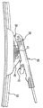
도 21은, 리벳을 갖는 장착 베이스를 구비하는, 와이퍼 블레이드를 예시한다.The following description and the annexed drawings set forth certain illustrative aspects of the invention. These aspects, however, represent only some of the various ways in which the principles of the invention can be used, and the invention is intended to include all such aspects and their equivalents. Other advantages and novel features of the present invention will become apparent from the following detailed description of the invention when considered in conjunction with the drawings.
1 is a perspective view of an embodiment of a wiper blade connector of the present disclosure;
FIG. 2 is a top plan view of the wiper blade connector of FIG. 1;
3 is a partial side view illustrating a range of motion of the partially rotatable door member relative to the first end of the wiper blade connector of FIG. 1;
3A is a side view of the first end of the wiper blade connector of FIG. 1, shown in cross-section, illustrating a partially rotatable door member;
3B is a side view of a partially rotatable door member;
4 is a perspective view of a single tongue wiper arm;
5 is a perspective view of a double tongue wiper arm;
6 is a side view of the wiper blade connector of FIG. 1 illustrating the rotational motion of a single tongue wiper arm for attachment to the wiper blade connector;
7 is a side view of the wiper blade connector of FIG. 1 illustrating the rotational movement of the double tongue wiper arm for attachment with the wiper blade connector;
FIG. 8 is a side view of the wiper blade connector of FIG. 1, locked onto a single tongue wiper arm;
9 is a side view of a wiper blade assembly, illustrating the approach of a single tongue wiper arm pair and a wiper blade connector for securing to a wiper blade;
10 is a side view of the wiper blade assembly, illustrating the wiper blade connector of FIG. 1 securing the wiper blade to a single tongue wiper arm;
11 is a perspective view of an embodiment of a wiper blade connector according to the present disclosure, with the cap in the “open” position;
12 is a first side view of the wiper blade connector of FIG. 11;
13 is a top view of the wiper blade connector of FIG. 11;
14 is a bottom view of the wiper blade connector of FIG. 11;
15 is a perspective view of the wiper blade connector of FIG. 11 with the cap removed;
16 is a perspective view of the cap of the wiper blade connector of FIG. 11;
FIG. 17 is a perspective view of the wiper blade connector of FIG. 11 with a wiper arm;
18 is a perspective view of the wiper blade connector of FIG. 11 with the cap in the “closed” position;
19 is a perspective view of an embodiment of the wiper blade connector of the present disclosure;
20 is a side view of the wiper blade connector embodiment of the wiper blade connector of FIG. 19; And
Figure 21 illustrates a wiper blade, with a mounting base with rivets.
본 개시 전체에 걸쳐, 용어 "부정관사"는 하나 또는 하나 초과를 지칭할 수 있을 것이다. 본 명세서에서, 용어 "또는"은, 달리 지시되지 않는 한, 비 배타적인 "또는"을 지칭하기 위해 사용된다. 더불어, "하나의 실시예"에 대한 참조는, 또한 인용되는 특징들을 통합하는, 부가적인 실시예들의 존재를 배제하는 것으로 해석되도록 의도되지 않는다. 나아가, 명시적으로 반대로 진술되지 않는 한, 특별한 특성을 갖는 요소 또는 복수의 요소를 "포함하는", "구비하는", 또는 "갖는" 실시예들은, 그러한 특성을 갖지 않는 부가적인 그러한 요소들을 포함할 수 있을 것이다.Throughout this disclosure, the term “indefinite article” may refer to one or more than one. In this specification, the term “or” is used to refer to a non-exclusive “or”, unless indicated otherwise. In addition, reference to “one embodiment” is not intended to be interpreted as excluding the existence of additional embodiments, which also incorporate the features cited. Furthermore, unless expressly stated to the contrary, embodiments that “comprise,” “have,” or “have” an element or a plurality of elements with special characteristics include additional such elements that do not have such characteristics. You will be able to.
뒤따르는 상세한 설명 및 첨부 도면들은, 단지 관련 분야의 당업자가 본 발명을 이루고 사용하는 것을 가능하게 할 목적으로, 본 개시의 예시적 실시예들을 설명하고 예시한다. 그에 따라, 이러한 실시예들에 대한 상세한 설명 및 도시는, 순수하게 본질적으로 예시이며 그리고, 어떤 식으로든, 본 발명의 범위 또는 본 발명의 보호를 임의의 방식으로 제한하고자 하는 것이 아니다. 도면들은 축적에 맞지 않을 수 있으며 그리고 어떤 경우에, 제작 및 조립에 대한 통상적인 세부사항과 같은 본 발명에 대한 이해를 위해 필요하지 않은, 세부사항이 생략되었을 수 있다는 것을, 또한 이해해야만 할 것이다. 또한 여기에서 "예들"로서 지칭되는, 이러한 실시예들은, 당업자가 본 명세서에 개시되는 대상을 실행하는 것을 가능하게 하기 위해 충분히 상세하게 설명된다. 실시예들이 조합될 수 있거나 또는 다른 실시예들이 활용될 수 있다는 것, 그리고 구조적, 논리적 그리고 전기적 변화들이, 본 명세서에 개시되는 대상의 범위로부터 벗어남 없이, 이루어질 수 있다는 것이, 이해되어야 한다. 뒤따르는 상세한 설명은, 따라서, 제한하는 의미로 취해지지 않아야 하며, 그리고 본 명세서에 개시되는 대상의 범위는, 첨부 청구항들 및 그들의 균등물들에 의해 한정된다.DETAILED DESCRIPTION The accompanying description and accompanying drawings describe and illustrate exemplary embodiments of the present disclosure, with the sole purpose of enabling those skilled in the relevant arts to make and use the invention. Accordingly, the detailed description and illustration of these embodiments is purely illustrative in nature and is not intended in any way to limit the scope of the invention or protection of the invention in any way. It should also be understood that the drawings may not be suitable for accumulation and, in some cases, details may be omitted, which are not necessary for an understanding of the present invention, such as typical details for fabrication and assembly. These embodiments, also referred to herein as “examples”, are described in sufficient detail to enable those skilled in the art to implement the subject matter disclosed herein. It should be understood that the embodiments can be combined or other embodiments can be utilized and that structural, logical and electrical changes can be made without departing from the scope of the subject matter disclosed herein. The detailed description that follows, therefore, should not be taken in a limiting sense, and the scope of the subject matter disclosed herein is defined by the appended claims and their equivalents.
와이퍼 블레이드를 와이퍼 아암에 연결하기 위한 와이퍼 블레이드 커넥터의 하나의 실시예가, 뒤따르는 구성요소들을 포함할 수 있을 것이다: 전방 단부, 후방 단부, 제1 측벽, 제2 측벽, 및 제1 측벽과 제2 측벽 사이에서 연장되는 상측 표면을 구비하는, 세장형 몸체 부재; 상기 제1 측벽과 상기 제2 측벽 사이에서 연장되는 아치형 리벳 클립으로서, 상기 아치형 리벳 클립은 와이퍼 블레이드를 상기 커넥터에 해제 가능하게 고정하도록 구성되고 배치되며, 그리고 상기 아치형 리벳 클립은 상기 와이퍼 블레이드의 작동 도중에 상기 해제 가능하게 고정된 와이퍼 블레이드가 선회하는 것을 허용하도록 크기결정되는 것인, 아치형 리벳 클립; 상기 제1 측벽과 상기 제2 측벽 사이에서 연장되는 리벳 통로로서, 상기 아치형 리벳 클립에 대한 노출된 접근을 제공하도록 구성되고 배치되는 것인, 리벳 통로; 상기 세장형 몸체 부재의 전방 단부를 향해 위치되는 제1 텅 수용 개구로서, 상기 제1 텅 수용 개구는, 와이퍼 아암의 대응하는 전방 텅을 수용하도록 구성되고 배치되어, 그로 인해 상기 와이퍼 아암이, 상기 와이퍼 아암의 상기 전방 텅이 상기 제1 텅 수용 개구 내에 수용될 때, 상기 상측 표면과 접촉하도록 하는 것인, 제1 텅 수용 개구; 상기 커넥터를 상기 와이퍼 아암에 해제 가능하게 잠금고정할 수 있는 잠금고정 메커니즘으로서, 잠금고정 메커니즘은 축을 중심으로 회전 가능한 도어 부재를 포함하고, 상기 축은, 상기 축의 모든 측면이 상기 도어 부재의 적어도 일부에 의해 둘러싸이도록, 상기 도어 부재 내부에 위치되며, 상기 도어 부재는 개방된 잠금고정 해제 위치와 폐쇄된 잠금고정 위치 사이에서 회전하도록 작동 가능하고, 상기 축을 둘러싸는 상기 도어 부재의 전체 부분은 상기 축을 중심으로 회전 가능하며, 상기 개방된 잠금고정 해제 위치는 상기 제1 텅 수용 개구에 대한 접근을 제공하는 역할을 하며, 그리고 상기 폐쇄된 잠금고정 위치는 상기 대응하는 전방 텅을 상기 제1 텅 수용 개구 내부에 해제 가능하게 잠금고정하는 역할을 하는 것인, 잠금고정 메커니즘; 및 상기 세장형 몸체 부재의 후방 단부를 향해 위치되는 제2 텅 수용 개구로서, 와이퍼 아암 상의 대응하는 후방 텅을 수용하도록 구성되고 배치되는 것인, 제2 텅 수용 개구.One embodiment of the wiper blade connector for connecting the wiper blade to the wiper arm may include the following components: front end, rear end, first sidewall, second sidewall, and first sidewall and second An elongated body member having an upper surface extending between side walls; An arched rivet clip extending between the first sidewall and the second sidewall, wherein the arched rivet clip is constructed and arranged to releasably secure the wiper blade to the connector, and the arched rivet clip operates the wiper blade An arched rivet clip that is sized to allow the releasably secured wiper blade to pivot along the way; A rivet passageway extending between the first sidewall and the second sidewall, wherein the rivet passageway is constructed and arranged to provide exposed access to the arched rivet clip; A first tongue receiving opening positioned toward the front end of the elongated body member, the first tongue receiving opening being constructed and arranged to receive a corresponding front tongue of the wiper arm, whereby the wiper arm is A first tongue receiving opening, when the front tongue of the wiper arm is brought into contact with the upper surface when received in the first tongue receiving opening; A locking mechanism capable of releasably locking the connector to the wiper arm, wherein the locking mechanism includes a door member rotatable about an axis, wherein the shaft is configured such that all sides of the axis are at least part of the door member. Surrounded by the door member, the door member is operable to rotate between an open unlocked position and a closed lock position, and the entire portion of the door member surrounding the axis is centered on the axis Rotatable, and the open unlocking position serves to provide access to the first tongue receiving opening, and the closed locking position positions the corresponding front tongue inside the first tongue receiving opening Locking mechanism that serves to release the lock to releasably; And a second tongue receiving opening positioned toward the rear end of the elongated body member, configured and arranged to receive a corresponding rear tongue on the wiper arm.
커넥터의 일부 실시예에서, 부분적으로 회전 가능한 도어 부재는, 사용자가 부분적으로 회전 가능한 도어 부재를 상기 개방된 잠금고정 해제 위치와 상기 폐쇄된 잠금고정 위치 사이에서 선회시키는 것을 그로 인해 허용하는, 사용자에 의한 파지를 위해 크기결정되는 벌어지는 후드(flared hood)를 더 구비할 수 있을 것이다. 상기 세장형 몸체 부재의 후방 단부는, 제1 측벽과 제2 측벽 각각을 따라 연장되는 쇼울더부를 구비할 수 있으며, 상기 쇼울더부는, 와이퍼 아암 상의 대응하는 날개 부재들과 해제 가능하게 맞물리도록 구성되고 배치된다. 상기 세장형 몸체 부재의 전방 단부는, 제1 측벽과 제2 측벽 각각을 따라 연장되는 경사부를 더 구비할 수 있으며, 상기 경사부는, 와이퍼 아암의 제1 텅을 제1 텅 수용 개구 내로 가이드하도록 구성되고 배치된다. 상기 아치형 리벳 클립은, 상기 커넥터에 대한 와이퍼 블레이드의 스냅결합식 부착을 그로 인해 허용하도록, 상기 리벳 통로보다 더 큰 직경을 구비할 수 있을 것이다. 상기 상측 표면은, 전방 단부와 후방 단부 사이에서 상기 세장형 몸체 부재의 대부분의 길이를 따라, 종방향으로 연장될 수 있을 것이다. 상기 잠금고정 메커니즘은 한 쌍의 잠금고정 벽을 더 구비할 수 있고, 회전 가능한 도어는 잠금고정 벽 쌍 사이에 수용되며, 그리고 상기 축은 상기 잠금고정 벽들 사이에서 연장된다.In some embodiments of the connector, the partially rotatable door member allows the user to thereby pivot the partially rotatable door member between the open unlocked position and the closed lock position. It may be further provided with a flared hood that is sized for gripping. The rear end of the elongated body member may have a shoulder portion extending along each of the first sidewall and the second sidewall, and the shoulder portion is configured and arranged to releasably engage corresponding wing members on the wiper arm do. The front end of the elongated body member may further include an inclined portion extending along each of the first sidewall and the second sidewall, wherein the inclined portion is configured to guide the first tongue of the wiper arm into the first tongue receiving opening. And placed. The arched rivet clip may be provided with a larger diameter than the rivet passageway, thereby allowing snap-on attachment of the wiper blade to the connector. The upper surface may extend longitudinally along most of the length of the elongated body member between the front end and the rear end. The locking mechanism may further include a pair of locking walls, a rotatable door is accommodated between the pair of locking walls, and the shaft extends between the locking walls.
와이퍼 블레이드를 와이퍼 아암에 연결하기 위한 커넥터의 다른 실시예에서, 커넥터는, 뒤따르는 구성요소들을 포함할 수 있을 것이다: 전방 단부, 후방 단부, 제1 측벽, 제2 측벽, 및 제1 측벽과 제2 측벽 사이에서 연장되는 상측 표면을 구비하는, 세장형 몸체 부재; 아치형 리벳 클립을 구비하는 커넥터 고정 구조물; 상기 제1 측벽과 상기 제2 측벽 사이에서 연장되는 리벳 통로로서, 상기 리벳 통로는 상기 아치형 리벳 클립에 대한 노출된 접근을 제공하도록 구성되고 배치되며, 그리고 상기 리벳 통로는, 상기 커넥터에 대한 상기 와이퍼 블레이드의 스냅결합식 부착을 그로 인해 허용하도록, 상기 아치형 리벳 클립의 직경보다 더 작게 크기결정되는 것인, 리벳 통로; 상기 세장형 몸체 부재의 전방 단부 상에 위치되는 제1 텅 수용 개구로서, 와이퍼 아암 상의 대응하는 전방 텅을 수용하도록 구성되고 배치되는 것인, 제1 텅 수용 개구; 상기 세장형 몸체 부재의 후방 단부를 향해 위치되는 제2 텅 수용 개구로서, 상기 제2 텅 수용 개구는 상기 상측 표면 내의 개구로서 구성되고, 와이퍼 아암 상의 대응하는 후방 텅이, 후방 텅의 적어도 일부분이 그로 인해 상기 상측 표면 아래에 위치설정되도록, 상기 제2 텅 수용 개구를 통해 삽입 가능하며, 그로 인해 상기 와이퍼 아암은, 상기 와이퍼 아암의 상기 전방 텅이 상기 제1 텅 수용 개구 내에 수용되며 그리고 상기 와이퍼 아암의 상기 제2 텅이 상기 제2 텅 수용 개구 내에 수용될 때, 상기 상측 표면과 접촉하는 것인, 제2 텅 수용 개구; 상기 커넥터를 상기 와이퍼 아암에 해제 가능하게 잠금고정할 수 있는 잠금고정 메커니즘으로서, 잠금고정 메커니즘은 축을 중심으로 회전 가능한 도어 부재를 포함하고, 상기 축은, 상기 축의 모든 측면이 상기 도어 부재의 적어도 일부에 의해 둘러싸이도록, 상기 도어 부재 내부에 위치되며, 상기 축을 둘러싸는 상기 도어 부재의 전체 부분은 상기 축을 중심으로 회전 가능하며, 상기 도어 부재는 개방된 잠금고정 해제 위치와 폐쇄된 잠금고정 위치 사이에서 회전하도록 작동 가능한 것인, 잠금고정 메커니즘; 및 상기 제2 텅 수용 개구 내에 수용될 때 상기 와이퍼 아암의 대응하는 후방 텅을 고정하는 것을 가능하게 하기 위해, 상기 제2 텅 수용 개구 내로 돌출하는 탭. In another embodiment of the connector for connecting the wiper blade to the wiper arm, the connector may include the following components: front end, rear end, first sidewall, second sidewall, and first sidewall and first An elongated body member having an upper surface extending between the two side walls; A connector fixing structure having an arcuate rivet clip; A rivet passage extending between the first sidewall and the second sidewall, wherein the rivet passage is configured and arranged to provide exposed access to the arcuate rivet clip, and the rivet passage, the wiper for the connector A rivet passage sized to be smaller than the diameter of the arched rivet clip, thereby allowing snap-on attachment of the blade; A first tongue receiving opening located on the front end of the elongated body member, the first tongue receiving opening being constructed and arranged to receive a corresponding front tongue on the wiper arm; A second tongue receiving opening positioned towards the rear end of the elongated body member, the second tongue receiving opening configured as an opening in the upper surface, a corresponding rear tongue on the wiper arm, at least a portion of the rear tongue It is possible to insert through the second tongue receiving opening so that it is positioned below the upper surface, whereby the wiper arm is such that the front tongue of the wiper arm is received within the first tongue receiving opening and the wiper A second tongue receiving opening, when the second tongue of the arm is in contact with the upper surface when received in the second tongue receiving opening; A locking mechanism capable of releasably locking the connector to the wiper arm, wherein the locking mechanism includes a door member that is rotatable about an axis, and wherein the shaft has all sides of the axis at least part of the door member. Enclosed by the door member, the entire portion of the door member surrounding the shaft is rotatable about the axis, and the door member rotates between an open unlocked position and a closed lock position. Locking mechanism, which is operable to; And a tab protruding into the second tongue receiving opening, to enable securing the corresponding rear tongue of the wiper arm when received within the second tongue receiving opening.
커넥터의 일부 실시예에서, 도어 부재는, 사용자가 부분적으로 회전 가능한 도어 부재를 상기 개방된 잠금고정 해제 위치와 상기 폐쇄된 잠금고정 위치 사이에서 선회시키는 것을 그로 인해 허용하는, 사용자에 의한 파지를 위해 크기결정되는 벌어지는 후드를 더 구비할 수 있을 것이다. 상기 세장형 몸체 부재의 전방 단부는, 제1 측벽과 제2 측벽 각각을 따라 연장되는 경사부를 더 구비할 수 있으며, 상기 경사부는, 와이퍼 아암의 제1 텅을 제1 텅 수용 개구 내로 가이드하도록 구성되고 배치된다. 상기 상측 표면은, 전방 단부와 후방 단부 사이에서 상기 세장형 몸체 부재의 대부분의 길이를 따라, 종방향으로 연장될 수 있을 것이다. 상기 잠금고정 메커니즘은 한 쌍의 잠금고정 벽을 더 구비할 수 있고, 회전 가능한 도어는 잠금고정 벽 쌍 사이에 수용되며, 그리고 상기 축은 상기 잠금고정 벽들 사이에서 연장된다.In some embodiments of the connector, the door member is for gripping by the user, thereby allowing the user to pivot the partially rotatable door member between the open unlocked position and the closed lock position. It may further include a flared hood that is sized. The front end of the elongated body member may further include an inclined portion extending along each of the first sidewall and the second sidewall, wherein the inclined portion is configured to guide the first tongue of the wiper arm into the first tongue receiving opening. And placed. The upper surface may extend longitudinally along most of the length of the elongated body member between the front end and the rear end. The locking mechanism may further include a pair of locking walls, a rotatable door is accommodated between the pair of locking walls, and the shaft extends between the locking walls.
와이퍼 조립체의 실시예가, 장착 베이스를 구비하는 와이퍼 블레이드, 및 와이퍼 블레이드를 와이퍼 아암에 연결하기 위한 커넥터를 포함할 수 있을 것이다. 커넥터는, 전방 단부, 후방 단부, 제1 측벽, 제2 측벽, 및 제1 측벽과 제2 측벽 사이에서 연장되는 상측 표면을 구비하는, 세장형 몸체 부재; 상기 제1 측벽과 상기 제2 측벽 사이에서 연장되는 아치형 리벳 클립으로서, 상기 아치형 리벳 클립은 와이퍼 블레이드를 상기 커넥터에 해제 가능하게 고정하도록 구성되고 배치되며, 그리고 상기 아치형 리벳 클립은 상기 와이퍼 블레이드의 작동 도중에 상기 해제 가능하게 고정된 와이퍼 블레이드가 선회하는 것을 허용하도록 크기결정되는 것인, 아치형 리벳 클립; 상기 제1 측벽과 상기 제2 측벽 사이에서 연장되는 리벳 통로로서, 상기 아치형 리벳 클립에 대한 노출된 접근을 제공하도록 구성되고 배치되는 것인, 리벳 통로; 상기 세장형 몸체 부재의 전방 단부를 향해 위치되는 제1 텅 수용 개구로서, 상기 제1 텅 수용 개구는, 와이퍼 아암의 대응하는 전방 텅을 수용하도록 구성되고 배치되어, 그로 인해 상기 와이퍼 아암이, 상기 와이퍼 아암의 상기 전방 텅이 상기 제1 텅 수용 개구 내에 수용될 때, 상기 상측 표면과 접촉하도록 하는 것인, 제1 텅 수용 개구; 상기 커넥터를 상기 와이퍼 아암에 해제 가능하게 잠금고정할 수 있는 잠금고정 메커니즘으로서, 잠금고정 메커니즘은 축을 중심으로 회전 가능한 도어 부재를 포함하고, 상기 축은, 상기 축의 모든 측면이 상기 도어 부재의 적어도 일부에 의해 둘러싸이도록, 상기 도어 부재 내부에 위치되며, 상기 도어 부재는 개방된 잠금고정 해제 위치와 폐쇄된 잠금고정 위치 사이에서 회전하도록 작동 가능하고, 상기 축을 둘러싸는 상기 도어 부재의 전체 부분은 상기 축을 중심으로 회전 가능하며, 상기 개방된 잠금고정 해제 위치는 상기 제1 텅 수용 개구에 대한 접근을 제공하는 역할을 하며, 그리고 상기 폐쇄된 잠금고정 위치는 상기 대응하는 전방 텅을 상기 제1 텅 수용 개구 내부에 해제 가능하게 잠금고정하는 역할을 하는 것인, 잠금고정 메커니즘; 및 상기 세장형 몸체 부재의 후방 단부를 향해 위치되는 제2 텅 수용 개구로서, 와이퍼 아암 상의 대응하는 후방 텅을 수용하도록 구성되고 배치되는 것인, 제2 텅 수용 개구를 포함할 수 있을 것이다. Embodiments of the wiper assembly may include a wiper blade having a mounting base, and a connector for connecting the wiper blade to the wiper arm. The connector includes an elongated body member having a front end, a rear end, a first side wall, a second side wall, and an upper surface extending between the first side wall and the second side wall; An arched rivet clip extending between the first sidewall and the second sidewall, wherein the arched rivet clip is constructed and arranged to releasably secure the wiper blade to the connector, and the arched rivet clip operates the wiper blade An arched rivet clip that is sized to allow the releasably secured wiper blade to pivot along the way; A rivet passageway extending between the first sidewall and the second sidewall, wherein the rivet passageway is constructed and arranged to provide exposed access to the arched rivet clip; A first tongue receiving opening positioned toward the front end of the elongated body member, the first tongue receiving opening being constructed and arranged to receive a corresponding front tongue of the wiper arm, whereby the wiper arm is A first tongue receiving opening, when the front tongue of the wiper arm is brought into contact with the upper surface when received in the first tongue receiving opening; A locking mechanism capable of releasably locking the connector to the wiper arm, wherein the locking mechanism includes a door member that is rotatable about an axis, and wherein the shaft has all sides of the axis at least part of the door member. Surrounded by the door member, the door member is operable to rotate between an open unlocked position and a closed lock position, and the entire portion of the door member surrounding the axis is centered on the axis Rotatable, and the open unlocking position serves to provide access to the first tongue receiving opening, and the closed locking position positions the corresponding front tongue inside the first tongue receiving opening Locking mechanism that serves to release the lock to releasably; And a second tongue receiving opening positioned towards the rear end of the elongated body member, the second tongue receiving opening being configured and arranged to receive a corresponding rear tongue on the wiper arm.
와이퍼 블레이드를 와이퍼 아암에 연결하기 위한 커넥터의 다른 실시예에서, 커넥터는, 전방 단부, 후방 단부, 제1 측벽, 제2 측벽, 및 제1 측벽과 제2 측벽 사이에서 연장되는 상측 표면을 구비하는, 세장형 몸체 부재; 커넥터 고정 구조물; 상기 세장형 몸체 부재의 전방 단부를 향해 위치되는 제1 텅 수용 개구로서, 와이퍼 아암의 대응하는 전방 텅을 수용하도록 구성되는 것인, 제1 텅 수용 개구; 상기 커넥터의 전방 단부 근처에 제공되는 캡으로서, 상기 캡은 개방 위치와 폐쇄 위치 사이에서 슬라이딩 가능하고, 상기 캡은 와이퍼 아암 상의 수용되는 대응하는 전방 텅을 고정하도록 작동 가능한 것인, 캡을 포함할 수 있을 것이다. 커넥터는, 상기 세장형 몸체 부재의 제1 단부 근처에서 상기 제1 측벽의 일부분을 따라 종방향으로 연장되는 측방 채널; 및 상기 캡의 내측 표면 상에 제공되는 측방 인덴트(side indent)로서, 상기 측방 인덴트는, 상기 캡이 개방 위치와 폐쇄 위치 사이에서 슬라이딩될 때, 상기 제1 측벽을 따라 슬라이딩하도록 상응하게 치수결정되고 위치설정되는 것인, 측방 인덴트를 더 구비할 수 있을 것이다. 커넥터는, 상기 세장형 몸체 부재의 제1 단부 근처에서 상기 제2 측벽의 일부분을 따라 종방향으로 연장되는 제2 측방 채널; 및 상기 캡의 대향하는 내측 표면 상에 제공되는 부가적 측방 인덴트로서, 상기 부가적 측방 인덴트는, 상기 캡이 개방 위치와 폐쇄 위치 사이에서 슬라이딩될 때, 상기 제2 측벽을 따라 슬라이딩하도록 상응하게 치수결정되고 위치설정되는 것인, 부가적 측방 인덴트를 더 구비할 수 있을 것이다. 커넥터는, 상기 제1 텅 개구 내부에 제공되는 전방 잠금고정 탭으로서, 상측 부분 및, 상측 부분을 상기 세장형 몸체 부재와 연결하는, 아암 부분을 구비하는 것인, 전방 잠금고정 탭; 상기 캡의 하측 표면 상에 제공되는 잠금고정 탭 채널로서, 상기 잠금고정 탭 채널은, 상기 캡이 개방 위치와 폐쇄 위치 사이에서 슬라이딩될 때, 상기 전방 잠금고정 탭의 상기 상측 부분이 상기 잠금고정 탭 채널을 따라 슬라이딩하는 것을 허용하도록 합치하게 치수결정되는 것인, 잠금고정 탭 채널을 더 구비할 수 있을 것이다. 커넥터는, 상기 잠금고정 탭 채널에 인접하게 상기 캡 상에 제공되는 잠금고정 탭 캐비티로서, 상기 잠금고정 탭의 상기 상측 부분과 합치하게 치수결정되며 그리고 상기 캡이 폐쇄 위치에 놓일 때 상기 잠금고정 탭의 상기 상측 부분을 수용하도록 위치설정되는 것인, 잠금고정 탭 캐비티를 더 구비할 수 있을 것이다. 일부 실시예에서, 상기 캡의 탄력적 부분이, 상기 캐비티의 안팎으로 상기 잠금고정 탭의 상기 상측 부분을 슬라이딩시키기 위해 요구되는 종방향 힘을 증가시키기 위해, 상기 잠금고정 탭 채널 내로 돌출한다. 커넥터는, 상기 캡의 하측 표면으로부터 돌출하는 상측 탭으로서, 상기 세장형 몸체 부재의 상측 표면과 접촉하는 것인, 상측 탭을 더 구비할 수 있을 것이다. 일부 실시예에서, 상기 상측 탭이 하측 표면으로부터 돌출하는 거리는, 상기 세장형 몸체 부재의 상기 상측 표면과 상기 캡 사이의 틈새 거리이고, 상기 틈새 거리는, 상기 캡이 폐쇄 위치로 슬라이딩될 때, 상기 캡이 상기 수용되는 전방 텅의 원위 부분 위로 슬라이딩하는 것을 허용하기에 충분하다. 일부 실시예에서, 커넥터 고정 구조물은, 리벳 통로 및 아치형 리벳 클립을 구비하고, 상기 아치형 리벳 클립은, 제1 측벽과 제2 측벽 사이에서 연장되며 그리고 와이퍼 블레이드를 커넥터에 해제 가능하게 고정하도록 구성되고 배치되며, 그리고 상기 아치형 리벳 클립은, 와이퍼 블레이드의 작동 도중에 상기 해제 가능하게 고정되는 와이퍼 블레이드가 선회하는 것을 허용하도록 크기결정되며; 그리고 상기 리벳 통로는, 제1 측벽과 제2 측벽 사이에서 연장되며, 상기 리벳 통로는, 상기 아치형 리벳 클립에 대한 접근을 허용하도록 구성되고 배치된다.In another embodiment of the connector for connecting the wiper blade to the wiper arm, the connector includes a front end, a rear end, a first side wall, a second side wall, and an upper surface extending between the first side wall and the second side wall. , Elongated body member; Connector fixing structures; A first tongue receiving opening positioned towards the front end of the elongated body member, the first tongue receiving opening being configured to receive a corresponding front tongue of the wiper arm; A cap provided near the front end of the connector, wherein the cap is slidable between an open position and a closed position, and the cap is operable to secure a corresponding corresponding front tongue on the wiper arm. Will be able to. The connector comprises: a lateral channel extending longitudinally along a portion of the first sidewall near the first end of the elongated body member; And a side indent provided on the inner surface of the cap, the side indent correspondingly dimensioned to slide along the first sidewall when the cap is sliding between the open and closed positions. Determined and positioned, it may be further provided with a lateral indentation. The connector includes: a second lateral channel extending longitudinally along a portion of the second sidewall near the first end of the elongated body member; And an additional lateral indent provided on the opposite inner surface of the cap, wherein the additional lateral indent corresponds to slide along the second sidewall when the cap slides between an open position and a closed position. It may be further provided with additional lateral indents, which are dimensionally sized and positioned. The connector comprises: a front lock fixing tab provided inside the first tongue opening, the front lock fixing tab having an upper portion and an arm portion connecting the upper portion with the elongated body member; A locking tab channel provided on the lower surface of the cap, wherein the locking tab channel is such that when the cap is sliding between an open position and a closed position, the upper portion of the front locking tab is the locking tab. It may further be provided with a locking tab channel, which is sized reasonably to allow sliding along the channel. A connector is a locking tab cavity provided on the cap adjacent to the locking tab channel, dimensioned to fit the upper portion of the locking tab and the locking tab when the cap is in the closed position It is positioned to accommodate the upper portion of the, it may be further provided with a lock tab tab cavity. In some embodiments, the elastic portion of the cap protrudes into the locking tab channel to increase the longitudinal force required to slide the upper portion of the locking tab in and out of the cavity. The connector may further include an upper tab, which is an upper tab protruding from the lower surface of the cap, which is in contact with the upper surface of the elongated body member. In some embodiments, the distance at which the upper tab protrudes from the lower surface is a clearance distance between the upper surface of the elongate body member and the cap, and the clearance distance is the cap when the cap is slid to the closed position. This is sufficient to allow sliding over the distal portion of the receiving front tongue. In some embodiments, the connector securing structure is provided with a rivet passageway and an arcuate rivet clip, the arcuate rivet clip being configured to extend between the first sidewall and the second sidewall and releasably secure the wiper blade to the connector. Disposed, and the arched rivet clip is sized to allow the releasably secured wiper blade to pivot during operation of the wiper blade; And the rivet passage extends between the first sidewall and the second sidewall, and the rivet passage is constructed and arranged to allow access to the arched rivet clip.
본 개시의 다른 실시예에서, 와이퍼 블레이드를 와이퍼 아암에 연결하기 위한 커넥터가, 전방 단부, 후방 단부, 제1 측벽, 제2 측벽, 및 제1 측벽과 제2 측벽 사이에서 연장되는 상측 표면을 구비하는, 세장형 몸체 부재; 커넥터 고정 구조물; 상기 세장형 몸체 부재의 전방 단부를 향해 위치되는 제1 텅 수용 개구로서, 와이퍼 아암의 대응하는 전방 텅을 수용하도록 구성되는 것인, 제1 텅 수용 개구; 상기 세장형 몸체 부재의 후방 단부를 향해 위치되는 제2 텅 수용 개구로서, 와이퍼 아암의 대응하는 전방 텅을 수용하도록 구성되는 것인, 제2 텅 수용 개구; 및 상기 커넥터의 전방 단부 근처에 제공되는 캡으로서, 상기 캡은 개방 위치와 폐쇄 위치 사이에서 슬라이딩 가능하고, 상기 캡은 와이퍼 아암 상의 수용되는 대응하는 전방 텅을 고정하도록 작동 가능한 것인, 캡을 포함할 수 있을 것이다. 커넥터는, 후방 텅 개구 내로 돌출하는 후방 탭을 더 구비할 수 있고, 적어도 후방 텅의 원위 부분이, 제2 텅 개구 내에 수용될 때, 후방 탭 아래에 끼워질 수 있다. 커넥터는, 상기 세장형 몸체 부재의 제1 단부 근처에서 상기 제1 측벽의 일부분을 따라 종방향으로 연장되는 측방 채널; 상기 캡의 내측 표면 상에 제공되는 측방 인덴트로서, 상기 측방 인덴트는, 상기 캡이 개방 위치와 폐쇄 위치 사이에서 슬라이딩될 때, 상기 제1 측벽을 따라 슬라이딩하도록 상응하게 치수결정되고 위치설정되는 것인, 측방 인덴트; 상기 세장형 몸체 부재의 제1 단부 근처에서 상기 제2 측벽의 일부분을 따라 종방향으로 연장되는 제2 측방 채널; 상기 캡의 대향하는 내측 표면 상에 제공되는 부가적 측방 인덴트로서, 상기 부가적 측방 인덴트는, 상기 캡이 개방 위치와 폐쇄 위치 사이에서 슬라이딩될 때, 상기 제2 측벽을 따라 슬라이딩하도록 상응하게 치수결정되고 위치설정되는 것인, 부가적 측방 인덴트; 상기 제1 텅 개구 내부에 제공되는 전방 잠금고정 탭으로서, 상측 부분 및, 상측 부분을 상기 세장형 몸체 부재와 연결하는, 아암 부분을 구비하는 것인, 전방 잠금고정 탭; 상기 캡의 하측 표면 상에 제공되는 잠금고정 탭 채널로서, 상기 잠금고정 탭 채널은, 상기 캡이 개방 위치와 폐쇄 위치 사이에서 슬라이딩될 때, 상기 전방 잠금고정 탭의 상기 상측 부분이 상기 잠금고정 탭 채널을 따라 슬라이딩하는 것을 허용하도록 합치하게 치수결정되는 것인, 잠금고정 탭 채널; 상기 잠금고정 탭 채널에 인접하게 상기 캡 상에 제공되는 잠금고정 탭 캐비티로서, 상기 캐비티는, 상기 잠금고정 탭의 상기 상측 부분과 합치하게 치수결정되며 그리고 상기 캡이 폐쇄 위치에 놓일 때 상기 잠금고정 탭의 상기 상측 부분을 수용하도록 위치설정되고, 상기 캡의 탄력적 부분이, 상기 캐비티의 안팎으로 상기 잠금고정 탭의 상기 상측 부분을 슬라이딩시키기 위해 요구되는 종방향 힘을 증가시키기 위해, 상기 잠금고정 탭 채널 내로 돌출하는 것인, 잠금고정 탭 캐비티; 및 상기 캡의 하측 표면으로부터 틈새 거리만큼 돌출하는 상측 탭으로서, 상기 상측 탭은 상기 세장형 몸체 부재의 상측 표면과 접촉하고, 상기 틈새 거리는, 상기 캡이 폐쇄 위치로 슬라이딩될 때, 상기 캡이 상기 수용되는 전방 텅의 원위 부분 위로 슬라이딩하는 것을 허용하기에 충분한 것인, 상측 탭을 더 포함할 수 있을 것이다.In another embodiment of the present disclosure, a connector for connecting the wiper blade to the wiper arm has a front end, a rear end, a first side wall, a second side wall, and an upper surface extending between the first side wall and the second side wall. The elongated body member; Connector fixing structures; A first tongue receiving opening positioned towards the front end of the elongated body member, the first tongue receiving opening being configured to receive a corresponding front tongue of the wiper arm; A second tongue receiving opening positioned towards the rear end of the elongated body member, the second tongue receiving opening being configured to receive a corresponding front tongue of the wiper arm; And a cap provided near the front end of the connector, wherein the cap is slidable between an open position and a closed position, and the cap is operable to secure a corresponding corresponding front tongue on the wiper arm. You will be able to. The connector may further include a rear tab projecting into the rear tongue opening, and at least when the distal portion of the rear tongue is received within the second tongue opening, it may fit under the rear tab. The connector comprises: a lateral channel extending longitudinally along a portion of the first sidewall near the first end of the elongated body member; As a lateral indent provided on the inner surface of the cap, the lateral indent is correspondingly dimensioned and positioned to slide along the first sidewall when the cap slides between an open position and a closed position. Will, lateral indentation; A second lateral channel extending longitudinally along a portion of the second sidewall near the first end of the elongated body member; As an additional lateral indent provided on the opposing inner surface of the cap, the additional lateral indent correspondingly slides along the second sidewall when the cap slides between an open position and a closed position. Additional lateral indents, which are dimensioned and positioned; A front locking and fixing tab provided inside the first tongue opening, the upper locking portion and an arm portion connecting the upper portion with the elongated body member; A locking tab channel provided on the lower surface of the cap, wherein the locking tab channel is such that when the cap is sliding between an open position and a closed position, the upper portion of the front locking tab is the locking tab. A locking tab channel, which is dimensionally sized to allow sliding along the channel; A locking tab cavity provided on the cap adjacent to the locking tab channel, the cavity being dimensioned to match the upper portion of the locking tab and locking the cap when the cap is in the closed position Positioned to receive the upper portion of the tab, and the elastic portion of the cap to increase the longitudinal force required to slide the upper portion of the locking tab in and out of the cavity, the locking tab A locking tab cavity, which protrudes into the channel; And an upper tab protruding by a clearance distance from the lower surface of the cap, wherein the upper tab contacts the upper surface of the elongated body member, and the clearance distance is such that when the cap is slid to the closed position, the cap is It may further include an upper tab, which is sufficient to allow sliding over the distal portion of the received front tongue.
와이퍼 블레이드 조립체의 실시예가 추가로, 본 개시에 따라 제공되고, 여기서 와이퍼 블레이드 조립체는, 와이퍼 스트립 및 장착 베이스를 포함하는 와이퍼 블레이드; 및 와이퍼 블레이드를 와이퍼 아암에 연결하기 위한 커넥터를 포함할 수 있으며, 상기 커넥터는, 전방 단부, 후방 단부, 제1 측벽, 제2 측벽, 및 제1 측벽과 제2 측벽 사이에서 연장되는 상측 표면을 구비하는, 세장형 몸체 부재; 커넥터 고정 구조물; 상기 세장형 몸체 부재의 전방 단부를 향해 위치되는 제1 텅 수용 개구로서, 와이퍼 아암의 대응하는 전방 텅을 수용하도록 구성되는 것인, 제1 텅 수용 개구; 및 상기 커넥터의 전방 단부 근처에 제공되는 캡으로서, 상기 캡은 개방 위치와 폐쇄 위치 사이에서 슬라이딩 가능하고, 상기 캡은 와이퍼 아암 상의 수용되는 대응하는 전방 텅을 고정하도록 작동 가능한 것인, 캡을 포함한다. 와이퍼 블레이드 조립체의 커넥터는, 상기 세장형 몸체 부재의 제1 단부 근처에서 상기 제1 측벽의 일부분을 따라 종방향으로 연장되는 측방 채널; 및 상기 캡의 내측 표면 상에 제공되는 측방 인덴트로서, 상기 측방 인덴트는, 상기 캡이 개방 위치와 폐쇄 위치 사이에서 슬라이딩될 때, 상기 제1 측벽을 따라 슬라이딩하도록 상응하게 치수결정되고 위치설정되는 것인, 측방 인덴트를 더 구비할 수 있을 것이다. 와이퍼 블레이드 조립체는, 상기 세장형 몸체 부재의 제1 단부 근처에서 상기 제2 측벽의 일부분을 따라 종방향으로 연장되는 제2 측방 채널; 및 상기 캡의 대향하는 내측 표면 상에 제공되는 부가적 측방 인덴트로서, 상기 부가적 측방 인덴트는, 상기 캡이 개방 위치와 폐쇄 위치 사이에서 슬라이딩될 때, 상기 제2 측벽을 따라 슬라이딩하도록 상응하게 치수결정되고 위치설정되는 것인, 부가적 측방 인덴트를 더 구비할 수 있을 것이다. 와이퍼 블레이드 조립체의 커넥터는, 상기 제1 텅 개구 내부에 제공되는 전방 잠금고정 탭으로서, 상측 부분 및, 상측 부분을 상기 세장형 몸체 부재와 연결하는, 아암 부분을 구비하는 것인, 전방 잠금고정 탭; 상기 캡의 하측 표면 상에 제공되는 잠금고정 탭 채널로서, 상기 잠금고정 탭 채널은, 상기 캡이 개방 위치와 폐쇄 위치 사이에서 슬라이딩될 때, 상기 전방 잠금고정 탭의 상기 상측 부분이 상기 잠금고정 탭 채널을 따라 슬라이딩하는 것을 허용하도록 합치하게 치수결정되는 것인, 잠금고정 탭 채널을 더 구비할 수 있을 것이다. 커넥터는, 상기 잠금고정 탭 채널에 인접하게 상기 캡 상에 제공되는 잠금고정 탭 캐비티로서, 상기 잠금고정 탭의 상기 상측 부분과 합치하게 치수결정되며 그리고 상기 캡이 폐쇄 위치에 놓일 때 상기 잠금고정 탭의 상기 상측 부분을 수용하도록 위치설정되는 것인, 잠금고정 탭 캐비티를 더 구비할 수 있을 것이다. 일부 실시예에서, 상기 캡의 탄력적 부분이, 상기 캐비티의 안팎으로 상기 잠금고정 탭의 상기 상측 부분을 슬라이딩시키기 위해 요구되는 종방향 힘을 증가시키기 위해, 상기 잠금고정 탭 채널 내로 돌출한다. 커넥터는, 상기 캡의 하측 표면으로부터 돌출하는 상측 탭으로서, 상기 세장형 몸체 부재의 상측 표면과 접촉하는 것인, 상측 탭을 더 구비할 수 있을 것이다. 일부 실시예에서, 상기 상측 탭이 하측 표면으로부터 돌출하는 거리는, 상기 세장형 몸체 부재의 상기 상측 표면과 상기 캡 사이의 틈새 거리이고, 상기 틈새 거리는, 상기 캡이 폐쇄 위치로 슬라이딩될 때, 상기 캡이 상기 수용되는 전방 텅의 원위 부분 위로 슬라이딩하는 것을 허용하기에 충분하다.An embodiment of a wiper blade assembly is further provided in accordance with the present disclosure, wherein the wiper blade assembly comprises: a wiper blade comprising a wiper strip and a mounting base; And a connector for connecting the wiper blade to the wiper arm, the connector comprising: a front end, a rear end, a first sidewall, a second sidewall, and an upper surface extending between the first sidewall and the second sidewall. Equipped, elongated body member; Connector fixing structures; A first tongue receiving opening positioned towards the front end of the elongated body member, the first tongue receiving opening being configured to receive a corresponding front tongue of the wiper arm; And a cap provided near the front end of the connector, wherein the cap is slidable between an open position and a closed position, and the cap is operable to secure a corresponding corresponding front tongue on the wiper arm. do. The connector of the wiper blade assembly includes: a lateral channel extending longitudinally along a portion of the first sidewall near the first end of the elongated body member; And a lateral indent provided on the inner surface of the cap, the lateral indent being correspondingly dimensioned and positioned to slide along the first sidewall when the cap is sliding between the open and closed positions. It will be, it may be further provided with a lateral indentation. The wiper blade assembly includes: a second lateral channel extending longitudinally along a portion of the second sidewall near the first end of the elongated body member; And an additional lateral indent provided on the opposite inner surface of the cap, wherein the additional lateral indent corresponds to slide along the second sidewall when the cap slides between an open position and a closed position. It may be further provided with additional lateral indents, which are dimensionally sized and positioned. The connector of the wiper blade assembly, as a front locking tab provided inside the first tongue opening, includes an upper portion and an arm portion connecting the upper portion with the elongated body member, the front locking fixing tab ; A locking tab channel provided on the lower surface of the cap, wherein the locking tab channel is such that when the cap is sliding between an open position and a closed position, the upper portion of the front locking tab is the locking tab. It may further be provided with a locking tab channel, which is sized reasonably to allow sliding along the channel. A connector is a locking tab cavity provided on the cap adjacent to the locking tab channel, dimensioned to fit the upper portion of the locking tab and the locking tab when the cap is in the closed position It is positioned to accommodate the upper portion of the, it may be further provided with a lock tab tab cavity. In some embodiments, the elastic portion of the cap protrudes into the lock tab channel to increase the longitudinal force required to slide the top portion of the lock tab into and out of the cavity. The connector may further include an upper tab, which is an upper tab protruding from the lower surface of the cap, which is in contact with the upper surface of the elongated body member. In some embodiments, the distance that the upper tab protrudes from the lower surface is a clearance distance between the upper surface of the elongate body member and the cap, and the clearance distance is the cap when the cap is slid to the closed position. This is sufficient to allow sliding over the distal portion of the receiving front tongue.
특정 실시예에서, 와이퍼 블레이드를 연결하기 위한 커넥터가, 본 개시에 따라 제공된다. 커넥터는, 제1 측벽, 제2 측벽, 및 제1 측벽과 제2 측벽 사이에서 연장되는 상측 표면을 구비하는, 몸체 부재를 포함할 수 있을 것이다. 커넥터는, 리벳 통로 및 아치형 리벳 클립을 포함하는 커넥터 고정 구조물로서, 아치형 리벳 클립은 리벳 통로에 대해 실질적으로 수직으로 연장되는 것인, 커넥터 고정 구조물을 더 포함할 수 있을 것이다.In certain embodiments, a connector for connecting a wiper blade is provided in accordance with the present disclosure. The connector may include a body member having a first sidewall, a second sidewall, and an upper surface extending between the first sidewall and the second sidewall. The connector may further include a connector fixing structure, wherein the connector fixing structure includes a rivet passage and an arcuate rivet clip, wherein the arcuate rivet clip extends substantially perpendicular to the rivet passage.
특정 실시예에서, 커넥터 고정 구조물은, 상기 제1 측벽 상에 구현된다. 특정의 그러한 실시예에서, 커넥터 고정 구조물은, 상기 제2 측벽 상에 구현된다. 특정 실시예에서, 아치형 리벳 클립은, 와이퍼 블레이드의 리벳을 고정할 수 있다. 특정 실시예에서, 아치형 리벳 클립은, 와이퍼 블레이드의 돌출부를 고정할 수 있다.In certain embodiments, a connector securing structure is implemented on the first sidewall. In certain such embodiments, a connector securing structure is implemented on the second sidewall. In certain embodiments, the arcuate rivet clip can secure the rivets of the wiper blade. In certain embodiments, the arched rivet clip can secure the protrusion of the wiper blade.
특정 실시예에서, 와이퍼 블레이드 조립체가 추가로, 본 개시에 따라 제공된다. 와이퍼 블레이드 조립체는, 와이퍼 스트립 및 장착 베이스를 포함하는, 와이퍼 블레이드; 및 와이퍼 블레이드를 와이퍼 아암에 연결하기 위한 커넥터를 포함할 수 있을 것이다. 커넥터는, 제1 측벽, 제2 측벽, 및 제1 측벽과 제2 측벽 사이에서 연장되는 상측 표면을 구비하는, 몸체 부재를 포함할 수 있을 것이다. 커넥터는, 리벳 통로 및 아치형 리벳 클립을 포함하는 커넥터 고정 구조물로서, 아치형 리벳 클립은 리벳 통로에 대해 실질적으로 수직으로 연장되는 것인, 커넥터 고정 구조물을 더 포함할 수 있을 것이다. In certain embodiments, wiper blade assemblies are further provided in accordance with the present disclosure. The wiper blade assembly includes a wiper blade, including a wiper strip and a mounting base; And a connector for connecting the wiper blade to the wiper arm. The connector may include a body member having a first sidewall, a second sidewall, and an upper surface extending between the first sidewall and the second sidewall. The connector may further include a connector fixing structure, wherein the connector fixing structure includes a rivet passage and an arcuate rivet clip, wherein the arcuate rivet clip extends substantially perpendicular to the rivet passage.
특정 실시예에서, 커넥터 고정 구조물은, 상기 제1 측벽 상에 구현된다. 특정의 그러한 실시예에서, 커넥터 고정 구조물은, 상기 제2 측벽 상에 구현된다. 특정 실시예에서, 장착 베이스는, 리벳을 더 포함하며, 그리고 아치형 리벳 클립은, 상기 리벳을 고정할 수 있다. 특정 실시예에서, 장착 베이스는, 적어도 하나의 돌출부를 더 포함하며, 그리고 아치형 리벳 클립은, 상기 적어도 하나의 돌출부를 고정할 수 있다.In certain embodiments, a connector securing structure is implemented on the first sidewall. In certain such embodiments, a connector securing structure is implemented on the second sidewall. In a particular embodiment, the mounting base further includes a rivet, and an arched rivet clip can secure the rivet. In certain embodiments, the mounting base further comprises at least one protrusion, and the arched rivet clip can secure the at least one protrusion.
특정 실시예에서, 와이퍼 블레이드를 와이퍼 아암과 커플링하기 위한 커넥터가, 본 개시에 따라 제공된다. 커넥터는, 전방 단부, 후방 단부, 제1 측벽, 제2 측벽, 및 제1 측벽과 제2 측벽 사이에서 연장되는 상측 표면을 구비하는, 세장형 몸체 부재; 커넥터 고정 구조물을 포함할 수 있을 것이다. 커넥터 고정 구조물은, 리벳 통로 및 아치형 리벳 클립을 포함할 수 있고, 아치형 리벳 클립은 리벳 통로에 대해 실질적으로 수직으로 연장된다. 커넥터는, 세장형 몸체 부재의 제1 단부 근처에서 제1 측벽의 외측 표면의 일부분을 따라 종방향으로 연장되는, 제1 측방 채널을 더 구비할 수 있을 것이다. 커넥터는, 세장형 몸체 부재의 전방 단부를 향해 위치되는 제1 텅 수용 개구를 더 구비할 수 있으며, 여기서 제1 텅 개구는, 와이퍼 아암 상의 대응하는 전방 텅을 수용하도록 구성될 수 있을 것이다. 캡은, 상측 벽 및 제1 측벽과 제2 측벽을 구비하며, 그리고 캡의 제1 측벽의 내부 표면 상에 제공되는 제1 측방 돌출부를 구비하는, U-자 형상 캡일 수 있을 것이다. 캡의 제1 측방 돌출부는, 캡이 와이퍼 아암 상의 수용되는 대응하는 전방 텅을 고정하기 위해 작동할 수 있도록, 캡이 개방 위치와 폐쇄 위치 사이에서 슬라이딩될 때, 제1 측방 채널을 따라 슬라이딩하도록 상응하게 치수결정되고 위치설정될 수 있을 것이다. 제1 측방 채널은, 세장형 몸체 부재의 종방향에 대응하는 방향으로 배향될 수 있고, 캡은 그로 인해 상측 표면에 실질적으로 평행하게 슬라이딩 가능하다.In certain embodiments, a connector for coupling a wiper blade with a wiper arm is provided in accordance with the present disclosure. The connector includes an elongated body member having a front end, a rear end, a first side wall, a second side wall, and an upper surface extending between the first side wall and the second side wall; It may include a connector fixing structure. The connector securing structure may include a rivet passageway and an arcuate rivet clip, the arcuate rivet clip extending substantially perpendicular to the rivet passageway. The connector may further include a first lateral channel extending longitudinally along a portion of the outer surface of the first sidewall near the first end of the elongated body member. The connector may further include a first tongue receiving opening positioned toward the front end of the elongated body member, wherein the first tongue opening may be configured to receive a corresponding front tongue on the wiper arm. The cap may be a U-shaped cap, having an upper wall and a first sidewall and a second sidewall, and a first lateral protrusion provided on the inner surface of the first sidewall of the cap. The first lateral protrusion of the cap corresponds to slide along the first lateral channel when the cap is sliding between the open and closed positions, so that the cap can act to secure the corresponding corresponding front tongue on the wiper arm Can be dimensioned and positioned. The first lateral channel can be oriented in a direction corresponding to the longitudinal direction of the elongated body member, and the cap is thereby slidable substantially parallel to the upper surface.
특정 실시예에서, 제2 측방 채널이, 상기 세장형 몸체 부재의 제1 단부 근처에서 상기 제2 측벽의 외측 표면의 일부분을 따라 종방향으로 연장되며; 그리고 부가적 측방 돌출부가, 상기 캡의 대향하는 내측 표면 상에 제공되고, 상기 부가적 측방 돌출부는, 상기 캡이 개방 위치와 폐쇄 위치 사이에서 슬라이딩될 때, 상기 제2 측방 채널을 따라 슬라이딩하도록 상응하게 치수결정되고 위치설정된다. 특정 실시예에서, 전방 잠금고정 탭이, 상기 제1 텅 개구 내부에 제공되고, 전방 잠금고정 탭은, 상측 부분 및, 상측 부분을 상기 세장형 몸체 부재와 연결하는, 아암 부분을 구비하고; 잠금고정 탭 채널이, 상기 캡의 하측 표면 상에 제공되고, 상기 잠금고정 탭 채널은, 상기 캡이 개방 위치와 폐쇄 위치 사이에서 슬라이딩될 때, 상기 전방 잠금고정 탭의 상기 상측 부분이 상기 잠금고정 탭 채널을 따라 슬라이딩하는 것을 허용하도록 합치하게 치수결정된다. 특정 실시예에서, 잠금고정 탭 캐비티가, 상기 잠금고정 탭 채널에 인접하게 상기 캡 상에 제공되고, 상기 캐비티는, 상기 잠금고정 탭의 상기 상측 부분과 합치하게 치수결정되며 그리고 상기 캡이 폐쇄 위치에 놓일 때 상기 잠금고정 탭의 상기 상측 부분을 수용하도록 위치설정된다. In a particular embodiment, a second lateral channel extends longitudinally along a portion of the outer surface of the second sidewall near the first end of the elongated body member; And an additional lateral protrusion is provided on the opposite inner surface of the cap, and the additional lateral protrusion corresponds to slide along the second lateral channel when the cap is sliding between the open and closed positions. Are dimensioned and positioned. In a specific embodiment, a front locking tab is provided inside the first tongue opening, the front locking tab has an upper portion and an arm portion connecting the upper portion with the elongated body member; A locking tab channel is provided on the lower surface of the cap, and the locking tab channel is such that when the cap is sliding between the open position and the closed position, the upper portion of the front locking tab is locked. It is dimensioned consistently to allow sliding along the tap channel. In a particular embodiment, a locking tab cavity is provided on the cap adjacent to the locking tab channel, the cavity is dimensioned to match the upper portion of the locking tab and the cap is in a closed position It is positioned to accommodate the upper portion of the locking tab when placed on.
특정 실시예에서, 상기 캡의 탄력적 부분이, 상기 캐비티의 안팎으로 상기 잠금고정 탭의 상기 상측 부분을 슬라이딩시키기 위해 요구되는 종방향 힘을 증가시키기 위해, 상기 잠금고정 탭 채널 내로 돌출한다. 특정 실시예에서, 상측 돌출부가, 상기 캡의 하측 표면으로부터 돌출하고, 상기 상측 돌출부는, 상기 세장형 몸체 부재의 상측 표면과 접촉한다. 특정 실시예에서, 상기 상측 돌출부가 하측 표면으로부터 돌출하는 거리는, 상기 세장형 몸체 부재의 상기 상측 표면과 상기 캡 사이의 틈새 거리이고, 상기 틈새 거리는, 상기 캡이 폐쇄 위치로 슬라이딩될 때, 상기 캡이 상기 수용되는 전방 텅의 원위 부분 위로 슬라이딩하는 것을 허용하기에 충분하다. 특정 실시예에서, 상기 아치형 리벳 클립은, 제1 측벽과 제2 측벽 사이에서 연장되며 그리고 와이퍼 블레이드를 커넥터에 해제 가능하게 고정하도록 구성되고 배치되며, 그리고 상기 아치형 리벳 클립은, 와이퍼 블레이드의 작동 도중에 상기 해제 가능하게 고정되는 와이퍼 블레이드가 선회하는 것을 허용하도록 크기결정되며; 그리고 상기 리벳 통로는, 제1 측벽과 제2 측벽 사이에서 연장되며, 상기 리벳 통로는, 상기 아치형 리벳 클립에 대한 접근을 허용하도록 구성되고 배치된다.In a specific embodiment, the elastic portion of the cap projects into the locking tab channel to increase the longitudinal force required to slide the upper portion of the locking tab in and out of the cavity. In a specific embodiment, the upper projection protrudes from the lower surface of the cap, and the upper projection contacts the upper surface of the elongated body member. In a specific embodiment, the distance at which the upper projection protrudes from the lower surface is a clearance distance between the upper surface of the elongated body member and the cap, and the clearance distance is the cap when the cap is slid to the closed position. This is sufficient to allow sliding over the distal portion of the receiving front tongue. In a particular embodiment, the arched rivet clip extends between the first sidewall and the second sidewall and is configured and arranged to releasably secure the wiper blade to the connector, and the arched rivet clip is configured during operation of the wiper blade. Sized to allow the releasably secured wiper blade to pivot; And the rivet passage extends between the first sidewall and the second sidewall, and the rivet passage is constructed and arranged to allow access to the arched rivet clip.
특정 실시예에서, 와이퍼 블레이드 조립체는, 전방 단부 및 후방 단부를 더 구비하는, 몸체 부재를 포함할 수 있을 것이다. 커넥터는, 몸체 부재의 전방 단부 근처에서 제1 측벽의 외측 표면의 일부분을 따라 종방향으로 연장되는, 제1 측방 채널을 더 구비할 수 있을 것이다. 커넥터는, 몸체 부재의 전방 단부를 향해 위치되는 제1 텅 수용 개구를 더 구비할 수 있으며, 제1 텅 개구는, 와이퍼 아암 상의 대응하는 전방 텅을 수용하도록 구성된다. 커넥터는, U-자 형상 캡으로서, 상측 벽 및 제1 측벽과 제2 측벽을 구비하며, 그리고 캡의 제1 측벽의 내부 표면 상에 제공되는 제1 측방 돌출부를 구비하고, 상기 제1 측방 돌출부는, 캡이 개방 위치와 폐쇄 위치 사이에서 슬라이딩될 때, 상기 제1 측방 채널을 따라 슬라이딩하도록 상응하게 치수결정되고 위치설정되며, 상기 캡은, 와이퍼 아암 상의 상기 수용되는 대응하는 전방 텅을 고정하도록 작동 가능한 것인, U-자 형상 캡을 더 포함할 수 있을 것이다. 제1 측방 채널은 몸체 부재의 종방향에 대응하는 방향으로 배향되고, 상기 캡은 그로 인해 상측 표면에 실질적으로 평행하게 슬라이딩 가능하다.In certain embodiments, the wiper blade assembly may include a body member, further having a front end and a rear end. The connector may further include a first lateral channel extending longitudinally along a portion of the outer surface of the first sidewall near the front end of the body member. The connector can further include a first tongue receiving opening positioned towards the front end of the body member, the first tongue opening being configured to receive a corresponding front tongue on the wiper arm. The connector is a U-shaped cap, having an upper wall and a first side wall and a second side wall, and a first lateral protrusion provided on the inner surface of the first side wall of the cap, wherein the first lateral protrusion Is correspondingly dimensioned and positioned to slide along the first lateral channel when the cap slides between the open and closed positions, the cap to secure the corresponding corresponding front tongue on the wiper arm. It may further include a U-shaped cap, which is operable. The first lateral channel is oriented in a direction corresponding to the longitudinal direction of the body member, and the cap is thereby slidable substantially parallel to the upper surface.
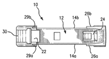
도 1 내지 도 5를 참조하면, 와이퍼 블레이드 커넥터의 실시예가, 단일 텅 와이퍼 아암들(60) 및 이중 텅 와이퍼 아암들(70) 양자 모두를 포함하는, 복수 유형의 와이퍼 아암들에 와이퍼 블레이드(50)를 해제 가능하게 고정하는 역할을 할 수 있을 것이다. 와이퍼 블레이드 커넥터(10)는, 서로 반대편에서 마주보는 측벽들(14a, 14b)을 구비하는 세장형 몸체 부재(12)를 포함할 수 있으며, 이는 와이퍼 블레이드(50)의 장착 베이스(40)에 연결 가능할 수 있을 것이다. 커넥터(10)는, 커넥터 고정 구조물을 통해 장착 베이스(40)에 연결될 수 있을 것이다. 하나의 실시예에서, 도 1에 도시된 바와 같이, 커넥터(10)는, 리벳 통로(16) 및 아치형 리벳 클립(18)을 구비하는, 커넥터 고정 구조물을 갖도록 제공될 수 있으며, 리벳 통로(16)는, 측벽들(14a, 14b) 사이에서 연장될 수 있고, 이는, 하측에서 개방될 수 있으며 그리고 아치형 리벳 클립(18)에 대한 접근을 제공한다. 리벳 통로(16)는, 아치형 리벳 클립(18)의 직경보다 약간 작게 크기설정될 수 있으며, 그로 인해 와이퍼 블레이드(50)의 장착 베이스(40) 상에 위치되는 리벳(42)의 스냅-끼워맞춤식 포획 수용을 허용한다. 아치형 리벳 클립(18)은, 커넥터(10) 및 와이퍼 아암(60, 70)에 대한 와이퍼 블레이드(50) 및 그의 장착 베이스(40)의 선회 운동을 허용하도록 크기결정될 수 있을 것이다. 못들(pegs), 돌출부들 및/또는 리세스들, 리벳을 커넥터로 교체하는 것 및 장착 베이스 상에 수용 클립을 구비하는 것, 형상 끼워 맞춤식 연결들, 멈춤형 연결들(detented connections), 그리고 커넥터(10) 및 와이퍼 암(60, 70)에 대한 와이퍼 블레이드(50) 및 그의 장착 베이스(40)의 선회 운동을 허용하는 임의의 다른 방법들을 포함하는, 커넥터(10)를 장착 베이스(40)와 연결하기 위한 다른 공지된 또는 개발될 커넥터 고정 구조물들이, 본 개시 이내에서 예상된다.1-5, an embodiment of a wiper blade connector includes a
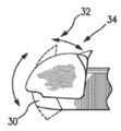
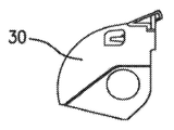
도 2는, 와이퍼 블레이드 커넥터(10)의 전방 단부에 위치되는, 와이퍼 아암(60, 70)의 전방 텅(62, 72)을 수용하기 위한 제1 텅 수용 개구(22), 및 후방 단부에 위치되는, 이중 텅 와이퍼 아암(70)의 후방 텅(74)을 수용하기 위한 제2 텅 수용 개구(24)를 구비하는, 세장형 몸체 부재(12)의 상측 표면(20)을 예시한다. 와이퍼 블레이드 커넥터(10)의 전방 단부의 서로 반대편의 측면들 상에 위치되는 경사부들(29a, 29b)이, 제1 텅 수용 개구(22) 내로의 전방 텅(62, 72)의 가이드된 수용을 위해 제공된다. 와이퍼 블레이드 커넥터(10)의 전방 단부는, 도 3에 도시된 바와 같이, 개방 위치(32)와 폐쇄 위치(34) 사이에서 회전될 수 있는, 부분적으로 회전 가능한 도어 부재(30)와 같은, 집어넣을 수 있는 잠금고정 메커니즘을 더 구비할 수 있을 것이다. 도 3a 및 도 3b는, 양자 모두 와이퍼 블레이드 커넥터(10)의 전방 단부와 함께 하는 그리고 개별적으로 와이퍼 블레이드 커넥터(10)와 분리되어, 축(27)을 중심으로 회전 가능한 것인, 부분적으로 회전 가능한 도어 부재(30)에 대한 격리된 도면들을 제공한다. 인덴트들이 선택적으로, 부분적으로 회전 가능한 도어 부재(30)가 개방 위치(32)로부터 폐쇄 위치(34)로 이동할 때, 벌어지는 후드(28)와 맞물림에 의해 부분적으로 회전 가능한 도어 부재(30)의 폐쇄 위치(34)를 고정하는 것을 돕기 위해 구비될 수 있을 것이다. 제한 없이, 힌지형 잠금구, 외팔보형 잠금구, 및 스프링 잠금구를 포함하는, 당해 기술분야에 공지된 다른 잠금고정 메커니즘들이, 회전 가능한 도어 부재(30)의 자리에 또한 사용될 수 있을 것이다.2 is located at the front end of the
대응하는 측벽들(14a, 14b)로부터 외향으로 돌출하는 쇼울더 부재들(26a, 26b)이, 와이퍼 블레이드 커넥터(10)의 후방 단부에 구비된다. 쇼울더 부재들(26a, 26b)은, 도 4에 도시된 바와 같이, 단일 텅 와이퍼 아암(60)의 반대편에 놓이는 측면들 상에 위치되는, 대응하는 후방 날개 부재들(36a, 36b)을 해제 가능하게 맞물도록 크기결정되고 성형된다. 도 4에 추가로 도시되는 바와 같이, 일부 와이퍼 아암들은, 제1 텅(62, 72)으로부터 멀게 놓이는 후방 단부를 향해 좁아질 수 있을 것이다. 따라서, 본 발명의 일부 실시예에서, 특정 와이퍼 아암들의 좁아지는 형상을 수용하기 위해 커넥터(10)의 측벽들(14a, 14b)을 좁아지게 하는 것이, 유리하다.The
도 6을 참조하면, 와이퍼 블레이드 커넥터(10)는, 대응하는 쇼울더 부재들(26a, 26b) 내에 후방 날개 부재들(36a, 36b)을 맞물리게 함에 의해, 그리고 방향 화살표들에 의해 도시되는 바와 같이, 부분적으로 회전 가능한 도어 부재(30)가 개방 위치(32)에 놓일 때, 경사부들(29a, 29b)이 제1 텅 수용 개구(22) 내부에서의 맞물린 수용으로 전방 텅(62)을 가이드하도록, 단일 텅 와이퍼 아암들을 향해 상방으로 와이퍼 블레이드 커넥터(10)를 회전시킴에 의해, 단일 텅 와이퍼 아암(60)에 연결된다. 부분적으로 회전 가능한 도어 부재(30)는 이어서, 폐쇄 위치(34)로 회전되며, 그로 인해 와이퍼 블레이드 커넥터(10)를 단일 텅 와이퍼 아암(60)에 잠금고정하도록 한다. 부분적으로 회전 가능한 도어 부재(30)는, 사용자가 개방 위치(32)와 폐쇄 위치(34) 사이에서 부분적으로 회전 가능한 도어 부재(30)를 회전시키기 위한 파지 지점을 제공하는, 벌어지는 후드(28)를 구비한다.Referring to Figure 6, the
도 5에 도시되는, 이중 텅 와이퍼 아암(70)이, 이상에 설명된 바와 같은, 단일 텅 와이퍼 아암(60)에 대한 와이퍼 블레이드 커넥터(10)의 부착과 유사한 프로세세에서, 와이퍼 블레이드 커넥터(10)에 해제 가능하게 고정될 수 있을 것이다. 도 7을 참조하면, 와이퍼 블레이드 커넥터(10)는, 후방 텅 수용 개구(24) 내부에 후방 텅(74)을 맞물리게 함에 의해, 그리고 방향 화살표들에 의해 도시되는 바와 같이, 부분적으로 회전 가능한 도어 부재(30)가 개방 위치(32)에 놓일 때, 전방 텅(72)이 제1 텅 수용 개구(22)와 일직선 상에 놓이며 그리고 제1 텅 수용 개구(22)와 맞물리도록, 상방으로 블레이드 커넥터를 회전시킴에 의해, 이중 텅 와이퍼 아암(70)에 연결된다. 경사부들(29a, 29b)은, 이중 텅 와이퍼 아암(70)이 쇼울더 부재들(26a, 26b)을 중심으로 회전될 때, 전방 텅 수용 개구(22) 내부에서 전방 텅(72)의 가이드된 수용을 제공하는 것을 지원한다. 부분적으로 회전 가능한 도어 부재(30)는 이어서, 폐쇄 위치(34)로 회전되며, 그로 인해 와이퍼 블레이드 커넥터(10)를 이중 텅 와이퍼 아암(70)에 잠금고정하도록 한다.In a process similar to the attachment of the
도 8에 도시된 바와 같이, 단일 텅 와이퍼 아암(60)에, 또는 이중 텅 와이퍼 아암(70)에, 와이퍼 블레이드 커넥터(10)를 고정한 이후에, 와이퍼 블레이드(50)는, 장착 베이스(40) 내에 위치되는 리벳(42)을 아치형 리벳 클립(18) 내로 스냅결합시킴에 의해 부착될 수 있고, 그로 인해, 예를 들어 도 9 및 도 10에 도시된 바와 같이, 와이퍼 블레이드 조립체를 완성하도록 한다.8, after fixing the
도 11 내지 도 18은, 전방 단부(113a) 및 후방 단부(113b)를 구비하는 세장형 몸체 부재(112)를 포함할 수 있는, 와이퍼 블레이드 커넥터(100)의 부가적인 실시예를 도시한다. 세장형 몸체 부재는, 서로 반대편에 놓이는 측벽들(114a, 114b) 뿐만 아니라 상측 표면(120)으로 구성될 수 있을 것이다. 아치형 리벳 클립(118)에 대한 접근을 그로 인해 제공하도록 하측에서 개방될 수 있는, 리벳 통로(116)가, 측벽들(114a, 114b) 사이에 연장되도록 한정될 수 있을 것이다. 리벳 통로(116) 및 클립(118)은, 실질적으로 커넥터(10) 실시예에 따라, 장착 베이스(40) 내의 리벳(42)과 맞물리고 리벳(42)을 고정하도록, 크기결정되고 치수결정될 수 있을 것이다.11-18 show additional embodiments of the
제1 텅 개구(122)가, 전방 단부(113b) 근처에 또는 그에 가깝게 제공될 수 있으며, 그리고 제2 텅 개구(124)가, 후방 단부(113a) 근처에 또는 그에 가깝게 제공될 수 있을 것이다. 커넥터(100)는, 개방 위치(132)와 폐쇄 위치(134) 사이에서 종방향으로 이동 가능하거나 슬라이딩 가능할 수 있는, 캡(130)을 더 구비할 수 있고, 여기서 제1 텅 개구(122)는, 캡(130)이 개방 위치(132)에 놓이는 동안에, 대부분 노출된다. 캡(130)은 또한, 탈착 가능할 수 있을 것이다. 도 11 내지 도 17은, 개방 위치(132)의 캡(130)을 동반하는 커넥터(100)의 실시예를 예시한다. 도 18은, 폐쇄 위치의 캡(130)을 동반하는 커넥터(100)의 이러한 실시예를 예시한다. 캡(130)의 슬라이딩을 수용하기 위해, 하나 이상의 측방 채널(131a)이, 측벽들(114a, 114b) 중의 적어도 하나 상에 제공될 수 있을 것이다. 하나의 실시예에서, 한 쌍의 측방 채널(131a)이 제공되며, 각 측방 채널은 서로 반대편에 놓이는 측벽(114a, 114b) 상에 놓인다. 측방 채널들(131a)은 실질적으로, 측방 채널(131a)이 그에 제공되는 개별적인 측벽(114a, 114b)과 실질적으로 동일 평면 상에 놓이는, 홈들 또는 슬롯들로서 구성될 수 있을 것이다. 하나 이상의 측방 채널은 각각, 종방향으로 연장되는 상측 에지와 종방향으로 연장되는 하측 에지 사이의 측벽(114a)의 부분에 의해, 한정될 수 있을 것이다. 이러한 상측 에지는, 대응하는 하측 에지와 실질적으로 동일한 거리만큼, 자체의 개별적인 측벽(114a, 114b)으로부터 멀어지게 돌출할 수 있을 것이다. 몸체 부재(112)는, 전방 단부(113b) 근처의 그리고 하나 이상의 측방 채널(131a) 각각에 인접한, 상측 캡 지지 표면(133a)을 더 구비할 수 있을 것이다. 제2 텅 개구(124)에 대한 것으로서, 일부 실시예들은, 제2 텅 개구(124)로 돌출하는 후방 탭(138)을 구비한다. 제2 텅 개구(124)는, 몸체 부재(112)의 후방 단부(113a) 근처에 위치설정될 수 있을 것이다.The first tongue opening 122 may be provided near or near the
도 15는, 캡(130)이 제거된, 그로 인해 전방 잠금고정 탭(135a)의 상측 부분이 예시되는, 커넥터(100)의 실시예를 예시한다. 전방 잠금고정 탭(135a)은, 실질적으로 직사각형 구성요소로서 도 15에 도시되는, 상측 부분 뿐만 아니라, 상측 부분을 향해 연장되며 그리고 세장형 몸체 부재(112)에 부착되는, 아암 부분을 구비한다. 전방 잠금고정 탭(135a)을 위한 다른 적절한 형상들 및 크기들이, 또한 사용될 수 있을 것이다. 아암 부분은, 본 명세서에 설명되는 바와 같은, 전방 텅 개구(122) 내로의 전방 텅의 삽입과 간섭하지 않도록 하기 위해, 제1 텅 개구(122) 내부에서 충분히 만입될 수 있을 것이다. 잠금고정 탭(135a)의 상측 부분은, 캡(130)의 상측 표면 상에 제공되는 잠금고정 탭 캐비티(135b)와 합치하게 성형되고 치수결정될 수 있을 것이다. 캡(130)이 폐쇄 위치(134)에 놓일 때, 전방 잠금고정 탭(135a)의 상측 부분은, 그로 인해 캡(130)을 폐쇄 위치(134)에서 고정하도록, 캐비티(135b) 내부에 합치하게 끼워질 수 있을 것이다. FIG. 15 illustrates an embodiment of the
제거된 캡(130)의 하측 사시도가 도 16에 도시된다. 측방 인덴트들 또는 돌출부들(131b)이, 캡(130)의 측벽들 내부에 도시된다. 각 측방 인덴트(131b)는, 캡(130)이 개방 위치와 폐쇄 위치 사이에서 슬라이딩될 때 측방 인덴트(131b)가 측방 채널(131a)을 따라 슬라이딩할 수 있도록, 측방 채널(131a)과 합치하게 성형될 수 있을 것이다. 상측 인덴트들 또는 돌출부들(133b)이 추가로, 캡(130)의 하측면 상에 제공될 수 있을 것이다. 각 상측 인덴트(133b)는, 상측 캡 지지 표면(133a)과 접촉할 수 있을 것이다. 각 상측 인덴트(133b)는, 캡(130)의 상측 부분으로부터 하방으로 돌출하며, 그리고 이점에 있어서, 상측 인덴트(133b)가 하방으로 돌출하는 거리는, 캡(130)의 상측 부분과 몸체 부재(112)의 상측 캡 지지 표면(133a) 사이의 틈새 거리일 수 있을 것이다. 부가적으로, 캡(130)의 상측 부분의 내부 하측면 상에, 전방 잠금고정 탭(135a)의 상측 부분과 합치하게 크기결정되고 치수결정될 수 있는, 잠금고정 탭 캐비티(135b)가 존재할 수 있을 것이다. 이 점에 있어서, 전방 잠금고정 탭(135a)의 상측 부분은, 캡(130)이 개방 위치(132)로부터 폐쇄 위치(134)로 이동될 때, 잠금고정 탭 채널(135c)을 따라 슬라이딩할 있으며, 그리고 전방 잠금고정 탭(135a)의 상측 부분은, 폐쇄 위치에서 캡(130)을 고정하기 위해 잠금고정 탭 캐비티(135b) 내부에 합치하게 끼워질 수 있을 것이다. 캡(130)의 내부 상측 표면의 일부분이, 캡이 폐쇄 위치에 놓일 때, 캐비티(135b) 내부에 잠금고정 탭(135a)을 고정하도록 하기 위해, 잠금고정 탭 채널(135c) 내로 탄력적으로 돌출할 수 있을 것이다. 캡의 내부 상측 표면은 또한, 잠금고정 탭(135a)의 삽입 및 고정을 용이하게 하기 위해 모깎기 될 수 있을 것이다. 개방 위치(132)와 폐쇄 위치(134) 사이에서 캡(130)을 슬라이딩시키도록 사용자에 의해 가해지는 것과 같은, 종방향 힘이, 그로 인해 캐비티(135b) 안팎으로의 탭(135a)의 상측 부분의 통과를 가능하게 하도록, 잠금고정 탭 채널(135c) 내부에서 캡(130)의 일부분을 탄력적으로 편향시키기 위해, 증가될 수 있을 것이다.The lower perspective view of the removed
도 17은 커넥터(100)에 대한 와이퍼 아암(60)의 고정을 도시한다. 캡(130)이 개방 위치(132)에 놓이는 경우, 와이퍼 아암(60, 70)의 전방 텅(62, 72)이, 제1 텅 개구(122) 내부에 수용될 수 있으며, 그리고 전방 텅(62, 72)은, 캡(130)이 폐쇄 위치(134)를 향해 슬라이딩될 때, 제1 텅 개구(122) 내부에 고정될 수 있을 것이다. 상측 인덴트(133b)의 돌출된 거리는 그로 인해, 전방 텅 개구(122) 내에 잠금고정될 때 캡(130)이 전방 텅(72)의 원위 부분 위에서 슬라이딩하는 것을 그로 인해 허용할 수 있는, 캡(130)과 캡 지지 표면(133a) 사이에 틈새 거리를 생성한다. 측방 채널들(131a)은 그로 인해, 개방 위치(132)와 폐쇄 위치(134) 사이에서 캡(130)의 종방향 슬라이딩을 허용하도록 작동할 수 있으며, 그리고 전방 탭(135a)은, 폐쇄 위치(134)에서 캡(130)을 고정하도록 작동할 수 있을 것이다. 적어도 제2 텅(74)의 원위 부분이 후방 탭(138) 아래에 배치되어, 그로 인해 제2 텅(74)을 제2 텅 수용 개구(124) 내에 고정하도록, 제2 텅 수용 개구(124) 내에 끼워질 수 있는, 제2 텅(74)이, 추가로 도시된다. 커넥터(100)는 단일 텅 와이퍼 아암 및 이중 텅 와이퍼 아암 양자 모두와 함께 사용 가능하다는 것이, 인식되어야 한다. 17 shows the fixation of the
와이퍼 블레이드가, 본 명세서에 설명되는 바와 같은 커넥터(10, 100)의 실시예와 함께 제공될 수 있을 것이다. 와이퍼 블레이드는, 본 발명과 함께하는 사용을 위해 적절한 임의의 유형의 것일 수 있을 것이다. 예를 들어, 와이퍼 블레이드는, 와이퍼 스트립을 지탱할 수 있는 복수의 프레임을 구비하며 그리고 복수의 프레임 내에 내장되거나 또는 복수의 프레임에 부착되는 장착 베이스를 구비하는, 전통적인 와이퍼 블레이드일 수 있을 것이다. 와이퍼 블레이드는 또한, 하나 이상의 스프링-탄성 빔, 와이퍼 스트립, 및 장착 베이스를 구비하는, 무-브라켓 유형 또는 "빔" 유형 와이퍼 블레이드일 수 있을 것이다. 와이퍼 블레이드는 또한, 빔 및 하나 이상의 프레임의 조합, 와이퍼 스트립, 및 장착 베이스를 구비하는, 하이브리드 와이퍼 블레이드일 수 있을 것이다. 와이퍼 블레이드의 유형과 무관하게, 와이퍼 블레이드는, 커넥터(10, 100)의 사용을 통해 와이퍼 블레이드를 와이퍼 아암(60, 70)에 연결하는, 장착 베이스를 구비할 수 있을 것이다. 이상에 논의된 바와 같이, 특정 실시예에서, 장착 베이스(40)는, 아치형 리벳 클립(18, 118) 내에 안착될 때까지, 커넥터(10, 100) 내의 리벳 통로(16, 116)를 통과할 수 있는, 2개의 서로 이격된 측벽 사이에서 연장되는 리벳을 구비한다. 다른 실시예에서, 장착 베이스(40)는, 장착 베이스(40)에 연결하기 위한 커넥터(10, 100)의 수단에 대응하는, 하나 이상의 핀, 구명, 리세스, 채널, 또는 다른 구조물을 구비할 수 있다.Wiper blades may be provided with embodiments of
특정 실시예에서, 커넥터(10, 100)는 바람직하게, 와이퍼 아암(60, 70)에 연결하기 이전에, 와이퍼 블레이드(50)의 장착 베이스(40)에 연결될 것이다. 다른 실시예에서, 커넥터(10, 100)는 바람직하게, 와이퍼 블레이드(50)의 장착 베이스(40)에 연결되기 이전에, 와이퍼 아암(60, 70)에 연결될 것이다. 다른 실시예에서, 커넥터(10, 100)는, 와이퍼 블레이드(50)의 장착 베이스(40)에 또는 와이퍼 아암(60, 70)에 먼저 연결될 수 있을 것이다.In certain embodiments, the
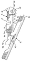
도 19 및 도 20은, 커넥터(210)를 장착 베이스(40)와 연결하기 위한 커넥터 고정 구조물의 부가적인 실시예를 예시한다. 커넥터(10)는, 리벳 통로(216) 및 아치형 리벳 클립(218)을 구비할 수 있으며, 아치형 리벳 클립은, 아치형 리벳 클립의 축이 리벳 통로의 중간을 따라 연장되는 라인으로부터 오프셋되도록, 리벳 통로에 실질적으로 수직으로 연장된다. 아치형 리벳 클립은, 제1 측벽과 제2 측벽(214a, 214b) 사이에서 연장될 수 있으며 그리고 와이퍼 블레이드를 커넥터에 해제 가능하게 고정하기 위해 구성되고 배치될 수 있으며, 그리고 아치형 리벳 클립은, 와이퍼 블레이드의 작동 도중에 상기 해제 가능하게 고정되는 와이퍼 블레이드가 선회하는 것을 허용하도록 크기결정된다. 리벳 통로는, 제1 측벽과 제2 측벽 사이에서 연장될 수 있으며, 그리고 아치형 리벳 클립에 대한 접근을 허용하도록 구성되고 배치될 수 있을 것이다. 이러한 특정 실시예는, 커넥터가, 블레이드가 와이퍼 전단 하향 위치 또는 와이퍼 후단 하향 위치에서 최대 각도로 경사질 때, 리벳 상에 커넥터를 유지할 "후크" 유사 형상을 가짐에 따라, 커넥터를 와이퍼 블레이드에 부착된 상태로 유지하기 위한 증가된 유지력(더욱 안정성을 제공함)을 허용한다. 일부 실시예에서, 리벳 통로(216)의 중간 라인과 리벳 통로의 상부로부터 아치형 리벳 클립의 축까지의 라인 사이에 형성되는 각도(α)가, 도 20에 도시된 바와 같이, 75 내지 90도 사이인 것이, 유리할 수 있을 것이다. 당업자는, 개시된 개념과 함께 논의된 오프셋된 리벳 클립이, 하나 이상의 벽을 구비하는 임의의 유형의 커넥터와 더불어 실시될 수 있다는 것을 인식할 것이다. 도 19 및 도 20에 도시된 실시예에서, 오프셋된 아치형 리벳 클립(218)은, 제1 측벽과 제2 측벽 사이에서 연장된다. 그러나, 그러한 오프셋된 리벳 클립들(218)은, 단일 벽 상에, 2개 초과의 벽 상에, 또는 모두가 아닌 일부의 벽 상에, 구현될 수 있을 것이다. 예를 들어, 일부 커넥터는, 한 쌍의 내부 측벽 및 한 쌍의 외부 측벽을 구비할 수 있을 것이다. 오프셋된 아치형 리벳 클립(218)은, 그러한 커넥터 내의 측벽들 중의 일부 또는 모두에 구비될 수 있을 것이다. 유사하게, 당업자는, 비록 도 19 및 도 20과 함께 사용되는 설명이 도 21에 도시된 장착 베이스(40)의 측벽들 내부에 배치되는 리벳(42)에 대한 연결을 논의하지만, 개시된 개념은, 리벳(42)을 내부 돌출부와 교체하는 것 또는 외부 돌출부를 갖는 장착 베이스를 구비하는 것을 포함하는, 임의의 적절한 연결 시스템과 함께 실시될 수 있다는 것을, 인식할 것이다. 19 and 20 illustrate additional embodiments of a connector securing structure for connecting the
비록 본 발명은 그의 바람직한 그리고 실용적인 실시예에 따라 도시되고 설명되었지만, 본 개시로부터의 벗어남은 본 발명의 사상 및 범위 이내에서 충분히 고려된다는 것이, 인식된다.Although the invention has been shown and described in accordance with its preferred and practical embodiments, it is recognized that deviations from the present disclosure are fully contemplated within the spirit and scope of the invention.
Claims (19)
제1 측벽, 제2 측벽, 및 제1 측벽과 제2 측벽 사이에서 연장되는 상측 표면을 구비하는, 몸체 부재; 및
커넥터 고정 구조물로서, 상기 커넥터 고정 구조물은 리벳 통로 및 아치형 리벳 클립을 구비하고, 상기 아치형 리벳 클립은 상기 리벳 통로로부터 실질적으로 수직으로 연장되는 것인, 커넥터 고정 구조물
을 포함하는 것인, 커넥터.As a connector for connecting the wiper blade,
A body member having a first sidewall, a second sidewall, and an upper surface extending between the first sidewall and the second sidewall; And
A connector fixing structure, wherein the connector fixing structure is provided with a rivet passageway and an arcuate rivet clip, wherein the arcuate rivet clip extends substantially vertically from the rivet passageway.
That includes, a connector.
상기 커넥터 고정 구조물은, 상기 제1 측벽 상에 구현되는 것인, 커넥터.According to claim 1,
The connector fixing structure, which is implemented on the first side wall, the connector.
상기 커넥터 고정 구조물은, 상기 제2 측벽 상에 구현되는 것인, 커넥터.According to claim 2,
The connector fixing structure, which is implemented on the second side wall, the connector.
상기 아치형 리벳 클립은, 와이퍼 블레이드의 리벳을 고정할 수 있는 것인, 커넥터.According to claim 1,
The arched rivet clip is to be able to secure the rivet of the wiper blade, the connector.
상기 아치형 리벳 클립은, 와이퍼 블레이드의 돌출부를 고정할 수 있는 것인, 커넥터.According to claim 1,
The arched rivet clip is to be able to secure the protrusion of the wiper blade, the connector.
와이퍼 스트립 및 장착 베이스를 포함하는 와이퍼 블레이드; 및
와이퍼 블레이드를 와이퍼 아암에 연결하기 위한 커넥터로서,
제1 측벽, 제2 측벽, 및 제1 측벽과 제2 측벽 사이에서 연장되는 상측 표면을 구비하는, 몸체 부재; 및
커넥터 고정 구조물로서, 상기 커넥터 고정 구조물은 리벳 통로 및 아치형 리벳 클립을 구비하고, 상기 아치형 리벳 클립은 상기 리벳 통로로부터 실질적으로 수직으로 연장되는 것인, 커넥터 고정 구조물
을 포함하는 것인, 커넥터
를 포함하는 것인, 와이퍼 블레이드 조립체.As a wiper blade assembly:
A wiper blade comprising a wiper strip and a mounting base; And
As a connector for connecting the wiper blade to the wiper arm,
A body member having a first sidewall, a second sidewall, and an upper surface extending between the first sidewall and the second sidewall; And
A connector fixing structure, wherein the connector fixing structure is provided with a rivet passageway and an arcuate rivet clip, wherein the arcuate rivet clip extends substantially vertically from the rivet passageway.
The connector that includes
It includes, wiper blade assembly.
상기 커넥터 고정 구조물은, 상기 제1 측벽 상에 구현되는 것인, 와이퍼 블레이드 조립체.The method of claim 6,
The connector fixing structure is implemented on the first side wall, the wiper blade assembly.
상기 커넥터 고정 구조물은, 상기 제2 측벽 상에 구현되는 것인, 와이퍼 블레이드 조립체.The method of claim 7,
The connector fixing structure is implemented on the second side wall, the wiper blade assembly.
상기 장착 베이스는, 리벳을 더 포함하며, 그리고 상기 아치형 리벳 클립은, 상기 리벳을 고정할 수 있는 것인, 와이퍼 블레이드 조립체.The method of claim 6,
The mounting base further includes a rivet, and the arched rivet clip is capable of fixing the rivet, a wiper blade assembly.
상기 장착 베이스는, 적어도 하나의 돌출부를 더 포함하며, 그리고 상기 아치형 리벳 클립은, 상기 적어도 하나의 돌출부를 고정할 수 있는 것인, 와이퍼 블레이드 조립체.The method of claim 6,
The mounting base further comprises at least one protrusion, and the arcuate rivet clip is capable of fixing the at least one protrusion, a wiper blade assembly.
전방 단부, 후방 단부, 제1 측벽, 제2 측벽, 및 제1 측벽과 제2 측벽 사이에서 연장되는 상측 표면을 구비하는, 세장형 몸체 부재;
커넥터 고정 구조물로서, 상기 커넥터 고정 구조물은 리벳 통로 및 아치형 리벳 클립을 구비하고, 상기 아치형 리벳 클립은 상기 리벳 통로에 실질적으로 수직으로 연장되는 것인, 커넥터 고정 구조물;
상기 세장형 몸체 부재의 제1 단부 근처에서 제1 측벽의 외측 표면의 일부분을 따라 종방향으로 연장되는, 제1 측방 채널;
상기 세장형 몸체 부재의 전방 단부를 향해 위치되는 제1 텅 수용 개구로서, 와이퍼 아암의 대응하는 전방 텅을 수용하도록 구성되는 것인, 제1 텅 수용 개구; 및
U-자 형상 캡으로서, 상측 벽 및 제1 측벽과 제2 측벽을 구비하며, 그리고 캡의 제1 측벽의 내부 표면 상에 제공되는 제1 측방 돌출부를 구비하고, 상기 제1 측방 돌출부는, 상기 캡이 개방 위치와 폐쇄 위치 사이에서 슬라이딩될 때, 상기 제1 측방 채널을 따라 슬라이딩하도록 상응하게 치수결정되고 위치설정되며, 상기 캡은, 와이퍼 아암 상의 상기 수용되는 대응하는 전방 텅을 고정하도록 작동 가능한 것인, U-자 형상 캡
을 포함하고,
상기 제1 측방 채널은, 상기 세장형 몸체 부재의 종방향에 대응하는 방향으로 배향될 수 있고, 상기 캡은 그로 인해 상측 표면에 실질적으로 평행하게 슬라이딩 가능한 것인, 커넥터.As a connector for fixing the wiper blade to the wiper arm,
An elongated body member having a front end, a rear end, a first side wall, a second side wall, and an upper surface extending between the first side wall and the second side wall;
A connector fixing structure, wherein the connector fixing structure is provided with a rivet passage and an arcuate rivet clip, wherein the arcuate rivet clip extends substantially perpendicular to the rivet passage;
A first lateral channel extending longitudinally along a portion of the outer surface of the first sidewall near the first end of the elongated body member;
A first tongue receiving opening positioned towards the front end of the elongated body member, the first tongue receiving opening being configured to receive a corresponding front tongue of the wiper arm; And
A U-shaped cap, having an upper wall and a first side wall and a second side wall, and a first lateral protrusion provided on the inner surface of the first side wall of the cap, wherein the first lateral protrusion comprises: When the cap slides between the open and closed positions, it is correspondingly dimensioned and positioned to slide along the first lateral channel, the cap operable to secure the corresponding corresponding front tongue on the wiper arm. , U-shaped cap
Including,
The first lateral channel can be oriented in a direction corresponding to the longitudinal direction of the elongated body member, and the cap is thereby slidable substantially parallel to the upper surface.
상기 세장형 몸체 부재의 제1 단부 근처에서 제2 측벽의 외측 표면의 일부분을 따라 종방향으로 연장되는, 제2 측방 채널; 및
상기 캡의 대향하는 내측 표면 상에 제공되는 부가적 측방 돌출부로서, 상기 캡이 개방 위치와 폐쇄 위치 사이에서 슬라이딩될 때, 상기 제2 측방 채널을 따라 슬라이딩하도록 상응하게 치수결정되고 위치설정되는 것인, 상기 부가적 측방 돌출부
를 더 포함하는 것인, 커넥터.The method of claim 11,
A second lateral channel extending longitudinally along a portion of the outer surface of the second sidewall near the first end of the elongated body member; And
An additional lateral protrusion provided on the opposing inner surface of the cap, which is correspondingly dimensioned and positioned to slide along the second lateral channel when the cap slides between an open position and a closed position. , The additional lateral protrusion
The connector that further comprises.
상기 제1 텅 개구 내부에 제공되는 전방 잠금고정 탭으로서, 상측 부분 및, 상측 부분을 상기 세장형 몸체 부재와 연결하는, 아암 부분을 구비하는 것인, 전방 잠금고정 탭; 및
상기 캡의 하측 표면 상에 제공되는 잠금고정 탭 채널로서, 상기 잠금고정 탭 채널은, 상기 캡이 개방 위치와 폐쇄 위치 사이에서 슬라이딩될 때, 상기 전방 잠금고정 탭의 상기 상측 부분이 상기 잠금고정 탭 채널을 따라 슬라이딩하는 것을 허용하도록 합치하게 치수결정되는 것인, 잠금고정 탭 채널
을 더 포함하는 것인, 커넥터.The method of claim 11,
A front locking and fixing tab provided inside the first tongue opening, the upper locking portion and an arm portion connecting the upper portion with the elongated body member; And
A locking tab channel provided on the lower surface of the cap, wherein the locking tab channel is such that when the cap is sliding between an open position and a closed position, the upper portion of the front locking tab is the locking tab. Locking tab channels, which are sized reasonably to allow sliding along the channel
It further comprises a connector.
상기 잠금고정 탭 채널에 인접하게 상기 캡 상에 제공되는 잠금고정 탭 캐비티로서, 상기 잠금고정 탭의 상기 상측 부분과 합치하게 치수결정되며 그리고 상기 캡이 폐쇄 위치에 놓일 때 상기 잠금고정 탭의 상기 상측 부분을 수용하도록 위치설정되는 것인, 잠금고정 탭 캐비티를 더 구비하는 것인, 커넥터.The method of claim 13,
A locking tab cavity provided on the cap adjacent to the locking tab channel, dimensioned to match the upper portion of the locking tab and when the cap is in the closed position, the upper side of the locking tab The connector, which is positioned to accommodate the portion, further comprising a locking tab cavity.
상기 캡의 탄력적 부분이, 상기 캐비티의 안팎으로 상기 잠금고정 탭의 상기 상측 부분을 슬라이딩시키기 위해 요구되는 종방향 힘을 증가시키기 위해, 상기 잠금고정 탭 채널 내로 돌출하는 것인, 커넥터. The method of claim 14,
Wherein the elastic portion of the cap protrudes into the locking tab channel to increase the longitudinal force required to slide the upper portion of the locking tab into and out of the cavity.
상기 캡의 하측 표면으로부터 돌출하는 상측 돌출부로서, 상기 세장형 몸체 부재의 상측 표면과 접촉하는 것인, 돌출부를 더 포함하는 것인, 커넥터.The method of claim 11,
An upper protrusion projecting from the lower surface of the cap, wherein the connector further comprises a protrusion, which is in contact with the upper surface of the elongated body member.
상기 상측 돌출부가 하측 표면으로부터 돌출하는 거리는, 상기 세장형 몸체 부재의 상기 상측 표면과 상기 캡 사이의 틈새 거리이고, 상기 틈새 거리는, 상기 캡이 폐쇄 위치로 슬라이딩될 때, 상기 캡이 상기 수용되는 전방 텅의 원위 부분 위로 슬라이딩하는 것을 허용하기에 충분한 것인, 커넥터.The method of claim 16,
The distance at which the upper protrusion protrudes from the lower surface is a clearance distance between the upper surface of the elongated body member and the cap, and the clearance distance is a front in which the cap is received when the cap is slid to the closed position. A connector that is sufficient to allow sliding over the distal portion of the tongue.
상기 아치형 리벳 클립은, 제1 측벽과 제2 측벽 사이에서 연장되며 그리고 와이퍼 블레이드를 커넥터에 해제 가능하게 고정하도록 구성되고 배치되며, 그리고 상기 아치형 리벳 클립은, 와이퍼 블레이드의 작동 도중에 상기 해제 가능하게 고정되는 와이퍼 블레이드가 선회하는 것을 허용하도록 크기결정되며; 그리고 상기 리벳 통로는, 제1 측벽과 제2 측벽 사이에서 연장되며, 상기 리벳 통로는, 상기 아치형 리벳 클립에 대한 접근을 허용하도록 구성되고 배치되는 것인, 커넥터.The method of claim 11,
The arched rivet clip extends between the first sidewall and the second sidewall and is configured and arranged to releasably secure the wiper blade to the connector, and the arched rivet clip is releasably secured during operation of the wiper blade. Sized to allow the wiper blade to be turned; And the rivet passageway extends between the first sidewall and the second sidewall, and the rivet passageway is constructed and arranged to allow access to the arched rivet clip.
상기 몸체 부재는, 전방 단부, 및 후방 단부를 더 구비하고:
상기 커넥터는,
상기 몸체 부재의 전방 단부 근처에서 제1 측벽의 외측 표면의 일부분을 따라 종방향으로 연장되는, 제1 측방 채널;
상기 몸체 부재의 전방 단부를 향해 위치되는 제1 텅 수용 개구로서, 와이퍼 아암의 대응하는 전방 텅을 수용하도록 구성되는 것인, 제1 텅 수용 개구; 및
U-자 형상 캡으로서, 상측 벽 및 제1 측벽과 제2 측벽을 구비하며, 그리고 캡의 제1 측벽의 내부 표면 상에 제공되는 제1 측방 돌출부를 구비하고, 상기 제1 측방 돌출부는, 상기 캡이 개방 위치와 폐쇄 위치 사이에서 슬라이딩될 때, 상기 제1 측방 채널을 따라 슬라이딩하도록 상응하게 치수결정되고 위치설정되며, 상기 캡은, 와이퍼 아암 상의 상기 수용되는 대응하는 전방 텅을 고정하도록 작동 가능한 것인, U-자 형상 캡
을 포함하며,
상기 제1 측방 채널은, 상기 몸체 부재의 종방향에 대응하는 방향으로 배향될 수 있고, 상기 캡은 그로 인해 상측 표면에 실질적으로 평행하게 슬라이딩 가능한 것인, 와이퍼 블레이드 조립체.The method of claim 6,
The body member further includes a front end and a rear end:
The connector,
A first lateral channel extending longitudinally along a portion of the outer surface of the first sidewall near the front end of the body member;
A first tongue receiving opening positioned towards the front end of the body member, the first tongue receiving opening being configured to receive a corresponding front tongue of the wiper arm; And
A U-shaped cap, having an upper wall and a first side wall and a second side wall, and a first lateral protrusion provided on the inner surface of the first side wall of the cap, wherein the first lateral protrusion comprises: When the cap slides between the open and closed positions, it is correspondingly dimensioned and positioned to slide along the first lateral channel, the cap operable to secure the corresponding corresponding front tongue on the wiper arm. , U-shaped cap
It includes,
The first lateral channel can be oriented in a direction corresponding to the longitudinal direction of the body member, and the cap is thereby slidable substantially parallel to the upper surface, the wiper blade assembly.
Applications Claiming Priority (3)
| Application Number | Priority Date | Filing Date | Title |
|---|---|---|---|
| US15/815,068 US10322699B2 (en) | 2011-07-29 | 2017-11-16 | Windshield wiper connector |
| US15/815,068 | 2017-11-16 | ||
| PCT/US2018/061476 WO2019103927A1 (en) | 2017-11-16 | 2018-11-16 | Windshield wiper connector |
Publications (1)
| Publication Number | Publication Date |
|---|---|
| KR20200085864A true KR20200085864A (en) | 2020-07-15 |
Family
ID=66631727
Family Applications (1)
| Application Number | Title | Priority Date | Filing Date |
|---|---|---|---|
| KR1020207017035A KR20200085864A (en) | 2017-11-16 | 2018-11-16 | Windshield wiper connector |
Country Status (8)
| Country | Link |
|---|---|
| EP (1) | EP3710318A4 (en) |
| JP (1) | JP2021503406A (en) |
| KR (1) | KR20200085864A (en) |
| CN (1) | CN111918799A (en) |
| AU (1) | AU2018372821A1 (en) |
| CA (1) | CA3082366A1 (en) |
| MX (1) | MX2020005254A (en) |
| WO (1) | WO2019103927A1 (en) |
Cited By (1)
| Publication number | Priority date | Publication date | Assignee | Title |
|---|---|---|---|---|
| WO2022014964A1 (en) | 2020-07-13 | 2022-01-20 | 주식회사 엘지에너지솔루션 | Electrode rolling device and method for performing multi-stage induction heating |
Family Cites Families (10)
| Publication number | Priority date | Publication date | Assignee | Title |
|---|---|---|---|---|
| CN100548760C (en) * | 2002-04-04 | 2009-10-14 | 罗伯特-博希股份公司 | Having one scrapes water arm and one and is articulated in the Wiper crank that this scrapes the swept area of wiper blade on the water arm |
| DE102008042236A1 (en) * | 2008-09-19 | 2010-04-01 | Robert Bosch Gmbh | Connection device for the articulated connection of a wiper blade |
| KR101703036B1 (en) * | 2009-07-10 | 2017-02-22 | 페더럴-모걸 코오포레이숀 | Multifunction wiper blade connector and assembly |
| TWM397336U (en) * | 2010-09-30 | 2011-02-01 | Zhi-Ming Yang | Wiper holder |
| CN202115476U (en) * | 2011-06-14 | 2012-01-18 | 杨志铭 | Windshield wiper combining seat capable of preventing driving wiper arm from loosening |
| WO2013016493A1 (en) * | 2011-07-28 | 2013-01-31 | Pylon Manufacturing Corp. | Windshield wiper adapter, connector and assembly |
| US9108595B2 (en) * | 2011-07-29 | 2015-08-18 | Pylon Manufacturing Corporation | Windshield wiper connector |
| DE102013102011A1 (en) * | 2013-02-28 | 2014-08-28 | Valeo Wischersysteme Gmbh | Wiper blade for cleaning vehicle windows and wiper device |
| US9555775B2 (en) * | 2013-03-15 | 2017-01-31 | Illinois Tool Works Inc. | Connectors and connector kit for attachment of a windshield wiper blade to multiple types of windshield wiper arms |
| DE102015215103A1 (en) * | 2015-08-07 | 2017-02-09 | Robert Bosch Gmbh | Wiper blade adapter |
-
2018
- 2018-11-16 JP JP2020526943A patent/JP2021503406A/en active Pending
- 2018-11-16 CN CN201880085812.7A patent/CN111918799A/en active Pending
- 2018-11-16 KR KR1020207017035A patent/KR20200085864A/en not_active Application Discontinuation
- 2018-11-16 EP EP18881972.6A patent/EP3710318A4/en not_active Withdrawn
- 2018-11-16 MX MX2020005254A patent/MX2020005254A/en unknown
- 2018-11-16 AU AU2018372821A patent/AU2018372821A1/en not_active Abandoned
- 2018-11-16 WO PCT/US2018/061476 patent/WO2019103927A1/en unknown
- 2018-11-16 CA CA3082366A patent/CA3082366A1/en active Pending
Cited By (1)
| Publication number | Priority date | Publication date | Assignee | Title |
|---|---|---|---|---|
| WO2022014964A1 (en) | 2020-07-13 | 2022-01-20 | 주식회사 엘지에너지솔루션 | Electrode rolling device and method for performing multi-stage induction heating |
Also Published As
| Publication number | Publication date |
|---|---|
| AU2018372821A1 (en) | 2020-05-28 |
| CA3082366A1 (en) | 2019-05-31 |
| MX2020005254A (en) | 2020-08-24 |
| JP2021503406A (en) | 2021-02-12 |
| EP3710318A4 (en) | 2021-08-04 |
| WO2019103927A1 (en) | 2019-05-31 |
| CN111918799A (en) | 2020-11-10 |
| EP3710318A1 (en) | 2020-09-23 |
Similar Documents
| Publication | Publication Date | Title |
|---|---|---|
| US11565661B2 (en) | Windshield wiper connector | |
| CA2898928C (en) | Windshield wiper connector | |
| US10322699B2 (en) | Windshield wiper connector | |
| KR101426005B1 (en) | Wiper blade | |
| CN106134012B (en) | A kind of electric coupler component | |
| KR101332690B1 (en) | Connecting apparatus for hinging a joining element rigidly connected to a wiper arm | |
| BRPI0609368A2 (en) | lever-mounted connector assembly with a position-securing device | |
| EP3072756B1 (en) | Connector element for connecting together windscreen wiper blades and their operating arms | |
| EP2783428B1 (en) | Lever type connector | |
| KR20200085864A (en) | Windshield wiper connector | |
| JPH07298450A (en) | Mounting structure of housing cover for harness | |
| JP6261035B2 (en) | Electric wire guide device | |
| US11247641B2 (en) | Windshield wiper connector | |
| JPH09163552A (en) | Electric connection box | |
| KR102048825B1 (en) | Anchor cover apparatus for child seat | |
| US11433857B2 (en) | Windshield wiper connector and assembly | |
| EP3840133B1 (en) | Lever-type connector | |
| CN211484110U (en) | Rotation axis limit structure, lid subassembly and cooking utensil | |
| KR102581423B1 (en) | Windshield Wiper Blade Adapter | |
| CN114336148A (en) | Holding frame for a plug connector | |
| WO2022035883A1 (en) | Windshield wiper connector | |
| EP1434312A2 (en) | Connector for electrical systems | |
| JP2003203711A (en) | Assembling method for protective cap, inner connector unit, and male connector |
Legal Events
| Date | Code | Title | Description |
|---|---|---|---|
| A201 | Request for examination | ||
| E902 | Notification of reason for refusal | ||
| E601 | Decision to refuse application |