BR112015023645B1 - DISPOSABLE ABSORBENT ITEM, METHOD OF FORMING AN ABSORBENT COMPOSITE, ITEM COMPRISING ABSORBENT COMPOSITE AND METHOD OF MANUFACTURING AN ABSORBENT COMPOSITE LAMINATE FOR A DISPOSABLE ABSORBENT ITEM - Google Patents
DISPOSABLE ABSORBENT ITEM, METHOD OF FORMING AN ABSORBENT COMPOSITE, ITEM COMPRISING ABSORBENT COMPOSITE AND METHOD OF MANUFACTURING AN ABSORBENT COMPOSITE LAMINATE FOR A DISPOSABLE ABSORBENT ITEM Download PDFInfo
- Publication number
- BR112015023645B1 BR112015023645B1 BR112015023645-6A BR112015023645A BR112015023645B1 BR 112015023645 B1 BR112015023645 B1 BR 112015023645B1 BR 112015023645 A BR112015023645 A BR 112015023645A BR 112015023645 B1 BR112015023645 B1 BR 112015023645B1
- Authority
- BR
- Brazil
- Prior art keywords
- fabric
- sap
- absorbent
- particles
- absorbent composite
- Prior art date
Links
- 239000002250 absorbent Substances 0.000 title claims abstract description 352
- 230000002745 absorbent Effects 0.000 title claims abstract description 352
- 239000002131 composite material Substances 0.000 title claims abstract description 172
- 238000004519 manufacturing process Methods 0.000 title claims abstract description 38
- 238000000034 method Methods 0.000 title claims description 111
- 239000002245 particle Substances 0.000 claims abstract description 243
- 239000004744 fabric Substances 0.000 claims abstract description 222
- 239000000835 fiber Substances 0.000 claims abstract description 30
- 239000000853 adhesive Substances 0.000 claims description 117
- 230000001070 adhesive effect Effects 0.000 claims description 116
- 239000012530 fluid Substances 0.000 claims description 49
- 239000000203 mixture Substances 0.000 claims description 15
- 238000004049 embossing Methods 0.000 claims description 13
- 239000011159 matrix material Substances 0.000 claims description 13
- 230000005012 migration Effects 0.000 claims description 13
- 238000013508 migration Methods 0.000 claims description 13
- 239000011148 porous material Substances 0.000 claims description 12
- 238000009826 distribution Methods 0.000 claims description 8
- 230000035515 penetration Effects 0.000 claims description 7
- 238000000151 deposition Methods 0.000 claims description 6
- 238000010438 heat treatment Methods 0.000 claims description 6
- 230000003213 activating effect Effects 0.000 claims description 3
- 230000004927 fusion Effects 0.000 claims description 3
- 238000003475 lamination Methods 0.000 claims description 3
- 238000002156 mixing Methods 0.000 claims description 2
- 239000011347 resin Substances 0.000 claims description 2
- 229920005989 resin Polymers 0.000 claims description 2
- 230000004913 activation Effects 0.000 claims 2
- 230000008021 deposition Effects 0.000 claims 1
- 230000002401 inhibitory effect Effects 0.000 claims 1
- 238000010030 laminating Methods 0.000 claims 1
- 239000004745 nonwoven fabric Substances 0.000 abstract description 2
- 229920000247 superabsorbent polymer Polymers 0.000 description 378
- 239000011162 core material Substances 0.000 description 151
- 239000010410 layer Substances 0.000 description 130
- 239000000463 material Substances 0.000 description 60
- 239000007788 liquid Substances 0.000 description 43
- 230000008569 process Effects 0.000 description 40
- 239000000758 substrate Substances 0.000 description 28
- 239000000047 product Substances 0.000 description 26
- 238000010276 construction Methods 0.000 description 19
- 238000010521 absorption reaction Methods 0.000 description 17
- 230000033001 locomotion Effects 0.000 description 14
- 239000011230 binding agent Substances 0.000 description 13
- 230000008901 benefit Effects 0.000 description 12
- 210000004013 groin Anatomy 0.000 description 12
- 239000011248 coating agent Substances 0.000 description 11
- 238000000576 coating method Methods 0.000 description 11
- 230000035699 permeability Effects 0.000 description 11
- 238000013461 design Methods 0.000 description 9
- 230000006870 function Effects 0.000 description 9
- 210000002414 leg Anatomy 0.000 description 9
- 229910003460 diamond Inorganic materials 0.000 description 7
- 239000010432 diamond Substances 0.000 description 7
- 230000002209 hydrophobic effect Effects 0.000 description 7
- 230000007246 mechanism Effects 0.000 description 7
- 230000008961 swelling Effects 0.000 description 7
- 230000009286 beneficial effect Effects 0.000 description 6
- 208000028659 discharge Diseases 0.000 description 6
- 210000005069 ears Anatomy 0.000 description 6
- 239000007787 solid Substances 0.000 description 6
- 239000012790 adhesive layer Substances 0.000 description 5
- 230000006872 improvement Effects 0.000 description 5
- 229920006395 saturated elastomer Polymers 0.000 description 5
- 239000004094 surface-active agent Substances 0.000 description 5
- 206010021639 Incontinence Diseases 0.000 description 4
- 230000000903 blocking effect Effects 0.000 description 4
- 238000006073 displacement reaction Methods 0.000 description 4
- 238000005342 ion exchange Methods 0.000 description 4
- 230000008447 perception Effects 0.000 description 4
- 239000004033 plastic Substances 0.000 description 4
- 229920003023 plastic Polymers 0.000 description 4
- 239000007921 spray Substances 0.000 description 4
- 230000006641 stabilisation Effects 0.000 description 4
- 238000011105 stabilization Methods 0.000 description 4
- 230000000087 stabilizing effect Effects 0.000 description 4
- 238000012549 training Methods 0.000 description 4
- 230000004888 barrier function Effects 0.000 description 3
- 210000001217 buttock Anatomy 0.000 description 3
- 239000000470 constituent Substances 0.000 description 3
- 239000002480 mineral oil Substances 0.000 description 3
- 235000010446 mineral oil Nutrition 0.000 description 3
- 229920000139 polyethylene terephthalate Polymers 0.000 description 3
- 239000005020 polyethylene terephthalate Substances 0.000 description 3
- -1 polypropylene Polymers 0.000 description 3
- 238000012545 processing Methods 0.000 description 3
- 230000007480 spreading Effects 0.000 description 3
- 238000003892 spreading Methods 0.000 description 3
- 238000012876 topography Methods 0.000 description 3
- 210000000689 upper leg Anatomy 0.000 description 3
- 239000011800 void material Substances 0.000 description 3
- 239000004698 Polyethylene Substances 0.000 description 2
- 239000004743 Polypropylene Substances 0.000 description 2
- 208000003251 Pruritus Diseases 0.000 description 2
- 102100021816 Splicing factor 3B subunit 3 Human genes 0.000 description 2
- 101710190370 Splicing factor 3B subunit 3 Proteins 0.000 description 2
- 239000004599 antimicrobial Substances 0.000 description 2
- 238000003491 array Methods 0.000 description 2
- 210000001124 body fluid Anatomy 0.000 description 2
- 239000011449 brick Substances 0.000 description 2
- 230000001934 delay Effects 0.000 description 2
- 239000002781 deodorant agent Substances 0.000 description 2
- 238000010586 diagram Methods 0.000 description 2
- 230000000694 effects Effects 0.000 description 2
- 238000005516 engineering process Methods 0.000 description 2
- 230000001747 exhibiting effect Effects 0.000 description 2
- 238000011049 filling Methods 0.000 description 2
- 230000005484 gravity Effects 0.000 description 2
- 238000007373 indentation Methods 0.000 description 2
- 239000003456 ion exchange resin Substances 0.000 description 2
- 229920003303 ion-exchange polymer Polymers 0.000 description 2
- 238000011068 loading method Methods 0.000 description 2
- 230000014759 maintenance of location Effects 0.000 description 2
- 238000002844 melting Methods 0.000 description 2
- 230000008018 melting Effects 0.000 description 2
- 230000008520 organization Effects 0.000 description 2
- 229920000573 polyethylene Polymers 0.000 description 2
- 229920001155 polypropylene Polymers 0.000 description 2
- 230000002265 prevention Effects 0.000 description 2
- 230000001737 promoting effect Effects 0.000 description 2
- 238000003860 storage Methods 0.000 description 2
- XLYOFNOQVPJJNP-UHFFFAOYSA-N water Substances O XLYOFNOQVPJJNP-UHFFFAOYSA-N 0.000 description 2
- 238000009736 wetting Methods 0.000 description 2
- 239000004372 Polyvinyl alcohol Substances 0.000 description 1
- 229920002472 Starch Polymers 0.000 description 1
- 238000002835 absorbance Methods 0.000 description 1
- 230000009471 action Effects 0.000 description 1
- 230000002776 aggregation Effects 0.000 description 1
- 238000004220 aggregation Methods 0.000 description 1
- 230000004075 alteration Effects 0.000 description 1
- 239000011324 bead Substances 0.000 description 1
- 239000013060 biological fluid Substances 0.000 description 1
- 230000005540 biological transmission Effects 0.000 description 1
- 230000015572 biosynthetic process Effects 0.000 description 1
- 238000007664 blowing Methods 0.000 description 1
- 230000037396 body weight Effects 0.000 description 1
- 239000006227 byproduct Substances 0.000 description 1
- 230000008859 change Effects 0.000 description 1
- 239000003795 chemical substances by application Substances 0.000 description 1
- 239000000084 colloidal system Substances 0.000 description 1
- 230000000295 complement effect Effects 0.000 description 1
- 230000006835 compression Effects 0.000 description 1
- 238000007906 compression Methods 0.000 description 1
- 229920001577 copolymer Polymers 0.000 description 1
- 238000005520 cutting process Methods 0.000 description 1
- 230000003247 decreasing effect Effects 0.000 description 1
- 230000009977 dual effect Effects 0.000 description 1
- 239000002360 explosive Substances 0.000 description 1
- 210000000416 exudates and transudate Anatomy 0.000 description 1
- 210000003608 fece Anatomy 0.000 description 1
- 239000006260 foam Substances 0.000 description 1
- 230000005764 inhibitory process Effects 0.000 description 1
- 230000001788 irregular Effects 0.000 description 1
- 239000010808 liquid waste Substances 0.000 description 1
- 238000012423 maintenance Methods 0.000 description 1
- 239000000155 melt Substances 0.000 description 1
- 239000012528 membrane Substances 0.000 description 1
- 230000000116 mitigating effect Effects 0.000 description 1
- 230000037361 pathway Effects 0.000 description 1
- 229920001495 poly(sodium acrylate) polymer Polymers 0.000 description 1
- 229920000058 polyacrylate Polymers 0.000 description 1
- 239000004626 polylactic acid Substances 0.000 description 1
- 229920000642 polymer Polymers 0.000 description 1
- 229920000098 polyolefin Polymers 0.000 description 1
- 229920002451 polyvinyl alcohol Polymers 0.000 description 1
- 239000000843 powder Substances 0.000 description 1
- 230000005855 radiation Effects 0.000 description 1
- 230000001105 regulatory effect Effects 0.000 description 1
- 238000012552 review Methods 0.000 description 1
- 239000002356 single layer Substances 0.000 description 1
- NNMHYFLPFNGQFZ-UHFFFAOYSA-M sodium polyacrylate Chemical compound [Na+].[O-]C(=O)C=C NNMHYFLPFNGQFZ-UHFFFAOYSA-M 0.000 description 1
- 239000004834 spray adhesive Substances 0.000 description 1
- 238000005507 spraying Methods 0.000 description 1
- 235000019698 starch Nutrition 0.000 description 1
- 239000000126 substance Substances 0.000 description 1
- 238000006467 substitution reaction Methods 0.000 description 1
- 230000002522 swelling effect Effects 0.000 description 1
- 230000002195 synergetic effect Effects 0.000 description 1
- 229920001169 thermoplastic Polymers 0.000 description 1
- 239000004416 thermosoftening plastic Substances 0.000 description 1
- 238000012546 transfer Methods 0.000 description 1
- 230000007704 transition Effects 0.000 description 1
- 238000011144 upstream manufacturing Methods 0.000 description 1
- 210000002700 urine Anatomy 0.000 description 1
Images


Classifications
-
- A—HUMAN NECESSITIES
- A61—MEDICAL OR VETERINARY SCIENCE; HYGIENE
- A61F—FILTERS IMPLANTABLE INTO BLOOD VESSELS; PROSTHESES; DEVICES PROVIDING PATENCY TO, OR PREVENTING COLLAPSING OF, TUBULAR STRUCTURES OF THE BODY, e.g. STENTS; ORTHOPAEDIC, NURSING OR CONTRACEPTIVE DEVICES; FOMENTATION; TREATMENT OR PROTECTION OF EYES OR EARS; BANDAGES, DRESSINGS OR ABSORBENT PADS; FIRST-AID KITS
- A61F13/00—Bandages or dressings; Absorbent pads
- A61F13/15—Absorbent pads, e.g. sanitary towels, swabs or tampons for external or internal application to the body; Supporting or fastening means therefor; Tampon applicators
- A61F13/53—Absorbent pads, e.g. sanitary towels, swabs or tampons for external or internal application to the body; Supporting or fastening means therefor; Tampon applicators characterised by the absorbing medium
- A61F13/539—Absorbent pads, e.g. sanitary towels, swabs or tampons for external or internal application to the body; Supporting or fastening means therefor; Tampon applicators characterised by the absorbing medium characterised by the connection of the absorbent layers with each other or with the outer layers
-
- A—HUMAN NECESSITIES
- A61—MEDICAL OR VETERINARY SCIENCE; HYGIENE
- A61F—FILTERS IMPLANTABLE INTO BLOOD VESSELS; PROSTHESES; DEVICES PROVIDING PATENCY TO, OR PREVENTING COLLAPSING OF, TUBULAR STRUCTURES OF THE BODY, e.g. STENTS; ORTHOPAEDIC, NURSING OR CONTRACEPTIVE DEVICES; FOMENTATION; TREATMENT OR PROTECTION OF EYES OR EARS; BANDAGES, DRESSINGS OR ABSORBENT PADS; FIRST-AID KITS
- A61F13/00—Bandages or dressings; Absorbent pads
- A61F13/15—Absorbent pads, e.g. sanitary towels, swabs or tampons for external or internal application to the body; Supporting or fastening means therefor; Tampon applicators
- A61F13/15577—Apparatus or processes for manufacturing
- A61F13/15617—Making absorbent pads from fibres or pulverulent material with or without treatment of the fibres
- A61F13/15658—Forming continuous, e.g. composite, fibrous webs, e.g. involving the application of pulverulent material on parts thereof
-
- A—HUMAN NECESSITIES
- A61—MEDICAL OR VETERINARY SCIENCE; HYGIENE
- A61F—FILTERS IMPLANTABLE INTO BLOOD VESSELS; PROSTHESES; DEVICES PROVIDING PATENCY TO, OR PREVENTING COLLAPSING OF, TUBULAR STRUCTURES OF THE BODY, e.g. STENTS; ORTHOPAEDIC, NURSING OR CONTRACEPTIVE DEVICES; FOMENTATION; TREATMENT OR PROTECTION OF EYES OR EARS; BANDAGES, DRESSINGS OR ABSORBENT PADS; FIRST-AID KITS
- A61F13/00—Bandages or dressings; Absorbent pads
- A61F13/15—Absorbent pads, e.g. sanitary towels, swabs or tampons for external or internal application to the body; Supporting or fastening means therefor; Tampon applicators
- A61F13/53—Absorbent pads, e.g. sanitary towels, swabs or tampons for external or internal application to the body; Supporting or fastening means therefor; Tampon applicators characterised by the absorbing medium
- A61F13/531—Absorbent pads, e.g. sanitary towels, swabs or tampons for external or internal application to the body; Supporting or fastening means therefor; Tampon applicators characterised by the absorbing medium having a homogeneous composition through the thickness of the pad
- A61F13/532—Absorbent pads, e.g. sanitary towels, swabs or tampons for external or internal application to the body; Supporting or fastening means therefor; Tampon applicators characterised by the absorbing medium having a homogeneous composition through the thickness of the pad inhomogeneous in the plane of the pad
- A61F13/5323—Absorbent pads, e.g. sanitary towels, swabs or tampons for external or internal application to the body; Supporting or fastening means therefor; Tampon applicators characterised by the absorbing medium having a homogeneous composition through the thickness of the pad inhomogeneous in the plane of the pad having absorbent material located in discrete regions, e.g. pockets
-
- A—HUMAN NECESSITIES
- A61—MEDICAL OR VETERINARY SCIENCE; HYGIENE
- A61F—FILTERS IMPLANTABLE INTO BLOOD VESSELS; PROSTHESES; DEVICES PROVIDING PATENCY TO, OR PREVENTING COLLAPSING OF, TUBULAR STRUCTURES OF THE BODY, e.g. STENTS; ORTHOPAEDIC, NURSING OR CONTRACEPTIVE DEVICES; FOMENTATION; TREATMENT OR PROTECTION OF EYES OR EARS; BANDAGES, DRESSINGS OR ABSORBENT PADS; FIRST-AID KITS
- A61F13/00—Bandages or dressings; Absorbent pads
- A61F13/15—Absorbent pads, e.g. sanitary towels, swabs or tampons for external or internal application to the body; Supporting or fastening means therefor; Tampon applicators
- A61F13/53—Absorbent pads, e.g. sanitary towels, swabs or tampons for external or internal application to the body; Supporting or fastening means therefor; Tampon applicators characterised by the absorbing medium
- A61F13/531—Absorbent pads, e.g. sanitary towels, swabs or tampons for external or internal application to the body; Supporting or fastening means therefor; Tampon applicators characterised by the absorbing medium having a homogeneous composition through the thickness of the pad
- A61F13/532—Absorbent pads, e.g. sanitary towels, swabs or tampons for external or internal application to the body; Supporting or fastening means therefor; Tampon applicators characterised by the absorbing medium having a homogeneous composition through the thickness of the pad inhomogeneous in the plane of the pad
- A61F13/533—Absorbent pads, e.g. sanitary towels, swabs or tampons for external or internal application to the body; Supporting or fastening means therefor; Tampon applicators characterised by the absorbing medium having a homogeneous composition through the thickness of the pad inhomogeneous in the plane of the pad having discontinuous areas of compression
-
- A—HUMAN NECESSITIES
- A61—MEDICAL OR VETERINARY SCIENCE; HYGIENE
- A61F—FILTERS IMPLANTABLE INTO BLOOD VESSELS; PROSTHESES; DEVICES PROVIDING PATENCY TO, OR PREVENTING COLLAPSING OF, TUBULAR STRUCTURES OF THE BODY, e.g. STENTS; ORTHOPAEDIC, NURSING OR CONTRACEPTIVE DEVICES; FOMENTATION; TREATMENT OR PROTECTION OF EYES OR EARS; BANDAGES, DRESSINGS OR ABSORBENT PADS; FIRST-AID KITS
- A61F13/00—Bandages or dressings; Absorbent pads
- A61F13/15—Absorbent pads, e.g. sanitary towels, swabs or tampons for external or internal application to the body; Supporting or fastening means therefor; Tampon applicators
- A61F13/53—Absorbent pads, e.g. sanitary towels, swabs or tampons for external or internal application to the body; Supporting or fastening means therefor; Tampon applicators characterised by the absorbing medium
- A61F13/534—Absorbent pads, e.g. sanitary towels, swabs or tampons for external or internal application to the body; Supporting or fastening means therefor; Tampon applicators characterised by the absorbing medium having an inhomogeneous composition through the thickness of the pad
- A61F13/535—Absorbent pads, e.g. sanitary towels, swabs or tampons for external or internal application to the body; Supporting or fastening means therefor; Tampon applicators characterised by the absorbing medium having an inhomogeneous composition through the thickness of the pad inhomogeneous in the plane of the pad, e.g. core absorbent layers being of different sizes
- A61F13/536—Absorbent pads, e.g. sanitary towels, swabs or tampons for external or internal application to the body; Supporting or fastening means therefor; Tampon applicators characterised by the absorbing medium having an inhomogeneous composition through the thickness of the pad inhomogeneous in the plane of the pad, e.g. core absorbent layers being of different sizes having discontinuous areas of compression
Abstract
método de fazer um compósito absorvente e artigos absorventes empregando o mesmo. descreve-se um compósito de núcleo absorvente para um artigo absorvente descartável. o compósito absorvente tem um primeiro tecido, um segundo tecido de lado de corpo, e uma pluralidade de agregados de partículas superabsorventes (sap) situados entre o primeiro tecido e segundo tecido. sobre cada de uma pluralidade de agregados de sap, um arranjo de locais de ligação espaçados fixam o segundo tecido para o primeiro tecido e formam uma bolsa na qual o agregado de sap é fixado entre o primeiro tecido e o segundo tecido. o segundo tecido de lado de corpo é um tecido não trançado volumoso incluindo fibras que entrelaçam pelo menos algumas partículas do agregado de sap.method of making an absorbent composite and absorbent articles employing the same. An absorbent core composite for a disposable absorbent article is described. The absorbent composite has a first fabric, a second body side fabric, and a plurality of superabsorbent particle aggregates (SAP) located between the first fabric and second fabric. On each of a plurality of sap aggregates, an arrangement of spaced attachment sites secure the second fabric to the first fabric and form a pocket in which the sap aggregate is secured between the first fabric and the second fabric. The second body side fabric is a bulky nonwoven fabric including fibers that interweave at least some particles of the sap aggregate.
Description
[001] O presente pedido reivindica o benefício do Pedido Provisório dos Estados Unidos No. de Série 61/801.620, depositado em 15 de março de 2013 (pendente), cuja divulgação é deste modo incorporada por referência para todos os fins e faz parte da presente divulgação.[001] The present application claims the benefit of United States Interim Application Serial No. 61/801,620, filed March 15, 2013 (pending), the disclosure of which is hereby incorporated by reference for all purposes and forms part of the present disclosure.
[002] A presente invenção refere-se genericamente a um compósito absorvente (ou laminado de núcleo absorvente) e um método de fazer um compósito absorvente. A presente invenção também refere-se geralmente a artigos absorventes descartáveis que utilizam compósitos absorventes e métodos de fazer os mesmos. Tais artigos absorventes descartáveis incluem fraldas, calças de treinamento, produtos de incontinência para adultos, produtos de absorção de exsudados corporais, produtos de higiene feminina e outros produtos absorventes (coletivamente, "artigos absorventes descartáveis" ou "produtos absorventes descartáveis").[002] The present invention relates generally to an absorbent composite (or absorbent core laminate) and a method of making an absorbent composite. The present invention also generally relates to disposable absorbent articles which utilize absorbent composites and methods of making the same. Such disposable absorbent articles include diapers, training pants, adult incontinence products, body exudate absorbent products, feminine care products and other absorbent products (collectively, "disposable absorbent articles" or "disposable absorbent products").
[003] Os artigos absorventes descartáveis empregam tipicamente três elementos estruturais básicos: uma folha de topo que forma a superfície interior, uma folha de fundo que forma a superfície exterior, e um núcleo absorvente que é interposto entre a folha de topo e a folha de fundo. A folha de topo é concebida para permitir a passagem do líquido a partir do exterior do artigo absorvente e através da folha de topo para o núcleo absorvente. A folha de topo pode ser feita de uma variedade de materiais hidrofílicos ou hidrofóbicos permeáveis a líquidos e vapor. A permeabilidade da folha de topo pode ser aumentada pela utilização de agentes de ativação de superfície ("surfactantes"). Surfactantes reduzem energia de superfície ou ângulo de contato da interface sólido-líquido e facilitam a passagem do líquido através da folha de topo.[003] Disposable absorbent articles typically employ three basic structural elements: a top sheet that forms the inner surface, a back sheet that forms the outer surface, and an absorbent core that is interposed between the top sheet and the top sheet. background. The topsheet is designed to allow the passage of liquid from outside the absorbent article and through the topsheet to the absorbent core. The top sheet can be made from a variety of liquid and vapor permeable hydrophilic or hydrophobic materials. Topsheet permeability can be increased by the use of surface activating agents ("surfactants"). Surfactants reduce surface energy or contact angle of the solid-liquid interface and facilitate liquid passage through the topsheet.
[004] A folha de fundo é concebida para impedir a passagem de fluido a partir do núcleo absorvente através da folha de fundo e para fora do artigo absorvente. A folha de fundo pode ser feita de uma película impermeável estendendo toda a largura do artigo ou uma combinação de material tipo tecido e película impermeável. A folha de fundo pode ter também propriedades de transmissão de vapor ("respirabilidade") que permitem que o vapor passe através da folha de fundo sem liberar fluidos armazenados no núcleo absorvente. A folha de fundo pode também ser feita a partir de um material não trançado transmissível de vapor, mas impermeável a líquido, tal como ligação-fiada, fusão-sopro, ligação-fiada ("SMS"); ligação-fiada, fusão-sopro, fusão- sopro, ligação-fiada ("SMMS"); fibras micro, nano, ou divisíveis; fiado por fusão ou fiado por laço; cardado; e similar.[004] The bottom sheet is designed to prevent the passage of fluid from the absorbent core through the bottom sheet and out of the absorbent article. The backing sheet can be made of an impermeable film extending the entire width of the article or a combination of fabric-like material and an impermeable film. The bottom sheet may also have vapor transmission ("breathability") properties that allow vapor to pass through the bottom sheet without releasing fluid stored in the absorbent core. The backsheet may also be made from a non-woven, vapor transmissible but liquid impervious material, such as spunbond, melt-blow, spunbond ("SMS"); bond-spun, melt-blow, melt-blow, bond-spun ("SMMS"); micro, nano, or divisible fibers; fusion spun or loop spun; carded; It's similar.
[005] O núcleo absorvente é concebido para conter e distribuir fluido que passa através da folha de topo.Um núcleo absorvente típico é feito de um alto ou superabsorvente polímero (SAP) estabilizado por uma matriz absorvente. O SAP é geralmente feito de materiais, tais como álcool polivinílico, poliacrilatos, vários amidos enxertados, e poliacrilato de sódio reticulado. O SAP pode estar na forma de partículas, fibras, espumas, trama, esferas, aglomerados de formas regulares ou irregulares, e películas. A matriz absorvente é normalmente uma pasta de papel sem fibras ou material semelhante. A matriz absorvente é muito volumosa em relação à folha de topo, folha de fundo, e SAP. A maior parte da espessura de uma fralda vem do núcleo absorvente.[005] The absorbent core is designed to contain and distribute fluid as it passes through the topsheet. A typical absorbent core is made of a high or superabsorbent polymer (SAP) stabilized by an absorbent matrix. SAP is generally made from materials such as polyvinyl alcohol, polyacrylates, various grafted starches, and cross-linked sodium polyacrylate. SAP can be in the form of particles, fibers, foams, webs, spheres, regular or irregular shaped agglomerates, and films. The absorbent matrix is normally a fiber-free pulp or similar material. The absorbent matrix is very bulky relative to the top sheet, bottom sheet, and SAP. Most of the thickness of a diaper comes from the absorbent core.
[006] Cada vez mais, consumidores de artigos absorventes estão exigindo artigos absorventes mais finos.Para satisfazer estas exigências, fabricas estão diminuindo espessura dos artigos absorventes por diminuir a quantidade de matriz absorvente usada em núcleos absorventes.Embora os núcleos absorventes resultantes sejam mais finos, eles sofrem de desempenho. Como quantidade de matriz absorvente é reduzida, é menos eficaz na estabilização do SAP- prevenção do SAP de migrar para o interior do núcleo absorvente. Como SAP migra para o interior do núcleo, o núcleo absorvente perde a sua eficácia e não tem capacidade de absorção uniforme. Por exemplo, o SAP que não é contido tende a se amontoar em áreas molhadas e é ineficaz para o tratamento de descargas posteriores.[006] Increasingly, consumers of absorbent articles are demanding thinner absorbent articles. To meet these requirements, factories are thinning absorbent articles by decreasing the amount of absorbent matrix used in absorbent cores. Although the resulting absorbent cores are thinner. , they suffer from performance. As the amount of absorbent matrix is reduced, it is less effective in stabilizing the SAP - preventing the SAP from migrating into the absorbent core. As SAP migrates into the core, the absorbent core loses its effectiveness and lacks uniform absorption capacity. For example, SAP that is not contained tends to pile up in wet areas and is ineffective for handling further discharge.
[007] Os fabricantes tentaram resolver este problema criando bolsas de SAP pequenas individuais ou colando o SAP. Estas soluções, no entanto, têm sido largamente mal sucedidas.As bolsas de SAP simplesmente limitam a migração para movimento dentro das bolsas. No entanto, porque ainda há um movimento das partículas, o núcleo absorvente não exibe absorção uniforme. Colar o SAP estabiliza o SAP, mas resulta em um núcleo absorvente desconfortavelmente rígido e uma perda na capacidade de dilatação do SAP. Os requerentes também descobriram que os métodos para conter o SAP podem ter um impacto negativo no SAP e na capacidade do núcleo absorvente para receber e distribuir as entradas.[007] Manufacturers have tried to solve this problem by creating individual small SAP pouches or by pasting the SAP. These solutions, however, have largely been unsuccessful. SAP exchanges simply limit migration to movement within exchanges. However, because there is still movement of the particles, the absorbent core does not exhibit uniform absorption. Pasting the SAP stabilizes the SAP but results in an uncomfortably rigid absorbent core and a loss in the SAP's ability to expand. Applicants have also found that methods for containing the SAP can negatively impact the SAP and the absorbent core's ability to receive and distribute the inputs.
[008] Assim, existe uma necessidade de um produto absorvente melhorado que contínua a tendência de diminuir espessura do produto, ao mesmo tempo minimizando rigidez do produto e por outro lado apresentando excelente absorvência e propriedades de manipulação de fluidos. A especificação de patente No. US 8.148.598, que é comumente atribuído e designa pelo menos um inventor comum tal como o presente pedido, descreve um melhoramento para o estado anterior da arte e serve como fundamento para a presente divulgação. O documento 598' de patente é aqui incorporado por referência na sua totalidade para todos os efeitos e feito uma parte da presente divulgação. A presente divulgação pode, em um aspecto, ser considerada como contínuando e aprofundando o esforço para fornecer produtos absorventes melhorados e métodos de fabricação.[008] Thus, there is a need for an improved absorbent product that continues the tendency to thin the product while minimizing product stiffness and otherwise exhibiting excellent absorbency and fluid handling properties. Patent Specification No. US 8,148,598, which is commonly assigned and designates at least one common inventor such as the present application, describes an improvement over the prior art and serves as the foundation for the present disclosure. Patent document 598' is hereby incorporated by reference in its entirety for all purposes and made a part of the present disclosure. The present disclosure can, in one aspect, be regarded as continuing and deepening the effort to provide improved absorbent products and manufacturing methods.
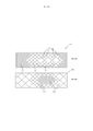
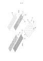
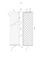
[009] Em um aspecto, a revelação fornece compósitos absorventes melhorados e métodos de fazer o compósito. Modalidades são divulgadas que focam na composição ou disposição dos componentes do compósito absorvente. Em uma modalidade, um compósito de núcleo absorvente para um artigo absorvente descartável tem um primeiro tecido, um segundo tecido de lado de corpo, e uma pluralidade de agregados de partículas superabsorventes (SAP) situados entre o primeiro tecido e segundo tecido. Sobre cada de uma pluralidade de agregados de SAP, um arranjo de locais de ligação espaçados fixa o segundo tecido para o primeiro tecido e formam uma bolsa na qual o agregado de SAP é fixado entre o primeiro tecido e o segundo tecido. O segundo tecido de lado de corpo é um tecido não trançado volumoso incluindo fibras que entrelaçam pelo menos algumas partículas do agregado de SAP. Em modalidades preferenciais, um padrão de adesivo pode é pré-aplicado no primeiro tecido (por exemplo, um padrão tendo uma pluralidade de loops interseptantes definindo regiões abertas livres de adesivo).[009] In one aspect, the disclosure provides improved absorbent composites and methods of making the composite. Embodiments are disclosed that focus on the composition or arrangement of the components of the absorbent composite. In one embodiment, an absorbent core composite for a disposable absorbent article has a first fabric, a second body-side fabric, and a plurality of superabsorbent particle aggregates (SAP) located between the first fabric and second fabric. On top of each of a plurality of SAP aggregates, an array of spaced apart binding sites secure the second tissue to the first tissue and form a pocket in which the SAP aggregate is secured between the first tissue and the second tissue. The second body side fabric is a bulky non-woven fabric including fibers that weave together at least some particles of the SAP aggregate. In preferred embodiments, an adhesive pattern may be pre-applied to the first fabric (e.g., a pattern having a plurality of intersecting loops defining adhesive-free open regions).
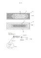
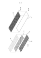
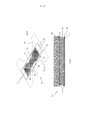
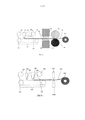
[010] Em outro aspecto, é revelado um método de fabricação de um laminado de compósito absorvente para um artigo absorvente descartável. O método implica transportar um primeiro tecido em posição para receber partículas superabsorventes (SAP) e depositar SAP no primeiro tecido para fornecer agregados discretos de SAP. Um segundo tecido de um não trançado volumoso é então transportado e posicionado em relação ao primeiro tecido de tal modo que fibras do não trançado volumoso enredam partículas em uma camada de topo de partículas do agregado de SAP. Isto assegura, pelo menos em parte, o agregado de SAP entre as mesmas. O primeiro e segundo tecidos são, então, ligados em uma rede de locais de ligação para formar um laminado alongado tendo uma pluralidade de bolsas de agregado de SAP, em que cada bolsa é definida por locais de ligação posicionados sobre um agregado de SAP e fixando o segundo tecido para o primeiro tecido; e transportar o laminado alongado, através do que o não trançado volumoso e bolsas inibem migração de partículas de SAP a partir de referidas bolsas. Em modalidades preferidas, os locais de ligação são pontos de ligação e/ou os locais de ligação formam bolsas em forma de diamante e uma grade correspondente sem quaisquer caminhos de linha reta diretos para as margens laterais.[010] In another aspect, a method of manufacturing an absorbent composite laminate for a disposable absorbent article is disclosed. The method involves transporting a first tissue in position to receive superabsorbent particles (SAP) and depositing SAP on the first tissue to provide discrete aggregates of SAP. A second fabric of a bulky nonwoven is then transported and positioned relative to the first fabric in such a way that fibers of the bulky nonwoven entangle particles in a top layer of particles of the SAP aggregate. This ensures, at least in part, the aggregation of SAP between them. The first and second fabrics are then bonded together in a network of binding sites to form an elongated laminate having a plurality of pockets of SAP array, wherein each pocket is defined by bonding sites positioned over an array of SAP and securing the second fabric to the first fabric; and transporting the elongated laminate, whereby the bulky nonwoven and pouches inhibit migration of SAP particles from said pouches. In preferred embodiments, the bonding sites are bonding points and/or the bonding sites form diamond-shaped pockets and a corresponding grid without any direct straight line paths to the side edges.
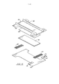
[011] Um artigo absorvente descartável é também revelado tendo um corpo de chassi definido por uma primeira margem de extremidade e uma segunda margem de extremidade afastada longitudinalmente da primeira margem de extremidade, as margens de extremidade parcialmente definindo região de cintura frontal e posterior que podem ser presas sobre uma cintura de um usuário. O artigo inclui ainda uma folha de topo, uma folha de fundo e um compósito absorvente disposto entre a folha de topo e a folha de fundo. O compósito absorvente inclui um primeiro tecido, um segundo tecido ligado a referido primeiro tecido, partículas absorventes fixadas entre o primeiro e segundo tecido. O primeiro tecido é intermitentemente anexado ao segundo tecido para definir uma pluralidade de bolsas situadas entre o primeiro tecido e o segundo tecido e contendo um agregado de partículas superabsorventes (SAP), em que locais de ligação descontínuos e espaçados fixam o primeiro tecido com o segundo tecido. O segundo tecido é um material não trançado volumoso posicionado em um lado de corpo do compósito absorvente e sobre o agregado de SAP de tal modo que fibras do material não trançado volumoso emaranham partículas superabsorventes, em que o agregado de SAP é livre de uma matriz absorvente em uma porção média estendendo a partir de baixo do material não trançado volumoso.[011] A disposable absorbent article is also disclosed having a chassis body defined by a first end margin and a second end margin spaced longitudinally from the first end margin, the end margins partially defining the front and rear waist region that may be fastened over a user's waist. The article further includes a top sheet, a back sheet and an absorbent composite disposed between the top sheet and the back sheet. The absorbent composite includes a first fabric, a second fabric bonded to said first fabric, absorbent particles secured between the first and second fabric. The first fabric is intermittently attached to the second fabric to define a plurality of pockets situated between the first fabric and the second fabric and containing an aggregate of superabsorbent particles (SAP), where discontinuous and spaced apart binding sites secure the first fabric with the second fabric. tissue. The second fabric is a bulky nonwoven material positioned on one side of the absorbent composite body and over the SAP aggregate in such a way that fibers of the bulky nonwoven material entangle superabsorbent particles, wherein the SAP aggregate is free of an absorbent matrix in a middle portion extending from under the bulky unbraided material.
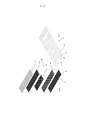
[012] Em outro aspecto, um compósito absorvente é revelado tendo um substrato não trançado volumoso, um tecido de topo ligado com o substrato não trançado volumoso, e uma camada de partículas superabsorventes (SAP) fixadas entre os mesmos. Além disso, adesivo fundido por calor é intercalado com o SAP para fixar mutuamente o SAP com o substrato não trançado volumoso e tecido de topo. O tecido de topo pode ser um trançado em modalidades preferidas.[012] In another aspect, an absorbent composite is disclosed having a bulky nonwoven substrate, a top fabric bonded with the bulky nonwoven substrate, and a layer of superabsorbent particles (SAP) affixed therebetween. In addition, heat melt adhesive is interspersed with the SAP to mutually secure the SAP with the bulky non-woven substrate and top fabric. The top fabric can be braided in preferred embodiments.
[013] Em ainda outro aspecto, é revelado um método para a fabricação de um compósito absorvente. O método implica transportar um primeiro substrato de um material não trançado, fornecer uma mistura de partículas superabsorventes (SAP) com partículas de adesivo de fusão por calor sobre o primeiro substrato transportado, e, como o primeiro substrato com a mistura é transportado, aplicar calor para o primeiro substrato, ativando deste modo as partículas de adesivo de fusão por calor e ligando o SAP com as partículas de fusão por calor e o primeiro substrato. Um segundo substrato é então aplicado no topo do primeiro substrato e o SAP ligado ao mesmo.[013] In yet another aspect, a method for manufacturing an absorbent composite is disclosed. The method entails transporting a first substrate of a non-woven material, providing a mixture of superabsorbent particles (SAP) with heat-melt adhesive particles onto the first transported substrate, and, as the first substrate with the mixture is transported, applying heat to the first substrate, thereby activating the heat melt adhesive particles and bonding the SAP with the heat melt particles and the first substrate. A second substrate is then applied on top of the first substrate and the SAP bonded thereto.
[014] Várias modalidades são divulgadas em que agregados de partículas absorventes são estrategicamente localizados e/ou constituídos entre uma camada de topo e uma camada de fundo, e em toda a extensão do compósito ou núcleo. Ao variar a posição dos agregados ou as restrições sobre os agregados, o desempenho e capacidades do compósito absorvente podem ser gerenciados ou influenciados. Em certas modalidades, os agregados de partículas absorventes são situados em recipientes ou bolsas. Em outras modalidades, o tamanho, espaçamento, arranjo, e/ou geometria ou forma dos recipientes ou bolsas são especificamente fornecidos para atingir certas propriedades de manuseamento de fluido de núcleo.[014] Several modalities are disclosed in which aggregates of absorbent particles are strategically located and/or constituted between a top layer and a bottom layer, and throughout the entirety of the composite or core. By varying the position of the aggregates or the restrictions on the aggregates, the performance and capacities of the absorbent composite can be managed or influenced. In certain embodiments, the absorbent particle aggregates are located in containers or pouches. In other embodiments, the size, spacing, arrangement, and/or geometry or shape of the containers or pouches are specifically provided to achieve certain core fluid handling properties.
[015] Em uma modalidade, um artigo absorvente descartável inclui um corpo de chassi definido por uma primeira margem de extremidade e uma segunda margem de extremidade afastada longitudinalmente da primeira margem de extremidade, as margens de extremidade definindo parcialmente regiões de cintura frontal e posterior que podem ser presas sobre uma cintura de um usuário. O artigo inclui ainda uma folha de topo, uma folha de fundo e um compósito absorvente disposto entre a folha de topo e a folha de fundo. A folha de topo e a folha de fundo definem margens longitudinais e laterais do corpo de chassi. O compósito absorvente inclui um primeiro tecido e um segundo tecido ligado ao primeiro tecido. Além disso, partículas absorventes são aderidas entre o primeiro e o segundo tecido, em que o primeiro tecido é intermitentemente anexado para o segundo tecido para definir uma pluralidade de recipientes situados entre o primeiro tecido e o segundo tecido e contendo um agregado de partículas absorventes. O compósito absorvente inclui regiões de recipientes de agregados de partículas absorventes incluindo uma região primária tendo recipientes com um primeiro tamanho e uma região secundária tendo uma pluralidade de recipientes de um segundo tamanho diferente do primeiro tamanho.[015] In one embodiment, a disposable absorbent article includes a chassis body defined by a first end margin and a second end margin spaced longitudinally from the first end margin, the end margins partially defining front and rear waist regions that can be fastened over a user's waist. The article further includes a top sheet, a back sheet and an absorbent composite disposed between the top sheet and the back sheet. The top sheet and the bottom sheet define the longitudinal and lateral edges of the chassis body. The absorbent composite includes a first fabric and a second fabric bonded to the first fabric. Furthermore, absorbent particles are adhered between the first and second fabrics, wherein the first fabric is intermittently attached to the second fabric to define a plurality of containers situated between the first fabric and the second fabric and containing an aggregate of absorbent particles. The absorbent composite includes container regions of aggregates of absorbent particles including a primary region having containers of a first size and a secondary region having a plurality of containers of a second size other than the first size.
[016] A presente invenção é de um compósito absorvente que, em algumas modalidades, não requer uma matriz absorvente e um novo método de fazer o compósito absorvente. O presente documento também divulga um artigo absorvente que incorpora o compósito absorvente. O compósito absorvente fornece um artigo absorvente que pode ser feito muito fino e flexível e, ao mesmo tempo, retendo SAP suficiente para fornecer capacidade de absorção suficiente e integridade seca e molhada (absorção uniforme). Embora a utilização do compósito absorvente em uma fralda seja descrita, um perito na arte poderia prontamente entender que um compósito absorvente feito de acordo com o processo da invenção pode ser utilizado em uma grande variedade de produtos absorventes.[016] The present invention is an absorbent composite that, in some embodiments, does not require an absorbent matrix and a new method of making the absorbent composite. The present document also discloses an absorbent article that incorporates the absorbent composite. The absorbent composite provides an absorbent article that can be made very thin and flexible while retaining enough SAP to provide sufficient absorbency and wet and dry integrity (uniform absorption). Although the use of the absorbent composite in a diaper is described, one skilled in the art would readily understand that an absorbent composite made in accordance with the process of the invention can be used in a wide variety of absorbent products.
[017] A presente invenção é também dirigida a um artigo absorvente melhorado incorporando o compósito absorvente.[017] The present invention is also directed to an improved absorbent article incorporating the absorbent composite.
[018] Em um exemplo, é descrito um método para fabricação de uma folha compósita, que compreende os passos de posicionar um primeiro tecido para receber partículas, depositar partículas no primeiro tecido, aplicar adesivo a um segundo tecido, posicionar o segundo tecido em relação ao primeiro tecido, e formar locais de ligação estendendo entre o primeiro e segundo tecido. O método pode ainda incluir um artigo em que as partículas compreendem partículas de SAP, partículas de cuidados da pele, partículas de absorção de odor, partículas de aglomerante, partículas de troca iônica, e as suas combinações. Ainda mais, o método pode incluir o passo de revestir as partículas com um material hidrofóbico.[018] In one example, a method for manufacturing a composite sheet is described, comprising the steps of positioning a first fabric to receive particles, depositing particles on the first fabric, applying adhesive to a second fabric, positioning the second fabric in relation to the first fabric, and form binding sites extending between the first and second fabric. The method can further include an article wherein the particles comprise SAP particles, skin care particles, odor absorbing particles, binder particles, ion exchange particles, and combinations thereof. Still further, the method may include the step of coating the particles with a hydrophobic material.
[019] O método pode incluir conformar o primeiro tecido a uma superfície. A superfície pode incluir recessos que formam bolsas ou recipientes no primeiro tecido quando ele é conformado à superfície.As partículas de SAP podem ser guiadas nas bolsas formadas no primeiro tecido.Sucção pode ser utilizada para conformar o primeiro tecido para a superfície. O adesivo aplicado ao segundo tecido pode ser aplicado em uma concentração suficiente para garantir uma quantidade eficaz de partículas secas. Essa concentração é geralmente compreendida entre 1 a 100 gramas por metro quadrado. Mais especificamente, o adesivo pode ser aplicado em uma concentração de entre 5 e 75 gramas por metro quadrado, ou ainda mais idealmente, entre 12 e 50 gramas por metro quadrado. O adesivo pode ser aplicado de um modo tal que a quantidade total de adesivo engatando partículas é entre 1 e 100 gramas por metro quadrado. O método da invenção pode incluir ainda um passo de aplicação de adesivo para o primeiro tecido antes das partículas serem depositadas no primeiro tecido.[019] The method may include conforming the first fabric to a surface. The surface can include recesses that form pockets or containers in the first fabric when it is shaped to the surface. The SAP particles can be guided into pockets formed in the first fabric. Suction can be used to shape the first fabric to the surface. The adhesive applied to the second fabric can be applied in a concentration sufficient to ensure an effective amount of dry particles. This concentration is generally between 1 to 100 grams per square meter. More specifically, the adhesive can be applied at a concentration of between 5 and 75 grams per square meter, or even more ideally, between 12 and 50 grams per square meter. The adhesive can be applied in such a way that the total amount of adhesive engaging particles is between 1 and 100 grams per square meter. The method of the invention may further include a step of applying adhesive to the first fabric before the particles are deposited on the first fabric.
[020] Os locais de ligação adequados para o método podem ser linhas de ligação, que podem ser contínuas ou descontínuas e poder definir bolsas ou outras formas e desenhos.Alternativamente, os locais de ligação podem ser pontos de ligação. Os locais de ligação podem ser posicionados relativamente a partículas e/ou dispostos de modo a impedir a migração de partícula de linha reta de mais do que 2 polegadas (5,08 cm).[020] The connection sites suitable for the method can be connection lines, which can be continuous or discontinuous and can define pockets or other shapes and designs. Alternatively, the connection sites can be connection points. Binding sites can be positioned relative to particles and/or arranged to prevent straight-line particle migration of more than 2 inches (5.08 cm).
[021] Em alternativa, o método envolve posicionar um primeiro tecido para receber partículas, posicionar partículas no primeiro tecido, fixar as partículas em relação ao primeiro tecido, posicionar um segundo tecido sobre as partículas, e formar locais de ligação que unem o primeiro tecido ao segundo tecido.Os locais de ligação podem ser pontos discretos espaçados para inibir a migração das partículas. Os locais de ligação também podem ser linhas de ligação espaçadas para inibir a migração de partículas, ou linhas de ligação que são conectadas para formar uma única linha de ligação. As linhas de ligação podem ser dispostas de modo a formar bolsas em que algumas das partículas são posicionadas. As partículas podem ser partículas de SAP, partículas de cuidados da pele, partículas de absorção de odor, partículas de aglomerante, partículas de troca iônica, e as suas combinações. As partículas podem ser fixadas ao primeiro tecido com adesivo, plástico térmico, ou suas combinações. Em adição a, ou em alternativa, as partículas podem ser fixadas ao segundo tecido com o adesivo, plástico térmico, ou suas combinações.Além disso, formas podem ser formadas no primeiro tecido para receber as partículas.[021] Alternatively, the method involves positioning a first tissue to receive particles, positioning particles in the first tissue, affixing the particles relative to the first tissue, positioning a second tissue over the particles, and forming binding sites that join the first tissue to the second tissue. Binding sites may be discrete points spaced apart to inhibit particle migration. Binding sites can also be binding lines spaced apart to inhibit particle migration, or binding lines that are connected to form a single binding line. The connecting lines can be arranged to form pockets in which some of the particles are positioned. The particles can be SAP particles, skin care particles, odor absorbing particles, binder particles, ion exchange particles, and combinations thereof. The particles can be attached to the first fabric with adhesive, thermal plastic, or combinations thereof. In addition to, or alternatively, the particles can be attached to the second fabric with the adhesive, thermal plastic, or combinations thereof. Furthermore, shapes can be formed on the first fabric to receive the particles.
[022] Um artigo absorvente descartável de acordo com a divulgação pode compreender uma folha de topo, uma folha de fundo e um núcleo absorvente disposto entre as mesmas, em que pelo menos uma porção de um de folha de fundo, folha de topo, e um núcleo absorvente. O núcleo absorvente é um compósito absorvente que compreende um primeiro tecido, um segundo tecido ligado ao primeiro tecido, e partículas aderidas entre o primeiro e segundo tecido. As partículas podem ser partículas de SAP, partículas de cuidados da pele, partículas de absorção de odor, partículas de aglomerante, partículas de troca iônica, e as suas combinações.[022] A disposable absorbent article according to the disclosure may comprise a topsheet, a bottomsheet and an absorbent core disposed therebetween, wherein at least a portion of a bottomsheet, topsheet, and an absorbent core. The absorbent core is an absorbent composite comprising a first fabric, a second fabric bonded to the first fabric, and particles adhered between the first and second fabric. The particles can be SAP particles, skin care particles, odor absorbing particles, binder particles, ion exchange particles, and combinations thereof.
[023] Em alternativa, uma camada absorvente pode ser fornecida que é suportada sobre a folha de fundo, de tal modo que uma seção da folha de fundo fornece o segundo tecido do compósito absorvente. A folha de fundo pode compreender ainda uma primeira camada de folha de fundo, uma segunda camada de folha de fundo e partículas de SAP em uma concentração de cerca de 20 gsm posicionadas entre as mesmas e a segunda camada de folha de fundo é um SMS tendo um peso básico no intervalo de cerca de 10 gsm a 60 gsm. A camada absorvente pode ser aderida entre o primeiro e segundo tecido com uma concentração de adesivo entre 1 e 100 gramas por metro quadrado. O primeiro tecido pode ser ligado ao segundo tecido em pontos discretos, pontos discretos podem definir bolsas. Além disso, o primeiro tecido pode ser ligado ao segundo tecido ao longo de uma pluralidade de linhas de ligação, estas linhas de ligação podem definir bolsas.[023] Alternatively, an absorbent layer can be provided that is supported on the backsheet, such that a section of the backsheet provides the second fabric of the absorbent composite. The bottom sheet may further comprise a first bottom sheet layer, a second bottom sheet layer and SAP particles in a concentration of about 20 gsm positioned therebetween and the second bottom sheet layer is an SMS having a basis weight in the range of about 10gsm to 60gsm. The absorbent layer can be adhered between the first and second fabrics with an adhesive concentration between 1 and 100 grams per square meter. The first fabric can be attached to the second fabric in discrete stitches, discrete stitches can define pockets. In addition, the first fabric may be attached to the second fabric along a plurality of tie lines, these tie lines may define pockets.
[024] O núcleo absorvente pode também compreender um primeiro tecido, um segundo tecido, locais de ligação em que o primeiro tecido é ligado ao segundo tecido; e uma camada absorvente de partículas aderidas entre o primeiro e segundo tecido.As partículas podem ser partículas de SAP e/ou outras partículas benéficas. A camada absorvente pode ser suportada por baixo de uma seção da folha de topo, de tal modo que a seção da folha de topo fornece o segundo tecido do compósito absorvente. A camada absorvente pode ser suportada sobre uma seção da folha de fundo, de modo que a seção de folha de fundo fornece o primeiro tecido do compósito absorvente.[024] The absorbent core may also comprise a first fabric, a second fabric, attachment sites where the first fabric is attached to the second fabric; and an absorbent layer of particles adhered between the first and second fabric. The particles can be SAP particles and/or other beneficial particles. The absorbent layer may be supported under a section of the topsheet such that the section of the topsheet provides the second fabric of the absorbent composite. The absorbent layer may be supported on a section of the bottom sheet so that the bottom sheet section provides the first fabric of the absorbent composite.
[025] Em algumas modalidades, o artigo absorvente descartável pode incluir uma concentração de partículas de SAP na camada absorvente de entre cerca de 50 e 650 gramas por metro quadrado. As partículas de SAP podem também ser revestidas com um material hidrofóbico para retardar a recepção inicial de líquido pelas partículas de SAP na camada absorvente. Os locais de ligação podem definir uma pluralidade de linhas contínuas que inibem o movimento das partículas de SAP da camada absorvente. As linhas contínuas podem ter uma forma de modo a formar bolsas entre o primeiro e segundo tecidos.Os locais de ligação podem definir uma pluralidade de linhas descontínuas que inibem o movimento das partículas de SAP da camada absorvente.As linhas descontínuas podem ser moldadas de modo a formar bolsas entre o primeiro e segundo tecido.[025] In some embodiments, the disposable absorbent article may include a concentration of SAP particles in the absorbent layer of between about 50 and 650 grams per square meter. The SAP particles can also be coated with a hydrophobic material to retard initial liquid uptake by the SAP particles in the absorbent layer. Binding sites can define a plurality of continuous lines that inhibit movement of the SAP particles from the absorbent layer. The solid lines can be shaped so as to form pockets between the first and second fabrics. The binding sites can define a plurality of broken lines that inhibit the movement of the SAP particles from the absorbent layer. to form pockets between the first and second fabric.
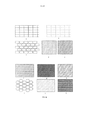
[026] Em ainda outra modalidade, as ligações podem ser posicionadas ao longo da periferia das bolsas de partículas. As ligações podem formar um padrão tal como espinha de peixe, camada de tijolos, círculos, triângulos, pontos, traços, retângulos, e suas combinações. A ainda outra modalidade pode também incluir partículas soltas posicionadas entre a primeira e segunda folhas.[026] In yet another modality, the connections can be positioned along the periphery of the pockets of particles. Links can form a pattern such as fishbone, brick layer, circles, triangles, dots, dashes, rectangles, and their combinations. Yet another embodiment can also include loose particles positioned between the first and second sheets.
[027] O precedente delineou bastante amplamente as características e vantagens técnicas da presente divulgação de modo que a descrição detalhada que segue possa ser melhor compreendida. Características e vantagens adicionais serão descritas aqui a seguir. Deve ser apreciado que as modalidades específicas divulgadas podem ser prontamente utilizadas como uma base para modificar ou conceber outras estruturas para realizar os mesmos propósitos. Deve também ser compreendido que tais construções equivalentes não se afastam da divulgação como estabelecido nas reivindicações anexas. As características que se acredita serem características da divulgação, tanto quanto à sua organização e método de operação, juntamente com outros objetivos e vantagens serão melhor compreendidas a partir da descrição seguinte quando considerada em ligação com as figuras anexas. Deve ser expressamente entendido, no entanto, que cada uma das figuras é fornecida para o propósito de ilustração e descrição e não pretende ser uma definição dos limites da presente invenção.Um artigo absorvente descartável de acordo com a divulgação pode compreender uma folha de topo, uma folha de fundo e um núcleo absorvente disposto entre as mesmas. O núcleo absorvente é um compósito absorvente que compreende um primeiro tecido, um segundo tecido ligado ao primeiro tecido e partículas fixadas entre o primeiro e segundo tecido. As partículas podem ser partículas de SAP, partículas de cuidados da pele, partículas de absorção de odor, partículas de aglomerante, partículas de troca iônica, as suas combinações, ou em modalidades preferenciais consistem de SAP.[027] The foregoing has outlined the technical features and advantages of the present disclosure quite broadly so that the detailed description that follows may be better understood. Additional features and benefits will be described here below. It should be appreciated that the specific modalities disclosed can be readily used as a basis for modifying or designing other structures to accomplish the same purposes. It is also to be understood that such equivalent constructions do not depart from the disclosure as set out in the appended claims. The characteristics believed to be characteristic of the disclosure, as far as its organization and method of operation, together with other objectives and advantages will be better understood from the following description when considered in connection with the attached figures. It is to be expressly understood, however, that each of the figures is provided for the purposes of illustration and description and is not intended as a definition of the limits of the present invention. A disposable absorbent article in accordance with the disclosure may comprise a top sheet, a backing sheet and an absorbent core disposed therebetween. The absorbent core is an absorbent composite comprising a first fabric, a second fabric bonded to the first fabric, and particles bonded between the first and second fabrics. The particles can be SAP particles, skin care particles, odor absorbing particles, binder particles, ion exchange particles, combinations thereof, or in preferred embodiments consist of SAP.
[028] Em alternativa, uma camada absorvente pode ser fornecida que é suportada sobre a folha de fundo, de tal modo que uma seção da folha de fundo fornece o segundo tecido do compósito absorvente. A folha de fundo pode compreender ainda uma primeira camada de folha de fundo, uma segunda camada de folha de fundo e partículas de SAP em uma concentração de cerca de 20 gsm posicionadas entre as mesmas e a segunda camada de folha de fundo é um SMS tendo um peso básico no intervalo de cerca de 10 gsm a 60 gsm. A camada absorvente pode ser aderida entre o primeiro e segundo tecido com uma concentração de adesivo entre 1 e 100 gramas por metro quadrado. O primeiro tecido pode ser ligado ao segundo tecido em pontos discretos, pontos discretos podem definir bolsas. Além disso, o primeiro tecido pode ser ligado ao segundo tecido ao longo de uma pluralidade de linhas de ligação, estas linhas de ligação podem definir bolsas.[028] Alternatively, an absorbent layer can be provided that is supported on the backsheet, such that a section of the backsheet provides the second fabric of the absorbent composite. The bottom sheet may further comprise a first bottom sheet layer, a second bottom sheet layer and SAP particles in a concentration of about 20 gsm positioned therebetween and the second bottom sheet layer is an SMS having a basis weight in the range of about 10gsm to 60gsm. The absorbent layer can be adhered between the first and second fabrics with an adhesive concentration between 1 and 100 grams per square meter. The first fabric can be attached to the second fabric in discrete stitches, discrete stitches can define pockets. In addition, the first fabric may be attached to the second fabric along a plurality of tie lines, these tie lines may define pockets.
[029] O núcleo absorvente pode também compreender um primeiro tecido, um segundo tecido, locais de ligação em que o primeiro tecido é ligado ao segundo tecido; e uma camada absorvente de partículas aderidas entre o primeiro e segundo tecido.As partículas podem ser partículas de SAP e/ou outras partículas benéficas. A camada absorvente pode ser suportada por baixo de uma seção da folha de topo, de tal modo que a seção da folha de topo fornece o segundo tecido do compósito absorvente. A camada absorvente pode ser suportada sobre uma seção da folha de fundo, de modo que a seção de folha de fundo fornece o primeiro tecido do compósito absorvente.[029] The absorbent core may also comprise a first fabric, a second fabric, attachment sites where the first fabric is attached to the second fabric; and an absorbent layer of particles adhered between the first and second fabric. The particles can be SAP particles and/or other beneficial particles. The absorbent layer may be supported under a section of the topsheet such that the section of the topsheet provides the second fabric of the absorbent composite. The absorbent layer may be supported on a section of the bottom sheet so that the bottom sheet section provides the first fabric of the absorbent composite.
[030] Em algumas modalidades, o artigo absorvente descartável pode incluir uma concentração de partículas de SAP na camada absorvente de entre cerca de 50 e 650 gramas por metro quadrado. As partículas de SAP podem também ser revestidas com um material hidrofóbico para retardar a recepção inicial de líquido pelas partículas de SAP na camada absorvente. Os locais de ligação podem definir uma pluralidade de linhas contínuas que inibem o movimento das partículas de SAP da camada absorvente.As linhas contínuas podem ter uma forma de modo a formar bolsas entre o primeiro e segundo tecidos.Os locais de ligação podem definir uma pluralidade de linhas descontínuas que inibem o movimento das partículas de SAP da camada absorvente.As linhas descontínuas podem ser moldadas de modo a formar bolsas entre o primeiro e segundo tecido.[030] In some embodiments, the disposable absorbent article may include a concentration of SAP particles in the absorbent layer of between about 50 and 650 grams per square meter. The SAP particles can also be coated with a hydrophobic material to retard initial liquid uptake by the SAP particles in the absorbent layer. The binding sites may define a plurality of continuous lines that inhibit movement of the SAP particles from the absorbent layer. The continuous lines may be shaped so as to form pockets between the first and second tissues. The binding sites may define a plurality of broken lines that inhibit the movement of the SAP particles from the absorbent layer. The broken lines can be shaped to form pockets between the first and second fabrics.
[031] Em ainda outra modalidade, as ligações podem ser posicionadas ao longo da periferia das bolsas de partículas. As ligações podem formar um padrão tal como espinha de peixe, camada de tijolos, círculos, triângulos, pontos, traços, retângulos, e suas combinações. A ainda outra modalidade pode também incluir partículas soltas posicionadas entre a primeira e segunda folhas.[031] In yet another embodiment, the connections can be positioned along the periphery of the particle pockets. Links can form a pattern such as fishbone, brick layer, circles, triangles, dots, dashes, rectangles, and their combinations. Yet another embodiment can also include loose particles positioned between the first and second sheets.
[032] O precedente delineou bastante amplamente as características e vantagens técnicas da presente divulgação, de modo que a descrição detalhada que segue possa ser melhor compreendida. Características e vantagens adicionais serão descritas aqui a seguir. Deve ser apreciado que as modalidades específicas divulgadas podem ser prontamente utilizadas como uma base para modificar ou conceber outras estruturas para realizar os mesmos propósitos. Deve também ser compreendido que tais construções equivalentes não se afastam da divulgação como estabelecido nas reivindicações anexas. As características que se acredita serem características da divulgação, tanto quanto à sua organização e método de operação, juntamente com outros objetivos e vantagens serão melhor compreendidos a partir da descrição seguinte quando considerada em ligação com as figuras anexas.Deve ser expressamente entendido, no entanto, que cada uma das figuras é fornecida para o propósito de ilustração e descrição e não pretende ser uma definição dos limites da presente invenção.[032] The foregoing has outlined the technical characteristics and advantages of the present disclosure quite broadly, so that the detailed description that follows may be better understood. Additional features and benefits will be described here below. It should be appreciated that the specific modalities disclosed can be readily used as a basis for modifying or designing other structures to accomplish the same purposes. It is also to be understood that such equivalent constructions do not depart from the disclosure as set out in the appended claims. The characteristics believed to be characteristic of the disclosure, as far as its organization and method of operation, together with other objectives and advantages will be better understood from the following description when considered in connection with the attached figures. It must be expressly understood, however , that each of the figures is provided for the purposes of illustration and description and is not intended as a definition of the limits of the present invention.
[033] Para uma compreensão mais completa da presente invenção, é feita agora referência à seguinte descrição tomada em conjunto com os desenhos anexos, nos quais: a Figura 1 é um diagrama esquemático de uma modalidade de um método de fazer um compósito absorvente utilizando rolos de calendário; a Figura 2 é um diagrama esquemático de uma outra modalidade de um método de fazer o compósito absorvente da invenção utilizando rolos de calendário; a Figura 3 é uma representação esquemática do método mostrado na Figura 1 com uma fonte de energia adicional; a Figura 4 é uma variação do método mostrado na Figura 1 que utiliza técnicas de ligação ultrassônica, em vez de rolos de calendário; a Figura 5 é uma variação do método mostrado na Figura 2 que utiliza técnicas de ligação ultrassônica em vez de rolos de calendário; a Figura 6 é uma ilustração de vários padrões de ligação potenciais que podem ser utilizados no método e artigo absorvente; a Figura 7 é uma ilustração de seção transversal de um bolsas formadas pelo método e utilizadas no artigo absorvente; a Figura 8 é uma vista em perspectiva de um artigo absorvente descartável que contém o compósito absorvente; a Figura 9 é uma vista plana de topo do artigo absorvente descartável da Figura 8 em uma condição estendida e plana; a Figura 10 é uma vista explodida do artigo descartável da Figura 8; a Figura 11 é uma vista de seção transversal parcial de um núcleo absorvente utilizando o compósito absorvente e empregado por um artigo absorvente; a Figura 12 é uma vista de seção transversal parcial de um núcleo absorvente utilizando uma modalidade alternativa do compósito absorvente da invenção e utilizado por um artigo absorvente alternativo; a Figura 13 é uma vista de seção transversal de um artigo absorvente empregando nas bainhas de perna um compósito absorvente; a Figura 14 é uma vista de seção transversal de um artigo absorvente empregando nas bainhas de perna um compósito absorvente saturado; as Figuras 15A-15D são representações simplificadas de um compósito absorvente de acordo com a presente invenção, com atenção particular a um arranjo de agregados de partículas absorventes por todo o compósito; a Figura 16A é uma ilustração simplificada de um sanduíche de SAP da arte anterior; a Figura 16B é uma ilustração simplificada de uma estrutura de SAP (sanduíche) de acordo com a presente invenção; as Figuras 17A-17D são ilustrações em seção transversal de bolsas e propriedades de fluido que caracterizam o arranjo de bolsas, em conformidade com a descrição simplificada; a Figura 18A é uma representação esquemática simplificada de um processo de fabricação de um compósito absorvente de acordo com a divulgação; as Figuras 18B-18C são ilustrações ou fotografias de componentes exemplares do processo descrito em relação à Figura 18A; a Figura 19 é uma vista de seção transversal simplificada representando um compósito absorvente de acordo com o processo da Figura 18A; as Figuras 20A são uma vista de seção transversal simplificada através de uma linha central lateral de um artigo absorvente descartável empregando um laminado de núcleo absorvente de acordo com uma modalidade preferida da divulgação; a Figura 20B é uma vista de seção transversal simplificada através de uma linha central longitudinal de um artigo absorvente descartável empregando um laminado de núcleo absorvente de acordo com uma modalidade preferida da divulgação; a Figura 20C é uma vista de seção transversal simplificada de um compósito absorvente no laminado de núcleo absorvente das Figuras 20A e 20B; a Figura 21 é uma vista explodida de um laminado de núcleo absorvente de acordo com uma modalidade da divulgação; as Figuras 22A-22C são vistas explodidas dos vários passos de fabricação do laminado na Figura 21; a Figura 23 é uma vista em perspectiva de topo de um laminado de núcleo absorvente estampado de acordo com uma modalidade da divulgação; a Figura 24 é uma vista plana de um laminado de núcleo absorvente exemplar utilizando pontos de ligação, de acordo com uma modalidade da divulgação; a Figura 25 é uma vista plana de um laminado de núcleo absorvente de acordo com uma modalidade alternativa da divulgação; a Figura 26 é uma vista explodida de um laminado de núcleo absorvente de acordo com uma modalidade alternativa da divulgação; a Figura 27 é uma ilustração simplificada de uma fase na fabricação de um laminado de núcleo absorvente de acordo com uma modalidade da divulgação; a Figura 28 é uma vista plana de um artigo absorvente descartável empregando um laminado de núcleo absorvente, de acordo com uma modalidade preferida da divulgação; a Figura 29 é uma ilustração simplificada em vista de seção transversal de um compósito absorvente de acordo com uma modalidade preferida da divulgação; e a Figura 30 é uma ilustração simplificada em vista de seção transversal parcial de um ponto de camada não trançado volumoso ligado em um compósito absorvente de acordo com a divulgação.[033] For a more complete understanding of the present invention, reference is now made to the following description taken in conjunction with the accompanying drawings, in which: Figure 1 is a schematic diagram of an embodiment of a method of making an absorbent composite using rollers of calendar; Figure 2 is a schematic diagram of another embodiment of a method of making the absorbent composite of the invention using calendar rolls; Figure 3 is a schematic representation of the method shown in Figure 1 with an additional power source; Figure 4 is a variation of the method shown in Figure 1 that uses ultrasonic bonding techniques instead of calendar rolls; Figure 5 is a variation of the method shown in Figure 2 which uses ultrasonic bonding techniques in place of calendar rolls; Figure 6 is an illustration of various potential binding patterns that can be used in the method and absorbent article; Figure 7 is a cross-sectional illustration of a pouches formed by the method and used in the absorbent article; Figure 8 is a perspective view of a disposable absorbent article containing the absorbent composite; Figure 9 is a top plan view of the disposable absorbent article of Figure 8 in an extended, flat condition; Figure 10 is an exploded view of the disposable article of Figure 8; Figure 11 is a partial cross-sectional view of an absorbent core utilizing the absorbent composite and employed by an absorbent article; Figure 12 is a partial cross-sectional view of an absorbent core utilizing an alternative embodiment of the absorbent composite of the invention and utilized by an alternative absorbent article; Figure 13 is a cross-sectional view of an absorbent article employing an absorbent composite in the leg cuffs; Figure 14 is a cross-sectional view of an absorbent article employing a saturated absorbent composite in the leg cuffs; Figures 15A-15D are simplified representations of an absorbent composite in accordance with the present invention, with particular attention to an array of absorbent particle aggregates throughout the composite; Figure 16A is a simplified illustration of a prior art SAP sandwich; Figure 16B is a simplified illustration of a SAP (sandwich) structure in accordance with the present invention; Figures 17A-17D are cross-sectional illustrations of pockets and fluid properties that characterize the pocket arrangement in accordance with the simplified description; Figure 18A is a simplified schematic representation of a process for manufacturing an absorbent composite in accordance with the disclosure; Figures 18B-18C are illustrations or photographs of exemplary components of the process described in relation to Figure 18A; Figure 19 is a simplified cross-sectional view showing an absorbent composite in accordance with the process of Figure 18A; Figure 20A is a simplified cross-sectional view through a lateral centerline of a disposable absorbent article employing an absorbent core laminate in accordance with a preferred embodiment of the disclosure; Figure 20B is a simplified cross-sectional view through a longitudinal centerline of a disposable absorbent article employing an absorbent core laminate in accordance with a preferred embodiment of the disclosure; Figure 20C is a simplified cross-sectional view of an absorbent composite in the absorbent core laminate of Figures 20A and 20B; Figure 21 is an exploded view of an absorbent core laminate in accordance with one embodiment of the disclosure; Figures 22A-22C are exploded views of the various manufacturing steps of the laminate in Figure 21; Figure 23 is a top perspective view of a patterned absorbent core laminate in accordance with one embodiment of the disclosure; Figure 24 is a plan view of an exemplary absorbent core laminate utilizing attachment points, in accordance with one embodiment of the disclosure; Figure 25 is a plan view of an absorbent core laminate in accordance with an alternative embodiment of the disclosure; Figure 26 is an exploded view of an absorbent core laminate in accordance with an alternative embodiment of the disclosure; Figure 27 is a simplified illustration of a step in manufacturing an absorbent core laminate in accordance with one embodiment of the disclosure; Figure 28 is a plan view of a disposable absorbent article employing an absorbent core laminate, in accordance with a preferred embodiment of the disclosure; Figure 29 is a simplified cross-sectional illustration of an absorbent composite in accordance with a preferred embodiment of the disclosure; and Figure 30 is a simplified illustration in partial cross-sectional view of a bulky non-woven layer stitch bonded into an absorbent composite in accordance with the disclosure.
[034] Após a análise da descrição detalhada e os desenhos anexos aqui fornecidos, será evidente para um vulgar perito na arte que um compósito absorvente feito de acordo com a presente invenção pode ser utilizado em artigos absorventes descartáveis, e mais particularmente, em artigos absorventes descartáveis, tais como fraldas, calças de treino e outros produtos para incontinência. Por conseguinte, a presente invenção não deve ser limitada às estruturas e processos especificamente descritos e ilustrados aqui, embora a seguinte descrição seja particularmente dirigida a um compósito absorvente que é utilizado em uma fralda descartável. O termo "artigo absorvente" ou "peça de vestuário absorvente" com o qual a presente invenção é associada inclui vários tipos de artigos descartáveis e peças de vestuário que são colocados contra ou na proximidade do corpo do usuário de modo a absorver e conter várias excreções corporais, fluidos corporais, ou fluidos biológicos.[034] Upon review of the detailed description and accompanying drawings provided herein, it will be apparent to one of ordinary skill in the art that an absorbent composite made in accordance with the present invention can be used in disposable absorbent articles, and more particularly, in absorbent articles disposable items such as diapers, workout pants and other incontinence products. Therefore, the present invention is not to be limited to the structures and processes specifically described and illustrated herein, although the following description is particularly directed to an absorbent composite that is used in a disposable diaper. The term "absorbent article" or "absorbent garment" with which the present invention is associated includes various types of disposable articles and garments that are placed against or in close proximity to the wearer's body so as to absorb and contain various excreta. bodily fluids, bodily fluids, or biological fluids.
[035] Talvez para obter uma melhor compreensão e apreciação das contribuições e melhorias particulares que são introduzidas na presente divulgação, pode ser feita referência em primeiro lugar às melhorias anteriormente divulgadas na Patente No. US 8,148,598.Estas melhorias anteriores são descritas em relação às Figuras 1-14. Alguns dos ensinamentos ou sugestões nela podem, além de servir como base de conhecimentos na arte, traduzir-se em certas modalidades específicas da presente invenção (que se tornarão evidentes para um perito na especialidade relevante, dada a presente divulgação).[035] Perhaps to gain a better understanding and appreciation of the particular contributions and improvements that are made in the present disclosure, reference may be made first to the improvements previously disclosed in US Patent No. 8,148,598. These prior improvements are described in relation to the Figures 1-14. Some of the teachings or suggestions therein may, in addition to serving as a knowledge base in the art, translate into certain specific embodiments of the present invention (which will become apparent to one of skill in the relevant art given the present disclosure).
[036] Na Figura 1, um tecido 125 é mostrado como é distribuído a partir do rolo 120 e transportado ao longo de uma linha de produção sobre uma correia transportadora 100. O tecido 125 pode ser material plástico térmico que pode ser um trançado, não trançado, película, ou uma combinação dos mesmos. O tecido 125 é preso à correia transportadora 100 por um sistema de vácuo 110. O sistema de vácuo 110 serve para confirmar o tecido 125 para a correia transportadora 100.[036] In Figure 1, a
[037] Em uma modalidade, a superfície da correia transportadora 100 tem porções rebaixadas que formam copos no tecido 125 como o tecido é puxado contra a superfície da correia transportadora 100. A superfície da correia transportadora 100 não é limitada a construções que formam copos no tecido, mas, em vez disso, pode ser configurada com um número de diferentes formas e tamanhos de superfície. Exemplos incluem cristas, formas elevadas e orifícios.Além disso, as formas de superfície podem ser distribuídas uniformemente ou não uniformemente em toda a largura e comprimento da correia transportadora.Alternativamente, a correia transportadora 100 pode ser plana. Em aplicações em que a correia transportadora 100 tem orifícios ou outras construções semelhantes, a profundidade das bolsas formadas no tecido 125 pode ser variada pela força do sistema de vácuo 110, a elasticidade do tecido 125, ou uma combinação dos mesmos. Além disso, o calor pode ser usado para aumentar a elasticidade do tecido 125 como o tecido é puxado contra a superfície da correia transportadora 100. O calor pode ser aplicado ao tecido por meio de uma correia transportadora aquecida ou qualquer outro meio conhecido na arte. O vácuo 110 pode ser aplicado uniformemente em toda a superfície da correia transportadora 100 ou em locais selecionados. Por exemplo, em uma configuração na qual a superfície da correia transportadora 100 tem depressões, vácuo pode ser aplicado apenas nas depressões.[037] In one embodiment, the surface of the
[038] As partículas de SAP 135 são, então, depositadas sobre o tecido 125 por distribuidor de SAP 130. O distribuidor de SAP 130 pode ser configurado para posicionar partículas de SAP na sua posição desejada no primeiro tecido ou pode ser configurado simplesmente para depositar partículas de SAP no primeiro tecido, em que as partículas de SAP são posicionadas por outros meios. Um perito na arte compreende que vários distribuidores de SAP 130 podem ser utilizados. As partículas de SAP 135 podem ser depositadas, posicionadas, ou ambas no tecido 125 pelo vento ou por outros métodos conhecidos. Alternativamente, o transportador mostrado na Figura 1 pode ser invertido de modo que o sistema de vácuo 110 aplica sucção a partir de cima. Em uma tal configuração, o tecido 125 é transportado ao longo de um fornecimento de partículas de SAP 135 e as partículas de SAP são mantidas sobre a superfície do tecido 125 por um sistema de vácuo 10. Em modalidades alternativas, o distribuidor de SAP 130 pode incluir partículas de cuidados da pele, tais como resinas de troca iônica, desodorizantes, agentes antimicrobianos, partículas de ligante, ou outras partículas benéficas. Além disso, embora a modalidade preferida seja dirigida a partículas de SAP, os métodos descritos aqui podem ser utilizados com qualquer combinação das partículas acima referenciadas, incluindo combinações que não incluem SAP. Alternativamente, distribuidores separados vantajosamente posicionados ao longo da linha de produção (não mostrada) podem ser usados para depositar diferentes tipos de partículas, tais como, por exemplo, partículas de cuidados da pele.[038] The
[039] As partículas de SAP 135 são posicionadas e concentradas no tecido 125 de acordo com uma série de métodos alternativos. Em uma modalidade, o sistema de vácuo 110 e o tecido 125 podem ser configurados para permitir o sistema de vácuo 110 puxar as partículas de SAP 135 contra a superfície do tecido 125 uniformemente ou em áreas específicas. Em uma outra modalidade, a forma do tecido 125 guia partículas de SAP 135 para posição. Por exemplo, quando o tecido 125 é formado de modo a formar bolsas, as partículas de SAP 135 rolam para as bolsas como um resultado do sistema de vácuo 110, a vibração da correia transportadora, o vento, o ângulo da correia transportadora, ou as suas combinações. Alternativamente, o distribuidor (s) de SAP 130 pode ser posicionado e controlado para dispensar partículas de SAP 135 estrategicamente ao longo da superfície de tecido 125, este posicionamento estratégico inclui, mas não é limitado a alinhamento ou desalinhamento com a direção de máquina, deslocamento, ou aleatoriamente. Além disso, o SAP pode ser posicionado de tal modo que existem zonas sem partículas de SAP. Mais ainda, as partículas de SAP podem ser posicionadas utilizando adesivo, tal como por aplicar adesivo a locais específicos sobre uma superfície, depositar partículas de SAP sobre a superfície. Mais ainda, as partículas de SAP podem ser colocadas em ambos os tecidos 125 e 155.[039] The
[040] Uma vez que as partículas de SAP foram depositadas e posicionadas no tecido 125, um segundo tecido 155 é introduzido na linha de produção a partir de rolo 150. O segundo tecido 155 pode ser selecionado a partir de uma variedade de materiais incluindo material fiado-ligado termoplástico ou trançado semelhante ou material não trançado, película ou combinações destes.[040] Once the SAP particles have been deposited and positioned on the
[041] O adesivo 145 é aplicado às partículas de SAP 135 em um certo número de maneiras.A Figura 1 mostra o adesivo 145 aplicado ao tecido 155. Em alternativa, o adesivo 145 pode ser aplicado ao tecido 125 e partículas de SAP 135, tecido 125 antes das partículas de SAP 135 serem depositadas no tecido 125, ou diretamente às partículas de SAP antes de serem depositadas no tecido 125. Em ainda uma outra modalidade, o adesivo 145 é aplicado no ponto em que tecidos 125 e 155 são unidos em conjunto. Em ainda outra modalidade, várias camadas de adesivo são aplicadas. Por exemplo, o adesivo 145 pode ser aplicado ao tecido 125 antes das partículas de SAP 135 serem depositadas, para as partículas de SAP 135 depois de terem sido posicionadas, para o tecido 155, ou uma combinação dos mesmos. Como alternativa ou em adição às modalidades acima, as partículas de ligante podem ser misturadas com as partículas de SAP 135. Além disso, o adesivo pode ser aplicado uniformemente, aleatoriamente, ou em um determinado padrão, dependendo das propriedades absorventes desejadas do compósito acabado.[041] Adhesive 145 is applied to
[042] O adesivo é aplicado de acordo com um certo número de métodos conhecidos dos especialistas na técnica. Por exemplo, o adesivo pode ser pulverizado, laminado, ou fiado sobre a superfície de tecido 155. O adesivo pode ser hidrofóbico, hidrofílico, biodegradável, bioderivado, ou suas combinações. O adesivo preferido é hidrofóbico. A concentração de adesivo em um revestimento varia entre 1 e 100 gramas por metro quadrado ("GSM").Otimamente, a concentração situa-se entre 5 e 75 GSM.Em uma modalidade preferida, a concentração é entre 12 e 50 GSM.Além disso, o adesivo deve ser aplicado suficiente para cobrir, pelo menos, 25% da área alvo.[042] The adhesive is applied according to a number of methods known to those skilled in the art. For example, the adhesive can be sprayed, laminated, or spun onto
[043] Tecidos 125 e 155 são, então, ligados uns aos outros.A Figura 1 mostra um sistema de ligação térmica em que rolos de calendário 160 e 170 são usados. No entanto, outros sistemas/métodos de ligação podem ser usados. Por exemplo, o sistema de ligação ultrassônico das Figuras 4 e 5 pode ser usado. Adesivo 145 retém as partículas de SAP 135 em uma posição relativamente fixa no que diz respeito aos tecidos durante o processo de ligação e subsequente ao processo de ligação. O padrão de ligação pode ser alinhado com a distribuição das partículas de SAP 135. Alternativamente, o padrão de ligação pode não ser alinhado com a distribuição das partículas de SAP 135. Em tais modalidades, o equipamento de ligação pode ser adaptado para deslocar as partículas de SAP 135 de lado antes da ligação ou para ligar através das partículas de SAP 135. Estas modalidades eliminam a necessidade de sincronizar os pontos de ligação com a distribuição de partículas de SAP.[043]
[044] Tecidos 155 e 125 são mostrados como dois materiais. No entanto, um especialista na técnica entende que os tecidos podem, na verdade, ser parte do mesmo material. Em tal configuração, o tecido unitário é dobrado para cobrir as partículas de SAP. Em alternativa, as bordas de tecido 125 podem ser dobradas antes de aplicar o segundo tecido 155. Em modalidades em que tecidos 125 e 155 são separados, tecidos 125 e 155 podem ser o mesmo ou um material diferente. Além disso, tecido 155 pode ser dimensionado para cobrir áreas específicas, tais como a seção central, de tecido 125.[044]
[045] Uma vez que os tecidos foram ligados entre si, o compósito absorvente 195 é coletado em rebobinador 200.[045] Once the tissues have been bonded together, the
[046] Em um método ilustrado na Figura 2, o tecido 125 é transportado ao longo da correia transportadora 100. Conforme tecido 125 é transportado ao longo da correia transportadora 100, uma fina camada de adesivo 145 é aplicada ao tecido 125. Tal como acontece com o método da Figura 1, o adesivo pode ser aplicado uniformemente, aleatoriamente, ou em um determinado padrão, dependendo das propriedades absorventes desejadas do compósito acabado. Embora o adesivo 145 seja mostrado para ser aplicado antes das partículas de SAP 135 serem depositadas, modalidades alternativas são previstas. Por exemplo, o adesivo pode ser aplicado de acordo com as modalidades descritas em relação à Figura 1.[046] In a method illustrated in Figure 2,
[047] Após a aplicação do adesivo, partículas de SAP 135 são depositadas e posicionadas no tecido 125. As partículas de SAP 135 podem ser depositadas diretamente no tecido 125, como mostrado na Figura 2, ou indiretamente, tal como por vento soprando partículas de SAP em tecido 125. O peso das partículas de SAP ajuda em fixar o tecido 125 para a correia transportadora 100. Além disso, as partículas de SAP podem ser posicionadas de um modo semelhante ao descrito para a Figura 1.[047] After application of the adhesive,
[048] Um segundo tecido 155 é então introduzido na linha de produção a partir de rolo 150. O segundo tecido é posicionado para cobrir as partículas de SAP 135. O adesivo 145 impede que as partículas de SAP se movam livremente entre os dois tecidos. A construção ensanduichada resultante é então transportada para os rolos de calendário para a ligação térmica.Conforme descrito em relação à Figura 1, o padrão de ligação pode ser alinhado ou não alinhado com as partículas de SAP 135. O compósito absorvente 195 é então recolhido por rebobinador 200. Tal como descrito em relação à Figura 1, tecidos 125 e 155 podem ser parte de uma única folha. Além disso, os tecidos podem ser dobrados no modo descrito por Figura 1. Em outra modalidade, o tecido 125 pode ser revestido com adesivo e pressionado em um fornecimento de partículas de SAP.[048] A
[049] A Figura 3 é semelhante às Figura 1 e 2, exceto que uma fonte de energia 900, tais como um gerador de microondas ou forno, é posicionada ao longo da linha de montagem. A fonte de energia aplica calor ou radiação 910 que pode ser utilizado para derreter ligante plástico térmico.A quantidade de calor pode também ser regulada para derreter tipos específicos de partículas ou fibras, seções específicas dos tecidos, ou apenas as camadas exteriores das partículas/ligante.[049] Figure 3 is similar to Figures 1 and 2, except that a 900 power source, such as a microwave generator or oven, is positioned along the assembly line. The energy source applies heat or
[050] As Figuras 4 e 5 são semelhantes às Figuras 1 e 2, exceto que os tecidos são ligados em conjunto utilizando ligações ultrassônicas. As Figuras 4 e 5 mostram um sistema de ligação ultrassônico (210a e 210b). É prontamente entendido que as Figuras 1-5 mostram diferentes modalidades do novo método e que os aspectos dos vários métodos podem ser combinados vantajosamente dependendo da necessidade. Importante para todas as combinações, no entanto, é a quantidade de adesivo 145, partículas de ligante, ou suas combinações aplicadas às partículas de SAP 135 e a resistência das ligações. Como notado no que diz respeito à Figura 1, a concentração ótima de adesivo é entre 12 e 50 GSM, embora outras concentrações sejam aceitáveis. Em todas as modalidades, é importante que a concentração de adesivo 145 seja suficientemente elevada para inibir a migração das partículas de SAP 135. A concentração não deve ser tão elevada, no entanto, que reveste as partículas de SAP 135 e reduz o inchamento de SAP. O adesivo deve apenas inibir a migração de partículas de SAP suficientes 135 para assegurar a absorção uniforme. Embora não esteja representado, um perito na arte entende que a fonte de energia 900 mostrada na Figura 3 também pode ser aplicada nas configurações mostradas nas Figuras 2, 4 e 5.[050] Figures 4 and 5 are similar to Figures 1 and 2, except that the tissues are connected together using ultrasonic connections. Figures 4 and 5 show an ultrasonic bonding system (210a and 210b). It is readily understood that Figures 1-5 show different embodiments of the new method and that aspects of the various methods can be advantageously combined depending on the need. Important for all combinations, however, is the amount of adhesive 145, binder particles, or combinations thereof applied to the
[051] As Figuras 6 (a) a (q) mostram vários padrões de ligação contemplados pelo método.Os padrões de ligação podem envolver completamente uma área, parcialmente envolver uma área, ou fornecer zonas de ligação locais.As linhas e pontos indicam os locais de ligação.As linhas sólidas representam linhas de ligação. As linhas de ligação podem formar formas abertas ou formas fechadas, tais como podem ser encontradas nos exemplos (a) e (c), que representam linhas de ligação contínuas que envolvem completamente bolsas de partículas de SAP 135 ou, tal como no exemplo (g), regiões distintas separadas do compósito absorvente. As linhas tracejadas, tal como pode ser encontrado em exemplos (b) e (m), são padrões de ligação descontínuos que não envolvem completamente bolsas de partículas de SAP 135. Nestas configurações, a migração das partículas de SAP secas é inibida pelo adesivo e padrões de ligação contínuos ou descontínuos.Padrões de ligação descontínuos podem ser substituídos por padrões de ligação contínuos e vice-versa.Além disso, embora a Figura 6 mostre tanto padrões de ligação contínuos ou descontínuos, combinações de padrões de ligação descontínuos e contínuos podem ser utilizadas.[051] Figures 6(a) to (q) show various bonding patterns contemplated by the method. Bonding patterns can completely enclose an area, partially enclose an area, or provide local bonding zones. The lines and dots indicate the binding sites. Solid lines represent binding lines. The bond lines can form open shapes or closed shapes, such as can be found in examples (a) and (c), which represent continuous bond lines that completely enclose pockets of
[052] A Figura 7 mostra uma seção transversal parcial de um compósito absorvente 195. A Figura 7 mostra como as ligações 192 podem atuar para separar bolsas de partículas de SAP 135. Como notado no que diz respeito ao padrão de ligação, as partículas de SAP 135 podem ser inteiramente envolvidas em bolsas definidas pelo padrão de ligação, parcialmente envolvidas em bolsas definidas pelo padrão de ligação ou apenas inibidas pelo padrão de ligação. Inibida neste contexto significa que as partículas de SAP 135 não podem mover diretamente a partir de uma área do núcleo para outra área, mas em vez disso, precisam mover em torno de locais de ligação.[052] Figure 7 shows a partial cross-section of an
[053] Em particular, várias funções ou propriedades vantajosas são obtidas no compósito absorvente por variar a quantidade de partículas de SAP, o tipo e número de tecidos utilizados, e variáveis de construção, tais como, a relação de SAP para adesivo, e aplicar o compósito absorvente em vários locais do artigo. Tais técnicas de fabricação e projeto podem ser incorporadas em modelos estruturais e métodos da presente revelação.[053] In particular, several advantageous functions or properties are obtained in the absorbent composite by varying the amount of SAP particles, the type and number of fabrics used, and construction variables such as the SAP to adhesive ratio, and applying the absorbent composite at various locations on the article. Such fabrication and design techniques can be incorporated into the structural models and methods of the present disclosure.
[054] Além disso, um perito na arte compreende que o processo para construção de um único compósito absorvente descrito acima pode ser modificado para produzir um compósito absorvente laminado múltiplo. Em estruturas que compreendem múltiplas camadas, as camadas podem ser folhas de compósito absorvente 195 que são laminadas em conjunto para formar uma estrutura única ou alternando camadas de tecido e partículas de SAP 135 que formam uma única estrutura. Um especialista na técnica entende que as camadas alternadas podem ser alcançadas por aplicar adesivo à parte superior de tecido 155 (Figura 1), aplicar uma segunda camada de partículas de SAP 135, e um terceiro tecido (não mostrado). Do mesmo modo, camadas adicionais podem ser adicionadas, limitado apenas pela espessura máxima adequada para o processo de ligação.[054] Furthermore, one skilled in the art understands that the process for constructing a single absorbent composite described above can be modified to produce a multiple laminated absorbent composite. In structures that comprise multiple layers, the layers can be absorbent
[055] As partículas de SAP 135 podem ser revestidas com um material hidrofóbico miscível. O revestimento atua como uma barreira ou membrana que inicialmente retarda a absorção de líquido, poupando assim a capacidade de SAP para descargas adicionais ou secundárias. A este respeito, o revestimento equilibra as taxas de absorção entre descargas. Nos processos mostrados nas Figuras 1 a 5, o revestimento pode ser aplicado antes do adesivo 145 ser aplicado, depois do adesivo 145 ser aplicado, ou ao mesmo tempo. Alternativamente, o adesivo pode ser misturado com o material de revestimento.[055]
[056] Em um exemplo, uma fina camada de óleo mineral é aplicada sobre as partículas de SAP 135. O revestimento retarda a absorção inicial pelas partículas de SAP e permite mais tempo para o líquido espalhar no artigo. De preferência, o óleo mineral é aplicado em uma concentração de cerca de 0,00001 gramas por grama de SAP a cerca de 0,1 gramas por grama de SAP (dependendo do desenho particular do produto). Alternativamente, o óleo mineral pode ser aplicado em zonas alvo específicas. Desta forma, o líquido recebido inicialmente é encorajado a espalhar para áreas não revestidas antes das áreas revestidas serem ativadas e começarem a inchar.[056] In one example, a thin layer of mineral oil is applied over the
[057] Um compósito absorvente fabricado pelo processo acima descrito pode ser utilizado para um artigo absorvente descartável ou como um ou mais dos componentes de um artigo absorvente descartável. Os componentes de um artigo absorvente incluem a folha de fundo, folha de topo, núcleo absorvente, paredes de contenção ou bainhas (incluindo pregas de perna), folha de fundo/compósito de núcleo absorvente, folha de topo/compósito absorvente, e combinações destes. Tais construções são descritas abaixo em mais detalhe.[057] An absorbent composite manufactured by the process described above can be used for a disposable absorbent article or as one or more of the components of a disposable absorbent article. Components of an absorbent article include the backsheet, topsheet, absorbent core, retaining walls or hems (including leg pleats), backsheet/absorbent core composite, topsheet/absorbent composite, and combinations thereof . Such constructions are described in more detail below.
[058] A Figura 8 é uma vista em perspectiva de um artigo absorvente descartável sob a forma de uma fralda 10. Fralda 10 compreende uma folha de topo 50, uma folha de fundo 60, e um núcleo absorvente (não mostrado).A fralda compreende ainda bainhas de barreira verticais 34 estendendo longitudinalmente ao longo da fralda e são elastificadas para estarem em conformidade com as nádegas do usuário. Além disso, a fralda inclui uma banda elástica 52 e fixadores 26. Elemento 26, em uso, estende para e engata na extremidade oposta correspondente da fralda para fixar a fralda em torno do usuário.[058] Figure 8 is a perspective view of a disposable absorbent article in the form of a diaper 10. Diaper 10 comprises a
[059] A Figura 9 ilustra uma estrutura de trama compósita da fralda 10 da Figura 8 em uma configuração geralmente plana e desdobrada. Como será explicado mais adiante, a estrutura de trama pode ser subsequentemente cortada, dobrada, fechada, soldada e/ou de outro modo manipulada de modo a formar uma fralda descartável 10 em uma forma final ou finalizada. Para facilitar a descrição da fralda 10, a descrição refere-se a um eixo estendendo longitudinalmente A-A, um eixo central estendendo lateralmente B-B, um par de bordas laterais estendendo longitudinalmente 90, e um par de bordas de extremidade 92 estendendo entre as bordas laterais 90. Ao longo do eixo longitudinal A-A, a fralda 10 inclui uma primeira região de extremidade ou região de cintura frontal 12, uma segunda região de extremidade ou região de cintura posterior 14, e uma área da virilha 16 disposta entre as mesmas. Cada da região de cintura frontal e posterior 12, 14 é caracterizada por um par de regiões de orelha ou orelhas 18, que são localizadas em ambos os lados de uma porção central do corpo 20 e estendem lateralmente a partir das bordas laterais 90. Uma estrutura de fixação 26 (por exemplo, um fixador de fita convencional) é afixada a cada uma das orelhas 18 ao longo da região de cintura posterior 14 da fralda 10.[059] Figure 9 illustrates a composite weft structure of the diaper 10 of Figure 8 in a generally flat and unfolded configuration. As will be explained further below, the weft structure may subsequently be cut, folded, closed, welded and/or otherwise manipulated to form a disposable diaper 10 in a final or finished shape. To facilitate the description of the diaper 10, the description refers to a longitudinally extending axis AA, a laterally extending central axis BB, a pair of longitudinally extending side edges 90, and a pair of end edges 92 extending between the side edges 90 Along the longitudinal axis AA, the diaper 10 includes a first end region or
[060] Quando a fralda 10 é usada em torno da cintura, a região de cintura frontal 12 é montada adjacente à região de cintura frontal do usuário, a região de cintura posterior 14 é montada adjacente à região de cintura posterior, e a área da virilha 16 se encaixa sobre e por baixo da área da virilha. Para fixar corretamente a fralda 10 no usuário, as orelhas 18 da região de cintura posterior 14 são trazidas em torno da cintura do usuário e em direção à frente e em alinhamento com as orelhas 18 da região de cintura frontal 12. A superfície de fixação pode ser localizada em ou fornecida pela superfície interior ou exterior da região de cintura frontal 12. Em alternativa, os fixadores 26 podem ser localizados nas orelhas 18 da região de cintura frontal 12 e feitos anexáveis para as orelhas 18 da região de cintura posterior 14.[060] When the diaper 10 is worn around the waist, the
[061] A Figura 10 é uma vista explodida da fralda da Figura 8 e 9.Uma estrutura de fralda adequada emprega tipicamente pelo menos três camadas.Estas três camadas incluem uma folha de fundo 60, um núcleo absorvente 46, e uma folha de topo 50. A estrutura de fralda pode ou não conter um par de paredes de confinamento ou bainhas de perna 34 dispostas no sentido ascendente a partir da folha de topo 50 e preferivelmente pelo menos equipada com um ou mais membros elásticos longitudinalmente espaçados 38. Será mostrado abaixo que qualquer um destes elementos de fralda ou uma combinação destes elementos podem ser construídos com ou utilizando o compósito absorvente 195.Além disso, uma camada de aquisição 48 pode ser adicionada para melhorar o desempenho.[061] Figure 10 is an exploded view of the diaper of Figure 8 and 9. A suitable diaper structure typically employs at least three layers. These three layers include a
[062] Como mencionado acima, a fralda 10 emprega uma folha de fundo 60 que cobre o núcleo 46 e de preferência estende para além do núcleo 46 em direção às bordas laterais 90 e bordas de extremidade 92 da fralda 10. Em um aspecto da invenção, a folha de fundo 60 é construída a partir de uma folha de material de camada única de compósito absorvente 195. Em uma tal configuração, o tecido 125 é posicionado como uma superfície exterior da folha de fundo 60.[062] As mentioned above, the diaper 10 employs a
[063] Além disso, uma estrutura alternativa poderia ser usada para bloqueio de gel. Para uma aplicação utilizando o bloqueio de gel, uma folha de fundo do artigo absorvente descartável da invenção é relativamente fina e fornece maior flexibilidade. Quando seca, a folha de fundo é respirável e suave, mas ao ser umedecida, uma camada bloqueada fina de gel é formada (isto é, na superfície interior da folha de fundo), o que torna a folha de fundo substancialmente impermeável a líquidos. A camada bloqueada de gel é formada por expansão das partículas de SAP 135.[063] Furthermore, an alternative structure could be used for gel blocking. For an application using gel blocking, a bottom sheet of the disposable absorbent article of the invention is relatively thin and provides greater flexibility. When dry, the bottom sheet is breathable and soft, but upon being moistened, a thin, interlocking layer of gel is formed (i.e., on the inner surface of the bottom sheet), which makes the bottom sheet substantially impervious to liquids. The blocked gel layer is formed by expansion of the
[064] Do mesmo modo, o compósito absorvente 195 pode ser utilizado com ou como a folha de topo de uma peça de vestuário absorvente. A folha de topo 50 é, de preferência, suave, complacente, exibe boa capacidade de choque e uma tendência reduzida para umedecer a partir de um material permeável a líquidos.A folha de topo 50 é colocada em estreita proximidade com a pele do usuário quando a fralda 10 é vestida. Deste modo, tal folha de topo 50 permite descargas corporais penetrarem rapidamente de modo a fluir em direção ao núcleo 46 de forma mais rápida, mas não permitindo que tais descargas fluam de volta através da folha de topo 50. A folha de topo 50 pode ser construída a partir de qualquer um de um amplo intervalo de materiais hidrofílicos permeáveis a líquidos e vapor. A superfície (s) da folha de topo pode ser tratada com um surfactante, de modo a facilitar a transferência do líquido através da mesma, em especial em uma região ou área central da folha de topo situada sobre o núcleo e uma superfície interior do núcleo. A folha de topo pode também ser revestida com uma substância com propriedades de redução de prurido ou prevenção de prurido (por exemplo, de vera).[064] Likewise, the
[065] Em um exemplo, a folha de topo 50 é formada a partir de um compósito absorvente 195 que cobre substancialmente toda a área do artigo absorvente descartável 10, incluindo substancialmente toda a região de cintura frontal 12, região de cintura posterior 14, e a área da virilha 16. Além disso, a camada de orelha da região interior 18 é formada a partir do mesmo material de folha de topo única e, portanto, pode ser referida como sendo unitária com a folha de topo 50 para formar extensões laterais do material de folha de topo. Alternativamente, a folha de topo 50 pode ser formada a partir de vários materiais diferentes que variam ao longo da largura da folha de topo 50. Tal concepção de peça múltipla permite criação de propriedades preferidas e diferentes zonas da folha de topo.[065] In one example, the
[066] Em adição a ou como uma alternativa aos exemplos anteriores, o núcleo absorvente do artigo absorvente descartável pode ser construído a partir do compósito absorvente 195, camadas laminadas de compósito absorvente 195 (não mostradas) ou de várias camadas de partículas de SAP 135 e tecido. As Figuras 11 e 12 ilustram vistas de seção transversal de camadas alternadas de partículas de SAP 135 e tecido que formam um compósito absorvente de multicamadas 700 e 900, respectivamente. Como se mostra nestes desenhos, o núcleo 46 pode ser constituído por camadas distintas de partículas de SAP 135 (710 e 910). As camadas podem ser uniformes ou não uniformes, consoante a aplicação pretendida. No compósito absorvente não uniforme de múltiplas camadas 900, a concentração de partículas de SAP 135 pode variar dentro de uma dada camada, entre camadas, ou suas combinações.[066] In addition to or as an alternative to the above examples, the absorbent core of the disposable absorbent article can be constructed from
[067] A Figura 11 representa uma estrutura de compósito 700 em que camadas de partículas de SAP 710 e camadas de tecido 720 são alternadas para formar a estrutura de compósito completada 700. O projeto em camadas pode também ser construído por ligação em conjunto de folhas de compósito absorvente, dobrando uma folha unitária de compósito absorvente, ou construindo compósitos absorventes com camadas múltiplas durante o processo de fabricação. Em aplicações dobradas, a dobra de compósito pode ser uma dobra C, dobra Z, dobra V, dobra W ou suas combinações. Além disso, as dobras podem ser abertas, fechadas, ou de sobreposição.[067] Figure 11 represents a
[068] A Figura 12 descreve compósitos absorventes multicamadas 900. Como mostrado na Figura 12, áreas de altas concentrações de partículas de SAP 910 podem ser posicionadas estrategicamente para fornecer capacidade de absorção adicional em regiões específicas, tais como a virilha de um artigo absorvente. Um especialista na técnica entende que as regiões de concentração elevada podem ser deslocadas para controlar a quantidade e a direção de penetração do líquido. Além disso, a camada com regiões de elevadas concentrações pode ser combinada com camadas de camadas substancialmente uniformes. Em alternativa, as regiões de alta concentração de SAP podem ser formadas pelo posicionamento de várias camadas de núcleo absorvente.[068] Figure 12 depicts 900 multilayer absorbent composites. As shown in Figure 12, areas of high concentrations of
[069] O núcleo pode ser configurado para estender substancialmente todo o comprimento e/ou largura do artigo absorvente descartável. De preferência, no entanto, o núcleo é disposto ou é de outra forma concentrado na área da virilha do artigo. Em várias modalidades, o núcleo estende para as bordas do artigo e as partículas de SAP 135 são concentradas na área da virilha ou outra região alvo do artigo. Em ainda outra modalidade, as partículas podem ser uma combinação de partículas de SAP, partículas de cuidados da pele, tais como resinas de troca iônica, desodorizantes, agentes antimicrobianos, partículas de ligante, ou outras partículas benéficas.[069] The core may be configured to extend substantially the entire length and/or width of the disposable absorbent article. Preferably, however, the core is disposed or is otherwise concentrated in the crotch area of the article. In various embodiments, the core extends to the edges of the article and the
[070] Agora, voltando às Figuras 13 e 14, o artigo absorvente descartável 10 utiliza um par de paredes de contenção ou bainhas 34 que empregam o compósito absorvente 195. Cada parede de contenção 34 é uma estrutura de parede estendendo longitudinalmente preferivelmente posicionada em cada lado do núcleo 46 e espaçada lateralmente a partir do centro longitudinal. As extremidades longitudinais das paredes 34 podem ser anexadas, por exemplo, para a folha de topo 50 na região de cintura frontal e posterior 12 e 14. De preferência, as extremidades da parede de contenção 34 se direcionam para dentro e anexadas, por exemplo, por meio de adesivo para estrutura de trama. Uma tal construção eficazmente pressiona a parede de contenção 34 para o interior e é geralmente considerada para fazer parede de contenção 34 exibir melhores propriedades de prevenção de fugas.[070] Now, returning to Figures 13 and 14, the disposable absorbent article 10 utilizes a pair of containment walls or
[071] A Figura 13 fornece uma vista de seção transversal de uma fralda 10.A fralda 10 inclui folha de fundo 60, núcleo absorvente 46, camada de aquisição 48, e folha de topo 50. Como mostrado na Figura 13, o núcleo é um compósito absorvente 195. A fralda 10 também inclui um par de paredes de contenção ou bainhas 34 que são formadas por dobragem da folha de topo 50 e enrolando-a em torno das extremidades do compósito absorvente 195. Em alternativa, o compósito absorvente 195 nas bainhas 34 pode ser distinto daquele do núcleo absorvente 46.[071] Figure 13 provides a cross-sectional view of a diaper 10. Diaper 10 includes
[072] De preferência, as paredes de contenção 34 são equipadas com membros elásticos 38, estendendo ao longo de um comprimento substancial das paredes de contenção 34. Em uma aplicação comum, os membros elásticos 38 são colocados no interior das paredes de contenção 34, de preferência na parte superior das paredes de contenção 34, enquanto em uma condição esticada e colados às paredes de contenção pelo menos nas suas extremidades. Quando liberados ou de outro modo permitido relaxar, os membros elásticos 38 retraem para dentro. Quando o artigo 10 é usado, os membros elásticos 38 funcionam para contrair as paredes de contenção 34 sobre as nádegas e as coxas do usuário de uma forma, que efetua uma vedação entre o artigo 10, as nádegas e as coxas. O núcleo 46 pode ser uma única folha de compósito absorvente 195 ou múltiplas camadas, tal como descrito acima.[072] Preferably, the
[073] A Figura 13 ilustra a configuração das paredes de contenção 34 quando são macias e secas. A Figura 14, por outro lado, descreve as paredes de contenção depois de molhagem, em que o compósito absorvente 195 inchou para dispor as paredes de contenção 34 em uma posição ereta resilientemente. Ao contrário de bainhas de perna tradicionais na técnica frontal, as paredes de contenção resilientemente eretas 34 resistem a achatamento (por exemplo, quando o usuário se senta) e, deste modo, assegura prevenção de fuga, especialmente de movimentos intestinais liquefeitos explosivos e descargas rápidas de urina.[073] Figure 13 illustrates the configuration of the
[074] O artigo absorvente descartável pode empregar camadas adicionais incluindo uma camada de aquisição ou camada de impulso 48, de preferência, situada entre a folha de topo e o núcleo (por exemplo, Figura 10). Uma função de uma tal camada de aquisição é para espalhar ou dispersar o fluxo de líquido, de modo que o líquido é distribuído mais uniformemente sobre a superfície de núcleo. Isto serve para retardar o fluxo de modo que o líquido tem tempo suficiente para ser absorvido pelo núcleo. A camada de aquisição também serve para evitar que o núcleo seja saturado localmente, enquanto um resto substancial do núcleo não está absorvendo qualquer líquido.[074] The disposable absorbent article may employ additional layers including an acquisition layer or thrust
[075] O artigo absorvente descartável tem de ser preso ao usuário. Isto é o mais importante no que diz respeito às fraldas uma vez que fraldas não são puxadas para cima pelo usuário, como calças de treinamento ou cuecas para incontinentes, mas são presas ao redor do usuário. Fixadores complementam os membros elásticos por efetuar uma quase vedação entre o usuário e a banda de cintura e bainhas de perna, de modo que o líquido é contido no interior do artigo que é então absorvido; em outras palavras, de modo que não vaze através de aberturas entre o usuário e a borda do artigo. Os fixadores podem ser adesivos, recursos de gancho e laço, prendedores mecânicos, ou de modo concebível cordas, isto é, tudo o que vai fixar uma extremidade do artigo para a extremidade longitudinalmente oposta. Os fixadores também podem ser coadesivos tal que elas aderem uns aos outros, mas não outros materiais.[075] The disposable absorbent article must be secured to the user. This is most important with diapers as diapers are not pulled up by the wearer, like training pants or incontinent briefs, but are fastened around the wearer. Fasteners complement the elastic members by effecting a near-seal between the wearer and the waist band and leg cuffs, so that liquid is contained within the article which is then absorbed; in other words, so that it doesn't leak through gaps between the user and the edge of the article. Fasteners may be adhesives, hook and loop features, mechanical fasteners, or conceivably ropes, i.e. anything that will secure one end of the article to the longitudinally opposite end. Fasteners can also be co-adhesive such that they adhere to each other but not other materials.
[076] Nos exemplos mostrados nas figuras (ver, por exemplo, a Figura 10), o artigo 10 é afixado no usuário por meio de fixadores de fita 26 que são permanentemente afixados a (por exemplo, costurados diretamente em) a folha de fundo 60. Os fixadores de fita 26 são postos em contato com a orelha oposta transversalmente 22 estendendo a partir da folha de fundo, onde permanecem afixados devido ao compósito adesivo aplicado aos fixadores 26. Em alternativa, o artigo 10 pode ser calças de treinamento, fraldas de puxar, e artigos semelhantes.Nesta configuração, o artigo 10 pode ou não ter fixadores de fita 26.[076] In the examples shown in the figures (see, for example, Figure 10), the article 10 is affixed to the user by means of
[077] Bandas de cintura que empregam membros elásticos 52 são posicionadas ao longo da porção transversal do artigo 10 de modo que quando usado, as bandas de cintura são posicionadas ao longo da cintura do usuário. Geralmente, a banda de cintura de preferência cria uma quase vedação contra a cintura (membros elásticos transversais 52), de modo que os resíduos líquidos não vazam a partir das regiões entre o elástico de cintura e a cintura do usuário. A quase vedação é significativa porque, apesar do líquido poder eventualmente ser absorvido pelo material de enchimento, o ataque de líquido pelo usuário pode sobrecarregar a capacidade de taxa de absorção do material de enchimento.Assim, as bandas de cintura contém o líquido enquanto está sendo absorvido.Em segundo lugar, as bandas de cintura podem ter uma capacidade de absorção de líquido (ver, por exemplo, Patente No.US 5.601.544, que é aqui incorporada por referência).[077] Waist bands employing
[078] Padrões agregados (e estampagem) e seleção de material para compósitos absorventes sem penugem[078] Aggregate patterns (and stamping) and material selection for down-free absorbent composites
[079] As ilustrações simplificadas das figuras 15A-15D apresentam compósitos absorventes 510 com arranjos particularmente vantajosos de agregados 512 de partículas absorventes, de acordo com a presente invenção (com números de referência como utilizados para indicar elementos semelhantes). Referindo primeiro à Figura 15A, cada um dos agregados no compósito absorvente 510 é representado pelo invólucro em forma de diamante 514 no padrão. Em modalidades preferidas, SAP é empregue como as partículas absorventes nos agregados. Além disso, os agregados de SAP em cada uma das Figuras 15A-15D são preferencialmente mantidos no lugar e estabilizados por armadilhas físicas ou recipientes fornecidos pelo engate de um primeiro tecido disposto geralmente acima do agregado de SAP com um segundo tecido situado geralmente abaixo do agregado de SAP. Assim, em uma visão alternativa da Figura 15A, as unidades de diamante representam o contorno dos recipientes ou bolsas, refletindo em modalidades particulares, o engate do tecido de topo com o tecido de fundo, tal como anteriormente aqui descrito.[079] The simplified illustrations of figures 15A-15D show
[080] Conforme descrito anteriormente, o desempenho de absorção do SAP pode ser afetado pelo tamanho e estrutura do recipiente. Como SAP torna-se mais saturado, sua permeabilidade é reduzida. A água não pode passar através da partícula de SAP devido ao elevado nível de água já contido dentro da partícula do SAP e, eventualmente, o SAP pode parar completamente a passagem de mais líquido através dele. Isto é conhecido como bloqueio de gel. Além disso, como SAP torna-se mais saturado, ele incha e seu volume aumenta. Ao limitar o SAP em um pequeno recipiente de volume fixo, é possível restringir o inchamento do SAP e impedi-lo de atingir seus mais altos níveis de saturação (e, por consequência, parar o SAP de alcançar seus níveis mais baixos de permeabilidade). O grau em que a partícula de SAP é restrita depende de um número de fatores, incluindo: a natureza e tamanho do recipiente, o tamanho e a frequência de qualquer quebra no recipiente (por exemplo, ao longo das paredes laterais), a quantidade de SAP disposto no recipiente, e a quantidade de líquido absorvida pelo SAP. Além disso, as propriedades de desempenho de SAP são afetadas pelo seu grau de saturação. Especificamente, as propriedades de compósitos absorventes tais como a permeabilidade, a taxa de absorção, a pressão capilar (provenientes do espaço vazio no compósito) variarão significativamente à medida que o SAP muda de seco para completamente saturado. De acordo com um método da presente invenção, desempenho alvo ou ótimo do SAP pode ser conseguido alterando o tamanho do recipiente e/ou a concentração de SAP de modo a restringir fisicamente o inchamento do SAP e limitar o ponto máximo de saturação do SAP. Ao incorporar essas características físicas, níveis preferenciais de permeabilidade ou uma propriedade de absorção preferida pode ser conseguida em regiões alvo do núcleo absorvente. Assim, por jogar com as duas variáveis de tamanho de bolsa e a quantidade de SAP na bolsa, a permeabilidade mínima deste recipiente ou bolsa pode ser "ajustada". Bolsas em algumas regiões da fralda podem ser impedidas de bloqueio de gel e a permeabilidade desta região do núcleo pode ser otimizada. Um gradiente de tamanho de bolsa também pode ser estabelecido para obter o máximo de fluxo e utilização do núcleo absorvente. Este gradiente será irradiado a partir da zona alvo para as extremidades ou lados da fralda.[080] As previously described, the SAP absorption performance can be affected by the size and structure of the container. As SAP becomes more saturated, its permeability is reduced. Water cannot pass through the SAP particle due to the high level of water already contained within the SAP particle and eventually the SAP can completely stop the passage of more liquid through it. This is known as gel blocking. Also, as SAP becomes more saturated, it swells and its volume increases. By limiting the SAP to a small, fixed-volume container, it is possible to restrict the swelling of the SAP and prevent it from reaching its highest saturation levels (and thereby stop the SAP from reaching its lowest permeability levels). The degree to which the SAP particle is constrained depends on a number of factors, including: the nature and size of the container, the size and frequency of any breakage in the container (eg along side walls), the amount of SAP disposed in the container, and the amount of liquid absorbed by the SAP. Furthermore, the performance properties of SAP are affected by its degree of saturation. Specifically, the properties of absorbent composites such as permeability, absorption rate, capillary pressure (from void space in the composite) will vary significantly as the SAP changes from dry to fully saturated. According to a method of the present invention, target or optimal SAP performance can be achieved by changing the container size and/or the SAP concentration in order to physically restrict the SAP swelling and limit the maximum SAP saturation point. By incorporating these physical characteristics, preferable levels of permeability or a preferred absorption property can be achieved in target regions of the absorbent core. Thus, by playing with the two variables of bag size and the amount of SAP in the bag, the minimum permeability of this container or bag can be "adjusted". Pockets in some regions of the diaper can be prevented from gel blocking and the permeability of this core region can be optimized. A pouch size gradient can also be established to obtain maximum flow and utilization of the absorbent core. This gradient will radiate from the target zone to the ends or sides of the diaper.
[081] Os diversos arranjos de recipientes ou bolsas também promovem utilização de núcleo e SAP e evitam o fluido de desviar dos recipientes. Idealmente, o fluido deve vazar ou fluir a partir de recipiente para recipiente quando o SAP atinge o nível máximo de saturação que é definido quer pelas propriedades do SAP ou o volume da bolsa em que está expandindo. Os requerentes contemplam que, em alguns dos compósitos ou arranjos de bolsas anteriormente descritos (ver Figura 6), pode haver uma tendência para a fuga de fluido entre as bolsas. Isto é o fluido corre ao longo dos canais formados pelas linhas de estampagem e não entra no núcleo. Para atenuar esta tendência, arranjos ou padrões para os recipientes são de preferência aqueles que minimizem ou eliminem rotas curtas e diretas (como podem ser estabelecidas ao longo das linhas de estampagem) de fluxo de fluido a partir do centro do núcleo para as margens laterais do núcleo (nas bordas de extremidade). Para ilustrar, recipientes ou bolsas em forma de diamantes são os preferidos para os formados em quadrados ou retângulos, porque as linhas diagonais ou canais formados pelos recipientes de diamante são mais longos e mais tortuosos.Círculos também são eficazes se embalados de uma forma que não apresenta canais que fluem rapidamente para a borda. Em modalidades mais preferidas, o fluxo de fluido é forçado a mudar direções uma ou mais vezes antes de fluir através do lado da fralda.[081] The various arrangements of containers or bags also promote the use of core and SAP and prevent the fluid from bypassing the containers. Ideally, fluid should leak or flow from container to container when the SAP reaches its maximum saturation level which is defined either by the properties of the SAP or the volume of the bag in which it is expanding. Applicants contemplate that, in some of the composites or pouch arrangements described above (see Figure 6), there may be a tendency for fluid to leak between the pouches. That is, the fluid runs along the channels formed by the embossing lines and does not enter the core. To mitigate this trend, arrangements or patterns for the containers are preferably those that minimize or eliminate short, direct routes (as may be established along the embossing lines) of fluid flow from the center of the core to the lateral margins of the core (at the end edges). To illustrate, diamond-shaped containers or pouches are preferred for those formed into squares or rectangles, because the diagonal lines or channels formed by the diamond containers are longer and more tortuous. Circles are also effective if packaged in a way that is not features channels that flow quickly to the edge. In more preferred embodiments, the fluid flow is forced to change directions one or more times before flowing through the side of the diaper.
[082] Um núcleo absorvente para uma fralda de bebê ou produto de incontinência adulto é necessário para absorver o líquido rapidamente, em uma região anatomicamente alinhada do núcleo, absorver todo o fluido sem vazar nos lados ou extremidades do produto e manter esse fluido sem molhar a pele do usuário particularmente quando sob a pressão causada pelo peso corporal do usuário. Esta presente divulgação realiza que por fornecer regiões do núcleo tendo diferentes parâmetros de desempenho definidos pelo tamanho dos recipientes retendo o SAP, bem como o arranjo dos recipientes. Assim, um núcleo pode ser concebido para atingir as características de desempenho otimizadas por alterar o tamanho da bolsa e/ou a concentração de SAP no interior dessa bolsa.[082] An absorbent core for a baby diaper or adult incontinence product is required to absorb fluid quickly, in an anatomically aligned region of the core, absorb all fluid without leaking into the sides or ends of the product, and keep that fluid from wetting the user's skin particularly when under pressure caused by the user's body weight. This present disclosure realizes that by providing core regions having different performance parameters defined by the size of the containers holding the SAP as well as the arrangement of the containers. Thus, a core can be designed to achieve performance characteristics optimized by changing the size of the bag and/or the concentration of SAP within that bag.
[083] Em determinadas modalidades aqui descritas, características de projeto são combinadas para fornecer um núcleo que é menos provável de vazar, absorve a umidade rapidamente, e fornece uma sensação de secura confortável para o usuário. Na região da virilha do núcleo, o tamanho do recipiente e carga de SAP são otimizados para fornecer uma estrutura aberta, com elevada permeabilidade, o que resulta na aquisição e distribuição rápida de fluido para longe do ponto de ataque e longe da pele do usuário. A permeabilidade é mantida mesmo quando o SAP é inchado devido às limitações físicas do recipiente restringindo ainda mais o inchamento. Isto permite que o líquido espalhe de forma mais eficiente para as regiões mais afastadas da região alvo (área da virilha), e contribui para um melhor desempenho e utilização do núcleo absorvente. Em regiões afastadas a partir da área da virilha, tais como as regiões na proximidade da periferia do núcleo e além, permeabilidade é reduzida para abrandar o fluido. A capacidade de absorção é aumentada pelas bolsas maiores, permitindo o SAP inchar mais plenamente e manter mais fluido.[083] In certain embodiments described here, design features are combined to provide a core that is less likely to leak, absorbs moisture quickly, and provides a comfortable dry feel to the user. In the core groin region, container size and SAP loading are optimized to provide an open structure with high permeability, which results in rapid fluid acquisition and distribution away from the point of attack and away from the wearer's skin. Permeability is maintained even when the SAP is swollen due to physical limitations of the container further restricting swelling. This allows the liquid to spread more efficiently to regions farther away from the target region (groin area), and contributes to better performance and utilization of the absorbent core. In regions remote from the groin area, such as regions near the periphery of the core and beyond, permeability is reduced to slow the fluid. Absorbency is increased by the larger pockets, allowing the SAP to swell more fully and hold more fluid.
[084] Na Figura 15A, grandes recipientes em forma de diamante ou bolsas 514 de agregados de partículas absorventes 522 são presentes em uma região anatomicamente alinhada com o ponto de ataque. Os recipientes, em seguida, reduzem gradualmente de tamanho em direção aos lados e as margens frontal e posterior ou bordas do núcleo 510.Há três regiões distintas de recipientes.Na região da virilha "A", bolsas grandes em forma de diamante são fornecidqs.Adjacente e em torno da área da virilha é uma região intermediária "B" de bolsas de tamanho menor do que aquelas na área da virilha (A). Entre outras coisas, as pequenas bolsas desta região intermediária (B) apresentam interrupções no fluxo de fluido potencial em torno dos agregados de SAP e ao longo de linhas de estampagem. Como descrito anteriormente, a apresentação de tais barreiras para dirigir fuga de fluxo de fluido através das margens laterais impede fugas e promove utilização dos agregados de SAP. Finalmente, uma terceira região "C" de bolsas é presente perto de cada das bordas de extremidade do núcleo 510 povoadas por bolsas de tamanhos ainda menores de agregados de SAP.[084] In Figure 15A, large diamond-shaped containers or
[085] A Figura 15B ilustra segundos arranjos exemplares de agregados de SAP 522 e bolsas 514. Neste exemplo, bolsas pequenas em forma de diamante 522 são dispostas na região anatomicamente alinhada com o ponto de ataques de fluido. As bolsas então aumentam gradualmente de tamanho nas regiões dispostas em direção aos lados e bordas frontal e posterior do núcleo. Os dois arranjos (em Figuras 15a e 15b) fornecem formas alternativas de estruturação do gradiente de fluxo esperado e assim, manipulação dos ataques de líquido. O compósito absorvente e arranjo de bolsas na Figura 15A podem fornecer uma região central com uma capacidade maior inicialmente, mas que, ao longo do tempo, irá redistribuir líquido em seu volume vazio, ou a partir de ataques de líquido subsequentes, para bolsas menores adjacentes ou células. Com o padrão da Figura 15B, a região central pode ser equipada com uma capacidade menor inicialmente, o que fará o líquido viajar para células maiores. Isto também pode gerar uma topografia de superfície que impede a fuga a partir dos lados e extremidades da fralda, ou seja, "represas" serão criadas que interceptam e absorvem o fluxo de superfície.[085] Figure 15B illustrates second exemplary arrays of aggregates of
[086] As Figuras 15C e 15D fornecem arranjos alternativos em que bolsas circulares para agregados de SAP são empregadas. Na Figura 15C, bolsas em formas grandes circulares são presentes em uma região anatomicamente alinhada com o ponto de ataque. As bolsas 534 reduzem gradualmente de tamanho em direção aos lados e bordas frontal e posterior do núcleo 530. O padrão é semelhante ao utilizado na Figura 15A, mas com bolsas circulares em vez das em forma de diamante. Muitas das características do arranjo na Figura 15A traduzem para o desenho da Figura 15C.[086] Figures 15C and 15D provide alternative arrangements in which circular pockets for SAP aggregates are employed. In Figure 15C, large circular shaped pockets are present in a region anatomically aligned with the point of attack. The 534 pockets gradually shrink in size towards the front and rear sides and edges of the 530 core. The pattern is similar to that used in Figure 15A, but with circular pockets instead of the diamond-shaped ones. Many of the features of the arrangement in Figure 15A translate to the drawing in Figure 15C.
[087] No entanto, ao contrário de uma bolsa em forma de diamante, não é possível produzir um padrão embalado perfeitamente perto com bolsas em formas circulares e o espaço resultante entre as bolsas circulares poderia ser disposto em um certo número de maneiras. Prevê-se que o espaço entre as bolsas circulares poderia ser completamente estampado (isto é, ter regiões ligadas termicamente estampadas grandes entre as bolsas), parcialmente estampado ou não estampado. Os espaços também podem conter SAP ou serem livres de SAP.[087] However, unlike a diamond-shaped pouch, it is not possible to produce a perfectly close-packed pattern with circular shaped pouches and the resulting space between the circular pouches could be arranged in a number of ways. It is envisioned that the space between the circular pouches could be fully patterned (i.e., have large patterned thermally bonded regions between the pouches), partially patterned, or not patterned. Spaces can also contain SAP or be SAP-free.
[088] A Figura 15D ilustra uma outra modalidade da presente invenção, com um padrão semelhante ao encontrado na Figura 15B. Neste exemplo, bolsas em formas pequenas circulares 544 são dispostas na região anatomicamente alinhada com o ponto de ataques de fluido. As bolsas 544 aumentam gradualmente de tamanho nas regiões dispostas em direção aos lados e extremidades frontal e posterior do núcleo. Mais uma vez o espaço entre as bolsas 544 poderia ser utilizado em um certo número de maneiras, como descrito acima.[088] Figure 15D illustrates another embodiment of the present invention, with a pattern similar to that found in Figure 15B. In this example, pouches in small circular shapes 544 are disposed in the region anatomically aligned with the fluid attack point. The pockets 544 gradually increase in size in the regions arranged towards the sides and front and rear ends of the core. Again the space between pockets 544 could be utilized in a number of ways, as described above.
[089] Note que os arranjos e padrões estampados não se limitam ao emprego de bolsas em forma de diamante ou bolsas em forma circular.Outras formas são contempladas. Alguns arranjos podem ainda utilizar diferentes formas de bolsa dentro do mesmo padrão.[089] Note that patterned arrangements and patterns are not limited to the use of diamond-shaped bags or circular-shaped bags. Other shapes are contemplated. Some arrangements can even use different shapes of bag within the same pattern.
[090] A tabela seguinte resume as características dos diferentes tamanhos de bolsa, assumindo que a concentração de SAP permanece uniforme em todo o núcleo. Tabela 1. Resumo do Desempenho por Tamanho de produto e grau de SAP

[091] Sistemas, método e Estruturas para Construção e/ou Estabilização de Partículas Absorventes.[091] Systems, Method and Structures for Construction and/or Stabilization of Absorbent Particles.
[092] Em uma outra variante de fornecer um compósito absorvente de acordo com a presente divulgação, uma ou mais das tramas não trançadas empregues nos exemplos anteriores é substituída com uma estrutura mais aberta. Exemplos de tal não trançada incluem, tramas de PET cardadas, não trançadas ligadas com passagem de ar, não trançadas ligadas de resina e estruturas depositadas a ar não absorventes. Materiais conhecidos como camadas de aquisição e distribuição (ADL) são incluídos nesta lista de materiais adequados. A estrutura resultante fornece um meio alternativo para conter partículas de absorventes e, mais especificamente, dentro de uma rede fibrosa, mas sem o uso de uma matriz absorvente de fibras (isto é, sem polpa). A estrutura promove a distribuição do SAP no interior de uma rede de fibras fornecida pela camada de trama não trançada. Esta distribuição de partículas de SAP na trama mais aberta fornece, entre outras coisas, um mecanismo para a estabilização adicional do SAP dentro do não trançado simplesmente através de enredamento das partículas dentro da rede fibrosa.[092] In another variant of providing an absorbent composite in accordance with the present disclosure, one or more of the non-woven webs employed in the previous examples is replaced with a more open structure. Examples of such non-braided include, carded PET wefts, air-bonded non-braided, resin bonded non-woven, and non-absorbent air-laid structures. Materials known as acquisition and distribution layers (ADL) are included in this list of suitable materials. The resulting structure provides an alternative means of containing absorbent particles and more specifically within a fibrous web, but without the use of an absorbent matrix of fibers (i.e., without pulp). The structure promotes SAP distribution within a fiber network provided by the non-woven weft layer. This distribution of SAP particles in the more open web provides, among other things, a mechanism for further stabilizing the SAP within the untwisted simply through entanglement of the particles within the fibrous web.
[093] A Figura 16A ilustra uma estrutura de compósito tal como descrito anteriormente. O compósito emprega um não trançado como uma camada de fundo (NW1) e uma camada de topo (NW2) para ensanduichar uma camada de material de SAP (SAP). A Figura 16B ilustra uma estrutura alternativa, na qual um não trançado volumoso ("volumoso" NW1) é empregue como uma camada de base. A camada de não trançado volumoso NW1 fornece fibras estendendo para fora e enredando partículas de SAP. Tal enredamento com as fibras no material mais aberto leva a uma estabilização do SAP no compósito absorvente. Em um processo de fabricação, partículas de SAP aplicadas sobre uma folha ou trama do tecido volumoso podem ser energizadas de modo a promover penetração na rede fibrosa da trama não trançada mais aberta. O efeito da gravidade sobre as partículas pode ser suficiente para promover a penetração desejada como as partículas de SAP são estabelecidas sobre a trama. Técnicas tais como vácuo ou vibração podem ser utilizadas para aumentar ainda mais a penetração das partículas de SAP para a rede fibrosa aberta.[093] Figure 16A illustrates a composite structure as described above. The composite employs a non-braid as a bottom layer (NW1) and a top layer (NW2) to sandwich a layer of SAP material (SAP). Figure 16B illustrates an alternative structure in which a bulky non-braid ("bulky" NW1) is employed as a base layer. The NW1 bulky non-braid layer provides fibers extending outward and entanglement with SAP particles. Such entanglement with the fibers in the more open material leads to a stabilization of the SAP in the absorbent composite. In a manufacturing process, SAP particles applied onto a sheet or web of bulky fabric can be energized so as to promote penetration into the fibrous web of the more open nonwoven web. The effect of gravity on the particles can be sufficient to promote the desired penetration as the SAP particles are laid down on the web. Techniques such as vacuum or vibration can be used to further increase the penetration of SAP particles into the open fibrous web.
[094] A estabilização do SAP impede o movimento do material durante o processamento, armazenagem e utilização. Em modalidades exemplares, o compósito absorvente ou núcleo pode empregar a estrutura "não trançada volumosa" (como na Figura 16B) para estabilização do SAP além do uso de adesivos e recipientes ou bolsas de agregados de SAP, tal como descrito anteriormente.[094] The stabilization of SAP prevents the movement of material during processing, storage and use. In exemplary embodiments, the absorbent composite or core may employ the "bulky non-woven" structure (as in Figure 16B) for stabilizing the SAP in addition to the use of adhesives and SAP aggregate containers or pouches, as described above.
[095] Deve também ser notado que o material não trançado mais aberto pode fornecer recursos adicionais de desempenho.Estes incluem a aquisição mais rápida do fluido e uma melhor secura (reumedecimento) para o usuário. Além disso, a matriz absorvente irá dar uma sensação mais macia (esponjosa) do que tramas não trançadas "planas", e vai fornecer um compósito mais flexível. Isso resulta em maior conforto para o usuário e um melhor ajuste em torno dos contornos do corpo do usuário levando a menor chance de fuga.[095] It should also be noted that more open untwisted material can provide additional performance features. These include faster fluid acquisition and better dryness (rewetting) for the user. In addition, the absorbent matrix will feel softer (spongy) than "flat" unwoven webs, and will provide a more flexible composite. This results in greater comfort for the wearer and a better fit around the contours of the wearer's body leading to less chance of leakage.
[096] Com referência agora para as ilustrações nas Figuras 17A-17B, o compósito absorvente exemplar é de preferência fornecido com uma camada de topo de não trançado "volumoso". As ilustrações podem ser consideradas como uma vista de seção transversal simplificada do compósito na Figura 15A. Porque o substrato utilizado para conter o SAP é uma estrutura não trançada aberta, é caracterizado por poros grandes (~2000 micra). Estampagem irá definir e estabilizar a estrutura de poro local do substrato de trama de fibra resiliente volumoso. Áreas em que o padrão estampado é pequeno (utiliza pequenos recipientes) (Figura 17 A) criam poros menores (ver Figura 17 A) em relação a áreas com padrões de estampagem maiores (Figura 17B) que criam padrões de estampagem maiores (17B).Em outras palavras, a distância interfibra menor caracterizada pelos padrões menores conduzir a densidades mais elevadas e maior capilaridade.Os padrões maiores fornecem maiores distâncias interfibras que levam à baixa densidade e baixa capilaridade. O resultado desta combinação de bolsas através do núcleo é uma estrutura de absorção otimizada, tal como ilustrado na Figura 17C. Com poros maiores situados na área alvo e poros menores longe do ponto de ataque, um duto eficaz para fluxo de fluido resulta. Este duto pode ser utilizado para transporte de líquido contra a gravidade de forma mais eficiente. (Veja ilustração do movimento de líquido na Figura 17c). Uma tal estrutura vantajosa pode ser criada dentro do substrato não trançado pela escolha apropriada dos padrões de estampagem permitindo assim que o líquido se espalhe ainda mais, melhorando a utilização de núcleo e entrada.[096] Referring now to the illustrations in Figures 17A-17B, the exemplary absorbent composite is preferably provided with a "bulky" nonwoven top layer. The illustrations can be considered as a simplified cross-sectional view of the composite in Figure 15A. Because the substrate used to contain the SAP is an open untwisted structure, it is characterized by large pores (~2000 microns). Embossing will define and stabilize the local pore structure of the bulky resilient fiber web substrate. Areas where the stamped pattern is small (uses small containers) (Figure 17A) create smaller pores (see Figure 17A) relative to areas with larger stamping patterns (Figure 17B) that create larger stamping patterns (17B). In other words, the smaller interfiber distance characterized by the smaller patterns lead to higher densities and greater capillarity. Larger patterns provide larger interfiber distances which lead to lower density and lower capillary action. The result of this combination of pockets across the core is an optimized absorption structure, as illustrated in Figure 17C. With larger pores situated in the target area and smaller pores away from the point of attack, an effective conduit for fluid flow works. This duct can be used to transport liquid against gravity more efficiently. (See illustration of liquid movement in Figure 17c). Such an advantageous structure can be created within the non-woven substrate by the proper choice of embossing patterns thus allowing the liquid to spread further, improving core and inlet utilization.
[097] De acordo com outras modalidades e com referência às Figuras 17C e 17D, padrões ou contornos 3-D podem ser formados durante a utilização (absorção de líquido) como consequência de inchamento de SAP. Como mostrado nas Figuras 17C e 17D, bolsas de tamanhos diferentes fornecem diferenças nas capacidades de inchamento, que por sua vez conduzem a inchamento diferencial. Em um aspecto, represas podem ser criadas pelas bolsas com inchamentos maiores (isto é, almofadas maiores).Esta consequência estrutural ajuda a reduzir a fuga lateral e de cintura. Na maioria dos casos, líquido não controlado (líquido juntando na superfície do produto) leva a fugas de produto. A topografia 3-D gerada quando SAP incha é definida pelo tamanho/frequência de padrão de estampagem. Um núcleo absorvente que pode autogerar uma topografia de superfície pode inibir o fluxo de superfície de orientação transversal (para evitar fuga lateral) ou desencorajar vazamento na região de cintura (extremidades longitudinais do núcleo). A estrutura e o arranjo de bolsas na Figura 15A estariam bem adaptados para atingir essas propriedades no núcleo absorvente.[097] According to other embodiments and with reference to Figures 17C and 17D, 3-D patterns or contours may be formed during use (liquid absorption) as a consequence of SAP swelling. As shown in Figures 17C and 17D, different sized bags provide differences in swelling capacities, which in turn lead to differential swelling. In one aspect, dams can be created by bags with larger swells (ie, larger pillows). This structural consequence helps to reduce lateral and waist leakage. In most cases, uncontrolled liquid (liquid gathering on the product surface) leads to product leakage. The 3-D topography generated when SAP swells is defined by stamp pattern size/frequency. An absorbent core that can self-generate surface topography can inhibit transversely oriented surface flow (to prevent lateral leakage) or discourage leakage in the waist region (longitudinal ends of the core). The structure and arrangement of pouches in Figure 15A would be well suited to achieving these properties in the absorbent core.
[098] Métodos e Sistemas adicionais exemplares para Fazer um Compósito Absorvente Empregando SAP.[098] Additional Exemplary Methods and Systems for Making an Absorbent Composite Employing SAP.
[099] Em um método designado por perfilagem, a taxa de dosagem de SAP é variada para produzir um núcleo perfilado. Ver, por exemplo, Pedido de Patente US No l2/925.765 para projetos de núcleo perfilados, cujo documento é incorporado como referência e faz parte da divulgação. A estrutura de núcleo perfilada fornece um desempenho de fralda melhorado por fornecer material mais absorvente nas áreas do núcleo onde é necessário. O perfil também pode ser conseguido pelo empilhamento de camadas múltiplas do compósito absorvente, mas em diferentes comprimentos (por exemplo, núcleo de topo curto, núcleo de fundo de comprimento total). Uma solução mais eficaz pode ser a de variar a taxa de dosagem de SAP durante a aplicação do SAP e alinhar as áreas de dose elevada de SAP com a área da virilha da fralda quando o núcleo é convertido na linha de fralda. Um tal método pode ser mais eficiente, uma vez que utiliza menos material não trançado do que o núcleo empilhado. Também é rentável.[099] In a method called profiling, the SAP dosing rate is varied to produce a profiled core. See, for example, US Patent Application No. 12/925,765 for profiled core designs, which document is incorporated by reference and forms part of the disclosure. The profiled core structure provides improved diaper performance by providing more absorbent material in areas of the core where it is needed. The profile can also be achieved by stacking multiple layers of the absorbent composite, but in different lengths (eg short top core, full length bottom core). A more effective solution may be to vary the SAP dose rate during SAP application and align the high dose SAP areas with the groin area of the diaper when the core is converted to the diaper line. Such a method may be more efficient as it uses less unwoven material than a stacked core. It's also profitable.
[100] Em uma modalidade, um adesivo de fusão por calor em pó é misturado com o SAP para fornecer uma ligação adicional. A mistura de SAP e adesivo é distribuída entre as duas tramas não trançadas e o adesivo de fusão por calor é "ativado" por passar o compósito através de um dispositivo de aquecimento. Dispositivos adequados incluem rolos aquecidos, aquecedor de infravermelho e afins. O adesivo derrete e liga o SAP e não trançados juntos. Isto também pode ser combinado com os processos de estampagem/ultrassônicos padronizados para produzir padrões de bolsa, como descrito anteriormente. Tipicamente, o adesivo/SAP é misturado em uma relação de 10 para 100 partes de SAP para 1 parte em peso de adesivo (1-10% em peso de adesivo). Muito adesivo vai limitar o desempenho de absorção do SAP, enquanto muito pouco adesivo pode sacrificar a integridade estrutural. De preferência, o adesivo é aplicado a uma taxa de cerca de 1 a 2 partículas de adesivo por partículas de SAP. As taxas exatas podem ser trabalhadas se o tamanho médio de partícula e a densidade do SAP e adesivo são conhecidos.[100] In one embodiment, a powdered heat-melt adhesive is mixed with the SAP to provide an additional bond. The mixture of SAP and adhesive is distributed between the two non-woven webs and the heat melt adhesive is "activated" by passing the composite through a heating device. Suitable devices include heated rollers, infrared heater and the like. The adhesive melts and binds the SAP and not braided together. This can also be combined with standard stamping/ultrasonic processes to produce pouch patterns as described above. Typically, the adhesive/SAP is mixed at a ratio of 10 to 100 parts SAP to 1 part by weight of adhesive (1-10% by weight of adhesive). Too much adhesive will limit the SAP absorption performance, while too little adhesive can sacrifice structural integrity. Preferably, the adhesive is applied at a rate of about 1 to 2 adhesive particles per SAP particles. The exact ratios can be worked out if the average particle size and density of the SAP and adhesive are known.
[101] Os compósitos absorventes descritos até aqui são bem adequados para fabricação tanto em processos de fabricação fora de linha e em linha. No processo fora de linha, a máquina de núcleo é separada de qualquer outro processo e produz rolos, bobinas ou caixas de material enfeitado que é então transmitido para a linha de conversão de fralda. Tipicamente, mas não necessariamente, a máquina associada com o produto das Figuras 6-7, como descrito anteriormente, iria produzir uma ampla folha do compósito absorvente. O produto é depois cortado em tiras para produzir um certo número de rolos de material para utilização na linha de conversão de fralda, por exemplo, uma máquina de 1,5 m de largura produziria 15 rolos de material a 100 mm de largura. No processo fora de linha, a máquina fora de linha irá tipicamente funcionar a velocidades muito mais lentas do que a linha de conversão de fralda. No processo em linha, a máquina de núcleo é parte da linha de conversão de fralda e o núcleo é feito uma parte do processo de conversão de fralda. A velocidade de saída da máquina de núcleo deve corresponder à velocidade da linha de conversão de fralda e a largura do núcleo irá coincidir com a largura do núcleo no produto.[101] The absorbent composites described thus far are well suited for fabrication in both off-line and in-line manufacturing processes. In the off-line process, the core machine is separated from any other process and produces rolls, spools or boxes of embellished material which is then transmitted to the diaper converting line. Typically, but not necessarily, the machine associated with the product of Figures 6-7, as described above, would produce a broad sheet of the absorbent composite. The product is then cut into strips to produce a number of rolls of material for use in the diaper converting line, for example a 1.5m wide machine would produce 15 rolls of material 100mm wide. In the offline process, the offline machine will typically run at much slower speeds than the diaper converting line. In the in-line process, the core machine is part of the diaper converting line and the core is made a part of the diaper converting process. The output speed of the core machine must match the speed of the diaper converting line and the core width will match the core width in the product.
[102] Em um processo fora de linha representado na Figura 18A, uma sanduíche de SAP é formado tendo um substrato A, um segundo substrato B, e uma camada de SAP disposta entre os dois substratos. Em uma modalidade, o SAP é imobilizado por ligação dos dois substratos em conjunto para conter o SAP nos volumes planares discretos entre as camadas. Um ou uma combinação dos seguintes métodos para a estabilização do SAP podem ser empregues. Em um primeiro processo, estampagem de calor ou ligação ultrassônica é empregue para fundir as camadas de substrato em um padrão definido. Em um segundo processo, um adesivo é aplicado a uma ou ambas as superfícies interiores do substrato. Os dois substratos são então ligados em conjunto estrategicamente acordo com um padrão de estampagem vantajoso. Em terceiro lugar, um ligante térmico, tal como partículas de adesivo de baixo ponto de fusão, pode ser misturado com as partículas de SAP. Aquecimento externo é então aplicado ao compósito para ativar ou fundir o adesivo, ligando assim as partículas para o substrato e para cada outra. Aqui, um passo de estampagem padronizado pode ser usado para melhorar a qualidade de laminação, mantendo uma estrutura camada de SAP mais aberta para entrada de líquidos aumentada. Se um padronizado não é desejado, um rolo de calendário liso (não padronizado) pode também ser empregue para ligar a camada de cobertura para a camada de SAP para produzir a estrutura de sanduíche.[102] In an off-line process depicted in Figure 18A, a SAP sandwich is formed having a substrate A, a second substrate B, and a layer of SAP disposed between the two substrates. In one embodiment, the SAP is immobilized by binding the two substrates together to contain the SAP in discrete planar volumes between the layers. One or a combination of the following methods for stabilizing the SAP may be employed. In a first process, heat stamping or ultrasonic bonding is employed to fuse the substrate layers into a defined pattern. In a second process, an adhesive is applied to one or both of the interior surfaces of the substrate. The two substrates are then strategically bonded together according to an advantageous stamping pattern. Thirdly, a thermal binder such as low melting point adhesive particles can be mixed with the SAP particles. External heating is then applied to the composite to activate or melt the adhesive, thus bonding the particles to the substrate and to each other. Here, a standardized stamping step can be used to improve lamination quality while maintaining a more open SAP layer structure for increased liquid ingress. If a pattern is not desired, a plain (non-patterned) calendar roll can also be employed to bond the cover layer to the SAP layer to produce the sandwich structure.
[103] Em um processo em linha, o processo de formação de núcleo é diretamente acoplado ao processo de conversão de fralda.A estrutura de sanduíche de SAP é formada como com o primeiro e segundo processos discutidos acima, a uma velocidade de 3-4 vezes maior do que o processo fora de linha. O terceiro método pode não ser adequado para o processo em linha por causa do tempo de residência curto necessário para aquecer e ativar o ligante térmico que é misturado com o SAP. O processo fora de linha é concebido para produzir um material amplo em velocidades mais lentas. A saída de material é então cortada em larguras mais estreitas para fornecer várias linhas de fralda.Em contraste, o processo em linha é concebido para produzir um material estreito (1-largura) em velocidades mais elevadas e fornecer material de núcleo apenas para uma máquina de fralda de cada vez.[103] In an in-line process, the core forming process is directly coupled to the diaper converting process. The SAP sandwich structure is formed as with the first and second processes discussed above, at a rate of 3-4 times greater than the offline process. The third method may not be suitable for the in-line process because of the short residence time required to heat and activate the thermal binder that is mixed with the SAP. The off-line process is designed to produce a large material at slower speeds. The material output is then cut into narrower widths to provide multiple diaper lines. In contrast, the inline process is designed to produce a narrow (1-width) material at higher speeds and provide core material for only one machine of diaper at a time.
[104] Assim, em uma modalidade preferida utilizando o método fora de linha de acordo com o terceiro método acima descrito, uma pequena quantidade (10% ou menos) de partículas de fusão por calor é misturada com o SAP. Esta mistura de partículas é uniformemente depositada sobre substrato A e, em seguida, submetida a aquecimento de IR radiante para fundir as partículas de adesivo. O segundo substrato B é então colocado no topo, enquanto o material ainda é quente. As camadas são imediatamente laminadas em conjunto usando estampagem de calor com um sistema de estampagem de bigorna lisa/rolo padronizado. A Tabela 2 abaixo sumariza o processo e fornece certos parâmetros de uma modalidade preferida.Tabela 2.Exemplo de Processo fora de linha de Fabricação Utilizando Adesivo de Fusão por calor
[105] Uma linha de revestimento fabricada pela Santex, Tobel, na Suíça pode fornecer a tecnologia de espalhamento de SAP, aquecimento de IR e manuseio de trama. Ver, por exemplo, a Figura 18B. Como mostrado na Figura 18B, uma unidade de espalhamento utiliza uma tremonha e um rolo de agulha rotativo padrão para misturar e aplicar a mistura na trama. O material de SAP é escolhido de acordo com a sua adequação para a aplicação, mas, em geral, o SAP com alta capacidade de retenção e alta capacidade de absorção sob carga são preferidos, por exemplo, Capacidade de Retenção de Centrifugação (CRC) de 20-40 g/g, um Índice de Absorvência de Pressão (PAI) superior a 100 g/g. Um SAP exemplar é M-151 fabricado por Nippon Shokubai. Um adesivo fundido por calor adequado é polímero EVA de baixo ponto de fusão, Abifor 1605, 0-200 mícron de grau de tamanho de partícula, que é disponível a partir de Abifor Powder Technology, Suíça. Como mostrado no detalhe da Figura 18, uma unidade de espalhamento facilmente disponível emprega um rolo de agulha em misturar e aplicar a mistura sobre a trama. O padrão de ligação específico para esta modalidade é um diamante alongado com um comprimento de eixo principal de 50 mm orientado na direção MD e um comprimento de eixo menor de 22 mm. Ver, por exemplo, a Figura 18C.[105] A coating line manufactured by Santex, Tobel, Switzerland can provide SAP spreading technology, IR heating and weft handling. See, for example, Figure 18B. As shown in Figure 18B, a spreading unit uses a hopper and a standard rotating needle roller to mix and apply the mixture to the web. The SAP material is chosen according to its suitability for the application, but in general SAP with high retention capacity and high absorption capacity under load are preferred, for example, Centrifugal Retention Capacity (CRC) of 20-40 g/g, a Pressure Absorbance Index (PAI) greater than 100 g/g. An exemplary SAP is M-151 manufactured by Nippon Shokubai. A suitable heat melt adhesive is low melting point EVA polymer, Abifor 1605, 0-200 micron particle size grade, which is available from Abifor Powder Technology, Switzerland. As shown in the detail of Figure 18, an easily available spreading unit employs a needle roller in mixing and applying the mixture onto the web. The specific bonding pattern for this modality is an elongated diamond with a main axis length of 50 mm oriented in the MD direction and a shorter axis length of 22 mm. See, for example, Figure 18C.
[106] A Figura 19 descreve um compósito absorvente 910 que é produzido pelo método e sistema, tal como descrito em relação às Figuras 18A-18C acima. Preferivelmente, o compósito 910 inclui um substrato de fundo A que é um não trançado volumoso, uma camada de topo ou substrato B, e partículas superabsorventes S situadas entre as duas camadas e intercaladas com partículas de adesivo de fusão por calor HM (como descrito acima). Mais de preferência, o substrato de topo B é fornecido por um material tecido facilmente disponível e compreendido na arte. O substrato de topo B pode, em alternativa, ser fornecido por uma segunda camada de não trançado volumoso ou um SMS ou camada de não trançado de ligação-fiada ("não volumoso").[106] Figure 19 depicts an
[107] Conforme descrito acima, um laminado de compósito absorvente 910 pode ser fabricado em linha ou fora de linha. O laminado pode ser modificado para incorporar carga de SAP adicional ou diferencial (isto é, núcleo perfilado) como também discutido acima. Em um processo fora de linha, o compósito pode ser entregue como uma folha ampla que é cortada e dividida em seções compostas de núcleo individuais.[107] As described above, an absorbent
[108] As Figuras 20A e 20B são vistas de seção transversal de um artigo absorvente descartável 812 (depositado plano) incorporando um laminado de núcleo absorvente 812 ou compósito absorvente 810. Por razões de conveniência na descrição das figuras anexas, um compósito absorvente completo estendido para fornecer um núcleo absorvente completo de um artigo absorvente descartável pode ser referido como um laminado de núcleo absorvente, enquanto um compósito absorvente pode ser usado para descrever componentes de uma seção ou parte do laminado. Em outra parte, incluindo as reivindicações, os termos podem ser usados alternadamente. O laminado de núcleo absorvente 812 apresenta uma pluralidade de bolsas 814 espaçadas com um agregado de SAP 816 (partículas superabsorventes (S)) nele contido. A Figura 20C fornece uma vista elevada de seção transversal de detalhe de uma destas bolsas 814.A Figura 20C também ilustra os componentes de um compósito absorvente preferido 810.[108] Figures 20A and 20B are cross-sectional views of a disposable absorbent article 812 (flat deposited) incorporating an
[109] Com referência agora à Figura 28, um artigo absorvente descartável de base 862 (em um estado depositado plano) é apresentado incorporando um laminado de núcleo absorvente 812 como o núcleo absorvente, de acordo com a divulgação. O laminado de núcleo absorvente 860 é completamente coberto por uma folha de topo 864, mas, por conveniência, a folha de topo 864 é mostrada para ser transparente. O laminado de núcleo absorvente 860 é suportado sobre uma folha de fundo ampla 866 com margens laterais 868. Cada margem lateral 868 é fornecida com um recorte que apresenta uma forma côncava em ambos os lados do laminado de núcleo absorvente 860. Como do conhecimento geral, o recorte côncavo coincidirá ou corresponderá à orifícios de perna sobre as coxas do usuário.[109] Referring now to Figure 28, a base disposable absorbent article 862 (in a flat deposited state) is shown incorporating an
[110] Com referência novamente à Figura 20C, em uma construção preferida, um material não trançado fornece uma camada de fundo ou de base 818 do compósito (durante fabricação do produto de artigo absorvente). Durante a utilização do produto, a camada de base 818 pode ser descrita como sendo posicionada longe do corpo, em vez de ser posicionada no lado de corpo do compósito absorvente 810 em recebimento da entrada direto. Além disso, nesta modalidade, a camada de não trançado de base 818 tem uma camada de adesivo 822 aplicada sobre a mesma. A camada de adesivo 822 é de preferência fornecida, como um grão contínuo, no topo do não trançado de base 818 e em um padrão aberto vantajoso, tal como será descrito abaixo.[110] Referring again to Figure 20C, in a preferred construction, a non-woven material provides a bottom or
[111] O compósito absorvente também inclui uma camada de SAP 806 posicionada acima da camada de adesivo 822 e entre o não trançado de fundo 818 e uma camada de não trançado de topo 826. Nesta modalidade, a camada de SAP 824 é constituída por partículas de SAP S apenas, sem nenhuma forma de material ligante ou matriz. Pode ser descrita também como sendo sem penugem ou despolpada. A camada de não trançado de topo 826 é de preferência proporcionada por um material não trançado volumoso com fibras estendendo em direção e lateralmente para enredar algum SAP sobre ou perto da superfície de topo da camada de SAP 806. O não trançado de topo 826 é de preferência ligado ao não trançado de base 818 por estampagem e mais preferencialmente, por ponto de ligação. Pontos de ligação 828 definem a periferia da bolsa 814 e também, comprimem o não trançado volumoso resiliente 826 na periferia da bolsa para apresentar uma seção transversal de bolha ou cúpula geral (como se mostra na Figura 20C). A ilustração simplificada da Figura 29 fornece uma vista alternativa do compósito absorvente 810 e, mais particularmente, os componentes do compósito, sem mostrar ligação e compressão de ponto em torno da periferia da bolsa 814.[111] The absorbent composite also includes a layer of
[112] Nesta construção preferencial, a camada de não trançado volumoso 826 contata e cobre a camada de SAP 824 restringindo assim deslocamentos de partículas de SAP S. A camada de não trançado volumoso 826 também é vantajosamente posicionada como uma camada de topo durante fabricação e manuseamento de produtos, restringindo assim o deslocamento ou a migração de partículas de SAP mesmo antes do uso. Durante a utilização do artigo absorvente, o não trançado volumoso 826 também é vantajosamente posicionado no lado de corpo para receber e distribuir entrada para a camada de SAP e mais além.[112] In this preferred construction, the bulky
[113] Nesta construção preferencial, o SAP é organizado em agregados ou aglomerados discretos espaçados de SAP 816, cada um dos quais é mantido em uma bolsa ou recipiente 814, como descrito anteriormente. As duas camadas não trançadas 818, 826 são ligadas em locais de ligação ou, mais especificamente, em um arranjo de pontos de ligação discretos espaçados 828. O não trançado volumoso 826 é, por conseguinte, múltipla e intermitentemente fixado ao longo dos agregados de SAP 816, e ajuda a manter os agregados de SAP 816 no lugar. As funções e propriedades únicas conferidas no compósito absorvente e laminado de núcleo absorvente através do uso de não trançado volumoso são descritas mais abaixo.[113] In this preferred construction, the SAP is organized into discretely spaced aggregates or clusters of
[114] A vista explodida da Figura 21 revela os vários componentes ou camadas do compósito absorvente 810 ou laminado absorvente 812 e as suas posições relativas, de acordo com uma modalidade preferida. A Figura 22 fornece uma vista explodida adicional que ilustra um processo básico ou passos de fazer o compósito, mostrando a ordem pela qual os componentes do compósito são trazidos em conjunto. Referência também deve ser feita a descrição anterior de fazer um compósito absorvente ou um artigo absorvente empregando o compósito, incluindo as Figura 1-5 e descrições que lhe são associadas. Muitos dos passos de processo e componentes de processo descritos aqui podem ser aplicáveis ou adaptáveis para utilização na fabricação do compósito absorvente das Figuras 19-29.[114] The exploded view of Figure 21 reveals the various components or layers of the
[115] Em um primeiro passo do método preferido, uma trama de não trançado 818 é transportada na forma convencional e, em seguida, passada ao lado de um aplicador de adesivo. O aplicador de adesivo de pulverização de preferência fornece uma camada contínua sobre o não trançado 818 em um padrão de adesivo aberto (ver a Figura 22A). Desta forma, loops de adesivo 822a são fornecidos na superfície do material não trançado 818 caracterizados por ou definindo regiões abertas livres de adesivo (em vez de uma camada uniforme ou uma película). Os loops 822a em modalidades exemplares são menores (ou seja, largura ou diâmetro) do que as bolsas 814 descritas anteriormente, com diâmetros geralmente na ordem de 1 mm a 25 mm.[115] In a first step of the preferred method, an 818 non-woven web is conveyed in conventional fashion and then passed alongside an adhesive applicator. The spray adhesive applicator preferably provides a continuous layer over the unbraided 818 in an open adhesive pattern (see Figure 22A). In this way,
[116] A Figura 22B ilustra o fornecimento de agregados de SAP 816 por meio de métodos aqui descritos, ou de outra forma conhecidos na arte, em um substrato constituído pela camada de não trançado de base 818 com uma camada de adesivo 822 ou padrão aberto previamente aplicado sobre a mesma. Especificamente, o SAP é fornecido através de uma corrente de ar e, através da utilização de um sistema de vácuo ou mecanismo de sucção convencional, tal como aqueles anteriormente aqui descritos ou de outro modo conhecidos na técnica. Sucção aplicada sobre e por baixo da trama de não trançado 818 suga o SAP na direção do não trançado 818 e organiza o SAP no pré-arranjo desejado de agregados ou aglomerados 816 de SAP (como mostrado na Figura 22B). O sistema de vácuo pode empregar uma tela ou interface de malha para melhor engatar o fundo do não trançado e definir a geometria alvo dos agregados de SAP. Assim, a interface apresenta um padrão de sucção que corresponde com o padrão de bolsa desejado dos agregados de SAP 816. O sistema de vácuo de preferência suga o SAP diretamente a partir do fluxo acima da trama e em aglomerados ou agregados discretos na trama sobre o mecanismo de sucção. Certas regiões, incluindo as regiões ao longo dos lados e extremidades são designadas como regiões livres de SAP (bem como livres de adesivo) e serão propositadamente deixadas livres do SAP.[116] Figure 22B illustrates the provision of aggregates of
[117] SAP geralmente cai diretamente para o arranjo desejado em vez de ser distribuído primeiro em toda a trama e, em seguida, movido sobre a trama antes de formar concentrações mais apertadas na trama (como em modalidades alternativas). O SAP geralmente não tem que viajar sobre adesivo na trama para formar a pluralidade alvo de agregados de SAP 816. A trama resultante é, portanto, composta por uma camada de base de não trançado 818 com um padrão de adesivo aberto 822 nela e um arranjo ou camada 806 de agregados de SAP discretos espaçados 816. Os aglomerados de SAP geralmente deitam e contatam o adesivo, mas o padrão aberto do adesivo ocupa substancialmente menos do que a camada de fundo do que agregado de SAP contata. Deve notar-se, no entanto, que uma partícula de SAP contatando adesivo pode ser geralmente imobilizada. Outras partículas de SAP posicionadas adjacentes e em contato com tais partículas de SAP imobilizadas podem, por sua vez, ser limitadas (em movimento) por e pelo menos em parte imobilizadas por estas partículas de SAP (e/ou outras partículas de SAP adjacentes). Tal mecanismo de fricção pelo menos dificulta movimento horizontal das partículas de SAP.[117] SAP generally falls directly into the desired array rather than being distributed first throughout the weft and then moved over the weft before forming tighter concentrations in the weft (as in alternative modalities). The SAP generally does not have to travel over adhesive in the web to form the target plurality of SAP aggregates 816. The resulting web is therefore composed of a
[118] Quando a trama de SAP não trançado move para frente e para longe do sistema de vácuo, o padrão de adesivo 822 atua para manter o arranjo e posição desejados de agregados de SAP 816. Em um passo subsequente, uma trama de um segundo não trançado 826 é transportada em direção e, em seguida, aplicada sobre o laminado de SAP não trançado. Ver a Figura 22C.Como discutido acima, a camada de não trançado de topo preferida 826 é um não trançado volumoso. Com processamento e curso adicionais dos agregados de SAP 816 em um processo de fabricação de um artigo absorvente tal como uma fralda ou calças de treino, o não trançado adicional 826 fornece cobertura adicional e atua de modo a reter os agregados de SAP 816 no padrão desejado. Além de fornecer funções vantajosas no produto acabado e durante a utilização, o não trançado volumoso 826 enreda partículas de SAP em camadas de topo S, como representado na Figura 29, promovendo assim a imobilização dos agregados de SAP 816 (durante a fabricação do produto e, em seguida, manuseio de produto pós-produção). O enredamento do SAP com as fibras do não trançado volumoso restringe o movimento lateral e vertical do SAP perto do topo do agregado de SAP 816 e também impede o movimento de SAP diretamente por baixo dele. Tal como aqui observado, o SAP e não trançado volumoso são definidos e selecionados tendo em consideração o grau desejado de enredamento e penetração.[118] When the unwoven SAP web moves forward and away from the vacuum system, the
[119] Em seguida, a trama de dois não trançados e agregados de SAP entre eles é passada em um rolo de calendário que engata e comprime a trama. O rolo de calendário é equipado com uma superfície de gravação que tem um padrão que corresponde ao padrão de bolsa na trama, como descrito anteriormente. A Figura 23 representa um laminado de compósito absorvente ligado típico 812 com ponto de ligação descontínuo.Os pontos refletem endentação no não trançado volumoso 826 depois de estampagem.Os pontos são também os pontos de ligação 828 para as bolsas 814 (ver também as vistas de seção transversal das Figuras 20A-20C).Fixar os dois não trançados em conjunto sobre os agregados de SAP 816 fornece outro mecanismo para manter o arranjo dos agregados de SAP 816 e o laminado absorvente resultante 812. Tal como será aqui discutido, o arranjo dos locais de ligação fornece uma grade geométrica 830 que define e localiza bolsas 814 de agregados de SAP 816.[119] Next, the weft of two unbraided and SAP aggregates between them is passed onto a calendar roll that engages and compresses the weft. The calendar roll is equipped with an embossing surface that has a pattern that matches the pocket pattern on the weft, as described above. Figure 23 depicts a typical bonded absorbent
[120] Deste modo, nesta modalidade exemplar, a construção de laminado de SAP preferida baseia-se em várias características estruturais para inibir a migração das partículas de SAP a partir do arranjo desejado de agregados de SAP durante fabricação de produto de artigo absorvente e tratamento pós-fabricação. Em primeiro lugar, é fornecido adesivo na camada de não trançado de base e agregados de SAP são depositados no adesivo. A camada de adesivo opcional é entregue, no entanto, em um padrão aberto de loops fechados que contatam apenas determinadas partículas de SAP em camadas de fundo, mas inibem deslocamentos de partículas de SAP além destes artigos de SAP contatados. A aplicação da camada de não trançado de topo sobre os agregados de SAP aumenta o adesivo aplicado minimamente para restringir o movimento adicional do SAP. Com vantagem, a camada de SAP entregue para o não trançado de base é livre de polpa e livre de uma matriz ou ligante, o que otimiza as propriedades de absorção e manuseio de fluidos do compósito. Também é livre de adesivo, mas para a camada de fundo de adesivo.Assim, tanto da camada de SAP, particularmente, a parte do meio da camada de SAP, consiste de SAP, embora outros materiais possam, em modalidades alternativas, ser incluídos para conferir as propriedades benéficas. A predominância da constituição apenas de SAP resulta em uma construção de SAP mais fina, mais suave, mais flexível, como discutido anteriormente. Além disso, as grandes seções de constituição somente de SAP, que são adequadamente mantidas em posição (inibição da migração de partículas de SAP), fornecem propriedades absorventes e características de manipulação de fluido melhoradas.[120] Thus, in this exemplary embodiment, the preferred SAP laminate construction relies on several structural features to inhibit migration of SAP particles from the desired arrangement of SAP aggregates during absorbent article product manufacturing and treatment. post-manufacturing. Firstly, adhesive is provided on the base non-woven layer and SAP aggregates are deposited on the adhesive. The optional adhesive layer is delivered, however, in an open pattern of closed loops that only contact certain SAP particles in bottom layers, but inhibit displacements of SAP particles beyond these contacted SAP articles. The application of the top non-braid layer over the SAP aggregates increases the applied adhesive minimally to restrict further SAP movement. Advantageously, the SAP layer delivered to the base non-woven is pulp free and free of a matrix or binder, which optimizes the absorption and fluid handling properties of the composite. It is also adhesive free, but for the adhesive backing layer. Thus, both of the SAP layer, particularly the middle part of the SAP layer, consists of SAP, although other materials may, in alternative embodiments, be included for check the beneficial properties. The predominance of SAP-only build results in a thinner, smoother, more flexible SAP build, as discussed earlier. In addition, the large SAP-only constitution sections, which are properly held in position (inhibition of migration of SAP particles), provide improved absorbent properties and fluid handling characteristics.
[121] Como uma outra melhoria, a construção de laminado de SAP preferida utiliza um arranjo de pontos de ligação discretos ou intermitentes em conjunto com a construção de laminado da Figura 22. Veja Figura 23. O padrão de estampagem que fornece os locais de ligação intermitentes ou espaçados fornece um efeito sinergético com utilização da construção de laminado de SAP das Figuras 20-22 e/ou o uso de uma camada de não trançado volumoso como uma camada de topo ou de lado de corpo do laminado absorvente (ou vice-versa). A lacuna fornecida entre pontos de ligação permite que o fluido passe entre os agregados de SAP, incluindo fluxo de fluido que passa entre as seções médias apenas de SAP do laminado de SAP. A provisão do não trançado volumoso e/ou adesivo reduz a necessidade de linhas de ligação completas ou contínuas. Do mesmo modo, a posição do não trançado volumoso e/ou ponto de ligação reduz a quantidade de adesivo necessária para a estabilização do SAP.[121] As another improvement, the preferred SAP laminate construction uses an arrangement of discrete or intermittent bonding points in conjunction with the laminate construction of Figure 22. See Figure 23. The stamping pattern that provides the bonding sites intermittent or spaced apart provides a synergistic effect with use of the SAP laminate construction of Figures 20-22 and/or the use of a bulky non-woven layer as a top or body side layer of the absorbent laminate (or vice versa ). The gap provided between connection points allows fluid to pass between the SAP aggregates, including fluid flow that passes between the middle SAP-only sections of the SAP laminate. The provision of bulky and/or adhesive non-braid reduces the need for complete or continuous bonding lines. Likewise, the position of the bulk untwisted and/or bonding point reduces the amount of adhesive required for stabilization of the SAP.
[122] Além disso, reduzida constrição da camada de não trançado volumoso por utilizar os pontos de estampagem, em vez de pontos de ligação mais longos ou linhas de ligação sólidas, permite o tecido volumoso resiliente se expandir e, vantajosamente, receber e distribuir a entrada de fluido. A pressão aplicada pela estampagem comprime o não trançado volumoso no ponto de ligação como mostrado na Figura 20C, mas o tecido não trançado volumoso resiliente "salta para cima" a partir do ponto de ligação. Ver também a Figura 30.Isso resulta em uma subestrutura mais aberta bem capaz de funções de manipulação de fluido. Além disso, os constituintes apenas de SAP funcionam para receber e absorver a entrada de fluido e, se necessário, passar entrada de fluido para bolsas de SAP adjacentes através da lacuna entre ligações. Em um aspecto, há um canal de fluido estendendo desde a superfície de topo da camada de não trançado volumoso relativamente aberta, através da camada de não trançado volumoso, e para dentro do corpo apenas de SAP, e a partir da camada média de corpo apenas de SAP, lateralmente através da lacuna entre os pontos de ligação, e, em seguida, em outro, de preferência, agregado substancialmente somente de SAP.[122] Furthermore, reduced constriction of the bulky non-woven layer by utilizing the print stitches instead of longer tie stitches or solid tie lines allows the resilient bulky fabric to expand and advantageously receive and distribute the fluid inlet. The pressure applied by the stamping compresses the bulky unwoven at the tie point as shown in Figure 20C, but the resilient bulky unwoven fabric "jumps up" from the tie point. See also Figure 30. This results in a more open substructure well capable of fluid handling functions. Furthermore, the SAP-only constituents function to receive and absorb fluid input and, if necessary, pass fluid input to adjacent SAP pockets through the gap between connections. In one aspect, there is a fluid channel extending from the top surface of the relatively open bulky nonwoven layer, through the bulky nonwoven layer, and into the SAP body only, and from the body middle layer only of SAP, laterally across the gap between the connecting points, and then in another, preferably aggregated substantially only of SAP.
[123] A vista plana da Figura 24 apresenta um laminado de núcleo absorvente ligado 812 mutuamente preso por pontos de ligação discretos 828. A Figura 24 representa um padrão preferido das bolsas de SAP 814, de acordo com esta modalidade exemplar. O laminado 812 é alongado tendo uma dimensão de largura lateral e uma dimensão de comprimento longitudinal. A forma do laminado 812, nesta fase, é geralmente retangular. O processo de estampagem preferivelmente emprega um padrão de ligação intermitente para aumentar o fluxo de fluido entre bolsas, como descrito acima. O padrão de bolsa selecionado usa estampagem em forma de diamante para produzir bolsas em forma de diamante 814. Uma vantagem para o uso de bolsas em forma de diamante e a grade correspondente é que, com suas linhas retas de interseção, é mais fácil projetar e corresponder padrões de gravação nos rolos de estampagem e interfaces para sistemas de vácuo.[123] The plan view of Figure 24 shows a mutually bonded
[124] De preferência, as formas de diamante são dispostas de tal modo que as linhas de estampagem ou uma série de pontos de ligação não são quadradas com as margens laterais do núcleo. As linhas retas (SL) que locais de ligação alinhados podem apresentar na superfície do laminado 812 são vantajosamente orientadas em menos do que um ângulo de noventa graus para as margens laterais e, mais preferencialmente, entre cerca de 60 graus e 30 graus. Deste modo, as linhas de ligação interligadas (SL), o que pode fornecer uma via de fluido potencial (isto é, acima da superfície bem como nas bolsas 814 e ao longo das linhas) são mais longas do que uma linha perpendicular às margens laterais 834 (que outro padrão pode representar). Isso resolve um possível vazamento de fluido para a margem lateral 834 e incentiva desvio de caminho de fluido em bolsas não saturadas a jusante.[124] Preferably, the diamond shapes are arranged such that the embossing lines or a series of connecting points are not square with the side edges of the core. The straight lines (SL) that aligned bonding sites may have on the surface of
[125] O laminado de núcleo absorvente 812 também apresenta pistas livres de SAP 838 próximas a margens laterais 834 e próximas a margens de extremidade 836. Os passos para entregar SAP e organizar agregados de SAP na camada de não trançado de fundo são projetados para deixar essas regiões livres de SAP para uso de SAP minimizado. As regiões são depois seladas e no caso das margens laterais, uma seção curva pode ser cortada do laminado de núcleo absorvente 812 para acomodar recortes de perna e/ou produzir um núcleo em forma de ampulheta. A ausência de SAP nestas regiões faz camadas de material mais flexíveis e dobráveis. Isso também evita a necessidade de cortar (ou selas) através do material de SAP relativamente mais duro, mais rígido como pode ser necessário no processo de fabricação, promovendo assim cortes mais limpos e mais precisos (e vedações). Talvez, mais importantemente, isto evita o desgaste extra em lâminas de corte e manutenção e tempo de inatividade do equipamento de produção.[125] The 812 absorbent core laminate also features
[126] A vista plana da Figura 25 ilustra um laminado de núcleo absorvente alternativo 840 empregando um padrão de bolsa e padrão de ligação alternativos.Em vez de ligação intermitente, o padrão de ligação emprega linhas de ligação contínuas 842 que geram uma grade sólida. Tal como acontece com a modalidade anteriormente descrita, bolsas em forma de diamante 844 são usadas. Entre outras coisas, o caminho de fluido potencial criado pela conexão das linhas de ligação é dirigido para um ângulo afastado da margem lateral (ou seja, 45 graus), desse modo, um tanto atenuando o risco de fluido direta encalhar na margem lateral.[126] The plan view of Figure 25 illustrates an alternative
[127] Conforme aqui utilizado, as bolsas em forma de diamante significam uma bolsa tendo quatro lados e com dois cantos preferivelmente mutuamente alinhados com a direção longitudinal e os outros dois cantos com as direções laterais. As bolsas de preferência não são orientadas como retângulos quadrados com as linhas centrais laterais e longitudinais do laminado, em que as linhas de ligação contribuem para uma trajetória em linha "direta" para as margens laterais. Tal como aqui utilizado, o termo "grade" significa a geometria estabelecida por linhas de interseção ao longo dos locais de ligação ou linha de estampagem. Além disso, como aqui é usado em relação a um arranjo ou geometria de bolsas, caminho de linha reta "direto" significa uma ou mais linhas de ligação que conectam para fazer para um caminho contínuo e desobstruído (não "quebrado") a partir da proximidade da linha central longitudinal para margens laterais em que, o caminho é geralmente perpendicular às margens laterais. Tal caminho de linha reta direto torna-se o caminho de fluido mais curto para as margens laterais. Para maior clareza, esses caminhos de linha reta que têm mais de trinta graus desviados da perpendicular devem ser referidos como um caminho de linha reta indireto e não caminhos de linha reta diretos. Caminhos de linha reta que não são tão desviados são considerados caminhos de linha "reta diretos".[127] As used herein, diamond-shaped pouches mean a pouch having four sides and with two corners preferably mutually aligned with the longitudinal direction and the other two corners with the lateral directions. The pouches are preferably not oriented as square rectangles with the lateral and longitudinal centerlines of the laminate, where the connecting lines contribute to a "straight line" trajectory to the side edges. As used herein, the term "grid" means geometry established by intersecting lines along attachment sites or embossing lines. Also, as used herein in connection with an arrangement or geometry of pockets, "straight" straight line path means one or more connecting lines that connect to make for a continuous, unobstructed (not "broken") path from the longitudinal centerline proximity to lateral margins where, the path is generally perpendicular to the lateral margins. Such a straight straight line path becomes the shortest fluid path to the side margins. For clarity, those straight line paths that are more than thirty degrees deviated from the perpendicular should be referred to as an indirect straight line path and not direct straight line paths. Straight line paths that are not as deviated as such are considered "straight straight" paths.
[128] Deve notar-se que as outras "grades" e outras formas de bolsas e arranjos de bolsa podem ser empregues. Algumas formas de bolsa empregadas não irão apresentar quaisquer danos diretos ou para essa matéria, quaisquer caminhos de linha reta para as margens laterais.Estes incluem alguns arranjos anteriormente aqui descritos, incluindo arranjo de círculo ou bolsas em forma elíptica. Núcleo de Compósito Perfilado[128] It should be noted that other "grids" and other forms of fellowships and fellowship arrangements may be employed. Some pouch shapes employed will not show any direct damage or for that matter, any straight line paths to the side margins. These include some arrangements previously described here, including circle arrangement or elliptical shaped pouches. Profiled Composite Core
[129] Nesta modalidade preferida, o método de fabricação de um núcleo absorvente inclui passos para a entrega de uma construção de núcleo perfilado. O método é uma versão adicional do método anteriormente descrito, e em um processo preferido, incorpora todos os passos do método anterior. Por exemplo, enquanto o método anterior pode empregar um único aplicador de SAP, o presente método emprega um segundo aplicador de SAP para aumentar a entrega do SAP pelo primeiro aplicador de SAP. O segundo aplicador de SAP pode ser posicionado a montante (em frente) ou a jusante do primeiro aplicador. Considerando que um bocal do primeiro aplicador pode ser dimensionado para cobrir toda a largura do núcleo alvo, o segundo aplicador pode ser dimensionado para cobrir uma porção mais estreita do núcleo. Além disso, o segundo aplicador pode ser programado para entrega para um determinado período que é uma fração do período de entrega do primeiro aplicador. Por exemplo, o primeiro aplicador pode ser programado para fornecer continuamente quase toda a largura do núcleo de SAP (exceto para uma via livre de SAP estreita nas margens laterais). O segundo aplicador pode ser dimensionado e programado para administrar SAP para uma região central mais estreita e/ou durante um período intermitente que vai corresponder a uma região central do núcleo. Em modalidades exemplares, o segundo aplicador de SAP é posicionado a jusante do primeiro aplicador de SAP fornecendo assim uma segunda dose ou carga do SAP sobre o SAP primeiro depositado sobre a trama de não trançado. Assim, os arranjos de agregados de SAP originados pelo segundo aplicador (bem como o primeiro aplicador) têm uma carga de SAP mais elevada do que outros agregados de SAP originados apenas pelo primeiro aplicador.[129] In this preferred embodiment, the method of manufacturing an absorbent core includes steps for delivering a profiled core construction. The method is an additional version of the method described above, and in a preferred process, incorporates all the steps of the previous method. For example, while the previous method may employ a single SAP applicator, the present method employs a second SAP applicator to increase SAP delivery by the first SAP applicator. The second SAP applicator can be positioned upstream (in front) or downstream of the first applicator. Whereas a nozzle of the first applicator can be sized to cover the entire width of the target core, the second applicator can be sized to cover a narrower portion of the core. In addition, the second applicator can be scheduled for delivery for a certain period that is a fraction of the first applicator's delivery period. For example, the first applicator can be programmed to continuously deliver almost the entire width of the SAP core (except for a narrow SAP-free path at the side margins). The second applicator can be sized and programmed to deliver SAP to a narrower core region and/or for an intermittent period that will correspond to a core core region. In exemplary embodiments, the second SAP applicator is positioned downstream of the first SAP applicator thereby providing a second dose or charge of the SAP on top of the SAP first deposited on the nonwoven web. Thus, the arrays of SAP aggregates originated by the second applier (as well as the first applicator) have a higher SAP load than other SAP aggregates originated by the first applicator alone.
[130] Como antes, o processo preferido emprega mecanismos de sucção e telas para organizar as bolsas de SAP na trama. Após entrega, as cargas de SAP são rapidamente sugadas para a formação de agregados de SAP. Agregados de SAP fornecidos de dois aplicadores de SAP fornecem bolsas com uma camada de SAP mais espessa e maior, do que bolsas que não são assim fornecidas.[130] As before, the preferred process employs suction mechanisms and screens to organize the SAP pockets in the web. Upon delivery, SAP loads are quickly sucked into the formation of SAP aggregates. SAP aggregates delivered from two SAP applicators provide pockets with a thicker and larger SAP layer than pockets that are not provided as such.
[131] No arranjo preferido, as bolsas carregadas de SAP duplas são localizadas em uma região central, onde ocorre a maior parte de entrada.Em outras modalidades, os constituintes das duas cargas de SAP podem ser variados para se obter uma mistura desejada ou as propriedades de manuseamento de fluido ou absorventes desejadas.Em ainda outras modalidades, aplicadores de SAP adicionais podem ser empregues e estrategicamente localizados para produzir o padrão de bolsa de SAP e função desejados. Uso de Não Trançados Volumosos[131] In the preferred arrangement, the dual SAP-loaded pockets are located in a central region, where most inflow occurs. In other embodiments, the constituents of the two SAP loads can be varied to obtain a desired mixture or desired absorbent or fluid handling properties. In yet other embodiments, additional SAP applicators can be employed and strategically located to produce the desired SAP pouch pattern and function. Use of Bulky Non-Braided
[132] O não trançado "volumoso" aqui referido é, e fornece uma rede ou trama fibrosa aberta de fibras hidrofílicas, mas não absorventes. Além disso, tal como aqui utilizado, um não trançado volumoso é um material de trama fibrosa que tendo uma espessura de entre 100 μm e 10000 μm (preferencialmente 1000 μm a 5000 μm), peso base entre 15 g/m2 e 200 g/m2 (preferivelmente, entre 20 g/m2 e 80 g/m2), e densidade entre 0,01 g/cc e 0,3 g/cc (de preferência entre 0,01-0,08 g/cc). Além disso, o não trançado volumoso terá um diâmetro de poro efetivo entre 300 μm a 2000 μm. Tipicamente, as partículas de SAP selecionadas terão um tamanho médio de partícula de cerca de 300 μm, o que garante alguma penetração ou enredamento entre o SAP e o não trançado volumoso selecionado. As Tabelas 3 e 4 a seguir podem ser utilizadas na especificação do não trançado volumoso e mostrar a interelação entre as propriedades chaves. (As áreas sombreadas nas Tabelas apontam para não trançados volumosos de acordo com a divulgação.) O diâmetro de poro efetivo é estimado a partir da densidade de trama, o diâmetro de fibra e valores de densidade de fibra de acordo com o método de Dunstan & Branco, J. Colloid Interface Sci, 111 (1986), 60 em que o diâmetro efetivo dos poros = 4 * (1- fração de volume sólido)/(fração de volume sólido * densidade de sólido * área superficial específica de sólido).[132] The unbraided "bulky" referred to herein is, and provides an open fibrous web or web of hydrophilic but non-absorbent fibers. Furthermore, as used herein, a bulky nonwoven is a fibrous web material having a thickness of between 100 µm and 10000 µm (preferably 1000 µm to 5000 µm), basis weight between 15 g/m2 and 200 g/m2 (preferably between 20 g/m2 and 80 g/m2), and density between 0.01 g/cc and 0.3 g/cc (preferably between 0.01-0.08 g/cc). In addition, the bulky non-braid will have an effective pore diameter between 300 µm to 2000 µm. Typically, selected SAP particles will have an average particle size of about 300 µm, which ensures some penetration or entanglement between the SAP and the selected bulky non-braid. Tables 3 and 4 below can be used in specifying bulk unbraided and show the interrelationship between key properties. (The shaded areas in the Tables point to bulky non-braids in accordance with the disclosure.) The effective pore diameter is estimated from the weft density, fiber diameter and fiber density values according to the method of Dunstan & White, J. Colloid Interface Sci, 111 (1986), 60 where the effective pore diameter = 4 * (1- solid volume fraction)/(solid volume fraction * solid density * solid specific surface area).
[133] Fibras adequadas incluem polipropileno (PP), polietileno (PE), tereftalato de polietileno (PET), ácido poliláctico (PLA), poliolefinas, copolímeros dos mesmos e qualquer combinação dos mesmos, incluindo fibras de dois componentes. As fibras são geralmente tratadas com um agente de superfície ativo, surfactante, para modificar a tensão de superfície das fibras de modo que elas são hidrofílicas. Tabela 3 Espessura de trama (em micra) versus Peso de base e densidade

[134] Conforme descrito acima em relação às Figuras 16 e 17, há benefícios de manuseio de fluido que surgem a partir da utilização de um não trançado volumoso como um tecido no compósito absorvente. Além disso, orientação do compósito absorvente com não trançado volumoso posicionado no lado de corpo é particularmente vantajosa uma vez que aumenta a capacidade do compósito absorvente para aquisição e distribuição de entrada de fluido. O não trançado volumoso tem um elevado volume de vazios e permeabilidade, e permite o compósito capturar e rapidamente distribuir eficientemente o fluido para fora do ponto de ataque.[134] As described above in relation to Figures 16 and 17, there are fluid handling benefits that arise from using a bulky nonwoven as a fabric in the absorbent composite. In addition, orientation of the absorbent composite with bulky nonwoven positioned on the body side is particularly advantageous as it increases the absorbent composite's ability to acquire and distribute fluid input. Bulky non-braid has a high void volume and permeability, and allows the composite to efficiently capture and quickly distribute fluid away from the point of attack.
[135] Além disso, o não trançado volumoso com os padrões de estampagem descritos também tem as seguintes características: • A estrutura de "travesseiro" (ver, por exemplo, a Figura 20C, a Figura 29 e Figura 30) fornecida pelo não trançado volumoso como uma camada de lado de corpo cria uma estrutura compressível e resiliente que aumenta a percepção de suavidade; • Dentro de uma área de bolsa, existe um gradiente de tamanho de poro (ver, por exemplo, a Figura 20C e Figura 30) que estimula o líquido para mover a partir das cristas (área mais aberta com distância interfibras maior, I) para a área ligada (área mais densa com menor espaçamento interfibras). Isto é ilustrado na Figura 30, que mostra o não trançado volumoso 826 exibindo menores distâncias interfibras I em direção ao ponto de ligação 828. Uma vez que capilaridade é inversamente proporcional à densidade, a capilaridade da área mais densa é mais elevada do que a área mais aberta, portanto, líquido dentro do não trançado vai tender a ser sugada para as áreas mais densas. Isto é particularmente importante para a percepção de secura uma vez que permite que qualquer líquido remanescente nas cristas seja drenado para as áreas de ligação e ainda mais para a estrutura de SAP subjacente, onde o líquido é firmemente mantido. Assim, uma superfície de topo que é relativamente livre de líquido é criada que contribui para a percepção de secura. Este gradiente de poro também desencoraja fluido a partir de fluir de volta para a superfície; • O padrão de ligação descontínuo também contribui para a percepção de suavidade através da criação de um compósito mais flexível. Pulverização de adesivo[135] In addition, the bulky untwisted with the stamping patterns described also has the following characteristics: • The "pillow" structure (see, for example, Figure 20C, Figure 29, and Figure 30) provided by the untwisted bulky as a body side layer creates a compressible and resilient structure that enhances the perception of softness; • Within a pocket area, there is a pore size gradient (see, for example, Figure 20C and Figure 30) that encourages liquid to move from the ridges (more open area with greater interfiber distance, I) to the bonded area (denser area with less interfiber spacing). This is illustrated in Figure 30, which shows bulky untwisted 826 exhibiting smaller interfiber distances I toward the point of
[136] Os adesivos podem ser usados para fornecer ligação adicional para o compósito e podem ser usados para ajudar a prender o SAP no material não trançado. Isto é necessário durante fabricação do compósito, processamento subsequente e adicional do artigo absorvente descartável incorporando no compósito, e o armazenamento e eventual uso do compósito no artigo absorvente. Idealmente, o adesivo é aplicado a pelo menos uma das tramas não trançadas do compósito ou adesivo pode ser aplicado tanto a tramas não trançadas superiores e inferiores.[136] Adhesives can be used to provide additional bonding to the composite and can be used to help secure the SAP to the non-woven material. This is necessary during fabrication of the composite, subsequent and further processing of the disposable absorbent article incorporating it into the composite, and storage and eventual use of the composite in the absorbent article. Ideally, the adhesive is applied to at least one of the non-woven webs of the composite, or adhesive can be applied to both upper and lower non-woven webs.
[137] Adesivos adequados incluem adesivos de fusão por calor que são aplicados por tanto um revestimento de fenda ou um aplicador de revestimento de pulverização (tal como os fornecidos pela Nordson Corporation). Em uma modalidade preferida, o adesivo é aplicado por um método de pulverização em que grânulos contínuos de adesivo de fusão por calor são dirigidos por correntes de ar em padrões, tais como um padrão em espiral ou um padrão mais aleatório. As Figuras 22 mostram um tal padrão. O diâmetro da espiral está no intervalo de 1 mm a 25 mm. A vantagem de tais padrões de pulverização é que a cobertura de adesivo na trama não trançada não é uniforme e existem áreas abertas que são substancialmente livres de adesivo. Estas áreas abertas fornecem acesso sem restrições para fluxo de fluido através da trama não trançada e para a camada superabsorvente, enquanto um revestimento uniforme pode retardar ou reduzir o fluxo de fluido através da trama.[137] Suitable adhesives include heat melt adhesives which are applied by either a slit coating or a spray coating applicator (such as those supplied by Nordson Corporation). In a preferred embodiment, the adhesive is applied by a spray method in which continuous beads of heat-melt adhesive are directed by air currents in patterns such as a spiral pattern or a more random pattern. Figures 22 show such a pattern. The diameter of the spiral is in the range of 1mm to 25mm. The advantage of such spray patterns is that the adhesive coverage on the non-woven web is not uniform and there are open areas that are substantially free of adhesive. These open areas provide unrestricted access to fluid flow through the unwoven web and to the superabsorbent layer, while a uniform coating can slow or reduce fluid flow through the web.
[138] Em outras e várias modalidades em que os adesivos estão, o adesivo preferido é hidrofílico. Além disso, a concentração de adesivo em um revestimento varia entre 0,5 e 100 gramas por metro quadrado. Otimamente, a concentração é entre 1 e 25 GSM.Em uma modalidade preferida, a concentração é entre 2 e 10 GSM.[138] In other and various embodiments in which the adhesives are, the preferred adhesive is hydrophilic. In addition, the concentration of adhesive in a coating varies between 0.5 and 100 grams per square meter. Optimally, the concentration is between 1 and 25 GSM. In a preferred modality, the concentration is between 2 and 10 GSM.
[139] Para ilustrar possíveis variações da modalidade preferida, a Figura 26 fornece uma vista explodida de um laminado de núcleo absorvente 850 de acordo com uma modalidade alternativa. O laminado de núcleo absorvente 850 emprega uma camada de não trançado de base 818 com um padrão de adesivo 822 pré-aplicado sobre a mesma, como descrito anteriormente. O laminado 850 também fornece uma primeira camada 816 de agregados de SAP espaçados que ocupam substancialmente a extensão longitudinal e lateral do laminado 850. O padrão de adesivo 822 e os agregados de SAP podem ser aplicados tal como anteriormente descrito, com o SAP sendo entregue por um aplicador de SAP e organizado no padrão de bolsa desejado com o auxílio de um sistema de vácuo convencional, e semelhantes, como descrito anteriormente. Nesta variação, um segundo aplicador de SAP pode ser posicionado a jusante do primeiro aplicador de SAP para depositar o SAP para uma região selecionada (s) da trama que tem a primeira camada 816 de agregados de SAP já fornecida na mesma. A região selecionada para receber constituinte de SAP adicional ou talvez, material absorvente tendo propriedades diferentes do primeiro SAP entregue, é tipicamente uma região central que vai corresponder a uma área da virilha quando o artigo absorvente descartável está sendo utilizado. No processo no qual a direção de máquina do laminado 850 coincide com a direção lateral, o aplicador de SAP pode ser equipado com uma área de bocal ou de pulverização que é mais estreita do que a do primeiro aplicador de SAP. A região na qual o SAP é entregue será, por conseguinte, mais estreita do que a camada de SAP 816. Se a direção de máquina coincide com a direção longitudinal, o segundo aplicador de SAP pode ser programado para fornecer o SAP apenas durante um período alinhado com deslocamento da região central sob o segundo aplicador de SAP.[139] To illustrate possible variations of the preferred embodiment, Figure 26 provides an exploded view of an absorbent core laminate 850 in accordance with an alternative embodiment. The absorbent core laminate 850 employs a
[140] Com referência às Figuras 20A e 20B, bolsas 814 em uma região central 854 contêm concentrações ou agregados de SAP que são maiores do que as concentrações de SAP nas bolsas 814 perto de regiões de extremidade longitudinais 856 do laminado de núcleo absorvente 812. Intermediário a estas regiões e as regiões centrais, há bolsas 857 contendo SAP em concentrações que é em algum ponto no meio. As concentrações de SAP nestas bolsas 857 podem ser determinadas pela extensão do segundo aplicador de SAP e, possivelmente, uma partilha de excesso de SAP entre bolsas adjacentes. Estas bolsas 857 podem servir como uma transição gradual entre altas e baixas capacidades de SAP e absorção e propriedades de inchamento, e podem produzir fluxo de fluido benéfico (em todo o núcleo absorvente), como aqui discutido.[140] Referring to Figures 20A and 20B,
[141] Com referência novamente à Figura 26, esta modalidade é também equipada com um segundo padrão de adesivo 862 para ajudar prender SAP nas bolsas. O padrão de adesivo 862 pode ser idêntico ao padrão aberto 822 preferido para aplicação no não trançado de fundo, e vai é pré-aplicado ao não trançado de topo 826 antes da introdução do não trançado de topo 826 para o laminado resultante 850. Na construção resultante, este segundo padrão de adesivo 862 ajuda a prender as partículas do agregado de SAP que contatam ou quase contatam o não trançado de topo 826. Se um tecido não trançado volumoso é empregue como um não trançado de topo 826, o adesivo ajuda o prender SAP na região de camada de topo do agregado de SAP com fibras do não trançado volumoso, incluindo a promoção enredamento de SAP. É possível que quando dois padrões de adesivo são empregues em um projeto de laminado, como com o laminado da Figura 26, a quantidade total de adesivo (por exemplo, espessura do grão, tamanho dos loops) utilizada em cada padrão pode ser reduzida. Além disso, o número ou a frequência dos pontos de ligação também podem ser reduzidos.Os vários mecanismos para fixar SAP nas bolsas 814 agem de maneira diferente no SAP e de várias perspectivas, mas trabalham em conjunto para obter um objetivo comum.[141] Referring again to Figure 26, this embodiment is also equipped with a second adhesive pattern 862 to help secure SAP to pouches. Adhesive pattern 862 may be identical to the preferred
[142] A Figura 27 ilustra uma fase posterior em um processo exemplar de fazer um laminado de núcleo absorvente e/ou artigo absorvente descartável. Uma trama 870 de laminados de núcleo absorventes separáveis 872 é mostrada sendo transportada com a direção lateral coincidindo com a direção de máquina. Os laminados 872 são mostrados sendo preparados com uma forma de ampulheta.A entrega do SAP para o não trançado de fundo é fornecida tal que regiões livres de SAP 874 são presentes perto ou ao longo das eventuais margens laterais 876 de laminados de núcleo absorventes individuais. Além disso, como mostrado na Figura 27, regiões mais amplas 878 perto do centro das margens laterais 876 são também vazios de SAP na preparação de um corte para acomodar um orifício de perna e/ou simplesmente, produzir a forma preferivelmente de ampulheta que ajuda a mais facilmente encaixar ou acomodar o usuário em torno da região da virilha. Deste modo, uso de SAP e custo de material podem ser reduzidos.[142] Figure 27 illustrates a later stage in an exemplary process of making an absorbent core laminate and/or disposable absorbent article. A web 870 of peelable absorbent core laminates 872 is shown being transported with the lateral direction coinciding with the machine direction. The laminates 872 are shown being prepared in an hourglass shape. Delivery of the SAP to the background nonwoven is provided such that free regions of the SAP 874 are present near or along the eventual side edges 876 of individual absorbent core laminates. In addition, as shown in Figure 27, wider regions 878 near the center of the side margins 876 are also SAP voids in preparing a cut to accommodate a leg hole and/or simply producing the preferably hourglass shape that helps to more easily fit or accommodate the user around the groin region. In this way, SAP usage and material cost can be reduced.
[143] Em qualquer evento, uma região ou camada estreita 852 de agregados de SAP é depositada no topo da primeira camada 816, e na região central selecionada. O sistema de vácuo pode ser novamente utilizado para dirigir o depósito de SAP para as áreas alvo. Neste modo, agregados de SAP de concentrações mais elevadas são gerados.[143] In any event, a region or narrow layer 852 of SAP aggregates is deposited on top of the
[144] Em geral, o laminado de núcleo absorvente 812 é alongado com um par de regiões de extremidade longitudinalmente espaçadas entre si 856 e uma região central 854 entre os mesmos. O laminado de núcleo absorvente é situado entre a folha de topo e a folha de fundo, em que é referido como um "envelope de núcleo" 880. Ver também seções transversais Figura 20A e 20B. A Figura 20A pode ser descrita como uma vista de seção transversal lateralmente através do envelope de núcleo 880 (ou seja, uma linha central lateral transversal XX) enquanto a Figura 20B é uma vista de seção transversal longitudinalmente através do envelope de núcleo 880 (ou seja, através de linha central longitudinal A-A). Laminado de núcleo absorvente 812 pode também ser descrito comotendo margens laterais estendendo entre as regiões de extremidade 856. Um arranjo das bolsas 814 de agregados de SAP 816 é definido entre as margens laterais 812. Como pode ser visto a partir dos desenhos, o arranjo define um padrão ou grade no laminado de núcleo absorvente 812. Sobre a região central 854, um par de recortes 882 na margem lateral 856 fornece uma concavidade no laminado geralmente retangular 812, que reduz a população de bolsas 814 na região central 854. A concavidade permite uma forma de ampulheta geralmente do laminado de núcleo absorvente 812. Como a região central 854 corresponde geralmente com a área da virilha do artigo absorvente descartável 862, a concavidade do laminado absorvente 812 e ausência geral do material de núcleo relativamente mais duro (do que o material de folha de topo e folha de fundo) facilita a deformação do artigo absorvente 862 na região da virilha durante a utilização e ajuda a acomodar o contorno do usuário.[144] In general, the
[145] A presente invenção é, portanto, bem adaptada para realizar os objetos e atingir as finalidades e as vantagens mencionadas, assim como outras que lhe são inerentes. Embora modalidades presentemente preferidas (sob a forma de uma fralda) foram descritas, numerosas alterações nos detalhes de construção, disposição de partes ou componentes do artigo, e os passos dos processos podem ser feitas. Por exemplo, as várias folhas de topo, folha de fundo, núcleo absorvente, paredes de contenção e outras estruturas compostas absorventes podem ser utilizadas em outras partes do artigo ou com outros artigos que não sejam fraldas. Tais alterações irão prontamente sugerir-se daqueles peritos na arte e são englobadas dentro do espírito da invenção e no âmbito das reivindicações anexas.[145] The present invention is, therefore, well suited to realize the objects and achieve the aforementioned purposes and advantages, as well as others inherent to it. Although presently preferred embodiments (in the form of a diaper) have been described, numerous changes in the construction details, arrangement of parts or components of the article, and process steps can be made. For example, the various topsheets, bottomsheet, absorbent core, retaining walls and other absorbent composite structures can be used in other parts of the article or with articles other than diapers. Such changes will be readily suggested to those skilled in the art and are encompassed within the spirit of the invention and the scope of the appended claims.
[146] Embora a presente invenção e as suas vantagens tenham sido descritas em detalhe, deve ser entendido que várias mudanças, substituições e alterações podem ser aqui feitas sem afastamento do âmbito da invenção como definido pelas reivindicações anexas. Além disso, o âmbito do presente pedido de patente não se destina a ser limitado às modalidades particulares do processo, máquina, fabricação, composição de matéria, meios, métodos e passos descritos na especificação. Como se compreenderá facilmente a partir da descrição, os processos, máquinas, fabricação, composições de matéria, meios, métodos, ou passos, atualmente existentes ou mais tarde a serem desenvolvidos que executam substancialmente a mesma função ou conseguem substancialmente o mesmo resultado que as modalidades correspondentes descritas neste documento podem ser utilizados. Por conseguinte, as reivindicações anexas destinam-se a incluir no seu âmbito tais processos, máquinas, fabricação, composições de matéria, meios, métodos, ou passos.[146] While the present invention and its advantages have been described in detail, it is to be understood that various changes, substitutions and alterations may be made herein without departing from the scope of the invention as defined by the appended claims. Furthermore, the scope of the present patent application is not intended to be limited to the particular embodiments of the process, machine, fabrication, composition of matter, means, methods and steps described in the specification. As will be easily understood from the description, the processes, machines, fabrication, compositions of matter, means, methods, or steps, currently existing or later to be developed that perform substantially the same function or achieve substantially the same result as the modalities correspondents described in this document may be used. Accordingly, the appended claims are intended to include within its scope such processes, machines, fabrication, compositions of matter, means, methods, or steps.
Claims (28)
Applications Claiming Priority (3)
| Application Number | Priority Date | Filing Date | Title |
|---|---|---|---|
| US201361801620P | 2013-03-15 | 2013-03-15 | |
| US61/801,620 | 2013-03-15 | ||
| PCT/US2014/030051 WO2014145312A2 (en) | 2013-03-15 | 2014-03-15 | Method of making an absorbent composite and absorbent articles employing the same |
Publications (2)
| Publication Number | Publication Date |
|---|---|
| BR112015023645A2 BR112015023645A2 (en) | 2017-08-22 |
| BR112015023645B1 true BR112015023645B1 (en) | 2021-10-13 |
Family
ID=51530749
Family Applications (1)
| Application Number | Title | Priority Date | Filing Date |
|---|---|---|---|
| BR112015023645-6A BR112015023645B1 (en) | 2013-03-15 | 2014-03-15 | DISPOSABLE ABSORBENT ITEM, METHOD OF FORMING AN ABSORBENT COMPOSITE, ITEM COMPRISING ABSORBENT COMPOSITE AND METHOD OF MANUFACTURING AN ABSORBENT COMPOSITE LAMINATE FOR A DISPOSABLE ABSORBENT ITEM |
Country Status (19)
| Country | Link |
|---|---|
| US (3) | US9566198B2 (en) |
| EP (2) | EP2968029B1 (en) |
| JP (3) | JP6550373B2 (en) |
| KR (3) | KR102321369B1 (en) |
| CN (1) | CN105530900A (en) |
| AU (3) | AU2014233166B2 (en) |
| BR (1) | BR112015023645B1 (en) |
| CA (2) | CA2910598C (en) |
| HK (1) | HK1223810A1 (en) |
| IL (1) | IL241465B (en) |
| MX (1) | MX357378B (en) |
| MY (2) | MY195910A (en) |
| NZ (1) | NZ713158A (en) |
| PH (2) | PH12015502327B1 (en) |
| PL (1) | PL2968029T3 (en) |
| RU (1) | RU2682346C2 (en) |
| SG (2) | SG10201802158PA (en) |
| WO (1) | WO2014145312A2 (en) |
| ZA (1) | ZA201507484B (en) |
Families Citing this family (33)
| Publication number | Priority date | Publication date | Assignee | Title |
|---|---|---|---|---|
| US9566198B2 (en) | 2013-03-15 | 2017-02-14 | Dsg Technology Holdings Ltd. | Method of making an absorbent composite and absorbent articles employing the same |
| US9789014B2 (en) | 2013-03-15 | 2017-10-17 | Dsg Technology Holdings Ltd. | Method of making an absorbent composite and absorbent articles employing the same |
| CA3186021A1 (en) * | 2013-07-03 | 2015-01-08 | Dsg Technology Holdings Limited | An absorbent composite, an absorbent article employing the same, and methods, systems, and apparatus for making the absorbent composite and/or article |
| JP6001713B2 (en) * | 2015-03-16 | 2016-10-05 | 大王製紙株式会社 | Absorbent articles |
| EP3380053B1 (en) * | 2015-11-24 | 2022-01-05 | DSG Technology Holdings Ltd. | An elastic core composite or assembly, and a system and method for making the elastic composite assembly |
| KR102507704B1 (en) | 2016-03-31 | 2023-03-09 | 킴벌리-클라크 월드와이드, 인크. | Absorbent cores and methods for forming absorbent cores |
| CN108697542B (en) | 2016-03-31 | 2022-05-24 | 金伯利-克拉克环球有限公司 | Absorbent core and method of forming an absorbent core |
| BR112018068096B1 (en) | 2016-03-31 | 2022-08-16 | Kimberly-Clark Worldwide, Inc | METHOD FOR FORMATION OF AN ABSORBENT CORE |
| WO2017171782A1 (en) * | 2016-03-31 | 2017-10-05 | Kimberly-Clark Worldwide, Inc. | Absorbent cores and methods for forming absorbent cores |
| JP6380454B2 (en) * | 2016-04-27 | 2018-08-29 | 王子ホールディングス株式会社 | Absorbent articles |
| JP6785944B2 (en) | 2016-08-02 | 2020-11-18 | フィテサ ジャーマニー ゲゼルシャフト ミット ベシュレンクテル ハフツング | Systems and methods for preparing polylactic acid non-woven fabrics |
| US11441251B2 (en) | 2016-08-16 | 2022-09-13 | Fitesa Germany Gmbh | Nonwoven fabrics comprising polylactic acid having improved strength and toughness |
| AU2016430853B2 (en) * | 2016-11-30 | 2022-09-29 | Kimberly-Clark Worldwide, Inc. | Three-dimensional functional structure |
| RU2720695C1 (en) * | 2016-11-30 | 2020-05-12 | Кимберли-Кларк Ворлдвайд, Инк. | Three-dimensional shaped forms for use in disposable absorbent articles |
| AU2017382456B2 (en) | 2016-12-22 | 2022-03-10 | Dsg Technology Holdings Ltd. | Disposable floating absorbent core and disposable absorbent assembly including same, and method of making same |
| JP6377785B2 (en) * | 2017-01-26 | 2018-08-22 | ユニ・チャーム株式会社 | Disposable absorbent article |
| US10952905B2 (en) * | 2017-04-13 | 2021-03-23 | Curt G. Joa, Inc. | Absorbent cores and apparatus and methods for producing absorbent cores |
| JP2019097931A (en) * | 2017-12-04 | 2019-06-24 | 花王株式会社 | Nonwoven fabric |
| CN109953853B (en) * | 2017-12-26 | 2021-10-22 | 大王制纸株式会社 | Absorbent article |
| CN108433882A (en) * | 2018-03-16 | 2018-08-24 | 雀氏(福建)实业发展有限公司 | A kind of quick diffusion absorption prevents the production method and paper diaper product of leakage of urine absorbent article |
| BR112020019412A2 (en) * | 2018-03-22 | 2021-03-23 | Dsg Technology Holdings Ltd. | disposable and composite absorbent article or construction of absorbent core for incorporation with it, components for the same or the same, and systems, apparatus and methods of preparing the same |
| CN111358623B (en) * | 2018-12-25 | 2022-04-08 | 苏州科化聚慧新材料有限公司 | Light, thin and soft absorber and online integrated production method and application of absorber |
| WO2020142009A2 (en) * | 2018-12-31 | 2020-07-09 | Evyap Sabun Yag Gliserin Sanayi Ve Ticaret Anonim Sirketi | Production system of partite core for absorbent articles |
| JP2020110423A (en) * | 2019-01-15 | 2020-07-27 | 株式会社リブドゥコーポレーション | Absorption sheet manufacturing method, absorption sheet, and absorption sheet manufacturing apparatus |
| CN109771141A (en) * | 2019-01-16 | 2019-05-21 | 泉州市泰迪新材料科技有限公司 | A kind of preparation method of dry and comfortable absorbing articles |
| CN210612360U (en) * | 2019-03-01 | 2020-05-26 | 滕州市华宝卫生制品有限公司 | Composite absorption core and absorptive article |
| IT201900004097A1 (en) * | 2019-03-21 | 2020-09-21 | Gdm Spa | Device for forming a composite web of an absorbent pad for absorbent articles |
| CN114746058A (en) * | 2019-11-28 | 2022-07-12 | 株式会社日本触媒 | Water-absorbing sheet and absorbent article comprising same |
| JP7399707B2 (en) | 2019-12-23 | 2023-12-18 | 株式会社リブドゥコーポレーション | Absorbent sheet manufacturing device and absorbent sheet manufacturing method |
| CN115380079A (en) | 2020-04-15 | 2022-11-22 | 3M创新有限公司 | Compostable compositions, compostable articles, and methods of making compostable articles |
| US11864985B2 (en) | 2020-04-30 | 2024-01-09 | Kimberly-Clark Worldwide, Inc. | Absorbent composites containing embossed superabsorbent materials |
| JP7436326B2 (en) * | 2020-08-25 | 2024-02-21 | 花王株式会社 | absorbent articles |
| JP2024021956A (en) | 2022-08-05 | 2024-02-16 | Juki株式会社 | How to join sheet materials |
Family Cites Families (225)
| Publication number | Priority date | Publication date | Assignee | Title |
|---|---|---|---|---|
| US3071138A (en) | 1958-11-07 | 1963-01-01 | Garcia Gustavo | Sanitary napkin |
| US3670731A (en) | 1966-05-20 | 1972-06-20 | Johnson & Johnson | Absorbent product containing a hydrocolloidal composition |
| US3667468A (en) | 1970-04-28 | 1972-06-06 | Paper Converting Machine Co | Sanitary napkin and method and means of producing |
| US3780399A (en) | 1972-02-10 | 1973-12-25 | Laroche & Fils Constr Mec | Fiber opening machine |
| US4100324A (en) | 1974-03-26 | 1978-07-11 | Kimberly-Clark Corporation | Nonwoven fabric and method of producing same |
| US4055180A (en) | 1976-04-23 | 1977-10-25 | Colgate-Palmolive Company | Absorbent article with retained hydrocolloid material |
| US4381783A (en) | 1978-10-24 | 1983-05-03 | Johnson & Johnson | Absorbent article |
| US4434010A (en) | 1979-12-28 | 1984-02-28 | Optical Coating Laboratory, Inc. | Article and method for forming thin film flakes and coatings |
| US4360021A (en) | 1981-05-06 | 1982-11-23 | Colgate-Palmolive Company | Absorbent article |
| US4960477A (en) | 1983-12-01 | 1990-10-02 | Mcneil-Ppc, Inc. | Disposable diaper with folded absorbent batt |
| US4670011A (en) | 1983-12-01 | 1987-06-02 | Personal Products Company | Disposable diaper with folded absorbent batt |
| US4646362A (en) | 1985-01-10 | 1987-03-03 | Kimberly-Clark Corporation | Disposable underpants, such as child's training pants and the like |
| PH23956A (en) | 1985-05-15 | 1990-01-23 | Procter & Gamble | Absorbent articles with dual layered cores |
| US4715918A (en) | 1985-06-26 | 1987-12-29 | Kimberly-Clark Corporation | Method for forming discrete particulate areas in a composite article |
| US4699823A (en) | 1985-08-21 | 1987-10-13 | Kimberly-Clark Corporation | Non-layered absorbent insert having Z-directional superabsorbent concentration gradient |
| US4820577A (en) | 1986-12-22 | 1989-04-11 | Kimberly-Clark Corporation | Meltblown superabsorbent thermoplastic compositions |
| US5008143A (en) | 1987-07-06 | 1991-04-16 | The Mearl Corporation | Decorative objects with multi-color effects |
| US5037412A (en) | 1989-10-27 | 1991-08-06 | Kimberly-Clark Corporation | Absorbent article containing an anhydrous deodorant |
| US5342333A (en) | 1988-06-30 | 1994-08-30 | Kimberly-Clark Corporation | Absorbent article containing an anhydrous deodorant |
| US5098423A (en) | 1988-10-27 | 1992-03-24 | Mcneil-Ppc, Inc. | Low bulk disposable diaper |
| US5149335A (en) | 1990-02-23 | 1992-09-22 | Kimberly-Clark Corporation | Absorbent structure |
| US5505718A (en) | 1990-04-02 | 1996-04-09 | The Procter & Gamble Company | Absorbent structures containing specific particle size distributions of superabsorbent hydrogel-forming materials |
| US5122407A (en) | 1990-06-20 | 1992-06-16 | Kimberly-Clark Corporation | Odor-removing cover for absorbent pads and method of making same |
| US5591149A (en) | 1992-10-07 | 1997-01-07 | The Procter & Gamble Company | Absorbent article having meltblown components |
| TW200394B (en) | 1991-01-25 | 1993-02-21 | Kao Corp | |
| MX9200798A (en) | 1991-02-26 | 1992-08-01 | Weyerhaeuser Co | ABSORBENT PRODUCT. |
| SE508402C2 (en) | 1992-04-28 | 1998-10-05 | Sca Hygiene Prod Ab | Absorbent body in an absorbent article such as a sanitary napkin, pantyhose, incontinence cover, diaper and the like, and a method of manufacturing a web-shaped absorbent material |
| JP3323232B2 (en) | 1992-05-23 | 2002-09-09 | 住友精化株式会社 | Composite composition of superabsorbent resin particles |
| US5482761A (en) | 1992-07-03 | 1996-01-09 | The Procter & Gamble Company | Layered, absorbent structure |
| US5807364A (en) | 1992-08-17 | 1998-09-15 | Weyerhaeuser Company | Binder treated fibrous webs and products |
| US5336552A (en) | 1992-08-26 | 1994-08-09 | Kimberly-Clark Corporation | Nonwoven fabric made with multicomponent polymeric strands including a blend of polyolefin and ethylene alkyl acrylate copolymer |
| US5294478A (en) | 1992-12-18 | 1994-03-15 | Kimberly-Clark Corporation | Multi-layer absorbent composite |
| JP3408565B2 (en) | 1992-12-24 | 2003-05-19 | 積水化成品工業株式会社 | Water absorbing sheet and method for producing the same |
| CA2114815C (en) | 1993-02-24 | 2005-06-14 | Mark Kevin Melius | Absorbent composite |
| US5350370A (en) | 1993-04-30 | 1994-09-27 | Kimberly-Clark Corporation | High wicking liquid absorbent composite |
| IT1272480B (en) | 1993-07-21 | 1997-06-23 | Korma S R L Ora Korma S P A | PROCEDURE AND EQUIPMENT FOR MANUFACTURING INTERMEDIATE ABSORBING PRODUCTS, PRODUCTS SO OBTAINED, AND FINISHED ABSORBING ITEMS USING THESE PRODUCTS. |
| US5411497A (en) | 1993-10-29 | 1995-05-02 | Kimberly-Clark Corporation | Absorbent article which includes superabsorbent material located in discrete pockets having an improved containment structure |
| CA2116953C (en) | 1993-10-29 | 2003-08-19 | Kimberly-Clark Worldwide, Inc. | Absorbent article which includes superabsorbent material located in discrete elongate pockets placed in selected patterns |
| US5433715A (en) | 1993-10-29 | 1995-07-18 | Kimberly-Clark Corporation | Absorbent article which includes superabsorbent material located in discrete pockets having water-sensitive and water-insensitive containment structures |
| US5425725A (en) | 1993-10-29 | 1995-06-20 | Kimberly-Clark Corporation | Absorbent article which includes superabsorbent material and hydrophilic fibers located in discrete pockets |
| US6046377A (en) | 1993-11-23 | 2000-04-04 | Kimberly-Clark Worldwide, Inc. | Absorbent structure comprising superabsorbent, staple fiber, and binder fiber |
| US5601544A (en) | 1993-12-23 | 1997-02-11 | Kimberly-Clark Corporation | Child's training pant with elasticized shaped absorbent and method of making the same |
| US5436066A (en) | 1993-12-30 | 1995-07-25 | Kimberly-Clark Corporation | Absorbent composition including a microfiber |
| IT1261155B (en) | 1993-12-31 | 1996-05-09 | P & G Spa | STRATIFIED ABSORBENT STRUCTURE, ABSORBENT ITEM INCLUDING SUCH STRUCTURE AND METHOD FOR ITS REALIZATION. |
| GB9402706D0 (en) | 1994-02-11 | 1994-04-06 | Minnesota Mining & Mfg | Absorbent materials and preparation thereof |
| DE9402463U1 (en) | 1994-02-15 | 1994-04-07 | Demhartner Gmbh & Co Kg R | Absorbent composite |
| US5599335A (en) | 1994-03-29 | 1997-02-04 | The Procter & Gamble Company | Absorbent members for body fluids having good wet integrity and relatively high concentrations of hydrogel-forming absorbent polymer |
| US5458592A (en) | 1994-06-30 | 1995-10-17 | Kimberly-Clark Corporation | Thermoplastic fibrous nonwoven webs for use as core wraps in absorbent articles |
| USH1585H (en) | 1994-06-30 | 1996-08-06 | Ahr; Nicholas A. | Absorbent article having a braided wicking structure |
| US5494622A (en) | 1994-07-12 | 1996-02-27 | Kimberly-Clark Corporation | Apparatus and method for the zoned placement of superabsorbent material |
| USH1565H (en) | 1994-08-15 | 1996-07-02 | Brodof; Terry A. | Superabsorbent, continuous filament web |
| CA2153125A1 (en) | 1994-08-31 | 1996-03-01 | Frank Paul Abuto | Liquid-absorbing article |
| US5853403A (en) | 1994-10-25 | 1998-12-29 | Kimberly-Clark Worldwide, Inc. | Absorbent article with body contacting liquid control member |
| AU710648B2 (en) | 1994-12-09 | 1999-09-23 | Procter & Gamble Company, The | Absorbent composites and absorbent articles containing the same |
| US6086950A (en) | 1994-12-28 | 2000-07-11 | Kao Corporation | Absorbent sheet, process for producing the same, and absorbent article using the same |
| MY124298A (en) * | 1994-12-28 | 2006-06-30 | Kao Corp | Absorbent sheet, process for producing the same, and absorbent article using the same |
| US5650222A (en) | 1995-01-10 | 1997-07-22 | The Procter & Gamble Company | Absorbent foam materials for aqueous fluids made from high internal phase emulsions having very high water-to-oil ratios |
| US5549589A (en) | 1995-02-03 | 1996-08-27 | The Procter & Gamble Company | Fluid distribution member for absorbent articles exhibiting high suction and high capacity |
| US5925439A (en) * | 1995-03-29 | 1999-07-20 | The Procter & Gamble Company | Liquid-absorbent sanitary cellulose product |
| US5749259A (en) | 1995-05-12 | 1998-05-12 | North Carolina State University | Apparatus for simulating the thermoregulatory responses of human skin and related method for predicting fabric comfort level |
| US5562645A (en) | 1995-05-31 | 1996-10-08 | Kimberly-Clark Corporation | Article with soft absorbent pulp sheet |
| US5938650A (en) | 1995-08-09 | 1999-08-17 | Fibertech Group, Inc. | Absorbent core for absorbing body liquids and method |
| US5695486A (en) | 1995-09-19 | 1997-12-09 | Buckeye Cellulose Corporation | Light-weight, low density absorbent structure and method of making the structure |
| US5863288A (en) | 1995-09-29 | 1999-01-26 | Paragon Trade Brands, Inc. | Overlapped-style absorbent core structure comprising multiple storage and acquisition cells |
| KR19990077152A (en) | 1996-01-11 | 1999-10-25 | 데이비드 엠 모이어 | Absorbent structure having zones surrounded by a continuous region of hydrogel-forming absorbent polymer |
| DE19618566A1 (en) | 1996-05-09 | 1997-11-13 | Merck Patent Gmbh | Multilayer interference pigments with titanium di:oxide platelet substrate |
| DE19618569A1 (en) | 1996-05-09 | 1997-11-13 | Merck Patent Gmbh | Highly transparent multilayer interference pigments for lacquers, inks, cosmetics, laser-markable plastics etc. |
| JP3675601B2 (en) | 1996-09-12 | 2005-07-27 | ユニ・チャーム株式会社 | Absorber |
| US5782819A (en) | 1996-10-17 | 1998-07-21 | Kimberly-Clark Worldwide, Inc. | Article with stay-in-place feature |
| IL130178A (en) | 1996-12-13 | 2005-08-31 | Japan Absorbent Tech Inst | Highly absorbent composite and methods for making the same, absorbent sheets incorporating the same and apparatus for making such sheets |
| US6245693B1 (en) | 1996-12-20 | 2001-06-12 | The Procter & Gamble Company | Laminated composite absorbent structure comprising odor control means |
| DE19713189A1 (en) | 1997-03-27 | 1998-10-01 | Kimberly Clark Gmbh | Personal hygiene product applied to the human skin |
| US6140550A (en) | 1997-06-27 | 2000-10-31 | Basf Aktiengesellschaft | Water-absorbent article and method |
| US6368990B1 (en) | 1997-08-04 | 2002-04-09 | Bba Nonwovens Sweden Ab | Fabrics formed of hollow filaments and fibers and methods of making the same |
| US6222091B1 (en) | 1997-11-19 | 2001-04-24 | Basf Aktiengesellschaft | Multicomponent superabsorbent gel particles |
| US6129720A (en) | 1997-12-31 | 2000-10-10 | Kimberly-Clark Worldwide, Inc. | Extensible absorbent article including an extensible absorbent pad layer |
| US6024822A (en) | 1998-02-09 | 2000-02-15 | Ato Findley, Inc. | Method of making disposable nonwoven articles with microwave activatable hot melt adhesive |
| US6068620A (en) | 1998-03-30 | 2000-05-30 | Paragon Trade Brands | Absorbent laminate |
| US6632209B1 (en) | 1998-03-30 | 2003-10-14 | Paragon Trade Brands, Inc. | Thin absorbent core made from folded absorbent laminate |
| US6534572B1 (en) | 1998-05-07 | 2003-03-18 | H. B. Fuller Licensing & Financing, Inc. | Compositions comprising a thermoplastic component and superabsorbent polymer |
| US6420626B1 (en) | 1999-06-08 | 2002-07-16 | Buckeye Technologies Inc. | Unitary fluid acquisition, storage, and wicking material |
| US6241713B1 (en) | 1998-06-08 | 2001-06-05 | Buckeye Technologies Inc. | Absorbent structures coated with foamed superabsorbent polymer |
| US6238379B1 (en) | 1998-08-25 | 2001-05-29 | Kimberly-Clark Worldwide, Inc. | Absorbent article with increased wet breathability |
| US6448464B1 (en) | 1999-07-30 | 2002-09-10 | Kimberly-Clark Worldwide, Inc. | Absorbent article which maintains skin temperature when wet |
| US6152906A (en) | 1998-08-25 | 2000-11-28 | Kimberly-Clark Worldwide, Inc. | Absorbent article having improved breathability |
| US6162959A (en) | 1998-09-23 | 2000-12-19 | Kt Industries Inc. | Folded fluid absorbing strip |
| WO2000038749A1 (en) | 1998-12-24 | 2000-07-06 | Kimberly-Clark Worldwide, Inc. | Absorbent structure and method for production |
| EP1020168A1 (en) | 1999-01-11 | 2000-07-19 | The Procter & Gamble Company | Disposable absorbent article with corrugated topsheet having filled corrugations |
| JP4224890B2 (en) | 1999-05-07 | 2009-02-18 | 株式会社日本吸収体技術研究所 | Bulky processing method for nonwoven web and bulky nonwoven fabric obtained thereby |
| USH1969H1 (en) | 1999-05-14 | 2001-06-05 | Kimberly-Clark Worldwide, Inc. | Absorbent garments with microporous films having zoned breathability |
| USH1978H1 (en) | 1999-05-14 | 2001-08-07 | Kimberly-Clark Worldwide, Inc. | Monolithic films having zoned breathability |
| US6258076B1 (en) | 1999-05-26 | 2001-07-10 | Confab Services Ag | Disposable absorbent article with waist barrier including skin-friendly adhesive |
| US6177607B1 (en) | 1999-06-25 | 2001-01-23 | Kimberly-Clark Worldwide, Inc. | Absorbent product with nonwoven dampness inhibitor |
| US6429350B1 (en) | 1999-08-27 | 2002-08-06 | Kimberly-Clark Worldwide, Inc. | Absorbent article having superabsorbent pockets in a non-absorbent carrier layer |
| US6680423B1 (en) | 1999-08-27 | 2004-01-20 | Kimberly-Clark Worldwide, Inc. | Absorbent article having reinforced elastic absorbent core |
| US6610900B1 (en) | 1999-08-27 | 2003-08-26 | Kimberly-Clark Worldwide, Inc. | Absorbent article having superabsorbent in discrete pockets on a stretchable substrate |
| US6290686B1 (en) | 1999-08-27 | 2001-09-18 | Kimberly-Clark Worldwide, Inc. | Absorbent article having imbricated superabsorbent tiles on a substrate |
| US6570056B1 (en) | 1999-08-27 | 2003-05-27 | Kimberly-Clark Worldwide, Inc. | Absorbent article having zoned directional stretching |
| JP3196933B2 (en) | 1999-09-29 | 2001-08-06 | 株式会社日本吸収体技術研究所 | Water-absorbing composite surface-coated with fibrous hot melt, method for producing the same, and absorbent article |
| US6492574B1 (en) | 1999-10-01 | 2002-12-10 | Kimberly-Clark Worldwide, Inc. | Center-fill absorbent article with a wicking barrier and central rising member |
| AU7878800A (en) | 1999-10-15 | 2001-04-30 | Drypers Corporation | Disposable absorbent article with containment structure |
| US6878433B2 (en) | 1999-12-21 | 2005-04-12 | The Procter & Gamble Company | Applications for laminate web |
| JP2001190581A (en) | 2000-01-12 | 2001-07-17 | Nippon Kyushutai Gijutsu Kenkyusho:Kk | Absorbing pad for incontinence |
| JP2001276116A (en) * | 2000-03-28 | 2001-10-09 | Kobayashi Katsumi | Disposable diaper pad |
| JP4795612B2 (en) * | 2000-05-23 | 2011-10-19 | 株式会社リブドゥコーポレーション | Ultra-thin absorbent sheet body, disposable absorbent article provided with ultra-thin absorbent sheet body, and ultra-thin absorbent sheet body manufacturing apparatus |
| JP2001340382A (en) | 2000-05-31 | 2001-12-11 | Uni Charm Corp | Absorbable article |
| US7147898B2 (en) | 2000-10-25 | 2006-12-12 | Synergistic Ventures, Inc. | Highly absorbent products and process of making such products |
| US6702800B1 (en) | 2000-10-27 | 2004-03-09 | Kimberly-Clark Worldwide, Inc. | Absorbent garment with transverse and longitudinal stretch |
| JP2002159533A (en) | 2000-11-27 | 2002-06-04 | Kao Corp | Absorptive article |
| US6548732B2 (en) | 2001-03-23 | 2003-04-15 | Paragon Trade Brands, Inc. | Absorbent article having hydrophobic leak protection zones |
| JP4911833B2 (en) | 2001-05-23 | 2012-04-04 | 株式会社リブドゥコーポレーション | Continuous production method for pants-type disposable diapers |
| JP4390406B2 (en) | 2001-06-08 | 2009-12-24 | 花王株式会社 | Absorbent articles |
| US6730069B2 (en) | 2001-07-05 | 2004-05-04 | Kimberly-Clark Worldwide, Inc. | Cloth-like mechanical fastener |
| US6797360B2 (en) | 2001-08-22 | 2004-09-28 | Kimberly-Clark Worldwide, Inc. | Nonwoven composite with high pre-and post-wetting permeability |
| JP4953182B2 (en) | 2001-08-27 | 2012-06-13 | 大王製紙株式会社 | SAP dispersion slurry coating apparatus and sheet absorbent manufacturing method |
| US20030105442A1 (en) | 2001-11-30 | 2003-06-05 | Johnston Lee W. | Convection of absorbent cores providing enhanced thermal transmittance |
| US6689934B2 (en) | 2001-12-14 | 2004-02-10 | Kimberly-Clark Worldwide, Inc. | Absorbent materials having improved fluid intake and lock-up properties |
| US6645407B2 (en) | 2001-12-14 | 2003-11-11 | Kimberly-Clark Worldwide, Inc. | Process for making absorbent material with in-situ polymerized superabsorbent |
| US20030119402A1 (en) | 2001-12-20 | 2003-06-26 | Kimberly-Clark Worldwide, Inc. | Absorbent article with stabilized absorbent structure |
| US20030119394A1 (en) | 2001-12-21 | 2003-06-26 | Sridhar Ranganathan | Nonwoven web with coated superabsorbent |
| US7189888B2 (en) | 2001-12-21 | 2007-03-13 | Kimberly-Clark Worldwide, Inc. | Nonabsorbent surge layer having discrete regions of superabsorbent and method for making |
| JP3611838B2 (en) * | 2001-12-28 | 2005-01-19 | 花王株式会社 | Top sheet for absorbent articles |
| US20030129915A1 (en) | 2002-01-04 | 2003-07-10 | Tyco Healthcare Retail Services Ag | Process for making a super absorbent polymer-impregnated non-woven absorbent core for personal hygiene products |
| US6849672B2 (en) | 2002-01-15 | 2005-02-01 | H.B. Fuller Licensing & Financing Inc. | Superabsorbent thermoplastic composition and article including same |
| US20040204697A1 (en) | 2003-04-11 | 2004-10-14 | Litvay John D. | Absorbent articles containing absorbent cores having at least one outer layer containing microwells |
| US20050215962A1 (en) | 2002-01-16 | 2005-09-29 | John Litvay | Tow-based absorbent articles with a single casing sheet |
| US20030135178A1 (en) * | 2002-01-17 | 2003-07-17 | Hansen Ebba A. | Absorbent laminate |
| JP4278962B2 (en) | 2002-01-23 | 2009-06-17 | ユニ・チャーム株式会社 | Absorber and absorbent article using said absorber |
| US20030149413A1 (en) | 2002-02-04 | 2003-08-07 | Mehawej Fouad D. | Superabsorbent composite and absorbent articles including the same |
| US20050165371A1 (en) | 2002-02-05 | 2005-07-28 | Claudio Giacometti | Composite absorbent structure for the production of diapers, sanitary napkins and associated production method |
| US7759540B2 (en) | 2002-07-23 | 2010-07-20 | Paragon Trade Brands, Llc | Absorbent articles containing absorbent cores having zoned absorbency and methods of making same |
| US20040054342A1 (en) | 2002-09-18 | 2004-03-18 | Newbill Vincent B. | Absorbent articles having a superabsorbent retention web |
| EP1402905A1 (en) | 2002-09-24 | 2004-03-31 | The Procter & Gamble Company | Liquid absorbent thermoplastic composition comprising superabsorbent material particles of substantially anglelacking shape |
| EP1403413B1 (en) | 2002-09-25 | 2008-04-23 | Kao Corporation | Method for restoring bulkiness of nonwoven fabric |
| US7294591B2 (en) | 2002-12-13 | 2007-11-13 | Kimberly-Clark Worldwide, Inc. | Absorbent composite including a folded substrate and an absorbent adhesive composition |
| US6875264B2 (en) | 2003-01-17 | 2005-04-05 | Engelhard Corporation | Multi-layer effect pigment |
| ATE523180T1 (en) | 2003-02-12 | 2011-09-15 | Procter & Gamble | ABSORBENT CORE FOR AN ABSORBENT ARTICLE |
| ES2428693T3 (en) | 2003-02-12 | 2013-11-08 | The Procter & Gamble Company | Absorbent core for an absorbent article |
| CA2518303C (en) | 2003-03-12 | 2009-06-23 | Livedo Corporation | Disposable absorbent article |
| EP2033608B1 (en) | 2003-03-31 | 2011-12-28 | Daio Paper Corporation | Body fluid absorbent article |
| US7838721B2 (en) | 2003-04-09 | 2010-11-23 | Paragon Trade Brands, Llc | Disposable articles using high column AUL superabsorbents |
| JP4416431B2 (en) | 2003-05-09 | 2010-02-17 | 株式会社リブドゥコーポレーション | Disposable absorbent article |
| US6899776B2 (en) | 2003-05-16 | 2005-05-31 | Neptco Incorporated | Water blocking cable tape and methods for making same |
| US7311968B2 (en) | 2004-06-30 | 2007-12-25 | The Procter & Gamble Company | Absorbent structures comprising coated super-absorbent polymer particles |
| JP4325994B2 (en) | 2003-07-31 | 2009-09-02 | 株式会社リブドゥコーポレーション | Manufacturing method and apparatus for sheet-like body, and manufacturing method for disposable absorbent article using sheet-like body |
| US7872168B2 (en) | 2003-10-31 | 2011-01-18 | Kimberely-Clark Worldwide, Inc. | Stretchable absorbent article |
| US7736351B2 (en) | 2004-02-02 | 2010-06-15 | The Procter & Gamble Company | Simple disposable absorbent article |
| US20050177122A1 (en) | 2004-02-09 | 2005-08-11 | Berba Maria L.M. | Fluid management article and methods of use thereof |
| JP2005288265A (en) | 2004-03-31 | 2005-10-20 | Procter & Gamble Co | Aqueous liquid absorbent and its manufacturing method |
| US7994384B2 (en) | 2004-04-28 | 2011-08-09 | Kimberly-Clark Worldwide, Inc. | Absorbent composition having multiple surface treatments |
| US20060004334A1 (en) | 2004-06-30 | 2006-01-05 | Kimberly-Clark Worldwide, Inc. | Stabilized absorbent structures |
| EP1621166B2 (en) * | 2004-07-28 | 2018-11-28 | The Procter and Gamble Company | Process for producing absorbent core structures |
| EP1621165B1 (en) | 2004-07-28 | 2010-04-14 | The Procter & Gamble Company | Indirect printing of AGM |
| DE602004026566D1 (en) * | 2004-07-28 | 2010-05-27 | Procter & Gamble | Indirect pressure from AMG |
| TWI358283B (en) | 2004-08-20 | 2012-02-21 | Kao Corp | Process of producing an absorbent article |
| AR054720A1 (en) | 2004-12-31 | 2007-07-11 | Dsg Technology Holdings Ltd | ABSORBENT ARTICLE WITH ABSORBENT NUCLEUS WITHOUT PULP |
| EP1679055B1 (en) | 2005-01-11 | 2010-04-07 | The Procter & Gamble Company | End seal for an absorbent core |
| WO2006109524A1 (en) | 2005-04-01 | 2006-10-19 | Kao Corporation | Absorbent article |
| JP4727494B2 (en) | 2005-05-19 | 2011-07-20 | ユニ・チャーム株式会社 | Pants-type disposable wearing articles |
| EP1862155A1 (en) * | 2006-05-29 | 2007-12-05 | Paper-Pak Sweden Ab | Absorbent pad |
| US7699825B2 (en) | 2006-07-24 | 2010-04-20 | The Procter & Gamble Company | Flexible absorbent article with improved body fit |
| JP4738101B2 (en) | 2005-08-29 | 2011-08-03 | 花王株式会社 | Absorbent sheet |
| JP3987094B2 (en) | 2005-10-14 | 2007-10-03 | 王子ネピア株式会社 | Disposable diapers |
| JP2007167193A (en) * | 2005-12-20 | 2007-07-05 | Kao Corp | Absorbent sheet and absorbent article using the same |
| JP4972335B2 (en) * | 2006-02-09 | 2012-07-11 | 大王製紙株式会社 | Absorbent article |
| US8148598B2 (en) | 2006-02-22 | 2012-04-03 | Dsg Technology Holdings Limited | Method of making an absorbent composite and absorbent articles employing the same |
| US8258367B2 (en) | 2006-11-29 | 2012-09-04 | The Procter & Gamble Company | Disposable absorbent articles having an interior design signal |
| EP1974705B1 (en) | 2007-03-26 | 2014-03-05 | Fameccanica.Data S.p.A. | Absorbing element for sanitary products, having expandable pockets containing superabsorbent material and manufacturing process |
| ES2443535T3 (en) | 2007-06-18 | 2014-02-19 | The Procter & Gamble Company | Disposable absorbent article with substantially continuous continuously distributed particle-shaped polymeric material and method |
| US8672911B2 (en) * | 2007-08-03 | 2014-03-18 | Kimberly-Clark Worldwide, Inc. | Body adhering absorbent article |
| US20090112175A1 (en) | 2007-10-30 | 2009-04-30 | Kofi Ayensu Bissah | Absorbent article including an absorbent layer having a plurality of spaced beam elements |
| JP5328168B2 (en) | 2008-02-04 | 2013-10-30 | ユニ・チャーム株式会社 | Wearing article |
| CN102088939A (en) | 2008-07-11 | 2011-06-08 | 住友精化株式会社 | Water absorbing sheet composite |
| KR101537136B1 (en) | 2008-07-11 | 2015-07-15 | 스미또모 세이까 가부시키가이샤 | Water-absorbent sheet composition |
| JP5461804B2 (en) * | 2008-08-29 | 2014-04-02 | 大王製紙株式会社 | Disposable diapers |
| US8690850B2 (en) | 2008-09-02 | 2014-04-08 | Tietex International, Ltd. | Stitch bonded fabric with directional stretch character and diaper formed therefrom |
| JP2010136880A (en) * | 2008-12-11 | 2010-06-24 | Kao Corp | Granular material spraying device and granular material spraying method |
| KR101537140B1 (en) | 2008-12-29 | 2015-07-15 | 스미또모 세이까 가부시키가이샤 | Water-absorbent sheet |
| NL1036422C2 (en) * | 2009-01-14 | 2010-07-15 | Visser S Gravendeel Holding | Container for cultivating agricultural or biological material. |
| AU2009337360A1 (en) | 2009-01-19 | 2011-08-25 | Sumitomo Seika Chemicals Co., Ltd. | Water-absorbent sheet composition |
| PL2415439T3 (en) | 2009-03-31 | 2015-04-30 | Sumitomo Seika Chemicals | Water-absorbent sheet |
| PL2441420T3 (en) * | 2009-06-12 | 2015-05-29 | Sumitomo Seika Chemicals | Water absorbent sheet |
| DE102010033959A1 (en) * | 2009-08-07 | 2011-02-24 | Duetto License Ag | sheet |
| CA2733472C (en) | 2009-09-29 | 2017-10-31 | The Procter & Gamble Company | Absorbent products having improved packaging efficiency |
| EP2486901A4 (en) | 2009-10-09 | 2013-09-11 | Sumitomo Seika Chemicals | Water absorbent sheet |
| SG10201407001TA (en) | 2009-10-28 | 2014-11-27 | Dsg Technology Holdings Ltd | Disposable absorbent article with profiled absorbent core |
| JP5258736B2 (en) | 2009-11-30 | 2013-08-07 | ユニ・チャーム株式会社 | Disposable diapers |
| US9549858B2 (en) | 2010-01-06 | 2017-01-24 | Ching-Yun Morris Yang | Ultra-thin absorbent article |
| WO2011086841A1 (en) | 2010-01-13 | 2011-07-21 | 住友精化株式会社 | Water-absorbable sheet structure |
| PL2524679T3 (en) | 2010-01-13 | 2015-08-31 | Sumitomo Seika Chemicals | Water-absorbable sheet structure |
| DK2524680T3 (en) | 2010-01-13 | 2015-06-15 | Sumitomo Seika Chemicals | Water-absorbent sheet structure |
| US20120288701A1 (en) | 2010-01-13 | 2012-11-15 | Sumitomo Seika Chemicals Co., Ltd. | Water-absorbent sheet structure |
| JP5727999B2 (en) | 2010-03-25 | 2015-06-03 | 住友精化株式会社 | Absorbent sheet structure |
| EP2550946B1 (en) | 2010-03-25 | 2014-10-29 | Sumitomo Seika Chemicals CO. LTD. | Water-absorbing sheet structure |
| AU2011241903B2 (en) | 2010-04-16 | 2015-12-17 | Kimberly-Clark Worldwide, Inc. | Absorbent composite with a resilient coform layer |
| AU2011246254A1 (en) | 2010-04-30 | 2012-12-06 | Sumitomo Seika Chemicals Co., Ltd. | Water-absorbent sheet structure |
| CA2812185C (en) | 2010-09-16 | 2021-03-02 | Dsg Technology Holdings Ltd | Article with elastic distribution and system and method for making same |
| EP2623308B1 (en) | 2010-09-28 | 2015-03-25 | Sumitomo Seika Chemicals Co., Ltd. | Water absorbent sheet structure |
| JP5780731B2 (en) | 2010-09-30 | 2015-09-16 | ユニ・チャーム株式会社 | Disposable diapers |
| US11020280B2 (en) | 2010-10-13 | 2021-06-01 | Romanova Bvba Starter | Method and Apparatus for Producing Composite Structure |
| NO2810630T3 (en) * | 2010-10-13 | 2018-07-21 | ||
| EP2444046A1 (en) | 2010-10-20 | 2012-04-25 | Vynka Bvba | Environmentally friendly absorbent structure |
| EP2444045A1 (en) | 2010-10-20 | 2012-04-25 | Vynka Bvba | Method and apparatus for producing an environmentally friendly absorbent structure |
| KR101852473B1 (en) * | 2011-02-10 | 2018-04-26 | 가부시키가이샤 즈이코 | Method and apparatus for arranging granular material |
| JP5846963B2 (en) * | 2011-02-28 | 2016-01-20 | ユニ・チャーム株式会社 | Disposable wearing items |
| US9757285B2 (en) | 2011-03-07 | 2017-09-12 | Edgewell Personal Care Brands, Llc | Absorbent article including a buffer composition |
| JP5797469B2 (en) * | 2011-06-10 | 2015-10-21 | ユニ・チャーム株式会社 | Absorbent articles |
| WO2012170779A1 (en) | 2011-06-10 | 2012-12-13 | The Procter & Gamble Company | Absorbent structure for absorbent articles |
| US10272001B2 (en) | 2011-09-20 | 2019-04-30 | Johnson & Johnson Consumer Inc. | Absorbent article including resilient absorbent composite material |
| US8791045B2 (en) | 2011-11-09 | 2014-07-29 | Kimberly-Clark Worldwide, Inc. | Non-tacky wetness indicator composition for application on a polymeric substrate |
| JP6053694B2 (en) | 2011-12-27 | 2016-12-27 | 住友精化株式会社 | Absorbent sheet structure |
| DK3210583T3 (en) | 2011-12-27 | 2018-09-24 | Sumitomo Seika Chemicals | WATER-ABSORBING LAYERED COMPOSITION |
| EP2679208B1 (en) | 2012-06-28 | 2015-01-28 | The Procter & Gamble Company | Absorbent core for use in absorbent articles |
| JP5540052B2 (en) * | 2012-09-21 | 2014-07-02 | 大王製紙株式会社 | Multifunctional multilayer absorber and method for producing the same |
| PL2740452T3 (en) | 2012-12-10 | 2022-01-31 | The Procter & Gamble Company | Absorbent article with high absorbent material content |
| US9216118B2 (en) | 2012-12-10 | 2015-12-22 | The Procter & Gamble Company | Absorbent articles with channels and/or pockets |
| US8979815B2 (en) | 2012-12-10 | 2015-03-17 | The Procter & Gamble Company | Absorbent articles with channels |
| PL2934413T3 (en) | 2012-12-21 | 2017-12-29 | Bostik, Inc. | Fluid-absorbent article |
| JP6502317B2 (en) | 2013-03-15 | 2019-04-17 | ディーエスジー テクノロジー ホールディングス リミテッド | Multilayer absorbent article |
| US9707135B2 (en) | 2013-03-15 | 2017-07-18 | Advanced Absorbent Technologies, Llc | Disposable absorbent article |
| US9566198B2 (en) | 2013-03-15 | 2017-02-14 | Dsg Technology Holdings Ltd. | Method of making an absorbent composite and absorbent articles employing the same |
| US9789014B2 (en) | 2013-03-15 | 2017-10-17 | Dsg Technology Holdings Ltd. | Method of making an absorbent composite and absorbent articles employing the same |
| ITBO20130176A1 (en) | 2013-04-18 | 2014-10-19 | Gdm Spa | ABSORBENT HYGIENIC ITEM AND MACHINE TO REALIZE THIS ITEM. |
| EP2813201B1 (en) | 2013-06-14 | 2017-11-01 | The Procter and Gamble Company | Absorbent article and absorbent core forming channels when wet |
| CA3186021A1 (en) | 2013-07-03 | 2015-01-08 | Dsg Technology Holdings Limited | An absorbent composite, an absorbent article employing the same, and methods, systems, and apparatus for making the absorbent composite and/or article |
-
2013
- 2013-09-13 US US14/026,927 patent/US9566198B2/en active Active
-
2014
- 2014-03-15 SG SG10201802158PA patent/SG10201802158PA/en unknown
- 2014-03-15 CA CA2910598A patent/CA2910598C/en active Active
- 2014-03-15 JP JP2016503317A patent/JP6550373B2/en active Active
- 2014-03-15 MY MYPI2021001792A patent/MY195910A/en unknown
- 2014-03-15 IL IL241465A patent/IL241465B/en unknown
- 2014-03-15 KR KR1020157029221A patent/KR102321369B1/en active IP Right Grant
- 2014-03-15 EP EP14763071.9A patent/EP2968029B1/en active Active
- 2014-03-15 MX MX2015013005A patent/MX357378B/en active IP Right Grant
- 2014-03-15 KR KR1020237002755A patent/KR20230019998A/en not_active Application Discontinuation
- 2014-03-15 PL PL14763071T patent/PL2968029T3/en unknown
- 2014-03-15 BR BR112015023645-6A patent/BR112015023645B1/en active IP Right Grant
- 2014-03-15 WO PCT/US2014/030051 patent/WO2014145312A2/en active Application Filing
- 2014-03-15 EP EP20156193.3A patent/EP3711735A1/en active Pending
- 2014-03-15 AU AU2014233166A patent/AU2014233166B2/en active Active
- 2014-03-15 KR KR1020217035147A patent/KR102493090B1/en active IP Right Grant
- 2014-03-15 RU RU2015143739A patent/RU2682346C2/en active
- 2014-03-15 SG SG11201507603XA patent/SG11201507603XA/en unknown
- 2014-03-15 MY MYPI2015703172A patent/MY181769A/en unknown
- 2014-03-15 CA CA3208143A patent/CA3208143A1/en active Pending
- 2014-03-15 NZ NZ713158A patent/NZ713158A/en unknown
- 2014-03-15 CN CN201480028527.3A patent/CN105530900A/en active Pending
-
2015
- 2015-10-07 PH PH12015502327A patent/PH12015502327B1/en unknown
- 2015-10-08 ZA ZA2015/07484A patent/ZA201507484B/en unknown
-
2016
- 2016-10-18 HK HK16112011.2A patent/HK1223810A1/en unknown
-
2017
- 2017-01-09 US US15/402,003 patent/US10413457B2/en active Active
-
2018
- 2018-03-13 AU AU2018201789A patent/AU2018201789B2/en active Active
-
2019
- 2019-07-01 JP JP2019122755A patent/JP7461098B2/en active Active
- 2019-08-12 US US16/538,381 patent/US11426311B2/en active Active
-
2020
- 2020-08-11 PH PH12020551237A patent/PH12020551237A1/en unknown
- 2020-11-12 AU AU2020267267A patent/AU2020267267B2/en active Active
-
2022
- 2022-08-12 JP JP2022128824A patent/JP2022167933A/en active Pending
Also Published As
Similar Documents
| Publication | Publication Date | Title |
|---|---|---|
| BR112015023645B1 (en) | DISPOSABLE ABSORBENT ITEM, METHOD OF FORMING AN ABSORBENT COMPOSITE, ITEM COMPRISING ABSORBENT COMPOSITE AND METHOD OF MANUFACTURING AN ABSORBENT COMPOSITE LAMINATE FOR A DISPOSABLE ABSORBENT ITEM | |
| US11903805B2 (en) | Method of making an absorbent composite and absorbent articles employing the same | |
| CN101426461B (en) | Method of making an absorbent composite and absorbent articles employing the same | |
| JP5517290B2 (en) | Absorbent articles | |
| JP5318747B2 (en) | Absorbent articles | |
| BR112015032807B1 (en) | METHOD OF FORMING AN ABSORBENT COMPOSITE FOR INCORPORATION IN A DISPOSABLE ABSORBENT ARTICLE | |
| BRPI0722308A2 (en) | ABSORBENT ARTICLE WITH VENTILATED TOP SHEET | |
| JP2011518613A (en) | Disposable absorbent articles comprising absorbent particulate polymer material distributed to improve sequestration of body discharge | |
| BR102012023829A2 (en) | resilient absorbent composite material | |
| AU2023202088A1 (en) | Method of making an absorbent composite and absorbent articles employing the same | |
| JP2020116153A (en) | Absorbent article |
Legal Events
| Date | Code | Title | Description |
|---|---|---|---|
| B06F | Objections, documents and/or translations needed after an examination request according [chapter 6.6 patent gazette] | ||
| B06U | Preliminary requirement: requests with searches performed by other patent offices: procedure suspended [chapter 6.21 patent gazette] | ||
| B09A | Decision: intention to grant [chapter 9.1 patent gazette] | ||
| B16A | Patent or certificate of addition of invention granted [chapter 16.1 patent gazette] |
Free format text: PRAZO DE VALIDADE: 20 (VINTE) ANOS CONTADOS A PARTIR DE 15/03/2014, OBSERVADAS AS CONDICOES LEGAIS. |