RU2682346C2 - Method of making absorbent composite and absorbent articles employing same - Google Patents
Method of making absorbent composite and absorbent articles employing same Download PDFInfo
- Publication number
- RU2682346C2 RU2682346C2 RU2015143739A RU2015143739A RU2682346C2 RU 2682346 C2 RU2682346 C2 RU 2682346C2 RU 2015143739 A RU2015143739 A RU 2015143739A RU 2015143739 A RU2015143739 A RU 2015143739A RU 2682346 C2 RU2682346 C2 RU 2682346C2
- Authority
- RU
- Russia
- Prior art keywords
- sap
- layer
- fabric
- particles
- absorbent
- Prior art date
Links
- 239000002250 absorbent Substances 0.000 title claims abstract description 293
- 230000002745 absorbent Effects 0.000 title claims abstract description 293
- 239000002131 composite material Substances 0.000 title claims abstract description 158
- 238000004519 manufacturing process Methods 0.000 title claims description 48
- 239000002245 particle Substances 0.000 claims abstract description 252
- 239000004744 fabric Substances 0.000 claims abstract description 158
- 239000000463 material Substances 0.000 claims abstract description 106
- 239000000853 adhesive Substances 0.000 claims description 125
- 230000001070 adhesive effect Effects 0.000 claims description 124
- 238000000034 method Methods 0.000 claims description 116
- 238000010521 absorption reaction Methods 0.000 claims description 104
- 239000012530 fluid Substances 0.000 claims description 66
- 239000000835 fiber Substances 0.000 claims description 43
- 239000007788 liquid Substances 0.000 claims description 37
- 230000033001 locomotion Effects 0.000 claims description 25
- 239000004745 nonwoven fabric Substances 0.000 claims description 23
- 238000004026 adhesive bonding Methods 0.000 claims description 21
- 239000011159 matrix material Substances 0.000 claims description 17
- 239000011148 porous material Substances 0.000 claims description 16
- 230000008961 swelling Effects 0.000 claims description 13
- -1 polypropylene Polymers 0.000 claims description 9
- 239000004698 Polyethylene Substances 0.000 claims description 6
- 239000004743 Polypropylene Substances 0.000 claims description 6
- 229920000573 polyethylene Polymers 0.000 claims description 6
- 229920000139 polyethylene terephthalate Polymers 0.000 claims description 6
- 239000005020 polyethylene terephthalate Substances 0.000 claims description 6
- 229920001155 polypropylene Polymers 0.000 claims description 6
- 229920001577 copolymer Polymers 0.000 claims description 3
- 239000004626 polylactic acid Substances 0.000 claims description 3
- 229920000098 polyolefin Polymers 0.000 claims description 3
- 230000000149 penetrating effect Effects 0.000 claims description 2
- 229910003460 diamond Inorganic materials 0.000 claims 2
- 239000010432 diamond Substances 0.000 claims 2
- 238000010348 incorporation Methods 0.000 claims 1
- 239000002648 laminated material Substances 0.000 claims 1
- 230000000694 effects Effects 0.000 abstract description 3
- 239000000126 substance Substances 0.000 abstract description 2
- 239000010410 layer Substances 0.000 description 278
- 239000011162 core material Substances 0.000 description 116
- 239000000047 product Substances 0.000 description 44
- 230000008569 process Effects 0.000 description 32
- 239000000758 substrate Substances 0.000 description 29
- 238000007789 sealing Methods 0.000 description 21
- 239000012792 core layer Substances 0.000 description 19
- 230000008901 benefit Effects 0.000 description 12
- 230000035699 permeability Effects 0.000 description 12
- 239000011230 binding agent Substances 0.000 description 11
- 239000011248 coating agent Substances 0.000 description 11
- 238000000576 coating method Methods 0.000 description 11
- 230000006870 function Effects 0.000 description 9
- 239000011229 interlayer Substances 0.000 description 9
- 230000005012 migration Effects 0.000 description 9
- 238000013508 migration Methods 0.000 description 9
- 239000000203 mixture Substances 0.000 description 9
- 238000013461 design Methods 0.000 description 8
- 238000009826 distribution Methods 0.000 description 8
- 238000004049 embossing Methods 0.000 description 7
- 230000002209 hydrophobic effect Effects 0.000 description 7
- 230000007246 mechanism Effects 0.000 description 7
- 230000000903 blocking effect Effects 0.000 description 6
- 230000006835 compression Effects 0.000 description 6
- 238000007906 compression Methods 0.000 description 6
- 210000005069 ears Anatomy 0.000 description 6
- 230000035515 penetration Effects 0.000 description 6
- 230000002829 reductive effect Effects 0.000 description 6
- 239000012790 adhesive layer Substances 0.000 description 5
- 150000001875 compounds Chemical class 0.000 description 5
- 230000006872 improvement Effects 0.000 description 5
- 210000002414 leg Anatomy 0.000 description 5
- 230000008447 perception Effects 0.000 description 5
- 238000012545 processing Methods 0.000 description 5
- 238000005096 rolling process Methods 0.000 description 5
- 239000004094 surface-active agent Substances 0.000 description 5
- 238000003466 welding Methods 0.000 description 5
- 238000009825 accumulation Methods 0.000 description 4
- 230000004888 barrier function Effects 0.000 description 4
- 230000007423 decrease Effects 0.000 description 4
- 238000010438 heat treatment Methods 0.000 description 4
- 238000005342 ion exchange Methods 0.000 description 4
- 230000036961 partial effect Effects 0.000 description 4
- 239000007787 solid Substances 0.000 description 4
- 239000004831 Hot glue Substances 0.000 description 3
- 206010021639 Incontinence Diseases 0.000 description 3
- 210000001217 buttock Anatomy 0.000 description 3
- 238000005516 engineering process Methods 0.000 description 3
- 230000001815 facial effect Effects 0.000 description 3
- 230000014759 maintenance of location Effects 0.000 description 3
- 239000002480 mineral oil Substances 0.000 description 3
- 235000010446 mineral oil Nutrition 0.000 description 3
- 239000007921 spray Substances 0.000 description 3
- 230000006641 stabilisation Effects 0.000 description 3
- 238000011105 stabilization Methods 0.000 description 3
- 229920001169 thermoplastic Polymers 0.000 description 3
- 239000004416 thermosoftening plastic Substances 0.000 description 3
- 238000012876 topography Methods 0.000 description 3
- XLYOFNOQVPJJNP-UHFFFAOYSA-N water Substances O XLYOFNOQVPJJNP-UHFFFAOYSA-N 0.000 description 3
- 238000009736 wetting Methods 0.000 description 3
- 239000003242 anti bacterial agent Substances 0.000 description 2
- 239000011324 bead Substances 0.000 description 2
- 238000007664 blowing Methods 0.000 description 2
- 239000011449 brick Substances 0.000 description 2
- 230000008859 change Effects 0.000 description 2
- 239000011247 coating layer Substances 0.000 description 2
- 238000010276 construction Methods 0.000 description 2
- 238000005520 cutting process Methods 0.000 description 2
- 239000002781 deodorant agent Substances 0.000 description 2
- 238000000151 deposition Methods 0.000 description 2
- 238000010586 diagram Methods 0.000 description 2
- 239000000945 filler Substances 0.000 description 2
- 230000005484 gravity Effects 0.000 description 2
- 239000003456 ion exchange resin Substances 0.000 description 2
- 229920003303 ion-exchange polymer Polymers 0.000 description 2
- 230000000670 limiting effect Effects 0.000 description 2
- 230000036445 liquid secretion Effects 0.000 description 2
- 238000002844 melting Methods 0.000 description 2
- 238000012805 post-processing Methods 0.000 description 2
- 230000005855 radiation Effects 0.000 description 2
- 230000028327 secretion Effects 0.000 description 2
- 230000000087 stabilizing effect Effects 0.000 description 2
- 238000003860 storage Methods 0.000 description 2
- 238000012546 transfer Methods 0.000 description 2
- 238000011144 upstream manufacturing Methods 0.000 description 2
- 239000011800 void material Substances 0.000 description 2
- 238000009941 weaving Methods 0.000 description 2
- 235000002961 Aloe barbadensis Nutrition 0.000 description 1
- 244000186892 Aloe vera Species 0.000 description 1
- 206010069747 Burkholderia mallei infection Diseases 0.000 description 1
- 206010063045 Effusion Diseases 0.000 description 1
- 208000010201 Exanthema Diseases 0.000 description 1
- 201000003641 Glanders Diseases 0.000 description 1
- 239000004372 Polyvinyl alcohol Substances 0.000 description 1
- 102100021816 Splicing factor 3B subunit 3 Human genes 0.000 description 1
- 101710190370 Splicing factor 3B subunit 3 Proteins 0.000 description 1
- 229920002472 Starch Polymers 0.000 description 1
- 230000004913 activation Effects 0.000 description 1
- 230000002411 adverse Effects 0.000 description 1
- 230000002776 aggregation Effects 0.000 description 1
- 238000004220 aggregation Methods 0.000 description 1
- 235000011399 aloe vera Nutrition 0.000 description 1
- 238000005452 bending Methods 0.000 description 1
- 230000009286 beneficial effect Effects 0.000 description 1
- 239000013060 biological fluid Substances 0.000 description 1
- 230000005540 biological transmission Effects 0.000 description 1
- 230000015572 biosynthetic process Effects 0.000 description 1
- 239000010839 body fluid Substances 0.000 description 1
- 230000037396 body weight Effects 0.000 description 1
- 238000004364 calculation method Methods 0.000 description 1
- 230000000739 chaotic effect Effects 0.000 description 1
- 239000003795 chemical substances by application Substances 0.000 description 1
- 239000000084 colloidal system Substances 0.000 description 1
- 238000005056 compaction Methods 0.000 description 1
- 230000000295 complement effect Effects 0.000 description 1
- 238000007596 consolidation process Methods 0.000 description 1
- 239000000470 constituent Substances 0.000 description 1
- 230000001934 delay Effects 0.000 description 1
- 230000002542 deteriorative effect Effects 0.000 description 1
- 238000011161 development Methods 0.000 description 1
- 239000006185 dispersion Substances 0.000 description 1
- 239000013013 elastic material Substances 0.000 description 1
- 201000005884 exanthem Diseases 0.000 description 1
- 230000029142 excretion Effects 0.000 description 1
- 239000012467 final product Substances 0.000 description 1
- 239000006260 foam Substances 0.000 description 1
- 230000001788 irregular Effects 0.000 description 1
- 238000003475 lamination Methods 0.000 description 1
- 239000007791 liquid phase Substances 0.000 description 1
- 238000012423 maintenance Methods 0.000 description 1
- 239000000155 melt Substances 0.000 description 1
- 230000008018 melting Effects 0.000 description 1
- 239000012528 membrane Substances 0.000 description 1
- 238000000465 moulding Methods 0.000 description 1
- 210000002640 perineum Anatomy 0.000 description 1
- 239000004033 plastic Substances 0.000 description 1
- 229920003023 plastic Polymers 0.000 description 1
- 229920001495 poly(sodium acrylate) polymer Polymers 0.000 description 1
- 229920000058 polyacrylate Polymers 0.000 description 1
- 229920000642 polymer Polymers 0.000 description 1
- 229920002451 polyvinyl alcohol Polymers 0.000 description 1
- 230000002265 prevention Effects 0.000 description 1
- 102000004169 proteins and genes Human genes 0.000 description 1
- 108090000623 proteins and genes Proteins 0.000 description 1
- 206010037844 rash Diseases 0.000 description 1
- 239000011347 resin Substances 0.000 description 1
- 229920005989 resin Polymers 0.000 description 1
- 230000002441 reversible effect Effects 0.000 description 1
- 239000002356 single layer Substances 0.000 description 1
- NNMHYFLPFNGQFZ-UHFFFAOYSA-M sodium polyacrylate Chemical compound [Na+].[O-]C(=O)C=C NNMHYFLPFNGQFZ-UHFFFAOYSA-M 0.000 description 1
- 239000007790 solid phase Substances 0.000 description 1
- 239000004834 spray adhesive Substances 0.000 description 1
- 235000019698 starch Nutrition 0.000 description 1
- 229920000247 superabsorbent polymer Polymers 0.000 description 1
- 230000002195 synergetic effect Effects 0.000 description 1
- 239000012815 thermoplastic material Substances 0.000 description 1
- 230000007704 transition Effects 0.000 description 1
- 230000032258 transport Effects 0.000 description 1
- 210000000689 upper leg Anatomy 0.000 description 1
- 230000002485 urinary effect Effects 0.000 description 1
- 238000009423 ventilation Methods 0.000 description 1
- 210000002268 wool Anatomy 0.000 description 1
Images


Classifications
-
- A—HUMAN NECESSITIES
- A61—MEDICAL OR VETERINARY SCIENCE; HYGIENE
- A61F—FILTERS IMPLANTABLE INTO BLOOD VESSELS; PROSTHESES; DEVICES PROVIDING PATENCY TO, OR PREVENTING COLLAPSING OF, TUBULAR STRUCTURES OF THE BODY, e.g. STENTS; ORTHOPAEDIC, NURSING OR CONTRACEPTIVE DEVICES; FOMENTATION; TREATMENT OR PROTECTION OF EYES OR EARS; BANDAGES, DRESSINGS OR ABSORBENT PADS; FIRST-AID KITS
- A61F13/00—Bandages or dressings; Absorbent pads
- A61F13/15—Absorbent pads, e.g. sanitary towels, swabs or tampons for external or internal application to the body; Supporting or fastening means therefor; Tampon applicators
- A61F13/53—Absorbent pads, e.g. sanitary towels, swabs or tampons for external or internal application to the body; Supporting or fastening means therefor; Tampon applicators characterised by the absorbing medium
- A61F13/539—Absorbent pads, e.g. sanitary towels, swabs or tampons for external or internal application to the body; Supporting or fastening means therefor; Tampon applicators characterised by the absorbing medium characterised by the connection of the absorbent layers with each other or with the outer layers
-
- A—HUMAN NECESSITIES
- A61—MEDICAL OR VETERINARY SCIENCE; HYGIENE
- A61F—FILTERS IMPLANTABLE INTO BLOOD VESSELS; PROSTHESES; DEVICES PROVIDING PATENCY TO, OR PREVENTING COLLAPSING OF, TUBULAR STRUCTURES OF THE BODY, e.g. STENTS; ORTHOPAEDIC, NURSING OR CONTRACEPTIVE DEVICES; FOMENTATION; TREATMENT OR PROTECTION OF EYES OR EARS; BANDAGES, DRESSINGS OR ABSORBENT PADS; FIRST-AID KITS
- A61F13/00—Bandages or dressings; Absorbent pads
- A61F13/15—Absorbent pads, e.g. sanitary towels, swabs or tampons for external or internal application to the body; Supporting or fastening means therefor; Tampon applicators
- A61F13/15577—Apparatus or processes for manufacturing
- A61F13/15617—Making absorbent pads from fibres or pulverulent material with or without treatment of the fibres
- A61F13/15658—Forming continuous, e.g. composite, fibrous webs, e.g. involving the application of pulverulent material on parts thereof
-
- A—HUMAN NECESSITIES
- A61—MEDICAL OR VETERINARY SCIENCE; HYGIENE
- A61F—FILTERS IMPLANTABLE INTO BLOOD VESSELS; PROSTHESES; DEVICES PROVIDING PATENCY TO, OR PREVENTING COLLAPSING OF, TUBULAR STRUCTURES OF THE BODY, e.g. STENTS; ORTHOPAEDIC, NURSING OR CONTRACEPTIVE DEVICES; FOMENTATION; TREATMENT OR PROTECTION OF EYES OR EARS; BANDAGES, DRESSINGS OR ABSORBENT PADS; FIRST-AID KITS
- A61F13/00—Bandages or dressings; Absorbent pads
- A61F13/15—Absorbent pads, e.g. sanitary towels, swabs or tampons for external or internal application to the body; Supporting or fastening means therefor; Tampon applicators
- A61F13/53—Absorbent pads, e.g. sanitary towels, swabs or tampons for external or internal application to the body; Supporting or fastening means therefor; Tampon applicators characterised by the absorbing medium
- A61F13/531—Absorbent pads, e.g. sanitary towels, swabs or tampons for external or internal application to the body; Supporting or fastening means therefor; Tampon applicators characterised by the absorbing medium having a homogeneous composition through the thickness of the pad
- A61F13/532—Absorbent pads, e.g. sanitary towels, swabs or tampons for external or internal application to the body; Supporting or fastening means therefor; Tampon applicators characterised by the absorbing medium having a homogeneous composition through the thickness of the pad inhomogeneous in the plane of the pad
- A61F13/5323—Absorbent pads, e.g. sanitary towels, swabs or tampons for external or internal application to the body; Supporting or fastening means therefor; Tampon applicators characterised by the absorbing medium having a homogeneous composition through the thickness of the pad inhomogeneous in the plane of the pad having absorbent material located in discrete regions, e.g. pockets
-
- A—HUMAN NECESSITIES
- A61—MEDICAL OR VETERINARY SCIENCE; HYGIENE
- A61F—FILTERS IMPLANTABLE INTO BLOOD VESSELS; PROSTHESES; DEVICES PROVIDING PATENCY TO, OR PREVENTING COLLAPSING OF, TUBULAR STRUCTURES OF THE BODY, e.g. STENTS; ORTHOPAEDIC, NURSING OR CONTRACEPTIVE DEVICES; FOMENTATION; TREATMENT OR PROTECTION OF EYES OR EARS; BANDAGES, DRESSINGS OR ABSORBENT PADS; FIRST-AID KITS
- A61F13/00—Bandages or dressings; Absorbent pads
- A61F13/15—Absorbent pads, e.g. sanitary towels, swabs or tampons for external or internal application to the body; Supporting or fastening means therefor; Tampon applicators
- A61F13/53—Absorbent pads, e.g. sanitary towels, swabs or tampons for external or internal application to the body; Supporting or fastening means therefor; Tampon applicators characterised by the absorbing medium
- A61F13/534—Absorbent pads, e.g. sanitary towels, swabs or tampons for external or internal application to the body; Supporting or fastening means therefor; Tampon applicators characterised by the absorbing medium having an inhomogeneous composition through the thickness of the pad
- A61F13/535—Absorbent pads, e.g. sanitary towels, swabs or tampons for external or internal application to the body; Supporting or fastening means therefor; Tampon applicators characterised by the absorbing medium having an inhomogeneous composition through the thickness of the pad inhomogeneous in the plane of the pad, e.g. core absorbent layers being of different sizes
- A61F13/536—Absorbent pads, e.g. sanitary towels, swabs or tampons for external or internal application to the body; Supporting or fastening means therefor; Tampon applicators characterised by the absorbing medium having an inhomogeneous composition through the thickness of the pad inhomogeneous in the plane of the pad, e.g. core absorbent layers being of different sizes having discontinuous areas of compression
-
- A—HUMAN NECESSITIES
- A61—MEDICAL OR VETERINARY SCIENCE; HYGIENE
- A61F—FILTERS IMPLANTABLE INTO BLOOD VESSELS; PROSTHESES; DEVICES PROVIDING PATENCY TO, OR PREVENTING COLLAPSING OF, TUBULAR STRUCTURES OF THE BODY, e.g. STENTS; ORTHOPAEDIC, NURSING OR CONTRACEPTIVE DEVICES; FOMENTATION; TREATMENT OR PROTECTION OF EYES OR EARS; BANDAGES, DRESSINGS OR ABSORBENT PADS; FIRST-AID KITS
- A61F13/00—Bandages or dressings; Absorbent pads
- A61F13/15—Absorbent pads, e.g. sanitary towels, swabs or tampons for external or internal application to the body; Supporting or fastening means therefor; Tampon applicators
- A61F13/53—Absorbent pads, e.g. sanitary towels, swabs or tampons for external or internal application to the body; Supporting or fastening means therefor; Tampon applicators characterised by the absorbing medium
- A61F13/531—Absorbent pads, e.g. sanitary towels, swabs or tampons for external or internal application to the body; Supporting or fastening means therefor; Tampon applicators characterised by the absorbing medium having a homogeneous composition through the thickness of the pad
- A61F13/532—Absorbent pads, e.g. sanitary towels, swabs or tampons for external or internal application to the body; Supporting or fastening means therefor; Tampon applicators characterised by the absorbing medium having a homogeneous composition through the thickness of the pad inhomogeneous in the plane of the pad
- A61F13/533—Absorbent pads, e.g. sanitary towels, swabs or tampons for external or internal application to the body; Supporting or fastening means therefor; Tampon applicators characterised by the absorbing medium having a homogeneous composition through the thickness of the pad inhomogeneous in the plane of the pad having discontinuous areas of compression
Landscapes
- Health & Medical Sciences (AREA)
- Engineering & Computer Science (AREA)
- Vascular Medicine (AREA)
- Epidemiology (AREA)
- Biomedical Technology (AREA)
- Heart & Thoracic Surgery (AREA)
- Life Sciences & Earth Sciences (AREA)
- Animal Behavior & Ethology (AREA)
- General Health & Medical Sciences (AREA)
- Public Health (AREA)
- Veterinary Medicine (AREA)
- Manufacturing & Machinery (AREA)
- Absorbent Articles And Supports Therefor (AREA)
- Solid-Sorbent Or Filter-Aiding Compositions (AREA)
Abstract
Description
[001] Данная заявка испрашивает приоритет согласно предварительной заявке на патент США No. 61/801,620, поданной 15 марта 2013 (находится на рассмотрении), содержание которой полностью включено в настоящую заявку посредством ссылки и является частью настоящей заявки.[001] This application claims priority according to provisional patent application US No. 61 / 801,620, filed March 15, 2013 (pending), the contents of which are fully incorporated into this application by reference and is part of this application.
[002] Заявочное описание данного изобретения в общем относится к абсорбционному композиционному материалу (или абсорбирующей сердцевинной слоистой прослойке) и способу изготовления абсорбционного композиционного материала. Заявленное изобретение также относится к одноразовым абсорбирующим изделиям, содержащим абсорбционные композиционные материалы и способы их изготовления. Данные одноразовые абсорбирующие изделия включают, например, детские подгузники, трусики, приучающие к горшку, изделия для взрослых с различными формами недержания, впитывающие изделия, женские гигиенические изделия и прочую абсорбирующую продукцию (совместно именуемые «одноразовые абсорбирующие изделия» или «одноразовая абсорбирующая продукция»).[002] The application description of the present invention generally relates to an absorbent composite material (or an absorbent core laminate) and a method for manufacturing an absorbent composite. The claimed invention also relates to disposable absorbent articles containing absorption composite materials and methods for their manufacture. These disposable absorbent products include, for example, baby diapers, potty panties, adult products with various forms of incontinence, absorbent products, feminine hygiene products and other absorbent products (collectively referred to as “disposable absorbent products” or “disposable absorbent products”) .
[003] Одноразовые абсорбирующие изделия, как правило, используют три основных элемента конструкции: внутренний слой, формирующий внутреннюю поверхность, наружный слой, формирующий наружную поверхность, и абсорбирующую (поглощающую) прослойку, располагаемую между внутренним и наружным слоями таким образом, чтобы внутренний слой позволял жидкости проходить по направлению извне через внутренний слой в абсорбирующую прослойку. Внутренний слой может быть выполнен из ассортимента гидрофильных или гидрофобных материалов, пропускающих жидкость и испарения. Проницаемость внутреннего слоя может быть увеличена при помощи агентов активации поверхности («сурфактанты»). Сурфактанты уменьшают поверхностную энергию или контактный угол поверхности раздела между жидкой и твердой фазой и упрощают прохождение жидкости через внутренний слой.[003] Disposable absorbent articles typically use three basic structural elements: an inner layer forming an inner surface, an outer layer forming an outer surface, and an absorbent (absorbing) layer disposed between the inner and outer layers so that the inner layer allows liquids pass from the outside through the inner layer into the absorbent layer. The inner layer can be made from an assortment of hydrophilic or hydrophobic materials that allow fluid and vapor to pass through. The permeability of the inner layer can be increased using surface activation agents (“surfactants”). Surfactants reduce surface energy or the contact angle of the interface between the liquid and solid phases and facilitate the passage of liquid through the inner layer.
[004] Наружный слой предназначен для того, чтобы препятствовать проникновению жидкости из абсорбирующей прослойки через наружный слой наружу из абсорбирующего изделия. Наружный слой может быть выполнен из непроницаемой пленки, расширяющей изделие на полную ширину или из сочетания тканеподобного материала и непроницаемой пленки. Наружный слой может также иметь свойства паропроницаемости («вентиляция»), которые позволяют пару проходить через наружный слой, не выпуская жидкость, содержащуюся в абсорбирующей прослойке. Наружный слой может также быть сделан из нетканого материала, водонепроницаемого, но паропроницаемого, например «спанбонд-вспученный слой-спанбонд» («CBC», «SMS»); «спанбонд-вспученный слой-вспученный слой-спанбонд» («CBBC», «SMMS»); микро, нано, или распушенная фибра; спан-расплавленный или спан-плетеный; чесаный; и т.п.[004] The outer layer is designed to prevent the penetration of liquid from the absorbent layer through the outer layer to the outside of the absorbent article. The outer layer may be made of an impermeable film expanding the product to its full width or a combination of a fabric-like material and an impermeable film. The outer layer may also have vapor permeability (“ventilation”) properties that allow steam to pass through the outer layer without releasing the liquid contained in the absorbent layer. The outer layer may also be made of non-woven material that is waterproof but vapor permeable, such as “spunbond-expanded layer-spunbond” (“CBC”, “SMS”); "Spanbond-swollen layer-swollen layer-spunbond" ("CBBC", "SMMS"); micro, nano, or fluffy fiber; span-molten or span-wicker; combed; etc.
[005] Абсорбирующая прослойка предназначена для удержания и распределения жидкости, проходящей через внутренний слой. Типичная абсорбирующая прослойка сделана из высоко- или суперабсорбирующего полимера (САП, САП), стабилизированного абсорбирующей матрицей. САП обычно изготавливают из материалов, таких как поливиниловый спирт, полиакрилаты, различные привитые крахмалы и перекрестно-сшитый полиакрилат натрия. САП может быть в форме частиц, фибры, поролонов, сетки, сфер, агломератов правильной или неправильной формы, и пленки. Абсорбирующая матрица, как правило, представляет собой распушенную целлюлозу или подобный материал. Абсорбирующая матрица занимает достаточно большой объем по сравнению с внутренним и наружным слоями и САП. Большая часть толщины подгузника занимает абсорбирующая прослойка.[005] The absorbent layer is designed to retain and distribute the fluid passing through the inner layer. A typical absorbent layer is made of a highly or superabsorbent polymer (SAP, SAP) stabilized by an absorbent matrix. SAPs are typically made from materials such as polyvinyl alcohol, polyacrylates, various grafted starches, and cross-linked sodium polyacrylate. SAP can be in the form of particles, fibers, foam, mesh, spheres, agglomerates of regular or irregular shape, and film. The absorbent matrix is typically fluff pulp or the like. The absorbent matrix occupies a rather large volume compared with the inner and outer layers and SAP. Most of the thickness of the diaper is occupied by an absorbent layer.
[006] Все большее количество потребителей требуют более тонкие абсорбирующие изделия. Для удовлетворения этим требованиям, производители уменьшают толщину абсорбирующих изделий путем уменьшения объема абсорбирующей матрицы, используемой в поглощающих прослойках. Несмотря на то, что получающиеся поглощающие прослойки получаются более тонкими, их качество ухудшается. Поскольку объем абсорбирующей матрицы уменьшается, она менее эффективна при стабилизации частиц САП - препятствование тому, чтобы САП мигрировали в поглощающей прослойке. Поскольку САП мигрируют в прослойке, поглощающая прослойка теряет свою эффективность и универсальную абсорбцию. Например, неудерживаемые САП имеет тенденцию скапливаться в смоченных участках и становится неэффективным для удержания последующих поступающих порций жидкости.[006] A growing number of consumers are demanding thinner absorbent products. To meet these requirements, manufacturers reduce the thickness of the absorbent products by reducing the volume of the absorbent matrix used in the absorbent interlayers. Despite the fact that the resulting absorbent layers are thinner, their quality is deteriorating. As the volume of the absorbent matrix decreases, it is less effective at stabilizing SAP particles — preventing the SAP from migrating in the absorbing layer. As SAP migrate in the interlayer, the absorbent interlayer loses its effectiveness and universal absorption. For example, unstoppable SAPs tend to accumulate in wetted areas and become ineffective for retaining subsequent fluid intake.
[007] Производители попытались решить эту проблему путем создания маленьких, отдельных карманов САП или путем склеивания САП. Эти решения, однако, были в основном неуспешны. Карманы САП просто ограничивают миграцию передвижением в карманах. Однако, поскольку присутствует движение частиц, в поглощающей прослойке отсутствует универсальная абсорбция. Склеивание САП стабилизирует САП, но приводит к некомфортной жесткой поглощающей прослойке и уменьшению набухаемости САП. Заявители также обнаружили, что данные способы удержания САП могут отрицательно повлиять на САП и вместительность поглощающей прослойки при получении и распределении поступающей жидкости.[007] Manufacturers attempted to solve this problem by creating small, separate SAP pockets or by gluing SAP. These decisions, however, were largely unsuccessful. SAP pockets simply limit migration to movement in pockets. However, since particle movement is present, there is no universal absorption in the absorbent layer. Bonding of SAP stabilizes the SAP, but leads to an uncomfortable hard absorbent layer and a decrease in the swelling of the SAP. Applicants have also found that these methods of retaining SAP can adversely affect SAP and the capacity of the absorbent interlayer when receiving and distributing the incoming fluid.
[008] Соответственно, существует потребность в наличии улучшенного абсорбирующего изделия, с характеристиками снижения толщины изделия при уменьшении жесткости изделия и превосходной абсорбции и удержания жидкости. Спецификация патента США №8,148,598, принадлежащего одному и тому, же правообладателю и назначающего, по крайней мере, одного общего изобретателя, как и настоящая заявка, описывает предшествующее улучшение текущего состояния техники и служит предпосылкой описания заявленного изобретения. Патентная заявка '598 настоящим включена посредством ссылки, полностью, во всех смыслах и является частью раскрытия заявленного изобретения, которое может, с одной стороны, рассматриваться как развитие и содействие усилию обеспечить получение улучшенных абсорбирующих изделий и способов их изготовления.[008] Accordingly, there is a need for an improved absorbent article, with characteristics to reduce the thickness of the article while reducing the stiffness of the article and excellent absorption and retention of the liquid. The specification of US patent No. 8,148,598, owned by the same copyright holder and designating at least one common inventor, as this application, describes a previous improvement in the current state of the art and serves as a prerequisite for the description of the claimed invention. The '598 patent application is hereby incorporated by reference in its entirety, in all senses, and is part of the disclosure of the claimed invention, which can, on the one hand, be considered as development and promotion of the effort to provide improved absorbent products and methods for their manufacture.
СУЩНОСТЬ ИЗОБРЕТЕНИЯSUMMARY OF THE INVENTION
[009] В одном аспекте, заявленное раскрытие обеспечивает получение улучшенных абсорбционных композиционных материалов и способов изготовления данных материалов. Приведены практические воплощения, раскрывающие состав или расположение компонентов абсорбционных композиционных материалов. В одном воплощении, абсорбционный сердцевинный композиционный материал имеет первый слой ткани, прилегающий к телу второй слой ткани, и группы скоплений суперпоглощающих частиц (САП), расположенных между первым и вторым слоями ткани. Около каждой группы скоплений частиц САП расположены дистанционно друг от друга отдельные склеенные участки, закрепляющие второй слой ткани с первым и формирующие карман, в котором совокупность частиц САП удерживается между первым и вторым слоями ткани. Второй, прилегающий к телу слой ткани, является объемным нетканым материалом, включающим волокна, переплетающиеся, по крайней мере, с некоторыми частицами в группе скоплений САП. В предпочтительных воплощениях, адгезивный рисунок может быть предварительно нанесен на первый слой ткани {например, рисунок, включающий множество пересекающихся петель, определяющих открытые участки, не содержащие адгезив).[009] In one aspect, the claimed disclosure provides improved absorption composite materials and methods for manufacturing these materials. Practical embodiments disclosing the composition or arrangement of components of absorption composite materials are provided. In one embodiment, the absorbent core composite material has a first tissue layer adjacent to the body of the second tissue layer, and groups of clusters of super absorbent particles (SAP) located between the first and second tissue layers. Near each group of clusters of SAP particles, separate glued sections are located remotely from each other, securing the second layer of tissue with the first and forming a pocket in which the aggregate of SAP particles is held between the first and second layers of tissue. The second layer of tissue adjacent to the body is a bulk non-woven material, including fibers interwoven with at least some particles in the group of SAP clusters. In preferred embodiments, the adhesive pattern may be pre-applied to the first fabric layer (for example, a pattern comprising a plurality of intersecting loops defining exposed areas that do not contain adhesive).
[0010] В другом аспекте, раскрыт способ изготовления абсорбционного композиционного слоистого материала для одноразового абсорбирующего изделия. Способ включает подачу первого слоя ткани в положение для, принятия суперпоглощающих частиц (САП) и внесение САП в упомянутый первый слой ткани для получения дискретных скоплений САП. Далее происходит подача второго слоя ткани из объемного нетканого материала и расположение второго слоя ткани относительно первого слоя ткани таким образом, чтобы волокна объемного нетканого материала переплетались с частицами в верхнем слое скоплений САП. Это обеспечивает, таким образом, по крайней мере, частично, закрепление скопления САП между ними. Происходит склеивание первого и второго слоев ткани в сетку склеенных участков для формирования вытянутого слоистого материала, имеющего множество карманов скопления САП, посредством чего каждый карман определяется склеенными участками, расположенными около скопления САП и закрепляет второй слой ткани с первым слоем ткани; и далее - подача вытянутого слоистого материала, посредством чего объемный нетканый материал и карманы предотвращают перемещение частиц САП из упомянутых карманов. В предпочтительных воплощениях, склеенные участки являются склеенными точками и/или склеенными участками, которые формируют карманы ромбовидной формы и соответствующую сетку, не содержащую какие-либо прямолинейные проходы к боковому краю.[0010] In another aspect, a method of manufacturing an absorbent composite laminate for a disposable absorbent article is disclosed. The method includes feeding the first tissue layer to a position for accepting super absorbent particles (SAP) and incorporating SAP into said first tissue layer to obtain discrete clusters of SAP. Next, the second layer of fabric from the bulk non-woven material is fed and the second layer of fabric is positioned relative to the first fabric layer so that the fibers of the bulk non-woven material are interwoven with particles in the upper layer of SAP clusters. This ensures, therefore, at least in part, the consolidation of the accumulation of SAP between them. The first and second layers of fabric are glued together into a grid of glued sections to form an elongated layered material having many pockets of SAP clusters, whereby each pocket is determined by glued sections located near the SAP cluster and secures the second fabric layer with the first fabric layer; and further, feeding the elongated laminate, whereby the bulk non-woven material and pockets prevent the movement of SAP particles from said pockets. In preferred embodiments, the glued sections are glued points and / or glued sections that form diamond-shaped pockets and a corresponding mesh that does not contain any straight passages to the side edge.
[0011] Также раскрыто одноразовое абсорбирующее изделие, включающее стан, определенный краями переднего конца и заднего конца, расположенный продольно на расстоянии от края переднего конца, причем края концов частично определяют области передней и задней части талии, которые застегиваются на талии пользователя. Изделие также включает лицевой лист, изнаночный лист и абсорбционный композиционный материал, расположенный между лицевым и изнаночным листами. Абсорбционный композиционный материал включает первый слой ткани, второй слой ткани, соединенный с упомянутым первым слоем ткани, и поглощающие частицы, закрепленные между упомянутыми первым и вторым слоями ткани. Первый слой ткани периодично присоединен ко второму слою ткани для определения множества карманов, расположенных между упомянутыми первым и вторым слоями ткани и содержащий скопления суперпоглощающих частиц (САП), в котором перемежающиеся и располагаемые на расстоянии друг от друга склеенные участки закрепляют первый слой ткани со вторым слоем ткани. Второй слой ткани является объемным нетканым материалом, расположенным на прилегающей к телу стороне абсорбционного композиционного материала и поверх скопления САП таким образом, что волокна объемного нетканого материала переплетаются с суперпоглощающими частицами, причем скопление САП не содержит абсорбирующую матрицу в центральной части, простирающейся из-под объемного нетканого материала.[0011] A disposable absorbent article is also disclosed, including a mill defined by the edges of the front end and the rear end, located longitudinally at a distance from the edge of the front end, the edge of the ends partially defining areas of the front and back of the waist that fasten to the user's waist. The product also includes a front sheet, a back sheet and an absorption composite material located between the front and back sheets. The absorbent composite material includes a first tissue layer, a second tissue layer connected to said first tissue layer, and absorbent particles adhered between said first and second tissue layers. The first fabric layer is periodically connected to the second fabric layer to define a plurality of pockets located between the first and second fabric layers and containing clusters of super absorbent particles (SAP), in which alternating and spaced apart sections adhere the first fabric layer to the second layer tissue. The second layer of fabric is a bulk nonwoven material located on the side of the absorption composite material adjacent to the body and on top of the SAP cluster so that the fibers of the bulk nonwoven fabric are intertwined with super absorbent particles, and the cluster of SAP does not contain an absorbent matrix in the central part extending from under the bulk nonwoven fabric.
[0012] В еще одном аспекте, раскрыт абсорбционный композиционный материал, включающий объемный нетканый субстрат (подложку); лицевой слой ткани, склеенный с упомянутым объемным нетканым субстратом; и слой суперпоглощающих частиц (САП), закрепленный между ними. Кроме того, присутствует терморасплавленный адгезив, вкрапленный с упомянутыми САП для усиления закрепления САП с объемным нетканым субстратом и лицевым слоем ткани. Лицевой слой ткани является тканевым слоем в предпочтительных воплощениях.[0012] In yet another aspect, an absorption composite material is disclosed, comprising a bulk nonwoven substrate (substrate); the front layer of fabric adhered to said bulk non-woven substrate; and a layer of super absorbent particles (SAP), fixed between them. In addition, there is a thermo-molded adhesive interspersed with the aforementioned SAPs to enhance the fixing of the SAP with a bulk non-woven substrate and a facial layer of tissue. The front layer of tissue is a tissue layer in preferred embodiments.
[0013] В еще одном аспекте, раскрыт способ изготовления абсорбционного композиционного материала. Данный способ включает подачу первого субстрата нетканого материала, нанесение смеси суперпоглощающих частиц (САП) с частицами терморасплавленного адгезива на поданный первый субстрат, и, после нанесения на первый субстрат упомянутой смеси, подачу тепла к первому субстрату, что, таким образом, активирует частицы терморасплавленного адгезива и соединяет САП с терморасплавленными частицами и первым субстратом. Затем накладывают второй субстрат на первый субстрат и склеенный с ним слой САП.[0013] In yet another aspect, a method for manufacturing an absorption composite material is disclosed. This method includes supplying a first substrate of nonwoven material, applying a mixture of superabsorbent particles (SAP) with particles of thermo-molded adhesive to the fed first substrate, and, after applying the above-mentioned mixture to the first substrate, supplying heat to the first substrate, which thus activates the particles of the thermo-molded adhesive and connects SAP with thermally molten particles and the first substrate. Then a second substrate is applied to the first substrate and the SAP layer adhered to it.
[0014] Раскрыты различные воплощения, в которых скопления или поглощающие частицы стратегически расположены и/или включены между верхним слоем и нижним слоем, и сквозь объем композиционного материала или сердцевинной прослойки. Путем варьирования позиции скоплений или ограничивая скопления, можно управлять или влиять на характеристики и возможности абсорбционного композиционного материала. В определенных воплощениях, скопления поглощающих частиц расположены в контейнерах или карманах. В дальнейших воплощениях, размер, интервал, расположение, и\или геометрия или форма контейнеров или карманов в частности служат для достижения определенных свойств удержания жидкости сердцевинной прослойки.[0014] Various embodiments are disclosed in which clusters or absorbent particles are strategically located and / or included between the upper layer and the lower layer, and through the bulk of the composite material or core layer. By varying the position of the clusters or limiting the clusters, it is possible to control or influence the characteristics and capabilities of the absorption composite material. In certain embodiments, clusters of absorbent particles are located in containers or pockets. In further embodiments, the size, spacing, location, and / or geometry or shape of the containers or pockets in particular serve to achieve certain fluid retention properties of the core layer.
[0015] В одном из воплощений, одноразовое абсорбирующее изделие включает стан, определенный краями переднего конца и заднего конца, расположенный продольно на расстоянии от края переднего конца, причем края концов частично определяют области передней и задней части талии, которые застегиваются на талии пользователя. Изделие также включает лицевой лист, изнаночный лист и абсорбционный композиционный материал, расположенный между лицевым и изнаночным листами. Лицевой и изнаночный листы определяют продольные и боковые края стана. Кроме того, поглощающие частицы, закрепленные между упомянутыми первым и вторым слоями ткани, а первый слой ткани периодично присоединен ко второму слою ткани для определения множества контейнеров, расположенных между упомянутыми первым и вторым слоями ткани и содержащий совокупности поглощающих частиц. Абсорбционный композиционный материал включает области контейнеров поглощающих частиц, включая основную область, имеющую контейнеры первого размера и вторичную область, имеющую множество контейнеров второго размера, отличающегося от первого размера.[0015] In one embodiment, the disposable absorbent article includes a mill defined by the edges of the front end and the rear end, located longitudinally at a distance from the edge of the front end, the edge of the ends partially defining areas of the front and rear of the waist that fasten to the user's waist. The product also includes a front sheet, a back sheet and an absorption composite material located between the front and back sheets. The front and back sheets define the longitudinal and lateral edges of the mill. In addition, absorbent particles attached between said first and second fabric layers, and the first fabric layer is periodically attached to the second fabric layer to define a plurality of containers located between said first and second fabric layers and comprising a plurality of absorbent particles. The absorbent composite material includes regions of containers of absorbent particles, including a main region having containers of a first size and a secondary region having a plurality of containers of a second size different from the first size.
[0016] Существующее раскрытие относится к абсорбционному композиционному материалу, которое, в некоторых воплощениях, не требует абсорбирующей матрицы и новый способ получения абсорбционного композиционного материала. Данный документ также раскрывает абсорбирующее изделие, включающее абсорбционный композиционный материал. Абсорбционный композиционный материал позволяет изготовить абсорбирующее изделие, которое могут выполнить очень тонким и гибким, одновременно включая достаточный объем частиц САП для обеспечения надлежащей абсорбции и сухой и влажной целостности (универсальная абсорбция). Несмотря на то, что приведено описание использования абсорбционного композиционного материала именно в подгузнике, специалисту в данной области техники незамедлительно стало бы понятно, что абсорбционный композиционный материал, полученный согласно заявленному способу, может использоваться в большом разнообразии абсорбирующих изделий.[0016] The present disclosure relates to an absorption composite material, which, in some embodiments, does not require an absorbent matrix and a new method for producing an absorption composite material. This document also discloses an absorbent article comprising an absorbent composite. The absorbent composite material makes it possible to produce an absorbent article that can be made very thin and flexible, while simultaneously incorporating a sufficient volume of SAP particles to ensure proper absorption and dry and wet integrity (universal absorption). Despite the fact that the description of the use of the absorption composite material in the diaper is given, a specialist in the art would immediately understand that the absorption composite material obtained according to the claimed method can be used in a wide variety of absorbent products.
[0017] Существующее раскрытие также направлено на обеспечение получения улучшенного абсорбирующего изделия, включающего абсорбционный композиционный материал.[0017] The present disclosure is also directed to providing an improved absorbent article including an absorbent composite.
[0018] В одном примере, описан способ получения композиционного листа, включающий этапы расположения первого слоя ткани для нанесения частиц, внесение частиц в первый слой ткани, нанесение адгезива на второй слой ткани, расположение второго слоя ткани относительно первого слоя ткани и формирования склеенных участков, простирающихся между первым и вторым слоями ткани. Способ может далее включать изделие, в котором частицы включают частицы САП, частицы с компонентами ухода за кожей, абсорбирующие запах частицы, связующие частицы, ионообменные частицы и их сочетания. Помимо этого, способ может включать этап покрытия частиц гидрофобным материалом.[0018] In one example, a method for producing a composite sheet is described, comprising the steps of arranging a first fabric layer for applying particles, depositing particles in a first fabric layer, applying adhesive to a second fabric layer, arranging a second fabric layer relative to the first fabric layer and forming bonded sections, extending between the first and second layers of fabric. The method may further include an article in which the particles include SAP particles, particles with skin care components, odor-absorbing particles, binders, ion-exchange particles, and combinations thereof. In addition, the method may include the step of coating the particles with a hydrophobic material.
[0019] Способ может включать приспосабливание первого слоя ткани к особенностям поверхности. Поверхность может включать углубления, формирующие карманы или контейнеры в первом слое ткани, когда ткань нужно приспособить к поверхности. Частицы САП могут направляться в карманы, сформированные в первом слое ткани. Всасывание может использоваться для приспосабливания первого слоя ткани к поверхности. Адгезив, нанесенный на второй слой ткани, может быть применен в концентрации, достаточной для обеспечения эффективного количества сухих частиц. Такая концентрация обычно составляет 1-100 г на квадратный метр. В частности, адгезив может быть применен в концентрации от 5 до 75 г на квадратный метр, или еще более оптимально, от 12 до 50 г на квадратный метр. Адгезив может быть применен способом, таким образом, что общее количество адгезивных частиц составляло от 1 до 100 г на квадратный метр. Изобретательский способ может далее включать этап нанесения адгезива на первый слой ткани до внесения частиц в первый слой ткани.[0019] The method may include adapting the first layer of fabric to surface features. The surface may include recesses forming pockets or containers in the first layer of fabric when the fabric needs to be adapted to the surface. SAP particles can be guided into pockets formed in the first tissue layer. Suction can be used to fit the first layer of fabric to the surface. The adhesive applied to the second layer of fabric can be applied in a concentration sufficient to provide an effective amount of dry particles. This concentration is usually 1-100 g per square meter. In particular, the adhesive can be applied in a concentration of from 5 to 75 g per square meter, or even more optimally, from 12 to 50 g per square meter. The adhesive can be applied in a manner such that the total amount of adhesive particles is from 1 to 100 g per square meter. The inventive method may further include the step of applying adhesive to the first tissue layer before introducing particles into the first tissue layer.
[0020] Склеенные участки, подходящие для способа, могут быть склеенными линиями, которые могут быть непрерывными или прерывистыми и могут определять карманы или другие формы и модели. Также склеенные участки могут быть склеенными точками. Склеенные участки могут быть расположены относительно частиц и/или устроены для предотвращения прямолинейной миграции частиц больше чем на 2 дюйма.[0020] The glued sections suitable for the method may be glued lines, which may be continuous or discontinuous and may define pockets or other shapes and patterns. Also glued areas can be glued points. The bonded areas may be located relative to the particles and / or arranged to prevent the rectilinear migration of particles by more than 2 inches.
[0021] Альтернативно, способ включает подачу первого слоя ткани в положение для принятия частиц, внесение частиц в первый слой ткани, обеспечения закрепления частиц относительно первого слоя ткани, расположения второго слоя ткани над частицами, и формирования склеенных участков, соединяющих первый слой ткани со вторым слоем ткани. Склеенные участки могут быть дискретными точками, располагаемыми для предотвращения перемещения (миграции) частиц. Склеенные участки могут также быть линиями склеивания, располагаемыми для предотвращения миграции частиц, или линиями склеивания, связанными для формирования единой склеенной линии. Линии склеивания могут быть устроены для формирования карманов, в которых расположены некоторые частицы. Частицы могут быть частицами САП, частицами с компонентами ухода за кожей, абсорбирующими запах частицами, связующими частицами, ионообменными частицами и их сочетаниями. Частицы могут быть закреплены к первому слою ткани при помощи адгезива, термопластика или их сочетания. В дополнение или как альтернатива, частицы могут быть закреплены к второму слою ткани при помощи адгезива, термопластика или их сочетания. Кроме того, в первом слое ткани могут быть сформированы формы для получения частиц.[0021] Alternatively, the method includes feeding the first tissue layer to a position for accepting particles, introducing particles into the first tissue layer, securing the particles relative to the first tissue layer, arranging the second tissue layer above the particles, and forming glued portions connecting the first tissue layer to the second a layer of fabric. Glued areas can be discrete points arranged to prevent the movement (migration) of particles. The glued areas may also be gluing lines arranged to prevent particle migration, or gluing lines connected to form a single glued line. Gluing lines can be arranged to form pockets in which some particles are located. The particles can be SAP particles, particles with skin care components, odor absorbing particles, binder particles, ion exchange particles, and combinations thereof. Particles can be fixed to the first layer of fabric using adhesive, thermoplastic, or a combination thereof. In addition or as an alternative, the particles can be fixed to the second layer of fabric using adhesive, thermoplastic, or a combination thereof. In addition, shapes can be formed in the first tissue layer to form particles.
[0022] Одноразовое абсорбирующее изделие согласно раскрытию может включать лицевой лист, изнаночный лист и абсорбирующую прослойку, расположенную между ними, причем, по крайней мере, частично лицевой лист, изнаночный лист и абсорбирующую прослойку. Абсорбирующая прослойка представляет собой абсорбционный композиционный материал, включающий первый слой ткани, второй слой ткани, соединенный с упомянутым первым слоем ткани; и поглощающие частицы, закрепленные между упомянутыми первым и вторым слоями ткани. Частицы могут быть частицами САП, частицами с компонентами ухода за кожей, абсорбирующими запах частицами, связующими частицами, ионообменными частицами и их сочетаниями.[0022] The disposable absorbent article according to the disclosure may include a face sheet, a back sheet and an absorbent layer interposed therebetween, at least partially a front sheet, a back sheet and an absorbent layer. The absorbent layer is an absorbent composite material comprising a first tissue layer, a second tissue layer connected to said first tissue layer; and absorbent particles fixed between said first and second layers of tissue. The particles can be SAP particles, particles with skin care components, odor absorbing particles, binder particles, ion exchange particles, and combinations thereof.
[0023] Также, может присутствовать абсорбирующий слой, поддерживаемый на изнаночном листе, таким образом, чтобы изнаночный лист обеспечивал второй слой ткани с абсорбционным композиционным материалом. Изнаночный лист может далее включать первый слой изнаночного листа, второй слой изнаночного листа и частицы САП в концентрации приблизительно 20 г/м2, расположенные между ними, а второй слой изнаночного листа является СВС, имеющий базисный вес в диапазоне приблизительно от 10 до 60 г/м2. Абсорбирующий слой может быть закреплен между первым и вторым слоями ткани с адгезивной концентрацией от 1 до 100 г/м2. Первый слой ткани может быть соединен со вторым слоем ткани в дискретных точках, при этом данные дискретные точки могут определять карманы. Далее, первый слой ткань может быть соединен со вторым слоем ткани вдоль множества линий склеивания (склеенных линий), при этом данные линии склеивания могут определять карманы.[0023] Also, an absorbent layer supported on the back sheet may be present so that the back sheet provides a second layer of fabric with absorbent composite material. The back sheet may further include a first layer of the back sheet, a second layer of the back sheet and SAP particles at a concentration of about 20 g / m 2 located between them, and the second layer of the back sheet is SHS having a basis weight in the range of from about 10 to 60 g / m 2 . The absorbent layer can be fixed between the first and second layers of tissue with an adhesive concentration of from 1 to 100 g / m 2 . The first layer of fabric can be connected to the second layer of fabric at discrete points, while these discrete points can define pockets. Further, the first fabric layer can be connected to the second fabric layer along a plurality of gluing lines (glued lines), wherein these gluing lines can define pockets.
[0024] Абсорбирующая сердцевинная прослойка может также включать первый слой ткани, второй слой ткани, склеенные участки, на которых первый слой ткани связан со вторым слоем ткани; а слой поглощающих частиц закреплен между первым и вторым слоями ткани. Частицы могут быть частицами САП и/или другими частицами с полезными свойствами. Абсорбирующий слой может поддерживаться под областью лицевого листа, с тем, чтобы область лицевого листа обеспечивала бы второй слой ткани с абсорбционным композиционным материалом. Абсорбирующий слой может поддерживаться в области изнаночного листа, с тем, чтобы область изнаночного листа обеспечивала бы первый слой ткани с абсорбционным композиционным материалом.[0024] The absorbent core layer may also include a first tissue layer, a second tissue layer, glued portions on which the first tissue layer is connected to the second tissue layer; and a layer of absorbing particles is fixed between the first and second layers of tissue. The particles may be SAP particles and / or other particles with useful properties. The absorbent layer may be supported under the area of the front sheet so that the area of the front sheet provides a second layer of fabric with absorbent composite material. The absorbent layer may be supported in the area of the back sheet so that the area of the back sheet would provide a first layer of fabric with absorbent composite material.
[0025] В некоторых воплощениях одноразовое абсорбирующее изделие может включать концентрацию частиц САП в поглощающем слое приблизительно от 50 до 650 г/м2. Частицы САП могут также быть покрыты гидрофобным материалом для предотвращения первоначального получения жидкости частицами САП в поглощающем слое. Склеенные участки могут определять множество сплошных линий, препятствующих перемещению частиц САП поглощающего слоя. Сплошные линии могут быть сформированы для образования карманов между первыми и вторыми слоями ткани. Склеенные участки могут определять множество прерывистых линий, препятствующих перемещению частиц САП поглощающего слоя. Прерывистые линии могут быть сформированы для образования карманов между первыми и вторыми слоями ткани.[0025] In some embodiments, the disposable absorbent article may include a concentration of SAP particles in the absorbent layer of about 50 to 650 g / m 2 . SAP particles can also be coated with a hydrophobic material to prevent the initial production of liquid by SAP particles in the absorbent layer. Glued areas can define many solid lines that impede the movement of SAP particles in the absorbing layer. Solid lines can be formed to form pockets between the first and second layers of fabric. Glued areas can define many broken lines that impede the movement of SAP particles in the absorbing layer. Dashed lines can be formed to form pockets between the first and second layers of fabric.
[0026] В еще одном воплощении, склеенные участки могут быть расположены вдоль периферии карманов частиц. Склеенные участки могут сформировать рисунок, например, рисунок «елочка», кирпичик, круги, треугольники, точки, черточки, прямоугольники и их сочетания. Еще одно воплощение может также включать свободные частицы, расположенные между первым и вторым листами.[0026] In yet another embodiment, the bonded areas may be located along the periphery of the pockets of particles. Glued areas can form a pattern, for example, a herringbone pattern, a brick, circles, triangles, points, dashes, rectangles, and combinations thereof. Another embodiment may also include free particles located between the first and second sheets.
[0027] Предшествующее описание обрисовало в общих чертах особенности и технические преимущества заявленного изобретения, с тем, чтобы следующее подробное описание могло быть лучше понято. Дополнительные функции и преимущества будут описаны далее по тексту. Нужно обратить внимание на тот факт, что определенные раскрытые воплощения могут быть с готовностью использованы как основание для изменения или создания других конструкций для выполнения тех же функций. Нужно также понять, что такие эквивалентные конструкции не отступают от раскрытия, как указано в прилагаемой формуле. Особенности, которые, предположительно, характерны для раскрытия, относительно его сути и способов практического воплощения, вместе с дальнейшими целями и преимуществами, будут лучше поняты из последующего описания, при рассмотрении в связи с сопроводительными фигурами. Нужно явно подразумевать, однако, что каждая из фигур предоставлена исключительно в целях иллюстрации и описания и не предназначена для определения рамок существующего раскрытия. Одноразовое абсорбирующее изделие согласно раскрытию может включать лицевой и изнаночный листы, и абсорбирующую сердцевинную прослойку, расположенную между ними. Абсорбирующая сердцевинная прослойка является абсорбционным композиционным материалом, включающим первый слой ткани, второй слой ткани, соединенный с первым слоем ткани и частицы, закрепленными между первым и вторым слоями ткани. Частицы могут быть частицами САП, частицами с компонентами ухода за кожей, абсорбирующими запах частицами, связующими частицами, ионообменными частицами и их сочетаниями, или в предпочтительных воплощениях состоят из САП.[0027] The foregoing description outlined the features and technical advantages of the claimed invention so that the following detailed description can be better understood. Additional features and benefits will be described hereinafter. It is necessary to pay attention to the fact that certain disclosed embodiments can be readily used as the basis for changing or creating other structures to perform the same functions. You must also understand that such equivalent constructions do not depart from the disclosure, as indicated in the attached formula. Features that are supposedly characteristic of the disclosure, regarding its essence and methods of practical implementation, together with further objectives and advantages, will be better understood from the following description, when considered in connection with the accompanying figures. It should be explicitly implied, however, that each of the figures is provided solely for purposes of illustration and description and is not intended to define the scope of the existing disclosure. The disposable absorbent article according to the disclosure may include front and back sheets, and an absorbent core layer located between them. The absorbent core layer is an absorbent composite material comprising a first tissue layer, a second tissue layer connected to the first tissue layer and particles fixed between the first and second tissue layers. The particles may be SAP particles, particles with skin care components, odor absorbing particles, binder particles, ion exchange particles and combinations thereof, or in preferred embodiments consist of SAP.
[0028] Также может присутствовать абсорбирующий слой, поддерживаемый на изнаночном листе, таким образом, чтобы изнаночный лист обеспечивал второй слой ткани с абсорбционным композиционным материалом. Изнаночный лист может далее включать первый слой изнаночного листа, второй слой изнаночного листа и частицы САП в концентрации приблизительно 20 г/м2, расположенные между ними, а второй слой изнаночного листа является СВС, имеющий базисный вес в диапазоне приблизительно от 10 до 60 г/м2. Абсорбирующий слой может быть закреплен между первым и вторым слоями ткани с адгезивной концентрацией от 1 до 100 г/м2. Первый слой ткани может быть соединен со вторым слоем ткани в дискретных точках, при этом данные дискретные точки могут определять карманы. Далее, первый слой ткань может быть соединен со вторым слоем ткани вдоль множества линий склеивания (склеенных линий), при этом данные линии склеивания могут определять карманы.[0028] An absorbent layer supported on the back sheet may also be present so that the back sheet provides a second layer of fabric with absorbent composite material. The back sheet may further include a first layer of the back sheet, a second layer of the back sheet and SAP particles at a concentration of about 20 g / m 2 located between them, and the second layer of the back sheet is SHS having a basis weight in the range of from about 10 to 60 g / m 2 . The absorbent layer can be fixed between the first and second layers of tissue with an adhesive concentration of from 1 to 100 g / m 2 . The first layer of fabric can be connected to the second layer of fabric at discrete points, while these discrete points can define pockets. Further, the first fabric layer may be connected to the second fabric layer along a plurality of gluing lines (glued lines), wherein these gluing lines can define pockets.
[0029] Абсорбирующая сердцевинная прослойка может также включать первый слой ткани, второй слой ткани, склеенные участки, на которых первый слой ткани связан со вторым слоем ткани; а слой поглощающих частиц закреплен между первым и вторым слоями ткани. Частицы могут быть частицами САП и/или другими частицами с полезными свойствами. Абсорбирующий слой может поддерживаться под областью лицевого листа, с тем, чтобы область лицевого листа обеспечивала бы второй слой ткани с абсорбционным композиционным материалом. Абсорбирующий слой может поддерживаться в области изнаночного листа, с тем, чтобы область изнаночного листа обеспечивала бы первый слой ткани с абсорбционным композиционным материалом.[0029] The absorbent core layer may also include a first fabric layer, a second fabric layer, glued portions on which the first fabric layer is connected to the second fabric layer; and a layer of absorbing particles is fixed between the first and second layers of tissue. The particles may be SAP particles and / or other particles with useful properties. The absorbent layer may be supported under the area of the front sheet so that the area of the front sheet provides a second layer of fabric with absorbent composite material. The absorbent layer may be supported in the area of the back sheet so that the area of the back sheet would provide a first layer of fabric with absorbent composite material.
[0030] В некоторых воплощениях одноразовое абсорбирующее изделие может включать концентрацию частиц САП в поглощающем слое приблизительно от 50 до 650 г/м2. Частицы САП могут также быть покрыты гидрофобным материалом для предотвращения первоначального получения жидкости частицами САП в поглощающем слое. Склеенные участки могут определять множество сплошных линий, препятствующих перемещению частиц САП поглощающего слоя. Сплошные линии могут быть сформированы для образования карманов между первыми и вторыми слоями ткани. Склеенные участки могут определять множество прерывистых линий, препятствующих перемещению частиц САП поглощающего слоя. Прерывистые линии могут быть сформированы для образования карманов между первыми и вторыми слоями ткани.[0030] In some embodiments, the disposable absorbent article may include a concentration of SAP particles in the absorbent layer of about 50 to 650 g / m 2 . SAP particles can also be coated with a hydrophobic material to prevent the initial production of liquid by SAP particles in the absorbent layer. Glued areas can define many solid lines that impede the movement of SAP particles in the absorbing layer. Solid lines can be formed to form pockets between the first and second layers of fabric. Glued areas can define many broken lines that impede the movement of SAP particles in the absorbing layer. Dashed lines can be formed to form pockets between the first and second layers of fabric.
[0031] В еще одном воплощении, склеенные участки могут быть расположены вдоль периферии карманов частиц. Склеенные участки могут сформировать рисунок, например, рисунок «елочка», кирпичик, круги, треугольники, точки, черточки, прямоугольники и их сочетания. Еще одно воплощение может также включать свободные частицы, расположенные между первым и вторым листами.[0031] In yet another embodiment, the bonded areas may be located along the periphery of the pockets of particles. Glued areas can form a pattern, for example, a herringbone pattern, a brick, circles, triangles, points, dashes, rectangles, and combinations thereof. Another embodiment may also include free particles located between the first and second sheets.
[0032] Предшествующее описание обрисовало в общих чертах особенности и технические преимущества заявленного изобретения, с тем, чтобы следующее подробное описание могло быть лучше понято. Дополнительные функции и преимущества будут описаны далее по тексту. Нужно обратить внимание на тот факт, что определенные раскрытые воплощения могут быть с готовностью использованы как основание для изменения или создания других конструкций для выполнения тех же функций. Нужно также понять, что такие эквивалентные конструкции не отступают от раскрытия, как указано в прилагаемой формуле. Особенности, которые, предположительно, характерны для раскрытия, относительно его сути и способов практического воплощения, вместе с дальнейшими целями и преимуществами, будут лучше поняты из последующего описания, при рассмотрении в связи с сопроводительными фигурами. Нужно явно подразумевать, однако, что каждая из фигур предоставлена исключительно в целях иллюстрации и описания и не предназначена для определения рамок существующего раскрытия.[0032] The foregoing description outlined the features and technical advantages of the claimed invention so that the following detailed description can be better understood. Additional features and benefits will be described hereinafter. It is necessary to pay attention to the fact that certain disclosed embodiments can be readily used as the basis for changing or creating other structures to perform the same functions. You must also understand that such equivalent constructions do not depart from the disclosure, as indicated in the attached formula. Features that are supposedly characteristic of the disclosure, regarding its essence and methods of practical implementation, together with further objectives and advantages, will be better understood from the following description, when considered in connection with the accompanying figures. It should be explicitly implied, however, that each of the figures is provided solely for purposes of illustration and description and is not intended to define the scope of the existing disclosure.
КРАТКОЕ ОПИСАНИЕ ЧЕРТЕЖЕЙBRIEF DESCRIPTION OF THE DRAWINGS
[0033] Для более полного понимания существующего раскрытия, далее приведена ссылка на следующие описания, взятые в сочетании с сопровождающим чертежом, в которых:[0033] For a more complete understanding of the existing disclosure, the following is a link to the following descriptions, taken in conjunction with the accompanying drawing, in which:
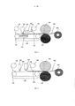
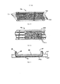
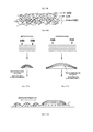
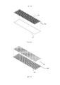
[0034] ФИГ. 1 является схематическим изображением одного из воплощений способа получения абсорбционного композиционного материала с использованием прокатных валков;FIG. 1 is a schematic illustration of one embodiment of a method for producing an absorption composite material using rolling rolls;
[0035] ФИГ. 2 является схематическим изображением другого воплощения способа получения инновационного абсорбционного композиционного материала с использованием прокатных валков;FIG. 2 is a schematic illustration of another embodiment of a method for producing an innovative absorption composite material using rolls;
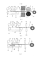
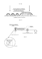
[0036] ФИГ. 3 является схематическим изображением способа по ФИГ. 1 с источником дополнительной энергии;FIG. 3 is a schematic illustration of the method of FIG. 1 with a source of additional energy;
[0037] ФИГ. 4 является вариацией способа, представленного на ФИГ. 1, который использует соединение методом ультразвуковой сварки вместо прокатных валков;FIG. 4 is a variation of the method shown in FIG. 1, which uses an ultrasonic weld joint instead of rolls;
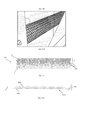
[0038] ФИГ. 5 является вариацией способа, представленного на ФИГ. 2, который использует соединение методом ультразвуковой сварки вместо прокатных валков;FIG. 5 is a variation of the method shown in FIG. 2, which uses ultrasonic welding instead of rolling rolls;
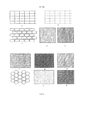
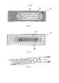
[0039] ФИГ. 6 является иллюстрацией различных потенциальных орнаментов склеивания, которые могут использоваться в заявленных способе и абсорбирующем изделии;FIG. 6 is an illustration of various potential bonding patterns that may be used in the claimed method and absorbent article;
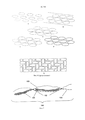
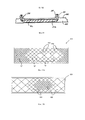
[0040] ФИГ. 7 представляет поперечное сечение карманов, сформированных заявленным способом и используемых в абсорбирующем изделии;FIG. 7 is a cross-sectional view of pockets formed by the claimed method and used in an absorbent article;
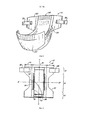
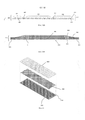
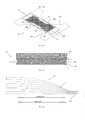
[0041] ФИГ. 8 является видом в перспективе одноразового абсорбирующего изделия с включением абсорбционного композиционного материала;FIG. 8 is a perspective view of a disposable absorbent article incorporating an absorption composite material;
[0042] ФИГ. 9 является видом сверху одноразового абсорбирующего изделия по ФИГ. 8 в плоском и расширенном виде;FIG. 9 is a plan view of the disposable absorbent article of FIG. 8 in a flat and expanded form;
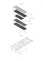
[0043] ФИГ. 10 является изображением в разобранном виде одноразового абсорбирующего изделия по ФИГ. 8;FIG. 10 is an exploded view of the disposable absorbent article of FIG. 8;
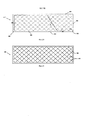
[0044] ФИГ. 11 является парциальным сечением абсорбирующей сердцевинной прослойки, использующей абсорбционный композиционный материал и включенной в одноразовое абсорбирующее изделие;FIG. 11 is a partial cross-section of an absorbent core layer using an absorbent composite material and incorporated into a disposable absorbent article;
[0045] ФИГ. 12 является парциальным сечением абсорбирующей сердцевинной прослойки, использующей альтернативное воплощение инновационного абсорбционного композиционного материала и включенной в альтернативное одноразовое абсорбирующее изделие;FIG. 12 is a partial cross-sectional view of an absorbent core layer using an alternative embodiment of an innovative absorption composite material and included in an alternative disposable absorbent article;
[0046] ФИГ. 13 является видом в поперечном разрезе абсорбирующего изделия с абсорбционным композиционным материалом в манжетах;FIG. 13 is a cross-sectional view of an absorbent article with absorbent composite material in cuffs;
[0047] ФИГ. 14 является видом в поперечном разрезе абсорбирующего изделия с набухшим абсорбционным композиционным материалом в манжетах;FIG. 14 is a cross-sectional view of an absorbent article with swollen absorbent composite material in cuffs;
[0048] ФИГ. 15А-15Г являются упрощенными иллюстрациями абсорбционного композиционного материала согласно заявленному изобретению, с особым акцентом на расположение скоплений поглощающих частиц в композиционном материале;FIG. 15A-15G are simplified illustrations of an absorption composite material according to the claimed invention, with particular emphasis on the location of clusters of absorbent particles in the composite material;
[0049] ФИГ. 16А является упрощенной иллюстрацией предшествующего сэндвича САП;FIG. 16A is a simplified illustration of a prior SAP sandwich;
[0050] ФИГ. 16Б является упрощенной иллюстрацией структуры САП (сэндвич) в соответствии с заявленным изобретением;FIG. 16B is a simplified illustration of the structure of an SAP (sandwich) in accordance with the claimed invention;
[0051] ФИГ. 17А-17Г являются упрощенными иллюстрациями в поперечном разрезе карманов и жидкостных свойств, характеризующих расположение карманов, в соответствии с раскрытием;FIG. 17A-17G are simplified cross-sectional illustrations of pockets and fluid properties characterizing the location of pockets, in accordance with the disclosure;
[0052] ФИГ. 18А является упрощенной схемой способа изготовления абсорбционного композиционного материала согласно раскрытию;FIG. 18A is a simplified diagram of a method for manufacturing an absorption composite material according to the disclosure;
[0053] ФИГ. 18Б-18В являются иллюстрациями или фотографиями образцовых компонентов способа, представленного на ФИГ. 18А;FIG. 18B-18B are illustrations or photographs of exemplary components of the method shown in FIG. 18A;
[0054] ФИГ. 19 является упрощенным видом в разрезе, представляющим абсорбционный композиционный материал в соответствии со способом на ФИГ. 18А;FIG. 19 is a simplified sectional view showing an absorbent composite material in accordance with the method of FIG. 18A;
[0055] ФИГ. 20А являются упрощенным видом в разрезе через боковую среднюю линию одноразового абсорбирующего изделия, использующей поглощающий основной ламинат в соответствии с предпочтительным воплощением раскрытия;FIG. 20A is a simplified sectional view through a lateral midline of a disposable absorbent article using an absorbent core laminate in accordance with a preferred embodiment of the disclosure;
[0056] ФИГ. 20Б представляет упрощенный вид в поперечном разрезе через продольную среднюю линию одноразового абсорбирующего изделия, включающего абсорбирующую сердцевинную слоистую прослойку в соответствии с предпочтительным воплощением раскрытия;FIG. 20B is a simplified cross-sectional view through a longitudinal midline of a disposable absorbent article including an absorbent core laminate in accordance with a preferred embodiment of the disclosure;
[0057] ФИГ. 20В является упрощенным видом в разрезе абсорбционного композиционного материала в абсорбирующей сердцевинной слоистой прослойке по ФИГ. 20А и 20Б;FIG. 20B is a simplified sectional view of an absorbent composite material in an absorbent core laminate according to FIG. 20A and 20B;
[0058] ФИГ. 21 является изображением в разобранном виде абсорбирующей сердцевинной слоистой прослойки согласно воплощению раскрытия;FIG. 21 is an exploded view of an absorbent core laminate according to an embodiment of the disclosure;
[0059] ФИГ. 22А-22В являются изображением в разобранном виде различных стадий производства слоистого материала по ФИГ. 21;FIG. 22A-22B are an exploded view of the various stages of the production of the laminate according to FIG. 21;
[0060] ФИГ. 23 является видом в перспективе сверху рельефной абсорбирующей сердцевинной слоистой прослойки согласно воплощению раскрытия;FIG. 23 is a top perspective view of a relief absorbent core laminate according to an embodiment of the disclosure;
[0061] ФИГ. 24 является видом сверху варианта выполнения абсорбирующей сердцевинной слоистой прослойки, использующей точки склеивания, согласно воплощению раскрытия;FIG. 24 is a plan view of an embodiment of an absorbent core laminate using bonding points according to an embodiment of the disclosure;
[0062] ФИГ. 25 является видом сверху абсорбирующей сердцевинной слоистой прослойки согласно альтернативному воплощению раскрытия;FIG. 25 is a plan view of an absorbent core laminate according to an alternative embodiment of the disclosure;
[0063] ФИГ. 26 является изображением в разобранном виде абсорбирующей сердцевинной слоистой прослойки согласно альтернативному воплощению раскрытия;FIG. 26 is an exploded view of an absorbent core laminate according to an alternative embodiment of the disclosure;
[0064] ФИГ. 27 является упрощенной иллюстрацией этапа изготовления абсорбирующей сердцевинной слоистой прослойки согласно воплощению раскрытия;FIG. 27 is a simplified illustration of a manufacturing step of an absorbent core laminate according to an embodiment of the disclosure;
[0065] ФИГ. 28 является видом сверху одноразового абсорбирующего изделия, включающего абсорбирующую сердцевинную слоистую прослойку, согласно предпочтительному воплощению раскрытия;FIG. 28 is a plan view of a disposable absorbent article comprising an absorbent core laminate according to a preferred embodiment of the disclosure;
[0066] ФИГ. 29 является упрощенной иллюстрацией в поперечном разрезе абсорбционного композиционного материала согласно предпочтительному воплощению раскрытия; иFIG. 29 is a simplified cross-sectional illustration of an absorption composite material according to a preferred embodiment of the disclosure; and
[0067] ФИГ. 30 является упрощенной иллюстрацией парциального сечения точки объемного нетканого материала, склеенной в абсорбционном композиционном материале согласно раскрытию.FIG. 30 is a simplified illustration of a partial cross-section of a point of a bulk nonwoven fabric bonded in an absorption composite according to the disclosure.
ПОДРОБНОЕ ОПИСАНИЕDETAILED DESCRIPTION
[0068] После анализа приведенных подробного описания и сопроводительных чертежей, для обычного специалиста в данной области техники будет очевидно, что абсорбционный композиционный материал, полученный согласно существующему раскрытию, может использоваться в одноразовых абсорбирующих изделиях, и более подробно, в таких одноразовых абсорбирующих изделиях, как детские подгузники, трусики, приучающие к горшку, изделия для взрослых с различными формами недержания. Соответственно, существующее раскрытие не должно быть ограничено структурами и процессами, в частности описанными и проиллюстрированными в данном раскрытии, несмотря на то, что нижеследующее описание в частности, прежде всего, относится к абсорбционному материалу, использующемуся в одноразовом подгузнике. Термин «абсорбирующее изделие» или «абсорбирующий предмет одежды», с которым связано существующее раскрытие, включает различные типы одноразовых изделий и предметов одежды, носимых на или вблизи тела пользователя, чтобы поглотить и удержать различные физические выпоты, выделения организма или биологическую жидкость.[0068] After analyzing the detailed description and accompanying drawings, it will be apparent to one of ordinary skill in the art that the absorption composite material prepared according to the present disclosure can be used in disposable absorbent articles, and in more detail, in disposable absorbent articles such as baby diapers, potty panties, adult products with various forms of incontinence. Accordingly, the present disclosure should not be limited to the structures and processes, in particular described and illustrated in this disclosure, despite the fact that the following description in particular relates primarily to the absorption material used in a disposable diaper. The term “absorbent article” or “absorbent article of clothing”, to which the existing disclosure is associated, includes various types of disposable articles and articles of clothing worn on or near the body of the user to absorb and retain various physical effusions, excretions of the body or biological fluid.
[0069] Возможно, для получения лучшего понимания и оценки определенных предложений и улучшений, представленных в существующем раскрытии, могут предоставить вначале ссылку на улучшения, ранее раскрытые в Патенте США No. 8,148,598. Эти более ранние улучшения описаны по ФИГ. 1-14. Часть предложений там, в дополнение к подтверждению предшествующего уровня техники, может перевести к определенным воплощениям существующего раскрытия (которое станет очевидным для специалиста в данной области техники, относительно заявленного изобретения).[0069] It is possible, in order to gain a better understanding and appreciation of certain proposals and improvements presented in the existing disclosure, they may first provide a link to the improvements previously disclosed in US Patent No. 8,148,598. These earlier improvements are described in FIG. 1-14. Part of the proposals there, in addition to confirming the prior art, may translate to certain embodiments of the existing disclosure (which will become apparent to a person skilled in the art regarding the claimed invention).
[0070] На ФИГ. 1, показана ткань 125, после раскрутки из рулона 120 и подачи вдоль конвейерной ленты 100. Ткань 125 может быть термопластичным материалом, который может быть тканным, нетканым, пленочным, или их сочетанием. Ткань 125 закреплена на конвейерной ленте 100 вакуумной системой 110. Вакуумная система 110 предназначена для закрепления ткани 125 на конвейерной ленте 100.[0070] FIG. 1,
[0071] В одном воплощении поверхность конвейерной ленты 100 имеет углубленные участки, формирующие чашечки в ткани 125, при вытягивании ткани относительно поверхности конвейерной ленты 100. Поверхность конвейерной ленты 100 не ограничивается наличием конструкции, которая формирует чашечки в ткани, но, вместо этого, может формироваться со многими различными поверхностными формами и размерами. Примеры включают выступы-гребни, приподнятые формы и отверстия. Кроме того, поверхностные формы могут быть распределены однородно или неоднородно вдоль ширины и длины конвейерной ленты. Также конвейерная лента 100 может быть плоской. В воплощениях, в которых конвейерная лента 100 имеет отверстия или другую подобную конструкцию, глубина карманов, сформированных в ткани 125, может быть изменена мощностью вакуумной системы 110, эластичностью ткани 125, или сочетанием данных параметров. Кроме того, может использоваться тепло для увеличения эластичности ткани 125, поскольку ткань вытянулась вдоль поверхности конвейерной ленты 100. Тепло может быть приложено к ткани посредством горячей конвейерной ленты или любых других приспособлений, известных в технике. Вакуум 110 может быть применен однородно через поверхность конвейерной ленты 100 или в выбранных расположениях. Например, в конфигурации, в которой поверхность конвейерной ленты 100 имеет углубления, вакуум может быть применен только в углублениях.[0071] In one embodiment, the surface of the
[0072] Частицы САП 135 затем депонированы на ткани 125 при помощи распределителя САП 130. Распределитель САП 130 может принимать конфигурацию для расположения частиц САП в их желаемой позиции в первом слое ткани или может устанавливаться просто для внесения частиц САП на первый слой ткани, в случаях, когда позиционирование частиц САП выполняют другим устройством. Специалисту в данной области техники понятно, что могут быть использованы многочисленные распределители САП 130. Частицы САП 135 могут быть депонированы, расположены, или сочетанием данных методов на ткани 125, при помощи продувания или другими известными методами. Также конвейерную ленту, показанную на ФИГ. 1 могут расположить так, чтобы происходило всасывание сверху вакуумной системой 110. В такой конфигурации ткань 125 пропускают над скоплением частиц САП 135, а частицы САП вводятся на поверхность ткани 125 вакуумной системой 110. В альтернативных воплощениях распределитель САП 130 может включать частицы ухода за кожей, такие как ионообменные смолы, дезодорант, антибактериальные агенты, связующие частицы или другие частицы с полезными свойствами. Далее, несмотря на то, что предпочтительное воплощение направлено на частицы САП, раскрытые методы могут использоваться с любым сочетанием вышеупомянутых частиц, включая сочетания, не включающие САП. Также, отдельные распределители, преимущественным образом расположенные вдоль конвейерной ленты (не показаны), могут использоваться для внесения различных типов частиц, как, например, частиц ухода за кожей.[0072] The
[0073] Частицы САП 135 расположены и сконцентрированы на ткани 125 согласно многим альтернативным методам. В одном воплощении, вакуумная система 110 и ткань 125 может формироваться, чтобы позволить вакуумной системе 110 вытягивать частицы САП 135 относительно поверхности ткани 125 однородно или в определенных областях. В другом воплощении, форма ткани 125 направляет частицы САП 135 в позицию. Например, когда ткань 125 формируется для формирования карманов, частицы САП 135 перекатывватся в карманы в результате воздействия вакуумной системы 110, вибрации конвейерной ленты, ветра, угла конвейерной ленты или сочетаний данных параметров. Также, распределитель(и) САП 130 можно расположить и управлять для предустановленного распределения частиц САП 135 по поверхности ткани 125, при этом данное «стратегическое» расположение включает, но не ограничивается, движением по или против хода конвейерной ленты, будь-то предустановленное или рандомизированное движение. Далее, САП могут располагать таким образом, чтобы получить зоны без частиц САП. Также, частицы САП могут быть расположены с помощью адгезива таким образом, чтобы применяя адгезив к определенным расположениям на поверхности, депонировать частицы САП на поверхности. Помимо этого, частицы САП могут быть расположены на обоих слоях ткани 125 и 155.[0073]
[0074] Как только частицы САП были депонированы и расположены на ткани 125, второй слой ткани 155 вводится в поточную линию из рулона 150. Второй слой ткани 155 может быть выбран из множества материалов, спан-склеенный (фильерный) термопластик или подобный тканый или нетканый материал, пленка или их сочетания.[0074] Once the SAP particles have been deposited and located on
[0075] Адгезив 145 наносят на частицы САП 135 многими способами. ФИГ. 1 показывает, что адгезив 145 нанесли на ткань 155. Альтернативно, адгезив 145 могут применять на ткань 125 и частицы САП 135, на ткань 125 до депонирования частиц САП 135 на ткани 125, или непосредственно к частицам САП, прежде чем они будут депонированы на ткани 125. В еще одном воплощении, адгезив 145 применяют в месте, где ткани 125 и 155 соединены вместе. В еще одном воплощении нанесены множественные слои адгезива. Например, адгезив 145 могут применять на ткань 125, прежде чем частицы САП 135 будут депонированы на ней, к частицам САП 135 после того, как они были расположены на ткани 155, или сочетание этих вариантов. Альтернативно или в дополнение к вышеупомянутым воплощениям, связующие частицы могут смешивать с частицами САП 135. Кроме того, адгезив может быть применен однородно, случайным образом, или в определенном рисунке, в зависимости от желаемых поглощающих свойств готового соединения.[0075]
[0076] Адгезив применяют согласно многим методам, известным специалистам в данной области техники. Например, адгезив можно распылить, раскатать или спаннаносить на поверхность ткани 155. Адгезив может быть гидрофобным, гидрофильным, биоразлагаемым, биополученным, или сочетанием данных вариантов. Предпочтительный адгезив является гидрофобным. Концентрация адгезива в слое варьируется от 1 до 100 г за квадратный метр («г/м2»). Оптимальная концентрация составляет от 5 до 75 г/м2. В предпочтительном воплощении, концентрация составляет от 12 до 50 г/м2. Кроме того, достаточное количество адгезива должно быть использовано для покрытия по крайней мере 25% предназначенной для этого области.[0076] The adhesive is used according to many methods known to those skilled in the art. For example, the adhesive may be sprayed, rolled out, or spun onto the surface of the
[0077] Ткани 125 и 155 затем соединены вместе. ФИГ. 1 показывает систему термического склеивания, в которой используют прокатные валки 160 и 170. Однако, могут использоваться другие системы/методы связывания. Например, может использоваться система ультразвуковой сварки по ФИГ. 4 и 5. Адгезив 145 закрепляет частицы САП 135 в относительно определенном месте относительно тканей во время термокомпрессии и после термокомпрессии. Орнамент склеивания может быть выровнен к распределению частиц САП 135. Также орнамент склеивания могут не выравнивать относительно распределения частиц САП 135. В таких воплощениях, оборудование склеивания может быть адаптировано, чтобы подтолкнуть частицы САП 135 в сторону до склеивания или сцепления через частицы САП 135. Эти воплощения избавляют от необходимости синхронизировать точки склеивания с распределением частиц САП.[0077]
[0078] Ткани 155 и 125 показаны как два материала. Однако специалисту в данной области техники понятно, что ткани могут фактически быть частью того же материала. В такой конфигурации однородная ткань свернута для покрытия частиц САП. Также, края ткани 125 могут быть подогнуты (свернуты) до применения второй ткани 155. В воплощениях, в которых ткани 125 и 155 являются отдельными, ткани 125 и 155 могут быть одним и тем же или различным материалом. Кроме того, ткань 155 может быть доведена до требуемого размера для покрытия определенных областей, таких как центральная область ткани 125.[0078]
[0079] Как только ткани были соединены вместе, абсорбционный композиционный материал 195 собирают на перематывателе 200.[0079] Once the tissues have been joined together, the
[0080] В методе, проиллюстрированном на ФИГ. 2, ткань 125 транспортируется вдоль конвейерной ленты 100. Когда ткань 125 транспортируется вдоль конвейерной ленты 100, тонкий слой адгезива 145 наносят на ткань 125. Как с методом по ФИГ. 1, адгезив может быть применен однородно, случайным образом, или с определенным орнаментом, в зависимости от желаемых поглощающих свойств готового композиционного материала. Несмотря на то, что показан адгезив 145 с применением до нанесения частиц САП 135, предполагаются также и альтернативные воплощения. Например, адгезив может быть применен согласно воплощениям, описанным по ФИГ. 1.[0080] In the method illustrated in FIG. 2,
[0081] После применения адгезива частицы САП 135 депонированы и расположены на ткани 125. Частицы САП 135 могут быть депонированы непосредственно на ткани 125, как показано на ФИГ. 2, или косвенно, например, при помощи продувания, перемещающего частицы САП через ткань 125. Вес частиц САП дополнительно способствует закреплению ткани 125 к конвейерной ленте 100. Кроме того, частицы САП могут быть расположены согласно способу, подобному раскрытому по ФИГ. 1.[0081] After application of the adhesive,
[0082] Второй слой ткани 155 затем подают в поточную линию из рулона 150. Второй слой ткани располагают для покрытия частиц САП 135. Адгезив 145 препятствуют тому, чтобы частицы САП перемещались свободно между этими двумя тканями. Получаемая прослоенная структура затем транспортируется в прокатные валки для термосклеивания. Как описано по ФИГ. 1, орнамент склеивания могут не выравнивать относительно частиц САП 135. Абсорбционный композиционный материал 195 собирают на перематывателе 200. Как описано по ФИГ. 1, ткани 125 и 155 могут быть частью одинарного листа. Кроме того, ткани могут быть свернуты образом, описанным по ФИГ. 1. В другом воплощении ткань 125 может быть покрыта адгезивом и запрессована над скоплением частиц САП.[0082] A second layer of
[0083] ФИГ. 3 аналогична ФИГ. 1 и 2, за исключением того, что источник энергии 900, например, печь или микроволновый генератор располагают вдоль сборочного конвейера. Источник энергии излучает тепло и/или излучение 910, которые могут использоваться для расплавления термосвязующего пластика. Количество тепла может также быть отрегулировано для расплавления определенных типов частиц или волокон, определенных участков (областей) тканей, или только внешних слоев частиц/связующего.FIG. 3 is similar to FIG. 1 and 2, except that an
[0084] ФИГ. 4 и 5 аналогичны ФИГ. 1 и 2, за исключением того, что ткани соединены вместе с помощью ультразвукового скрепления (сварки). ФИГ. 4 и 5 показывают систему ультразвукового скрепления (210а и 210б). Понятно, что ФИГ. 1-5 показывают различные воплощения нового метода и что аспекты различных методов могут быть полезным образом объединены в зависимости от требований. Важным для всех сочетаний, однако, является объем адгезива 145, частиц связующего, или применения сочетаний данных параметров к частицам САП 135 и силе скрепления. Как следует заметить относительно ФИГ. 1, оптимальная концентрация адгезива составляет от 12 до 50 г/м2, хотя приемлемы и другие концентрации. Во всех воплощениях важно, чтобы концентрация адгезива 145 была достаточно высокой для предотвращения перемещения частиц САП 135. Концентрация не должна быть слишком высокой, однако достаточной для того, чтобы покрывать частицы САП 135 и уменьшить набухание САП. Адгезив должен только предотвращать миграцию достаточного количества частиц САП 135 для обеспечения универсальной абсорбции. Несмотря на то, что не представлено, специалисту в данной области техники понятно, что то источник энергии 900, показанный на ФИГ. 3, могут также быть применять в конфигурациях, показанных на ФИГ. 2, 4 и 5.FIG. 4 and 5 are similar to FIG. 1 and 2, except that the tissues are joined together by ultrasonic bonding (welding). FIG. 4 and 5 show an ultrasonic bonding system (210a and 210b). It is clear that FIG. 1-5 show various embodiments of the new method and that aspects of the various methods may be usefully combined depending on requirements. Important for all combinations, however, is the amount of adhesive 145, binder particles, or the application of combinations of these parameters to
[0085] ФИГ. 6(A)-(q) показывают различные орнаменты склеивания, рассмотренные методом. Орнаменты склеивания могут полностью замыкать область, частично замыкать область или обеспечить локальные зоны склеивания. Линии и пункты указывают склеенные участки. Сплошные линии изображают поверхности склеивания. Поверхности склеивания могут сформировать открытые формы или замкнутые формы, те, которые могут быть найдены в примерах (а) и (в), изображающие непрерывные поверхности склеивания, полностью замыкают карманы частиц САП 135 или, как в примере (ж), разграничивающие различные области абсорбционного композиционного материала. Пунктирные линии, те, которые могут быть найдены в примерах (б) и (m), являются прерывистыми орнаментами склеивания, не полностью замыкающими карманы частиц САП 135. В этих конфигурациях миграция сухих частиц САП предотвращается адгезивными и непрерывными или орнаментами склеивания. Прерывистыми орнаментами склеивания можно заменить непрерывные орнаменты склеивания и наоборот. Далее, хотя ФИГ. 6 показывает или непрерывные или прерывистые орнаменты склеивания, могут использоваться сочетания прерывистых и непрерывных орнаментов склеивания.FIG. 6 (A) - (q) show the various bonding ornaments examined by the method. Gluing ornaments can completely lock an area, partially lock an area, or provide local bonding zones. Lines and points indicate glued areas. Solid lines depict bonding surfaces. Gluing surfaces can form open forms or closed forms, those that can be found in examples (a) and (c), depicting continuous gluing surfaces, completely close the pockets of
[0086] ФИГ. 7 показывает парциальное сечение абсорбционного композиционного материала 195. ФИГ. 7 показывает, как склеивания 192 могут действовать для разделения карманов частиц САП 135. Обращая внимание на орнамент склеивания, частицы САП 135 могут быть полностью замкнуты в карманах, определенных рисунком связывания, частично приложенным в карманах, определенных орнамент склеивания или просто ограниченных орнамент склеивания. Ограничение в этом контексте означает, что частицы САП 135 не могут мигрировать непосредственно из одной области сердцевины в другую область, но вместо этого, должны перемещаться около склеенных участков.FIG. 7 shows a partial cross section of the
[0087] Особенно, многочисленные функции или полезные свойства получены в абсорбционном композиционном материале путем варьирования суммы частиц САП, типа и числа используемых слоев тканей, и структурных переменных, например, соотношение САП к адгезиву, и применения абсорбционного композиционного материала в различных расположениях в изделии. Такие технологии производства и методы расчета могут быть включены в структурные проектирования и методы существующего раскрытия.[0087] Especially, numerous functions or useful properties are obtained in the absorbent composite material by varying the sum of SAP particles, the type and number of tissue layers used, and structural variables, for example, the ratio of SAP to adhesive, and applying the absorption composite material at various locations in the product. Such production technologies and calculation methods can be incorporated into structural design and existing disclosure methods.
[0088] Кроме того, специалисту в данной области техники понятно, что процесс для изготовления одной порции абсорбционного композиционного материала, описанного выше, может быть изменен для производства множества партий слоистого абсорбционного композиционного материала. В структурах, включающих многочисленные слои, слои могут быть листами абсорбционного композиционного материала 195, которые являются совместно ламинированными (расслоенными) для формирования единой структуры или перемежающихся слоев ткани и частиц САП 135, которые формируют единую структуру. Специалисту в данной области техники понятно, что перемежающиеся слои могут быть получены путем нанесения адгезива поверх ткани 155 (ФИГ. 1), применения второго слоя частиц САП 135, и третьего слоя ткани (не показано). Точно так же могут быть добавлены дополнительные слои, ограничены только максимальной толщиной, подходящей для термокомпрессии.[0088] Furthermore, one of ordinary skill in the art will understand that the process for manufacturing one portion of the absorption composite material described above can be modified to produce multiple batches of layered absorption composite material. In structures including multiple layers, the layers may be sheets of
[0089] Частицы САП 135 могут быть покрыты смешивающимся, гидрофобным материалом. Покрытие действует как барьер или мембрана, первоначально замедляющие поглощение жидкости, таким образом экономя вместительность САП для дополнительных или вторичных поступлений. В данном случае, покрытие выравнивает показатели абсорбции между поступлениями. В процессах, показанных на ФИГ. 1-5, покрытие может быть применено до нанесения адгезива 145, после того, как наносят адгезив 145, или одновременно. Также адгезив может быть смешан с материалом покрытия.[0089] The
[0090] В одном примере, тонкий слой минерального масла нанесли на частицы САП 135. Покрытие задерживает начальное поглощение жидкости частицами САП и позволяет жидкости распределиться в изделии в течение большего количества времени. Предпочтительно, минеральное масло применяют в концентрации приблизительно от 0,00001 граммов на грамм САП до приблизительно 0,1 грамм на грамм САП (в зависимости от определенного дизайна продукта). Также минеральное масло могут применять в определенных целевых зонах. Таким образом, полученная жидкость преимущественно первоначально распределяется в области, свободные от покрытия, прежде чем будут активированы и начнут разбухать области с покрытием.[0090] In one example, a thin layer of mineral oil was applied to the
[0091] Абсорбционный композиционный материал, полученный вышеописанным процессом, может использоваться для одноразового абсорбирующего изделия или как один или более компонентов одноразового абсорбирующего изделия. Компоненты поглощающей статьи включают изнаночный и лицевой листы, абсорбирующую сердцевинную прослойку, герметизирующие стенки или манжеты (включая буфы штанин), изнаночный лист/абсорбционный сердцевинный композиционный материал, лицевой лист/абсорбционный композиционный материал и сочетания вышеупомянутых слоев. Такая структура описано далее более подробно.[0091] The absorbent composite material obtained by the above process can be used for a disposable absorbent article or as one or more components of a disposable absorbent article. The components of the absorbent article include the back and front sheets, the absorbent core, the sealing walls or cuffs (including pant puffs), the back / absorption core composite material, the front sheet / absorption composite material, and combinations of the above layers. Such a structure is described below in more detail.
[0092] ФИГ. 8 является видом в перспективе одноразового абсорбирующего изделия с включением абсорбционного композиционного материала в форме подгузника 10. Подгузник 10 включает лицевой лист 50, изнаночный лист 60 и абсорбирующую сердцевинную прослойку (не показана). Подгузник далее включает приподнятые барьерные манжетки 34, которые расположены в продольном направлении вдоль подгузника и прорезинены для комфортного прилегания к ягодицам пользователя. Кроме того, подгузник включает резинку 52 и элементы застежки 26. Элемент 26, при ношении, вытягивается и закрепляется на соответствующем противоположном конце подгузника для закрепления подгузника на пользователе.FIG. 8 is a perspective view of a disposable absorbent article incorporating an absorbent composite material in the form of a
[0093] ФИГ. 9 иллюстрирует сложную сетчатую структуру подгузника 10 по ФИГ. 8 в обычной плоской и развернутой конфигурации. Как будет объяснено далее по тексту, сетчатая структура может быть впоследствии обрезана, сложена, запечатана, обработана сваркой и/или иным образом для формирования одноразового подгузника 10 в готовой форме. Для упрощения описания подгузника 10, описание отсылает к пролегающей в продольном направлении оси AA, латерально пролегающей центральной оси BB, паре продольно пролегающих боковых краев 90 и паре концевых краев 92, которые расположены между боковыми краями 90. Вдоль продольной оси AA подгузник 10 включает первую концевую область или область талии спереди 12, вторую концевую область или область талии сзади 14, и область промежности 16, расположенную между ними. Каждая из областей талии передней и задней части 12, 14 характеризуется парой областей ушек 18, которые расположены по обе стороны от центра стана, делят на части 20 и простираются со стороны от боковых краев 90. Структура застежки 26 (например, стандартная застежка ленты) присоединяется к каждому из ушек 18 вдоль задней области талии 14 из подгузника 10.FIG. 9 illustrates the complex mesh structure of the
[0094] Когда подгузник 10 носят на талии, к области талии спереди 12 прилегает смежная передняя область талии пользователя, к области талии сзади 14 прилегает смежная задняя область талии, а область промежности 16 прилегает вокруг и под областью промежности. Для надлежащего прилегания подгузника 10 к пользователю, ушки 18 из области талии сзади 14 обхватывают талию владельца в передней части и выравниваются с ушками 18 из области талии спереди 12. Поверхность прилегания может быть расположена на или обеспечена внутренней или внешней поверхностью области талии спереди 12. Также застежки 26 могут быть расположены на ушках 18 из области талии спереди 12 и выполнены с возможностью прикрепления к ушкам 18 из области талии сзади 14.[0094] When the
[0095] ФИГ. 10 является изображением в разобранном виде подгузника по ФИГ. 8 и 9. Подходящая структура подгузника, как правило, использует, по крайней мере, три уровня. Эти три уровня включают изнаночный лист 60, абсорбирующую сердцевину 46 и лицевой лист 50. Основная часть структуры подгузника может не содержать пару герметизирующих стенок или буф штанин (барьерные манжетки) 34, расположенных вверх от лицевого листа 50 и предпочтительно снабженных, по крайней мере, одним или несколько расположенными независимо, в длину эластичными компонентами 38. Как будет показано далее, любой из этих элементов подгузника или сочетание этих элементов могут быть изготовлены из или использовать абсорбционный композиционный материал 195. Кроме того, впитывающий слой 48 может быть добавлен для улучшения характеристик изделия.FIG. 10 is an exploded view of the diaper of FIG. 8 and 9. A suitable diaper structure typically uses at least three levels. These three levels include a
[0096] ИЗНАНОЧНЫЙ СЛОЙ[0096] WRITTEN LAYER
[0097] Как упомянуто выше, подгузник 10 использует изнаночный лист 60, покрывающий сердцевину 46 и предпочтительно простирающийся вне сердцевины 46 к боковым краям 90 и концевым краям 92 из подгузника 10. В одном аспекте изобретения, изнаночный лист 60 изготовлен из однослойного листа абсорбционного композиционного материала 195. В такой конфигурации, ткань 125 расположена как наружная поверхность изнаночного листа 60.[0097] As mentioned above, the
[0098] Кроме того, альтернативная структура могла использоваться для гелевого блокирования. Для применения с помощью гелевого блокирования, изнаночный лист инновационного одноразового абсорбирующего изделия одноразового абсорбирующего изделия выполняют относительно тонким и обеспечивающим улучшенную гибкость. В сухом состоянии, изнаночный лист остается мягким и дышащим, но, после смачивания, формируется тонкий слой блокирующего геля (т.е. на внутренней поверхности изнаночного листа), который отдает изнаночный лист, существенно жидкий непроницаемый. Блокирующий гель формируется набуханием частиц САП 135.[0098] In addition, an alternative structure could be used for gel blocking. For gel blocking applications, the back sheet of an innovative disposable absorbent article of a disposable absorbent article is relatively thin and provides improved flexibility. In the dry state, the underside of the sheet remains soft and breathable, but after wetting, a thin layer of blocking gel forms (i.e., on the inside of the underside of the sheet), which renders the underside of the sheet substantially liquid impermeable. A blocking gel is formed by swelling of
[0099] ЛИЦЕВОЙ СЛОЙ[0099] FACIAL LAYER
[00100] Точно так же, абсорбционный композиционный материал 195 могут использовать вместе с или как лицевой лист одноразового абсорбирующего предмета одежды. Лицевой лист 50 является предпочтительно мягким, приспосабливаемым, упругим и с низкой повторной смачиваемостью от жидкого водопроницаемого материала. Лицевой лист 50 помещается в непосредственную близость от кожи владельца, когда подгузник 10 носят. Таким образом, такой лицевой лист 50 позволяет поступающей жидкости быстро проникать через него, чтобы течь к сердцевине 46 более быстро, но препятствуя поступающей жидкости вытекать из задней части через лицевой лист 50. Лицевой лист 50 может быть изготовлен из любого материала из широкого ряда водо- и паропроницаемых гидрофильных материалов. Поверхность (поверхности) лицевого листа может быть обработана с сурфактантом, чтобы упростить передачу жидкости через нее, особенно в центральной зоне или области лицевого листа, расположенного по сердцевине и внутренней поверхности сердцевины. Лицевой лист может также быть покрыт веществом, обладающим свойством предотвращать или уменьшать сыпь (например, алоэ вера).[00100] Similarly, the
[00101] В одном примере, лицевой лист 50 формируется из абсорбционного композиционного материала 195, который покрывает существенно всю поверхность абсорбирующего изделия 10, включая существенно всю область талии спереди 12, область талии сзади 14 и область промежности 16. Далее, уровень ушка внутренней области 18 формируется из того же самого материала лицевого листа и, таким образом, может рассматриваться как единый лицевой лист 50 в формовочных боковых расширениях материала лицевого листа. Также, лицевой лист 50 может быть сформирован из многочисленных различных материалов, отличающихся по ширине лицевого листа 50. Такой дизайн из многочисленных составных частей допускает создание предпочтительных свойств и различные зоны лицевого листа.[00101] In one example, the
[00102] АБСОРБИРУЮЩАЯ СЕРДЦЕВИННАЯ ПРОСЛОЙКА[00102] ABSORBENT CORE LAYER
[00103] В дополнение к или как альтернатива вышеупомянутым примерам, абсорбирующая сердцевинная прослойка одноразового абсорбирующего изделия может быть изготовлена из абсорбционного композиционного материала 195, слоистых уровней абсорбционного композиционного материала 195 (не показаны) или многочисленных слоев частиц САП 135 и ткани. ФИГ. 11 и 12 изображают поперечные представления перемежающихся слоев частиц САП 135 и ткань, которые формируют многослойный абсорбционный композиционный материал 700 и 900, соответственно. Как показано в этих рисунках, сердцевина 46 может состоять из различных слоев частиц САП 135 (710 и 910). Слои могут быть однородными или неоднородными, в зависимости от применения по назначению. В неоднородном многослойном абсорбционном композиционном материале 900, концентрация частиц САП 135 может отличаться в данном слое, между слоями или в различных сочетаниях упомянутых параметров.[00103] In addition to or as an alternative to the above examples, the absorbent core of the disposable absorbent article may be made of
[00104] ФИГ. 11 изображает композиционную структуру 700, в которой слои частиц САП 710 и тканевые слои 720 чередуются для формирования завершенной сложной структуры 700. Многослойный дизайн может также быть получен путем скрепления/склеивания вместе листов абсорбционного композиционного материала, сворачивания единого листа абсорбционного композиционного материала или изготовления абсорбционного композиционного материала с многочисленными слоями во время производственного процесса. В вариантах с подгибкой, сложным сгибом может быть С-сгиб, Z-сгиб, V-сгиб, W-сгиб или их сочетания. Далее, сгибы могут быть открытыми, закрытыми, или перехлестываться друг с другом.FIG. 11 shows a
[00105] ФИГ. 12 изображает многослойный абсорбционный композиционный материал 900. Как показано на ФИГ. 12, области высоких концентраций частиц САП 910 могут быть стратегически расположены для обеспечения дополнительной абсорбции в определенных участках, таких как промежность абсорбирующего изделия. Специалист в данной области техники понимает, что области высокой концентрации могут быть дополнены для управления объемом и направлением проникающей жидкости. Кроме того, слой с зонами высоких концентраций может быть объединен с уровнями существенно однородных слоев. Также высокие области концентрации САП могут быть сформированы путем расположения многочисленных слоев абсорбирующей сердцевины.FIG. 12 depicts a multilayer
[00106] Сердцевину могут конфигурировать для растягивания полной длины и/или ширины одноразового абсорбирующего изделия. Предпочтительно, однако, чтобы сердцевина была расположена или иным образом сконцентрирована в области промежности изделия. В различных воплощениях, сердцевина распространяется на края изделия, и частицы САП 135 сконцентрированы в области промежности или другой целевой зоне изделия. В еще одном воплощении, частицы могут быть сочетанием частиц САП, частиц ухода за кожей, таких, как ионообменные смолы, дезодорант, антибактериальные агенты, связующие частицы или другие частицы с полезными свойствами.[00106] The core may be configured to stretch the full length and / or width of the disposable absorbent article. Preferably, however, the core is located or otherwise concentrated in the crotch region of the article. In various embodiments, the core extends to the edges of the product, and
[00107] ГЕРМЕТИЗИРУЮЩИЕ СТЕНКИ[00107] SEALING WALLS
[00108] По ФИГ. 13 и 14, одноразовое абсорбирующее изделие 10 использует пару герметизирующих стенок или манжеток 34, которые включают абсорбционный композиционный материал 195. Каждая герметизирующая стенка 34 является в длину простирающейся стеночной структурой, предпочтительно расположенной на каждом боковом крае сердцевины 46 и располагаемой со стороны от продольного центра. Продольные торцы стенок 34 могут быть прикреплены, например, к лицевому листу 50 в передней части и задних областях талии 12 и 14. Предпочтительно, торцы герметизирующей стенки 34 прикреплены внизу внутри и склеены, например, адгезивом к сетчатой структуре. Такая структура оказывает эффективное влияние на герметизирующую стенку 34 внутри и, как обычно предполагается, позволяет лучше предотвратить протекание жидкости через герметизирующую стенку 34.[00108] According to FIG. 13 and 14, the disposable
[00109] ФИГ. 13 обеспечивает вид в разрезе подгузника 10. Подгузник 10 включает изнаночный лист 60, абсорбирующую сердцевину 46, впитывающий слой 48 и лицевой лист 50. Как показано на ФИГ. 13, сердцевина выполнена из абсорбционного композиционного материала 195. Подгузник 10 также включает пару герметизирующих стенок или манжеток 34, которые формируются путем сгибания лицевого листа 50 и подворачивания его на концах абсорбционного композиционного материала 195. Также, абсорбционный композиционный материал 195 в манжетах 34 может быть отличным от материала абсорбирующей сердцевины 46.FIG. 13 provides a cross-sectional view of the
[00110] Предпочтительно, герметизирующие стенки 34 снабжены эластичными элементами 38, которые простираются практически вдоль всей длины герметизирующих стенок 34. Во время ношения, эластичные элементы 38 размещаются в герметизирующих стенках 34, предпочтительно наверху герметизирующих стенок 34, в то время как в вытянутом состоянии и будучи приклеенными к герметизирующим стенкам, по крайней мере, по их краям. В расслабленном положении, эластичные элементы 38 распружиниваются вовнутрь. Во время ношения изделия 10, эластичные элементы 38 сжимают герметизирующие стенки 34 на ягодицах и бедрах пользователя таким образом, чтобы получить сжатие между изделием 10, ягодицами и бедрами. Сердцевина 46 могут быть одинарным листом абсорбционного композиционного материала 195 или многослойным, как описано выше.[00110] Preferably, the sealing
[00111] ФИГ. 13 изображает конфигурацию герметизирующих стенок 34, в мягком и сухом состоянии. ФИГ. 14, с другой стороны, изображает герметизирующие стенки после смачивания, в котором абсорбционный композиционный материал 195 раздулся для расположения герметизирующих стенок 34 в упругом вертикальном положении. В отличие от классических буф штанин в предшествующей технике, упругие вертикальные герметизирующие стенки 34 сопротивляются сплющиванию (например, когда пользователь садится), и, таким образом, гарантируют предотвращение протекания, особенно во время неожиданных жидких испражнений и мочевых выделений.FIG. 13 shows the configuration of the sealing
[00112] ДОПОЛНИТЕЛЬНЫЕ СЛОИ[00112] ADDITIONAL LAYERS
[00113] Одноразовое абсорбирующее изделие может использовать дополнительные слои, включая впитывающий слой или поглощающий слой 48, предпочтительно расположенный между лицевым листом и сердцевиной (например, ФИГ. 10). Одной из функций такого слоя является распределение или рассеяние потока жидкости так, чтобы жидкость была распределена более равномерно по поверхности сердцевины. Это служит для замедления потока с тем, чтобы было достаточно времени для поглощения жидкости сердцевиной. Впитывающий слой также предназначен для того, чтобы препятствовать локальному насыщению сердцевины, в то время как большая часть сердцевины не поглощает жидкости.[00113] The disposable absorbent article may use additional layers, including an absorbent layer or an
[00114] ПЕТЕЛЬКИ И ЛЕНТЫ[00114] LOOPS AND BANDS
[00115] Одноразовое абсорбирующее изделие должно быть закреплено на пользователе. Это является самым важным в качестве подгузников, так как подгузники не надеваются так, как спортивные штаны или приучающие трусики, а застегиваются вокруг пользователя. Закрепляющие элементы дополняют эластичные элементы путем квазиуплотнения между пользователем и поясом и буфами штанин, таким образом, чтобы жидкость задерживалась в изделии и затем впитывалась; другими словами, так, чтобы не просачивалась через разрывы между пользователем и краем изделия. Закрепляющие элементы могут быть адгезивными, механическими деталями застежек на липучке, или натягивающимися крючками-застежками, т.е. закрепляющими один край изделия к продольно противоположному краю. Закрепляющие элементы могут также со-адгезивно закрепленными друг с другом, таким образом, что они совместно поддерживаются, но не с другими материалами.[00115] The disposable absorbent article should be secured to the user. This is most important as diapers, as diapers are not worn like sweatpants or accustomed panties, but are fastened around the wearer. The fastening elements complement the elastic elements by quasi-sealing between the wearer and the belt and pant puffs so that the liquid lingers in the product and then is absorbed; in other words, so that it does not seep through the gaps between the user and the edge of the product. The fastening elements can be adhesive, mechanical parts of Velcro fasteners, or stretchable hook-and-loop fasteners, i.e. securing one edge of the product to the longitudinally opposite edge. The fastening elements can also be co-adhesive bonded to each other, so that they are jointly supported, but not with other materials.
[00116] В примерах, показанных в иллюстрациях (см., например, ФИГ. 10), изделие 10 присоединяется к пользователю застежками ленты 26, которые постоянно присоединены к (например, вшиты непосредственно в), изнаночному листу 60. Ленточные застежки 26 завязываются с поперек противоположным ушком 2, выступая из изнаночного листа там, где они остаются присоединенными благодаря адгезивному составу, нанесенному на застежки 26. Также изделие 10 может быть приучающими штанами, подгузниками без застежек, и т.п. В этой конфигурации у изделия 10 может не быть ленточных застежек 26.[00116] In the examples shown in the illustrations (see, for example, FIG. 10), the
[00117] ПОЯСНЫЕ ПОЛОСЫ[00117] BANDBARS
[00118] Поясные полосы с эластичными элементами 52 расположены вдоль поперечной части изделия 10 так, чтобы при ношении поясные полосы были расположены вдоль талии владельца. Обычно пояс предпочтительно создает квазиуплотнение на талии (поперечные эластичные элементы 52) так, чтобы жидкие выделения не просачивались из областей между эластичной талией и талией пользователя. Квазиуплотнение является значительным, потому что, несмотря на то, что жидкость может быть в конечном счете поглощена наполнителем, поступление жидкости может превысить показатель поглощения наполнителя. Следовательно, пояса впитывают жидкость во время ее поглощения. Во-вторых, пояса могут иметь вместительность для поглощения жидкости (см., например, Патент США №5,601,544, который настоящим включен посредством ссылок).[00118] The waist bands with
[00119] Скопления частиц в орнаментах, рельефные орнаменты и выбор материала для поглощающих ворсистых композиционных изделий[00119] The accumulation of particles in the ornaments, embossed ornaments and the choice of material for absorbent fleecy composite products
[00120] Упрощенные иллюстрации ФИГ. 15А-15Г представляют абсорбционные композиционные материалы 510 с особенно преимущественным расположением скоплений 512 поглощающих частиц, согласно существующему раскрытию (с подобными справочными цифрами, используемыми для указания как элементы). Относясь сначала к ФИГ. 15А, каждое из скоплений на абсорбционном композиционном материале 510 представлено ромбовидным вложением 514 в орнаменте. В предпочтительных воплощениях, САП используется как поглощающие частицы в скоплениях. Кроме того, скопления САП в каждой из ФИГ. 15А-15Г, предпочтительно сохраняются на месте и стабилизируются физическими скреплениями или контейнерами, обеспеченными скреплением первого слоя ткани, располагаемого обычно выше скопления САП, со вторым слоем ткани, располагаемым обычно ниже скопления САП. Таким образом, в альтернативном представлении ФИГ. 15А, ромбовидные участки представляют схему контейнеров или карманов, отражающихся в конкретных вариантах, скреплении лицевой ткани с изнаночной тканью, как ранее описано в данном раскрытии.[00120] Simplified illustrations of FIG. 15A-15G represent absorption
[00121] Как описано ранее, на абсорбирующие характеристики САП могут повлиять размер и структура контейнера. Поскольку САП становятся более влажными, их проницаемость уменьшается. Вода не может пройти через частицу САП из-за высокого уровня воды, уже содержащейся в частице САП, и в конечном счете САП может полностью остановить прохождение дальнейшей жидкости через них. Это известно как блокирование геля. Кроме того, поскольку САП становятся более влажным, они разбухают и их объем увеличивается. Путем ограничения САП в маленьком контейнере постоянного объема возможно ограничить набухание САП и препятствовать тому, чтобы они достигли своего самого высокого уровня насыщенности (и, соответственно, предотвращая САП достичь самых низких уровней проницаемости). Степень ограничения параметров частицы САП зависит от ряда факторов, включая: предназначение и размер контейнера, размер и частота любых разрывов в контейнере (например, вдоль боковых стенок), объем САП, расположенных в контейнере и объем жидкости, поглощенной САП. Далее, на свойства САП влияет степень их насыщения. В частности, поглощающие комплексные параметры, такие как проницаемость, показатель поглощения, капиллярное давление (являющееся результатом присутствия вакуума в композиционном соединении) различаются значительно, по мере изменения состояния САП от сухого до полностью влажного. В соответствии с заявленным способом по данному раскрытию, целевое или оптимальное исполнение САП может быть достигнуто путем изменения размера контейнера и/или концентрации САП, чтобы физически ограничить набухание САП и контролировать точку максимального насыщения САП. Путем комбинирования этих физических характеристик, предпочтительные уровни проницаемости или предпочтительная абсорбция могут быть достигнуты в целевых областях абсорбирующей сердцевины. Таким образом, путем подбора двух переменных, размера кармана и количества САП в кармане, может быть «установлена» минимальная проницаемость контейнера или кармана. В карманах некоторых областях подгузника можно предотвратить блокирование геля, и проницаемость соответствующей области сердцевины может быть оптимизирована. Градиент размера кармана может также быть установлен для получения максимального потока и использования абсорбирующей сердцевины. Этот градиент будет проходить от целевой зоны к краям или бокам подгузника.[00121] As described previously, the size and structure of the container may affect the absorbent characteristics of the EPS. As SAPs become wetter, their permeability decreases. Water cannot pass through the SAP particle due to the high level of water already contained in the SAP particle, and ultimately the SAP can completely stop the passage of further fluid through them. This is known as gel blocking. In addition, as SAPs become wetter, they swell and their volume increases. By limiting the SAP in a small container of constant volume, it is possible to limit the swelling of the SAP and prevent them from reaching their highest saturation level (and thus preventing the SAP from reaching the lowest permeability levels). The degree of restriction of the parameters of the SAP particles depends on a number of factors, including: the purpose and size of the container, the size and frequency of any breaks in the container (for example, along the side walls), the volume of SAP located in the container and the volume of liquid absorbed by the SAP. Further, the degree of saturation affects the properties of SAP. In particular, the absorbing complex parameters, such as permeability, absorption index, capillary pressure (resulting from the presence of vacuum in the composite compound) differ significantly as the SAP state changes from dry to completely wet. In accordance with the claimed method according to this disclosure, the target or optimal performance of the SAP can be achieved by changing the container size and / or concentration of the SAP to physically limit the swelling of the SAP and control the point of maximum saturation of the SAP. By combining these physical characteristics, preferred permeability levels or preferred absorption can be achieved in the target areas of the absorbent core. Thus, by selecting two variables, the size of the pocket and the number of SAPs in the pocket, the minimum permeability of the container or pocket can be “set”. In the pockets of some areas of the diaper, gel blocking can be prevented, and the permeability of the corresponding core region can be optimized. A pocket size gradient can also be set to maximize flow and use an absorbent core. This gradient will extend from the target area to the edges or sides of the diaper.
[00122] Различные расположения контейнеров или карманов также способствуют надлежащему использованию САП и препятствуют тому, чтобы жидкость обошла контейнеры. Идеально, жидкость должна просочиться или вытекать из контейнера к контейнеру, поскольку САП достигает максимального уровня насыщенности, установленной или свойствами САП или объемом кармана, в котором они набухают. Заявители придерживаются мнения, что в некоторых ранее описанных композиционных материалах или расположениях карманов (см. ФИГ. 6), прослеживается тенденция протекания жидкости между карманами. Это - жидкие протеки вдоль каналов, сформированных рельефными линиями, и не впитывающиеся в сердцевину. Для уменьшения этой тенденции, предпочтительными являются расположения или орнаменты для контейнеров, минимизирующие или устраняющие короткие и прямые маршруты (например, вдоль рельефных линий) потока жидкости от центра сердцевины до ее боковых краев (на краях концов). Для иллюстрирования, контейнеры или карманы, сформированные в виде ромбов, более предпочтительны, чем сформированные в виде квадратов или прямоугольников, потому что диагональные линии или каналы, сформированные ромбовидными контейнерами, являются более длительными при удержании жидкости и менее прямолинейными. Окружности также являются эффективными, если упакованы без каналов, протекающих быстро к краю. В более предпочтительных воплощениях, поток жидкости вынужден изменить направления один или несколько раз прежде, чем перетечь через край подгузника.[00122] The different locations of the containers or pockets also contribute to the proper use of the EPS and prevent the liquid from bypassing the containers. Ideally, the liquid should leak or leak from the container to the container, since the SAP reaches the maximum level of saturation established either by the properties of the SAP or by the volume of the pocket in which they swell. Applicants are of the opinion that in some of the previously described composite materials or locations of pockets (see FIG. 6), there is a tendency for fluid to flow between the pockets. These are liquid proteins along channels formed by relief lines and not absorbed into the core. To reduce this tendency, arrangements or ornaments for containers are preferred that minimize or eliminate short and direct routes (for example, along the relief lines) of fluid flow from the center of the core to its lateral edges (at the ends of the ends). To illustrate, containers or pockets formed in the form of rhombuses are more preferable than those formed in the form of squares or rectangles, because diagonal lines or channels formed by diamond-shaped containers are longer in fluid retention and less straightforward. Circles are also effective if packed without channels flowing quickly to the edge. In more preferred embodiments, the fluid flow is forced to change directions one or more times before flowing over the edge of the diaper.
[00123] Абсорбирующая сердцевинная прослойка для детского подгузника или изделия для взрослых с различными формами недержания требует быстрого поглощения жидкости, в анатомически выстроенной области сердцевины, поглощать всю жидкость без протекания на боках или концах изделия и удержания этой жидкости без смачивания кожи пользователя, особенно под давлением, вызванным массой тела пользователя. Заявленное раскрытие выполняет эту задачу путем обеспечения наличия областей сердцевины, определяющих различные эксплуатационные параметры при помощи варьирования размера контейнеров, содержащих САП, а также расположения контейнеров. Таким образом, сердцевина может быть создана для достижения оптимизированных рабочих характеристик путем изменения размера кармана и/или концентрации САП в данном кармане.[00123] The absorbent core for a baby diaper or adult product with various forms of incontinence requires rapid absorption of fluid, in the anatomically aligned region of the core, to absorb all the fluid without leakage on the sides or ends of the product and hold this fluid without wetting the user's skin, especially under pressure caused by the user's body weight. The claimed disclosure accomplishes this task by ensuring the presence of core regions defining various operational parameters by varying the size of containers containing EPS, as well as the location of the containers. Thus, the core can be created to achieve optimized performance by changing the size of the pocket and / or the concentration of SAP in this pocket.
[00124] В определенных воплощениях, показанных здесь, особенности дизайна объединены для обеспечения сердцевины, которая с меньшей вероятностью допустит протекание жидкости, быстро поглощает влагу и предоставляет сухое, удобное изделие при ношении пользователю. В области промежности сердцевины, размер контейнера и загрузка САП оптимизированы для обеспечения открытой структуры, с высокой проницаемостью, приводящей к быстрому принятию или распределению жидкости на расстоянии от пункта впитывания и от кожи пользователя. Проницаемость сохраняется, даже когда САП раздуты из-за физических ограничений контейнера, ограничивающего далее набухание. Это позволяет жидкости распространяться более эффективно к областям еще дальше от целевой зоны (область промежности) и способствует лучшему исполнению и использованию абсорбирующей сердцевины. В областях далеко от области промежности, таких как области, ближайшие к периферии сердцевины и вне, проницаемость уменьшается для замедления впитывания жидкости. Поглощающая способность увеличена большими карманами, позволяющими САП раздуться более полно и удерживать большее количество жидкости.[00124] In certain embodiments shown here, design features are combined to provide a core that is less likely to allow fluid to flow, quickly absorbs moisture, and provides a dry, comfortable product when worn by the user. In the perineal region of the core, the container size and the loading of the EPS are optimized to provide an open structure with high permeability, leading to the rapid adoption or distribution of fluid at a distance from the absorption point and from the user's skin. Permeability persists even when SAP is inflated due to the physical limitations of the container, further restricting swelling. This allows the fluid to spread more efficiently to areas even further from the target area (crotch area) and contributes to better performance and use of the absorbent core. In areas far from the perineal region, such as those closest to the periphery of the core and out, permeability decreases to slow the absorption of fluid. Absorption capacity is increased by large pockets, allowing SAP to inflate more fully and hold more fluid.
[00125] На ФИГ. 15А, большие контейнеры ромбовидной формы или карманы 514 из скопления поглощающих частиц 522 присутствуют в области, анатомически выровненной к пункту поступления жидкости. Контейнеры затем постепенно уменьшают в размере по направлению к боковым краям и передней и задней частям или краям сердцевины 510. Существует три различных области контейнеров. В области промежности «A», обеспечиваются большие карманы ромбовидной формы. Смежный и окружающий область промежности является промежуточной областью «B» карманов меньшего размера, чем те в области промежности (A). Помимо прочего, меньшие карманы этой промежуточной области (B) подарок прерывают потенциальный поток жидкости вокруг скоплений САП и вдоль рельефных линий. Как описано ранее, представление таких барьеров для прямого обходного пути потока жидкости через боковые края предотвращает утечку, и способствует использованию скоплений САП. Наконец, третья область «C» карманов присутствует около каждого из концевых краев сердцевины 510, заполненных карманами меньшего размера со скоплениями САП.[00125] In FIG. 15A, large diamond-shaped containers or
[00126] ФИГ. 15Б иллюстрирует второе образцовое практическое воплощение предпочтительного расположения скоплений САП 522 и карманов 514. В этом примере, маленькие карманы ромбовидной формы 522 расположены в области, анатомически выровненной с пунктом поступления жидких выделений. Карманы в этом случае постепенно увеличиваются в размере в областях, расположенных к бокам и задним кромкам спереди сердцевины. Эти два расположения (по ФИГ. 15А и 15Б) обеспечивают альтернативные способы структурирования ожидаемого градиента потока и также удержания жидких выделений. Абсорбционный композиционный материал и расположение карманов на ФИГ. 15А могут предусмотреть область по центру с большей первоначальной вместительностью, но которая, в течение долгого времени, перераспределяет жидкость в своем объеме пустот, или от последующих жидких выделений к меньшим смежным карманам или клеткам. По ФИГ. 15Б область по центру может быть выполнена с меньшей первоначальной вместительностью, которая заставит жидкость перемещаться в большие клетки. Это может также генерировать поверхностную топографию, предотвращающую протекание от боков и концов подгузника, т.е. будут создаваться т.н. «дамбы» для пересечения и поглощения поверхностного потока.FIG. 15B illustrates a second exemplary practical embodiment of a preferred arrangement of
[00127] ФИГ. 15В и 15Г обеспечивают альтернативные расположения, в которых используются круглые карманы для скоплений САП. На ФИГ. 15В, большие карманы круглой формы присутствуют в области, анатомически выровненной к пункту поступления выделений. Карманы 534 постепенно уменьшают в размере к бокам и задним и передним кромкам сердцевины 530. Рисунок (орнамент) подобен используемому на ФИГ. 15А, но с круглыми карманами, а не ромбовидными. Многие из характеристик по ФИГ. 15А перешли в дизайн по ФИГ. 15В.FIG. 15B and 15G provide alternative locations that use round pockets for SAP clusters. In FIG. 15B, large round pockets are present in the area anatomically aligned with the discharge point. The
[00128] Однако, в отличие от кармана ромбовидной формы, невозможно получить совершенно компактно упакованный орнамент с карманами круглой формы, и получающееся пространство между круглыми карманами могло быть расположено многими способами. Предусматривается, что пространство между круглыми карманами может быть абсолютно рельефным (т.е. иметь большие рельефные, термосклеенные области между карманами), частично рельефным или не рельефным. Участки могут также содержать или не содержать САП.[00128] However, unlike a diamond-shaped pocket, it is impossible to obtain a perfectly compactly packed ornament with round pockets, and the resulting space between the round pockets could be arranged in many ways. It is envisaged that the space between the round pockets can be absolutely embossed (i.e., have large embossed, thermally glued areas between the pockets), partly embossed or not embossed. Sites may or may not contain EPS.
[00129] ФИГ. 15Г иллюстрирует дальнейшее воплощение данного изобретения с орнаментом, аналогичным по ФИГ. 15С. В этом примере маленькие карманы круглой формы 544 расположены в области, анатомически выровненной к пункту поступления жидких выделений. Карманы 544 постепенно увеличиваются в размерах в областях, расположенных по направлению к бокам и задним и передним кромкам сердцевины. Опять-таки, пространство между карманами 544 могло быть использовано многими способами, как описано выше.FIG. 15G illustrates a further embodiment of the present invention with an ornament similar to FIG. 15C. In this example, small
[00130] Нужно обратить внимание, что расположения и тисненые орнаменты не ограничиваются использованием карманов ромбовидной формы или карманов круглой формы. Рассматриваются также и другие формы. Некоторые расположения могут даже использовать различные карманные формы в одном и том же орнаменте.[00130] It should be noted that arrangements and embossed ornaments are not limited to using diamond-shaped pockets or round pockets. Other forms are also contemplated. Some locations may even use different pocket shapes in the same ornament.
[00131] Следующая таблица суммирует характеристики различных карманных размеров, предполагая, что концентрация САП остается универсальной всюду по сердцевине.[00131] The following table summarizes the characteristics of various pocket sizes, assuming that the concentration of SAP remains universal throughout the core.
[00132][00132]


[00133] Системы, способ и структуры для получения и/или стабилизации поглощающих частиц[00133] Systems, method and structures for producing and / or stabilizing absorbent particles
[00134] В еще одном практическом воплощении обеспечения абсорбционного композиционного материала согласно существующему раскрытию, одна или больше нетканых сетей, используемых в предыдущих примерах, заменяется более открытой структурой. Примеры такого нетканого материала включают, сети из чесаной шерсти домашних питомцев, пневмосоединенные нетканые материалы, склеенные смолой нетканые материалы и негигроскопические пневмоуложенные структуры. Материалы, известные как и слои принятия и распределения (ADL), включены в этот список подходящих материалов. Получающаяся структура обеспечивает альтернативное средство включения поглощающих частиц и в частности в волокнистой сети, но без использования абсорбирующей матрицы волокон (т.е. без ворса). Структура способствует распределению САП в сети волокон, обеспеченной нетканым сетчатым слоем. Это распределение частиц САП в более открытую сеть обеспечивает, среди прочего, механизм для дальнейшей стабилизации САП в нетканом материале, всего лишь благодаря переплетению частиц в волокнистой сети.[00134] In yet another practical embodiment of providing the absorption composite material according to the present disclosure, one or more of the nonwoven webs used in the previous examples is replaced with a more open structure. Examples of such nonwovens include pet combed wool nets, pneumocoupled nonwovens, resin bonded nonwovens, and non-hygroscopic pneumocoupled structures. Materials known as acceptance and distribution layers (ADLs) are included in this list of suitable materials. The resulting structure provides an alternative means of incorporating absorbent particles and in particular in a fiber network, but without using an absorbent fiber matrix (i.e., without pile). The structure contributes to the distribution of SAP in a fiber network provided with a non-woven mesh layer. This distribution of SAP particles into a more open network provides, among other things, a mechanism for the further stabilization of SAP in a nonwoven material, just by interlacing the particles in a fiber network.
[00135] ФИГ. 16А иллюстрирует сложную структуру, как ранее описано. Соединение использует нетканый материал как нижний слой (NW1) и верхний слой (NW2) для прослаивания уровня материала САП (САП). ФИГ. 16Б иллюстрирует альтернативную структуру из объемного нетканого материала («объемный» NW1), используемую как нижний слой. Объемный нетканый материал NW1 обеспечивает волокна, направленные наружу и переплетающиеся с частицами САП. Такое переплетение с волокнами в более открытом материале приводит к стабилизации САП в абсорбционном композиционном материале. В производственном процессе, частицы САП, нанесенные на лист или объемный нетканый материал, могут энергетически насыщать, чтобы продвинуть проникновение в волокнистую сеть более открытой нетканой сети. Эффект силы тяжести на частицах может быть достаточным для достижения желаемого проникновения, поскольку частицы САП установлены на сеть. Методы, такие как вакуум или вибрация, могли использоваться для дальнейшего улучшения проникновения частиц САП в открытую волокнистую сеть.FIG. 16A illustrates a complex structure as previously described. The connection uses non-woven material as the lower layer (NW1) and the upper layer (NW2) to interlayer the level of SAP material (SAP). FIG. 16B illustrates an alternative structure of a bulk non-woven material (“bulk” NW1) used as the bottom layer. Volumetric nonwoven material NW1 provides fibers directed outward and interwoven with SAP particles. Such interweaving with fibers in a more open material leads to stabilization of the SAP in the absorption composite material. In the manufacturing process, SAP particles deposited on a sheet or bulk non-woven material can energetically saturate to promote the penetration of a more open non-woven network into the fiber network. The effect of gravity on the particles may be sufficient to achieve the desired penetration, since SAP particles are mounted on the network. Methods, such as vacuum or vibration, could be used to further improve the penetration of SAP particles into an open fiber network.
[00136] Стабилизация САП предотвращает движение материала во время обработки, хранения и использования. В образцовых воплощениях, абсорбционный композиционный материал или сердцевина могут использовать "большую нетканую" структуру (как на ФИГ. 16Б) для стабилизации САП в дополнение к использованию адгезива и контейнеров или карманов скоплений САП, как ранее описано.[00136] Stabilization of the SAP prevents the movement of material during processing, storage and use. In exemplary embodiments, the absorption composite material or core may use a "large non-woven" structure (as in FIG. 16B) to stabilize the SAP in addition to using adhesive and containers or pockets of clusters of SAP, as previously described.
[00137] Нужно также обратить внимание, что более открытый нетканый материал может обеспечить дополнительные технические характеристики. Они включают более быстрое принятие жидкости и улучшенное ощущение сухости (перевлажной) для пользователя. Кроме того, абсорбирующая матрица будет ощущаться более мягкой (более губчатой), чем «сплющенные» нетканые сети и обеспечит более гибкое соединение, что приводит к отличному комфорту для пользователя и лучшей посадке вокруг контуров тела пользователя, приводящего к меньшему шансу утечки жидкости.[00137] It should also be noted that a more open nonwoven fabric may provide additional technical characteristics. These include faster fluid intake and an improved feeling of dryness (wet) for the user. In addition, the absorbent matrix will feel softer (more spongy) than “flattened” non-woven networks and provide a more flexible connection, which leads to excellent comfort for the user and a better fit around the contours of the user's body, leading to a lower chance of fluid leakage.
[00138] По чертежам на ФИГ. 17А-17Б, образцовый абсорбционный композиционный материал предпочтительно предоставляют с лицевым слоем «объемного» нетканого материала. Иллюстрации могут рассматриваться как упрощенные виды в разрезе композиционного материала по ФИГ. 15А. Поскольку субстрат, используемый для включения САП, является открытой нетканой структурой, он характеризуется большими порами (~2000 микронов). Придание рельефности установит и стабилизирует локальную структуру поры объемного эластичного сетчатого субстрата из волокон. В областях, в которых рельефный орнамент является маленьким (использует маленькие контейнеры) (ФИГ. 17А), получают меньшие поры (см. ФИГ. 17А) по сравнению с областями с большими рельефными орнаментами (ФИГ. 17Б), создающими большие капиллярные поры (17Б). Иными словами, меньшее расстояние между волокнами, охарактеризованное меньшими орнаментами/рисунками, приводит к более высокой плотности и более высокой капиллярности. Большие рисунки обеспечивают большие расстояния между волокнами, приводя к низкой плотности и низкой капиллярности. Результатом этого сочетания карманов по всей сердцевине является оптимизированная капиллярная структура, как проиллюстрировано на ФИГ. 17В. С большими порами, расположенными в целевой области и меньшими порами далеко от места принятия жидкости, получают эффективный проток для поступления жидкости. Этот проток может быть более эффективно использован для транспортировки жидкости против силы тяжести. (См. иллюстрацию движения жидкости на ФИГ. 17В). Такая выгодная структура может быть создана в нетканом субстрате надлежащим выбором рельефного орнамента, соответственно позволяющего жидкости распространяться далее, улучшая использование сердцевины и принятие жидкости.[00138] According to the drawings in FIG. 17A-17B, an exemplary absorption composite material is preferably provided with a face layer of a “bulk” non-woven material. The illustrations can be considered as simplified views in the context of the composite material according to FIG. 15A. Since the substrate used to incorporate SAP is an open nonwoven structure, it is characterized by large pores (~ 2000 microns). Giving of relief will establish and stabilize the local pore structure of the bulk elastic mesh substrate of fibers. In areas in which the embossed ornament is small (uses small containers) (FIG. 17A), smaller pores are obtained (see FIG. 17A) compared to areas with large relief ornaments (FIG. 17B) creating large capillary pores (17B ) In other words, the smaller spacing between the fibers, characterized by smaller patterns / patterns, leads to higher density and higher capillarity. Large patterns provide large distances between fibers, resulting in low density and low capillarity. The result of this combination of pockets throughout the core is an optimized capillary structure, as illustrated in FIG. 17B. With large pores located in the target area and smaller pores far from the site of fluid intake, an effective duct for fluid intake is obtained. This duct can be more effectively used to transport fluid against gravity. (See the fluid movement illustration in FIG. 17B). Such an advantageous structure can be created in a non-woven substrate by the proper choice of embossed patterns, respectively allowing the fluid to spread further, improving core utilization and fluid uptake.
[00139] В дальнейших воплощениях и в отношении ФИГ. 17В и 17Г, во время использования могут быть сформированы 3D рисунки или контуры (поглощение жидкости) в результате набухания САП. Как показано на ФИГ. 17В и 17Г, карманы различного размера обеспечивают различия в набухаемости, в свою очередь приводящей к дифференциальной набухаемости. С одной стороны, дамбы могут быть созданы карманами с более различными выпуклостями (т.е. большими подушками). Это структурное решение помогает уменьшить протекание в талии и по бокам. В большинстве случаев, неконтролируемая жидкость (скопление жидкости на поверхности изделия) приводит к протеканию в изделии. 3D топография, сгенерированная как САП, раздувается, определяется размером/частотой рельефного орнамента. Абсорбирующая сердцевинная прослойка, которая может самогенерировать поверхностную топографию, может препятствовать перекрестно-направленному поверхностному потоку (для предотвращения боковой утечки) или препятствовать утечке в области талии (продольные края сердцевины). Структура и расположение карманов на ФИГ. 15А наилучшим образом предназначены для достижения этих свойств в абсорбирующей сердцевине.[00139] In further embodiments and with respect to FIG. 17B and 17G, during use, 3D patterns or contours (fluid absorption) may result from swelling of the SAP. As shown in FIG. 17B and 17G, pockets of various sizes provide differences in swelling, which in turn leads to differential swelling. On the one hand, dams can be created with pockets with more different bulges (i.e. large cushions). This structural solution helps reduce leakage at the waist and sides. In most cases, uncontrolled liquid (accumulation of liquid on the surface of the product) leads to leakage in the product. 3D topography generated as SAP is inflated, determined by the size / frequency of the relief ornament. The absorbent core layer, which can self-generate surface topography, can prevent cross-directional surface flow (to prevent lateral leakage) or prevent leakage in the waist area (longitudinal edges of the core). The structure and location of the pockets in FIG. 15A are best suited to achieve these properties in an absorbent core.
[00140] Дополнительные образцовые способы и системы для получения абсорбционного композиционного материала, с использованием САП.[00140] Additional exemplary methods and systems for producing an absorption composite material using SAP.
[00141] В способе, именуемым профилированием, темп дозирования САП различен для получения профилируемой сердцевины. См., например, Патентную заявку США No 12/925,765 для профилируемых сердцевинных моделей, данный документ включен посредством ссылок и является частью раскрытия. Профилируемая сердцевинная структура обеспечивает улучшенное использование подгузника путем обеспечения большего количества абсорбционного материала в тех областях сердцевины, где это необходимо. Профиль может также быть достигнут путем укладки многочисленных уровней абсорбционного композиционного материала, но в различных длинах (например, короткая лицевая сердцевина, полно-длинная изнаночная сердцевина). Более эффективное решение может состоять в том, чтобы различить темп дозирования САП во время применения САП и выровнять высокие области дозы САП с областью промежности подгузника, когда сердцевина преобразовывается на линии подгузника. Такой способ может быть более эффективным, поскольку он использует меньше нетканого материала, чем наборная сердцевина, что также является более экономически эффективным.[00141] In a method called profiling, the dosing rate of the SAP is different to obtain a profiled core. See, for example, U.S. Patent Application No. 12 / 925,765 for profiled core models, this document is incorporated by reference and is part of the disclosure. A profiled core structure provides improved diaper use by providing more absorption material in areas of the core where necessary. A profile can also be achieved by stacking multiple levels of absorption composite material, but in different lengths (e.g., short front core, full-long wrong core). A more effective solution may be to distinguish between the rate of dosing of the SAP during the use of the SAP and to align the high dose areas of the SAP with the perineal region of the diaper when the core is converted to the diaper line. Such a method may be more effective because it uses less non-woven material than a stacked core, which is also more cost-effective.
[00142] В одном воплощении, порошкообразный горячее-расплавленный адгезив смешан с САП для обеспечения дополнительного скрепления. САП и адгезивная смесь распределяются между двумя неткаными сетями, и расплавленный адгезив «активирован» путем прохождения соединения через нагревающее устройство. Подходящие устройства включают нагретые ролики, инфракрасный нагреватель и т.п. Адгезив плавится и соединяет САП и нетканые участки друг с другом. Данный процесс может также быть объединен с нанесением рельефного орнамента/ультразвуковой сваркой для получения орнаментов карманов, как описано ранее. Как правило, адгезив/САП смешан в отношении 10-100 частей САП к 1 части адгезива по весу (1-10% адгезива по весу). Слишком много адгезива ограничит поглощения САП, в то время, как слишком мало адгезива может ухудшить герметичность. Предпочтительно, адгезив применяют приблизительно в количестве 1-2 частиц адгезива на частицу САП. Точные соотношения могут быть выработаны, если известны средний размер частиц и плотность САП и адгезива.[00142] In one embodiment, the powdered hot-melted adhesive is mixed with SAP to provide additional bonding. The SAP and the adhesive mixture are distributed between two nonwoven webs, and the molten adhesive is “activated” by passing the joint through a heating device. Suitable devices include heated rollers, an infrared heater, and the like. The adhesive melts and connects the SAP and non-woven areas to each other. This process can also be combined with embossing / ultrasonic welding to produce pocket patterns, as described previously. Typically, the adhesive / SAP is mixed in a ratio of 10-100 parts of SAP to 1 part of the adhesive by weight (1-10% of the adhesive by weight). Too much adhesive will limit the uptake of SAP, while too little adhesive may impair tightness. Preferably, the adhesive is used in an amount of about 1-2 particles of adhesive per SAP particle. Exact ratios can be worked out if the average particle size and density of the SAP and adhesive are known.
[00143] Абсорбционные композиционные материалы, описанные к настоящему времени, хорошо подходят для производства и в автономных, и в онлайновых производственных процессах. В автономном процессе, станок для производства сердцевинного материала размещают отдельно от всех других процессов, для получения рулонов, шпулек или коробок орнаментированного материала, который затем передается на линию производства подгузников. Как правило, но не обязательно, станок, связанный с получением изделия по ФИГ. 6-7, как описано ранее, производит широкий лист абсорбционного композиционного материала. Изделие затем разрезают по длине для получения рулонов материала для использования на линии производства подгузника, например, машина 1.5 м шириной произвела бы 15 рулонов материала в 100 мм шириной. В автономном процессе, автономный станок будет, как правило, работать на скоростях намного медленнее, чем линия производства подгузника. В онлайновом процессе данный станок является частью линии производства подгузника, и получаемая сердцевина является частью процесса производства подгузника. Производительность данного станка должна соответствовать скорости линии производства подгузника, а ширина сердцевины должна соответствовать ширине сердцевины в изделии.[00143] The absorbent composite materials described to date are well suited for production in both stand-alone and online manufacturing processes. In an autonomous process, the core material production machine is placed separately from all other processes to produce rolls, bobbins or boxes of ornamented material, which is then transferred to the diaper production line. Typically, but not necessarily, the machine associated with obtaining the product according to FIG. 6-7, as previously described, produces a wide sheet of absorption composite material. The product is then cut lengthwise to produce rolls of material for use on a diaper production line, for example, a 1.5 m wide machine would produce 15 rolls of
[00144] В автономном процессе, изображенном на ФИГ. 18А, формируется сэндвич САП, с субстратом А, вторым субстратом Б и покрытием САП, расположенным между этими двумя субстратами. В одном воплощении, САП стабилизируют путем склеивания этих двух субстратов друг с другом для закрепления САП в дискретных плоских объемах между уровнями. Может использоваться один или сочетание следующих способов для стабилизации САП. В первом процессе, используют горячее тиснение или ультразвуковую сварку для плавления уровней субстратов с получением определенного орнамента. Во втором процессе, наносят адгезив к одному или обеим из внутренних поверхностей субстратов. Эти два субстрата таким образом стратегически соединены вместе согласно предпочтительному рельефному орнаменту. В-третьих, термоклеевое связующее, например, низкоплавкие адгезивные частицы, может быть смешано с частицами САП. Наружный обогрев в таком случае применяют к композиционному материалу, чтобы активировать или расплавить адгезив, склеивая, таким образом, частицы с субстратом и друг с другом. Здесь, тиснение для получения рельефного орнамента может использоваться для улучшения слоистости для поддержания более открытой слоистой структуры САП для расширенного потребления жидкости. Если орнамент не желаем, гладкий прокатный валок (без узора) может также использоваться для связывания слоя покрытия со слоем САП для получения трехслойной конструкции.[00144] In the standalone process depicted in FIG. 18A, an SAP sandwich is formed, with substrate A, second substrate B and a SAP coating located between the two substrates. In one embodiment, the SAP is stabilized by bonding the two substrates with each other to fix the SAP in discrete flat volumes between levels. One or a combination of the following methods can be used to stabilize SAP. In the first process, hot stamping or ultrasonic welding is used to melt the levels of substrates to produce a specific pattern. In the second process, an adhesive is applied to one or both of the inner surfaces of the substrates. These two substrates are thus strategically connected together according to a preferred embossed pattern. Thirdly, hot-melt adhesive, for example, low-melting adhesive particles, can be mixed with SAP particles. In this case, external heating is applied to the composite material in order to activate or melt the adhesive, thereby gluing particles with the substrate and with each other. Here, embossing to create a relief ornament can be used to improve lamination to maintain a more open layered SAP structure for expanded fluid consumption. If an ornament is not desired, a smooth rolling roll (without a pattern) can also be used to bond the coating layer to the SAP layer to produce a three-layer structure.
[00145] В онлайновом процессе процесс формовки сердцевины непосредственно соединен с процессом производства подгузника. Трехслойная конструкция САП формируется как с первым и вторым процессом, обсужденным выше на скоростях в 3-4 раза больше, чем в автономном процессе. Третий способ может не подходить для более быстрого онлайнового процесса из-за короткого времени выдержки, требуемого для нагрева и активирования термоклеевого связующего, смешанного с САП. Автономный процесс создан для производства широкого материала на более медленных скоростях. Получаемый материал тогда разрезают в длину в более узкие ширины для передачи на несколько линий производства подгузников. Напротив, онлайновый процесс создан для производства узкого (1-широкого) материала на более высоких скоростях и передачи материала сердцевины только на один станок производства подгузника за один раз.[00145] In the online process, the core forming process is directly connected to the diaper manufacturing process. The three-layer design of SAP is formed with both the first and second processes discussed above at speeds 3-4 times greater than in an autonomous process. The third method may not be suitable for a faster online process due to the short exposure time required to heat and activate the hot-melt adhesive mixed with SAP. The autonomous process is designed to produce wider material at slower speeds. The resulting material is then cut into narrower lengths for transmission to several diaper production lines. In contrast, the online process is designed to produce narrow (1-wide) material at higher speeds and transfer core material to only one diaper production machine at a time.
[00146] Так, в предпочтительном воплощении с помощью автономного способа согласно третьему методу, описанному выше, небольшое количество (10% или меньше) терморасплавленных частиц смешано с САП. Данную смесь частиц однородно депонируют на субстрате А и затем подвергают инфракрасному излучению IR, нагревающему материал для расплавления адгезивных частиц. Второй субстрат Б затем размещают поверх, пока материал является все еще горячим. Уровни немедленно слоисто склеиваются друг с другом при помощи горячего тиснения с использованием узорчатого валка/системы штампового печатания. Таблица 2 ниже суммирует процесс и обеспечивает определенные параметры предпочтительного воплощения.[00146] Thus, in a preferred embodiment, using the stand-alone method according to the third method described above, a small amount (10% or less) of the thermally molten particles are mixed with SAP. This mixture of particles is uniformly deposited on the substrate A and then subjected to infrared radiation IR, heating the material to melt the adhesive particles. The second substrate B is then placed on top while the material is still hot. The levels are immediately laminated together using hot stamping using a pattern roll / stamping system. Table 2 below summarizes the process and provides certain parameters of a preferred embodiment.
[00147][00147]

[00148] Линия нанесения покрытия, произведенная компанией Santex, Tobel, в Швейцарии, может обеспечить технологию рассеивания САП, инфракрасное нагревание и обработку сетки. Посмотрите, например, ФИГ. 18Б. Как показано на ФИГ. 18Б, рассеивающее устройство включает накопитель и стандартный поворотный игольчатый валок, чтобы смешать и применить смесь в сети. Материал САП выбран согласно его пригодности для применения, но в целом, предпочтителен САП с высокой вместительностью задержания и высокой абсорбцией при загрузке, например, Вместительность задержания центрифуги (CRC) от 20-40 г/г, Индекс абсорбции давления (PAI) больше 100 г/г, образцовые САП представляют собой M-151, произведенные Nippon Shokubai. Подходящий горячерасплавленный адгезив является низкоплавким полимером EVA, Abifor 1605, класс размера частиц 0-200 микрон, который в настоящее время доступен по технологии AbiforPowder, Швейцария. Как показано на ФИГ. 18, рассеивающее устройство использует игольчатый валок для смешивания и применения смеси в сети. Рисунок склеивания, определенный для этого воплощения, является удлиненным ромбом с длиной большой оси 50 мм, ориентированным в продольном направлении и на незначительной длине оси 22 мм. См., например, ФИГ. 18В.[00148] A coating line manufactured by Santex, Tobel, Switzerland, can provide EPS dispersion technology, infrared heating, and grid processing. See, for example, FIG. 18B. As shown in FIG. 18B, the diffuser includes a stacker and a standard swivel needle roller to mix and apply the mixture on the net. The SAP material is selected according to its suitability for use, but in general, a SAP with a high holding capacity and high absorption at loading, for example, Centrifuge holding capacity (CRC) of 20-40 g / g, Pressure Absorption Index (PAI) greater than 100 g, is preferred. / g, exemplary SAPs are M-151 manufactured by Nippon Shokubai. A suitable hot-melt adhesive is the low melting polymer EVA, Abifor 1605, a particle size class of 0-200 microns, which is currently available using AbiforPowder technology, Switzerland. As shown in FIG. 18, the scattering device uses a needle roller to mix and apply the mixture on the net. The bonding pattern defined for this embodiment is an elongated rhombus with a major axis length of 50 mm, oriented in the longitudinal direction and at a small axis length of 22 mm. See, for example, FIG. 18B.
[00149] ФИГ. 19 изображает абсорбционный композиционный материал 910, который производится способом и системой, как описано по ФИГ. 18А-18В выше. Предпочтительно, абсорбционный композиционный материал 910 включает нижний субстрат, который является объемным нетканым материалом, верхним слоем или субстратом Б, а суперпоглощающие частицы S расположены между этими двумя слоями с вкраплениями терморасплавленных частиц НМ (как описано выше). Более предпочтительно, верхний субстрат Б обеспечивается материалом ткани, легко доступным и понятым в технике. Верхний субстрат Б, в альтернативе, может быть обеспечен вторым слоем объемного нетканого материала или CBC/SMS дли спанбонд («необъемным») нетканым слоем.FIG. 19 depicts an
[00150] Как описано выше, слоистый компонент (прослойка) абсорбционного композиционного материала 910 может быть произведен в режиме онлайнового или автономного производственного процесса. Слоистый компонент может быть изменен для возможности принятия дополнительной или дифференциальной загрузки САП (т.е. Профилируемая Сердцевина), как также обсуждено выше. В автономном процессе, композиционный материал может быть поставлен как широкий лист, который является шлицованным и разделенным на отдельные сердцевинные сложные секции.[00150] As described above, the layered component (interlayer) of the
[00151] ФИГ. 20А и 20Б являются видами в разрезе одноразового абсорбирующего изделия 812 (в сплющенном состоянии), с включением абсорбирующей сердцевинной прослойки 812 или абсорбционного композиционного материала 810. Для удобства в описании сопроводительных иллюстраций, весь абсорбционный композиционный материал, расширенный для обеспечения всей абсорбирующей сердцевины одноразового абсорбирующего изделия, может упоминаться как абсорбирующая сердцевинная прослойка, в то время, как абсорбционный композиционный материал может использоваться для описания компонентов секции или части прослойки. В иных местах, включая формулу изобретения, термины могут быть использованы взаимозаменяемо. Абсорбирующая сердцевинная слоистая прослойка 812 включает множество расположенных независимо карманов 814 со скоплениями САП 816 (суперпоглощающие частицы (S)), содержащихся в ней. ФИГ. 20В предоставляет детальное поперечное представление в поднятом виде одного из этих карманов 814. ФИГ. 20В также изображает компоненты предпочтительного абсорбционного композиционного материала 810.FIG. 20A and 20B are sectional views of a disposable absorbent article 812 (in a flattened state), including an
[00152] Касательно ФИГ. 28, показано базовое одноразовое абсорбирующее изделие 862 (в сплющенном состоянии), с включением абсорбирующей сердцевинной прослойки 812 как абсорбирующую сердцевину, согласно раскрытию. Абсорбирующая сердцевинная прослойка 860 полностью покрыта лицевым листом 864, но для удобства восприятия, лицевой лист 864, как показано, прозрачен. Абсорбирующая сердцевинная прослойка 860 поддерживается на широком изнаночном листе 866 с боковыми краями 868. Каждый боковой край 868 выполнен с вырезами, которые показывают вогнутую форму по обе стороны от абсорбирующей сердцевинной прослойки 860. Как общеизвестно, вогнутое очертание будет совпадать с или соответствовать отверстиям штанин на бедрах пользователя.[00152] Regarding FIG. 28, a base disposable absorbent article 862 (in a flattened state) is shown, incorporating the
[00153] Относительно ФИГ. 20В, в предпочтительной структуре, нетканый материал предоставляет основному или нижнему слою 818 композиционного материала (во время изготовления абсорбирующего изделия). Во время использования изделия, нижний слой 818 может быть описан как располагаемый на расстоянии от тела, в противоположность тому, чтобы быть расположенным на стороне, прилегающей к телу абсорбционного композиционного материала 810 для прямого принятия выделений. Далее в этом воплощении, основной нетканый слой 818 имеет нанесенный на него адгезивный слой 822. Адгезивный слой 822 предпочтительно наносят, непрерывными капельными вкраплениями, на основной нетканый слой 818 и в предпочтительном открытом орнаменте, как будет описано ниже.[00153] Regarding FIG. 20B, in a preferred structure, the nonwoven fabric provides the base or
[00154] Абсорбционный композиционный материал также включает слой САП 806, расположенный выше адгезивного слоя 822 и между нижним нетканым слоем 818 и верхним нетканым слоем 826. В этом воплощении слой САП 824 составлен только из частиц S САП, без каких-либо связующих или матрицы. Его можно описать как безворсовый. Верхний нетканый слой 826 предпочтительно обеспечивается объемным нетканым материалом с волокнами, простирающимися к и латерально перепутывающимися с некоторыми САП на или около верхней поверхности слоя 806 САП. Верхний нетканый слой 826 предпочтительно соединен с основным нетканым слоем 818 при помощи рельефного тиснения и, более предпочтительно, точками склеивания. Точки склеивания 828 определяют периферию кармана 814 и также сжимают эластичный объемный нетканый материал 826 в карманной периферии для представления формы полного пузыря или крытого куполом поперечного сечения (как показано на ФИГ. 20В). Упрощенная иллюстрация ФИГ. 29 обеспечивает альтернативное представление абсорбционного композиционного материала 810 и, более подробно, компонентов соединения, не показывая точечное склеивание и сжатие на периферии карманов 814.[00154] The absorbent composite material also includes a
[00155] В этой предпочтительной структуре объемный нетканый слой 826 контактирует с и покрывает слой САП 824, чтобы ограничить перемещение частиц САП S. Объемный нетканый слой 826 также преимущественным образом расположен как покрывающий слой во время производства и обработки изделия, таким образом, ограничив перемещение или миграцию частиц САП даже перед использованием. Во время ношения абсорбирующего изделия объемный нетканый слой 826 также преимущественным образом расположен на стороне тела для получения и распределения поступающей жидкости в САП и далее.[00155] In this preferred structure, the
[00156] В этой предпочтительной структуре САП организованы в дискретное, располагаемое независимо скопление или островки 816 из САП, каждый из которых сохраняется в кармане или контейнере 814, как описано ранее. Два нетканых слоя 818, 826 скреплены на склеенных участках или, в частности, на расположении дискретных, расположенных независимо склеенных точках 828. Объемный нетканый слой 826, поэтому, увеличивается и периодично закрепляется на скоплении САП 816 и помогает поддерживать скопления САП 816 на месте. Уникальные функции и свойства, передаваемые абсорбционному композиционному материалу и абсорбирующей сердцевинной прослойке посредством использования объемного нетканого материала, описаны далее ниже.[00156] In this preferred structure, SAPs are organized into discrete, independently located clusters or
[00157] Представление в разобранном виде на ФИГ. 21 показывает различные компоненты или уровни абсорбционного композиционного материала 810 или абсорбирующей сердцевинной прослойки 812 и их взаимные положения, согласно предпочтительному воплощению. ФИГ. 22 обеспечивает дополнительные изображения в разобранном виде, иллюстрирующие основной процесс или этапы выполнения композиционного материала при помощи последовательности, согласно которой объединены компоненты композиционного материала. Ссылка должна также быть сделана на предыдущие описания создания абсорбционного композиционного материала или абсорбирующего изделия, использующего композиционный материал, включая ФИГ. 1-5 и сопутствующие описания. Многие этапы процесса и компоненты процесса, описанные там, могут быть применимы или адаптируемы к использованию в процессе создания абсорбционного композиционного материала по ФИГ. 19-29.[00157] An exploded view of FIG. 21 shows various components or levels of an absorbent
[00158] На начальном этапе предпочтительного способа, сетка из нетканого материала 818 передается стандартным способом и затем располагается около адгезивного аппликатора. Аппликатор-распылитель адгезива предпочтительно поставляет непрерывную капельную струю на нетканый материал 818 в открытом адгезивном рисунке (см. ФИГ. 22А). Таким образом, получают петли адгезива 822а на поверхности нетканого материала 818, определяемые или определяющие открытые области, не содержащие адгезива (а не однородный слой или пленка). Петли 822а в образцовых воплощениях меньше (т.е. ширина или диаметр), чем ранее описанные карманы 814, а их диаметр составляет, как правило, от 1 мм до 25 мм.[00158] At the initial stage of the preferred method, the
[00159] ФИГ. 22Б иллюстрирует получение скопления САП 816 способами, описанными здесь, или иначе известными в технике, на субстрате, составленным из основного нетканого слоя 818 с адгезивным слоем 822 или открытым рисунком, предварительно нанесенным на нем. В частности, САП наносят с воздушным потоком и, с помощью стандартной вакуумной системы или механизма всасывания, таких, как ранее описанные здесь или иначе известные в технике. Всасывание, примененное на и ниже сетки нетканых слоев 818, притягивает САП к нетканым слоям 818 и организует САП в желаемое предварительное расположение в виде скоплений или островков 816 из САП (как показано на ФИГ. 22Б). Вакуумная система может использовать экран или сетчатый интерфейс для лучшего использования нижнего нетканого слоя, и определить целевую геометрию скоплений САП. Таким образом, интерфейс представляет рисунок всасывания, соответствующий желаемому карманному орнаменту скоплений САП 816. Вакуумная система предпочтительно тянет САП непосредственно из потока выше сетки и в дискретные островки или скопления в сетке выше механизма всасывания. Определенные области, включая области вдоль боков и концов, определены как не включающие САП (а также без адгезивов) зоны и будут специально не включать САП.FIG. 22B illustrates the generation of
[00160] САП обычно непосредственно попадает в желаемое расположение в противоположность тому, чтобы быть сначала распределенными через сетку и затем перемещаться вокруг сетки прежде, чем сформировать более плотные концентрации в сетке (как в альтернативных воплощениях). САП обычно не должен перемещаться по адгезиву в сетке для формирования целевого скопления САП 816. Получающаяся сетка, поэтому, составлена из нетканого нижнего слоя 818 с открытым адгезивным рисунком 822 на нем и расположения или слоя 806 дискретных, располагаемых независимо, скоплений САП 816. Остовки САП обычно располагаются на и склеены с адгезивом, но открытый рисунок адгезива занимает существенно меньшую площадь, чем нижний слой с упомянутым скоплением САП. Нужно обратить внимание, однако, что адгезив, контактирующий с частицей САП, может обычно быть неподвижным. Другая частица САП, расположенная рядом и в контакте с такой остановленной частицей САП, может, в свою очередь, быть ограничена (в движении) и, по крайней мере, частично остановлена данной частицей САП (и/или другие смежными частицами САП). Такой механизм трения, по крайней мере, препятствует горизонтальному движению частиц САП.[00160] The SAP typically falls directly into the desired location, as opposed to being first distributed across the mesh and then moving around the mesh before forming denser concentrations in the mesh (as in alternative embodiments). SAP usually should not move on the adhesive in the mesh to form the target cluster of
[00161] По мере продвижения сетки из нетканого материала с САП по направлению от вакуумной системы, адгезивный рисунок 822 действует для поддержания желаемого расположения и позиции скопления САП 816. На последующем этапе, сетка из второго слоя нетканого материала 826 передается и накладывается на нетканый материал с САП. См. ФИГ. 22В. Как обсуждено выше, предпочтительным верхним нетканым слоем 826 является объемный нетканый материал. С последующей обработкой и перемещением скопления САП 816 в процессе создания абсорбирующего изделия, к примеру, подгузника или приучающих к туалету штанишек, дополнительный нетканый слой 826 обеспечивает дополнительное покрытие и закрепляет скопления САП в желаемом рисунке. В дополнение к обеспечению выгодных функций в конечном продукте и во время использования, объемные нетканые материалы 826 переплетаются с расположенными в верхнем слое частицами САП S, как представлено на ФИГ. 29, таким образом содействуя иммобилизации скоплений САП 816 (во время изготовления изделия, и затем в постобработке изделия). Переплетение САП с фиброй объемного нетканого материала ограничивает поперечное движение и вертикальное перемещение САП около верха скопления САП 816 и также препятствует движению САП непосредственно под ним. Как следует отметить здесь, САП и объемный нетканый материал определены и отобраны с учетом желаемой степени переплетения и проникновения.[00161] As the nonwoven fabric mesh with the SAP moves away from the vacuum system, the
[00162] Затем, сетка из двух нетканых слоев и скоплений САП между ними подается к прокатному валку, втягивающему и сжимающему сетку. Прокатный валок оборудован гравированной поверхностью, имеющей рисунок, соответствующий карманному рисунку в сетке, как описано ранее. ФИГ. 23 изображает типичный склеенный абсорбционный композиционный материал 812 с использованием прерывистых точек склеивания. Точки отражают углубление в объемных нетканых слоях 826 после придания рельефности. Точки являются также точками склеивания 828 для карманов 814 (см. также виды в разрезе по ФИГ. 20А-20В). Закрепление двух нетканых слоев вместе с скоплением САП 816, обеспечивает иной механизм поддержания расположения скопления САП 816, и результирующего абсорбционного слоистого материала 812. Как будет обсуждено здесь, расположение склеенных участков обеспечивает геометрическую сетку 830, которая определяет местоположение и контуры карманов 814 из скоплений САП 816.[00162] Then, a mesh of two nonwoven layers and clusters of SAP between them is fed to a rolling roll that retracts and compresses the mesh. The rolling roll is equipped with an engraved surface having a pattern corresponding to a pocket pattern in a grid, as described previously. FIG. 23 shows a typical glued
[00163] Таким образом, в этом образцовом воплощении, предпочтительная структура слоистого материала САП получается из нескольких конструктивных деталей для предотвращения миграции частиц САП из желаемого расположения скопления САП, во время изготовления и постобработки абсорбирующего изделия. Во-первых, адгезив обеспечивается на основном нетканом уровне, а скопления САП положены на адгезиве. Дополнительный адгезивный слой обеспечивается, однако, в открытом рисунке замкнутых петель, которые связываются только с некоторыми частицами САП в нижней части слоя, но предотвращают перемещение частиц САП вне этих связанных частиц САП. Наложение верхнего нетканого слоя на скопления САП увеличивает минимально примененный адгезив для дальнейшего ограничения движения САП. Преимуществом является слой САП, нанесенный на нетканую основу, без ворса и не содержащим матрицы или связующего вещества, оптимизирующего поглощающие характеристики композиционного материала и удержание и перераспределение им жидкости. Он является также не содержащим адгезива, но для нижнего слоя. Таким образом, большая часть слоя САП, особенно, средней части слоя САП, состоит из САП, несмотря на то, что другие материалы, в альтернативных воплощениях, могут быть включены для передачи выгодных свойств. Предпочтение структурам только с САП приводит к рыхлой, более мягкой, более гибкой структуре САП, как обсуждено ранее. Кроме того, большие участки структуры только с САП, соответственно, сохраняющиеся в позиции (запрещающей миграцию частиц САП), обеспечивают улучшенные поглощающие свойства и удержание и перераспределение жидкости.[00163] Thus, in this exemplary embodiment, the preferred structure of the SAP layered material is obtained from several structural parts to prevent the migration of SAP particles from the desired location of the SAP cluster during manufacture and post-processing of the absorbent article. Firstly, the adhesive is provided at the main non-woven level, and SAP clusters are laid on the adhesive. An additional adhesive layer is provided, however, in an open pattern of closed loops that only bind to certain SAP particles in the lower part of the layer, but prevent the movement of SAP particles outside these bound SAP particles. The application of the upper non-woven layer to the clusters of SAP increases the minimum applied adhesive to further restrict the movement of SAP. The advantage is a layer of SAP, deposited on a non-woven base, without lint and not containing a matrix or a binder that optimizes the absorption characteristics of the composite material and its retention and redistribution of liquid. It is also adhesive free, but for the bottom layer. Thus, most of the SAP layer, especially the middle part of the SAP layer, consists of SAP, although other materials, in alternative embodiments, may be included to convey advantageous properties. The preference for structures with only SAP leads to a loose, softer, more flexible structure of SAP, as discussed earlier. In addition, large sections of the structure only with SAP, respectively, remaining in position (prohibiting the migration of SAP particles), provide improved absorption properties and retention and redistribution of liquid.
[00164] Как дальнейшее улучшение, предпочтительная структура слоистого материала САП использует расположение дискретных или прерывистых (перемежающихся) точек склеивания в сочетании со структурой слоистого материала на ФИГ. 22. См. ФИГ. 23. Рельефный рисунок, обеспечивающий неустойчивые или перемежающиеся точки склеивания, оказывает синергетический эффект при использовании структуры слоистого материала САП по ФИГ. 20-22 и/или использовании объемного нетканого слоя как верхнего или прилегающего к телу слоя абсорбционного композиционного материала (или наоборот). Разрыв, образованный между склеенными точками, пропускает жидкость для прохождения между скоплениями САП, включая поток жидкости, проходящий от средних участков только САП слоя САП. Наличие объемного нетканого и/или адгезивного материалов уменьшает потребность в сплошных или непрерывных линиях склеивания. Точно так же, расположение объемного нетканого и/или склеенных точек уменьшает объем адгезива, требуемого для стабилизации САП.[00164] As a further improvement, the preferred structure of the SAP laminate uses an arrangement of discrete or intermittent (alternating) bonding points in combination with the structure of the laminate in FIG. 22. See FIG. 23. The relief pattern, providing unstable or intermittent bonding points, has a synergistic effect when using the structure of the layered SAP material according to FIG. 20-22 and / or using a bulk non-woven layer as the upper or adjacent layer of the absorption composite material (or vice versa). A gap formed between the glued points allows fluid to pass between the clusters of SAP, including the fluid flow from the middle sections of only the SAP layer of the SAP. The presence of bulk non-woven and / or adhesive materials reduces the need for continuous or continuous bonding lines. Similarly, the location of the bulk non-woven and / or glued points reduces the amount of adhesive required to stabilize the SAP.
[00165] Кроме того, уменьшенное сжатие объемного нетканого слоя при помощи точек рельефности, а не более длинных точек склеивания или плотных поверхностей склеивания, позволяет объемному нетканому эластичному материалу расширяться и эффективно получить и распределить потребление жидкости. Давление, оказанное тиснением рельефного рисунка, сжимает объемный нетканый материал в точке склеивания, как показано на ФИГ. 20В, но эластичный объемный нетканый материал «отскакивает» от точки склеивания. См. также ФИГ. 30. Это приводит к более открытой подструктуре, хорошо способной к обработке поступающей жидкости. Далее, участок только с САП функционирует, чтобы получить и поглотить потребление жидкости и, по мере необходимости, направлять жидкость к смежным карманам САП через разрывы между склеенными точками. В данном аспекте, существует жидкий канал, проходящий от верхней поверхности к относительно открытому объемному нетканому слою, через объемный нетканый слой, и в область только с САП, и от среднего уровня области только с САП, боковыми проходами через разрывы между склеенными точками, и затем в другое, предпочтительно только с САП, скопление.[00165] In addition, the reduced compression of the bulk nonwoven layer by means of embossment points rather than longer bonding points or dense bonding surfaces allows the bulk nonwoven elastic material to expand and efficiently obtain and distribute fluid consumption. The pressure exerted by embossing the embossed pattern compresses the bulk nonwoven at the bonding point, as shown in FIG. 20B, but the elastic bulk non-woven material “bounces” away from the bonding point. See also FIG. 30. This leads to a more open substructure, well capable of handling incoming fluid. Further, the SAP-only section functions to receive and absorb fluid consumption and, as necessary, direct the fluid to adjacent SAP pockets through the gaps between the glued points. In this aspect, there is a fluid channel extending from the upper surface to the relatively open bulk non-woven layer, through the bulk non-woven layer, and into the area with only SAP, and from the middle level of the area with only SAP, side passes through the gaps between the glued points, and then to another, preferably only with SAP, congestion.
[00166] Вид сверху на ФИГ. 24 представляет связанный абсорбционный слоистый материал сердцевины 812, взаимно скрепленный дискретными точками склеивания 828. ФИГ. 24 изображает предпочтительный рисунок карманов САП 814, согласно этому образцовому воплощению. Слоистый материал 812 вытянут, имеет боковое измерение ширины и продольное измерение длины. Форма слоистого материала 812 на данном этапе является обычно прямоугольной. Процесс тиснения предпочтительно использует перемежающийся рисунок склеивания для улучшения потока жидкости между карманами, как описано выше. Выбранный карманный рисунок использует рельеф ромбовидной формы для производства карманов ромбовидной формы 814. Преимущество использования ромбовидной формы на карманах и соответствующей сетке - то, что с ее прямыми, пересекающимися линиями проще создать и соответствовать рисункам тиснения на валках для тиснения и интерфейсах для вакуумных систем.[00166] A top view of FIG. 24 is a bonded
[00167] Предпочтительно, ромбовидные формы устроены таким образом, что линии тиснения рельефа или ряд склеенных точек не являются квадратными с боковыми краями сердцевины. Прямые линии (SL), выровнявшие склеенные участки, которые могут присутствовать на поверхности слоистого материала 812, преимущественно ориентированы в меньший, чем, девяносто градусов, угол по отношению к боковым границам и более предпочтительно приблизительно между 60 и 30 градусами. Таким образом, соединенные между собой линии склеивания (SL), которые могут обеспечить потенциальный проход для жидкости (т.е. выше поверхности, а также в карманах 814 и вдоль линий) более длинные, чем перпендикулярная линия к боковым границам 834 (что возможно, например, на другом рисунке). Это влияет на возможную утечку жидкости к боковым границам 834, и обеспечивает обходные пути для протекания жидкости в ненасыщенные карманы в нисходящем направлении.[00167] Preferably, the rhomboid shapes are arranged so that embossed relief lines or a series of glued dots are not square with the side edges of the core. Straight lines (SL) that have aligned the glued areas that may be present on the surface of
[00168] Абсорбирующая слоистая сердцевинная прослойка 812 также включает проходы САП 838 вблизи боковых границ 834, и вблизи концевых границ 836. Этапы нанесения САП и расположение скоплений САП на нижнем нетканом слое предназначены для минимизированного использования САП в этих, не содержащих САП, участках. Данные области позже запечатывают и в случае боковых границ, изогнутая секция может быть оформлена из абсорбционной слоистой сердцевины 812, чтобы разместить очертания штанины и/или получить сформированную сердцевину в форме песочных часов. Отсутствие САП в этих областях приводит к более гибкому и легко складывающемуся материалу слоев. Также можно избежать необходимости разрезания (или склеивания) через относительно тяжелый, более жесткий материал САП, как может требоваться в производственном процессе, таким образом, способствуя более аккуратным и более точным покроям (и склеиванию). Возможно, что еще более важно, это позволит избежать дополнительного износа режущих лезвий, расходов в техническом обслуживании и сократить время простоя производственного оборудования.[00168] The absorbent
[00169] Вид сверху на ФИГ. 25 иллюстрирует альтернативную абсорбирующую слоистую сердцевинную прослойку 840, с использованием альтернативного карманного орнамента и склеивания рисунка. Вместо прерывистого склеивания, рисунок склеивания использует непрерывные поверхности склеивания 842, которые образуют плотную сетку. Как с ранее описанным воплощением, используются карманы ромбовидной формы 844. Среди прочего, образуется потенциальный путь прохождения жидкости, создаваемый связью поверхностей склеивания, направлен к углу по направлению от бокового края (т.е. 45 градусов), таким образом, несколько снизив риск прямого протока жидкости к боковому краю.[00169] A top view of FIG. 25 illustrates an alternative absorbent
[00170] Как используются в данном раскрытии, карманы ромбовидной формы означают карман, имеющий четыре бока и с двумя углами, предпочтительно взаимно выровненными к продольному направлению и другими двумя углами с боковыми направлениями. Карманы предпочтительно не ориентированы как прямоугольный квадрат с боковыми и продольными средними линиями слоистого материала, причем поверхности склеивания для «прямого» пути прямой линии к боковым границам. Как используется здесь, термин «сетка» означает геометрию, установленную путем пересечения линий вдоль склеенных участков или рельефных линий. Далее, как используется здесь относительно расположения или геометрии карманов, «прямой» проход прямой линии означает одну или более поверхностей склеивания, соединяющихся для создания непрерывного и свободного (не «прерывистого») прохода от проксимальной продольной сред. Такой прямой проход прямой линии делает самым коротким путь протекающей жидкости к боковым границам. Для ясности такие проходы прямой линии, которые отклоняются больше, чем на тридцать градусов от перпендикуляра, должны упоминаться как косвенный проход прямой линии, не направляющие проходы прямой линии. Не настолько отклоненные проходы прямой линии считают «прямыми» проходами линии.[00170] As used in this disclosure, diamond-shaped pockets mean a pocket having four sides and two angles, preferably mutually aligned with the longitudinal direction and the other two angles with lateral directions. The pockets are preferably not oriented as a rectangular square with lateral and longitudinal center lines of the laminate, with bonding surfaces for a “direct” straight line path to the side borders. As used herein, the term “mesh” means geometry established by intersecting lines along glued sections or embossed lines. Further, as used herein with respect to the location or geometry of the pockets, a “straight” straight line passage means one or more bonding surfaces joined to create a continuous and free (not “intermittent”) passage from the proximal longitudinal medium. Such a straight passage of a straight line makes the shortest path of the flowing fluid to the lateral boundaries. For clarity, such straight line passages that deviate more than thirty degrees from the perpendicular should be referred to as an indirect straight line pass, not directing straight line passages. Not so deviated straight line passages are considered “straight” line passages.
[00171] Нужно обратить внимание, что могут использоваться другие «сетки» и другие формы карманов и расположения карманов. Некоторые используемые карманные формы не покажут каких-либо прямых линий, проходов к боковым границам. Они включают некоторые расположения, ранее описанные здесь, включая расположение круга или карманов эллиптической формы.[00171] It should be noted that other “nets” and other forms of pockets and pockets may be used. Some pocket shapes used will not show any straight lines, passages to the side borders. These include some of the locations previously described here, including the location of the circle or pockets of an elliptical shape.
[00172] Профилируемый сердцевинный композиционный материал.[00172] Profiled core composite.
[00173] В этом предпочтительном воплощении, способ производства абсорбирующей сердцевины включает этапы получения профилируемой сердцевинной структуры. Способ является дальнейшей версией способа, ранее описанного, и в одном предпочтительном процессе, включает все этапы предыдущего способа. Например, в то время, как более ранний способ может использовать единственный аппликатор САП, настоящий способ использует второй аппликатор САП для увеличения доставки САП первым аппликатором САП. Второй аппликатор САП может быть расположен в восходящем направлении (впереди) или в нисходящем направлении первого аппликатора. Принимая во внимание, что носик первого аппликатора может быть доведен до требуемого размера для покрытия ширины целевой сердцевины, второй аппликатор может быть доведен до требуемого размера для покрытия суженной части сердцевины. Далее, второй аппликатор может быть запрограммирован для доставки САП в течение установленного периода, который является частью срока поставки первого аппликатора. Например, первый аппликатор может быть запрограммирован для непрерывной поставки САП к почти всей ширине сердцевины (за исключением узкого прохода без САП на боковых краях). Второй аппликатор может быть доведен до требуемого размера и запрограммирован для поставки САП в более узкой центральной области и/или в прерывистом участке, который будет соответствовать центральной области сердцевины. В образцовых воплощениях, второй аппликатор САП расположен в нисходящем направлении первого аппликатора САП, таким образом, наносящего вторую дозу или загрузку САП поверх САП, вначале нанесенных на сетку нетканого материала. Таким образом, расположения скоплений САП, полученные вторым аппликатором (а также первым аппликатором) имеют более высокую загрузку САП, чем другие скопления САП, полученные только первым аппликатором.[00173] In this preferred embodiment, a method of manufacturing an absorbent core includes the steps of producing a profiled core structure. The method is a further version of the method previously described, and in one preferred process, includes all the steps of the previous method. For example, while the earlier method may use a single SAP applicator, the present method uses a second SAP applicator to increase the delivery of SAP by the first SAP applicator. The second SAP applicator may be located in the upstream direction (front) or in the downstream direction of the first applicator. Whereas the nose of the first applicator can be adjusted to the required size to cover the width of the target core, the second applicator can be brought to the required size to cover the narrowed part of the core. Further, a second applicator may be programmed to deliver SAP within a specified period, which is part of the delivery time of the first applicator. For example, the first applicator can be programmed for continuous delivery of SAP to almost the entire width of the core (except for a narrow passage without SAP at the side edges). The second applicator can be adjusted to the required size and programmed to deliver SAP in a narrower central area and / or in a discontinuous area that will correspond to the central area of the core. In exemplary embodiments, the second SAP applicator is located in the downstream direction of the first SAP applicator, thereby applying a second dose or loading of the SAP over the SAP, first applied to the nonwoven fabric. Thus, the locations of SAP clusters obtained by the second applicator (as well as the first applicator) have a higher SAP load than other SAP clusters obtained only by the first applicator.
[00174] Как прежде, предпочтительный процесс использует механизмы всасывания и экраны для организации карманов САП в сети. По доставке, загрузки САП быстро вовлечены в формирование скопления САП. Скопления САП, полученные двумя аппликаторами САП, предоставляют карманам более толстый и большой слой САП, чем полученные иным способом карманы.[00174] As before, the preferred process uses suction mechanisms and screens to organize SAP pockets in the network. Upon delivery, EPS downloads are quickly involved in the formation of an aggregation of EPS. SAP clusters obtained by two SAP applicators provide pockets with a thicker and larger layer of SAP than pockets obtained in another way.
[00175] В предпочтительном расположении, двойные загруженные САП карманы расположены в центральной области, где происходит большее потребление жидкости. В дальнейших воплощениях, составляющие двух загрузок САП могут быть различны для достижения желаемой смеси или желаемых поглощающих или удерживающих жидкость свойств. В дополнительных воплощениях, дополнительные аппликаторы САП могут использоваться и стратегически располагаться для получения желаемых рисунка кармана САП и функции.[00175] In a preferred arrangement, double loaded SAP pockets are located in a central area where greater fluid intake occurs. In further embodiments, the constituents of the two SAP batches may be different to achieve the desired mixture or the desired liquid absorbing or retaining properties. In further embodiments, additional SAP applicators can be used and strategically positioned to obtain the desired SAP pocket pattern and function.
[00176] Использование объемного нетканого материала[00176] Use of bulk non-woven material
[00177] «Объемный» нетканый материал, упоминаемый здесь, представляет собой открытую волокнистую сеть или паутину гидрофильных, но негигроскопических волокон. Далее, как используется здесь, объемный нетканый материал является волокнистым сетчатым материалом, имеющим толщину от 100 мкм до 10000 мкм (предпочтительно, от 1000 мкм до 5000 мкм), базисный вес от 15 г/м2 до 200 г/м2 (предпочтительно, от 20 г/м2 до 80 г/м2), и плотность от 0,01 г/см3 до 0,3 г/см3 (предпочтительно, 0,01-0,08 г/см3). Кроме того, объемный нетканый материал будет иметь эффективный диаметр поры от 300 мкм до 2000 мкм. Как правило, частицы выбранного САП будут иметь средний размер частиц приблизительно 300 мкм, гарантирующий некоторое проникновение или переплетение между САП и выбранным объемным нетканым материалом. Таблицы 3 и 4 ниже могут использоваться в дальнейшем для определения объемного нетканого материала и представления взаимосвязи между основными свойствами. (Заштрихованные области в таблицах указывают на объемные нетканые материалы согласно раскрытию.) Эффективный диаметр поры рассчитывается из плотности сетки, диаметра фибры и значений плотности фибры после метода Dunstan & White, J. Colloid Interface Sci, 111 (1986), 60, при этом эффективный диаметр поры = 4 * (объем твердой фракции) / (объем твердой фракции * твердая плотность * твердая удельная поверхность).[00177] The “bulk” nonwoven fabric referred to herein is an open fiber network or a web of hydrophilic but non-hygroscopic fibers. Further, as used here, the bulk non-woven material is a fibrous mesh material having a thickness of 100 μm to 10,000 μm (preferably 1000 μm to 5000 μm), a base weight of 15 g / m 2 to 200 g / m 2 (preferably from 20 g / m 2 to 80 g / m 2 ), and a density of from 0.01 g / cm 3 to 0.3 g / cm 3 (preferably 0.01-0.08 g / cm 3 ). In addition, bulk non-woven material will have an effective pore diameter of from 300 μm to 2000 μm. Typically, the particles of the selected SAP will have an average particle size of approximately 300 μm, guaranteeing some penetration or weaving between the SAP and the selected bulk non-woven material. Tables 3 and 4 below can be used in the future to determine the bulk nonwoven material and represent the relationship between the main properties. (The shaded areas in the tables indicate bulk nonwoven materials according to the disclosure.) The effective pore diameter is calculated from the mesh density, fiber diameter and fiber density values after the Dunstan & White method, J. Colloid Interface Sci, 111 (1986), 60, while effective pore diameter = 4 * (volume of solid fraction) / (volume of solid fraction * solid density * solid specific surface).
[00178] Подходящие волокна включают полипропилен (ПП), полиэтилен (ПЭ), полиэтилентерефталат (ПЭТ), полимолочную кислоту (PLA); полиолефины, их сополимеры и их любые сочетания, в том числе, двухкомпонентные волокна. Волокна обычно обрабатываются с поверхностно-активным веществом, сурфактантом, для изменения поверхностного натяжения волокон так, чтобы они были гидрофильными волокнами.[00178] Suitable fibers include polypropylene (PP), polyethylene (PE), polyethylene terephthalate (PET), polylactic acid (PLA); polyolefins, their copolymers and any combinations thereof, including bicomponent fibers. The fibers are usually processed with a surfactant, a surfactant, to change the surface tension of the fibers so that they are hydrophilic fibers.
[00179][00179]

[00180][00180]

[00181] Как описано выше относительно ФИГ. 16 и 17, существуют преимущества удержания жидкости, являющиеся результатом заполнения объемного нетканого материала как ткани в абсорбционном композиционном слое. Кроме того, ориентация абсорбционного композиционного материала с объемным нетканым материалом, прилегающим к телу, особенно выгодно, поскольку это улучшает вместительность абсорбционного композиционного материала для принятия и распределения жидкости. Объемный нетканый материал имеет высокий объем пустот и проницаемость, и позволяет композиту быстро захватывать и эффективно распределять жидкость далеко от места ее принятия.[00181] As described above with respect to FIG. 16 and 17, there are advantages of fluid retention resulting from filling a bulk non-woven fabric like fabric in an absorption composite layer. In addition, the orientation of the absorption composite material with the bulk non-woven material adjacent to the body is particularly advantageous since it improves the capacity of the absorption composite material to receive and distribute the liquid. Volumetric nonwoven material has a high void volume and permeability, and allows the composite to quickly capture and effectively distribute the liquid far from the place of its adoption.
[00182] Кроме того, объемный нетканый материал с рельефными рисунками, описанными также, имеет следующие особенности:[00182] In addition, the bulk non-woven material with embossed patterns described also has the following features:
- Структура «подушки» (см., например, ФИГ. 20В, ФИГ. 29 и ФИГ. 30) обеспеченная объемным нетканым прилегающим к телу слоем, создает сжимаемую и эластичную структуру, улучшающую восприятие мягкости.- The structure of the "cushion" (see, for example, FIG. 20B, FIG. 29 and FIG. 30) provided with a bulk non-woven layer adjacent to the body creates a compressible and elastic structure that improves the perception of softness.
- В карманной области существует градиент размера поры (см, например, ФИГ. 20В и ФИГ. 30), который поощряет жидкость перемещаться от складок (более открытая область с большим межволоконным расстоянием, I) в склеенную область (более плотная область с меньшим межволоконным расстоянием). Это проиллюстрировано на ФИГ. 30, которая показывает объемный нетканый слой 826 с меньшим межволоконным расстоянием I по направлению к склеенной точке 828. Так как капиллярность обратно пропорциональна плотности, капиллярность более плотной области выше, чем капиллярность открытой области, следовательно, жидкость в нетканом слое будет иметь тенденцию оттягиваться к более плотным областям. Это особенно важно для восприятия сухости, так как оно позволяет любой остающейся жидкости в складках оттекать к склеенным областям и далее в основную структуру САП, где жидкость плотно удерживается. Следовательно, образуется верхняя поверхность, которая относительно свободна от жидкости, что способствует восприятию сухости. Этот градиент поры также препятствует оттоку жидкости обратно на поверхность.- In the pocket region, there is a pore size gradient (see, for example, FIG. 20B and FIG. 30), which encourages the fluid to move from the folds (a more open area with a greater interfiber distance, I) to a glued area (a denser area with a smaller interfiber distance ) This is illustrated in FIG. 30, which shows a
- Прерывистый рисунок склеивания также способствует восприятию мягкости путем создания более гибкого соединения.- Intermittent bonding pattern also contributes to the perception of softness by creating a more flexible connection.
[00183] Распыляемый адгезив[00183] Spray Adhesive
[00184] Адгезивы могут использоваться для обеспечения дополнительного склеивания для композиционного материала и могут использоваться для закрепления (защиты) САП на нетканом слое. Это необходимо во время изготовления композиционного материала, последующей обработки одноразового абсорбирующего изделия, включающего композиционный материал, и хранение и возможное использование композиционного материала в абсорбирующем изделии. Идеально, адгезив применяют к, по крайней мере, одной из нетканых сеток композиционного материала или адгезив могут применять к обеим верхней и нижней нетканым сеткам.[00184] Adhesives can be used to provide additional bonding for the composite material and can be used to secure (protect) SAP on a non-woven layer. This is necessary during the manufacture of the composite material, the subsequent processing of the disposable absorbent article including the composite material, and the storage and possible use of the composite material in the absorbent article. Ideally, the adhesive is applied to at least one of the nonwoven webs of the composite material, or the adhesive can be applied to both the upper and lower nonwoven webs.
[00185] Подходящие адгезивы включают терморасплавленные адгезивы, наносимые щелевым аппликатором или спрейным аппликатором (производимые NordsonCorporation). В предпочтительном воплощении адгезив применен методом спрея, где непрерывные бусинки расплавленного адгезива направлены воздушными потоками в рисунки, такие как спиральный рисунок или более хаотичная картина. ФИГ. 22 показывают один такой рисунок. Диаметр спирали находится в диапазоне от 1 мм до 25 мм. Преимущество таких распыленных рисунков состоит в том, что адгезивное покрытие в нетканой сети не универсально и существуют открытые области, которые являются существенно не содержащими адгезив. Эти открытые области обеспечивают неограниченный доступ для потока жидкости через нетканую сеть и в суперпоглощающий слой, тогда как однородное покрытие может замедлить или уменьшить поток жидкости через сетку.[00185] Suitable adhesives include thermally molded adhesives applied with a crevice applicator or a spray applicator (manufactured by Nordson Corporation). In a preferred embodiment, the adhesive is applied by a spray method where continuous beads of molten adhesive are directed by air currents into patterns, such as a spiral pattern or a more chaotic pattern. FIG. 22 show one such pattern. The diameter of the spiral is in the range from 1 mm to 25 mm. The advantage of such sprayed patterns is that the adhesive coating in the non-woven network is not universal and there are exposed areas that are substantially free of adhesive. These open areas provide unlimited access for fluid flow through the nonwoven network and to the super absorbent layer, while a uniform coating can slow down or reduce fluid flow through the mesh.
[00186] В других и различных воплощениях, в которых используют адгезивы, предпочтительный адгезив является гидрофильным. Кроме этого, концентрация адгезива в слое отличается от 0,5 до 100 граммов на квадратный метр. Оптимально, концентрация от 1 до 25 г/м2. В предпочтительном воплощении концентрация составляет от 2 до 10 г/м2.[00186] In other and various embodiments in which adhesives are used, the preferred adhesive is hydrophilic. In addition, the concentration of adhesive in the layer differs from 0.5 to 100 grams per square meter. Optimally, the concentration is from 1 to 25 g / m 2 . In a preferred embodiment, the concentration is from 2 to 10 g / m 2 .
[00187] Для иллюстрирования возможных изменений предпочтительного воплощения ФИГ. 26 показывает представление в разобранном виде абсорбирующей слоистой сердцевины 850 согласно альтернативному воплощению. Абсорбирующая сердцевинная слоистая прослойка 850 использует основной нетканый слой 818 с предварительно нанесенным на него адгезивным рисунком 822, как описано ранее. Сердцевина 850 также предусматривает первый слой 816 расположенных независимо скоплений САП, которые занимают существенно боковое и продольное пространство сердцевины 850. Адгезивный рисунок 822 и скопления САП могут применяться, как описано ранее, с САП, нанесенными аппликатором САП, в виде желаемого карманного рисунка при помощи стандартной вакуумной системы и т.п., как описано ранее. В этом воплощении, второй аппликатор САП может быть расположен в нисходящем направлении первого аппликатора САП для внесения САП на выбранную область (области) сетки, имеющей первый слой скоплений 816 САП, предварительно нанесенных на них. Область, выбранная для получения дополнительной составляющей САП или возможно, абсорбционного материала со свойствами, отличающимися от уже присутствующих САП, как правило, является центральной областью, которая будет соответствовать области промежности при ношении одноразового абсорбирующего изделия. В процессе, в котором машинное направление сердцевины 850 совпадает с боковым направлением, аппликатор САП может быть оборудован носиком или областью спрея, которая является более узкой, чем у первого аппликатора САП. Область, на которую наносят САП, поэтому, будет более узкой, чем слой 816 САП. Если машинное направление совпадает с продольным направлением, второй аппликатор САП может быть запрограммирован для поставки САП только во время периода, выровненного к перемещению центральной области под вторым аппликатором САП.[00187] To illustrate possible changes in the preferred embodiment of FIG. 26 shows an exploded view of an
[00188] Что касается ФИГ. 20А и 20Б, карманы 814 в центральной области 854 содержат концентрации, или скопления САП, которые больше, чем концентрации САП в карманах 814 почти продольных концевых областей 856 абсорбирующей слоистой сердцевины 812. Промежуточным звеном этих областей и центральных областей являются карманы 857 со средней концентрацией САП. Концентрации САП в этих карманах 857 могут быть определены производительностью второго аппликатора САП и возможно, перераспределением избыточного САП между смежными карманами. Эти карманы 857 могут служить постепенным переходом между высокими и низкими концентрациями САП, поглощением и набуханием и могут обеспечить получение выгодного потока жидкости (через абсорбирующую сердцевинную прослойку), как описано здесь.[00188] With regard to FIG. 20A and 20B, pockets 814 in the
[00189] По ФИГ. 26, это воплощение также включает второй адгезивный рисунок 862, чтобы помочь закрепить САП в карманах. Адгезивный рисунок 862 может быть идентичен открытому рисунку 82,2 предпочтительно применяемому на нетканой нижней (изнаночной) части, и будет предварительно нанесен на верхний (лицевой) нетканый слой 826 перед введением лицевого нетканого слоя 826 в получающуюся сердцевину 850. В получающейся структуре этот второй адгезивный рисунок 862 помогает закрепить частицы скопления САП, связывающиеся или почти связывающиеся с верхним нетканым слоем 826. Если объемный нетканый материал используется как лицевой нетканый слой 826, адгезив помогает защитить САП в области верхнего (лицевого) слоя скоплений САП с фиброй объемного нетканого материала, включая переплетение с САП. Возможно, что, когда два адгезивных рисунка используются в дизайне, как с сердцевиной по ФИГ. 26, общий объем адгезива (например, толщина бусинки, размер петель), используемый в каждом рисунке, может быть уменьшен. Кроме того, число или частота склеенных участков могут также быть уменьшены. Различные механизмы для закрепления САП в карманах 814 действуют по-разному на САП и другие компоненты, но позволяют эффективно достичь общей цели.[00189] According to FIG. 26, this embodiment also includes a second
[00190] ФИГ. 27 иллюстрирует последующий этап в образцовом процессе получения абсорбирующей сердцевинной прослойки и/или одноразового абсорбирующего изделия. Сеть 870 из отделимых абсорбирующих сердцевинных прослоек 872 показана при подаче в продольном направлении, совпадающим с машинным направлением. Показаны прослойки 872, будучи подготовленными с формой песочных часов. Доставка САП на нижний нетканый слой обеспечивается таким образом, что области без САП 874 присутствуют рядом, или вдоль боковых границ 876 отдельных абсорбирующих сердцевинных прослоек. Кроме того, как показано на ФИГ. 27, более широкие области 878 вблизи центра боковых границ 876, также лишены САП в подготовке покроя для размещения отверстие штанины и/или просто, чтобы произвести предпочтительную форму песочных часов, способствующую более комфортному ношению пользователем области промежности изделия. Таким образом, могут быть уменьшены использование САП и затраты на материалы.FIG. 27 illustrates a subsequent step in an exemplary process for producing an absorbent core and / or a disposable absorbent article. A
[00191] При любых обстоятельствах, узкая область или слой 852 скоплений САП депонированы в первом слое 816, и в выбранной центральной области. Вакуумная система может снова использоваться для направления депозита САП в целевые области. Таким образом, образуются скопления САП более высоких концентраций.[00191] Under any circumstances, a narrow region or
[00192] Как правило, абсорбирующая сердцевинная слоистая прослойка 812 вытягивается в длину при помощи двух располагаемых на расстоянии друг от друга в продольном направлении концевых областей 856 и центральной области 854 между ними, абсорбирующая сердцевинная слоистая прослойка расположена между лицевым и изнаночным листами в том, что составляет «сердцевинный конверт» 880. См. также поперечные сечения на ФИГ. 20А и 20Б. ФИГ. 20А можно описать как вид в разрезе со стороны через сердцевинный конверт 880 (т.е. перекрестная боковая средняя линия XX), в то время как ФИГ. 20Б является видом в разрезе в длину через сердцевинный конверт 880 (т.е. через продольную среднюю линию YY). Абсорбирующая сердцевинная слоистая прослойка 812 может также быть описана как имеющая боковые края, простирающиеся между концевыми областями 856. Расположение карманов 814 скоплений САП 816 имеет боковые края 812. Как видно из рисунков, расположение определяет рисунок, или сетку на абсорбирующей сердцевинной слоистой прослойке 812. В центральной области 854, пара очертаний 882 в боковом крае 856 обеспечивает вогнутость в обычно прямоугольной абсорбирующей сердцевинной слоистой прослойке 812, которая уменьшает наполнение карманов 814 в центральной области 854. Вогнутость имеет, как правило, форму песочных часов в абсорбирующей сердцевинной слоистой прослойке 812. Поскольку центральная область 854 обычно соответствует области промежности одноразового абсорбирующего изделия 862, вогнутость абсорбирующей сердцевинной слоистой прослойки 812, и общее отсутствие относительно более жесткого (в сравнении с материалом лицевого и изнаночного листов) сердцевинного материала упрощает деформацию одноразового абсорбирующего изделия 862 в области промежности во время использования и помогает разместить контур пользователя.[00192] Typically, the
[00193] Существующее раскрытие, с этой целью, адаптировано надлежащим образом для достижения поставленных целей и преимуществ, упомянутых в данном описании, а также подразумеваемых. В то время, как в настоящем описании приведены предпочтительные воплощения (в форме подгузника), могут быть сделаны многочисленные изменения деталей структуры, расположения частей или компонентов изделия, и этапы процесса. Например, различные лицевые и изнаночные листы, абсорбирующая прослойка, герметизирующие стенки и другие абсорбирующие сложные композиционные материалы могут быть использованы в других частях изделия или с другими изделиями, помимо подгузников. Такие изменения с готовностью предложены специалистам в данной области техники и охвачены в духе изобретения и в объеме прилагаемой формулы заявленного изобретения.[00193] The present disclosure, for this purpose, is appropriately adapted to achieve the stated objectives and advantages mentioned in this description, as well as implied. While the preferred embodiments are presented in the present description (in the form of a diaper), numerous changes to the structural details, the arrangement of parts or components of the product, and the process steps can be made. For example, various front and back sheets, an absorbent layer, sealing walls and other absorbent complex composite materials can be used in other parts of the product or with products other than diapers. Such changes are readily proposed to those skilled in the art and are encompassed in the spirit of the invention and within the scope of the appended claims.
[00194] Несмотря на то, что существующее раскрытие и его преимущества были подробно описаны, необходимо иметь ввиду, что различные изменения и замены могут быть произведены, не отступая от сути заявленного изобретения, как определено прилагаемой формулой. Кроме того, объем заявленного изобретения не ограничивается конкретными вариантами воплощения процесса, оборудования, изготовления, химического соединения, приспособления, способов и этапов, приведенных в описании. Поэтому, как следует из раскрытия, могут быть использованы процессы, оборудование, изготовление, химические соединения, приспособления, способы и этапы, уже в настоящее время существующие или изобретенные впоследствии, которые выполняют существенно ту же функцию или достигают существенно того же результата, как соответствующие описанные в данном раскрытии практические воплощения. Соответственно, пункты формулы заявленного изобретения предназначены для включения в их объем таких процессов, оборудования, изготовления, химических соединений, приспособлений, способов и этапов.[00194] Although the current disclosure and its advantages have been described in detail, it must be borne in mind that various changes and replacements can be made without departing from the essence of the claimed invention, as defined by the attached claims. In addition, the scope of the claimed invention is not limited to specific embodiments of the process, equipment, manufacture, chemical compounds, devices, methods and steps described in the description. Therefore, as follows from the disclosure, can be used processes, equipment, manufacturing, chemical compounds, devices, methods and steps, currently existing or invented subsequently, that perform substantially the same function or achieve substantially the same result as the corresponding described in this disclosure, practical embodiments. Accordingly, the claims of the claimed invention are intended to include in their scope such processes, equipment, manufacturing, chemical compounds, devices, methods and steps.
Claims (86)
Applications Claiming Priority (3)
| Application Number | Priority Date | Filing Date | Title |
|---|---|---|---|
| US201361801620P | 2013-03-15 | 2013-03-15 | |
| US61/801,620 | 2013-03-15 | ||
| PCT/US2014/030051 WO2014145312A2 (en) | 2013-03-15 | 2014-03-15 | Method of making an absorbent composite and absorbent articles employing the same |
Publications (3)
| Publication Number | Publication Date |
|---|---|
| RU2015143739A RU2015143739A (en) | 2017-04-21 |
| RU2015143739A3 RU2015143739A3 (en) | 2018-08-23 |
| RU2682346C2 true RU2682346C2 (en) | 2019-03-19 |
Family
ID=51530749
Family Applications (1)
| Application Number | Title | Priority Date | Filing Date |
|---|---|---|---|
| RU2015143739A RU2682346C2 (en) | 2013-03-15 | 2014-03-15 | Method of making absorbent composite and absorbent articles employing same |
Country Status (19)
| Country | Link |
|---|---|
| US (3) | US9566198B2 (en) |
| EP (2) | EP3711735A1 (en) |
| JP (3) | JP6550373B2 (en) |
| KR (3) | KR102493090B1 (en) |
| CN (1) | CN105530900A (en) |
| AU (3) | AU2014233166B2 (en) |
| BR (1) | BR112015023645B1 (en) |
| CA (2) | CA2910598C (en) |
| HK (1) | HK1223810A1 (en) |
| IL (1) | IL241465B (en) |
| MX (1) | MX357378B (en) |
| MY (2) | MY181769A (en) |
| NZ (1) | NZ713158A (en) |
| PH (2) | PH12015502327A1 (en) |
| PL (1) | PL2968029T3 (en) |
| RU (1) | RU2682346C2 (en) |
| SG (2) | SG11201507603XA (en) |
| WO (1) | WO2014145312A2 (en) |
| ZA (1) | ZA201507484B (en) |
Families Citing this family (35)
| Publication number | Priority date | Publication date | Assignee | Title |
|---|---|---|---|---|
| US9789014B2 (en) | 2013-03-15 | 2017-10-17 | Dsg Technology Holdings Ltd. | Method of making an absorbent composite and absorbent articles employing the same |
| US9566198B2 (en) | 2013-03-15 | 2017-02-14 | Dsg Technology Holdings Ltd. | Method of making an absorbent composite and absorbent articles employing the same |
| KR20240093857A (en) | 2013-07-03 | 2024-06-24 | 디에스지 테크놀러지 홀딩스 리미티드 | An absorbent composite, methods for making the absorbent composite, and an absorbent article employing the same |
| JP6001713B2 (en) * | 2015-03-16 | 2016-10-05 | 大王製紙株式会社 | Absorbent articles |
| KR20220148296A (en) * | 2015-11-24 | 2022-11-04 | 디에스지 테크놀러지 홀딩스 리미티드 | An elastic core composite or assembly, and a system and method for making the elastic composite assembly |
| US10918529B2 (en) | 2016-03-31 | 2021-02-16 | Kimberly-Clark Worldwide, Inc. | Absorbent cores and methods for forming absorbent cores |
| US11135097B2 (en) | 2016-03-31 | 2021-10-05 | Kimberly-Clark Wordwide, Inc. | Absorbent cores and methods for forming absorbent cores |
| AU2016401205B2 (en) | 2016-03-31 | 2022-05-12 | Kimberly-Clark Worldwide, Inc. | Absorbent cores and methods for forming absorbent cores |
| AU2016401213B2 (en) | 2016-03-31 | 2021-09-23 | Kimberly-Clark Worldwide, Inc. | Absorbent cores and methods for forming absorbent cores |
| JP6380454B2 (en) * | 2016-04-27 | 2018-08-29 | 王子ホールディングス株式会社 | Absorbent articles |
| US10590577B2 (en) | 2016-08-02 | 2020-03-17 | Fitesa Germany Gmbh | System and process for preparing polylactic acid nonwoven fabrics |
| US11441251B2 (en) | 2016-08-16 | 2022-09-13 | Fitesa Germany Gmbh | Nonwoven fabrics comprising polylactic acid having improved strength and toughness |
| WO2018101921A1 (en) * | 2016-11-30 | 2018-06-07 | Kimberly-Clark Worldwide, Inc. | Three-dimensional shaped forms for use in disposable absorbent articles |
| KR20190082844A (en) * | 2016-11-30 | 2019-07-10 | 킴벌리-클라크 월드와이드, 인크. | Three-dimensional functional structure |
| JP2020503115A (en) | 2016-12-22 | 2020-01-30 | ディーエスジー テクノロジー ホールディングス リミテッド | Disposable floating absorbent core, disposable absorbent assembly including disposable floating absorbent core, and method of manufacturing disposable absorbent assembly |
| JP6377785B2 (en) * | 2017-01-26 | 2018-08-22 | ユニ・チャーム株式会社 | Disposable absorbent article |
| WO2018191213A1 (en) * | 2017-04-13 | 2018-10-18 | Curt G. Joa, Inc. | Absorbent cores and apparatus and methods for producing absorbent cores |
| JP6492145B1 (en) * | 2017-09-29 | 2019-03-27 | 大王製紙株式会社 | Absorbent articles |
| JP2019097931A (en) * | 2017-12-04 | 2019-06-24 | 花王株式会社 | Nonwoven fabric |
| CN109953853B (en) * | 2017-12-26 | 2021-10-22 | 大王制纸株式会社 | Absorbent article |
| CN108433882A (en) * | 2018-03-16 | 2018-08-24 | 雀氏(福建)实业发展有限公司 | A kind of quick diffusion absorption prevents the production method and paper diaper product of leakage of urine absorbent article |
| AU2019238331A1 (en) * | 2018-03-22 | 2020-10-15 | Dsg Technology Holdings Ltd. | Disposable absorbent article and absorbent core composite |
| CN111358623B (en) * | 2018-12-25 | 2022-04-08 | 苏州科化聚慧新材料有限公司 | Light, thin and soft absorber and online integrated production method and application of absorber |
| WO2020142009A2 (en) * | 2018-12-31 | 2020-07-09 | Evyap Sabun Yag Gliserin Sanayi Ve Ticaret Anonim Sirketi | Production system of partite core for absorbent articles |
| JP2020110423A (en) * | 2019-01-15 | 2020-07-27 | 株式会社リブドゥコーポレーション | Absorption sheet manufacturing method, absorption sheet, and absorption sheet manufacturing apparatus |
| CN109771141A (en) * | 2019-01-16 | 2019-05-21 | 泉州市泰迪新材料科技有限公司 | A kind of preparation method of dry and comfortable absorbing articles |
| CN210612360U (en) * | 2019-03-01 | 2020-05-26 | 滕州市华宝卫生制品有限公司 | Composite absorption core and absorptive article |
| IT201900004097A1 (en) * | 2019-03-21 | 2020-09-21 | Gdm Spa | Device for forming a composite web of an absorbent pad for absorbent articles |
| US11999150B2 (en) * | 2019-05-03 | 2024-06-04 | The Procter & Gamble Company | Nonwoven webs with one or more repeat units |
| JP7410175B2 (en) * | 2019-11-28 | 2024-01-09 | 株式会社日本触媒 | Water absorbent sheets and absorbent articles containing the same |
| JP7399707B2 (en) * | 2019-12-23 | 2023-12-18 | 株式会社リブドゥコーポレーション | Absorbent sheet manufacturing device and absorbent sheet manufacturing method |
| CN115380079A (en) | 2020-04-15 | 2022-11-22 | 3M创新有限公司 | Compostable compositions, compostable articles, and methods of making compostable articles |
| US11864985B2 (en) | 2020-04-30 | 2024-01-09 | Kimberly-Clark Worldwide, Inc. | Absorbent composites containing embossed superabsorbent materials |
| JP7436326B2 (en) * | 2020-08-25 | 2024-02-21 | 花王株式会社 | absorbent articles |
| JP2024021956A (en) | 2022-08-05 | 2024-02-16 | Juki株式会社 | Bonding method for sheet-like material |
Citations (5)
| Publication number | Priority date | Publication date | Assignee | Title |
|---|---|---|---|---|
| US5433715A (en) * | 1993-10-29 | 1995-07-18 | Kimberly-Clark Corporation | Absorbent article which includes superabsorbent material located in discrete pockets having water-sensitive and water-insensitive containment structures |
| US6677498B2 (en) * | 1999-10-01 | 2004-01-13 | Kimberly-Clark Worldwide, Inc. | Center-fill absorbent article with a wicking barrier and central rising member |
| US20120157904A1 (en) * | 2009-08-07 | 2012-06-21 | Gabriele Stein | Textile fabric |
| US20120175056A1 (en) * | 2006-02-22 | 2012-07-12 | Dsg Technology Holdings Limited | Method of making an absorbent composite and absorbent articles employing the same |
| US20120238977A1 (en) * | 2009-11-30 | 2012-09-20 | Unicharm Corporation | Disposable diaper |
Family Cites Families (220)
| Publication number | Priority date | Publication date | Assignee | Title |
|---|---|---|---|---|
| US3071138A (en) | 1958-11-07 | 1963-01-01 | Garcia Gustavo | Sanitary napkin |
| US3670731A (en) | 1966-05-20 | 1972-06-20 | Johnson & Johnson | Absorbent product containing a hydrocolloidal composition |
| US3667468A (en) | 1970-04-28 | 1972-06-06 | Paper Converting Machine Co | Sanitary napkin and method and means of producing |
| US3780399A (en) | 1972-02-10 | 1973-12-25 | Laroche & Fils Constr Mec | Fiber opening machine |
| US4100324A (en) | 1974-03-26 | 1978-07-11 | Kimberly-Clark Corporation | Nonwoven fabric and method of producing same |
| US4055180A (en) | 1976-04-23 | 1977-10-25 | Colgate-Palmolive Company | Absorbent article with retained hydrocolloid material |
| US4381783A (en) | 1978-10-24 | 1983-05-03 | Johnson & Johnson | Absorbent article |
| US4434010A (en) | 1979-12-28 | 1984-02-28 | Optical Coating Laboratory, Inc. | Article and method for forming thin film flakes and coatings |
| US4360021A (en) | 1981-05-06 | 1982-11-23 | Colgate-Palmolive Company | Absorbent article |
| US4670011A (en) | 1983-12-01 | 1987-06-02 | Personal Products Company | Disposable diaper with folded absorbent batt |
| US4960477A (en) | 1983-12-01 | 1990-10-02 | Mcneil-Ppc, Inc. | Disposable diaper with folded absorbent batt |
| US4646362A (en) | 1985-01-10 | 1987-03-03 | Kimberly-Clark Corporation | Disposable underpants, such as child's training pants and the like |
| PH23956A (en) | 1985-05-15 | 1990-01-23 | Procter & Gamble | Absorbent articles with dual layered cores |
| US4715918A (en) | 1985-06-26 | 1987-12-29 | Kimberly-Clark Corporation | Method for forming discrete particulate areas in a composite article |
| US4699823A (en) | 1985-08-21 | 1987-10-13 | Kimberly-Clark Corporation | Non-layered absorbent insert having Z-directional superabsorbent concentration gradient |
| US4820577A (en) | 1986-12-22 | 1989-04-11 | Kimberly-Clark Corporation | Meltblown superabsorbent thermoplastic compositions |
| US5008143A (en) | 1987-07-06 | 1991-04-16 | The Mearl Corporation | Decorative objects with multi-color effects |
| US5342333A (en) | 1988-06-30 | 1994-08-30 | Kimberly-Clark Corporation | Absorbent article containing an anhydrous deodorant |
| US5037412A (en) | 1989-10-27 | 1991-08-06 | Kimberly-Clark Corporation | Absorbent article containing an anhydrous deodorant |
| US5098423A (en) | 1988-10-27 | 1992-03-24 | Mcneil-Ppc, Inc. | Low bulk disposable diaper |
| US5149335A (en) | 1990-02-23 | 1992-09-22 | Kimberly-Clark Corporation | Absorbent structure |
| US5505718A (en) | 1990-04-02 | 1996-04-09 | The Procter & Gamble Company | Absorbent structures containing specific particle size distributions of superabsorbent hydrogel-forming materials |
| US5122407A (en) | 1990-06-20 | 1992-06-16 | Kimberly-Clark Corporation | Odor-removing cover for absorbent pads and method of making same |
| US5591149A (en) | 1992-10-07 | 1997-01-07 | The Procter & Gamble Company | Absorbent article having meltblown components |
| TW200394B (en) | 1991-01-25 | 1993-02-21 | Kao Corp | |
| MX9200798A (en) | 1991-02-26 | 1992-08-01 | Weyerhaeuser Co | ABSORBENT PRODUCT. |
| SE508402C2 (en) | 1992-04-28 | 1998-10-05 | Sca Hygiene Prod Ab | Absorbent body in an absorbent article such as a sanitary napkin, pantyhose, incontinence cover, diaper and the like, and a method of manufacturing a web-shaped absorbent material |
| JP3323232B2 (en) | 1992-05-23 | 2002-09-09 | 住友精化株式会社 | Composite composition of superabsorbent resin particles |
| US5482761A (en) | 1992-07-03 | 1996-01-09 | The Procter & Gamble Company | Layered, absorbent structure |
| US5807364A (en) | 1992-08-17 | 1998-09-15 | Weyerhaeuser Company | Binder treated fibrous webs and products |
| US5336552A (en) | 1992-08-26 | 1994-08-09 | Kimberly-Clark Corporation | Nonwoven fabric made with multicomponent polymeric strands including a blend of polyolefin and ethylene alkyl acrylate copolymer |
| US5294478A (en) | 1992-12-18 | 1994-03-15 | Kimberly-Clark Corporation | Multi-layer absorbent composite |
| JP3408565B2 (en) | 1992-12-24 | 2003-05-19 | 積水化成品工業株式会社 | Water absorbing sheet and method for producing the same |
| CA2114815C (en) | 1993-02-24 | 2005-06-14 | Mark Kevin Melius | Absorbent composite |
| US5350370A (en) | 1993-04-30 | 1994-09-27 | Kimberly-Clark Corporation | High wicking liquid absorbent composite |
| IT1272480B (en) | 1993-07-21 | 1997-06-23 | Korma S R L Ora Korma S P A | PROCEDURE AND EQUIPMENT FOR MANUFACTURING INTERMEDIATE ABSORBING PRODUCTS, PRODUCTS SO OBTAINED, AND FINISHED ABSORBING ITEMS USING THESE PRODUCTS. |
| CA2116953C (en) | 1993-10-29 | 2003-08-19 | Kimberly-Clark Worldwide, Inc. | Absorbent article which includes superabsorbent material located in discrete elongate pockets placed in selected patterns |
| US5425725A (en) | 1993-10-29 | 1995-06-20 | Kimberly-Clark Corporation | Absorbent article which includes superabsorbent material and hydrophilic fibers located in discrete pockets |
| US5411497A (en) | 1993-10-29 | 1995-05-02 | Kimberly-Clark Corporation | Absorbent article which includes superabsorbent material located in discrete pockets having an improved containment structure |
| US6046377A (en) | 1993-11-23 | 2000-04-04 | Kimberly-Clark Worldwide, Inc. | Absorbent structure comprising superabsorbent, staple fiber, and binder fiber |
| US5601544A (en) | 1993-12-23 | 1997-02-11 | Kimberly-Clark Corporation | Child's training pant with elasticized shaped absorbent and method of making the same |
| US5436066A (en) | 1993-12-30 | 1995-07-25 | Kimberly-Clark Corporation | Absorbent composition including a microfiber |
| IT1261155B (en) * | 1993-12-31 | 1996-05-09 | P & G Spa | STRATIFIED ABSORBENT STRUCTURE, ABSORBENT ITEM INCLUDING SUCH STRUCTURE AND METHOD FOR ITS REALIZATION. |
| GB9402706D0 (en) | 1994-02-11 | 1994-04-06 | Minnesota Mining & Mfg | Absorbent materials and preparation thereof |
| DE9402463U1 (en) | 1994-02-15 | 1994-04-07 | R. Demhartner GmbH & Co KG, 84051 Essenbach | Absorbent composite |
| US5599335A (en) | 1994-03-29 | 1997-02-04 | The Procter & Gamble Company | Absorbent members for body fluids having good wet integrity and relatively high concentrations of hydrogel-forming absorbent polymer |
| USH1585H (en) | 1994-06-30 | 1996-08-06 | Ahr; Nicholas A. | Absorbent article having a braided wicking structure |
| US5458592A (en) | 1994-06-30 | 1995-10-17 | Kimberly-Clark Corporation | Thermoplastic fibrous nonwoven webs for use as core wraps in absorbent articles |
| US5494622A (en) | 1994-07-12 | 1996-02-27 | Kimberly-Clark Corporation | Apparatus and method for the zoned placement of superabsorbent material |
| USH1565H (en) | 1994-08-15 | 1996-07-02 | Brodof; Terry A. | Superabsorbent, continuous filament web |
| CA2153125A1 (en) | 1994-08-31 | 1996-03-01 | Frank Paul Abuto | Liquid-absorbing article |
| US5853403A (en) | 1994-10-25 | 1998-12-29 | Kimberly-Clark Worldwide, Inc. | Absorbent article with body contacting liquid control member |
| CA2205917A1 (en) | 1994-12-09 | 1996-06-13 | The Procter & Gamble Company | Absorbent composites and absorbent articles containing the same |
| MY124298A (en) | 1994-12-28 | 2006-06-30 | Kao Corp | Absorbent sheet, process for producing the same, and absorbent article using the same |
| US6086950A (en) | 1994-12-28 | 2000-07-11 | Kao Corporation | Absorbent sheet, process for producing the same, and absorbent article using the same |
| US5650222A (en) | 1995-01-10 | 1997-07-22 | The Procter & Gamble Company | Absorbent foam materials for aqueous fluids made from high internal phase emulsions having very high water-to-oil ratios |
| US5549589A (en) | 1995-02-03 | 1996-08-27 | The Procter & Gamble Company | Fluid distribution member for absorbent articles exhibiting high suction and high capacity |
| US5925439A (en) * | 1995-03-29 | 1999-07-20 | The Procter & Gamble Company | Liquid-absorbent sanitary cellulose product |
| US5749259A (en) | 1995-05-12 | 1998-05-12 | North Carolina State University | Apparatus for simulating the thermoregulatory responses of human skin and related method for predicting fabric comfort level |
| US5562645A (en) | 1995-05-31 | 1996-10-08 | Kimberly-Clark Corporation | Article with soft absorbent pulp sheet |
| US5938650A (en) | 1995-08-09 | 1999-08-17 | Fibertech Group, Inc. | Absorbent core for absorbing body liquids and method |
| US5695486A (en) | 1995-09-19 | 1997-12-09 | Buckeye Cellulose Corporation | Light-weight, low density absorbent structure and method of making the structure |
| US5863288A (en) | 1995-09-29 | 1999-01-26 | Paragon Trade Brands, Inc. | Overlapped-style absorbent core structure comprising multiple storage and acquisition cells |
| JP3234234B2 (en) | 1996-01-11 | 2001-12-04 | ザ、プロクター、エンド、ギャンブル、カンパニー | Absorbent structure having an area surrounded by a continuous region of a hydrogel absorbent polymer |
| DE19618566A1 (en) | 1996-05-09 | 1997-11-13 | Merck Patent Gmbh | Multilayer interference pigments with titanium di:oxide platelet substrate |
| DE19618569A1 (en) | 1996-05-09 | 1997-11-13 | Merck Patent Gmbh | Highly transparent multilayer interference pigments for lacquers, inks, cosmetics, laser-markable plastics etc. |
| JP3675601B2 (en) * | 1996-09-12 | 2005-07-27 | ユニ・チャーム株式会社 | Absorber |
| US5782819A (en) | 1996-10-17 | 1998-07-21 | Kimberly-Clark Worldwide, Inc. | Article with stay-in-place feature |
| EP2295493B1 (en) | 1996-12-13 | 2012-09-19 | DSG International Limited | Highly absorbent composite compositions, absorbent sheets provided with the compositions, and process for producing the same |
| US6245693B1 (en) | 1996-12-20 | 2001-06-12 | The Procter & Gamble Company | Laminated composite absorbent structure comprising odor control means |
| DE19713189A1 (en) | 1997-03-27 | 1998-10-01 | Kimberly Clark Gmbh | Personal hygiene product applied to the human skin |
| US6140550A (en) | 1997-06-27 | 2000-10-31 | Basf Aktiengesellschaft | Water-absorbent article and method |
| US6368990B1 (en) | 1997-08-04 | 2002-04-09 | Bba Nonwovens Sweden Ab | Fabrics formed of hollow filaments and fibers and methods of making the same |
| US6222091B1 (en) | 1997-11-19 | 2001-04-24 | Basf Aktiengesellschaft | Multicomponent superabsorbent gel particles |
| US6129720A (en) | 1997-12-31 | 2000-10-10 | Kimberly-Clark Worldwide, Inc. | Extensible absorbent article including an extensible absorbent pad layer |
| US6024822A (en) | 1998-02-09 | 2000-02-15 | Ato Findley, Inc. | Method of making disposable nonwoven articles with microwave activatable hot melt adhesive |
| US6632209B1 (en) | 1998-03-30 | 2003-10-14 | Paragon Trade Brands, Inc. | Thin absorbent core made from folded absorbent laminate |
| US6068620A (en) | 1998-03-30 | 2000-05-30 | Paragon Trade Brands | Absorbent laminate |
| US6534572B1 (en) | 1998-05-07 | 2003-03-18 | H. B. Fuller Licensing & Financing, Inc. | Compositions comprising a thermoplastic component and superabsorbent polymer |
| US6420626B1 (en) * | 1999-06-08 | 2002-07-16 | Buckeye Technologies Inc. | Unitary fluid acquisition, storage, and wicking material |
| US6241713B1 (en) | 1998-06-08 | 2001-06-05 | Buckeye Technologies Inc. | Absorbent structures coated with foamed superabsorbent polymer |
| US6448464B1 (en) | 1999-07-30 | 2002-09-10 | Kimberly-Clark Worldwide, Inc. | Absorbent article which maintains skin temperature when wet |
| US6238379B1 (en) | 1998-08-25 | 2001-05-29 | Kimberly-Clark Worldwide, Inc. | Absorbent article with increased wet breathability |
| US6152906A (en) | 1998-08-25 | 2000-11-28 | Kimberly-Clark Worldwide, Inc. | Absorbent article having improved breathability |
| US6162959A (en) | 1998-09-23 | 2000-12-19 | Kt Industries Inc. | Folded fluid absorbing strip |
| BR9916560A (en) | 1998-12-24 | 2001-10-09 | Kimberly Clark Co | Composite absorbent structure, method for forming it, and disposable absorbent product |
| EP1020168A1 (en) | 1999-01-11 | 2000-07-19 | The Procter & Gamble Company | Disposable absorbent article with corrugated topsheet having filled corrugations |
| JP4224890B2 (en) | 1999-05-07 | 2009-02-18 | 株式会社日本吸収体技術研究所 | Bulky processing method for nonwoven web and bulky nonwoven fabric obtained thereby |
| USH1969H1 (en) | 1999-05-14 | 2001-06-05 | Kimberly-Clark Worldwide, Inc. | Absorbent garments with microporous films having zoned breathability |
| USH1978H1 (en) | 1999-05-14 | 2001-08-07 | Kimberly-Clark Worldwide, Inc. | Monolithic films having zoned breathability |
| US6258076B1 (en) | 1999-05-26 | 2001-07-10 | Confab Services Ag | Disposable absorbent article with waist barrier including skin-friendly adhesive |
| US6177607B1 (en) | 1999-06-25 | 2001-01-23 | Kimberly-Clark Worldwide, Inc. | Absorbent product with nonwoven dampness inhibitor |
| US6570056B1 (en) | 1999-08-27 | 2003-05-27 | Kimberly-Clark Worldwide, Inc. | Absorbent article having zoned directional stretching |
| US6680423B1 (en) | 1999-08-27 | 2004-01-20 | Kimberly-Clark Worldwide, Inc. | Absorbent article having reinforced elastic absorbent core |
| US6429350B1 (en) | 1999-08-27 | 2002-08-06 | Kimberly-Clark Worldwide, Inc. | Absorbent article having superabsorbent pockets in a non-absorbent carrier layer |
| US6610900B1 (en) | 1999-08-27 | 2003-08-26 | Kimberly-Clark Worldwide, Inc. | Absorbent article having superabsorbent in discrete pockets on a stretchable substrate |
| US6290686B1 (en) | 1999-08-27 | 2001-09-18 | Kimberly-Clark Worldwide, Inc. | Absorbent article having imbricated superabsorbent tiles on a substrate |
| JP3196933B2 (en) | 1999-09-29 | 2001-08-06 | 株式会社日本吸収体技術研究所 | Water-absorbing composite surface-coated with fibrous hot melt, method for producing the same, and absorbent article |
| WO2001028480A1 (en) | 1999-10-15 | 2001-04-26 | Drypers Corporation | Disposable absorbent article with containment structure |
| US6878433B2 (en) | 1999-12-21 | 2005-04-12 | The Procter & Gamble Company | Applications for laminate web |
| JP2001190581A (en) | 2000-01-12 | 2001-07-17 | Nippon Kyushutai Gijutsu Kenkyusho:Kk | Absorbing pad for incontinence |
| JP2001276116A (en) * | 2000-03-28 | 2001-10-09 | Kobayashi Katsumi | Disposable diaper pad |
| US6972011B2 (en) | 2000-05-23 | 2005-12-06 | Toyo Eizai Kabushiki Kaisha | Ultra-thin absorbing sheet body, disposable absorbent article provided with ultra-thin absorbing sheet body and production device for ultra-thin absorbing sheet body |
| JP2001340382A (en) | 2000-05-31 | 2001-12-11 | Uni Charm Corp | Absorbable article |
| US7147898B2 (en) | 2000-10-25 | 2006-12-12 | Synergistic Ventures, Inc. | Highly absorbent products and process of making such products |
| US6702800B1 (en) | 2000-10-27 | 2004-03-09 | Kimberly-Clark Worldwide, Inc. | Absorbent garment with transverse and longitudinal stretch |
| JP2002159533A (en) | 2000-11-27 | 2002-06-04 | Kao Corp | Absorptive article |
| US6548732B2 (en) | 2001-03-23 | 2003-04-15 | Paragon Trade Brands, Inc. | Absorbent article having hydrophobic leak protection zones |
| JP4911833B2 (en) | 2001-05-23 | 2012-04-04 | 株式会社リブドゥコーポレーション | Continuous production method for pants-type disposable diapers |
| JP4390406B2 (en) | 2001-06-08 | 2009-12-24 | 花王株式会社 | Absorbent articles |
| US6730069B2 (en) | 2001-07-05 | 2004-05-04 | Kimberly-Clark Worldwide, Inc. | Cloth-like mechanical fastener |
| US6797360B2 (en) | 2001-08-22 | 2004-09-28 | Kimberly-Clark Worldwide, Inc. | Nonwoven composite with high pre-and post-wetting permeability |
| JP4953182B2 (en) | 2001-08-27 | 2012-06-13 | 大王製紙株式会社 | SAP dispersion slurry coating apparatus and sheet absorbent manufacturing method |
| US20030105442A1 (en) | 2001-11-30 | 2003-06-05 | Johnston Lee W. | Convection of absorbent cores providing enhanced thermal transmittance |
| US6689934B2 (en) | 2001-12-14 | 2004-02-10 | Kimberly-Clark Worldwide, Inc. | Absorbent materials having improved fluid intake and lock-up properties |
| US6645407B2 (en) | 2001-12-14 | 2003-11-11 | Kimberly-Clark Worldwide, Inc. | Process for making absorbent material with in-situ polymerized superabsorbent |
| US20030119402A1 (en) | 2001-12-20 | 2003-06-26 | Kimberly-Clark Worldwide, Inc. | Absorbent article with stabilized absorbent structure |
| US7189888B2 (en) | 2001-12-21 | 2007-03-13 | Kimberly-Clark Worldwide, Inc. | Nonabsorbent surge layer having discrete regions of superabsorbent and method for making |
| US20030119394A1 (en) | 2001-12-21 | 2003-06-26 | Sridhar Ranganathan | Nonwoven web with coated superabsorbent |
| JP3611838B2 (en) * | 2001-12-28 | 2005-01-19 | 花王株式会社 | Top sheet for absorbent articles |
| US20030129915A1 (en) | 2002-01-04 | 2003-07-10 | Tyco Healthcare Retail Services Ag | Process for making a super absorbent polymer-impregnated non-woven absorbent core for personal hygiene products |
| US6849672B2 (en) | 2002-01-15 | 2005-02-01 | H.B. Fuller Licensing & Financing Inc. | Superabsorbent thermoplastic composition and article including same |
| US20040204697A1 (en) | 2003-04-11 | 2004-10-14 | Litvay John D. | Absorbent articles containing absorbent cores having at least one outer layer containing microwells |
| US20050215962A1 (en) | 2002-01-16 | 2005-09-29 | John Litvay | Tow-based absorbent articles with a single casing sheet |
| US20030135178A1 (en) * | 2002-01-17 | 2003-07-17 | Hansen Ebba A. | Absorbent laminate |
| JP4278962B2 (en) * | 2002-01-23 | 2009-06-17 | ユニ・チャーム株式会社 | Absorber and absorbent article using said absorber |
| US20030149413A1 (en) | 2002-02-04 | 2003-08-07 | Mehawej Fouad D. | Superabsorbent composite and absorbent articles including the same |
| KR20040081184A (en) | 2002-02-05 | 2004-09-20 | 클라우디오 기아코메티 | A composite absorbent structure for the production of diapers, sanitary napkins and associated production method |
| US7759540B2 (en) | 2002-07-23 | 2010-07-20 | Paragon Trade Brands, Llc | Absorbent articles containing absorbent cores having zoned absorbency and methods of making same |
| US20040054342A1 (en) | 2002-09-18 | 2004-03-18 | Newbill Vincent B. | Absorbent articles having a superabsorbent retention web |
| EP1402905A1 (en) | 2002-09-24 | 2004-03-31 | The Procter & Gamble Company | Liquid absorbent thermoplastic composition comprising superabsorbent material particles of substantially anglelacking shape |
| CN100371513C (en) | 2002-09-25 | 2008-02-27 | 花王株式会社 | Bulking recovering method of non-woven fabric |
| US7294591B2 (en) | 2002-12-13 | 2007-11-13 | Kimberly-Clark Worldwide, Inc. | Absorbent composite including a folded substrate and an absorbent adhesive composition |
| US6875264B2 (en) | 2003-01-17 | 2005-04-05 | Engelhard Corporation | Multi-layer effect pigment |
| ES2428693T3 (en) | 2003-02-12 | 2013-11-08 | The Procter & Gamble Company | Absorbent core for an absorbent article |
| ATE523180T1 (en) | 2003-02-12 | 2011-09-15 | Procter & Gamble | ABSORBENT CORE FOR AN ABSORBENT ARTICLE |
| ATE463219T1 (en) | 2003-03-12 | 2010-04-15 | Livedo Corp | ABSORBENT DISPOSABLE ITEM |
| EP1614408B1 (en) | 2003-03-31 | 2009-09-30 | Daio Paper Corporation | Humor absorbent article |
| US7838721B2 (en) | 2003-04-09 | 2010-11-23 | Paragon Trade Brands, Llc | Disposable articles using high column AUL superabsorbents |
| JP4416431B2 (en) | 2003-05-09 | 2010-02-17 | 株式会社リブドゥコーポレーション | Disposable absorbent article |
| US6899776B2 (en) | 2003-05-16 | 2005-05-31 | Neptco Incorporated | Water blocking cable tape and methods for making same |
| US7311968B2 (en) | 2004-06-30 | 2007-12-25 | The Procter & Gamble Company | Absorbent structures comprising coated super-absorbent polymer particles |
| JP4325994B2 (en) | 2003-07-31 | 2009-09-02 | 株式会社リブドゥコーポレーション | Manufacturing method and apparatus for sheet-like body, and manufacturing method for disposable absorbent article using sheet-like body |
| US7872168B2 (en) | 2003-10-31 | 2011-01-18 | Kimberely-Clark Worldwide, Inc. | Stretchable absorbent article |
| US7736351B2 (en) | 2004-02-02 | 2010-06-15 | The Procter & Gamble Company | Simple disposable absorbent article |
| US20050177122A1 (en) | 2004-02-09 | 2005-08-11 | Berba Maria L.M. | Fluid management article and methods of use thereof |
| JP2005288265A (en) | 2004-03-31 | 2005-10-20 | Procter & Gamble Co | Aqueous liquid absorbent and its manufacturing method |
| US7994384B2 (en) | 2004-04-28 | 2011-08-09 | Kimberly-Clark Worldwide, Inc. | Absorbent composition having multiple surface treatments |
| US20060004334A1 (en) | 2004-06-30 | 2006-01-05 | Kimberly-Clark Worldwide, Inc. | Stabilized absorbent structures |
| DE602004026566D1 (en) * | 2004-07-28 | 2010-05-27 | Procter & Gamble | Indirect pressure from AMG |
| PL1621166T5 (en) * | 2004-07-28 | 2019-06-28 | The Procter And Gamble Company | Process for producing absorbent core structures |
| ES2397213T3 (en) | 2004-07-28 | 2013-03-05 | The Procter And Gamble Company | AGM indirect printing |
| US20060184149A1 (en) | 2004-08-20 | 2006-08-17 | Kao Corporation | Absorbent article |
| AR054720A1 (en) | 2004-12-31 | 2007-07-11 | Dsg Technology Holdings Ltd | ABSORBENT ARTICLE WITH ABSORBENT NUCLEUS WITHOUT PULP |
| ATE463220T1 (en) | 2005-01-11 | 2010-04-15 | Procter & Gamble | TIGHT CONNECTION OF THE SHELL OF AN ABSORBENT CORE |
| CN101151010B (en) | 2005-04-01 | 2012-06-13 | 花王株式会社 | Absorptive article |
| JP4727494B2 (en) | 2005-05-19 | 2011-07-20 | ユニ・チャーム株式会社 | Pants-type disposable wearing articles |
| EP1862155A1 (en) * | 2006-05-29 | 2007-12-05 | Paper-Pak Sweden Ab | Absorbent pad |
| US7699825B2 (en) | 2006-07-24 | 2010-04-20 | The Procter & Gamble Company | Flexible absorbent article with improved body fit |
| JP4738101B2 (en) | 2005-08-29 | 2011-08-03 | 花王株式会社 | Absorbent sheet |
| JP3987094B2 (en) | 2005-10-14 | 2007-10-03 | 王子ネピア株式会社 | Disposable diapers |
| JP2007167193A (en) * | 2005-12-20 | 2007-07-05 | Kao Corp | Absorbent sheet and absorbent article using the same |
| JP4972335B2 (en) | 2006-02-09 | 2012-07-11 | 大王製紙株式会社 | Absorbent article |
| US8258367B2 (en) | 2006-11-29 | 2012-09-04 | The Procter & Gamble Company | Disposable absorbent articles having an interior design signal |
| ES2455500T3 (en) | 2007-03-26 | 2014-04-15 | Fameccanica.Data S.P.A. | Absorbent element for hygienic products, which has expandable cavities containing superabsorbent material and manufacturing process |
| DE112008000010B4 (en) | 2007-06-18 | 2013-08-22 | The Procter & Gamble Company | Disposable absorbent article having a substantially continuously dispersed particulate polymeric absorbent material and method of making the same |
| US8672911B2 (en) * | 2007-08-03 | 2014-03-18 | Kimberly-Clark Worldwide, Inc. | Body adhering absorbent article |
| US20090112175A1 (en) | 2007-10-30 | 2009-04-30 | Kofi Ayensu Bissah | Absorbent article including an absorbent layer having a plurality of spaced beam elements |
| JP5328168B2 (en) | 2008-02-04 | 2013-10-30 | ユニ・チャーム株式会社 | Wearing article |
| KR101537137B1 (en) | 2008-07-11 | 2015-07-15 | 스미또모 세이까 가부시키가이샤 | Water-absorbent sheet composition |
| DK2314264T3 (en) | 2008-07-11 | 2014-10-27 | Sumitomo Seika Chemicals | Water-absorbing layer composition |
| JP5461804B2 (en) * | 2008-08-29 | 2014-04-02 | 大王製紙株式会社 | Disposable diapers |
| US8690850B2 (en) | 2008-09-02 | 2014-04-08 | Tietex International, Ltd. | Stitch bonded fabric with directional stretch character and diaper formed therefrom |
| JP2010136880A (en) * | 2008-12-11 | 2010-06-24 | Kao Corp | Granular material spraying device and granular material spraying method |
| CN102271913B (en) | 2008-12-29 | 2014-07-23 | 住友精化株式会社 | Water-absorbent sheet composition |
| NL1036422C2 (en) * | 2009-01-14 | 2010-07-15 | Visser S Gravendeel Holding | Container for cultivating agricultural or biological material. |
| EP2387981A4 (en) | 2009-01-19 | 2014-03-05 | Sumitomo Seika Chemicals | Water-absorbent sheet composition |
| AU2010231789B2 (en) | 2009-03-31 | 2015-01-22 | Sumitomo Seika Chemicals Co., Ltd. | Water-absorbent sheet |
| CN102802580B (en) | 2009-06-12 | 2015-05-20 | 住友精化株式会社 | Water absorbent sheet |
| CA2678090C (en) | 2009-09-29 | 2011-05-10 | The Procter & Gamble Company | Absorbent products having improved packaging efficiency |
| US20120203191A1 (en) | 2009-10-09 | 2012-08-09 | Sumitomo Seika Chemicals Co., Ltd. | Water-absorbent sheet |
| WO2011056205A1 (en) | 2009-10-28 | 2011-05-12 | Dsg Technology Holdings Ltd | Disposable absorbent article with profiled absorbent core |
| US9549858B2 (en) | 2010-01-06 | 2017-01-24 | Ching-Yun Morris Yang | Ultra-thin absorbent article |
| ES2539727T3 (en) | 2010-01-13 | 2015-07-03 | Sumitomo Seika Chemicals Co., Ltd. | Water absorbing laminar structure |
| CN102686196B (en) | 2010-01-13 | 2017-05-24 | 住友精化株式会社 | Water-absorbable sheet structure |
| DK2524679T3 (en) | 2010-01-13 | 2015-04-27 | Sumitomo Seika Chemicals | Water-absorbent sheet structure |
| PL2524680T3 (en) | 2010-01-13 | 2015-10-30 | Sumitomo Seika Chemicals | Water-absorbable sheet structure |
| WO2011117997A1 (en) | 2010-03-25 | 2011-09-29 | 住友精化株式会社 | Water-absorbing sheet structure |
| WO2011118409A1 (en) | 2010-03-25 | 2011-09-29 | 住友精化株式会社 | Water-absorbing sheet structure |
| EP2558050A4 (en) | 2010-04-16 | 2014-09-03 | Kimberly Clark Co | Absorbent composite with a resilient coform layer |
| AU2011246254A1 (en) | 2010-04-30 | 2012-12-06 | Sumitomo Seika Chemicals Co., Ltd. | Water-absorbent sheet structure |
| NZ609001A (en) | 2010-09-16 | 2015-07-31 | Dsg Technology Holdings Ltd | Article with elastic distribution and system and method for making same |
| CN103118867B (en) | 2010-09-28 | 2014-09-10 | 住友精化株式会社 | Water absorbent sheet structure |
| JP5780731B2 (en) | 2010-09-30 | 2015-09-16 | ユニ・チャーム株式会社 | Disposable diapers |
| AU2011316136A1 (en) * | 2010-10-13 | 2013-05-30 | Romanova Bvba Starter | Absorbent structure |
| US11020280B2 (en) | 2010-10-13 | 2021-06-01 | Romanova Bvba Starter | Method and Apparatus for Producing Composite Structure |
| EP2444046A1 (en) | 2010-10-20 | 2012-04-25 | Vynka Bvba | Environmentally friendly absorbent structure |
| EP2444045A1 (en) | 2010-10-20 | 2012-04-25 | Vynka Bvba | Method and apparatus for producing an environmentally friendly absorbent structure |
| EP2674141B1 (en) | 2011-02-10 | 2018-04-04 | Zuiko Corporation | Method and apparatus for arranging granular material |
| JP5846963B2 (en) * | 2011-02-28 | 2016-01-20 | ユニ・チャーム株式会社 | Disposable wearing items |
| US9757285B2 (en) | 2011-03-07 | 2017-09-12 | Edgewell Personal Care Brands, Llc | Absorbent article including a buffer composition |
| JP5797469B2 (en) * | 2011-06-10 | 2015-10-21 | ユニ・チャーム株式会社 | Absorbent articles |
| BR112013030593B1 (en) | 2011-06-10 | 2021-02-17 | The Procter & Gamble Company | absorbent structure for absorbent articles |
| US10272001B2 (en) | 2011-09-20 | 2019-04-30 | Johnson & Johnson Consumer Inc. | Absorbent article including resilient absorbent composite material |
| US8791045B2 (en) | 2011-11-09 | 2014-07-29 | Kimberly-Clark Worldwide, Inc. | Non-tacky wetness indicator composition for application on a polymeric substrate |
| PL3210583T3 (en) | 2011-12-27 | 2018-11-30 | Sumitomo Seika Chemicals Co., Ltd. | Water-absorbent sheet composite |
| JP6053694B2 (en) | 2011-12-27 | 2016-12-27 | 住友精化株式会社 | Absorbent sheet structure |
| EP2679208B1 (en) | 2012-06-28 | 2015-01-28 | The Procter & Gamble Company | Absorbent core for use in absorbent articles |
| JP5540052B2 (en) * | 2012-09-21 | 2014-07-02 | 大王製紙株式会社 | Multifunctional multilayer absorber and method for producing the same |
| US8979815B2 (en) | 2012-12-10 | 2015-03-17 | The Procter & Gamble Company | Absorbent articles with channels |
| EP2740452B1 (en) | 2012-12-10 | 2021-11-10 | The Procter & Gamble Company | Absorbent article with high absorbent material content |
| US9216118B2 (en) | 2012-12-10 | 2015-12-22 | The Procter & Gamble Company | Absorbent articles with channels and/or pockets |
| ES2637851T3 (en) | 2012-12-21 | 2017-10-17 | Bostik, Inc. | Fluid absorbent article |
| US9707135B2 (en) | 2013-03-15 | 2017-07-18 | Advanced Absorbent Technologies, Llc | Disposable absorbent article |
| MY184080A (en) | 2013-03-15 | 2021-03-17 | Dsg Technology Holdings Ltd | Multi-layered absorbent article |
| US9566198B2 (en) | 2013-03-15 | 2017-02-14 | Dsg Technology Holdings Ltd. | Method of making an absorbent composite and absorbent articles employing the same |
| US9789014B2 (en) | 2013-03-15 | 2017-10-17 | Dsg Technology Holdings Ltd. | Method of making an absorbent composite and absorbent articles employing the same |
| ITBO20130176A1 (en) | 2013-04-18 | 2014-10-19 | Gdm Spa | ABSORBENT HYGIENIC ITEM AND MACHINE TO REALIZE THIS ITEM. |
| EP2813201B1 (en) | 2013-06-14 | 2017-11-01 | The Procter and Gamble Company | Absorbent article and absorbent core forming channels when wet |
| KR20240093857A (en) | 2013-07-03 | 2024-06-24 | 디에스지 테크놀러지 홀딩스 리미티드 | An absorbent composite, methods for making the absorbent composite, and an absorbent article employing the same |
-
2013
- 2013-09-13 US US14/026,927 patent/US9566198B2/en active Active
-
2014
- 2014-03-15 IL IL241465A patent/IL241465B/en unknown
- 2014-03-15 CA CA2910598A patent/CA2910598C/en active Active
- 2014-03-15 PL PL14763071T patent/PL2968029T3/en unknown
- 2014-03-15 KR KR1020217035147A patent/KR102493090B1/en active IP Right Grant
- 2014-03-15 AU AU2014233166A patent/AU2014233166B2/en active Active
- 2014-03-15 CN CN201480028527.3A patent/CN105530900A/en active Pending
- 2014-03-15 RU RU2015143739A patent/RU2682346C2/en active
- 2014-03-15 KR KR1020157029221A patent/KR102321369B1/en active IP Right Grant
- 2014-03-15 CA CA3208143A patent/CA3208143A1/en active Pending
- 2014-03-15 BR BR112015023645-6A patent/BR112015023645B1/en active IP Right Grant
- 2014-03-15 JP JP2016503317A patent/JP6550373B2/en active Active
- 2014-03-15 WO PCT/US2014/030051 patent/WO2014145312A2/en active Application Filing
- 2014-03-15 EP EP20156193.3A patent/EP3711735A1/en active Pending
- 2014-03-15 NZ NZ713158A patent/NZ713158A/en unknown
- 2014-03-15 KR KR1020237002755A patent/KR20230019998A/en not_active Application Discontinuation
- 2014-03-15 MY MYPI2015703172A patent/MY181769A/en unknown
- 2014-03-15 EP EP14763071.9A patent/EP2968029B1/en active Active
- 2014-03-15 MY MYPI2021001792A patent/MY195910A/en unknown
- 2014-03-15 SG SG11201507603XA patent/SG11201507603XA/en unknown
- 2014-03-15 MX MX2015013005A patent/MX357378B/en active IP Right Grant
- 2014-03-15 SG SG10201802158PA patent/SG10201802158PA/en unknown
-
2015
- 2015-10-07 PH PH12015502327A patent/PH12015502327A1/en unknown
- 2015-10-08 ZA ZA2015/07484A patent/ZA201507484B/en unknown
-
2016
- 2016-10-18 HK HK16112011.2A patent/HK1223810A1/en unknown
-
2017
- 2017-01-09 US US15/402,003 patent/US10413457B2/en active Active
-
2018
- 2018-03-13 AU AU2018201789A patent/AU2018201789B2/en active Active
-
2019
- 2019-07-01 JP JP2019122755A patent/JP7461098B2/en active Active
- 2019-08-12 US US16/538,381 patent/US11426311B2/en active Active
-
2020
- 2020-08-11 PH PH12020551237A patent/PH12020551237A1/en unknown
- 2020-11-12 AU AU2020267267A patent/AU2020267267B2/en active Active
-
2022
- 2022-08-12 JP JP2022128824A patent/JP2022167933A/en active Pending
Patent Citations (5)
| Publication number | Priority date | Publication date | Assignee | Title |
|---|---|---|---|---|
| US5433715A (en) * | 1993-10-29 | 1995-07-18 | Kimberly-Clark Corporation | Absorbent article which includes superabsorbent material located in discrete pockets having water-sensitive and water-insensitive containment structures |
| US6677498B2 (en) * | 1999-10-01 | 2004-01-13 | Kimberly-Clark Worldwide, Inc. | Center-fill absorbent article with a wicking barrier and central rising member |
| US20120175056A1 (en) * | 2006-02-22 | 2012-07-12 | Dsg Technology Holdings Limited | Method of making an absorbent composite and absorbent articles employing the same |
| US20120157904A1 (en) * | 2009-08-07 | 2012-06-21 | Gabriele Stein | Textile fabric |
| US20120238977A1 (en) * | 2009-11-30 | 2012-09-20 | Unicharm Corporation | Disposable diaper |
Also Published As
Similar Documents
| Publication | Publication Date | Title |
|---|---|---|
| RU2682346C2 (en) | Method of making absorbent composite and absorbent articles employing same | |
| US11903805B2 (en) | Method of making an absorbent composite and absorbent articles employing the same | |
| US20210077320A1 (en) | Method of Making an Absorbent Composite and Absorbent Articles Employing the Same | |
| AU2023202088A1 (en) | Method of making an absorbent composite and absorbent articles employing the same |