BR112014021568B1 - gravity bulging method of a sheet of glass on a support and gravity bulging support of a sheet of glass suitable for such a method - Google Patents
gravity bulging method of a sheet of glass on a support and gravity bulging support of a sheet of glass suitable for such a method Download PDFInfo
- Publication number
- BR112014021568B1 BR112014021568B1 BR112014021568-5A BR112014021568A BR112014021568B1 BR 112014021568 B1 BR112014021568 B1 BR 112014021568B1 BR 112014021568 A BR112014021568 A BR 112014021568A BR 112014021568 B1 BR112014021568 B1 BR 112014021568B1
- Authority
- BR
- Brazil
- Prior art keywords
- frame
- sheet
- glass
- bulging
- support
- Prior art date
Links
- 239000011521 glass Substances 0.000 title claims abstract description 93
- 238000000034 method Methods 0.000 title claims abstract description 28
- 230000005484 gravity Effects 0.000 title claims abstract description 11
- 230000033001 locomotion Effects 0.000 claims abstract description 38
- 238000005498 polishing Methods 0.000 description 5
- 230000005540 biological transmission Effects 0.000 description 3
- 239000002657 fibrous material Substances 0.000 description 2
- 239000000463 material Substances 0.000 description 2
- 239000000843 powder Substances 0.000 description 2
- 230000001105 regulatory effect Effects 0.000 description 2
- VYPSYNLAJGMNEJ-UHFFFAOYSA-N Silicium dioxide Chemical compound O=[Si]=O VYPSYNLAJGMNEJ-UHFFFAOYSA-N 0.000 description 1
- 230000003213 activating effect Effects 0.000 description 1
- 230000015572 biosynthetic process Effects 0.000 description 1
- 239000000919 ceramic Substances 0.000 description 1
- 238000001816 cooling Methods 0.000 description 1
- 238000006073 displacement reaction Methods 0.000 description 1
- 239000000835 fiber Substances 0.000 description 1
- 239000002184 metal Substances 0.000 description 1
- 230000003287 optical effect Effects 0.000 description 1
- 229920000642 polymer Polymers 0.000 description 1
- 229910052710 silicon Inorganic materials 0.000 description 1
- 239000010703 silicon Substances 0.000 description 1
- 230000001960 triggered effect Effects 0.000 description 1
Images


Classifications
-
- C—CHEMISTRY; METALLURGY
- C03—GLASS; MINERAL OR SLAG WOOL
- C03B—MANUFACTURE, SHAPING, OR SUPPLEMENTARY PROCESSES
- C03B23/00—Re-forming shaped glass
- C03B23/02—Re-forming glass sheets
- C03B23/023—Re-forming glass sheets by bending
- C03B23/025—Re-forming glass sheets by bending by gravity
- C03B23/027—Re-forming glass sheets by bending by gravity with moulds having at least two upward pivotable mould sections
-
- Y—GENERAL TAGGING OF NEW TECHNOLOGICAL DEVELOPMENTS; GENERAL TAGGING OF CROSS-SECTIONAL TECHNOLOGIES SPANNING OVER SEVERAL SECTIONS OF THE IPC; TECHNICAL SUBJECTS COVERED BY FORMER USPC CROSS-REFERENCE ART COLLECTIONS [XRACs] AND DIGESTS
- Y02—TECHNOLOGIES OR APPLICATIONS FOR MITIGATION OR ADAPTATION AGAINST CLIMATE CHANGE
- Y02P—CLIMATE CHANGE MITIGATION TECHNOLOGIES IN THE PRODUCTION OR PROCESSING OF GOODS
- Y02P40/00—Technologies relating to the processing of minerals
- Y02P40/50—Glass production, e.g. reusing waste heat during processing or shaping
- Y02P40/57—Improving the yield, e-g- reduction of reject rates
Abstract
SUPORTE DE ABAULAMENTO COM ARTICULAÇÃO. A invenção se refere a um método de abaulamento por gravidade de uma folha de vidro sobre um suporte que inclui um chassi, um primeiro quadro e um segundo quadro, o segundo quadro sendo do tipo articulado e compreendendo uma parte lateral móvel que passa de uma posição aberta a uma posição fechada por meio de uma articulação durante o processo de abaulamento, o abaulamento da folha começando no primeiro quadro enquanto o segundo quadro está aberto, e terminando no segundo quadro em posição fechada, a folha passando do primeiro quadro ao segundo quadro ao longo de um processo de abaulamento em consequência do movimento relativo vertical do primeiro e do segundo quadros e da ascensão da parte móvel do segundo quadro, a superfície de contato do primeiro quadro com a folha de vidro situada na direção vertical da articulação estando acima da articulação no instante de fechamento desta. A articulação não deixa marcas no vidro.BULK SUPPORT WITH ARTICULATION. The invention relates to a method of bulging by gravity of a sheet of glass on a support that includes a chassis, a first frame and a second frame, the second frame being of the articulated type and comprising a movable lateral part that passes from a position opened to a closed position by means of an articulation during the bulging process, the bulging of the leaf starting in the first frame while the second frame is open, and ending in the second frame in closed position, the leaf passing from the first frame to the second frame to the along a bulging process as a result of the relative vertical movement of the first and second frames and the rise of the moving part of the second frame, the contact surface of the first frame with the glass sheet located in the vertical direction of the joint being above the joint at the time of closing. The joint leaves no marks on the glass.
Description
[0001] A invenção se refere a um dispositivo de abaulamento que compreende ao menos dois quadros de abaulamento, notadamente do tipo esqueleto, que dão suporte a uma folha de vidro sucessivamente e dos quais ao menos um é articulado. A folha de vidro abaulada pode ser destinada a equipar um veículo, notadamente automóvel e a ser integrada, por exemplo, a um para-brisa ou a uma lanterna traseira.[0001] The invention relates to a bulging device that comprises at least two bulging frames, notably of the skeleton type, which support a glass sheet successively and of which at least one is articulated. The curved sheet of glass can be used to equip a vehicle, notably an automobile and to be integrated, for example, into a windshield or a taillight.
[0002] A gestão da formação das curvaturas de folhas de vidro à temperatura de abaulamento (geralmente entre 600 e 700 °C) necessita da utilização de suportes de abaulamento mais ou menos complexos e cuja geometria varie ao longo do abaulamento. São conhecidos os suportes que compreendem dois esqueletos de curvaturas diferentes que carregam a folha de vidro um após o outro. Geralmente, o primeiro esqueleto apresenta curvaturas menos pronunciadas do que o segundo esqueleto. O primeiro quadro pode ser chamado de “rascunhador” (“sketcher” em inglês) e o segundo quadro pode ser chamado de “polidor” (“finisher” em inglês). O rascunhador apresenta curvaturas mais fracas do que o polidor e pode até, em certos casos, ser plano. A folha de vidro toma sua forma final no esqueleto polidor. A fim de respeitar ainda mais as curvaturas desejadas e minimizar as falhas óticas, é por vezes preferível que o polidor apresente articulações móveis ao longo do abaulamento. De fato, a deformação de uma folha de vidro em um quadro não articulado pode se traduzir em um deslizamento das bordas da folha sobre o quadro podendo gerar ondulações. Este fenômeno de deslizamento é chamado “sliding”. Equipar um quadro com uma ou várias articulações permite reduzir as falhas geradas por este fenômeno.[0002] The management of the formation of the curvatures of glass sheets at the temperature of the bulging (generally between 600 and 700 ° C) requires the use of more or less complex bulging supports and whose geometry varies along the bulging. Supports are known which comprise two skeletons of different curvatures which carry the glass sheet one after the other. Generally, the first skeleton has less pronounced curvature than the second skeleton. The first frame can be called a “sketcher” (“sketcher” in English) and the second frame can be called a “polisher” (“finisher” in English). The scrubber has weaker curvatures than the polisher and can even, in certain cases, be flat. The glass sheet takes its final shape on the polishing skeleton. In order to further respect the desired curvatures and minimize optical failures, it is sometimes preferable for the polisher to have movable joints along the bulging. In fact, the deformation of a sheet of glass in a non-articulated frame can translate into a sliding of the edges of the sheet over the frame, which can generate ripples. This sliding phenomenon is called “sliding”. Equipping a frame with one or several joints allows to reduce the failures generated by this phenomenon.
[0003] A presente invenção se refere a um dispositivo de abaulamento por gravidade de folhas de vidro que compreende um quadro rascunhador geralmente não articulado e um quadro polidor articulado. Assim, a folha de vidro é sucessivamente portada pelo rascunhador e, em seguida, pelo polidor com articulações abertas e, em seguida, pelo polidor com articulações fechadas. Constatou-se agora que uma marca indesejável pode ser produzida no vidro no local das articulações quando estas estão abertas e em contato com o vidro. Para remediar este problema, concluiu-se que convém, em uma fase intermediária de abaulamento, fazer a folha de vidro ser suportada ao mesmo tempo pelas partes laterais articuladas do polidor não fechado e pelas partes longitudinais do rascunhador, contanto que o polidor não esteja fechado. No âmbito da presente demanda, esta fase é chamada de “fase intermediária”. Quando o polidor está fechado, o rascunhador é retraído para baixo pelo polidor em estado fechado. Trata- se, aqui, de um movimento relativo dos dois quadros entre si, também sendo possível ter o polidor se deslocando para cima. Procedendo desta forma, o vidro não está jamais em contato com a região das articulações do polidor em estado aberto. O adjetivo “fechado” utilizado no lugar do polidor significa que suas articulações estão completamente ascendidas e em posição final (para dar sua forma final à folha de vidro). O adjetivo “aberto” utilizado no lugar do polidor significa que sua ou suas partes articuladas não estão completamente ascendidas e não estão em posição final. O uso dos termos “lateral” e “longitudinal” não é indicativo das dimensões relativas das partes assim designadas.[0003] The present invention relates to a glass sheet gravity bulging device comprising a generally non-articulated scribing frame and an articulated polishing frame. Thus, the glass sheet is successively carried by the draftsman and then by the polisher with open joints and then by the polisher with closed joints. It has now been found that an undesirable mark can be produced on the glass at the location of the joints when they are open and in contact with the glass. To remedy this problem, it was concluded that, in an intermediate phase of bulging, the glass sheet should be supported at the same time by the articulated side parts of the unopened polisher and by the longitudinal parts of the scrubber, as long as the polisher is not closed . Within the scope of the present demand, this phase is called the "intermediate phase". When the polisher is closed, the scrubber is retracted downward by the polisher in a closed state. Here, it is a relative movement of the two frames to each other, it is also possible to have the polisher moving upwards. Proceeding in this way, the glass is never in contact with the region of the polisher joints in an open state. The adjective “closed” used in place of the polisher means that its joints are fully raised and in a final position (to give the glass sheet its final shape). The adjective “open” used in place of the polisher means that his or her articulated parts are not fully raised and are not in the final position. The use of the terms "lateral" and "longitudinal" is not indicative of the relative dimensions of the parts so designated.
[0004] Assim, a invenção se refere a um método de abaulamento por gravidade de uma folha de vidro sobre um suporte que compreende um chassi, um primeiro quadro e um segundo quadro, o segundo quadro sendo do tipo articulado e compreendendo uma parte lateral móvel que passa de uma posição aberta a uma posição fechada por meio de uma articulação durante o processo de abaulamento, o abaulamento da folha começando no primeiro quadro enquanto o segundo quadro está aberto, e terminando no segundo quadro em posição fechada, a folha passando do primeiro quadro ao segundo quadro ao longo de um processo de abaulamento em consequência do movimento relativo vertical do primeiro e do segundo quadros e da ascensão da parte móvel do segundo quadro, a superfície de contato do primeiro quadro com a folha de vidro situada na direção vertical da articulação estando acima da articulação no instante de fechamento desta. Isto significa que a interseção de uma parte da vertical que passa pela articulação do segundo quadro com a outra parte da superfície de contato do primeiro quadro com a folha de vidro se encontra acima da articulação no instante do fechamento da articulação.[0004] Thus, the invention relates to a method of bulging by gravity of a sheet of glass on a support comprising a chassis, a first frame and a second frame, the second frame being of the articulated type and comprising a movable side part passing from an open position to a closed position by means of a joint during the bulging process, the bulging of the leaf starting in the first frame while the second frame is open, and ending in the second frame in closed position, the leaf passing from the first frame to the second frame along a bulging process as a result of the relative vertical movement of the first and second frames and the rise of the movable part of the second frame, the contact surface of the first frame with the glass sheet situated in the vertical direction of the articulation being above the articulation at the moment of closing it. This means that the intersection of a part of the vertical that passes through the joint of the second frame with the other part of the contact surface of the first frame with the glass sheet is above the joint at the moment of closing the joint.
[0005] A invenção se refere não apenas ao abaulamento de uma folha de vidro individual, pode ser ulteriormente embebida e destinada, por exemplo, a cumprir papel de lanterna traseira de veículo automotivo, mas também ao abaulamento de ao menos duas folhas de vidro (geralmente duas folhas de vidro no total) que devem ser ulteriormente montadas com uma folha intermediária de um polímero tal como o polivinilbutirol (PVB) para produzir uma vidraça laminada, notadamente um para- brisa de veículo automotivo. Para este último tipo de vidraça, é preferível produzir o abaulamento das folhas destinadas à mesma vidraça lhes superpondo, pois assim o abaulamento se dá simultaneamente, lhes conferindo exatamente a mesma forma. Para o abaulamento, é introduzido geralmente e de forma conhecida um pó intermediário de silício ou de Kieselguhr entre duas folhas para evitar sua colagem. Este pó é evacuado após o resfriamento e pode-se prosseguir a sua montagem com a folha intermediária de material polimérico, geralmente de PVB.[0005] The invention refers not only to the bulging of an individual sheet of glass, it can be subsequently soaked and intended, for example, to fulfill the role of a tail light in an automotive vehicle, but also to the bulging of at least two sheets of glass ( generally two sheets of glass in total) that must be subsequently assembled with an intermediate sheet of a polymer such as polyvinylbutyrol (PVB) to produce a laminated pane, notably an automotive vehicle windshield. For this last type of glazing, it is preferable to produce the bulging of the leaves destined to the same glazing, superimposing them, since the bulging occurs simultaneously, giving them exactly the same shape. For bulging, an intermediate silicon or Kieselguhr powder is generally introduced in a known manner between two sheets to prevent sticking. This powder is evacuated after cooling and it can be continued with the intermediate sheet of polymeric material, usually PVB.
[0006] Notadamente, o abaulamento sobre o suporte começa quando a superfície de contato do primeiro quadro com a folha estiver inteiramente acima do segundo quadro. Geralmente, um instante antes do método de abaulamento, a folha está inteiramente suportada pelo primeiro quadro sem contato com o segundo quadro.[0006] Notably, the bulging on the support begins when the contact surface of the first frame with the leaf is entirely above the second frame. Generally, an instant before the bulging method, the sheet is fully supported by the first frame without contact with the second frame.
[0007] Notadamente, o abaulamento sobre o suporte encerra quando a superfície de contato do primeiro quadro com a folha estiver inteiramente em baixo da superfície de contato do segundo quadro com a folha, a folha estando, então, inteiramente suportada pelo segundo quadro e sem contato com o primeiro quadro.[0007] Notably, the bulging on the support ends when the contact surface of the first frame with the sheet is entirely below the contact surface of the second frame with the sheet, the sheet being then fully supported by the second frame and without contact with the first frame.
[0008] De acordo com a invenção, durante a fase intermediária, e notadamente no instante de fechamento do quadro articulado, a folha de vidro está suportada pelas bordas laterais das partes móveis do segundo quadro e pelas bordas longitudinais do primeiro quadro.[0008] According to the invention, during the intermediate phase, and notably at the moment of closing the articulated frame, the glass sheet is supported by the lateral edges of the moving parts of the second frame and by the longitudinal edges of the first frame.
[0009] Preferencialmente, para o movimento relativo vertical do primeiro e do segundo quadro e a passagem da folha de vidro do primeiro quadro ao segundo quadro, o primeiro quadro passa ao interior do segundo quadro. Conforme esta variante, o perímetro do primeiro quadro é inferior ao perímetro do segundo quadro. Pode-se também fazer passar o segundo quadro (articulado) por dentro do primeiro quadro, mas esta variante não é preferida. De fato, ao colocar o primeiro quadro inteiramente dentro do segundo quadro visto de cima, quando o vidro começa a se abaular sob efeito da ação conjugada do calor e de seu peso, as bordas da folha de vidro que vão além dos limites do primeiro quadro apontam para cima de modo que estas bordas se distanciem, na verdade, do segundo quadro, correndo risco de não tocá-lo. A parte da folha no interior do primeiro quadro pode se abaular sem risco de tocar o segundo quadro, pois este se encontra no exterior do primeiro quadro. Inversamente, se o segundo quadro for posto no interior do primeiro quadro visto de cima, há, então, um risco de que o vidro suportado pelo primeiro quadro no início do abaulamento não venha a tocar prematuramente o segundo quadro, a não ser no caso de uma diferença de nível muito significativa entre os dois quadros. Um aumento da diferente de nível entre estes dois quadros representa um aumento da altura de todo o suporte de abaulamento, o que pode colocar um problema se o forno no interior do qual ele deve circular não for suficientemente alto.[0009] Preferably, for the relative vertical movement of the first and second frames and the passage of the glass sheet from the first frame to the second frame, the first frame passes inside the second frame. Depending on this variant, the perimeter of the first frame is less than the perimeter of the second frame. You can also pass the second (articulated) frame inside the first frame, but this variant is not preferred. In fact, when placing the first frame entirely inside the second frame seen from above, when the glass begins to bulge under the combined action of heat and its weight, the edges of the glass sheet that go beyond the limits of the first frame they point upwards so that these edges actually move away from the second frame, at the risk of not touching it. The part of the leaf inside the first frame can bulge without the risk of touching the second frame, as it is outside the first frame. Conversely, if the second frame is placed inside the first frame seen from above, there is then a risk that the glass supported by the first frame at the beginning of the bulging will not touch the second frame prematurely, except in the case of a very significant difference in level between the two tables. An increase in the different level between these two frames represents an increase in the height of the entire bulging support, which can pose a problem if the oven inside which it must circulate is not high enough.
[0010] Notadamente, o quadro articulado pode compreender uma única articulação, a qual se encontra geralmente em região central de cada uma das bordas longitudinais do segundo quadro. Um quadro deste tipo é chamado, então, de quadro com “articulação central”. Um quadro deste tipo é, então, constituído de duas partes móveis que portam, cada uma, uma borda lateral do quadro.[0010] Notably, the articulated frame can comprise a single articulation, which is generally located in the central region of each of the longitudinal edges of the second frame. A picture of this type is called, then, a picture with “central articulation”. A picture of this type is then made up of two moving parts that each bear a side edge of the picture.
[0011] O quadro articulado pode também compreender duas articulações. Ele compreende, então, duas partes móveis situadas de um lado a outro de uma parte fixa. O quadro articulado compreende, então, duas bordas longitudinais, cada borda longitudinal tendo três partes, das quais uma parte central colocada entre duas partes situadas cada uma em uma parte móvel.[0011] The articulated frame can also comprise two articulations. It then comprises two moving parts located on the side of a fixed part. The articulated frame then comprises two longitudinal edges, each longitudinal edge having three parts, of which a central part placed between two parts each located in a movable part.
[0012] Notadamente, para o movimento relativo vertical do primeiro e do segundo quadro e a passagem da folha de vidro do primeiro quadro ao segundo quadro, o primeiro quadro pode descer.[0012] Notably, for the relative vertical movement of the first and second frames and the passage of the glass sheet from the first frame to the second frame, the first frame may descend.
[0013] Para o movimento relativo vertical do primeiro e do segundo quadro, as três possibilidades seguintes existem: - descida do primeiro quadro, o segundo quadro estando fixo; - subida do segundo quadro, o primeiro quadro estando fixo; - descida do primeiro quadro e subida do segundo quadro.[0013] For the relative vertical movement of the first and second frames, the following three possibilities exist: - descent from the first frame, the second frame being fixed; - rise of the second frame, the first frame being fixed; - descent from the first frame and rise from the second frame.
[0014] Quando se diz aqui que um quadro é fixo, trata-se de uma fixação em uma direção vertical, estando entendido que o conjunto do suporte de acordo com a invenção pode ser levado a se deslocar horizontalmente em um forno. De fato, o suporte de acordo com a invenção pode ser montado sobre um vagão e fazer parte de um trem de vagões suportes idênticos que fazem andar uma fila de folhas de vidro, umas após as outras através de um forno. O movimento das diferentes partes móveis de um dos suportes de tal trem (movimento relativo vertical dos quadros do suporte + fechamento do quadro articulado polidor) pode ser disparado e ser operado enquanto o vagão se desloca horizontalmente no forno ou, ainda, em um lugar preciso dentro do forno após parada do vagão.[0014] When it is said here that a frame is fixed, it is a fixation in a vertical direction, it being understood that the support assembly according to the invention can be moved to move horizontally in an oven. In fact, the support according to the invention can be mounted on a wagon and be part of a train of identical support wagons that move a row of sheets of glass, one after the other through an oven. The movement of the different moving parts of one of the supports of such a train (relative vertical movement of the support frames + closing of the polishing articulated frame) can be triggered and operated while the wagon moves horizontally in the oven or, even, in a precise place inside the oven after the wagon has stopped.
[0015] Para o movimento relativo vertical do primeiro e do segundo quadro e a passagem da folha de vidro do primeiro quadro ao segundo quadro, pode-se projetar um giro da parte móvel em torno do eixo de giro fixado ao chassi, tal chassi estando imóvel verticalmente. O eixo, por sua vez, possui uma direção horizontal. Este eixo de giro não corresponde àquele de uma articulação móvel, mas se encontra no comprimento da parte longitudinal de uma parte móvel. Este modo de funcionamento é particularmente adaptado a um quadro de articulação central. A fixação do chassi é essencialmente vertical, uma vez que pode ser montado sobre vagão e fazer parte de um trem de vagões idênticos que fazem andar horizontalmente uma fila de folhas de vidro umas após as outras através de um forno.[0015] For the relative vertical movement of the first and second frames and the passage of the glass sheet from the first frame to the second frame, it is possible to project a rotation of the moving part around the rotation axis fixed to the chassis, such chassis being vertically immobile. The axis, in turn, has a horizontal direction. This axis of rotation does not correspond to that of a movable joint, but it is found in the length of the longitudinal part of a moving part. This mode of operation is particularly suited to a central hinge frame. The chassis fixation is essentially vertical, since it can be mounted on a wagon and be part of a train of identical wagons that horizontally move a row of sheets of glass one after the other through an oven.
[0016] A articulação de uma parte móvel compreende um eixo horizontal. Este eixo pode notadamente ser fixo horizontalmente, mas móvel verticalmente e podendo se deslocar em um buraco oblongo arranjado em um guia solidário ao primeiro quadro rascunhador. O guia é fixo em relação ao rascunhador. Notadamente, o suporte de acordo com a invenção pode compreender um guia solidário ao primeiro quadro, tal guia estando munido com um orifício oblongo cujo comprimento é vertical, um eixo de articulação estando engajado em tal orifício e podendo deslocar-se ali verticalmente e para o movimento relativo vertical do primeiro e do segundo quadro e a passagem da folha de vidro do primeiro quadro ao segundo quadro, o primeiro quadro, bem como a articulação descem de modo que a parte móvel gire em torno do eixo de giro fixado ao chassi, o eixo da articulação se encontrando em baixo do buraco oblongo, em seguida, quando a articulação estiver fechada, o primeiro quadro continua a descer até que o eixo da articulação se encontre em cima do buraco oblongo.[0016] The articulation of a moving part comprises a horizontal axis. This axis can notably be fixed horizontally, but vertically movable and can move in an oblong hole arranged in a guide solidary to the first draft frame. The guide is fixed in relation to the draftsman. Notably, the support according to the invention can comprise a guide attached to the first frame, such a guide being provided with an oblong hole whose length is vertical, an articulation axis being engaged in such a hole and being able to move there vertically and towards the relative vertical movement of the first and second frames and the passage of the glass sheet from the first frame to the second frame, the first frame, as well as the articulation descend so that the moving part rotates around the axis of rotation fixed to the chassis, the the joint axis is located under the oblong hole, then, when the joint is closed, the first frame continues to descend until the axis of the joint is over the oblong hole.
[0017] Os quadros de que se tratam no presente pedido apresentam uma superfície superior plana destinada a suportar a folha de vidro. Geralmente, tal superfície superior apresenta uma largura situada entre 1 e 100 mm. Os quadros podem notadamente ser do tipo esqueleto. Um esqueleto é uma tira fina de metal que apresenta uma de suas fatias para cima para suportar o vidro, a espessura de tal fatia indo geralmente de 1 a 5 mm e mais geralmente de 2 a 3,5 mm. No final do abaulamento, o quadro polidor está em contato contínuo por sua superfície superior plana com o vidro. Os quadros de abaulamento, notadamente do tipo esqueleto, são preferencialmente revestidos com um material fibroso do tipo feltro ou tela de fibras refratárias metálicas e/ou cerâmica, como é conhecido pelo profissional do campo. Este material é geralmente chamado “intermediário”. Estes feltros reduzem a marcação do vidro. Este material fibroso intermediário apresenta geralmente uma espessura que vai de 0,3 a 1 mm. Para simplificar, consideramos que o intermediário faz parte de quadro no sentido da invenção, o termo quadro assumindo aqui um significado bastante geral na medida em que se trata de um suporte de tipo anular para a periferia da folha de vidro. Assim, uma “superfície de contato de um quadro” com a folha de vidro é a superfície do intermediário se o quadro estiver revestido com este. Os dois quadros em movimento vertical relativo um em relação ao outro estão suficientemente distanciados um do outro para não sofrerem atrito quando de tal movimento. Assim, se eles devem ser equipados com um intermediário, é projetada geralmente uma distância de ao menos 3 mm ou ainda ao menos 4 mm entre os dois quadros antes da montagem do intermediário.[0017] The frames referred to in the present application have a flat top surface designed to support the glass sheet. Generally, such an upper surface has a width between 1 and 100 mm. The pictures may notably be of the skeleton type. A skeleton is a thin strip of metal that presents one of its slices upwards to support the glass, the thickness of such slice going generally from 1 to 5 mm and more generally from 2 to 3.5 mm. At the end of the bulging, the polishing frame is in continuous contact by its flat top surface with the glass. The bulging frames, notably of the skeleton type, are preferably coated with a fibrous material of the felt type or metallic refractory fiber and / or ceramic mesh, as is known by the professional in the field. This material is generally called "intermediate". These felts reduce the marking of the glass. This intermediate fibrous material generally has a thickness ranging from 0.3 to 1 mm. For the sake of simplicity, we consider that the intermediary is part of a frame in the sense of the invention, the term frame taking on a very general meaning here as it is an annular type support for the periphery of the glass sheet. Thus, a “contact surface of a frame” with the glass sheet is the surface of the intermediary if the frame is coated with it. The two frames in vertical movement relative to each other are sufficiently spaced from each other so as not to suffer friction during such movement. Thus, if they are to be equipped with an intermediary, a distance of at least 3 mm or even at least 4 mm is usually projected between the two frames before the intermediary is assembled.
[0018] Preferencialmente, os movimentos das diferentes partes de suporte de acordo com a invenção são produzidos de forma controlada, isto é, a uma velocidade controlada, graças a qual as folhas de vidro se mantêm de fato estáveis nos quadros sucessivos e, por exemplo, não sobressaltam quando da liberação de um mecanismo. Assim, pode-se notadamente utilizar o mecanismo descrito em WO2007/077371 e notadamente suas figuras 3 e 4 para fazer descer o quadro rascunhador em relação ao quadro polidor. É suficiente, então, em seguida, ligar o mecanismo de subida das partes móveis do polidor à baixa do rascunhador para que a totalidade dos movimentos das diferentes partes do suporte de acordo com a invenção (movimento relativo vertical dos dois quadros + subida das partes móveis do polidor) seja controlada. A figura 5 da presente demanda mostra como é possível ligar o mecanismo de subida das partes móveis do polidor à baixa do rascunhador.[0018] Preferably, the movements of the different support parts according to the invention are produced in a controlled manner, that is, at a controlled speed, thanks to which the glass sheets are in fact stable in the successive frames and, for example , do not startle when a mechanism is released. Thus, it is possible to notably use the mechanism described in WO2007 / 077371 and notably its figures 3 and 4 to bring down the draft frame in relation to the polishing board. Then, it is sufficient, then, to connect the upward mechanism of the moving parts of the polisher to the low of the draftsman so that the totality of the movements of the different parts of the support according to the invention (relative vertical movement of the two frames + rise of the moving parts polisher) is controlled. Figure 5 of the present demand shows how it is possible to connect the upward mechanism of the moving parts of the polisher to the low of the scrubber.
[0019] O deslocamento dos diferentes elementos móveis do suporte representa uma modificação da forma da superfície de contato do suporte em relação ao vidro suportado. Esta mudança de forma pode ser controlada por um sistema de controle que compreende um sistema gerador de movimento e uma peça de transmissão (que pode atravessar uma parede do forno) para transmitir tal movimento ao suporte e controlar a mudança de forma. A velocidade da mudança da forma é regulada pela regulagem da velocidade do movimento gerado pelo sistema gerador de movimento que pode ser colocado no exterior do forno. O posicionamento do lado de fora do forno do sistema gerador de movimento é vantajoso se compreende peças do tipo eletromecânico que não resistem às temperaturas de abaulamento. Este movimento é transmitido ao suporte por uma peça de transmissão. Se o sistema gerador de movimento é colocado no exterior do forno, a peça de transmissão atravessa ao menos uma das paredes do forno (o que engloba as paredes laterais, mas também o piso e o teto). As figuras abaixo descritas ilustram a invenção aplicada a formas simples de folhas de vidro (folhas retangulares com os raios de curvatura bastante constantes), mas cabe observar que a invenção é aplicável a formas bem mais complexas tanto no nível do contorno das folhas de vidro quanto em seus raios de curvatura.[0019] The displacement of the different moving elements of the support represents a change in the shape of the contact surface of the support in relation to the supported glass. This change in shape can be controlled by a control system comprising a movement generating system and a transmission part (which can pass through a wall in the oven) to transmit such movement to the support and control the change in shape. The speed of the shape change is regulated by regulating the speed of the movement generated by the movement generating system that can be placed outside the oven. The positioning outside the furnace of the motion generating system is advantageous if it comprises parts of the electromechanical type that do not resist the bulging temperatures. This movement is transmitted to the support by a transmission part. If the movement generating system is placed outside the oven, the transmission part goes through at least one of the oven walls (which includes the side walls, but also the floor and the ceiling). The figures described below illustrate the invention applied to simple forms of glass sheets (rectangular sheets with very constant radii of curvature), but it should be noted that the invention is applicable to much more complex forms both at the level of the contour of the glass sheets and in its radii of curvature.
[0020] A invenção se refere igualmente ao suporte de abaulamento descrito anteriormente para a execução do método de abaulamento. Assim, a invenção se refere igualmente a um suporte de abaulamento por gravidade de uma folha de vidro, compreendendo um primeiro quadro e um segundo quadro, o segundo quadro sendo do tipo articulado e compreendendo uma parte lateral móvel que pode passar de uma posição aberta a uma posição fechada por meio de uma articulação, o primeiro quadro e o segundo quadro sendo móveis, um em relação ao outro por um movimento vertical relativo, o movimento vertical relativo dos quadros estando ligado ao movimento de fechamento ou de abertura da articulação, caracterizado pelo fato de que a superfície de contato do primeiro quadro com a folha de vidro e situada na direção vertical da articulação está acima da articulação no momento do fechamento desta. O abaixamento do primeiro quadro (rascunhador) em relação ao segundo quadro é acompanhado do fechamento da articulação. No momento em que a articulação se fecha, a superfície de contato do primeiro quadro com a folha de vidro e situada na direção vertical da articulação está acima da articulação. Em seguida, o primeiro quadro pode seguir sua descida relativamente ao segundo quadro e manter a folha de vidro inteiramente no segundo quadro, articulação fechada.[0020] The invention also relates to the bulging support previously described for carrying out the bulging method. Thus, the invention also relates to a gravity bulging support of a sheet of glass, comprising a first frame and a second frame, the second frame being of the hinged type and comprising a movable side part that can move from an open position to a closed position by means of a joint, the first frame and the second frame being movable, relative to each other by a relative vertical movement, the relative vertical movement of the frames being linked to the closing or opening movement of the joint, characterized by the fact that the contact surface of the first frame with the glass sheet and situated in the vertical direction of the joint is above the joint at the time of closing. The lowering of the first frame (draftsman) in relation to the second frame is accompanied by the closing of the joint. The moment the joint closes, the contact surface of the first frame with the glass sheet and located in the vertical direction of the joint is above the joint. Then, the first frame can follow its descent relative to the second frame and keep the glass sheet entirely in the second frame, hinge closed.
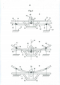
[0021] As figuras 1 e 2 mostram o tipo de quadros duplos de abaulamento (aqui, do tipo esqueleto) aos quais se refere a invenção. A figura 1 mostra um suporte compreendendo dois quadros, um rascunhador quase-plano 100 e um polidor 101 articulado com articulação central 102. O polidor compreende duas partes móveis 103 e 104 podendo girar em torno de uma articulação 102 (fala-se de “uma articulação”, mas cabe observar que se trata de um par de articulações, uma por borda longitudinal). O rascunhador compreende duas bordas laterais 105 e 106 e duas bordas longitudinais 107 e 108. As partes móveis do polidor compreendem, cada uma, uma borda lateral 109 e 110 do polidor. O polidor compreende igualmente duas bordas longitudinais, cada borda longitudinal sendo partilhada em duas partes situadas em cada parte móvel. Em a), a folha de vidro é suportada unicamente pelo rascunhador 100, o polidor estando aberto (partes móveis 103 e 104 não montadas) e inteiramente sob o nível da superfície de contato do rascunhador com a folha de vidro. A folha de vidro começa seu abaulamento no rascunhador. Visto de cima, o rascunhador é inteiramente inscrito no interior do polidor. Durante o abaulamento, o rascunhador desce e passa inteiramente ao interior do polidor, que se fecha. A folha de vidro passa, então, do rascunhador ao polidor. Em b), no fim do abaulamento, o polidor 101 é fechado (partes móveis 103 e 104 montadas) e sua superfície de contato com o vidro está inteiramente acima da superfície de contato do vidro com o rascunhador. Assim, o vidro não tem mais contato com o rascunhador 100.[0021] Figures 1 and 2 show the type of double bulging frames (here, of the skeleton type) to which the invention refers. Figure 1 shows a support comprising two frames, a
[0022] A figura 2 representa um suporte que compreende dois quadros, um rascunhador quase-plano 200 e um polidor 201 com duas articulações 202 e 203 (tendo assim, dois pares de articulações, cada borda longitudinal compreendendo duas articulações por borda longitudinal). As bordas longitudinais do polidor compreendendo as partes centrais entre as duas partes móveis. Em a), a folha de vidro é suportada unicamente pelo rascunhador 200, o polidor estando aberto (partes móveis 204 e 205 não montadas) e inteiramente sob o nível da superfície de contato do rascunhador com a folha de vidro. A folha de vidro começa seu abaulamento no rascunhador. Visto de cima, o rascunhador é inteiramente inscrito no interior do polidor. Durante o abaulamento, o rascunhador desce e passa inteiramente ao interior do polidor, que se fecha. A folha de vidro passa, então, do rascunhador ao polidor. Em b), no fim do abaulamento, o polidor 201 é fechado (partes móveis 204 e 205 montadas) e sua superfície de contato com o vidro está inteiramente acima da superfície de contato do vidro com o rascunhador. Assim, o vidro não tem mais contato com o rascunhador 200.[0022] Figure 2 represents a support comprising two frames, a
[0023] A figura 3 representa um suporte de abaulamento que compreende dois quadros do tipo esqueleto, um rascunhador plano 1 e um polidor 2 articulado em articulação central compreendendo duas partes móveis articuladas 3 e 4. As posições relativas dos dois esqueletos, bem como aquela das partes articuladas, são vistas em diferentes estados do abaulamento por gravidade de a) até d). Os dois esqueletos são do tipo anular e suportam a periferia de ao menos uma folha de vidro. O rascunhador se encontra no interior do polidor, visto de cima. Em a), a folha de vidro (não representada) repousa unicamente no rascunhador 1. Durante o abaulamento no rascunhador, a folha de vidro não corre o risco de tocar o polidor 2. De fato, ela se expande em sua região interna de modo que suas bordas subam e até mesmo se distanciem do polidor. Em b), o polidor está em vias de fechamento e suas duas partes articuladas 3 e 4 estão um pouco direcionadas para cima. Neste estado intermediário, a folha repousa ao mesmo tempo nas extremidades 5 e 6 do polidor, o que inclui as bordas laterais do polidor, e nas regiões centrais 7 das bordas longitudinais do rascunhador. O vidro está, então, protegido de qualquer contato com a articulação na direção vertical 9 desta. Em c), a articulação 8 do polidor 2 se fecha completamente e é possível ver ainda o rascunhador logo acima da articulação do polidor. A folha de vidro está, então, neste estado, suportada principalmente pelo polidor e ainda um pouco pelo rascunhador em suas regiões centrais 7 das bordas longitudinais e, em todo o tempo, na vertical da articulação. Em d), o polidor está no mesmo estado que em c), isto é, completamente fechado, mas o rascunhador 1 está retraído para baixo, de modo que a folha de vidro está inteiramente apoiada pelo polidor 2. O processo de a) até d) mostra como é possível que a folha de vidro não entre jamais em contato com a articulação 8 do polidor se este não estiver completamente fechado. De a) até d), houve um movimento contínuo relativo vertical do rascunhador e do polidor, fazendo passar o rascunhador através do polidor, acompanhado do fechamento do polidor.[0023] Figure 3 represents a bulging support that comprises two skeleton-type frames, a
[0024] A figura 4 representa um suporte de abaulamento que compreende dois esqueletos, um rascunhador plano 10 e um polidor 11 articulado compreendendo duas partes laterais móveis 12 e 13 de um lado a outro de partes centrais de bordas longitudinais do polidor. As posições relativas dos dois esqueletos, bem como a das partes articuladas são vistas em diferentes estágios do abaulamento por gravidade de a) até d). Os dois esqueletos são do tipo anular e suportam a periferia de ao menos uma folha de vidro. O rascunhador se encontra no interior do polidor, visto de cima. Em a), a folha de vidro repousa unicamente no rascunhador 1. Durante o abaulamento no rascunhador, a folha de vidro não corre o risco de tocar o polidor 2. De fato, ela se expande em sua região interna de modo que suas bordas subam e até mesmo se distanciem do polidor. Em b), o polidor está em vias de fechamento e suas duas partes móveis 12 e 13 estão um pouco direcionadas para cima. Neste estado intermediário, a folha repousa ao mesmo tempo nas extremidades 15 e 16 do polidor, o que inclui as bordas laterais do polidor, e nas regiões centrais 17 das bordas longitudinais do rascunhador 10. O vidro está, então, protegido de qualquer contato com as articulações nas verticais 20 e 21 destas. Em c), as articulações 18 e 19 do polidor 11 se fecham completamente e é possível ver ainda o rascunhador logo acima de tais articulações do polidor. A folha de vidro está, então, neste estado, suportada principalmente pelo polidor 11 e ainda pelo rascunhador em suas regiões centrais 17 das bordas longitudinais. Em d), o polidor 11 está no mesmo estado que em c), isto é, com articulações completamente fechadas, mas o rascunhador 10 está retraído para baixo e se encontra em baixo das articulações 18 e 19, de modo que a folha de vidro está inteiramente apoiada pelo polidor 11. O processo de a) até d) mostra como é possível que a folha de vidro não entre jamais em contato com as articulações 18 e 19 do polidor se este não estiver completamente fechado. De a) até d), houve um movimento contínuo relativo vertical do rascunhador e do polidor, fazendo passar o rascunhador através do polidor, acompanhado do fechamento do polidor.[0024] Figure 4 represents a bulging support comprising two skeletons, a
[0025] A figura 5 representa um suporte de abaulamento que compreende dois quadros do tipo esqueleto, um rascunhador plano 31 e um polidor 32 articulado em articulação central compreendendo duas partes móveis articuladas 33 e 34. As posições relativas dos dois esqueletos bem como aquela das partes articuladas são vistas em diferentes estados do abaulamento por gravidade de a) até c). Cada parte móvel compreende em seu comprimento um eixo de giro 35 e 36 cuja posição é fixa em relação ao chassi 37 do dispositivo (a fixação vertical do chassi é simbolizada pela representação da “terra”). Estes dois eixos de giro 35 e 36 não se movimentam, portanto, em altura. As partes móveis 33 e 34 podem se deslocar ligeiramente em relação a estes eixos de giro 35 e 36, graças aos buracos oblongos 50 e 51 arranjados nestas partes móveis em torno destes eixos de firo. As duas partes móveis 33 e 34 são, ainda, ligadas entre si por um outro eixo de giro 38 em posição central. Este eixo de giro 38 pode ser deslocado verticalmente em um guia 39 compreendendo um orifício oblongo 40 cujo comprimento é vertical. O eixo 38 pode se deslocar verticalmente no interior do buraco oblongo 40. O rascunhador 31 e o guia 39 são solidários entre si de forma fixa graças aos elementos de ligação 52 e 53. De a) até c), o princípio da substituição do rascunhador é aquele já explicado na figura 3. Em a), apenas o rascunhador porta a folha de vidro (não representada) e um primeiro abaulamento se dá sobre ele. Em seguida, o rascunhador começa a descer, o que permite ao eixo 38 igualmente descer sob efeito do peso das partes móveis perto do eixo 38. Esta baixa do eixo 38 faz subir as extremidades das partes móveis por giro em torno dos eixos de giro 35 e 36. As extremidades das partes móveis vêm, então, acima do rascunhador e recebem parcialmente a carga da folha de vidro. Neste estado (estado b) da figura 5), a folha de vidro repousa sobre as extremidades 41 e 42 das partes móveis, o que inclui as bordas laterais das partes móveis, e sobre a região central 43 das partes longitudinais do rascunhador. O polidor é fechado, as extremidades de suas partes móveis estando totalmente orientadas para cima. Batentes (não representados) solidários ao chassi marcam o fim da subida das extremidades das partes móveis, isto é, também o fim da descida das regiões 44 e 45 das partes móveis situadas entre o eixo de giro central 38 e os eixos de giro 35 e 36. Neste estado, o rascunhador se mantém acima da articulação central 38 fechada, protegendo desta forma o vidro à vertical 46 da articulação. O rascunhador pode continuar a descer acionando o guia 39. O eixo de giro 38 da articulação se mantém fixo em relação ao chassi. É o guia 39 que continua a descer, de modo que o eixo de giro central 38 se encontre acima do buraco oblongo no final do processo representado em c). O polidor 32 está, então, inteiramente acima do rascunhador 31.[0025] Figure 5 represents a bulging support that comprises two skeleton-type frames, a
Claims (16)
Applications Claiming Priority (3)
| Application Number | Priority Date | Filing Date | Title |
|---|---|---|---|
| FR1252038A FR2987833B1 (en) | 2012-03-06 | 2012-03-06 | ARTICULATION BOMBING SUPPORT |
| FR1252038 | 2012-03-06 | ||
| PCT/FR2013/050417 WO2013132174A1 (en) | 2012-03-06 | 2013-02-28 | Jointed bending mount |
Publications (1)
| Publication Number | Publication Date |
|---|---|
| BR112014021568B1 true BR112014021568B1 (en) | 2021-01-26 |
Family
ID=47997564
Family Applications (1)
| Application Number | Title | Priority Date | Filing Date |
|---|---|---|---|
| BR112014021568-5A BR112014021568B1 (en) | 2012-03-06 | 2013-02-28 | gravity bulging method of a sheet of glass on a support and gravity bulging support of a sheet of glass suitable for such a method |
Country Status (13)
| Country | Link |
|---|---|
| US (2) | US9193619B2 (en) |
| EP (1) | EP2822903B1 (en) |
| JP (1) | JP6339507B2 (en) |
| KR (1) | KR102048008B1 (en) |
| CN (1) | CN103748046B (en) |
| BR (1) | BR112014021568B1 (en) |
| CA (1) | CA2865691C (en) |
| EA (1) | EA025049B1 (en) |
| ES (1) | ES2566792T3 (en) |
| FR (1) | FR2987833B1 (en) |
| MX (1) | MX351025B (en) |
| PL (1) | PL2822903T3 (en) |
| WO (1) | WO2013132174A1 (en) |
Families Citing this family (6)
| Publication number | Priority date | Publication date | Assignee | Title |
|---|---|---|---|---|
| FR3017865A1 (en) | 2014-02-27 | 2015-08-28 | Saint Gobain | GRAVITY BOMBAGE ON DOUBLE SUPPORT |
| JP2016199410A (en) * | 2015-04-07 | 2016-12-01 | 株式會社塩山製作所 | Bending molding device and bending molding method of sheet glass |
| CN104860513B (en) * | 2015-04-15 | 2017-03-29 | 福耀玻璃工业集团股份有限公司 | A kind of vehicle glass bending mould |
| CN108602324B (en) | 2016-11-24 | 2021-09-10 | 法国圣戈班玻璃厂 | Method for producing a curved composite vitreous glass pane having a thin vitreous glass pane |
| CN206559732U (en) * | 2017-01-24 | 2017-10-13 | 深圳视爵光旭电子有限公司 | A kind of device and LED modules for bent plate |
| FR3093333B1 (en) | 2019-02-28 | 2023-01-20 | Saint Gobain | MANUFACTURE OF GLAZING WITH REDUCED EXTENSION STRESS |
Family Cites Families (11)
| Publication number | Priority date | Publication date | Assignee | Title |
|---|---|---|---|---|
| BE567133A (en) * | 1957-05-03 | |||
| FR2725194B1 (en) * | 1994-10-04 | 1996-10-31 | Saint Gobain Vitrage | METHOD AND DEVICE FOR THE BOMBING OF GLASS SHEETS |
| JP4671159B2 (en) * | 2000-07-19 | 2011-04-13 | 旭硝子株式会社 | Method and apparatus for bending glass plate |
| JP2004315311A (en) * | 2003-04-17 | 2004-11-11 | Sekisui Chem Co Ltd | Method for bending glass for laminated glass, method for manufacturing laminated glass, and laminated glass |
| FR2855168B1 (en) * | 2003-05-19 | 2007-03-30 | Saint Gobain | GRAVITY GLAZING OVER MULTIPLE MEDIA |
| CN2820857Y (en) * | 2005-04-30 | 2006-09-27 | 福耀玻璃工业集团股份有限公司 | Glass plate bending forming mould |
| CN2878377Y (en) * | 2005-11-16 | 2007-03-14 | 福耀玻璃工业集团股份有限公司 | Baking and bending formation mould for secondary forming glass board |
| CN2844116Y (en) * | 2005-11-18 | 2006-12-06 | 福耀玻璃工业集团股份有限公司 | Bended glass plate forming mould |
| FR2894955B1 (en) | 2005-12-20 | 2008-05-02 | Saint Gobain | GRAVITY GLASS BONDING DEVICE IN SEVERAL FORMS OF CONTROLLED SHAPE TRANSITIONAL SUPPORT |
| WO2009072530A1 (en) * | 2007-12-04 | 2009-06-11 | Asahi Glass Company, Limited | Glass pane bending and forming method, and glass pane bending and forming appratus |
| GB0810001D0 (en) * | 2008-06-02 | 2008-07-09 | Pilkington Group Ltd | Gravity bending glass sheets |
-
2012
- 2012-03-06 FR FR1252038A patent/FR2987833B1/en not_active Expired - Fee Related
-
2013
- 2013-02-28 PL PL13712304T patent/PL2822903T3/en unknown
- 2013-02-28 CA CA2865691A patent/CA2865691C/en active Active
- 2013-02-28 WO PCT/FR2013/050417 patent/WO2013132174A1/en active Application Filing
- 2013-02-28 EP EP13712304.8A patent/EP2822903B1/en active Active
- 2013-02-28 KR KR1020147024802A patent/KR102048008B1/en active IP Right Grant
- 2013-02-28 US US14/382,974 patent/US9193619B2/en active Active
- 2013-02-28 MX MX2014010558A patent/MX351025B/en active IP Right Grant
- 2013-02-28 BR BR112014021568-5A patent/BR112014021568B1/en not_active IP Right Cessation
- 2013-02-28 JP JP2014560426A patent/JP6339507B2/en active Active
- 2013-02-28 CN CN201380002769.0A patent/CN103748046B/en active Active
- 2013-02-28 EA EA201491637A patent/EA025049B1/en not_active IP Right Cessation
- 2013-02-28 ES ES13712304.8T patent/ES2566792T3/en active Active
-
2015
- 2015-11-20 US US14/947,607 patent/US9499427B2/en active Active
Also Published As
| Publication number | Publication date |
|---|---|
| CA2865691C (en) | 2020-04-21 |
| FR2987833A1 (en) | 2013-09-13 |
| MX351025B (en) | 2017-09-28 |
| US20160075588A1 (en) | 2016-03-17 |
| KR20140139494A (en) | 2014-12-05 |
| EP2822903A1 (en) | 2015-01-14 |
| CN103748046B (en) | 2016-06-22 |
| FR2987833B1 (en) | 2014-03-14 |
| PL2822903T3 (en) | 2016-07-29 |
| ES2566792T3 (en) | 2016-04-15 |
| US9193619B2 (en) | 2015-11-24 |
| EA025049B1 (en) | 2016-11-30 |
| EA201491637A1 (en) | 2016-05-31 |
| JP2015513519A (en) | 2015-05-14 |
| JP6339507B2 (en) | 2018-06-06 |
| EP2822903B1 (en) | 2016-02-24 |
| WO2013132174A1 (en) | 2013-09-12 |
| MX2014010558A (en) | 2014-12-05 |
| CN103748046A (en) | 2014-04-23 |
| CA2865691A1 (en) | 2013-09-12 |
| US20150059410A1 (en) | 2015-03-05 |
| US9499427B2 (en) | 2016-11-22 |
| KR102048008B1 (en) | 2019-11-22 |
Similar Documents
| Publication | Publication Date | Title |
|---|---|---|
| BR112014021568B1 (en) | gravity bulging method of a sheet of glass on a support and gravity bulging support of a sheet of glass suitable for such a method | |
| US7178759B2 (en) | Hinged door for aircraft landing gear | |
| US8286916B2 (en) | Retractable aerodynamic device permitting the control of the wake trajectory of an aircraft trap | |
| BRPI0610884A2 (en) | trap door opening and closing system for an aircraft landing gear | |
| BRPI0912893B1 (en) | gravity folding mold for folding glass sheets, apparatus for folding glass sheets, method of folding a glass sheet by gravity, and method of folding a glass sheet | |
| CN108001347A (en) | A kind of high vehicle-mounted HUD equipment of imaging definition | |
| JP2015513519A5 (en) | ||
| JP4876931B2 (en) | Natural ventilation window | |
| JP5560199B2 (en) | Gravity bending of glass plate | |
| TWI515358B (en) | Upright type air volume ventilation device | |
| JP2016102383A (en) | Window sash | |
| JP4876813B2 (en) | Natural ventilation window | |
| JP2014065486A5 (en) | ||
| CN103673248A (en) | Panel moving mechanism and air conditioner with the same | |
| CN205417635U (en) | Can slowly receive footboard that closes automatically | |
| JP5821193B2 (en) | Vertical constant air volume ventilator | |
| CN206668060U (en) | A kind of ventilation of vehicle window construction | |
| CN105108398B (en) | Axle housing assembly-welding device | |
| JP2005212540A (en) | Panel device for railroad vehicle | |
| US1853789A (en) | Rear seat windscreen | |
| CN105128643A (en) | Automobile sunshade mechanism | |
| JP2016199987A (en) | Window sash | |
| BR102019006409A2 (en) | IMPROVEMENTS INTRODUCED IN AIRCRAFT FLAP GEAR AND ITS RESPECTIVE OPERATION | |
| CN107867158A (en) | A kind of vehicle dormer window of convenient adjustment folding size | |
| JP2020093757A (en) | Platform door apparatus |
Legal Events
| Date | Code | Title | Description |
|---|---|---|---|
| B06F | Objections, documents and/or translations needed after an examination request according [chapter 6.6 patent gazette] | ||
| B06U | Preliminary requirement: requests with searches performed by other patent offices: procedure suspended [chapter 6.21 patent gazette] | ||
| B06A | Patent application procedure suspended [chapter 6.1 patent gazette] | ||
| B09A | Decision: intention to grant [chapter 9.1 patent gazette] | ||
| B16A | Patent or certificate of addition of invention granted [chapter 16.1 patent gazette] |
Free format text: PRAZO DE VALIDADE: 20 (VINTE) ANOS CONTADOS A PARTIR DE 28/02/2013, OBSERVADAS AS CONDICOES LEGAIS. |
|
| B21F | Lapse acc. art. 78, item iv - on non-payment of the annual fees in time |
Free format text: REFERENTE A 11A ANUIDADE. |
|
| B24J | Lapse because of non-payment of annual fees (definitively: art 78 iv lpi, resolution 113/2013 art. 12) |
Free format text: EM VIRTUDE DA EXTINCAO PUBLICADA NA RPI 2763 DE 19-12-2023 E CONSIDERANDO AUSENCIA DE MANIFESTACAO DENTRO DOS PRAZOS LEGAIS, INFORMO QUE CABE SER MANTIDA A EXTINCAO DA PATENTE E SEUS CERTIFICADOS, CONFORME O DISPOSTO NO ARTIGO 12, DA RESOLUCAO 113/2013. |