BR112012016873B1 - energy converter for converting high energy photon emissions into electrical energy - Google Patents
energy converter for converting high energy photon emissions into electrical energy Download PDFInfo
- Publication number
- BR112012016873B1 BR112012016873B1 BR112012016873-8A BR112012016873A BR112012016873B1 BR 112012016873 B1 BR112012016873 B1 BR 112012016873B1 BR 112012016873 A BR112012016873 A BR 112012016873A BR 112012016873 B1 BR112012016873 B1 BR 112012016873B1
- Authority
- BR
- Brazil
- Prior art keywords
- layers
- energy
- converter
- fact
- photon
- Prior art date
Links
- 239000000463 material Substances 0.000 claims abstract description 147
- 230000005611 electricity Effects 0.000 claims abstract description 8
- 239000011810 insulating material Substances 0.000 claims abstract description 5
- 229910052751 metal Inorganic materials 0.000 claims description 3
- 239000002184 metal Substances 0.000 claims description 3
- 229910052782 aluminium Inorganic materials 0.000 claims description 2
- XAGFODPZIPBFFR-UHFFFAOYSA-N aluminium Chemical compound [Al] XAGFODPZIPBFFR-UHFFFAOYSA-N 0.000 claims description 2
- 239000012774 insulation material Substances 0.000 claims description 2
- 229910044991 metal oxide Inorganic materials 0.000 claims description 2
- 150000004706 metal oxides Chemical class 0.000 claims description 2
- 239000003870 refractory metal Substances 0.000 claims description 2
- WFKWXMTUELFFGS-UHFFFAOYSA-N tungsten Chemical group [W] WFKWXMTUELFFGS-UHFFFAOYSA-N 0.000 claims description 2
- 229910052721 tungsten Inorganic materials 0.000 claims description 2
- 239000010937 tungsten Substances 0.000 claims description 2
- 238000006243 chemical reaction Methods 0.000 abstract description 33
- 238000000034 method Methods 0.000 abstract description 21
- 230000008901 benefit Effects 0.000 abstract description 7
- 210000004027 cell Anatomy 0.000 description 9
- 230000008569 process Effects 0.000 description 9
- 238000001816 cooling Methods 0.000 description 7
- 238000010521 absorption reaction Methods 0.000 description 6
- 210000002381 plasma Anatomy 0.000 description 6
- 239000002245 particle Substances 0.000 description 5
- 230000005012 migration Effects 0.000 description 4
- 238000013508 migration Methods 0.000 description 4
- 230000010287 polarization Effects 0.000 description 4
- 238000009825 accumulation Methods 0.000 description 3
- 230000009471 action Effects 0.000 description 3
- 238000005474 detonation Methods 0.000 description 3
- 239000002360 explosive Substances 0.000 description 3
- 230000005855 radiation Effects 0.000 description 3
- 239000003507 refrigerant Substances 0.000 description 3
- 238000001228 spectrum Methods 0.000 description 3
- 239000002915 spent fuel radioactive waste Substances 0.000 description 3
- 239000011800 void material Substances 0.000 description 3
- VYPSYNLAJGMNEJ-UHFFFAOYSA-N Silicium dioxide Chemical compound O=[Si]=O VYPSYNLAJGMNEJ-UHFFFAOYSA-N 0.000 description 2
- 230000004308 accommodation Effects 0.000 description 2
- 230000005540 biological transmission Effects 0.000 description 2
- 238000001514 detection method Methods 0.000 description 2
- 230000005264 electron capture Effects 0.000 description 2
- 230000004907 flux Effects 0.000 description 2
- 230000006870 function Effects 0.000 description 2
- 239000007789 gas Substances 0.000 description 2
- 238000010438 heat treatment Methods 0.000 description 2
- 239000001307 helium Substances 0.000 description 2
- 229910052734 helium Inorganic materials 0.000 description 2
- SWQJXJOGLNCZEY-UHFFFAOYSA-N helium atom Chemical compound [He] SWQJXJOGLNCZEY-UHFFFAOYSA-N 0.000 description 2
- 239000012212 insulator Substances 0.000 description 2
- 230000007246 mechanism Effects 0.000 description 2
- 230000004048 modification Effects 0.000 description 2
- 238000012986 modification Methods 0.000 description 2
- 239000003758 nuclear fuel Substances 0.000 description 2
- 230000000704 physical effect Effects 0.000 description 2
- 230000002285 radioactive effect Effects 0.000 description 2
- 239000002699 waste material Substances 0.000 description 2
- 241000252254 Catostomidae Species 0.000 description 1
- 230000005678 Seebeck effect Effects 0.000 description 1
- XUIMIQQOPSSXEZ-UHFFFAOYSA-N Silicon Chemical compound [Si] XUIMIQQOPSSXEZ-UHFFFAOYSA-N 0.000 description 1
- 230000001133 acceleration Effects 0.000 description 1
- 230000004075 alteration Effects 0.000 description 1
- 230000003321 amplification Effects 0.000 description 1
- 238000004458 analytical method Methods 0.000 description 1
- 238000005452 bending Methods 0.000 description 1
- 230000015556 catabolic process Effects 0.000 description 1
- 229910052681 coesite Inorganic materials 0.000 description 1
- 229910052906 cristobalite Inorganic materials 0.000 description 1
- 238000006731 degradation reaction Methods 0.000 description 1
- 230000001419 dependent effect Effects 0.000 description 1
- 238000010586 diagram Methods 0.000 description 1
- 230000000694 effects Effects 0.000 description 1
- 238000004146 energy storage Methods 0.000 description 1
- -1 for example Substances 0.000 description 1
- 230000004927 fusion Effects 0.000 description 1
- 238000009413 insulation Methods 0.000 description 1
- 230000003993 interaction Effects 0.000 description 1
- 230000014759 maintenance of location Effects 0.000 description 1
- 238000003199 nucleic acid amplification method Methods 0.000 description 1
- 230000003287 optical effect Effects 0.000 description 1
- 239000012857 radioactive material Substances 0.000 description 1
- 238000007665 sagging Methods 0.000 description 1
- 238000005204 segregation Methods 0.000 description 1
- 239000004065 semiconductor Substances 0.000 description 1
- 238000000926 separation method Methods 0.000 description 1
- 229910052710 silicon Inorganic materials 0.000 description 1
- 239000010703 silicon Substances 0.000 description 1
- 239000000377 silicon dioxide Substances 0.000 description 1
- 235000012239 silicon dioxide Nutrition 0.000 description 1
- 229910052682 stishovite Inorganic materials 0.000 description 1
- 230000005676 thermoelectric effect Effects 0.000 description 1
- 229910052905 tridymite Inorganic materials 0.000 description 1
Images


Classifications
-
- H—ELECTRICITY
- H01—ELECTRIC ELEMENTS
- H01L—SEMICONDUCTOR DEVICES NOT COVERED BY CLASS H10
- H01L31/00—Semiconductor devices sensitive to infrared radiation, light, electromagnetic radiation of shorter wavelength or corpuscular radiation and specially adapted either for the conversion of the energy of such radiation into electrical energy or for the control of electrical energy by such radiation; Processes or apparatus specially adapted for the manufacture or treatment thereof or of parts thereof; Details thereof
- H01L31/04—Semiconductor devices sensitive to infrared radiation, light, electromagnetic radiation of shorter wavelength or corpuscular radiation and specially adapted either for the conversion of the energy of such radiation into electrical energy or for the control of electrical energy by such radiation; Processes or apparatus specially adapted for the manufacture or treatment thereof or of parts thereof; Details thereof adapted as photovoltaic [PV] conversion devices
- H01L31/06—Semiconductor devices sensitive to infrared radiation, light, electromagnetic radiation of shorter wavelength or corpuscular radiation and specially adapted either for the conversion of the energy of such radiation into electrical energy or for the control of electrical energy by such radiation; Processes or apparatus specially adapted for the manufacture or treatment thereof or of parts thereof; Details thereof adapted as photovoltaic [PV] conversion devices characterised by at least one potential-jump barrier or surface barrier
- H01L31/072—Semiconductor devices sensitive to infrared radiation, light, electromagnetic radiation of shorter wavelength or corpuscular radiation and specially adapted either for the conversion of the energy of such radiation into electrical energy or for the control of electrical energy by such radiation; Processes or apparatus specially adapted for the manufacture or treatment thereof or of parts thereof; Details thereof adapted as photovoltaic [PV] conversion devices characterised by at least one potential-jump barrier or surface barrier the potential barriers being only of the PN heterojunction type
- H01L31/0725—Multiple junction or tandem solar cells
-
- G—PHYSICS
- G01—MEASURING; TESTING
- G01T—MEASUREMENT OF NUCLEAR OR X-RADIATION
- G01T1/00—Measuring X-radiation, gamma radiation, corpuscular radiation, or cosmic radiation
- G01T1/16—Measuring radiation intensity
- G01T1/28—Measuring radiation intensity with secondary-emission detectors
-
- G—PHYSICS
- G21—NUCLEAR PHYSICS; NUCLEAR ENGINEERING
- G21H—OBTAINING ENERGY FROM RADIOACTIVE SOURCES; APPLICATIONS OF RADIATION FROM RADIOACTIVE SOURCES, NOT OTHERWISE PROVIDED FOR; UTILISING COSMIC RADIATION
- G21H1/00—Arrangements for obtaining electrical energy from radioactive sources, e.g. from radioactive isotopes, nuclear or atomic batteries
- G21H1/04—Cells using secondary emission induced by alpha radiation, beta radiation, or gamma radiation
-
- G—PHYSICS
- G21—NUCLEAR PHYSICS; NUCLEAR ENGINEERING
- G21H—OBTAINING ENERGY FROM RADIOACTIVE SOURCES; APPLICATIONS OF RADIATION FROM RADIOACTIVE SOURCES, NOT OTHERWISE PROVIDED FOR; UTILISING COSMIC RADIATION
- G21H1/00—Arrangements for obtaining electrical energy from radioactive sources, e.g. from radioactive isotopes, nuclear or atomic batteries
- G21H1/06—Cells wherein radiation is applied to the junction of different semiconductor materials
-
- H—ELECTRICITY
- H01—ELECTRIC ELEMENTS
- H01L—SEMICONDUCTOR DEVICES NOT COVERED BY CLASS H10
- H01L31/00—Semiconductor devices sensitive to infrared radiation, light, electromagnetic radiation of shorter wavelength or corpuscular radiation and specially adapted either for the conversion of the energy of such radiation into electrical energy or for the control of electrical energy by such radiation; Processes or apparatus specially adapted for the manufacture or treatment thereof or of parts thereof; Details thereof
- H01L31/02—Details
- H01L31/0232—Optical elements or arrangements associated with the device
-
- H—ELECTRICITY
- H01—ELECTRIC ELEMENTS
- H01L—SEMICONDUCTOR DEVICES NOT COVERED BY CLASS H10
- H01L31/00—Semiconductor devices sensitive to infrared radiation, light, electromagnetic radiation of shorter wavelength or corpuscular radiation and specially adapted either for the conversion of the energy of such radiation into electrical energy or for the control of electrical energy by such radiation; Processes or apparatus specially adapted for the manufacture or treatment thereof or of parts thereof; Details thereof
- H01L31/0248—Semiconductor devices sensitive to infrared radiation, light, electromagnetic radiation of shorter wavelength or corpuscular radiation and specially adapted either for the conversion of the energy of such radiation into electrical energy or for the control of electrical energy by such radiation; Processes or apparatus specially adapted for the manufacture or treatment thereof or of parts thereof; Details thereof characterised by their semiconductor bodies
- H01L31/0256—Semiconductor devices sensitive to infrared radiation, light, electromagnetic radiation of shorter wavelength or corpuscular radiation and specially adapted either for the conversion of the energy of such radiation into electrical energy or for the control of electrical energy by such radiation; Processes or apparatus specially adapted for the manufacture or treatment thereof or of parts thereof; Details thereof characterised by their semiconductor bodies characterised by the material
-
- H—ELECTRICITY
- H01—ELECTRIC ELEMENTS
- H01L—SEMICONDUCTOR DEVICES NOT COVERED BY CLASS H10
- H01L31/00—Semiconductor devices sensitive to infrared radiation, light, electromagnetic radiation of shorter wavelength or corpuscular radiation and specially adapted either for the conversion of the energy of such radiation into electrical energy or for the control of electrical energy by such radiation; Processes or apparatus specially adapted for the manufacture or treatment thereof or of parts thereof; Details thereof
- H01L31/0248—Semiconductor devices sensitive to infrared radiation, light, electromagnetic radiation of shorter wavelength or corpuscular radiation and specially adapted either for the conversion of the energy of such radiation into electrical energy or for the control of electrical energy by such radiation; Processes or apparatus specially adapted for the manufacture or treatment thereof or of parts thereof; Details thereof characterised by their semiconductor bodies
- H01L31/0352—Semiconductor devices sensitive to infrared radiation, light, electromagnetic radiation of shorter wavelength or corpuscular radiation and specially adapted either for the conversion of the energy of such radiation into electrical energy or for the control of electrical energy by such radiation; Processes or apparatus specially adapted for the manufacture or treatment thereof or of parts thereof; Details thereof characterised by their semiconductor bodies characterised by their shape or by the shapes, relative sizes or disposition of the semiconductor regions
-
- H—ELECTRICITY
- H01—ELECTRIC ELEMENTS
- H01L—SEMICONDUCTOR DEVICES NOT COVERED BY CLASS H10
- H01L31/00—Semiconductor devices sensitive to infrared radiation, light, electromagnetic radiation of shorter wavelength or corpuscular radiation and specially adapted either for the conversion of the energy of such radiation into electrical energy or for the control of electrical energy by such radiation; Processes or apparatus specially adapted for the manufacture or treatment thereof or of parts thereof; Details thereof
- H01L31/08—Semiconductor devices sensitive to infrared radiation, light, electromagnetic radiation of shorter wavelength or corpuscular radiation and specially adapted either for the conversion of the energy of such radiation into electrical energy or for the control of electrical energy by such radiation; Processes or apparatus specially adapted for the manufacture or treatment thereof or of parts thereof; Details thereof in which radiation controls flow of current through the device, e.g. photoresistors
- H01L31/085—Semiconductor devices sensitive to infrared radiation, light, electromagnetic radiation of shorter wavelength or corpuscular radiation and specially adapted either for the conversion of the energy of such radiation into electrical energy or for the control of electrical energy by such radiation; Processes or apparatus specially adapted for the manufacture or treatment thereof or of parts thereof; Details thereof in which radiation controls flow of current through the device, e.g. photoresistors the device being sensitive to very short wavelength, e.g. X-ray, Gamma-rays
-
- H—ELECTRICITY
- H01—ELECTRIC ELEMENTS
- H01L—SEMICONDUCTOR DEVICES NOT COVERED BY CLASS H10
- H01L31/00—Semiconductor devices sensitive to infrared radiation, light, electromagnetic radiation of shorter wavelength or corpuscular radiation and specially adapted either for the conversion of the energy of such radiation into electrical energy or for the control of electrical energy by such radiation; Processes or apparatus specially adapted for the manufacture or treatment thereof or of parts thereof; Details thereof
- H01L31/08—Semiconductor devices sensitive to infrared radiation, light, electromagnetic radiation of shorter wavelength or corpuscular radiation and specially adapted either for the conversion of the energy of such radiation into electrical energy or for the control of electrical energy by such radiation; Processes or apparatus specially adapted for the manufacture or treatment thereof or of parts thereof; Details thereof in which radiation controls flow of current through the device, e.g. photoresistors
- H01L31/10—Semiconductor devices sensitive to infrared radiation, light, electromagnetic radiation of shorter wavelength or corpuscular radiation and specially adapted either for the conversion of the energy of such radiation into electrical energy or for the control of electrical energy by such radiation; Processes or apparatus specially adapted for the manufacture or treatment thereof or of parts thereof; Details thereof in which radiation controls flow of current through the device, e.g. photoresistors characterised by at least one potential-jump barrier or surface barrier, e.g. phototransistors
- H01L31/115—Devices sensitive to very short wavelength, e.g. X-rays, gamma-rays or corpuscular radiation
-
- Y—GENERAL TAGGING OF NEW TECHNOLOGICAL DEVELOPMENTS; GENERAL TAGGING OF CROSS-SECTIONAL TECHNOLOGIES SPANNING OVER SEVERAL SECTIONS OF THE IPC; TECHNICAL SUBJECTS COVERED BY FORMER USPC CROSS-REFERENCE ART COLLECTIONS [XRACs] AND DIGESTS
- Y02—TECHNOLOGIES OR APPLICATIONS FOR MITIGATION OR ADAPTATION AGAINST CLIMATE CHANGE
- Y02E—REDUCTION OF GREENHOUSE GAS [GHG] EMISSIONS, RELATED TO ENERGY GENERATION, TRANSMISSION OR DISTRIBUTION
- Y02E10/00—Energy generation through renewable energy sources
- Y02E10/50—Photovoltaic [PV] energy
- Y02E10/542—Dye sensitized solar cells
Abstract
CONVERSOR DE ENERGIA DESTINADO À CONVERSÃO DE EMISSÕES DE FÓTONS DE ELEVADA ENERGIA EM ENERGIA ELÉTRICA Sistema e métodos para a conversão de energia advinda de fótons de elevada energia em eletricidade que fazem uso de uma série de materiais contendo diferenciadas cargas atômicas para levar vantagem quanto a emissão de uma ampla multiplicidade de elétrons através de um único fóton contendo elevada energia via uma cascata de emissões de elétrons Auger. Em um tipo de modalidade, um conversor de fóton de elevada energia vem a incluir, preferencialmente, uma bolacha em escala nanométrica depositada linearmente concebida a partir de camadas de um primeiro material comprimido entre camadas de um segundo material apresentando um número de carga atômica diferindo do número de carga atômica do primeiro material. Em outro tipo de modalidade, as camadas em escala nanométrica são configuradas em uma configuração em formato de concha ou tubular e/ou incluem camadas de um terceiro material isolante.ENERGY CONVERTER FOR THE CONVERSION OF HIGH ENERGY PHOTON EMISSIONS TO ELECTRIC ENERGY System and methods for converting energy from high energy photons into electricity that make use of a series of materials containing different atomic charges to take advantage of emission of a wide multiplicity of electrons through a single photon containing high energy via a cascade of Auger electron emissions. In one type of modality, a high-energy photon converter preferably includes a wafer on a nanoscale deposited linearly conceived from layers of a first compressed material between layers of a second material showing an atomic charge number differing from the atomic charge number of the first material. In another type of modality, the nanometer scale layers are configured in a shell or tubular configuration and / or include layers of a third insulating material.
Description
As modalidades descritas neste relatório relacionam-se, genericamente, a conversão de energia fotônica e, mais particularmente, a sistemas e métodos que visam facilitar a conversão de energia advinda de fótons de alta energia em eletricidade.The modalities described in this report are generally related to the conversion of photonic energy and, more particularly, to systems and methods that aim to facilitate the conversion of energy from high energy photons into electricity.
Existem muitos dispositivos bastante conhecidos que fazem a conversão elétrica de energia dos fótons na faixa ótica, tal como, por exemplo, células fotovoltaicas (“painéis solares”). Esses dispositivos, em geral, constituem-se em pelo menos dois materiais (ou seja, semicondutores a base de silício) contendo diferenciadas propriedades físicas, tal como diferentes afinidades eletrônicas (consulte, The Physics of Solar Cells, P. Wurfel, Primeira Edição, Wiley-VCH (2004)). Quando um dos materiais vem a ser iluminado pela luz solar, os fótons solares excitam os fótons-elétrons a partir de uma faixa de valência para uma faixa condutora, caracterizando uma mobilidade elétrica. O intervalo de energia entre as faixas de valência e condução dá-se numa ordem típica de um elétron-volt, algo semelhante a energia dos fótons solares incidentes. O posicionamento de dois materiais apresentando diferenciadas afinidades eletrônicas dá surgimento a uma tensão elétrica ao longo da fronteira limite do material, a qual pode ser derivada para emprego de energia elétrica.There are many well-known devices that make the electrical conversion of photons energy in the optical range, such as, for example, photovoltaic cells ("solar panels"). These devices, in general, consist of at least two materials (that is, silicon-based semiconductors) containing different physical properties, such as different electronic affinities (see, The Physics of Solar Cells, P. Wurfel, First Edition, Wiley-VCH (2004)). When one of the materials is illuminated by sunlight, solar photons excite electron photons from a valence band to a conductive band, characterizing an electrical mobility. The energy interval between the valence and conduction bands occurs in an order typical of an electron volt, something similar to the energy of the incident solar photons. The positioning of two materials with differentiated electronic affinities gives rise to an electrical voltage along the material's boundary boundary, which can be derived for the use of electrical energy.
Entretanto não se conhece dispositivos voltados para a conversão da energia em eletricidade a partir do emprego de fótons operando em um regime de fótons de alta energia, tal como, os raios XUV, X e gama. Tais dispositivos podem ser utilizados em uma ampla gama de aplicações - por exemplo, tais dispositivos podem ser utilizados como conversores de energia voltados para a conversão de fótons de alta energia emitidos por meio de materiais radioativos, tais como, por exemplo, barras gastas de combustível nuclear, emitidos por meio de fontes de detonação, tais como, por exemplo, explosivos, e emitidos através de plasmas e feixes de partículas aceleradas sob temperaturas elevadas, e na forma de dispositivos destinados a aplicações espaciais sob modo de fontes de força, blindagem e coisas do gênero. Surgem dificuldades na provisão de tais tipos de dispositivos a partir da grande penetrabilidade dos fótons de alta energia através da matéria, o que advém da consequência de uma interação muito menor de tais fótons com a matéria quando comparando-se com a luz visível, e a partir do fato de que para a maioria dos materiais, o caminho médio livre dos elétrons representa, tipicamente, muitas ordens de magnitude mais curta do que o caminho médio livre dos fótons de alta energia. Como consequência desta disparidade nos caminhos médios livres, os elétrons emitidos a partir de um átomo em um material empregado para capturar fótons de alta energia tendem a sucumbir quando recombinados, enquanto as suas energias vem a serem convertidas em calor no interior do material retido no fóton de alta energia.However, there are no known devices dedicated to the conversion of energy into electricity using photons operating in a high energy photon regime, such as XUV, X and gamma rays. Such devices can be used in a wide range of applications - for example, such devices can be used as energy converters aimed at the conversion of high energy photons emitted by means of radioactive materials, such as, for example, spent fuel rods. nuclear, emitted by means of detonation sources, such as, for example, explosives, and emitted by plasmas and beams of particles accelerated under high temperatures, and in the form of devices intended for space applications in the form of power sources, shielding and things like that. Difficulties arise in the provision of such types of devices due to the high penetrability of high energy photons through matter, which results from the consequence of a much smaller interaction of such photons with matter when compared with visible light, and the from the fact that for most materials, the average free path of electrons typically represents many orders of magnitude shorter than the average free path of high-energy photons. As a consequence of this disparity in the free medium paths, electrons emitted from an atom in a material used to capture high-energy photons tend to succumb when recombined, while their energies are converted into heat inside the material trapped in the photon. high energy.
Desse modo, é desejável se proporcionar com sistemas e métodos que viriam a facilitar a conversão de energia em energia elétrica a partir dos fótons de alta energia.Thus, it is desirable to provide systems and methods that would facilitate the conversion of energy into electrical energy from high energy photons.
As modalidades descritas neste relatório são direcionadas para a conversão de energia em energia elétrica a partir dos fótons de alta energia. O princípio norteando as modalidades disponibilizadas por este relatório se baseiam na ejeção de elétrons a partir de um átomo (incluindo-se a ejeção de elétrons profundamente depositados na estrutura interna a partir de um átomo de materiais com elevado número atômico (Z-elevado)) através de fótons de alta energia. Os elétrons ejetados conduzem energia cinética, o que pode levar a migração dos elétrons ejetados em diferentes regiões de um dispositivo aonde o acúmulo dos elétrons ejetados pode vir a criar um potencial elétrico que pode então acionar um circuito elétrico externo. O espectro de fótons de interesse inclui fótons na intervalo não-visível inclu- indo-se, porém sem qualquer restrição, a faixa dos raios XUV, raios X, raios gama e elementos do gênero.The modalities described in this report are aimed at converting energy into electrical energy from high energy photons. The principle guiding the modalities provided by this report are based on the ejection of electrons from an atom (including the ejection of electrons deeply deposited in the internal structure from an atom of materials with a high atomic number (high Z)) through high energy photons. The ejected electrons conduct kinetic energy, which can lead to the migration of ejected electrons in different regions of a device where the accumulation of ejected electrons can create an electrical potential that can then trigger an external electrical circuit. The spectrum of photons of interest includes photons in the non-visible range including, but without any restriction, the range of XUV rays, X-rays, gamma rays and elements of the genre.
Os sistemas e métodos disponibilizados através deste relatório fazem uso de uma série de materiais contendo diferentes cargas atômicas para aproveitar da vantagem da emissão de uma imensa multiplicidade de elétrons provendo de um único fóton de alta energia via uma cascata de emissões de elétrons Auger. Em um tipo de modalidade, um conversor de fóton de alta energia inclui, preferencialmente, uma bolacha em escala nanométrica depositada linearmente, formada a partir de uma primeira pluralidade de camadas de um material voltado a absorção de fótons de alta energia e emitindo elétrons combinados a uma segunda pluralidade de camadas de outros tipos de materiais voltados a absorção ou coleta de elétrons. O material referente a segunda pluralidade de camadas apresenta um número de carga atômica diferente do número de carga atômica do material referente a primeira pluralidade de camadas. A primeira e segunda pluralidade de camadas são empilhadas, preferencialmente, de forma lateral, lado a lado (ou seja, face-a-face), interpondo-se uma com a outra, e sendo orientadas junto a um ângulo raso (pequeno) em relação a direção de propagação dos fótons de alta energia. Em outro tipo de modalidade, as camadas em escalas nanométricas são configuradas em um tipo de configuração em forma de concha ou tubular. Em ainda outro tipo de modalidade, as camadas incluem uma terceira pluralidade de camadas contendo material isolante.The systems and methods made available through this report make use of a series of materials containing different atomic charges to take advantage of the emission of an immense multiplicity of electrons coming from a single high-energy photon via a cascade of Auger electron emissions. In a type of modality, a high-energy photon converter preferably includes a wafer on a nanometric scale deposited linearly, formed from a first plurality of layers of a material aimed at absorbing high-energy photons and emitting combined electrons at a second plurality of layers of other types of materials aimed at absorbing or collecting electrons. The material referring to the second plurality of layers has a different atomic charge number than the atomic charge number of the material referring to the first plurality of layers. The first and second plurality of layers are preferably stacked sideways, side by side (that is, face-to-face), interposing with each other, and being oriented at a shallow (small) angle in the direction of propagation of high energy photons. In another type of modality, the layers in nanometric scales are configured in a type of configuration in the form of a shell or tubular. In yet another type of embodiment, the layers include a third plurality of layers containing insulating material.
Os sistemas e métodos descritos por este relatório podem ser utilizados em uma ampla faixa de aplicações - desde detecção e absorção de energia, até conversão de energia de fótons de alta energia presentes em aceleradores de partículas até fontes de matéria extremamente em fusão (como plasmas sob altas temperaturas) e/ou fontes de detonação emitindo milhões de fótons de alta energia (tais como explosivos), energia capturada a partir de emissões de refugos nucleares radioativos (tais como barras gastas de combustível nuclear), e aplicações espaciais (tais como fontes de força, blindagem, e elementos do gênero), assim como outros tipos de aplicações prontamente identificáveis aos técnicos da área.The systems and methods described in this report can be used in a wide range of applications - from energy detection and absorption, to energy conversion from high energy photons present in particle accelerators to extremely fusing sources of matter (such as plasmas under high temperatures) and / or detonation sources emitting millions of high-energy photons (such as explosives), energy captured from radioactive nuclear waste emissions (such as spent nuclear fuel rods), and space applications (such as strength, armor, and similar elements), as well as other types of applications readily identifiable to technicians in the field.
Outros tipos de sistemas, métodos, características e vantagens das modalidades de exemplo tornar-se-ão imediatamente evidentes aos especialistas mediante uma análise das figuras a seguir e da descrição detalhada que se segue.Other types of systems, methods, characteristics and advantages of the example modalities will become immediately apparent to specialists through an analysis of the figures below and the detailed description that follows.
Os detalhes referentes as modalidades de exemplo, incluindo-se a estrutura e operação, podem ser capturados em parte através do estudo das figuras de acompanhamento, aonde numerais de referência idênticos representam partes idênticas. Os componentes presentes nas figuras não se apresentam necessariamente em escala, com ênfase sendo dada na ilustração dos princípios da invenção. Além disso, todas as ilustrações são voltadas para explicação dos conceitos, aonde os tamanhos, formatos e outros atributos detalhados relativos podem ser ilustrados esquematicamente ao invés de um rigor preciso ou literário.The details regarding the example modalities, including the structure and operation, can be captured in part by studying the accompanying figures, where identical reference numerals represent identical parts. The components present in the figures do not necessarily appear in scale, with emphasis being given to illustrating the principles of the invention. In addition, all illustrations are aimed at explaining concepts, where sizes, shapes and other detailed detailed attributes can be illustrated schematically instead of precise or literary rigor.
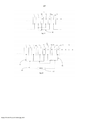
A Figura 1A consiste em uma vista esquemática de um elemento de conversão de fóton de alta energia em escala nanométrica depositado linearmente.Figure 1A consists of a schematic view of a high-energy nanometer-scale photon conversion element deposited linearly.
A Figura 1B consiste em uma vista esquemática de um elemento alternativo de fóton de alta energia em escala nanométrica depositado linearmente.Figure 1B consists of a schematic view of an alternative high-energy photon element on a nanometric scale deposited linearly.
A Figura 1C consiste em uma vista esquemática de um conversor de fóton de alta energia compreendendo de uma disposição de elementos de conversão em escala nanométrica depositados linearmente mostrados na Figura 1A.Figure 1C consists of a schematic view of a high-energy photon converter comprising an array of linearly deposited nano-scale conversion elements shown in Figure 1A.
A Figura 1D consiste em uma vista esquemática de um conversor de fóton de alta energia compreendendo de uma disposição de elementos de conversão em escala nanométrica depositados linearmente mostrados na Figura 1B.Figure 1D consists of a schematic view of a high-energy photon converter comprising an array of linearly deposited nano-scale conversion elements shown in Figure 1B.
A Figura 1E consiste em uma vista esquemática de um circuito de conversão de fóton de alta energia.Figure 1E consists of a schematic view of a high-energy photon conversion circuit.
A Figura 1F consiste em uma vista esquemática de um circuito de conversão de fóton de alta energia alternativo acoplado a um circuito externo contendo uma carga.Figure 1F consists of a schematic view of an alternative high-energy photon conversion circuit coupled to an external circuit containing a charge.
A Figura 2A consiste em uma vista em perspectiva de um elemento de conversão de fóton de alta energia em escala nanométrica depositado cilindricamente.Figure 2A consists of a perspective view of a high energy photon converting element on a nanometric scale deposited cylindrically.
A Figura 2B consiste em uma vista em perspectiva de um elemento alternativo de conversão de fóton de alta energia em escala nanométrica depositado cilindricamente.Figure 2B consists of a perspective view of an alternative element for converting high-energy photons to a nanometric scale deposited cylindrically.
A Figura 2C consiste em uma vista em perspectiva de um conversor de fóton de alta energia compreendendo de uma disposição de elementos de conversão em escala nanométrica depositados cilindricamente mostrados na Figura 2A.Figure 2C consists of a perspective view of a high-energy photon converter comprising an array of cylindrically deposited nanometric scale conversion elements shown in Figure 2A.
A Figura 2D consiste em uma vista de extremidade de um conversor de fóton de alta energia compreendendo de uma disposição de elementos de conversão em escala na- nométrica depositados cilindricamente mostrados na Figura 2B.Figure 2D consists of an end view of a high-energy photon converter comprising an array of cylindrically deposited naonometric scale conversion elements shown in Figure 2B.
As Figuras 2E, 2F e 2G consistem em vistas de extremidade de conversores de fótons de alta energia contendo configurações geométricas alternativas.Figures 2E, 2F and 2G consist of end views of high-energy photon converters containing alternative geometric configurations.
A Figura 3 consiste em um diagrama ilustrando as características de propagação dos fótons incidentes de alta energia v e das características de migração dos elétrons e que vem a ser ejetados de seus átomos em uma camada de material por meio dos fótons incidentes de alta energia v.Figure 3 consists of a diagram illustrating the propagation characteristics of the incident high-energy photons v and the migration characteristics of the electrons, which are ejected from their atoms in a layer of material by means of the incident high-energy photons v.
A Figura 4A consiste em uma vista esquemática de uma telha de conversão contendo uma pluralidade de camadas empilhadas linearmente.Figure 4A consists of a schematic view of a conversion tile containing a plurality of layers stacked linearly.
A Figura 4B consiste em uma vista em perspectiva de uma telha de conversão contendo uma pluralidade de camadas empilhadas linearmente.Figure 4B consists of a perspective view of a conversion tile containing a plurality of layers stacked linearly.
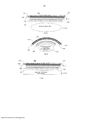
A Figura 5 consiste em uma vista esquemática apresentando um conjunto de telhas detalhadas pelas Figuras 4A e 4B posicionadas ao longo de uma superfície de conformação interceptando e se apresentando substancialmente perpendicular ao fluxo de fótons emitido a partir de uma fonte de fluxo de fótons.Figure 5 consists of a schematic view showing a set of tiles detailed by Figures 4A and 4B positioned along a forming surface intersecting and substantially perpendicular to the photon flow emitted from a photon flow source.
As Figuras 6A, 6B e 6C consistem em vistas esquemáticas apresentando um conjunto de telhas descrito através das Figuras 4A e 4B posicionadas ao longo das superfícies de conformação interceptando e se apresentando substancialmente perpendiculares aos fluxos de fótons emitidos a partir de fontes de fluxos de fótons.Figures 6A, 6B and 6C consist of schematic views showing a set of tiles described through Figures 4A and 4B positioned along the forming surfaces intersecting and substantially perpendicular to the photon fluxes emitted from photon flux sources.
Deve ser observado que os elementos de estruturas ou funções semelhantes são, em geral, representados por numerais de referência idênticos destinados a propósitos ilustrativos ao longo das figuras. Deve ser observado ainda que as figuras se destinam tão somente a facilitarem a descrição das modalidades preferidas.It should be noted that elements of similar structures or functions are, in general, represented by identical reference numerals intended for illustrative purposes throughout the figures. It should also be noted that the figures are only intended to facilitate the description of the preferred modalities.
Cada uma das características e ensinamentos adicionais descritos adiante podem ser utilizados separadamente ou em conjunto com outras características e ensinamentos destinados a produção de sistemas e métodos voltados para a conversão de energia advinda de fótons de alta energia em eletricidade. Exemplos representativos da presente invenção, exemplos que fazem uso de muitas dessas características e ensinamentos adicionais, tanto separadamente quanto em combinação, passarão a serem descritos em maiores detalhes tendo como referência os desenhos anexos. Esta descrição detalhada destina-se meramente a instruir um técnico da área com detalhes adicionais para a prática dos aspectos preferidos dos ensinamentos presentes, não pretendendo haver restrições quanto ao escopo da invenção. Portanto, as combinações de características e etapas descritas na descrição detalhada a seguir podem não serem necessárias para a prática da invenção no seu sentido mais amplo, estando incluídas meramente para atender exemplos representativos de descrições particulares dos presentes ensinamentos.Each of the additional features and teachings described below can be used separately or in conjunction with other features and teachings aimed at producing systems and methods aimed at converting energy from high energy photons into electricity. Representative examples of the present invention, examples that make use of many of these features and additional teachings, both separately and in combination, will be described in greater detail with reference to the accompanying drawings. This detailed description is intended merely to instruct a technician in the field with additional details for the practice of the preferred aspects of the present teachings, without pretending to be restrictions on the scope of the invention. Therefore, the combinations of features and steps described in the detailed description below may not be necessary for the practice of the invention in its broadest sense, being included merely to serve representative examples of particular descriptions of the present teachings.
Além disso, diversas características dos exemplos representativos e das reivindicações dependentes podem ser combinadas em maneiras que não são especificamente e explicitamente enumeradas de forma a fornecerem com modalidades adicionais úteis referentes aos ensinamentos presentes. Além disso, observa-se expressamente que todas as características descritas no relatório e/ou nas reivindicações destinam-se a apresentarem descrições separadas e independentes umas das outras sob propósito de ter-se uma descrição original, assim como com a finalidade de vir a se restringir a matéria em questão reivindicada independentemente das composições das características nas modalidades e/ou reivindicações. Ainda se observa expressamente que todas as faixas de valores ou indicações de grupos de entidades descrevem cada possível valor intermediário ou entidade intermediária voltados para a descrição original, assim como para fins de restringir-se a matéria em questão reivindicada.In addition, several characteristics of the representative examples and dependent claims can be combined in ways that are not specifically and explicitly enumerated in order to provide with additional useful modalities referring to the present teachings. In addition, it is expressly noted that all features described in the report and / or in the claims are intended to present separate and independent descriptions from each other for the purpose of having an original description, as well as for the purpose of becoming restrict the matter in question claimed regardless of the composition of the features in the modalities and / or claims. It is also expressly observed that all ranges of values or indications of groups of entities describe each possible intermediate value or intermediate entity focused on the original description, as well as for the purpose of restricting the matter in question.
As modalidades descritas neste relatório são direcionadas a conversão de energia advinda de fótons de alta energia (tais como fótons contendo energia preferencialmente na faixa indo de em torno de 100 eV ou mais) em eletricidade. O princípio regendo as modalidades se baseia na ejeção de elétrons a partir de um átomo (incluindo-se a ejeção de elétrons profundamente depositados na estrutura interna a partir de um átomo de materiais de elevados números atômicos (Z-elevado)) através de fótons de alta energia. Os elétrons ejetados conduzem energia cinética, o que pode levar a migração de elétrons ejetados em diferentes regiões de um dispositivo, aonde o acúmulo de elétrons ejetado pode vir a criar um potencial elétrico que pode ser derivado para acionar um circuito elétrico externo. O espectro de fótons de interesse inclui fótons preferencial mente do regime não-visível, incluindo os raios XUV, raios X e raios gama e elementos do gênero, porém sem ficar-se restrito as mesmas. A energia advinda de tais fótons compreende ordens de magnitudes maiores e, portanto, a margem para a termalização é muito mais abrangente (o coeficiente teórico de Carnot é próximo da unidade), do que a energia advinda dos fótons no regime visível. Em função da alta energia incidente de fóton, em geral de 100 eV ou maior, os sistemas e métodos descritos neste relatório tem a capacidade de extraordinária elevada eficiência de conversão de energia, em comparação com outros tipos de conversores padrões de energia de fótons, tais como dispositivos fotoelétricos (ou seja, painéis solares), ou dispositivos baseados no efeito termoelétrico (por exemplo, efeito de Seebeck).The modalities described in this report are aimed at converting energy from high energy photons (such as photons containing energy preferably in the range of around 100 eV or more) into electricity. The principle governing the modalities is based on the ejection of electrons from an atom (including the ejection of electrons deeply deposited in the internal structure from an atom of materials of high atomic numbers (high Z)) through photons of high energy. The ejected electrons conduct kinetic energy, which can lead to the migration of ejected electrons in different regions of a device, where the accumulation of ejected electrons can create an electrical potential that can be derived to drive an external electrical circuit. The spectrum of photons of interest includes photons preferably from the non-visible regime, including XUV rays, X rays and gamma rays and elements of the genre, but without being restricted to them. The energy from such photons comprises orders of greater magnitudes and, therefore, the margin for thermalization is much more comprehensive (Carnot's theoretical coefficient is close to the unit), than the energy from photons in the visible regime. Due to the high incident photon energy, generally 100 eV or greater, the systems and methods described in this report have the capacity for extraordinarily high energy conversion efficiency, compared to other types of standard photon energy converters, such as such as photoelectric devices (ie solar panels), or devices based on the thermoelectric effect (for example, Seebeck effect).
Conforme discutido em maiores detalhes adiante, tem-se a apresentação dos sistemas e métodos utilizados para delimitações deste canal potencialmente efetivo em ganho de elevado das energias advindas de fótons de alta energia transformadas em um formato apropriado de energia elétrica, que pode vir a ser derivada para acionamento de um circuito externo, e, desse modo abranger uma vasta área de aplicações, incluindo-se aquelas aonde fortes campos magnéticos encontram-se presentes (de modo que a dinâmica dos elétrons seja caracterizada pelo movimento giroscópico ao longo dos campos magnéticos). Culminando em que os sistemas e métodos descritos por este relatório podem vir a serem empregados em uma vasta área de aplicações - desde detecção e absorção de energia, até conversão de energia de fótons de alta energia em aceleradores de partículas, conversão direta da energia dos fótons de alta energia a partir de matéria extremamente quente (tais como plasmas sob temperaturas elevadas) e/ou fontes de detonação que emitem milhões de fótons de alta energia (tais como explosivos), a energia capturada de emissões de refugos nucleares radioativos (tais como barras gastas de combustível nuclear), e aplicações espaciais (tais como fontes de força, blindagem, e elementos do gênero), assim como outros tipos de aplicações prontamente identificáveis pelos técnicos da área.As discussed in more detail below, there is a presentation of the systems and methods used to delimit this potentially effective channel in high gain of energies from high energy photons transformed into an appropriate format of electrical energy, which can be derived to drive an external circuit, and thus cover a wide area of applications, including those where strong magnetic fields are present (so that the dynamics of the electrons are characterized by the gyroscopic movement along the magnetic fields). Culminating that the systems and methods described in this report can be used in a wide range of applications - from energy detection and absorption, to energy conversion from high-energy photons to particle accelerators, direct conversion of photon energy high energy from extremely hot matter (such as plasmas at elevated temperatures) and / or detonation sources that emit millions of high energy photons (such as explosives), the energy captured from radioactive nuclear waste emissions (such as bars spent on nuclear fuel), and space applications (such as power sources, armor, and the like), as well as other types of applications readily identifiable by technicians in the field.
Os sistemas e métodos disponibilizados através deste relatório fazem uso de uma série de materiais contendo diferentes cargas atômicas para aproveitar da vantagem da emissão de uma imensa multiplicidade de elétrons provendo de um único fóton de alta energia via uma cascata de emissões de elétrons Auger. Em um tipo de modalidade, um conversor de fótons de alta energia inclui, preferencialmente, uma bolacha em escala nanométrica depositada linearmente formada a partir de uma primeira pluralidade de camadas de materiais voltados para a absorção de fótons de alta energia e emitindo elétrons combinados com uma segunda pluralidade de camadas de outros tipos de materiais voltados a absorção ou coleta de elétrons emitidos a partir da primeira pluralidade de camadas. Os materiais referentes à segunda pluralidade de camadas apresentam um número de carga atômica diferente dos números de cargas atômicas dos materiais referentes a primeira pluralidade de camadas. Em outro tipo de modalidade, as camadas em escalas nanométricas são configuradas em formatos de concha ou tubulares. As camadas nanométrica facilitam a segregação dos elétrons fotônicos a partir dos átomos doadores. A utilização dessas estruturas, o conversor resultante pode reduzir o fluxo de força incidente nos materiais que de outro modo viriam a ser expostos diretamente aos fótons de alta energia, reduzindo assim a quantidade de calor desses materiais e podendo ainda amenizar a degradação dos materiais que de outra forma ficariam sujeitos a severas irradiações prejudiciais de fótons de alta energia.The systems and methods made available through this report make use of a series of materials containing different atomic charges to take advantage of the emission of an immense multiplicity of electrons coming from a single high-energy photon via a cascade of Auger electron emissions. In one type of modality, a high-energy photon converter preferably includes a wafer on a nanometric scale deposited linearly formed from a first plurality of layers of materials aimed at absorbing high-energy photons and emitting electrons combined with a second plurality of layers of other types of materials aimed at absorbing or collecting electrons emitted from the first plurality of layers. Materials referring to the second plurality of layers have a different atomic charge number than the atomic charge numbers of materials referring to the first plurality of layers. In another type of modality, the layers on nanometric scales are configured in shell or tubular formats. The nanometric layers facilitate the segregation of photonic electrons from the donor atoms. Using these structures, the resulting converter can reduce the flow of force on materials that would otherwise be exposed directly to high-energy photons, thus reducing the amount of heat in these materials and also reducing the degradation of materials that otherwise they would be subject to severe harmful radiation from high-energy photons.
Voltando atenção aos detalhes nas figuras, tem-se a ilustração dos sistemas e métodos destinados a conversão de energia de fótons de alta energia em eletricidade apresentando elevada eficiência. Para finalidades da discussão que se segue, o dispositivo de conversão ou dispositivos de conversão são considerados como embutidos junto a fortes campos magnéticos que podem impactar decisivamente nas órbitas dos elétrons. Contudo, como pode ficar evidente adiante, no que tange as escalas de comprimento características do dispositivo, as propriedades orbitais do elétron são minimamente afetadas pelos campos magnéticos (com resistências praticamente viáveis), de forma que as modalidades se apresentam igualmente aplicáveis aonde exista muito pouca ou nenhuma presença de campos magnético, tal como, por exemplo, no caso de barras gastas de combustível nuclear.Turning attention to details in the figures, there is an illustration of the systems and methods for converting energy from high-energy photons into electricity showing high efficiency. For the purposes of the discussion that follows, the conversion device or conversion devices are considered to be embedded with strong magnetic fields that can impact decisively on the electron orbits. However, as can be seen below, regarding the characteristic length scales of the device, the electron orbital properties are minimally affected by magnetic fields (with virtually viable resistances), so that the modalities are equally applicable where there is very little or no presence of magnetic fields, such as, for example, in the case of spent nuclear fuel rods.
Com referência as Figuras de 1A até 1F, tem-se as modalidades de um conversor de energia fotônica contendo uma estrutura linear. De acordo com a descrição presente na Figura 1A, o bloco de construção mais básico ou o elemento de conversão 10 de um conversor de energia fotônica apresentando uma estrutura linear vem a consistir de uma primeira camada 12 de material tipo A apresentando um primeiro número atômico Zi, e preferencialmente, compreendendo de um componente de elevado número atômico, tal como, por exemplo, um metal refratário ou óxido de metal. A primeira camada 12 é preferencialmente comprimida entre duas camadas 14 do material de tipo B apresentando um segundo número atômico Z2 diferindo do número atômico da primeira camada 12 do material de tipo A, e preferencialmente, compreendendo de um metal vindo a ser tipicamente caracterizado por um número atômico mais baixo do que o número atômico da primeira camada 12 do material de tipo A (ou seja, Z2<Zi). De acordo com a descrição dada pela Figura 1B, 0 bloco de construção básico 10 pode ser acentuado, opcionalmente, por meio da adição de uma camada iso- lante 16 do material de tipo C. Um conjunto de exemplo dos materiais de tipo A, B e C pode incluir, sem ficar-se assim restrito a: A = tungsténio (W), B = alumínio (Al), C = isolante, tal como o SÍO2. Alternativamente, a camada isolante pode consistir simplesmente do elemento Hélio fluindo livremente atuando também como um refrigerante. Entretanto, um técnico da área irá identificar prontamente outros tipos de materiais substitutos com preservação do espírito da presente invenção.With reference to Figures 1A to 1F, there are the modalities of a photonic energy converter containing a linear structure. According to the description in Figure 1A, the most basic building block or
Nas modalidades preferidas descritas através das Figuras 1C e 1D, os conversores 11 e 13 incluem uma série ou uma disposição dos blocos de construção básicos empilhados lateralmente lado a lado (ou seja, face-a-face) até que o trajeto-extensão máximo gasto teo- reticamente pelo fóton agregado por meio de fótons presentes em todas as camadas 12 do tipo A venha a ser compatível ou maior do que o caminho médio livre dos fótons de alta energia v vindo a serem absorvidos pelo material do tipo A. De acordo com a descrição presente nas Figuras 1C e 1D, uma ou mais camadas 14 do material de tipo B interpostas nas camadas adjacentes 12 do material de tipo A, e, opcionalmente, uma camada 16 de material isolante do tipo C interpõe-se nas camadas adjacentes 14 do material de tipo B.In the preferred embodiments described through Figures 1C and 1D,
O empilhamento dos blocos de construção ou elementos de conversão 10 lado a lado proporciona com uma geometria para a estrutura geral que vem a ser bem adequada para uma eficiente acomodação das emissões de elétrons provocadas pelos fótons de alta energia v absorvida no material de tipo A. Em função da polarização dos fótons E, de acordo com a descrição dada na Figura 3, vir a ser perpendicular a direção de propagação do fóton v, a direção do elétron ejetado e- consiste primariamente em um plano Pc (contendo uma distribuição angular de decaimento apropriada afastada daquele plano, porém apresentando um máximo no mesmo) perpendicular a direção da propagação dos fótons v (porém, tal piano contém a polarização dos fótons v). De acordo com a descrição dada nas Figuras 1A e 1B, as camadas 12 e 14 dos elementos de conversão 10 vem a serem empilhadas lado a lado em uma direção aonde o vetor normal às superfícies limites entre as camadas se apresente genericamente ortogonalizado na direção da propagação dos fótons v. Em uma configuração preferencial descrita adiante, as superfícies limites entre as camadas podem ser alinhadas sob um ângulo raso (pequeno) com a direção de propagação do fóton incidente contendo alta energia v. Tem-se como resultado que os elétrons e- que vem a serem ejetados de seus átomos no interior das camadas 12 do material de tipo A por meio dos fótons incidentes contendo alta energia v se apresentam capacitados a migrarem, em regra, de modo ortogonal junto as camadas vizinhas 14 do material de tipo B.The stacking of building blocks or
O princípio central de cada modalidade e quaisquer de suas variações consiste no requisito de que os elétrons fotônicos emitidos e~ não venham a serem capturados e/ou absorvidos na camada 12 do material de tipo A, vindo a serem , no entanto, absorvidos na camada 14 do material de tipo B. Para se assegurar que os elétrons ejetados e~ não venham a ser capturados dentro da camada 12 do material de tipo A, e para que se aumente a possibilidade de que os elétrons ejetados e~ escapem ou migrem da camada 12 do material de tipo A para a camada 14 do material de tipo B, a espessura Ji, de cada camada 12 de material de tipo A deve ser preferivelmente menor ou da ordem do comprimento do caminho médio livre dos elétrons contidos no material do tipo A . A espessura, £ de cada camada 14 do material de tipo B apresenta-se preferivelmente maior ou da ordem do comprimento médio livre dos elétrons contidos no material de tipo B. Preferencial mente, a disposição nanométrica das camadas dessas modalidades vem a ser um reflexo dos princípios físicos intrínsecos de que o caminho médio livre dos elétrons no material de tipo A, Jc(Zi) não venha ser muito diferente do caminho médio livre do elétron de material do tipo B, JC(Z2) , enquanto que ao mesmo tempo o caminho médio livre do fóton de material do tipo A é bem menor do que o seu caminho médio livre no material de tipo B, ou seja, Jc(Zi) « JXZz).The central principle of each modality and any of its variations is the requirement that the photonic electrons emitted and ~ will not be captured and / or absorbed in
Por exemplo, para o caso de fótons incidentes de 100keV, as dimensões referentes a espessura da camada típica para esses sistemas incluem o jj para material do tipo A igual a aproximadamente 1 nm e £ para o material de tipo B igual a aproximadamente 100 nm, com £ destinado opcionalmente ao material de tipo C ajustado para prevenção do arquea- mento entre as camadas vizinhas quando necessário. No caso de campos magnéticos B indo até 10 T, essas dimensões são menores do que o raio giroscópico pc dos elétrons. Por-tanto, no que se refere a extensão dessas escalas, os elétrons não se apresentam magnetizados, porém suas características dinâmicas se encontram primariamente no regime de colisão. Resultando em que, os elementos de conversão 10 ou os conversores 11 e 13 discutidos acima são igualmente aplicáveis para aplicações aonde os campos magnéticos se façam ausentes ou sejam desprezíveis.For example, for 100keV incident photons, the dimensions referring to the typical layer thickness for these systems include the jj for type A material equal to approximately 1 nm and £ for type B material equal to approximately 100 nm, with £ optionally for type C material adjusted to prevent sagging between neighboring layers when necessary. In the case of magnetic fields B going up to 10 T, these dimensions are smaller than the gyroscopic radius pc of the electrons. Therefore, with regard to the extension of these scales, the electrons are not magnetized, but their dynamic characteristics are found primarily in the collision regime. As a result, the
A migração para as camadas vizinhas 14 do material de tipo B de elétrons e- ejetados dos átomos presentes na camada 12 de materiais do tipo A por meio de fótons incidentes contendo alta energia v leva a um acúmulo de carga e em última análise gera um potencial entre as camadas 12 e 14 do material de tipo A e B. Com referência as Figuras 1E e 1F, todas as camadas 12 e 14 do tipo A e do tipo B são conectadas aos circuitos, de modo que cada camada 12 do tipo A e camada 14 do tipo B atuem como um elétrodo individual. Conforme pode ser prontamente evidenciado a um técnico da área, existe quase um número infinito de opções e alternativas para se conectar as camadas ou agrupamentos de camadas em paralelo ou em forma de série. A melhor disposição de tal conjunto de circuitos consiste em uma aplicação vantajosa determinante pelo resultado. Por exemplo, as camadas individuais 12 e 14 podem vir a serem conectadas em um modo aonde cada camada 12 do material de tipo A venha a ser conectado a uma das camadas mais próximas 14 do material de tipo B de acordo com a descrição dada na Figura 1E, ou cada camada 12 do material de tipo A pode vir a ser conectada a um das camadas mais próximas 14 do material de tipo B que se apresente separado da mesma por meio de uma camada de isolamento 16 pertinente ao material de tipo C constante na Figura 1F. Nessas configurações, as camadas acopladas eletricamente formam efetivamente nano-baterias e dão formação espontaneamente a uma diferença de potencial elétrico para transmissão de uma carga igual a tensão de uma célula de nano-bateria individual 15 ou igual a soma das células de nano-bateria 17 e 19 em série. De acordo com a descrição dada pela Figura 1F, um circuito externo 20 contendo uma carga 22 vem a ser acoplada junto às células de nano-bateria 17 e 19, as quais são descritas como se apresentando acopladas em série, porém podendo se apresentarem acopladas em paralelo. A carga 22 pode consistir em um sistema ou componente acionado eletricamente, de um sistema de armazenamento de energia, de uma rede elétrica, ou coisa do gênero.The migration to neighboring
Alternativamente, por meio do ajuste da resistência da carga do circuito presente entre as camadas de elétrodo 12 e 14, a tensão em estado estacionário pode ser controlada externamente e a espessura da camada de isolamento 16 pode vir a ser dimensionada de acordo.Alternatively, by adjusting the load resistance of the circuit present between the electrode layers 12 and 14, the steady-state voltage can be controlled externally and the thickness of the
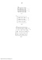
Em outro tipo de modalidade, o bloco de construção básico inclui um tubo cilíndrico ou uma configuração em concha. De acordo com a ilustração pertinente à Figura 2A, um elemento de conversão cilíndrica 110 consiste em um núcleo cilíndrico 112 de material do tipo A envolvido por uma concha ou tubo cilíndrico 114 de material do tipo B. De acordo com a descrição dada pela Figura 2B, é possível novamente de forma opcional se circundar cada concha 114 do material de tipo B com uma concha de isolamento 116 do material de tipo C. Neste tipo de configuração cilíndrica, as mesmas regras dimensionais se aplicam para as diversas espessuras, ou seja, os raios dos núcleos cilíndricos 112 do material de tipo A vem a serem menores ou da ordem de em torno metade do caminho médio livre do elétron no material de tipo A, em torno de Jc(Zi)/2, enquanto que a espessura da concha 114 do material de tipo B se apresenta da ordem do caminho médio livre do elétron na material B, em torno de J[c(Z2).In another type of embodiment, the basic building block includes a cylindrical tube or a shell configuration. According to the illustration pertinent to Figure 2A, a
A vantagem do uso do tubo cilíndrico ou da disposição em concha do elemento conversor 110 é de que uma eficiência mais elevada dá condição a captura dos elétrons emitidos conforme eles vão sendo emitidos com igual probabilidade ao longo de 360° em azimute. De acordo com a descrição anterior dada e pela Figura 3, os elétrons e- são ejetados em uma direção primariamente no plano Pc (contendo uma distribuição angular de decaimento apropriada afastada daquele plano, porém sendo um máximo no mesmo) perpendicular à direção de propagação do fóton v e paralela a polarização (E) dos fótons. Dependendo do ângulo de polarização do fóton, os elétrons ejetados e- podem vir a serem direcionadas em qualquer sentido em torno dos 360° azimutais, sendo que em tal caso a disposição cilíndrica da célula conduz a uma captura mais elevada de elétrons no material de tipo B, e efetivamente a uma eficiência maior de captura de elétrons em comparação com as configurações lineares descritas pela Figuras de 1A a 1F.The advantage of using the cylindrical tube or the shell arrangement of the
Em semelhança com o conversor de geometria linear descrito anteriormente, os blocos de construção cilíndrica 110 são agrupados para dar formação a estruturas agregadas que se conformam as mesmas restrições de tamanho físico do conversor de geometria linear. Como exemplo, tem-se uma disposição particular de empilhamento 11 detalhada na Figura 2C. Alternativamente, de acordo com a descrição dada na Figura 2D, em um outro tipo de disposição de empilhamento 113, o material de isolamento 116 pode preencher o espaço vazio entre os elementos ou células de conversão adjacentes 110. Tal espaço vazio pode servir ainda como um conduto para circulação dos refrigerantes a gás, tal como o Hélio pressurizado. Isto forma um mecanismo efetivo de resfriamento em função da absorção de fótons pelo He vir a ser desprezível em relação as energias fotônicas de interesse. As conexões físicas são novamente similares as configurações de geometria linear e da mesma maneira possibilitam a presença de muitas opções diferenciadas em conexão com as camadas ou conchas 112 e 114 dos blocos de construção 110.Similar to the linear geometry converter described above,
Configurações geométricas alternativas são apresentadas nas Figuras 2E, 2F e 2G. A Figura 2E apresenta uma disposição assentada linearmente em pilha aonde as camadas 112 do material de tipo A são deslocadas de forma a serem posicionadas nas camadas adjacentes 114 do material de tipo B. A Figura 2F apresenta uma pluralidade de núcleos 112 do material de tipo A circundado pelo material de tipo B preenchendo os espaços vazios 114 existentes entre os núcleos 112. Muito embora mostrados sob formato de quadrados, os núcleos 12 podem se apresentar circulares, ovais, ou coisas do gênero. A Figura 2G é semelhante a configuração presente na Figura 2D com a exceção do núcleo 112 e da camada em concha 114 virem a apresentar um formato quadrado. Nesses casos o dimensionamento dos elementos 112, 114 e 116 se conforma dentro de restrições idênticas as descritas nas Figuras de 1A a 1C e das Figuras de 2A a 2D. A dinâmica dos elétrons junto à bordas dos quadrados se apresenta diferente, porém a parte desses efeitos advindos das bordas, outras propriedades físicas são, em geral, semelhantes as situações cilíndricas.Alternative geometric configurations are shown in Figures 2E, 2F and 2G. Figure 2E shows a linearly stacked arrangement where
O bloco de construção básica, em qualquer tipo de geometria, formado em até três tipos de materiais de acordo com a descrição anterior, é adequado para gerar espontaneamente a separação de elétrons do sítio original de átomos doadores, que pode haver sido ionizado por fótons de alta energia. Isto por sua vez dá surgimento a geração de voltagens elétricas entre as camadas e/ou através de um isolante opcional. De acordo com a discussão acima, tal tipo de disposição pode vir a ser conectada eletricamente junto a um circuito para efetuar o trabalho elétrico ou a transmissão de força ao conversor. Como forma de uma variante adicional, deve-se observar que pode-se aplica ainda uma tensão externa (tensão polarizada) entre essas camadas, proporcionando-se com um controle a mais em relação as propriedades elétrica e minimizando o potencial quanto ao arqueamento ao longo de qual-quer uma das camadas.The basic building block, in any type of geometry, formed in up to three types of materials according to the previous description, is suitable for spontaneously generating the separation of electrons from the original site of donor atoms, which may have been ionized by photons of high energy. This in turn gives rise to the generation of electrical voltages between the layers and / or through an optional insulator. According to the discussion above, this type of arrangement can be electrically connected to a circuit to perform electrical work or power transmission to the converter. As a form of an additional variant, it should be noted that an external voltage (polarized voltage) can be applied between these layers, providing additional control over electrical properties and minimizing the potential for bending over of any of the layers.
Com referência as Figuras 4A e 4B, de forma a se vir a minimizar a área de superfície exposta a radiação garantindo-se que o fóton v de alta energia incidente seja capturado pela camada 212 do material de tipo A , não passando tão simplesmente através de uma camada 214 do material de tipo B, as camadas empilhadas 212 e 214 dos materiais de tipo A e B, e a camada opcional 216 do material de isolamento do tipo C, de uma telha ou célula de conversor 200 são inclinadas, preferencialmente, sob um ângulo raso (pequeno) θ na direção de propagação do fóton incidente contendo alta energia v, o qual, por exemplo, pode ser da ordem de em torno 1/100 radianos. A inclinação da telha de conversor 200 assegura também um resfriamento adequado do material de tipo A bombardeado e minimiza a espessura de cada camada individual 212 do material de tipo A (em relação ao caminho médio livre dos elétrons), assim como a espessura efetiva agregada de todas as camadas 212 do material de tipo A no conjunto de conversor integral. A inclinação da telha de conversor 200 a um ângulo raso ocasiona ainda a que os elétrons venham a ser ejetados predominantemente perpendicularmente à superfície do material de tipo A. Isso reduz ainda a quantidade necessária de camadas repetidas por telha 200 por um fato de aproximadamente 1/0, con-forme a distância de transmissão no material de tipo A seja acentuada pelo mesmo fator em relação ao caso em que o ângulo de orientação ψ da superfície de telha 200 seja organizado normal a direção de propagação do fóton incidente de alta energia v. Isto maximiza também o escape de elétrons para a camada adjacente do material de tipo B.Referring to Figures 4A and 4B, in order to minimize the surface area exposed to radiation, ensuring that the incident high energy v photon is captured by
Em uma modalidade alternativa, a telha de conversor 200 descrita nas Figuras 4A e 4B compreendem de uma pluralidade de elementos de conversão cilíndrica 110 (mostrados nas Figuras 2A e 2B) empilhados lado a lado e inclinados a um ângulo raso 0.In an alternative embodiment, the
Com referência a Figura 4B, de forma a absorver efetivamente a maior parte dos fótons de alta energia contendo energia da ordem de em torno 100 keV, a altura H do dispositivo necessita de se estender a ordens de extensões de em torno de 1 centímetro (1 cm) na direção geral de propagação do fóton predominante. Isto ocorre devido ao desejo de se interceptar o fluxo de fótons integral contendo material do tipo A contendo espessura agregada suficiente na direção de propagação de fótons. Uma vez que a espessura de cada camada de material de tipo B venha a ser tipicamente muito maior do que a espessura de cada camada do material de tipo A (« £), a altura total H da pilha completa de blocos de construção projetada na direção do fluxo de fótons necessita de ser muito mais elevada do que o caminho médio livre dos fótons particulares presentes no material de tipo A para garantir-se que os fótons de alta energia encontrem o material de tipo A ao longo de uma distância agregada maior do que os seus caminhos médios livres em tal material. A altura da pilha completa de blocos de construção, portanto, viria a exceder o caminho médio livre dos fótons no material de tipo A por um fator de pelo menos j? / Ji ou, no caso de inclusão da camada isolante, por um fator de pelo menos (J3+ £)/ Ji.With reference to Figure 4B, in order to effectively absorb most of the high energy photons containing energy of the order of around 100 keV, the height H of the device needs to extend to orders of extensions of around 1 centimeter (1 cm) in the general direction of propagation of the predominant photon. This is due to the desire to intercept the integral photon flow containing type A material containing sufficient aggregate thickness in the direction of photon propagation. Since the thickness of each layer of type B material will typically be much greater than the thickness of each layer of type A material ('£), the total height H of the complete stack of building blocks projected in the direction of photon flow needs to be much higher than the average free path of the particular photons present in type A material to ensure that high energy photons encounter type A material over an aggregate distance greater than their free average ways in such material. The height of the complete stack of building blocks, therefore, would exceed the mean free path of photons in type A material by a factor of at least j? / Ji or, in the case of inclusion of the insulating layer, by a factor of at least (J3 + £) / Ji.
Conforme mencionado anteriormente, o posicionamento genérico mostra-se efetivo no resfriamento dos materiais do conversor conforme eles venham a ser aquecidos pela absorção de fóton assim como por um posterior aquecimento pelos elétrons. O resfriamento é facilitado devido a área de superfície total na modalidade presente de acordo com a descrição detalhada na Figura 4A vir a ser ampliada em comparação com uma simples disposição de acomodação das pilhas sob um ângulo de orientação perpendicular a direção do fluxo de fótons incidente por um fator de 1/0. Ainda é possível se escoar refrigerante de gás pressurizado através dos canos construídos na estrutura ou simplesmente conectar-se as pilhas junto aos sugadores térmicos. Um técnico da área irá prontamente identificar que podem existir muitas outras maneiras de se intensificar o resfriamento e que as referentes implementações particulares poderão vir a serem regidas pela aplicação específica.As previously mentioned, the generic positioning is shown to be effective in cooling the converter materials as they are heated by photon absorption as well as by subsequent heating by electrons. Cooling is facilitated because the total surface area in the present mode according to the description detailed in Figure 4A will be expanded in comparison to a simple arrangement of accommodation of the cells under an orientation angle perpendicular to the direction of the photon flow incident by a factor of 1/0. It is still possible to drain pressurized gas refrigerant through the pipes built into the structure or simply connect the batteries together with the thermal suckers. A technician in the field will readily identify that there are many other ways to intensify cooling and that the particular implementations that may be governed by the specific application.
Um conjunto 220 das telhas de conversor 200, de acordo com a descrição dada pela Figura 5, pode ser posicionado ao longo de uma superfície de conformação 230 interceptando e sendo substancialmente perpendicular ao fluxo de fótons 242 emitido a partir de uma dada fonte de fluxo de fótons 240. Esta configuração proporciona com flexibilidade e adaptabilidade junto a um amplo espectro de aplicações que podem requerer (ou virem a se beneficiar) da geração de energia a partir de um fluxo de fótons emitido.A
Outros exemplos das geometrias genéricas de típicas aplicações são descritos nas Figuras 6A, 6B e 6C. A Figura 6A apresenta um sistema de refreamento de plasma 300 que inclui uma câmara cilíndrica 330 contendo uma superfície 334 interceptando e se apresentando substancialmente perpendicular a um fluxo de fóton 342 emitido a partir de uma fonte de fluxo de fótons mostrada como plasma em fusão. O sistema de retenção 300 incorpora ainda um gerador de campo magnético 332 posicionado ao longo da câmara cilíndrica 330 e de uma disposição 332 das telhas de conversão 200 fixada ao longo da superfície 334 da câmara 330. Cada uma das telhas vem a ser orientada sob um ângulo raso junto à direção de propagação dos fótons incidentes de alta energia v do fluxo de fótons 342. A Figura 6B mostra um sistema de refreamento 400 que inclui um contêiner cilíndrico 430 incorporando uma superfície 434 interceptando e se apresentando substancialmente perpendicular ao fluxo de fótons 442 emitido a partir de uma superfície 440 do fluxo de fótons emitido em forma de plasma sob fusão ou como barras gastas de combustível nuclear. O sistema de refreamento 400 compreende ainda de uma disposição 432 ou de telhas de conversor 200 afixadas em torno da superfície 434 do contêiner 430. Cada uma das telhas é orientada sob um ângulo raso na direção de propagação dos fótons incidentes de alta energia v do fluxo de fótons 442. A Figura 6C apresenta um sistema de aceleração de partículas 500 que inclui um tubo cilíndrico 530 apresentando uma superfície 534 interceptando e sendo substancialmente perpendicular a um fluxo de fótons 542 emitidos a partir de uma fonte 540 do fluxo de fótons apresentado como um feixe de partículas aceleradas. O sistema de acelerador 500 compreende ainda um gerador de campo magnético 532 posicionado ao longo do tubo cilíndrico 530 e uma disposição 532 das telhas de conversão 200 afixadas ao longo da superfície 534 do tubo 530. Cada uma das telhas vem a ser orientada sob um ângulo raso na direção de propagação dos fótons incidentes de alta energia v do fluxo de fótons 542.Other examples of generic geometries for typical applications are described in Figures 6A, 6B and 6C. Figure 6A shows a
Em cada caso, os fótons emitidos de alta energia encontram o material de tipo A ao longo de uma distância agregada maior do que os seus caminhos médios livres em tal material A. Isto assegura as suas devidas absorções pelos átomos no interior das camadas do tipo A e em última análise amplificação a conversão da corrente de fótons em corrente de elétrons. Em torno do volume sendo emitido pelo fluxo, o material de tipo A abrange densamente todo o fluxo de fótons de alta energia exposto nas áreas de superfície, enquanto ao mesmo tempo dando condição ao resfriamento e a conexões elétricas.In each case, the photons emitted from high energy encounter the type A material over an aggregate distance greater than their average free paths in such material A. This ensures their proper absorption by the atoms within the type A layers. and ultimately amplifying the conversion of photon current to electron current. Around the volume being emitted by the flow, type A material densely covers the entire flow of high-energy photons exposed in the surface areas, while at the same time providing conditions for cooling and electrical connections.
Deve ser observado que de acordo com as modalidades disponibilizadas por este relatório, que múltiplos elétrons são emitidos a partir de um átomo em particular no material de tipo A em função da absorção dos fótons de alta energia. Isto ocorre devido a um elétron ser expulso de uma órbita eletrónica profunda em particular na concha interna criando um vazio, que deve vir a ser rapidamente preenchido através do processo de Auger, que por sua vez aciona com processos Auger secundários e terciários, ou uma cascata de processos. Além disso, a reemissão secundária de fótons pode acionar processos adicionais nos átomos vizinhos. Por consequência, um fóton pode em princípio fazer acionar a emissão agregada de em torno de 100 elétrons (e as vezes mais). Portanto, esta múltipla ionização proporciona com benefícios diversos. Primeiramente, ela serve para multiplicar a quantidade de elétrons por fóton original incidente por um fator de 100 a 1000, levando a uma amplificação elevada da corrente. Em segundo lugar, ela serve para reduzir as energias dos elétrons de dez ordens de keV a meramente dez ordens de eV. Desse modo, a tensão gerada pode ser gerenciada em relação a questões relacionadas a interrupções. Isto fornece com uma intensificação da conversão da energia dos fótons em eletricidade (suas cargas e corrente), enquanto minimiza também o aquecimento do alvo em vista. De fato, o sistema serve como um eficaz mecanismo de resfriamento por meio da remoção da maior parte da energia de fótons depositada (via energia elétrica) a partir do material vindo a se acomodar próximo a fonte de fótons e prontamente transportando a energia convertida para sítios afastados longa da vizinhança da radiação.It should be noted that according to the modalities provided by this report, that multiple electrons are emitted from a particular atom in type A material as a function of the absorption of high energy photons. This is due to an electron being expelled from a deep electronic orbit in particular in the inner shell creating a void, which must be quickly filled through the Auger process, which in turn triggers with secondary and tertiary Auger processes, or a cascade of processes. In addition, secondary photon re-emission can trigger additional processes in neighboring atoms. Consequently, a photon can in principle trigger the aggregate emission of around 100 electrons (and sometimes more). Therefore, this multiple ionization provides several benefits. First, it serves to multiply the amount of electrons per original incident photon by a factor of 100 to 1000, leading to high current amplification. Second, it serves to reduce the electron energies of ten orders of keV to merely ten orders of eV. In this way, the voltage generated can be managed in relation to issues related to interruptions. This provides an intensification of the conversion of photon energy into electricity (their charges and current), while also minimizing the heating of the target in view. In fact, the system serves as an effective cooling mechanism by removing most of the photon energy deposited (via electrical energy) from the material, settling close to the photon source and promptly transporting the converted energy to sites long away from the radiation neighborhood.
Modalidades de exemplos fornecidas por este relatório, contudo, se destinam meramente como exemplos ilustrativos e não pretendem serem restritivas de nenhuma forma. Além disso, os técnicos da área irão identificar que sistemas semelhantes podem ser igualmente adaptados aos fótons contendo diferentes níveis de energia a partir de modificações apropriadas dos parâmetros.Example modalities provided by this report, however, are intended as illustrative examples only and are not intended to be restrictive in any way. In addition, technicians in the field will identify that similar systems can be equally adapted to photons containing different levels of energy from appropriate modifications of the parameters.
Na descrição fornecida, a invenção foi detalhada tendo como referência suas modalidades. Entretanto, fica evidente que diversas modificações e alterações podem vir a serem efetuadas sem haver o desvio do espírito e escopo mais abrangentes da invenção. Por exemplo, o leitor deve compreender que a ordenação específica e combinação das ações do processos apresentadas nos fluxogramas do processo, descritos por este relatório, tem caráter meramente ilustrativo, a menos que de outra forma assim estabelecido, com a invenção podendo ser praticada através do emprego de ações de processo diferentes ou adicionais, ou através de uma combinação diferenciada ou ordenação diferenciada das ações do processo. Como forma de outro exemplo, cada característica de um tipo de modalidade pode vir a ser misturada e conjugada com outras características apresentadas em outras modalidades. As características e processos conhecidos pelos especialistas da área podem ser incorporados de forma semelhante conforme o desejado. Adicionalmente e obviamente, as características podem ser adicionadas ou subtraídas conforme o desejado. Consequentemente, a invenção não apresenta restrições, exceto em vista do quadro de reivindicações anexo e seus equivalentes.In the description provided, the invention was detailed with reference to its modalities. However, it is evident that several modifications and alterations can be made without deviating from the broader spirit and scope of the invention. For example, the reader must understand that the specific ordering and combination of the process actions presented in the process flowcharts, described by this report, is for illustrative purposes only, unless otherwise established, with the invention being able to be practiced through the use of different or additional process actions, or through a different combination or different ordering of the process actions. As a form of another example, each characteristic of a type of modality may be mixed and conjugated with other characteristics presented in other modalities. The characteristics and processes known to experts in the field can be incorporated in a similar way as desired. Additionally and obviously, the features can be added or subtracted as desired. Consequently, the invention has no restrictions, except in view of the attached claims table and its equivalents.
Claims (19)
Applications Claiming Priority (3)
| Application Number | Priority Date | Filing Date | Title |
|---|---|---|---|
| US29328210P | 2010-01-08 | 2010-01-08 | |
| US61/293,282 | 2010-01-08 | ||
| PCT/US2011/020001 WO2011084903A1 (en) | 2010-01-08 | 2011-01-01 | Conversion of high-energy photons into electricity |
Publications (2)
| Publication Number | Publication Date |
|---|---|
| BR112012016873A2 BR112012016873A2 (en) | 2018-06-05 |
| BR112012016873B1 true BR112012016873B1 (en) | 2020-10-20 |
Family
ID=44305761
Family Applications (1)
| Application Number | Title | Priority Date | Filing Date |
|---|---|---|---|
| BR112012016873-8A BR112012016873B1 (en) | 2010-01-08 | 2011-01-01 | energy converter for converting high energy photon emissions into electrical energy |
Country Status (19)
| Country | Link |
|---|---|
| US (3) | US9324897B2 (en) |
| EP (1) | EP2522033B1 (en) |
| JP (3) | JP6097563B2 (en) |
| KR (1) | KR101962974B1 (en) |
| CN (2) | CN107123692B (en) |
| AR (1) | AR079858A1 (en) |
| AU (2) | AU2010339631B2 (en) |
| BR (1) | BR112012016873B1 (en) |
| CA (1) | CA2786590C (en) |
| EA (1) | EA025124B1 (en) |
| ES (1) | ES2705690T3 (en) |
| IL (2) | IL220819A (en) |
| MX (1) | MX2012007991A (en) |
| NZ (1) | NZ601448A (en) |
| SG (1) | SG182383A1 (en) |
| TW (2) | TWI463681B (en) |
| UA (1) | UA111585C2 (en) |
| WO (1) | WO2011084903A1 (en) |
| ZA (1) | ZA201205568B (en) |
Families Citing this family (26)
| Publication number | Priority date | Publication date | Assignee | Title |
|---|---|---|---|---|
| RU2503159C2 (en) | 2009-02-04 | 2013-12-27 | Дженерал Фьюжен, Инк. | Apparatus for compressing plasma and method of compressing plasma |
| EP2420112B1 (en) | 2009-04-16 | 2017-03-01 | Eric H. Silver | Monochromatic x-ray apparatus |
| EP2460160B8 (en) | 2009-07-29 | 2013-12-04 | General Fusion, Inc. | Systems and methods for plasma compression with recycling of projectiles |
| ES2705690T3 (en) | 2010-01-08 | 2019-03-26 | Tae Tech Inc | Conversion of high energy photons into electricity |
| WO2014032186A1 (en) | 2012-08-29 | 2014-03-06 | General Fusion, Inc. | Apparatus for accelerating and compressing plasma |
| JP2017518011A (en) * | 2014-03-03 | 2017-06-29 | ブリリアント ライト パワー インコーポレーティド | Photovoltaic power generation system and method related to the same |
| WO2015200494A1 (en) | 2014-06-25 | 2015-12-30 | Mayo Foundation For Medical Education And Research | System and method for quantitative muscle ultrasound for diagnosis of neuromuscular disease |
| CA2958399C (en) | 2014-08-19 | 2017-07-04 | General Fusion Inc. | System and method for controlling plasma magnetic field |
| US10269463B2 (en) * | 2015-02-03 | 2019-04-23 | The United States Of America As Represented By The Administrator Of Nasa | Nuclear thermionic avalanche cells with thermoelectric (NTAC-TE) generator in tandem mode |
| US11063198B2 (en) | 2016-04-05 | 2021-07-13 | United States Of America As Represented By The Administrator Of Nasa | Metallic junction thermoelectric generator |
| AU2018269056B2 (en) | 2017-05-19 | 2024-01-25 | Imagine Scientific, Inc. | Monochromatic x-ray imaging systems and methods |
| CN107783170A (en) * | 2017-09-28 | 2018-03-09 | 摩瑞尔电器(昆山)有限公司 | Using the gamma ray detection equipment of composite structure shell |
| US10811144B2 (en) | 2017-11-06 | 2020-10-20 | General Fusion Inc. | System and method for plasma generation and compression |
| US10886452B2 (en) | 2018-01-25 | 2021-01-05 | United States Of America As Represented By The Administrator Of Nasa | Selective and direct deposition technique for streamlined CMOS processing |
| US10818467B2 (en) * | 2018-02-09 | 2020-10-27 | Imagine Scientific, Inc. | Monochromatic x-ray imaging systems and methods |
| KR20210011903A (en) | 2018-02-09 | 2021-02-02 | 이매진 싸이언티픽, 인크. | Monochromatic X-ray imaging system and method |
| US11037687B2 (en) | 2018-03-13 | 2021-06-15 | United States Of America As Represented By The Administrator Of Nasa | Co-60 breeding reactor tandem with thermionic avalanche cell |
| US11004666B2 (en) | 2018-03-15 | 2021-05-11 | United States Of America As Represented By The Administrator Of Nasa | Portable miniaturized thermionic power cell with multiple regenerative layers |
| US10985676B2 (en) | 2018-03-15 | 2021-04-20 | United States Of America As Represented By The Administrator Of Nasa | High performance electric generators boosted by nuclear electron avalanche (NEA) |
| US11257604B2 (en) | 2018-05-30 | 2022-02-22 | United States Of America As Represented By The Administrator Of Nasa | Multi-layered radio-isotope for enhanced photoelectron avalanche process |
| KR102091228B1 (en) * | 2018-06-05 | 2020-03-19 | 서울방사선서비스주식회사 | System and method for managing quality of dosimeter |
| WO2020056281A1 (en) | 2018-09-14 | 2020-03-19 | Imagine Scientific, Inc. | Monochromatic x-ray component systems and methods |
| US11581104B2 (en) | 2019-05-21 | 2023-02-14 | United States Of America As Represented By The Administrator Of Nasa | Multi-layer structure of nuclear thermionic avalanche cells |
| US20220108814A1 (en) * | 2020-10-01 | 2022-04-07 | Robert W Moses | Surface Flashover and Material Texturing for Multiplying and Collecting Electrons for Nuclear Thermal Avalanche Cells and Nuclear Battery Devices |
| EP4302313A1 (en) * | 2021-03-01 | 2024-01-10 | TAE Technologies, Inc. | Carbon negative reactors |
| US20220302331A1 (en) * | 2021-03-22 | 2022-09-22 | Matthew Ryan Hankla | Methods, systems, and apparatuses for producing, generating and utilizing power and energy |
Family Cites Families (32)
| Publication number | Priority date | Publication date | Assignee | Title |
|---|---|---|---|---|
| US739987A (en) * | 1898-11-11 | 1903-09-29 | American Tobacco Co | Delivery mechanism for cigarette-machines. |
| US2847585A (en) * | 1952-10-31 | 1958-08-12 | Rca Corp | Radiation responsive voltage sources |
| GB761404A (en) * | 1953-06-30 | 1956-11-14 | Rca Corp | Improved methods of and means for converting the energy of nuclear radiations into useful electrical energy |
| US3284241A (en) * | 1962-02-13 | 1966-11-08 | Philco Corp | Photo-emissive device including emitter and insulator of less than mean free path dimensions |
| BE716262A (en) | 1967-07-25 | 1968-11-04 | ||
| US3591860A (en) * | 1968-07-22 | 1971-07-06 | Henry T Sampson | Gamma-electric cell |
| US3821556A (en) | 1972-02-15 | 1974-06-28 | Nasa | Three mirror glancing incidence system for x ray telescope |
| CH539928A (en) * | 1972-05-26 | 1973-07-31 | Biviator Sa | Nuclear battery |
| US4178524A (en) * | 1976-09-01 | 1979-12-11 | Ritter James C | Radioisotope photoelectric generator |
| JPH065291B2 (en) * | 1986-07-02 | 1994-01-19 | 株式会社日立製作所 | Radiation detector |
| JP2687122B2 (en) * | 1987-01-26 | 1997-12-08 | 株式会社ジャパンエナジー | Multilayer CdTe radiation detection element |
| US4873555A (en) * | 1987-06-08 | 1989-10-10 | University Of Pittsburgh Of The Commonwealth System Of Higher Education | Intraband quantum well photodetector and associated method |
| US5111099A (en) * | 1990-03-02 | 1992-05-05 | Genesis Energy Systems, Inc. | Apparatus and method for converting radioactive energy into electrical energy |
| JP3126158B2 (en) | 1991-04-10 | 2001-01-22 | 日本放送協会 | Thin film cold cathode |
| GB9415584D0 (en) * | 1994-08-02 | 1994-09-21 | Imperial College | Photo detector |
| WO1999065050A1 (en) * | 1998-06-11 | 1999-12-16 | Petr Viscor | Planar electron emitter (pee) |
| FR2792418B1 (en) * | 1999-04-15 | 2001-06-01 | Commissariat Energie Atomique | TWO-DIMENSIONAL DETECTOR OF IONIZING RADIATION AND METHOD OF MANUFACTURING THE SAME |
| SE514471C2 (en) * | 1999-04-30 | 2001-02-26 | Xcounter Ab | X-ray detector unit with fixed type converter |
| JP3938908B2 (en) * | 2000-10-20 | 2007-06-27 | 仗祐 中田 | Light-emitting or light-receiving semiconductor device and manufacturing method thereof |
| US6774300B2 (en) * | 2001-04-27 | 2004-08-10 | Adrena, Inc. | Apparatus and method for photovoltaic energy production based on internal charge emission in a solid-state heterostructure |
| WO2002103392A1 (en) | 2001-06-18 | 2002-12-27 | Wisconsin Alumni Research Foundation | Radiation detector with converters |
| US7485799B2 (en) * | 2002-05-07 | 2009-02-03 | John Michael Guerra | Stress-induced bandgap-shifted semiconductor photoelectrolytic/photocatalytic/photovoltaic surface and method for making same |
| JP3837528B2 (en) | 2002-12-13 | 2006-10-25 | 国立大学法人名古屋大学 | Power generation method and battery |
| JP3861154B2 (en) * | 2003-09-04 | 2006-12-20 | 国立大学法人名古屋大学 | Power generation method and battery |
| CN101042945A (en) * | 2006-07-20 | 2007-09-26 | 永州市健民射线防护设备有限公司 | Environment-friendly type radiation protection composite board |
| TW200812096A (en) * | 2006-08-25 | 2008-03-01 | Kinik Co | Amorphous diamond energy converter |
| CN100501924C (en) * | 2006-12-19 | 2009-06-17 | 华东师范大学 | A making method for the radiant energy conversion chip |
| CN101627479B (en) | 2007-01-30 | 2011-06-15 | 索拉斯特公司 | Photovoltaic cell and method of making thereof |
| JP5419099B2 (en) | 2007-05-15 | 2014-02-19 | エアロフレックス コロラド スプリングス インコーポレイテッド | Direct conversion radiation detector and method for converting ionizing radiation directly into current |
| US20090065056A1 (en) * | 2007-09-12 | 2009-03-12 | Sub-One Technology | Hybrid photovoltaically active layer and method for forming such a layer |
| FI121828B (en) * | 2007-12-04 | 2011-04-29 | Finphys Oy | Radiation detector, method of producing a radiation detector and use of the detector for measuring radiation |
| ES2705690T3 (en) | 2010-01-08 | 2019-03-26 | Tae Tech Inc | Conversion of high energy photons into electricity |
-
2011
- 2011-01-01 ES ES11732017T patent/ES2705690T3/en active Active
- 2011-01-01 US US13/521,220 patent/US9324897B2/en active Active
- 2011-01-01 JP JP2012548054A patent/JP6097563B2/en active Active
- 2011-01-01 WO PCT/US2011/020001 patent/WO2011084903A1/en active Application Filing
- 2011-01-01 EA EA201290620A patent/EA025124B1/en unknown
- 2011-01-01 UA UAA201209620A patent/UA111585C2/en unknown
- 2011-01-01 CN CN201610882742.0A patent/CN107123692B/en active Active
- 2011-01-01 SG SG2012049854A patent/SG182383A1/en unknown
- 2011-01-01 BR BR112012016873-8A patent/BR112012016873B1/en active IP Right Grant
- 2011-01-01 NZ NZ601448A patent/NZ601448A/en unknown
- 2011-01-01 EP EP11732017.6A patent/EP2522033B1/en active Active
- 2011-01-01 CA CA2786590A patent/CA2786590C/en active Active
- 2011-01-01 CN CN201180012910.6A patent/CN102859706B/en active Active
- 2011-01-01 MX MX2012007991A patent/MX2012007991A/en active IP Right Grant
- 2011-01-01 AU AU2010339631A patent/AU2010339631B2/en active Active
- 2011-01-01 KR KR1020127020707A patent/KR101962974B1/en active IP Right Grant
- 2011-01-07 AR ARP110100050 patent/AR079858A1/en active IP Right Grant
- 2011-01-07 TW TW100100596A patent/TWI463681B/en active
- 2011-01-07 TW TW103137578A patent/TWI552362B/en active
-
2012
- 2012-07-08 IL IL220819A patent/IL220819A/en active IP Right Grant
- 2012-07-24 ZA ZA2012/05568A patent/ZA201205568B/en unknown
-
2016
- 2016-02-19 AU AU2016201030A patent/AU2016201030B2/en active Active
- 2016-03-31 US US15/087,283 patent/US9570644B2/en active Active
- 2016-05-24 JP JP2016103082A patent/JP6327722B2/en active Active
- 2016-12-28 US US15/392,769 patent/US9893226B2/en active Active
-
2017
- 2017-01-11 IL IL250054A patent/IL250054B/en active IP Right Grant
- 2017-10-23 JP JP2017204520A patent/JP2018028552A/en not_active Withdrawn
Also Published As
Similar Documents
| Publication | Publication Date | Title |
|---|---|---|
| BR112012016873B1 (en) | energy converter for converting high energy photon emissions into electrical energy | |
| US6949865B2 (en) | Apparatus and method for generating electrical current from the nuclear decay process of a radioactive material | |
| US6774531B1 (en) | Apparatus and method for generating electrical current from the nuclear decay process of a radioactive material | |
| US20130154438A1 (en) | Power-Scalable Betavoltaic Battery | |
| BR122020018713B1 (en) | Negative ion based beam injector | |
| US9824785B1 (en) | Energy conversion with stacks of nanocapacitors | |
| JP2006338945A (en) | Neutron generation tube | |
| Polikarpov et al. | Study of the properties of silicon-based semiconductor converters for betavoltaic cells | |
| Shen et al. | Preliminary design of a synchrotron radiation exit port crotch for Cornell B-factory | |
| SU1737559A1 (en) | Secondary emission type radioisotope current source | |
| Song et al. | X‐ray Beamlines On A Superconducting Wavelength Shifter | |
| Kuckuck et al. | High-intensity, subkolovolt x-ray calibration facility using a Cockroft--Walton proton accelerator | |
| Micelli | 3D sensors for the Insertable B-Layer of the ATLAS experiment at the CERN LHC | |
| He et al. | Thermal Analysis of the Al Window for a New CESR-C Luminosity Monitor | |
| Ullaland | CERN Summer Student Lectures Detectors. A write-up. | |
| Seidel et al. | Inverse Diode for Combination of Multiple Modules and Fusion Driver-Target Standoff. |
Legal Events
| Date | Code | Title | Description |
|---|---|---|---|
| B06F | Objections, documents and/or translations needed after an examination request according [chapter 6.6 patent gazette] | ||
| B06U | Preliminary requirement: requests with searches performed by other patent offices: procedure suspended [chapter 6.21 patent gazette] | ||
| B07A | Application suspended after technical examination (opinion) [chapter 7.1 patent gazette] | ||
| B25D | Requested change of name of applicant approved |
Owner name: TAE TECHNOLOGIES, INC. (US) |
|
| B25B | Requested transfer of rights rejected |
Owner name: TAE TECHNOLOGIES, INC. (US) Free format text: INDEFERIDO O PEDIDO DE TRANSFERENCIA CONTIDO NA PETICAO 870200017020 DE 05/02/2020, EM VIRTUDE DO PEDIDO JA ESTAR EM NOME DO INTERESSADO. |
|
| B09A | Decision: intention to grant [chapter 9.1 patent gazette] | ||
| B16A | Patent or certificate of addition of invention granted [chapter 16.1 patent gazette] |
Free format text: PRAZO DE VALIDADE: 20 (VINTE) ANOS CONTADOS A PARTIR DE 01/01/2011, OBSERVADAS AS CONDICOES LEGAIS. |