BR112012008347B1 - method of measuring a position and / or shape for a multi-core fiber, apparatus for performing position and / or shape measurements of a multi-core fiber and non-transitory storage medium - Google Patents
method of measuring a position and / or shape for a multi-core fiber, apparatus for performing position and / or shape measurements of a multi-core fiber and non-transitory storage medium Download PDFInfo
- Publication number
- BR112012008347B1 BR112012008347B1 BR112012008347-3A BR112012008347A BR112012008347B1 BR 112012008347 B1 BR112012008347 B1 BR 112012008347B1 BR 112012008347 A BR112012008347 A BR 112012008347A BR 112012008347 B1 BR112012008347 B1 BR 112012008347B1
- Authority
- BR
- Brazil
- Prior art keywords
- fiber
- core
- core fiber
- cores
- optical length
- Prior art date
Links
- 239000000835 fiber Substances 0.000 title claims abstract description 334
- 238000005259 measurement Methods 0.000 title claims abstract description 85
- 238000000034 method Methods 0.000 title claims abstract description 27
- 238000003860 storage Methods 0.000 title claims abstract description 5
- 230000008859 change Effects 0.000 claims abstract description 107
- 230000003287 optical effect Effects 0.000 claims abstract description 83
- 238000000691 measurement method Methods 0.000 claims abstract description 3
- 230000004044 response Effects 0.000 claims description 47
- 230000010287 polarization Effects 0.000 claims description 46
- 230000010355 oscillation Effects 0.000 claims description 16
- 238000005452 bending Methods 0.000 claims description 13
- 230000002093 peripheral effect Effects 0.000 claims description 7
- 238000009825 accumulation Methods 0.000 claims description 4
- 238000012544 monitoring process Methods 0.000 claims description 3
- 230000008447 perception Effects 0.000 abstract description 50
- 238000012937 correction Methods 0.000 description 27
- 230000006870 function Effects 0.000 description 19
- 239000013307 optical fiber Substances 0.000 description 15
- 239000013598 vector Substances 0.000 description 14
- 238000004364 calculation method Methods 0.000 description 12
- 238000004519 manufacturing process Methods 0.000 description 7
- 238000012360 testing method Methods 0.000 description 7
- 230000000694 effects Effects 0.000 description 6
- 239000011521 glass Substances 0.000 description 6
- 239000011159 matrix material Substances 0.000 description 6
- 238000002168 optical frequency-domain reflectometry Methods 0.000 description 6
- 238000013459 approach Methods 0.000 description 5
- 230000006835 compression Effects 0.000 description 5
- 238000007906 compression Methods 0.000 description 5
- 230000000737 periodic effect Effects 0.000 description 5
- 230000010363 phase shift Effects 0.000 description 5
- 230000008569 process Effects 0.000 description 5
- 238000009795 derivation Methods 0.000 description 4
- 238000010586 diagram Methods 0.000 description 4
- 238000005516 engineering process Methods 0.000 description 4
- 239000000463 material Substances 0.000 description 4
- 230000035945 sensitivity Effects 0.000 description 4
- 238000000926 separation method Methods 0.000 description 4
- 230000001934 delay Effects 0.000 description 3
- 238000001228 spectrum Methods 0.000 description 3
- 230000001186 cumulative effect Effects 0.000 description 2
- 239000007789 gas Substances 0.000 description 2
- 230000014509 gene expression Effects 0.000 description 2
- LELOWRISYMNNSU-UHFFFAOYSA-N hydrogen cyanide Chemical compound N#C LELOWRISYMNNSU-UHFFFAOYSA-N 0.000 description 2
- 230000002452 interceptive effect Effects 0.000 description 2
- 238000012545 processing Methods 0.000 description 2
- 239000007787 solid Substances 0.000 description 2
- 230000002123 temporal effect Effects 0.000 description 2
- 230000007704 transition Effects 0.000 description 2
- 230000004913 activation Effects 0.000 description 1
- 230000009286 beneficial effect Effects 0.000 description 1
- 238000004422 calculation algorithm Methods 0.000 description 1
- 230000015556 catabolic process Effects 0.000 description 1
- 238000006243 chemical reaction Methods 0.000 description 1
- 238000010276 construction Methods 0.000 description 1
- 230000007423 decrease Effects 0.000 description 1
- 230000007547 defect Effects 0.000 description 1
- 230000007812 deficiency Effects 0.000 description 1
- 230000002950 deficient Effects 0.000 description 1
- 238000006731 degradation reaction Methods 0.000 description 1
- 230000003111 delayed effect Effects 0.000 description 1
- 238000006073 displacement reaction Methods 0.000 description 1
- 238000009826 distribution Methods 0.000 description 1
- 239000003814 drug Substances 0.000 description 1
- 238000000605 extraction Methods 0.000 description 1
- 238000001914 filtration Methods 0.000 description 1
- 230000006872 improvement Effects 0.000 description 1
- 230000010354 integration Effects 0.000 description 1
- 238000005304 joining Methods 0.000 description 1
- 238000012423 maintenance Methods 0.000 description 1
- 230000001151 other effect Effects 0.000 description 1
- 230000002250 progressing effect Effects 0.000 description 1
- 239000000523 sample Substances 0.000 description 1
- 238000013519 translation Methods 0.000 description 1
- 230000014616 translation Effects 0.000 description 1
Images


Classifications
-
- G—PHYSICS
- G01—MEASURING; TESTING
- G01B—MEASURING LENGTH, THICKNESS OR SIMILAR LINEAR DIMENSIONS; MEASURING ANGLES; MEASURING AREAS; MEASURING IRREGULARITIES OF SURFACES OR CONTOURS
- G01B11/00—Measuring arrangements characterised by the use of optical techniques
- G01B11/24—Measuring arrangements characterised by the use of optical techniques for measuring contours or curvatures
-
- G—PHYSICS
- G01—MEASURING; TESTING
- G01B—MEASURING LENGTH, THICKNESS OR SIMILAR LINEAR DIMENSIONS; MEASURING ANGLES; MEASURING AREAS; MEASURING IRREGULARITIES OF SURFACES OR CONTOURS
- G01B11/00—Measuring arrangements characterised by the use of optical techniques
- G01B11/16—Measuring arrangements characterised by the use of optical techniques for measuring the deformation in a solid, e.g. optical strain gauge
- G01B11/168—Measuring arrangements characterised by the use of optical techniques for measuring the deformation in a solid, e.g. optical strain gauge by means of polarisation
-
- G—PHYSICS
- G01—MEASURING; TESTING
- G01B—MEASURING LENGTH, THICKNESS OR SIMILAR LINEAR DIMENSIONS; MEASURING ANGLES; MEASURING AREAS; MEASURING IRREGULARITIES OF SURFACES OR CONTOURS
- G01B11/00—Measuring arrangements characterised by the use of optical techniques
- G01B11/16—Measuring arrangements characterised by the use of optical techniques for measuring the deformation in a solid, e.g. optical strain gauge
- G01B11/18—Measuring arrangements characterised by the use of optical techniques for measuring the deformation in a solid, e.g. optical strain gauge using photoelastic elements
-
- G—PHYSICS
- G01—MEASURING; TESTING
- G01L—MEASURING FORCE, STRESS, TORQUE, WORK, MECHANICAL POWER, MECHANICAL EFFICIENCY, OR FLUID PRESSURE
- G01L1/00—Measuring force or stress, in general
- G01L1/24—Measuring force or stress, in general by measuring variations of optical properties of material when it is stressed, e.g. by photoelastic stress analysis using infrared, visible light, ultraviolet
- G01L1/242—Measuring force or stress, in general by measuring variations of optical properties of material when it is stressed, e.g. by photoelastic stress analysis using infrared, visible light, ultraviolet the material being an optical fibre
-
- G—PHYSICS
- G01—MEASURING; TESTING
- G01M—TESTING STATIC OR DYNAMIC BALANCE OF MACHINES OR STRUCTURES; TESTING OF STRUCTURES OR APPARATUS, NOT OTHERWISE PROVIDED FOR
- G01M11/00—Testing of optical apparatus; Testing structures by optical methods not otherwise provided for
- G01M11/02—Testing optical properties
- G01M11/0242—Testing optical properties by measuring geometrical properties or aberrations
- G01M11/025—Testing optical properties by measuring geometrical properties or aberrations by determining the shape of the object to be tested
-
- G—PHYSICS
- G01—MEASURING; TESTING
- G01M—TESTING STATIC OR DYNAMIC BALANCE OF MACHINES OR STRUCTURES; TESTING OF STRUCTURES OR APPARATUS, NOT OTHERWISE PROVIDED FOR
- G01M11/00—Testing of optical apparatus; Testing structures by optical methods not otherwise provided for
- G01M11/30—Testing of optical devices, constituted by fibre optics or optical waveguides
- G01M11/31—Testing of optical devices, constituted by fibre optics or optical waveguides with a light emitter and a light receiver being disposed at the same side of a fibre or waveguide end-face, e.g. reflectometers
- G01M11/3172—Reflectometers detecting the back-scattered light in the frequency-domain, e.g. OFDR, FMCW, heterodyne detection
-
- G—PHYSICS
- G01—MEASURING; TESTING
- G01M—TESTING STATIC OR DYNAMIC BALANCE OF MACHINES OR STRUCTURES; TESTING OF STRUCTURES OR APPARATUS, NOT OTHERWISE PROVIDED FOR
- G01M11/00—Testing of optical apparatus; Testing structures by optical methods not otherwise provided for
- G01M11/30—Testing of optical devices, constituted by fibre optics or optical waveguides
- G01M11/31—Testing of optical devices, constituted by fibre optics or optical waveguides with a light emitter and a light receiver being disposed at the same side of a fibre or waveguide end-face, e.g. reflectometers
- G01M11/3181—Reflectometers dealing with polarisation
-
- G—PHYSICS
- G01—MEASURING; TESTING
- G01M—TESTING STATIC OR DYNAMIC BALANCE OF MACHINES OR STRUCTURES; TESTING OF STRUCTURES OR APPARATUS, NOT OTHERWISE PROVIDED FOR
- G01M11/00—Testing of optical apparatus; Testing structures by optical methods not otherwise provided for
- G01M11/30—Testing of optical devices, constituted by fibre optics or optical waveguides
- G01M11/33—Testing of optical devices, constituted by fibre optics or optical waveguides with a light emitter being disposed at one fibre or waveguide end-face, and a light receiver at the other end-face
- G01M11/331—Testing of optical devices, constituted by fibre optics or optical waveguides with a light emitter being disposed at one fibre or waveguide end-face, and a light receiver at the other end-face by using interferometer
-
- G—PHYSICS
- G01—MEASURING; TESTING
- G01L—MEASURING FORCE, STRESS, TORQUE, WORK, MECHANICAL POWER, MECHANICAL EFFICIENCY, OR FLUID PRESSURE
- G01L1/00—Measuring force or stress, in general
- G01L1/24—Measuring force or stress, in general by measuring variations of optical properties of material when it is stressed, e.g. by photoelastic stress analysis using infrared, visible light, ultraviolet
- G01L1/242—Measuring force or stress, in general by measuring variations of optical properties of material when it is stressed, e.g. by photoelastic stress analysis using infrared, visible light, ultraviolet the material being an optical fibre
- G01L1/246—Measuring force or stress, in general by measuring variations of optical properties of material when it is stressed, e.g. by photoelastic stress analysis using infrared, visible light, ultraviolet the material being an optical fibre using integrated gratings, e.g. Bragg gratings
-
- G—PHYSICS
- G02—OPTICS
- G02B—OPTICAL ELEMENTS, SYSTEMS OR APPARATUS
- G02B6/00—Light guides; Structural details of arrangements comprising light guides and other optical elements, e.g. couplings
- G02B6/02—Optical fibres with cladding with or without a coating
- G02B6/02042—Multicore optical fibres
Abstract
MÉTODO DE MEDIÇÃO PARA UMA FIBRA DE MÚLTIPLOS NÚCLEOS, APARELHO PARA A REALIZAÇÃO DE MEDIÇÕES DE UMA FIBRA DE MÚLTIPLOS NÚCLEOS E MEIO DE ARMAZENAMENTO NÃO TRANSITÓRIO. A presente invenção refere-se a um método e aparelho para a medição precisa que são descritos para a percepção de formato com uma fibra de múltiplos núcleos. Uma mudança no comprimento ótico é detectada em alguns dos núcleos na fibra de múltiplos núcleos até um ponto na fibra de múltiplos núcleos. Uma localização e/ou direção são determinadas no ponto na fibra de múltiplos núcleos com base nas mudanças detectadas no comprimento ótico. A precisão da determinação é superior a 0,5% do comprimento ótico da fibra de múltiplos núcleos até o ponto na fibra de múltiplos núcleos. Em uma modalidade ilustrativa preferida, a determinação inclui a determinação de um formato de pelo menos uma parte da fibra de múltiplos núcleos com base nas mudanças detectadas no comprimento ótico.MEASUREMENT METHOD FOR A MULTIPLE NUCLEUS FIBER, APPLIANCE FOR MEASURING A MULTIPLE NUCLEUS FIBER AND NON-TRANSITIONAL STORAGE MEDIA. The present invention relates to a method and apparatus for accurate measurement which are described for the perception of shape with a multi-core fiber. A change in optical length is detected in some of the cores in the multi-core fiber up to a point in the multi-core fiber. A location and / or direction is determined at the point in the multi-core fiber based on the detected changes in optical length. The accuracy of the determination is greater than 0.5% of the optical length of the multi-core fiber to the point in the multi-core fiber. In a preferred illustrative embodiment, the determination includes determining a shape of at least a portion of the multi-core fiber based on the detected changes in optical length.
Description
[001] O campo técnico refere-se a medições óticas, e mais particularmente, à posição ótica e/ou percepção de formato. Esta invenção trata de um método e aparelho para realizar tais medições para uma fibra de múltiplos núcleos, e de um associado meio de armazenamento não transitório.[001] The technical field refers to optical measurements, and more particularly, to the optical position and / or format perception. This invention deals with a method and apparatus for making such measurements for a multi-core fiber, and an associated non-transitory storage medium.
[002] A medição de formato é um termo geral que inclui a percepção da posição de estrutura no espaço tridimensional. Essa medição coincide com o que o olho humano percebe como a posição de um objeto.[002] Format measurement is a general term that includes the perception of the position of structure in three-dimensional space. This measurement coincides with what the human eye perceives as the position of an object.
[003] Visto que os olhos realizam continuamente essa tarefa, pode-se assumir que a medição seja simples. Se se considerar um comprimento de corda, pode-se medir fisicamente a posição em cada centímetro ao longo da corda para se estimar o formato. Mas essa tarefa é entediante e é cada vez mais difícil com formatos mais complexos.[003] Since the eyes continuously perform this task, it can be assumed that the measurement is simple. If you consider a rope length, you can physically measure the position at each centimeter along the rope to estimate the shape. But this task is tedious and is increasingly difficult with more complex formats.
[004] Outra consideração é como se realizar a medição se a corda não for fisicamente alcançada ou vista.[004] Another consideration is how to perform the measurement if the rope is not physically reached or seen.
[005] Se a corda for contida dentro de uma caixa vedada, sua posição não pode ser determinada por técnicas de medição convencionais. A corda, nesse exemplo, pode ser substituída por uma fibra ótica.[005] If the string is contained within a sealed box, its position cannot be determined by conventional measurement techniques. The rope, in this example, can be replaced by an optical fiber.
[006] A percepção do formato de um cilindro deformado longo e fino, tal como uma fibra ótica, é útil em muitas aplicações variando, por exemplo, da fabricação e construção até medicina e aplicações aeroespaciais. Na maior parte dessas aplicações, o sistema de percepção de formato deve ser capaz de determinar com precisão a posição da fibra, por exemplo, dentro de menos de um por cento de seu comprimento, e, em muitos casos, menos de um décimo de um po rcento de seu comprimento. Existe um número de abordagens para o problema de medição de formato, mas nenhuma soluciona adequadamente as exigências da maior parte das aplicações visto que são muito lentas, não abordam as precisões necessárias, não funcionam na presença de dobras apertadas, ou falham em compensar adequadamente a torção da fibra. Em muitas aplicações, a presença de forças toroidais que torcem a fibra mina a precisão, e dessa forma, a utilidade dessas abordagens.[006] Perception of the shape of a long, thin, deformed cylinder, such as an optical fiber, is useful in many applications ranging, for example, from manufacturing and construction to medicine and aerospace applications. In most of these applications, the shape perception system must be able to accurately determine the position of the fiber, for example, within less than one percent of its length, and in many cases, less than a tenth of a per cent of its length. There are a number of approaches to the shape measurement problem, but none adequately address the requirements of most applications since they are very slow, do not address the necessary precision, do not work in the presence of tight folds, or fail to adequately compensate for fiber twist. In many applications, the presence of toroidal forces that twist the fiber undermines precision, and thus, the usefulness of these approaches.
[007] Abordagens convencionais para medir o formato de uma fibra utilizam tensão como o sinal de medição fundamental. A tensão é uma razão da mudança no comprimento de um segmento de fibra pós- tensão X o comprimento original desse segmento (pré-tensão). À medida que um objeto como uma fibra é dobrado, o material no exterior da dobra é alongado, enquanto que o material no interior da dobra é comprimido. Conhecendo-se essas mudanças na tensão local e conhecendo-se a posição original do objeto, uma aproximação da nova posição da fibra pode ser realizada.[007] Conventional approaches to measuring the shape of a fiber use voltage as the fundamental measurement signal. The tension is a reason for the change in the length of a post-tension fiber segment X the original length of that segment (pre-tension). As an object such as a fiber is folded, the material on the outside of the fold is stretched, while the material on the inside of the fold is compressed. Knowing these changes in local tension and knowing the original position of the object, an approximation of the new position of the fiber can be performed.
[008] A fim de se perceber efetivamente a posição com alta precisão, vários fatores-chave devem ser solucionados. Primeiro, para uma abordagem baseada em tensão, as medições de tensão são preferivelmente precisas em dezenas de níveis de nanotensões (10 partes por bilhão). Mas as medições de tensão de alta precisão não são prontamente obteníveis pelas medições de tensão resistivas e óticas convencionais. Portanto, uma nova técnica para se medir a tensão com precisão extremamente alta deve ser vislumbrada e não é baseada em tensão no sentido convencional.[008] In order to effectively perceive the position with high precision, several key factors must be resolved. First, for a voltage-based approach, voltage measurements are preferably accurate at dozens of nanotension levels (10 parts per billion). But high precision voltage measurements are not readily obtainable by conventional resistive and optical voltage measurements. Therefore, a new technique for measuring tension with extremely high precision must be envisaged and is not based on tension in the conventional sense.
[009] Em segundo lugar, a presença da torção na fibra ótica deve ser medida a um alto grau de precisão e compensada na computação do formato. Pela criação de uma fibra de múltiplos núcleos que é espiralada e possui um núcleo central, a torção de uma fibra pode ser percebida. Mas o problema é como se obter uma precisão de posição rotativa menor do que 1 grau. Para um sensor de rotação de alta precisão, a posição dos sensores de tensão ao longo do comprimento da fibra deve ser conhecida também com um alto grau de precisão. Portanto, alguma forma de medir a taxa de rotação dos núcleos externos na fibra espiralada é desejável, que pode então ser utilizada para corrigir o cálculo da posição da fibra.[009] Secondly, the presence of the twist in the optical fiber must be measured to a high degree of precision and compensated for in the computation of the format. By creating a multi-core fiber that is coiled and has a central core, the twist of a fiber can be perceived. But the problem is how to obtain a rotational position accuracy less than 1 degree. For a high precision rotation sensor, the position of the tension sensors along the fiber length must also be known with a high degree of accuracy. Therefore, some way of measuring the rotation rate of the outer cores in the coiled fiber is desirable, which can then be used to correct the calculation of the fiber position.
[0010] Em terceiro lugar, a fibra com múltiplos núcleos que é espiralada em uma taxa suficiente e com grade de Bragg (um medido de tensão ótico convencional) é difícil e cara de se fabricar. É, portanto, desejável se fornecer um método de obtenção de resoluções de nanotensão sem grade de Bragg.[0010] Thirdly, the multi-core fiber that is coiled at a sufficient rate and with a Bragg grid (a conventional optical voltage measurement) is difficult and expensive to manufacture. It is therefore desirable to provide a method for obtaining nanotension resolutions without a Bragg grid.
[0011] Em quarto lugar, a fibra de múltiplos núcleos não mantém tipicamente a polarização e, assim, os efeitos da polarização são preferivelmente considerados.[0011] Fourth, the multi-core fiber does not typically maintain polarization and thus the effects of polarization are preferably considered.
[0012] A tecnologia descrita abaixo explica como se utilizar as propriedades intrínsecas da fibra ótica para permitir um cálculo de formato muito preciso em vista dos fatores e considerações acima. Essencialmente, a posição de fibra é determinada pela interpretação dos reflexos posteriores da luz de laser espalhada a partir das moléculas de vidro dentro da fibra. Essa medição pode ser realizada de forma rápida, com uma alta resolução e com um alto grau de precisão.[0012] The technology described below explains how to use the intrinsic properties of the optical fiber to allow a very precise shape calculation in view of the factors and considerations above. Essentially, the position of the fiber is determined by the interpretation of the posterior reflections of the laser light scattered from the glass molecules within the fiber. This measurement can be performed quickly, with a high resolution and with a high degree of accuracy.
[0013] Um método de medição muito preciso e aparelho são descritos para medir a posição e/ou a direção de uma fibra de múltiplos núcleos. Uma mudança no comprimento ótico é detectada em um dos núcleos na fibra de múltiplos núcleos até a ponta na fibra de múltiplos núcleos. Uma localização e/ou uma direção apontada são determinadas na ponta da fibra de múltiplos núcleos com base nas mudanças detectadas no comprimento obtido. A direção corresponde a m ângulo de dobra da fibra de múltiplos núcleos na posição ao longo da fibra de múltiplos núcleos determinada com base nos sinais de tensão ortonormais. A precisão da determinação é melhor do que 0,5% do comprimento ótico da fibra de múltiplos núcleos até a ponta da fibra de múltiplos núcleos. Em uma modalidade ilustrativa preferida, a determinação inclui a determinação de um formato de pelo menos uma parte da fibra de múltiplos núcleos com base nas mudanças detectadas no comprimento ótico.[0013] A very accurate measuring method and apparatus are described to measure the position and / or direction of a multi-core fiber. A change in optical length is detected in one of the cores in the multi-core fiber to the tip in the multi-core fiber. A location and / or a pointed direction are determined at the tip of the multi-core fiber based on the detected changes in the obtained length. The direction corresponds to a bending angle of the multi-core fiber at the position along the multi-core fiber determined based on the orthonormal stress signals. The accuracy of the determination is better than 0.5% of the optical length of the multi-core fiber to the tip of the multi-core fiber. In a preferred illustrative embodiment, the determination includes determining a shape of at least a portion of the multi-core fiber based on the detected changes in optical length.
[0014] A determinação pode incluir o cálculo de um ângulo de dobra da fibra de múltiplos núcleos em qualquer posição ao longo da fibra de múltiplos núcleos com base nas mudanças detectadas no comprimento até a posição. Depois disso, o formato da fibra de múltiplos núcleos pode ser determinado com base no ângulo de dobra calculado. O ângulo de dobra pode ser calculado em duas ou três dimensões.[0014] The determination may include calculating a bend angle of the multi-core fiber at any position along the multi-core fiber based on the detected changes in length to position. Thereafter, the shape of the multi-core fiber can be determined based on the calculated bend angle. The bend angle can be calculated in two or three dimensions.
[0015] A detecção da mudança no comprimento ótico inclui preferivelmente a detecção de uma mudança incremental no comprimento ótico em um dos núcleos na fibra de múltiplos núcleos para cada um dos comprimentos de segmento múltiplos até uma ponta na fibra de múltiplos núcleos. A mudança detectada geral no comprimento ótico é então baseada em uma combinação de mudanças incrementadas. A mudança no comprimento ótico é determinada pelo cálculo de uma mudança de fase ótica em cada comprimento de segmento ao longo da fibra de múltiplos núcleos e o desenrolamento da mudança de fase ótica para se determinar o comprimento ótico.[0015] Detecting the change in optical length preferably includes detecting an incremental change in optical length in one of the cores in the multi-core fiber for each of the multiple segment lengths up to a tip in the multi-core fiber. The overall detected change in optical length is then based on a combination of incremental changes. The change in optical length is determined by calculating an optical phase change at each segment length along the multi-core fiber and the unfolding of the optical phase change to determine the optical length.
[0016] Mais especificamente, em uma modalidade ilustrativa não limitadora, uma resposta de fase de um sinal de luz refletido em pelo menos dois dos múltiplos núcleos a partir de comprimentos de segmento múltiplos pode ser detectada. A tensão na fibra nos comprimentos do segmento causa uma mudança na fase do sinal de luz refletido dos comprimentos dos segmento nos dois núcleos. A resposta de fase é preferivelmente e continuamente monitorada ao longo do comprimento ótico da fibra de múltiplos núcleos para cada comprimento de segmento.[0016] More specifically, in a non-limiting illustrative embodiment, a phase response of a light signal reflected in at least two of the multiple cores from multiple segment lengths can be detected. The tension in the fiber in the segment lengths causes a change in the phase of the light signal reflected from the segment lengths in the two cores. The phase response is preferably and continuously monitored along the optical length of the multi-core fiber for each segment length.
[0017] Em outra modalidade ilustrativa não limitadora, um padrão de espalhamento Rayleigh refletido no sinal de luz refletido é detectado para cada comprimento de segmento, eliminando, assim, a necessidade de grade de Bragg ou similares. O padrão de espalhamento Rayleigh refletido é comparado com um padrão de espalhamento Rayleigh de referência para cada comprimento de segmento. A resposta de fase é determinada para cada comprimento de segmento com base na comparação.[0017] In another illustrative non-limiting modality, a Rayleigh scattering pattern reflected in the reflected light signal is detected for each segment length, thus eliminating the need for Bragg grid or similar. The reflected Rayleigh scattering pattern is compared to a reference Rayleigh scattering pattern for each segment length. The phase response is determined for each segment length based on the comparison.
[0018] Uma modalidade ilustrativa não limitadora também determina um parâmetro de torção associado com a fibra de múltiplos núcleos em um ponto na fibra de múltiplos núcleos com base nas mudanças detectadas em comprimento ótico da fibra de múltiplos núcleos. A localização no ponto na fibra de múltiplos núcleos é então transladada para um sistema de coordenadas ortonormais com base no parâmetro de torção determinado. Preferivelmente, o parâmetro de torção determinado é corrigido para cada um dos comprimentos de segmento.[0018] An illustrative non-limiting modality also determines a torsion parameter associated with the multi-core fiber at a point in the multi-core fiber based on the detected changes in optical length of the multi-core fiber. The location on the point in the multi-core fiber is then translated into an orthonormal coordinate system based on the determined torsion parameter. Preferably, the determined torsion parameter is corrected for each segment length.
[0019] Em uma aplicação ilustrativa onde a fibra de múltiplos núcleos inclui três núcleos periféricos espaçados em torno de um quarto núcleo ao longo do centro da fibra de múltiplos núcleos, uma resposta de fase de um sinal de luz refletido em cada um dos quatro núcleos a partir de cada comprimento de segmento é determinada. A tensão na fibra de múltiplos núcleos em um ou mais dos comprimentos de segmento causa uma mudança na fase do sinal de luz refletido em cada núcleo. As respostas de fase para os três núcleos periféricos são medidas. A resposta de fase medida é combinada com a resposta de fase do quarto núcleo para remover uma tensão de modo comum. O parâmetro de torção é então determinado a partir da resposta de fase combinada.[0019] In an illustrative application where the multi-core fiber includes three peripheral cores spaced around a fourth core along the center of the multi-core fiber, a phase response of a light signal reflected in each of the four cores from each segment length is determined. The tension in the multi-core fiber in one or more of the segment lengths causes a change in the phase of the light signal reflected in each core. The phase responses for the three peripheral cores are measured. The measured phase response is combined with the fourth core phase response to remove a common mode voltage. The torsion parameter is then determined from the combined phase response.
[0020] Em outra modalidade ilustrativa não limitadora, as mudanças de comprimento ótico induzido por dobra ao longo da fibra de múltiplos núcleos são determinadas e compensadas quando da determinação do parâmetro de torção. Uma dobra em um dos comprimentos de segmento é calculada e quadrada. A dobra quadrada é multiplicada por uma constante para produzir um produto de dobra que é combinado com a mudança determinada no comprimento ótico de um núcleo externo da fibra de múltiplos núcleos em um comprimento de segmento. Uma aplicação benéfica ilustrativa para essa modalidade é que o raio de dobra seja inferior a 50 mm.[0020] In another illustrative non-limiting modality, changes in optical length induced by bending along the multi-core fiber are determined and compensated when determining the torsion parameter. A bend in one of the segment lengths is calculated and square. The square bend is multiplied by a constant to produce a bend product that is combined with the determined change in the optical length of an outer core of the multi-core fiber in a segment length. An illustrative beneficial application for this modality is that the bending radius is less than 50 mm.
[0021] Outra modalidade ilustrativa não limitadora determina uma orientação rotativa da fibra de múltiplos núcleos em torno de seu eixo geométrico em um ponto na fibra de múltiplos núcleos em cada um dos comprimentos de segmento. Uma correção é feita para realizar a torção e a torção resultante na orientação determinada com base nas mudanças detectadas no comprimento ótico dos múltiplos núcleos de fibra. Essa correção é necessária para se computar a direção de dobra corrente.[0021] Another illustrative non-limiting modality determines a rotating orientation of the multi-core fiber around its geometric axis at a point in the multi-core fiber in each of the segment lengths. A correction is made to perform the torsion and the resulting torsion in the determined orientation based on the changes detected in the optical length of the multiple fiber cores. This correction is necessary to compute the current bend direction.
[0022] De acordo com uma fibra de múltiplos núcleos caracterizada por uma taxa de rotação nominal, outra modalidade ilustrativa não limitadora determina uma rotação angular da fibra de múltiplos núcleos em uma ponta na fibra de múltiplos núcleos em cada um dos comprimentos de segmento em comparação com a taxa de rotação nominal da fibra de múltiplos núcleos. Uma variação na taxa de rotação nominal no ponto ao longo da fibra de múltiplos núcleos é determinada e corrigida. Um "fator de oscilação" é determinado para a fibra de múltiplos núcleos pela restrição da fibra de múltiplos núcleos a uma orientação curva em um plano. A correção é então feita para o fator de oscilação quando da determinação da localização no ponto na fibra de múltiplos núcleos com base nas mudanças detectadas no comprimento ótico.[0022] According to a multi-core fiber characterized by a nominal rate of rotation, another illustrative non-limiting mode determines an angular rotation of the multi-core fiber at one end of the multi-core fiber in each of the segment lengths in comparison with the rated rotation rate of the multi-core fiber. A variation in the nominal rotation rate at the point along the multi-core fiber is determined and corrected. An "oscillation factor" is determined for the multi-core fiber by restricting the multi-core fiber to a curved orientation in a plane. The correction is then made for the oscillation factor when determining the location on the point in the multi-core fiber based on the detected changes in the optical length.
[0023] Em outra modalidade ilustrativa não limitadora, a luz é transmitida com pelo menos dois estados de polarização ao longo da fibra de múltiplos núcleos. Os reflexos da luz com pelo menos dois estados de polarização são combinados e utilizados na determinação da localização ou direção apontada no ponto na fibra de múltiplos núcleos com base nas mudanças detectadas no comprimento ótico. Os dois estados de polarização incluem um primeiro estado de polarização e um segundo estado de polarização que são pelo menos nominalmente ortogonais. Um controlador de polarização é utilizado para transmitir um primeiro sinal de luz no primeiro estado de polarização ao longo da fibra de múltiplos núcleos. Uma mudança independente de polarização no comprimento ótico em cada um dos múltiplos núcleos na fibra de múltiplos núcleos é calculada até o ponto na fibra de múltiplos núcleos utilizando reflexos dos primeiro e segundo sinais de luz.[0023] In another illustrative non-limiting modality, light is transmitted with at least two states of polarization along the multi-core fiber. Light reflections with at least two polarization states are combined and used to determine the location or direction pointed at the point in the multi-core fiber based on the changes detected in the optical length. The two states of polarization include a first state of polarization and a second state of polarization that are at least nominally orthogonal. A polarization controller is used to transmit a first light signal in the first polarization state along the multi-core fiber. An independent polarization change in optical length in each of the multiple cores in the multi-core fiber is calculated to the point in the multi-core fiber using reflections from the first and second light signals.
[0024] A figura 1 ilustra uma seção transversal de uma fibra de múltiplos núcleos ilustrativa;[0024] Figure 1 illustrates an illustrative cross-section of a multi-core fiber;
[0025] A figura 2 ilustra uma fibra de múltiplos núcleos dobrada;[0025] Figure 2 shows a folded multi-core fiber;
[0026] A figura 3 ilustra que a dobra na fibra é proporcional à tensão nos núcleos fora de centro;[0026] Figure 3 illustrates that the fold in the fiber is proportional to the tension in the off-center cores;
[0027] A figura 4 ilustra que o ângulo de dobra em qualquer local ao longo da fibra pode ser determinado por uma soma de todos os ângulos anteriores;[0027] Figure 4 illustrates that the bending angle at any location along the fiber can be determined by a sum of all the previous angles;
[0028] A figura 5 ilustra que à medida que uma fibra contendo grade de Bragg é tensionada, uma diferença de fase medida a partir de um estado de referência começa a acumular;[0028] Figure 5 illustrates that as a fiber containing Bragg grid is tensioned, a phase difference measured from a reference state begins to accumulate;
[0029] A figura 6 ilustra um relógio que ajuda a visualizar a relação entre a mudança de fase e posição;[0029] Figure 6 illustrates a clock that helps to visualize the relationship between the change of phase and position;
[0030] A figura 7 ilustra como uma falta de resolução na fase de medição pode ser problemática;[0030] Figure 7 illustrates how a lack of resolution in the measurement phase can be problematic;
[0031] A figura 8 é um gráfico que ilustra uma diferença de fase de um sinal de espalhamento Rayleigh entre uma digitalização de referência e uma digitalização de medição no começo de uma seção de fibra que está sob tensão;[0031] Figure 8 is a graph that illustrates a phase difference of a Rayleigh scattering signal between a reference scan and a measurement scan at the beginning of a section of fiber that is under tension;
[0032] A figura 9 é um gráfico que ilustra que a coerência é perdida com a medição de referência em uma distância maior descendo por uma fibra sob tensão;[0032] Figure 9 is a graph that illustrates that coherence is lost with the reference measurement over a longer distance down a fiber under tension;
[0033] A figura 10 ilustra uma fase ótica representada contra a frequência para dois retardos diferentes;[0033] Figure 10 illustrates an optical phase represented against the frequency for two different delays;
[0034] A figura 11 ilustra uma fase recuperada através de uma seção da fibra onde uma terceira mudança de índice ocorreu;[0034] Figure 11 illustrates a phase recovered through a section of the fiber where a third index change occurred;
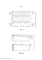
[0035] A figura 12 ilustra um exemplo de fibra de percepção de formato de múltiplos núcleos enrolada helicoidalmente;[0035] Figure 12 illustrates an example of helically wound multi-core shape perception fiber;
[0036] A figura 13 ilustra uma fibra ótica de múltiplos núcleos de teste ilustrativa e não limitadora;[0036] Figure 13 illustrates an optical fiber of multiple test cores illustrative and not limiting;
[0037] A figura 14 ilustra uma seção transversal de uma fibra espiralada onde a posição dos núcleos externos parece girar em torno do núcleo central progredindo descendentemente pelo comprimento da fibra;[0037] Figure 14 illustrates a cross section of a spiral fiber where the position of the outer nuclei appears to rotate around the central nucleus progressing downward through the length of the fiber;
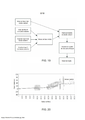
[0038] A figura 15 é um gráfico que ilustra um exemplo de variações na taxa de rotação de uma fibra;[0038] Figure 15 is a graph that illustrates an example of variations in the rate of rotation of a fiber;
[0039] A figura 16 é um gráfico que ilustra um sinal de oscilação ilustrativo com uma variação de fase periódica de uma taxa de rotação fabricada ao longo do comprimento de uma fibra de percepção de formato;[0039] Figure 16 is a graph that illustrates an illustrative oscillation signal with a periodic phase variation of a rotation rate manufactured along the length of a shape perception fiber;
[0040] A figura 17 ilustra como a torção muda a taxa de rotação de uma fibra de percepção de formato com base na orientação da força para a direção de rotação nominal da fibra;[0040] Figure 17 illustrates how the twist changes the rotation rate of a shape perception fiber based on the orientation of the force to the nominal rotation direction of the fiber;
[0041] A figura 18 ilustra um núcleo externo que sofre torção modelada como um cilindro achatado à medida que translada ao longo da superfície;[0041] Figure 18 illustrates an outer core that undergoes torsion modeled like a flattened cylinder as it travels along the surface;
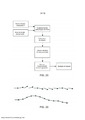
[0042] A figura 19 é um fluxograma ilustrando procedimentos ilustrativos não limitadores para calcular a torção externa ao longo da fibra;[0042] Figure 19 is a flow chart illustrating illustrative non-limiting procedures for calculating the external torsion along the fiber;
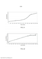
[0043] A figura 20 ilustra um conjunto de dados ilustrativo para um formato genérico que ilustra os procedimentos da figura 19 em maiores detalhes;[0043] Figure 20 illustrates an illustrative data set for a generic format that illustrates the procedures in figure 19 in greater detail;
[0044] A figura 21 é um gráfico que ilustra um desvio leve entre duas curvas de fase;[0044] Figure 21 is a graph showing a slight deviation between two phase curves;
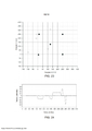
[0045] A figura 22 é um gráfico ilustrando um sinal de torção produzido a partir da figura 21;[0045] Figure 22 is a graph illustrating a torsion signal produced from figure 21;
[0046] A figura 23 ilustra a necessidade de compensação de torção no cálculo de formato;[0046] Figure 23 illustrates the need for torsion compensation in the format calculation;
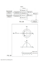
[0047] A figura 24 apresenta curvas de tensão ortogonal ilustrativas para uma fibra localizada em várias dobras que ocorrem no mesmo plano;[0047] Figure 24 shows illustrative orthogonal tension curves for a fiber located in several folds that occur in the same plane;
[0048] A figura 25 ilustra um diagrama de fluxograma descrevendo etapas ilustrativas não limitadoras para o cálculo de formato a partir de tensão;[0048] Figure 25 illustrates a flowchart diagram describing illustrative non-limiting steps for calculating shape from voltage;
[0049] A figura 26 ilustra que se cada um dos múltiplos vetores de orientação for colocado de ponta a ponta uma medição precisa do formato é obtida;[0049] Figure 26 illustrates that if each of the multiple orientation vectors is placed end to end an accurate measurement of the shape is obtained;
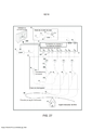
[0050] A figura 27 é um sistema de percepção de formato e posição ótica ilustrativo e não limitador;[0050] Figure 27 is an illustrative and non-limiting optical format and position perception system;
[0051] A figura 28 é um fluxograma ilustrando etapas ilustrativas não limitadoras para calcular a correção de birrefringência;[0051] Figure 28 is a flow chart illustrating illustrative non-limiting steps to calculate the birefringence correction;
[0052] A figura 29 ilustra um perfil de tensão induzido por dobra de uma seção transversal de uma fibra de percepção de formato;[0052] Figure 29 illustrates a tension profile induced by bending a cross section of a shape perception fiber;
[0053] A figura 30 ilustra duas representações de fase comparando um sinal de fase de núcleo central com uma fase média dos núcleos externos;[0053] Figure 30 illustrates two phase representations comparing a central core phase signal with an average phase of the outer cores;
[0054] A figura 31 ilustra uma resposta à tensão ilustrativa para um núcleo externo para um circuito de fibra de 40 mm de diâmetro;[0054] Figure 31 illustrates an illustrative voltage response for an external core for a 40 mm diameter fiber circuit;
[0055] A figura 32 é um gráfico ilustrando uma correção de birrefringência induzida por dobra para o circuito de fibra de 40 mm de diâmetro;[0055] Figure 32 is a graph illustrating a bend-induced birefringence correction for the 40 mm diameter fiber circuit;
[0056] A figura 33 é um gráfico comparando um sinal de torção com e sem uma correção de birrefringência de 2a. ordem;[0056] Figure 33 is a graph comparing a torsion signal with and without a 2a birefringence correction. order;
[0057] A figura 34 ilustra um controlador de polarização de circuito ilustrativo não limitador entre uma fibra de percepção de formato e um sistema de percepção de posição e formato;[0057] Figure 34 illustrates a non-limiting illustrative circuit polarization controller between a shape perception fiber and a position and shape perception system;
[0058] A figura 35 ilustra um sinal em plano para um formato relativamente simples onde 1,4 metros de fibra de percepção de formato são direcionados através de uma única volta de 180 graus com um raio de dobra de 50 mm;[0058] Figure 35 illustrates a plane signal for a relatively simple shape where 1.4 meters of shape perception fiber are directed through a single 180 degree turn with a 50 mm bend radius;
[0059] A figura 36 ilustra três medições fora de plano sucessivas onde entre cada medição, a polarização varia utilizando-se um controlador de polarização;[0059] Figure 36 illustrates three successive out-of-plane measurements where between each measurement, the polarization varies using a polarization controller;
[0060] A figura 37 é um gráfico ilustrando um exemplo no qual duas medições sucessivas do núcleo central, com diferentes estados de polarização de entrada não possuem uma variação significativa na resposta de fase;[0060] Figure 37 is a graph illustrating an example in which two successive measurements of the central core, with different input polarization states do not have a significant variation in the phase response;
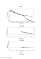
[0061] A figura 38 é um gráfico ilustrando um exemplo no qual duas medições sucessivas de um núcleo externo respondem diferentemente à polarização de entrada fornecendo evidencia para a birrefringência na fibra de sensor de formato;[0061] Figure 38 is a graph illustrating an example in which two successive measurements of an outer core respond differently to the input bias providing evidence for birefringence in the shape sensor fiber;
[0062] A figura 39 é um gráfico ilustrando que a correção da birrefringência aperfeiçoa a precisão do sistema; e[0062] Figure 39 is a graph illustrating that the birefringence correction improves the accuracy of the system; and
[0063] A figura 40 é um gráfico ilustrando que a correção de ambas a birrefringência de primeira e segunda ordem aperfeiçoa a precisão do sistema. Descrição Detalhada[0063] Figure 40 is a graph illustrating that the correction of both first and second order birefringence improves the accuracy of the system. Detailed Description
[0064] Na descrição a seguir, para fins de explicação e não limitação, detalhes específicos são apresentados, tal como nós particulares, entidades funcionais, técnicas, protocolos, padrões, etc. a fim de se fornecer uma compreensão da tecnologia descrita. Será aparente aos versados na técnica que outras modalidades podem ser praticadas além dos detalhes específicos descritos abaixo. Em outros casos, as descrições detalhadas dos métodos, dispositivos, técnicas bem conhecidos, etc. são omitidas de modo a não obscurecer a descrição com detalhes desnecessários. Blocos funcionais individuais são ilustrados nas figuras. Os versados na técnica apreciarão que as funções desses blocos podem ser implementadas utilizando circuitos de hardware individuais, utilizando programas de software e dados em conjunto com um microprocessador programado de forma adequada ou computador de finalidade geral, utilizando circuitos integrados específicos de aplicativo (ASIC) e/ou utilizando um ou mais processadores de sinal digital (DSPs). As instruções de programa de software e dados podem ser armazenadas no meio de armazenamento legível por computador e quando as instruções são executadas por um computador ou outro controle de processador adequado, o computador ou processador realizam as funções.[0064] In the following description, for the purpose of explanation and not limitation, specific details are presented, such as particular nodes, functional entities, techniques, protocols, standards, etc. in order to provide an understanding of the technology described. It will be apparent to those skilled in the art that other modalities can be practiced in addition to the specific details described below. In other cases, detailed descriptions of well-known methods, devices, techniques, etc. they are omitted so as not to obscure the description with unnecessary details. Individual function blocks are illustrated in the figures. Those skilled in the art will appreciate that the functions of these blocks can be implemented using individual hardware circuits, using software programs and data in conjunction with an appropriately programmed microprocessor or general purpose computer, using application-specific integrated circuits (ASIC) and / or using one or more digital signal processors (DSPs). Software program instructions and data can be stored on a computer-readable storage medium and when the instructions are executed by a computer or other suitable processor control, the computer or processor performs the functions.
[0065] Dessa forma, por exemplo, será apreciado pelos versados na técnica que os diagramas em bloco apresentados aqui podem representar vistas conceituais do conjunto de circuito ilustrativo ou outras unidades funcionais consubstanciando os princípios da tecnologia. De forma similar, será apreciado que qualquer fluxograma, diagramas de transição de estado, pseudocódigos, e similares representam vários processos que podem ser substancialmente representados no meio legível por computador e executados por um computador ou processador, caso ou não tal computador ou processador seja explicitamente ilustrado.[0065] In this way, for example, it will be appreciated by those skilled in the art that the block diagrams presented here can represent conceptual views of the set of illustrative circuit or other functional units embodying the principles of technology. Similarly, it will be appreciated that any flowchart, state transition diagrams, pseudocodes, and the like represent various processes that can be substantially represented in a computer-readable medium and executed by a computer or processor, whether or not that computer or processor is explicitly illustrated.
[0066] As funções dos vários elementos incluindo blocos funcionais, incluindo, mas não limitado, aos rotulados ou descritos como "computador", "processador", ou "controlador" podem ser fornecidas através do uso de hardware tal como hardware de circuito e/ou hardware capaz de executar software na forma de instruções codificadas armazenadas no meio legível por computador. Dessa forma, tais funções e blocos funcionais ilustrados devem ser compreendidos como sendo implementados por hardware e/ou implementados por computador, e, dessa forma, implementados por máquina.[0066] The functions of the various elements including function blocks, including, but not limited to, those labeled or described as "computer", "processor", or "controller" can be provided through the use of hardware such as circuit hardware and / or hardware capable of running software in the form of coded instructions stored in a computer-readable medium. Thus, such functions and illustrated functional blocks must be understood as being implemented by hardware and / or implemented by computer, and thus implemented by machine.
[0067] Em termos de implementação de hardware, os blocos funcionais podem incluir ou englobar, sem limitação, hardware de processador de sinal digital (DSP), processador de conjunto de instrução reduzido, conjunto de circuito de hardware (por exemplo, digital ou analógico) incluindo, mas não limitado, a circuitos integrados específicos de aplicativo (ASIC), e (onde adequado) máquinas de situação capazes de realizar tais funções.[0067] In terms of hardware implementation, functional blocks may include or encompass, without limitation, digital signal processor (DSP) hardware, reduced instruction set processor, hardware circuit set (for example, digital or analog) ) including, but not limited to, application specific integrated circuits (ASIC), and (where appropriate) situation machines capable of performing such functions.
[0068] Em termos de implementação de computador, um computador é geralmente compreendido para compreender um ou mais processadores ou um ou mais controladores, e os termos computador e processador e controlador podem ser empregados de forma intercambiável aqui. Quando fornecidas por um computador ou processador ou controlador, as funções podem ser fornecidas por um único computador, processador ou controlador dedicado, por um único computador, processador ou controlador compartilhado, ou por uma pluralidade de computadores, processadores, controladores individuais, alguns dos quais podem ser compartilhados ou distribuídos. Ademais, o uso do termo "processador" ou "controlador" deve ser considerado também como fazendo referência a outro hardware capaz de realizar tais funções e/ou executar o software, tal como, por exemplo, o hardware citado acima. Rastreamento de Fase para Aumentar a Precisão Angular[0068] In terms of computer implementation, a computer is generally understood to comprise one or more processors or one or more controllers, and the terms computer and processor and controller can be used interchangeably here. When provided by a computer or processor or controller, functions can be provided by a single computer, processor or dedicated controller, by a single computer, processor or shared controller, or by a plurality of computers, processors, individual controllers, some of which can be shared or distributed. In addition, the use of the term "processor" or "controller" should also be considered as referring to other hardware capable of performing such functions and / or running the software, such as, for example, the hardware mentioned above. Phase Tracking to Increase Angular Accuracy
[0069] A figura 1 ilustra uma seção transversal de uma fibra de múltiplos núcleos ilustrativa 1 que inclui um núcleo central 2 e três núcleos periféricos 3, 4 e 5 cercados pelo revestimento 6. Esses núcleos 3-5 ilustrados nesse exemplo são espaçados por aproximadamente 120 graus.[0069] Figure 1 illustrates a cross section of an illustrative
[0070] A percepção de formato com uma fibra de múltiplos núcleos assume que as distâncias entre os núcleos na fibra permaneçam constantes, quando observadas em seção transversal, independentemente do formato da fibra. Essa consideração é frequentemente válida visto que o vidro é muito duro e muito elástico. Adicionalmente, a seção transversal da fibra (por exemplo, ~125 mícrons) é pequena em comparação com as dimensões das curvas sofridas pela fibra (por exemplo, raios de dobra superiores a 5 mm). Essa manutenção da posição transversal dos núcleos implica em que toda a deformação da fibra deva ser acomodada pelo alongamento ou compressão dos núcleos. Como ilustrado na figura 2, quando uma fibra de formato é dobrada, um núcleo no exterior 7 da dobra será alongado, enquanto um núcleo no interior 8 da dobra sofrerá compressão.[0070] The perception of shape with a multi-core fiber assumes that the distances between the cores in the fiber remain constant, when observed in cross section, regardless of the shape of the fiber. This consideration is often valid since the glass is very hard and very elastic. In addition, the cross section of the fiber (for example, ~ 125 microns) is small compared to the dimensions of the curves suffered by the fiber (for example, bending radii greater than 5 mm). This maintenance of the transverse position of the nuclei implies that all the deformation of the fiber must be accommodated by the elongation or compression of the nuclei. As illustrated in figure 2, when a shaped fiber is folded, a core on the
[0071] Visto que o comprimento médio de um segmento de núcleo de fibra é considerado inalterado, um exercício de geometria mostra que a mudança na direção (isso é, um vetor que descreve a posição do eixo geométrico central do segmento de fibra), pode ser calculada com base na mudança nos comprimentos de núcleo e distância entre os núcleos. Outros efeitos, tal como coeficiente de tensão ótica, devem ser levados em consideração. O resultado é que a mudança na direção para um determinado segmento da fibra é diretamente proporcional à diferença nas mudanças de comprimento nos núcleos dentro do segmento.[0071] Since the average length of a fiber core segment is considered to be unchanged, an exercise in geometry shows that the change in direction (that is, a vector that describes the position of the central geometric axis of the fiber segment), can be calculated based on the change in core lengths and distance between cores. Other effects, such as the optical voltage coefficient, must be taken into account. The result is that the change in direction for a given fiber segment is directly proportional to the difference in length changes in the cores within the segment.
[0072] A figura 3 ilustra que a dobra na fibra θ é proporcional à tensão ε nos núcleos fora de central onde s é o comprimento de segmento, r é o raio e k é uma constante. A fim de se eliminar a tensão e temperatura da medição, uma medição diferencial entre os núcleos é utilizada.
[0073] A equação acima descreve a mudança angular para um determinado segmento de fibra e como se relaciona com uma mudança na tensão. O movimento para o próximo segmento na fibra, a mudança angular do segmento anterior deve ser adicionado à próxima mudança no ângulo para o próximo segmento para se calcular a direção atual da fibra. Em duas dimensões, todos os ângulos anteriores podem ser acumulados para se encontrar o ângulo de dobra em qualquer local particular ao longo da fibra. A figura 4 ilustra que o ângulo de dobra em qualquer ponto ou localização ao longo da fibra pode ser determinado por uma soma de todos os ângulos levando até o ponto, por exemplo, 05 = Δθi + Δ02 + Δ03 + Δ04 + Δ05. Se houver erro, esse erro se torna maior quanto maior a fibra, crescendo como a raiz quadrada do número de segmentos.[0073] The above equation describes the angular change for a given fiber segment and how it relates to a change in tension. The movement to the next segment in the fiber, the angular change of the previous segment must be added to the next change in the angle to the next segment to calculate the current direction of the fiber. In two dimensions, all of the previous angles can be accumulated to find the bend angle at any particular location along the fiber. Figure 4 illustrates that the bending angle at any point or location along the fiber can be determined by adding all the angles leading to the point, for example, 05 = Δθi + Δ02 + Δ03 + Δ04 + Δ05. If there is an error, this error becomes greater the larger the fiber, growing as the square root of the number of segments.
[0074] Para se evitar esse erro de medição de ângulo acumulado, os inventores conceberam a medição direta da mudança no comprimento de um segmento ao invés da tensão de medição. Matematicamente, a soma dos ângulos então se torna a soma das mudanças de comprimento ao longo da fibra como ilustrado na equação (2) onde L corresponde ao comprimento de fibra.
[0075] Dessa forma, o ângulo em qualquer posição Z ao longo da fibra então se torna linearmente proporcional à diferença entre as mudanças totais no comprimento dos núcleos até essa posição como ilustrado na equação (3).
[0076] Portanto, se a mudança de comprimento total ao longo da fibra puder ser precisamente rastreada de forma contínua, ao invés da soma de cada mudança local individual na tensão, o erro angular pode ser impedido de crescer. Posteriormente, será ilustrado como é possível se rastrear a mudança no comprimento de um núcleo para uma precisão melhor que 10 nm, e se manter essa precisão através de todo o comprimento da fibra. Esse nível de precisão resulta em 0,3 grau de precisão angular com uma separação de 70 mícrons entre os núcleos e, teoricamente, cerca de 0,5% de precisão de posição de comprimento de fibra.[0076] Therefore, if the change in total length along the fiber can be precisely tracked continuously, instead of the sum of each individual local change in tension, the angular error can be prevented from growing. Later, it will be illustrated how it is possible to track the change in the length of a core to an accuracy better than 10 nm, and to maintain that precision across the entire length of the fiber. This precision level results in 0.3 degree of angular accuracy with a separation of 70 microns between the cores and, theoretically, about 0.5% of fiber length position accuracy.
[0077] Infelizmente, a relação cumulativa definida em (3) não se mantém em três dimensões, mas a maior parte dos formatos dimensionais pode ser precisamente representada como uma sucessão de curvas bidimensionais, e na presença de mudanças angulares pequenas (<10 graus), ângulos tridimensionais também possuem essa relação cumulativa simples. Consequentemente, essa abordagem é útil para se determinar as distribuições de erro em três dimensões.[0077] Unfortunately, the cumulative relationship defined in (3) does not remain in three dimensions, but most dimensional formats can be precisely represented as a succession of two-dimensional curves, and in the presence of small angular changes (<10 degrees) , three-dimensional angles also have this simple cumulative relationship. Consequently, this approach is useful for determining error distributions in three dimensions.
[0078] O insight fornecido por esse exercício geométrico é que a mudança de comprimento total como uma função da distância ao longo da fibra de múltiplos núcleos seja utilizada ao invés da tensão local. Em outras palavras, erros relativamente grandes nos valores de tensão local medidos podem ser tolerados desde que toda a tensão medida correspondente à mudança de comprimento total até esse ponto, permaneça precisa. Precisões de nanotensão são alcançadas sem se exigir razões de sinal para ruído extremamente grandes, visto que as distâncias através das quais as nanotensões são calculadas são relativamente grandes (por exemplo, muitos centímetros tal como 10 a 1000 cm.). Como explicado posteriormente na descrição, o rastreamento da mudança no comprimento também pode ser utilizado para determinar a rotação ao longo do comprimento da fibra permitindo precisões mais altas do que o esperado na medição da rotação da fibra, ou ângulo de rotação em torno do eixo geométrico da fibra, também.[0078] The insight provided by this geometric exercise is that the change in total length as a function of the distance along the multi-core fiber is used instead of the local tension. In other words, relatively large errors in the measured local voltage values can be tolerated as long as all the measured voltage corresponding to the change in total length up to that point remains accurate. Nanotension accuracy is achieved without requiring extremely large signal-to-noise ratios, as the distances over which nanotensions are calculated are relatively large (for example, many centimeters such as 10 to 1000 cm.). As explained later in the description, tracking the change in length can also be used to determine the rotation along the length of the fiber allowing higher than expected accuracy in measuring the rotation of the fiber, or angle of rotation around the geometric axis fiber, too.
[0079] Como um sensor, uma fibra ótica pode fornecer medições espacialmente contínuas ao longo de todo o seu comprimento. As medições contínuas são importantes visto que as mudanças de fase ótica são utilizadas para fornecer medições de deslocamento de resolução muito alta. Posteriormente é explicado como o espalhamento intrínseco na fibra pode ser utilizado para alcançar essa medição, mas é conceitualmente mais fácil se começar a explicação com Grade de Bragg de Fibra (FBGs). Uma Graduação Bragg de Fibra é uma modulação periódica do índice de refração da fibra. Cada período tem cerca de meio comprimento de onda de luz na fibra. O comprimento de onda de vácuo da luz é de cerca de 1550 nm, e seu comprimento de onda na fibra é de cerca de 1000 nm. O período de graduação é, portanto, de cerca de 500 nm. Tipicamente, uma graduação Bragg é utilizada como um sensor pela medição de seu espectro refletido. A condição de graduação Bragg é calculada utilizando-se a equação abaixo
[0080] Nessa equação, ÀB representa o comprimento de onda, n é o índice de refração da fibra, e A corresponde ao período de graduação. É considerado que o índice de refração permaneça constante, então o comprimento de onda refletido depende apenas do período de classificação. À medida que a fibra é tensionada, o período de graduação é distorcido, criando uma mudança no comprimento de onda refletido. Dessa forma, para uma mudança no comprimento de onda, é possível se derivar a quantidade de tensão que foi aplicada à fibra. O período de uma graduação Bragg é altamente uniforme, e é conveniente se modelar essa periodicidade como uma modulação sinusoidal. Quando representadas como senoide, as distorções no período de graduação podem ser descritas como mudanças de fase. Para se ilustrar esse conceito, considera-se o exemplo na figura 5 que ilustra que uma fibra contendo grade de Bragg seja tensionada, uma diferença de fase medida a partir de um estado de referência começa a acumular.[0080] In this equation, ÀB represents the wavelength, n is the fiber refractive index, and A corresponds to the graduation period. The refractive index is considered to remain constant, so the reflected wavelength depends only on the classification period. As the fiber is tensioned, the graduation period is distorted, creating a change in the reflected wavelength. Thus, for a change in wavelength, it is possible to derive the amount of tension that was applied to the fiber. The period of a Bragg graduation is highly uniform, and it is convenient to model this periodicity as a sinusoidal modulation. When represented as a sinusoid, distortions in the graduation period can be described as phase changes. To illustrate this concept, consider the example in figure 5 that illustrates that a fiber containing Bragg grid is tensioned, a phase difference measured from a reference state begins to accumulate.
[0081] A representação de uma graduação Bragg tensionada ilustrada na figura 5 ilustra as mudanças locais no índice de refração como segmentos brancos e tracejados alternados. Considerando-se uma graduação Bragg ideal, todos os períodos são idênticos, e a fase de padrão de modulação aumenta linearmente se movendo ao longo da graduação. Em outras palavras, a taxa de mudança de fase com distância é inversamente proporcional ao período de graduação. Se uma pequena parte da graduação for esticada, então a taxa de mudança da fase diminui na parte esticada.[0081] The representation of a tensioned Bragg graduation illustrated in figure 5 illustrates local changes in the refractive index as alternating white and dashed segments. Considering an ideal Bragg graduation, all periods are identical, and the phase of the modulation pattern increases linearly by moving along the graduation. In other words, the rate of phase change with distance is inversely proportional to the graduation period. If a small part of the graduation is stretched, then the rate of change of the phase decreases in the stretched part.
[0082] Na figura 5, o padrão superior apresenta uma graduação não distorcida com uma fase perfeitamente linear como uma função da posição. O padrão alterado inferior apresenta uma distorção de graduação devido à tensão. O gráfico inferior ilustra a diferença na fase entre as duas graduações em cada local. A distorção na graduação resulta em uma mudança de fase no sinal refletido da graduação com relação à fase não distorcida original. Uma mudança de fase de 90 graus é ilustrada. Depois do segmento tensionado, a taxa de mudança retorna para o estado não tensionado. No entanto, a fase nessa região está agora desviada da fase original por uma quantidade igual à mudança de fase total no segmento tensionado. Esse desvio de fase é diretamente proporcional à mudança de comprimento real da fibra ótica.[0082] In figure 5, the upper pattern presents an undistorted graduation with a perfectly linear phase as a function of the position. The lower altered pattern has a gradation distortion due to the stress. The bottom graph illustrates the difference in phase between the two graduations at each location. The distortion in the graduation results in a phase change in the reflected signal of the graduation in relation to the original undistorted phase. A 90 degree phase shift is illustrated. After the tensioned segment, the rate of change returns to the non-tensioned state. However, the phase in that region is now deviated from the original phase by an amount equal to the total phase change in the tensioned segment. This phase shift is directly proportional to the change in the actual length of the optical fiber.
[0083] Essa ilustração ilustra apenas quinze períodos de graduação. Visto que um período tem 500 nm, isso soma 7,5 um de comprimento. O estiramento da fibra para indução de uma mudança de fase de 90 graus desloca o restante das graduações não tensionadas por um quarto de um período, ou 125 nm. Uma medição de Reflectometria de Domínio de Frequência Ótica (OFDR) pode ter uma resolução espacial da ordem de 50 mícrons. Em outras palavras, cada ponto de dados OFDR, ou índice, é separado por 50 um. Logo, uma distorção de 125 nm resulta em apenas uma fração pequena de uma mudança de índice OFDR na posição real da graduação. Enquanto a mudança de 125 nm na posição não é detectável propriamente dita, a mudança de fase de 90 graus é relativamente facilmente medida com um sistema OFDR.[0083] This illustration illustrates only fifteen graduation periods. Since a period is 500 nm, this adds up to 7.5 μm in length. Stretching the fiber to induce a 90 degree phase shift displaces the rest of the unstressed graduations by a quarter of a period, or 125 nm. An Optical Frequency Domain Reflectometry (OFDR) measurement can have a spatial resolution of the order of 50 microns. In other words, each OFDR data point, or index, is separated by 50 µm. Thus, a 125 nm distortion results in only a small fraction of an OFDR index change in the actual position of the graduation. While the 125 nm change in position is not detectable per se, the 90 degree phase change is relatively easily measured with an OFDR system.
[0084] OFDR pode, portanto, ser utilizado para medir as distorções dentro de grade de Bragg, e, ao invés de apenas medir a taxa de mudança de fase (isto é, comprimento de onda), a fase absoluta pode ser medida, e a partir da fase, as mudanças de distância em cada segmento ao longo do núcleo da fibra. Isso é importante para medições precisas de formato em uma situação na qual a fase na graduação é observada como tendo mudado, enquanto a posição da graduação não ilustra qualquer mudança discernível. Tecnologias de medição de fibra ótica convencionais tratam a mudança de fase e de posição como efeitos separados.[0084] OFDR can therefore be used to measure distortions within the Bragg grid, and, instead of just measuring the rate of phase change (ie wavelength), the absolute phase can be measured, and from the phase, the distance changes in each segment along the fiber core. This is important for accurate shape measurements in a situation in which the graduation stage is seen to have changed, while the graduation position does not illustrate any discernible change. Conventional fiber optic measurement technologies treat phase and position change as separate effects.
[0085] Uma forma de se visualizar a relação entre a mudança de fase e a posição é imaginar que a fase do sinal ótico é representada pelo ponteiro de segundos de um relógio, e que a localização ao longo da fibra no índice é representada pelo ponteiro das horas de um relógio. A figura 6 ilustra um relógio sem ponteiro de minutos. Tal relógio dificulta a determinação do tempo para uma resolução de um minuto. Mas esse relógio ainda é útil para temporização de ambos os eventos de curta duração com o ponteiro de segundos e eventos de longa duração com o ponteiro de horas. A falta de um ponteiro de minutos, não é útil para medição de eventos de duração média intermediários (por exemplo, 1 hora e 12 minutos e 32 segundos) para a precisão de um segundo. Essa dificuldade de conexão de duas escalas tem feito com que os sistemas de medição ótica convencionais tratem os fenômenos separadamente.[0085] One way to visualize the relationship between the phase change and the position is to imagine that the phase of the optical signal is represented by the second hand of a watch, and that the location along the fiber in the index is represented by the hand the time on a clock. Figure 6 illustrates a clock without a minute hand. Such a watch makes it difficult to determine the time for a one-minute resolution. But this watch is still useful for timing both short duration events with the second hand and long duration events with the hour hand. The lack of a minute hand is not useful for measuring intermediate intermediate duration events (for example, 1 hour and 12 minutes and 32 seconds) for the accuracy of one second. This difficulty in connecting two scales has made conventional optical measurement systems treat phenomena separately.
[0086] Essa analogia com o relógio ajuda a esclarecer porque uma medição contínua é necessária ao longo de todo o comprimento da fibra. Pelo monitoramento da posição do ponteiro de segundos continuamente, o número de revoluções completas pode ser medido, o que permite o monitoramento simultâneo de durações longas com uma alta precisão. Conectando-se a analógica de relógio com a discussão anterior das grade de Bragg, cada 360 graus, ou 2π, de mudança de fase é igual a uma mudança de 500 nm na localização. Pelo rastreamento contínuo de fase ao longo da fibra ótica, ambas as tensões locais e as mudanças de comprimento totais da fibra ótica podem ser medidas com uma precisão muito alta.[0086] This analogy with the clock helps to clarify why a continuous measurement is necessary along the entire length of the fiber. By monitoring the position of the second hand continuously, the number of complete revolutions can be measured, which allows simultaneous monitoring of long durations with high precision. Connecting the clock analog to the previous discussion of the Bragg grids, each 360 degrees, or 2π, of phase change is equal to a 500 nm change in location. By continuous phase tracking along the optical fiber, both local stresses and the total length changes of the optical fiber can be measured with very high accuracy.
[0087] Um desafio no rastreamento de fase continuamente é que a resolução da medição deve ser suficiente de modo que a fase não mude de um segmento para o próximo por mais de 2πA figura 7 ilustra como essa falta de resolução pode ser problemática visto que não existe forma de se distinguir, por exemplo, entre uma mudança de π/3 e uma mudança de π/3+2π. Logo, duas mudanças de fase diferentes parecem ter o mesmo valor no círculo unitário. Em outras palavras, um erro de um índice seria incorrido em uma conta de 2π revoluções totais. Nesse exemplo, a medição da mudança geral no comprimento da fibra ótica seria deficiente por 500 nm.[0087] A challenge in phase tracking continuously is that the measurement resolution must be sufficient so that the phase does not change from one segment to the next for more than 2π. Figure 7 illustrates how this lack of resolution can be problematic since it does not there is a way to distinguish, for example, between a change of π / 3 and a change of π / 3 + 2π. Therefore, two different phase changes appear to have the same value in the unit circle. In other words, an index error would be incurred on an account of 2π total revolutions. In this example, the measurement of the overall change in optical fiber length would be deficient by 500 nm.
[0088] Logo, é importante que um sistema de percepção de formato tenha uma resolução suficiente para garantir a capacidade de se rastrear a fase ao longo de todo o comprimento de uma fibra de percepção de formato para se garantir a precisão de um sistema de percepção de formato.[0088] Therefore, it is important that a format perception system has sufficient resolution to guarantee the ability to track the phase along the entire length of a format perception fiber to guarantee the accuracy of a perception system. format.
[0089] Como explicado acima, o uso típico de um FBG para perceber envolve mudanças de medição no espectro refletido de grade de Bragg individuais espaçadas em algum intervalo descendendo por uma fibra. A tensão é derivada para cada seção da fibra a partir da medição para cada graduação Bragg. Para a percepção de formato utilizando-se FBGs, cada medição de tensão indica quanto um determinado segmento é dobrado e em que direção. Essa informação é somada para todos os segmentos medidos para fornecer a posição e/ou formato de fibra total. No entanto, utilizando-se esse método, um erro em cada segmento acumula ao longo da fibra. Quanto maior a fibra, maior o erro na medição. Esse erro utilizando múltiplas grade de Bragg limita a velocidade de operação e a faixa de aplicações.[0089] As explained above, the typical use of an FBG to perceive involves measurement changes in the reflected spectrum of individual Bragg grids spaced at some interval descending by a fiber. The stress is derived for each fiber section from the measurement for each Bragg grade. For format perception using FBGs, each voltage measurement indicates how much a given segment is bent and in which direction. This information is added for all measured segments to provide the total fiber position and / or shape. However, using this method, an error in each segment accumulates along the fiber. The larger the fiber, the greater the measurement error. This error using multiple Bragg grids limits the speed of operation and the range of applications.
[0090] Se houver uma graduação contínua ao longo da fibra, então a fase pode ser rastreada em cada ponto ao longo da fibra como descrito acima. O rastreamento da fase ao longo de todo o comprimento do núcleo evita acúmulo de erro. A invés do acúmulo de erro como a raiz quadrada do número de segmentos de fibra, o erro de comprimento total permanece constante em uma fração do comprimento de onda ótica no material. Como mencionado anteriormente, um comprimento de onda de luz pode ter cerca de 1550 nm em um vácuo e cerca de 1000 nm na fibra, o que é efetivamente 500 nm em reflexo. Uma razão de sinal para ruído de 50 fornece uma precisão de 10 nm devido à natureza de percurso de ida e volta (reflexo) da medição. A precisão da tensão resultante através de um metro de fibra será de 10 nanotensão.[0090] If there is a continuous graduation along the fiber, then the phase can be traced at each point along the fiber as described above. Tracking the phase along the entire length of the core prevents error build-up. Instead of the accumulation of error as the square root of the number of fiber segments, the total length error remains constant at a fraction of the optical wavelength in the material. As mentioned earlier, a wavelength of light can be about 1550 nm in a vacuum and about 1000 nm in the fiber, which is effectively 500 nm in reflection. A signal-to-noise ratio of 50 provides an accuracy of 10 nm due to the round-trip (reflection) nature of the measurement. The accuracy of the resulting tension through a meter of fiber will be 10 nanotension.
[0091] O espalhamento Rayleigh pode ser visualizado como uma graduação Bragg com fases randômicas e amplitudes ou uma graduação Bragg consistindo totalmente de defeitos. Esse padrão de espalhamento Rayleigh enquanto aleatório, é fixado dentro de um núcleo de fibra quando esse núcleo é fabricado. A tensão aplicada a uma fibra ótica causa mudanças ou distorções no padrão de espalhamento Rayleigh. Essas distorções induzidas do padrão de espalhamento Rayleigh podem ser utilizadas como uma medição de tensão de alta resolução para percepção de formato pela comparação de uma digitalização de referência da fibra quando a fibra está em um formato conhecido com uma nova digitalização da fibra quando a mesma foi dobrada ou tensionada.[0091] Rayleigh scattering can be visualized as a Bragg gradation with random phases and amplitudes or a Bragg grading consisting entirely of defects. This Rayleigh scattering pattern, while random, is fixed within a fiber core when that core is manufactured. The voltage applied to an optical fiber causes changes or distortions in the Rayleigh scattering pattern. These induced distortions of the Rayleigh scattering pattern can be used as a high resolution stress measurement for shape perception by comparing a fiber reference scan when the fiber is in a known format with a new fiber scan when it was bent or tensioned.
[0092] A figura 8 ilustra resultados ilustrativos de tal comparação. Essa figura ilustra a diferença de fase do sinal de espalhamento Rayleigh entre uma digitalização de referência e uma digitalização de medição no começo de uma seção de fibra que entra em uma região que está sob tensão. Os dados são representados como uma função do índice de fibra, que representa a distância ao longo da fibra. Uma vez que a região de tensão é adentrada, a diferença de fase começa a acumular. Visto que π e -π possuem o mesmo valor no círculo unitário, o sinal sofre "envolvimento" a cada múltiplo de 2π à medida que a diferença de fase cresce ao longo do comprimento da fibra. Isso pode ser observado em torno do índice 3550 onde os valores para a esquerda do mesmo estão se aproximando de π, e então, subitamente, os valores estão em -π. Como ilustrado, cada envolvimento representa cerca de 500 nm de mudança de comprimento na fibra. Visto que um índice representa cerca de 50 mícrons de comprimento, leva cerca de cem envolvimentos da fase para cumular um índice total de mudança de retardo entre as medições e a referência.[0092] Figure 8 illustrates illustrative results of such a comparison. This figure illustrates the phase difference of the Rayleigh scattering signal between a reference scan and a measurement scan at the beginning of a section of fiber that enters a region that is under tension. The data is represented as a function of the fiber index, which represents the distance along the fiber. Once the voltage region is entered, the phase difference begins to accumulate. Since π and -π have the same value in the unit circle, the signal is "wrapped" at each multiple of 2π as the phase difference grows along the length of the fiber. This can be seen around the 3550 index where the values to the left of it are approaching π, and then, suddenly, the values are at -π. As illustrated, each wrap represents about 500 nm of change in length in the fiber. Since an index is about 50 microns in length, it takes about one hundred phase envelopes to cumulate a total delay change index between measurements and the reference.
[0093] Os dados na figura 9 são do mesmo conjunto de dados que os da figura 8, mas a partir de uma área mais para baixo da fibra em torno de cerca de 35 envolvimentos de fase, ou, aproximadamente um terço de um índice. O ruído nos dados de diferença de fase tem aumentado e é causado pela mudança crescente entre os padrões de espalhamento de medição e referência. Isso reduz a coerência entre os dados de referência e medição utilizados para determinar a diferença de fase. Se a localização aparente de um segmento de fibra de espalhamento individual mudar por mais de um índice, então a coerência entre a referência e medição é perdida, e nenhuma medição de tensão pode ser obtida a partir da comparação dos sinais espalhados.[0093] The data in figure 9 are from the same data set as in figure 8, but from a lower area of the fiber around about 35 phase envelopes, or approximately one third of an index. The noise in the phase difference data has increased and is caused by the increasing change between the measurement and reference spread patterns. This reduces the consistency between the reference and measurement data used to determine the phase difference. If the apparent location of an individual scattering fiber segment changes by more than one index, then the consistency between the reference and measurement is lost, and no voltage measurement can be obtained by comparing the scattered signals.
[0094] Portanto, os dados de referência devem ser combinados com os dados de medição pela compensação de mudança devido à tensão ao longo da fibra. No caso de um índice ser de cerca de 50 mícrons, através de um segmento de um metro, isso soma apenas 50 partes por milhão, que não é uma tensão grande. De fato, o peso da fibra propriamente dita pode induzir tensões dessa ordem. Além disso, uma mudança na temperatura de apenas poucos graus Celsius pode induzir uma mudança similar. Portanto, essa mudança no índice deve ser compensada no cálculo de distorção de núcleo.[0094] Therefore, the reference data must be combined with the measurement data by the change compensation due to the tension along the fiber. In the case of an index being about 50 microns, across a segment of one meter, this adds up to just 50 parts per million, which is not a big strain. In fact, the weight of the fiber itself can induce stresses of this order. In addition, a change in temperature of just a few degrees Celsius can induce a similar change. Therefore, this change in the index must be compensated for in the calculation of core distortion.
[0095] Uma mudança como resultado da tensão em uma expansão física dos segmentos individuais que resulta em um tempo aumentado de voo da luz espalhada. A mudança entre a referência e a medição é referida como retardo. O retardo pode ser compensado pela consulta a um modelo de como uma mudança no retardo para qualquer ponto no núcleo de percepção afeta o sinal refletido a partir desse ponto. Se um campo (luz) estiver oscilando em uma frequência, v, e sofrer um retardo de T, então a fase ótica como uma função do retardo é fornecida por:
[0096] Se a fase ótica, Φ, for representada como uma função da frequência, v, uma linha reta é obtida que forma uma interseção com a origem. Na prática, a passagem através de um material tal como vidro distorce essa curva de uma linha perfeita, o que deve ser mantido em mente quando da comparação do valor medido, com os valores previstos por esse modelo. Mas para fins imediatos, esse modelo é suficiente. A figura 10 ilustra essa fase para dois retardos diferentes. Em um exemplo, o sistema de medição não limitador utilizando o princípio descrito acima, uma varredura típica de laser deve cobrir uma faixa de 192,5 a 194,5 THz. Essas frequências representam uma varredura de 1542 nm (194,5 THz) para 1558 nm (192,5 THz), que foi uma faixa de varredura de teste para uma aplicação de sensor de formato de teste não limitador. Através dessa faixa de interesse, a fase para um retardo determinado varre através de uma faixa de ΔΦ. Para os dois retardos ilustrados, n e x2, a diferença nessa faixa de varredura, ΔΦ2-ΔΦ1 é inferior à mudança na fase da frequência central (193,5 THz), rotulada dΦ. O fator entre a mudança na fase da frequência central e a mudança na fase de faixa de varredura será a razão da frequência central para a faixa de varredura de frequência. Nesse caso ilustrativo, a razão é de 96,7.[0096] If the optical phase, Φ, is represented as a function of the frequency, v, a straight line is obtained that forms an intersection with the origin. In practice, the passage through a material such as glass distorts this curve from a perfect line, which must be kept in mind when comparing the measured value with the values predicted by that model. But for immediate purposes, this model is sufficient. Figure 10 illustrates this phase for two different delays. In one example, the non-limiting measurement system using the principle described above, a typical laser scan should cover a range of 192.5 to 194.5 THz. These frequencies represent a scan from 1542 nm (194.5 THz) to 1558 nm (192.5 THz), which was a test scan range for a non-limiting test format sensor application. Through this range of interest, the phase for a given delay sweeps across a range of ΔΦ. For the two illustrated delays, n and x2, the difference in this scan range, ΔΦ2-ΔΦ1 is less than the change in the central frequency phase (193.5 THz), labeled dΦ. The factor between the change in the phase of the central frequency and the change in the phase of the scanning range will be the ratio of the central frequency to the frequency scanning range. In this illustrative case, the ratio is 96.7.
[0097] Na aplicação de teste ilustrativa, a faixa de varredura, Δv, determina a resolução espacial, δx, da medição. Em outras palavras, determina o comprimento de um índice no domínio de tempo. Esses são relacionados por uma relação invertida:
[0098] Para a faixa de frequência ilustrativa descrita acima, o comprimento de um índice é de 0,5 ps, ou 50 mícrons no vidro. Na frequência central, uma mudança de fase de 2 π é induzida por uma mudança no retardo de apenas 0,00516 ps ou 516 nm no vidro. Uma mudança de fase de 2π, então, representa apenas uma mudança de índice fracionada dos dados de domínio de tempo. A fim de mudar o retardo por um índice no domínio de tempo, o retardo deve mudar o suficiente para induzir uma mudança de fase na frequência central de 96,7 x 2π.[0098] For the illustrative frequency range described above, the length of an index is 0.5 ps, or 50 microns on the glass. At the center frequency, a 2 π phase change is induced by a delay change of only 0.00516 ps or 516 nm in the glass. A 2π phase change, then, represents only a fractional index change of the time domain data. In order to change the delay by an index in the time domain, the delay must change enough to induce a phase shift at the center frequency of 96.7 x 2π.
[0099] Esses exemplos ilustram que uma mudança de fase linear representa uma mudança na localização dos eventos no domínio de tempo, ou retardo. Como observado acima, uma mudança de um índice irá distorcer completamente as medições da mudança de fase ao longo do comprimento da fibra. Para se comparar adequadamente as fases, então, essas mudanças devem ser compensadas à medida que ocorrem, e os dados de referência devem ser alinhados com os dados de medição descendo por todo o comprimento do núcleo. Para corrigir essa degradação de coerência, uma mudança temporal dos dados de referência é necessária. Isso pode ser realizado pela multiplicação de dados de referência para um segmento determinado, rn, por uma fase linear. Aqui n representa o índice no domínio de tempo, ou o aumento da distância ao longo da fibra. A inclinação dessa correção de fase, y, é encontrada pela realização de um encaixe linear nos valores de retardo anteriores. O desvio de fase nesse termo de correção, Φ, é selecionado de modo que o valor médio dessa fase seja igual a zero.
[00100] A figura 11 ilustra a diferença de fase corrigida através de uma seção de fibra onde um terço de uma mudança de índice ocorreu. A diferença de fase nesse local mantém a mesma razão de sinal para ruído como a parte mais próxima da fibra. Pela aplicação de uma mudança temporal com base no retardo em uma distância particular, a coerência foi recuperada reduzindo-se o ruído de fase.[00100] Figure 11 illustrates the phase difference corrected through a fiber section where a third of an index change has occurred. The phase difference at that location maintains the same signal-to-noise ratio as the part closest to the fiber. By applying a temporal change based on the delay at a particular distance, coherence was recovered by reducing the phase noise.
[00101] O rastreamento de distorções no espalhamento Rayleigh da fibra ótica fornece medições contínuas de alta resolução da tensão. A geometria da fibra de percepção de formato de múltiplos núcleos é utilizada para explicar como essa estrutura de múltiplos núcleos permite as medições de ambas a dobra e a direção de dobra ao longo do comprimento de fibra.[00101] The tracking of distortions in the Rayleigh scattering of the optical fiber provides continuous high-resolution measurements of the voltage. The geometry of the multi-core shape perception fiber is used to explain how this multi-core structure allows measurements of both the bend and the bend direction along the fiber length.
[00102] A fibra ótica contém múltiplos núcleos em uma configuração que permite a percepção de ambas uma torção externa e tensão independentemente da direção de dobra. Uma modalidade ilustrativa não limitadora de tal fibra é ilustrada na figura 1 e descrita abaixo. A fibra contém quatro núcleos. Um núcleo é posicionado ao longo do eixo geométrico central da fibra. Os outros três núcleos externos são colocados de forma concêntrica com relação a esse núcleo em intervalos de 120 graus em uma separação de 70 um. Os núcleos externos são girados com relação ao núcleo central criando um hélice com um período de 66 voltas por metro. Uma ilustração dessa fibra de percepção de formato de múltiplos núcleos helicoidalmente envolvida é apresentada na figura 12. Uma representação de uma fibra ótica de múltiplos núcleos de teste não limitadora utilizada nessa discussão é apresentada na figura 13.[00102] The optical fiber contains multiple cores in a configuration that allows the perception of both an external twist and tension regardless of the bending direction. An illustrative non-limiting embodiment of such a fiber is illustrated in figure 1 and described below. The fiber contains four cores. A core is positioned along the central geometric axis of the fiber. The other three outer cores are placed concentric with respect to that core at 120 degree intervals in a 70 µm separation. The outer cores are rotated with respect to the central core creating a propeller with a period of 66 turns per meter. An illustration of this helically wrapped multi-core shape perception fiber is shown in figure 12. A representation of a non-limiting test multi-core optical fiber used in this discussion is shown in figure 13.
[00103] Outro exemplo não limitador de uma fibra de percepção de formato contém mais de três núcleos externos para facilitar a fabricação da fibra ou para adquirir dados adicionais para aperfeiçoar o desempenho do sistema.[00103] Another non-limiting example of a format perception fiber contains more than three external cores to facilitate the manufacture of the fiber or to acquire additional data to improve the performance of the system.
[00104] Em uma seção transversal de uma fibra espiralada, a posição de cada núcleo externo parece girar em torno de um núcleo central que progride descendentemente pelo comprimento da fibra como ilustrado na figura 14.[00104] In a cross section of a spiral fiber, the position of each outer core appears to revolve around a central core that progresses downward through the length of the fiber as illustrated in figure 14.
[00105] Para se traduzir os sinais de tensão dos núcleos externos em dobra e direção de dobra, a posição de rotação de um núcleo externo deve ser determinada com um alto grau de precisão. Considerando-se uma taxa de rotação constante do hélice (ver figura 12), a posição dos núcleos externos pode ser determinada com base na distância ao longo da fibra. Na prática, a fabricação da fibra espiralada introduz alguma variação na taxa de rotação pretendida. A variação na taxa de rotação ao longo do comprimento da fibra causa um distanciamento angular da variação linear esperada a partir da taxa de rotação nominal, e esse distanciamento angular é referido como "oscilação" e simbolizada como um sinal de oscilação W (z).[00105] In order to translate the stress signals from the outer cores into fold and fold direction, the rotation position of an outer core must be determined with a high degree of accuracy. Considering a constant rate of rotation of the propeller (see figure 12), the position of the outer cores can be determined based on the distance along the fiber. In practice, the manufacture of the coiled fiber introduces some variation in the desired rate of rotation. The variation in the rate of rotation along the length of the fiber causes an angular distance from the expected linear variation from the nominal rate of rotation, and that angular distance is referred to as "oscillation" and symbolized as an oscillation signal W (z).
[00106] Uma fibra de teste ilustrativa fabricada com uma geométrica de múltiplos núcleos helicoidais possui um grau muito alto de precisão em termos de taxa de rotação média, 66 voltas por metro. No entanto, através de distancias curtas (por exemplo, 30 cm) a taxa de rotação varia de forma significativa, e pode fazer com que a posição angular varie tanto quanto 12 graus a partir de uma mudança de fase puramente linear com a distância. Esse erro na taxa de rotação é medido pela colocação da fibra em uma configuração que causará uma dobra contínua em um único plano, como é o caso de uma fibra espiralada em uma superfície plana. Quando a fibra é colocada em tal espiral, um núcleo helicoidal alternará entre tensão e compressão à medida que percorre através da parte externa de uma dobra e a parte interna de uma dobra. Se a distorção de fase for representada X distância, um sinal sinusoidal é formado com um período que combina a taxa de rotação da fibra. Variações na fabricação da fibra de múltiplos núcleos podem ser detectadas como pequenas mudanças na fase a partir da taxa de rotação constante esperada da fibra.[00106] An illustrative test fiber manufactured with a geometric multiple helical cores has a very high degree of accuracy in terms of average rotation rate, 66 turns per meter. However, over short distances (for example, 30 cm) the rate of rotation varies significantly, and can cause the angular position to vary by as much as 12 degrees from a purely linear phase change with distance. This error in the rotation rate is measured by placing the fiber in a configuration that will cause a continuous fold in a single plane, as is the case with a spiral fiber on a flat surface. When the fiber is placed in such a spiral, a helical core will alternate between tension and compression as it travels through the outside of a fold and the inside of a fold. If the phase distortion is represented X distance, a sinusoidal signal is formed with a period that matches the rate of rotation of the fiber. Variations in the fabrication of the multi-core fiber can be detected as small changes in the phase from the expected constant rotation rate of the fiber.
[00107] Um exemplo dessas variações na taxa de rotação é ilustrado na figura 15. A curva sólida são dados de fase (sinal de dobra) tirados de um espiral plano, e a linha pontilhada é uma senoide perfeita gerada na mesma frequência e fase que o hélice. Note-se que no começo do segmento de dados as curvas estão em fase com os cruzamentos zero alinhados. Pelo meio do segmento, a curva sólida avança ligeiramente adiante da curva pontilhada, mas pelo final do segmento de dados, um desvio significativo é observado. Se o componente DC do sinal de fase for removido, e uma mudança de fase calculada, a diferença entre esses dois sinais é significativa e de alguma forma periódica.[00107] An example of these variations in the rotation rate is illustrated in figure 15. The solid curve is phase data (bend signal) taken from a flat spiral, and the dotted line is a perfect sinusoid generated at the same frequency and phase as the propeller. Note that at the beginning of the data segment the curves are in phase with the zero crossings aligned. Through the middle of the segment, the solid curve advances slightly ahead of the dotted curve, but by the end of the data segment, a significant deviation is observed. If the DC component of the phase signal is removed, and a phase change is calculated, the difference between these two signals is significant and somewhat periodic.
[00108] A figura 16 ilustra um sinal de Oscilação ilustrativo, W(z), com uma variação periódica de uma taxa de rotação fabricada ao longo do comprimento de uma fibra de percepção de formato. A variação de fase é ilustrada como uma função do comprimento no índice de fibra. O conjunto de dados ilustrativo representa cerca de três metros de fibra. Da ordem de um terço de um metro, uma periodicidade na natureza da taxa de rotação da fibra é detectada. Através do comprimento da fibra, uma taxa de rotação média consistente da fibra é produzida, mas essas pequenas flutuações devem ser medidas a fim de se interpretar corretamente os dados de fase produzidos pela fibra torcida de múltiplos núcleos. Essa medição na mudança na taxa de rotação ou "oscilação" pode ser reproduzida e é importante para o cálculo do formato de acordo com a fabricação prática da fibra.[00108] Figure 16 illustrates an illustrative Oscillation signal, W (z), with a periodic variation of a rotation rate manufactured along the length of a shape perception fiber. Phase variation is illustrated as a function of length in the fiber index. The illustrative data set represents about three meters of fiber. On the order of a third of a meter, a periodicity in the nature of the fiber's rotation rate is detected. Through the fiber length, a consistent average rotation rate of the fiber is produced, but these small fluctuations must be measured in order to correctly interpret the phase data produced by the multi-core twisted fiber. This measurement in the change in the rotation rate or "oscillation" can be reproduced and is important for calculating the shape according to the practical manufacture of the fiber.
[00109] As forças de torção aplicadas à fibra também possuem o potencial de induzir uma mudança rotativa dos núcleos externos. Para se mapear adequadamente os sinais de tensão dos núcleos para as direções de dobra corretas, ambas a oscilação e torção aplicada devem ser medidas ao longo de todo o comprimento da fibra de percepção de formato. A geometria da fibra de múltiplos núcleos espiralada permite a medição direta da torção ao longo do comprimento da fibra em adição à tensão induzida por dobra como será descrito abaixo.[00109] The torsional forces applied to the fiber also have the potential to induce a rotational change in the outer cores. In order to properly map the stress signals from the cores to the correct bend directions, both the oscillation and twist applied must be measured along the entire length of the shape perception fiber. The spiral geometry of the multi-core fiber allows direct measurement of the twist along the length of the fiber in addition to the bend-induced tension as will be described below.
[00110] Se uma fibra de múltiplos núcleos for girada enquanto é puxada, o núcleo central é essencialmente não perturbado, enquanto os núcleos externos seguem um percurso helicoidal descendentemente pela fibra como ilustrado no centro da figura 17. Se tal estrutura for então submetida à tensão de torção, o comprimento do núcleo central permanece constante. No entanto, se a direção da tensão de torção combinar com a retirada do hélice, o período do hélice aumenta e os núcleos externos serão alongados uniformemente como ilustrado no topo da figura 17. Inversamente, se a direção de torção for contrária à retirada do hélice, os núcleos externos são "desenrolados" e sofrem uma compressão ao longo de seu comprimento como ilustrado no fundo da figura 17.[00110] If a multi-core fiber is spun while being pulled, the central core is essentially undisturbed, while the outer cores follow a helical path downwardly through the fiber as illustrated in the center of figure 17. If such a structure is then subjected to tension of torsion, the length of the central core remains constant. However, if the direction of the torsion stress matches the propeller withdrawal, the propeller period increases and the outer cores will be stretched evenly as shown at the top of figure 17. Conversely, if the torsion direction is contrary to the propeller withdrawal , the outer cores are "unrolled" and compressed along their length as illustrated at the bottom of figure 17.
[00111] Para se derivar a sensibilidade da configuração de múltiplos núcleos à torção, a mudança no comprimento que um núcleo externo sofrerá devido à torção é estimada. Um segmento de fibra é modelado como um cilindro. O comprimento L do cilindro corresponde ao tamanho de segmento, enquanto que a distância do núcleo central para um núcleo externo representa o raio r do cilindro. A superfície de um cilindro pode ser representada como um retângulo se se fatiar o cilindro longitudinalmente e então achatar a superfície. O comprimento da superfície é igual ao comprimento de segmento L enquanto a largura da superfície corresponde à circunferência do cilindro 2πr. Quando a fibra é torcida, o ponto final da fibra move em torno do cilindro, enquanto o ponto inicial permanece fixo. Projetado na superfície achatada, o núcleo torcido forma uma linha diagonal que é mais longa do que o comprimento L do retângulo. Essa mudança no comprimento do núcleo externo é relacionada com a torção na fibra.[00111] To derive the sensitivity of the configuration of multiple cores to torsion, the change in length that an external core will undergo due to torsion is estimated. A fiber segment is modeled like a cylinder. The length L of the cylinder corresponds to the segment size, while the distance from the central core to an external core represents the radius r of the cylinder. The surface of a cylinder can be represented as a rectangle by slicing the cylinder longitudinally and then flattening the surface. The length of the surface is equal to the length of segment L while the width of the surface corresponds to the circumference of the cylinder 2πr. When the fiber is twisted, the end point of the fiber moves around the cylinder, while the start point remains fixed. Projected on the flattened surface, the twisted core forms a diagonal line that is longer than the length L of the rectangle. This change in the length of the outer core is related to the twist in the fiber.
[00112] A figura 18 ilustra um núcleo externo que sofre a torção e pode ser modelado como um cilindro achatado à medida que translada ao longo da superfície. A partir da superfície achatada acima, o seguinte pode ser ilustrado:
[00113] Na equação acima, ôd é a mudança no comprimento do núcleo externo devido à mudança na rotação dΦ. da fibra a partir de seu estado espiralado. A distância radial entre um núcleo central e um núcleo externo é representada por r, e 2π/L é a taxa de rotação da fibra helicoidal em rotação por comprimento unitário.[00113] In the above equation, ôd is the change in the length of the outer core due to the change in rotation dΦ. of the fiber from its spiral state. The radial distance between a central core and an outer core is represented by r, and 2π / L is the rotation rate of the helical fiber in rotation per unit length.
[00114] A distância mínima detectável é considerada nesse exemplo como sendo um comprimento de um radiano de uma onda ótica. Para o sistema de teste ilustrativo, o comprimento de onda operacional é de 1550 nm, e o índice de vidro é de cerca de 1,47, resultando em uma distância mínima detectável de aproximadamente 10 nm. Se o raio for de 70 mícrons e o período do hélice for de 15 mm, então a equação (8) indica que a fibra de sensor de formato possui uma sensibilidade à torção de 0,3 grau. Se a fibra de percepção começar seu formato pela rotação imediata por 90 graus, de modo que o erro devido à torção seja maximizado, então o erro de posição resultante será de 0,5% do comprimento de fibra. Na maior parte das aplicações, dobras de 90 graus não ocorrem no começo da fibra, e, portanto, o erro será inferior a 0,5%.[00114] The minimum detectable distance is considered in this example to be a radian length of an optical wave. For the illustrative test system, the operating wavelength is 1550 nm, and the glass index is about 1.47, resulting in a minimum detectable distance of approximately 10 nm. If the radius is 70 microns and the helix period is 15 mm, then equation (8) indicates that the shape sensor fiber has a 0.3 degree torsional sensitivity. If the perception fiber starts its shape by immediate rotation by 90 degrees, so that the error due to torsion is maximized, then the resulting position error will be 0.5% of the fiber length. In most applications, 90 degree bends do not occur at the beginning of the fiber, and therefore the error will be less than 0.5%.
[00115] A sensibilidade da medição de torção é baseada na sensibilidade de um núcleo único, mas a percepção da torção ao longo do comprimento da fibra depende de todos os quatro núcleos. Se a diferença na mudança no comprimento entre a média dos núcleos externos e o núcleo central for conhecida, então a torção (em termos de número absoluto de graus) presente na fibra pode ser calculada.[00115] The sensitivity of torsion measurement is based on the sensitivity of a single core, but the perception of torsion along the length of the fiber depends on all four cores. If the difference in the change in length between the mean of the outer cores and the central core is known, then the torsion (in terms of the absolute number of degrees) present in the fiber can be calculated.
[00116] A torção externa ao longo da fibra pode ser calculada utilizando-se procedimentos ilustrativos não limitadores destacados no fluxograma ilustrado na figura 19. Os sinais de fase para todos os quatro núcleos A-D são determinados, e os sinais para os núcleos externos B-D são medidos. O cálculo da torção extrínseca é realizado pela comparação da média dos sinais de fase de núcleo externos com o núcleo central. Se a fibra sofrer uma força de torção, todos os núcleos externos sofrem um alongamento ou compressão similar determinados pela orientação da força para a direção de rotação do hélice. O núcleo central não sofre uma mudança de comprimento como resultado de uma força de torção aplicada. No entanto, o núcleo central é suscetível a mudanças de tensão e temperatura e serve como uma forma de medir diretamente os modos de tensão comuns. Dessa forma, se o sinal de fase de núcleo central for subtraído ou removido da média dos três núcleos externos, uma medição de mudança de fase como resultado da torção é obtida. Essa mudança de fase pode ser escalonada para uma medição de torção extrínseca, ou em outras palavras, a rotação da fibra. Dentro da região de uma torção aplicada através do comprimento da fibra menos que uma rotação total, um termo de segunda ordem deve ser preferivelmente considerado. Adicionalmente, a torção distribui de forma linear entre os pontos de união de modo que várias regiões de torção possam ser observadas ao longo do comprimento da fibra.[00116] The external torsion along the fiber can be calculated using illustrative non-limiting procedures highlighted in the flowchart illustrated in figure 19. The phase signals for all four AD cores are determined, and the signals for the outer BD cores are determined measured. The calculation of the extrinsic torsion is performed by comparing the average of the external core phase signals with the central core. If the fiber undergoes a torsional force, all outer cores undergo a similar elongation or compression determined by the orientation of the force in the direction of rotation of the propeller. The central core does not undergo a change in length as a result of an applied torsional force. However, the central core is susceptible to changes in voltage and temperature and serves as a way of directly measuring common voltage modes. In this way, if the central core phase signal is subtracted or removed from the mean of the three outer cores, a measurement of phase change as a result of the twist is obtained. This phase change can be scaled for an extrinsic torsion measurement, or in other words, the fiber rotation. Within the region of a twist applied across the fiber length less than a total rotation, a second order term should preferably be considered. Additionally, the twist is distributed in a linear fashion between the joining points so that several regions of twist can be observed along the length of the fiber.
[00117] A figura 20 ilustra um conjunto de dados ilustrativo para um formato genérico que ilustra o algoritmo da figura 19 em maiores detalhes. O gráfico ilustra a distorção de fase como resultado de mudança local no comprimento do núcleo central (preto) e um núcleo externo (cinza) de uma fibra de percepção de formato para uma dobra geral. As duas curvas de fase ilustradas na figura 20 representam as mudanças locais em comprimento sofrido por dois dos núcleos na fibra de percepção de formato de múltiplos núcleos. As curvas para dois dos núcleos externos não são ilustradas em um esforço de se manter os gráficos claros, mas os valores desses outros dois núcleos são utilizados na determinação do formato final da fibra.[00117] Figure 20 illustrates an illustrative data set for a generic format that illustrates the algorithm of figure 19 in greater detail. The graph illustrates the phase distortion as a result of local change in the length of the central core (black) and an outer core (gray) of a shape perception fiber for an overall fold. The two phase curves illustrated in figure 20 represent the local changes in length undergone by two of the cores in the multi-core shape perception fiber. The curves for two of the outer cores are not illustrated in an effort to keep the graphics clear, but the values of these other two cores are used in determining the final shape of the fiber.
[00118] O sinal de fase de núcleo central não sofre de oscilações periódicas. As oscilações são um resultado de uma transição de núcleo externo entre os modos de compressão e tensão à medida que o hélice propaga através de uma determinada dobra. O núcleo central acumula a fase ao longo do comprimento da fibra de percepção de formato apesar de não ser suscetível à tensão induzida por dobra ou torção. O sinal de fase de núcleo central descreve a tensão de modo comum sofrida por todos os núcleos da fibra. Os núcleos externos são medidos (cinza) e representados contra o núcleo central (preto) na figura 21.[00118] The central core phase signal does not suffer from periodic oscillations. The oscillations are a result of a transition from the outer core between the compression and tension modes as the propeller propagates through a certain fold. The central core accumulates the phase along the length of the shape perception fiber, although it is not susceptible to the tension induced by bending or torsion. The central core phase signal describes the common mode voltage experienced by all the cores in the fiber. The external nuclei are measured (gray) and represented against the central nucleus (black) in figure 21.
[00119] Visto que os núcleos externos estão 120 graus fora de fase, a variação induzida por dobra nos sinais de fase é em média igual a zero. A figura 21, um desvio leve entre as curvas de duas fases é observado. A subtração da fase de núcleo central, uma medição direta da tensão de modo comum, deixa a fase acumulada como resultado das forças de torção. Com o escalonamento adequado, esse sinal pode ser escalonado para uma medição de cilindro de fibra designado como sinal de "torção" T(z) produzido a partir da figura 21, que é ilustrado na figura 22. A partir do sinal de torção, T(z), a mudança na posição de rotação dos núcleos externos como resultado da torção ao longo do comprimento da fibra de percepção de formato pode ser determinada. Isso permite que um sinal de dobra seja mapeado para a direção de dobra correta.[00119] Since the outer cores are 120 degrees out of phase, the bend-induced variation in the phase signals is on average equal to zero. In figure 21, a slight deviation between the two-phase curves is observed. Subtraction of the central core phase, a direct measurement of the voltage in common mode, leaves the phase accumulated as a result of torsional forces. With proper scaling, this signal can be scaled for a fiber cylinder measurement designated as a "twist" signal T (z) produced from figure 21, which is illustrated in figure 22. From the twist signal, T (z), the change in the rotation position of the outer cores as a result of the twist along the length of the shape perception fiber can be determined. This allows a bend signal to be mapped to the correct bend direction.
[00120] O desejo de se compensar a torção no cálculo de formato é ilustrado pelo conjunto de dados ilustrado na figura 23. A ponta da fibra de percepção de formato foi translada em um único plano através de uma grade de cinco pontos formando um quadro de 250 nm com um ponto em seu centro com processamento de formato considerando a torção (preenchido). A correção para a torção externa não foi utilizada no processamento do conjunto de dados representado como pontos não preenchidos. Na representação, é impossível se distinguir o formato original traçado com a ponta da fibra se o cálculo de torção não for utilizado. Mesmo para translações de ponta de fibra pequenas, a torção significativa é acumulada ao longo do comprimento da fibra. Dessa forma, se essa torção não for acomodada no sensor de formato, então níveis significativos de precisão não poderão ser alcançados.[00120] The desire to compensate for the torsion in the shape calculation is illustrated by the data set shown in figure 23. The tip of the shape perception fiber was translated into a single plane through a five-point grid forming a frame of 250 nm with a point in its center with shape processing considering the torsion (filled). The correction for the external torsion was not used in the processing of the data set represented as unfilled points. In the representation, it is impossible to distinguish the original shape drawn with the fiber tip if the torsion calculation is not used. Even for small fiber tip translations, significant twist is accumulated along the length of the fiber. Thus, if this twist is not accommodated in the shape sensor, then significant levels of accuracy cannot be achieved.
[00121] Juntamente com a informação descrevendo a quantidade de torção aplicada à fibra de percepção de formato, uma fibra de múltiplos núcleos também permite a extração de informação de dobra em um sistema de coordenadas ortonormais. Os sinais de fase para quatro núcleos óticos da fibra de percepção de formato podem ser interpretados para fornecer duas medições de tensão diferencial ortogonal como descrito abaixo. Esses valores de tensão podem então ser utilizados para rastrear um vetor ao longo do comprimento da fibra, fornecendo, por fim, uma medida da posição e/ou formato de fibra.[00121] Along with the information describing the amount of twist applied to the shape perception fiber, a multi-core fiber also allows the extraction of bend information in an orthonormal coordinate system. The phase signals for four optical cores of the shape perception fiber can be interpreted to provide two orthogonal differential voltage measurements as described below. These stress values can then be used to trace a vector along the length of the fiber, ultimately providing a measure of the position and / or shape of the fiber.
[00122] Com a tensão de modo comum removida, os três sinais de fase de núcleo externo corrigidos são utilizados para extrair uma medição da dobra ao longo da fibra de percepção de formato. Devido à simetria, dois dos núcleos externos podem ser utilizados para reconstruir os sinais de tensão ao longo do comprimento da fibra. Primeiro, a derivação do sinal de fase para dois dos núcleos externos é realizada. Essa derivação é preferivelmente calculada de modo que o erro em toda a derivação não possa crescer, o quer se traduz em perda de precisão do sistema. Para operações de precisão dupla, essa não é uma preocupação. Mas, se as operações forem realizadas com uma precisão numérica limitada, então o arredondamento deve ser aplicado de modo que o valor de tudo não acumule erro (arredondamento convergente).[00122] With the common mode voltage removed, the three corrected outer core phase signals are used to extract a measurement of the fold along the shape perception fiber. Due to the symmetry, two of the outer cores can be used to reconstruct the voltage signals along the length of the fiber. First, the derivation of the phase signal for two of the outer cores is performed. This derivation is preferably calculated so that the error in the entire derivation cannot grow, which translates into a loss of system accuracy. For double precision operations, this is not a concern. But, if operations are carried out with limited numerical precision, then rounding must be applied so that the value of everything does not accumulate error (convergent rounding).
[00123] Considerando-se para essa explicação que a tensão possa ser projetada de forma linear. Dessa forma, a resposta de fase de um núcleo determinado é uma combinação de duas tensões ortogonais projetadas contra sua separação radial. tiffin .
[00124] Na equação acima, bx e by são sinais de tensão ortogonal utilizados para calcular a dobra. A fase, Φn, representa a resposta de fase de um núcleo, z é a distância axial ao longo da fibra, k é a taxa de rotação do hélice, e delta Δ representa a posição radial do núcleo (120 graus de separação).[00124] In the above equation, bx and by are signs of orthogonal tension used to calculate the bend. The phase, Φn, represents the phase response of a nucleus, z is the axial distance along the fiber, k is the rate of rotation of the helix, and delta Δ represents the radial position of the nucleus (120 degrees of separation).
[00125] A resposta de fase de dois dos núcleos externos é:
[00126] Solucionando-se bx e by:
[00127] Nas equações 12 e 13 acima, k, a taxa de rotação, é considerada constante ao longo do comprimento da fibra. A derivação acima permanece valida se os termos de correção forem adicionados à taxa de rotação. Especificamente, a oscilação medida W(z) e os sinais de torção T(z) são incluídos para compensar a variação de rotação dos núcleos externos ao longo do comprimento da fibra. As expressões (12) e (13) acima então se tornam o seguinte:
[00128] As equações (14) e (15) produzem dois sinais de tensão ortogonais diferenciais. A figura 24 apresenta as curvas de tensão ortogonais para uma fibra localizada em várias dobras que ocorrem todas no mesmo plano. Esses dois sinais de tensão ortogonais diferencias são processados para realizar a integração final ao longo do comprimento da fibra de percepção de formato para produzir três sinais Cartesianos representando a posição e/ou o formato da fibra.[00128] Equations (14) and (15) produce two differential orthogonal stress signals. Figure 24 shows the orthogonal tension curves for a fiber located in several folds that all occur in the same plane. These two different orthogonal stress signals are processed to achieve the final integration along the length of the shape perception fiber to produce three Cartesian signals representing the position and / or shape of the fiber.
[00129] A figura 25 ilustra um fluxograma descrevendo etapas ilustrativas não limitadoras para o cálculo de formato a partir de tensão. Os sinais de tensão ortonormais A e B são determinados de acordo com as equações 14 e 15.[00129] Figure 25 illustrates a flowchart describing illustrative non-limiting steps for calculating the shape from voltage. The orthonormal voltage signals A and B are determined according to
[00130] Os dados adquiridos na rede de aquisição de dados são preferivelmente armazenados em conjuntos discretos na memória de computador. Para se fazer isso, uma mudança na representação a partir da representação contínua na equação 15 para uma representação discreta com base no índice é necessária nesse ponto. Adicionalmente, a dobra em cada ponto no conjunto pode ser convertida em uma rotação angular visto que o comprimento do segmento (Δz) é fixado e finito utilizando-se a equação (1). O parâmetro, a, é determinado pela distância dos núcleos a partir do centro da fibra e o coeficiente de tensão ótica que é uma constante de proporcionalidade que relaciona a tensão à mudança no comprimento do caminho óptico.
[00131] Essas medições de rotação θ devido à dobra local na fibra podem ser utilizadas para formar uma matriz de rotação nas três dimensões. Se se imaginar o começo com a fibra alinhada com o eixo geométrico z, os dois componentes de dobra giram o vetor representando o primeiro segmento da fibra por essas duas pequenas rotações. Matematicamente, isso é feito utilizando uma multiplicação de matriz. Para rotações pequenas, a matriz de rotação simplificada ilustrada na equação (18) abaixo pode ser utilizada.
[00132] A matriz de rotação acima é válida se θx<<1. Se a resolução do sistema for da ordem de micrometros, essa é uma condição que não é difícil de manter. Depois da rotação, o segmento de fibra terá um novo ponto final e uma nova direção. Todas as dobras adicionais são medidas a partir dessa nova direção. Portanto, a direção (ou vetor) em qualquer posição na fibra depende de todas as direções entre essa localização na fibra e a localização inicial. O vetor de direção em qualquer ponto da fibra pode ser solucionado em um processo interativo rastreando o sistema de coordenadas rotativo ao longo do comprimento da fibra como observado na seguinte expressão:
[00133] Em outras palavras, cada segmento ao longo da fibra introduz uma pequena rotação proporcional ao tamanho e direção da dobra ao longo desse segmento. O cálculo interativo pode ser escrito com anotação matemática abaixo:
[00134] Aqui novamente, para rotações pequenas e rotações quase planas, os ângulos são efetivamente somados, e pela manutenção de uma medição precisa de toda a tensão (a mudança de comprimento) por todo o comprimento da fibra de sensor de formato, uma melhor precisão é alcançada do que possível se utilizando a tensão apenas. A matriz calculada acima contém informação sobre a orientação local dos núcleos, o que permite que as rotações adequadas sejam aplicadas. Se o interesse primário estiver na determinação da posição ao longo da fibra, então apenas o vetor local que descreve a direção da fibra nesse local é necessário. Esse vetor apontador pode ser encontrado por uma operação simples de produto pontual.
[00135] Se cada um desses vetores for colocado de ponta a ponta, como ilustrado na figura 26, uma medição precisa do formato resulta. Dessa forma, a posição e/ou direção em qualquer ponto ao longo do comprimento de fibra pode ser encontrada pela soma de todos os vetores anteriores, escalonados para a resolução do sistema:
[00136] Um exemplo não limitador de um sistema de percepção de formato é descrito em conjunto com a figura 27. Outras implementações e/ou componentes podem ser utilizados. Ademais, nem todo componente ilustrado é necessariamente essencial. O Controlador de Sistema e processador de dados (A) inicia duas varreduras consecutivas de um laser ajustável (B) através de uma faixa de comprimento de onda definida e taxa de ajuste. A luz emitida a partir do laser ajustável é direcionada para duas redes óticas através de um acoplador ótico (C). A primeira dessas duas redes óticas é uma Rede de Monitor de Laser (E) enquanto a segunda é designada com uma Rede de Interrogador (D). Dentro da Rede de Monitor de Laser (E), a luz é dividida através de um acoplador ótico (F) e enviada para uma referência de célula de gás (por exemplo, Cianeto de Hidrogênio) (G) utilizada para a medição do comprimento de onda de Banda C. O espectro de célula a gás é adquirido por um detector de fotodiodo (L) conectado a uma Rede de Aquisição de Dados (U).[00136] A non-limiting example of a format perception system is described together with figure 27. Other implementations and / or components can be used. Furthermore, not every illustrated component is necessarily essential. The System Controller and data processor (A) initiates two consecutive scans of an adjustable laser (B) over a defined wavelength range and adjustment rate. The light emitted from the adjustable laser is directed to two optical networks through an optical coupler (C). The first of these two optical networks is a Laser Monitor Network (E) while the second is designated with an Interrogator Network (D). Within the Laser Monitor Network (E), the light is divided through an optical coupler (F) and sent to a gas cell reference (for example, Hydrogen Cyanide) (G) used to measure the length of Band C wave. The gas cell spectrum is acquired by a photodiode detector (L) connected to a Data Acquisition Network (U).
[00137] A parte restante da luz dividida no acoplador ótico (F) é direcionada para um interferômetro construído a partir de um acoplador ótico (H) fixado a dois Espelhos Rotativos Faraday (I, J). O primeiro Espelho Rotativo Faraday (FRMs) (I) serve como o braço de referência do interferômetro, enquanto o segundo Espelho Rotativo Faraday (J) é distanciado por um carretel de retardo (K) de fibra ótica. Esse interferômetro produz um sinal de monitor que é utilizado para corrigir a não linearidade do ajuste de laser e é adquirido pela Rede de Aquisição de Dados (U) através de um detector de fotodiodo (M).[00137] The remaining part of the light divided in the optical coupler (F) is directed to an interferometer built from an optical coupler (H) fixed to two Faraday Rotating Mirrors (I, J). The first Faraday Rotating Mirror (FRMs) (I) serves as the reference arm of the interferometer, while the second Faraday Rotating Mirror (J) is distanced by a fiber optic delay reel (K). This interferometer produces a monitor signal that is used to correct the non-linearity of the laser adjustment and is acquired by the Data Acquisition Network (U) through a photodiode detector (M).
[00138] A luz direcionada para a Rede de Interrogador (D) pelo acoplador ótico (C) entra no controlador de polarização (N) que gira a luz de laser para um estado ortogonal entre das duas digitalizações de laser sucessivas. Essa luz é então dividida através de uma série de acopladores óticos (O) de forma homogênea entre quatro interferômetros de aquisição (P, Q, R. S). Dentro do interferômetro de aquisição para o núcleo central, a luz é dividida entre um percurso de referência e um percurso de medição por um acoplador ótico (AA). A luz de laser de "sonda" do acoplador AA passa através de um circulador ótico (T) e entra em um núcleo central de uma fibra de percepção de formato (W) através de um fio de núcleo central de um fanout de múltiplos núcleos (V) para a fibra de sensor de formato (W). A fibra de sensor de formato (W) contém um núcleo ótico central concêntrico com três núcleos óticos externos helicoidalmente enrolados. A seção transversal da fibra (X) mostra que os núcleos externos (Z) são igualmente espaçados, concêntricos e separados por uma distância radial determinada a partir do núcleo central (Y). O espalhamento posterior Rayleigh resultante do núcleo ótico central (Y) como consequência de uma digitalização a laser passa através do circulador ótico (T) e interfere com a luz de percurso de referência do interferômetro de aquisição quando recombinada no acoplador ótico (BB).[00138] The light directed to the Interrogator Network (D) by the optical coupler (C) enters the polarization controller (N) which turns the laser light to an orthogonal state between the two successive laser scans. This light is then divided through a series of optical couplers (O) homogeneously between four acquisition interferometers (P, Q, R. S). Within the acquisition interferometer for the central core, the light is divided between a reference path and a measurement path by an optical coupler (AA). The "probe" laser light from the AA coupler passes through an optical circulator (T) and enters a central core of a shape perception fiber (W) through a central core wire from a multi-core fanout ( V) for the shape sensor fiber (W). The shape sensor fiber (W) contains a central concentric optical core with three helically wound outer optical cores. The fiber cross section (X) shows that the outer cores (Z) are equally spaced, concentric and separated by a radial distance determined from the central core (Y). The posterior Rayleigh scattering resulting from the central optical core (Y) as a result of a laser scan passes through the optical circulator (T) and interferes with the reference path light of the acquisition interferometer when recombined in the optical coupler (BB).
[00139] O padrão de interferência passa através de um divisor de feixe de polarização ótica (DD) separando o sinal de interferência em dois estados de polarização principais (Si, 'i). Cada um dos dois estados de polarização é adquirido pela Rede de Aquisição de Dados (U) utilizando dois detectores de fotodiodo (EE, FF). Um rotator de polarização (CC) pode ser ajustado para equilibrar os sinais nos detectores de fotodiodo. Os núcleos óticos externos da fibra de percepção de formato são medidos de uma forma similar utilizando interferômetros de aquisição correspondentes (Q, R, S). O Controlador de Sistema e Processador de Dados (A) interpreta os sinais de quatro núcleos óticos individuais e produz uma medição de ambas a posição e orientação ao longo do comprimento da fibra de percepção de formato (W). Os dados são então exportados a partir do Controlador de Sistema (A) para exibição e/ou utilização (GG).[00139] The interference pattern passes through an optical polarization beam splitter (DD) separating the interference signal into two main polarization states (Si, 'i). Each of the two polarization states is acquired by the Data Acquisition Network (U) using two photodiode detectors (EE, FF). A polarization rotator (DC) can be adjusted to balance the signals in the photodiode detectors. The external optical cores of the shape perception fiber are measured in a similar way using corresponding acquisition interferometers (Q, R, S). The System Controller and Data Processor (A) interprets the signals from four individual optical cores and produces a measurement of both position and orientation along the length of the shape perception fiber (W). The data is then exported from the System Controller (A) for display and / or use (GG).
[00140] Quando uma fibra ótica é dobrada, a simetria circular do núcleo é quebrada e um plano "vertical" ou "horizontal" preferencial é criado pela distinção entre as direções no plano da dobra e perpendicular ao plano da dobra. A luz que percorre descendentemente a fibra então sofre diferentes índices de refração dependendo de seu estado de polarização. Essa mudança no índice como uma função do estado de polarização é referida como birrefringência. Isso apresenta um problema significativo para a medição de formato visto que a mudança de fase medida depende do estado de polarização incidente, e esse estado incidente não pode ser controlado na fibra padrão.[00140] When an optical fiber is bent, the circular symmetry of the core is broken and a preferred "vertical" or "horizontal" plane is created by distinguishing between the directions in the plane of the fold and perpendicular to the plane of the fold. The light that travels down the fiber then undergoes different refractive indices depending on its polarization state. This change in the index as a function of the polarization state is referred to as birefringence. This presents a significant problem for format measurement since the measured phase change depends on the incident polarization state, and that incident state cannot be controlled on the standard fiber.
[00141] Esse problema pode ser solucionado pela medição da resposta de núcleo ótico em dois estados de polarização ortogonais. Se a resposta desses dois estados for medida adequadamente, a variação na resposta medida como uma função da polarização pode ser eliminada ou pelo menos substancialmente reduzida. O fluxograma na figura 28 destaca um processo ilustrativo não limitador para correção de birrefringência tal como uma birrefringência intrínseca, birrefringência induzida por dobra, etc., tanto em valores medidos e de referência. O exemplo não limitador abaixo se refere à birrefringência induzida por dobra, mas é mais geralmente aplicável a qualquer birrefringência.[00141] This problem can be solved by measuring the optical core response in two orthogonal polarization states. If the response of these two states is properly measured, the variation in the response measured as a function of the polarization can be eliminated or at least substantially reduced. The flowchart in figure 28 highlights a non-limiting illustrative process for correcting birefringence such as an intrinsic birefringence, fold-induced birefringence, etc., both in measured and reference values. The non-limiting example below refers to bend-induced birefringence, but is more generally applicable to any birefringence.
[00142] A primeira etapa no processo é se medir a resposta do núcleo em dois estados de polarização ortogonais chamados "s" e "p". Uma resposta s e uma resposta p são medida em cada estado de polarização resultando em quatro conjuntos. Por motivos de simplicidade, as respostas ao primeiro estado de polarização são chamadas de a e b, e as respostas ao segundo estado de polarização são chamadas de c e d, onde a e c são respostas no detector s e b e d são respostas no detector p.[00142] The first step in the process is to measure the nucleus response in two orthogonal polarization states called "s" and "p". A response s and a response p are measured at each state of polarization resulting in four sets. For the sake of simplicity, responses to the first polarization state are called a and b, and responses to the second polarization state are called c and d, where a and c are responses at detector s and b and d are responses at detector p.
[00143] A segunda etapa é calcular os dois produtos de matriz a seguir:
[00144] Uma versão filtrada de passa baixa de cada um desses sinais é calculada e é escrita como {x} e {y}. A anotação de valor esperada é utilizada aqui para indicar uma operação de filtragem de passa baixa. As fases de funções de variação relativamente lenta são utilizadas para alinhar os sinais espalhados de frequência mais alta na fase de modo que possam ser adicionados:
[00145] Esse processo é então repetido para produzir um valor escalar final:
[00146] Agora, um vetor de variação lenta pode ser criado e representa a natureza de vetor da variação descendentemente pela fibra sem componentes de espalhamento Rayleigh de banda larga, visto que esses são todos incorporados em u:
[00147] A correção decorrente dos efeitos de birrefringência é então calculada utilizando-se:
[00148] em que Φn é a correção devido aos efeitos de birrefringência e n é o índice dentro do conjunto. Aqui o vetor é ilustrado comparado com o primeiro elemento (índice 0) no conjunto, mas pode ser tão facilmente comparado com qualquer elemento selecionado arbitrariamente no conjunto de vetor.[00148] where Φn is the correction due to the effects of birefringence and n is the index within the set. Here the vector is illustrated compared to the first element (index 0) in the set, but it can be just as easily compared to any element selected arbitrarily in the vector set.
[00149] A correção de birrefringência compensa a birrefringência como resultado da assimetria de núcleo durante a fabricação e para raios de dobra acima de 100 mm. À medida que a fibra de percepção de formato é colocada em dobras justas quando os raios são inferiores a 100 mm, um efeito de birrefringência de segunda ordem se torna significativo.[00149] Birefringence correction compensates for birefringence as a result of core asymmetry during manufacture and for bend radii above 100 mm. As the shape perception fiber is placed in tight folds when the radii are less than 100 mm, a second order birefringence effect becomes significant.
[00150] Assumindo-se que níveis significativos de tensão se manifestem apenas na direção paralela ao núcleo central da fibra de percepção de formato de múltiplos núcleos, considera-se o diagrama na figura 29. À medida que a fibra é dobrada, a tensão é medida na região entre 0<X<r enquanto a tensão de compressão é medida na região -r<X<0. A expansão da região de dobra externa exerce uma força lateral aumentando a pressão interna da fibra. À medida que a pressão interna da fibra aumenta, um termo de tensão de segunda ordem se torna significativa, εx. Como ilustrado no segundo parágrafo, esse termo de tensão de pressão é um máximo ao longo do eixo geométrico central da fibra e cai na direção das bordas externas da fibra como o quadrado da distância. Em dobras justas, esse termo de tensão de pressão pode modificar o índice de reação da fibra resultando em uma birrefringência mensurável. Adicionalmente, os núcleos helicoidais periféricos externos sofrem uma resposta sinusoidal a essa tensão induzida por pressão enquanto o núcleo central resposta ao máximo.[00150] Assuming that significant levels of tension manifest only in the direction parallel to the central core of the multi-core shape perception fiber, the diagram in figure 29 is considered. As the fiber is bent, the tension is measured in the region between 0 <X <r while the compression stress is measured in the region -r <X <0. The expansion of the outer fold region exerts a lateral force by increasing the internal pressure of the fiber. As the internal pressure of the fiber increases, a second-order stress term becomes significant, εx. As illustrated in the second paragraph, this pressure stress term is a maximum along the central geometric axis of the fiber and falls towards the outer edges of the fiber as the square of the distance. In tight folds, this pressure tension term can modify the reaction rate of the fiber resulting in a measurable birefringence. Additionally, the external peripheral helical nuclei undergo a sinusoidal response to this pressure-induced tension while the central nucleus responds to the maximum.
[00151] A figura 30 ilustra duas representações de fase produzidas a partir de um circuito de fibra de diâmetro de 40 mm. Oscilações nesses sinais são um resultado do conjunto de múltiplos núcleos estarem fora do centro da fibra. Em dobras mais justas, os sinais de tensão são altos o suficiente para validar uma resposta desse desvio sutil da concentricidade. A representação ilustra que a média dos núcleos externos helicoidais acumula significativamente menos fase na região da dobra quando comparado com o núcleo central. Essa deficiência de fase serve como evidencia para birrefringência induzida por dobra. Lembre-se que o cálculo de torção extrínseca é realizado encontrand0se a diferença de fase absoluta entre o núcleo central e a média dos três núcleos externos. O gráfico na figura 30 ilustra que um sinal de torção falso será medido na região da dobra.[00151] Figure 30 illustrates two phase representations produced from a 40 mm diameter fiber circuit. Oscillations in these signals are a result of the set of multiple cores being outside the center of the fiber. In tighter folds, the signs of tension are high enough to validate a response to this subtle deviation from concentricity. The representation illustrates that the mean of the external helical cores accumulates significantly less phase in the fold region when compared to the central core. This phase deficiency serves as evidence for fold-induced birefringence. Remember that the extrinsic torsion calculation is performed by finding the absolute phase difference between the central nucleus and the average of the three outer nuclei. The graph in figure 30 illustrates that a false twist signal will be measured in the region of the fold.
[00152] A resposta de fase medida de um núcleo externo indica sua posição com relação ao perfil de tensão induzido por pressão, εx. Portanto, o quadro de uma resposta de tensão de núcleo externo fornece uma medição de ambas a localização e magnitude com relação ao campo de pressão. Essa resposta pode ser escalonada e utilizada como uma correção dos núcleos externos para combinar o nível de εx percebido pelo núcleo central, corrigindo, assim, a falsa torção.
[00153] Φn é a resposta de fase em um núcleo externo, N é o número de núcleos externos, e k serve como um fator de escalonamento. A figura 31 ilustra a resposta à tensão de um núcleo externo para um circuito de fibra de diâmetro de 400 mm, com a tensão de modo comum subtraída. A partir desse sinal de resposta à tensão uma correção para a birrefringência induzida por dobra pode ser aproximada como observado no gráfico ilustrado na figura 32.[00153] Φn is the phase response in an outer core, N is the number of outer cores, and k serves as a scaling factor. Figure 31 illustrates the voltage response of an external core for a 400 mm diameter fiber circuit, with the common mode voltage subtracted. From this voltage response signal, a correction for bend-induced birefringence can be approximated as seen in the graph illustrated in figure 32.
[00154] A aplicação dessa correção possui um impacto significativo na torção medida na região da dobra como ilustrado na figura 33. Comparando o sinal de torção com e sem a correção de segunda ordem revela que um erro de 25 graus é acumulado na região de dobra sem a correção de birrefringência de segunda ordem nesse exemplo.[00154] The application of this correction has a significant impact on the torsion measured in the bend region as illustrated in figure 33. Comparing the torsion signal with and without the second order correction reveals that an error of 25 degrees is accumulated in the bend region without the second order birefringence correction in this example.
[00155] A seguir são descritos os efeitos de polarização na precisão de um sistema de percepção de formato. Para se alcançar uma polarização de entrada variável entre as medições, um controlador de polarização de circuito é adicionado entre a fibra de percepção de formato e o sistema de percepção de formato como ilustrado na figura 34.[00155] The following describes the effects of polarization on the accuracy of a format perception system. To achieve variable input bias between measurements, a circuit bias controller is added between the shape perception fiber and the shape perception system as illustrated in figure 34.
[00156] Para se ilustrar o impacto das correções descritas acima na precisão do sistema, considere-se o sinal no plano para um formato relativamente simples como ilustrado na figura 35, onde 1,4 metros de fibra de percepção de formato são direcionados através de uma única volta de 180 graus com um raio de dobra de 50 mm. A figura 36 ilustra medições fora do plano para três medições sucessivas. Entre cada medição, a polarização varia utilizando-se o controlador de polarização da figura 34.[00156] To illustrate the impact of the corrections described above on the accuracy of the system, consider the signal in the plane to a relatively simple format as illustrated in figure 35, where 1.4 meters of format perception fiber are directed through a single 180 degree turn with a 50 mm bend radius. Figure 36 illustrates off-plan measurements for three successive measurements. Between each measurement, the polarization varies using the polarization controller in figure 34.
[00157] Se a birrefringência não for considerada, uma perda significativa na precisão é observada. Uma resposta grande é observada no sinal fora do plano à medida que o estado de polarização varia. A fibra recolhe um erro angular apenas na região da dobra como resultado da medição do sistema de um sinal de torção errôneo. Dessa forma, quando saindo dessa dobra, existe um erro significativo na direção da fibra. A previsão da resposta de polarização da fibra é um problema difícil, e nem todo núcleo responde ao mesmo ponto a uma dobra determinada. A figura 37 ilustra esse ponto ilustrando as correções de birrefringência para os núcleos. No entanto, as mesmas duas medições para o núcleo central possuem uma variação significativa em suas respostas de fase como observado na figura 38. Duas medições sucessivas respondem diferentemente à polarização de entrada fornecendo evidencia para a birrefringência na fibra de percepção de formato.[00157] If birefringence is not considered, a significant loss in accuracy is observed. A large response is observed in the out-of-plane signal as the polarization state varies. The fiber picks up an angular error only in the fold region as a result of measuring the system for an erroneous twist signal. Thus, when leaving this fold, there is a significant error in the direction of the fiber. Predicting the polarization response of the fiber is a difficult problem, and not every core responds to the same point at a given fold. Figure 37 illustrates this point by illustrating the birefringence corrections for the cores. However, the same two measurements for the central core have a significant variation in their phase responses as seen in figure 38. Two successive measurements respond differently to the input bias providing evidence for birefringence in the shape perception fiber.
[00158] A ativação de uma correção para birrefringência aperfeiçoa a precisão do sistema como observado na figura 39. A variação entre as medições de formato à medida que o estado de polarização de entrada varia é minimizada o que aumenta em muito a precisão do sistema. No entanto, um erro significativo na precisão do sistema ainda é observado. Se a correção de segunda ordem com base na birrefringência induzida por dobra também for realizada, existe um aperfeiçoamento adicional do sistema como ilustrado na figura 40. A precisão do sinal fora de fase é drasticamente aperfeiçoada.[00158] The activation of a correction for birefringence improves the accuracy of the system as seen in figure 39. The variation between format measurements as the input polarization state varies is minimized which greatly increases the accuracy of the system. However, a significant error in the accuracy of the system is still observed. If second-order correction based on bend-induced birefringence is also carried out, there is a further improvement of the system as illustrated in figure 40. The accuracy of the out-of-phase signal is drastically improved.
[00159] Apesar de várias modalidades terem sido ilustradas e descritas em detalhes, as reivindicações não estão limitadas a qualquer modalidade em particular ou exemplo. Nada apresentado na descrição acima deve ser lido como implicando que qualquer elemento em particular, etapa, faixa ou função seja, essencial de modo que deva ser incluído no escopo das reivindicações. O escopo da matéria patenteada é definido apenas pelas reivindicações. A extensão da proteção legal é definida pelos termos recitados nas reivindicações permitidas e suas equivalências. Todas as equivalências estruturais e funcionais aos elementos da modalidade preferida descrita acima que são conhecidos dos versados na técnica são expressamente incorporadas aqui por referência e devem ser englobadas pelas presentes reivindicações. Ademais, não é necessário que um dispositivo ou método solucione todo e qualquer problema que busca solução pela presente invenção, para que seja englobado pelas presentes reivindicações. Nenhuma reivindicação deve invocar o parágrafo 6 de 35 U.S.C. § 112 a menos que os termos "meios para" ou "etapa para" sejam utilizados. Adicionalmente, nenhuma modalidade, característica, componente ou etapa nesse relatório deve ser dedicado ao público a menos que a modalidade, característica, componente ou etapa seja recitado nas reivindicações.[00159] Although several modalities have been illustrated and described in detail, the claims are not limited to any particular modality or example. Nothing presented in the description above should be read as implying that any particular element, stage, range or function is essential so that it should be included in the scope of the claims. The scope of the patented matter is defined only by the claims. The extent of legal protection is defined by the terms recited in the permitted claims and their equivalences. All structural and functional equivalences to the elements of the preferred embodiment described above which are known to those skilled in the art are expressly incorporated herein by reference and are to be encompassed by the present claims. Furthermore, it is not necessary for a device or method to solve any and all problems that seek solutions by the present invention, to be encompassed by the present claims. No claim shall invoke
Claims (18)
Applications Claiming Priority (9)
| Application Number | Priority Date | Filing Date | Title |
|---|---|---|---|
| US24374609P | 2009-09-18 | 2009-09-18 | |
| US61/243,746 | 2009-09-18 | ||
| US25557509P | 2009-10-28 | 2009-10-28 | |
| US61/255,575 | 2009-10-28 | ||
| US35034310P | 2010-06-01 | 2010-06-01 | |
| US61/350,343 | 2010-06-01 | ||
| US12/874,901 US8773650B2 (en) | 2009-09-18 | 2010-09-02 | Optical position and/or shape sensing |
| US12/874,901 | 2010-09-02 | ||
| PCT/US2010/002517 WO2011034584A2 (en) | 2009-09-18 | 2010-09-16 | Optical position and/or shape sensing |
Publications (2)
| Publication Number | Publication Date |
|---|---|
| BR112012008347A2 BR112012008347A2 (en) | 2016-03-22 |
| BR112012008347B1 true BR112012008347B1 (en) | 2020-12-08 |
Family
ID=43759221
Family Applications (1)
| Application Number | Title | Priority Date | Filing Date |
|---|---|---|---|
| BR112012008347-3A BR112012008347B1 (en) | 2009-09-18 | 2010-09-16 | method of measuring a position and / or shape for a multi-core fiber, apparatus for performing position and / or shape measurements of a multi-core fiber and non-transitory storage medium |
Country Status (8)
| Country | Link |
|---|---|
| US (9) | US8773650B2 (en) |
| EP (3) | EP4279896A3 (en) |
| JP (1) | JP5506935B2 (en) |
| CN (3) | CN104880159B (en) |
| BR (1) | BR112012008347B1 (en) |
| IN (1) | IN2012DN02224A (en) |
| RU (1) | RU2541139C2 (en) |
| WO (1) | WO2011034584A2 (en) |
Families Citing this family (111)
| Publication number | Priority date | Publication date | Assignee | Title |
|---|---|---|---|---|
| US8773650B2 (en) | 2009-09-18 | 2014-07-08 | Intuitive Surgical Operations, Inc. | Optical position and/or shape sensing |
| US8265431B2 (en) * | 2009-11-06 | 2012-09-11 | Baker Hughes Incorporated | Rotated single or multicore optical fiber |
| JP2011237782A (en) * | 2010-04-13 | 2011-11-24 | Sumitomo Electric Ind Ltd | Optical branch element and optical communication system including the same |
| EP2577221B1 (en) | 2010-06-01 | 2019-04-24 | Intuitive Surgical Operations Inc. | Interferometric measurement with crosstalk suppression |
| EP2668467A1 (en) * | 2011-01-28 | 2013-12-04 | Koninklijke Philips N.V. | Fiber optic sensor for determining 3d shape |
| US20140088413A1 (en) | 2011-06-10 | 2014-03-27 | Koninklijke Philips N.V. | Optical fiber sensing for determining real time changes in applicator geometry for interventional therapy |
| EP2721434B1 (en) * | 2011-06-14 | 2021-05-05 | Intuitive Surgical Operations, Inc. | Co-registration of cores in multicore optical fiber sensing systems |
| JP5741313B2 (en) * | 2011-08-12 | 2015-07-01 | 株式会社大林組 | Mode analysis method, mode analysis system, displacement measurement method, and displacement measurement system |
| JP6223977B2 (en) * | 2011-09-02 | 2017-11-01 | コーニンクレッカ フィリップス エヌ ヴェKoninklijke Philips N.V. | Medical device insertion and removal information using distributed optical fiber temperature sensing |
| JP2013080126A (en) * | 2011-10-04 | 2013-05-02 | Sumitomo Electric Ind Ltd | Polarization-maintaining multi-core optical fiber |
| US20130094798A1 (en) * | 2011-10-12 | 2013-04-18 | Baker Hughes Incorporated | Monitoring Structural Shape or Deformations with Helical-Core Optical Fiber |
| EP3364147B1 (en) | 2011-12-05 | 2020-07-29 | Intuitive Surgical Operations Inc. | Method and apparatus for motion compensation in interferometric sensing systems |
| WO2013136247A1 (en) | 2012-03-16 | 2013-09-19 | Koninklijke Philips N.V. | An optical sensing system for determining the position and/or shape of an associated object |
| WO2013169098A1 (en) * | 2012-05-07 | 2013-11-14 | Nederlandse Organisatie Voor Toegepast-Natuurwetenschappelijk Onderzoek Tno | Optical sensor interrogation system a method of manufacturing the optical sensor interrogation system |
| US9429696B2 (en) | 2012-06-25 | 2016-08-30 | Intuitive Surgical Operations, Inc. | Systems and methods for reducing measurement error in optical fiber shape sensors |
| DE102012106806B4 (en) * | 2012-07-26 | 2022-07-28 | J-Fiber Gmbh | Sensor fiber for temperature, strain and/or torsion detection in the form of a multi-core optical waveguide with a fiber Bragg grating structure |
| US8746076B2 (en) | 2012-08-22 | 2014-06-10 | The United States Of America As Represented By The Administrator Of The National Aeronautics And Space Administration | Shape sensing using a multi-core optical fiber having an arbitrary initial shape in the presence of extrinsic forces |
| WO2014053934A1 (en) * | 2012-10-01 | 2014-04-10 | Koninklijke Philips N.V. | System and method for registering shape sensing with imaging using an optimal plane |
| EP2720388A1 (en) | 2012-10-15 | 2014-04-16 | Koninklijke Philips N.V. | An optical frequency domain reflectometry (OFDR) system |
| WO2014060889A1 (en) | 2012-10-16 | 2014-04-24 | Koninklijke Philips N.V. | Pulmonary plethysmography based on optical shape sensing |
| WO2014072845A1 (en) | 2012-11-09 | 2014-05-15 | Koninklijke Philips N.V. | Optical frequency domain reflectometry system with multiple fibers per detection chain |
| RU2551802C2 (en) * | 2012-12-18 | 2015-05-27 | Владимир Васильевич Гришачев | Device for protecting optical network from unauthorised probing by optical reflectometry methods |
| WO2014105911A1 (en) | 2012-12-24 | 2014-07-03 | Luna Innovations Incorporated | Dispersion correction in optical frequency-domain reflectometry |
| CN103901532A (en) * | 2012-12-26 | 2014-07-02 | 西安金和光学科技有限公司 | Multi-core optical fiber, sensing device with same and operating method of sensing device |
| US9580972B2 (en) | 2013-02-01 | 2017-02-28 | National Oilwell Varco Denmark I/S | Unbonded flexible armored riser pipe |
| BR112015019171A2 (en) | 2013-02-14 | 2017-07-18 | Koninklijke Philips Nv | intervention system, intervention method, and computer program |
| WO2014136020A2 (en) * | 2013-03-07 | 2014-09-12 | Koninklijke Philips N.V. | Adaptive up-sampling for accurate real-time interpolations |
| WO2014200986A1 (en) | 2013-06-13 | 2014-12-18 | Intuitive Surgical Operations, Inc. | An overlapped chirped fiber bragg grating sensing fiber and methods and apparatus for parameter measurement using same |
| EP3011490B1 (en) * | 2013-06-18 | 2018-09-26 | Intuitive Surgical Operations, Inc. | Methods and apparatus segmented calibration of a sensing optical fiber |
| US9464883B2 (en) | 2013-06-23 | 2016-10-11 | Eric Swanson | Integrated optical coherence tomography systems and methods |
| US9683928B2 (en) | 2013-06-23 | 2017-06-20 | Eric Swanson | Integrated optical system and components utilizing tunable optical sources and coherent detection and phased array for imaging, ranging, sensing, communications and other applications |
| CN109199388B (en) * | 2013-07-29 | 2022-03-18 | 直观外科手术操作公司 | Shape sensor system with redundant sensing |
| WO2015032676A1 (en) | 2013-09-06 | 2015-03-12 | Koninklijke Philips N.V. | Navigation system |
| US9216004B2 (en) | 2013-09-12 | 2015-12-22 | Jesse Talant | Adam and ease mammography device |
| WO2015044930A1 (en) * | 2013-09-30 | 2015-04-02 | Koninklijke Philips N.V. | Device specific outlier rejection for stable optical shape sensing |
| CN103604382A (en) * | 2013-11-01 | 2014-02-26 | 河海大学 | Bellows-distributed optical fiber measuring sensor |
| US9304018B2 (en) * | 2013-11-05 | 2016-04-05 | Intuitive Surgical Operations, Inc. | Body shape, position, and posture recognition suit with multi-core optical shape sensing fiber |
| WO2015106621A1 (en) * | 2014-01-17 | 2015-07-23 | Harbin Institute Of Technology | Method and equipment based on multi-core fiber bragg grating probe for measuring structures of a micro part |
| US9494416B2 (en) * | 2014-02-06 | 2016-11-15 | Baker Hughes Incorporated | Fiber optic shape sensing system using anchoring points |
| WO2015128761A2 (en) * | 2014-02-28 | 2015-09-03 | Koninklijke Philips N.V. | Adaptive instrument kinematic model optimization for optical shape sensed instruments |
| JP2015181643A (en) * | 2014-03-24 | 2015-10-22 | オリンパス株式会社 | Curved shape estimation system, tubular insert system, and method for estimating curved shape of curved member |
| US9681107B2 (en) | 2014-05-22 | 2017-06-13 | Siemens Energy, Inc. | Flexible tether position tracking camera inspection system for visual inspection of off line industrial gas turbines and other power generation machinery |
| US9359910B2 (en) | 2014-05-29 | 2016-06-07 | Siemens Energy, Inc. | Method and apparatus for measuring operational gas turbine engine housing displacement and temperature by a distributed fiber optic sensing system utilizing optical frequency domain reflectometry |
| US20160018245A1 (en) * | 2014-07-17 | 2016-01-21 | Schlumberger Technology Corporation | Measurement Using A Multi-Core Optical Fiber |
| US10295380B2 (en) | 2014-08-22 | 2019-05-21 | Luna Innovations Incorporated | Method and apparatus for multiple localized interferometric measurements |
| EP3218747B1 (en) | 2014-11-11 | 2020-10-14 | Luna Innovations Incorporated | Optical fiber and method and apparatus for accurate fiber optic sensing under multiple stimuli |
| US10132995B2 (en) * | 2014-12-09 | 2018-11-20 | General Electric Company | Structures monitoring system and method |
| JP6820848B2 (en) * | 2014-12-11 | 2021-01-27 | コーニンクレッカ フィリップス エヌ ヴェKoninklijke Philips N.V. | Cable loop detection mechanism for improved MRI safety |
| EP3234667B1 (en) * | 2014-12-15 | 2019-09-18 | Intuitive Surgical Operations, Inc. | Dissimilar cores in multicore optical fiber for strain and temperature separation |
| US10405908B2 (en) | 2014-12-18 | 2019-09-10 | Warsaw Orthopedic, Inc. | Apparatus and method for forming support device for effecting orthopedic stabilization |
| WO2016110467A1 (en) * | 2015-01-08 | 2016-07-14 | Koninklijke Philips N.V. | Optical shape sensing system, medical apparatus and method for optical shape sensing |
| WO2016160513A1 (en) | 2015-03-27 | 2016-10-06 | Intuitive Surgical Operations, Inc. | Interferometric alignment of optical multicore fibers to be connected |
| EP3278079B1 (en) * | 2015-04-02 | 2020-06-03 | Intuitive Surgical Operations, Inc. | Registering measured optical fiber interferometric data with reference optical fiber interferometric data |
| EP3289954A1 (en) * | 2015-05-01 | 2018-03-07 | Olympus Corporation | Flexure information deriving apparatus, endoscope system provided with flexure information deriving apparatus, flexure information deriving method, and program for deriving flexure information |
| US10378883B2 (en) | 2015-05-15 | 2019-08-13 | Intuitive Surgical Operations, Inc. | Force sensing in a distal region of an instrument including single-core or multi-core optical fiber |
| WO2016202649A1 (en) * | 2015-06-15 | 2016-12-22 | Koninklijke Philips N.V. | Optical shape sensing system and method for sensing a position and/or shape of a medical device using backscatter reflectometry |
| EP3311108B1 (en) | 2015-06-16 | 2020-03-18 | Karlsruher Institut für Technologie | Device and method for detecting a deformation of a flexible three-dimensional structure |
| PL235392B1 (en) | 2015-06-24 | 2020-07-13 | Bednarski Lukasz | Method for continuous measurement of the building objects relocation profile and a sensor for execution of this method |
| US10390884B2 (en) | 2015-06-30 | 2019-08-27 | DePuy Synthes Products, Inc. | Methods and templates for shaping patient-specific anatomical-fixation implants |
| CN107920716B (en) * | 2015-07-10 | 2020-11-03 | 奥林巴斯株式会社 | Shape detecting insertion device |
| US9726573B2 (en) * | 2015-08-19 | 2017-08-08 | Anritsu Corporation | Optical frequency domain reflectometry, optical frequency domain reflectometer, and device for measuring position or shape using the same |
| US10302463B2 (en) * | 2015-11-19 | 2019-05-28 | Corning Incorporated | Distributed fiber sensors and systems employing multicore optical fibers |
| US10480926B2 (en) | 2015-12-14 | 2019-11-19 | Intuitive Surgical Operations, Inc. | Apparatus and method for generating 3-D data for an anatomical target using optical fiber shape sensing |
| JP6494876B1 (en) * | 2016-02-24 | 2019-04-03 | コーニンクレッカ フィリップス エヌ ヴェKoninklijke Philips N.V. | Method and system for compensating for non-linear torsional response in optical shape sensing using skewed multi-core fibers |
| EP3446161B1 (en) | 2016-04-20 | 2021-09-01 | Koninklijke Philips N.V. | Methods and systems for optically connecting an optical fiber sensor to an optical shape sensing console |
| KR102456144B1 (en) | 2016-05-11 | 2022-10-19 | 인튜어티브 서지컬 오퍼레이션즈 인코포레이티드 | Extra cores in multicore fiber for safety |
| WO2017213874A1 (en) | 2016-06-09 | 2017-12-14 | Intuitive Surgical Operations, Inc. | Methods and apparatus for calibration for a fiber optic shape sensor |
| EP3842738B1 (en) | 2016-06-29 | 2022-10-19 | Intuitive Surgical Operations, Inc. | Methods and apparatus for ofdr interrogator monitoring and optimization |
| CN109313010B (en) | 2016-07-08 | 2022-01-18 | 直观外科手术操作公司 | Computation of redundant bends in a secure multicore fiber |
| US10145681B2 (en) | 2016-07-19 | 2018-12-04 | Corning Incorporated | Brillouin-based distributed bend fiber sensor and method for using same |
| US10976155B2 (en) | 2016-09-27 | 2021-04-13 | Intuitive Surgical Operations, Inc. | Micro optic assemblies and optical interrogation systems |
| US10823627B2 (en) | 2016-10-21 | 2020-11-03 | Intuitive Surgical Operations, Inc. | Shape sensing with multi-core fiber sensor |
| WO2018089198A1 (en) | 2016-11-10 | 2018-05-17 | Intuitive Surgical Operations, Inc. | Polarization control with low polarization-mode dispersion |
| EP3563119B1 (en) | 2016-12-29 | 2021-10-20 | Intuitive Surgical Operations, Inc. | Methods and apparatus for determining shape parameter(s) using a sensing fiber having a single core with multiple light propagating modes |
| JP6360929B1 (en) | 2017-02-15 | 2018-07-18 | 株式会社フジクラ | Optical fiber sensor |
| US10670389B2 (en) * | 2017-02-23 | 2020-06-02 | General Photonics Corporation | Sensitive optical fiber shape sensing based on shape-related optical polarization evolution |
| CN106949850B (en) * | 2017-03-29 | 2019-05-24 | 哈尔滨工业大学 | A kind of the optical fiber shape sensing measuring method and system of HIGH SENSITIVITY AND HIGH PRECISION |
| EP3449857A1 (en) | 2017-08-29 | 2019-03-06 | Koninklijke Philips N.V. | Ablation catheter, catheter arrangement and system for providing ablative treatment |
| US10612911B1 (en) | 2017-09-07 | 2020-04-07 | United States Of America As Represented By The Administrator Of The National Aeronautics And Space Administration | Fiber optic system for monitoring displacement of a structure using quaternion kinematic shape sensing |
| CN110476095B (en) | 2017-10-02 | 2023-10-20 | 直观外科手术操作公司 | Optical fiber with micro-gratings and methods and apparatus for making and using the same |
| JP6939360B2 (en) | 2017-10-02 | 2021-09-22 | オムロン株式会社 | Confocal measuring device |
| CN108036806A (en) * | 2017-12-28 | 2018-05-15 | 北京信息科技大学 | A kind of angular displacement based on multi-core optical fiber and angular velocity measurement system |
| US10698153B2 (en) | 2018-01-19 | 2020-06-30 | Intuitive Surgical Operations, Inc. | Index-matched grating inscription through fiber coating |
| GB2571575B (en) * | 2018-03-02 | 2022-05-04 | Univ Cranfield | An optical shape sensing method and system |
| CN108469229B (en) * | 2018-03-06 | 2020-09-08 | 重庆大学 | Monitoring device and monitoring method for determining slope sliding direction based on combination of multiple optical fibers |
| CN110243301A (en) * | 2018-03-08 | 2019-09-17 | 桂林电子科技大学 | It is a kind of based on dynamic BOTDA by core scan-type multi-core optical fiber shape sensor |
| CN110243305B (en) * | 2018-03-08 | 2020-11-06 | 桂林电子科技大学 | Multi-core circulating tandem type optical fiber shape sensor based on dynamic BOTDA |
| CN108775980A (en) * | 2018-03-16 | 2018-11-09 | 上海交通大学 | Rail safety detection device and its detection method based on multifiber cable structure |
| WO2019211112A1 (en) | 2018-05-02 | 2019-11-07 | Koninklijke Philips N.V. | Optical shape sensing device with integrated force sensing region and tip integration |
| WO2020002176A2 (en) | 2018-06-30 | 2020-01-02 | Koninklijke Philips N.V. | Registering optical shape sensing device with three-dimensional representation of region of interest |
| JP6667729B1 (en) | 2018-07-17 | 2020-03-18 | 株式会社フジクラ | Multi-core optical fiber and method of manufacturing multi-core optical fiber |
| US20210325172A1 (en) | 2018-08-28 | 2021-10-21 | Koninklijke Philips N.V. | Integrated fiber for optical shape sensing and spectral tissue sensing |
| EP3627095A1 (en) * | 2018-09-20 | 2020-03-25 | Koninklijke Philips N.V. | Optical fiber sensor for shape sensing, optical shape sensing device, system and method |
| EP3627096A1 (en) * | 2018-09-20 | 2020-03-25 | Koninklijke Philips N.V. | Optical shape sensing system and method |
| EP3650806A1 (en) | 2018-11-08 | 2020-05-13 | Koninklijke Philips N.V. | Optical fiber sensor, optical system and method of optically interrogating an optical fiber sensor |
| CN113167566B (en) * | 2018-12-04 | 2023-10-31 | Ofs菲特尔有限责任公司 | High resolution distributed sensor using offset core fiber |
| EP3663707A1 (en) | 2018-12-07 | 2020-06-10 | Koninklijke Philips N.V. | Methods and systems for sensing shape of an optical fiber sensor |
| US11885699B2 (en) | 2019-02-20 | 2024-01-30 | Humanetics Innovative Solutions, Inc. | Optical fiber system having helical core structure for detecting forces during a collision test |
| US10921120B2 (en) * | 2019-02-20 | 2021-02-16 | Toyota Motor Engineering & Manufacturing North America, Inc. | Bending and kinking detection apparatus and method |
| US10663290B1 (en) | 2019-03-08 | 2020-05-26 | Sensuron Llc | Dynamic fiber optic shape sensing |
| JP7247446B2 (en) * | 2019-03-13 | 2023-03-29 | 国立大学法人東京農工大学 | Multi-core optical fiber sensing system |
| CN109827544B (en) * | 2019-04-11 | 2024-02-02 | 江苏乾程工程技术有限公司 | Bridge pier differential settlement monitoring device of simply supported girder bridge and calculation detection method |
| CN110470635A (en) * | 2019-08-01 | 2019-11-19 | 武汉理工大学 | A kind of hydrogen gas sensor based on multicore coupling optical fiber |
| US20230147800A1 (en) | 2020-06-05 | 2023-05-11 | Nippon Telegraph And Telephone Corporation | Shape measurement system and shape measurement method |
| CN111609807B (en) * | 2020-06-22 | 2022-03-01 | 南京大学 | Power transmission line dynamic deformation reconstruction method based on OPGW (optical fiber composite overhead ground wire) multi-core stress sensing |
| EP3971519A1 (en) | 2020-09-16 | 2022-03-23 | Koninklijke Philips N.V. | Method of and system for representing shape of an optical fiber sensor |
| US20240019323A1 (en) * | 2020-11-05 | 2024-01-18 | Nippon Telegraph And Telephone Corporation | Apparatus and methods for calculating the behavior of linear structures |
| EP3995076A1 (en) | 2020-11-06 | 2022-05-11 | Koninklijke Philips N.V. | Method of re-connecting optical fibers and system |
| WO2022248967A1 (en) * | 2021-05-24 | 2022-12-01 | Ramot At Tel-Aviv University Ltd. | Shape sensing of multimode optical fibers |
| WO2023058219A1 (en) * | 2021-10-08 | 2023-04-13 | 日本電信電話株式会社 | Device and method for measuring inter-core crosstalk |
| EP4282366A1 (en) | 2022-05-23 | 2023-11-29 | Koninklijke Philips N.V. | Shape registration of a shape-sensing enabled device to an imaging system |
Family Cites Families (94)
| Publication number | Priority date | Publication date | Assignee | Title |
|---|---|---|---|---|
| DE3016104A1 (en) * | 1980-04-25 | 1981-10-29 | Siemens AG, 1000 Berlin und 8000 München | SENSOR DEVICE WITH A LIBRARY FIBER OPTICAL ELEMENT |
| US4697876A (en) * | 1983-02-25 | 1987-10-06 | Andrew Corporation | Fiber-optic rotation sensor |
| US4761073A (en) | 1984-08-13 | 1988-08-02 | United Technologies Corporation | Distributed, spatially resolving optical fiber strain gauge |
| US4697926A (en) | 1985-02-08 | 1987-10-06 | The Board Of Trustees Of The Leland Stanford Junior University | Coherent distributed sensor and method using short coherence length sources |
| US4748686A (en) | 1986-10-15 | 1988-05-31 | United Technologies Corporation | Coherence multiplexed optical position transducer |
| JPH0293503A (en) | 1988-09-30 | 1990-04-04 | Anritsu Corp | Non-reflecting terminal device of optical system |
| GB2224566A (en) * | 1988-06-30 | 1990-05-09 | British Aerospace | An optical sensor for determining changes in a dimension and/or a temperature of an object |
| DE3921440A1 (en) | 1989-06-30 | 1991-01-03 | Standard Elektrik Lorenz Ag | Non-reflective termination of monomode glass fibre - comprises waveguide made of glass tube and adhesive filling of high refractive index |
| US5118931A (en) * | 1990-09-07 | 1992-06-02 | Mcdonnell Douglas Corporation | Fiber optic microbending sensor arrays including microbend sensors sensitive over different bands of wavelengths of light |
| US5633494A (en) * | 1991-07-31 | 1997-05-27 | Danisch; Lee | Fiber optic bending and positioning sensor with selected curved light emission surfaces |
| US5263103A (en) | 1992-11-16 | 1993-11-16 | At&T Bell Laboratories | Apparatus comprising a low reflection optical fiber termination |
| JP3159861B2 (en) | 1994-02-11 | 2001-04-23 | 株式会社フジクラ | Non-reflective termination of optical fiber |
| US5493113A (en) * | 1994-11-29 | 1996-02-20 | United Technologies Corporation | Highly sensitive optical fiber cavity coating removal detection |
| US5627637A (en) * | 1995-02-24 | 1997-05-06 | Kapteyn; Kelvin L. | Fully distributed optical fiber strain sensor |
| US5563967A (en) * | 1995-06-07 | 1996-10-08 | Mcdonnell Douglas Corporation | Fiber optic sensor having a multicore optical fiber and an associated sensing method |
| US5698848A (en) * | 1995-06-07 | 1997-12-16 | Mcdonnell Douglas Corporation | Fiber optic sensing systems and methods including contiguous optical cavities |
| JPH08334649A (en) | 1995-06-08 | 1996-12-17 | Nippon Telegr & Teleph Corp <Ntt> | Optical terminator |
| US5748312A (en) * | 1995-09-19 | 1998-05-05 | United States Of American As Represented By The Secretary Of The Navy | Sensing apparatus and method for detecting strain between fiber bragg grating sensors inscribed into an optical fiber |
| SE9503873L (en) * | 1995-11-02 | 1997-04-21 | Reflex Instr Ab | Apparatus for sensing elastic deformation of a tool shaft in a machine tool |
| US5870511A (en) | 1997-01-27 | 1999-02-09 | Sentec Corporation | Fiber optic temperature sensor |
| US5798521A (en) * | 1996-02-27 | 1998-08-25 | The United States Of America As Represented By The Administrator Of The National Aeronautics And Space Administration | Apparatus and method for measuring strain in bragg gratings |
| US5809198A (en) | 1997-05-29 | 1998-09-15 | Gould Electronics Inc. | Low reflection optical fiber termination device and method using same |
| GB9713018D0 (en) | 1997-06-20 | 1997-08-27 | Secr Defence | Optical fibre bend sensor |
| US5987197A (en) | 1997-11-07 | 1999-11-16 | Cidra Corporation | Array topologies for implementing serial fiber Bragg grating interferometer arrays |
| US6301420B1 (en) | 1998-05-01 | 2001-10-09 | The Secretary Of State For Defence In Her Britannic Majesty's Government Of The United Kingdom Of Great Britain And Northern Ireland | Multicore optical fibre |
| US6360039B1 (en) | 1998-07-17 | 2002-03-19 | Lightpath Technologies, Inc. | Fabrication of collimators employing optical fibers fusion-spliced to optical elements of substantially larger cross-sectional areas |
| US6289740B1 (en) * | 1998-10-26 | 2001-09-18 | The United States Of America As Represented By The Secretary Of The Navy | Integrated fiber optic strain sensing using low-coherence wavelength-encoded addressing |
| US6545760B1 (en) | 1999-03-25 | 2003-04-08 | The United States Of America As Represented By The Administrator Of The National Aeronautics And Space Administration | Apparatus and method for measuring strain in optical fibers using rayleigh scatter |
| JP2000329530A (en) * | 1999-05-24 | 2000-11-30 | Shimizu Corp | Displacement sensor of displacement measuring device and its setting method |
| GB2371361A (en) * | 1999-10-29 | 2002-07-24 | Advanced Sensor Technology Llc | Optical fiber navigation system |
| JP2001235637A (en) | 2000-02-23 | 2001-08-31 | Sumitomo Electric Ind Ltd | Nonreflective termination of optical fiber |
| US6668105B2 (en) * | 2000-07-27 | 2003-12-23 | Systems Planning & Analysis, Inc. | Fiber optic strain sensor |
| AU2002217762A1 (en) | 2000-10-18 | 2002-04-29 | Amherst Holding Co. | Low reflection optical fiber terminators |
| US6856400B1 (en) | 2000-12-14 | 2005-02-15 | Luna Technologies | Apparatus and method for the complete characterization of optical devices including loss, birefringence and dispersion effects |
| US6563107B2 (en) * | 2001-01-11 | 2003-05-13 | Canadian Space Agency | Topological and motion measuring tool |
| JP4660805B2 (en) * | 2001-05-11 | 2011-03-30 | 清水建設株式会社 | Displacement measurement method using optical fiber sensor |
| US6999641B2 (en) * | 2002-05-03 | 2006-02-14 | Jerry Gene Williams | Measurement of large strains in ropes using plastic optical fibers |
| WO2004005973A2 (en) | 2002-07-09 | 2004-01-15 | Luna Technologies | Polarization diversity detection without a polarizing beam splitter |
| US7099552B1 (en) | 2003-02-18 | 2006-08-29 | Kilolambda Technologies Ltd. | Optical terminator |
| JP2004251779A (en) * | 2003-02-20 | 2004-09-09 | Fuji Photo Optical Co Ltd | Three-dimensional shape detector for long flexible member |
| US6888623B2 (en) | 2003-02-26 | 2005-05-03 | Dynamic Technology, Inc. | Fiber optic sensor for precision 3-D position measurement |
| WO2004090507A2 (en) | 2003-04-02 | 2004-10-21 | Luna Technologies, Inc. | Apparatus and method for correcting errors generated by a laser with non-ideal tuning characteristics |
| US7027699B2 (en) | 2003-05-21 | 2006-04-11 | The Hong Kong Polytechnic University | Optical fiber and optical fiber sensors |
| US7019837B2 (en) | 2003-08-27 | 2006-03-28 | Weatherford/Lamb, Inc | Method and apparatus for reducing crosstalk interference in an inline Fabry-Perot sensor array |
| US20050089326A1 (en) | 2003-10-03 | 2005-04-28 | Zvi Regev | Cancellation of transmitted signal crosstalk in optical receivers of diplexer-based fiber optic transceivers |
| US7440087B2 (en) | 2004-02-24 | 2008-10-21 | Luna Innovations Incorporated | Identifying optical fiber segments and determining characteristics of an optical device under test based on fiber segment scatter pattern data |
| EP1745300B1 (en) | 2004-05-13 | 2017-05-31 | ABB Research Ltd. | Fiber optical sensor coil and current- or magnetic field sensor |
| US7781724B2 (en) * | 2004-07-16 | 2010-08-24 | Luna Innovations Incorporated | Fiber optic position and shape sensing device and method relating thereto |
| US20060013523A1 (en) * | 2004-07-16 | 2006-01-19 | Luna Innovations Incorporated | Fiber optic position and shape sensing device and method relating thereto |
| US7772541B2 (en) * | 2004-07-16 | 2010-08-10 | Luna Innnovations Incorporated | Fiber optic position and/or shape sensing based on rayleigh scatter |
| US20060061770A1 (en) | 2004-09-22 | 2006-03-23 | The Regents Of The University Of California | Heterodyning time resolution boosting method and system |
| US8004686B2 (en) * | 2004-12-14 | 2011-08-23 | Luna Innovations Inc. | Compensating for time varying phase changes in interferometric measurements |
| US8182433B2 (en) * | 2005-03-04 | 2012-05-22 | Endosense Sa | Medical apparatus system having optical fiber load sensing capability |
| EP1869511B1 (en) | 2005-03-10 | 2012-08-01 | Luna Innovations, Inc. | Calculation of birefringence in a waveguide based on rayleigh scatter |
| JP2006275654A (en) | 2005-03-28 | 2006-10-12 | Sony Corp | Displacement detector, displacement measuring apparatus, and fixed-point detector |
| JP2006284193A (en) * | 2005-03-31 | 2006-10-19 | Alps Electric Co Ltd | Device and method for measuring three-dimensional shape |
| CN100350220C (en) * | 2005-11-25 | 2007-11-21 | 浙江大学 | Double parameter measuring method basing on long period optical-fiber grating to sen sor |
| US7930065B2 (en) | 2005-12-30 | 2011-04-19 | Intuitive Surgical Operations, Inc. | Robotic surgery system including position sensors using fiber bragg gratings |
| US20070201793A1 (en) * | 2006-02-17 | 2007-08-30 | Charles Askins | Multi-core optical fiber and method of making and using same |
| US8989528B2 (en) | 2006-02-22 | 2015-03-24 | Hansen Medical, Inc. | Optical fiber grating sensors and methods of manufacture |
| US9186046B2 (en) * | 2007-08-14 | 2015-11-17 | Koninklijke Philips Electronics N.V. | Robotic instrument systems and methods utilizing optical fiber sensor |
| EP1996063B1 (en) | 2006-03-22 | 2019-07-03 | Koninklijke Philips N.V. | Fiber optic instrument sensing system |
| US7664347B2 (en) | 2006-06-07 | 2010-02-16 | Baker Hughes Incorporated | Multi-core optical fiber sensor |
| US7317849B1 (en) * | 2006-06-08 | 2008-01-08 | Institut National D'optique | Optical fiber sensor and method |
| WO2007149230A2 (en) | 2006-06-16 | 2007-12-27 | Luna Innovations Incorporated | Distributed strain and temperature discrimination in polarization maintaining fiber |
| US7324714B1 (en) | 2007-04-11 | 2008-01-29 | The United States Of America As Represented By The Secretary Of The Navy | Multicore fiber curvature sensor |
| WO2008131303A2 (en) | 2007-04-20 | 2008-10-30 | Hansen Medical, Inc. | Optical fiber shape sensing systems |
| US7815376B2 (en) | 2008-06-30 | 2010-10-19 | Intuitive Surgical Operations, Inc. | Fixture for shape-sensing optical fiber in a kinematic chain |
| US7720322B2 (en) * | 2008-06-30 | 2010-05-18 | Intuitive Surgical, Inc. | Fiber optic shape sensor |
| WO2010054262A1 (en) * | 2008-11-07 | 2010-05-14 | The Government Of The United States Of America, As Represented By The Secretary Of The Navy | Measurement of fiber twist by polarization tracking |
| GB0823306D0 (en) * | 2008-12-22 | 2009-01-28 | Rogers Alan | Frequency-mapped distributed presure measurement |
| US7813599B2 (en) | 2009-02-23 | 2010-10-12 | The United States Of America As Represented By The Administrator Of The National Aeronautics And Space Administration | Method and apparatus for shape and end position determination using an optical fiber |
| JP5743380B2 (en) | 2009-03-06 | 2015-07-01 | キヤノン株式会社 | Optical tomographic imaging apparatus and optical tomographic imaging method |
| JP5645445B2 (en) | 2009-05-22 | 2014-12-24 | キヤノン株式会社 | Imaging apparatus and imaging method |
| US8773650B2 (en) | 2009-09-18 | 2014-07-08 | Intuitive Surgical Operations, Inc. | Optical position and/or shape sensing |
| US8265431B2 (en) * | 2009-11-06 | 2012-09-11 | Baker Hughes Incorporated | Rotated single or multicore optical fiber |
| US8183520B2 (en) | 2009-11-13 | 2012-05-22 | Intuitive Surgical Operations, Inc. | Optical fiber shape sensor calibration |
| JP5654611B2 (en) * | 2009-12-02 | 2015-01-14 | オーエフエス ファイテル,エルエルシー | Crosstalk operation technology in multi-core fiber |
| US9285246B2 (en) | 2010-02-12 | 2016-03-15 | Intuitive Surgical Operations, Inc. | Method and system for absolute three-dimensional measurements using a twist-insensitive shape sensor |
| US8714026B2 (en) * | 2010-04-09 | 2014-05-06 | Intuitive Surgical Operations, Inc. | Strain sensing with optical fiber rosettes |
| EP2577221B1 (en) | 2010-06-01 | 2019-04-24 | Intuitive Surgical Operations Inc. | Interferometric measurement with crosstalk suppression |
| US8400620B2 (en) | 2010-06-01 | 2013-03-19 | Luna Innovations Incorporated | Registration of an extended reference for parameter measurement in an optical sensing system |
| US8842963B2 (en) | 2010-09-01 | 2014-09-23 | Intuitive Surgical Operations, Inc. | Reducing reflection at termination of optical fiber in a small volume |
| US8531655B2 (en) | 2010-09-17 | 2013-09-10 | Luna Innovations Incorporated | Compensating for non-ideal multi-core optical fiber structure |
| WO2013136247A1 (en) * | 2012-03-16 | 2013-09-19 | Koninklijke Philips N.V. | An optical sensing system for determining the position and/or shape of an associated object |
| US8970845B1 (en) * | 2012-05-31 | 2015-03-03 | The United States Of America As Represented By The Administrator Of The National Aeronautics And Space Administration | In-situ three-dimensional shape rendering from strain values obtained through optical fiber sensors |
| US8746076B2 (en) * | 2012-08-22 | 2014-06-10 | The United States Of America As Represented By The Administrator Of The National Aeronautics And Space Administration | Shape sensing using a multi-core optical fiber having an arbitrary initial shape in the presence of extrinsic forces |
| EP3011490B1 (en) * | 2013-06-18 | 2018-09-26 | Intuitive Surgical Operations, Inc. | Methods and apparatus segmented calibration of a sensing optical fiber |
| US20160018245A1 (en) * | 2014-07-17 | 2016-01-21 | Schlumberger Technology Corporation | Measurement Using A Multi-Core Optical Fiber |
| JP6494876B1 (en) * | 2016-02-24 | 2019-04-03 | コーニンクレッカ フィリップス エヌ ヴェKoninklijke Philips N.V. | Method and system for compensating for non-linear torsional response in optical shape sensing using skewed multi-core fibers |
| EP3446161B1 (en) * | 2016-04-20 | 2021-09-01 | Koninklijke Philips N.V. | Methods and systems for optically connecting an optical fiber sensor to an optical shape sensing console |
| KR102456144B1 (en) * | 2016-05-11 | 2022-10-19 | 인튜어티브 서지컬 오퍼레이션즈 인코포레이티드 | Extra cores in multicore fiber for safety |
| WO2017213874A1 (en) * | 2016-06-09 | 2017-12-14 | Intuitive Surgical Operations, Inc. | Methods and apparatus for calibration for a fiber optic shape sensor |
| CN110476095B (en) * | 2017-10-02 | 2023-10-20 | 直观外科手术操作公司 | Optical fiber with micro-gratings and methods and apparatus for making and using the same |
-
2010
- 2010-09-02 US US12/874,901 patent/US8773650B2/en active Active
- 2010-09-16 EP EP23192524.9A patent/EP4279896A3/en active Pending
- 2010-09-16 BR BR112012008347-3A patent/BR112012008347B1/en active IP Right Grant
- 2010-09-16 CN CN201510191705.0A patent/CN104880159B/en active Active
- 2010-09-16 EP EP10817557.1A patent/EP2478331B1/en active Active
- 2010-09-16 CN CN201410820296.1A patent/CN104535009B/en active Active
- 2010-09-16 CN CN201080041709.6A patent/CN102695938B/en active Active
- 2010-09-16 IN IN2224DEN2012 patent/IN2012DN02224A/en unknown
- 2010-09-16 RU RU2012115444/28A patent/RU2541139C2/en active
- 2010-09-16 EP EP19162603.5A patent/EP3521752B1/en active Active
- 2010-09-16 WO PCT/US2010/002517 patent/WO2011034584A2/en active Application Filing
- 2010-09-16 JP JP2012529743A patent/JP5506935B2/en active Active
-
2014
- 2014-07-08 US US14/326,004 patent/US9784569B2/en active Active
-
2017
- 2017-09-08 US US15/698,707 patent/US10378885B2/en active Active
-
2019
- 2019-07-09 US US16/506,998 patent/US10551173B2/en active Active
- 2019-12-20 US US16/723,824 patent/US10739129B2/en active Active
-
2020
- 2020-06-22 US US16/908,414 patent/US10921117B2/en active Active
-
2021
- 2021-01-06 US US17/142,634 patent/US11473902B2/en active Active
-
2022
- 2022-08-24 US US17/894,718 patent/US11828586B2/en active Active
-
2023
- 2023-10-20 US US18/382,315 patent/US20240044638A1/en active Pending
Also Published As
Similar Documents
| Publication | Publication Date | Title |
|---|---|---|
| BR112012008347B1 (en) | method of measuring a position and / or shape for a multi-core fiber, apparatus for performing position and / or shape measurements of a multi-core fiber and non-transitory storage medium | |
| US11624870B2 (en) | Redundant core in multicore optical fiber for safety | |
| CN107003473B (en) | Different cores in a multicore fiber for strain and temperature separation | |
| EP3011490B1 (en) | Methods and apparatus segmented calibration of a sensing optical fiber |
Legal Events
| Date | Code | Title | Description |
|---|---|---|---|
| B25A | Requested transfer of rights approved |
Owner name: INTUITIVE SURGICAL OPERATIONS, INC. (US) |
|
| B06F | Objections, documents and/or translations needed after an examination request according [chapter 6.6 patent gazette] | ||
| B06T | Formal requirements before examination [chapter 6.20 patent gazette] | ||
| B06A | Patent application procedure suspended [chapter 6.1 patent gazette] | ||
| B09A | Decision: intention to grant [chapter 9.1 patent gazette] | ||
| B16A | Patent or certificate of addition of invention granted [chapter 16.1 patent gazette] |
Free format text: PRAZO DE VALIDADE: 10 (DEZ) ANOS CONTADOS A PARTIR DE 08/12/2020, OBSERVADAS AS CONDICOES LEGAIS. |