BR112012004729B1 - METHOD FOR COOLING A HOT ROLLED STEEL STRIP - Google Patents
METHOD FOR COOLING A HOT ROLLED STEEL STRIP Download PDFInfo
- Publication number
- BR112012004729B1 BR112012004729B1 BR112012004729-9A BR112012004729A BR112012004729B1 BR 112012004729 B1 BR112012004729 B1 BR 112012004729B1 BR 112012004729 A BR112012004729 A BR 112012004729A BR 112012004729 B1 BR112012004729 B1 BR 112012004729B1
- Authority
- BR
- Brazil
- Prior art keywords
- cooling
- steel strip
- cooling section
- temperature
- section
- Prior art date
Links
Images


Classifications
-
- B—PERFORMING OPERATIONS; TRANSPORTING
- B21—MECHANICAL METAL-WORKING WITHOUT ESSENTIALLY REMOVING MATERIAL; PUNCHING METAL
- B21B—ROLLING OF METAL
- B21B45/00—Devices for surface or other treatment of work, specially combined with or arranged in, or specially adapted for use in connection with, metal-rolling mills
- B21B45/02—Devices for surface or other treatment of work, specially combined with or arranged in, or specially adapted for use in connection with, metal-rolling mills for lubricating, cooling, or cleaning
-
- B—PERFORMING OPERATIONS; TRANSPORTING
- B21—MECHANICAL METAL-WORKING WITHOUT ESSENTIALLY REMOVING MATERIAL; PUNCHING METAL
- B21B—ROLLING OF METAL
- B21B1/00—Metal-rolling methods or mills for making semi-finished products of solid or profiled cross-section; Sequence of operations in milling trains; Layout of rolling-mill plant, e.g. grouping of stands; Succession of passes or of sectional pass alternations
- B21B1/22—Metal-rolling methods or mills for making semi-finished products of solid or profiled cross-section; Sequence of operations in milling trains; Layout of rolling-mill plant, e.g. grouping of stands; Succession of passes or of sectional pass alternations for rolling plates, strips, bands or sheets of indefinite length
- B21B1/24—Metal-rolling methods or mills for making semi-finished products of solid or profiled cross-section; Sequence of operations in milling trains; Layout of rolling-mill plant, e.g. grouping of stands; Succession of passes or of sectional pass alternations for rolling plates, strips, bands or sheets of indefinite length in a continuous or semi-continuous process
- B21B1/26—Metal-rolling methods or mills for making semi-finished products of solid or profiled cross-section; Sequence of operations in milling trains; Layout of rolling-mill plant, e.g. grouping of stands; Succession of passes or of sectional pass alternations for rolling plates, strips, bands or sheets of indefinite length in a continuous or semi-continuous process by hot-rolling, e.g. Steckel hot mill
-
- B—PERFORMING OPERATIONS; TRANSPORTING
- B21—MECHANICAL METAL-WORKING WITHOUT ESSENTIALLY REMOVING MATERIAL; PUNCHING METAL
- B21B—ROLLING OF METAL
- B21B37/00—Control devices or methods specially adapted for metal-rolling mills or the work produced thereby
-
- B—PERFORMING OPERATIONS; TRANSPORTING
- B21—MECHANICAL METAL-WORKING WITHOUT ESSENTIALLY REMOVING MATERIAL; PUNCHING METAL
- B21B—ROLLING OF METAL
- B21B37/00—Control devices or methods specially adapted for metal-rolling mills or the work produced thereby
- B21B37/74—Temperature control, e.g. by cooling or heating the rolls or the product
- B21B37/76—Cooling control on the run-out table
-
- B—PERFORMING OPERATIONS; TRANSPORTING
- B21—MECHANICAL METAL-WORKING WITHOUT ESSENTIALLY REMOVING MATERIAL; PUNCHING METAL
- B21B—ROLLING OF METAL
- B21B2275/00—Mill drive parameters
- B21B2275/02—Speed
- B21B2275/06—Product speed
-
- B—PERFORMING OPERATIONS; TRANSPORTING
- B21—MECHANICAL METAL-WORKING WITHOUT ESSENTIALLY REMOVING MATERIAL; PUNCHING METAL
- B21B—ROLLING OF METAL
- B21B38/00—Methods or devices for measuring, detecting or monitoring specially adapted for metal-rolling mills, e.g. position detection, inspection of the product
- B21B38/006—Methods or devices for measuring, detecting or monitoring specially adapted for metal-rolling mills, e.g. position detection, inspection of the product for measuring temperature
-
- B—PERFORMING OPERATIONS; TRANSPORTING
- B21—MECHANICAL METAL-WORKING WITHOUT ESSENTIALLY REMOVING MATERIAL; PUNCHING METAL
- B21B—ROLLING OF METAL
- B21B45/00—Devices for surface or other treatment of work, specially combined with or arranged in, or specially adapted for use in connection with, metal-rolling mills
- B21B45/02—Devices for surface or other treatment of work, specially combined with or arranged in, or specially adapted for use in connection with, metal-rolling mills for lubricating, cooling, or cleaning
- B21B45/0203—Cooling
- B21B45/0209—Cooling devices, e.g. using gaseous coolants
- B21B45/0215—Cooling devices, e.g. using gaseous coolants using liquid coolants, e.g. for sections, for tubes
- B21B45/0218—Cooling devices, e.g. using gaseous coolants using liquid coolants, e.g. for sections, for tubes for strips, sheets, or plates
Abstract
método para resfriar uma tira de aço rolada a quente. a invenção refere-se a um método para resfriar uma tira de aço rolada a quente após uma rolagem de acabamento na qual uma velocidade de transporte varia, o método incluindo: ajustar uma programação de mudança de velocidade de transporte com base em uma temperatura de uma tira de aço antes da rolagem de acabamento e uma condição de rolagem de acabamento; executar um primeiro resfriamento no qual a tira de aço rolada a quente é resfriada sob um estado de ebulição de filme em uma primeira seção de resfriamento; executar um primeiro resfriamento no qual tira de aço rolada a quente é resfriada sob um estado de ebulição de filme em uma primeira seção de resfriamento; executar um segundo resfriamento no qual a tira de aço rolada a quente é resfriada com uma densidade de quantidade de água não menor do que 2m3/min/m3 em uma segunda seção de resfriamento; e bobinar a tira de aço rolada a quente em que uma condição de resfriamento é controlada no primeiro resfriamento de modo a satisfazer 0,8 (menor igual) (t2a' - t2a)/(delta)tx (menor igual) 1,2.method for cooling a hot rolled steel strip. The invention relates to a method for cooling a hot rolled steel strip after a finish roll in which a conveyor speed varies, the method including: adjusting a conveyor speed change schedule based on a temperature of a steel strip before the finish roll and a finish roll condition; performing a first cooling in which the hot rolled steel strip is cooled under a film boiling state in a first cooling section; performing a first cooling in which hot-rolled steel strip is cooled under a film boiling state in a first cooling section; perform a second cooling in which the hot rolled steel strip is cooled to a water quantity density not less than 2m3/min/m3 in a second cooling section; and winding the hot-rolled steel strip wherein a cool-down condition is controlled on the first cool-down so as to satisfy 0.8 (less equal) (t2a' - t2a)/(delta)tx (less equal) 1.2.
Description
[0001] A presente invenção refere-se a um método para resfriar uma tira de aço laminada a quente.[0001] The present invention relates to a method for cooling a hot rolled steel strip.
[0002] O presente pedido reivindica prioridade com base no Pedi do de Patente Japonesa Número 2009-285121 depositado no Japão em 16 de Dezembro de 2009, o conteúdo do qual está aqui incorporado por referência.[0002] The present application claims priority based on Japanese Patent Application Number 2009-285121 filed in Japan on December 16, 2009, the contents of which are incorporated herein by reference.
[0003] Em um processo de laminação a quente, uma tira de aço laminada a quente a qual passou através de um processo de lamina- ção de acabamento (daqui em diante, também referida como "tira de aço") é transportada de um laminador de laminação de acabamento para um bobinador inferior. Durante este transporte a tira de aço é resfriada para uma temperatura predeterminada por meio de um dispositivo de resfriamento formado por unidades de resfriamento plurais e então, é bobinada pelo bobinador inferior. No momento de rolar a quente a tira de aço, o modo de resfriamento da tira de aço após passar através do processo de laminação de acabamento para o bobinamento é um fator importante na determinação de propriedades mecânicas da tira de aço. Em geral, a tira de aço é resfriada, por exemplo, utilizando água como um meio de resfriamento (daqui em diante, também referida como "água de resfriamento"). Em anos recentes, o resfriamento é executado em uma faixa de alta temperatura em uma alta velocidade de resfriamento (daqui em diante, também referido "resfriamento rápido"), para o propósito de manter a trabalhabilidade e a resistência mais do que ou igual àquelas da tira de aço convencional enquanto reduzindo elementos adicionais tais como o manganês na tira de aço. Ainda, do ponto de vista de manter a uniformidade de resfriamento, é conhecido um método de resfriamento, o qual evita o resfriamento em um estado de ebulição de transição, o que é um fator primário de não uniformidade no resfriamento, tanto quanto possível, e emprega um resfriamento em um estado de ebulição de nucleado, sob o qual uma capacidade de resfriamento estável pode ser obtida. Em geral, o resfriamento no estado de ebulição de nucleado é o resfriamento rápido.[0003] In a hot rolling process, a hot rolled steel strip which has passed through a finishing rolling process (hereinafter, also referred to as "steel strip") is transported from a rolling mill finish lamination to a lower winder. During this transport the steel strip is cooled to a predetermined temperature by means of a cooling device formed by plural cooling units and then, it is wound by the lower winder. At the time of hot rolling the steel strip, the cooling mode of the steel strip after passing through the finish rolling process to winding is an important factor in determining the mechanical properties of the steel strip. In general, the steel strip is cooled, for example, using water as a cooling medium (hereafter also referred to as "cooling water"). In recent years, cooling is performed in a high temperature range at a high cooling speed (hereinafter, also referred to as "quick cooling"), for the purpose of maintaining workability and strength more than or equal to those of conventional steel strip while reducing additional elements such as manganese in the steel strip. Also, from the standpoint of maintaining cooling uniformity, a cooling method is known which avoids cooling in a transitional boiling state, which is a primary factor of non-uniformity in cooling as much as possible, and employs a cooling in a nucleate boiling state, under which a stable cooling capacity can be obtained. In general, cooling in the boiling nucleate state is rapid cooling.
[0004] No processo de laminação de acabamento, uma laminação acelerada e uma laminação desacelerada são amplamente empregadas. Uma velocidade de transporte da tira de aço no lado de saída do laminador de laminação de acabamento é igual a uma velocidade de transporte até o bobinador inferior, e a tira de aço é resfriada em um estado onde a velocidade de transporte muda. Portanto, em geral, quando a tira de aço laminada a quente é resfriada utilizando o resfriamento rápido, o comprimento de resfriamento e a densidade de quantidade de água da água de resfriamento são mudados de acordo com um aumento ou uma diminuição na velocidade de transporte da tira de aço, de modo a atingir uma temperatura de bobinamento alvo da tira de aço. Por exemplo, o Documento de Patente 1 descreve um método para resfriar no qual, após a laminação de laminação de acabamento final, o comprimento da zona de resfriamento é ajustado de acordo com um aumento ou uma diminuição na velocidade de laminação de uma placa de aço laminada a quente de modo que a quantidade de diminuição em temperatura da placa de aço seja constante dentro da placa de aço. Este método inclui: uma etapa de resfriamento rápido de resfriar rapidamente a placa de aço sob uma condição de uma densidade de quantidade de água de 1000 L/min/m2 ou mais; e uma etapa de resfriamento lento de resfriar lentamente a placa de aço laminada a quente após a etapa de resfriamento rápido de modo que a placa de aço seja bobinada a uma temperatura de bobinamento predeterminada da placa de aço.[0004] In the finish lamination process, an accelerated lamination and a decelerated lamination are widely employed. A transport speed of the steel strip on the output side of the finishing rolling mill is equal to a transport speed to the lower winder, and the steel strip is cooled to a state where the transport speed changes. Therefore, in general, when the hot rolled steel strip is cooled using blast chilling, the cooling length and water quantity density of the cooling water are changed according to an increase or a decrease in the transport speed of the steel strip so as to achieve a target coiling temperature of the steel strip. For example,
[0005] Ainda, o Documento de Patente 2 descreve uma técnica na qual uma água de resfriamento com uma densidade de quantidade de água de 2,0 m3/m2min ou mais é suprida, e o comprimento de uma zona de resfriamento é ajustado comutando LIGADO - DESLIGADO inde-pendentemente cada cabeçote de resfriamento de um primeiro grupo de cabeçotes de resfriamento e um segundo grupo de cabeçotes de resfriamento de acordo com um aumento na velocidade de transporte.[0005] Further,
[0006] Documento de Patente 1: Pedido de Patente Japonesa Não Examinado, Primeira Publicação Número 2008-290156[0006] Patent Document 1: Unexamined Japanese Patent Application, First Publication Number 2008-290156
[0007] Documento de Patente 2: Publicação de Patente Japonesa Número 4449991[0007] Patent Document 2: Japanese Patent Publication Number 4449991
[0008] No entanto, com a invenção descrita no Documento de Pa tente 1, foi descoberto que, no caso onde o comprimento de resfriamento executado pelo dispositivo de resfriamento foi mudado de acordo com uma mudança na velocidade de transporte da tira de aço laminada a quente, por exemplo, controlando a abertura e o fechamento de válvulas providas no dispositivo de resfriamento, a quantidade de resfriamento da tira de aço mudou grandemente de acordo com um aumento ou uma diminuição no comprimento de resfriamento, fazendo com que a temperatura da tira de aço após o resfriamento rápido mudasse significativamente. Portanto, mesmo se o suprimento de água for controlado no processo de resfriamento posterior, os desvios das temperaturas da tira de aço que ocorrem no processo de resfriamento rápido não podem ser impedidos, por meio de que é extremamente difícil controlar a temperatura de bobinamento da tira de aço dentro da faixa alvo da temperatura da tira de aço.[0008] However, with the invention described in
[0009] Ainda, foi também descoberto que, no caso onde parte do processo de resfriamento rápido foi executado com resfriamento de ar no momento quando o suprimento de água foi controlado no processo de resfriamento rápido, por exemplo, fechando algumas das válvulas para o suprimento da água de resfriamento, a água de resfriamento entrou na área resfriada a ar de outra área de suprimento de água, o que é um fator principal em causar uma não uniformidade de resfriamento. Pode ser possível resolver o problema acima descrito, por exemplo, aumentando o número de unidades de drenagem no dispositivo de resfriamento para impedir que água de resfriamento entre na área a ser resfriada a ar. No entanto, no caso de resfriamento rápido que requer uma grande quantidade de água de resfriamento, uma instalação de drenagem de água é requerida ter uma alta capacidade, e com isto, este método não é desejável devido a limitações e custo de instalação.[0009] Furthermore, it was also found that in the case where part of the blast chilling process was performed with air cooling at the time when the water supply was controlled in the blast chilling process, for example by closing some of the valves for the supply of the cooling water, the cooling water entered the air-cooled area of another water supply area, which is a major factor in causing a cooling non-uniformity. It may be possible to solve the problem described above, for example, by increasing the number of drain units in the cooling device to prevent cooling water from entering the area to be air-cooled. However, in the case of rapid cooling that requires a large amount of cooling water, a drainage water installation is required to have a high capacity, and with this, this method is not desirable due to limitations and installation cost.
[00010] No caso onde a técnica descrita no Documento de Patente 2 foi empregada em um estado onde a velocidade de transporte da tira de aço laminada a quente muda sob o status de estado de ebulição de transição onde a capacidade para resfriar a tira de aço muda grandemente, foi descoberto que o desvio da temperatura de bobinamento da tira de aço aumentou pela razão acima descrita.[00010] In the case where the technique described in
[00011] A presente invenção foi feita em vista das razões acima descrita, e um objeto da presente invenção é prover um método para resfriar uma tira de aço laminada a quente capaz de, no resfriamento da tira de aço laminada a quente após a laminação de acabamento no processo de laminação a quente, resfriar precisamente e uniformemente a tira de aço laminada a quente transportada do laminador de laminação de acabamento a uma velocidade de transporte com aceleração e desaceleração para uma temperatura de bobinamento predeterminada da tira de aço.[00011] The present invention was made in view of the reasons described above, and an object of the present invention is to provide a method for cooling a hot rolled steel strip capable of, in cooling the hot rolled steel strip after the rolling of finishing in the hot rolling process, precisely and uniformly cool the hot rolled steel strip transported from the finish rolling mill at a conveying speed with acceleration and deceleration to a predetermined coiling temperature of the steel strip.
[00012] A presente invenção emprega os seguintes métodos para resolver os problemas acima descritos.[00012] The present invention employs the following methods to solve the problems described above.
[00013] Um primeiro aspecto da presente invenção provê um método para resfriar uma tira de aço laminada a quente após uma lamina- ção de acabamento na qual a velocidade de transporte varia, o método incluindo: ajustar uma programação de mudança de velocidade de transporte com base em uma temperatura de uma tira de aço antes da laminação de acabamento e uma condição da laminação de acabamento; executar um primeiro resfriamento no qual a tira de aço laminada a quente é resfriada sob um estado de ebulição de filme em uma primeira seção de resfriamento; executar um segundo resfriamento no qual a tira de aço laminada a quente é resfriada com uma densidade de quantidade de água não menor do que 2 m3/min/m2 em uma segunda seção de resfriamento; e bobinar a tira de aço laminada a quen-te. Neste método, uma condição de resfriamento é controlada no primeiro resfriamento de modo que uma temperatura alvo T2a da tira de aço em um lado de entrada na segunda seção de resfriamento antes de uma mudança em uma velocidade de transporte, uma temperatura alvo T2a' da tira de aço em um lado de entrada da segunda seção de resfriamento após uma mudança na velocidade de transporte e uma quantidade de mudança ΔTx de uma quantidade de resfriamento da tira de aço laminada a quente na segunda seção de resfriamento, a quantidade de mudança sendo causada pela mudança na velocidade de transporte, satisfaz 0,8 < (T2a' - T2a)/ΔTx < 1,2 (Equação 1).[00013] A first aspect of the present invention provides a method for cooling a hot rolled steel strip after a finish rolling in which the conveyor speed varies, the method including: adjusting a conveyor speed change schedule with basis on a temperature of a steel strip before finishing rolling and a condition of finishing rolling; performing a first cooling in which the hot rolled steel strip is cooled under a film boiling state in a first cooling section; perform a second cooling in which the hot rolled steel strip is cooled to a water quantity density not less than 2 m3/min/m2 in a second cooling section; and coil the hot rolled steel strip. In this method, a cool-down condition is controlled in the first cool-down such that a target temperature T2a of the steel strip at an inlet side in the second cooling section before a change in a transport speed, a target temperature T2a' of the strip of steel on an inlet side of the second cooling section after a change in transport speed and an amount of change ΔTx of a cooling amount of the hot rolled steel strip in the second cooling section, the amount of change being caused by change in transport speed, satisfies 0.8 < (T2a' - T2a)/ΔTx < 1.2 (Equation 1).
[00014] De acordo com o método para resfriar uma tira de aço laminada a quente de (1) acima, uma faixa de variação em um comprimento de resfriamento na segunda seção de resfriamento pode estar na faixa de 90% a 110% independentemente de uma mudança na velocidade de transporte.[00014] According to the method for cooling a hot rolled steel strip of (1) above, a variation range in a cooling length in the second cooling section can be in the range of 90% to 110% regardless of a change in transport speed.
[00015] De acordo com o método para resfriar uma tira de aço laminada a quente de (1) ou (2) acima, uma faixa de variação na densidade de quantidade de água na segunda seção de resfriamento pode estar na faixa de 80% a 120% independentemente de uma mudança na velocidade de transporte.[00015] According to the method for cooling a hot rolled steel strip of (1) or (2) above, a range of variation in the density of water quantity in the second cooling section can be in the range of 80% to 120% regardless of a change in transport speed.
[00016] De acordo com o método para resfriar de uma tira de aço laminada a quente de qualquer um de (1) a (3) acima, o resfriamento sob um estado de ebulição de nucleado é responsável por não menos de 80% da duração de resfriamento na segunda seção de resfriamento.[00016] According to the method for cooling a hot rolled steel strip of any one of (1) to (3) above, the cooling under a nucleate boiling state accounts for not less than 80% of the duration in the second cooling section.
[00017] De acordo com o método para resfriar de uma tira de aço laminada a quente de qualquer um de (1) a (4) acima, o método pode ainda incluir: executar um terceiro resfriamento em uma terceira seção de resfriamento disposta após a segunda seção de resfriamento, o terceiro resfriamento sendo executado resfriando com uma água de resfriamento de uma densidade de quantidade de água não menor do que 0,05 m3/min/m2 e não maior do que 0,15 m3/min/m2 e resfriando com ar externo.[00017] According to the method for cooling a hot rolled steel strip of any one of (1) to (4) above, the method may further include: performing a third cooling in a third cooling section disposed after the second cooling section, the third cooling being performed by cooling with a cooling water of a water quantity density not less than 0.05 m3/min/m2 and not greater than 0.15 m3/min/m2 and cooling with outside air.
[00018] De acordo com o método para resfriar de uma tira de aço laminada a quente de qualquer um de (1) a (5) acima, o método pode ainda incluir: ajustar um comprimento de resfriamento na segunda seção de resfriamento com base em um valor máximo da velocidade de transporte na programação de mudança de velocidade de transporte; e ajustar a temperatura alvo T2a da tira de aço no lado de entrada na segunda seção de resfriamento com base em um valor mínimo da velocidade de transporte na programação de mudança de velocidade de transporte.[00018] According to the method for cooling a hot rolled steel strip of any one of (1) to (5) above, the method may further include: adjusting a cooling length in the second cooling section based on a maximum transport speed value in the transport speed change schedule; and adjust the target steel strip temperature T2a on the inlet side in the second cooling section based on a minimum conveyor speed value in the conveyor speed change schedule.
[00019] De acordo com o método para resfriar de uma tira de aço laminada a quente de qualquer um de (1) a (6), o método pode ainda incluir: medir uma temperatura de lado de entrada da tira de aço no lado de entrada na segunda seção de resfriamento; e mudar a condição de resfriamento na primeira seção de resfriamento com base na temperatura de lado de entrada medida da tira de aço, e controlar a temperatura de lado de entrada da tira de aço de modo a cair dentro de uma faixa predeterminada.[00019] According to the method for cooling a hot rolled steel strip of any one of (1) to (6), the method may further include: measuring an inlet side temperature of the steel strip on the side entry into the second cooling section; and changing the cooling condition in the first cooling section based on the measured inlet side temperature of the steel strip, and controlling the inlet side temperature of the steel strip so as to fall within a predetermined range.
[00020] De acordo com o método para resfriar de uma tira de aço laminada a quente de qualquer um de (1) a (7) acima, o método pode ainda incluir: medir uma temperatura de lado de saída da tira de aço no lado de saída na segunda seção de resfriamento; e mudar uma condição de resfriamento em uma terceira seção de resfriamento disposta após a segunda seção de resfriamento com base na temperatura de lado de saída medida da tira de aço, e controlar uma temperatura de bobinamento da tira de aço para cair dentro de uma faixa predeterminada.[00020] According to the method for cooling a hot rolled steel strip of any one of (1) to (7) above, the method may further include: measuring an exit side temperature of the steel strip on the side outlet in the second cooling section; and changing a cooling condition in a third cooling section disposed after the second cooling section based on the measured output side temperature of the steel strip, and controlling a steel strip winding temperature to fall within a predetermined range .
[00021] De acordo com o método para resfriar de uma tira de aço laminada a quente de qualquer um de (1) a (8) acima, a segunda seção de resfriamento pode incluir uma seção de resfriamento dianteira, uma seção de resfriamento média, e uma seção de resfriamento traseira, e o método pode ainda incluir: medir uma temperatura de lado de saída da tira de aço em um lado de saída da seção de resfriamento dianteira; e mudar uma condição de resfriamento na seção de resfriamento média com base na temperatura de lado de saída medida da tira de aço na seção de resfriamento dianteira, e controlar temperatura da tira de aço em um lado de entrada da seção de resfriamento traseira para cair dentro de uma faixa predeterminada.[00021] According to the method for cooling a hot rolled steel strip of any one of (1) to (8) above, the second cooling section may include a front cooling section, a medium cooling section, and a rear cooling section, and the method may further include: measuring an outlet side temperature of the steel strip on an outlet side of the front cooling section; and changing a cooling condition in the average cooling section based on the measured output side temperature of the steel strip in the front cooling section, and controlling temperature of the steel strip in an inlet side of the rear cooling section to fall in. of a predetermined range.
[00022] De acordo com o método descrito em (1) acima, é possível suprimir a variação em resfriamento causada por um aumen- to/diminuição no comprimento de resfriamento e no fluxo da água de resfriamento da tira de aço. Especificamente, é possível suprimir a va- riação em resfriamento na faixa de temperatura da tira de aço (de 300°C a 700°C) que corresponde ao estado de ebulição de transição e ao estado de ebulição de nucleado onde a capacidade de resfriamento (velocidade de resfriamento) muda abruptamente controlando a condição de resfriamento na primeira etapa de resfriamento de modo a satisfazer a Equação 1 acima de acordo com a mudança na velocidade de transporte, e ajustar a condição de resfriamento na segunda etapa de resfriamento para ser aproximadamente constante.[00022] According to the method described in (1) above, it is possible to suppress the variation in cooling caused by an increase/decrease in the cooling length and cooling water flow of the steel strip. Specifically, it is possible to suppress the variation in cooling in the temperature range of the steel strip (from 300°C to 700°C) which corresponds to the transition boiling state and the nucleate boiling state where the cooling capacity ( cooling speed) changes abruptly controlling the cooling condition in the first cooling step so as to satisfy
[00023] De acordo com o método descrito em (2) acima, é possível suprimir a variação em resfriamento causada pelo fluxo da água de resfriamento sobre a tira de aço e suprimir o desvio da temperatura de resfriamento da tira de aço, limitando a faixa de variação no comprimento de resfriamento na segunda seção de resfriamento.[00023] According to the method described in (2) above, it is possible to suppress the variation in cooling caused by the flow of cooling water over the steel strip and to suppress the deviation of the cooling temperature of the steel strip, limiting the range of variation in cooling length in the second cooling section.
[00024] De acordo com o método descrito em (3) acima, é possível suprimir a variação na capacidade de resfriamento (velocidade de resfriamento) na segunda seção de resfriamento e suprimir o desvio da temperatura de bobinamento da tira de aço, limitando a faixa de variação da densidade de quantidade de resfriamento.[00024] According to the method described in (3) above, it is possible to suppress the variation in the cooling capacity (cooling speed) in the second cooling section and suppress the deviation of the steel strip winding temperature, limiting the range of variation of the cooling quantity density.
[00025] De acordo com o método descrito em (4) acima, como é possível minimizar a variação em resfriamento causada pelo resfriamento sob o estado de ebulição de transição e suprimir o desvio da temperatura da tira de aço no lado de saída na segunda seção de resfriamento, é possível suprimir o desvio da temperatura de resfriamento da tira de aço[00025] According to the method described in (4) above, how is it possible to minimize the variation in cooling caused by cooling under the transition boiling state and suppress the temperature deviation of the steel strip on the outlet side in the second section of cooling, it is possible to suppress the deviation of the cooling temperature of the steel strip
[00026] De acordo com o método descrito em (5) acima, é possível suprimir o desvio da temperatura de bobinamento da tira de aço, reduzindo a densidade de quantidade de água de resfriamento em uma seção do lado de saída da segunda seção de resfriamento para o bo- binamento.[00026] According to the method described in (5) above, it is possible to suppress the deviation of the steel strip winding temperature, reducing the cooling water quantity density in an outlet side section of the second cooling section for winding.
[00027] De acordo com o método descrito em (6) acima, como a temperatura da tira de aço no lado de entrada na segunda seção de resfriamento é apropriadamente ajustada com base na programação de mudança de velocidade de transporte, é possível suprimir favoravelmente o desvio da temperatura de bobinamento da tira de aço.[00027] According to the method described in (6) above, as the temperature of the steel strip on the inlet side in the second cooling section is appropriately adjusted based on the conveyor speed change schedule, it is possible to favorably suppress the deviation of the steel strip winding temperature.
[00028] De acordo com o método descrito em qualquer um de (7) a (9) acima, é possível suprimir adicionalmente favoravelmente a temperatura de bobinamento da tira de aço, executando o controle de alimentação direta e o controle de retorno com base nas temperaturas de tira de aço realmente medidas.[00028] According to the method described in any one of (7) to (9) above, it is possible to additionally favorably suppress the steel strip winding temperature by performing the direct feed control and the return control based on the actually measured steel strip temperatures.
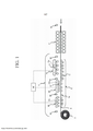
[00029] figura 1 é um diagrama que ilustra esquematicamente uma configuração de um laminador de laminação de acabamento e posteriormente uma instalação de laminação a quente que tem um dispositivo de resfriamento de acordo com uma modalidade.[00029] Figure 1 is a diagram schematically illustrating a configuration of a finishing lamination mill and subsequently a hot rolling installation that has a cooling device according to a modality.
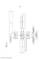
[00030] figura 2 é um diagrama que ilustra esquematicamente um fluxo para determinar as condições de resfriamento. Em que (1) significa “TEMPERATURA ALVO NO LADO DE ENTRADA NA SEÇÃO DE RESFRIAMENTO 20”; em que (2) significa “TEMPERATURA ALVO NO LADO DE SAÍDA NA SEÇÃO DE RESFRIAMENTO 20”; em que (3) significa “TEMPERATURA DE BOBINAMENTO ALVO”; em que (A) significa “CONDIÇÃO DE ROLAGEM DE ACABAMENTO (ESPESSURA DE TIRA DE AÇO, TEMPERATURA ALVO NO LADO DE SAÍDA DO LAMINADOR DE ROLAGEM DE ACABAMENTO, E SIMILARES)”; em que (B) significa no “VALOR DE PROPRIEDADE DE TIRA DE AÇO”; em que (C) significa “PROPRIEDADES DE RESFRIAMENTO DE TIRA DE AÇO (CONDUTIVIDADE TÉRMICA).[00030] Figure 2 is a diagram schematically illustrating a flow to determine cooling conditions. Where (1) means “TARGET TEMPERATURE ON THE INLET SIDE OF
[00031] figura 3 é uma vista esquemática que ilustra um exemplo de uma programação de mudança de velocidade de transporte.[00031] Figure 3 is a schematic view illustrating an example of a transport speed change schedule.
[00032] figura 4 é uma vista esquemática de um histórico de temperatura durante um processo de resfriamento.[00032] Figure 4 is a schematic view of a temperature history during a cooling process.
[00033] figura 5 é uma vista esquemática de um histórico de temperatura durante o processo de resfriamento.[00033] Figure 5 is a schematic view of a temperature history during the cooling process.
[00034] figura 6 é uma vista esquemática que ilustra um modo de resfriamento de uma tira de aço.[00034] Figure 6 is a schematic view illustrating a mode of cooling a steel strip.
[00035] figura 7 é um diagrama que ilustra uma programação de mudança de velocidade de transporte utilizada em um exemplo.[00035] Figure 7 is a diagram illustrating a transport speed change schedule used in an example.
[00036] Os presentes inventores descobriram que, no momento quando uma tira de aço laminada a quente que passou através de uma laminação de acabamento é resfriada através de uma primeira etapa de resfriamento e uma segunda etapa de resfriamento, a qual é uma etapa de um resfriamento rápido, em um processo de laminação a quente no qual uma velocidade de transporte varia, é possível suprimir o desvio de temperaturas de bobinamento da tira de aço controlando o suprimento de água na primeira etapa de resfriamento de modo a tornar as condições de resfriamento tais como o comprimento de resfriamento e a densidade quantidade de água inalteradas tanto quanto possível na segunda etapa de resfriamento independentemente de mudanças na velocidade de transporte, mesmo quando a velocidade de transporte da tira de aço laminada a quente varia. Mais especificamente, os presentes inventores descobriram que é possível suprimir o desvio de temperatura de bobinamento da tira de aço controlando as condições de resfriamento na primeira etapa de modo a satisfazer: 0,8 < (T2a' - T2a)/ΔTx < 1,2 (Equação 1),[00036] The present inventors have found that, at the time when a hot rolled steel strip that has passed through a finishing roll is cooled through a first cooling step and a second cooling step, which is one step of a rapid cooling, in a hot rolling process in which a transport speed varies, it is possible to suppress the deviation of steel strip winding temperatures by controlling the water supply in the first cooling step so as to make the cooling conditions such as the cooling length and density amount of water unchanged as much as possible in the second cooling step regardless of changes in conveying speed, even when the conveying speed of the hot rolled steel strip varies. More specifically, the present inventors have found that it is possible to suppress the steel strip winding temperature drift by controlling the cooling conditions in the first step so as to satisfy: 0.8 < (T2a' - T2a)/ΔTx < 1.2 (Equation 1),
[00037] onde T2a é uma temperatura alvo da tira de aço laminada a quente no lado de entrada em uma segunda seção de resfriamento antes da velocidade de transporte variar; T2a' é uma temperatura alvo da tira de aço laminada a quente no lado de entrada da segunda seção de resfriamento após a velocidade de transporte variar; e ΔTx é a quantidade de mudança na quantidade de resfriamento da tira de aço laminada a quente na segunda seção de resfriamento, a mudança sendo devida à ocorrência da mudança em velocidade de laminação.[00037] where T2a is a target temperature of the hot rolled steel strip on the inlet side in a second cooling section before the conveying speed varies; T2a' is a target temperature of the hot rolled steel strip on the inlet side of the second cooling section after the conveying speed varies; and ΔTx is the amount of change in the amount of hot rolled steel strip cooling in the second cooling section, the change being due to the occurrence of the change in rolling speed.
[00038] Aqui abaixo, com referência aos desenhos, uma descrição será feita de um dispositivo de resfriamento 1 e um método para resfriar uma tira de aço S de acordo com uma modalidade da presente invenção com base nas descobertas acima descritas.[00038] Here below, with reference to the drawings, a description will be made of a
[00039] A figura 1 ilustra esquematicamente uma configuração de um laminador de laminação de acabamento 2 e posteriormente uma instalação de laminação a quente que tem o dispositivo de resfriamento 1 de acordo com esta modalidade.[00039] Figure 1 schematically illustrates a configuration of a finishing
[00040] Como ilustrado na figura 1, a instalação de laminação a quente inclui o laminador de laminação de acabamento 2, um dispositivo de resfriamento 1, e um bobinador 3, os quais estão dispostos nesta ordem na direção de transporte da tira de aço S. O laminador de laminação de acabamento 2 rola continuamente a tira de aço S que foi descarregada de um forno de aquecimento (não mostrado) e foi laminada por um laminador de laminação bruta (não mostrado) com a la- minação contínua sendo acelerada ou desacelerada de acordo com a programação de mudança de velocidade de transporte. O dispositivo de resfriamento 1 resfria a tira de aço S após uma laminação de acabamento para uma temperatura de bobinamento predeterminada da tira de aço de, por exemplo, 300°C. O bobinador 3 bobina a tira de aço S resfriada. Um termômetro 51 para medir uma temperatura de lami- nação de acabamento T0 da tira de aço está provido no lado a montante do laminador de laminação de acabamento 2, e uma mesa de saída 4 formada por rolos de mesa 4a está provida entre o laminador de laminação de acabamento 2 e o bobinador 3. A tira de aço S que foi laminada pelo laminador de laminação de acabamento 2 é resfriada pelo dispositivo de resfriamento 1 enquanto sendo transportada sobre a mesa de saída 4, e então, é bobinada pelo bobinador 3.[00040] As illustrated in figure 1, the hot rolling installation includes the
[00041] Uma primeira unidade de resfriamento 10a que resfria, em uma primeira seção de resfriamento 10, a tira de aço S imediatamente após passar através do laminador de laminação de acabamento 2 está provida no lado a montante no dispositivo de resfriamento 1, em outras palavras, em uma posição imediatamente a jusante do laminador de laminação de acabamento 2. Como ilustrado na figura 1, a primeira unidade de resfriamento 10a está provida com bocais laminares 11 plurais que pulverizam a água de resfriamento, por exemplo, por sobre uma superfície da tira de aço S, os bocais laminares sendo dispostos na direção de largura e na direção de transporte da tira de aço S. A densidade de quantidade de água da água de resfriamento pulverizada dos bocais laminares 11 por sobre a superfície da tira de aço S é ajustada, por exemplo, para 0,3 m3/m2/min. A primeira seção de resfriamento 10 refere a uma seção na qual a tira de aço S é resfriada sob um estado de ebulição de filme pela primeira unidade de resfriamento 10a. Além de pulverizar a água de resfriamento através dos bocais laminares, o resfriamento na primeira seção de resfriamento 10 pode ser executado, por exemplo, pulverizando a água de resfriamento por um bocal de pulverização, por resfriamento a gás utilizando um bocal de ar, por uma combinação de gás e água utilizando um bocal de gás - água (resfriamento de névoa), ou por resfriamento a ar no qual nenhum meio de resfriamento é suprido. Note que o "resfriada sob um estado de ebulição de filme" inclui um estado de resfriamento onde o resfriamento na faixa de ebulição de filme é executado em uma parte da primeira seção de resfriamento enquanto um resfriamento a ar é executado no restante da seção, além de um estado onde o resfriamento sob o estado de ebulição de filme é executado na primeira seção de resfriamento inteira.[00041] A
[00042] Como ilustrado na figura 1, no lado a jusante da primeira unidade de resfriamento 10a, está provida uma segunda unidade de resfriamento 20a que resfria rapidamente, na segunda seção de resfriamento 20 (seção de resfriamento rápido), a tira de aço S que foi resfriada na primeira seção de resfriamento 10. A segunda seção de resfriamento 20 refere a uma seção na qual a segunda unidade de resfriamento 20a resfria a tira de aço S. O termo "resfria rapidamente" como utilizado nesta modalidade refere a um processo de resfriamento no qual a densidade de quantidade de água de resfriamento é ajustada em pelo menos 2 m3/min/m2 ou mais, desejavelmente a 3 m3/min/m2 ou mais. O termo "densidade de quantidade de água de resfriamento" significa a quantidade de água de resfriamento suprida por unidade de 1 m2 sobre a superfície alvo da tira de aço, e no caso de resfriar somente a superfície superior da tira de aço, significa a quantidade de água de resfriamento suprida por unidade de 1 m2 sobre a superfície superior da tira de aço. A segunda unidade de resfriamento 20a está provida, por exemplo, com bocais de pulverização 21 que pulverizam a água de resfriamento por sobre a superfície superior da tira de aço S enquanto sendo disposta na direção de transporte e na direção de largura da tira de aço, e tem uma capacidade de prover a densidade de quantidade de água de resfriamento, por exemplo, de 2 m3/min/m2, desejavelmente 3 m3/m2/min ou mais para a tira de aço S. Com relação ao modo de resfriamento inteiro nesta segunda seção de resfriamento, a segunda unidade de resfriamento 20a tem uma capacidade de resfriar 80% ou mais da duração de resfriamento na segunda seção de resfriamento sob a ebulição de nucleado.[00042] As illustrated in figure 1, on the downstream side of the
[00043] Como ilustrado na figura 3, uma terceira unidade de resfriamento 30a que resfria uma terceira seção de resfriamento 30 pode estar provida no lado a jusante da segunda unidade de resfriamento 20a. Similar à primeira unidade de resfriamento 10a, a terceira unidade de resfriamento 30a está provida com bocais laminares 11 plurais que pulverizam a água de resfriamento por sobre a superfície da tira de aço S enquanto sendo disposta na direção de largura e na direção de transporte da tira de aço S. A densidade de quantidade de água da água de resfriamento pulverizada dos bocais laminares 11 por sobre a superfície da tira de aço S é ajustada, por exemplo, para 0,3 m3/m2/min. Além de pulverizar a água de resfriamento através dos bocais laminares, o resfriamento na terceira seção de resfriamento 30 pode ser executado, por exemplo, pulverizando a água de resfriamento por um bocal de pulverização, por resfriamento a gás utilizando um bocal de ar, por uma combinação de gás e água utilizando um bocal de gás - água (resfriamento de névoa), ou por resfriamento a ar no qual nenhum meio de resfriamento é suprido.[00043] As illustrated in figure 3, a
[00044] Os termômetros 52, 53 para medir uma temperatura de tira de aço no lado de entrada e uma temperatura de tira de aço no lado de saída estão providos no lado de entrada e no lado de saída da primeira seção de resfriamento 10, respectivamente. Ainda, um termômetro 54 para medir uma temperatura de tira de aço do lado de saída está provido no lado de saída da segunda seção de resfriamento 20. Um termômetro 55 para medir uma temperatura de bobinamento da tira de aço está provido no lado a montante do bobinador 3. As temperaturas da tira de aço no momento de resfriamento da tira de aço são medidas em uma base conforme necessário, um controle de alimentação direta e um controle de retorno são executados na primeira seção de resfriamento 10 e na terceira seção de resfriamento 30 com base nos valo-res medidos dos termômetros.[00044]
[00045] A seguir, com referência à figura 2 até a figura 6, uma descrição será feita de um método para resfriar a tira de aço laminada a quente S de acordo com esta modalidade, o método pelo menos incluindo uma primeira etapa de resfriamento, uma segunda etapa de resfriamento, e uma etapa de bobinamento. Note que a descrição será feita na suposição que a terceira unidade de resfriamento 30a está provida.[00045] In the following, with reference to figure 2 to figure 6, a description will be made of a method for cooling the hot rolled steel strip S according to this modality, the method at least including a first cooling step, a second cooling step, and a winding step. Note that the description will be made on the assumption that the
[00046] A figura 2 ilustra um fluxo para determinar as condições de resfriamento na segunda seção de resfriamento 20 no momento de iniciar o resfriamento a tira de aço laminada a quente.[00046] Figure 2 illustrates a flow to determine the cooling conditions in the
[00047] A tira de aço após o completamento de laminação bruta é transportada para o laminador de laminação de acabamento 2, e as suas temperaturas de tira de aço de laminação de acabamento são medidas pelo termômetro 51. Os dados das temperaturas medidas são inseridas em uma unidade de computação 101 com base nas temperaturas da tira de aço e uma condição de laminação de acabamento predeterminada tal como a espessura, a qual foi inserida com antecedência a unidade de computação 101 obtém uma programação de mudança de velocidade de transporte (a velocidade no lado de saída do laminador de laminação de acabamento) em posições na direção longitudinal da tira de aço em um modo que a programação de mudança de velocidade de transporte satisfaça a condição de laminação de acabamento predeterminada, como ilustrado na figura 3. A programação de mudança de velocidade de transporte pode ser obtida de modo a ser associada com as posições na direção longitudinal da tira de aço, além de com o tempo do início da laminação de acabamento.[00047] The steel strip after completion of rough rolling is transported to the
[00048] A programação de mudança de velocidade de transporte obtida pela unidade de computação 101 é enviada para uma unidade de computação 102. A unidade de computação 102 ajusta, por exemplo, as condições de resfriamento tais como a densidade de quantidade de água de resfriamento e o comprimento de resfriamento na segunda seção de resfriamento 20, e uma condição de resfriamento inicial na primeira seção de resfriamento 10, as quais são necessárias para ajustar as respectivas temperaturas da tira de aço de modo a cair dentro da faixa alvo, com base na programação de mudança de velocidade de transporte, uma temperatura de bobinamento alvo T4 da tira de aço, a qual foi inserida com antecedência, a temperatura de tira de aço alvo do lado de entrada T2a e a temperatura de tira de aço alvo do lado de saída T2b na segunda seção de resfriamento 20 e similares. Como a capacidade de resfriamento (velocidade de resfriamento) pode ser expressa como uma função de densidade de quantidade de água,é possível ajustar a densidade é possível ajustar a densidade de quantidade de água necessária e o comprimento de resfriamento obtendo o tempo requerido para passar através da seção de resfriamento com base na programação de mudança de velocidade de transporte. Certos tipos de aço são desejáveis serem resfriados em uma velocidade de resfriamento predeterminada para o propósito de aperfeiçoar as propriedades do aço. Para tais aços, o comprimento de resfriamento necessário pode ser obtido com base na densidade de quantidade de água requerida para a velocidade de resfriamento necessária e a programação de mudança de velocidade de transporte. Em um modo similar, é possível ajustar as condições de resfriamento iniciais na primeira seção de resfriamento 10 e na terceira seção de resfriamento 30 com base na temperatura de bobinamento alvo T4 da tira de aço, a temperatura de tira de aço alvo T2b no lado de saída da segunda seção de resfriamento, a temperatura de aço alvo T2a no lado de entrada da segunda seção de resfriamento e a temperatura de tira de aço alvo T0a no lado de saída da laminação de acabamento.[00048] The transport speed change schedule obtained by the
[00049] No processo de resfriamento contínuo na primeira seção de resfriamento 10 e na terceira seção de resfriamento 30, as condições de resfriamento tais como a densidade de quantidade de água e o comprimento de resfriamento são mudadas controlando o suprimento de água de modo a estar associado com a mudança na velocidade de transporte. Mais especificamente, ajustando a temperatura alvo T2a' da tira de aço no lado de entrada na segunda seção de resfriamento no tempo quando a velocidade de transporte atinge a segunda veloci- dade transporte em um modo que satisfaça a Equação 1 acima descrita, o suprimento de água é controlado na primeira seção de resfriamento de modo a ser capaz de conseguir este valor de ajuste da temperatura de tira de aço alvo durante o processo que transiciona da primeira velocidade de transporte para a segunda velocidade de transporte. Por exemplo, na figura 3, é assumido que a velocidade de transporte no tempo B é ajustada para a primeira velocidade de transporte, e a velocidade de transporte no tempo C é ajustada para a se-gunda velocidade de transporte. Por exemplo, no caso onde a temperatura de bobinamento alvo T4 da tira de aço é de 450°C, a temperatura alvo T2b da tira de aço no lado de saída na segunda seção de resfriamento 20 é ajustada para 480°C, e a temperatura alvo T2a da tira de aço no lado de entrada na segunda seção de resfriamento 20 é ajustada para 600°C como as condições de resfriamento na primeira velocidade de transporte. No momento de ajustar a T2a e a T2b, as capacidades de resfriamento na primeira seção de resfriamento 10, na segunda seção de resfriamento 20 e na terceira seção de resfriamento 30, a temperatura de partida da faixa de ebulição de transição da tira de aço e similares são levadas em consideração. Dos valores de ajuste acima descritos, a quantidade de resfriamento da tira de aço na segunda seção de resfriamento 20 na primeira velocidade de transporte é T2a - T2b = 120°C, e as condições de resfriamento tais como o comprimento de resfriamento e a densidade de quantidade de água na segunda seção de resfriamento são determinadas de modo a ser capaz de atingir a equação.[00049] In the continuous cooling process in the
[00050] Durante um processo de resfriamento contínuo no qual a velocidade de transporte transiciona para a segunda velocidade de transporte, a velocidade de transporte muda com o avanço da lamina- ção de acabamento, como ilustrado na figura 3. Por outro lado, a quantidade Tx de resfriamento na segunda seção de resfriamento 20 (em outras palavras, T2ax - T2bx) varia como ilustrado na figura 5 no caso onde T2ax e as condições de resfriamento na segunda seção de resfriamento (comprimento de resfriamento e a densidade de quantidade de água de resfriamento) permanecem inalteradas, e uma diferença da quantidade de resfriamento pode ser expressa como ΔTx (em outras palavras, Tx2 - Tx1) durante a transição para a segunda velocidade de transporte. Portanto, no momento de transicionar da primeira velocidade de transporte para a segunda velocidade de transporte, é necessário ajustar a temperatura alvo da tira de aço no lado de entrada na segunda seção de resfriamento e executar um ajuste controlando a água suprida na primeira seção de resfriamento, levando em consideração a quantidade de mudança em Tx. O ajuste acima descrito é feito em consideração à precisão de controle na seção de resfriamento 1 na faixa que cai dentro de 0,8 < (T2a' - T2a)/ΔTx < 1,2, desejavelmente, 0,9 < (T2a' - T2a)/ΔTx < 1,1, onde T2a é a temperatura alvo da tira de aço no lado de entrada na segunda seção de resfriamento na primeira velocidade de transporte, e T2a' é a temperatura alvo da tira de aço no lado de entrada da segunda seção de resfriamento após a velocidade de transporte tornar-se a segunda velocidade de transporte. A temperatura alvo T2a" da tira de aço no lado de entrada na segunda seção de resfriamento durante a transição da primeira velocidade de transporte para a segunda velocidade de transporte pode ser expressa como uma função de tempo com base na T2a e na T2a'. Por exemplo, a função pode ser dada como valores associados com o tempo, utilizando o tempo requerido para transicionar da primeira velocidade de transporte para a segunda velocidade de transporte, e a quantidade média de mudança em temperaturas por tempo unitário ((T2a' - T2a)/t). Ainda, na figura 3, no caso onde a primeira velocidade de transporte é uma velocidade de transporte no tempo A e a segunda velocidade de transporte é uma velocidade de transporte no tempo B, a velocidade de transporte é constante durante a transição do tempo A para o tempo B, e com isto, ΔTx é zero nesta transição. Portanto, T2a = T2a' é estabelecido durante a transição do tempo A para o tempo B. O suprimento da água é controlado pela seção de resfriamento 1 de modo a ser o ajuste T2a', e a tira de aço é resfriada na segunda seção de resfriamento em um estado onde as condições de resfriamento tais como o comprimento de resfriamento e/ou a densidade de quantidade de água são substancialmente constantes. Note que a frase "substancialmente constante" significa que a quantidade de mudança no comprimento de resfriamento cai dentro da faixa de 90% a 110%, e a quantidade de mudança na densidade de quantidade de água cai dentro da faixa de 80% a 120%. Ainda, em um modo similar, no caso onde a programação de velocidade de transporte é obtida com relação à direção longitudinal da tira de aço, é possível ajustar uma nova temperatura de tira de aço alvo T2a' de modo a ser associada com as posições na direção longitudinal da tira de aço.[00050] During a continuous cooling process in which the transport speed transitions to the second transport speed, the transport speed changes with the advancement of the finishing mill, as illustrated in figure 3. On the other hand, the quantity Cooling Tx in the second cooling section 20 (in other words T2ax - T2bx) varies as illustrated in figure 5 in the case where T2ax and the cooling conditions in the second cooling section (cooling length and water quantity density of cooling) remain unchanged, and a difference in the amount of cooling can be expressed as ΔTx (in other words, Tx2 - Tx1) during the transition to the second transport speed. Therefore, when transitioning from the first transport speed to the second transport speed, it is necessary to adjust the target temperature of the steel strip on the inlet side in the second cooling section and perform an adjustment controlling the water supplied in the first cooling section , taking into account the amount of change in Tx. The adjustment described above is made in consideration of the control accuracy in
[00051] Como o resfriamento na faixa de ebulição de filme é executado na primeira seção de resfriamento 10, é possível atingir precisamente a temperatura da tira de aço no lado de saída na segunda seção de resfriamento controlando o suprimento da água de acordo com a mudança na velocidade de transporte, e tornar o comprimento de resfriamento e a densidade de quantidade de água de resfriamento da segunda unidade de resfriamento 20a quase inalterados na segunda seção de resfriamento 20. Isto torna possível: remover a perturbação de resfriamento externo causada pela entrada da água que existe sobre a tira de aço resultando do LIGAMENTO/DESLIGAMENTO da válvula de suprimento de água; suprimir o desvio da temperatura da tira de aço no lado de saída na segunda seção de resfriamento; e atingir precisamente a temperatura de bobinamento da tira de aço.[00051] As cooling in the film boiling range is performed in the
[00052] A faixa de temperatura na qual as condições de resfriamen- to são constante na segunda seção de resfriamento pode ser ajustada na faixa de 300°C a 700°C, e mais desejavelmente, na faixa de 400°C a 600°C. Isto é porque é possível reduzir adicionalmente o desvio da temperatura de bobinamento da tira de aço reduzindo o tempo requerido para resfriar sob a ebulição de transição na segunda seção de resfriamento. Como ilustrado na figura 6, no caso onde a densidade de quantidade de água na segunda seção de resfriamento 20 é 3 m3/min/m2 e a densidade de quantidade de água na primeira seção de resfriamento 10 é 0,3 m3/m2/min, o resfriamento sob a ebulição de transição (B) inicia em temperaturas de tira de aço de aproximadamente 700°C e aproximadamente 600°C, respectivamente, e o resfriamento sob a ebulição de filme (A) é executado na faixa das temperaturas de tira de aço mais alta do que estas temperaturas. Com o resfriamento sob a ebulição de filme, é possível obter uma capacidade de resfri-amento estável (coeficiente de transferência de calor), independentemente das temperaturas de tira de aço. Por outro lado, com o resfriamento sob a ebulição de transição, o desvio das temperaturas da tira de aço aumenta, porque a capacidade de resfriamento aumenta abruptamente devido a uma diminuição na temperatura de tira de aço, o que acelera adicionalmente o resfriamento nas porções de temperatu-ra mais baixa.[00052] The temperature range in which the cooling conditions are constant in the second cooling section can be set in the range of 300°C to 700°C, and more desirably, in the range of 400°C to 600°C . This is because it is possible to further reduce the steel strip winding temperature drift by reducing the time required to cool under transition boiling in the second cooling section. As illustrated in figure 6, in the case where the water quantity density in the
[00053] Portanto, resfriando, na primeira seção de resfriamento 10, a tira de aço para a temperatura mais baixa (600°C) na qual o resfriamento é executado sob a ebulição de filme e então, executando o resfriamento rápido na segunda seção de resfriamento 20, é possível reduzir o tempo requerido para resfriamento sob a ebulição de transição na segunda seção de resfriamento, por meio de que é possível reduzir a variação em resfriamento causada pela execução do resfriamento sob o estado de ebulição de transição. Com este processo, é possível obter estavelmente a temperatura de tira de aço no lado de saída na segunda seção de resfriamento, por meio de que é possível reduzir adicionalmente o desvio da temperatura de resfriamento da tira de aço.[00053] Therefore, by cooling, in the
[00054] O modo de resfriamento da tira de aço ilustrado na figura 6 será descrito em mais detalhes. No caso onde a temperatura da tira de aço é mais alta do que 700°C e o resfriamento rápido é executado com a densidade de quantidade de água de 3 m3/min/m2, o resfriamento da tira de aço é executado sob a ebulição de filme (A) sob a qual a capacidade de resfriamento da tira de aço (coeficiente de transferência de calor) é pequena. Portanto, o fluxo da água de resfriamento sobre a tira de aço e a mudança no comprimento de resfriamento, o que não segue a mudança na velocidade de transporte, têm um pequeno impacto sobre o desvio da temperatura de bobinamento da tira de aço. Ainda, um resfriamento rápido na faixa de temperatura mais baixa do que 300°C não provê efeitos suficientes se a quantidade de investimento nas instalações for comparada com o efeito assim obtido em termos de proprieda-des de material. Em geral, o resfriamento rápido da tira de aço na faixa de temperatura de 300°C a 700°C provê uma vantagem em obter propriedades de material predeterminadas. No entanto, nesta faixa de temperatura, a tira de aço é resfriada sob a ebulição de transição (B) e a ebulição de nucleado (C). Na ebulição de transição, a capacidade de resfriamento da tira de aço aumenta abruptamente com a diminuição na temperatura de tira de aço, enquanto que o resfriamento sob o estado de ebulição de nucleado provê uma capacidade de resfriamento cinco até quase 10 vezes maior do que aquela obtida no estado de ebulição de filme quando executado pela mesma quantidade de água. Mais especificamente, o fluxo da água de resfriamento sobre a tira de aço, e a mudança no comprimento de resfriamento, o que não segue a mudança na velocidade de transporte, têm um grande impacto sobre a uniformidade das temperaturas de bobinamento da tira de aço, e com isto, é importante impedir a ocorrência do fluxo da água de resfriamento sobre a tira de aço e a mudança no comprimento de resfriamento nesta faixa de temperatura de modo a aperfeiçoar a uniformidade das temperaturas de bobinamento da tira de aço.[00054] The steel strip cooling mode illustrated in figure 6 will be described in more detail. In the case where the temperature of the steel strip is higher than 700°C and the blast chilling is performed with the water quantity density of 3 m3/min/m2, the cooling of the steel strip is performed under the boiling of film (A) under which the cooling capacity of the steel strip (heat transfer coefficient) is small. Therefore, the flow of cooling water over the steel strip and the change in the cooling length, which does not follow the change in transport speed, has a small impact on the deviation of the steel strip winding temperature. Furthermore, rapid cooling in the temperature range lower than 300°C does not provide sufficient effects if the amount of investment in the facility is compared with the effect thus obtained in terms of material properties. In general, the rapid cooling of the steel strip in the temperature range of 300°C to 700°C provides an advantage in obtaining predetermined material properties. However, in this temperature range, the steel strip is cooled under transition boiling (B) and nucleate boiling (C). In transition boiling, the cooling capacity of the steel strip increases abruptly with decreasing steel strip temperature, while cooling under the nucleate boiling state provides a cooling capacity five to almost 10 times greater than that. obtained in the boiling state of film when run by the same amount of water. More specifically, the flow of cooling water over the steel strip, and the change in cooling length, which does not follow the change in transport speed, has a great impact on the uniformity of steel strip winding temperatures, and with this, it is important to prevent the cooling water flow from occurring over the steel strip and the change in the cooling length in this temperature range in order to improve the uniformity of the steel strip winding temperatures.
[00055] No momento quando as condições de resfriamento na segunda seção de resfriamento 20 são determinadas, é possível determinar o comprimento de resfriamento com base no valor máximo da velocidade de transporte na programação de mudança de velocidade de transporte, e ajustar o valor inicial da temperatura alvo T2a da tira de aço no lado de entrada na segunda seção de resfriamento com base no valor mínimo da velocidade de transporte na programação de mudança de velocidade de transporte. Um seu exemplo inclui um caso onde a temperatura da tira de aço no lado de entrada na segunda se-ção de resfriamento 20 no resfriamento contínuo é desejada ser um certo valor ou mais.[00055] At the time when the cooling conditions in the
[00056] A seguir, uma descrição será feita de um método para ajustar as condições de resfriamento iniciais na segunda seção de resfriamento 20 determinando o comprimento de resfriamento com base no valor máximo da velocidade de transporte na programação de velocidade de transporte, e ajustar um valor inicial da temperatura alvo T2a da tira de aço no lado de entrada na segunda seção de resfriamento com base no valor mínimo da velocidade de transporte. Na figura 3, a velocidade de transporte aumenta e diminui em uma linha aproximadamente reta acelerando e desacelerando da extremidade dianteira para a extremidade traseira da tira de aço. Na figura 3, o valor mínimo da velocidade de transporte é denotado por V(min), o valor máximo é denotado por V(max), e a velocidade no final da laminação de acabamento é denotada por V(fin).[00056] In the following, a description will be made of a method to adjust the initial cooling conditions in the
[00057] Como acima descrito, por exemplo, a quantidade de resfriamento na segunda seção de resfriamento 20 é T2a - T2b = 120°C no caso onde a temperatura de resfriamento alvo T4 da tira de aço é ajus- tada para 450°C, a temperatura alvo T2b da tira de aço no lado de saída da segunda seção de resfriamento 20 é ajustada para 480°C, e a temperatura alvo T2a da tira de aço no lado de entrada na segunda seção de resfriamento 20 é ajustada para 600°C. Para a velocidade de transporte da tira de aço, V(min) é 400 m/min, V(max) é 600 m/min e V(fin) é 520 m/min, por exemplo. Como os ajustes iniciais das condições de resfriamento na segunda seção de resfriamento 20 sob a qual o resfriamento de 120°C pode ser atingido no tempo quando a tira de aço é transportada a 600 m/min, a quantidade de água de resfriamento é ajustada, por exemplo, para 3 m3/min/m2, e o comprimento de resfriamento é ajustado para 3 m.[00057] As described above, for example, the amount of cooling in the
[00058] No caso onde o resfriamento é executado sob as condições de resfriamento acima descritas, o tempo requerido para o resfriamento é 1,5 vezes mais longo do que o tempo da velocidade de transporte sendo 400 m/min, a qual é o valor mínimo. Portanto, a quantidade de resfriamento aumenta por aproximadamente 60°C, de modo que a quantidade de resfriamento na segunda seção de resfriamento 20 é de aproximadamente 180°C. Como é desejável ajustar a temperatura T2b da tira de aço no lado de saída na segunda seção de resfriamento 20 para ser constante, o ajuste inicial da temperatura alvo T2a da tira de aço no lado de entrada na segunda seção de resfriamento 20 é ajustado para 660°C, o que é 60°C mais alto do que 600°C.[00058] In the case where the cooling is performed under the cooling conditions described above, the time required for cooling is 1.5 times longer than the transport speed time being 400 m/min, which is the value Minimum. Therefore, the amount of cooling increases by approximately 60°C, so the amount of cooling in the
[00059] Na seção de aceleração, a quantidade de resfriamento T2a - T2b na segunda seção de resfriamento 20 diminui, e com isto, em resposta à aceleração, a temperatura alvo T2a' da tira de aço no lado de entrada na segunda seção de resfriamento é tornada diminuída da temperatura de 600°C de acordo com a mudança na velocidade de transporte. Então, no momento quando a velocidade de transporte atinge a velocidade máxima, a temperatura alvo T2a' da tira de aço no lado de entrada na segunda seção de resfriamento 20 é de 600°C.[00059] In the acceleration section, the amount of cooling T2a - T2b in the
[00060] Quando a laminação de acabamento avança adicionalmente e entra na seção de desaceleração, a quantidade de resfriamento T2a - T2b na segunda seção de resfriamento 20 aumenta, e assim, a temperatura alvo T2a da tira de aço no lado de entrada na segunda seção de resfriamento é tornada aumentada novamente de 600°C. Como a velocidade V(fin) no final da laminação é V(min) < V(fin) < V(max), a relação no lado de entrada da segunda seção de resfriamento 20 entre a temperatura de tira de aço alvo T2a(Vmax) na velocidade máxima, a temperatura de tira de aço alvo T2a(Vmin) na velocidade mínima e a temperatura de tira de aço alvo T2a(Vfin) no final da lami- nação é T2a(Vmax) < T2a(Vfin) < T2a(Vmin).[00060] When the finishing mill advances further and enters the deceleration section, the amount of quench T2a - T2b in the second quench
[00061] Como acima descrito, as condições de resfriamento na segunda seção de resfriamento 20 são ajustadas de modo que o comprimento de resfriamento seja determinado com base no valor máximo da velocidade de transporta, e o valor inicial da temperatura alvo T2a da tira de aço no lado de entrada na segunda seção de resfriamento é ajustado com base no valor mínimo da velocidade de transporte. Com este ajuste, a temperatura alvo T2a da tira de aço no lado de entrada na segunda seção de resfriamento pode ser tornada sempre mais alta do que a T2a(ini), o qual é o valor de ajuste inicial, no processo de resfriamento contínuo no qual a velocidade de transporte varia. No caso onde o resfriamento da segunda seção de resfriamento é iniciado de uma temperatura na vizinhança da temperatura na qual o resfriamento sob a ebulição de transição na primeira seção de resfriamento 10 é iniciada, é possível evitar o resfriamento sob a ebulição de transição na primeira seção de resfriamento 10.[00061] As described above, the cooling conditions in the
[00062] Na segunda seção de resfriamento 20, o resfriamento é executado com o comprimento de resfriamento e/ou a densidade de quantidade de água sendo constantes independentemente da velocidade de transporte; na primeira seção de resfriamento 10 e na terceira seção de resfriamento 30, o suprimento de água é controlado com base na velocidade de transporte abrindo e fechando a válvula, para resfriar a tira de aço de modo a ser uma temperatura de bobinamento predeterminada da tira de aço; e então, a tira de aço é bobinada pelo bobinador.[00062] In the
[00063] Para controlar o suprimento de água na primeira seção de resfriamento 10 e na terceira seção de resfriamento 30, é desejável que os termômetros sejam providos no lado de entrada e no lado de saída da segunda seção de resfriamento 20, e que o controle de retorno e o controle de alimentação direta sejam executados utilizando os valores dos termômetros. Utilizando as temperaturas de tira de aço realmente medidas no controle, é possível atingir precisamente a temperatura alvo T2a da tira de aço no lado de entrada na segunda seção de resfriamento, e a temperatura de bobinamento da tira de aço.[00063] To control the water supply in the
[00064] No momento de determinar as condições de resfriamento na segunda seção de resfriamento, pode ser possível determinar a densidade de quantidade de água de resfriamento com antecedência, e então, obter o comprimento de resfriamento de modo que a quantidade requerida de resfriamento T2a - T2b possa ser atingida. Por exemplo, pode ser possível designar com antecedência certos tipos de aços como aços a serem resfriados com a densidade de quantidade de água de resfriamento de 3 m3/min/m2, e então, determinar o comprimento de resfriamento.[00064] When determining the cooling conditions in the second cooling section, it may be possible to determine the cooling water quantity density in advance, and then obtain the cooling length so that the required amount of cooling T2a - T2b can be achieved. For example, it may be possible to designate in advance certain types of steels as steels to be cooled with the cooling water quantity density of 3 m3/min/m2, and then determine the cooling length.
[00065] Na segunda seção de resfriamento, é possível executar o resfriamento com a quantidade de água de resfriamento e o comprimento de resfriamento com os quais o resfriamento sob a faixa de ebulição de nucleado é responsável por 80% ou mais. Isto torna possível suprimir a variação em temperaturas causada pelo resfriamento sob a ebulição de transição, e resfriar o alvo em um modo uniforme.[00065] In the second cooling section, it is possible to perform the cooling with the amount of cooling water and the cooling length with which cooling under the nucleate boiling range accounts for 80% or more. This makes it possible to suppress the variation in temperatures caused by cooling under transition boiling, and to cool the target in a uniform way.
[00066] A segunda seção de resfriamento pode ser dividida em uma seção de resfriamento dianteira, uma seção de resfriamento média, e uma seção de resfriamento traseira. Neste caso, as temperaturas da tira de aço no lado de saída são medidas no lado de saída da seção de resfriamento dianteira. Com base na temperatura de tira de aço no lado de saída medida na seção de resfriamento dianteira, as condições de resfriamento na seção de resfriamento média são mudadas, e a temperatura do aço no lado de entrada da seção de resfriamento traseira é controlada de modo a cair dentro de uma faixa predeterminada, por meio de que é possível suprimir favoravelmente o desvio da temperatura de bobinamento da tira de aço.[00066] The second cooling section can be divided into a front cooling section, a middle cooling section, and a rear cooling section. In this case, the steel strip temperatures on the outlet side are measured on the outlet side of the front cooling section. Based on the output side steel strip temperature measured in the front cooling section, the cooling conditions in the middle cooling section are changed, and the steel temperature in the inlet side of the rear cooling section is controlled so as to falls within a predetermined range, whereby it is possible to favorably suppress the deviation of the coiling temperature of the steel strip.
[00067] Na terceira seção de resfriamento 30, pode ser possível executar o resfriamento com a densidade de quantidade de água da água de resfriamento na faixa de 0,05 m3/min/m2 a 0,15 m3/min/m2. O resfriamento na terceira seção de resfriamento 30 pode ser executado suprindo a água de resfriamento como o meio de resfriamento, um gás ou uma sua mistura, assim como por resfriamento a ar no qual nenhum meio de resfriamento e suprido. Isto é porque, reduzindo a densidade de quantidade de água, é possível aperfeiçoar a controlabilida- de em resfriamento, por meio de que é possível atingir precisamente a temperatura de bobinamento da tira de aço.[00067] In the
[00068] A seguir, uma descrição será feita de Exemplos A1 a A7, Exemplos B1 a B7, Exemplos C1 a C7, e Exemplos D1 a D7, cada um dos quais emprega o laminador de laminação de acabamento, a primeira unidade de resfriamento, a segunda unidade de resfriamento, e o bobinador.[00068] In the following, a description will be made of Examples A1 to A7, Examples B1 to B7, Examples C1 to C7, and Examples D1 to D7, each of which employs the finish laminating laminator, the first cooling unit, the second cooling unit, and the winder.
[00069] Em cada um dos Exemplos, uma tira de aço laminada a quente foi sujeita à laminação de acabamento de acordo com a programação de mudança de velocidade de transporte ilustrada na figura 7, e então, sujeita ao primeiro resfriamento e ao segundo resfriamento. A Tabela 1 mostra as condições de resfriamento e os resultados de avaliação dos Exemplos. Na figura 7, t = 0 indica um momento quando a porção de extremidade superior da tira de aço laminada a quente atinge a primeira seção de resfriamento, e t = 90 indica um momento quando a porção de extremidade traseira da tira de aço laminada a quente atinge o bobinador. Nos presentes Exemplos, a avaliação foi feita ajustando a primeira velocidade de transporte para ser uma velocidade de transporte em t = 20, e o ajuste da segunda velocidade de transporte para ser uma velocidade de transporte em t = 50. Deve ser notado que a temperatura alvo da tira de aço no lado de saída na se-gunda seção de resfriamento é ajustada para 400°C. TABELA 1
[00070] Na Tabela 1, o "desvio de temperatura de tira de aço no lado de entrada na segunda seção de resfriamento" e o "desvio de temperatura de bobinamento da tira de aço" cada um refere ao desvio de temperaturas obtidas medindo continuamente as temperaturas do centro da largura da tira de aço na direção na qual a tira de aço move.[00070] In Table 1, the "steel strip temperature offset at the inlet side in the second cooling section" and the "steel strip winding temperature offset" each refer to the temperature offset obtained by continuously measuring the temperatures from the center of the steel strip width in the direction in which the steel strip moves.
[00071] Nos presentes Exemplos, como a tira de aço foi resfriada a ar da saída da segunda seção de resfriamento até o bobinamento, o desvio da temperatura de tira de aço no lado de saída da segunda seção de resfriamento é considerado ser quase igual ao desvio da temperatura de bobinamento da tira de aço.[00071] In the present Examples, as the steel strip was air cooled from the outlet of the second cooling section to the winding, the deviation of the steel strip temperature on the outlet side of the second cooling section is considered to be almost equal to deviation of the steel strip winding temperature.
[00072] Os resultados destes exemplos confirmam que o efeito de suprimir o desvio da temperatura de bobinamento da tira de aço pode ser obtido ajustando a temperatura alvo t2a' da tira de aço no lado de entrada na segunda seção de resfriamento de modo que o valor de (T2a'-T2a)/ΔTx caia dentro da faixa de 0,8 a 1,2.[00072] The results of these examples confirm that the effect of suppressing the deviation of the steel strip winding temperature can be obtained by setting the target temperature t2a' of the steel strip on the inlet side in the second cooling section so that the value of (T2a'-T2a)/ΔTx falls within the range of 0.8 to 1.2.
[00073] Mais ainda, os resultados dos Exemplos C1 a C7, os quais são exemplos comparativos, confirmam que, mesmo ajustando a temperatura alvo T2a' da tira de aço no lado de entrada da segunda seção de resfriamento de modo que o valor de (T2a'-T2a)/ΔTx caia dentro da faixa de 0,8 a 1,2, o efeito de suprimir o desvio da temperatura de bo- binamento da tira de aço não pode ser obtido no caso onde a densidade de quantidade de água na segunda seção de resfriamento é menor do que 2,0 m3/min/m2.[00073] Furthermore, the results of Examples C1 to C7, which are comparative examples, confirm that even setting the target temperature T2a' of the steel strip on the inlet side of the second cooling section so that the value of ( T2a'-T2a)/ΔTx falls within the range of 0.8 to 1.2, the effect of suppressing the steel strip winding temperature deviation cannot be obtained in the case where the water quantity density in the second cooling section is less than 2.0 m3/min/m2.
[00074] Como acima descrito, a modalidade preferida da presente invenção foi descrita com referência aos desenhos anexos. No entanto, a presente invenção não está limitada aos exemplos. Aparentemente, a pessoa versada na técnica pode alcançar vários exemplos de mudança ou exemplos de modificação dentro do escopo do princípio técnico Reivindicado. É compreendido que estes exemplos de mudanças ou exemplos de modificações estão naturalmente incluídos no es- copo técnico da presente invenção.[00074] As described above, the preferred embodiment of the present invention has been described with reference to the accompanying drawings. However, the present invention is not limited to examples. Apparently, the person skilled in the art can achieve several examples of change or examples of modification within the scope of the Claimed technical principle. It is understood that these examples of changes or examples of modifications are naturally included within the scope of the present invention.
[00075] De acordo com a presente invenção, é possível resfriar precisamente e uniformemente uma tira de aço laminada a quente transportada de um laminador de laminação de acabamento a uma velocidade de transporte com aceleração de desaceleração, para atingir uma temperatura de bobinamento predeterminada da tira de aço. LISTAGEM DE REFERÊNCIA 1 Dispositivo de resfriamento 2 Laminador de laminação de acabamento 3 Bobinador 4 Mesa de saída 4a Rolo de mesa 10 Primeira seção de resfriamento 10a Primeira unidade de resfriamento 11 Bocal laminar 20 Segunda seção de resfriamento (seção de resfriamento rápido) 20a Segunda unidade de resfriamento (unidade de resfriamento rápido) 21 Bocal de pulverização (sobre o lado de superfície superior) 30 Terceira seção de resfriamento 30a Terceira unidade de resfriamento 40 Unidade de controle 51, 52, 53, 54, 55 Termômetro S Tira de aço V(min) Velocidade de transporte mínima V(max) Velocidade de transporte máxima V(fin) Velocidade de transporte no final da laminação de acaba mento T2a(Vmin) Temperatura alvo da tira de aço no lado de entrada da se-gunda seção de resfriamento na velocidade de transporte mínima T2a(Vmax) Temperatura alvo da tira de aço no lado de entrada da se-gunda seção de resfriamento na velocidade de transporte máxima T2a(Vfin) Temperatura alvo da tira de aço no lado de entrada da segunda seção de resfriamento com relação a uma velocidade de transporte no final da laminação de acabamento (A) Resfriamento sob ebulição de filme (B) Resfriamento sob ebulição de transição (C) Resfriamento sob ebulição de nucleado[00075] According to the present invention, it is possible to precisely and uniformly cool a hot rolled steel strip transported from a finishing rolling mill at a transport speed with deceleration acceleration, to reach a predetermined strip coiling temperature of steel.
Claims (9)
Applications Claiming Priority (3)
| Application Number | Priority Date | Filing Date | Title |
|---|---|---|---|
| JP2009-285121 | 2009-12-16 | ||
| JP2009285121 | 2009-12-16 | ||
| PCT/JP2010/072639 WO2011074632A1 (en) | 2009-12-16 | 2010-12-16 | Method for cooling hot-rolled steel plate |
Publications (2)
| Publication Number | Publication Date |
|---|---|
| BR112012004729A2 BR112012004729A2 (en) | 2016-03-15 |
| BR112012004729B1 true BR112012004729B1 (en) | 2021-07-20 |
Family
ID=44167383
Family Applications (1)
| Application Number | Title | Priority Date | Filing Date |
|---|---|---|---|
| BR112012004729-9A BR112012004729B1 (en) | 2009-12-16 | 2010-12-16 | METHOD FOR COOLING A HOT ROLLED STEEL STRIP |
Country Status (9)
| Country | Link |
|---|---|
| US (1) | US8359894B2 (en) |
| EP (1) | EP2465620B1 (en) |
| JP (1) | JP4938159B2 (en) |
| KR (1) | KR101211273B1 (en) |
| CN (1) | CN102481610B (en) |
| BR (1) | BR112012004729B1 (en) |
| IN (1) | IN2012DN00945A (en) |
| TW (1) | TWI379010B (en) |
| WO (1) | WO2011074632A1 (en) |
Families Citing this family (24)
| Publication number | Priority date | Publication date | Assignee | Title |
|---|---|---|---|---|
| FI20070622L (en) * | 2007-08-17 | 2009-04-15 | Outokumpu Oy | Method and device for checking evenness during cooling of a strip made of stainless steel |
| WO2014087520A1 (en) * | 2012-12-06 | 2014-06-12 | 新日鐵住金株式会社 | Device for cooling hot-rolled steel sheet |
| US9186710B2 (en) | 2011-06-07 | 2015-11-17 | Nippon Steel & Sumitomo Metal Corporation | Method for cooling hot-rolled steel sheet |
| US9566625B2 (en) | 2011-06-07 | 2017-02-14 | Nippon Steel & Sumitomo Metal Corporation | Apparatus for cooling hot-rolled steel sheet |
| US9211574B2 (en) | 2011-07-27 | 2015-12-15 | Nippon Steel & Sumitomo Metal Corporation | Method for manufacturing steel sheet |
| KR101376565B1 (en) * | 2011-12-15 | 2014-04-02 | (주)포스코 | Method and apparatus for controlling the temperature of strip in the rapid cooling section of continuous annealing line |
| JP5741634B2 (en) * | 2013-04-03 | 2015-07-01 | Jfeスチール株式会社 | Method and apparatus for cooling control of hot-rolled steel sheet |
| CN104043660B (en) * | 2013-09-26 | 2015-09-30 | 北大方正集团有限公司 | A kind of production technology of non-hardened and tempered steel |
| CN104001742A (en) * | 2014-05-21 | 2014-08-27 | 中冶南方工程技术有限公司 | Method for achieving controlled cooling on rolled pieces between and after bar finishing mill units |
| EP3156512B1 (en) * | 2014-07-24 | 2022-01-12 | Nippon Steel Corporation | Method for cooling steel strip and cooling installation |
| CN104438356B (en) * | 2014-09-23 | 2017-04-05 | 北京首钢股份有限公司 | A kind of method for improving Thin container plate edge shape wave |
| CN104668295B (en) * | 2015-02-13 | 2017-04-12 | 中冶南方工程技术有限公司 | Control method and control device of rod and wire production line temperature control rolling process |
| EP3061535B1 (en) | 2015-02-27 | 2019-02-27 | Primetals Technologies Austria GmbH | Reel device with asymmetric cooling of the reeled strip |
| JP6245766B2 (en) * | 2015-05-26 | 2017-12-13 | Primetals Technologies Japan株式会社 | Hot-rolled steel plate cooling apparatus and mask member position adjusting method |
| US11560606B2 (en) | 2016-05-10 | 2023-01-24 | United States Steel Corporation | Methods of producing continuously cast hot rolled high strength steel sheet products |
| KR102557715B1 (en) | 2016-05-10 | 2023-07-20 | 유나이테드 스테이츠 스틸 코포레이션 | Annealing process for high-strength steel products and their manufacture |
| WO2018029768A1 (en) * | 2016-08-09 | 2018-02-15 | 東芝三菱電機産業システム株式会社 | Rolling mill exit side temperature control system |
| JP6477919B2 (en) * | 2016-08-22 | 2019-03-06 | Jfeスチール株式会社 | Method for cooling high-temperature metal and method for producing hot-dip galvanized steel strip |
| EP3825019B1 (en) * | 2018-09-19 | 2023-06-14 | Nippon Steel Corporation | Cooling device for hot-rolled steel sheet and cooling method of hot-rolled steel sheet |
| AU2020268370A1 (en) | 2019-05-07 | 2021-12-02 | United States Steel Corporation | Methods of producing continuously cast hot rolled high strength steel sheet products |
| BR112022001335A2 (en) | 2019-08-07 | 2022-03-22 | United States Steel Corp | Quenching and separating steel sheet product, and, method for producing tempering and separating steel sheet product |
| CN114630914A (en) | 2019-08-19 | 2022-06-14 | 美国钢铁公司 | High strength steel product and annealing method for producing the same |
| CN110624960B (en) * | 2019-09-24 | 2021-02-09 | 张家港宏昌钢板有限公司 | Strip steel cooling control method combining ultra-fast cooling and conventional laminar cooling |
| CN114618895B (en) * | 2022-04-11 | 2022-11-08 | 福建三宝特钢有限公司 | Hot rolled strip rolling system based on dynamic adjustment |
Family Cites Families (22)
| Publication number | Priority date | Publication date | Assignee | Title |
|---|---|---|---|---|
| US3604234A (en) | 1969-05-16 | 1971-09-14 | Gen Electric | Temperature control system for mill runout table |
| DE2507641A1 (en) | 1975-02-21 | 1976-09-02 | Sp K Bjuro Uraltschermetwtomat | Hot rolled strip cooling control - varies coolant nozzle group numbers as function of strip velocity and set cooling time |
| JPH01312031A (en) | 1988-06-13 | 1989-12-15 | Kawasaki Steel Corp | Manufacture of hot rolled steel stock |
| JPH03198905A (en) | 1989-12-26 | 1991-08-30 | Sumitomo Metal Ind Ltd | Control method for cooling rolled stock |
| JPH03277721A (en) | 1990-03-28 | 1991-12-09 | Sumitomo Metal Ind Ltd | Method for controlling cooling of hot rolled steel strip |
| JP2744399B2 (en) | 1993-06-18 | 1998-04-28 | 三菱電機株式会社 | Rolled material cooling control device |
| JPH08252625A (en) | 1995-03-16 | 1996-10-01 | Kawasaki Steel Corp | Method for controlling coiling temperature in hot rolling |
| JP3423500B2 (en) | 1995-09-19 | 2003-07-07 | 三菱電機株式会社 | Hot rolled steel sheet winding temperature control apparatus and method |
| JP3058403B2 (en) | 1996-02-08 | 2000-07-04 | 住友金属工業株式会社 | Cooling control method for hot rolled steel sheet |
| JP3514914B2 (en) | 1996-06-20 | 2004-04-05 | 三菱電機株式会社 | Temperature control method of hot rolled steel sheet |
| JP4164982B2 (en) | 2000-03-01 | 2008-10-15 | Jfeスチール株式会社 | Hot-rolled steel strip cooling device and cooling method thereof |
| JP3815410B2 (en) | 2001-08-31 | 2006-08-30 | Jfeスチール株式会社 | Cooling control method for hot-rolled steel strip |
| JP2006518670A (en) * | 2003-02-25 | 2006-08-17 | シーメンス アクチエンゲゼルシヤフト | Method for adjusting the temperature of a metal strip, in particular in a finish rolling section for rolling a heated metal strip |
| JP4529517B2 (en) | 2003-06-27 | 2010-08-25 | Jfeスチール株式会社 | High carbon steel plate manufacturing method and manufacturing equipment |
| JP4525133B2 (en) * | 2004-03-30 | 2010-08-18 | Jfeスチール株式会社 | Manufacturing method of hot-rolled steel strip |
| CN1706568A (en) * | 2004-06-08 | 2005-12-14 | 三菱日立制铁机械株式会社 | High strong hot-rolling steel plate producing equipment |
| JP4119928B2 (en) * | 2006-08-18 | 2008-07-16 | 新日本製鐵株式会社 | Steel plate cooling method |
| JP4238260B2 (en) * | 2006-09-19 | 2009-03-18 | 新日本製鐵株式会社 | Steel plate cooling method |
| JP4449991B2 (en) | 2007-02-26 | 2010-04-14 | Jfeスチール株式会社 | Apparatus and method for cooling hot-rolled steel strip |
| JP4894686B2 (en) | 2007-09-03 | 2012-03-14 | 住友金属工業株式会社 | Manufacturing method and manufacturing apparatus for hot-rolled steel sheet |
| JP4924579B2 (en) | 2008-09-08 | 2012-04-25 | Jfeスチール株式会社 | Hot-rolled steel strip cooling device and cooling method thereof |
| CN102421544B (en) | 2009-05-13 | 2013-06-05 | 新日铁住金株式会社 | Cooling method and cooling device for hot-rolled steel sheets |
-
2010
- 2010-12-16 JP JP2011546161A patent/JP4938159B2/en active Active
- 2010-12-16 KR KR1020127005427A patent/KR101211273B1/en active IP Right Grant
- 2010-12-16 IN IN945DEN2012 patent/IN2012DN00945A/en unknown
- 2010-12-16 TW TW099144204A patent/TWI379010B/en active
- 2010-12-16 WO PCT/JP2010/072639 patent/WO2011074632A1/en active Application Filing
- 2010-12-16 EP EP10837657.5A patent/EP2465620B1/en active Active
- 2010-12-16 CN CN201080037319.1A patent/CN102481610B/en active Active
- 2010-12-16 US US13/391,987 patent/US8359894B2/en active Active
- 2010-12-16 BR BR112012004729-9A patent/BR112012004729B1/en active IP Right Grant
Also Published As
| Publication number | Publication date |
|---|---|
| IN2012DN00945A (en) | 2015-04-10 |
| CN102481610A (en) | 2012-05-30 |
| BR112012004729A2 (en) | 2016-03-15 |
| KR20120038545A (en) | 2012-04-23 |
| JPWO2011074632A1 (en) | 2013-04-25 |
| EP2465620A4 (en) | 2012-10-03 |
| WO2011074632A1 (en) | 2011-06-23 |
| EP2465620B1 (en) | 2013-07-03 |
| TW201130990A (en) | 2011-09-16 |
| US8359894B2 (en) | 2013-01-29 |
| CN102481610B (en) | 2014-08-06 |
| KR101211273B1 (en) | 2012-12-11 |
| US20120151981A1 (en) | 2012-06-21 |
| TWI379010B (en) | 2012-12-11 |
| JP4938159B2 (en) | 2012-05-23 |
| EP2465620A1 (en) | 2012-06-20 |
Similar Documents
| Publication | Publication Date | Title |
|---|---|---|
| BR112012004729B1 (en) | METHOD FOR COOLING A HOT ROLLED STEEL STRIP | |
| US20140096578A1 (en) | Method and apparatus for preparing steel stock before hot rolling | |
| JP2015504973A (en) | Method and apparatus for controlling strip temperature in quench zone in continuous annealing line | |
| CN108472718B (en) | Secondary cooling method and secondary cooling device for continuous casting blank | |
| EP3156512A1 (en) | Cooling method and cooling device for strip steel | |
| KR20110000415A (en) | Cooling control apparatus for hot rolled steel sheets and method thereof | |
| JP5217509B2 (en) | Manufacturing method and equipment for thick steel plate | |
| JP2010234446A (en) | Method of cooling hot-rolled steel plate | |
| JP4208505B2 (en) | Winding temperature controller | |
| JP6668280B2 (en) | Winding cooling control device and winding cooling control method | |
| WO2014087524A1 (en) | Method for cooling hot-rolled steel sheet | |
| TW202146343A (en) | Methods for manufacturing low liquidus viscosity sheet glass | |
| JPWO2014087520A1 (en) | Hot-rolled steel sheet cooling device | |
| JP4894686B2 (en) | Manufacturing method and manufacturing apparatus for hot-rolled steel sheet | |
| JP2013180321A (en) | Temperature prediction method, cooling control method, and cooling control device of metal plate in hot rolling | |
| JPH02179825A (en) | Controller for cooling hot-rolled steel sheet | |
| JP2019010676A (en) | Method of manufacturing hot rolled steel sheet | |
| JP3596460B2 (en) | Heat treatment method for thick steel plate and heat treatment equipment | |
| JPH0910812A (en) | Method for controlling coiling temperature of hot rolled steel sheet | |
| JP5239887B2 (en) | Hot rolled steel sheet manufacturing apparatus and manufacturing method | |
| KR101089330B1 (en) | Method for Cooling of Hot Steel Strip in Run Out Table and Method for Controlling Cooling the same | |
| JP5741634B2 (en) | Method and apparatus for cooling control of hot-rolled steel sheet | |
| JP3722101B2 (en) | Cooling control method for hot-rolled steel strip | |
| JP5348353B1 (en) | Method and apparatus for determining blower rotation speed of cooling furnace | |
| JP3661668B2 (en) | Metal plate manufacturing method and temperature control device |
Legal Events
| Date | Code | Title | Description |
|---|---|---|---|
| B25D | Requested change of name of applicant approved |
Owner name: NIPPON STEEL AND SUMITOMO METAL CORPORATION (JP) |
|
| B06F | Objections, documents and/or translations needed after an examination request according [chapter 6.6 patent gazette] | ||
| B25D | Requested change of name of applicant approved |
Owner name: NIPPON STEEL CORPORATION (JP) |
|
| B06U | Preliminary requirement: requests with searches performed by other patent offices: procedure suspended [chapter 6.21 patent gazette] | ||
| B06A | Notification to applicant to reply to the report for non-patentability or inadequacy of the application [chapter 6.1 patent gazette] | ||
| B06A | Notification to applicant to reply to the report for non-patentability or inadequacy of the application [chapter 6.1 patent gazette] | ||
| B09A | Decision: intention to grant [chapter 9.1 patent gazette] | ||
| B16A | Patent or certificate of addition of invention granted |
Free format text: PRAZO DE VALIDADE: 20 (VINTE) ANOS CONTADOS A PARTIR DE 16/12/2010, OBSERVADAS AS CONDICOES LEGAIS. PATENTE CONCEDIDA CONFORME ADI 5.529/DF, QUE DETERMINA A ALTERACAO DO PRAZO DE CONCESSAO. |