EP2465620A1 - Method for cooling hot-rolled steel plate - Google Patents
Method for cooling hot-rolled steel plate Download PDFInfo
- Publication number
- EP2465620A1 EP2465620A1 EP10837657A EP10837657A EP2465620A1 EP 2465620 A1 EP2465620 A1 EP 2465620A1 EP 10837657 A EP10837657 A EP 10837657A EP 10837657 A EP10837657 A EP 10837657A EP 2465620 A1 EP2465620 A1 EP 2465620A1
- Authority
- EP
- European Patent Office
- Prior art keywords
- cooling
- steel strip
- cooling section
- hot
- temperature
- Prior art date
- Legal status (The legal status is an assumption and is not a legal conclusion. Google has not performed a legal analysis and makes no representation as to the accuracy of the status listed.)
- Granted
Links
- 238000001816 cooling Methods 0.000 title claims abstract description 473
- 229910000831 Steel Inorganic materials 0.000 title claims abstract description 258
- 239000010959 steel Substances 0.000 title claims abstract description 258
- 238000000034 method Methods 0.000 title claims abstract description 66
- 238000005096 rolling process Methods 0.000 claims abstract description 57
- XLYOFNOQVPJJNP-UHFFFAOYSA-N water Substances O XLYOFNOQVPJJNP-UHFFFAOYSA-N 0.000 claims abstract description 47
- 238000009835 boiling Methods 0.000 claims abstract description 40
- 239000000498 cooling water Substances 0.000 claims description 39
- 230000008859 change Effects 0.000 claims description 35
- 230000007704 transition Effects 0.000 description 22
- 230000008569 process Effects 0.000 description 12
- 230000007423 decrease Effects 0.000 description 9
- 238000005098 hot rolling Methods 0.000 description 7
- 239000007921 spray Substances 0.000 description 7
- 239000002826 coolant Substances 0.000 description 5
- 230000000694 effects Effects 0.000 description 5
- 230000001133 acceleration Effects 0.000 description 4
- 239000007789 gas Substances 0.000 description 4
- 238000005507 spraying Methods 0.000 description 4
- 238000010586 diagram Methods 0.000 description 3
- 238000011144 upstream manufacturing Methods 0.000 description 3
- 238000011156 evaluation Methods 0.000 description 2
- 239000000463 material Substances 0.000 description 2
- 239000003595 mist Substances 0.000 description 2
- 230000004048 modification Effects 0.000 description 2
- 238000012986 modification Methods 0.000 description 2
- IUVCFHHAEHNCFT-INIZCTEOSA-N 2-[(1s)-1-[4-amino-3-(3-fluoro-4-propan-2-yloxyphenyl)pyrazolo[3,4-d]pyrimidin-1-yl]ethyl]-6-fluoro-3-(3-fluorophenyl)chromen-4-one Chemical compound C1=C(F)C(OC(C)C)=CC=C1C(C1=C(N)N=CN=C11)=NN1[C@@H](C)C1=C(C=2C=C(F)C=CC=2)C(=O)C2=CC(F)=CC=C2O1 IUVCFHHAEHNCFT-INIZCTEOSA-N 0.000 description 1
- PWHULOQIROXLJO-UHFFFAOYSA-N Manganese Chemical compound [Mn] PWHULOQIROXLJO-UHFFFAOYSA-N 0.000 description 1
- 230000008901 benefit Effects 0.000 description 1
- 230000000052 comparative effect Effects 0.000 description 1
- 239000000112 cooling gas Substances 0.000 description 1
- 230000003247 decreasing effect Effects 0.000 description 1
- 238000010438 heat treatment Methods 0.000 description 1
- 238000009434 installation Methods 0.000 description 1
- 229910052748 manganese Inorganic materials 0.000 description 1
- 239000011572 manganese Substances 0.000 description 1
- 238000003801 milling Methods 0.000 description 1
- 239000000203 mixture Substances 0.000 description 1
- 230000004044 response Effects 0.000 description 1
- 238000010583 slow cooling Methods 0.000 description 1
- 239000002436 steel type Substances 0.000 description 1
Images


Classifications
-
- B—PERFORMING OPERATIONS; TRANSPORTING
- B21—MECHANICAL METAL-WORKING WITHOUT ESSENTIALLY REMOVING MATERIAL; PUNCHING METAL
- B21B—ROLLING OF METAL
- B21B45/00—Devices for surface or other treatment of work, specially combined with or arranged in, or specially adapted for use in connection with, metal-rolling mills
- B21B45/02—Devices for surface or other treatment of work, specially combined with or arranged in, or specially adapted for use in connection with, metal-rolling mills for lubricating, cooling, or cleaning
-
- B—PERFORMING OPERATIONS; TRANSPORTING
- B21—MECHANICAL METAL-WORKING WITHOUT ESSENTIALLY REMOVING MATERIAL; PUNCHING METAL
- B21B—ROLLING OF METAL
- B21B1/00—Metal-rolling methods or mills for making semi-finished products of solid or profiled cross-section; Sequence of operations in milling trains; Layout of rolling-mill plant, e.g. grouping of stands; Succession of passes or of sectional pass alternations
- B21B1/22—Metal-rolling methods or mills for making semi-finished products of solid or profiled cross-section; Sequence of operations in milling trains; Layout of rolling-mill plant, e.g. grouping of stands; Succession of passes or of sectional pass alternations for rolling plates, strips, bands or sheets of indefinite length
- B21B1/24—Metal-rolling methods or mills for making semi-finished products of solid or profiled cross-section; Sequence of operations in milling trains; Layout of rolling-mill plant, e.g. grouping of stands; Succession of passes or of sectional pass alternations for rolling plates, strips, bands or sheets of indefinite length in a continuous or semi-continuous process
- B21B1/26—Metal-rolling methods or mills for making semi-finished products of solid or profiled cross-section; Sequence of operations in milling trains; Layout of rolling-mill plant, e.g. grouping of stands; Succession of passes or of sectional pass alternations for rolling plates, strips, bands or sheets of indefinite length in a continuous or semi-continuous process by hot-rolling, e.g. Steckel hot mill
-
- B—PERFORMING OPERATIONS; TRANSPORTING
- B21—MECHANICAL METAL-WORKING WITHOUT ESSENTIALLY REMOVING MATERIAL; PUNCHING METAL
- B21B—ROLLING OF METAL
- B21B37/00—Control devices or methods specially adapted for metal-rolling mills or the work produced thereby
-
- B—PERFORMING OPERATIONS; TRANSPORTING
- B21—MECHANICAL METAL-WORKING WITHOUT ESSENTIALLY REMOVING MATERIAL; PUNCHING METAL
- B21B—ROLLING OF METAL
- B21B37/00—Control devices or methods specially adapted for metal-rolling mills or the work produced thereby
- B21B37/74—Temperature control, e.g. by cooling or heating the rolls or the product
- B21B37/76—Cooling control on the run-out table
-
- B—PERFORMING OPERATIONS; TRANSPORTING
- B21—MECHANICAL METAL-WORKING WITHOUT ESSENTIALLY REMOVING MATERIAL; PUNCHING METAL
- B21B—ROLLING OF METAL
- B21B2275/00—Mill drive parameters
- B21B2275/02—Speed
- B21B2275/06—Product speed
-
- B—PERFORMING OPERATIONS; TRANSPORTING
- B21—MECHANICAL METAL-WORKING WITHOUT ESSENTIALLY REMOVING MATERIAL; PUNCHING METAL
- B21B—ROLLING OF METAL
- B21B38/00—Methods or devices for measuring, detecting or monitoring specially adapted for metal-rolling mills, e.g. position detection, inspection of the product
- B21B38/006—Methods or devices for measuring, detecting or monitoring specially adapted for metal-rolling mills, e.g. position detection, inspection of the product for measuring temperature
-
- B—PERFORMING OPERATIONS; TRANSPORTING
- B21—MECHANICAL METAL-WORKING WITHOUT ESSENTIALLY REMOVING MATERIAL; PUNCHING METAL
- B21B—ROLLING OF METAL
- B21B45/00—Devices for surface or other treatment of work, specially combined with or arranged in, or specially adapted for use in connection with, metal-rolling mills
- B21B45/02—Devices for surface or other treatment of work, specially combined with or arranged in, or specially adapted for use in connection with, metal-rolling mills for lubricating, cooling, or cleaning
- B21B45/0203—Cooling
- B21B45/0209—Cooling devices, e.g. using gaseous coolants
- B21B45/0215—Cooling devices, e.g. using gaseous coolants using liquid coolants, e.g. for sections, for tubes
- B21B45/0218—Cooling devices, e.g. using gaseous coolants using liquid coolants, e.g. for sections, for tubes for strips, sheets, or plates
Definitions
- the present invention relates to a method for cooling a hot-rolled steel strip.
- the present application claims priority based on Japanese Patent Application No. 2009-285121 filed in Japan on December 16, 2009, the contents of which are incorporated herein by reference.
- a hot-rolled steel strip which has passed through a finishing rolling process (hereinafter, also referred to as "steel strip") is transported from a finishing rolling mill to a down coiler.
- the steel strip is cooled to a predetermined temperature by means of a cooling device formed by plural cooling units, and then, is coiled by the down coiler.
- the cooling manner of the steel strip after passing through the finishing rolling process to the coiling is an important factor in determining mechanical properties of the steel strip.
- the steel strip is cooled, for example, by using water as a cooling medium (hereinafter, also referred to as "cooling water").
- the cooling is carried out in a high temperature range at a high cooling speed (hereinafter, also referred to as "rapid cooling"), for the purpose of maintaining workability and strength more than or equal to those of the conventional steel strip while reducing additional elements such as manganese in the steel strip.
- rapid cooling a high cooling speed
- a method of cooling which avoids the cooling in a state of transition boiling, which is a primary factor of nonuniformity in cooling, as much as possible, and employs cooling in a state of nucleate boiling, under which a stable cooling capability can be obtained.
- the cooling in the state of nucleate boiling is the rapid cooling.
- a transportation speed of the steel strip on the output side of the finishing rolling mill is equal to a transportation speed up to the down coiler, and the steel strip is cooled in a state where the transportation speed changes. Therefore, in general, when the hot-rolled steel strip is cooled using rapid cooling, the cooling length and the water amount density of the cooling water are changed in accordance with an increase or decrease in the transportation speed of the steel strip, in order to achieve a target coiling temperature of the steel strip.
- Patent Document 1 discloses a method of cooling in which, after the final finishing rolling milling, the length of the cooling zone is adjusted in accordance with an increase or decrease in the rolling speed of a hot-rolled steel plate such that the amount of decrease in temperature of the steel plate is constant within the steel plate.
- This method includes: a rapid cooling step of rapidly cooling the steel plate under a condition of a water amount density of 1000 L/min/m 2 or more; and a slow cooling step of slowly cooling the hot-rolled steel plate after the rapid cooling step such that the steel plate is coiled at a predetermined coiling temperature of the steel plate.
- Patent Document 2 discloses a technique in which cooling water with a water amount density of 2.0 m 3 /m 2 min or more is supplied, and the length of a cooling zone is adjusted by independently switching ON-OFF each cooling header of a first cooling header group and a second cooling header group in accordance with an increase in the transportation speed.
- the present invention has been made in view of the reasons described above, and an object of the present invention is to provide a method for cooling a hot-rolled steel strip capable of, in cooling the hot-rolled steel strip after the finishing rolling in the hot rolling process, precisely and uniformly cooling the hot-rolled steel strip transported from the finishing rolling mill at a transportation speed with acceleration and deceleration to a predetermined coiling temperature of the steel strip.
- the present invention employs the following methods for solving the problems described above.
- the method described in (1) above it is possible to suppress the variation in cooling caused by an increase/decrease in the cooling length and flow of the cooling water on the steel strip.
- the method described in (2) above it is possible to suppress the variation in cooling caused by the flow of the cooling water on the steel strip and to suppress the deviation of the coiling temperature of the steel strip, by limiting the range of variation in the cooling length in the second cooling section.
- the method described in (3) above it is possible to suppress the variation in the cooling capacity (cooling speed) in the second cooling section and to suppress the deviation of the coiling temperature of the steel strip, by limiting the range of variation of the cooling water amount density.
- the method described in (4) above since it is possible to minimize the variation in cooling caused by the cooling under the transition boiling state and to suppress the deviation of the temperature of the steel strip on the output side in the second cooling section, it is possible to suppress the deviation of the coiling temperature of the steel strip.
- the method described in (5) above it is possible to suppress the deviation of the coiling temperature of the steel strip, by reducing the cooling water amount density in a section from the output side of the second cooling section to the coiling.
- the method described in (6) above since the temperature of the steel strip on the input side in the second cooling section is appropriately adjusted on the basis of the transportation-speed changing schedule, it is possible to favorably suppress the deviation of the coiling temperature of the steel strip.
- the method described in any one of (7) to (9) above it is possible to further favorably suppress the coiling temperature of the steel strip, by performing the feed-forward control and the feedback control based on the actually measured steel strip temperatures.
- the present inventors found that, at the time when a hot-rolled steel strip that has passed through a finishing rolling is cooled at least through a first cooling step and a second cooling step, which is a step of a rapid cooling, in a hot-rolling process in which a transportation speed varies, it is possible to suppress deviation of coiling temperatures of the steel strip by controlling the supply of water in the first cooling step so as to make cooling conditions such as cooling length and water amount density unchanged as much as possible in the second cooling step independently of change in the transportation speed, even when the transportation speed of the hot-rolled steel strip varies.
- the present inventors found that it is possible to suppress the deviation of coiling temperature of the steel strip by controlling the cooling conditions in the first cooling step so as to satisfy: 0.8 ⁇ T ⁇ 2 ⁇ a ⁇ - T ⁇ 2 ⁇ a / ⁇ Tx ⁇ 1.2
- T2a is a target temperature of the hot-rolled steel strip on the input side in a second cooling section before the transportation speed varies
- T2a' is a target temperature of the hot-rolled steel strip on the input side in the second cooling section after the transportation speed varies
- ⁇ Tx is the amount of change in the amount of cooling of the hot-rolled steel strip in the second cooling section, the change being due to the occurrence of the change in rolling speed.
- FIG. 1 schematically illustrates a configuration of a finishing rolling mill 2 and thereafter a hot-rolling facility having the cooling device 1 according to this embodiment.
- the hot-rolling facility includes the finishing rolling mill 2, a cooling device 1, and a coiler 3, which are disposed in this order in the transportation direction of the steel strip S.
- the finishing rolling mill 2 continuously rolls the steel strip S that has been discharged from a heating furnace (not shown) and has been rolled by a rough-rolling mill (not shown) with the continuous rolling being accelerated or decelerated in accordance with a transportation-speed changing schedule.
- the cooling device 1 cools the steel strip S after a finishing rolling to a predetermined coiling temperature of the steel strip of, for example, 300°C.
- the coiler 3 coils the cooled steel strip S.
- thermometer 51 for measuring a finishing-rolling temperature T0 of the steel strip is provided on the upstream side of the finishing rolling mill 2, and a run-out table 4 formed by table rolls 4a is provided between the finishing rolling mill 2 and the coiler 3.
- the steel strip S that has been rolled by the finishing rolling mill 2 is cooled by the cooling device 1 while being transported on the run-out table 4, and then, is coiled by the coiler 3.
- a first cooling unit 10a that cools, in a first cooling section 10, the steel strip S immediately after passing through the finishing rolling mill 2 is provided on the upstream side in the cooling device 1, in other words, at a position immediately downstream of the finishing rolling mill 2.
- the first cooling unit 10a is provided with plural laminar nozzles 11 that spray the cooling water, for example, onto a surface of the steel strip S, the laminar nozzles being arranged in the width direction and the transportation direction of the steel strip S.
- the water amount density of the cooling water sprayed from the laminar nozzles 11 onto the surface of the steel strip S is set, for example, to 0.3 m 3 /m 2 /min.
- the first cooling section 10 refers to a section in which the steel strip S is cooled under a film boiling state by the first cooling unit 10a.
- cooling in the first cooling section 10 may be performed, for example, by spraying the cooling water by a spray nozzle, by gas cooling using an air nozzle, by combination of gas and water using a gas-water nozzle (mist cooling), or by air cooling in which no cooling medium is supplied.
- the "cooled under a film boiling state" includes a cooling state where cooling in the film boiling range is performed in a part of the first cooling section while air-cooling is performed in the remainder of the section, in addition to a state where cooling under the film boiling state is performed in the entire first cooling section.
- a second cooling unit 20a that rapidly cools, in the second cooling section 20 (rapid cooling section), the steel strip S that has been cooled in the first cooling section 10.
- the second cooling section 20 refers to a section in which the second cooling unit 20a cools the steel strip S.
- the term "rapidly cools" as used in this embodiment refers to a cooling process in which the cooling water amount density is set at least to 2 m 3 /min/m 2 or more, desirably to 3 m 3 /min/m 2 or more.
- cooling water amount density means the amount of cooling water supplied per unit 1 m 2 on the target surface of the steel strip, and in the case of cooling only the upper surface of the steel strip, means the amount of cooling water supplied per unit 1 m 2 on the upper surface of the steel strip.
- the second cooling unit 20a is provided, for example, with spray nozzles 21 that spray the cooling water onto the upper surface of the steel strip S while being arranged in the transportation direction and the width direction of the steel strip, and has a capability to provide the cooling water amount density, for example, of 2 m 3 /min/m 2 , desirably of 3 m 3 /m 2 /min or more to the steel strip S. With respect to the entire cooling mode in this second cooling section, the second cooling unit 20a has a capability to cool 80% or more of the cooling duration in the second cooling section under the nucleate boiling.
- a third cooling unit 30a that cools a third cooling section 30 may be provided on the downstream side of the second cooling unit 20a. Similar to the first cooling unit 10a, the third cooling unit 30a is provided with plural laminar nozzles 11 that spray the cooling water onto the surface of the steel strip S while being arranged in the width direction and the transportation direction of the steel strip S.
- the water amount density of the cooling water sprayed from the laminar nozzles 11 onto the surface of the steel strip S is set, for example, to 0.3 m 3 /m 2 /min.
- cooling in the third cooling section 30 may be performed, for example, by spraying the cooling water by a spray nozzle, by gas cooling using an air nozzle, by combination of gas and water using a gas-water nozzle (mist cooling), or by air cooling in which no cooling medium is supplied.
- Thermometers 52, 53 for measuring an input-side steel strip temperature and an output-side steel strip temperature are provided on the input side and the output side of the first cooling section 10, respectively. Further, a thermometer 54 for measuring an output-side steel strip temperature is provided on the output side of the second cooling section 20. A thermometer 55 for measuring a coiling temperature of the steel strip is provided on the upstream side of the coiler 3. The temperatures of the steel strip at the time of cooling the steel strip are measured on an as-needed basis, and feed-forward control and feedback control are performed in the first cooling section 10 and the third cooling section 30 on the basis of the measured values from the thermometers.
- FIG. 2 illustrates a flow of determining cooling conditions in the second cooling section 20 at the time of starting the cooling of the hot-rolled steel strip.
- the steel strip after completion of rough rolling is transported to the finishing rolling mill 2, and the finishing-rolling steel strip temperatures thereof are measured by the thermometer 51. Data of the measured temperatures are input to a computing unit 101.
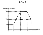
- the computing unit 101 obtains a transportation-speed changing schedule (speed on the output side of the finishing rolling mill) at positions in the longitudinal direction of the steel strip in a manner that the transportation-speed changing schedule satisfies the predetermined finishing rolling condition, as illustrated in FIG. 3 .
- the transportation-speed changing schedule may be obtained so as to be associated with positions in the longitudinal direction of the steel strip, in addition to with time from the start of the finishing rolling.
- the transportation-speed changing schedule obtained by the computing unit 101 is sent to a computing unit 102.
- the computing unit 102 sets, for example, the cooling conditions such as the cooling water amount density and the cooling length in the second cooling section 20, and an initial cooling condition in the first cooling section 10, which are necessary for adjusting the respective temperatures of the steel strip so as to fall within the target range, on the basis of the transportation-speed changing schedule, a target coiling temperature T4 of the steel strip, which has been input in advance, the input-side target steel strip temperature T2a and the output-side target steel strip temperature T2b in the second cooling section 20 and the like.
- cooling capacity (cooling speed) can be expressed as a function of water amount density
- Certain steel types are desirable to be cooled at a predetermined cooling speed for the purpose of improving the properties of the steel.
- the necessary cooling length can be obtained on the basis of the water amount density required for the necessary cooling speed and the transportation-speed changing schedule.
- the cooling conditions such as the water amount density and the cooling length are changed by controlling the supplying of water so as to be associated with the change in the transportation speed. More specifically, by setting the target temperature T2a' of the steel strip on the input side in the second cooling section at the time when the transportation speed reaches the second transportation speed in a manner that satisfies the Equation 1 described above, the water supplying is controlled in the first cooling section so as to be able to achieve this setting value of the target steel strip temperature during the process transitioning from the first transportation speed to the second transportation speed. For example, in FIG.
- the transportation speed at time B is set to the first transportation speed
- the transportation speed at time C is set to the second transportation speed.
- the target coiling temperature T4 of the steel strip is 450°C
- the target temperature T2b of the steel strip on the output side in the second cooling section 20 is set to 480°C
- the target temperature T2a of the steel strip on the input side in the second cooling section 20 is set to 600°C as the cooling conditions at the first transportation speed.
- the cooling capacities in the first cooling section 10, the second cooling section 20 and the third cooling section 30, the start temperature of the transition boiling range of the steel strip and the like are taken into consideration.
- the transportation speed changes with the advancement of the finishing rolling, as illustrated in FIG. 3 .
- the amount Tx of cooling in the second cooling section 20 (in other words, T2ax - T2bx) varies as illustrated in FIG. 5 in the case where T2ax and the cooling conditions in the second cooling section (cooling length and the cooling water amount density) remain unchanged, and a difference of the amount of cooling can be expressed as ⁇ Tx (in other words, Tx1 - Tx2) during the transition to the second transportation speed.
- T2a' - T2a the target temperature of the steel strip on the input side in the second cooling section at the first transportation speed
- T2a' the target temperature of the steel strip on the input side in the second cooling section after the transportation speed becomes the second transportation speed.
- the target temperature T2a" of the steel strip on the input side in the second cooling section during the transition from the first transportation speed to the second transportation speed can be expressed as a function of time based on the T2a and the T2a'.
- the function can be given as values associated with time, by using the time required for transitioning from the first transportation speed to the second transportation speed, and the average amount of change in temperatures per unit time ((T2a' - T2a)/t).
- T2a T2a' is established during the transition from the time A to the time B.
- the supplying of the water is controlled in the cooling section 1 so as to be the set T2a', and the steel strip is cooled in the second cooling section in a state where the cooling conditions such as the cooling length and/or the water amount density are substantially constant.
- substantially constant means that the amount of change in the cooling length falls within the range of 90% to 110%, and the amount of change in the water amount density falls within the range of 80% to 120%.
- the temperature range in which the cooling conditions are constant in the second cooling section may be set in the range of 300°C to 700°C, and more desirably, in the range of 400°C to 600°C. This is because it is possible to further reduce the deviation of the coiling temperature of the steel strip by reducing the time required for cooling under the transition boiling in the second cooling section. As illustrated in FIG.
- cooling under the transition boiling starts at steel strip temperatures of about 700°C and about 600°C, respectively, and cooling under the film boiling (A) is performed in the range of the steel strip temperatures higher than those temperatures.
- the cooling under the film boiling it is possible to obtain a stable cooling capacity (heat transfer coefficient), independently of the steel strip temperatures.
- the cooling under the transition boiling the deviation of the temperatures of the steel strip increases, because the cooling capacity sharply increases due to a decrease in the steel strip temperature, which further accelerates cooling in the lower temperature portions.
- the steel strip by cooling, in the first cooling section 10, the steel strip to the lowest temperature (600°C) at which cooling is performed under the film boiling and then, performing the rapid cooling in the second cooling section 20, it is possible to reduce the time required for cooling under the transition boiling in the second cooling section, whereby it is possible to reduce the variation in cooling caused by performing the cooling under the transition boiling state. With this process, it is possible to stably obtain the steel strip temperature on the output side in the second cooling section, whereby it is possible to further reduce the deviation of the coiling temperature of the steel strip.
- the mode of cooling the steel strip illustrated in FIG. 6 will be described in a more detail.
- the temperature of the steel strip is higher than 700°C and the rapid cooling is performed with the water amount density of 3 m 3 /min/m 2
- cooling of the steel strip is performed under the film boiling (A) under which the capacity of cooling the steel strip (heat transfer coefficient) is small. Therefore, the flow of the cooling water on the steel strip and the change in the cooling length, which does not follow the change in the transportation speed, have a small impact on the deviation of the coiling temperature of the steel strip.
- rapid cooling in the temperature range lower than 300°C does not provide sufficient effects if the amount of investment in the facilities is compared with the thus obtained effect in terms of material properties.
- the flow of the cooling water on the steel strip, and the change in the cooling length, which does not follow the change in the transportation speed, have a large impact on the uniformity of the coiling temperatures of the steel strip, and hence, it is important to prevent the occurrence of the flow of the cooling water on the steel strip and change in the cooling length in this temperature range in order to improve the uniformity of the coiling temperatures of the steel strip.
- the cooling length on the basis of the maximum value of the transportation speed in the transportation-speed changing schedule, and set the initial value of the target temperature T2a of the steel strip on the input side in the second cooling section on the basis of the minimum value of the transportation speed in the transportation-speed changing schedule.
- An example thereof includes a case where the temperature of the steel strip on the input side in the second cooling section 20 in the continuous cooling is desired to be a certain value or more.
- the transportation speed increases and decreases in an approximate straight line by accelerating and decelerating from the front end to the rear end of the steel strip.
- V(min) the minimum value of the transportation speed
- V(max) the maximum value
- V(fin) the speed at the end of finishing rolling
- V(min) is 400 mpm
- V(max) is 600 mpm
- V(fin) is 520 mpm, for example.
- the amount of cooling water is set, for example, to 3 m 3 /min/m 2 , and the cooling length is set to 3 m.
- the time required for the cooling is 1.5 times longer at the time of the transportation speed being 400 mpm, which is the minimum value. Therefore, the amount of cooling increases by about 60°C, so that the amount of cooling in the second cooling section 20 is about 180°C. Since it is desirable to set the temperature T2b of the steel strip on the output side in the second cooling section 20 to be constant, the initial setting of the target temperature T2a of the steel strip on the input side in the second cooling section 20 is set to 660°C, which is 60°C higher than 600°C.
- the amount of cooling T2a - T2b in the second cooling section 20 decreases, and hence, in response to the acceleration, the target temperature T2a' of the steel strip on the input side in the second cooling section is made decreased from the temperature of 660°C in accordance with the change in the transportation speed. Then, at the time when the transportation speed reaches the maximum speed, the target temperature T2a' of the steel strip on the input side in the second cooling section 20 is 600°C.
- the amount of cooling T2a - T2b in the second cooling section 20 increases, and thus, the target temperature T2a of the steel strip on the input side in the second cooling section is made increased again from 600°C.
- the speed V(fin) at the end of the rolling is V(min) ⁇ V(fin) ⁇ V(max)
- the relationship at the input side of the second cooling section 20 between the target steel strip temperature T2a (Vmax) at the maximum speed, the target steel strip temperature T2a (Vmin) at the minimum speed and the target steel strip temperature T2a (Vfin) at the end of the rolling is T2a (Vmax) ⁇ T2a (Vfin) ⁇ T2a (Vmin) .
- the cooling conditions in the second cooling section 20 are set such that the cooling length is determined on the basis of the maximum value of the transportation speed, and the initial value of the target temperature T2a of the steel strip on the input side in the second cooling section is set on the basis of the minimum value of the transportation speed.
- the target temperature T2a of the steel strip on the input side in the second cooling section can be made always higher than the T2a(ini), which is the initial setting value, in the continuous cooling process in which the transportation speed varies.
- the cooling of the second cooling section is started from a temperature in the vicinity of the temperature at which cooling under the transition boiling in the first cooling section 10 is started, it is possible to avoid the cooling under the transition boiling in the first cooling section 10.
- cooling is performed with the cooling length and/or the water amount density being constant independently of the transportation speed; in the first cooling section 10 and the third cooling section 30, water supplying is controlled on the basis of the transportation speed by opening and closing the valve, to cool the steel strip so as to be a predetermined coiling temperature of the steel strip; and then, the steel strip is coiled by the coiler.
- thermometers be provided on the input side and the output side of the second cooling section 20, and that the feedback control and the feed-forward control be performed by using the values from the thermometers.
- the cooling water amount density in advance, and then, obtain the cooling length such that the required amount of cooling T2a - T2b can be achieved.
- the second cooling section it is possible to perform cooling with the cooling water amount and the cooling length with which the cooling under the nucleate boiling range accounts for 80% or more. This makes it possible to suppress the variation in temperatures caused by the cooling under the transition boiling, and to cool the target in a uniform manner.
- the second cooling section may be divided into a front cooling section, a middle cooling section, and a rear cooling section.
- the temperatures of the steel strip on the output side are measured on the output side of the front cooling section.
- the cooling conditions in the middle cooling section are changed, and the steel temperature on the input side of the rear cooling section is controlled so as to fall within a predetermined range, whereby it is possible to further favorably suppress the deviation of the coiling temperature of the steel strip.
- Cooling in the third cooling section 30 may be performed by supplying cooling water as the cooling medium, gas or a mixture thereof, as well as by air cooling in which no cooling medium is supplied. This is because, by reducing the water amount density, it is possible to improve the controllability in cooling, whereby it is possible to precisely achieve the coiling temperature of the steel strip.
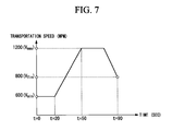
- a hot-rolled steel strip was subjected to finishing rolling in accordance with the transportation-speed changing schedule illustrated in FIG. 7 , and then, subjected to the first cooling and the second cooling.
- Table 1 shows cooling conditions and evaluation results of Examples.
- the "deviation of temperature of steel strip on input side in second cooling section” and the “deviation of coiling temperature of steel strip” each refer to deviation of temperatures obtained by continuously measuring temperatures of the center of the width of the steel strip in the direction in which the steel strip moves.
- the deviation of the steel strip temperature on the output side of the second cooling section is considered to be almost equal to the deviation of the coiling temperature of the steel strip.
- Examples C1 to C7 which are comparative examples, confirm that, even by setting the target temperature T2a' of the steel strip on the input side in the second cooling section such that the value of (T2a'-T2a)/ ⁇ Tx falls in the range of 0.8 to 1.2, the effect of suppressing the deviation of the coiling temperature of the steel strip cannot be obtained in the case where the water amount density in the second cooling section is lower than 2.0 m 2 /min/m 2 .
Abstract
Description
- The present invention relates to a method for cooling a hot-rolled steel strip.
The present application claims priority based on Japanese Patent Application No.2009-285121 - In a hot-rolling process, a hot-rolled steel strip which has passed through a finishing rolling process (hereinafter, also referred to as "steel strip") is transported from a finishing rolling mill to a down coiler. During this transportation, the steel strip is cooled to a predetermined temperature by means of a cooling device formed by plural cooling units, and then, is coiled by the down coiler. At the time of hot-rolling the steel strip, the cooling manner of the steel strip after passing through the finishing rolling process to the coiling is an important factor in determining mechanical properties of the steel strip. In general, the steel strip is cooled, for example, by using water as a cooling medium (hereinafter, also referred to as "cooling water"). In recent years, the cooling is carried out in a high temperature range at a high cooling speed (hereinafter, also referred to as "rapid cooling"), for the purpose of maintaining workability and strength more than or equal to those of the conventional steel strip while reducing additional elements such as manganese in the steel strip. Further, from the viewpoint of maintaining the uniformity of cooling, there is known a method of cooling, which avoids the cooling in a state of transition boiling, which is a primary factor of nonuniformity in cooling, as much as possible, and employs cooling in a state of nucleate boiling, under which a stable cooling capability can be obtained. In general, the cooling in the state of nucleate boiling is the rapid cooling.
- In the finishing rolling process, an accelerated rolling and a decelerated rolling are widely employed. A transportation speed of the steel strip on the output side of the finishing rolling mill is equal to a transportation speed up to the down coiler, and the steel strip is cooled in a state where the transportation speed changes. Therefore, in general, when the hot-rolled steel strip is cooled using rapid cooling, the cooling length and the water amount density of the cooling water are changed in accordance with an increase or decrease in the transportation speed of the steel strip, in order to achieve a target coiling temperature of the steel strip. For example, Patent Document 1 discloses a method of cooling in which, after the final finishing rolling milling, the length of the cooling zone is adjusted in accordance with an increase or decrease in the rolling speed of a hot-rolled steel plate such that the amount of decrease in temperature of the steel plate is constant within the steel plate. This method includes: a rapid cooling step of rapidly cooling the steel plate under a condition of a water amount density of 1000 L/min/m2 or more; and a slow cooling step of slowly cooling the hot-rolled steel plate after the rapid cooling step such that the steel plate is coiled at a predetermined coiling temperature of the steel plate.
- Further, Patent Document 2 discloses a technique in which cooling water with a water amount density of 2.0 m3/m2min or more is supplied, and the length of a cooling zone is adjusted by independently switching ON-OFF each cooling header of a first cooling header group and a second cooling header group in accordance with an increase in the transportation speed.
-
- Patent Document 1: Japanese Unexamined Patent Application, First Publication No.
2008-290156 - Patent Document 2: Japanese Patent Publication No.
4449991 - However, with the invention described in Patent Document 1, it was found that, in the case where the length of cooling performed by the cooling device was changed in accordance with a change in transportation speed of the hot-rolled steel strip by, for example, controlling opening and closing of valves provided in the cooling device, the amount of cooling of the steel strip changed greatly in accordance with an increase or decrease in the length of cooling, causing the temperature of the steel strip after the rapid cooling to significantly change. Therefore, even if the supply of water is controlled in the cooling process thereafter, deviations of the temperatures of the steel strip occurring in the rapid cooling process cannot be prevented, whereby it is extremely difficult to control the coiling temperature of the steel strip within the target range of the temperature of the steel strip.
- Further, it was also found that, in the case where part of the rapid cooling process was performed with air cooling at the time when the supply of water was controlled in the rapid cooling process, for example, by closing some of the valves for supplying the cooling water, the cooling water entered the air-cooled area from another water-supplying area, which is a main factor in causing non-uniformity of cooling. It may be possible to solve the problem described above, for example, by increasing the number of drainage units in the cooling device to prevent the cooling water from entering the area to be air-cooled. However, in the case of rapid cooling requiring a large amount of cooling water, a water drainage facility is required to have high capability, and hence, this method is not desirable because of installation limitations and cost.
- In the case where the technique described in Patent Document 2 was employed in a state where the transportation speed of the hot-rolled steel strip changes under the transition boiling state where the capacity to cool the steel strip changes greatly, it was found that the deviation of the coiling temperature of the steel strip increased for the reason described above.
- The present invention has been made in view of the reasons described above, and an object of the present invention is to provide a method for cooling a hot-rolled steel strip capable of, in cooling the hot-rolled steel strip after the finishing rolling in the hot rolling process, precisely and uniformly cooling the hot-rolled steel strip transported from the finishing rolling mill at a transportation speed with acceleration and deceleration to a predetermined coiling temperature of the steel strip.
- The present invention employs the following methods for solving the problems described above.
-
- (1) A first aspect of the present invention provides a method for cooling a hot-rolled steel strip after a finishing rolling in which a transportation speed varies, the method including: setting a transportation-speed changing schedule based on a temperature of a steel strip before the finishing rolling and a condition of the finishing rolling; performing a first cooling in which the hot-rolled steel strip is cooled under a film boiling state in a first cooling section; performing a second cooling in which the hot-rolled steel strip is cooled with a water amount density of not less than 2 m2/min/m2 in a second cooling section; and coiling the hot-rolled steel strip. In this method, a cooling condition is controlled in the first cooling such that a target temperature T2a of the steel strip on an input side in the second cooling section before a change in a transportation speed, a target temperature T2a' of the steel strip on an input side in the second cooling section after a change in the transportation speed, and a change amount ΔTx of an amount of cooling of the hot-rolled steel strip in the second cooling section, the change amount being caused by the change in the transportation speed, satisfy 0.8 ≤ (T2a' - T2a)/ΔTx ≤ 1.2 (Equation 1).
- (2) According to the method for cooling a hot-rolled steel strip of (1) above, a range of variation in a cooling length in the second cooling section may be in the range of 90% to 110% independently of a change in the transportation speed.
- (3) According to the method for cooling a hot-rolled steel strip of (1) or (2) above, a range of variation in the water amount density in the second cooling section may be in the range of 80% to 120% independently of a change in the transportation speed.
- (4) According to the method for cooling a hot-rolled steel strip of any one of (1) to (3) above, cooling under a nucleate boiling state accounts for not less than 80% of cooling duration in the second cooling section.
- (5) According to the method for cooling a hot-rolled steel strip of any one of (1) to (4) above, the method may further include: performing a third cooling in a third cooling section disposed after the second cooling section, the third cooling being formed by cooling with a cooling water of a water amount density of not less than 0.05 m3/min/m2 and not more than 0.15 m3/min/m2 and cooling with outside air.
- (6) According to the method for cooling a hot-rolled steel strip of any one of (1) to (5) above, the method may further include: setting a cooling length in the second cooling section based on a maximum value of the transportation speed in the transportation-speed changing schedule; and setting the target temperature T2a of the steel strip on the input side in the second cooling section based on a minimum value of the transportation speed in the transportation-speed changing schedule.
- (7) According to the method for cooling a hot-rolled steel strip of any one of (1) to (6), the method may further include: measuring an input-side temperature of the steel strip on the input side in the second cooling section; and changing the cooling condition in the first cooling section based on the measured input-side temperature of the steel strip, and controlling the input-side temperature of the steel strip so as to fall within a predetermined range.
- (8) According to the method for cooling a hot-rolled steel strip of any one of (1) to (7) above, the method may further include: measuring an output-side temperature of the steel strip on the output side in the second cooling section; and changing a cooling condition in a third cooling section disposed after the second cooling section on the basis of the measured output-side temperature of the steel strip, and controlling a coiling temperature of the steel strip to fall within a predetermined range.
- (9) According to the method for cooling a hot-rolled steel strip of any one of (1) to (8) above, the second cooling section may include a front cooling section, a middle cooling section, and a rear cooling section, and the method may further include: measuring an output-side temperature of the steel strip on an output side of the front cooling section; and changing a cooling condition in the middle cooling section based on the measured output-side temperature of the steel strip in the front cooling section, and controlling the temperature of the steel strip on an input side of the rear cooling section to fall within a predetermined range.
- According to the method described in (1) above, it is possible to suppress the variation in cooling caused by an increase/decrease in the cooling length and flow of the cooling water on the steel strip. In particular, it is possible to suppress the variation in cooling in the temperature range of the steel strip (from 300°C to 700°C) corresponding to the transition boiling state and the nucleate boiling state where the cooling capacity (cooling speed) sharply changes by controlling the cooling condition in the first cooling step so as to satisfy Equation 1 above in accordance with the change in the transportation speed, and setting the cooling condition in the second cooling step to be approximately constant.
According to the method described in (2) above, it is possible to suppress the variation in cooling caused by the flow of the cooling water on the steel strip and to suppress the deviation of the coiling temperature of the steel strip, by limiting the range of variation in the cooling length in the second cooling section.
According to the method described in (3) above, it is possible to suppress the variation in the cooling capacity (cooling speed) in the second cooling section and to suppress the deviation of the coiling temperature of the steel strip, by limiting the range of variation of the cooling water amount density.
According to the method described in (4) above, since it is possible to minimize the variation in cooling caused by the cooling under the transition boiling state and to suppress the deviation of the temperature of the steel strip on the output side in the second cooling section, it is possible to suppress the deviation of the coiling temperature of the steel strip.
According to the method described in (5) above, it is possible to suppress the deviation of the coiling temperature of the steel strip, by reducing the cooling water amount density in a section from the output side of the second cooling section to the coiling.
According to the method described in (6) above, since the temperature of the steel strip on the input side in the second cooling section is appropriately adjusted on the basis of the transportation-speed changing schedule, it is possible to favorably suppress the deviation of the coiling temperature of the steel strip.
According to the method described in any one of (7) to (9) above, it is possible to further favorably suppress the coiling temperature of the steel strip, by performing the feed-forward control and the feedback control based on the actually measured steel strip temperatures. -
-
FIG. 1 is a diagram schematically illustrating a configuration of a finishing rolling mill and thereafter a hot-rolling facility having a cooling device according to an embodiment. -
FIG. 2 is a diagram schematically illustrating a flow for determining cooling conditions. -
FIG. 3 is a schematic view illustrating an example of a transportation-speed changing schedule. -
FIG. 4 is a schematic view of a temperature history during a cooling process. -
FIG. 5 is a schematic view of a temperature history during the cooling process. -
FIG. 6 is a schematic view illustrating a mode of cooling a steel strip. -
FIG. 7 is a diagram illustrating a transportation-speed changing schedule used in an example. - The present inventors found that, at the time when a hot-rolled steel strip that has passed through a finishing rolling is cooled at least through a first cooling step and a second cooling step, which is a step of a rapid cooling, in a hot-rolling process in which a transportation speed varies, it is possible to suppress deviation of coiling temperatures of the steel strip by controlling the supply of water in the first cooling step so as to make cooling conditions such as cooling length and water amount density unchanged as much as possible in the second cooling step independently of change in the transportation speed, even when the transportation speed of the hot-rolled steel strip varies. More specifically, the present inventors found that it is possible to suppress the deviation of coiling temperature of the steel strip by controlling the cooling conditions in the first cooling step so as to satisfy:

where T2a is a target temperature of the hot-rolled steel strip on the input side in a second cooling section before the transportation speed varies; T2a' is a target temperature of the hot-rolled steel strip on the input side in the second cooling section after the transportation speed varies; and ΔTx is the amount of change in the amount of cooling of the hot-rolled steel strip in the second cooling section, the change being due to the occurrence of the change in rolling speed. - Hereinbelow, with reference to the drawings, a description will be made of a cooling device 1 and a method for cooling a steel strip S according to an embodiment of the present invention based on the findings described above.
-
FIG. 1 schematically illustrates a configuration of a finishing rolling mill 2 and thereafter a hot-rolling facility having the cooling device 1 according to this embodiment. - As illustrated in
FIG. 1 , the hot-rolling facility includes the finishing rolling mill 2, a cooling device 1, and acoiler 3, which are disposed in this order in the transportation direction of the steel strip S. The finishing rolling mill 2 continuously rolls the steel strip S that has been discharged from a heating furnace (not shown) and has been rolled by a rough-rolling mill (not shown) with the continuous rolling being accelerated or decelerated in accordance with a transportation-speed changing schedule. The cooling device 1 cools the steel strip S after a finishing rolling to a predetermined coiling temperature of the steel strip of, for example, 300°C. Thecoiler 3 coils the cooled steel stripS. A thermometer 51 for measuring a finishing-rolling temperature T0 of the steel strip is provided on the upstream side of the finishing rolling mill 2, and a run-out table 4 formed bytable rolls 4a is provided between the finishing rolling mill 2 and thecoiler 3. The steel strip S that has been rolled by the finishing rolling mill 2 is cooled by the cooling device 1 while being transported on the run-out table 4, and then, is coiled by thecoiler 3. - A
first cooling unit 10a that cools, in afirst cooling section 10, the steel strip S immediately after passing through the finishing rolling mill 2 is provided on the upstream side in the cooling device 1, in other words, at a position immediately downstream of the finishing rolling mill 2. As illustrated inFIG. 1 , thefirst cooling unit 10a is provided with plurallaminar nozzles 11 that spray the cooling water, for example, onto a surface of the steel strip S, the laminar nozzles being arranged in the width direction and the transportation direction of the steel strip S. The water amount density of the cooling water sprayed from thelaminar nozzles 11 onto the surface of the steel strip S is set, for example, to 0.3 m3/m2/min. Thefirst cooling section 10 refers to a section in which the steel strip S is cooled under a film boiling state by thefirst cooling unit 10a. In addition to spraying the cooling water through the laminar nozzles, cooling in thefirst cooling section 10 may be performed, for example, by spraying the cooling water by a spray nozzle, by gas cooling using an air nozzle, by combination of gas and water using a gas-water nozzle (mist cooling), or by air cooling in which no cooling medium is supplied. Note that the "cooled under a film boiling state" includes a cooling state where cooling in the film boiling range is performed in a part of the first cooling section while air-cooling is performed in the remainder of the section, in addition to a state where cooling under the film boiling state is performed in the entire first cooling section. - As illustrated in
FIG. 1 , on the downstream side of thefirst cooling unit 10a, there is provided asecond cooling unit 20a that rapidly cools, in the second cooling section 20 (rapid cooling section), the steel strip S that has been cooled in thefirst cooling section 10. Thesecond cooling section 20 refers to a section in which thesecond cooling unit 20a cools the steel strip S. The term "rapidly cools" as used in this embodiment refers to a cooling process in which the cooling water amount density is set at least to 2 m3/min/m2 or more, desirably to 3 m3/min/m2 or more. The term "cooling water amount density" means the amount of cooling water supplied per unit 1 m2 on the target surface of the steel strip, and in the case of cooling only the upper surface of the steel strip, means the amount of cooling water supplied per unit 1 m2 on the upper surface of the steel strip. Thesecond cooling unit 20a is provided, for example, with spray nozzles 21 that spray the cooling water onto the upper surface of the steel strip S while being arranged in the transportation direction and the width direction of the steel strip, and has a capability to provide the cooling water amount density, for example, of 2 m3/min/m2, desirably of 3 m3/m2/min or more to the steel strip S. With respect to the entire cooling mode in this second cooling section, thesecond cooling unit 20a has a capability to cool 80% or more of the cooling duration in the second cooling section under the nucleate boiling. - As illustrated in
FIG. 3 , athird cooling unit 30a that cools athird cooling section 30 may be provided on the downstream side of thesecond cooling unit 20a. Similar to thefirst cooling unit 10a, thethird cooling unit 30a is provided with plurallaminar nozzles 11 that spray the cooling water onto the surface of the steel strip S while being arranged in the width direction and the transportation direction of the steel strip S. The water amount density of the cooling water sprayed from thelaminar nozzles 11 onto the surface of the steel strip S is set, for example, to 0.3 m3/m2/min. In addition to by spraying the cooling water through the laminar nozzles, cooling in thethird cooling section 30 may be performed, for example, by spraying the cooling water by a spray nozzle, by gas cooling using an air nozzle, by combination of gas and water using a gas-water nozzle (mist cooling), or by air cooling in which no cooling medium is supplied. -
Thermometers first cooling section 10, respectively. Further, a thermometer 54 for measuring an output-side steel strip temperature is provided on the output side of thesecond cooling section 20. Athermometer 55 for measuring a coiling temperature of the steel strip is provided on the upstream side of thecoiler 3. The temperatures of the steel strip at the time of cooling the steel strip are measured on an as-needed basis, and feed-forward control and feedback control are performed in thefirst cooling section 10 and thethird cooling section 30 on the basis of the measured values from the thermometers. - Next, with reference to
FIG. 2 to FIG. 6 , a description will be made of a method for cooling the hot-rolled steel strip S according to this embodiment, the method at least including a first cooling step, a second cooling step, and a coiling step. Note that the description will be made on the assumption that thethird cooling unit 30a is provided.
FIG. 2 illustrates a flow of determining cooling conditions in thesecond cooling section 20 at the time of starting the cooling of the hot-rolled steel strip. - The steel strip after completion of rough rolling is transported to the finishing rolling mill 2, and the finishing-rolling steel strip temperatures thereof are measured by the
thermometer 51. Data of the measured temperatures are input to acomputing unit 101. On the basis of the temperatures of the steel strip and a predetermined finishing rolling condition such as thickness, which has been input in advance, thecomputing unit 101 obtains a transportation-speed changing schedule (speed on the output side of the finishing rolling mill) at positions in the longitudinal direction of the steel strip in a manner that the transportation-speed changing schedule satisfies the predetermined finishing rolling condition, as illustrated inFIG. 3 . The transportation-speed changing schedule may be obtained so as to be associated with positions in the longitudinal direction of the steel strip, in addition to with time from the start of the finishing rolling. - The transportation-speed changing schedule obtained by the
computing unit 101 is sent to acomputing unit 102. Thecomputing unit 102 sets, for example, the cooling conditions such as the cooling water amount density and the cooling length in thesecond cooling section 20, and an initial cooling condition in thefirst cooling section 10, which are necessary for adjusting the respective temperatures of the steel strip so as to fall within the target range, on the basis of the transportation-speed changing schedule, a target coiling temperature T4 of the steel strip, which has been input in advance, the input-side target steel strip temperature T2a and the output-side target steel strip temperature T2b in thesecond cooling section 20 and the like. Since the cooling capacity (cooling speed) can be expressed as a function of water amount density, it is possible to set the necessary water amount density and cooling length by obtaining the time required for passing through the cooling section on the basis of the transportation-speed changing schedule. Certain steel types are desirable to be cooled at a predetermined cooling speed for the purpose of improving the properties of the steel. For such steels, the necessary cooling length can be obtained on the basis of the water amount density required for the necessary cooling speed and the transportation-speed changing schedule. In a similar manner, it is possible to set the initial cooling conditions in thefirst cooling section 10 and thethird cooling section 30 on the basis of the target coiling temperature T4 of the steel strip, the target steel strip temperature T2b on the output side in the second cooling section, the target steel strip temperature T2a on the input side in the second cooling section and the target steel strip temperature T0a on the output side of the finishing rolling. - In the continuous cooling process in the
first cooling section 10 and thethird cooling section 30, the cooling conditions such as the water amount density and the cooling length are changed by controlling the supplying of water so as to be associated with the change in the transportation speed. More specifically, by setting the target temperature T2a' of the steel strip on the input side in the second cooling section at the time when the transportation speed reaches the second transportation speed in a manner that satisfies the Equation 1 described above, the water supplying is controlled in the first cooling section so as to be able to achieve this setting value of the target steel strip temperature during the process transitioning from the first transportation speed to the second transportation speed. For example, inFIG. 3 , it is assumed that the transportation speed at time B is set to the first transportation speed, and the transportation speed at time C is set to the second transportation speed. For example, in the case where the target coiling temperature T4 of the steel strip is 450°C, the target temperature T2b of the steel strip on the output side in thesecond cooling section 20 is set to 480°C, and the target temperature T2a of the steel strip on the input side in thesecond cooling section 20 is set to 600°C as the cooling conditions at the first transportation speed. At the time of setting the T2a and the T2b, the cooling capacities in thefirst cooling section 10, thesecond cooling section 20 and thethird cooling section 30, the start temperature of the transition boiling range of the steel strip and the like are taken into consideration. Of the setting values described above, the amount of cooling of the steel strip in thesecond cooling section 20 at the first transportation speed is T2a - T2b = 120°C, and the cooling conditions such as the cooling length and the water amount density in the second cooling section are determined so as to be able to achieve the equation. - During a continuous cooling process in which the transportation speed transitions to the second transportation speed, the transportation speed changes with the advancement of the finishing rolling, as illustrated in
FIG. 3 . On the other hand, the amount Tx of cooling in the second cooling section 20 (in other words, T2ax - T2bx) varies as illustrated inFIG. 5 in the case where T2ax and the cooling conditions in the second cooling section (cooling length and the cooling water amount density) remain unchanged, and a difference of the amount of cooling can be expressed as ΔTx (in other words, Tx1 - Tx2) during the transition to the second transportation speed. Therefore, at the time of transitioning from the first transportation speed to the second transportation speed, it is necessary to set the target temperature of the steel strip on the input side in the second cooling section and perform adjustment by controlling the water supplied in the first cooling section, by taking the amount of change in Tx into consideration. Setting described above is made by considering the control accuracy in the cooling section 1 in the range that falls within 0.8 ≤ (T2a' - T2a)/ΔTx ≤ 1.2, desirably, 0.9 ≤ (T2a' - T2a)/ΔTx ≤ 1.1, where T2a is the target temperature of the steel strip on the input side in the second cooling section at the first transportation speed, and T2a' is the target temperature of the steel strip on the input side in the second cooling section after the transportation speed becomes the second transportation speed. The target temperature T2a" of the steel strip on the input side in the second cooling section during the transition from the first transportation speed to the second transportation speed can be expressed as a function of time based on the T2a and the T2a'. For example, the function can be given as values associated with time, by using the time required for transitioning from the first transportation speed to the second transportation speed, and the average amount of change in temperatures per unit time ((T2a' - T2a)/t). Further, inFIG. 3 , in the case where the first transportation speed is a transportation speed at time A and the second transportation speed is a transportation speed at time B, the transportation speed is constant during the transition from the time A to the time B, and hence, ΔTx is zero in this transition. Therefore, T2a = T2a' is established during the transition from the time A to the time B. The supplying of the water is controlled in the cooling section 1 so as to be the set T2a', and the steel strip is cooled in the second cooling section in a state where the cooling conditions such as the cooling length and/or the water amount density are substantially constant. Note that the wording "substantially constant" means that the amount of change in the cooling length falls within the range of 90% to 110%, and the amount of change in the water amount density falls within the range of 80% to 120%. Further, in a similar manner, in the case where the transportation speed schedule is obtained with respect to the longitudinal direction of the steel strip, it is possible to set a new target steel strip temperature T2a' so as to be associated with positions in the longitudinal direction of the steel strip. - Since cooling in the film boiling range is performed in the
first cooling section 10, it is possible to precisely achieve the temperature of the steel strip on the input side in the second cooling section by controlling the supplying of the water in accordance with the change in the transportation speed, and to make the cooling length and the cooling water amount density of thesecond cooling unit 20a almost unchanged in thesecond cooling section 20. This makes it possible to: remove the external cooling disturbance caused by entry of the water existing on the steel strip resulting from ON/OFF of the water-supplying valve; suppress the deviation of the temperature of the steel strip on the output side in the second cooling section; and precisely achieve the coiling temperature of the steel strip. - The temperature range in which the cooling conditions are constant in the second cooling section may be set in the range of 300°C to 700°C, and more desirably, in the range of 400°C to 600°C. This is because it is possible to further reduce the deviation of the coiling temperature of the steel strip by reducing the time required for cooling under the transition boiling in the second cooling section. As illustrated in
FIG. 6 , in the case where the water amount density in thesecond cooling section 20 is 3 m3/min/m2 and the water amount density in thefirst cooling section 10 is 0.3 m3/m2/min, cooling under the transition boiling (B) starts at steel strip temperatures of about 700°C and about 600°C, respectively, and cooling under the film boiling (A) is performed in the range of the steel strip temperatures higher than those temperatures. With the cooling under the film boiling, it is possible to obtain a stable cooling capacity (heat transfer coefficient), independently of the steel strip temperatures. On the other hand, with the cooling under the transition boiling, the deviation of the temperatures of the steel strip increases, because the cooling capacity sharply increases due to a decrease in the steel strip temperature, which further accelerates cooling in the lower temperature portions.
Therefore, by cooling, in thefirst cooling section 10, the steel strip to the lowest temperature (600°C) at which cooling is performed under the film boiling and then, performing the rapid cooling in thesecond cooling section 20, it is possible to reduce the time required for cooling under the transition boiling in the second cooling section, whereby it is possible to reduce the variation in cooling caused by performing the cooling under the transition boiling state. With this process, it is possible to stably obtain the steel strip temperature on the output side in the second cooling section, whereby it is possible to further reduce the deviation of the coiling temperature of the steel strip. - The mode of cooling the steel strip illustrated in
FIG. 6 will be described in a more detail. In the case where the temperature of the steel strip is higher than 700°C and the rapid cooling is performed with the water amount density of 3 m3/min/m2, cooling of the steel strip is performed under the film boiling (A) under which the capacity of cooling the steel strip (heat transfer coefficient) is small. Therefore, the flow of the cooling water on the steel strip and the change in the cooling length, which does not follow the change in the transportation speed, have a small impact on the deviation of the coiling temperature of the steel strip. Further, rapid cooling in the temperature range lower than 300°C does not provide sufficient effects if the amount of investment in the facilities is compared with the thus obtained effect in terms of material properties. In general, rapid cooling of the steel strip in the temperature range of 300°C to 700°C provides an advantage in obtaining predetermined material properties. However, in this temperature range, the steel strip is cooled under the transition boiling (B) and the nucleate boiling (C). In the transition boiling, capacity of cooling the steel strip sharply increases with decrease in the steel strip temperature, whereas cooling under the nucleate boiling state provides five to almost 10 times larger cooling capacity than that obtained in the film boiling state when performed with the same amount of water. More specifically, the flow of the cooling water on the steel strip, and the change in the cooling length, which does not follow the change in the transportation speed, have a large impact on the uniformity of the coiling temperatures of the steel strip, and hence, it is important to prevent the occurrence of the flow of the cooling water on the steel strip and change in the cooling length in this temperature range in order to improve the uniformity of the coiling temperatures of the steel strip. - At the time when the cooling conditions in the
second cooling section 20 are determined, it may be possible to determine the cooling length on the basis of the maximum value of the transportation speed in the transportation-speed changing schedule, and set the initial value of the target temperature T2a of the steel strip on the input side in the second cooling section on the basis of the minimum value of the transportation speed in the transportation-speed changing schedule. An example thereof includes a case where the temperature of the steel strip on the input side in thesecond cooling section 20 in the continuous cooling is desired to be a certain value or more. - Next, description will be made of a method for setting the initial cooling conditions in the
second cooling section 20 by determining the cooling length on the basis of the maximum value of the transportation speed in the transportation speed schedule, and setting an initial value of the target temperature T2a of the steel strip on the input side in the second cooling section on the basis of the minimum value of the transportation speed. InFIG. 3 , the transportation speed increases and decreases in an approximate straight line by accelerating and decelerating from the front end to the rear end of the steel strip. InFIG. 3 , the minimum value of the transportation speed is denoted by V(min), the maximum value is denoted by V(max), and the speed at the end of finishing rolling is denoted by V(fin). - As described above, for example, the amount of cooling in the
second cooling section 20 is T2a - T2b = 120°C in the case where the target coiling temperature T4 of the steel strip is set to 450°C, the target temperature T2b of the steel strip on the output side in thesecond cooling section 20 is set to 480°C, and the target temperature T2a of the steel strip on the input side in thesecond cooling section 20 is set to 600°C. For the transportation speed of the steel strip, V(min) is 400 mpm, V(max) is 600 mpm and V(fin) is 520 mpm, for example. As the initial settings of the cooling conditions in thesecond cooling section 20 under which the cooling of 120°C can be achieved at the time when the steel strip is transported at 600 mpm, the amount of cooling water is set, for example, to 3 m3/min/m2, and the cooling length is set to 3 m. - In the case where cooling is performed under the cooling conditions described above, the time required for the cooling is 1.5 times longer at the time of the transportation speed being 400 mpm, which is the minimum value. Therefore, the amount of cooling increases by about 60°C, so that the amount of cooling in the
second cooling section 20 is about 180°C. Since it is desirable to set the temperature T2b of the steel strip on the output side in thesecond cooling section 20 to be constant, the initial setting of the target temperature T2a of the steel strip on the input side in thesecond cooling section 20 is set to 660°C, which is 60°C higher than 600°C. - In the acceleration section, the amount of cooling T2a - T2b in the
second cooling section 20 decreases, and hence, in response to the acceleration, the target temperature T2a' of the steel strip on the input side in the second cooling section is made decreased from the temperature of 660°C in accordance with the change in the transportation speed. Then, at the time when the transportation speed reaches the maximum speed, the target temperature T2a' of the steel strip on the input side in thesecond cooling section 20 is 600°C. - When the finishing rolling further advances and enters the deceleration section, the amount of cooling T2a - T2b in the
second cooling section 20 increases, and thus, the target temperature T2a of the steel strip on the input side in the second cooling section is made increased again from 600°C. Since the speed V(fin) at the end of the rolling is V(min) < V(fin) < V(max), the relationship at the input side of thesecond cooling section 20 between the target steel strip temperature T2a(Vmax) at the maximum speed, the target steel strip temperature T2a(Vmin) at the minimum speed and the target steel strip temperature T2a(Vfin) at the end of the rolling is T2a(Vmax) < T2a(Vfin) < T2a(Vmin). - As described above, the cooling conditions in the
second cooling section 20 are set such that the cooling length is determined on the basis of the maximum value of the transportation speed, and the initial value of the target temperature T2a of the steel strip on the input side in the second cooling section is set on the basis of the minimum value of the transportation speed. With this setting, the target temperature T2a of the steel strip on the input side in the second cooling section can be made always higher than the T2a(ini), which is the initial setting value, in the continuous cooling process in which the transportation speed varies. In the case where the cooling of the second cooling section is started from a temperature in the vicinity of the temperature at which cooling under the transition boiling in thefirst cooling section 10 is started, it is possible to avoid the cooling under the transition boiling in thefirst cooling section 10. - In the
second cooling section 20, cooling is performed with the cooling length and/or the water amount density being constant independently of the transportation speed; in thefirst cooling section 10 and thethird cooling section 30, water supplying is controlled on the basis of the transportation speed by opening and closing the valve, to cool the steel strip so as to be a predetermined coiling temperature of the steel strip; and then, the steel strip is coiled by the coiler. - For controlling the water supplying in the
first cooling section 10 and thethird cooling section 30, it is desirable that the thermometers be provided on the input side and the output side of thesecond cooling section 20, and that the feedback control and the feed-forward control be performed by using the values from the thermometers. By using the actually measured steel strip temperatures in controlling, it is possible to precisely achieve the target temperature T2a of the steel strip on the input side in the second cooling section, and the coiling temperature of the steel strip. - At the time of determining the cooling conditions in the second cooling section, it may be possible to determine the cooling water amount density in advance, and then, obtain the cooling length such that the required amount of cooling T2a - T2b can be achieved. For example, it may be possible to designate in advance certain types of steels as steels to be cooled with the cooling water amount density of 3 m3/min/m2, and then, to determine the cooling length.
- In the second cooling section, it is possible to perform cooling with the cooling water amount and the cooling length with which the cooling under the nucleate boiling range accounts for 80% or more. This makes it possible to suppress the variation in temperatures caused by the cooling under the transition boiling, and to cool the target in a uniform manner.
- The second cooling section may be divided into a front cooling section, a middle cooling section, and a rear cooling section. In this case, the temperatures of the steel strip on the output side are measured on the output side of the front cooling section. On the basis of the measured output-side steel strip temperature in the front cooling section, the cooling conditions in the middle cooling section are changed, and the steel temperature on the input side of the rear cooling section is controlled so as to fall within a predetermined range, whereby it is possible to further favorably suppress the deviation of the coiling temperature of the steel strip.
- In the
third cooling section 30, it may be possible to perform cooling with the water amount density of the cooling water in the range of not less than 0.05 m3/min/m2 and 0.15 m3/min/m2. Cooling in thethird cooling section 30 may be performed by supplying cooling water as the cooling medium, gas or a mixture thereof, as well as by air cooling in which no cooling medium is supplied. This is because, by reducing the water amount density, it is possible to improve the controllability in cooling, whereby it is possible to precisely achieve the coiling temperature of the steel strip. - Next, a description will be made of Examples A1 to A7, Examples B1 to B7, Examples of C1 to C7, and Examples D1 to D7, each of which employs the finishing rolling mill, the first cooling unit, the second cooling unit, and the coiler.
- In each of Examples, a hot-rolled steel strip was subjected to finishing rolling in accordance with the transportation-speed changing schedule illustrated in
FIG. 7 , and then, subjected to the first cooling and the second cooling. Table 1 shows cooling conditions and evaluation results of Examples. InFIG. 7 , t = 0 indicates a time when the top end portion of the hot-rolled steel strip reaches the first cooling section, and t = 90 indicates a time when the rear end portion of the hot-rolled steel strip reaches the coiler. In the present Examples, evaluation was made by setting the first transportation speed to be a transportation speed at t = 20, and setting the second transportation speed to be a transportation speed at t = 50. It should be noted that the target temperature of the steel strip on the output side in the second cooling section is set at 400°C. - [Table 1]
Table 1 Target temperature T2a of steel strip on input side in second cooling section at t=20 Cooling amount Tx1 in second cooling section at t=20 Cooling amount Tx2 in second cooling section t=50 Change amount ΔTx of cooling amount in second cooling section between t=20 to t=50 (T2a'-T2a) /(ΔTx) Target temperature T2a' of steel strip on input of side in second cooling section at t=50 Deviation of temperature of steel strip on input side in second cooling section Deviation of coiling temperature of steel strip Water amount density in second cooling section at t=20 Water amount density in second cooling section at t=50 Cooling length in second cooling section at t=20 Cooling length in second cooling section at t=50 Range of variation in cooling length in second cooling section (Ratio) °C °C °C °C °C m3/min/m2 m3/min/m2 m m Example A1 700 200 100 100 0,7 630 9,6 14,6 3,0 3,0 6,0 6,9 1,15 Example A2 0,8 620 9,8 13,2 6,6 1,1 Example A3 0,9 610 9,4 12,9 6,3 1,05 Example A4 1 600 9,5 12,7 6,0 1 Example A5 1,1 590 9,6 12,9 5,7 0,95 Example A6 1,2 580 9,7 13,2 5,4 0,9 Example A7 1,3 570 9,6 14,4 5,1 0,85 Example B1 700 200 100 100 0,7 630 9,7 14,9 2,0 2,0 8,4 9,7 1,15 Example B2 0,8 620 9,9 13,8 9,2 1,1 Example B3 0,9 610 9,6 13,4 8,8 1,05 Example B4 1 600 9,8 13,1 8,4 1 Example B5 1,1 590 9,8 13,6 8,0 0,95 Example B6 1,2 580 9,9 13,9 7,6 0,9 Example B7 1,3 570 9,7 15,1 7,1 0,85 Example C1 700 200 100 100 0,7 630 9,8 15,8 1,5 1,5 10,5 12,1 1,15 Example C2 0,8 620 9,9 15,3 11,6 1,1 Example C3 0,9 610 9,7 14,9 11,0 1,05 Example C4 1 600 9,6 14,7 10,5 1 Example C5 1,1 590 9,6 15,1 10,0 0,95 Example C6 1,2 580 9,9 15,5 9,5 0,9 Example C7 1,3 570 9,8 16,2 8,9 0,85 Example D1 0,7 630 9,6 14,8 4,4 1,45 Example D2 0,8 620 9,9 13,3 3,9 1,30 Example D3 0,9 610 9,7 12,9 3,4 1,15 Example D4 700 200 100 100 1 600 9,6 12,5 3,0 3,0 6,0 6,0 1,00 Example D5 1,1 590 9,7 13,1 2,6 0,87 Example D6 1,2 580 9,9 13,3 2,3 0,77 Example D7 1,3 570 9,8 14,9 2,1 0,69 - In Table 1, the "deviation of temperature of steel strip on input side in second cooling section" and the "deviation of coiling temperature of steel strip" each refer to deviation of temperatures obtained by continuously measuring temperatures of the center of the width of the steel strip in the direction in which the steel strip moves.
- In the present Examples, since the steel strip was air cooled from the output of the second cooling section to the coiling, the deviation of the steel strip temperature on the output side of the second cooling section is considered to be almost equal to the deviation of the coiling temperature of the steel strip.
- The results of these Examples confirm that the effect of suppressing the deviation of the coiling temperature of the steel strip can be obtained by setting the target temperature T2a' of the steel strip on the input side in the second cooling section such that the value of (T2a'-T2a)/ΔTx falls in the range of 0.8 to 1.2.
Furthermore, the results of Examples C1 to C7, which are comparative examples, confirm that, even by setting the target temperature T2a' of the steel strip on the input side in the second cooling section such that the value of (T2a'-T2a)/ΔTx falls in the range of 0.8 to 1.2, the effect of suppressing the deviation of the coiling temperature of the steel strip cannot be obtained in the case where the water amount density in the second cooling section is lower than 2.0 m2/min/m2. - As described above, the preferred embodiment of the present invention has been described with reference to the attached drawings. However, the present invention is not limited to the examples. Apparently, the skilled person in the art can reach various change examples or modification examples within the scope of the Claimed technical principle. It is understood that these example changes or modification examples are naturally included in the technical scope of the present invention.
- According to the present invention, it is possible to precisely and uniformly cool a hot-rolled steel strip transported from a finishing rolling mill at a transportation speed with acceleration and deceleration, to achieve a predetermined coiling temperature of the steel strip.
-
- 1
- Cooling device
- 2
- Finishing rolling mill
- 3
- Coiler
- 4
- Run-out table
- 4a
- Table roll
- 10
- First cooling section
- 10a
- First cooling unit
- 11
- Laminar nozzle
- 20
- Second cooling section (rapid cooling section)
- 20a
- Second cooling unit (rapid cooling unit)
- 21
- Spray nozzle (on the upper surface side)
- 30
- Third cooling section
- 30a
- Third cooling unit
- 40
- Control unit
- 51, 52, 53, 54, 55
- Thermometer
- S
- Steel strip
- V(min)
- Minimum transportation speed
- V(max)
- Maximum transportation speed
- V(fin)
- Transportation speed at the end of finishing rolling
- T2a(Vmin)
- Target temperature of steel strip on the input side of second cooling section at minimum transportation speed
- T2a(Vmax)
- Target temperature of steel strip on the input side of second cooling section at maximum transportation speed
- T2a(Vfin)
- Target temperature of steel strip on the input side of second cooling section with respect to a transportation speed at the end of finishing rolling
- (A)
- Cooling under film boiling
- (B)
- Cooling under transition boiling
- (C)
- Cooling under nucleate boiling
Claims (9)
- A method for cooling a hot-rolled steel strip after a finishing rolling in which a transportation speed varies, the method including:setting a transportation-speed changing schedule based on a temperature of a steel strip before the finishing rolling and a condition of the finishing rolling;performing a first cooling in which the hot-rolled steel strip is cooled under a film boiling state in a first cooling section;performing a second cooling in which the hot-rolled steel strip is cooled with a water amount density of not less than 2 m2/min/m2 in a second cooling section; andcoiling the hot-rolled steel strip, whereina cooling condition is controlled in the first cooling such that a target temperature T2a of the steel strip on an input side in the second cooling section before a change in a speed of rolling, a target temperature T2a' of the steel strip on an input side in the second cooling section after a change in the speed of rolling, and a change amount ΔTx of an amount of cooling the hot-rolled steel strip in the second cooling section, the change amount being caused by the change in the speed of rolling, satisfy 0.8 ≤ (T2a' - T2a)/ΔTx ≤ 1.2 (Equation 1).
- The method for cooling a hot-rolled steel strip according to Claim 1, wherein
a range of variation in a cooling length in the second cooling section is in the range of 90% to 110% independently of change in the transportation speed. - The method for cooling a hot-rolled steel strip according to Claim 1 or 2, wherein
a range of variation in the water amount density in the second cooling section is in the range of 80% to 120% independently of change in the transportation speed. - The method for cooling a hot-rolled steel strip according to any one of Claims 1 to 3, wherein
cooling under a nucleate boiling state accounts for not less than 80% of cooling duration in the second cooling section. - The method for cooling a hot-rolled steel strip according to any one of Claims 1 to 4, the method further including:performing a third cooling in a third cooling section disposed after the second cooling section, the third cooling being formed by cooling with a cooling water of water amount density of not less than 0.05 m3/min/m2 and not more than 0.15 m3/min/m2 and cooling with outside air.
- The method for cooling a hot-rolled steel strip according to any one of Claims 1 to 5, the method further including:setting a cooling length in the second cooling section based on a maximum value of the transportation speed in the transportation-speed changing schedule; andsetting the target temperature T2a of the steel strip on the input side in the second cooling section based on a minimum value of the transportation speed in the transportation-speed changing schedule.
- The method for cooling a hot-rolled steel strip according to any one of Claims 1 to 6, the method further including:measuring an input-side temperature of the steel strip on the input side in the second cooling section; andchanging the cooling condition in the first cooling section based on the measured input-side temperature of the steel strip, and controlling the input-side temperature of the steel strip so as to fall within a predetermined range.
- The method for cooling a hot-rolled steel strip according to any one of Claims 1 to 7, the method further including:measuring an output-side temperature of the steel strip on the output side in the second cooling section; andchanging a cooling condition in a third cooling section disposed after the second cooling section on the basis of the measured output-side temperature of the steel strip, and controlling a coiling temperature of the steel strip to fall within a predetermined range.
- The method for cooling a hot-rolled steel strip according to any one of Claims 1 to 8, wherein
the second cooling section includes a front cooling section, a middle cooling section, and a rear cooling section, and
the method further includes:measuring an output-side temperature of the steel strip on an output side of the front cooling section; andchanging a cooling condition in the middle cooling section based on the measured output-side temperature of the steel strip in the front cooling section, and controlling the temperature of the steel strip on an input side of the rear cooling section to fall within a predetermined range.
Applications Claiming Priority (2)
| Application Number | Priority Date | Filing Date | Title |
|---|---|---|---|
| JP2009285121 | 2009-12-16 | ||
| PCT/JP2010/072639 WO2011074632A1 (en) | 2009-12-16 | 2010-12-16 | Method for cooling hot-rolled steel plate |
Publications (3)
| Publication Number | Publication Date |
|---|---|
| EP2465620A1 true EP2465620A1 (en) | 2012-06-20 |
| EP2465620A4 EP2465620A4 (en) | 2012-10-03 |
| EP2465620B1 EP2465620B1 (en) | 2013-07-03 |
Family
ID=44167383
Family Applications (1)
| Application Number | Title | Priority Date | Filing Date |
|---|---|---|---|
| EP10837657.5A Active EP2465620B1 (en) | 2009-12-16 | 2010-12-16 | Method for cooling hot-rolled steel strip |
Country Status (9)
| Country | Link |
|---|---|
| US (1) | US8359894B2 (en) |
| EP (1) | EP2465620B1 (en) |
| JP (1) | JP4938159B2 (en) |
| KR (1) | KR101211273B1 (en) |
| CN (1) | CN102481610B (en) |
| BR (1) | BR112012004729B1 (en) |
| IN (1) | IN2012DN00945A (en) |
| TW (1) | TWI379010B (en) |
| WO (1) | WO2011074632A1 (en) |
Cited By (3)
| Publication number | Priority date | Publication date | Assignee | Title |
|---|---|---|---|---|
| CN104001742A (en) * | 2014-05-21 | 2014-08-27 | 中冶南方工程技术有限公司 | Method for achieving controlled cooling on rolled pieces between and after bar finishing mill units |
| EP3050992A4 (en) * | 2013-09-26 | 2017-10-11 | Peking University Founder Group Co., Ltd | Production process for non-quenched and tempered steel |
| CN107249770A (en) * | 2015-02-27 | 2017-10-13 | 首要金属科技奥地利有限责任公司 | Winding apparatus with the Asymmetrical cooling to winding band |
Families Citing this family (21)
| Publication number | Priority date | Publication date | Assignee | Title |
|---|---|---|---|---|
| FI20070622L (en) * | 2007-08-17 | 2009-04-15 | Outokumpu Oy | Method and device for checking evenness during cooling of a strip made of stainless steel |
| US9186710B2 (en) | 2011-06-07 | 2015-11-17 | Nippon Steel & Sumitomo Metal Corporation | Method for cooling hot-rolled steel sheet |
| US9566625B2 (en) | 2011-06-07 | 2017-02-14 | Nippon Steel & Sumitomo Metal Corporation | Apparatus for cooling hot-rolled steel sheet |
| US9211574B2 (en) | 2011-07-27 | 2015-12-15 | Nippon Steel & Sumitomo Metal Corporation | Method for manufacturing steel sheet |
| KR101376565B1 (en) * | 2011-12-15 | 2014-04-02 | (주)포스코 | Method and apparatus for controlling the temperature of strip in the rapid cooling section of continuous annealing line |
| BR112013028746B1 (en) * | 2012-12-06 | 2022-08-09 | Nippon Steel Corporation | EQUIPMENT FOR COOLING HOT-LAMINATED STEEL SHEET |
| JP5741634B2 (en) * | 2013-04-03 | 2015-07-01 | Jfeスチール株式会社 | Method and apparatus for cooling control of hot-rolled steel sheet |
| CA2951791C (en) * | 2014-07-24 | 2018-11-20 | Nippon Steel & Sumitomo Metal Corporation | Method for cooling steel strip and cooling apparatus |
| CN104438356B (en) * | 2014-09-23 | 2017-04-05 | 北京首钢股份有限公司 | A kind of method for improving Thin container plate edge shape wave |
| CN104668295B (en) * | 2015-02-13 | 2017-04-12 | 中冶南方工程技术有限公司 | Control method and control device of rod and wire production line temperature control rolling process |
| JP6245766B2 (en) * | 2015-05-26 | 2017-12-13 | Primetals Technologies Japan株式会社 | Hot-rolled steel plate cooling apparatus and mask member position adjusting method |
| CA3026506A1 (en) | 2016-05-10 | 2017-11-16 | United States Steel Corporation | High strength steel products and annealing processes for making the same |
| US11560606B2 (en) | 2016-05-10 | 2023-01-24 | United States Steel Corporation | Methods of producing continuously cast hot rolled high strength steel sheet products |
| JP6583561B2 (en) * | 2016-08-09 | 2019-10-02 | 東芝三菱電機産業システム株式会社 | Outlet temperature control system of rolling mill |
| WO2018037916A1 (en) * | 2016-08-22 | 2018-03-01 | Jfeスチール株式会社 | High-temperature metal cooling method and hot-dip-galvanized steel strip producing method |
| BR112021003034A2 (en) * | 2018-09-19 | 2021-05-11 | Nippon Steel Corporation | cooling device for hot rolled steel sheet and hot rolled steel sheet cooling method |
| AU2020268370A1 (en) | 2019-05-07 | 2021-12-02 | United States Steel Corporation | Methods of producing continuously cast hot rolled high strength steel sheet products |
| AU2020325050A1 (en) | 2019-08-07 | 2022-02-24 | United States Steel Corporation | High ductility zinc-coated steel sheet products |
| JP2022544765A (en) | 2019-08-19 | 2022-10-21 | ユナイテッド ステイツ スチール コーポレイション | High strength steel product and annealing process for making same |
| CN110624960B (en) * | 2019-09-24 | 2021-02-09 | 张家港宏昌钢板有限公司 | Strip steel cooling control method combining ultra-fast cooling and conventional laminar cooling |
| CN114618895B (en) * | 2022-04-11 | 2022-11-08 | 福建三宝特钢有限公司 | Hot rolled strip rolling system based on dynamic adjustment |
Citations (3)
| Publication number | Priority date | Publication date | Assignee | Title |
|---|---|---|---|---|
| US3604234A (en) * | 1969-05-16 | 1971-09-14 | Gen Electric | Temperature control system for mill runout table |
| DE2507641A1 (en) * | 1975-02-21 | 1976-09-02 | Sp K Bjuro Uraltschermetwtomat | Hot rolled strip cooling control - varies coolant nozzle group numbers as function of strip velocity and set cooling time |
| JPH03198905A (en) * | 1989-12-26 | 1991-08-30 | Sumitomo Metal Ind Ltd | Control method for cooling rolled stock |
Family Cites Families (19)
| Publication number | Priority date | Publication date | Assignee | Title |
|---|---|---|---|---|
| JPH01312031A (en) | 1988-06-13 | 1989-12-15 | Kawasaki Steel Corp | Manufacture of hot rolled steel stock |
| JPH03277721A (en) | 1990-03-28 | 1991-12-09 | Sumitomo Metal Ind Ltd | Method for controlling cooling of hot rolled steel strip |
| JP2744399B2 (en) * | 1993-06-18 | 1998-04-28 | 三菱電機株式会社 | Rolled material cooling control device |
| JPH08252625A (en) * | 1995-03-16 | 1996-10-01 | Kawasaki Steel Corp | Method for controlling coiling temperature in hot rolling |
| JP3423500B2 (en) * | 1995-09-19 | 2003-07-07 | 三菱電機株式会社 | Hot rolled steel sheet winding temperature control apparatus and method |
| JP3058403B2 (en) | 1996-02-08 | 2000-07-04 | 住友金属工業株式会社 | Cooling control method for hot rolled steel sheet |
| JP3514914B2 (en) * | 1996-06-20 | 2004-04-05 | 三菱電機株式会社 | Temperature control method of hot rolled steel sheet |
| JP4164982B2 (en) | 2000-03-01 | 2008-10-15 | Jfeスチール株式会社 | Hot-rolled steel strip cooling device and cooling method thereof |
| JP3815410B2 (en) | 2001-08-31 | 2006-08-30 | Jfeスチール株式会社 | Cooling control method for hot-rolled steel strip |
| WO2004076086A2 (en) * | 2003-02-25 | 2004-09-10 | Siemens Aktiengesellschaft | Method for regulating the temperature of a metal strip, especially for rolling a metal hot strip in a finishing train |
| JP4529517B2 (en) * | 2003-06-27 | 2010-08-25 | Jfeスチール株式会社 | High carbon steel plate manufacturing method and manufacturing equipment |
| JP4525133B2 (en) * | 2004-03-30 | 2010-08-18 | Jfeスチール株式会社 | Manufacturing method of hot-rolled steel strip |
| CN1706568A (en) * | 2004-06-08 | 2005-12-14 | 三菱日立制铁机械株式会社 | High strong hot-rolling steel plate producing equipment |
| JP4119928B2 (en) * | 2006-08-18 | 2008-07-16 | 新日本製鐵株式会社 | Steel plate cooling method |
| JP4238260B2 (en) * | 2006-09-19 | 2009-03-18 | 新日本製鐵株式会社 | Steel plate cooling method |
| JP4449991B2 (en) | 2007-02-26 | 2010-04-14 | Jfeスチール株式会社 | Apparatus and method for cooling hot-rolled steel strip |
| JP4894686B2 (en) | 2007-09-03 | 2012-03-14 | 住友金属工業株式会社 | Manufacturing method and manufacturing apparatus for hot-rolled steel sheet |
| JP4924579B2 (en) | 2008-09-08 | 2012-04-25 | Jfeスチール株式会社 | Hot-rolled steel strip cooling device and cooling method thereof |
| CN102421544B (en) * | 2009-05-13 | 2013-06-05 | 新日铁住金株式会社 | Cooling method and cooling device for hot-rolled steel sheets |
-
2010
- 2010-12-16 TW TW099144204A patent/TWI379010B/en active
- 2010-12-16 IN IN945DEN2012 patent/IN2012DN00945A/en unknown
- 2010-12-16 JP JP2011546161A patent/JP4938159B2/en active Active
- 2010-12-16 WO PCT/JP2010/072639 patent/WO2011074632A1/en active Application Filing
- 2010-12-16 US US13/391,987 patent/US8359894B2/en active Active
- 2010-12-16 KR KR1020127005427A patent/KR101211273B1/en active IP Right Grant
- 2010-12-16 BR BR112012004729-9A patent/BR112012004729B1/en active IP Right Grant
- 2010-12-16 EP EP10837657.5A patent/EP2465620B1/en active Active
- 2010-12-16 CN CN201080037319.1A patent/CN102481610B/en active Active
Patent Citations (3)
| Publication number | Priority date | Publication date | Assignee | Title |
|---|---|---|---|---|
| US3604234A (en) * | 1969-05-16 | 1971-09-14 | Gen Electric | Temperature control system for mill runout table |
| DE2507641A1 (en) * | 1975-02-21 | 1976-09-02 | Sp K Bjuro Uraltschermetwtomat | Hot rolled strip cooling control - varies coolant nozzle group numbers as function of strip velocity and set cooling time |
| JPH03198905A (en) * | 1989-12-26 | 1991-08-30 | Sumitomo Metal Ind Ltd | Control method for cooling rolled stock |
Non-Patent Citations (1)
| Title |
|---|
| See also references of WO2011074632A1 * |
Cited By (4)
| Publication number | Priority date | Publication date | Assignee | Title |
|---|---|---|---|---|
| EP3050992A4 (en) * | 2013-09-26 | 2017-10-11 | Peking University Founder Group Co., Ltd | Production process for non-quenched and tempered steel |
| CN104001742A (en) * | 2014-05-21 | 2014-08-27 | 中冶南方工程技术有限公司 | Method for achieving controlled cooling on rolled pieces between and after bar finishing mill units |
| CN107249770A (en) * | 2015-02-27 | 2017-10-13 | 首要金属科技奥地利有限责任公司 | Winding apparatus with the Asymmetrical cooling to winding band |
| US10737306B2 (en) | 2015-02-27 | 2020-08-11 | Primetals Technologies Austria GmbH | Coiling device with asymmetric cooling of the coiled strip |
Also Published As
| Publication number | Publication date |
|---|---|
| TWI379010B (en) | 2012-12-11 |
| US8359894B2 (en) | 2013-01-29 |
| BR112012004729A2 (en) | 2016-03-15 |
| KR101211273B1 (en) | 2012-12-11 |
| JP4938159B2 (en) | 2012-05-23 |
| CN102481610B (en) | 2014-08-06 |
| IN2012DN00945A (en) | 2015-04-10 |
| BR112012004729B1 (en) | 2021-07-20 |
| EP2465620A4 (en) | 2012-10-03 |
| TW201130990A (en) | 2011-09-16 |
| JPWO2011074632A1 (en) | 2013-04-25 |
| US20120151981A1 (en) | 2012-06-21 |
| EP2465620B1 (en) | 2013-07-03 |
| CN102481610A (en) | 2012-05-30 |
| KR20120038545A (en) | 2012-04-23 |
| WO2011074632A1 (en) | 2011-06-23 |
Similar Documents
| Publication | Publication Date | Title |
|---|---|---|
| EP2465620B1 (en) | Method for cooling hot-rolled steel strip | |
| EP2546004B1 (en) | Hot-rolled steel sheet manufacturing method and manufacturing device | |
| KR101809108B1 (en) | Method and plant for the energy-efficient production of hot steel strip | |
| EP1634657B1 (en) | Controllable cooling method for thick steel plate, thick steel plate manufactured by the controllable cooling method, and cooling device for the thick steel plate | |
| KR101802898B1 (en) | Method for producing steel strips by continuous rolling or semi-continuous rolling | |
| US20120160377A1 (en) | Method and device for producing a microalloyed steel, in particular a pipe steel | |
| EP2764932B1 (en) | Method for cooling hot-rolled steel sheet | |
| EP2929949B1 (en) | Device for cooling hot-rolled steel sheet | |
| EP3498389B1 (en) | Device and method for cooling hot-rolled steel sheet | |
| JP2006055884A (en) | Method for manufacturing hot-rolled steel sheet and apparatus for controlling rolling | |
| JP6897609B2 (en) | Hot rolling equipment and hot-rolled steel sheet manufacturing method | |
| JP5626792B2 (en) | Rolling method of high strength steel sheet | |
| CN110586659B (en) | Method and device for controlling asymmetric flatness of oriented silicon steel | |
| JP3705233B2 (en) | Manufacturing method of hot-rolled steel sheet | |
| JP5544589B2 (en) | Cooling control method for hot-rolled steel sheet | |
| JP3620464B2 (en) | Manufacturing method and manufacturing apparatus for hot-rolled steel sheet | |
| CN104946872A (en) | Method for preparing low-stress hot-rolling high-strength steel with steel plate thickness of 8-20 mm | |
| JP5673370B2 (en) | Method for cooling hot-rolled steel sheet | |
| WO2017130767A1 (en) | Production equipment line for hot-rolled steel strips and production method for hot-rolled steel strip | |
| RU2686504C1 (en) | Method for production of rolled strip on wide-band rolling mill | |
| KR100941848B1 (en) | Method of roughing mill for slab' gap | |
| JP2005238304A (en) | Method for manufacturing hot-rolled steel sheet | |
| JP3661668B2 (en) | Metal plate manufacturing method and temperature control device | |
| JP2001314901A (en) | Method for rolling hot rolled steel plate and hot rolling apparatus | |
| JP3684942B2 (en) | Cold rolled steel strip manufacturing method |
Legal Events
| Date | Code | Title | Description |
|---|---|---|---|
| PUAI | Public reference made under article 153(3) epc to a published international application that has entered the european phase |
Free format text: ORIGINAL CODE: 0009012 |
|
| 17P | Request for examination filed |
Effective date: 20120229 |
|
| AK | Designated contracting states |
Kind code of ref document: A1 Designated state(s): AL AT BE BG CH CY CZ DE DK EE ES FI FR GB GR HR HU IE IS IT LI LT LU LV MC MK MT NL NO PL PT RO RS SE SI SK SM TR |
|
| A4 | Supplementary search report drawn up and despatched |
Effective date: 20120831 |
|
| RIC1 | Information provided on ipc code assigned before grant |
Ipc: B21B 45/02 20060101AFI20120827BHEP Ipc: B21B 37/00 20060101ALI20120827BHEP Ipc: B21B 37/76 20060101ALI20120827BHEP Ipc: B21B 1/26 20060101ALI20120827BHEP |
|
| GRAP | Despatch of communication of intention to grant a patent |
Free format text: ORIGINAL CODE: EPIDOSNIGR1 |
|
| RAP1 | Party data changed (applicant data changed or rights of an application transferred) |
Owner name: NIPPON STEEL & SUMITOMO METAL CORPORATION |
|
| DAX | Request for extension of the european patent (deleted) | ||
| GRAS | Grant fee paid |
Free format text: ORIGINAL CODE: EPIDOSNIGR3 |
|
| GRAA | (expected) grant |
Free format text: ORIGINAL CODE: 0009210 |
|
| AK | Designated contracting states |
Kind code of ref document: B1 Designated state(s): AL AT BE BG CH CY CZ DE DK EE ES FI FR GB GR HR HU IE IS IT LI LT LU LV MC MK MT NL NO PL PT RO RS SE SI SK SM TR |
|
| REG | Reference to a national code |
Ref country code: GB Ref legal event code: FG4D |
|
| RIN1 | Information on inventor provided before grant (corrected) |
Inventor name: YOSHII, ISAO Inventor name: HISHINUMA, NORIYUKI Inventor name: ISHIHARA, SATORU Inventor name: FURUKAWA, YOSHIYUKI |
|
| REG | Reference to a national code |
Ref country code: CH Ref legal event code: EP Ref country code: AT Ref legal event code: REF Ref document number: 619403 Country of ref document: AT Kind code of ref document: T Effective date: 20130715 |
|
| REG | Reference to a national code |
Ref country code: IE Ref legal event code: FG4D |
|
| REG | Reference to a national code |
Ref country code: DE Ref legal event code: R096 Ref document number: 602010008314 Country of ref document: DE Effective date: 20130829 |
|
| PG25 | Lapsed in a contracting state [announced via postgrant information from national office to epo] |
Ref country code: SI Free format text: LAPSE BECAUSE OF FAILURE TO SUBMIT A TRANSLATION OF THE DESCRIPTION OR TO PAY THE FEE WITHIN THE PRESCRIBED TIME-LIMIT Effective date: 20130703 |
|
| REG | Reference to a national code |
Ref country code: AT Ref legal event code: MK05 Ref document number: 619403 Country of ref document: AT Kind code of ref document: T Effective date: 20130703 |
|
| REG | Reference to a national code |
Ref country code: NL Ref legal event code: VDEP Effective date: 20130703 |
|
| REG | Reference to a national code |
Ref country code: LT Ref legal event code: MG4D |
|
| PG25 | Lapsed in a contracting state [announced via postgrant information from national office to epo] |
Ref country code: SE Free format text: LAPSE BECAUSE OF FAILURE TO SUBMIT A TRANSLATION OF THE DESCRIPTION OR TO PAY THE FEE WITHIN THE PRESCRIBED TIME-LIMIT Effective date: 20130703 Ref country code: BE Free format text: LAPSE BECAUSE OF FAILURE TO SUBMIT A TRANSLATION OF THE DESCRIPTION OR TO PAY THE FEE WITHIN THE PRESCRIBED TIME-LIMIT Effective date: 20130703 Ref country code: IS Free format text: LAPSE BECAUSE OF FAILURE TO SUBMIT A TRANSLATION OF THE DESCRIPTION OR TO PAY THE FEE WITHIN THE PRESCRIBED TIME-LIMIT Effective date: 20131103 Ref country code: CY Free format text: LAPSE BECAUSE OF FAILURE TO SUBMIT A TRANSLATION OF THE DESCRIPTION OR TO PAY THE FEE WITHIN THE PRESCRIBED TIME-LIMIT Effective date: 20130828 Ref country code: NO Free format text: LAPSE BECAUSE OF FAILURE TO SUBMIT A TRANSLATION OF THE DESCRIPTION OR TO PAY THE FEE WITHIN THE PRESCRIBED TIME-LIMIT Effective date: 20131003 Ref country code: AT Free format text: LAPSE BECAUSE OF FAILURE TO SUBMIT A TRANSLATION OF THE DESCRIPTION OR TO PAY THE FEE WITHIN THE PRESCRIBED TIME-LIMIT Effective date: 20130703 Ref country code: HR Free format text: LAPSE BECAUSE OF FAILURE TO SUBMIT A TRANSLATION OF THE DESCRIPTION OR TO PAY THE FEE WITHIN THE PRESCRIBED TIME-LIMIT Effective date: 20130703 Ref country code: LT Free format text: LAPSE BECAUSE OF FAILURE TO SUBMIT A TRANSLATION OF THE DESCRIPTION OR TO PAY THE FEE WITHIN THE PRESCRIBED TIME-LIMIT Effective date: 20130703 Ref country code: PT Free format text: LAPSE BECAUSE OF FAILURE TO SUBMIT A TRANSLATION OF THE DESCRIPTION OR TO PAY THE FEE WITHIN THE PRESCRIBED TIME-LIMIT Effective date: 20131104 |
|
| PG25 | Lapsed in a contracting state [announced via postgrant information from national office to epo] |
Ref country code: PL Free format text: LAPSE BECAUSE OF FAILURE TO SUBMIT A TRANSLATION OF THE DESCRIPTION OR TO PAY THE FEE WITHIN THE PRESCRIBED TIME-LIMIT Effective date: 20130703 Ref country code: FI Free format text: LAPSE BECAUSE OF FAILURE TO SUBMIT A TRANSLATION OF THE DESCRIPTION OR TO PAY THE FEE WITHIN THE PRESCRIBED TIME-LIMIT Effective date: 20130703 Ref country code: GR Free format text: LAPSE BECAUSE OF FAILURE TO SUBMIT A TRANSLATION OF THE DESCRIPTION OR TO PAY THE FEE WITHIN THE PRESCRIBED TIME-LIMIT Effective date: 20131004 Ref country code: NL Free format text: LAPSE BECAUSE OF FAILURE TO SUBMIT A TRANSLATION OF THE DESCRIPTION OR TO PAY THE FEE WITHIN THE PRESCRIBED TIME-LIMIT Effective date: 20130703 Ref country code: ES Free format text: LAPSE BECAUSE OF FAILURE TO SUBMIT A TRANSLATION OF THE DESCRIPTION OR TO PAY THE FEE WITHIN THE PRESCRIBED TIME-LIMIT Effective date: 20131014 Ref country code: LV Free format text: LAPSE BECAUSE OF FAILURE TO SUBMIT A TRANSLATION OF THE DESCRIPTION OR TO PAY THE FEE WITHIN THE PRESCRIBED TIME-LIMIT Effective date: 20130703 |
|
| PG25 | Lapsed in a contracting state [announced via postgrant information from national office to epo] |
Ref country code: CY Free format text: LAPSE BECAUSE OF FAILURE TO SUBMIT A TRANSLATION OF THE DESCRIPTION OR TO PAY THE FEE WITHIN THE PRESCRIBED TIME-LIMIT Effective date: 20130703 |
|
| PLBI | Opposition filed |
Free format text: ORIGINAL CODE: 0009260 |
|
| PG25 | Lapsed in a contracting state [announced via postgrant information from national office to epo] |
Ref country code: EE Free format text: LAPSE BECAUSE OF FAILURE TO SUBMIT A TRANSLATION OF THE DESCRIPTION OR TO PAY THE FEE WITHIN THE PRESCRIBED TIME-LIMIT Effective date: 20130703 Ref country code: CZ Free format text: LAPSE BECAUSE OF FAILURE TO SUBMIT A TRANSLATION OF THE DESCRIPTION OR TO PAY THE FEE WITHIN THE PRESCRIBED TIME-LIMIT Effective date: 20130703 Ref country code: RO Free format text: LAPSE BECAUSE OF FAILURE TO SUBMIT A TRANSLATION OF THE DESCRIPTION OR TO PAY THE FEE WITHIN THE PRESCRIBED TIME-LIMIT Effective date: 20130703 Ref country code: DK Free format text: LAPSE BECAUSE OF FAILURE TO SUBMIT A TRANSLATION OF THE DESCRIPTION OR TO PAY THE FEE WITHIN THE PRESCRIBED TIME-LIMIT Effective date: 20130703 Ref country code: SK Free format text: LAPSE BECAUSE OF FAILURE TO SUBMIT A TRANSLATION OF THE DESCRIPTION OR TO PAY THE FEE WITHIN THE PRESCRIBED TIME-LIMIT Effective date: 20130703 |
|
| PLAX | Notice of opposition and request to file observation + time limit sent |
Free format text: ORIGINAL CODE: EPIDOSNOBS2 |
|
| 26 | Opposition filed |
Opponent name: SMS SIEMAG AG Effective date: 20140403 |
|
| PG25 | Lapsed in a contracting state [announced via postgrant information from national office to epo] |
Ref country code: IT Free format text: LAPSE BECAUSE OF FAILURE TO SUBMIT A TRANSLATION OF THE DESCRIPTION OR TO PAY THE FEE WITHIN THE PRESCRIBED TIME-LIMIT Effective date: 20130703 |
|
| REG | Reference to a national code |
Ref country code: DE Ref legal event code: R026 Ref document number: 602010008314 Country of ref document: DE Effective date: 20140403 |
|
| PG25 | Lapsed in a contracting state [announced via postgrant information from national office to epo] |
Ref country code: LU Free format text: LAPSE BECAUSE OF FAILURE TO SUBMIT A TRANSLATION OF THE DESCRIPTION OR TO PAY THE FEE WITHIN THE PRESCRIBED TIME-LIMIT Effective date: 20131216 |
|
| PLBB | Reply of patent proprietor to notice(s) of opposition received |
Free format text: ORIGINAL CODE: EPIDOSNOBS3 |
|
| REG | Reference to a national code |
Ref country code: IE Ref legal event code: MM4A |
|
| PG25 | Lapsed in a contracting state [announced via postgrant information from national office to epo] |
Ref country code: IE Free format text: LAPSE BECAUSE OF NON-PAYMENT OF DUE FEES Effective date: 20131216 |
|
| PG25 | Lapsed in a contracting state [announced via postgrant information from national office to epo] |
Ref country code: MC Free format text: LAPSE BECAUSE OF FAILURE TO SUBMIT A TRANSLATION OF THE DESCRIPTION OR TO PAY THE FEE WITHIN THE PRESCRIBED TIME-LIMIT Effective date: 20130703 |
|
| PG25 | Lapsed in a contracting state [announced via postgrant information from national office to epo] |
Ref country code: SM Free format text: LAPSE BECAUSE OF FAILURE TO SUBMIT A TRANSLATION OF THE DESCRIPTION OR TO PAY THE FEE WITHIN THE PRESCRIBED TIME-LIMIT Effective date: 20130703 |
|
| PG25 | Lapsed in a contracting state [announced via postgrant information from national office to epo] |
Ref country code: TR Free format text: LAPSE BECAUSE OF FAILURE TO SUBMIT A TRANSLATION OF THE DESCRIPTION OR TO PAY THE FEE WITHIN THE PRESCRIBED TIME-LIMIT Effective date: 20130703 |
|
| PG25 | Lapsed in a contracting state [announced via postgrant information from national office to epo] |
Ref country code: MK Free format text: LAPSE BECAUSE OF FAILURE TO SUBMIT A TRANSLATION OF THE DESCRIPTION OR TO PAY THE FEE WITHIN THE PRESCRIBED TIME-LIMIT Effective date: 20130703 Ref country code: RS Free format text: LAPSE BECAUSE OF FAILURE TO SUBMIT A TRANSLATION OF THE DESCRIPTION OR TO PAY THE FEE WITHIN THE PRESCRIBED TIME-LIMIT Effective date: 20131003 Ref country code: HU Free format text: LAPSE BECAUSE OF FAILURE TO SUBMIT A TRANSLATION OF THE DESCRIPTION OR TO PAY THE FEE WITHIN THE PRESCRIBED TIME-LIMIT; INVALID AB INITIO Effective date: 20101216 Ref country code: BG Free format text: LAPSE BECAUSE OF FAILURE TO SUBMIT A TRANSLATION OF THE DESCRIPTION OR TO PAY THE FEE WITHIN THE PRESCRIBED TIME-LIMIT Effective date: 20130703 |
|
| REG | Reference to a national code |
Ref country code: CH Ref legal event code: PL |
|
| GBPC | Gb: european patent ceased through non-payment of renewal fee |
Effective date: 20141216 |
|
| PG25 | Lapsed in a contracting state [announced via postgrant information from national office to epo] |
Ref country code: MT Free format text: LAPSE BECAUSE OF FAILURE TO SUBMIT A TRANSLATION OF THE DESCRIPTION OR TO PAY THE FEE WITHIN THE PRESCRIBED TIME-LIMIT Effective date: 20130703 |
|
| PLAB | Opposition data, opponent's data or that of the opponent's representative modified |
Free format text: ORIGINAL CODE: 0009299OPPO |
|
| R26 | Opposition filed (corrected) |
Opponent name: SMS GROUP GMBH Effective date: 20140403 |
|
| PG25 | Lapsed in a contracting state [announced via postgrant information from national office to epo] |
Ref country code: CH Free format text: LAPSE BECAUSE OF NON-PAYMENT OF DUE FEES Effective date: 20141231 Ref country code: LI Free format text: LAPSE BECAUSE OF NON-PAYMENT OF DUE FEES Effective date: 20141231 Ref country code: GB Free format text: LAPSE BECAUSE OF NON-PAYMENT OF DUE FEES Effective date: 20141216 |
|
| REG | Reference to a national code |
Ref country code: FR Ref legal event code: PLFP Year of fee payment: 6 |
|
| REG | Reference to a national code |
Ref country code: DE Ref legal event code: R100 Ref document number: 602010008314 Country of ref document: DE |
|
| PLCK | Communication despatched that opposition was rejected |
Free format text: ORIGINAL CODE: EPIDOSNREJ1 |
|
| PLBN | Opposition rejected |
Free format text: ORIGINAL CODE: 0009273 |
|
| STAA | Information on the status of an ep patent application or granted ep patent |
Free format text: STATUS: OPPOSITION REJECTED |
|
| 27O | Opposition rejected |
Effective date: 20151202 |
|
| REG | Reference to a national code |
Ref country code: FR Ref legal event code: PLFP Year of fee payment: 7 |
|
| REG | Reference to a national code |
Ref country code: FR Ref legal event code: PLFP Year of fee payment: 8 |
|
| PG25 | Lapsed in a contracting state [announced via postgrant information from national office to epo] |
Ref country code: AL Free format text: LAPSE BECAUSE OF FAILURE TO SUBMIT A TRANSLATION OF THE DESCRIPTION OR TO PAY THE FEE WITHIN THE PRESCRIBED TIME-LIMIT Effective date: 20130703 |
|
| REG | Reference to a national code |
Ref country code: DE Ref legal event code: R082 Ref document number: 602010008314 Country of ref document: DE Representative=s name: VOSSIUS & PARTNER PATENTANWAELTE RECHTSANWAELT, DE Ref country code: DE Ref legal event code: R081 Ref document number: 602010008314 Country of ref document: DE Owner name: NIPPON STEEL CORPORATION, JP Free format text: FORMER OWNER: NIPPON STEEL & SUMITOMO METAL CORPORATION, TOKYO, JP |
|
| PGFP | Annual fee paid to national office [announced via postgrant information from national office to epo] |
Ref country code: FR Payment date: 20231108 Year of fee payment: 14 Ref country code: DE Payment date: 20231031 Year of fee payment: 14 |