WO2023032137A1 - Data modification method, data reproduction method, program, data modification device - Google Patents
Data modification method, data reproduction method, program, data modification device Download PDFInfo
- Publication number
- WO2023032137A1 WO2023032137A1 PCT/JP2021/032374 JP2021032374W WO2023032137A1 WO 2023032137 A1 WO2023032137 A1 WO 2023032137A1 JP 2021032374 W JP2021032374 W JP 2021032374W WO 2023032137 A1 WO2023032137 A1 WO 2023032137A1
- Authority
- WO
- WIPO (PCT)
- Prior art keywords
- data
- control data
- pronunciation
- timing information
- beat
- Prior art date
Links
- 238000002715 modification method Methods 0.000 title claims abstract description 67
- 238000000034 method Methods 0.000 title claims description 82
- 230000004048 modification Effects 0.000 title abstract description 7
- 238000012986 modification Methods 0.000 title abstract description 7
- 238000012937 correction Methods 0.000 claims abstract description 73
- 230000008859 change Effects 0.000 claims description 45
- 238000011084 recovery Methods 0.000 claims 1
- 238000012545 processing Methods 0.000 description 63
- 230000008569 process Effects 0.000 description 28
- 230000033458 reproduction Effects 0.000 description 28
- 238000010586 diagram Methods 0.000 description 27
- 238000013473 artificial intelligence Methods 0.000 description 24
- 238000013139 quantization Methods 0.000 description 22
- 238000004891 communication Methods 0.000 description 16
- 238000001514 detection method Methods 0.000 description 13
- 238000013523 data management Methods 0.000 description 10
- 230000006870 function Effects 0.000 description 9
- 230000033001 locomotion Effects 0.000 description 9
- 239000003550 marker Substances 0.000 description 9
- 238000005516 engineering process Methods 0.000 description 5
- 230000033764 rhythmic process Effects 0.000 description 3
- 101100406320 Caenorhabditis elegans dbt-1 gene Proteins 0.000 description 2
- 230000001133 acceleration Effects 0.000 description 2
- 238000004519 manufacturing process Methods 0.000 description 2
- 241000238876 Acari Species 0.000 description 1
- 101100156193 Xenopus laevis vxn gene Proteins 0.000 description 1
- 238000006243 chemical reaction Methods 0.000 description 1
- 230000010365 information processing Effects 0.000 description 1
- 230000003287 optical effect Effects 0.000 description 1
- 238000003672 processing method Methods 0.000 description 1
- 230000002250 progressing effect Effects 0.000 description 1
- 230000004044 response Effects 0.000 description 1
- 239000004065 semiconductor Substances 0.000 description 1
Images


Classifications
-
- G—PHYSICS
- G10—MUSICAL INSTRUMENTS; ACOUSTICS
- G10G—REPRESENTATION OF MUSIC; RECORDING MUSIC IN NOTATION FORM; ACCESSORIES FOR MUSIC OR MUSICAL INSTRUMENTS NOT OTHERWISE PROVIDED FOR, e.g. SUPPORTS
- G10G3/00—Recording music in notation form, e.g. recording the mechanical operation of a musical instrument
- G10G3/04—Recording music in notation form, e.g. recording the mechanical operation of a musical instrument using electrical means
-
- G—PHYSICS
- G10—MUSICAL INSTRUMENTS; ACOUSTICS
- G10H—ELECTROPHONIC MUSICAL INSTRUMENTS; INSTRUMENTS IN WHICH THE TONES ARE GENERATED BY ELECTROMECHANICAL MEANS OR ELECTRONIC GENERATORS, OR IN WHICH THE TONES ARE SYNTHESISED FROM A DATA STORE
- G10H1/00—Details of electrophonic musical instruments
Definitions
- the present disclosure relates to a method of changing data for controlling pronunciation.
- the sound generation control data defines the speed (tempo) of automatic performance. That is, when the sound generation control data is reproduced, the performance sound recorded in the sound generation control data is reproduced.
- the tempo control by the user is realized, for example, by swinging the portable device held in the user's hand like a baton. Therefore, the performance sound recorded in the sound generation control data is not reproduced as it is, but the performance sound is reproduced with the reproduction speed changed according to the user's operation.
- a selection for selecting a modification method to be applied to pronunciation control data defining pronunciation timing information from a plurality of modification methods including a first modification method and a second modification method providing a user interface, correcting the timing information when applying the first change method is selected, and correcting the timing information for a predetermined data section according to the correction amount of the timing information in the data section.
- modifying the pronunciation control data by adding information to correct the timing information based on beat positions according to a predetermined tempo when applying the second modification method is selected; provides a data modification method comprising: modifying the pronunciation control data.
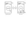
- FIG. 1 is a diagram showing the hardware configuration of a mobile device and an electronic musical instrument according to one embodiment
- FIG. 6 is a flow chart showing processing in a print mode in one embodiment.
- FIG. 10 is a diagram showing an example of a recording user interface (before an instruction to start recording);
- FIG. 10 is a diagram showing an example of a recording user interface (after instructing to start recording);
- FIG. 10 illustrates an example of a selection user interface;
- 4 is a flow chart showing processing in a print mode (the part following FIG. 3) in one embodiment.
- 4 is a flow chart showing AI quantization processing in one embodiment.
- FIG. 10 is a diagram showing an example of a beat correction user interface (before instruction for correction).
- FIG. 10 is a diagram showing an example of a beat correction user interface (before instruction for correction).
- FIG. 4 is a diagram for explaining an example of sound generation control data;
- FIG. 4 is a flow chart showing data correction processing in one embodiment.
- FIG. 10 is a diagram for explaining an example of correcting timing information;
- FIG. 10 is a diagram for explaining a comparison of sound generation control data before and after change;
- 4 is a flowchart illustrating MIDI quantization processing in one embodiment.
- FIG. 10 is a diagram showing an example of a quantize setting user interface; 4 is a flow chart showing delay offset processing in one embodiment.
- FIG. 10 is a diagram showing an example of an offset setting user interface;
- FIG. 10 is a diagram for comparing and explaining sound generation control data before and after a delay offset;
- FIG. 10 is a diagram for comparing and explaining sound generation control data before and after a delay offset;
- 4 is a flowchart showing data reproduction processing in one embodiment.
- FIG. 10 is
- the portable device 10 can record a performance on the electronic musical instrument 80 and reproduce the recorded performance on the electronic musical instrument 80 . In this reproduction, it is possible to select either to reproduce the recorded performance as it is or to reproduce at a speed according to the user's motion (for example, the motion of swinging the portable device 10 like a baton). .
- the portable device 10 can generate data corresponding to the recorded performance and modify the data so that it can be used in any of the above reproductions. Specific processing for realizing each of these functions will be described later.
- FIG. 2 is a diagram showing the hardware configuration of the portable device and the electronic musical instrument according to one embodiment.
- Portable device 10 includes control unit 110 , storage unit 120 , display unit 130 , operation unit 140 , sensor unit 150 , speaker 170 , communication unit 180 and interface 190 .
- the mobile device 10 is not limited to including all of these components, and may include other components such as a camera and a position detection unit.
- the control unit 110 is an example of a computer including a processor such as a CPU (Central Processing Unit) and a storage device such as a RAM.
- the control unit 110 executes a program 121 stored in the storage unit 120 using a CPU (processor), and causes the portable device 10 to implement functions for executing various processes described later.
- a processor such as a CPU (Central Processing Unit)
- a storage device such as a RAM.
- the control unit 110 executes a program 121 stored in the storage unit 120 using a CPU (processor), and causes the portable device 10 to implement functions for executing various processes described later.
- the data stored in the storage unit 120 includes performance record data 123, for example.
- the performance recording data 123 includes various data related to the performance, such as metadata such as the name of the music played and data related to the sound of the performance.
- the data on the performance sound includes sound generation control data 125 that defines the timing information of the sound generated by the performance.
- the sound generation control data 125 is data described in a predetermined format, for example, data described in MIDI format.
- the pronunciation timing information is information indicating the timing at which the sound is generated, and is indicated by information such as note-on, note-off, delta time, and tempo, for example.
- the sound control data 125 also includes other information corresponding to sound, such as pitch (note number).
- the display unit 130 is a display having a display area for displaying various screens under the control of the control unit 110.
- the displayed screen includes a plurality of user interfaces, which will be described later.
- the operation unit 140 is an operation device that outputs a signal to the control unit 110 according to a user's operation.
- operation unit 140 is a touch sensor arranged on the surface of display unit 130 . Therefore, the display unit 130 and the operation unit 140 are used as a touch panel by mutual functions.
- the operation unit 140 may include switches and the like arranged on the housing of the mobile device 10 .
- the sensor unit 150 outputs a signal corresponding to the movement of the mobile device 10 to the control unit 110 .
- the sensor unit 150 includes, for example, an acceleration sensor, a gyro sensor, etc., and measures the movement of the mobile device 10 .
- the speaker 170 generates sound by amplifying and outputting the sound waveform signal supplied from the control unit 110 .
- the communication unit 180 is a wireless communication module for connecting to the network NW under the control of the control unit 110 and communicating with other devices such as the data management server 90 connected to the network NW.
- the interface 190 includes a communication module for communicating with other devices such as the electronic musical instrument 80 by infrared communication or short-range wireless communication.
- the interface 190 is used for communication without going through the network NW.
- Interface 190 may include modules that provide wired rather than wireless communication.
- Electronic musical instrument 80 is an electronic keyboard device such as an electronic piano, and includes performance operators 810 , tone generator section 830 , speaker 870 and interface 890 , as described above.
- the performance operator 810 includes a plurality of keys, and outputs a signal to the tone generator section 830 according to the operation of each key.
- Interface 890 includes a communication module for communicating wirelessly or by wire with external devices. In this example, the interface 890 connects with the interface 190 of the portable device 10 by short-range wireless communication to transmit and receive data in a predetermined format (MIDI format in this example).
- the sound source unit 830 includes a DSP (Digital Signal Processor) and generates a sound waveform signal according to the pronunciation instruction signal.
- the sounding instruction signal corresponds to the signal output from performance operator 810 and the data transmitted from portable device 10 via interface 890 .
- the tone generator section 830 converts the sound generation instruction signal corresponding to the signal output from the performance operator 810 into data in MIDI format and outputs the data to the interface 890 .
- the electronic musical instrument 80 can transmit data corresponding to the operation of the performance operator 810 (hereinafter sometimes referred to as performance information) to the portable device 10 .
- FIG. 3 is a flow chart showing processing in a recording mode in one embodiment.
- FIG. 4 is a diagram showing an example of the recording user interface (before instructing to start recording).
- FIG. 5 is a diagram showing an example of the recording user interface (after instructing recording).
- the control unit 110 provides the user with a recording user interface (recording UI) by displaying a screen described below on the display unit 130 (step S101).
- the recording user interface (hereinafter sometimes referred to as interface RD) shown in FIG. 4 is a display example before the start of performance recording is instructed.
- the interface RD includes an area TS for setting the recording tempo (hereinafter sometimes referred to as recording tempo), an area RT for displaying the recording time, and a record button RB for instructing start and end of recording. .
- the control unit 110 waits until an instruction to start recording the performance is input (step S103; No).
- an instruction to start recording is input to the portable device 10 by operating the record button RB shown in FIG. 4 (step S103; Yes)
- the control unit 110 displays the record button RB as shown in FIG.
- beats are provided to the user (step S105).
- Providing beats is realized by, for example, generating a metronome sound from the portable device 10 .
- a metronome sound is generated corresponding to each beat specified at intervals determined by the recording tempo. For example, if the recording tempo is 120, a metronome sound will be generated with a beat length of 500 milliseconds.
- the mobile device 10 may provide beats to the user not only by sound but also by light, vibration, or the like.
- the control unit 110 records the sound generation control data 125 in the storage unit 120 based on the performance information provided from the electronic musical instrument 80 (step S107) until an instruction to end recording is input (step S109; No). At this time, beats are still provided to the user.
- the control section 110 ends the beat provision (step S111). Subsequently, the control unit 110 provides a selection user interface (selection UI) by displaying a screen described below on the display unit 130 (step S113).
- the control unit 110 may terminate once the recording of the sound generation control data 125 is completed according to the user's instruction.
- the control unit 110 may provide a selection user interface according to a user's instruction, and may further provide a user interface for designating the pronunciation control data 125 to be processed. Data other than the sound generation control data 125 recorded in the recording mode may be specified as the object of processing.
- the interface SD includes change selection buttons AB, MB, DB corresponding to each change method.
- AI quantize detects the beat position from the pronunciation control data 125, and corrects the timing information according to the relationship between the beat position specified from the original pronunciation control data 125 and the detected beat position. This is the process of changing the control data 125 .
- AI Artificial Intelligence
- MIDI quantize is a process of changing the sound generation control data 125 so as to correct the timing information according to the specified resolution.
- “Delay offset” is processing for changing the sound generation control data 125 so as to offset timing information corresponding to a plurality of sounds.
- the interface SD includes a save button B1 for saving the sound control data 125, a delete button B2 for discarding the sound control data 125, and a play button PB for playing back the sound control data 125.
- the play button PB When the play button PB is operated, the sound control data 125 is read and the sound indicated by the sound control data 125 is reproduced. This sound may be generated by the portable device 10 or may be generated by the electronic musical instrument 80 .
- the portable device 10 may transmit a sound generation instruction signal to the electronic musical instrument 80 .
- a playback position is indicated by a playback marker PM. The user can change the playback position in the sound generation control data 125 by changing the position of the playback marker PM.
- FIG. 7 is a flow chart showing processing in the recording mode (the part following FIG. 3) in one embodiment.
- Control unit 110 waits for an instruction input from the user to interface SD (step S201; No, S203; No, S205; No, S207; No, S209; No).
- a state in which the control unit 110 waits for an instruction in this manner is referred to as an instruction standby state.
- step S201 When an AI quantize instruction is input by operating the change selection button AB (step S201; Yes), the control unit 110 executes the AI quantize process (step S300) and returns to the instruction standby state. AI quantize processing will be described later.
- step S203 When a MIDI quantization instruction is input by operating the change selection button MB (step S203; Yes), the control unit 110 executes the MIDI quantization process (step S400) and returns to the instruction waiting state. MIDI quantize processing will be described later.
- step S205 When the change selection button DB is operated to input a delay offset instruction (step S205; Yes), the control unit 110 executes the delay offset process (step S500) and returns to the instruction waiting state.
- the delay offset processing will be described later.
- step S207 When the save button B1 is operated to input a data save instruction (step S207; Yes), the control unit 110 saves the sound generation control data 125 (step S211), and ends the recording mode processing. .
- the delete button B2 is operated to input an instruction to discard the data (step S209; Yes)
- the control unit 110 discards the sound generation control data 125 (step S213) and terminates the recording mode processing. .
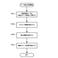
- FIG. 8 is a flowchart showing AI quantization processing in one embodiment.
- the control unit 110 converts the sound generation control data 125 into audio data (step S301).
- the audio data is data in which the sounding according to the timing information defined in the sounding control data 125 is indicated by a sound waveform signal. This sound waveform signal may be generated by the portable device 10 or may be generated by the electronic musical instrument 80 and received by the portable device 10 .
- Control unit 110 detects beats based on the audio data (step S303).
- Beats can be detected based on changes in the amplitude of the sound waveform signal.
- AI technology is used for beat detection.
- beat positions can be obtained from the trained model.
- a specific method for detecting beats is not limited to the case of using AI technology, and known beat detection methods can be applied.
- Beat detection is not limited to audio data, and may be performed on the pronunciation control data 125 .
- the control unit 110 provides a beat correction interface (beat correction UI: first user interface) by displaying a screen described below on the display unit 130 (step S305).
- the control unit 110 waits until an instruction to correct the beat position or an instruction to perform data correction processing is input to the beat correction interface (step S311; No, S321; No).
- the control section 110 corrects the beat position (step S313) and waits again (step S311; No, S321; No).
- the control unit 110 executes the data correction process (step S330) and ends the AI quantize process.
- Data correction processing may be instructed without inputting an instruction to correct the beat position. In this case, data correction processing is executed using the detected beat position as it is.
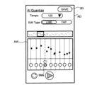
- FIG. 9 is a diagram showing an example of the beat correction user interface (before the correction instruction).
- FIG. 10 is a diagram showing an example of the beat correction user interface (before instructing correction).
- a beat correction interface (hereinafter sometimes referred to as an interface AD) includes an area TS for setting an average tempo, a line button LB and a tap button TB for setting a beat position editing method, a play button PB, and a redetection button. QB, and save button B3.
- the tempo (recording tempo) when the sound generation control data 125 was recorded is displayed as an initial value. Normally, there is no need to change the initial value, but it may be changed.
- the interface AD described in FIGS. 9 and 10 is shown as an editing method when the line button LB is operated.
- the interface AD further includes an entire area AA showing the pronunciation specified in the pronunciation control data 125 in the range of the entire song, and an enlarged area AW showing an enlarged range specified by the selection window SW.
- the vertical axis indicates pitch
- the horizontal axis indicates time
- each pronunciation is indicated by a note mark NM.
- the position of the selection window SW can be changed in the entire area AA, and by changing the length in the horizontal axis direction, it is possible to change the enlargement ratio in the time axis direction when displayed in the enlarged area AW.
- the position of the beat detected from the sound generation control data 125 is indicated by the beat position line BL in the enlarged area AW.
- a circular beat marker BM is displayed below the beat position line BL.
- the beat marker BM is used when the user corrects the beat position.
- the beat markers BMs specified by the user as change targets are displayed in a form distinguishable from other beat markers BM. At this time, as shown in FIG. 9, the display form of the beat position line BL corresponding to the beat marker BMs may also change.
- Shifting the beat marker BMs specified by the user in FIG. 9 to the left as shown in FIG. 10 corresponds to inputting a beat position correction instruction (FIG. 8, step S311; Yes).
- the control unit 110 corrects the position of the beat corresponding to the beat marker BMs to the position of the beat marker BMs after movement ( FIG. 8 , step S313).
- Such correction is performed when the detected beat position and the beat position assumed by the user are different.
- the control unit 110 plays back sounds corresponding to the sound generation control data 125 within the range displayed in the enlarged area AW.
- a sound indicating the beat (metronome sound) may be generated at the position of the detected beat. In this manner, the relationship between the detected beat position or the corrected beat position and the pronunciation timing may be recognized by the sound.
- control unit 110 When the redetection button QB is operated, the control unit 110 returns to step S303 and executes beat detection. At this time, if there is a beat whose position has been corrected by the user, the control unit 110 may fix the position of the corrected beat and execute the beat detection process.
- FIG. 11 is a diagram for explaining an example of sound generation control data.
- FIG. 11 shows the relationship between the timing information of the sound generation control data 125 and the positions of the beats at "during recording", “during beat detection", and “during beat correction”.
- "When recording” indicates the sound generation control data 125 when recorded in the recording mode.
- "At time of beat detection” indicates the sound generation control data 125 when beats are detected in the AI quantize process.
- “At the time of beat correction” indicates the sound generation control data 125 when the detected beat position is corrected by the user.
- the horizontal axis indicates time t.
- the sound NT indicates the pronunciation position corresponding to the timing information. Since the sound generation control data 125 is not changed during the period from the time of recording to the time of beat correction, the position of the note NT does not change.
- the beat positions SBT1, SBT2, . . . indicate the beat positions during recording. Therefore, both beats have the same length.
- the positions of the detected beats are not necessarily evenly spaced. Therefore, in the example of FIG. 11, there are beats whose positions (timings) are shifted between recording and beat detection.
- the beat after the position of the beat is corrected by moving the beat marker BMs on the interface AD is shown.
- FIG. 11 shows an example in which the beat positions DBT4 and DBT6 are corrected. Correction of the beat position DBT4 corresponds to the example shown in FIG. Correction of the beat position DBT6 is correction for aligning the ornament NTs with the beat position. The purpose of such correction is related to data reproduction processing, and will be described later.
- step S330 Operation of the save button B3 on the interface AD corresponds to input of an instruction for data correction processing (step S321; Yes). Therefore, when save button B3 is operated, control unit 110 executes data correction processing (step S330). At this time, the portable device 10 may associate the sound generation control data 125 or the audio data with the corrected beat position data and transmit the data to the data management server 90 .
- the data management server 90 registers the data received from the mobile device 10 in the database in the storage unit 920 .
- the data management server 90 can execute processing using data registered in the database. For example, such user-corrected data is used to improve the accuracy of beat detection technology, or to improve the accuracy of AI technology in beat detection (such as updating a learned model using registered data as teacher data). can also
- FIG. 12 is a flowchart showing data correction processing in one embodiment.
- the control unit 110 divides the sound generation control data 125 at the beat positions DBT1, DBT2, . (step S331).
- the control unit 110 expands or contracts each of the plurality of divided data sections to a length corresponding to the section length corresponding to the average tempo (the length of one beat corresponding to the average tempo).
- the position of each pronunciation included in each data section, that is, the timing information is corrected (step S333).
- the control unit 110 adds correction information according to the correction amount of the timing information to each data section (step S335), and combines the plurality of data sections to which the correction information with the corrected timing information is added (step S337). .
- Data correction processing will be described in more detail with reference to FIGS. 13 and 14.
- FIG. 13 and 14 Data correction processing will be described in more detail with reference to FIGS. 13 and 14.
- FIG. 13 is a diagram for explaining an example of correcting timing information.
- FIG. 13 shows an example of correcting the timing information in the data section between beat position DBT4 and beat position DBT5 among a plurality of data sections.
- "After division” indicates the sound generation control data 125 in the data section before correction.
- "Corrected” indicates the sound generation control data 125 after correcting the timing information.
- the data section length before correction corresponds to tempo "110".
- the average tempo is set to "120". Therefore, the data section length is changed to a length corresponding to the tempo "120". Since the length of the data section is multiplied by "110/120", the pronunciation timing information included in this data section is corrected to a position multiplied by "110/120” based on the beginning of the beat (beat position DBT4). . Thus, the correction amount is "110/120".
- the correction information is added as a tempo value "110" corresponding to the original data section length as a value corresponding to the correction amount at a position corresponding to the beat position DBT4. It may be added as a relative value to the average tempo as "110/120". If the data is in MIDI format, it is added as tempo change information.
- FIG. 14 is a diagram for comparing and explaining sound generation control data before and after change.
- FIG. 14 shows the relationship between the timing information of the sound generation control data 125 and the positions of beats "during recording" and "after combining".
- "When recording” indicates the sound generation control data 125 when recorded in the recording mode, that is, before the timing information is changed by the AI quantize process.
- “After combining” indicates the sound generation control data 125 after combining the data sections to which the timing information has been corrected by AI quantization processing and the correction information has been added, that is, after the timing information has been changed. As shown in FIG.
- the AI quantize process aligns the detected beats (or further corrected beats) to a predetermined tempo (average tempo in this example) so that the length of the original beat can be identified.
- the sound generation control data 125 is changed by adding correction information corresponding to the correction amount (in this example, the tempo value corresponding to the original beat length).
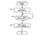
- FIG. 15 is a flowchart showing MIDI quantization processing in one embodiment.
- the control unit 110 provides a quantization setting user interface (quantization processing setting UI) by displaying a screen described below on the display unit 130 (step S401), and waits until an instruction for quantization processing is input ( Step S403; No).
- a quantize process instruction is input (step S403; Yes)
- the control unit 110 executes the quantize process according to the setting (step S405), and ends the MIDI quantize process.
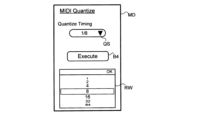
- FIG. 16 is a diagram showing an example of a quantize setting user interface.
- the quantization setting user interface (hereinafter sometimes referred to as interface MD) includes an area QS for setting the resolution of quantization and an execution button B4 for inputting instructions for quantization processing.
- the interface MD contains a window RW for selecting the resolution to be set. If the quantization resolution is "1/8", the timing information is corrected so that the timing is aligned in units of eighth notes.
- This processing is similar to general quantization processing.
- the interface MD may include an area for setting conditions for sounds that are not subject to quantization. A sound not to be quantized may, for example, be moved by the same amount as the nearest quantized sound. Sounds excluded from the quantization process may be, for example, sounds whose length is less than half the resolution, or sounds whose velocity (volume) is lower than a predetermined value. Conversely, the interface MD may include an area in which sounds to be quantized can be specified.
- MIDI quantization process when the rhythm fluctuates during the recording of the sound generation control data 125, it is possible to remove the fluctuation of the rhythm of the sound generation contained in the sound generation control data 125 and align it with the position of the beat. can. This is particularly effective for songs in which rhythm is important, such as dance music.
- rhythm is important, such as dance music.
- FIG. 17 is a flowchart showing delay offset processing in one embodiment.
- the control unit 110 provides an offset setting user interface (offset setting UI: second user interface) by displaying a screen described below on the display unit 130 (step S501), and an instruction for offset processing is input. (Step S503; No).
- offset processing instruction is input (step S503; Yes)
- the control unit 110 executes the offset processing according to the setting (step S505), and ends the delay offset processing.
- FIG. 18 is a diagram showing an example of an offset setting user interface.
- the offset setting user interface (hereinafter sometimes referred to as interface DD) includes an area OS for setting an offset amount and an execution button B5 for inputting an offset processing instruction.
- interface DD includes window RW for selecting the amount of offset to be set. If the offset amount is "30", the sound generation control data 125 is changed by correcting the timing information so as to delay the entire timing by 30 ticks.
- the interface DD may have an area for specifying the sound to be processed.
- the timing information may be corrected for the target sound and a plurality of sounds following the target sound. If the sound to be processed is not specified, the first sound in the pronunciation control data 125 may be specified as the sound to be processed. Two examples of the case where the sound to be processed is designated and corrected will be described with reference to FIGS. 19 and 20.
- FIG. 19 Two examples of the case where the sound to be processed is designated and corrected will be described with reference to FIGS. 19 and 20.
- 19 and 20 are diagrams for comparing and explaining the sound generation control data before and after the delay offset.
- 19 and 20 both show the relationship between the timing information of the sound generation control data 125 and the position of beats "at the time of beat detection” and "after offset”.
- "At time of beat detection” indicates the sound generation control data 125 when beats are detected in the AI quantize process.
- "After offset” indicates the pronunciation control data 125 after the ornamental tone NTs has been designated as the sound to be processed and the offset processing has been performed. Since it is assumed that the grace note is aligned with the beat position by the offset processing, it is assumed that the offset amount is specified so as to move the grace note NTs to the beat position DBT6.
- the timing information is similarly corrected so that the grace note NTs moves to the beat position DBT6.
- the timing information is corrected such that the further away from the ornamental tone NTs, the smaller the offset amount.
- the timing information may be corrected only for sounds within a predetermined number of beats (for example, within four beats) from the grace note NTs.
- Portable device 10 outputs a sound generation instruction signal based on sound generation control data 125 to electronic musical instrument 80 so that sound waveform signal is reproduced in sound source unit 830 .
- modes for reproducing the sound generation control data 125 include an auto mode and a control mode.
- the sound generation control data 125 is read out at a predetermined tempo, and the tempo is corrected using the correction information set corresponding to each beat, thereby substantially correcting the position of the beat and reproducing the sound waveform.
- This mode realizes signal playback and reproduces the performance sound when the data was recorded. If the correction information is not used when reading the sound generation control data 125, as shown in FIG. By changing the reading speed, it is possible to reproduce the performance sound when the data was recorded.
- the sounding control data 125 is read at a predetermined tempo because correction information is not included.
- the ornaments may be desirable to correct the ornaments so that they match the beat position. Ornaments are often positioned slightly before the position of the beat. In such a case, it is desirable that the ornamented tone present at the position of the beat and the ornamental note present before it are reproduced continuously.
- the ornament sounds are reproduced at an early timing, and the ornament sound and the ornamented sound are reproduced with a large gap between them. situation arises. Assuming such a case, by correcting the timing information so that the ornament is positioned at the position of the beat, it is possible to reproduce the ornament and the ornamented tone as one unit without separating them. can.
- FIG. 21 is a flowchart showing data reproduction processing in one embodiment.
- the control unit 110 provides a playback user interface (playback UI) by displaying a screen described below on the display unit 130 (step S801), and waits until an instruction to start data playback is input (step S803). ; No).
- playback UI playback user interface
- control unit 110 controls sound generation by reproducing sound generation control data 125 until an instruction to stop data reproduction is input (step S821; No). Execute the process.
- the control unit 110 executes sound generation control processing in the auto mode (step S813).
- the auto mode is not selected, that is, when the control mode is selected as the reproduction mode (step S813; No)
- sound generation control processing in the control mode is executed (step S815).
- control unit 110 terminates the data reproduction process.
- FIG. 22 is a diagram showing an example of a playback user interface.
- the playback user interface (hereinafter sometimes referred to as interface PD) includes a switch button PMB for switching between auto mode and control mode.
- the switch button PMB includes an image that indicates whether it is operating in auto mode or in control mode. It may be selected so that the mode is switched each time the switching button PMB is operated, or one of the modes (for example, the control mode) is switched while the switching button PMB is being operated (while the switching button PMB is being touched). It may be selected.
- a stop button B6 When operating in auto mode, a stop button B6 is displayed to stop the progress of the song. In the control mode, if the user stops swinging the mobile device 10, the song will stop progressing. Therefore, the stop button B6 does not have to be displayed as shown in FIG. Operating the stop button B6 corresponds to inputting an instruction to stop data reproduction (step S821; Yes). good.
- the sound generation control data 125 recorded according to the performance can be changed to data that can be used in a plurality of different reproduction methods such as the auto mode and the control mode. can be done. It is also possible to change the sound generation control data 125 by selecting an appropriate change method depending on the song.
- correction information was added for each beat, but may be added for every two or more beats, or may be added for each sound. .
- the interface SD allows selection of a process of analyzing an image of a musical score, extracting bar lines, musical notes, performance symbols, etc., and correcting the timing information of the sound generation control data 125 based on the extracted information. good too.
- a data modification method of the present disclosure provides a selection user interface for selecting a modification method to be applied to pronunciation control data defining pronunciation timing information from a plurality of modification methods including a first modification method and a second modification method. and correcting the timing information when applying the first change method is selected, and providing correction information corresponding to the amount of correction of the timing information in the data section for a predetermined data section. modifying the pronunciation control data by adding, and correcting the timing information based on beat positions according to a predetermined tempo when applying the second modification method is selected; modifying the pronunciation control data.
- the data change method of the present disclosure may provide a recording user interface for setting a tempo and instructing performance recording, and when the start of performance recording is instructed, beat information is recorded at the set tempo.
- the sound control data may be recorded based on performance information input while the beat information is being provided, and when an instruction to stop the performance recording is given, the recorded sound control data may be
- a selection user interface may be provided for selecting the modification method to be applied to.
- the plurality of modification methods may further include a third modification method, and when applying the third modification method is selected, specified predetermined pronunciation timing information and timing information of a plurality of pronunciations following the predetermined pronunciation may be changed to change the pronunciation control data.
- the data modification method of the present disclosure may further include providing beat information at a predetermined tempo, and recording the sound generation control data based on performance information input while providing the beat information. , the correction information may be added corresponding to the timing of providing the beat information.
- Detecting the positions of the plurality of beats may include converting the pronunciation control data into audio data and detecting the positions of the plurality of beats based on the audio data.
- the data modification method of the present disclosure may further include providing a first user interface for correcting the detected beat position, wherein modifying the pronunciation control data comprises: and correcting the timing information based on the relationship between the positions of the plurality of beats and the set tempo after being corrected via the method.
- the data modification method of the present disclosure provides a recording user interface for instructing recording of a performance, and when an instruction to start recording the performance is given, the method defines pronunciation timing information based on input performance information.
- a change method to be applied to the recorded sound generation control data is selected from a plurality of change methods including a first change method and a second change method.
- the present disclosure can also be used as a program for causing a computer to execute the data modification method or the data reproduction method, and can be used as a data modification device for executing the data modification method and a data reproduction device for executing the data reproduction method.
- a program for causing a computer to execute the data modification method or the data reproduction method can be used as a data modification device for executing the data modification method and a data reproduction device for executing the data reproduction method.
- at least part of the portable device 10 can function as a data modification device or a data reproduction device.
- 10 portable device, 110: control unit, 120: storage unit, 121: program, 123: performance recording data, 125: sound generation control data, 130: display unit, 140: operation unit, 150: sensor unit, 170: speaker, 180: communication unit, 190: interface, 80: electronic musical instrument, 810: performance operator, 830: sound source unit, 870: speaker, 890: interface, 90: data management server, 910: control unit, 920: storage unit, 980 : Communications department
Landscapes
- Physics & Mathematics (AREA)
- Engineering & Computer Science (AREA)
- Acoustics & Sound (AREA)
- Multimedia (AREA)
- Electrophonic Musical Instruments (AREA)
Abstract
In the data modification method according to one embodiment: a selection user interface is provided for selecting, from among a plurality of modification methods including a first modification method and a second modification method, a modification method to be applied to sound control data that defines sound timing information; when the application of the first modification is selected, the sound control data is modified by correcting the timing information and adding, to a specific data segment, correction information based on a correction amount of the timing information in said specific data segment; and when the application of the second modification method is applied, the sound control data is modified by correcting the timing information on the basis of the position of a beat based on a specific tempo.
Description
本開示は、発音を制御するためのデータを変更する方法に関する。
The present disclosure relates to a method of changing data for controlling pronunciation.
MIDIデータ等の発音を制御するデータ(以下、発音制御データという)に基づいて、自動演奏をすることによって音波形信号を生成する技術が存在する。一般的に、発音制御データには自動演奏の速度(テンポ)が定義されている。すなわち、発音制御データを再生すると、発音制御データに記録された演奏音が再現される。特許文献1、2、3に示すように、ユーザの動きに応じてテンポを制御する技術も開発されている。ユーザによるテンポの制御は、例えば、ユーザが手に持った携帯装置を指揮棒のようにして振ることによって実現される。したがって、発音制御データに記録された演奏音がそのまま再現されるのではなく、ユーザの動作に応じて再生速度が変化した演奏音が再現される。
There is a technique for generating a sound waveform signal by performing automatic performance based on data for controlling sound production such as MIDI data (hereinafter referred to as sound production control data). In general, the sound generation control data defines the speed (tempo) of automatic performance. That is, when the sound generation control data is reproduced, the performance sound recorded in the sound generation control data is reproduced. As shown in Patent Documents 1, 2, and 3, techniques have also been developed for controlling the tempo according to the movement of the user. The tempo control by the user is realized, for example, by swinging the portable device held in the user's hand like a baton. Therefore, the performance sound recorded in the sound generation control data is not reproduced as it is, but the performance sound is reproduced with the reproduction speed changed according to the user's operation.
ユーザの動作によるテンポ制御での自動演奏と、予め決められたテンポ制御での自動演奏と、のいずれか一方が選択されて、選択された自動演奏が実現されることもある。このような場合、ユーザの動作によるテンポ制御が可能な発音制御データと、予め決められたテンポ制御が可能な発音制御データとは、共通のデータとして生成されることが望ましい。予めテンポが決められた発音制御データは一般的に存在するため、予めテンポが決められた発音制御データを、ユーザによるテンポ制御が可能な発音制御データとしても用いることができるように変更することが望まれる。
Either automatic performance under tempo control by the user's actions or automatic performance under predetermined tempo control may be selected, and the selected automatic performance may be realized. In such a case, it is desirable that the sound generation control data capable of controlling the tempo by the user's motion and the sound generation control data capable of controlling the predetermined tempo are generated as common data. Since sounding control data with a predetermined tempo generally exists, it is possible to change the sounding control data with a predetermined tempo so that it can also be used as sounding control data that allows the user to control the tempo. desired.
本開示の目的の一つは、演奏音が記録された発音制御データを、ユーザの動作によるテンポ制御を可能とするデータに容易に変更することにある。
One of the purposes of the present disclosure is to easily change sound generation control data in which performance sounds are recorded into data that enables tempo control by user's actions.
本開示の一実施形態によれば、発音のタイミング情報を定義する発音制御データに対して適用する変更方法を、第1変更方法および第2変更方法を含む複数の変更方法から選択するための選択ユーザインターフェースを提供し、前記第1変更方法を適用することが選択された場合に、前記タイミング情報を補正し、所定のデータ区間に対して当該データ区間における前記タイミング情報の補正量に応じた補正情報を追加することによって、前記発音制御データを変更し、前記第2変更方法を適用することが選択された場合に、所定のテンポに応じた拍の位置に基づいて前記タイミング情報を補正することによって、前記発音制御データを変更すること、を含むデータ変更方法が提供される。
According to an embodiment of the present disclosure, a selection for selecting a modification method to be applied to pronunciation control data defining pronunciation timing information from a plurality of modification methods including a first modification method and a second modification method providing a user interface, correcting the timing information when applying the first change method is selected, and correcting the timing information for a predetermined data section according to the correction amount of the timing information in the data section. modifying the pronunciation control data by adding information to correct the timing information based on beat positions according to a predetermined tempo when applying the second modification method is selected; provides a data modification method comprising: modifying the pronunciation control data.
本開示の一実施形態によれば、所定のテンポで記録された発音のタイミング情報を定義する発音制御データに基づいて、複数の拍の位置を検出し、複数の前記拍の位置と前記テンポとの関係に基づいて前記タイミング情報を補正し、所定のデータ区間に対して当該データ区間における前記タイミング情報の補正量に応じた補正情報を追加することによって、前記発音制御データを変更すること、を含むデータ変更方法が提供される。
According to an embodiment of the present disclosure, based on pronunciation control data defining pronunciation timing information recorded at a predetermined tempo, positions of a plurality of beats are detected, and positions of the plurality of beats and the tempo are detected. modifying the sound generation control data by correcting the timing information based on the relationship of A data modification method is provided that includes:
本開示の一実施形態によれば、演奏音が記録された発音制御データを、ユーザの動作によるテンポ制御を可能とするデータに容易に変更することができる。
According to one embodiment of the present disclosure, it is possible to easily change sound generation control data in which performance sounds are recorded into data that enables tempo control by user's actions.
以下、本発明の一実施形態について、図面を参照しながら詳細に説明する。以下に示す実施形態は一例であって、本発明はこれらの実施形態に限定して解釈されるものではない。本実施形態で参照する図面において、同一部分または同様な機能を有する部分には同一の符号または類似の符号(数字の後にA、Bなど付しただけの符号)を付し、その繰り返しの説明は省略する場合がある。
Hereinafter, one embodiment of the present invention will be described in detail with reference to the drawings. The embodiments shown below are examples, and the present invention should not be construed as being limited to these embodiments. In the drawings referred to in this embodiment, the same parts or parts having similar functions are denoted by the same reference numerals or similar reference numerals (reference numerals followed by A, B, etc.). May be omitted.
[1.全体構成]
図1は、一実施形態におけるシステム構成を示す図である。図1に示すシステムは、インターネット等のネットワークNWを介して接続された携帯装置10およびデータ管理サーバ90を含み、さらに携帯装置10に接続された電子楽器80を含む。電子楽器80の機能の少なくとも一部が携帯装置10に含まれていてもよい。携帯装置10は、この例では、スマートフォンなどの携帯可能な通信端末である。電子楽器80は、この例では、電子ピアノなどの電子鍵盤装置である。 [1. overall structure]
FIG. 1 is a diagram showing a system configuration in one embodiment. The system shown in FIG. 1 includes amobile device 10 and a data management server 90 connected via a network NW such as the Internet, and further includes an electronic musical instrument 80 connected to the mobile device 10 . At least part of the functions of the electronic musical instrument 80 may be included in the portable device 10 . The mobile device 10 is a portable communication terminal such as a smart phone in this example. The electronic musical instrument 80 is an electronic keyboard device such as an electronic piano in this example.
図1は、一実施形態におけるシステム構成を示す図である。図1に示すシステムは、インターネット等のネットワークNWを介して接続された携帯装置10およびデータ管理サーバ90を含み、さらに携帯装置10に接続された電子楽器80を含む。電子楽器80の機能の少なくとも一部が携帯装置10に含まれていてもよい。携帯装置10は、この例では、スマートフォンなどの携帯可能な通信端末である。電子楽器80は、この例では、電子ピアノなどの電子鍵盤装置である。 [1. overall structure]
FIG. 1 is a diagram showing a system configuration in one embodiment. The system shown in FIG. 1 includes a
携帯装置10は、電子楽器80に対する演奏を記録すること、記録した演奏を電子楽器80において再生させることができる。この再生においては、記録した演奏をそのまま再生すること、およびユーザの動作(例えば携帯装置10を指揮棒のようにして振る動作)にしたがった速度で再生することのいずれかを選択することができる。携帯装置10は、記録した演奏に対応するデータを生成し、上記のいずれかの再生においても用いることができるようにデータを変更することができる。このような各機能を実現するための具体的な処理については、後述する。
The portable device 10 can record a performance on the electronic musical instrument 80 and reproduce the recorded performance on the electronic musical instrument 80 . In this reproduction, it is possible to select either to reproduce the recorded performance as it is or to reproduce at a speed according to the user's motion (for example, the motion of swinging the portable device 10 like a baton). . The portable device 10 can generate data corresponding to the recorded performance and modify the data so that it can be used in any of the above reproductions. Specific processing for realizing each of these functions will be described later.
データ管理サーバ90は、制御部910、記憶部920および通信部980を含む。制御部910は、CPU、RAMおよびROMを含む。制御部910は、記憶部920に記憶されたプログラムを、CPUを用いて実行することによって、プログラムに記述された命令にしたがった処理を行う。記憶部920は、不揮発性メモリ、ハードディスクドライブなどの記憶装置を含む。通信部980は、ネットワークNWに接続して、他の装置と通信するための通信モジュールを含む。データ管理サーバ90は、携帯装置10において生成されるデータの一部を記憶部920において保存し、そのデータを利用した処理を実行する。具体的な処理の内容は後述する。一実施形態において、データ管理サーバ90は、存在しなくてもよい。
The data management server 90 includes a control section 910 , a storage section 920 and a communication section 980 . Control unit 910 includes a CPU, RAM and ROM. Control unit 910 executes a program stored in storage unit 920 using the CPU, thereby performing processing according to instructions described in the program. Storage unit 920 includes a storage device such as a nonvolatile memory and a hard disk drive. Communication unit 980 includes a communication module for connecting to network NW and communicating with other devices. The data management server 90 stores part of the data generated in the portable device 10 in the storage unit 920 and executes processing using the data. The specific contents of the processing will be described later. In one embodiment, data management server 90 may not exist.
[2-1.携帯装置の構成]
図2は、一実施形態における携帯装置および電子楽器のハードウェア構成を示す図である。携帯装置10は、制御部110、記憶部120、表示部130、操作部140、センサ部150、スピーカ170、通信部180およびインターフェース190を含む。携帯装置10は、これらの構成を全て含むものに限定されず、カメラ、位置検出部などさらに別の構成を含んでいてもよい。 [2-1. Configuration of portable device]
FIG. 2 is a diagram showing the hardware configuration of the portable device and the electronic musical instrument according to one embodiment.Portable device 10 includes control unit 110 , storage unit 120 , display unit 130 , operation unit 140 , sensor unit 150 , speaker 170 , communication unit 180 and interface 190 . The mobile device 10 is not limited to including all of these components, and may include other components such as a camera and a position detection unit.
図2は、一実施形態における携帯装置および電子楽器のハードウェア構成を示す図である。携帯装置10は、制御部110、記憶部120、表示部130、操作部140、センサ部150、スピーカ170、通信部180およびインターフェース190を含む。携帯装置10は、これらの構成を全て含むものに限定されず、カメラ、位置検出部などさらに別の構成を含んでいてもよい。 [2-1. Configuration of portable device]
FIG. 2 is a diagram showing the hardware configuration of the portable device and the electronic musical instrument according to one embodiment.
制御部110は、CPU(Central Processing Unit)などのプロセッサおよびRAM等の記憶装置を備えるコンピュータの一例である。制御部110は、記憶部120に記憶されたプログラム121を、CPU(プロセッサ)を用いて実行し、後述する様々な処理を実行するための機能を携帯装置10において実現させる。
The control unit 110 is an example of a computer including a processor such as a CPU (Central Processing Unit) and a storage device such as a RAM. The control unit 110 executes a program 121 stored in the storage unit 120 using a CPU (processor), and causes the portable device 10 to implement functions for executing various processes described later.
記憶部120は、不揮発性メモリ、ハードディスクドライブなどの記憶装置である。記憶部120は、制御部110において実行されるプログラム121およびこのプログラム121を実行するときに必要となる各種データを記憶する。プログラム121は、データ管理サーバ90または他のサーバからネットワークNW経由でダウンロードされ、記憶部120に記憶されることによって、携帯装置10にインストールされる。プログラム121は、非一過性のコンピュータに読み取り可能な記録媒体(例えば、磁気記録媒体、光記録媒体、光磁気記録媒体、半導体メモリ等)に記録した状態で提供されてもよい。この場合、携帯装置10は、この記録媒体を読み取る装置を備えていればよい。記憶部120も記録媒体の一例といえる。
The storage unit 120 is a storage device such as a non-volatile memory or hard disk drive. The storage unit 120 stores a program 121 executed by the control unit 110 and various data necessary for executing the program 121 . The program 121 is installed in the portable device 10 by being downloaded from the data management server 90 or another server via the network NW and stored in the storage unit 120 . The program 121 may be provided in a state recorded in a non-transitory computer-readable recording medium (for example, a magnetic recording medium, an optical recording medium, a magneto-optical recording medium, a semiconductor memory, etc.). In this case, the portable device 10 may be provided with a device for reading this recording medium. The storage unit 120 can also be said to be an example of a recording medium.
記憶部120に記憶されるデータは、例えば、演奏記録データ123を含む。演奏記録データ123は、演奏に関する様々なデータを含み、例えば、演奏曲の名称などのメタデータおよび演奏音に関するデータを含む。演奏音に関するデータは、演奏による発音のタイミング情報を定義する発音制御データ125を含む。発音制御データ125は、所定の形式で記述されたデータであり、例えば、MIDI形式により記述されたデータである。この場合、発音のタイミング情報は、音が発生するタイミングを示す情報であり、例えば、ノートオン、ノートオフ、デルタタイム、テンポなどの情報によって示される。発音に対応する他の情報、例えば、音高(ノートナンバ)等の情報も発音制御データ125に含まれる。
The data stored in the storage unit 120 includes performance record data 123, for example. The performance recording data 123 includes various data related to the performance, such as metadata such as the name of the music played and data related to the sound of the performance. The data on the performance sound includes sound generation control data 125 that defines the timing information of the sound generated by the performance. The sound generation control data 125 is data described in a predetermined format, for example, data described in MIDI format. In this case, the pronunciation timing information is information indicating the timing at which the sound is generated, and is indicated by information such as note-on, note-off, delta time, and tempo, for example. The sound control data 125 also includes other information corresponding to sound, such as pitch (note number).
表示部130は、制御部110の制御に応じて様々な画面を表示する表示領域を有するディスプレイである。表示される画面は、後述する複数のユーザインターフェースを含む。操作部140は、ユーザの操作に応じた信号を制御部110に出力する操作装置である。この例では、操作部140は、表示部130の表面に配置されたタッチセンサである。そのため、表示部130および操作部140は、互いの機能によってタッチパネルとして用いられる。操作部140は、携帯装置10の筐体に配置されたスイッチ等を含んでもよい。
The display unit 130 is a display having a display area for displaying various screens under the control of the control unit 110. The displayed screen includes a plurality of user interfaces, which will be described later. The operation unit 140 is an operation device that outputs a signal to the control unit 110 according to a user's operation. In this example, operation unit 140 is a touch sensor arranged on the surface of display unit 130 . Therefore, the display unit 130 and the operation unit 140 are used as a touch panel by mutual functions. The operation unit 140 may include switches and the like arranged on the housing of the mobile device 10 .
センサ部150は、携帯装置10の動きに応じた信号を制御部110に出力する。センサ部150は、例えば、加速度センサ、ジャイロセンサ等を含み、携帯装置10の動きを測定する。スピーカ170は、制御部110から供給される音波形信号を増幅して出力することによって、音を発生する。
The sensor unit 150 outputs a signal corresponding to the movement of the mobile device 10 to the control unit 110 . The sensor unit 150 includes, for example, an acceleration sensor, a gyro sensor, etc., and measures the movement of the mobile device 10 . The speaker 170 generates sound by amplifying and outputting the sound waveform signal supplied from the control unit 110 .
通信部180は、制御部110の制御により、ネットワークNWと接続して、ネットワークNWに接続されたデータ管理サーバ90など他の装置と通信をするための無線通信モジュールである。インターフェース190は、赤外線通信、近距離無線通信によって電子楽器80など他の装置と通信するための通信モジュールを含む。インターフェース190は、ネットワークNWを介さずに通信するために用いられる。インターフェース190は、無線通信ではなく有線通信をするモジュールを有していてもよい。
The communication unit 180 is a wireless communication module for connecting to the network NW under the control of the control unit 110 and communicating with other devices such as the data management server 90 connected to the network NW. The interface 190 includes a communication module for communicating with other devices such as the electronic musical instrument 80 by infrared communication or short-range wireless communication. The interface 190 is used for communication without going through the network NW. Interface 190 may include modules that provide wired rather than wireless communication.
[2-2.電子楽器の構成]
電子楽器80は、上述したように、電子ピアノなどの電子鍵盤装置であって、演奏操作子810、音源部830、スピーカ870およびインターフェース890を含む。演奏操作子810は、複数の鍵を含み、各鍵への操作に応じた信号を音源部830に出力する。インターフェース890は、無線または有線によって外部装置と通信するための通信モジュールを含む。この例では、インターフェース890は、携帯装置10のインターフェース190と短距離無線通信により接続して、所定のフォーマット(この例ではMIDI形式)のデータを送受信する。 [2-2. Configuration of Electronic Musical Instrument]
Electronicmusical instrument 80 is an electronic keyboard device such as an electronic piano, and includes performance operators 810 , tone generator section 830 , speaker 870 and interface 890 , as described above. The performance operator 810 includes a plurality of keys, and outputs a signal to the tone generator section 830 according to the operation of each key. Interface 890 includes a communication module for communicating wirelessly or by wire with external devices. In this example, the interface 890 connects with the interface 190 of the portable device 10 by short-range wireless communication to transmit and receive data in a predetermined format (MIDI format in this example).
電子楽器80は、上述したように、電子ピアノなどの電子鍵盤装置であって、演奏操作子810、音源部830、スピーカ870およびインターフェース890を含む。演奏操作子810は、複数の鍵を含み、各鍵への操作に応じた信号を音源部830に出力する。インターフェース890は、無線または有線によって外部装置と通信するための通信モジュールを含む。この例では、インターフェース890は、携帯装置10のインターフェース190と短距離無線通信により接続して、所定のフォーマット(この例ではMIDI形式)のデータを送受信する。 [2-2. Configuration of Electronic Musical Instrument]
Electronic
音源部830は、DSP(Digital Signal Processor)を含み、発音指示信号に応じて音波形信号を生成する。発音指示信号は、演奏操作子810から出力される信号およびインターフェース890を介して携帯装置10から送信されるデータに対応する。また、音源部830は、演奏操作子810から出力される信号に応じた発音指示信号を、MIDI形式のデータに変換してインターフェース890に出力する。これによって、電子楽器80は、演奏操作子810への操作に対応するデータ(以下、演奏情報という場合がある)を携帯装置10へ送信することもできる。
The sound source unit 830 includes a DSP (Digital Signal Processor) and generates a sound waveform signal according to the pronunciation instruction signal. The sounding instruction signal corresponds to the signal output from performance operator 810 and the data transmitted from portable device 10 via interface 890 . Also, the tone generator section 830 converts the sound generation instruction signal corresponding to the signal output from the performance operator 810 into data in MIDI format and outputs the data to the interface 890 . As a result, the electronic musical instrument 80 can transmit data corresponding to the operation of the performance operator 810 (hereinafter sometimes referred to as performance information) to the portable device 10 .
[3.記録モード]
続いて、電子楽器80に対する演奏を携帯装置10において記録するときの処理について説明する。このように演奏を記録する処理モードを記録モードという。携帯装置10は、記録モードを開始する指示がユーザによって入力されると、記録モードの処理を開始する。 [3. Recording mode]
Next, a description will be given of processing when a performance on the electronicmusical instrument 80 is recorded on the portable device 10. FIG. A processing mode for recording a performance in this way is called a recording mode. When the user inputs an instruction to start the recording mode, the portable device 10 starts processing in the recording mode.
続いて、電子楽器80に対する演奏を携帯装置10において記録するときの処理について説明する。このように演奏を記録する処理モードを記録モードという。携帯装置10は、記録モードを開始する指示がユーザによって入力されると、記録モードの処理を開始する。 [3. Recording mode]
Next, a description will be given of processing when a performance on the electronic
図3は、一実施形態における記録モードの処理を示すフローチャートである。図4は、記録ユーザインターフェースの例(記録開始指示前)を示す図である。図5は、記録ユーザインターフェースの例(記録指示後)を示す図である。制御部110は、以下に説明する画面を表示部130に表示することによって、記録ユーザインターフェース(記録UI)をユーザに提供する(ステップS101)。図4に示す記録ユーザインターフェース(以下、インターフェースRDという場合がある)は、演奏記録の開始が指示される前における表示例である。インターフェースRDは、記録時のテンポ(以下、記録テンポという場合がある)を設定するための領域TS、記録時間を表示する領域RT、および記録開始および記録終了を指示するための記録ボタンRBを含む。
FIG. 3 is a flow chart showing processing in a recording mode in one embodiment. FIG. 4 is a diagram showing an example of the recording user interface (before instructing to start recording). FIG. 5 is a diagram showing an example of the recording user interface (after instructing recording). The control unit 110 provides the user with a recording user interface (recording UI) by displaying a screen described below on the display unit 130 (step S101). The recording user interface (hereinafter sometimes referred to as interface RD) shown in FIG. 4 is a display example before the start of performance recording is instructed. The interface RD includes an area TS for setting the recording tempo (hereinafter sometimes referred to as recording tempo), an area RT for displaying the recording time, and a record button RB for instructing start and end of recording. .
制御部110は、演奏の記録開始の指示が入力されるまで待機する(ステップS103;No)。図4に示す記録ボタンRBが操作されることによって記録開始の指示が携帯装置10に入力される(ステップS103;Yes)と、制御部110は、図5に示すように記録ボタンRBの表示を変更し、演奏の記録を開始するために、ユーザに対する拍の提供を開始する(ステップS105)。拍の提供は、例えば、携帯装置10からメトロノーム音を発生させることによって実現される。メトロノーム音は、記録テンポにより定まる間隔で特定される各拍に対応して発生する。例えば、記録テンポが120であれば、1拍の長さ500ミリ秒でメトロノーム音が発生する。携帯装置10は、ユーザに対して音により拍を提供する場合に限らず、光、振動などによって拍を提供してもよい。
The control unit 110 waits until an instruction to start recording the performance is input (step S103; No). When an instruction to start recording is input to the portable device 10 by operating the record button RB shown in FIG. 4 (step S103; Yes), the control unit 110 displays the record button RB as shown in FIG. In order to change and start recording the performance, beats are provided to the user (step S105). Providing beats is realized by, for example, generating a metronome sound from the portable device 10 . A metronome sound is generated corresponding to each beat specified at intervals determined by the recording tempo. For example, if the recording tempo is 120, a metronome sound will be generated with a beat length of 500 milliseconds. The mobile device 10 may provide beats to the user not only by sound but also by light, vibration, or the like.
制御部110は、記録終了の指示が入力されるまで(ステップS109;No)、電子楽器80から提供される演奏情報に基づいて、発音制御データ125を記憶部120に記録する(ステップS107)。このとき、ユーザに対する拍の提供は継続している。図5に示す記録ボタンRBが操作されることによって記録終了の指示が携帯装置10に入力される(ステップS109;No)と、制御部110は、拍の提供を終了する(ステップS111)。続いて、制御部110は、以下に説明する画面を表示部130に表示することによって、選択ユーザインターフェース(選択UI)を提供する(ステップS113)。
The control unit 110 records the sound generation control data 125 in the storage unit 120 based on the performance information provided from the electronic musical instrument 80 (step S107) until an instruction to end recording is input (step S109; No). At this time, beats are still provided to the user. When the recording end instruction is input to the portable device 10 by operating the recording button RB shown in FIG. 5 (step S109; No), the control section 110 ends the beat provision (step S111). Subsequently, the control unit 110 provides a selection user interface (selection UI) by displaying a screen described below on the display unit 130 (step S113).
このように選択ユーザインターフェースが提供されることで、演奏による発音制御データ125を記録した後にすべき処理をユーザに提供することができる。一方、制御部110は、ユーザの指示によって発音制御データ125の記録が終了した時点で一旦終了してもよい。この場合には、制御部110は、ユーザの指示により選択ユーザインターフェースを提供し、処理の対象とすべき発音制御データ125を指定するためのユーザインターフェースをさらに提供してもよい。記録モードにおいて記録された発音制御データ125以外を処理の対象として指定できるようにしてもよい。
By providing the selection user interface in this way, it is possible to provide the user with the processing to be performed after recording the sound generation control data 125 based on the performance. On the other hand, the control unit 110 may terminate once the recording of the sound generation control data 125 is completed according to the user's instruction. In this case, the control unit 110 may provide a selection user interface according to a user's instruction, and may further provide a user interface for designating the pronunciation control data 125 to be processed. Data other than the sound generation control data 125 recorded in the recording mode may be specified as the object of processing.
図6は、選択ユーザインターフェースの例を示す図である。図6に示すように、選択ユーザインターフェース(以下、インターフェースSDという場合がある)は、記録された発音制御データ125に対して適用する変更方法を、互いに異なる複数の変更方法から選択するためのインターフェースを含む。複数の変更方法は、互いに異なる処理により発音制御データ125を変更するものであれば、どのような変更方法であってもよい。複数の変更方法は、互いに異なる方法でタイミング情報を補正することによって発音制御データ125を変更する少なくとも2つの変更方法を含んでもよい。この例では、複数の変更方法は、3つの変更方法を含む。3つの変更方法は、「AIクオンタイズ」(第1変更方法)、「MIDIクオンタイズ」(第2変更方法)および「ディレイオフセット」(第3変更方法)に対応する。インターフェースSDは、それぞれの変更方法に対応して、変更選択ボタンAB、MB、DBを含む。「AIクオンタイズ」とは、発音制御データ125から拍位置の検出を行い、元の発音制御データ125から特定される拍位置と、検出された拍位置との関係によってタイミング情報を補正するように発音制御データ125を変更する処理である。拍位置を検出するときに、AI(Artifical Intelligence)技術を用いている。「MIDIクオンタイズ」は、指定された分解能に応じてタイミング情報を補正するように発音制御データ125を変更する処理である。「ディレイオフセット」は、複数の音に対応するタイミング情報をオフセットさせるように発音制御データ125を変更する処理である。これらの具体的な処理方法については後述する。
FIG. 6 is a diagram showing an example of a selection user interface. As shown in FIG. 6, a selection user interface (hereinafter sometimes referred to as an interface SD) is an interface for selecting a modification method to be applied to the recorded pronunciation control data 125 from a plurality of different modification methods. including. The plurality of change methods may be any change method as long as they change the sound generation control data 125 by mutually different processes. The plurality of modification methods may include at least two modification methods that modify the pronunciation control data 125 by correcting the timing information in different ways. In this example, the plurality of modification methods includes three modification methods. The three modification methods correspond to "AI Quantize" (first modification method), "MIDI Quantize" (second modification method) and "Delay Offset" (third modification method). The interface SD includes change selection buttons AB, MB, DB corresponding to each change method. "AI quantize" detects the beat position from the pronunciation control data 125, and corrects the timing information according to the relationship between the beat position specified from the original pronunciation control data 125 and the detected beat position. This is the process of changing the control data 125 . AI (Artificial Intelligence) technology is used to detect beat positions. "MIDI quantize" is a process of changing the sound generation control data 125 so as to correct the timing information according to the specified resolution. "Delay offset" is processing for changing the sound generation control data 125 so as to offset timing information corresponding to a plurality of sounds. These specific processing methods will be described later.
インターフェースSDは、発音制御データ125を保存するためのセーブボタンB1、発音制御データ125を破棄するためのデリートボタンB2、および発音制御データ125を再生するための再生ボタンPBを含む。再生ボタンPBが操作されると、発音制御データ125を読み出して、発音制御データ125によって示される音を再生する。この音は、携帯装置10において生成されてもよいし、電子楽器80において生成されるようにしてもよい。電子楽器80で音が生成される場合には、携帯装置10から電子楽器80に発音指示信号が送信されればよい。再生位置は、再生マーカPMによって示される。ユーザが再生マーカPMの位置を変更することで、発音制御データ125における再生位置を変更することもできる。
The interface SD includes a save button B1 for saving the sound control data 125, a delete button B2 for discarding the sound control data 125, and a play button PB for playing back the sound control data 125. When the play button PB is operated, the sound control data 125 is read and the sound indicated by the sound control data 125 is reproduced. This sound may be generated by the portable device 10 or may be generated by the electronic musical instrument 80 . When the electronic musical instrument 80 generates a sound, the portable device 10 may transmit a sound generation instruction signal to the electronic musical instrument 80 . A playback position is indicated by a playback marker PM. The user can change the playback position in the sound generation control data 125 by changing the position of the playback marker PM.
図7は、一実施形態における記録モードの処理(図3に続く部分)を示すフローチャートである。制御部110は、インターフェースSDに対してユーザから入力される指示を待機する(ステップS201;No,S203;No、S205;No,S207;No、S209;No)。このように制御部110が指示を待機している状態を、指示待機状態という。
FIG. 7 is a flow chart showing processing in the recording mode (the part following FIG. 3) in one embodiment. Control unit 110 waits for an instruction input from the user to interface SD (step S201; No, S203; No, S205; No, S207; No, S209; No). A state in which the control unit 110 waits for an instruction in this manner is referred to as an instruction standby state.
変更選択ボタンABが操作されることによってAIクオンタイズの指示が入力される(ステップS201;Yes)と、制御部110は、AIクオンタイズ処理を実行して(ステップS300)、指示待機状態に戻る。AIクオンタイズ処理については後述する。
When an AI quantize instruction is input by operating the change selection button AB (step S201; Yes), the control unit 110 executes the AI quantize process (step S300) and returns to the instruction standby state. AI quantize processing will be described later.
変更選択ボタンMBが操作されることによってMIDIクオンタイズの指示が入力される(ステップS203;Yes)と、制御部110は、MIDIクオンタイズ処理を実行して(ステップS400)、指示待機状態に戻る。MIDIクオンタイズ処理については後述する。
When a MIDI quantization instruction is input by operating the change selection button MB (step S203; Yes), the control unit 110 executes the MIDI quantization process (step S400) and returns to the instruction waiting state. MIDI quantize processing will be described later.
変更選択ボタンDBが操作されることによってディレイオフセットの指示が入力される(ステップS205;Yes)と、制御部110は、ディレイオフセット処理を実行して(ステップS500)、指示待機状態に戻る。ディレイオフセット処理については後述する。
When the change selection button DB is operated to input a delay offset instruction (step S205; Yes), the control unit 110 executes the delay offset process (step S500) and returns to the instruction waiting state. The delay offset processing will be described later.
セーブボタンB1が操作されることによってデータ保存の指示が入力される(ステップS207;Yes)と、制御部110は、発音制御データ125を保存して(ステップS211)、記録モードの処理を終了する。デリートボタンB2が操作されることによってデータ破棄の指示が入力される(ステップS209;Yes)と、制御部110は、発音制御データ125を破棄して(ステップS213)、記録モードの処理を終了する。
When the save button B1 is operated to input a data save instruction (step S207; Yes), the control unit 110 saves the sound generation control data 125 (step S211), and ends the recording mode processing. . When the delete button B2 is operated to input an instruction to discard the data (step S209; Yes), the control unit 110 discards the sound generation control data 125 (step S213) and terminates the recording mode processing. .
[4.AIクオンタイズ処理]
続いて、AIクオンタイズ処理について説明する。 [4. AI quantize processing]
Next, AI quantize processing will be described.
続いて、AIクオンタイズ処理について説明する。 [4. AI quantize processing]
Next, AI quantize processing will be described.
図8は、一実施形態におけるAIクオンタイズ処理を示すフローチャートである。制御部110は、発音制御データ125をオーディオデータに変換する(ステップS301)。オーディオデータは、発音制御データ125に規定されるタイミング情報にしたがった発音を音波形信号で示したデータである。この音波形信号は、携帯装置10において生成してもよいし、電子楽器80に生成させて携帯装置10で受信してもよい。制御部110は、オーディオデータに基づいて拍を検出する(ステップS303)。
FIG. 8 is a flowchart showing AI quantization processing in one embodiment. The control unit 110 converts the sound generation control data 125 into audio data (step S301). The audio data is data in which the sounding according to the timing information defined in the sounding control data 125 is indicated by a sound waveform signal. This sound waveform signal may be generated by the portable device 10 or may be generated by the electronic musical instrument 80 and received by the portable device 10 . Control unit 110 detects beats based on the audio data (step S303).
拍は、音波形信号の振幅の変化などに基づいて検出することができる。この例では、拍検出においては、AI技術を用いている。オーディオデータと拍の位置との関係を学習させた学習済モデルに、変換によって得られたオーディオデータを入力することによって、学習済モデルから拍の位置を取得することができる。拍を検出するための具体的な方法は、AI技術を用いる場合に限らず、公知の拍検出の方法を適用することができる。拍検出は、オーディオデータに対して実行する場合に限らず、発音制御データ125に対して実行してもよい。
Beats can be detected based on changes in the amplitude of the sound waveform signal. In this example, AI technology is used for beat detection. By inputting audio data obtained by conversion into a trained model that has learned the relationship between audio data and beat positions, beat positions can be obtained from the trained model. A specific method for detecting beats is not limited to the case of using AI technology, and known beat detection methods can be applied. Beat detection is not limited to audio data, and may be performed on the pronunciation control data 125 .
制御部110は、以下に説明する画面を表示部130に表示することによって、拍補正インターフェース(拍補正UI:第1ユーザインターフェース)を提供する(ステップS305)。制御部110は、拍補正インターフェースに対して、拍位置を補正する指示またはデータ補正処理の指示が入力されるまで待機する(ステップS311;No、S321;No)。拍位置を補正する指示が入力される(ステップS311;Yes)と、制御部110は、拍位置を補正し(ステップS313)、再び待機する(ステップS311;No、S321;No)。データ補正処理が指示される(ステップS321;Yes)と、制御部110は、データ補正処理を実行し(ステップS330)、AIクオンタイズ処理を終了する。拍位置を補正する指示が入力されずに、データ補正処理が指示される場合もある。この場合には、検出された拍位置をそのまま用いてデータ補正処理が実行される。
The control unit 110 provides a beat correction interface (beat correction UI: first user interface) by displaying a screen described below on the display unit 130 (step S305). The control unit 110 waits until an instruction to correct the beat position or an instruction to perform data correction processing is input to the beat correction interface (step S311; No, S321; No). When an instruction to correct the beat position is input (step S311; Yes), the control section 110 corrects the beat position (step S313) and waits again (step S311; No, S321; No). When the data correction process is instructed (step S321; Yes), the control unit 110 executes the data correction process (step S330) and ends the AI quantize process. Data correction processing may be instructed without inputting an instruction to correct the beat position. In this case, data correction processing is executed using the detected beat position as it is.
図9は、拍補正ユーザインターフェースの例(補正指示前)を示す図である。図10は、拍補正ユーザインターフェースの例(補正指示前)を示す図である。拍補正インターフェース(以下、インターフェースADという場合がある)は、平均テンポを設定するための領域TS、拍位置の編集方法を設定するためのラインボタンLBおよびタップボタンTB、再生ボタンPB、再検出ボタンQB、およびセーブボタンB3を含む。平均テンポは、発音制御データ125を記録したときのテンポ(記録テンポ)が初期値として表示される。通常は初期値から変更される必要は無いが、変更されてもよい。図9および図10において説明するインターフェースADは、ラインボタンLBが操作された場合の編集方法として示されている。
FIG. 9 is a diagram showing an example of the beat correction user interface (before the correction instruction). FIG. 10 is a diagram showing an example of the beat correction user interface (before instructing correction). A beat correction interface (hereinafter sometimes referred to as an interface AD) includes an area TS for setting an average tempo, a line button LB and a tap button TB for setting a beat position editing method, a play button PB, and a redetection button. QB, and save button B3. For the average tempo, the tempo (recording tempo) when the sound generation control data 125 was recorded is displayed as an initial value. Normally, there is no need to change the initial value, but it may be changed. The interface AD described in FIGS. 9 and 10 is shown as an editing method when the line button LB is operated.
インターフェースADは、さらに、発音制御データ125に規定された発音を曲全体の範囲で示す全体領域AA、および選択窓SWで指定された範囲を拡大した示す拡大領域AWを含む。これらの領域において、縦軸は音高を示し、横軸方向は時間を示し、各発音が音マークNMで示されている。選択窓SWは、全体領域AAにおける位置を変更することができ、横軸方向の長さを変更することで拡大領域AWに表示されるときの時間軸方向の拡大率を変化させることもできる。
The interface AD further includes an entire area AA showing the pronunciation specified in the pronunciation control data 125 in the range of the entire song, and an enlarged area AW showing an enlarged range specified by the selection window SW. In these regions, the vertical axis indicates pitch, the horizontal axis indicates time, and each pronunciation is indicated by a note mark NM. The position of the selection window SW can be changed in the entire area AA, and by changing the length in the horizontal axis direction, it is possible to change the enlargement ratio in the time axis direction when displayed in the enlarged area AW.
発音制御データ125から検出された拍の位置は、拡大領域AWにおいて拍位置線BLにより示されている。拍位置線BLの下方には、円形の拍マーカBMが表示されている。拍マーカBMは、ユーザが拍位置を補正するときに用いられる。拍マーカBMのうち、変更対象としてユーザに指定されている拍マーカBMsは、他の拍マーカBMと区別できる形態で表示される。このとき、図9に示すように、拍マーカBMsに対応する拍位置線BLについても表示形態が変化してもよい。
The position of the beat detected from the sound generation control data 125 is indicated by the beat position line BL in the enlarged area AW. A circular beat marker BM is displayed below the beat position line BL. The beat marker BM is used when the user corrects the beat position. Of the beat markers BM, the beat markers BMs specified by the user as change targets are displayed in a form distinguishable from other beat markers BM. At this time, as shown in FIG. 9, the display form of the beat position line BL corresponding to the beat marker BMs may also change.
図9においてユーザに指定された拍マーカBMsを、図10に示すように左側にずらすと、拍位置の補正指示が入力されたこと(図8、ステップS311;Yes)に相当する。これによって、制御部110は、拍マーカBMsに対応する拍の位置を、移動後の拍マーカBMsの位置に補正する(図8、ステップS313)。検出された拍位置とユーザが想定する拍位置とが異なる場合に、このような補正が実施される。
Shifting the beat marker BMs specified by the user in FIG. 9 to the left as shown in FIG. 10 corresponds to inputting a beat position correction instruction (FIG. 8, step S311; Yes). Thereby, the control unit 110 corrects the position of the beat corresponding to the beat marker BMs to the position of the beat marker BMs after movement ( FIG. 8 , step S313). Such correction is performed when the detected beat position and the beat position assumed by the user are different.
再生ボタンPBが操作されると、制御部110は、拡大領域AWに表示された範囲の発音制御データ125に応じた音を再生する。このとき、検出された拍の位置において、拍を示す音(メトロノーム音)が発生するようにしてもよい。このように、検出された拍の位置または補正された拍の位置と発音タイミングとの関係を、音によってユーザに認識させてもよい。
When the play button PB is operated, the control unit 110 plays back sounds corresponding to the sound generation control data 125 within the range displayed in the enlarged area AW. At this time, a sound indicating the beat (metronome sound) may be generated at the position of the detected beat. In this manner, the relationship between the detected beat position or the corrected beat position and the pronunciation timing may be recognized by the sound.
再検出ボタンQBが操作されると、制御部110は、ステップS303に戻って拍の検出を実行する。このとき、ユーザによって位置が補正された拍が存在する場合には、制御部110は、補正された拍の位置を固定するようにして、拍の検出処理を実行してもよい。
When the redetection button QB is operated, the control unit 110 returns to step S303 and executes beat detection. At this time, if there is a beat whose position has been corrected by the user, the control unit 110 may fix the position of the corrected beat and execute the beat detection process.
図11は、発音制御データの例を説明するための図である。図11は、「記録時」、「拍検出時」および「拍補正時」における発音制御データ125のタイミング情報と拍の位置との関係を示す。「記録時」は、記録モードにおいて記録されたときの発音制御データ125を示す。「拍検出時」は、AIクオンタイズ処理において拍が検出されたときの発音制御データ125を示す。「拍補正時」は、検出された拍位置がユーザによって補正されたときの発音制御データ125を示す。横軸は時間tを示している。音NTは、タイミング情報に対応する発音の位置を示している。記録時から拍補正時までの期間には発音制御データ125が変更されていないため、音NTの位置は変わらない。
FIG. 11 is a diagram for explaining an example of sound generation control data. FIG. 11 shows the relationship between the timing information of the sound generation control data 125 and the positions of the beats at "during recording", "during beat detection", and "during beat correction". "When recording" indicates the sound generation control data 125 when recorded in the recording mode. "At time of beat detection" indicates the sound generation control data 125 when beats are detected in the AI quantize process. "At the time of beat correction" indicates the sound generation control data 125 when the detected beat position is corrected by the user. The horizontal axis indicates time t. The sound NT indicates the pronunciation position corresponding to the timing information. Since the sound generation control data 125 is not changed during the period from the time of recording to the time of beat correction, the position of the note NT does not change.
拍位置SBT1、SBT2、・・・は、記録時の拍の位置を示している。したがって、いずれの拍の長さも同じである。拍位置DBT1、DBT2、・・・は、拍検出時の拍の位置を示している。検出された拍の位置は等間隔になるとは限らない。したがって、図11の例においては、記録時と拍検出時とでは、位置(タイミング)がずれている拍が存在する。拍補正時は、インターフェースADにおいて拍マーカBMsを移動させることによって拍の位置を補正した後の拍を示している。図11では、拍位置DBT4、DBT6が補正された例を示している。拍位置DBT4の補正は、図10で示した例に対応する。拍位置DBT6の補正は、装飾音NTsを拍位置に合わせるための補正である。このように補正する目的はデータ再生処理と関連するため後述する。
The beat positions SBT1, SBT2, . . . indicate the beat positions during recording. Therefore, both beats have the same length. The beat positions DBT1, DBT2, . The positions of the detected beats are not necessarily evenly spaced. Therefore, in the example of FIG. 11, there are beats whose positions (timings) are shifted between recording and beat detection. At the time of beat correction, the beat after the position of the beat is corrected by moving the beat marker BMs on the interface AD is shown. FIG. 11 shows an example in which the beat positions DBT4 and DBT6 are corrected. Correction of the beat position DBT4 corresponds to the example shown in FIG. Correction of the beat position DBT6 is correction for aligning the ornament NTs with the beat position. The purpose of such correction is related to data reproduction processing, and will be described later.
インターフェースADにおけるセーブボタンB3が操作されることは、データ補正処理の指示が入力されることに対応する(ステップS321;Yes)。したがって、セーブボタンB3が操作されると、制御部110は、データ補正処理を実行する(ステップS330)。このとき、携帯装置10は、発音制御データ125またはオーディオデータと、補正後の拍位置を示すデータとを対応付けて、データ管理サーバ90に送信してもよい。データ管理サーバ90は、携帯装置10から受信したデータを記憶部920におけるデータベースに登録する。データ管理サーバ90は、データベースに登録したデータを利用した処理を実行することができる。例えば、このようなユーザにより補正されたデータを利用して、拍検出技術の精度向上、または拍検出におけるAI技術の精度向上(登録したデータを教師データとした学習済モデルの更新など)に用いることもできる。
Operation of the save button B3 on the interface AD corresponds to input of an instruction for data correction processing (step S321; Yes). Therefore, when save button B3 is operated, control unit 110 executes data correction processing (step S330). At this time, the portable device 10 may associate the sound generation control data 125 or the audio data with the corrected beat position data and transmit the data to the data management server 90 . The data management server 90 registers the data received from the mobile device 10 in the database in the storage unit 920 . The data management server 90 can execute processing using data registered in the database. For example, such user-corrected data is used to improve the accuracy of beat detection technology, or to improve the accuracy of AI technology in beat detection (such as updating a learned model using registered data as teacher data). can also
図12は、一実施形態におけるデータ補正処理を示すフローチャートである。制御部110は、発音制御データ125を上述した拍位置DBT1、DBT2、・・・の位置で分割することによって、検出された拍(補正されていれば補正後の拍)毎のデータ区間に分割する(ステップS331)。制御部110は、分割された複数のデータ区間を、それぞれ上述した平均テンポに相当する区間長(平均テンポに相当する1拍の長さ)に相当する長さに伸縮させて、その伸縮量に対応するように、各データ区間に含まれる各発音の位置、すなわちタイミング情報を補正する(ステップS333)。制御部110は、タイミング情報の補正量に応じた補正情報を各データ区間に追加し(ステップS335)、タイミング情報が補正された補正情報が追加された複数のデータ区間を結合する(ステップS337)。データ補正処理について、図13および図14を用いてより詳細に説明する。
FIG. 12 is a flowchart showing data correction processing in one embodiment. The control unit 110 divides the sound generation control data 125 at the beat positions DBT1, DBT2, . (step S331). The control unit 110 expands or contracts each of the plurality of divided data sections to a length corresponding to the section length corresponding to the average tempo (the length of one beat corresponding to the average tempo). Correspondingly, the position of each pronunciation included in each data section, that is, the timing information is corrected (step S333). The control unit 110 adds correction information according to the correction amount of the timing information to each data section (step S335), and combines the plurality of data sections to which the correction information with the corrected timing information is added (step S337). . Data correction processing will be described in more detail with reference to FIGS. 13 and 14. FIG.
図13は、タイミング情報を補正するときの例を説明するための図である。図13は、複数のデータ区間のうち拍位置DBT4と拍位置DBT5との間のデータ区間におけるタイミング情報を補正する例を示している。「分割後」は、補正前のデータ区間における発音制御データ125を示す。「補正後」は、タイミング情報を補正した後の発音制御データ125を示す。この例では、補正前のデータ区間長(拍位置DBT4と拍位置DBT5との間の長さ)は、テンポ「110」に相当している。
FIG. 13 is a diagram for explaining an example of correcting timing information. FIG. 13 shows an example of correcting the timing information in the data section between beat position DBT4 and beat position DBT5 among a plurality of data sections. "After division" indicates the sound generation control data 125 in the data section before correction. "Corrected" indicates the sound generation control data 125 after correcting the timing information. In this example, the data section length before correction (length between beat position DBT4 and beat position DBT5) corresponds to tempo "110".
この例では平均テンポが「120」に設定されている。そのため、データ区間長をテンポ「120」に相当する長さに変更する。データ区間長が「110/120」倍になっているため、このデータ区間に含まれる発音のタイミング情報は拍の先頭(拍位置DBT4)を基準として「110/120」倍の位置に補正される。このように補正量は「110/120」である。補正情報は、拍位置DBT4に対応する位置に補正量に応じた値として元のデータ区間長に対応するテンポ値「110」として追加される。「110/120」として平均テンポに対する相対値として追加されてもよい。MIDI形式のデータである場合には、テンポチェンジの情報として追加される。このように補正されたデータ区間の発音制御データ125をテンポ「110」で再生すると、発音制御データ125が記録されたときと同じタイミングの演奏音が再生できる。
In this example, the average tempo is set to "120". Therefore, the data section length is changed to a length corresponding to the tempo "120". Since the length of the data section is multiplied by "110/120", the pronunciation timing information included in this data section is corrected to a position multiplied by "110/120" based on the beginning of the beat (beat position DBT4). . Thus, the correction amount is "110/120". The correction information is added as a tempo value "110" corresponding to the original data section length as a value corresponding to the correction amount at a position corresponding to the beat position DBT4. It may be added as a relative value to the average tempo as "110/120". If the data is in MIDI format, it is added as tempo change information. When the sound generation control data 125 in the corrected data section is reproduced at the tempo "110", the performance sound can be reproduced at the same timing as when the sound generation control data 125 was recorded.
図14は、変更前後の発音制御データを比較して説明するための図である。図14は、「記録時」および「結合後」における発音制御データ125のタイミング情報と拍の位置との関係を示す。「記録時」は、記録モードにおいて記録されたとき、すなわちAIクオンタイズ処理によりタイミング情報が変更される前の発音制御データ125を示す。「結合後」は、AIクオンタイズ処理によりタイミング情報が補正されて補正情報が追加されたデータ区間を結合した後、すなわちタイミング情報が変更された後の発音制御データ125を示す。図14に示すように、AIクオンタイズ処理においては、検出された拍(またはさらに補正された拍)を所定のテンポ(この例では平均テンポ)に揃え、元の拍の長さを特定できるように補正量に応じた補正情報(この例では元の拍の長さに対応するテンポ値)を追加することによって、発音制御データ125を変更する。
FIG. 14 is a diagram for comparing and explaining sound generation control data before and after change. FIG. 14 shows the relationship between the timing information of the sound generation control data 125 and the positions of beats "during recording" and "after combining". "When recording" indicates the sound generation control data 125 when recorded in the recording mode, that is, before the timing information is changed by the AI quantize process. “After combining” indicates the sound generation control data 125 after combining the data sections to which the timing information has been corrected by AI quantization processing and the correction information has been added, that is, after the timing information has been changed. As shown in FIG. 14, the AI quantize process aligns the detected beats (or further corrected beats) to a predetermined tempo (average tempo in this example) so that the length of the original beat can be identified. The sound generation control data 125 is changed by adding correction information corresponding to the correction amount (in this example, the tempo value corresponding to the original beat length).
このようにAIクオンタイズ処理によりタイミング情報が変更されると、発音制御データ125は、一定のテンポとして記述したデータ形式をとることができるとともに、補正情報をテンポチェンジとして反映して再生することにより、発音制御データ125を記録したときの演奏音を再現することもできる。自然な演奏を再現したい曲には特に有効である。以上が、AIクオンタイズ処理についての説明である。
When the timing information is changed by the AI quantize process in this way, the sound generation control data 125 can take a data format described as a constant tempo, and by reproducing the correction information as a tempo change, It is also possible to reproduce the performance sound when the sound generation control data 125 was recorded. This is particularly effective for songs for which it is desired to reproduce a natural performance. The above is the description of the AI quantize process.
[5.MIDIクオンタイズ処理]
続いて、MIDIクオンタイズ処理について説明する。 [5. MIDI quantize processing]
Next, MIDI quantization processing will be described.
続いて、MIDIクオンタイズ処理について説明する。 [5. MIDI quantize processing]
Next, MIDI quantization processing will be described.
図15は、一実施形態におけるMIDIクオンタイズ処理を示すフローチャートである。制御部110は、以下に説明する画面を表示部130に表示することによって、クオンタイズ設定ユーザインターフェース(クオンタイズ処理設定UI)を提供し(ステップS401)、クオンタイズ処理の指示が入力されるまで待機する(ステップS403;No)。クオンタイズ処理の指示が入力されると(ステップS403;Yes)、制御部110は、設定にしたがってクオンタイズ処理を実行し(ステップS405)、MIDIクオンタイズ処理を終了する。
FIG. 15 is a flowchart showing MIDI quantization processing in one embodiment. The control unit 110 provides a quantization setting user interface (quantization processing setting UI) by displaying a screen described below on the display unit 130 (step S401), and waits until an instruction for quantization processing is input ( Step S403; No). When a quantize process instruction is input (step S403; Yes), the control unit 110 executes the quantize process according to the setting (step S405), and ends the MIDI quantize process.
図16は、クオンタイズ設定ユーザインターフェースの例を示す図である。クオンタイズ設定ユーザインターフェース(以下、インターフェースMDという場合がある)は、クオンタイズの分解能を設定するための領域QS、およびクオンタイズ処理の指示を入力するための実行ボタンB4を含む。この例ではインターフェースMDは、設定される分解能を選択するためのウインドウRWを含む。クオンタイズの分解能が「1/8」であれば、8分音符を単位としてタイミングが揃うようにタイミング情報が補正される。この処理は、一般的なクオンタイズ処理と同様である。インターフェースMDは、クオンタイズの対象外とする音の条件を設定するための領域を含んでもよい。クオンタイズの対象外とされる音は、例えば、最も近いクオンタイズの対象音と同じ量で移動するようにしてもよい。クオンタイズ処理の対象外とされる音は、例えば、分解能の半分以下の長さの音であってもよいし、所定の値よりもベロシティ(音量)が小さい音であってもよい。これとは逆に、インターフェースMDは、クオンタイズの対象音を指定できる領域を含んでもよい。
FIG. 16 is a diagram showing an example of a quantize setting user interface. The quantization setting user interface (hereinafter sometimes referred to as interface MD) includes an area QS for setting the resolution of quantization and an execution button B4 for inputting instructions for quantization processing. In this example the interface MD contains a window RW for selecting the resolution to be set. If the quantization resolution is "1/8", the timing information is corrected so that the timing is aligned in units of eighth notes. This processing is similar to general quantization processing. The interface MD may include an area for setting conditions for sounds that are not subject to quantization. A sound not to be quantized may, for example, be moved by the same amount as the nearest quantized sound. Sounds excluded from the quantization process may be, for example, sounds whose length is less than half the resolution, or sounds whose velocity (volume) is lower than a predetermined value. Conversely, the interface MD may include an area in which sounds to be quantized can be specified.
MIDIクオンタイズ処理によれば、発音制御データ125を記録するときの演奏においてリズムが揺れる状況が発生した場合に、発音制御データ125に含まれる発音のリズムの揺れを取り除いて拍の位置に揃えることができる。ダンスミュージックなどリズムが重要である曲には特に有効である。以上がMIDIクオンタイズについての説明である。
According to the MIDI quantization process, when the rhythm fluctuates during the recording of the sound generation control data 125, it is possible to remove the fluctuation of the rhythm of the sound generation contained in the sound generation control data 125 and align it with the position of the beat. can. This is particularly effective for songs in which rhythm is important, such as dance music. The above is an explanation of MIDI quantization.
[6.ディレイオフセット処理]
続いて、ディレイオフセット処理について説明する。 [6. Delay offset processing]
Next, the delay offset processing will be explained.
続いて、ディレイオフセット処理について説明する。 [6. Delay offset processing]
Next, the delay offset processing will be explained.
図17は、一実施形態におけるディレイオフセット処理を示すフローチャートである。制御部110は、以下に説明する画面を表示部130に表示することによって、オフセット設定ユーザインターフェース(オフセット設定UI:第2ユーザインターフェース)を提供し(ステップS501)、オフセット処理の指示が入力されるまで待機する(ステップS503;No)。オフセット処理の指示が入力されると(ステップS503;Yes)、制御部110は、設定にしたがってオフセット処理を実行し(ステップS505)、ディレイオフセット処理を終了する。
FIG. 17 is a flowchart showing delay offset processing in one embodiment. The control unit 110 provides an offset setting user interface (offset setting UI: second user interface) by displaying a screen described below on the display unit 130 (step S501), and an instruction for offset processing is input. (Step S503; No). When the offset processing instruction is input (step S503; Yes), the control unit 110 executes the offset processing according to the setting (step S505), and ends the delay offset processing.
図18は、オフセット設定ユーザインターフェースの例を示す図である。オフセット設定ユーザインターフェース(以下、インターフェースDDという場合がある)は、オフセット量を設定するための領域OS、およびオフセット処理の指示を入力するための実行ボタンB5を含む。この例ではインターフェースDDは、設定されるオフセット量を選択するためのウインドウRWを含む。オフセット量が「30」であれば、全体的に30ティック遅らせるようにタイミング情報を補正することによって発音制御データ125を変更する。
FIG. 18 is a diagram showing an example of an offset setting user interface. The offset setting user interface (hereinafter sometimes referred to as interface DD) includes an area OS for setting an offset amount and an execution button B5 for inputting an offset processing instruction. In this example, interface DD includes window RW for selecting the amount of offset to be set. If the offset amount is "30", the sound generation control data 125 is changed by correcting the timing information so as to delay the entire timing by 30 ticks.
インターフェースDDは、処理対象の音を指定するための領域を有してもよい。処理対象音が指定されることで、対象音と対象音の後に続く複数の音に対して、タイミング情報を補正してもよい。処理対象の音が指定されない場合は、発音制御データ125の最初の音が処理対象の音として指定されてもよい。処理対象の音を指定して補正を行う場合について、2つの例を図19および図20を用いて説明する。
The interface DD may have an area for specifying the sound to be processed. By specifying the processing target sound, the timing information may be corrected for the target sound and a plurality of sounds following the target sound. If the sound to be processed is not specified, the first sound in the pronunciation control data 125 may be specified as the sound to be processed. Two examples of the case where the sound to be processed is designated and corrected will be described with reference to FIGS. 19 and 20. FIG.
図19および図20は、ディレイオフセット前後の発音制御データを比較して説明するための図である。図19および図20は、いずれも、「拍検出時」および「オフセット後」における発音制御データ125のタイミング情報と拍の位置との関係を示す。「拍検出時」は、AIクオンタイズ処理において拍が検出されたときの発音制御データ125を示す。「オフセット後」は、装飾音NTsが処理対象音として指定されてオフセット処理が実行された後の発音制御データ125を示す。オフセット処理により装飾音を拍位置に合わせることを想定しているため、装飾音NTsを拍位置DBT6に移動させるようにオフセット量が指定されることを想定している。
19 and 20 are diagrams for comparing and explaining the sound generation control data before and after the delay offset. 19 and 20 both show the relationship between the timing information of the sound generation control data 125 and the position of beats "at the time of beat detection" and "after offset". "At time of beat detection" indicates the sound generation control data 125 when beats are detected in the AI quantize process. "After offset" indicates the pronunciation control data 125 after the ornamental tone NTs has been designated as the sound to be processed and the offset processing has been performed. Since it is assumed that the grace note is aligned with the beat position by the offset processing, it is assumed that the offset amount is specified so as to move the grace note NTs to the beat position DBT6.
図19に示す第1の例では、オフセット量にしたがって装飾音NTsが拍位置DBT6に移動するようにタイミング情報が補正される。装飾音NTsに続く複数の音のいずれもが同じオフセット量によりタイミング情報が補正される。このとき補正情報の位置がさらに変更されてもよい。補正情報の位置が変更されることは、補正情報によって補正されるデータ区間が変更されることに対応する。補正情報の位置が変更される量は、オフセット量に対応するようにしてもよい。
In the first example shown in FIG. 19, the timing information is corrected so that the grace note NTs moves to the beat position DBT6 according to the offset amount. The timing information of all of the plurality of tones following the ornamental tone NTs is corrected by the same offset amount. At this time, the position of the correction information may be further changed. Changing the position of the correction information corresponds to changing the data section corrected by the correction information. The amount by which the position of the correction information is changed may correspond to the amount of offset.
図20に示す第2の例では、装飾音NTsについては同様に拍位置DBT6に移動するようにタイミング情報が補正される。一方、装飾音NTsに続く複数の音については、装飾音NTsから離れるほど少ないオフセット量で移動するようにタイミング情報が補正される。このとき、装飾音NTsから所定の拍数内(例えば4拍内)の音に対してのみタイミング情報が補正されてもよい。
In the second example shown in FIG. 20, the timing information is similarly corrected so that the grace note NTs moves to the beat position DBT6. On the other hand, for a plurality of tones following the ornamental tone NTs, the timing information is corrected such that the further away from the ornamental tone NTs, the smaller the offset amount. At this time, the timing information may be corrected only for sounds within a predetermined number of beats (for example, within four beats) from the grace note NTs.
[7.データ再生処理]
続いて、上述のようにして生成された発音制御データ125(例えば、図14に示す「結合後」の発音制御データ125)を読み出して、音源部830において音波形信号を再生する処理について説明する。携帯装置10は、音源部830において音波形信号を再生させるために、発音制御データ125に基づく発音指示信号を電子楽器80に出力する。携帯装置10は、ユーザによる発音制御データ125の再生処理を開始する指示を受け取ると、データ再生処理を開始する。データ再生処理において、発音制御データ125を再生するモードは、オートモードとコントロールモードを含む。 [7. Data reproduction processing]
Next, a process of reading the soundgeneration control data 125 generated as described above (for example, the “post-combined” sound generation control data 125 shown in FIG. 14) and reproducing a sound waveform signal in the sound source section 830 will be described. . Portable device 10 outputs a sound generation instruction signal based on sound generation control data 125 to electronic musical instrument 80 so that sound waveform signal is reproduced in sound source unit 830 . When the portable device 10 receives an instruction from the user to start reproducing the sound generation control data 125, the portable device 10 starts reproducing the data. In the data reproduction process, modes for reproducing the sound generation control data 125 include an auto mode and a control mode.
続いて、上述のようにして生成された発音制御データ125(例えば、図14に示す「結合後」の発音制御データ125)を読み出して、音源部830において音波形信号を再生する処理について説明する。携帯装置10は、音源部830において音波形信号を再生させるために、発音制御データ125に基づく発音指示信号を電子楽器80に出力する。携帯装置10は、ユーザによる発音制御データ125の再生処理を開始する指示を受け取ると、データ再生処理を開始する。データ再生処理において、発音制御データ125を再生するモードは、オートモードとコントロールモードを含む。 [7. Data reproduction processing]
Next, a process of reading the sound
オートモードは、所定のテンポで発音制御データ125を読み出し、各拍に対応して設定された補正情報を利用してそのテンポを補正することによって実質的に拍の位置を補正したタイミングで音波形信号の再生を実現し、データを記録したときの演奏音を再現するためのモードである。発音制御データ125を読み出すときに補正情報を利用しない場合、図14に示すように、データを記録したときの演奏音とは異なる演奏音が再現されることになるが、補正情報を利用して読み出す速度を変更することでデータを記録したときの演奏音を再現することができる。AIクオンタイズ処理を実行していない発音制御データ125を用いる場合には、補正情報が含まれていないため、予め決められたテンポで発音制御データ125が読み出されることになる。
In the auto mode, the sound generation control data 125 is read out at a predetermined tempo, and the tempo is corrected using the correction information set corresponding to each beat, thereby substantially correcting the position of the beat and reproducing the sound waveform. This mode realizes signal playback and reproduces the performance sound when the data was recorded. If the correction information is not used when reading the sound generation control data 125, as shown in FIG. By changing the reading speed, it is possible to reproduce the performance sound when the data was recorded. When using sounding control data 125 that has not been subjected to AI quantization processing, the sounding control data 125 is read at a predetermined tempo because correction information is not included.
コントロールモードは、拍を進行させる進行指示信号に応じて発音制御データ125を読み出して、その信号に応じた速さで演奏された場合の音を再現するためのモードである。進行指示信号により拍の進行が指示されることによって、発音制御データ125の読み出しにおいて、各拍が開始されるタイミングが制御され、拍間のテンポが過去に指示された拍間に基づいて制御される。進行指示信号は、ユーザの動作にしたがって生成され、例えば、携帯装置10を指揮棒のようにして振る動作において振る方向を変更するタイミングに応じて生成される。制御部110は、発音制御データ125において一定間隔で配置される拍は、MIDI形式であればティック値からその位置を特定できる。発音制御データ125において補正情報が追加されたデータ位置が拍の位置として特定されてもよい。
The control mode is a mode for reading out the sound generation control data 125 in response to a progression instruction signal that advances the beat, and reproducing the sound when played at a speed corresponding to the signal. By instructing the progression of beats by the progression instruction signal, the timing at which each beat starts is controlled in reading the sound generation control data 125, and the tempo between beats is controlled based on the beats instructed in the past. be. The advance instruction signal is generated according to the user's motion, for example, according to the timing of changing the direction of swinging the portable device 10 like a baton. Control unit 110 can specify the positions of beats arranged at regular intervals in sound generation control data 125 from tick values if the beats are in the MIDI format. The data position to which the correction information is added in the pronunciation control data 125 may be specified as the beat position.
上述したように装飾音を拍の位置に合わせる補正をすることが望ましい場合がある。装飾音は拍の位置の少し前に位置することが多い。このような場合、拍の位置に存在する被装飾音と、その前に存在する装飾音とが連続して再生されることが望ましい。一方、コントロールモードで動作するときには、拍の位置を区切りとして発音制御データ125を読み出すため、装飾音が早いタイミングで再生されてしまい、装飾音から被装飾音までが大きく離れて再生されてしまうような状況が生じる。このような場合を想定して、拍の位置に装飾音が位置するようにタイミング情報が補正されることで、装飾音と被装飾音とが離れないようにして一つのまとまりとして再生することができる。
As described above, it may be desirable to correct the ornaments so that they match the beat position. Ornaments are often positioned slightly before the position of the beat. In such a case, it is desirable that the ornamented tone present at the position of the beat and the ornamental note present before it are reproduced continuously. On the other hand, when operating in the control mode, since the pronunciation control data 125 is read with the positions of beats as delimiters, the ornament sounds are reproduced at an early timing, and the ornament sound and the ornamented sound are reproduced with a large gap between them. situation arises. Assuming such a case, by correcting the timing information so that the ornament is positioned at the position of the beat, it is possible to reproduce the ornament and the ornamented tone as one unit without separating them. can.
図21は、一実施形態におけるデータ再生処理を示すフローチャートである。制御部110は、以下に説明する画面を表示部130に表示することによって、再生ユーザインターフェース(再生UI)を提供し(ステップS801)、データ再生の開始指示が入力されるまで待機する(ステップS803;No)。
FIG. 21 is a flowchart showing data reproduction processing in one embodiment. The control unit 110 provides a playback user interface (playback UI) by displaying a screen described below on the display unit 130 (step S801), and waits until an instruction to start data playback is input (step S803). ; No).
データ再生の開始指示が入力されると(ステップS803;Yes)、制御部110は、データ再生の停止指示が入力されるまで(ステップS821;No)、発音制御データ125を再生することによって発音制御処理を実行する。制御部110は、再生モードとしてオートモードが選択されているとき(ステップS811;Yes)にはオートモードでの発音制御処理を実行する(ステップS813)。一方、オートモードが選択されていないとき、すなわち再生モードとしてコントロールモードが選択されているとき(ステップS813;No)にはコントロールモードでの発音制御処理を実行する(ステップS815)。データ再生の停止指示が入力されると(ステップS821;Yes)、制御部110は、データ再生処理を終了する。
When an instruction to start data reproduction is input (step S803; Yes), control unit 110 controls sound generation by reproducing sound generation control data 125 until an instruction to stop data reproduction is input (step S821; No). Execute the process. When the auto mode is selected as the reproduction mode (step S811; Yes), the control unit 110 executes sound generation control processing in the auto mode (step S813). On the other hand, when the auto mode is not selected, that is, when the control mode is selected as the reproduction mode (step S813; No), sound generation control processing in the control mode is executed (step S815). When an instruction to stop data reproduction is input (step S821; Yes), control unit 110 terminates the data reproduction process.
図22は、再生ユーザインターフェースの例を示す図である。再生ユーザインターフェース(以下、インターフェースPDという場合がある)は、オートモードとコントロールモードとを切り替える切替ボタンPMBを含む。切替ボタンPMBは、オートモードで動作しているかコントロールモードで動作しているかを示す画像を含む。切替ボタンPMBを操作する度にモードが切り替わるように選択されてもよいし、切替ボタンPMBを操作している間(切替ボタンPMBに触れている間)だけいずれかのモード(例えばコントロールモード)が選択されるようにしてもよい。
FIG. 22 is a diagram showing an example of a playback user interface. The playback user interface (hereinafter sometimes referred to as interface PD) includes a switch button PMB for switching between auto mode and control mode. The switch button PMB includes an image that indicates whether it is operating in auto mode or in control mode. It may be selected so that the mode is switched each time the switching button PMB is operated, or one of the modes (for example, the control mode) is switched while the switching button PMB is being operated (while the switching button PMB is being touched). It may be selected.
オートモードで動作しているときは、曲の進行を停止させる停止ボタンB6が表示される。コントロールモードであるときには、ユーザが携帯装置10を振る動作を止めれば曲の進行が止まるため、図22に示すように停止ボタンB6が表示されなくてもよい。停止ボタンB6が操作されることは、データ再生の停止指示が入力されること(ステップS821;Yes)に相当するが、ステップS803に戻ることで、データ再生の一時停止の指示として認識されてもよい。
When operating in auto mode, a stop button B6 is displayed to stop the progress of the song. In the control mode, if the user stops swinging the mobile device 10, the song will stop progressing. Therefore, the stop button B6 does not have to be displayed as shown in FIG. Operating the stop button B6 corresponds to inputting an instruction to stop data reproduction (step S821; Yes). good.
このように、一実施形態におけるデータ変更方法によれば、演奏に応じて記録された発音制御データ125を、オートモードとコントロールモードといった互いに異なる複数の再生方法で用いることができるデータに変更することができる。また、曲によって適切な変更方法を選択して、発音制御データ125を変更することもできる。
Thus, according to the data change method of one embodiment, the sound generation control data 125 recorded according to the performance can be changed to data that can be used in a plurality of different reproduction methods such as the auto mode and the control mode. can be done. It is also possible to change the sound generation control data 125 by selecting an appropriate change method depending on the song.
[8.変形例]
本開示は上述した実施形態に限定されるものではなく、他の様々な変形例が含まれる。例えば、上述した実施形態は本開示を分かりやすく説明するために詳細に説明したものであり、必ずしも説明した全ての構成を備えるものに限定されるものではない。各実施形態の構成の一部について、他の構成の追加・削除・置換をすることが可能である。以下、一部の変形例について説明する。 [8. Modification]
The present disclosure is not limited to the embodiments described above, and includes various other modifications. For example, the above-described embodiments have been described in detail in order to explain the present disclosure in an easy-to-understand manner, and are not necessarily limited to those having all the described configurations. Part of the configuration of each embodiment can be added, deleted, or replaced with another configuration. Some modifications will be described below.
(1)AIクオンタイズ処理において、補正情報は、1拍毎に対応して追加されていたが、2拍以上毎に対応して追加されてもよいし、各音に対して追加されてもよい。
(1) In the AI quantization process, correction information was added for each beat, but may be added for every two or more beats, or may be added for each sound. .
(2)楽譜の画像を解析して、小節線、音符および演奏記号等を抽出し、抽出した情報に基づいて発音制御データ125のタイミング情報を補正する処理がインターフェースSDにおいて選択できるようになってもよい。
(2) The interface SD allows selection of a process of analyzing an image of a musical score, extracting bar lines, musical notes, performance symbols, etc., and correcting the timing information of the sound generation control data 125 based on the extracted information. good too.
(3)携帯装置10は、データ再生方法を実行するときに、コントロールモードにおいては、携帯装置10を振る動作により進行指示信号が生成されていたが、インターフェース190を介して携帯装置10と接続されたセンサ端末を振る動作により進行指示信号が生成されるようにしてもよい。センサ端末は、例えば、センサ部150に相当する構成として、加速度センサ、ジャイロセンサ等を含み、センサ端末の動きを測定するための機能、および携帯装置10のインターフェース190に接続するための機能を有していればよい。センサ端末を用いる場合には、携帯装置10は、携帯できる大きさの装置ではなく、据え置き型のデスクトップパソコンなどによって実現されてもよい。携帯装置10において実現される上述の機能の一部または全部は、ネットワークNWを介して接続される1以上のサーバ等の情報処理装置によって実現されてもよい。例えば、記録モードにおいて発音制御データ125が記録されると、携帯装置10がサーバに発音制御データ125を送信する。サーバは、発音制御データ125を変更するための処理を実行し、変更された発音制御データ125を携帯装置10に送信するようにしてもよい。
(3) When the portable device 10 executes the data reproduction method, the progress instruction signal is generated by shaking the portable device 10 in the control mode. The advance instruction signal may be generated by shaking the sensor terminal. The sensor terminal includes, for example, an acceleration sensor, a gyro sensor, etc. as a configuration corresponding to the sensor unit 150, and has a function for measuring the movement of the sensor terminal and a function for connecting to the interface 190 of the mobile device 10. It's fine if you do. When a sensor terminal is used, the portable device 10 may be realized by a stationary desktop personal computer or the like instead of a portable device. Some or all of the above-described functions implemented in the mobile device 10 may be implemented by information processing devices such as one or more servers connected via the network NW. For example, when the sound control data 125 is recorded in the recording mode, the portable device 10 transmits the sound control data 125 to the server. The server may execute processing for changing the sound control data 125 and transmit the changed sound control data 125 to the portable device 10 .
[9.解決手段の概要]
上述した本開示の一実施形態によれば、以下に示す構成として説明することが可能である。 [9. Overview of Solution]
According to one embodiment of the present disclosure described above, it is possible to describe the configuration shown below.
上述した本開示の一実施形態によれば、以下に示す構成として説明することが可能である。 [9. Overview of Solution]
According to one embodiment of the present disclosure described above, it is possible to describe the configuration shown below.
本開示のデータ変更方法は、発音のタイミング情報を定義する発音制御データに対して適用する変更方法を、第1変更方法および第2変更方法を含む複数の変更方法から選択するための選択ユーザインターフェースを提供し、前記第1変更方法を適用することが選択された場合に、前記タイミング情報を補正し、所定のデータ区間に対して当該データ区間における前記タイミング情報の補正量に応じた補正情報を追加することによって、前記発音制御データを変更し、前記第2変更方法を適用することが選択された場合に、所定のテンポに応じた拍の位置に基づいて前記タイミング情報を補正することによって、前記発音制御データを変更すること、を含む。
A data modification method of the present disclosure provides a selection user interface for selecting a modification method to be applied to pronunciation control data defining pronunciation timing information from a plurality of modification methods including a first modification method and a second modification method. and correcting the timing information when applying the first change method is selected, and providing correction information corresponding to the amount of correction of the timing information in the data section for a predetermined data section. modifying the pronunciation control data by adding, and correcting the timing information based on beat positions according to a predetermined tempo when applying the second modification method is selected; modifying the pronunciation control data.
本開示のデータ変更方法は、テンポを設定して演奏記録を指示するための記録ユーザインターフェースを提供してもよく、前記演奏記録の開始が指示されると、設定された前記テンポで拍情報を提供し、前記拍情報を提供している間に入力される演奏情報に基づいて前記発音制御データを記録してもよく、前記演奏記録の停止が指示されると、記録した前記発音制御データに対して適用すべき変更方法を選択するための前記選択ユーザインターフェースを提供してもよい。
The data change method of the present disclosure may provide a recording user interface for setting a tempo and instructing performance recording, and when the start of performance recording is instructed, beat information is recorded at the set tempo. The sound control data may be recorded based on performance information input while the beat information is being provided, and when an instruction to stop the performance recording is given, the recorded sound control data may be A selection user interface may be provided for selecting the modification method to be applied to.
本開示のデータ変更方法は、前記複数の変更方法は、第3変更方法をさらに含んでもよく、前記第3変更方法を適用することが選択された場合に、指定された所定の発音のタイミング情報を変更し、当該所定の発音に続く複数の発音のタイミング情報を変更することによって、前記発音制御データを変更してもよい。
In the data modification method of the present disclosure, the plurality of modification methods may further include a third modification method, and when applying the third modification method is selected, specified predetermined pronunciation timing information and timing information of a plurality of pronunciations following the predetermined pronunciation may be changed to change the pronunciation control data.
本開示のデータ変更方法は、所定のテンポで記録された発音のタイミング情報を定義する発音制御データに基づいて、複数の拍の位置を検出し、複数の前記拍の位置と前記テンポとの関係に基づいて前記タイミング情報を補正し、所定のデータ区間に対して当該データ区間における前記タイミング情報の補正量に応じた補正情報を追加することによって、前記発音制御データを変更すること、を含む。
The data modification method of the present disclosure detects the positions of a plurality of beats based on pronunciation control data that defines timing information for pronunciation recorded at a predetermined tempo, and detects the relationship between the positions of the plurality of beats and the tempo. and modifying the sound generation control data by adding correction information to a predetermined data section according to the amount of correction of the timing information in the data section.
本開示のデータ変更方法は、所定のテンポで拍情報を提供し、前記拍情報を提供している間に入力される演奏情報に基づいて、前記発音制御データを記録することをさらに含んでもよく、前記拍情報の提供タイミングに対応して前記補正情報が追加されてもよい。
The data modification method of the present disclosure may further include providing beat information at a predetermined tempo, and recording the sound generation control data based on performance information input while providing the beat information. , the correction information may be added corresponding to the timing of providing the beat information.
前記複数の拍の位置を検出することは、前記発音制御データをオーディオデータに変換し、前記オーディオデータに基づいて複数の拍の位置を検出することを含んでもよい。
Detecting the positions of the plurality of beats may include converting the pronunciation control data into audio data and detecting the positions of the plurality of beats based on the audio data.
本開示のデータ変更方法は、検出された前記拍の位置を補正するための第1ユーザインターフェースを提供することをさらに含んでもよく、前記発音制御データを変更することは、前記第1ユーザインターフェースを介して補正された後の複数の前記拍の位置と設定されたテンポとの関係に基づいて、前記タイミング情報を補正することを含んでもよい。
The data modification method of the present disclosure may further include providing a first user interface for correcting the detected beat position, wherein modifying the pronunciation control data comprises: and correcting the timing information based on the relationship between the positions of the plurality of beats and the set tempo after being corrected via the method.
本開示のデータ変更方法は、記録された前記発音制御データまたは前記オーディオデータと、前記第1ユーザインターフェースを介して補正された後の前記拍の位置と、を対応付けてデータベースに登録してもよい。
According to the data modification method of the present disclosure, the recorded pronunciation control data or the audio data and the beat positions corrected via the first user interface may be associated with each other and registered in a database. good.
本開示のデータ変更方法は、前記発音制御データにおける所定の発音のタイミング情報を補正するための第2ユーザインターフェースを提供してもよく、前記第2ユーザインターフェースを介して指示された前記所定の発音のタイミング情報を補正し、当該所定の発音に続く複数の発音のタイミング情報をさらに補正することによって、前記発音制御データをさらに変更してもよい。
The data modification method of the present disclosure may provide a second user interface for correcting the timing information of the predetermined pronunciation in the pronunciation control data, and the predetermined pronunciation instructed through the second user interface. The sound control data may be further changed by correcting the timing information of , and further correcting the timing information of a plurality of sounds following the predetermined sound.
本開示のデータ変更方法は、前記第2ユーザインターフェースを介して指示された前記所定の発音のタイミング情報を補正してもよく、当該所定の発音に続く複数の発音のタイミング情報をさらに補正するときには、前記補正情報の対象となる前記データ区間をさらに変更することによって、前記発音制御データをさらに変更してもよい。
The data change method of the present disclosure may correct the timing information of the predetermined pronunciation instructed via the second user interface, and when further correcting the timing information of a plurality of pronunciations following the predetermined pronunciation, , the sound generation control data may be further changed by further changing the data section targeted for the correction information.
本開示のデータ再生方法は、上記記載のデータ変更方法によって変更された前記発音制御データに基づいて音波形信号を音源部により再生するためのデータ再生方法であって、前記音源部に音波形信号を再生させるための発音指示信号の生成方法を、第1再生方法および第2再生方法を含む複数の再生方法から選択するための第3ユーザインターフェースを提供し、前記第1再生方法が選択された場合に、所定のテンポに応じて前記発音制御データを読み出し、前記補正情報を利用して前記発音指示信号を生成し、前記第2再生方法が選択された場合に、拍を進行させる進行指示信号に応じた前記データ区間の前記発音制御データを読み出して前記発音指示信号を生成すること、を含む。
A data reproduction method of the present disclosure is a data reproduction method for reproducing a sound waveform signal by a sound source unit based on the sound generation control data changed by the data change method described above, wherein the sound waveform signal is transmitted to the sound source unit providing a third user interface for selecting a method of generating a pronunciation instruction signal for reproducing from a plurality of reproduction methods including a first reproduction method and a second reproduction method, wherein the first reproduction method is selected read the sound generation control data according to a predetermined tempo, generate the sound generation instruction signal using the correction information, and advance the beat when the second reproduction method is selected. reading the sound control data in the data section corresponding to the sound generation instruction signal to generate the sound generation instruction signal.
本開示のデータ変更方法は、演奏記録を指示するための記録ユーザインターフェースを提供し、前記演奏記録の開始が指示されると、入力される演奏情報に基づいて、発音のタイミング情報を定義する発音制御データを記録し、前記演奏記録の停止が指示されると、記録した前記発音制御データに対して適用すべき変更方法を、第1変更方法および第2変更方法を含む複数の変更方法から選択するための選択ユーザインターフェースを提供し、選択された変更方法に基づいて前記発音制御データを変更し、変更された前記発音制御データに基づいて演奏音を再生すること、を含む。
The data modification method of the present disclosure provides a recording user interface for instructing recording of a performance, and when an instruction to start recording the performance is given, the method defines pronunciation timing information based on input performance information. When the control data is recorded and the stop of the performance recording is instructed, a change method to be applied to the recorded sound generation control data is selected from a plurality of change methods including a first change method and a second change method. providing a selection user interface for playing, modifying the sound generation control data based on the selected modification method, and reproducing performance sounds based on the modified sound generation control data.
本開示によれば、上記データ変更方法またはデータ再生方法をコンピュータに実行させるためのプログラムとして用いることもでき、データ変更方法を実行するデータ変更装置、データ再生方法を実行するデータ再生装置として用いることもできる。すなわち、携帯装置10の少なくとも一部をデータ変更装置またはデータ再生装置として機能させることができる。
According to the present disclosure, it can also be used as a program for causing a computer to execute the data modification method or the data reproduction method, and can be used as a data modification device for executing the data modification method and a data reproduction device for executing the data reproduction method. can also That is, at least part of the portable device 10 can function as a data modification device or a data reproduction device.
10:携帯装置、110:制御部、120:記憶部、121:プログラム、123:演奏記録データ、125:発音制御データ、130:表示部、140:操作部、150:センサ部、170:スピーカ、180:通信部、190:インターフェース、80:電子楽器、810:演奏操作子、830:音源部、870:スピーカ、890:インターフェース、90:データ管理サーバ、910:制御部、920:記憶部、980:通信部
10: portable device, 110: control unit, 120: storage unit, 121: program, 123: performance recording data, 125: sound generation control data, 130: display unit, 140: operation unit, 150: sensor unit, 170: speaker, 180: communication unit, 190: interface, 80: electronic musical instrument, 810: performance operator, 830: sound source unit, 870: speaker, 890: interface, 90: data management server, 910: control unit, 920: storage unit, 980 : Communications department
10: portable device, 110: control unit, 120: storage unit, 121: program, 123: performance recording data, 125: sound generation control data, 130: display unit, 140: operation unit, 150: sensor unit, 170: speaker, 180: communication unit, 190: interface, 80: electronic musical instrument, 810: performance operator, 830: sound source unit, 870: speaker, 890: interface, 90: data management server, 910: control unit, 920: storage unit, 980 : Communications department
Claims (13)
- 発音のタイミング情報を定義する発音制御データに対して適用する変更方法を、第1変更方法および第2変更方法を含む複数の変更方法から選択するための選択ユーザインターフェースを提供し、
前記第1変更方法を適用することが選択された場合に、前記タイミング情報を補正し、所定のデータ区間に対して当該データ区間における前記タイミング情報の補正量に応じた補正情報を追加することによって、前記発音制御データを変更し、
前記第2変更方法を適用することが選択された場合に、所定のテンポに応じた拍の位置に基づいて前記タイミング情報を補正することによって、前記発音制御データを変更すること、
を含むデータ変更方法。 providing a selection user interface for selecting a modification method to be applied to pronunciation control data defining pronunciation timing information from a plurality of modification methods including a first modification method and a second modification method;
By correcting the timing information and adding correction information to a predetermined data section according to the amount of correction of the timing information in the data section when applying the first change method is selected , changing the pronunciation control data,
modifying the pronunciation control data by correcting the timing information based on the position of the beat according to a predetermined tempo when applying the second modification method is selected;
data modification methods, including - テンポを設定して演奏記録を指示するための記録ユーザインターフェースを提供し、
前記演奏記録の開始が指示されると、設定された前記テンポで拍情報を提供し、
前記拍情報を提供している間に入力される演奏情報に基づいて前記発音制御データを記録し、
前記演奏記録の停止が指示されると、記録した前記発音制御データに対して適用すべき変更方法を選択するための前記選択ユーザインターフェースを提供する、請求項1に記載のデータ変更方法。 providing a recording user interface for setting the tempo and directing performance recording;
When the start of the performance recording is instructed, providing beat information at the set tempo,
recording the sound generation control data based on performance information input while providing the beat information;
2. The data modification method according to claim 1, wherein said selection user interface for selecting a modification method to be applied to said recorded sound generation control data is provided when said stop of performance recording is instructed. - 前記複数の変更方法は、第3変更方法をさらに含み、
前記第3変更方法を適用することが選択された場合に、指定された所定の発音のタイミング情報を補正し、当該所定の発音に続く複数の発音のタイミング情報を補正することによって、前記発音制御データを変更する、請求項1または請求項2に記載のデータ変更方法。 The plurality of change methods further includes a third change method,
When applying the third change method is selected, the pronunciation control is performed by correcting the timing information of a designated predetermined pronunciation and correcting the timing information of a plurality of pronunciations following the predetermined pronunciation. 3. The data modification method according to claim 1, wherein the data is modified. - 所定のテンポで記録された発音のタイミング情報を定義する発音制御データに基づいて、複数の拍の位置を検出し、
複数の前記拍の位置と前記テンポとの関係に基づいて前記タイミング情報を補正し、
所定のデータ区間に対して当該データ区間における前記タイミング情報の補正量に応じた補正情報を追加することによって、前記発音制御データを変更すること、
を含むデータ変更方法。 Detecting positions of a plurality of beats based on pronunciation control data defining pronunciation timing information recorded at a predetermined tempo,
correcting the timing information based on the relationship between the positions of the plurality of beats and the tempo;
changing the sound generation control data by adding correction information corresponding to a correction amount of the timing information in a predetermined data section to the data section;
data modification methods, including - 所定のテンポで拍情報を提供し、
前記拍情報を提供している間に入力される演奏情報に基づいて、前記発音制御データを記録すること、
をさらに含み、
前記拍情報の提供タイミングに対応して前記補正情報が追加されている、請求項4に記載のデータ変更方法。 Provides beat information at a given tempo,
recording the sound generation control data based on performance information input while the beat information is being provided;
further comprising
5. The data modification method according to claim 4, wherein said correction information is added corresponding to the timing of providing said beat information. - 前記複数の拍の位置を検出することは、
前記発音制御データをオーディオデータに変換し、
前記オーディオデータに基づいて複数の拍の位置を検出すること、
を含む、
請求項4または請求項5に記載のデータ変更方法。 Detecting the positions of the plurality of beats includes:
converting the sound generation control data into audio data;
detecting positions of a plurality of beats based on the audio data;
including,
6. The data change method according to claim 4 or 5. - 検出された前記拍の位置を補正するための第1ユーザインターフェースを提供することをさらに含み、
前記発音制御データを変更することは、前記第1ユーザインターフェースを介して補正された後の複数の前記拍の位置と設定されたテンポとの関係に基づいて、前記タイミング情報を補正することを含む、請求項4から請求項6のいずれかに記載のデータ変更方法。 further comprising providing a first user interface for correcting the detected beat position;
Changing the pronunciation control data includes correcting the timing information based on a relationship between the positions of the plurality of beats after correction via the first user interface and a set tempo. 7. The data change method according to any one of claims 4 to 6. - 記録された前記発音制御データまたは前記オーディオデータと、前記第1ユーザインターフェースを介して補正された後の前記拍の位置と、を対応付けてデータベースに登録することをさらに含む、請求項7に記載のデータ変更方法。 8. The method according to claim 7, further comprising: registering the recorded pronunciation control data or the audio data in a database in association with the beat position corrected via the first user interface. data change method.
- 前記発音制御データにおける所定の発音のタイミング情報を補正するための第2ユーザインターフェースを提供し、
前記第2ユーザインターフェースを介して指示された前記所定の発音のタイミング情報を補正し、当該所定の発音に続く複数の発音のタイミング情報をさらに補正することによって、前記発音制御データをさらに変更すること、
をさらに含む、請求項4から請求項8のいずれかに記載のデータ変更方法。 providing a second user interface for correcting predetermined pronunciation timing information in the pronunciation control data;
Further changing the pronunciation control data by correcting the timing information of the predetermined pronunciation instructed through the second user interface and further correcting the timing information of a plurality of pronunciations following the predetermined pronunciation. ,
9. The data modification method according to any one of claims 4 to 8, further comprising: - 前記第2ユーザインターフェースを介して指示された前記所定の発音のタイミング情報を補正し、当該所定の発音に続く複数の発音のタイミング情報をさらに補正するときには、前記補正情報の対象となる前記データ区間をさらに変更することによって、前記発音制御データをさらに変更する、請求項9に記載のデータ変更方法。 When correcting the timing information of the predetermined pronunciation instructed via the second user interface, and further correcting the timing information of a plurality of pronunciations following the predetermined pronunciation, the data section subject to the correction information 10. The data modification method according to claim 9, further modifying the pronunciation control data by further modifying the .
- 請求項4から請求項10のいずれかに記載のデータ変更方法によって変更された前記発音制御データに基づいて音波形信号を音源部により再生するためのデータ再生方法であって、
前記音源部に音波形信号を再生させるための発音指示信号の生成方法を、第1再生方法および第2再生方法を含む複数の再生方法から選択するための第3ユーザインターフェースを提供し、
前記第1再生方法が選択された場合に、所定のテンポに応じて前記発音制御データを読み出し、前記補正情報を利用して前記発音指示信号を生成し、
前記第2再生方法が選択された場合に、拍を進行させる進行指示信号に応じた前記データ区間の前記発音制御データを読み出して前記発音指示信号を生成すること、
を含む、データ再生方法。 11. A data reproduction method for reproducing a sound waveform signal by a tone generator based on the sound generation control data changed by the data change method according to any one of claims 4 to 10,
providing a third user interface for selecting from a plurality of reproduction methods including a first reproduction method and a second reproduction method a method of generating a pronunciation instruction signal for causing the sound source unit to reproduce a sound waveform signal;
when the first reproduction method is selected, reading the sound generation control data according to a predetermined tempo and generating the sound generation instruction signal using the correction information;
generating the sound generation instruction signal by reading the sound generation control data of the data section corresponding to the progress instruction signal for advancing the beat when the second reproduction method is selected;
data recovery methods, including; - 発音のタイミング情報を定義する発音制御データに対して適用する変更方法を、第1変更方法および第2変更方法を含む複数の変更方法から選択するための選択ユーザインターフェースを提供し、
前記第1変更方法を適用することが選択された場合に、前記タイミング情報を補正し、所定のデータ区間に対して当該データ区間における前記タイミング情報の補正量に応じた補正情報を追加することによって、前記発音制御データを変更し、
前記第2変更方法を適用することが選択された場合に、所定のテンポに応じた拍の位置に基づいて前記タイミング情報を補正することによって、前記発音制御データを変更すること、
をコンピュータに実行させるためのプログラム。 providing a selection user interface for selecting a modification method to be applied to pronunciation control data defining pronunciation timing information from a plurality of modification methods including a first modification method and a second modification method;
By correcting the timing information and adding correction information to a predetermined data section according to the amount of correction of the timing information in the data section when applying the first change method is selected , changing the pronunciation control data,
modifying the pronunciation control data by correcting the timing information based on the position of the beat according to a predetermined tempo when applying the second modification method is selected;
A program that causes a computer to run - 演奏記録を指示するための記録ユーザインターフェースを提供し、
前記演奏記録の開始が指示されると、入力される演奏情報に基づいて、発音のタイミング情報を定義する発音制御データを記録し、
前記演奏記録の停止が指示されると、記録した前記発音制御データに対して適用すべき変更方法を、第1変更方法および第2変更方法を含む複数の変更方法から選択するための選択ユーザインターフェースを提供し、
選択された変更方法に基づいて前記発音制御データを変更し、
変更された前記発音制御データに基づいて演奏音を再生すること、
を含むデータ変更方法。
providing a recording user interface for directing performance recording;
when the start of performance recording is instructed, recording sound generation control data defining sound generation timing information based on the input performance information;
A selection user interface for selecting a modification method to be applied to the recorded sound generation control data from a plurality of modification methods including a first modification method and a second modification method when the stop of the performance recording is instructed. to provide
changing the pronunciation control data based on the selected change method;
reproducing performance sounds based on the changed sound generation control data;
data modification methods, including
Priority Applications (3)
| Application Number | Priority Date | Filing Date | Title |
|---|---|---|---|
| CN202180102029.9A CN117882129A (en) | 2021-09-02 | 2021-09-02 | Data changing method, data reproducing method, program, and data changing device |
| PCT/JP2021/032374 WO2023032137A1 (en) | 2021-09-02 | 2021-09-02 | Data modification method, data reproduction method, program, data modification device |
| JP2023544924A JPWO2023032137A1 (en) | 2021-09-02 | 2021-09-02 |
Applications Claiming Priority (1)
| Application Number | Priority Date | Filing Date | Title |
|---|---|---|---|
| PCT/JP2021/032374 WO2023032137A1 (en) | 2021-09-02 | 2021-09-02 | Data modification method, data reproduction method, program, data modification device |
Publications (1)
| Publication Number | Publication Date |
|---|---|
| WO2023032137A1 true WO2023032137A1 (en) | 2023-03-09 |
Family
ID=85410831
Family Applications (1)
| Application Number | Title | Priority Date | Filing Date |
|---|---|---|---|
| PCT/JP2021/032374 WO2023032137A1 (en) | 2021-09-02 | 2021-09-02 | Data modification method, data reproduction method, program, data modification device |
Country Status (3)
| Country | Link |
|---|---|
| JP (1) | JPWO2023032137A1 (en) |
| CN (1) | CN117882129A (en) |
| WO (1) | WO2023032137A1 (en) |
Citations (1)
| Publication number | Priority date | Publication date | Assignee | Title |
|---|---|---|---|---|
| JPH10177382A (en) * | 1996-12-18 | 1998-06-30 | Kawai Musical Instr Mfg Co Ltd | Automatic player for electronic musical instrument |
-
2021
- 2021-09-02 JP JP2023544924A patent/JPWO2023032137A1/ja active Pending
- 2021-09-02 WO PCT/JP2021/032374 patent/WO2023032137A1/en active Application Filing
- 2021-09-02 CN CN202180102029.9A patent/CN117882129A/en active Pending
Patent Citations (1)
| Publication number | Priority date | Publication date | Assignee | Title |
|---|---|---|---|---|
| JPH10177382A (en) * | 1996-12-18 | 1998-06-30 | Kawai Musical Instr Mfg Co Ltd | Automatic player for electronic musical instrument |
Also Published As
| Publication number | Publication date |
|---|---|
| JPWO2023032137A1 (en) | 2023-03-09 |
| CN117882129A (en) | 2024-04-12 |
Similar Documents
| Publication | Publication Date | Title |
|---|---|---|
| JPH11513811A (en) | Real-time music creation system | |
| WO2023032137A1 (en) | Data modification method, data reproduction method, program, data modification device | |
| JP2020109918A (en) | Video control system and video control method | |
| JP6451336B2 (en) | Recording apparatus, method and program | |
| JP2002175071A (en) | Playing guide method, playing guide device and recording medium | |
| JP5029258B2 (en) | Performance practice support device and performance practice support processing program | |
| JP2013200455A (en) | Musical performance training support system | |
| JP4270102B2 (en) | Automatic performance device and program | |
| JP4853054B2 (en) | Performance data editing apparatus and program | |
| JP2004302011A (en) | Device which conducts performance in synchronism with the operating timing of baton | |
| JP4515382B2 (en) | Recorder | |
| JP7425558B2 (en) | Code detection device and code detection program | |
| JP4315116B2 (en) | Electronic music equipment | |
| JP4305315B2 (en) | Automatic performance data characteristic changing device and program thereof | |
| JP2015138160A (en) | Character musical performance image creation device, character musical performance image creation method, character musical performance system, and character musical performance method | |
| JP5888295B2 (en) | Performance information display device, program | |
| JP2005128208A (en) | Performance reproducing apparatus and performance reproducing control program | |
| WO2023182005A1 (en) | Data output method, program, data output device, and electronic musical instrument | |
| JP3709821B2 (en) | Music information editing apparatus and music information editing program | |
| WO2022209557A1 (en) | Electronic musical instrument, electronic musical instrument control method, and program | |
| JP5145875B2 (en) | Performance practice support device and performance practice support processing program | |
| JPH06124062A (en) | Karaoke machine | |
| JP3797180B2 (en) | Music score display device and music score display program | |
| JP2017015957A (en) | Musical performance recording device and program | |
| JP3797181B2 (en) | Music score display device and music score display program |
Legal Events
| Date | Code | Title | Description |
|---|---|---|---|
| 121 | Ep: the epo has been informed by wipo that ep was designated in this application |
Ref document number: 21956026 Country of ref document: EP Kind code of ref document: A1 |
|
| WWE | Wipo information: entry into national phase |
Ref document number: 202180102029.9 Country of ref document: CN Ref document number: 2023544924 Country of ref document: JP |
|
| NENP | Non-entry into the national phase |
Ref country code: DE |