WO2017221659A1 - Image capturing device, display device, and image capturing and displaying system - Google Patents
Image capturing device, display device, and image capturing and displaying system Download PDFInfo
- Publication number
- WO2017221659A1 WO2017221659A1 PCT/JP2017/020407 JP2017020407W WO2017221659A1 WO 2017221659 A1 WO2017221659 A1 WO 2017221659A1 JP 2017020407 W JP2017020407 W JP 2017020407W WO 2017221659 A1 WO2017221659 A1 WO 2017221659A1
- Authority
- WO
- WIPO (PCT)
- Prior art keywords
- image
- angle
- display
- imaging device
- imaging
- Prior art date
Links
Images


Classifications
-
- H—ELECTRICITY
- H04—ELECTRIC COMMUNICATION TECHNIQUE
- H04N—PICTORIAL COMMUNICATION, e.g. TELEVISION
- H04N5/00—Details of television systems
- H04N5/76—Television signal recording
- H04N5/765—Interface circuits between an apparatus for recording and another apparatus
- H04N5/77—Interface circuits between an apparatus for recording and another apparatus between a recording apparatus and a television camera
-
- G—PHYSICS
- G06—COMPUTING; CALCULATING OR COUNTING
- G06T—IMAGE DATA PROCESSING OR GENERATION, IN GENERAL
- G06T1/00—General purpose image data processing
- G06T1/0007—Image acquisition
-
- H—ELECTRICITY
- H04—ELECTRIC COMMUNICATION TECHNIQUE
- H04N—PICTORIAL COMMUNICATION, e.g. TELEVISION
- H04N23/00—Cameras or camera modules comprising electronic image sensors; Control thereof
- H04N23/60—Control of cameras or camera modules
- H04N23/62—Control of parameters via user interfaces
-
- H—ELECTRICITY
- H04—ELECTRIC COMMUNICATION TECHNIQUE
- H04N—PICTORIAL COMMUNICATION, e.g. TELEVISION
- H04N23/00—Cameras or camera modules comprising electronic image sensors; Control thereof
- H04N23/60—Control of cameras or camera modules
-
- H—ELECTRICITY
- H04—ELECTRIC COMMUNICATION TECHNIQUE
- H04N—PICTORIAL COMMUNICATION, e.g. TELEVISION
- H04N23/00—Cameras or camera modules comprising electronic image sensors; Control thereof
- H04N23/60—Control of cameras or camera modules
- H04N23/63—Control of cameras or camera modules by using electronic viewfinders
-
- H—ELECTRICITY
- H04—ELECTRIC COMMUNICATION TECHNIQUE
- H04N—PICTORIAL COMMUNICATION, e.g. TELEVISION
- H04N23/00—Cameras or camera modules comprising electronic image sensors; Control thereof
- H04N23/60—Control of cameras or camera modules
- H04N23/66—Remote control of cameras or camera parts, e.g. by remote control devices
-
- H—ELECTRICITY
- H04—ELECTRIC COMMUNICATION TECHNIQUE
- H04N—PICTORIAL COMMUNICATION, e.g. TELEVISION
- H04N23/00—Cameras or camera modules comprising electronic image sensors; Control thereof
- H04N23/60—Control of cameras or camera modules
- H04N23/667—Camera operation mode switching, e.g. between still and video, sport and normal or high- and low-resolution modes
-
- H—ELECTRICITY
- H04—ELECTRIC COMMUNICATION TECHNIQUE
- H04N—PICTORIAL COMMUNICATION, e.g. TELEVISION
- H04N23/00—Cameras or camera modules comprising electronic image sensors; Control thereof
- H04N23/60—Control of cameras or camera modules
- H04N23/67—Focus control based on electronic image sensor signals
-
- H—ELECTRICITY
- H04—ELECTRIC COMMUNICATION TECHNIQUE
- H04N—PICTORIAL COMMUNICATION, e.g. TELEVISION
- H04N23/00—Cameras or camera modules comprising electronic image sensors; Control thereof
- H04N23/60—Control of cameras or camera modules
- H04N23/69—Control of means for changing angle of the field of view, e.g. optical zoom objectives or electronic zooming
-
- H—ELECTRICITY
- H04—ELECTRIC COMMUNICATION TECHNIQUE
- H04N—PICTORIAL COMMUNICATION, e.g. TELEVISION
- H04N23/00—Cameras or camera modules comprising electronic image sensors; Control thereof
- H04N23/60—Control of cameras or camera modules
- H04N23/698—Control of cameras or camera modules for achieving an enlarged field of view, e.g. panoramic image capture
-
- H—ELECTRICITY
- H04—ELECTRIC COMMUNICATION TECHNIQUE
- H04N—PICTORIAL COMMUNICATION, e.g. TELEVISION
- H04N5/00—Details of television systems
- H04N5/76—Television signal recording
- H04N5/91—Television signal processing therefor
- H04N5/92—Transformation of the television signal for recording, e.g. modulation, frequency changing; Inverse transformation for playback
-
- H—ELECTRICITY
- H04—ELECTRIC COMMUNICATION TECHNIQUE
- H04N—PICTORIAL COMMUNICATION, e.g. TELEVISION
- H04N5/00—Details of television systems
- H04N5/76—Television signal recording
- H04N5/91—Television signal processing therefor
- H04N5/93—Regeneration of the television signal or of selected parts thereof
-
- H—ELECTRICITY
- H04—ELECTRIC COMMUNICATION TECHNIQUE
- H04N—PICTORIAL COMMUNICATION, e.g. TELEVISION
- H04N9/00—Details of colour television systems
- H04N9/79—Processing of colour television signals in connection with recording
- H04N9/80—Transformation of the television signal for recording, e.g. modulation, frequency changing; Inverse transformation for playback
- H04N9/804—Transformation of the television signal for recording, e.g. modulation, frequency changing; Inverse transformation for playback involving pulse code modulation of the colour picture signal components
- H04N9/8042—Transformation of the television signal for recording, e.g. modulation, frequency changing; Inverse transformation for playback involving pulse code modulation of the colour picture signal components involving data reduction
-
- H—ELECTRICITY
- H04—ELECTRIC COMMUNICATION TECHNIQUE
- H04N—PICTORIAL COMMUNICATION, e.g. TELEVISION
- H04N9/00—Details of colour television systems
- H04N9/79—Processing of colour television signals in connection with recording
- H04N9/80—Transformation of the television signal for recording, e.g. modulation, frequency changing; Inverse transformation for playback
- H04N9/82—Transformation of the television signal for recording, e.g. modulation, frequency changing; Inverse transformation for playback the individual colour picture signal components being recorded simultaneously only
- H04N9/8205—Transformation of the television signal for recording, e.g. modulation, frequency changing; Inverse transformation for playback the individual colour picture signal components being recorded simultaneously only involving the multiplexing of an additional signal and the colour video signal
-
- H—ELECTRICITY
- H04—ELECTRIC COMMUNICATION TECHNIQUE
- H04N—PICTORIAL COMMUNICATION, e.g. TELEVISION
- H04N23/00—Cameras or camera modules comprising electronic image sensors; Control thereof
- H04N23/60—Control of cameras or camera modules
- H04N23/63—Control of cameras or camera modules by using electronic viewfinders
- H04N23/631—Graphical user interfaces [GUI] specially adapted for controlling image capture or setting capture parameters
Definitions
- the present invention relates to a technology for an imaging device and a display device, and relates to a screen display technology for a captured image.
- TV television receiver
- the image is a still image or a moving image.
- the photographing direction can be defined by, for example, an azimuth angle and an elevation angle.
- the angle of view represents an image range as an angle and is also called a viewing angle, and can be defined by, for example, a horizontal angle of view corresponding to an azimuth angle and a vertical angle of view corresponding to an elevation angle.
- Images with different angles of view include images taken at a relatively wide angle (hereinafter sometimes referred to as “wide-angle image”, “first image”, etc.), and images taken at a relatively narrow angle. (Hereinafter may be referred to as “narrow angle image”, “second image”, etc.).
- Examples of the wide angle include a horizontal angle of view of 120 ° and an angle of view of 180 ° or more. In the case of 180 °, it may be called a hemispherical image, and in the case of 360 °, it may be called a omnidirectional image.
- a field angle of 45 ° or less in the horizontal field angle can be given.
- the unit of angle is expressed in degrees (°), but it can be converted into a unit such as radians.
- Patent Document 1 JP-A-2000-92439 is given as an example of prior art relating to screen display of captured images.
- Patent Document 1 describes the following as an electronic still camera or the like.
- the electronic still camera generates an image list display file that enables a list of recorded images recorded in the recording memory to be displayed on an external device when the power-off is instructed.
- a plurality of reduced images are displayed in a list on a list display screen displayed by image search using the file.
- a user who is a photographer takes a plurality of images with different shooting directions and angles of view at the same place and date / time using an imaging device. For example, a user shoots a wide-angle image with a certain shooting direction and angle of view and a narrow-angle image with a different shooting direction and angle of view in the same park on the same day.
- the plurality of images are related image groups having a predetermined relationship with respect to location, date and time, shooting direction, angle of view, and the like.
- Conventional imaging devices and display devices have a function of displaying a plurality of images on a display screen in a list and in a parallel arrangement, for example, in the order of shooting date and time, file names, and the like.
- a plurality of reduced images are displayed in a parallel arrangement on the list display screen.
- the prior art does not have a function of reproducing and displaying a plurality of related images in association with each other.
- the conventional technology does not have a function of displaying an image on the display screen by referring to another image related to the image. In the prior art, it takes time and effort to edit and manage a plurality of images by a user.
- the conventional technology has difficulty in browsing a plurality of related images, and there is room for improvement in terms of usability.
- An object of the present invention is to provide a technique that can easily grasp the relationship between a plurality of images and can realize better usability with respect to an imaging device and a display device.
- a representative embodiment of the present invention is an imaging device or a display device, and has the following configuration.
- An imaging apparatus includes: an imaging unit that captures a still image or a moving image to obtain image data; and a display unit that reproduces and displays the image on a display screen based on the image data.
- First information including at least one of an azimuth angle and an elevation angle as an imaging direction of the image and at least one of the angle of view of the image or the angle of view related information capable of calculating the angle of view is acquired, and the image is captured
- the second image is associated with the first image when the second image capturing direction of the second image is included in the range of the first field angle of the first image capturing direction of the first image.
- the first image selected based on a user operation is displayed in the display screen, and the second image associated with the first image is displayed on the first image, the second image or Second information representing the second image; It is displayed in a state superimposed Te.
- a display device includes an input unit that inputs and holds image data of a still image or a moving image captured by an external imaging device, and reproduces the image on a display screen based on the image data.
- a display unit that displays, and includes at least one of an azimuth angle and an elevation angle as a shooting direction of the image, and at least one of the angle of view and the angle of view related information capable of calculating the angle of view.
- the second image is associated with the first image, the first image selected based on a user operation is displayed in the display screen, and the second image associated with the first image is displayed in the first image.
- the second image It is displayed in a state superimposed as the second information representing the second image.
- FIG. 1 is a diagram illustrating a configuration of an imaging apparatus according to Embodiment 1.
- FIG. 2 is a diagram illustrating a configuration of a display device according to Embodiment 1.
- FIG. 1 is a diagram illustrating an appearance of an imaging device according to Embodiment 1.
- FIG. 4 is a diagram illustrating a configuration of management information and metadata in the imaging apparatus according to Embodiment 1.
- FIG. 3 is a diagram illustrating management of a relationship between a plurality of images in the imaging apparatus according to Embodiment 1.
- FIG. 3 is an explanatory diagram illustrating a shooting direction and angle of view for a plurality of images, particularly an azimuth angle and a horizontal angle of view, in the imaging apparatus according to the first embodiment.
- FIG. 3 is an explanatory diagram showing an elevation angle and a vertical angle of view in the imaging apparatus according to the first embodiment.
- FIG. 3 is an explanatory diagram illustrating angle-of-view related information in the imaging device according to the first embodiment.
- 6 is a diagram illustrating transition of display modes of a display screen in the imaging apparatus according to Embodiment 1.
- FIG. 6 is a diagram illustrating a screen example of a second display mode in the imaging device according to Embodiment 1.
- FIG. 6 is a diagram illustrating a screen example of a first narrow-angle image in a third display mode in the imaging apparatus according to Embodiment 1.
- FIG. 6 is a diagram illustrating a screen example of a second narrow-angle image in a third display mode in the imaging apparatus according to Embodiment 1.
- FIG. 3 is a diagram illustrating a flow of control processing at the time of imaging in the imaging apparatus according to the first embodiment.
- FIG. 6 is a diagram illustrating a flow of control processing during reproduction display in the imaging device and display device according to the first embodiment.
- 6 is an explanatory diagram illustrating a first selection method in the imaging apparatus according to Embodiment 1.
- FIG. 6 is an explanatory diagram illustrating a second selection method in the imaging apparatus according to Embodiment 1.
- FIG. 6 is an explanatory diagram illustrating a third selection method in the imaging apparatus according to Embodiment 1.
- FIG. FIG. 11 is a diagram illustrating a screen example of a second display mode in the imaging device according to the modification of the first embodiment.
- FIG. 10 is a diagram illustrating screen examples of a first display mode and a second display mode in the imaging apparatus according to the modification of the first embodiment.
- FIG. 11 is a diagram illustrating an example of a display screen for editing functions in the imaging apparatus according to the modification of the first embodiment. It is explanatory drawing shown about the spherical image in the imaging device and display apparatus of Embodiment 2 of this invention.
- 6 is a diagram illustrating a configuration related to an imaging unit in the imaging apparatus according to Embodiment 2.
- FIG. 6 is a diagram illustrating an external configuration of the imaging apparatus according to Embodiment 2.
- FIG. 10 is a diagram illustrating an example of a screen in a second display mode in the imaging device according to Embodiment 2.
- FIG. It is explanatory drawing shown about imaging
- FIG. 10 is a diagram illustrating management of a relationship between a plurality of images in the imaging apparatus according to the fourth embodiment.
- FIG. 10 is an explanatory diagram illustrating a shooting direction and angle of view for a plurality of images, particularly an azimuth angle and a horizontal angle of view, in the imaging apparatus according to the fourth embodiment.
- FIG. 10 is a diagram illustrating transition of display modes of a display screen in the imaging device according to the fourth embodiment.
- FIG. 24 is a diagram illustrating a second display mode screen example in the imaging device according to the modified example of the fourth embodiment.
- FIG. 24 is a diagram illustrating a second display mode screen example in the imaging device according to the modified example of the fourth embodiment.
- FIG. 16 is a diagram illustrating another image example of the second display mode screen in the imaging apparatus according to the fourth embodiment.
- FIG. 16 is a diagram illustrating another image example of the second display mode screen in the imaging apparatus according to the fourth embodiment.
- FIG. 16 is a diagram illustrating another image example of the second display mode screen in the imaging apparatus according to the fourth embodiment.
- FIG. 16 is a diagram illustrating an example of scrolling a second display mode screen in the imaging device according to the fourth embodiment.
- FIG. 16 is a diagram illustrating an example of enlargement or reduction of a second display mode screen in the imaging apparatus according to the fourth embodiment.
- FIG. 16 is a diagram illustrating a second display mode screen example in the imaging apparatus according to the fourth embodiment.
- FIG. 16 is a diagram illustrating a second display mode screen example in the imaging apparatus according to the fourth embodiment.
- FIG. 16 is a diagram illustrating a fourth display mode screen example in the imaging device according to the fourth embodiment.
- FIG. 10 is a diagram illustrating an example of a map display mode screen in the imaging apparatus according to the fourth embodiment.
- FIG. 16 is a diagram illustrating a flow of control processing during playback display in the imaging device and display device according to the fourth embodiment.
- FIG. 10 is an explanatory diagram illustrating association conditions and the like in the imaging apparatus according to the fourth embodiment.
- FIG. 24 is a diagram illustrating a second display mode screen example in the imaging device according to the modified example of the fourth embodiment.
- FIG. 24 is a diagram illustrating a second display mode screen example in the imaging device according to the modified example of the fourth embodiment. It is a figure which shows an imaging
- FIG. 25 is a diagram illustrating a monitor image display screen in a shooting mode in an imaging apparatus according to a modification of the sixth embodiment. It is a figure which shows the example of a display screen of a 1st edit function with the imaging device of Embodiment 7 of this invention.
- FIG. 25 is a diagram illustrating a display screen example of a second editing function in the imaging apparatus according to the seventh embodiment.
- the imaging device and the display device according to the first embodiment of the present invention will be described with reference to FIGS.
- the imaging apparatus and display apparatus according to Embodiment 1 have a function of displaying a plurality of images, particularly wide-angle images and narrow-angle images, having different shooting directions and angles of view at the time of shooting in an associated state.
- FIG. 1 illustrates a configuration of an imaging display system that is a system including the imaging device and the display device according to the first embodiment.
- the imaging display system of FIG. 1 includes a first imaging device 1A and a second imaging device 1B that are the imaging device 1 of the first embodiment, and a first display device 2A and a second display that are the display device 2 of the first embodiment.
- the device 2B and the server 3 are connected via the communication network 4.
- the communication network 4 includes a wireless communication network and the Internet.
- the imaging device 1 is an electronic device having at least an imaging function and a display function.
- the display device 2 is an electronic device having at least a display function.
- a user who is a photographer has a first imaging device 1A and a second imaging device 1B, and a first display device 2A and a second display device 2B as electronic devices that the user owns or has authority to use.
- the first imaging device 1A is a digital camera
- the second imaging device 1B is a smartphone
- the first display device 2A is a television
- the second display device 2B is a notebook PC.
- the first imaging device 1A and the second imaging device 1B have a function of holding at least image data of an image captured by the own device in a storage unit in the own device. Further, the first imaging device 1A and the second imaging device 1B may have a function of transmitting image data of an image captured by its own device to the server 3 and storing and registering it in the image data DB of the server 3. . Further, the first imaging device 1A and the second imaging device 1B have a function of transmitting image data of an image captured by the own device to the first display device 2A and the second display device 2B based on a user operation. May be.
- the first display device 2A and the second display device 2B have a function of receiving and inputting image data from the imaging device 1 or the server 3 which is an external device, and holding the image data in a storage unit in the device itself.
- the first display device 2A receives image data by communication from the first imaging device 1A and the second display device 2B.
- the second display device 2B receives image data from the first imaging device 1A and the second imaging device 1B by communication.
- the first display device 2A and the second display device 2B have an image data display unit.
- the image data display unit displays an image on the display screen based on the image data.
- the second display device 2B has an image data editing unit.
- the image data editing unit edits information and content of image data based on a user operation on the display screen. As will be described later, the user can make settings related to the relationship between a plurality of images by editing.
- the server 3 is a server device managed by, for example, a business operator, and stores image data from a user's device and stores it in the image data DB. Thereby, backup of image data, unified management, etc. are realized.
- the server 3 and the image data DB may be implemented by different devices.
- FIG. 2 shows the configuration of the imaging apparatus 1.
- the imaging device 1 includes a control unit 101, a storage unit 102, an imaging unit 103, a display device 104, an operation input unit 105, a recording unit 106, a recording medium 107, a communication interface unit 108, a photographing direction measuring unit 111, an internal clock 112, a position A detection unit 113, a sensor group 114, a microphone 115, a speaker 116, an interface circuit unit 131, a signal processing unit 132, a memory 133, and the like are provided. These units are connected to each other via a bus or the like, and cooperate at high speed based on the control of the control unit 101.
- the control unit 101 controls the entire imaging apparatus 1.
- the control unit 101 includes a control circuit such as a processor, a ROM, and a RAM.
- the control unit 101 includes an imaging control unit 11, a display control unit 12, a touch detection unit 13, a setting unit 14, and an association unit 15 as processing units realized by processing of the control circuit.
- the control unit 101 controls each unit such as the imaging unit 103 according to the operation mode to realize imaging and display.
- the operation modes include an imaging mode and a playback display mode.
- the control unit 101 controls the imaging unit 103, the display device 104, the recording unit 106, and the like via the signal processing unit 132 and the memory 133 according to the operation mode and state.
- the control unit 101 controls settings such as a shooting direction and an angle of view of imaging based on a user input operation through the operation input unit 105 or the touch sensor 42.
- the control unit 101 creates metadata 22 together with the image data 23 as the image is captured through the imaging unit 103, and stores the metadata 22 and the image file 24 including the image data 23 in the storage unit 102 or the recording unit. The data is recorded on the recording medium 107. Further, the control unit 101 creates and manages management information 21 related to the image file 24.
- the storage unit 102 stores various data and information including a plurality of image files 24 and management information 21 based on the control of the control unit 101.
- a form in which the storage unit 102 is integrated in the control unit 101, a form in which the storage unit 102 and the recording unit 106 are integrated, or the like may be used.
- the imaging unit 103 captures an image based on the control from the imaging control unit 11.
- the imaging unit 103 includes a drive unit 31 and a lens unit 32.
- the drive unit 31 includes a drive circuit and drives the imaging element and the lens of the lens unit 32 based on drive control from the imaging control unit 11.
- the lens unit 32 includes an optical system including a plurality of lenses including a lens corresponding to electronic zoom or optical zoom.
- the drive unit 31 performs a focusing operation that changes the focal length by controlling the position of the focus lens.
- the lens of the lens unit 32 may be a zoom lens system that is fixed without replacement and is compatible with electronic zoom, or may be an optical lens system that can be replaced by detachment.
- the imaging unit 103 includes an imaging element such as a CMOS or a CCD. Photoelectric conversion elements are two-dimensionally arranged on the imaging surface of the imaging element.
- the image pickup unit 103 photoelectrically converts an optical image of a subject that is incident through the lens unit 32 and formed on the image pickup surface of the image pickup device into an image pickup signal.
- the imaging unit 103 includes an AD conversion circuit that converts an analog signal into a digital signal, and outputs a digitized imaging signal.
- the imaging unit 103 may increase the speed of autofocus by using an image sensor in which pixels for phase difference autofocus are arranged, or incorporate a memory to increase the speed of input / output of image signals. Also good.
- An AD conversion circuit or the like may be provided outside the imaging unit 103.
- the imaging method of the imaging unit 103 is not limited.
- the display device 104 is a touch panel, for example, and includes a display unit 41 and a touch sensor 42.
- the touch panel is a display unit and an operation input unit.
- the display unit 41 includes a display driver and displays a display screen for the user.
- the display unit 41 is, for example, a liquid crystal display unit, but may be an organic EL display unit or the like.
- the method of the display unit 41 and the method of the touch sensor 42 are not limited.
- a plurality of display devices 104 may be provided, or the display device 104 may not include the touch sensor 42.
- a display device for an imaging monitor will be described later.
- the touch sensor 42 is arranged corresponding to the area of the display screen of the display unit 41, and accepts a touch input operation on the display screen.
- the touch sensor 42 is, for example, a capacitance method, detects a change in capacitance due to the proximity or contact of a finger or the like as an electrical signal, and outputs a touch detection signal to the touch detection unit 13 of the control unit 101.
- a touch sensor 42 is built in a liquid crystal panel display unit, a glass protective cover is disposed on the front side, and a backlight is disposed on the back side.
- the display device 104 may be controlled to be automatically in a non-display state by turning off the backlight based on a non-use state for a certain time.
- the touch panel may be a pressure sensitive method.
- the touch detection unit 13 detects the presence / absence of a touch on the display screen, the touch position coordinates, and the like based on the touch detection signal obtained from the touch sensor 42, and detects operations such as a tap, swipe, and pinch.
- the user can perform various operations such as an instruction input to the imaging apparatus 1 and an operation of focusing on an arbitrary position in the display screen by a touch input operation on the display screen of the touch panel.
- the interface circuit unit 131 transfers a drive control signal from the control unit 101 to the imaging unit 103 based on the control of the control unit 101 according to the operation mode. Further, the interface circuit unit 131 outputs an imaging signal from the imaging unit 103 to the signal processing unit 132 or the memory 133 based on the control. A plurality of imaging units 103 may be connected to the interface circuit unit 131.
- the signal processing unit 132 includes an image / audio signal processing circuit and an encoding / decoding circuit, and performs various signal processing such as image signal processing, audio signal processing, encoding processing, and decoding processing under the control of the control unit 101. It has a function to perform.
- the signal processing of the signal processing unit 132 includes signal processing for the imaging signal from the imaging unit 103, signal processing for the image data 23, and signal processing for displaying a video on the display device 104.
- the signal processing unit 132 generates a video signal for recording or display by signal processing. This video signal includes a still image and a moving image of the image data 23.
- the signal processing unit 132 performs signal processing such as filtering, amplification according to sensitivity setting, white balance correction, and the like on the imaging signal, for example.
- the signal processing unit 132 performs encoding processing in a predetermined format for the original data. This encoding includes data compression.
- the signal processing unit 132 performs a corresponding decoding process and restores the original data.
- the signal processing unit 132 performs signal processing for reproducing and displaying an image on the display device 104 based on the image data 23.
- the signal processing unit 132 performs audio signal processing on an audio input signal from the microphone 115 and an audio output signal to the speaker 116.
- the memory 133 is used as a buffer memory when the signal processing unit 132 performs signal processing, and stores each signal and data.
- the memory 133 is configured by, for example, a DRAM or a flash memory.
- the operation input unit 105 includes various hardware buttons that enable an input operation by the user.
- the user can input an instruction through the operation input unit 105 and can set angle-of-view related information and the like in the setting unit 14.
- the setting unit 14 accepts settings input by the user through the operation input unit 105 or the touch panel, and sets information related to shooting and display.
- the setting unit 14 can set electronic zoom magnification, focal length, angle of view, and the like related to the lens of the imaging unit 103 as setting information related to shooting.
- the imaging control unit 11 drives and controls the imaging unit 103 so as to automatically adjust the angle of view and the like based on the setting information of the setting unit 14.
- the recording unit 106 includes a recording / reproducing circuit and the like, and a recording medium 107 is detachably provided.
- the recording medium 107 is an SD card, for example.
- the recording unit 106 records the image file 24 including the image data 23 such as the storage unit 102 or the memory 133 on the recording medium 107 based on the control of the control unit 101.
- the recording unit 106 reads out the image file 24 from the recording medium 107 based on the control of the control unit 101 and stores it in the storage unit 102 or the memory 133.
- the user can remove the recording medium 107 and carry or replace it.
- the image file 24 may include audio data together with the image data 23.
- the communication interface unit 108 includes a wireless communication interface unit.
- the communication interface unit 108 is connected to the communication network 4 via a wireless access point or the like based on the control of the control unit 101, and performs communication processing with an external device.
- the imaging device 1 communicates with the server 3, the display device 2, or the imaging device 1 other than its own device via the communication network 4, and transmits an image file 24 of its own device, or an external device
- the image file 24 is received from the device.
- the communication interface unit 108 transfers the communication data of the image file 24.
- the communication interface unit 108 may have a telephone network communication function, a LAN communication function, a near field communication function, and the like.
- the shooting direction measuring unit 111 includes sensors such as an electronic compass, a gyro sensor, and an acceleration sensor, and measures the shooting direction of the imaging apparatus 1 using them, and outputs information on the shooting direction to the control unit 101.
- the photographing direction measuring unit 111 measures an azimuth angle and an elevation angle as the photographing direction. Further, the photographing direction measuring unit 111 detects a rotation angle that represents the inclination of the image at the time of imaging based on the detection of the attitude of the imaging device 1.
- the rotation angle of the image is represented by an angle formed by the horizontal and vertical lines of the image with respect to the horizontal and vertical directions.
- the internal clock 112 measures the current date and time. Thereby, the control unit 101 can obtain the shooting date and time.
- the position detector 113 includes a GPS receiver, and detects the position of the imaging device 1 using a signal from a satellite. The position detection unit 113 detects ⁇ latitude, longitude, altitude (altitude above sea level) ⁇ as position information. The elevation may be omitted.
- the sensor group 114 is another sensor group, for example, a proximity sensor or an illuminance sensor.
- the microphone 115 is an audio input device, and the speaker 116 is an audio output device.
- the imaging control unit 11 controls the imaging unit 103 and the like at the time of imaging according to the operation mode of the imaging device 1 to capture an image and obtain image data 23.
- the imaging control unit 11 stores the image data 23 as an image file 24 in the storage unit 102 or the like.
- the imaging unit 103 and the imaging control unit 11 have a function that enables imaging of both wide-angle images and narrow-angle images.
- the imaging control unit 11 performs zoom control regarding the optical system of the imaging unit 103.
- the zoom control is electronic zoom or optical zoom control.
- the imaging control unit 11 grasps and adjusts the electronic zoom magnification, the focal length, the angle of view, and the like regarding the lens of the imaging unit 103 based on setting information such as field angle related information of the setting unit 14.
- the imaging unit 103 can be replaced with an optical lens with a different focal length or the like, for example, when shooting a narrow-angle image, the user switches to an optical lens with a relatively long focal length and shoots a wide-angle image.
- the lens is replaced with an optical lens having a relatively short focal length.
- the setting unit 14 may automatically detect the replacement and detect the focal length of the lens after the replacement.
- the user may input and set the focal length of the lens after the replacement to the setting unit 14. Then, the imaging control unit 11 acquires the updated setting information from the setting unit 14 and grasps the focal distance and the like.
- the display control unit 12 controls the display unit 41 and the like of the display device 104 to display images and information on the display screen of the display unit 41.
- the display control unit 12 displays folder information and images on the display screen based on the management information 21 and the image file 24.
- the display control unit 12 provides various screens serving as a graphical user interface for the user.
- the display control unit 12 controls screen switching according to a display mode described later.
- the display control unit 12 also provides a menu screen, a setting screen, and the like.
- the associating unit 15 performs an associating process for associating a plurality of images having a predetermined relationship in cooperation with the imaging control unit 11 and the display control unit 12.
- the associating unit 15 performs the associating process according to an associating method, which will be described later, at a predetermined timing and trigger, such as during imaging or playback display.
- the associating unit 15 performs a determination for associating a plurality of image data 23 such as the storage unit 102 as a first process in the associating process. In the determination of the first process, an image that is a candidate for association is selected based on conditions such as a shooting location according to a selection method described later.
- the associating unit 15 determines a first image and a second image to be associated with each other based on the shooting direction and the angle of view in the plurality of candidate images. As a result of the determination, the associating unit 15 creates the metadata 22 or the management information 21 so as to associate the first image and the second image.
- the display control unit 12 When the image is reproduced and displayed, the display control unit 12 has a predetermined relationship based on the determination result of the associating unit 15 or the reference confirmation of the metadata 22 or the management information 21 of the associated image file 24.
- One image and a second image are specified, and a plurality of images including the first image and the second image are displayed in a state associated with the display screen.
- each processing unit and each function such as the control unit 101 and the signal processing unit 132 of the imaging apparatus 1 may be a form in which each processing unit and each function are implemented by a circuit such as an individual LSI. It may be implemented by a circuit such as one integrated LSI.
- FIG. 3 shows the configuration of the display device 2.
- the display device 2 does not include the imaging unit 103 and a processing unit related to imaging as a configuration that is mainly different from the imaging device 1. The description of the same components as those of the imaging device 1 among the components of the display device 2 is omitted.
- the display device 2 includes a control unit 201, a storage unit 202, a display unit 204, an operation input unit 205, a recording unit 206, a recording medium 207, a communication interface unit 208, a sensor group 214, a microphone 215, a speaker 216, and the like. These units are connected to each other via a bus or the like, and cooperate at high speed based on the control of the control unit 201.
- the control unit 201 controls the entire display device 2.
- the control unit 201 includes a control circuit such as a processor, a ROM, and a RAM.
- the control unit 201 includes a display control unit 212 and an association unit 215 as processing units realized by processing of the control circuit.
- the control unit 201 controls display on the display screen of the display unit 204 based on a user input operation through the operation input unit 205.
- the storage unit 202 stores various data and information including the plurality of image files 24 and the management information 21 based on the control of the control unit 201.
- the image file 24 and the management information 21 may be created by the own device or acquired from an external device.
- the display unit 204 includes a display driver and displays a display screen for the user.
- the display unit 204 may be a touch panel.
- the operation input unit 205 includes various hardware buttons that enable an input operation by the user.
- the operation input unit 205 may include a remote control and a remote control light receiving unit. The user can input an instruction and set a user through the operation input unit 205.
- the recording unit 206 includes a recording / reproducing circuit and the like, and a recording medium 207 is detachably provided.
- the recording unit 206 records the image file 24 including the image data 23 such as the storage unit 202 or the memory on the recording medium 207 based on the control of the control unit 201.
- the recording unit 206 reads the image file 24 from the recording medium 207 based on the control of the control unit 201 and stores it in the storage unit 202 or a memory. The user can remove the recording medium 207 and carry or replace it.
- the communication interface unit 208 is connected to the communication network 4 based on the control of the control unit 201 and performs communication processing with an external device. For example, as shown in FIG. 1, the display device 2 communicates with the server 3, the imaging device 1, or the display device 2 other than its own device via the communication network 4, and transmits an image file 24 of its own device, or an external device The image file 24 is received from the device. At that time, the communication interface unit 208 transfers the communication data of the image file 24.
- the display control unit 212 controls the display unit 204 and the like to display images and information on the display screen of the display unit 204.
- the display control unit 212 reproduces and displays folder information and images on the display screen of the display unit 204 based on the image file 24 and the management information 21.
- the display control unit 212 provides various screens serving as a graphical user interface for the user.
- the display control unit 212 controls screen switching according to the display mode.
- the associating unit 215 performs an associating process for associating a plurality of images having a predetermined relationship in cooperation with the display control unit 212.
- the associating unit 215 can also perform associating processing on the image file 24 acquired from an external device.
- the association process of the association unit 215 is the same as the association process of the association unit 15.
- the associating unit 215 describes the association information in the metadata 22 or the management information 21 of the image file 24 of the first image and the second image.
- the display control unit 212 When the image is reproduced and displayed, the display control unit 212 has a predetermined relationship based on the determination result of the association unit 215 or the reference confirmation of the metadata 22 or the management information 21 of the associated image file 24. One image and a second image are specified, and a plurality of images including the first image and the second image are displayed in a state associated with the display screen.
- the imaging apparatus 1 will be mainly described. However, functions other than the functions and operations related to imaging can be similarly realized by using the display apparatus 2 as a main body.
- FIG. 4 shows an example of the external configuration of the imaging apparatus 1.
- the left side of FIG. 4 shows a configuration viewed from the back side of the casing 400 of the imaging apparatus 1, and the right side shows a configuration viewed from the right side of the casing 400.
- the rear surface is the surface on which the display screen 401 of the display unit 41 is provided, and the front surface is the surface on which the lens 402 of the imaging unit 103 is provided.
- the lens 402 of the lens unit 32 is disposed at the front center position of the housing 400.
- an electronic viewfinder (EVF) 403 is provided in a state of projecting upward with respect to the main housing 400, for example.
- the EVF 403 is one of the display devices 104.
- the EVF 403 includes a display screen 404 and a proximity sensor 405.
- the EVF 403 displays an image of a subject as a photographic monitor image based on a signal input via a lens and an image sensor at the time of photographing. The user can shoot while confirming the shooting monitor image of the EVF 403.
- On the display screen 404 information such as an aperture value may be superimposed and displayed.
- the proximity sensor 405 detects the proximity of an object.
- the proximity sensor 405 includes a capacitance method, an optical method, and the like.
- control unit 101 determines whether the user uses the EVF 403 by detecting the presence / absence of proximity through the proximity sensor 405.
- the control unit 101 automatically switches between display on the display screen 401 and display of the captured monitor image on the display screen 404 of the EVF 403 according to the determination.
- EVF403 not only EVF403 but the form which mounts an optical finder may be sufficient.
- a mode for displaying a photographic monitor image on the display screen 401 can be set.
- the casing 400 is provided with a mode setting dial 431, a shutter button 432, a cross key 433, a playback display mode button 434, a power button 435, and the like as the operation input unit 105.
- the cross key 433 includes up / down / left / right buttons and a center button, and can be used for input of selection, determination, and cancellation of information on a desired position in the display screen 401.
- a menu can be displayed based on a predetermined input operation.
- the mode setting dial 431 is used for setting the operation mode.
- the shutter button 432 is pressed during shooting.
- the playback display mode button 434 is used when playback is displayed on the display screen 401, and the display mode can be switched.
- the power button 435 is used for power on / off and the like. The user can perform various input operations such as displaying a photographing monitor image on the display screen 401 or the display screen 404 and touching a desired position to adjust the focus.
- the operation mode of the imaging apparatus 1 includes a shooting mode, a playback display mode, and the like.
- the outline of operation in the shooting mode is as follows.
- the control unit 101 drives and controls the imaging unit 103 and the like according to the normal shooting mode. In the normal shooting mode, still images and moving images can be shot as images.
- the control unit 101 reads out an imaging signal from the imaging unit 103 at a predetermined cycle, performs predetermined signal processing at the signal processing unit 132 via the interface circuit unit 131, and converts it into a video signal in a display format. .
- the control unit 101 Based on the video signal, the control unit 101 displays the shooting monitor image on the display screen 401 of the touch panel of the display device 104 or the display screen 404 of the EVF 403 in real time.
- the user performs shooting as follows while confirming the shooting monitor image on the display screen 401 or the display screen 404.
- the user sets angle-of-view related information and the like as shooting conditions in the setting unit 14 through the operation input unit 105.
- the user presses the shutter button 432.
- the imaging control unit 11 detects pressing of the shutter button 432, and determines an aperture value, a shutter speed, a focus, and the like according to the set shooting conditions.
- the shutter button 432 is half pressed or fully pressed.
- the imaging control unit 11 performs control so as to set a focus or the like when in a half-pressed state and to start imaging when in a fully-pressed state.
- the still image pickup signal picked up by the image pickup unit 103 is subjected to predetermined signal processing for a still image using the signal processing unit 132 and the memory 133.
- predetermined signal processing for a still image using the signal processing unit 132 and the memory 133.
- JPEG is applied as an encoding method at that time, but MPEG or a high-quality RAW format may be applied as another method.
- the image file 24 corresponding to the encoded still image data is recorded on the recording medium 107 by the recording unit 106, for example.
- a moving image pickup signal is subjected to signal processing of a predetermined method for moving images.
- MPEG such as H264 and H265, and other formats are applied.
- the encoded moving image data is similarly recorded on the recording medium 107, for example.
- the outline of operation in playback display mode is as follows.
- the control unit 101 detects that the playback display mode is set by the playback display mode button 434, the control unit 101 reads the image file 24 from the recording medium 107 of the recording unit 106 and stores it in the storage unit 102.
- the display control unit 12 uses the signal processing unit 132 to restore the original image data from the image data 23, and generates video data for displaying an image or the like on the display screen.
- the display control unit 12 controls the display device 104 based on the video data and displays an image or the like on the display screen.
- FIG. 5 shows a configuration example of the management information 21 and the image file 24 in the storage unit 102.
- the management information 21 includes image file management information and association management information.
- the image file management information is information managed by a known file system, and includes, for example, information such as a file name, update date / time, type, and size.
- the association management information is unique information created to manage the relationship between a plurality of images.
- the association management information includes, for example, a type identifier, a reference identifier, and a setting character string.
- the type identifier is an identifier for identifying the type of the image for each image file 24.
- the reference identifier is an identifier for referring to association between a plurality of images.
- the reference identifier is, for example, the file name of the image file 24 of the second image to be referenced as a reference identifier for the first image when there is a first image and a second image associated therewith. Further, the file name of the image file 24 of the first image as a reference source is used as a reference identifier for the second image.
- the setting character string is a character string that can be arbitrarily set by the user based on a user operation. The user can set, for example, a character string representing a shooting location for an image when editing and managing the image.
- the setting character string is provided in the association management information
- the setting character string may be provided in the metadata 22.
- the image file 24 includes metadata 22 and image data 23.
- the header portion of the image file 24 has metadata 22 and the body portion has image data 23.
- the image data 23 is still image data or moving image data, and is encoded data in the case of recording.
- the metadata 22 is data for managing information including various attribute values related to the image data 23. In other words, the metadata 22 is attached information and attribute information.
- the metadata 22 includes information items such as shooting date and time, shooting location, model, resolution, shooting direction, field angle, field angle related information, rotation angle, and thumbnail.
- the shooting date is, for example, year / month / day / hour / minute / second.
- the shooting location includes position information or a setting character string.
- the position information includes the position coordinates ⁇ latitude, longitude, altitude ⁇ detected by the position detection unit 113.
- the setting character string is a character string that represents the shooting location set by the user.
- the model is information that uniquely represents the type of the imaging apparatus 1.
- the model may include a lens type or the like.
- the resolution represents the resolution of the image data 23.
- the shooting direction is information including an azimuth angle (referred to as ⁇ ) and an elevation angle (referred to as ⁇ ).
- the angle of view is information including a horizontal angle of view (Ah) and a vertical angle of view (Av).
- the angle-of-view related information is information such as an electronic zoom magnification (n), a focal length (f), and the size of the imaging surface of the image sensor.
- the dimensions are ⁇ horizontal size sw, vertical size sh, diagonal size sd ⁇ .
- only one of the view angle item and the view angle related information item may be provided.
- the rotation angle is a rotation about the optical axis of the lens at the time of imaging, and is an angle representing the rotation of the image at the time of imaging.
- the angle and direction are based on the state in which the horizontal direction of the casing 400 matches the horizontal plane as shown in FIG.
- the thumbnail is a reduced image based on the original data of the image.
- the thumbnail is configured according to the resolution, type, and the like of the image, and is recorded with or without encoding.
- thumbnails can be displayed at high speed during playback display.
- a plurality of types of thumbnails may be created and held at different resolutions.
- the thumbnail may be omitted or may be managed separately from the metadata 22.
- the display control unit 12 may create and display thumbnails for each reproduction display.
- the metadata 22 is a format expanded based on a predetermined format, for example, Exif (Exchangeable image file format), but is not limited thereto.
- Exif is a format for digital camera photos.
- model and shooting condition information is embedded in image data as metadata.
- Image display and image editing software can refer to this metadata, and the user can edit metadata information.
- the metadata of the conventional Exif image file does not include information such as the angle of view.
- items such as angle of view and angle-of-view related information are provided as specific information items in the metadata 22 as an expanded format.
- the metadata 22 is created and managed as a header part of the image file 24, but may be created and managed as a metadata file separately from the image data file. Further, the management information 21 is not limited to managing specific information using the metadata 22, and similar information may be managed in the management information 21. In the case of a moving image, various information such as the metadata 22 may be described for each image frame at a predetermined time interval, for example. The time interval may be constant or only when the angle of view is changed.
- FIG. 6 shows association management related to the relationship between a plurality of images.
- the control unit 101 manages the relationship shown in FIG. 6 in the association management information in the management information 21 shown in FIG.
- the first image has a wide angle type
- the second image has a narrow angle type.
- the first image includes a first wide-angle image, a second wide-angle image, and the like
- the second image includes a first narrow-angle image, a second narrow-angle image, and the like.
- a plurality of second images such as a first narrow-angle image, a second narrow-angle image, and a third narrow-angle image are associated with the first wide-angle image.
- an image file name such as the first narrow-angle image is provided as a reference identifier to be given to the image file of the first wide-angle image. Further, the image file name of the first wide-angle image is used as a reference identifier to be given to the image file of the first narrow-angle image. Thereby, it is possible to refer to each other between related images.
- information representing the relationship between a plurality of images as shown in FIG. 6 may be displayed on the display screen as one display mode.
- the first image and the second image may be displayed in a tree structure, and although not shown, the nodes of the second image are connected by link lines around the nodes of the first image. May be displayed.
- Embodiment 1 a wide angle and a narrow angle related to an angle of view are distinguished as image types.
- the imaging apparatus 1 distinguishes the angle of view by an absolute value based on the threshold value.
- the first angle of view is set as the threshold for the angle of view.
- the control unit 101 selects a wide-angle image as the type when the angle of view of the captured image is equal to or larger than the first angle of view, and a narrow-angle image when the angle of view is less than the first angle of view. Not limited to this, three or more types of angle of view may be provided.
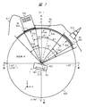
- FIG. 7 is an explanatory diagram simply showing the concept of the relationship between the shooting direction and the angle of view for a wide-angle image and a narrow-angle image that are a plurality of images used as specific examples in the imaging apparatus 1 of the first embodiment.
- FIG. 7 particularly shows the azimuth angle and the horizontal angle of view.
- the first image has a wide-angle image 6a
- the second image is a first narrow-angle image 6b
- a second narrow-angle image 6c are images taken by the user using the imaging device 1 at the point P0 that is the same location. It is assumed that the images were taken at close dates in the order of the wide-angle image 6a, the first narrow-angle image 6b, and the second narrow-angle image 6c.
- the shooting date and time of each image is, for example, 13:11:30 on Jan. 5, 2016 for the wide-angle image 6a, 13:14:40 for the first narrow-angle image 6b, and the same date for the second narrow-angle image 6c. 13:15:50.
- the wide-angle image 6a has an imaging range 601 corresponding to the imaging direction 63a indicated by the azimuth angle ⁇ 1 and the horizontal angle of view Ah1.
- the first narrow-angle image 6b has an imaging range 602 corresponding to the imaging direction 63b indicated by the azimuth angle ⁇ 2 and the horizontal field angle Ah2.
- the second narrow-angle image 6c has a shooting range 63c corresponding to the shooting direction 63c indicated by the azimuth angle ⁇ 3 and the horizontal field angle Ah3.
- the image capturing direction defined by the azimuth angle ⁇ is indicated by a one-dot chain line.
- the point P0 particularly indicates the center point of the lens 402 of the imaging unit 103.
- a spherical surface 600 represents a spherical surface of an omnidirectional sphere, and is a virtual spherical surface obtained by discarding points at infinity.
- the spherical surface 600 particularly indicates a circumferential portion corresponding to the azimuth angle ⁇ and the XY plane.
- N indicates north
- E indicates east
- S indicates south
- W indicates west.
- the X direction corresponds to the east
- the Y direction corresponds to the north
- the Z direction corresponds to the zenith direction.
- the azimuth angle ⁇ is indicated by assuming that N is 0 ° with respect to the reference, clockwise is the positive direction, E is + 90 °, S is + 180 °, and W is + 270 ° ( ⁇ 90 °).
- An imaging range 601 indicated by an arc on the spherical surface 600 indicates a portion corresponding to the horizontal field angle Ah1 in the wide-angle image 6a, and corresponds to an area projected on the spherical surface 600 viewed from the point P0.
- a case where there are a mountain 611, a sky, a tower 612, a building 613, and the like as a landscape captured on the spherical surface 600 on the wide-angle image 6a is simply shown.
- the first narrow-angle image 6b is an example in which the tower 612 is photographed
- the second narrow-angle image 6c is an example in which the building 613 is photographed.
- the wide angle image 6a has an azimuth angle ⁇ 1, an elevation angle ⁇ 1, a horizontal field angle Ah1, and a vertical field angle Av1
- the first narrow angle image 6b has an azimuth angle ⁇ 2, an elevation angle ⁇ 2, a horizontal field angle Ah2, and a vertical field angle Av2. It is assumed that the azimuth angle ⁇ 3, the elevation angle ⁇ 3, the horizontal field angle Ah3, and the vertical field angle Av3 of the angle image 6c.
- FIG. 8 is an explanatory view showing the elevation angle ⁇ and the vertical angle of view Av, as in FIG. FIG. 8 shows an example of another narrow-angle image 6d.
- the X direction corresponds to the horizontal direction
- the Z direction corresponds to the vertical direction.
- the positive direction in the Z direction corresponds to the head and zenith direction, and the negative direction corresponds to the foot direction.
- the elevation angle ⁇ is 0 ° with respect to the horizontal direction, + 90 ° in the zenith direction in the Z direction, and ⁇ 90 ° in the direction of the foot.
- An imaging range 801 corresponding to the vertical field angle Av4 in the narrow-angle image 6d is shown.
- a shooting direction 63d of the narrow-angle image 6d indicates a portion corresponding to the elevation angle ⁇ 4.
- FIG. 9 simply shows the view angle and the view angle related information.
- FIG. 9 shows a case where the setting section 14 stores the field angle and field angle related information as setting information.
- the field angle of the image ⁇ horizontal field angle Ah, vertical field angle Av ⁇ are shown.
- a horizontal size Sh corresponding to the horizontal angle of view Ah in the image and a vertical size Sv corresponding to the vertical angle of view Av are shown.
- the horizontal size Sh is a size from the right end to the left end in the horizontal direction in the image frame.
- the vertical size Sv is a size from the upper end to the lower end in the vertical direction in the image frame.
- the horizontal field angle Ah and the vertical field angle Av are used.
- the present invention is not limited to this, and at least one field angle including the diagonal field angle Ad may be used.
- the focal length f of the lens considering the optical zoom, the electronic zoom magnification n, and the dimensions of the imaging surface of the imaging device ⁇ horizontal size sw, vertical size sh, diagonal size sd ⁇ are used.
- a model may be used instead of the dimensions.
- the focal length f is a 35 mm equivalent focal length.
- the angle of view can also be obtained by calculation based on the relational expression using the angle-of-view related information.
- the control unit 101 may calculate the angle of view from the angle-of-view related information.
- the angle of view can be calculated using, for example, the dimensions of the image sensor, the focal length f, and the electronic zoom magnification n.
- the angle of view can be calculated from a relational expression uniquely determined as an arc tangent (arctan) using information such as a 35 mm equivalent focal length or an image sensor size.
- the imaging control unit 11 refers to the angle-of-view related information regarding the image.
- the imaging control unit 11 can grasp the angle-of-view related information from the setting information of the setting unit 14 described above or information described in the metadata 22 or the management information 21.
- the angle of view ⁇ horizontal angle of view Ah, vertical angle of view Av, diagonal angle of view Ad ⁇ can be calculated based on the following equation, for example.
- the control unit 101 describes the field angle information in the field angle item of the metadata 22 or the management information 21.
- the imaging apparatus 1 since the angle of view can be calculated from the angle-of-view related information, the imaging apparatus 1 may store the angle-of-view related information instead of saving the angle of view as one of the metadata 22 and the like.
- the image capturing apparatus 1 since the dimensions of the image sensor of the angle-of-view related information can be grasped from the model, the image capturing apparatus 1 may store the model instead of the dimensions of the image sensor as one of the metadata 22 and the like. Good.
- the imaging apparatus 1 holds information representing a correspondence relationship between the model and the angle-of-view related information in advance.
- the imaging device 1 can refer to information representing the correspondence relationship from an external device through communication.
- the imaging device 1 can obtain angle-of-view related information from the model based on the information.
- the image pickup apparatus 1 When the image pickup apparatus 1 picks up an image, the image pickup apparatus 1 creates information including a shooting date and time, a shooting direction ⁇ azimuth angle ⁇ , elevation angle ⁇ , a field angle ⁇ horizontal field angle Ah, vertical field angle Av ⁇ , and the like.
- the imaging control unit 11 obtains the shooting date and time using the internal clock 112.
- the imaging control unit 11 obtains position information ⁇ latitude, longitude, altitude ⁇ by the position detection unit 113.
- the imaging control unit 11 obtains the imaging direction ⁇ azimuth angle ⁇ and elevation angle ⁇ by the imaging direction measurement unit 111.
- the imaging control unit 11 obtains an angle of view ⁇ horizontal angle of view Ah and vertical angle of view Av ⁇ by setting information or calculation of the setting unit 14. Then, the imaging apparatus 1 describes the information in corresponding items of the metadata 22 in FIG. 5 and creates the image file 24 together with the image data 23.
- FIG. 10 shows a display mode of the display screen 401 of the display unit 41 and its transition.
- the imaging apparatus 1 has at least a first display mode, a second display mode, and a third display mode as display modes that are playback display modes. For example, the imaging apparatus 1 initially displays in the first display mode, and switches the display mode based on a user operation.
- the first display mode is a mode for displaying a list of information on all images, and a mode for displaying a folder screen.
- information on a plurality of images in the folder is displayed in a list in the order of, for example, file names and date / time.
- information such as images G1, G2, and G3 is displayed as a plurality of images in order from the top.
- an image icon or thumbnail, file name, shooting date, type, and other information are displayed.
- attribute values such as the shooting direction ⁇ azimuth angle ⁇ , elevation angle ⁇ and field angle ⁇ horizontal field angle Ah, vertical field angle Av ⁇ may be displayed.
- the user can scroll and display information that cannot be displayed on the first screen.
- the first screen is not limited to such a folder screen, and various known methods are possible. For example, a screen that displays thumbnails of a plurality of images in a two-dimensional parallel arrangement is possible.
- the user selects and operates a desired first image, for example, the image G1 (corresponding to the wide-angle image 6a).
- the imaging device 1 makes a transition to the second screen in the second display mode.
- the second display mode is a unique mode in which association display is performed on a plurality of images including a wide-angle image and a narrow-angle image.
- the wide-angle image 6a that is the selected first image 901 is displayed as a whole, and one or more second images having a predetermined relationship are displayed on the first image 901.
- a narrow-angle image is displayed in a state of being overlapped and related in a state of a predetermined graphic 902.
- the graphic 902 is a graphic representing the first narrow-angle image 6b
- the graphic 903 is a graphic representing the second narrow-angle image 6c.
- the broken line frame indicates a region where the corresponding narrow-angle image is present for easy understanding.
- the display state can be changed by an operation such as scrolling or enlarging / reducing according to the user operation.
- the desired second image figure is selected and operated by the user on the second screen.
- the selection operation is, for example, a figure tap.
- the imaging apparatus 1 makes a transition to the third screen in the third display mode for displaying the selected second image.
- a predetermined operation for returning to the first display mode is performed on the second screen, the imaging device 1 returns to the first screen in the first display mode.
- the predetermined operation is, for example, a first display mode designation input or a return button press.
- the third display mode is a mode for performing detailed display regarding a designated single image, for example, a narrow-angle image.
- a narrow-angle image that is a single second image 904 is displayed on the third screen, but a single wide-angle image can be displayed in the same manner.
- On the third screen in the third display mode it is also possible to change the display state by scrolling, enlarging / reducing, or the like according to a user operation.
- a predetermined operation on the third screen for example, a second display mode designation input or a tap on the area of the second image 904, the imaging device 1 returns to the second screen in the second display mode.
- the imaging device 1 displays only the first image in detail on the display screen in accordance with a predetermined operation. For example, in response to a predetermined operation on the second screen, the imaging apparatus 1 hides the graphic of the second image, thereby displaying only the first image. The imaging device 1 returns the graphic of the second image to the display state again in response to a predetermined operation from that state. Alternatively, the imaging apparatus 1 transitions to a third screen that displays the first image in detail in response to a predetermined operation on the second screen, for example, a tap on a region where there is no figure of the second image on the first image.
- FIG. 11 shows an example of the second screen in the second display mode. This example corresponds to the specific example of FIG. 7 and the like, and shows a case where the wide-angle image 6a is selected and displayed. A case where the first narrow-angle image 6b and the second narrow-angle image 6c are associated with the wide-angle image 6a is shown.
- the display control unit 12 displays the second screen based on the image file 24 and the management information 21. On the second screen, the wide-angle image 6a that is the first image is displayed as a whole, and a graphic representing each narrow-angle image that is the second image is superimposed on the first image.
- FIG. 11 shows the horizontal direction in the screen corresponding to the azimuth angle in the display screen 401 as the x direction and the vertical direction in the screen corresponding to the elevation angle as the y direction.
- the horizontal width of the display screen 401 in the x direction is W
- the vertical width in the y direction is H.
- the point p1 indicates the center point of the display screen 401.
- the entire wide-angle image 6a is displayed in the display screen 401 in a state in which operations such as scrolling and enlargement / reduction are not performed.
- the position coordinate (Xa, Ya) of the center point corresponding to the shooting direction 63a of the wide-angle image 6a is displayed at the point p1.
- the horizontal angle of view Ah1 of the wide-angle image 6a is 120 °
- the vertical angle of view Av1 is 80 °
- the wide-angle image 6a is displayed in a horizontal size Sh1 corresponding to the horizontal field angle Ah1 and a vertical size Sv1 corresponding to the vertical field angle Av1 in correspondence with the horizontal width W and the vertical width H of the display screen 401.
- the right end position Xar corresponds to an azimuth angle of 70 °
- the left end position Xal corresponds to an azimuth angle of ⁇ 50 °
- the upper end position Yat corresponds to an elevation angle of 40 °
- the lower end position Yab corresponds to an elevation angle ⁇ Corresponds to 40 °.
- a mark which is a graphic representing a narrow-angle image, is superimposed on the wide-angle image 6a.
- a mark 8b representing the first narrow-angle image 6b and a mark 8c representing the second narrow-angle image 6c are shown as marks.
- the mark particularly indicates a balloon shape.
- the mark is variable based on user settings.
- the center point p2 indicates a position where the mark 8b representing the first narrow-angle image 6b is displayed.
- the center point p3 indicates the position where the mark 8c representing the second narrow-angle image 6c is displayed.
- the position (Xb, Yb) of the center point p2 corresponds to (+ 45 °, 0 °) in (azimuth angle, elevation angle), and the position (Xc, Yc) of the center point p3 is ( ⁇ 20 °, ⁇ 10 °). ).
- the display control unit 12 determines and displays the display position of the mark of the second image on the first image based on information such as the shooting direction and the angle of view of the second image associated with the first image.
- the position (Xb, Yb) of the center point p2 of the first narrow-angle image 6b is the difference between the azimuth angle (35 °) and the elevation angle difference (35 °) from the point p1 of the wide-angle image 6a when the wide-angle distortion and distortion are ignored. 0 °) is obtained by the following equation.
- the position (Xc, Yc) of the center point p3 of the second narrow-angle image 6c is the difference between the azimuth angle ( ⁇ 30 °) and the elevation angle from the point p1 of the wide-angle image 6a when the wide-angle distortion and distortion are ignored. ( ⁇ 10 °) and the following formula.
- Xc (W / 2) ⁇ tan ( ⁇ 30 °) / tan 60 ° (6)
- Yc (H / 2) ⁇ tan ( ⁇ 10 °) / tan40 ° (7)
- the user selects, for example, taps a desired mark on the display screen 401. Thereby, the second image corresponding to the mark can be selected and displayed on the third screen in the third display mode. Note that the example of FIG. 11 shows a case where the entire wide-angle image 6a can be initially displayed with respect to the size of the display screen 401.
- the display control unit 12 may display a part of the wide-angle image, that is, a part of the angle of view, or display it as a state in which the entire image is reduced to fit. May be.
- values such as the shooting direction and the angle of view may be displayed as auxiliary browsing information, or icons for operations such as scrolling and enlarging / reducing may be displayed.
- FIG. 12 shows a display of the first narrow-angle image 6b when the mark 8b of the first narrow-angle image 6b is selected as a display example of the third screen in the third display mode.
- the first narrow-angle image 6 b is displayed on the entire display screen 401.
- the center point p1 of the display screen 401 is displayed in a state where the center point p2 of the first narrow-angle image 6b and the mark 8b is arranged.
- the horizontal angle of view Ah2 of the first narrow-angle image 6b is 21 °
- the vertical angle of view Av2 is 14 °.
- the right end position Xbr corresponds to an azimuth angle of + 55.5 °
- the left end position Xbl corresponds to an azimuth angle of + 34.5 °
- the upper end position Ybt corresponds to an elevation angle of + 7 °
- the lower end position Ybb corresponds to an elevation angle.
- FIG. 13 shows a display of the second narrow-angle image 6c when the mark 8c of the second narrow-angle image 6c is selected as an example of the third screen in the third display mode.
- the second narrow-angle image 6 c is displayed on the entire display screen 401.
- the center point p1 of the display screen 401 is displayed with the second narrow-angle image 6c and the center point p3 of the mark 8c being arranged.
- the horizontal angle of view Ah3 of the second narrow-angle image 6c is 21 °, and the vertical angle of view Av3 is 14 °.
- the right end position Xcr corresponds to ⁇ 9.5 ° in azimuth
- the left end position Xcl corresponds to ⁇ 30.5 ° in azimuth
- the upper end position Yct corresponds to ⁇ 3 ° in elevation
- Ycb corresponds to ⁇ 17 ° in elevation.
- this is not limited to the transition from the second display mode to the third display mode.
- An operation mode in which the first display mode is changed directly to the third display mode by a predetermined operation without passing through the second display mode is also possible, and the operation mode can be selected according to user settings and the like.
- Association method there are a first method and a second method with respect to timing of associating.
- the first method is a method for performing association at the time of imaging
- the second method is a method for performing association at the time of reproduction display.
- the imaging device 1 uses the first method
- the display device 2 uses the second method.
- the imaging device 1 performs an association process using the association unit 15 immediately after taking an image, and as a result, the association information is described in the metadata 22 or the management information 21.
- the imaging apparatus 1 can grasp the relationship between the plurality of images from the reference to the association information of the metadata 22 or the management information 21 and displays the relationship on the display screen in the second display mode.
- the display device 2 when the display device 2 reproduces and displays on the display screen based on the image file 24, the display device 2 performs association processing using the association unit 215, and as a result, displays on the display screen in the second display mode.
- the display device 2 may omit the description of the association information in the metadata 22 or the management information 21 by performing the association process for each reproduction display.
- the display device 2 performs association processing at the first reproduction / display of an image, describes the association information in the metadata 22 and the management information 21, and then reproduces the image for the second and subsequent times.
- the association process may be omitted with reference to the association information.
- the second method may be adopted in the imaging device 1 of another embodiment. Which of the association methods is adopted may be fixed in terms of mounting, or may be selected and set in accordance with user settings.
- FIG. 14 shows a flow of control processing when an image is picked up by the image pickup apparatus 1.
- FIG. 14 has steps S101 to S106. The same processing is repeated every time an image is captured. Hereinafter, it demonstrates in order of a step.
- the control unit 101 sets an angle of view and the like for the setting unit 14 based on a user operation.
- the imaging control unit 11 grasps the angle of view and the like based on the setting information of the setting unit 14.
- the imaging control unit 11 controls the imaging unit 103 to capture an image, obtains image data 23, and stores the image data 23 in the storage unit 102.
- the imaging control unit 11 describes the angle of view or the angle-of-view related information in the metadata 22 or the management information 21 of the image file 24.
- (S103) Branching is performed according to the first method in which association is performed at the time of imaging or the second method in which association is performed during playback display.
- the process proceeds to S104, and in the case of the second method, the process proceeds to S106. That is, the imaging apparatus 1 of the first embodiment proceeds to S104 in order to employ the first method, and proceeds to S106 when the second system is employed in the imaging apparatus 1 of the other embodiments.
- the associating unit 15 performs a predetermined associating process. Thus, a plurality of images including the first image and the second image are associated.
- the associating unit 15 creates association information as a result of the associating process, and describes it in the metadata 22 or the management information 21 of the image file 24.
- the imaging control unit 11 stores the image file 24 in the storage unit 102 and records it in the recording medium 107 of the recording unit 106.
- the control unit 101 stores the image file 24 in the storage unit 102 and records it on the recording medium 107 of the recording unit 106.
- FIG. 15 shows a flow of control processing at the time of reproducing and displaying an image in the imaging device 1 or the display device 2.
- the control in FIG. 15 corresponds to the control for changing the display mode as shown in FIG. FIG. 15 includes steps S201 to S210.
- steps S201 to S210 it demonstrates in order of a step.
- the imaging device 1 is the main body
- the display device 2 is the main body.
- the control unit 101 Based on the user operation, the control unit 101 causes the display control unit 12 to display the first screen in the first display mode on the display screen 401 of the display unit 41 of the display device 104 as shown in FIG.
- the display control unit 12 accepts selection of an image in the first screen in response to a user input operation.
- the display control unit 12 branches depending on whether the image selected on the first screen in the first display mode is a wide-angle image that is the first image or a narrow-angle image that is the second image. If it is the first image, the process proceeds to S203, and if it is the second image, the process proceeds to S209.
- the display control unit 12 performs branching according to the first method or the second method. In the case of the second method, the process proceeds to S204, and in the case of the first method, the process proceeds to S206. That is, in the case of the imaging apparatus 1 of Embodiment 1, since it is a 1st system, it progresses to S206, and in the case of the display apparatus 2, since it is a 2nd system, it progresses to S204.
- the display control unit 12 uses the associating unit 15 to associate a plurality of images immediately before reproduction display.
- the display control unit 12 confirms the association with reference to the association information in the metadata 22 or the management information 21 of the image file 24 of the first image.
- the display control unit 12 reads the image data 23 of the second image associated with the first image.
- the display control unit 12 displays the image data 23 as a result of S205 or S206 on the display screen in the second display mode. That is, the display control unit 12 displays the second image on the first image in a state of being associated with the first image, as in the second screen of FIG.
- the display control unit 12 accepts selection of a graphic of the second image in the second screen in accordance with a user input operation. For example, when the user wants to view the second image, the user taps the mark, and when he wants to return to the first screen, the user taps the area of the first image.
- the display control unit 12 branches depending on whether the image selected on the second screen in the second display mode is a mark representing the second image. If it is a mark representing the second image, the process proceeds to S209. In the case of another operation, for example, an operation on the area of the first image, this corresponds to a return operation, and in this case, the process returns to S201.
- the display control unit 12 uses the image data 23 of the second image corresponding to the mark selected in S208, in the third display mode on the display screen, as in the third screen in FIG. Two images are displayed in detail.
- the display control unit 12 receives a return operation or the like in the third screen in response to a user input operation. For example, when the user wants to return to the second screen, the user taps the area of the second image.
- the associating unit 15 associates a plurality of images.
- the association process includes a first process and a second process.
- the first process is a process for selecting an image as a candidate for association based on a selection condition of a predetermined selection method.
- a predetermined selection method there are a first selection method, a second selection method, and a third selection method described below.
- the first selection method is used.
- the second selection method or the third selection method is used. Note that which selection method is adopted may be a fixed form in terms of mounting or a form that can be variably selected by user settings.
- FIG. 16 is an explanatory diagram showing the first selection method.
- the first selection method uses a condition related to the shooting location as a selection condition.
- images that are determined to have roughly the same shooting location are selected as candidates.
- position information ⁇ latitude, longitude, altitude ⁇ by the position detection unit 113 is used to determine the shooting location.
- the associating unit 15 refers to the position information ⁇ latitude, longitude ⁇ described in the shooting location item of the metadata 22 at the time of imaging, for example.
- ⁇ Latitude, Longitude ⁇ is represented by ⁇ LA, LO ⁇ .
- the associating unit 15 takes the position 1601 representing the shooting location of the first image in the space, for example, the XY plane, with the wide-angle image as the first image as a reference.
- the position 1601 is represented by ⁇ LA1, LO1 ⁇ .
- a position range 1600 corresponds to a threshold value of a condition, and indicates a circular area having a predetermined radial distance with the position 1601 as a central point.
- the radial distance that defines the position range 1600 may be a fixed set value in design or a set value that can be varied by user setting.
- the associating unit 15 compares the position of each narrow-angle image that is the second image with the position 1601 of the first image.
- a first narrow-angle image position 1602 ⁇ LA2, LO2 ⁇ , a second narrow-angle image position 1603 ⁇ LA3, LO3 ⁇ , and a third narrow-angle image position 1604 ⁇ LA4, LO4 around the wide-angle image. ⁇ Is shown.
- the associating unit 15 searches for an image included in the position range 1600 with respect to the position 1601 of the first image.
- the position range 1600 includes the position 1602 of the first narrow-angle image and the position 1603 of the second narrow-angle image, and does not include the position 1604 of the third narrow-angle image.
- the associating unit 15 determines that the second image whose position is included in the position range 1600 is an image captured at approximately the same shooting location as the first image, and selects it as an association candidate.
- the same photographing location there is a case where a user photographs each direction of 360 ° while circling a circle along a handrail at a certain observation deck.
- FIG. 17 is an explanatory diagram showing the second selection method.
- the second selection method uses a condition related to the shooting date and time as a selection condition.
- images that are determined to have substantially the same shooting date and time are selected as candidates.
- the associating unit 15 refers to, for example, the shooting date (year / month / day / hour / minute / second) described in the shooting date / time item of the metadata 22.
- the associating unit 15 takes a time point t1 representing the shooting date and time of the first image with reference to the wide-angle image that is the first image in the time series of the shooting date and time.
- the time point t1 is the date and time DT3.
- the date / time range 170 corresponds to a threshold value of the condition, and indicates a range by a predetermined time including the time t1 as a central point and before and after.
- the time for defining the date and time range 170 may be a fixed set value by design or a set value that can be varied by user setting.
- the date and time range 170 can be set, for example, 1 day (24 hours), 1 hour, 5 minutes, or the like.
- the associating unit 15 searches for the second image included in the predetermined date and time range 170 with respect to the time t1 of the shooting date and time of the first image.
- the associating unit 15 compares the shooting date and time of each narrow-angle image that is the second image with respect to the time t1 of the shooting date and time of the first image.
- time t2 of the first narrow-angle image shooting date there is shown a case where there is a time t2 of the first narrow-angle image shooting date, a time t3 of the second narrow-angle image, and a time t4 of the third narrow-angle image in the vicinity of the time t1.
- the date and time range 170 includes the time point t2 of the first narrow-angle image and the time point t3 of the second narrow-angle image, and does not include the time point t4 of the third narrow-angle image.
- the control unit 101 determines that the second image whose time point is included in the date and time range 170 is an image captured at approximately the same shooting date and time as the first image, and selects it as an association candidate.
- FIG. 18 is an explanatory diagram showing the third selection method.
- the third selection method uses a condition relating to a set character string that can be arbitrarily set by the user as a selection condition.
- images that are determined to have substantially the same set character string are selected as candidates.
- the associating unit 15 refers to, for example, a character string set as a setting character string of association management information after imaging.
- FIG. 18 shows an example of a list display of information of a plurality of images on the first screen in the first display mode.
- a file name, shooting date / time, tag, type, and the like are displayed as information.
- the “tag” item corresponds to a setting character string.
- the user can arbitrarily set a character string in the “tag” item in the editing operation.
- the user sets a character string representing the shooting location in the “tag” item.
- the images G1, G2, and G3 are images taken in the same park, and the character string “A park” is set.
- the images G4 and G5 are images taken at the same observatory, and the character string “B observatory” is set.
- the “type” item displays “wide angle” or “narrow angle” as the type of angle of view of the image.
- the associating unit 15 refers to the set character string of the “tag” item of the first image on the basis of the first image selected by the user, for example, the image G1.
- the associating unit 15 compares the set character string of the first image with reference to the set character string of each narrow-angle image that is the other second image, and, for example, sets the character string that includes the same character string. Find the image you have. For example, the set character strings of the images G1, G2, and G3 are the same.
- the associating unit 15 determines that these images are images taken at the same shooting location and selects them as candidates for association.
- the control unit 101 may automatically set a character string indicating a shooting location at the time of imaging or the like without depending on a user operation. For example, the control unit 101 may determine a character string representing a shooting location based on the position information ⁇ latitude, longitude ⁇ . The control unit 101 may set a character string in the “file name” item of the image. For example, the control unit 101 may automatically assign a file name including a set character string according to a predetermined rule. Examples of file name rules include [shooting date and time] + [setting character string (shooting location)] + [individual sequence number].
- the above selection methods can be applied in combination.
- the condition of the shooting location of the first selection method and the shooting date condition of the second selection method may be combined.
- the condition for example, “up to the past one year at the same shooting location” can be designated.
- the second process in the associating process of the associating unit 15 is as follows.
- the image selected as the candidate in the first process is determined to be associated using information on the shooting direction and the angle of view, and is associated according to the determination result.
- the associating unit 15 refers to the shooting direction and angle of view information in the metadata 22 or the management information 21 of each image file 24.
- the associating unit 15 sets the shooting direction of the candidate image ⁇ azimuth angle ⁇ , elevation angle ⁇ within the range of the angle of view ⁇ horizontal angle of view Ah, vertical angle of view Av ⁇ of the wide-angle image that is the first reference image. ⁇ Is included.
- the associating unit 15 determines an image satisfying this condition as an image to be associated.
- the azimuth angle ⁇ 2 45 ° of the shooting direction 63b of the first narrow-angle image 6b is included in the range ( ⁇ 50 ° to + 70 °) of the horizontal angle of view Ah1 of the wide-angle image 6a.
- the azimuth angle ⁇ 3 ⁇ 20 ° in the shooting direction 63c of the second narrow-angle image 6c is included.
- the elevation angle ⁇ 3 ⁇ 10 ° in the photographing direction 63c of the two narrow-angle image 6c is included. Therefore, the first narrow-angle image 6b and the second narrow-angle image 6c are associated with the wide-angle image 6a.
- the associating unit 15 may describe the association management information in the management information 21 as described above, or describe similar information in the metadata 22 of each image. May be.
- the imaging control unit 11 acquires the moving image data 23 by changing the electronic zoom magnification and the angle of view in a continuous shooting mode.
- the imaging control unit 11 describes information such as the electronic zoom magnification and the angle of view corresponding to the time point in the metadata 22 or the management information 21 for the moving image file 24.
- the display control unit 12 displays a mark or the like on the second screen in the second display mode, for example, corresponding to the position of the image frame at the start of the moving image or the image frame in the paused state. May be displayed.
- the display control unit 12 reproduces and displays a moving image on the second screen in the second display mode, the shooting date and time described in the metadata 22 and the like, position information, and a shooting direction that changes according to the time, etc.
- the display position of the figure is determined based on the above.
- the display position may be, for example, one fixed display position according to the shooting direction of the first image frame constituting the moving image, or may be a display position determined from statistical values of a plurality of image frames.
- the display position may be a display position corresponding to the shooting direction that changes according to the image frame.
- the imaging device 1 and the display device 2 of Embodiment 1 it is easy to grasp the relationship between a plurality of images including wide-angle images and narrow-angle images, and better usability can be realized.
- the related narrow-angle image is automatically superimposed on the wide-angle image, so that the user can easily recognize a plurality of related images and intuitively understand it.
- the user can recognize a narrow-angle image existing within the angle of view of the wide-angle image, and can browse quickly by referring to the associated narrow-angle image.
- the user can preferably browse a large number of images while switching the display mode.
- the relationship between the angles of view may be relatively determined with respect to the type of image. That is, the imaging device 1 or the display device 2 refers to the angle of view in a plurality of images, and sets the image having the maximum angle of view as the first image that is a wide-angle image, and images other than the first image. Is a second image which is a narrow-angle image.
- FIG. 19 shows an example of the second screen in the second display mode in the imaging apparatus 1 according to the modification of the first embodiment.
- FIG. 19 corresponds to the specific example of FIG.
- a graphic representing the second image is not a mark but a transparent frame.
- the transmission frame 9b represents the first narrow-angle image 6b
- the transmission frame 9c represents the second narrow-angle image 6c.
- the transparent frame has four sides of a rectangle displayed with lines and colors, and the inside thereof is a transparent region, and the first image portion in the background is displayed as it is.
- the size of the transparent frame area on the display is determined in accordance with the size of the angle of view of the second image. This makes it easier to grasp the relationship between the narrow-angle images in the wide-angle image.
- the wide-angle image 6a is displayed on the display screen 401 at the reference position similar to that in FIG. 11, and then scrolled and enlarged / reduced based on the user operation.
- a state in which the angle of view range is moved and changed is shown.
- a point corresponding to (+ 15 °, + 10 °) in (azimuth angle, elevation angle) is arranged as the viewpoint position (Xa, Ya) of the wide-angle image 6a at the center point p1 of the display screen. .
- the range of 90 ° in the range of 120 ° of the horizontal angle of view of the wide-angle image 6a and the range of 60 ° in the range of 80 ° of the elevation angle are displayed in an enlarged manner.
- the position Xa is 15 ° in azimuth
- the position Ya is 10 ° in elevation.
- the right end position Xar corresponds to 60 °
- the left end position Xal corresponds to ⁇ 30 °
- the upper end position Yat corresponds to 40 °
- the lower end position Yab corresponds to ⁇ 20 °.
- the position coordinates (Xb, Yb) of the center point p2 of the transmission frame 9b correspond to (+ 45 °, 0 °) in (azimuth angle, elevation angle).
- the position and size of the transmission frame 9c are determined in the same manner.
- the position coordinates (Xc, Yc) of the center point p3 of the transmission frame 9c correspond to ( ⁇ 20 °, ⁇ 10 °).
- the display position ⁇ Xbr, Xbl, Ybt, Ybb ⁇ of the transmission frame 9b and the display position ⁇ Xcr, Xcl, Yct, Ycb ⁇ of the transmission frame 9c are obtained by the following formulas when wide-angle distortion and distortion aberration are ignored. Note that the coefficient Kw and the coefficient Kh are used.
- the display control unit 12 determines the size of the transmission frame using the information on the shooting direction and the angle of view of the image of the image data 23.
- the display control unit 12 determines the position and size of the transparent frame so as to correspond to the display state after the change when scrolling or enlargement / reduction corresponding to the viewpoint change in the display of the wide-angle image is performed.
- This modification has the advantage that the range and positional relationship of the narrow-angle image can be easily understood by displaying the transparent frame.
- thumbnails may be displayed with the same size instead of the transparent frame.
- FIG. 20 shows an example of a display screen in the imaging apparatus 1 according to the modification of the first embodiment.
- the upper side of FIG. 20 shows an example of the first screen in the first display mode.
- thumbnails of wide-angle images and thumbnails of narrow-angle images are displayed in a list in a vertical and horizontal arrangement.
- the size of the thumbnail on the display is determined to be a vertical and horizontal size corresponding to the angle of view of the image.
- a wide-angle image thumbnail 2001 in this example is a panoramic image thumbnail having a large horizontal angle of view of 180 ° or more.
- a thumbnail 2002 of a narrow-angle image indicates a case where the thumbnail is an image having a horizontal angle of view of less than 180 °.
- the number of images when arranged in parallel is variable such as two, three, four, etc. in one direction. The user can distinguish between the wide angle and the narrow angle based on the size of the thumbnail.
- the lower side of FIG. 20 shows an example of the second screen in the second display mode.
- the display screen 401 includes a main area 1001 and areas other than the main area 1001, in this example, a right-side area 1002 and a lower-side area 1003.
- a mark or the like of the second image is superimposed on the first image in the second display mode.
- a part of the angle of view is initially displayed with the shooting direction as the center point.
- a range corresponding to a part of the horizontal angle of view of the wide-angle image selected on the first screen is displayed in the area 1001.
- the user can change the display state of the first image in the region 1001 by scrolling, enlarging, reducing, or the like according to the viewpoint change or the like.
- a different graphic may be displayed according to a difference in image type, shooting date and time.
- image type for example, a type corresponding to the difference in the angle of view may be set based on user settings or the like.
- information may be given to the graphic for display. In this example, an identification number is assigned to the mark.
- an attribute value such as a shooting date and time based on the metadata 22 or the management information 21 may be displayed as information on the graphic, or only the attribute value may be displayed.
- information of all the plurality of second images associated with the first image such as marks and attribute values, are displayed in parallel.
- some of the marks of the second image are displayed according to the display state, and the marks of the other second images are not displayed.
- information on the second image that is not displayed in the area 1001 is also displayed.
- the transition to the third display mode may be performed.
- a thumbnail of the second image selected last is displayed as a preview.
- a display mode information on the first image, operation buttons, setting information, and the like are displayed. For example, information indicating that the current display mode is the second display mode and attribute values such as the shooting date and time of the first image are displayed.
- a button for switching between displaying and hiding the mark in the second display mode is provided. In the “ON” state, a mark is displayed, and in the “OFF” state, the mark is not displayed, that is, only the first image is displayed.
- a return button or the like for returning from the second display mode to the first display mode is provided.
- the representative mark is a star.
- a pop-up area 1005 is displayed on the first image, and information on the plurality of second images is displayed in the pop-up area 1005.
- information on a plurality of second images associated with the representative mark may be displayed in the area 1002 or the like on the right side.
- a plurality of associated second images may be sequentially displayed in a predetermined area according to selection of a representative mark, that is, a slide show may be displayed. For example, when there are a plurality of images taken at the same place and in the same shooting direction at different shooting dates and times, these images can be linked and reproduced and displayed continuously.
- an area where a plurality of second images are densely displayed may be enlarged according to a representative mark selection operation so that the marks of the plurality of second images can be distinguished.
- the imaging device 1 and the display device 2 may store the image file 24 in an external device, or may read and reproduce the image file 24 from an external device.
- the imaging device 1 and the display device 2 may perform association processing for the image file 24 to be transmitted to an external device, and may transmit the image file 24 including the association information to the external device.
- the imaging device 1 and the display device 2 may perform association processing for the image file 24 received from an external device, and reproduce and display the image file 24 in a state of being associated based on the association information. That is, as an association method other than the first method and the second method described above, a method of performing association before transmitting the image file 24 to an external device, or a method of performing association after receiving the image file 24 from an external device.
- the imaging device 1 and the display device 2 may describe angle-of-view information and association information as metadata 22 for each image file 24. It may be provided by being described in a management file different from the image file 24.
- the imaging apparatus 1 performs an association process on a plurality of captured images before transmitting them to the server 3, creates an image file 24 including an angle of view and association information, and creates a communication network 4.
- the imaging device 1 or the display device 2 accesses the server 3 through the communication network 4 and acquires the image file 24 from the image data DB of the server 3.
- a plurality of image files 24 can be acquired collectively by specifying, for example, a shooting date and time, a shooting location, etc. as a search condition.
- the imaging device 1 or the display device 2 reproduces and displays the acquired image data 23 of the plurality of image files 24 in an associated state based on the reference of the association information.
- the imaging apparatus 1 transmits the image file 24 that includes the angle of view and does not include the association information to the server 3 and stores the image data DB in the image data DB without performing the association process for the plurality of captured images.
- the imaging device 1 or the display device 2 accesses the server 3 through the communication network 4 and acquires the image file 24 from the image data DB of the server 3.
- the imaging device 1 or the display device 2 performs association processing on the acquired plurality of image files 24, and reproduces and displays them in an associated state based on the angle of view and the association information.
- the server 3 may perform association processing for a plurality of image data 23 in the image data DB.
- the server 3 performs the association process and stores it as an image file 24 including association information.
- the imaging device 1 or the display device 2 reproduces and displays the plurality of image files 24 acquired from the server 3 based on the association information reference.
- the imaging device 1 performs association processing for a plurality of captured images, and transmits an image file 24 including an angle of view and association information to the display device 2.
- the display device 2 acquires the image file 24, and reproduces and displays the image data 23 of the acquired image file 24 in an associated state based on the reference of the association information.
- the imaging device 1 transmits the image file 24 including the angle of view and not including the association information to the display device 2 without associating the plurality of captured images.
- the display device 2 acquires the image file 24, performs association processing on the image data 23 of the acquired image file 24, and reproduces and displays the image data 24 in an associated state based on the association information.
- the imaging device 1 and the display device 2 may read the respective image files 24 from a plurality of devices of the same user, and manage them by integrating them.
- the first imaging device 1A and the second imaging device 1B in FIG. 1 each transmit the image file 24 of the captured image to the first display device 2A without associating.
- the first display device 2A performs association processing on these image files 24, and reproduces and displays them in the associated state.
- the association display function can be realized in a system in which a plurality of devices cooperate, and the user can associate and save a large number of images.
- an editing function is provided that allows the user to determine the association of a plurality of images and manually set and edit them. Using the editing function, the user can add, delete, or change an associated image on the display screen, and can change the display position of each image.
- FIG. 21 shows an example of the second screen in the second display mode in the imaging device 1 and the display device 2 of the modification.
- the following shows the case of the imaging device 1 having an editing function, but the same applies to the case of the display device 2 having an editing function.
- Based on user settings or input operations it is possible to switch between an “ON” state in which editing is valid and an “OFF” state in which editing is invalid.
- the second screen in the second display mode associates the second image with the first image, the display position of the graphic of the second image, and the like based on the user input operation.
- the control unit 101 stores and manages the display position of the graphic of the second image as one of the metadata 22 or the management information 21. At the time of reproduction display, the control unit 101 refers to the information and determines the graphic display position.
- a transparent frame is displayed as a graphic of the second image.
- the imaging apparatus 1 automatically determines and displays the display position of the second image, as in the first embodiment.
- a transmission frame 9b1 representing the first narrow-angle image 6b is displayed.
- the user touches the transparent frame 9b1 of the second image, for example, and moves it to a desired direction and position.
- the control unit 101 updates the display state so as to move the display position of the graphic according to the user operation.
- the state after movement of the transmission frame 9b1 is shown as a transmission frame 9b2.
- the center point of the first narrow-angle image 6b is the point p22 after movement from the point p21 before movement.
- the control unit 101 updates the management value so as to store the moved position of the graphic of the second image as a new display position.
- the control unit 101 may display information for confirming the change of the display position after moving the graphic of the second image, and confirm with the user whether or not to change and save. For example, the control unit 101 displays a pop-up area near the moved position, and displays “The display position has been moved. Save / do not save” or the like. The user confirms this and presses a “save” button, for example. Thereby, the control part 101 preserve
- the editing function has a function of adding a second image to be associated and a function of releasing the association of the second image.
- the user touches a desired position in the display screen, for example, the point p23 and designates addition.
- the user can select the second image to be added by an add button in the pop-up area.
- the control unit 101 displays a graphic related to the selected second image at the position, and stores the display position of the second image in the management value.
- the user selects the figure of the second image displayed in the display screen and designates cancellation. For example, the user touches the transparent frame 9c of the second narrow-angle image 6c and presses the release button in the pop-up area.
- the control unit 101 cancels the association of the second image for which cancellation is specified, deletes the display, and updates the management value.
- the editing function allows the user to freely edit the association display of the plurality of images in the second display mode so that the user can easily see and grasp the images.
- the imaging device and display device according to the second embodiment of the present invention will be described with reference to FIGS. In the following, portions of the configuration of the second embodiment that are different from the configuration of the first embodiment will be described.
- the imaging device 1 according to the second embodiment has a function of capturing an omnidirectional image as a wide-angle image, and has a function of displaying the wide-angle image in association with the first image.
- a virtual spherical surface 600 set with the position of the user who is the imaging device and the photographer as the center point is referred to as an omnidirectional sphere.
- the omnidirectional image is an image having 360 ° as an angle of view of at least one of a horizontal angle of view and a vertical angle of view.
- FIG. 22 shows the omnidirectional image in the second embodiment with a horizontal angle of view.
- the spherical surface 600 corresponding to the omnidirectional sphere has a first wide-angle image 6A, a second wide-angle image 6B, and a narrow-angle image 6C.
- the first wide-angle image 6A is a wide-angle image having a shooting range 2201 of 180 ° with a horizontal angle of view as viewed from the front camera side of the imaging device 1 in the front shooting direction (for example, northward).
- the second wide-angle image 6B is a wide-angle image having a shooting range 2202 of 180 ° in the horizontal angle of view as viewed from the rear camera side in the rear shooting direction (for example, southward).
- the narrow-angle image 6C is a narrow-angle image having a shooting range 2203 with a horizontal angle of view Ah in a desired shooting direction (for example, northward) from the front camera side.
- a desired shooting direction for example, northward
- an omnidirectional image that is a wide-angle image having a shooting range of 360 ° at a horizontal angle of view is formed.
- the first wide-angle image 6A has a shooting range of 180 ° at the vertical angle of view.
- FIG. 23 shows a configuration of a part related to the imaging unit 103 in the imaging apparatus 1.
- the imaging apparatus 1 includes a first imaging unit 103A, a second imaging unit 103B, and a third imaging unit 103C as the imaging unit 103, and these are connected to the interface circuit 131.
- the first imaging unit 103A is an imaging unit corresponding to the front camera, and includes a drive unit 31a and a lens unit 32a.
- the lens unit 32a includes a first lens as a super-wide-angle lens that can capture the first wide-angle image 6A in the imaging range (ie, hemisphere) of 180 ° with the front horizontal and vertical angles of view.
- the second imaging unit 103B is an imaging unit corresponding to the rear camera, and includes a drive unit 31b and a lens unit 32b.
- the lens unit 32b includes a second lens as a super-wide-angle lens that can capture the second wide-angle image 6B in the imaging range of 180 ° (that is, a hemisphere) with the horizontal and vertical angle of view on the back.
- the third imaging unit 103C has the same configuration as that of the imaging unit 103 according to Embodiment 1, and includes a drive unit 31c and a lens unit 32c.
- the lens unit 32c includes a third lens that can capture a narrow-angle image 6C within a set field angle range of less than 180 ° in the horizontal and vertical directions of the front surface.
- the angle of view at the time of imaging by the imaging unit 103C can be set based on a user operation within a predetermined range of angle of view of less than 180 °. For example, assume that a narrow-angle image 6C having a horizontal angle of view Ah of 50 ° is captured.
- the control unit 101 includes an omnidirectional imaging control unit 11A and an imaging control unit 11B.
- the omnidirectional imaging control unit 11A drives and controls the first imaging unit 103A and the second imaging unit 103B to capture an omnidirectional image.
- the omnidirectional imaging control unit 11A controls to capture the first wide-angle image 6A from the first imaging unit 103A and the second wide-angle image 6B from the second imaging unit 103B at the same timing.
- the omnidirectional imaging control unit 11A inputs and synthesizes the first wide-angle image 6A and the second wide-angle image 6B through the signal processing unit 132 and the like, thereby synthesizing the omnidirectional image having a 360 ° field angle range. Image.
- the omnidirectional imaging control unit 11A stores the image data 23 of the captured omnidirectional image in the storage unit 102 as an image file 24 together with the metadata 22 including information such as the angle of view as in the first embodiment. To do.
- the imaging control unit 11B stores the image data 23 of the captured narrow-angle image in the storage unit 102 as the image file 24 together with the metadata 22 including information such as the angle of view as in the first embodiment.
- the imaging mode of the imaging apparatus 1 it is possible to capture an image using any imaging unit under the control of the control unit 101.
- the imaging unit 103A, the imaging unit 103B, and the imaging unit 103C can simultaneously perform imaging at one time. Further, based on control from the control unit 101, the imaging unit 103A, the imaging unit 103B, and the imaging unit 103C can perform imaging at individual timings. An omnidirectional image can be photographed by simultaneous photographing and synthesis of the imaging unit 103A and the imaging unit 103B.
- the hemisphere image by the 1st wide-angle image 6A or the 2nd wide-angle image 6B can be image
- simultaneous imaging with one of the imaging unit 103A or the imaging unit 103B and the imaging unit 103C is also possible. In that case, the shooting date and time of the one wide-angle image and the narrow-angle image 6C are the same and can be automatically associated.
- the control unit 101 may add information such as the type representing the omnidirectional image, the hemispherical image, or the narrow-angle image 6C to the metadata 22 or the management information 21 of the captured image.
- the control unit 101 may give association information to the metadata 22 or the like for a plurality of images that have been taken simultaneously.
- FIG. 24 shows the appearance of an implementation example of the imaging apparatus 1.
- 24 shows the front camera side of the housing 2400 of the imaging apparatus 1, and the right side shows the rear camera side.
- a first lens 2401 is provided at a predetermined position of the housing 2400, and a third lens 2403 is provided at a predetermined position.
- a second lens 2402 is provided at a predetermined position on the opposite side corresponding to the position of the first lens 2401 on the front camera side.
- a display screen 2404 of the display device 104, operation buttons 2405, and the like are provided.
- FIG. 25 shows an example of the second screen in the second display mode in the second embodiment.
- the first screen in the first display mode is the same as that in the first embodiment, and can display a list of information on the omnidirectional images and narrow-angle images.
- the display control unit 12 displays the second screen in the second display mode as shown in FIG.
- the display control unit 12 displays an omnidirectional image as indicated by a circular area 2500 in the second screen.
- the display control unit 12 first displays the region 2500 in a display state in which the shooting direction (azimuth angle and elevation angle, for example, northward in FIG. 22) of the omnidirectional image is located at the center point p0.
- operations such as scrolling and enlarging / reducing can be performed so as to change the display state corresponding to the viewpoint change in accordance with the user's touch input operation or the like.
- the display state in the region 2500 is updated so that the viewpoint in the omnidirectional image moves in the right direction, that is, in the positive direction at the horizontal angle of view.
- the control unit 101 performs image processing for changing the display state at that time.
- image processing for changing the display state of the omnidirectional image is a known technique.
- the viewpoint position in the initial display state of the omnidirectional image may be 0 °, that is, the horizontal direction, or 90 °, that is, the zenith direction.
- the control unit 101 displays the narrow-angle image on the omnidirectional image region 2500 as a predetermined figure or Display as a reduced image.
- a case of displaying with a transparent frame is shown.
- a case where three narrow-angle images are associated on the omnidirectional image region 2500 is shown.
- Point p11 has a transmission frame 2501 representing the first narrow-angle image
- point p12 has a transmission frame 2502 representing the second narrow-angle image
- point p13 represents the third narrow-angle image.
- a transmission frame 2503 is included.
- the position, shape, size, etc. of the figure of the narrow-angle image are also changed.
- the narrow-angle image region corresponding to the transmission frame is arranged in the spherical surface of the omnidirectional sphere, and therefore has a shape that is distorted in the circumferential direction, that is, has an arc portion.
- the transparent frame is simply displayed as a rectangle.
- the control unit 101 displays the narrow-angle image in detail in the third display mode, as in the first embodiment.
- the second imaging unit 103B on the rear camera side may be omitted, and the first imaging unit 103A may be used to capture a hemispherical image having a forward 180 ° field angle range.
- the omnidirectional image area 2500 may be converted into a rectangular area instead of a circle and displayed.
- the rectangular area an image corresponding to a part of the field angle range of the omnidirectional image is displayed, and the display state is changed based on a user operation.
- the imaging device 1 may capture the omnidirectional image in its own device, capture the narrow-angle image captured by the external device, and perform the association display. Conversely, the imaging device 1 may capture a narrow-angle image within its own device, capture an omnidirectional image captured by an external device, and perform association display. For example, the second imaging device 1B in FIG. 1 captures an omnidirectional image and acquires a narrow-angle image captured by the first imaging device 1A or a narrow-angle image registered in the server 3 in its own device. Then, the association display may be performed.
- an image having an angle of view of 360 ° has an omnidirectional angle of view regardless of the shooting direction of the camera. For this reason, it is not always necessary to change the display direction in the display screen according to the shooting direction. Therefore, when the moving image of the omnidirectional image is reproduced and displayed in the second display mode or the third display mode, the following two types of display methods may be selected. First, similar to the reproduction display of the narrow-angle image, the image that changes according to the shooting direction at the time of shooting is reproduced and displayed as it is. Alternatively, secondly, based on the information on the shooting direction recorded as metadata at the time of moving image shooting, for example, it is rotated by an angle corresponding to the azimuth angle so that the image direction is fixed regardless of the shooting direction. , Play and display in that fixed direction.
- the direction of the imaging device 1 is detected using the shooting direction measuring unit 111 and the position detecting unit 113, and the detected direction May be displayed so that the image capturing direction matches the image capturing direction.
- Embodiment 3 The imaging device and display device according to Embodiment 3 of the present invention will be described with reference to FIG. Hereinafter, a different part from the structure of Embodiment 1 in the structure of Embodiment 3 is demonstrated.
- a specific shooting mode for associating a plurality of images is provided.
- the imaging apparatus 1 has a first shooting mode that is a normal shooting mode and a second shooting mode for performing association as shooting modes.
- the imaging device 1 switches the shooting mode based on a user input operation or a user setting.
- the user performs a predetermined operation for switching between the first shooting mode and the second shooting mode at an arbitrary timing through the operation input unit 105 or the like.
- the predetermined operation may be, for example, pressing of a mode switching button.
- FIG. 26 shows switching of shooting modes on the time axis in the imaging apparatus 1 of the third embodiment.
- the imaging apparatus 1 is initially in the state of the first shooting mode, and does not perform association processing for individual images captured in the first shooting mode. For example, the image captured at time t11 is not associated, and the association information is not described in the metadata 22 or the like.
- the user performs an operation of switching from the first shooting mode to the second shooting mode at a desired timing, for example, at time T2.
- the imaging device 1 performs a process of automatically associating each image captured during that period. For example, images are taken at times t1 to t4 in the second shooting mode.
- the control unit 101 uses the associating unit 15 to perform associating processing on these images, and describes the associating information in the metadata 22 or the management information 21.
- the associating unit 15 associates the plurality of images as a group. In this example, the images at time points t1 to t4 are associated as the first group.
- the associating unit 15 describes the group identification information as one of the metadata 22 or the management information 21.
- the group identification information may be, for example, a character string using the start date / time and end date / time of the second shooting mode period, or a character string using the number of occurrences of the second shooting mode.
- the file names and metadata 22 of these images may be provided with a character string that is a combination of the group identification information and the shooting date and sequence number of each individual image.
- the user performs an operation of switching from the second shooting mode to the first shooting mode at a desired timing, for example, at time T4.
- the imaging device 1 does not associate individual images captured in the first imaging mode, for example, images captured at time t12.
- the control unit 101 may execute the association process when returning to the first imaging mode.
- the associating unit 15 determines the type of wide-angle image and narrow-angle image for a plurality of images captured during the period of the second shooting mode.
- the association unit 15 does not perform association when only one of the wide-angle image and the narrow-angle image exists.
- the associating unit 15 associates the second image that is the narrow-angle image with the first image that is the wide-angle image.
- the display control unit 12 confirms the association based on the reference of the group identification information or the like in the image file 24 or the management information 21 during the reproduction display and displays the association.
- the third embodiment it is easy for the user to switch the shooting mode and perform association by his / her own judgment.
- the third embodiment corresponds to an embodiment in which the determination regarding the shooting date and time of the second selection method is automated using a specific shooting mode.
- the imaging device 1 automatically switches the shooting mode according to the determination.
- the imaging device 1 determines the type of angle of view of an image, for example, a distinction between a wide angle and a narrow angle at the time of imaging.
- the imaging device 1 automatically switches from the first shooting mode to the second shooting mode when the captured image is a wide-angle image.
- the imaging device 1 determines the narrow-angle image captured in the second shooting mode, and associates the narrow-angle image with the first wide-angle image.
- the imaging apparatus 1 returns from the second shooting mode to the first shooting mode when, for example, a predetermined time based on the setting elapses after entering the second shooting mode.
- the imaging device and display device according to the fourth embodiment of the present invention will be described with reference to FIGS.
- the basic configuration of the fourth embodiment is the same as that of the first embodiment.
- the imaging device and the display device according to Embodiment 4 have a function of displaying a plurality of images with different shooting directions and angles of view at the time of shooting in association with each other.
- Imaging display system, imaging device, display device The configuration of an imaging display system including the imaging device and the display device according to the fourth embodiment is the same as that in FIG.
- the configuration of the imaging apparatus 1 according to the fourth embodiment is the same as that shown in FIG.
- the configuration of the display device 2 according to the fourth embodiment is the same as that shown in FIG.
- An example of the external configuration of the imaging apparatus 1 is the same as that in FIG.
- the imaging apparatus 1 will be mainly described.
- functions other than the functions and operations related to imaging can be realized in the same manner with the display apparatus 2 as the main body.
- FIG. 5 shows a configuration example of the management information 21 and the image file 24 in the storage unit 102.
- the reference identifier may have an identifier of a group to which the first image and the second image belong.
- the rotation angle in the case of so-called horizontal shooting, the rotation angle is close to 0 degrees corresponding to the reference state.
- the horizontal angle of view is larger than the vertical angle of view as the ratio of the angle of view, the image is a horizontally long image.
- the rotation angle is close to 90 degrees with respect to the reference state.
- FIG. 27 shows association management related to the relationship between a plurality of images.
- the control unit 101 manages the relationship shown in FIG. 27 in the association management information in the management information 21 shown in FIG.
- the reference-side image is the first image
- the reference-side image having a relationship with the first image is the second image.
- images G1, G2, G3, G4 and the like are included as the first image (different from the example of the image G1 and the like in the first embodiment).
- the first image may be a wide-angle image or a narrow-angle image.
- the second image may be a wide-angle image or a narrow-angle image.
- the image G1 is a narrow-angle image whose type is a narrow angle, and has an azimuth angle ⁇ 1, an elevation angle ⁇ 1, a horizontal field angle Ah1, a vertical field angle Av1, and the like.
- images g11, g12, and g13 are included.
- the images g11, g12, and g13 are narrow angle images whose type is narrow angle.
- the image g11 has an azimuth angle ⁇ 11, an elevation angle ⁇ 11, a horizontal field angle Ah11, a vertical field angle Av11, and the like.
- the image G1 and the images g11, g12, and g13 are associated as a plurality of images having a predetermined relationship. These images are associated as an image group belonging to the same group, for example, the first group.
- the image G2 is a wide-angle image whose type is a wide angle, and has an azimuth angle ⁇ 2, an elevation angle ⁇ 2, a horizontal field angle Ah2, a vertical field angle Av2, and the like.
- images g21, g22, and g23 are included. Images g21, g22, and g23 are narrow-angle images.
- the image g21 has an azimuth angle ⁇ 21, an elevation angle ⁇ 21, a horizontal field angle Ah21, a vertical field angle Av21, and the like. These images belong to the second group.
- the image G3 is a narrow-angle image and has an azimuth angle ⁇ 3, an elevation angle ⁇ 3, a horizontal field angle Ah3, a vertical field angle Av3, and the like.
- the image g31 is a wide angle image
- the image g32 is a narrow angle image. These images belong to the third group.
- the image G4 is a wide-angle image and has an azimuth angle ⁇ 4, an elevation angle ⁇ 4, a horizontal field angle Ah4, a vertical field angle Av4, and the like.
- the image g41 is a wide angle image
- the image g42 is a narrow angle image. These images belong to the fourth group.
- the image G1 is the second image on the reference side.
- the image g11 may be the first image on the reference side, and another image may be associated with the image g11 as the second image.
- the image file name of each second image is included as a reference identifier to be given to the image file of the first image.
- the image file name of the first image is used as a reference identifier to be given to the image file of each second image.
- it has a group identifier as a reference identifier for each associated image.
- information representing the relationship between a plurality of images as shown in FIG. 27 may be displayed on the display screen.
- the first image and the second image may be displayed in a tree structure as shown in FIG. 27, and although not shown, the nodes of the second image are connected by link lines around the nodes of the first image. May be displayed.
- FIG. 28 simply shows the concept of the relationship between the shooting direction and the angle of view for a wide-angle image and a narrow-angle image as a specific example of a plurality of images.
- FIG. 28 particularly shows an azimuth angle and a horizontal angle of view.
- images 5a, 5b, and 5c are narrow-angle images
- image 5d is a wide-angle image.
- These images are images taken by the user using the imaging device 1 at the point P0, which is the same location.
- each image is taken at a date and time close to each other in the order of image 5d, image 5a, image 5b, and image 5c, for example.
- the shooting date and time of each image is, for example, that image 5d is 13:10:30 on January 5, 2016, image 5a is 13:11:30, and image 5b is 13:14:40, and image 5c It is 13:15:50 on the same day.
- the image 5a has a shooting range 701 corresponding to the shooting direction 7a indicated by the azimuth angle ⁇ a and the horizontal angle of view Aha.
- the image 5b has a shooting range 702 corresponding to the shooting direction 7b indicated by the azimuth angle ⁇ b and the horizontal angle of view Ahb.
- the image 5c has a shooting range 703 corresponding to the shooting direction 7c indicated by the azimuth angle ⁇ c and the horizontal angle of view Ahc.
- the image 5d has the same shooting direction as the shooting direction 7a of the image 5a, and has a shooting range 704 corresponding to the horizontal angle of view Ahd.
- the shooting direction defined by the azimuth angle ⁇ among the shooting directions of the image is indicated by a one-dot chain line.
- An imaging range 701 indicated by an arc on the spherical surface 600 indicates a portion corresponding to the horizontal field angle Aha in the image 5a, and corresponds to a region projected onto the spherical surface 600 viewed from the point P0.
- An image 5b is an example in which the tower 612 is photographed, and an image 5c is an example in which the building 613 is photographed.
- FIG. 29 is an explanatory diagram showing the elevation angle ⁇ and the vertical angle of view Av, as in FIG. FIG. 29 shows an example of a narrow-angle image that is another image 5e.
- the azimuth angle ⁇ e, the elevation angle ⁇ e, the horizontal field angle Ave, and the vertical field angle Ahe of the image 5e are assumed.
- An imaging range 705 corresponding to the vertical angle of view Ave of the image 5e is shown.
- a shooting direction 7e of the image 5e indicates a portion corresponding to the elevation angle ⁇ e.
- FIG. 30 shows a display mode of the display screen 401 of the display unit 41 and its transition.
- the imaging apparatus 1 has at least a first display mode, a second display mode, and a third display mode as display modes that are playback display modes. For example, the imaging apparatus 1 initially displays in the first display mode, and switches the display mode based on a user operation.
- the imaging device 1 associates a plurality of images based on the determination of the shooting location and the shooting date and time of the image and the determination of the shooting direction and the angle of view after shooting or at the time of reproduction display. Set groups and create association management information.
- the imaging apparatus 1 associates a plurality of related images of the same group in the display screen 401 based on the metadata 22 (at least photographing direction information) and association management information as follows. Display in the state.
- the first display mode is a mode for displaying a list of information on all images, and is a mode for displaying a folder screen.
- information on a plurality of images in the folder is displayed in a list in the order of, for example, file names and date / time.
- information such as images j1, j2, and j3 is displayed as a plurality of images in order from the top.
- an image icon or thumbnail, file name, shooting date, type, and other information are displayed.
- the types of the images j1, j2, and j3 are narrow angles.
- attribute values such as the shooting direction ⁇ azimuth angle ⁇ , elevation angle ⁇ and field angle ⁇ horizontal field angle Ah, vertical field angle Av ⁇ may be displayed.
- the first screen is not limited to such a folder screen, and various known methods are possible. For example, it is possible to use a screen that displays thumbnails of a plurality of images arranged in parallel in a predetermined direction or two-dimensionally such as vertically and horizontally.
- the user performs a selection operation on a desired first image, for example, image j1.
- the image j1 is assumed to correspond to the image G1 in FIG. 27 and the image 5a in FIG.
- the imaging device 1 makes a transition to the second screen in the second display mode.
- the images j1, j3, and the like are associated with the image j1.
- the images j2, j3, etc. are assumed to correspond to the images g11, g12 in FIG. 27 and the images 5b, 5c in FIG. It is assumed that the relationship between the images j1 to j3 corresponds to the first group in FIG.
- the second display mode is a unique mode for performing association display in a plurality of images.
- the display control unit 12 displays the second screen based on the image file 24 and the management information 21.
- a predetermined background area 50 is first provided as a whole.
- the background area 50 is a black area or the like and can be set by the user.
- the background area 50 has a size that is equal to or larger than the vertical and horizontal sizes of the display screen 401, and has a sufficient size to encompass the range of angle of view of a plurality of images.
- the display control unit 12 displays a plurality of related images in association with each other on the background area 50 in the display screen 401.
- a center point of the display screen 401 and the background area 50 is set as a point p0.
- a graphic 61 representing the image j1 which is the selected first image is displayed at a point p0 on the background area 50.
- the center point p1 of the figure 61 is arranged at the point p0.
- the graphic 61 of the first image is a thumbnail.
- On the background area 50 around the figure 61 of the image j1, a figure 62 representing the image j2 and a figure 63 representing the image j3 are displayed as figures representing the related second image.
- the center point p2 of the figure 62 and the center point p3 of the figure 63 are shown.
- the graphic 62 and the graphic 63 of the second image are thumbnails, for example.
- the display position of the graphic 62 of the second image is determined according to the relationship between the shooting direction and the angle of view with respect to the display position of the graphic 61 of the first image.
- the display size of each thumbnail is determined to be a size corresponding to the angle of view.
- the display state can be changed by operations such as scrolling and scaling in accordance with user operations. For example, scrolling or enlarging / reducing within a range corresponding to the background region 50 can be performed by an operation such as swiping in the second screen.
- the display state is changed, the positional relationship of a plurality of images is maintained.
- the user selects and selects a desired first image or figure of the second image.
- the selection operation is, for example, a figure tap.
- the imaging apparatus 1 makes a transition to the third screen in the third display mode for displaying the selected image.
- the figure 62 of the image j2 which is the second image is selected is shown.
- the predetermined operation includes, for example, a first display mode designation input, a return button press, a tap on the background area 50, and the like.
- a plurality of related images are displayed in a thumbnail state so that the relationship including the mutual positional relationship, shooting direction, angle of view, etc. is obvious.
- the user can intuitively grasp the relationship between a plurality of images and can easily refer to the second image from the first image.
- the center points, center lines, and the like illustrated in the description are not displayed, they may be displayed on the screen as browsing auxiliary information.
- the third display mode is a mode for performing detailed display regarding a narrow-angle image or a wide-angle image that is a designated single image.
- the image j2 which is a narrow-angle image is enlarged and displayed on the third screen.
- a single wide-angle image can be displayed as well.
- a display is performed in a state where a center point p2 corresponding to the shooting direction ( ⁇ , ⁇ ) of the target image j2 is arranged at the center point p0 of the display screen 401.
- the display control unit 12 may display a part of the image, that is, a part of the angle of view, or reduce the entire image to fit.
- the display state can be changed by scrolling, enlarging / reducing, or the like according to a user operation.
- a part of the wide-angle image is first displayed with the shooting direction of the wide-angle image aligned with the point p0, and then displayed according to scrolling or the like.
- the state is changed.
- the imaging device 1 displays only the image j1 in detail on the third screen.
- the imaging apparatus 1 When a predetermined operation is performed on the third screen, for example, a second display mode designation input, a return button is pressed, or an image area is tapped, the imaging apparatus 1 returns to the second screen in the second display mode. Note that this is not limited to the transition from the second display mode to the third display mode.
- FIG. 31 shows another display example of the second screen in the second display mode as a modification.
- the graphic 61 of the first image is also a thumbnail, and a predetermined mark is used as a graphic representing the second image.
- the mark particularly indicates a balloon shape.
- the mark is variable based on user settings. For example, a mark 72 representing the image j2 is displayed at the center point p2, and a mark 73 representing the image j3 is displayed at the center point p3.
- a mark 72 representing the image j2 is displayed at the center point p2
- a mark 73 representing the image j3 is displayed at the center point p3.
- an image corresponding to the mark is displayed on the third screen in the third display mode.
- a thumbnail or the like may be displayed at the position according to the mark selection operation.
- the display position of each mark is determined according to the image capturing direction (azimuth angle ⁇ , elevation angle ⁇ ). In this manner of displaying the mark, the screen display content becomes simple.
- FIG. 32 shows another display example of the second screen in the second display mode as a modification.
- the graphic 61 of the first image is also a thumbnail, and a transparent frame is used as a graphic representing the second image.
- the transparent frame has four sides of a rectangle displayed with lines and colors, the inside of which is a transparent region, and the background region 50 is displayed as it is.
- a transparent frame 82 representing the image j2 is displayed at the center point p2
- a transparent frame 83 representing the image j3 is displayed at the center point p3.
- a thumbnail or the like may be displayed at the position according to the selection operation of the transparent frame.
- the display position of the transmissive frame is determined according to the shooting direction of the image, and the display size of the transmissive frame is determined according to the angle of view of the image.
- the display control unit 12 updates the display size of the thumbnail and the transparent frame so as to correspond to the display state after the change.
- the display control unit 12 updates the display size of the thumbnail and the transparent frame so as to correspond to the display state after the change.
- FIG. 32 an example relating to the rotation angle of the second image is indicated by a transmission frame 84 representing a narrow-angle image at the point p4.
- This narrow-angle image has an angle ⁇ with respect to the x direction as a rotation angle.
- the display control unit 12 comes to the center of the display screen 401 as a new first image in response to a predetermined operation on the graphic of the second image, for example, a double tap, in the second screen.
- the display state may be switched as described above, or a new second image may be referred to and displayed.
- FIG. 33 shows another plurality of images as another display example of the second screen.
- the image j5 that is the first image selected on the first screen is a wide-angle image.
- the second image associated with the first image has images j6 and j7 and is a narrow-angle image.
- the relationship between the plurality of images in this example corresponds to the second group in FIG.
- a thumbnail that is a figure 65 representing the image j5 is displayed so that the center point p5 corresponding to the shooting direction of the image j5 is arranged at the center point p0 on the background area 50.
- the display size of the thumbnail of the figure 65 is determined according to the angle of view of the wide-angle image. In this example, a case where the entire thumbnail of the figure 65 fits within the display screen 401 and the background area 50 is shown. If the entire thumbnail of the figure 65 does not fit, a part of the thumbnail corresponding to a part of the angle of view of the wide-angle image is displayed.
- the entire thumbnail of the figure 65 can be displayed according to scrolling or the like.
- a transparent frame 86 that is a graphic representing the image j6 is displayed so as to overlap with the center point p6
- a transparent frame 87 that is a graphic representing the image j7 is displayed so as to overlap with the center point p7.
- FIG. 34 shows the case of another image as another display example of the second screen.
- the image j1 which is the first image selected on the first screen, is a narrow-angle image.
- the second image associated with the first image there are images j8 and j9, and the image j8 is a wide-angle image.
- the relationship between the plurality of images in this example corresponds to the third group in FIG.
- a thumbnail that is a figure 61 representing the image j1 is displayed at the center point p0 on the background area 50.
- a transparent frame 88 which is a graphic representing the image j8, is displayed at the center point p8.
- a transparent frame 89 that is a graphic representing the image j9 is displayed at the center point p9.
- the transparent frame 88 of the image j8 extends outside the thumbnail of the image j1.
- the transparent frame 88 of the image j8 shows a case where a part of the transparent frame 88 does not fit within the display screen 401 and is displayed on the background area 50. Another part of the transparent frame 88 can be displayed according to scrolling or the like.
- FIG. 35 shows the case of another image as another display example of the second screen.
- the image j5 that is the first image selected on the first screen is a wide-angle image.
- the second image associated with the first image there are images j8 and j9, and the image j8 is a wide-angle image.
- the relationship between the plurality of images in this example corresponds to the fourth group in FIG.
- a thumbnail which is a graphic 65 representing the image j5
- a transparent frame 88 which is a graphic representing the image j8, is displayed at the center point p8.
- the thumbnail of the image j5 and the transparent frame 88 of the image j8 partially overlap.
- the transparent frame 88 of the image j8 shows a case where a part of the transparent frame 88 does not fit within the display screen 401 and is displayed on the background area 50.
- FIG. 36 shows a scroll example as another display example of the second screen in the second display mode.
- the background region 50 has a width in the x direction corresponding to a range of 360 ° as the azimuth angle ⁇ and the horizontal field angle Ah.
- the display screen 401 a portion corresponding to a part of the field angle range of the background region 50 is displayed, and the display state can be changed by scrolling in the x direction or the like.
- On the background region 50 a plurality of images are arranged at positions corresponding to the shooting direction and the angle of view. First, the graphic 61 of the first image is displayed at the point p0. The right end of the background region 50 in FIG.
- the display screen 401b shows an example after scrolling in the x direction. Thereby, on the display screen 401b, a graphic of an image included in a part of the background area 50, for example, the graphic 161 is displayed.
- FIG. 37 shows an enlargement / reduction example as another display example of the second screen in the second display mode.
- the upper side of FIG. 37 shows a state before enlargement, and the lower side shows a state after enlargement.
- a thumbnail is displayed as a graphic 1701 of the image r1, which is the first image, at the center point p0 on the background area 50.
- Examples of the second image associated with the first image include images r2, r3, and r4.
- the image r2 is a wide-angle image having the same shooting direction as the image r1, and a transmission frame is disposed as a graphic 1702 at the point p0.
- the image r3 is a narrow-angle image whose shooting direction is close to that of the image r1, and a figure 1703 is arranged at the center point pr3. Since the portion where the image r3 overlaps the thumbnail of the first image becomes larger, the graphic 1703 of the image r3 is used as a transparent frame. At the center point pr4, a transmission frame is arranged as a graphic 1704 of the image r4. The display size of each figure is determined based on the angle of view and the enlargement / reduction ratio.
- the desired part is enlarged and displayed in accordance with the user's operation such as pinch.
- a portion to be enlarged is indicated by a frame 1700.
- a frame 1700 portion is displayed on the entire display screen 401.
- Each image is enlarged and displayed while maintaining the relationship such as the angle of view.
- the graphic 1701 of the image r1 is displayed as an enlarged image 1701b instead of a thumbnail by enlargement.
- the enlarged image 1701b is generated based on the original image data 23 or the thumbnail of the image r1, and is generated using the original image data 23 in the case of high definition display.
- FIG. 38 shows another display example of the second screen in the second display mode of the fourth embodiment.
- a circular area corresponding to the spherical surface of the hemisphere is provided as a background area 50 in the display screen 401 instead of a rectangle.
- a plurality of related images are displayed in the circular background area 50 of the second screen.
- images J1 to J5 are included.
- a circular center point of the background region 50 is defined as a point O.
- a thumbnail is displayed as a graphic 381 representing the first image, for example, the image J1.
- Point O corresponds to the shooting direction (azimuth angle ⁇ , elevation angle ⁇ ) of the first image.
- a point at an arbitrary position on the spherical surface of the hemisphere in the background region 50 can be represented by (azimuth angle ⁇ , elevation angle ⁇ ).
- orientation information for viewing assistance is displayed at the circular upper end, lower end, left end, and right end of the background area 50, it may be omitted.
- the azimuth information an azimuth angle that changes according to the viewpoint direction in the spherical surface is displayed.
- the upper end point is (0 °, 90 °)
- the lower end point is (0 °, -90 °)
- the right end point is (90 °, 0 °)
- the left end point is (0 °, -90 °).
- the imaging apparatus 1 calculates, for each image in a plurality of related images, a projected image area projected on the spherical surface of the background area 50 from the shooting position according to the viewpoint direction based on information such as the shooting direction and the angle of view. Generated as a graphic representing the image.
- images J2 to J5 are included as second images associated with the image J1, and figures 382 to 385 representing the second images are shown.
- the figures 382 to 385 are, for example, thumbnails, but may be the above-described transparent frame or mark.
- the user can see the spherical surface of the celestial sphere from any viewpoint direction according to the operation on the second screen.
- the imaging device 1 changes the display state of a plurality of images in the hemisphere in the background region 50 in real time by known image processing in accordance with the viewpoint change operation.
- the viewpoint changing operation may be scrolling by swiping or the like in the background area 50, or may be an up / down / left / right scroll button operation outside the background area 50 or a similar hardware button operation.
- the image of the background area 50 can be enlarged or reduced in accordance with an operation such as pinching.
- the user can view the relationship between a plurality of images in a state where the spherical surface of the celestial sphere in the background region 50 is viewed in a desired line-of-sight direction.
- the display screen 401 In the upper left of the display screen 401, information indicating that the current display mode is the second display mode and that the center first image is the image J1 is displayed.
- an item for switching the display of the second image which is a related image, is provided. When this item is in the on state, the first image and the second image are displayed as shown, and in the off state, the second image is not displayed and only the first image is displayed.
- a return button and a display mode switching button are provided in the lower right of the display screen 401. The return button can return to the original state of the first screen, and the display mode can be changed by selecting the display mode with the display mode switching button.
- This second screen can also be displayed in detail on the third screen in the third display mode in response to a single image selection operation, and returns to the original state of the second screen in response to a predetermined operation on the third screen. be able to.
- the image J2 is (0 °, 40 °), ⁇ 14 °, 7 ° ⁇ .
- the image J3 is (45 °, 0 °), ⁇ 54 °, 38 ° ⁇ .
- the image J4 is (340 °, ⁇ 30 °), ⁇ 27 °, 40 ° ⁇ .
- the image J5 is (310 °, 20 °), ⁇ 17 °, 11 ° ⁇ .
- the image J1 is an image taken in the north direction in FIG.
- the display size of thumbnails and transparent frames of each image displayed on the background area 50 is determined based on a predetermined relational expression such as a size proportional to the angle of view based on the angle of view information of the image.
- a predetermined relational expression such as a size proportional to the angle of view based on the angle of view information of the image.
- the thumbnail size also decreases. For this reason, a minimum value may be set in advance for the display size of a thumbnail or the like, and the display size may be determined to be equal to or greater than the minimum value.
- the figure of the projected image displayed on the hemisphere of the background region 50 is not exactly a rectangle, but a figure having a distortion in accordance with the radial direction, that is, a figure having a circular arc in the circumferential direction.
- the figure of the projected image is simply illustrated as a rectangle.
- the figure of the projected image may be a rectangular display as in this example, or may be a display of a figure having distortion accurately.
- the processing method for displaying a graphic with distortion is as follows.
- the display control unit 12 reads the thumbnails in the image data 23 or the metadata 22 of the target image into the memory 133 when generating a graphic to be displayed on the hemisphere of the background region 50.
- the display control unit 12 uses the signal processing unit 132 to generate a projection image on the hemisphere by known image processing.
- the display control unit 12 displays a transparent frame corresponding to the projected image or the outer frame line.
- the processing method when the figure of the projected image is simply displayed as a rectangle is as follows.
- the display control unit 12 omits the projection image generation process, and determines the position coordinates of the center point for displaying the graphic of the image on the hemispherical surface of the background region 50 based on the shooting direction ( ⁇ , ⁇ ) of the image. To calculate.
- the display control unit 12 pastes and displays a thumbnail or a transparent frame of the image at the calculated center point.
- FIG. 39 shows a display state when the viewpoint direction is the zenith direction as another display example of the second screen having the circular background region 50 described above.
- images K1, K2, and K3 there are images K1, K2, and K3.
- the azimuth angle ⁇ in the shooting direction is 0 °
- the configuration of the plurality of display examples described above may be appropriately combined, or may be transitioned between the plurality of display examples.
- the display example of scrolling the second screen in the second display mode in FIG. 36 and the display example of enlargement / reduction in FIG. 37 are applicable to any screen of the second screen and the third screen.
- the display gradually changes from the narrow-angle range display to the wide-angle range display state, and continuously, the omnidirectional background display on the second screen in FIG. You may make it make it change to a state.
- the display state of the omnidirectional background in FIG. 39 may be gradually changed to the display state of the wide-angle range according to the enlargement display operation.
- an image that is not displayed in the screen can be displayed in the screen by scrolling, but the following may be used instead.
- the direction of the imaging device 1 or the display device 2 is detected by operating the photographing direction measuring unit 111 and the like even in the display mode. Accordingly, the image is displayed so that the display state matches the direction of the device and the image capturing direction according to the direction of the device. In other words, scrolling is automatically performed to match the orientation of the device.
- FIG. 40 shows a fourth screen in the fourth display mode as a modification.
- the fourth display mode is a modification of the first display mode.
- the fourth display mode is designated by a predetermined operation such as a display mode switching button on the second screen in FIG. 38 or the like
- the fourth screen is displayed.
- the fourth screen displays a list of a plurality of related images, for example, thumbnails of the images J1 to J5, in a vertical and horizontal arrangement.
- the thumbnail of the image J1 is displayed on the upper left, and the thumbnail of the image J2 is displayed on the right.
- information on all the images is displayed in a list regardless of the relationship between the images.
- On the fourth screen only a plurality of images having the same group relationship are displayed in a list. Transition from the fourth screen to the first screen, the second screen, the third screen, or the like can be made according to a user operation.
- the thumbnail of the wide-angle image and the thumbnail of the narrow-angle image may be arranged vertically and horizontally.
- the display size of the thumbnail may be a different display size determined according to the angle of view of the image. For example, if the horizontal angle of the wide-angle image is a large panoramic image of 180 ° or more, the thumbnail of the wide-angle image is displayed in one line, and the thumbnails of a plurality of narrow-angle images are displayed in parallel in the lower line. May be.
- the number of images arranged in parallel is variable such as 2, 3, 4, etc. in one direction.
- FIG. 41 shows a display screen when a map display mode is provided as one of the display modes as a modification.
- the imaging apparatus 1 acquires map information from the outside through the communication network 4 or uses map information stored in advance inside.
- the imaging apparatus 1 displays map information in the background area 50 in the display screen 401 as a screen corresponding to the map display mode.
- the imaging device 1 displays a graphic representing each target image on the map of the background region 50 based on the position information of the metadata 22 of the first image and the second image that are target images. For example, at the center point p0, a thumbnail is displayed as a graphic 621 representing the image m1, which is the first image whose position is the shooting point.
- the figure 621 may be a transmission frame or a mark.
- a graphic representing the second image photographed at that position is displayed as a mark, for example.
- a mark 622 representing the image m2, which is the second image is displayed at the point pm2.
- These multiple images are associated images that are within a predetermined distance range.
- it is possible to switch to a screen of another display mode according to a predetermined operation of the user.
- a graphic at a desired position is selected and operated on this screen, it may be displayed in detail on the third screen in the third display mode, or a thumbnail may be displayed at that position.
- association method As the association method, in the fourth embodiment, as in the first embodiment, the imaging device 1 uses the first method, and the display device 2 uses the second method.
- FIG. 42 shows a flow of control processing at the time of reproducing and displaying an image in the imaging device 1 or the display device 2 according to the fourth embodiment.
- the control in FIG. 42 corresponds to the control for changing the display mode as shown in FIG. FIG. 42 includes steps S401 to S409.
- steps S401 to S409 it demonstrates in order of a step.
- the imaging device 1 is the main body
- the display device 2 is the main body.
- the control unit 101 Based on the user operation, the control unit 101 causes the display control unit 12 to display the first screen in the first display mode on the display screen 401 of the display unit 41 of the display device 104 as shown in FIG.
- the display control unit 12 accepts selection of an image in the first screen in response to a user input operation. Let the selected image be the first image on the reference side.
- the display control unit 12 performs branching according to the first method or the second method.
- the process proceeds to S403, and in the case of the first method, the process proceeds to S405. That is, in the case of the imaging apparatus 1 of the fourth embodiment, the process proceeds to S405 because it is the first system, and in the case of the display apparatus 2, the process proceeds to S403 because it is the second system.
- the display control unit 12 performs an association process of a plurality of images using the association unit 15 immediately before reproduction display.
- the display control unit 12 confirms the association with reference to the association information in the metadata 22 or the management information 21 of the image file 24 of the first image.
- the display control unit 12 reads the image data 23 of the second image associated with the first image.
- the display control unit 12 displays a plurality of images including the first image and the second image in the second display mode on the display screen using the image data 23 obtained as a result of S404 or S405. That is, the display control unit 12 displays the graphic of the first image at the center position on the background region 50 and displays the graphic of the second image around it as in the example of the second screen of FIG.
- the display control unit 12 accepts selection of the first image in the second screen, the graphic of the second image, and the like according to a user input operation. For example, in the case of browsing only the first image or the browsing of only the second image, a corresponding graphic selection operation is performed. When returning to the first screen, a predetermined operation is performed.
- the display control unit 12 performs branching depending on whether the graphic of the first image or the second image is selected on the second screen in the second display mode or an operation such as returning is performed. If the first image or the second image is selected, the process proceeds to S408. In the case of other operations such as pressing the back button, specifying the first display mode, tapping the background area 50, etc., the process returns to S401.
- the display control unit 12 displays the image in detail on the third screen in the third display mode using the image data 23 of the image corresponding to the graphic selected in S407.
- the display control unit 12 receives a user input operation on the third screen. For example, when returning to the second screen, the return button is pressed, the second display mode is specified, the image area is tapped, and the like.
- the display control unit 12 returns to S406 as indicated by A1 when there is an operation such as returning on the third screen of the third display mode, and when there is no operation, the display control unit 12 switches to the third display mode at S408. Continue to display. In addition, you may make it return to the 1st screen of 1st display mode from 3rd display mode according to predetermined
- the associating unit 15 associates a plurality of images.
- the association process includes a first process and a second process, as described above.
- the first process includes a first selection method, a second selection method, a third selection method, and the like, as described above. In the first embodiment, the first selection method is used. In the modification, the second selection method or the third selection method is used.
- the first selection method is the same as that in FIG.
- the associating unit 15 takes the position 1601 representing the shooting location of the first image as a center point with the first image as a reference.
- the associating unit 15 determines that the second image whose position is included in the position range 1600 is an image captured at the same photographing location as the first image, and selects it as a candidate for association.
- the means for determining the same shooting location is not limited to a method using GPS position information, but a method using position information of a near field communication interface such as BlueTooth (registered trademark), or position information such as an indoor positioning system is used.
- a method or the like is also applicable.
- equipment corresponding to the short-range communication interface is installed in a facility or the like, and the imaging device 1 acquires position information through communication with the equipment. Thereby, the position grasping with high accuracy is possible.
- the second selection method is the same as that in FIG.
- the associating unit 15 takes a time point t1 that represents the shooting date and time of the first image with reference to the first image.
- the associating unit 15 determines that the second image having the shooting date / time included in the date / time range 170 is substantially the same as the first image and the shooting date / time, and selects the second image as a candidate for association.
- the third selection method is the same as that in FIG.
- the associating unit 15 selects, as a candidate for association, a second image that is determined to have the same set character string as the set character string of the first image.
- the imaging apparatus 1 determines the type of subject by image recognition processing. Examples of the types of subjects include landscapes, buildings, people, animals, and the like. The type of subject that can be determined depends on the accuracy of the image recognition process. The imaging apparatus 1 estimates a plurality of images having the same subject type as a related group according to the determined subject type, and selects them as candidates.
- the imaging apparatus 1 may use the determined subject type as a reference for determining the relationship between a plurality of images.
- the imaging device 1 adjusts, for example, a position range that is a threshold value of the first selection method according to the type of the subject. For example, when the type of subject is landscape, the influence of image change is small even if the focal length is large and the difference in the position of the shooting point is large. Therefore, in this case, the position range is set to be relatively large. Thereby, an image group included in the large position range is associated. When the type of the subject is a person, if the focal length is small and the difference in the position of the photographing point is large, the influence on the image change is large. Therefore, in this case, the position range is set to be relatively small.
- the imaging apparatus 1 may adjust a threshold value such as a position range according to the determination of the distance from the subject and the difference in the shooting mode. For example, when the shooting mode is set to a macro mode or the like suitable for landscape shooting, the position range that is a threshold value is relatively increased.
- the second process is as follows.
- the associating unit 15 refers to the shooting direction and angle of view information in the metadata 22 or the management information 21 of each image file 24.
- the associating unit 15 sets the shooting direction (azimuth angle ⁇ , elevation angle ⁇ ) of the candidate image within the range of the angle of view ⁇ horizontal angle of view Ah, vertical angle of view Av ⁇ of the first image as a reference. Determine whether it is included.
- the associating unit 15 determines an image satisfying the first condition as an image to be associated.
- the associating unit 15 sets candidate candidates within a predetermined field angle range that is extended outside the range of the field angle ⁇ horizontal field angle Ah, vertical field angle Av ⁇ of the first image serving as a reference. It may be determined whether or not the image capturing direction (azimuth angle ⁇ , elevation angle ⁇ ) is included. The associating unit 15 determines an image satisfying the second condition as an image to be associated. In the second process, the first condition or the second condition is applied.
- Examples that satisfy the first condition are as follows.
- the image 5d is a wide-angle image in FIG.
- the horizontal field angle Ahd of the image 5d is 120 °
- the imaging range 704 of the horizontal field angle Ahd has a right end position of 70 ° and a left end position of ⁇ 50 °.
- the vertical angle of view Avd of the image 5d includes the elevation angle ⁇ b of the image 5b in the shooting direction 7b and the elevation angle ⁇ c of the image 5c in the shooting direction 7c.
- the first condition is satisfied, and the image 5d is associated with the image 5b and the image 5c.
- FIG. 43 is an explanatory diagram of the first condition, the second condition, and the like when determining the relationship between a plurality of images.
- the horizontal direction in the screen corresponding to the azimuth angle ⁇ is the x direction
- the vertical direction in the screen corresponding to the elevation angle ⁇ is the y direction.
- the horizontal width of the display screen 401 in the x direction is W
- the vertical width in the y direction is H.
- a center point p0 of the display screen 401 is represented by position coordinates (x0, y0). It is assumed that the background area 50 having the same size or more is set on the entire display screen 401.
- the first image that is a reference is an image q1 that is a first narrow-angle image.
- a point corresponding to the shooting direction ( ⁇ , ⁇ ) of the image q1 is set as a center point p1.
- ( ⁇ , ⁇ ) at the center point p1 is (0 °, 0 °).
- the graphic 271 representing the image q1 is arranged such that the center point p1 is aligned with the point p0.
- the figure 271 is rectangular here, and is indicated by a solid line frame.
- the horizontal field angle Ah1 of the image q1 is 21 °
- the vertical field angle Av1 is 14 °.
- the graphic 271 of the image q1 has a horizontal size Sh1 corresponding to the horizontal angle of view Ah1, and a vertical size Sv1 corresponding to the vertical angle of view Av1.
- the right end of the figure 271 in the x direction is indicated by a position x11 and the left end is indicated by a position x12.
- the azimuth angle ⁇ is 10.5 ° and ⁇ 10.5 °, respectively.
- the upper end of the figure 271 in the y direction is indicated by a position y11 and the lower end is indicated by a position y12.
- the elevation angle ⁇ is 7 ° and ⁇ 7 °, respectively.
- an image q2 that is a second narrow-angle image is used as the second image.
- a point corresponding to the shooting direction ( ⁇ , ⁇ ) of the image q2 is set as a center point p2.
- ( ⁇ , ⁇ ) at the center point p2 is (16 °, ⁇ 6 °).
- a graphic 272 representing the image q2 is arranged at the center point p2, and is also indicated by a solid line frame.
- the horizontal field angle Ah2 and the vertical field angle Av2 of the image q2 are set to 21 ° and 14 ° similarly to the image q1.
- the graphic 272 of the image q2 has a horizontal size Sh2 corresponding to the horizontal field angle Ah2, and a vertical size Sv2 corresponding to the vertical field angle Av2.
- the right end of the figure 272 in the x direction is indicated by a position x21, and the left end is indicated by a position x22.
- the azimuth angle ⁇ is 26.5 ° and 5.5 °, respectively.
- the y-direction upper end of the figure 272 is indicated by a position y21, and the lower end is indicated by a position y22.
- the elevation angle ⁇ is 1 ° and ⁇ 13 °, respectively.
- An example of the first condition is that the shooting direction ( ⁇ , ⁇ ) of the image q2 is included in the range of the horizontal field angle Ah1 and the vertical field angle Av1 centering on the shooting direction of the image q1.
- the center point p2 of the image q2 is included in the range of the horizontal size and the vertical size of the image q1.
- both the azimuth angle ⁇ and the elevation angle ⁇ need to satisfy the conditions.
- an extended threshold range 273 is set outside the range of the horizontal field angle Ah1 and the vertical field angle Av1 centering on the shooting direction of the image q1 as the first image.
- the threshold range 273 is indicated by a broken line frame.
- the threshold range 273 may be a fixed set value on mounting or a user set value.
- the threshold range 273 may be particularly adapted to the size of the background area 50.
- the threshold range 273 may be a range obtained by a predetermined calculation formula based on the angle of view of the first image, for example, a range obtained by adding a predetermined angle of view, or a range multiplied by a predetermined rate. Good.
- the right end of the threshold range 273 in the x direction is the position x31, the left end is the position x32, and the azimuth angle ⁇ is 31.5 ° and ⁇ 31.5 °.
- the upper end in the y direction of the threshold range 273 is the position y31, the lower end is the position y32, and the elevation angle ⁇ is 21 ° and ⁇ 21 °.
- the shooting direction ( ⁇ , ⁇ ) of the image q2 is included in the threshold range 273 based on the angle of view of the image q1.
- both the azimuth angle ⁇ and the elevation angle ⁇ need to satisfy the conditions.
- the image q2 is associated with the image q1.
- a part of the view angle range of the second image overlaps the view angle range of the first image.
- a part of the angle of view range of the second image overlaps the threshold range outside the angle of view range of the first image.
- a part of the view angle range of the image q2 overlaps the view angle range of the image q1.
- the left end position x22 of the image q2 is located to the left of the right end position x11 of the image q1. Therefore, the image q2 is associated with the image q1.
- a difference value between an angle ( ⁇ or ⁇ ) in the shooting direction of the first image and a corresponding angle ( ⁇ or ⁇ ) in the shooting direction of the second image is within a predetermined threshold angle.
- the distance between the position coordinates of the center point of the first image and the center point of the second image is calculated, and the distance is within a predetermined threshold distance.
- the difference value d ⁇ of the azimuth angle ⁇ between the center point p1 of the image q1 and the center point p2 of the image q2 is 16 °
- the difference value d ⁇ of the elevation angle ⁇ is ⁇ 6 °.
- the threshold angle be (d ⁇ t, d ⁇ t). If d ⁇ ⁇ d ⁇ t, or if d ⁇ ⁇ d ⁇ t, the condition is satisfied.
- the first condition may be applied when the first image is a wide-angle image
- the second condition may be applied when the first image is a narrow-angle image.
- a mode in which conditions are selected according to the type of image or a mode in which a plurality of conditions are combined may be used.
- FIG. 44 shows an example of the second screen in the second display mode in the imaging apparatus 1 according to the modification of the fourth embodiment.
- the display screen 401 includes a main area 281 and areas other than the main area 281, in this example, a right-side area 282 and a lower-side area 283.
- a thumbnail is displayed as a graphic 284 of the first image at the center position on the background area, and a graphic of the second image associated therewith is displayed.
- different graphics may be displayed according to differences in image type, shooting date and time, and the like.
- an identification number is assigned to the mark.
- a mark with an identification number of 1 is displayed together with the thumbnail of the first image.
- a mark having an identification number of 2 or less is displayed as a graphic of the second image.
- Modification (2)-Tilt operation As a modification, an inclination angle representing the inclination and rotation of the housing of the imaging device 1 is detected using a sensor of the imaging direction measurement unit 111 or the like.
- the imaging device 1 controls display mode switching, scrolling of a plurality of images in the second screen, and the like according to the detected state of the tilt angle. It is possible to switch between a display mode in which this function is valid and an invalid display mode in accordance with a predetermined operation. Normally, in the invalid display mode, the display content of the second screen is fixed and displayed regardless of the tilt angle of the imaging device 1.
- the display state can be changed by scrolling or enlarging / reducing according to the predetermined operation described above.
- FIG. 45 shows a state in which the display screen 401 of the casing 400 of the imaging apparatus 1 is arranged on the XZ plane in an effective display mode.
- an operation of tilting with respect to the y axis and its tilt angle 291 and an operation of tilting with respect to the x axis and its tilt angle 292 are shown.
- the second screen an example similar to the second screen of FIG. 30 is shown.
- On the background area 50 of the second screen a graphic 61 of the first image is displayed at the center, and a graphic 62 of the second image is displayed in the vicinity.
- an operation of tilting the housing 400 is performed as a user operation.
- an operation of tilting in the right positive direction with respect to the y-axis is performed.
- the imaging device 1 detects the tilt angle 291 at that time, and changes the display state in the second screen by scrolling to the right according to the tilt angle 291. Thereby, each image is moved leftward in the second screen, and information on the right outside the screen is displayed in the screen.
- the user can easily change the display state by only tilting operation, and can view a plurality of images with less effort.
- the enlargement / reduction may be controlled according to the tilt operation.
- the imaging device 1, the display device 2, and the imaging display system that perform external device cooperation are possible.
- the imaging device 1 and the display device 2 may adopt a method of associating before transmitting the image file 24 to an external device, or a method of associating after receiving the image file 24 from an external device. .
- Embodiment 5 The imaging apparatus and display apparatus according to Embodiment 5 of the present invention will be described with reference to FIG. Hereinafter, the parts of the configuration of the fifth embodiment different from the configuration of the fourth embodiment will be described.
- the imaging apparatus 1 according to the fifth embodiment as in the third embodiment, a specific shooting mode for associating a plurality of images is provided.
- the imaging apparatus 1 has, as shooting modes, a first shooting mode that is a normal shooting mode and a second shooting mode that is a group shooting mode for performing association.
- the imaging device 1 switches the shooting mode based on a user input operation or a user setting.
- the user performs a predetermined operation for switching between the first shooting mode and the second shooting mode at an arbitrary timing through the operation input unit 105 or the like.
- the switching of the shooting mode on the time axis is the same as in FIG.
- the user performs an operation of switching from the first shooting mode to the second shooting mode at a desired timing, for example, at time T2.
- the imaging device 1 automatically associates individual images captured during that period as a group. For example, images are taken at times t1 to t4 in the second shooting mode.
- the control unit 101 uses the associating unit 15 to perform associating processing on these images, and describes the associating information in the metadata 22 or the management information 21.
- the images at time points t1 to t4 are associated as one group.
- a group identifier is described in the image file 24 or management information 21 of those images.
- the user performs an operation of switching from the second shooting mode to the first shooting mode at a desired timing, for example, at time T4.
- the imaging device 1 does not associate individual images captured in the first imaging mode, for example, images captured at time t12.
- the control unit 101 may execute the association process when returning to the first imaging mode.
- the display control unit 12 confirms the association based on the reference of the group identifier or the like in the image file 24 or the management information 21 and displays the association.
- FIG. 46 shows a menu screen related to the shooting mode as an example of the display screen of the imaging apparatus 1.
- This menu screen is displayed, for example, when the center button of the cross key 433 in FIG. 4 is pressed.
- This menu screen has a shooting menu 311, a playback menu 312, and a setting menu 313.
- the shooting menu 311 has setting items related to the shooting mode
- the playback menu 312 has setting items related to the playback display mode
- the setting menu 313 has setting items of the setting mode.
- Each setting item in each mode can be set by the user.
- the shooting menu 311 includes group shooting 314, size, image quality, focus mode, camera shake correction, and the like as setting items. Size, image quality, etc. are known setting items.
- the user selects a setting item of the group shooting 314 in the shooting menu 311 in response to an operation such as tapping on the menu screen, and selects an ON button, whereby the group shooting mode is set as the shooting mode.
- the group shooting mode is canceled.
- the group shooting mode may be turned on / off with a dedicated hardware button.
- the imaging apparatus 1 may automatically switch the group shooting mode to the off state when the power is turned off in the group shooting mode on state.
- the imaging apparatus 1 may automatically switch the group shooting mode to the off state when a predetermined time has elapsed from when the group shooting mode is turned on or when an image is shot in the shooting mode. Good.
- the user can easily associate a plurality of images by switching the shooting mode based on his / her own judgment.
- the imaging apparatus 1 according to the sixth embodiment has a function of displaying a captured image in association with a monitor image displayed on the display screen in the shooting mode. This function realizes an assist function that supports a photographing operation including determination of a photographing direction by the user.
- the group photographing mode of the fifth embodiment is used together. During the group shooting mode as the shooting mode, the captured image is displayed in association with the second image while displaying the monitor image.
- FIG. 47 shows the display screen 404 of the EVF 403 shown in FIG. 4 in the first monitor method in the sixth embodiment.
- the display control unit 12 displays a monitor image in the shooting mode and an associated image on the display screen 404.
- the monitor image is regarded as the background region 50 and the first image, and the graphic of the second image is displayed on the monitor image.
- the imaging apparatus 1 displays a monitor image 411 corresponding to the shooting direction and the angle of view during shooting in association with the entire background area 50 of the display screen 404.
- the center point p0 of the display screen 404 coincides with the center point of the monitor image 411.
- the user starts shooting in the group shooting mode.
- the imaging apparatus 1 is set to the group shooting mode according to a predetermined operation.
- the imaging apparatus 1 associates images captured in the group imaging mode as a group, and stores information on the associated second image in the storage unit 102 or the like.
- the display control unit 12 determines the second image associated with the monitor image 411 as the first image. In particular, the second image that has been shot during the group shooting mode is associated. The display control unit 12 determines conditions regarding the shooting direction and the angle of view in the monitor image and the second image, and determines whether the second image is to be displayed. Conditions similar to those in the first embodiment can be applied. For example, using the first condition, the display control unit 12 determines the second image as a display target when the shooting direction ( ⁇ , ⁇ ) of the second image is included in the field angle range of the monitor image 411. To do.
- the display control unit 12 superimposes and displays a graphic representing the second image to be displayed in the area of the monitor image 411. In this example, it is a mark as a figure. At the point ps1, there is a shooting direction of the image s1, which is the second image, and a mark 321 representing the image s1 is displayed. At the point ps2, there is a shooting direction of the image s2, which is the second image, and a mark 322 representing the image s2 is displayed.
- the user can easily recognize the presence / absence and position of a captured image within the angle of view of the monitor image by the mark in the monitor image 411. Based on the recognition, the user can determine a suitable shooting direction, angle of view, and the like of a newly shot image.
- FIG. 48 shows an example of a display screen of the second monitor method as a modification.
- the monitor image 412 is displayed as the first image in the background area 50 of the display screen 404, and the graphic of the second image is displayed in and around the monitor image 412.
- a monitor image 412 having a size smaller than that of the display screen 404 is displayed at the center point p 0 of the display screen 404.
- the size of the monitor image 412 may be changed according to a state such as an angle of view.
- the display control unit 12 determines the association and conditions of the second image with respect to the monitor image 412, and displays the graphic of the second image.
- the second image is a display target.
- an image s4 that is a second image is present at a point (not shown) on the background area 50 outside the display screen 404, and a part of a transparent frame 332 representing the image s4 is displayed in the display screen 404.
- the image s4 is a wide angle image. The user can easily recognize the presence / absence, position, and angle of view of the captured image near the angle of view of the monitor image 412 by the transmission frame near the monitor image 412, and select a suitable shooting direction and angle of view of the new image. Can be determined.
- the monitor image is displayed on the entire display screen 404 as shown in FIG. 47 based on a predetermined input operation. You may make it change to the state which displays 411. Further, the display and non-display of the graphic of the second image may be switched according to a predetermined input operation. Further, whether or not to perform the association display on the monitor image as described above can be changed according to the user setting.
- a display mode switching button or the like may be provided in the monitor image display screen.
- the imaging apparatus 1 enlarges the second image instructed to be re-photographed and displays it as a new monitor image on the display screen 404, and automatically performs zoom control to adjust the focus and the like.
- the imaging device 1 performs imaging with the imaging direction and angle of view in that state.
- the assist function allows the user to easily recognize the presence / absence or position of a captured image in the monitor image. It is easy to determine a suitable shooting direction and angle of view for an image to be shot. For example, the user can select an uncaptured shooting direction and an angle of view and perform shooting.
- the present invention is not limited to the combined use with the group shooting mode, and it is possible to perform association confirmation processing and the like during the display of the monitor image as in the fourth embodiment.
- the association between the monitor image and the second image may be a temporary association, and the association may be automatically released after the monitor image is displayed.
- an image editing function is provided as in the modification of the first embodiment.
- This editing function is a function that allows the user to determine the association of a plurality of images and manually set and edit them. The user can add, delete, or change an associated image on the display screen using the editing function. Further, the editing function has a function of generating a composite image by trimming.
- FIG. 49 shows an example of the second screen in the second display mode of the imaging apparatus 1.
- the following shows the case of the imaging device 1 having an editing function, but the same applies to the case of the display device 2 having an editing function.
- a user operation it is possible to switch between an on state in which editing is valid and an off state in which editing is invalid.
- the imaging device 1 is in the on state, the association of the second image with the first image, the display position of the graphic of the second image, and the like can be changed based on the user input operation on the second screen in the second display mode.
- the control unit 101 stores and manages the display position of the graphic of the second image as one of the metadata 22 or the management information 21. At the time of reproduction display, the control unit 101 refers to the information and determines the graphic display position.
- a transparent frame is displayed as a graphic of the second image.
- the imaging apparatus 1 automatically determines and displays the display positions of the graphics of the first image and the second image on the background area 50 as in the fourth embodiment.
- a thumbnail that is the graphic 341 of the first image is displayed at the center point p0.
- a transparent frame that is a figure 342a of a certain narrow-angle image is displayed at the point p2a.
- the control unit 101 updates the display state so as to move the display position of the graphic according to the user operation.
- the state of the figure 342a after the transparent frame is moved is shown as the figure 342b at the point p2b after the movement.
- the control unit 101 stores the moved position of the graphic of the second image as a new display position.
- the editing function has a function of adding a second image to be associated and a function of releasing the association of the second image.
- the user touches a desired position on the background area 50, for example, the point p3, presses the add button in the pop-up area, and selects the second image to be added.
- the control unit 101 displays a graphic relating to the selected second image at the position, stores the display position, and associates the first image with the second image.
- the user selects the figure of the second image displayed on the background area 50 and designates cancellation. For example, the user touches the graphic 344 at the point p4 and presses the release button in the pop-up area.
- the control unit 101 cancels the association between the second image and the first image for which cancellation is specified, and erases the display of the graphic.
- the editing function has a function of generating a composite image by trimming. With this function, it is possible to generate a panoramic image having a larger angle of view than the original image, an image having a smaller angle of view than the original image, and the like.
- the imaging apparatus 1 obtains an image file 24 of a plurality of captured images.
- the imaging apparatus 1 displays a plurality of images in association with each other on the second screen in the second display mode described above, and turns on the trimming function of the editing function according to a user operation.
- the switching can be performed by a display mode switching button, a mode selection by a reproduction menu, or the like.
- FIG. 50 The upper side of FIG. 50 is a display example of the second screen when the trimming function of the editing function is on, and four images v1, v2, v3, and v4 are displayed.
- a thumbnail that is a graphic 351 representing the image v1 is displayed so that the center point pv1 of the image v1 that is the first image is arranged at the center point p0 of the background region 50.
- the thumbnails of the images have overlapping portions, and the border lines of the overlapping portions are indicated by broken lines.
- the thumbnail portion of the upper image is displayed according to the upper and lower arrangement of the plurality of images.
- the first image is displayed on the uppermost layer and the second image is displayed on the lower layer.
- the plurality of second images are arranged in the upper and lower layers, for example, in an order according to the shooting date and time or an order designated by the user.
- the vertical arrangement relationship of a plurality of images can be changed according to an image selection operation or the like.
- images v1, v2, v3, v4 are arranged in order from the upper layer.
- desired scrolling or enlargement / reduction is performed in accordance with a user operation. For example, it is assumed that the whole is moved by scrolling so that the point pv1 of the image v1 comes to the point pv1b.
- FIG. 50 shows the second screen after the display state is changed.
- a trimming frame 350 is displayed on the background area 50 in a layer higher than the plurality of images.
- the trimming frame 350 can be changed in position, vertical and horizontal size, rotation angle, and the like according to a user operation, for example, an operation of touching and dragging.
- the user places the trimming frame 350 in a desired state at a desired position on the image.
- image trimming can be executed by a predetermined operation.
- the predetermined operation is, for example, pressing a shutter button, inputting trimming execution designation, or the like. Accordingly, the imaging apparatus 1 newly generates image data of a trimmed image including the angle of view range of the image included in the trimming frame 350 and stores it in the storage unit 102 or the like.
- the imaging device 1 When performing trimming, when the trimming frame 350 includes each angle of view range over a plurality of images at the time of performing trimming, the imaging device 1 combines the angle of view ranges of the plurality of images. One trimming image is generated. When generating the trimmed image, the imaging apparatus 1 reads the image data 23 corresponding to each image (v1, v2, v3) into the memory 133, and synthesizes the image data 23 by stitching processing or the like that is known image processing. Thereby, a composite image corresponding to the trimming frame 350 is obtained. In this example, a panoramic image having a horizontal angle of view corresponding to the horizontal size of the trimming frame 350 is obtained as a composite image.
- the present invention is not limited to the above example, and an image obtained by extracting a desired field angle range from the field angle range of the wide angle image can be generated by trimming.
- the editing function allows the user to freely edit the association display of the plurality of images in the second display mode so that the user can easily see or grasp the image. It is. Conventionally, for example, when it is desired to generate a panoramic image, an operation such as shooting while panning the camera is required. On the other hand, according to the seventh embodiment, the editing function allows the user to easily obtain a desired panoramic image and an image with a desired angle of view while checking a plurality of images after shooting.
- the imaging apparatus 1 according to the eighth embodiment has a function of capturing an omnidirectional image as a wide-angle image, and a function of associating and displaying the wide-angle image as a first image or a second image. Have.
- the omnidirectional image in the eighth embodiment is the same as that shown in FIG.
- the configuration of the part related to the imaging unit 103 in the imaging apparatus 1 is the same as that in FIG.
- the appearance of the mounting example of the imaging apparatus 1 is the same as that of FIG.
- the lens unit 32c of the third imaging unit 103C can capture a narrow-angle image 6C at a set angle of view (for example, a general angle of view of about 50 degrees) of less than 180 ° in the horizontal and vertical directions of the front surface.
- a third lens is provided.
- the angle of view when the image capturing unit 103C captures an image can be set based on a user operation within a predetermined range of angle of view. For example, assume that a narrow-angle image 6C having a horizontal angle of view Ah of 50 ° is captured.
- the first image and the second image are displayed in association with each other on the background area 50 on the second screen in the second display mode.
- an omnidirectional image or a hemispherical image can be applied as the first image or the second image.
- the circular background area 50 corresponds to the shooting direction of the omnidirectional image as it is.
- the hemispherical part to be displayed is displayed.
- the omnidirectional image When the omnidirectional image is displayed on the second screen, it may be converted into a rectangular region having a horizontal field angle of 360 ° instead of a circle as in FIG. As a modification, the omnidirectional image may be displayed in the background area 50 as a reduced circle.
Landscapes
- Engineering & Computer Science (AREA)
- Multimedia (AREA)
- Signal Processing (AREA)
- Human Computer Interaction (AREA)
- Physics & Mathematics (AREA)
- General Physics & Mathematics (AREA)
- Theoretical Computer Science (AREA)
- Studio Devices (AREA)
- Television Signal Processing For Recording (AREA)
- Controls And Circuits For Display Device (AREA)
Abstract
The present invention relates to an image capturing device and a display device, and provides a technique which makes it possible for a relationship between a plurality of images to be readily understood, and to achieve improved ease of use. This image capturing device is provided with an image capturing unit which captures an image and acquires image data, and a display unit which reproduces and displays the image on a display screen on the basis of the image data. The image capturing device acquires first information including at least one of an azimuth angle and an angle of elevation as an imaging direction of an image, and at least one of an angle of view of the image or information relating to the angle of view from which the angle of view can be calculated. For each of a plurality of captured images, if a second imaging direction of a second image is included in the range of a first angle of view in a first imaging direction of a first image, the second image is associated with the first image and the first image 901 selected on the basis of a user operation is displayed within a display screen 401, and the second image associated with the first image 901 is displayed in an overlapping state on the first image 901 within the display screen 401, as the second image or as second information (a graphic 902) representing the second image.
Description
本発明は、撮像装置及び表示装置の技術に関し、撮像画像の画面表示技術に関する。
The present invention relates to a technology for an imaging device and a display device, and relates to a screen display technology for a captured image.
従来、撮影方向や画角が異なる複数の画像を撮像する機能を有する撮像装置等の電子機器として、デジタルカメラやスマートフォン等がある。また、それらの複数の画像を再生表示する機能を持つ表示装置等の電子機器として、テレビジョン受像機(以下、「テレビ」と記載する場合がある)やノートPC等がある。上記画像は、静止画または動画である。撮影方向は、例えば方位角及び仰角で規定できる。画角(angle of view)は、画像範囲を角度で表し、視野角とも呼ばれ、例えば、方位角に対応する水平画角、及び仰角に対応する垂直画角で規定できる。
Conventionally, there are digital cameras, smartphones, and the like as electronic devices such as an imaging device having a function of capturing a plurality of images having different shooting directions and angles of view. In addition, as an electronic device such as a display device having a function of reproducing and displaying the plurality of images, there is a television receiver (hereinafter sometimes referred to as “TV”), a notebook PC, or the like. The image is a still image or a moving image. The photographing direction can be defined by, for example, an azimuth angle and an elevation angle. The angle of view (angle of view) represents an image range as an angle and is also called a viewing angle, and can be defined by, for example, a horizontal angle of view corresponding to an azimuth angle and a vertical angle of view corresponding to an elevation angle.
画角が異なる画像としては、相対的に広角で撮影された画像(以下、「広角画像」、「第1画像」等と記載する場合がある)と、相対的に狭角で撮影された画像(以下、「狭角画像」、「第2画像」等と記載する場合がある)とが挙げられる。広角の例としては、水平画角で120°や、180°以上の画角が挙げられる。なお、180°の場合には半天球画像、360°の場合には全天球画像と呼ばれる場合もある。狭角の例としては、水平画角で45°以下の画角が挙げられる。以下、角度の単位として度(°)で表すが、ラジアン等の単位に換算可能である。
Images with different angles of view include images taken at a relatively wide angle (hereinafter sometimes referred to as “wide-angle image”, “first image”, etc.), and images taken at a relatively narrow angle. (Hereinafter may be referred to as “narrow angle image”, “second image”, etc.). Examples of the wide angle include a horizontal angle of view of 120 ° and an angle of view of 180 ° or more. In the case of 180 °, it may be called a hemispherical image, and in the case of 360 °, it may be called a omnidirectional image. As an example of the narrow angle, a field angle of 45 ° or less in the horizontal field angle can be given. Hereinafter, the unit of angle is expressed in degrees (°), but it can be converted into a unit such as radians.
撮像画像の画面表示に関する先行技術例として、特開2000-92439号公報(特許文献1)が挙げられる。特許文献1には、電子スチルカメラ等として、以下の旨が記載されている。その電子スチルカメラは、電源オフが指示された場合に、記録用メモリに記録された記録画像を外部装置で一覧表示可能とする画像一覧表示用ファイルを生成する。そのファイルを用いた画像検索によって表示される一覧表示画面において、複数の縮小画像が一覧表示される。
JP-A-2000-92439 (Patent Document 1) is given as an example of prior art relating to screen display of captured images. Patent Document 1 describes the following as an electronic still camera or the like. The electronic still camera generates an image list display file that enables a list of recorded images recorded in the recording memory to be displayed on an external device when the power-off is instructed. A plurality of reduced images are displayed in a list on a list display screen displayed by image search using the file.
撮影者であるユーザが、撮像装置を用いて、同じような場所や日時において、撮影方向や画角が異なる複数の画像を撮像する場合がある。例えば、ユーザが、同じ日に同じ公園において、ある撮影方向及び画角で広角画像を撮影し、別の撮影方向及び画角で狭角画像を撮影する。そのような場合、それらの複数の画像は、場所や日時、撮影方向や画角等に関して所定の関係を持っている関連した画像群であると言える。
In some cases, a user who is a photographer takes a plurality of images with different shooting directions and angles of view at the same place and date / time using an imaging device. For example, a user shoots a wide-angle image with a certain shooting direction and angle of view and a narrow-angle image with a different shooting direction and angle of view in the same park on the same day. In such a case, it can be said that the plurality of images are related image groups having a predetermined relationship with respect to location, date and time, shooting direction, angle of view, and the like.
従来の撮像装置や表示装置は、表示画面において複数の画像を例えば撮影日時やファイル名等の順序で一覧及び並列配置で表示する機能を有する。例えば、特許文献1の場合、一覧表示画面において複数の縮小画像が並列配置で表示される。
Conventional imaging devices and display devices have a function of displaying a plurality of images on a display screen in a list and in a parallel arrangement, for example, in the order of shooting date and time, file names, and the like. For example, in Patent Document 1, a plurality of reduced images are displayed in a parallel arrangement on the list display screen.
しかし、従来技術では、ユーザが表示画面に表示される全画像のうち所定の関係を持つ複数の画像を直感的に認識することは難しい。例えば、同じような場所や日時で撮影された広角画像や狭角画像が混在している場合にも、ユーザはそれらの画像の関係を把握しにくい。従来技術では、関係を持つ複数の画像を関連付けて再生表示するような機能を有していない。従来技術では、表示画面にある画像を表示している状態から、その画像と関係を持つ他の画像を参照して表示する機能等も有していない。従来技術では、複数の画像に関するユーザによる編集及び管理の作業にも手間がかかる。
However, with the conventional technology, it is difficult for the user to intuitively recognize a plurality of images having a predetermined relationship among all the images displayed on the display screen. For example, even when wide-angle images and narrow-angle images taken at the same place and date / time are mixed, it is difficult for the user to grasp the relationship between these images. The prior art does not have a function of reproducing and displaying a plurality of related images in association with each other. The conventional technology does not have a function of displaying an image on the display screen by referring to another image related to the image. In the prior art, it takes time and effort to edit and manage a plurality of images by a user.
即ち、従来技術は、関係を持つ複数の画像の好適な閲覧がしにくく、使い勝手の点で改善余地がある。
That is, the conventional technology has difficulty in browsing a plurality of related images, and there is room for improvement in terms of usability.
本発明の目的は、撮像装置及び表示装置に関して、複数の画像の関係を把握しやすく、より良い使い勝手を実現できる技術を提供することである。
An object of the present invention is to provide a technique that can easily grasp the relationship between a plurality of images and can realize better usability with respect to an imaging device and a display device.
本発明のうち代表的な実施の形態は、撮像装置や表示装置であって、以下に示す構成を有することを特徴とする。
A representative embodiment of the present invention is an imaging device or a display device, and has the following configuration.
一実施の形態の撮像装置は、静止画または動画の画像を撮像して画像データを得る撮像部と、前記画像データに基づいて前記画像を表示画面に再生表示する表示部と、を備え、前記画像の撮影方向として方位角及び仰角の少なくとも一方と、前記画像の画角または前記画角を計算可能である画角関連情報の少なくとも一方と、を含む第1情報を取得し、前記撮像された複数の画像について、第1画像の第1撮影方向の第1画角の範囲内に、第2画像の第2撮影方向が含まれている場合に、前記第1画像に前記第2画像を関連付け、ユーザの操作に基づいて選択された前記第1画像を前記表示画面内に表示すると共に、前記第1画像に関連付けられる前記第2画像を、前記第1画像の上に、前記第2画像または前記第2画像を表す第2情報として重ね合わせた状態で表示する。
An imaging apparatus according to an embodiment includes: an imaging unit that captures a still image or a moving image to obtain image data; and a display unit that reproduces and displays the image on a display screen based on the image data. First information including at least one of an azimuth angle and an elevation angle as an imaging direction of the image and at least one of the angle of view of the image or the angle of view related information capable of calculating the angle of view is acquired, and the image is captured For a plurality of images, the second image is associated with the first image when the second image capturing direction of the second image is included in the range of the first field angle of the first image capturing direction of the first image. The first image selected based on a user operation is displayed in the display screen, and the second image associated with the first image is displayed on the first image, the second image or Second information representing the second image; It is displayed in a state superimposed Te.
一実施の形態の表示装置は、外部の撮像装置で撮像された、静止画または動画の画像の画像データを入力して保持する入力部と、前記画像データに基づいて前記画像を表示画面に再生表示する表示部と、を備え、前記画像の撮影方向として方位角及び仰角の少なくとも一方と、前記画像の画角または前記画角を計算可能である画角関連情報の少なくとも一方と、を含む第1情報を取得し、前記撮像された複数の画像について、第1画像の第1撮影方向の第1画角の範囲内に、第2画像の第2撮影方向が含まれている場合に、前記第1画像に前記第2画像を関連付け、ユーザの操作に基づいて選択された前記第1画像を前記表示画面内に表示すると共に、前記第1画像に関連付けられる前記第2画像を、前記第1画像の上に、前記第2画像または前記第2画像を表す第2情報として重ね合わせた状態で表示する。
A display device according to an embodiment includes an input unit that inputs and holds image data of a still image or a moving image captured by an external imaging device, and reproduces the image on a display screen based on the image data. A display unit that displays, and includes at least one of an azimuth angle and an elevation angle as a shooting direction of the image, and at least one of the angle of view and the angle of view related information capable of calculating the angle of view. 1 information is acquired, and when the second image capturing direction of the second image is included in the range of the first angle of view of the first image capturing direction of the first image for the plurality of captured images, The second image is associated with the first image, the first image selected based on a user operation is displayed in the display screen, and the second image associated with the first image is displayed in the first image. On top of the image, the second image It is displayed in a state superimposed as the second information representing the second image.
本発明のうち代表的な実施の形態によれば、撮像装置及び表示装置に関して、複数の画像の関係を把握しやすく、より良い使い勝手を実現できる。
According to a typical embodiment of the present invention, it is easy to grasp the relationship between a plurality of images regarding an imaging device and a display device, and better usability can be realized.
以下、本発明の実施の形態を図面に基づいて詳細に説明する。なお、実施の形態を説明するための全図において同一部には原則として同一符号を付し、その繰り返しの説明は省略する。
Hereinafter, embodiments of the present invention will be described in detail with reference to the drawings. Note that components having the same function are denoted by the same reference symbols throughout the drawings for describing the embodiment, and the repetitive description thereof will be omitted.
(実施の形態1)
図1~図21を用いて、本発明の実施の形態1の撮像装置及び表示装置について説明する。実施の形態1の撮像装置及び表示装置は、撮影時の撮影方向や画角が異なる複数の画像、特に広角画像及び狭角画像を、関連付けた状態で表示する機能を有する。 (Embodiment 1)
The imaging device and the display device according to the first embodiment of the present invention will be described with reference to FIGS. The imaging apparatus and display apparatus according toEmbodiment 1 have a function of displaying a plurality of images, particularly wide-angle images and narrow-angle images, having different shooting directions and angles of view at the time of shooting in an associated state.
図1~図21を用いて、本発明の実施の形態1の撮像装置及び表示装置について説明する。実施の形態1の撮像装置及び表示装置は、撮影時の撮影方向や画角が異なる複数の画像、特に広角画像及び狭角画像を、関連付けた状態で表示する機能を有する。 (Embodiment 1)
The imaging device and the display device according to the first embodiment of the present invention will be described with reference to FIGS. The imaging apparatus and display apparatus according to
[撮像表示システム]
図1は、実施の形態1の撮像装置及び表示装置を含んで構成されるシステムである撮像表示システムの構成を示す。図1の撮像表示システムは、実施の形態1の撮像装置1である第1撮像装置1A及び第2撮像装置1Bと、実施の形態1の表示装置2である第1表示装置2A及び第2表示装置2Bと、サーバ3とが、通信網4を介して接続されている。通信網4は、無線通信網やインターネットを含む。 [Imaging display system]
FIG. 1 illustrates a configuration of an imaging display system that is a system including the imaging device and the display device according to the first embodiment. The imaging display system of FIG. 1 includes afirst imaging device 1A and a second imaging device 1B that are the imaging device 1 of the first embodiment, and a first display device 2A and a second display that are the display device 2 of the first embodiment. The device 2B and the server 3 are connected via the communication network 4. The communication network 4 includes a wireless communication network and the Internet.
図1は、実施の形態1の撮像装置及び表示装置を含んで構成されるシステムである撮像表示システムの構成を示す。図1の撮像表示システムは、実施の形態1の撮像装置1である第1撮像装置1A及び第2撮像装置1Bと、実施の形態1の表示装置2である第1表示装置2A及び第2表示装置2Bと、サーバ3とが、通信網4を介して接続されている。通信網4は、無線通信網やインターネットを含む。 [Imaging display system]
FIG. 1 illustrates a configuration of an imaging display system that is a system including the imaging device and the display device according to the first embodiment. The imaging display system of FIG. 1 includes a
撮像装置1は、少なくとも撮像機能及び表示機能を有する電子機器である。表示装置2は、少なくとも表示機能を有する電子機器である。撮影者であるユーザは、自身が所有するまたは使用権限を持つ電子機器として、第1撮像装置1A及び第2撮像装置1Bと、第1表示装置2A及び第2表示装置2Bと、を有する。例えば、第1撮像装置1Aはデジタルカメラであり、第2撮像装置1Bはスマートフォンであり、第1表示装置2Aはテレビであり、第2表示装置2BはノートPCである。
The imaging device 1 is an electronic device having at least an imaging function and a display function. The display device 2 is an electronic device having at least a display function. A user who is a photographer has a first imaging device 1A and a second imaging device 1B, and a first display device 2A and a second display device 2B as electronic devices that the user owns or has authority to use. For example, the first imaging device 1A is a digital camera, the second imaging device 1B is a smartphone, the first display device 2A is a television, and the second display device 2B is a notebook PC.
第1撮像装置1Aや第2撮像装置1Bは、少なくとも、自機器で撮像した画像の画像データを、自機器内の記憶手段に保持する機能を有する。また、第1撮像装置1Aや第2撮像装置1Bは、自機器で撮像した画像の画像データを、サーバ3へ送信してサーバ3の画像データDBに蓄積、登録する機能を有してもよい。また、第1撮像装置1Aや第2撮像装置1Bは、ユーザ操作に基づいて、自機器で撮像した画像の画像データを、第1表示装置2Aや第2表示装置2Bへ送信する機能を有してもよい。
The first imaging device 1A and the second imaging device 1B have a function of holding at least image data of an image captured by the own device in a storage unit in the own device. Further, the first imaging device 1A and the second imaging device 1B may have a function of transmitting image data of an image captured by its own device to the server 3 and storing and registering it in the image data DB of the server 3. . Further, the first imaging device 1A and the second imaging device 1B have a function of transmitting image data of an image captured by the own device to the first display device 2A and the second display device 2B based on a user operation. May be.
第1表示装置2Aや第2表示装置2Bは、外部の機器である撮像装置1またはサーバ3等から、画像データを受信、入力し、自機器内の記憶手段に保持する機能を有する。例えば、第1表示装置2Aは、第1撮像装置1Aや第2表示装置2Bから、通信により画像データを受信する。例えば、第2表示装置2Bは、第1撮像装置1Aや第2撮像装置1Bから、通信により画像データを受信する。また、第1表示装置2Aや第2表示装置2Bは、画像データ表示部を有する。画像データ表示部は、画像データに基づいて表示画面に画像を表示する。
The first display device 2A and the second display device 2B have a function of receiving and inputting image data from the imaging device 1 or the server 3 which is an external device, and holding the image data in a storage unit in the device itself. For example, the first display device 2A receives image data by communication from the first imaging device 1A and the second display device 2B. For example, the second display device 2B receives image data from the first imaging device 1A and the second imaging device 1B by communication. Further, the first display device 2A and the second display device 2B have an image data display unit. The image data display unit displays an image on the display screen based on the image data.
また、例えば、第2表示装置2Bは、画像データ編集部を有する。画像データ編集部は、表示画面に対するユーザ操作に基づいて、画像データの情報や内容を編集する。後述するが、ユーザは、編集により、複数の画像の関係に関する設定が可能である。
Also, for example, the second display device 2B has an image data editing unit. The image data editing unit edits information and content of image data based on a user operation on the display screen. As will be described later, the user can make settings related to the relationship between a plurality of images by editing.
サーバ3は、例えば事業者が管理するサーバ装置であり、ユーザの機器から画像データを預かり、画像データDB内に蓄積する。これにより、画像データのバックアップや一元管理等を実現する。なお、サーバ3と画像データDBは別の機器で実装されてもよい。
The server 3 is a server device managed by, for example, a business operator, and stores image data from a user's device and stores it in the image data DB. Thereby, backup of image data, unified management, etc. are realized. The server 3 and the image data DB may be implemented by different devices.
[撮像装置]
図2は、撮像装置1の構成を示す。撮像装置1は、制御部101、記憶部102、撮像部103、表示装置104、操作入力部105、記録部106、記録媒体107、通信インタフェース部108、撮影方向計測部111、内部時計112、位置検出部113、センサ群114、マイク115、スピーカ116、インタフェース回路部131、信号処理部132、メモリ133等を備える。それらの各部は、バス等を介して相互に接続されており、制御部101の制御に基づいて高速に連携する。 [Imaging device]
FIG. 2 shows the configuration of theimaging apparatus 1. The imaging device 1 includes a control unit 101, a storage unit 102, an imaging unit 103, a display device 104, an operation input unit 105, a recording unit 106, a recording medium 107, a communication interface unit 108, a photographing direction measuring unit 111, an internal clock 112, a position A detection unit 113, a sensor group 114, a microphone 115, a speaker 116, an interface circuit unit 131, a signal processing unit 132, a memory 133, and the like are provided. These units are connected to each other via a bus or the like, and cooperate at high speed based on the control of the control unit 101.
図2は、撮像装置1の構成を示す。撮像装置1は、制御部101、記憶部102、撮像部103、表示装置104、操作入力部105、記録部106、記録媒体107、通信インタフェース部108、撮影方向計測部111、内部時計112、位置検出部113、センサ群114、マイク115、スピーカ116、インタフェース回路部131、信号処理部132、メモリ133等を備える。それらの各部は、バス等を介して相互に接続されており、制御部101の制御に基づいて高速に連携する。 [Imaging device]
FIG. 2 shows the configuration of the
制御部101は、撮像装置1の全体を制御する。制御部101は、プロセッサやROMやRAM等の制御回路を含む。制御部101は、制御回路の処理により実現される処理部として、撮像制御部11、表示制御部12、タッチ検出部13、設定部14、関連付け部15を有する。
The control unit 101 controls the entire imaging apparatus 1. The control unit 101 includes a control circuit such as a processor, a ROM, and a RAM. The control unit 101 includes an imaging control unit 11, a display control unit 12, a touch detection unit 13, a setting unit 14, and an association unit 15 as processing units realized by processing of the control circuit.
制御部101は、動作モードに応じて、撮像部103等の各部を制御して、撮像や表示を実現する。動作モードは、撮像モード、再生表示モード等がある。制御部101は、動作モードや状態に応じて、信号処理部132やメモリ133経由で、撮像部103、表示装置104、記録部106等を制御する。
The control unit 101 controls each unit such as the imaging unit 103 according to the operation mode to realize imaging and display. The operation modes include an imaging mode and a playback display mode. The control unit 101 controls the imaging unit 103, the display device 104, the recording unit 106, and the like via the signal processing unit 132 and the memory 133 according to the operation mode and state.
制御部101は、操作入力部105やタッチセンサ42を通じたユーザ入力操作に基づいて、撮像の撮影方向や画角等の設定を制御する。制御部101は、撮像部103を通じた画像の撮影に伴い、画像データ23と共にメタデータ22を作成し、メタデータ22及び画像データ23を含む画像ファイル24として、記憶部102に記憶、または記録部106の記録媒体107に記録する。また、制御部101は、画像ファイル24に関する管理情報21を作成して管理する。
The control unit 101 controls settings such as a shooting direction and an angle of view of imaging based on a user input operation through the operation input unit 105 or the touch sensor 42. The control unit 101 creates metadata 22 together with the image data 23 as the image is captured through the imaging unit 103, and stores the metadata 22 and the image file 24 including the image data 23 in the storage unit 102 or the recording unit. The data is recorded on the recording medium 107. Further, the control unit 101 creates and manages management information 21 related to the image file 24.
記憶部102は、制御部101の制御に基づいて、複数の画像ファイル24、及び管理情報21を含む各種のデータや情報を記憶する。なお、記憶部102が制御部101内に統合された形態、記憶部102と記録部106が1つに統合された形態等でもよい。
The storage unit 102 stores various data and information including a plurality of image files 24 and management information 21 based on the control of the control unit 101. A form in which the storage unit 102 is integrated in the control unit 101, a form in which the storage unit 102 and the recording unit 106 are integrated, or the like may be used.
撮像部103は、撮像制御部11からの制御に基づいて、画像を撮像する。撮像部103は、駆動部31、レンズ部32を含む。駆動部31は、駆動回路を含み、撮像制御部11からの駆動制御に基づいて、レンズ部32の撮像素子及びレンズを駆動する。レンズ部32は、電子ズームまたは光学ズームに対応したレンズを含む、複数のレンズによる光学系を含む。例えば、駆動部31は、フォーカスレンズの位置を制御して焦点距離を変えるフォーカシング動作を行う。レンズ部32のレンズは、交換不要で固定された、電子ズームに対応したズームレンズの方式でもよいし、着脱により交換可能である光学レンズの方式でもよい。
The imaging unit 103 captures an image based on the control from the imaging control unit 11. The imaging unit 103 includes a drive unit 31 and a lens unit 32. The drive unit 31 includes a drive circuit and drives the imaging element and the lens of the lens unit 32 based on drive control from the imaging control unit 11. The lens unit 32 includes an optical system including a plurality of lenses including a lens corresponding to electronic zoom or optical zoom. For example, the drive unit 31 performs a focusing operation that changes the focal length by controlling the position of the focus lens. The lens of the lens unit 32 may be a zoom lens system that is fixed without replacement and is compatible with electronic zoom, or may be an optical lens system that can be replaced by detachment.
撮像部103は、CMOSやCCD等の撮像素子を含む。撮像素子の撮像面には、光電変換素子が2次元で配列されている。撮像部103は、レンズ部32を介して入射されて撮像素子の撮像面に結像された被写体の光学像を、光電変換して撮像信号に変換する。撮像部103には、アナログ信号をデジタル信号に変換するAD変換回路が内蔵されており、デジタル化された撮像信号を出力する。撮像部103では、位相差オートフォーカス用の画素を配置した撮像素子を用いて、オートフォーカスの高速化を図ってもよいし、メモリを内蔵して、撮像信号の入出力の高速化を図ってもよい。撮像部103の外部にAD変換回路等が設けられてもよい。撮像部103の撮像方式については限定しない。
The imaging unit 103 includes an imaging element such as a CMOS or a CCD. Photoelectric conversion elements are two-dimensionally arranged on the imaging surface of the imaging element. The image pickup unit 103 photoelectrically converts an optical image of a subject that is incident through the lens unit 32 and formed on the image pickup surface of the image pickup device into an image pickup signal. The imaging unit 103 includes an AD conversion circuit that converts an analog signal into a digital signal, and outputs a digitized imaging signal. The imaging unit 103 may increase the speed of autofocus by using an image sensor in which pixels for phase difference autofocus are arranged, or incorporate a memory to increase the speed of input / output of image signals. Also good. An AD conversion circuit or the like may be provided outside the imaging unit 103. The imaging method of the imaging unit 103 is not limited.
表示装置104は、例えばタッチパネルであり、表示部41及びタッチセンサ42を含む。タッチパネルは、表示手段かつ操作入力手段である。表示部41は、表示ドライバを含み、ユーザに対して表示画面を表示する。表示部41は、例えば液晶表示部であるが、有機EL表示部等でもよい。表示部41の方式やタッチセンサ42の方式については限定しない。表示装置104は複数備えられてもよいし、タッチセンサ42を備えないものでもよい。実施の形態1では、主となる表示装置104であるタッチパネルに加え、後述するが撮影モニタ用の表示装置を有する。
The display device 104 is a touch panel, for example, and includes a display unit 41 and a touch sensor 42. The touch panel is a display unit and an operation input unit. The display unit 41 includes a display driver and displays a display screen for the user. The display unit 41 is, for example, a liquid crystal display unit, but may be an organic EL display unit or the like. The method of the display unit 41 and the method of the touch sensor 42 are not limited. A plurality of display devices 104 may be provided, or the display device 104 may not include the touch sensor 42. In the first embodiment, in addition to the touch panel which is the main display device 104, a display device for an imaging monitor will be described later.
タッチセンサ42は、表示部41の表示画面の領域に対応させて配置されており、表示画面に対するタッチ入力操作を受け付ける。タッチセンサ42は、例えば静電容量方式であり、指等の近接や接触による静電容量変化を電気信号として検出し、タッチ検出信号を制御部101のタッチ検出部13へ出力する。タッチパネルは、例えば液晶パネル表示部にタッチセンサ42が内蔵されており、前面側にガラス保護カバーが配置され、背面側にバックライトが配置されている。なお、表示装置104は、一定時間の非使用状態等に基づいて自動的にバックライト消灯により非表示状態にされる制御がされてもよい。タッチパネルは感圧方式等でもよい。
The touch sensor 42 is arranged corresponding to the area of the display screen of the display unit 41, and accepts a touch input operation on the display screen. The touch sensor 42 is, for example, a capacitance method, detects a change in capacitance due to the proximity or contact of a finger or the like as an electrical signal, and outputs a touch detection signal to the touch detection unit 13 of the control unit 101. In the touch panel, for example, a touch sensor 42 is built in a liquid crystal panel display unit, a glass protective cover is disposed on the front side, and a backlight is disposed on the back side. The display device 104 may be controlled to be automatically in a non-display state by turning off the backlight based on a non-use state for a certain time. The touch panel may be a pressure sensitive method.
タッチ検出部13は、タッチセンサ42から得られるタッチ検出信号に基づいて、表示画面でのタッチ有無やタッチ位置座標等を検出し、また、タップやスワイプやピンチ等の操作を検出する。ユーザは、タッチパネルの表示画面に対するタッチ入力操作により、撮像装置1に対する指示入力や、表示画面内で任意位置にフォーカスを合わせる操作等、各種の操作が可能である。
The touch detection unit 13 detects the presence / absence of a touch on the display screen, the touch position coordinates, and the like based on the touch detection signal obtained from the touch sensor 42, and detects operations such as a tap, swipe, and pinch. The user can perform various operations such as an instruction input to the imaging apparatus 1 and an operation of focusing on an arbitrary position in the display screen by a touch input operation on the display screen of the touch panel.
インタフェース回路部131は、動作モードに応じて、制御部101の制御に基づいて、制御部101からの駆動制御信号を、撮像部103へ転送する。また、インタフェース回路部131は、制御に基づいて、撮像部103からの撮像信号を、信号処理部132またはメモリ133へ出力する。なお、インタフェース回路部131に複数の撮像部103が接続される形態としてもよい。
The interface circuit unit 131 transfers a drive control signal from the control unit 101 to the imaging unit 103 based on the control of the control unit 101 according to the operation mode. Further, the interface circuit unit 131 outputs an imaging signal from the imaging unit 103 to the signal processing unit 132 or the memory 133 based on the control. A plurality of imaging units 103 may be connected to the interface circuit unit 131.
信号処理部132は、画像音声信号処理回路、及び符号化復号化回路を含み、制御部101の制御に従い、画像信号処理、音声信号処理、符号化処理及び復号化処理、等の各種の信号処理を行う機能を有する。信号処理部132の信号処理は、撮像部103からの撮像信号に対する信号処理や、画像データ23に対する信号処理や、表示装置104に映像を表示する際の信号処理を含む。信号処理部132は、信号処理により、記録用あるいは表示用の映像信号を生成する。この映像信号は、画像データ23の静止画や動画を含む。
The signal processing unit 132 includes an image / audio signal processing circuit and an encoding / decoding circuit, and performs various signal processing such as image signal processing, audio signal processing, encoding processing, and decoding processing under the control of the control unit 101. It has a function to perform. The signal processing of the signal processing unit 132 includes signal processing for the imaging signal from the imaging unit 103, signal processing for the image data 23, and signal processing for displaying a video on the display device 104. The signal processing unit 132 generates a video signal for recording or display by signal processing. This video signal includes a still image and a moving image of the image data 23.
信号処理部132は、例えば、撮像信号に、フィルタリング、感度設定に応じた増幅、ホワイトバランス補正、等の信号処理を行う。信号処理部132は、画像データ23を画像ファイル24として記録媒体107に記録する際等には、元データに対して、そのための所定の形式の符号化処理を行う。この符号化は、データ圧縮を含む。信号処理部132は、記録媒体107から画像データ23を読み出す際等には、対応する復号化処理を行い、元データへ復元する。信号処理部132は、画像データ23に基づいて表示装置104に画像を再生表示する際には、そのための信号処理を行う。信号処理部132は、マイク115からの音声入力信号やスピーカ116への音声出力信号に対する音声信号処理を行う。
The signal processing unit 132 performs signal processing such as filtering, amplification according to sensitivity setting, white balance correction, and the like on the imaging signal, for example. When recording the image data 23 on the recording medium 107 as the image file 24, the signal processing unit 132 performs encoding processing in a predetermined format for the original data. This encoding includes data compression. When reading out the image data 23 from the recording medium 107, the signal processing unit 132 performs a corresponding decoding process and restores the original data. The signal processing unit 132 performs signal processing for reproducing and displaying an image on the display device 104 based on the image data 23. The signal processing unit 132 performs audio signal processing on an audio input signal from the microphone 115 and an audio output signal to the speaker 116.
メモリ133は、信号処理部132の信号処理の際にバッファメモリとして使用され、各信号やデータが格納される。メモリ133は、例えばDRAMやフラッシュメモリ等により構成される。
The memory 133 is used as a buffer memory when the signal processing unit 132 performs signal processing, and stores each signal and data. The memory 133 is configured by, for example, a DRAM or a flash memory.
操作入力部105は、ユーザによる入力操作を可能とする各種のハードウェアボタン等を含む。ユーザは、操作入力部105を通じて、指示入力可能であり、設定部14に対し画角関連情報等を設定可能である。
The operation input unit 105 includes various hardware buttons that enable an input operation by the user. The user can input an instruction through the operation input unit 105 and can set angle-of-view related information and the like in the setting unit 14.
設定部14は、操作入力部105やタッチパネルを通じてユーザにより入力される設定を受け付けて、撮影や表示に係わる情報を設定する。設定部14には、撮影に係わる設定情報として、撮像部103のレンズに関する電子ズーム倍率、焦点距離、画角等が設定可能である。撮像制御部11は、設定部14の設定情報に基づいて、画角等を自動調整するように、撮像部103を駆動制御する。
The setting unit 14 accepts settings input by the user through the operation input unit 105 or the touch panel, and sets information related to shooting and display. The setting unit 14 can set electronic zoom magnification, focal length, angle of view, and the like related to the lens of the imaging unit 103 as setting information related to shooting. The imaging control unit 11 drives and controls the imaging unit 103 so as to automatically adjust the angle of view and the like based on the setting information of the setting unit 14.
記録部106は、記録再生回路等を含み、記録媒体107が着脱可能に設けられている。記録媒体107は、例えばSDカードである。記録部106は、制御部101の制御に基づいて、記憶部102またはメモリ133等の画像データ23を含む画像ファイル24を、記録媒体107に記録する。記録部106は、制御部101の制御に基づいて、記録媒体107から画像ファイル24を読み出して記憶部102またはメモリ133等に格納する。ユーザは、記録媒体107を取り外して持ち運びや交換が可能である。なお、画像ファイル24には、画像データ23と共に音声データが含まれてもよい。
The recording unit 106 includes a recording / reproducing circuit and the like, and a recording medium 107 is detachably provided. The recording medium 107 is an SD card, for example. The recording unit 106 records the image file 24 including the image data 23 such as the storage unit 102 or the memory 133 on the recording medium 107 based on the control of the control unit 101. The recording unit 106 reads out the image file 24 from the recording medium 107 based on the control of the control unit 101 and stores it in the storage unit 102 or the memory 133. The user can remove the recording medium 107 and carry or replace it. The image file 24 may include audio data together with the image data 23.
通信インタフェース部108は、無線通信インタフェース部を含む。通信インタフェース部108は、制御部101の制御に基づいて、無線アクセスポイント等を介して通信網4に接続し、外部の装置との間で通信処理を行う。例えば、図1のように、撮像装置1は、通信網4を介してサーバ3または表示装置2または自機器以外の撮像装置1と通信し、自機器の画像ファイル24を送信する、あるいは外部の機器から画像ファイル24を受信する。その際、通信インタフェース部108は、画像ファイル24の通信データを転送する。通信インタフェース部108は、電話網通信機能、LAN通信機能、近距離通信機能等を備えていてもよい。
The communication interface unit 108 includes a wireless communication interface unit. The communication interface unit 108 is connected to the communication network 4 via a wireless access point or the like based on the control of the control unit 101, and performs communication processing with an external device. For example, as shown in FIG. 1, the imaging device 1 communicates with the server 3, the display device 2, or the imaging device 1 other than its own device via the communication network 4, and transmits an image file 24 of its own device, or an external device The image file 24 is received from the device. At that time, the communication interface unit 108 transfers the communication data of the image file 24. The communication interface unit 108 may have a telephone network communication function, a LAN communication function, a near field communication function, and the like.
撮影方向計測部111は、電子コンパス、ジャイロセンサ、加速度センサ等のセンサを含み、それらを用いて撮像装置1の撮影方向を計測し、撮影方向の情報を制御部101へ出力する。撮影方向計測部111は、撮影方向として、方位角及び仰角を計測する。また、撮影方向計測部111は、撮像装置1の姿勢の検出に基づいて、撮像時の画像の傾きを表す回転角を検出する。画像の回転角は、水平方向及び鉛直方向に対する、画像の矩形の横線及び縦線の成す角度で表わされる。
The shooting direction measuring unit 111 includes sensors such as an electronic compass, a gyro sensor, and an acceleration sensor, and measures the shooting direction of the imaging apparatus 1 using them, and outputs information on the shooting direction to the control unit 101. The photographing direction measuring unit 111 measures an azimuth angle and an elevation angle as the photographing direction. Further, the photographing direction measuring unit 111 detects a rotation angle that represents the inclination of the image at the time of imaging based on the detection of the attitude of the imaging device 1. The rotation angle of the image is represented by an angle formed by the horizontal and vertical lines of the image with respect to the horizontal and vertical directions.
内部時計112は、現在日時を計測する。これにより、制御部101は、撮影日時を得ることができる。位置検出部113は、GPS受信部を含み、衛星からの信号を用いて、撮像装置1の位置を検出する。位置検出部113は、位置情報として、{緯度,経度,標高(海抜高度)}を検出する。標高は省略でもよい。センサ群114は、他のセンサ群であり、例えば近接センサや照度センサが挙げられる。マイク115は音声入力機器であり、スピーカ116は音声出力機器である。
The internal clock 112 measures the current date and time. Thereby, the control unit 101 can obtain the shooting date and time. The position detector 113 includes a GPS receiver, and detects the position of the imaging device 1 using a signal from a satellite. The position detection unit 113 detects {latitude, longitude, altitude (altitude above sea level)} as position information. The elevation may be omitted. The sensor group 114 is another sensor group, for example, a proximity sensor or an illuminance sensor. The microphone 115 is an audio input device, and the speaker 116 is an audio output device.
撮像制御部11は、撮像装置1の動作モードに応じて、撮像時に撮像部103等を制御して画像を撮像し、画像データ23を得る。撮像制御部11は、画像データ23を画像ファイル24として記憶部102等に格納する。撮像部103及び撮像制御部11は、広角画像及び狭角画像の両方の画像の撮像を可能とする機能を有する。撮像制御部11は、撮像部103の光学系に関するズーム制御を行う。ズーム制御は、電子ズームまたは光学ズームの制御である。撮像制御部11は、設定部14の画角関連情報等の設定情報に基づいて、撮像部103のレンズに関する電子ズーム倍率、焦点距離、画角等を把握及び調整する。
The imaging control unit 11 controls the imaging unit 103 and the like at the time of imaging according to the operation mode of the imaging device 1 to capture an image and obtain image data 23. The imaging control unit 11 stores the image data 23 as an image file 24 in the storage unit 102 or the like. The imaging unit 103 and the imaging control unit 11 have a function that enables imaging of both wide-angle images and narrow-angle images. The imaging control unit 11 performs zoom control regarding the optical system of the imaging unit 103. The zoom control is electronic zoom or optical zoom control. The imaging control unit 11 grasps and adjusts the electronic zoom magnification, the focal length, the angle of view, and the like regarding the lens of the imaging unit 103 based on setting information such as field angle related information of the setting unit 14.
撮像部103において焦点距離等が異なる光学レンズに交換可能である場合、例えば、ユーザは、狭角画像を撮影する際には焦点距離が相対的に長い光学レンズに交換し、広角画像を撮影する際には焦点距離が相対的に短い光学レンズに交換する。ユーザが撮像部103のレンズを交換した場合、設定部14は、自動的にその交換を検出し、交換後のレンズの焦点距離等を検出してもよい。あるいは、交換後、ユーザが、設定部14に対して交換後のレンズの焦点距離等を入力設定してもよい。そして、撮像制御部11は、設定部14から更新後の設定情報を取得して焦点距離等を把握する。
When the imaging unit 103 can be replaced with an optical lens with a different focal length or the like, for example, when shooting a narrow-angle image, the user switches to an optical lens with a relatively long focal length and shoots a wide-angle image. In some cases, the lens is replaced with an optical lens having a relatively short focal length. When the user replaces the lens of the imaging unit 103, the setting unit 14 may automatically detect the replacement and detect the focal length of the lens after the replacement. Alternatively, after the replacement, the user may input and set the focal length of the lens after the replacement to the setting unit 14. Then, the imaging control unit 11 acquires the updated setting information from the setting unit 14 and grasps the focal distance and the like.
表示制御部12は、表示装置104の表示部41等を制御して、表示部41の表示画面に画像や情報を表示する。表示制御部12は、管理情報21や画像ファイル24に基づいて、表示画面に、フォルダ情報や画像を表示する。表示制御部12は、ユーザに対するグラフィカルユーザインタフェースとなる各種の画面を提供する。表示制御部12は、後述の表示モードに応じた画面の切り替えを制御する。表示制御部12は、メニュー画面や設定画面等も提供する。
The display control unit 12 controls the display unit 41 and the like of the display device 104 to display images and information on the display screen of the display unit 41. The display control unit 12 displays folder information and images on the display screen based on the management information 21 and the image file 24. The display control unit 12 provides various screens serving as a graphical user interface for the user. The display control unit 12 controls screen switching according to a display mode described later. The display control unit 12 also provides a menu screen, a setting screen, and the like.
関連付け部15は、撮像制御部11や表示制御部12と連携して、所定の関係を持つ複数の画像を関連付ける関連付け処理を行う。関連付け部15は、後述する関連付け方式に従い、撮像時または再生表示時等の所定のタイミング及び契機で、関連付け処理を行う。関連付け部15は、関連付け処理における第1処理として、記憶部102等の複数の画像データ23を対象として、関連付けのための判断を行う。この第1処理の判断では、後述する選択方式に従い、撮影場所等の条件に基づいて、関連付けの候補となる画像を選択する。関連付け部15は、第2処理として、候補となる複数の画像において、撮影方向及び画角の条件に基づいて、関連付ける第1画像及び第2画像を決定する。関連付け部15は、判断の結果、第1画像及び第2画像を関連付けるように、メタデータ22または管理情報21を作成する。
The associating unit 15 performs an associating process for associating a plurality of images having a predetermined relationship in cooperation with the imaging control unit 11 and the display control unit 12. The associating unit 15 performs the associating process according to an associating method, which will be described later, at a predetermined timing and trigger, such as during imaging or playback display. The associating unit 15 performs a determination for associating a plurality of image data 23 such as the storage unit 102 as a first process in the associating process. In the determination of the first process, an image that is a candidate for association is selected based on conditions such as a shooting location according to a selection method described later. As the second process, the associating unit 15 determines a first image and a second image to be associated with each other based on the shooting direction and the angle of view in the plurality of candidate images. As a result of the determination, the associating unit 15 creates the metadata 22 or the management information 21 so as to associate the first image and the second image.
表示制御部12は、画像の再生表示の際、関連付け部15の判断結果、または、関連付け済みである画像ファイル24のメタデータ22または管理情報21の参照確認に基づいて、所定の関係を持つ第1画像及び第2画像を特定し、それらの第1画像及び第2画像を含む複数の画像を、表示画面に関連付けた状態で表示する。
When the image is reproduced and displayed, the display control unit 12 has a predetermined relationship based on the determination result of the associating unit 15 or the reference confirmation of the metadata 22 or the management information 21 of the associated image file 24. One image and a second image are specified, and a plurality of images including the first image and the second image are displayed in a state associated with the display screen.
なお、撮像装置1の制御部101や信号処理部132等の各処理部や各機能のハードウェア構成としては、各処理部や各機能が個別のLSI等の回路で実装された形態でもよいし、1つの統合されたLSI等の回路で実装された形態でもよい。
Note that the hardware configuration of each processing unit and each function such as the control unit 101 and the signal processing unit 132 of the imaging apparatus 1 may be a form in which each processing unit and each function are implemented by a circuit such as an individual LSI. It may be implemented by a circuit such as one integrated LSI.
[表示装置]
図3は、表示装置2の構成を示す。表示装置2は、撮像装置1に対して主に異なる構成としては、撮像部103及び撮像に係わる処理部を備えない。表示装置2の構成要素のうち撮像装置1の構成要素と同様のものについては説明を省略する。表示装置2は、制御部201、記憶部202、表示部204、操作入力部205、記録部206、記録媒体207、通信インタフェース部208、センサ群214、マイク215、スピーカ216、等を備える。それらの各部は、バス等を介して相互に接続されており、制御部201の制御に基づいて高速に連携する。 [Display device]
FIG. 3 shows the configuration of thedisplay device 2. The display device 2 does not include the imaging unit 103 and a processing unit related to imaging as a configuration that is mainly different from the imaging device 1. The description of the same components as those of the imaging device 1 among the components of the display device 2 is omitted. The display device 2 includes a control unit 201, a storage unit 202, a display unit 204, an operation input unit 205, a recording unit 206, a recording medium 207, a communication interface unit 208, a sensor group 214, a microphone 215, a speaker 216, and the like. These units are connected to each other via a bus or the like, and cooperate at high speed based on the control of the control unit 201.
図3は、表示装置2の構成を示す。表示装置2は、撮像装置1に対して主に異なる構成としては、撮像部103及び撮像に係わる処理部を備えない。表示装置2の構成要素のうち撮像装置1の構成要素と同様のものについては説明を省略する。表示装置2は、制御部201、記憶部202、表示部204、操作入力部205、記録部206、記録媒体207、通信インタフェース部208、センサ群214、マイク215、スピーカ216、等を備える。それらの各部は、バス等を介して相互に接続されており、制御部201の制御に基づいて高速に連携する。 [Display device]
FIG. 3 shows the configuration of the
制御部201は、表示装置2の全体を制御する。制御部201は、プロセッサやROMやRAM等の制御回路を含む。制御部201は、制御回路の処理により実現される処理部として、表示制御部212、関連付け部215を有する。制御部201は、操作入力部205を通じたユーザ入力操作に基づいて、表示部204の表示画面での表示を制御する。
The control unit 201 controls the entire display device 2. The control unit 201 includes a control circuit such as a processor, a ROM, and a RAM. The control unit 201 includes a display control unit 212 and an association unit 215 as processing units realized by processing of the control circuit. The control unit 201 controls display on the display screen of the display unit 204 based on a user input operation through the operation input unit 205.
記憶部202は、制御部201の制御に基づいて、複数の画像ファイル24、及び管理情報21を含む各種のデータや情報を記憶する。画像ファイル24及び管理情報21は、自機器で作成したものでもよいし、外部の機器から取得したものでもよい。
The storage unit 202 stores various data and information including the plurality of image files 24 and the management information 21 based on the control of the control unit 201. The image file 24 and the management information 21 may be created by the own device or acquired from an external device.
表示部204は、表示ドライバを含み、ユーザに対して表示画面を表示する。表示部204はタッチパネルとしてもよい。
The display unit 204 includes a display driver and displays a display screen for the user. The display unit 204 may be a touch panel.
操作入力部205は、ユーザによる入力操作を可能とする各種のハードウェアボタン等を含む。操作入力部205は、リモコン及びリモコン受光部を備えてもよい。ユーザは、操作入力部205を通じて、指示入力やユーザ設定が可能である。
The operation input unit 205 includes various hardware buttons that enable an input operation by the user. The operation input unit 205 may include a remote control and a remote control light receiving unit. The user can input an instruction and set a user through the operation input unit 205.
記録部206は、記録再生回路等を含み、記録媒体207が着脱可能に設けられている。記録部206は、制御部201の制御に基づいて、記憶部202またはメモリ等の画像データ23を含む画像ファイル24を、記録媒体207に記録する。記録部206は、制御部201の制御に基づいて、記録媒体207から画像ファイル24を読み出して記憶部202またはメモリ等に格納する。ユーザは、記録媒体207を取り外して持ち運びや交換が可能である。
The recording unit 206 includes a recording / reproducing circuit and the like, and a recording medium 207 is detachably provided. The recording unit 206 records the image file 24 including the image data 23 such as the storage unit 202 or the memory on the recording medium 207 based on the control of the control unit 201. The recording unit 206 reads the image file 24 from the recording medium 207 based on the control of the control unit 201 and stores it in the storage unit 202 or a memory. The user can remove the recording medium 207 and carry or replace it.
通信インタフェース部208は、制御部201の制御に基づいて、通信網4に接続し、外部の装置との間で通信処理を行う。例えば、図1のように、表示装置2は、通信網4を介してサーバ3または撮像装置1または自機器以外の表示装置2と通信し、自機器の画像ファイル24を送信する、あるいは外部の機器から画像ファイル24を受信する。その際、通信インタフェース部208は、画像ファイル24の通信データを転送する。
The communication interface unit 208 is connected to the communication network 4 based on the control of the control unit 201 and performs communication processing with an external device. For example, as shown in FIG. 1, the display device 2 communicates with the server 3, the imaging device 1, or the display device 2 other than its own device via the communication network 4, and transmits an image file 24 of its own device, or an external device The image file 24 is received from the device. At that time, the communication interface unit 208 transfers the communication data of the image file 24.
表示制御部212は、表示部204等を制御して、表示部204の表示画面に画像や情報を表示する。表示制御部212は、画像ファイル24や管理情報21に基づいて、表示部204の表示画面に、フォルダ情報や画像を再生表示する。表示制御部212は、ユーザに対するグラフィカルユーザインタフェースとなる各種の画面を提供する。表示制御部212は、表示モードに応じた画面の切り替えを制御する。
The display control unit 212 controls the display unit 204 and the like to display images and information on the display screen of the display unit 204. The display control unit 212 reproduces and displays folder information and images on the display screen of the display unit 204 based on the image file 24 and the management information 21. The display control unit 212 provides various screens serving as a graphical user interface for the user. The display control unit 212 controls screen switching according to the display mode.
関連付け部215は、表示制御部212と連携して、所定の関係を持つ複数の画像を関連付ける関連付け処理を行う。関連付け部215は、外部の機器から取得した画像ファイル24を対象に関連付け処理を行うこともできる。関連付け部215の関連付け処理は、関連付け部15の関連付け処理と同様である。関連付け部215は、判断の結果、第1画像及び第2画像を関連付ける場合、第1画像及び第2画像の画像ファイル24のメタデータ22、または管理情報21に、関連付け情報を記述する。
The associating unit 215 performs an associating process for associating a plurality of images having a predetermined relationship in cooperation with the display control unit 212. The associating unit 215 can also perform associating processing on the image file 24 acquired from an external device. The association process of the association unit 215 is the same as the association process of the association unit 15. When associating the first image and the second image as a result of the determination, the associating unit 215 describes the association information in the metadata 22 or the management information 21 of the image file 24 of the first image and the second image.
表示制御部212は、画像の再生表示の際、関連付け部215の判断結果、または、関連付け済みである画像ファイル24のメタデータ22または管理情報21の参照確認に基づいて、所定の関係を持つ第1画像及び第2画像を特定し、それらの第1画像及び第2画像を含む複数の画像を、表示画面に関連付けた状態で表示する。
When the image is reproduced and displayed, the display control unit 212 has a predetermined relationship based on the determination result of the association unit 215 or the reference confirmation of the metadata 22 or the management information 21 of the associated image file 24. One image and a second image are specified, and a plurality of images including the first image and the second image are displayed in a state associated with the display screen.
以下、主に撮像装置1を主体として説明するが、撮像に係わる機能や動作以外については、表示装置2を主体として同様に実現できる。
Hereinafter, the imaging apparatus 1 will be mainly described. However, functions other than the functions and operations related to imaging can be similarly realized by using the display apparatus 2 as a main body.
[撮像装置-外観]
図4は、撮像装置1の外観の構成例を示す。図4の左側には、撮像装置1の筐体400の背面から見た構成を示し、右側には筐体400の右側面から見た構成を示す。背面は表示部41の表示画面401が設けられた方の面とし、前面は撮像部103のレンズ402が設けられた方の面とする。 [Imaging device-appearance]
FIG. 4 shows an example of the external configuration of theimaging apparatus 1. The left side of FIG. 4 shows a configuration viewed from the back side of the casing 400 of the imaging apparatus 1, and the right side shows a configuration viewed from the right side of the casing 400. The rear surface is the surface on which the display screen 401 of the display unit 41 is provided, and the front surface is the surface on which the lens 402 of the imaging unit 103 is provided.
図4は、撮像装置1の外観の構成例を示す。図4の左側には、撮像装置1の筐体400の背面から見た構成を示し、右側には筐体400の右側面から見た構成を示す。背面は表示部41の表示画面401が設けられた方の面とし、前面は撮像部103のレンズ402が設けられた方の面とする。 [Imaging device-appearance]
FIG. 4 shows an example of the external configuration of the
側面の構成において、筐体400の正面中心位置には、レンズ部32のレンズ402が配置されている。また、主要な筐体400に対して例えば上方に張り出す状態で電子ビューファインダ(EVF)403が設けられている。EVF403は表示装置104の1つである。
In the configuration of the side surface, the lens 402 of the lens unit 32 is disposed at the front center position of the housing 400. In addition, an electronic viewfinder (EVF) 403 is provided in a state of projecting upward with respect to the main housing 400, for example. The EVF 403 is one of the display devices 104.
背面の構成において、前述のタッチパネルに対応する矩形の表示画面401が配置されており、情報表示やタッチ入力操作が可能となっている。また、EVF403は、表示画面404及び近接センサ405を有する。EVF403は、撮影の際にレンズ及び撮像素子を介して入力されている信号に基づいて、被写体の画像を撮影モニタ画像として表示する。ユーザは、EVF403の撮影モニタ画像を確認しながら撮影が可能である。表示画面404には、絞り値等の情報を重ね合わせて表示してもよい。近接センサ405は、物体の近接を検出する。近接センサ405は、静電容量方式、光学方式等がある。例えば、制御部101は、近接センサ405を通じて近接の有無の検出により、ユーザによるEVF403の使用有無を判断する。制御部101は、その判断に応じて、表示画面401での表示と、EVF403の表示画面404での撮影モニタ画像の表示とを自動的に切り替える。なお、EVF403に限らず、光学ファインダを搭載する形態でもよい。また、表示画面401に撮影モニタ画像を表示するモードも設定可能である。
In the rear configuration, a rectangular display screen 401 corresponding to the touch panel described above is arranged, and information display and touch input operations are possible. The EVF 403 includes a display screen 404 and a proximity sensor 405. The EVF 403 displays an image of a subject as a photographic monitor image based on a signal input via a lens and an image sensor at the time of photographing. The user can shoot while confirming the shooting monitor image of the EVF 403. On the display screen 404, information such as an aperture value may be superimposed and displayed. The proximity sensor 405 detects the proximity of an object. The proximity sensor 405 includes a capacitance method, an optical method, and the like. For example, the control unit 101 determines whether the user uses the EVF 403 by detecting the presence / absence of proximity through the proximity sensor 405. The control unit 101 automatically switches between display on the display screen 401 and display of the captured monitor image on the display screen 404 of the EVF 403 according to the determination. In addition, not only EVF403 but the form which mounts an optical finder may be sufficient. In addition, a mode for displaying a photographic monitor image on the display screen 401 can be set.
筐体400には、操作入力部105として、モード設定ダイヤル431、シャッターボタン432、十字キー433、再生表示モードボタン434、電源ボタン435、等が設けられている。十字キー433には、上下左右ボタンや中心ボタンを含み、表示画面401内の所望の位置の情報の選択、決定やキャンセル等の入力に用いることができる。表示画面401では、所定の入力操作に基づいて、メニュー表示も可能である。
The casing 400 is provided with a mode setting dial 431, a shutter button 432, a cross key 433, a playback display mode button 434, a power button 435, and the like as the operation input unit 105. The cross key 433 includes up / down / left / right buttons and a center button, and can be used for input of selection, determination, and cancellation of information on a desired position in the display screen 401. On the display screen 401, a menu can be displayed based on a predetermined input operation.
モード設定ダイヤル431は、動作モードの設定に用いられる。シャッターボタン432は、撮影の際に押下される。再生表示モードボタン434は、表示画面401に再生表示する際に用いられ、表示モードの切り替えも可能である。電源ボタン435は、電源オン/オフ等に用いられる。ユーザは、表示画面401または表示画面404に撮影モニタ画像を表示して、所望の位置にタッチしてフォーカスを合わせる等、各種の入力操作が可能である。
The mode setting dial 431 is used for setting the operation mode. The shutter button 432 is pressed during shooting. The playback display mode button 434 is used when playback is displayed on the display screen 401, and the display mode can be switched. The power button 435 is used for power on / off and the like. The user can perform various input operations such as displaying a photographing monitor image on the display screen 401 or the display screen 404 and touching a desired position to adjust the focus.
[撮像装置-動作モード]
撮像装置1の動作モードとして、撮影モード、再生表示モード等を有する。撮影モードの動作概要については以下である。ユーザが電源ボタン435を押して電源オン状態にすると、通常撮影モードが起動される。制御部101は、通常撮影モードに応じて、撮像部103等を駆動制御する。通常撮影モードでは、画像として静止画や動画の撮影が可能である。撮影時、制御部101は、撮像部103から所定の周期で撮像信号を読み出し、インタフェース回路部131を経て、信号処理部132で所定の信号処理を施し、表示用の形式の映像信号に変換する。そして、制御部101は、その映像信号に基づいて、表示装置104のタッチパネルの表示画面401またはEVF403の表示画面404に、リアルタイムで撮影モニタ画像を表示する。ユーザは、表示画面401または表示画面404の撮影モニタ画像を確認しながら以下のように撮影を行う。 [Imaging device-operation mode]
The operation mode of theimaging apparatus 1 includes a shooting mode, a playback display mode, and the like. The outline of operation in the shooting mode is as follows. When the user presses the power button 435 to turn on the power, the normal shooting mode is activated. The control unit 101 drives and controls the imaging unit 103 and the like according to the normal shooting mode. In the normal shooting mode, still images and moving images can be shot as images. At the time of shooting, the control unit 101 reads out an imaging signal from the imaging unit 103 at a predetermined cycle, performs predetermined signal processing at the signal processing unit 132 via the interface circuit unit 131, and converts it into a video signal in a display format. . Based on the video signal, the control unit 101 displays the shooting monitor image on the display screen 401 of the touch panel of the display device 104 or the display screen 404 of the EVF 403 in real time. The user performs shooting as follows while confirming the shooting monitor image on the display screen 401 or the display screen 404.
撮像装置1の動作モードとして、撮影モード、再生表示モード等を有する。撮影モードの動作概要については以下である。ユーザが電源ボタン435を押して電源オン状態にすると、通常撮影モードが起動される。制御部101は、通常撮影モードに応じて、撮像部103等を駆動制御する。通常撮影モードでは、画像として静止画や動画の撮影が可能である。撮影時、制御部101は、撮像部103から所定の周期で撮像信号を読み出し、インタフェース回路部131を経て、信号処理部132で所定の信号処理を施し、表示用の形式の映像信号に変換する。そして、制御部101は、その映像信号に基づいて、表示装置104のタッチパネルの表示画面401またはEVF403の表示画面404に、リアルタイムで撮影モニタ画像を表示する。ユーザは、表示画面401または表示画面404の撮影モニタ画像を確認しながら以下のように撮影を行う。 [Imaging device-operation mode]
The operation mode of the
ユーザは、操作入力部105を通じて設定部14に撮影条件として画角関連情報等を設定する。静止画を撮影する場合、ユーザは、シャッターボタン432を押す。撮像制御部11は、シャッターボタン432の押下を検出し、設定されている撮影条件に従って、絞り値やシャッター速度やフォーカス等を決定する。シャッターボタン432は、例えば半押し、全押しの状態がある。撮像制御部11は、半押し状態の時にフォーカス等を設定し、全押し状態の時に撮像を開始するように制御する。
The user sets angle-of-view related information and the like as shooting conditions in the setting unit 14 through the operation input unit 105. When shooting a still image, the user presses the shutter button 432. The imaging control unit 11 detects pressing of the shutter button 432, and determines an aperture value, a shutter speed, a focus, and the like according to the set shooting conditions. For example, the shutter button 432 is half pressed or fully pressed. The imaging control unit 11 performs control so as to set a focus or the like when in a half-pressed state and to start imaging when in a fully-pressed state.
撮像部103によって撮像された静止画の撮像信号は、信号処理部132及びメモリ133を用いて、静止画用の所定の信号処理が施される。その際の符号化方式としては例えばJPEGを適用するが、他の方式としてMPEGや高画質のRAW形式等を適用してもよい。符号化された静止画データに対応する画像ファイル24は、例えば記録部106で記録媒体107に記録される。
The still image pickup signal picked up by the image pickup unit 103 is subjected to predetermined signal processing for a still image using the signal processing unit 132 and the memory 133. For example, JPEG is applied as an encoding method at that time, but MPEG or a high-quality RAW format may be applied as another method. The image file 24 corresponding to the encoded still image data is recorded on the recording medium 107 by the recording unit 106, for example.
動画を撮影する場合、ユーザは、動画撮影ボタンを押下して動画撮影を開始し、動画撮影ボタンを再度押下して動画撮影を停止する。動画の撮像信号は、動画用の所定の方式の信号処理が施される。その方式としては、例えばH264やH265等のMPEG、その他の形式が適用される。符号化された動画データは、同様に例えば記録媒体107に記録される。
When shooting a movie, the user presses the movie shooting button to start movie shooting, and presses the movie shooting button again to stop movie shooting. A moving image pickup signal is subjected to signal processing of a predetermined method for moving images. As the system, for example, MPEG such as H264 and H265, and other formats are applied. The encoded moving image data is similarly recorded on the recording medium 107, for example.
再生表示モードの動作概要については以下である。制御部101は、再生表示モードボタン434により再生表示モードに設定されたことを検出すると、記録部106の記録媒体107から画像ファイル24を読み出して記憶部102に格納する。表示制御部12は、画像データ23から、信号処理部132を用いて、復号化処理により画像の元データを復元し、表示画面に画像等を表示するための映像データを生成する。表示制御部12は、映像データに基づいて表示装置104を制御し、表示画面に画像等を表示する。
The outline of operation in playback display mode is as follows. When the control unit 101 detects that the playback display mode is set by the playback display mode button 434, the control unit 101 reads the image file 24 from the recording medium 107 of the recording unit 106 and stores it in the storage unit 102. The display control unit 12 uses the signal processing unit 132 to restore the original image data from the image data 23, and generates video data for displaying an image or the like on the display screen. The display control unit 12 controls the display device 104 based on the video data and displays an image or the like on the display screen.
[管理情報及び画像ファイル]
図5は、記憶部102の管理情報21及び画像ファイル24の構成例を示す。管理情報21は、画像ファイル管理情報と、関連付け管理情報とを含む。画像ファイル管理情報は、公知のファイルシステムにより管理する情報であり、例えばファイル名、更新日時、種類、サイズ等の情報を含む。関連付け管理情報は、複数の画像の関係を管理するために作成される特有の情報である。関連付け管理情報は、例えば、種別識別子、参照識別子、設定文字列を含む。 [Management information and image files]
FIG. 5 shows a configuration example of themanagement information 21 and the image file 24 in the storage unit 102. The management information 21 includes image file management information and association management information. The image file management information is information managed by a known file system, and includes, for example, information such as a file name, update date / time, type, and size. The association management information is unique information created to manage the relationship between a plurality of images. The association management information includes, for example, a type identifier, a reference identifier, and a setting character string.
図5は、記憶部102の管理情報21及び画像ファイル24の構成例を示す。管理情報21は、画像ファイル管理情報と、関連付け管理情報とを含む。画像ファイル管理情報は、公知のファイルシステムにより管理する情報であり、例えばファイル名、更新日時、種類、サイズ等の情報を含む。関連付け管理情報は、複数の画像の関係を管理するために作成される特有の情報である。関連付け管理情報は、例えば、種別識別子、参照識別子、設定文字列を含む。 [Management information and image files]
FIG. 5 shows a configuration example of the
種別識別子は、画像ファイル24毎に、その画像の種別を識別するための識別子である。画像の種別は、例えば、広角画像と狭角画像との2つがある。参照識別子は、複数の画像間での関連付けの参照のための識別子である。参照識別子は、例えば、第1画像とそれに関連付けられる第2画像とがある場合に、第1画像に持つ参照識別子として、参照先の第2画像の画像ファイル24のファイル名である。また、第2画像に持つ参照識別子として、参照元の第1画像の画像ファイル24のファイル名である。設定文字列は、後述するが、ユーザ操作に基づいてユーザが任意に設定可能である文字列である。ユーザは、画像の編集及び管理作業の際に、画像に対して例えば撮影場所を表す文字列を設定可能である。なお、関連付け管理情報内に設定文字列を設けているが、メタデータ22内に設定文字列を設けてもよい。
The type identifier is an identifier for identifying the type of the image for each image file 24. There are two types of images, for example, wide-angle images and narrow-angle images. The reference identifier is an identifier for referring to association between a plurality of images. The reference identifier is, for example, the file name of the image file 24 of the second image to be referenced as a reference identifier for the first image when there is a first image and a second image associated therewith. Further, the file name of the image file 24 of the first image as a reference source is used as a reference identifier for the second image. Although described later, the setting character string is a character string that can be arbitrarily set by the user based on a user operation. The user can set, for example, a character string representing a shooting location for an image when editing and managing the image. Although the setting character string is provided in the association management information, the setting character string may be provided in the metadata 22.
画像ファイル24は、メタデータ22と、画像データ23とを含む。画像ファイル24のヘッダ部にメタデータ22を有し、ボディ部に画像データ23を有する。画像データ23は、静止画または動画のデータであり、記録用の場合には符号化データである。メタデータ22は、画像データ23に関する各種の属性値を含む情報を管理するデータであり、言い換えると、付属情報、属性情報である。メタデータ22は、情報項目として、撮影日時、撮影場所、機種、解像度、撮影方向、画角、画角関連情報、回転角、サムネイルを含む。
The image file 24 includes metadata 22 and image data 23. The header portion of the image file 24 has metadata 22 and the body portion has image data 23. The image data 23 is still image data or moving image data, and is encoded data in the case of recording. The metadata 22 is data for managing information including various attribute values related to the image data 23. In other words, the metadata 22 is attached information and attribute information. The metadata 22 includes information items such as shooting date and time, shooting location, model, resolution, shooting direction, field angle, field angle related information, rotation angle, and thumbnail.
撮影日時は例えば年月日時分秒である。撮影場所は、位置情報または設定文字列を含む。位置情報は、位置検出部113により検出された位置座標{緯度,経度,標高}を含む。設定文字列は、ユーザにより設定された撮影場所を表す文字列である。機種は、撮像装置1の種類を一意に表す情報である。機種は、レンズ種類等を含んでもよい。解像度は、画像データ23の画像の解像度を表す。
The shooting date is, for example, year / month / day / hour / minute / second. The shooting location includes position information or a setting character string. The position information includes the position coordinates {latitude, longitude, altitude} detected by the position detection unit 113. The setting character string is a character string that represents the shooting location set by the user. The model is information that uniquely represents the type of the imaging apparatus 1. The model may include a lens type or the like. The resolution represents the resolution of the image data 23.
撮影方向は、方位角(θとする)、仰角(φとする)を含む情報である。画角は、水平画角(Ahとする)、垂直画角(Avとする)を含む情報である。画角関連情報は、電子ズーム倍率(nとする)、焦点距離(fとする)、撮像素子の撮像面の寸法、等の情報である。寸法は{水平サイズsw,垂直サイズsh,対角サイズsd}とする。なお、メタデータ22において、画角項目と画角関連情報項目との一方のみを設ける形式としてもよい。
The shooting direction is information including an azimuth angle (referred to as θ) and an elevation angle (referred to as φ). The angle of view is information including a horizontal angle of view (Ah) and a vertical angle of view (Av). The angle-of-view related information is information such as an electronic zoom magnification (n), a focal length (f), and the size of the imaging surface of the image sensor. The dimensions are {horizontal size sw, vertical size sh, diagonal size sd}. In the metadata 22, only one of the view angle item and the view angle related information item may be provided.
回転角は、言い換えると撮像時のレンズの光軸を軸とした回転であり、撮像時の画像の回転を表す角度である。例えば、図4のように水平面に対して筐体400の横方向が一致する状態を基準とした角度や方向である。
In other words, the rotation angle is a rotation about the optical axis of the lens at the time of imaging, and is an angle representing the rotation of the image at the time of imaging. For example, the angle and direction are based on the state in which the horizontal direction of the casing 400 matches the horizontal plane as shown in FIG.
サムネイルは、画像の元データに基づいた縮小画像である。サムネイルは、画像の解像度や種別等に応じて構成され、符号化有りまたは符号化無しで記録される。サムネイルが予め作成及び保持される場合には、再生表示の際に高速にサムネイルが表示可能である。サムネイルは、異なる解像度等で複数の種類のサムネイルが作成及び保持されてもよい。サムネイルは、省略でもよいし、メタデータ22とは別に管理されてもよい。表示制御部12は、再生表示の都度にサムネイルを作成して表示してもよい。
The thumbnail is a reduced image based on the original data of the image. The thumbnail is configured according to the resolution, type, and the like of the image, and is recorded with or without encoding. When thumbnails are created and held in advance, thumbnails can be displayed at high speed during playback display. A plurality of types of thumbnails may be created and held at different resolutions. The thumbnail may be omitted or may be managed separately from the metadata 22. The display control unit 12 may create and display thumbnails for each reproduction display.
なお、メタデータ22は、所定の形式、例えばExif(Exchangeable image file format)に基づいて拡張した形式であるが、これに限定しない。Exifは、デジタルカメラの写真用の形式である。Exifでは、機種や撮影条件情報を、メタデータとして画像データに埋め込む。画像表示や画像編集のソフトウェアは、このメタデータを参照でき、また、ユーザはメタデータの情報を編集可能である。従来のExifの画像ファイルのメタデータには、画角等の情報は含まれていない。実施の形態1では、拡張した形式として、メタデータ22の中に、特有の情報項目として、画角、画角関連情報等の項目を設けている。
Note that the metadata 22 is a format expanded based on a predetermined format, for example, Exif (Exchangeable image file format), but is not limited thereto. Exif is a format for digital camera photos. In Exif, model and shooting condition information is embedded in image data as metadata. Image display and image editing software can refer to this metadata, and the user can edit metadata information. The metadata of the conventional Exif image file does not include information such as the angle of view. In the first embodiment, items such as angle of view and angle-of-view related information are provided as specific information items in the metadata 22 as an expanded format.
メタデータ22は、画像ファイル24のヘッダ部として作成及び管理されているが、画像データファイルとは別に、メタデータファイルとして作成及び管理されてもよい。また、メタデータ22を用いて特有の情報を管理する形態に限らず、管理情報21の中で同様の情報をまとめて管理する形態としてもよい。なお、動画の場合、メタデータ22等の各種情報については、例えば所定の時間間隔の画像フレーム毎に記述されてもよい。その時間間隔は一定でもよいし、画角等に変化があった時のみとしてもよい。
The metadata 22 is created and managed as a header part of the image file 24, but may be created and managed as a metadata file separately from the image data file. Further, the management information 21 is not limited to managing specific information using the metadata 22, and similar information may be managed in the management information 21. In the case of a moving image, various information such as the metadata 22 may be described for each image frame at a predetermined time interval, for example. The time interval may be constant or only when the angle of view is changed.
[複数の画像の関係の管理]
図6は、複数の画像の関係に関する関連付け管理について示す。制御部101は、例えば、図5の管理情報21のうちの関連付け管理情報において、図6のような関係を管理する。図6で、第1画像は、種別が広角であり、第2画像は、種別が狭角である。本例では、第1画像として、第1広角画像、第2広角画像等を有し、第2画像として、第1狭角画像、第2狭角画像等を有する。例えば、第1広角画像には、第1狭角画像、第2狭角画像、第3狭角画像等の複数の第2画像が関連付けられている。関連付け情報としては、例えば、第1広角画像の画像ファイルに持たせる参照識別子として、第1狭角画像等の画像ファイル名を有する。また、第1狭角画像の画像ファイルに持たせる参照識別子として、第1広角画像の画像ファイル名を有する。これにより、関係を持つ画像間で相互に参照可能である。 [Managing relationships between multiple images]
FIG. 6 shows association management related to the relationship between a plurality of images. For example, thecontrol unit 101 manages the relationship shown in FIG. 6 in the association management information in the management information 21 shown in FIG. In FIG. 6, the first image has a wide angle type, and the second image has a narrow angle type. In this example, the first image includes a first wide-angle image, a second wide-angle image, and the like, and the second image includes a first narrow-angle image, a second narrow-angle image, and the like. For example, a plurality of second images such as a first narrow-angle image, a second narrow-angle image, and a third narrow-angle image are associated with the first wide-angle image. As the association information, for example, an image file name such as the first narrow-angle image is provided as a reference identifier to be given to the image file of the first wide-angle image. Further, the image file name of the first wide-angle image is used as a reference identifier to be given to the image file of the first narrow-angle image. Thereby, it is possible to refer to each other between related images.
図6は、複数の画像の関係に関する関連付け管理について示す。制御部101は、例えば、図5の管理情報21のうちの関連付け管理情報において、図6のような関係を管理する。図6で、第1画像は、種別が広角であり、第2画像は、種別が狭角である。本例では、第1画像として、第1広角画像、第2広角画像等を有し、第2画像として、第1狭角画像、第2狭角画像等を有する。例えば、第1広角画像には、第1狭角画像、第2狭角画像、第3狭角画像等の複数の第2画像が関連付けられている。関連付け情報としては、例えば、第1広角画像の画像ファイルに持たせる参照識別子として、第1狭角画像等の画像ファイル名を有する。また、第1狭角画像の画像ファイルに持たせる参照識別子として、第1広角画像の画像ファイル名を有する。これにより、関係を持つ画像間で相互に参照可能である。 [Managing relationships between multiple images]
FIG. 6 shows association management related to the relationship between a plurality of images. For example, the
なお、表示画面に、1つの表示モードとして、図6のような複数の画像の関係を表す情報を表示してもよい。その際、図6のように第1画像と第2画像とをツリー構造で表示してもよいし、図示しないが第1画像のノードの周りに第2画像のノードをリンク線で接続した状態で表示してもよい。
Note that information representing the relationship between a plurality of images as shown in FIG. 6 may be displayed on the display screen as one display mode. At this time, as shown in FIG. 6, the first image and the second image may be displayed in a tree structure, and although not shown, the nodes of the second image are connected by link lines around the nodes of the first image. May be displayed.
実施の形態1では、画像の種別として、画角に関する広角と狭角とを区別する。撮像装置1は、閾値に基づいて画角を絶対値で区別する。画角に関する閾値として第1画角が設定されている。制御部101は、撮像した画像の画角が第1画角以上である場合には、種別として広角画像とし、第1画角未満である場合には狭角画像とする。これに限らず、画角の種別は、3種類以上を設けてもよい。
In Embodiment 1, a wide angle and a narrow angle related to an angle of view are distinguished as image types. The imaging apparatus 1 distinguishes the angle of view by an absolute value based on the threshold value. The first angle of view is set as the threshold for the angle of view. The control unit 101 selects a wide-angle image as the type when the angle of view of the captured image is equal to or larger than the first angle of view, and a narrow-angle image when the angle of view is less than the first angle of view. Not limited to this, three or more types of angle of view may be provided.
[画像の撮影方向及び画角]
図7は、実施の形態1の撮像装置1で具体例として用いる複数の画像である広角画像及び狭角画像に関する撮影方向や画角の関係について、概念を簡易的に示す説明図である。図7では、特に方位角及び水平画角について示す。 [Image direction and angle]
FIG. 7 is an explanatory diagram simply showing the concept of the relationship between the shooting direction and the angle of view for a wide-angle image and a narrow-angle image that are a plurality of images used as specific examples in theimaging apparatus 1 of the first embodiment. FIG. 7 particularly shows the azimuth angle and the horizontal angle of view.
図7は、実施の形態1の撮像装置1で具体例として用いる複数の画像である広角画像及び狭角画像に関する撮影方向や画角の関係について、概念を簡易的に示す説明図である。図7では、特に方位角及び水平画角について示す。 [Image direction and angle]
FIG. 7 is an explanatory diagram simply showing the concept of the relationship between the shooting direction and the angle of view for a wide-angle image and a narrow-angle image that are a plurality of images used as specific examples in the
第1画像である広角画像6a、第2画像である第1狭角画像6b、及び第2狭角画像6cを有する。これらの画像は、ユーザにより、撮像装置1を用いて、同じ場所である撮影地点である点P0で撮影された画像とする。各画像は、広角画像6a、第1狭角画像6b、第2狭角画像6cの順で近い日時に撮影されたものとする。各画像の撮影日時は、例えば、広角画像6aが2016年1月5日13時11分30秒、第1狭角画像6bが同日の13時14分40秒、第2狭角画像6cが同日の13時15分50秒とする。
The first image has a wide-angle image 6a, the second image is a first narrow-angle image 6b, and a second narrow-angle image 6c. These images are images taken by the user using the imaging device 1 at the point P0 that is the same location. It is assumed that the images were taken at close dates in the order of the wide-angle image 6a, the first narrow-angle image 6b, and the second narrow-angle image 6c. The shooting date and time of each image is, for example, 13:11:30 on Jan. 5, 2016 for the wide-angle image 6a, 13:14:40 for the first narrow-angle image 6b, and the same date for the second narrow-angle image 6c. 13:15:50.
広角画像6aは、方位角θ1で示す撮影方向63a、水平画角Ah1に対応する撮影範囲601を有する。第1狭角画像6bは、方位角θ2で示す撮影方向63b、水平画角Ah2に対応する撮影範囲602を有する。第2狭角画像6cは、方位角θ3で示す撮影方向63c、水平画角Ah3に対応する撮影範囲603を有する。図7では、画像の撮影方向のうち、方位角θで規定される撮影方向を、一点鎖線で示している。
The wide-angle image 6a has an imaging range 601 corresponding to the imaging direction 63a indicated by the azimuth angle θ1 and the horizontal angle of view Ah1. The first narrow-angle image 6b has an imaging range 602 corresponding to the imaging direction 63b indicated by the azimuth angle θ2 and the horizontal field angle Ah2. The second narrow-angle image 6c has a shooting range 63c corresponding to the shooting direction 63c indicated by the azimuth angle θ3 and the horizontal field angle Ah3. In FIG. 7, among the image capturing directions, the image capturing direction defined by the azimuth angle θ is indicated by a one-dot chain line.
点P0は、特に撮像部103のレンズ402の中心点を示す。球面600は、全天球の球面を示し、無限遠点を捨象した仮想的な球面である。球面600は、特に、方位角θ及びX-Y平面に対応する円周の部分を示す。Nは北向き、Eは東向き、Sは南向き、Wは西向きを示す。X方向が東向き、Y方向が北向きに対応しており、Z方向は天頂方向に対応している。方位角θは、Nを基準の0°として、時計回りを正方向として、Eが+90°、Sが+180°、Wが+270°(-90°)として示す。
The point P0 particularly indicates the center point of the lens 402 of the imaging unit 103. A spherical surface 600 represents a spherical surface of an omnidirectional sphere, and is a virtual spherical surface obtained by discarding points at infinity. The spherical surface 600 particularly indicates a circumferential portion corresponding to the azimuth angle θ and the XY plane. N indicates north, E indicates east, S indicates south, and W indicates west. The X direction corresponds to the east, the Y direction corresponds to the north, and the Z direction corresponds to the zenith direction. The azimuth angle θ is indicated by assuming that N is 0 ° with respect to the reference, clockwise is the positive direction, E is + 90 °, S is + 180 °, and W is + 270 ° (−90 °).
球面600上の円弧で示す撮影範囲601は、広角画像6aのうちの水平画角Ah1に対応する部分を示し、点P0から見た球面600に投影される領域に相当する。本例では、球面600上、広角画像6aに写される風景として、山611や空、塔612やビル613等がある場合を簡易的に示す。第1狭角画像6bは塔612を撮影した例であり、第2狭角画像6cはビル613を撮影した例である。
An imaging range 601 indicated by an arc on the spherical surface 600 indicates a portion corresponding to the horizontal field angle Ah1 in the wide-angle image 6a, and corresponds to an area projected on the spherical surface 600 viewed from the point P0. In this example, a case where there are a mountain 611, a sky, a tower 612, a building 613, and the like as a landscape captured on the spherical surface 600 on the wide-angle image 6a is simply shown. The first narrow-angle image 6b is an example in which the tower 612 is photographed, and the second narrow-angle image 6c is an example in which the building 613 is photographed.
各画像の方位角θ、仰角φ、水平画角Ah、垂直画角Avの値の具体例は以下である。広角画像6aの方位角θ1、仰角φ1、水平画角Ah1、垂直画角Av1とし、第1狭角画像6bの方位角θ2、仰角φ2、水平画角Ah2、垂直画角Av2とし、第2狭角画像6cの方位角θ3、仰角φ3、水平画角Ah3、垂直画角Av3とする。
Specific examples of values of the azimuth angle θ, the elevation angle φ, the horizontal field angle Ah, and the vertical field angle Av of each image are as follows. The wide angle image 6a has an azimuth angle θ1, an elevation angle φ1, a horizontal field angle Ah1, and a vertical field angle Av1, and the first narrow angle image 6b has an azimuth angle θ2, an elevation angle φ2, a horizontal field angle Ah2, and a vertical field angle Av2. It is assumed that the azimuth angle θ3, the elevation angle φ3, the horizontal field angle Ah3, and the vertical field angle Av3 of the angle image 6c.
θ1=+10°, φ1=0°, Ah1=120°, Av1=80°
θ2=+45°, φ2=0°, Ah2=21°, Av2=14°
θ3=-20°, φ3=-10°, Ah3=21°, Av3=14°
図8は、図7と同様に、特に仰角φ及び垂直画角Avについて示す説明図である。図8では、別の狭角画像6dの例で示す。図8では、X方向が水平方向、Z方向が鉛直方向に対応している。Z方向における正方向が頭、天頂方向に対応し、負方向が足元の方向に対応する。仰角φは、水平方向を基準として0°とし、Z方向の天頂方向では+90°、足元の方向では-90°とする。狭角画像6dにおける垂直画角Av4に対応する撮影範囲801を示す。狭角画像6dの撮影方向63dは、仰角φ4に対応する部分を示す。 θ1 = + 10 °, φ1 = 0 °, Ah1 = 120 °, Av1 = 80 °
θ2 = + 45 °, φ2 = 0 °, Ah2 = 21 °, Av2 = 14 °
θ3 = −20 °, φ3 = −10 °, Ah3 = 21 °, Av3 = 14 °
FIG. 8 is an explanatory view showing the elevation angle φ and the vertical angle of view Av, as in FIG. FIG. 8 shows an example of another narrow-angle image 6d. In FIG. 8, the X direction corresponds to the horizontal direction, and the Z direction corresponds to the vertical direction. The positive direction in the Z direction corresponds to the head and zenith direction, and the negative direction corresponds to the foot direction. The elevation angle φ is 0 ° with respect to the horizontal direction, + 90 ° in the zenith direction in the Z direction, and −90 ° in the direction of the foot. An imaging range 801 corresponding to the vertical field angle Av4 in the narrow-angle image 6d is shown. A shooting direction 63d of the narrow-angle image 6d indicates a portion corresponding to the elevation angle φ4.
θ2=+45°, φ2=0°, Ah2=21°, Av2=14°
θ3=-20°, φ3=-10°, Ah3=21°, Av3=14°
図8は、図7と同様に、特に仰角φ及び垂直画角Avについて示す説明図である。図8では、別の狭角画像6dの例で示す。図8では、X方向が水平方向、Z方向が鉛直方向に対応している。Z方向における正方向が頭、天頂方向に対応し、負方向が足元の方向に対応する。仰角φは、水平方向を基準として0°とし、Z方向の天頂方向では+90°、足元の方向では-90°とする。狭角画像6dにおける垂直画角Av4に対応する撮影範囲801を示す。狭角画像6dの撮影方向63dは、仰角φ4に対応する部分を示す。 θ1 = + 10 °, φ1 = 0 °, Ah1 = 120 °, Av1 = 80 °
θ2 = + 45 °, φ2 = 0 °, Ah2 = 21 °, Av2 = 14 °
θ3 = −20 °, φ3 = −10 °, Ah3 = 21 °, Av3 = 14 °
FIG. 8 is an explanatory view showing the elevation angle φ and the vertical angle of view Av, as in FIG. FIG. 8 shows an example of another narrow-
[画角及び画角関連情報]
図9は、画角及び画角関連情報について簡易的に示す。また、図9では、設定部14に設定情報として画角及び画角関連情報が記憶される場合を示す。画像の画角として{水平画角Ah,垂直画角Av}を示す。また、画像における水平画角Ahに対応する水平サイズSh、及び垂直画角Avに対応する垂直サイズSvを示す。水平サイズShは、画像フレーム内水平方向における右端から左端までのサイズである。垂直サイズSvは、画像フレーム内垂直方向における上端から下端までのサイズである。なお、実施の形態1では、水平画角Ah及び垂直画角Avを用いるが、これに限らず、対角画角Adを含め、少なくとも1つの画角を用いればよい。 [Field angle and field angle related information]
FIG. 9 simply shows the view angle and the view angle related information. FIG. 9 shows a case where thesetting section 14 stores the field angle and field angle related information as setting information. As the field angle of the image, {horizontal field angle Ah, vertical field angle Av} are shown. Further, a horizontal size Sh corresponding to the horizontal angle of view Ah in the image and a vertical size Sv corresponding to the vertical angle of view Av are shown. The horizontal size Sh is a size from the right end to the left end in the horizontal direction in the image frame. The vertical size Sv is a size from the upper end to the lower end in the vertical direction in the image frame. In the first embodiment, the horizontal field angle Ah and the vertical field angle Av are used. However, the present invention is not limited to this, and at least one field angle including the diagonal field angle Ad may be used.
図9は、画角及び画角関連情報について簡易的に示す。また、図9では、設定部14に設定情報として画角及び画角関連情報が記憶される場合を示す。画像の画角として{水平画角Ah,垂直画角Av}を示す。また、画像における水平画角Ahに対応する水平サイズSh、及び垂直画角Avに対応する垂直サイズSvを示す。水平サイズShは、画像フレーム内水平方向における右端から左端までのサイズである。垂直サイズSvは、画像フレーム内垂直方向における上端から下端までのサイズである。なお、実施の形態1では、水平画角Ah及び垂直画角Avを用いるが、これに限らず、対角画角Adを含め、少なくとも1つの画角を用いればよい。 [Field angle and field angle related information]
FIG. 9 simply shows the view angle and the view angle related information. FIG. 9 shows a case where the
画角関連情報として、光学ズームを考慮したレンズの焦点距離fと、電子ズーム倍率nと、撮像素子の撮像面の寸法{水平サイズsw,垂直サイズsh,対角サイズsd}とを用いる。寸法の代わりに、機種を用いてもよい。焦点距離fは、35mm換算焦点距離である。
As the angle-of-view information, the focal length f of the lens considering the optical zoom, the electronic zoom magnification n, and the dimensions of the imaging surface of the imaging device {horizontal size sw, vertical size sh, diagonal size sd} are used. A model may be used instead of the dimensions. The focal length f is a 35 mm equivalent focal length.
画角は、画角関連情報を用いて、関係式に基づいて計算して得ることも可能である。制御部101は、画角を計算するのに十分な画角関連情報がある場合、画角関連情報から画角を計算して求めてもよい。画角は、例えば撮像素子の寸法と、焦点距離fと、電子ズーム倍率nとを用いて計算可能である。例えば35mm換算焦点距離あるいは撮像素子の寸法等の情報を用いて、逆正接(arctan)として一意に決まる関係式から画角が計算できる。
The angle of view can also be obtained by calculation based on the relational expression using the angle-of-view related information. When there is sufficient angle-of-view related information for calculating the angle of view, the control unit 101 may calculate the angle of view from the angle-of-view related information. The angle of view can be calculated using, for example, the dimensions of the image sensor, the focal length f, and the electronic zoom magnification n. For example, the angle of view can be calculated from a relational expression uniquely determined as an arc tangent (arctan) using information such as a 35 mm equivalent focal length or an image sensor size.
画角関連情報から画角を計算する場合には以下である。撮像制御部11は、画像に関する画角関連情報を参照する。撮像制御部11は、画角関連情報を、前述の設定部14の設定情報、あるいはメタデータ22または管理情報21に記述されている情報から把握可能である。画角{水平画角Ah,垂直画角Av,対角画角Ad}は、例えば以下の式に基づいて計算可能である。
When the angle of view is calculated from the angle-of-view related information, it is as follows. The imaging control unit 11 refers to the angle-of-view related information regarding the image. The imaging control unit 11 can grasp the angle-of-view related information from the setting information of the setting unit 14 described above or information described in the metadata 22 or the management information 21. The angle of view {horizontal angle of view Ah, vertical angle of view Av, diagonal angle of view Ad} can be calculated based on the following equation, for example.
Ah=2×arctan(sw/(2×n×f)) ・・・(1)
Av=2×arctan(sh/(2×n×f)) ・・・(2)
Ad=2×arctan(sd/(2×n×f)) ・・・(3)
なお、焦点距離fについては、通常、35mm換算で表される。これは、撮像素子の寸法が35mm判{sw=35mm,sh=24mm}である場合に上記式を満足させることに相当する。 Ah = 2 × arctan (sw / (2 × n × f)) (1)
Av = 2 × arctan (sh / (2 × n × f)) (2)
Ad = 2 × arctan (sd / (2 × n × f)) (3)
The focal length f is usually expressed in terms of 35 mm. This corresponds to satisfying the above formula when the dimensions of the image sensor are 35 mm size {sw = 35 mm, sh = 24 mm}.
例えば、電子ズーム倍率n、焦点距離f、寸法{水平サイズsw,垂直サイズsh}が与えられると、水平画角Ah1及び垂直画角Av1が決まる。制御部101は、その画角の情報を、メタデータ22の画角項目、または管理情報21内に記述する。また、画角関連情報から画角が計算可能であるため、撮像装置1は、メタデータ22等の1つとして、上記画角を保存する代わりに、上記画角関連情報を保存してもよい。また、機種から画角関連情報の撮像素子の寸法等が把握可能であるため、撮像装置1は、メタデータ22等の1つとして、撮像素子の寸法等の代わりに、機種を保存してもよい。例えば、撮像装置1は、予め、機種と画角関連情報との対応関係を表す情報を保持している。あるいは、撮像装置1は、通信により、外部の装置から、その対応関係を表す情報を参照可能である。撮像装置1は、その情報に基づいて、機種から画角関連情報を得ることができる。
For example, given the electronic zoom magnification n, the focal length f, and the dimensions {horizontal size sw, vertical size sh}, the horizontal field angle Ah1 and the vertical field angle Av1 are determined. The control unit 101 describes the field angle information in the field angle item of the metadata 22 or the management information 21. In addition, since the angle of view can be calculated from the angle-of-view related information, the imaging apparatus 1 may store the angle-of-view related information instead of saving the angle of view as one of the metadata 22 and the like. . In addition, since the dimensions of the image sensor of the angle-of-view related information can be grasped from the model, the image capturing apparatus 1 may store the model instead of the dimensions of the image sensor as one of the metadata 22 and the like. Good. For example, the imaging apparatus 1 holds information representing a correspondence relationship between the model and the angle-of-view related information in advance. Alternatively, the imaging device 1 can refer to information representing the correspondence relationship from an external device through communication. The imaging device 1 can obtain angle-of-view related information from the model based on the information.
[画角等の保存]
撮像装置1は、画像を撮像した際、撮影日時、撮影方向{方位角θ,仰角φ}、画角{水平画角Ah,垂直画角Av}等を含む情報を作成する。撮像制御部11は、内部時計112により撮影日時を得る。撮像制御部11は、位置検出部113により位置情報{緯度,経度,標高}を得る。撮像制御部11は、撮影方向計測部111により撮影方向{方位角θ及び仰角φ}を得る。撮像制御部11は、設定部14の設定情報または計算により、画角{水平画角Ah及び垂直画角Av}を得る。そして、撮像装置1は、それらの情報を、図5のメタデータ22の対応する項目に記述し、画像データ23と共に、画像ファイル24として作成する。 [Save angle of view]
When theimage pickup apparatus 1 picks up an image, the image pickup apparatus 1 creates information including a shooting date and time, a shooting direction {azimuth angle θ, elevation angle φ}, a field angle {horizontal field angle Ah, vertical field angle Av}, and the like. The imaging control unit 11 obtains the shooting date and time using the internal clock 112. The imaging control unit 11 obtains position information {latitude, longitude, altitude} by the position detection unit 113. The imaging control unit 11 obtains the imaging direction {azimuth angle θ and elevation angle φ} by the imaging direction measurement unit 111. The imaging control unit 11 obtains an angle of view {horizontal angle of view Ah and vertical angle of view Av} by setting information or calculation of the setting unit 14. Then, the imaging apparatus 1 describes the information in corresponding items of the metadata 22 in FIG. 5 and creates the image file 24 together with the image data 23.
撮像装置1は、画像を撮像した際、撮影日時、撮影方向{方位角θ,仰角φ}、画角{水平画角Ah,垂直画角Av}等を含む情報を作成する。撮像制御部11は、内部時計112により撮影日時を得る。撮像制御部11は、位置検出部113により位置情報{緯度,経度,標高}を得る。撮像制御部11は、撮影方向計測部111により撮影方向{方位角θ及び仰角φ}を得る。撮像制御部11は、設定部14の設定情報または計算により、画角{水平画角Ah及び垂直画角Av}を得る。そして、撮像装置1は、それらの情報を、図5のメタデータ22の対応する項目に記述し、画像データ23と共に、画像ファイル24として作成する。 [Save angle of view]
When the
[表示画面(1)-表示モード]
図10は、表示部41の表示画面401の表示モード及びその遷移について示す。撮像装置1は、再生表示モードである表示モードとして、少なくとも、第1表示モード、第2表示モード、第3表示モードを有する。撮像装置1は、例えば、最初は第1表示モードで表示し、ユーザ操作に基づいて、表示モードを切り替える。 [Display screen (1)-Display mode]
FIG. 10 shows a display mode of thedisplay screen 401 of the display unit 41 and its transition. The imaging apparatus 1 has at least a first display mode, a second display mode, and a third display mode as display modes that are playback display modes. For example, the imaging apparatus 1 initially displays in the first display mode, and switches the display mode based on a user operation.
図10は、表示部41の表示画面401の表示モード及びその遷移について示す。撮像装置1は、再生表示モードである表示モードとして、少なくとも、第1表示モード、第2表示モード、第3表示モードを有する。撮像装置1は、例えば、最初は第1表示モードで表示し、ユーザ操作に基づいて、表示モードを切り替える。 [Display screen (1)-Display mode]
FIG. 10 shows a display mode of the
第1表示モードは、全画像の情報に関する一覧表示を行うモードであり、フォルダ画面を表示するモードである。第1表示モードの第1画面では、フォルダの複数の画像の情報を、例えばファイル名や日時等をキーとした順序で一覧表示する。本例では、複数の画像として画像G1,G2,G3等の情報を、上から順に並べて表示している。各画像の行では、画像のアイコンまたはサムネイル、ファイル名、撮影日時、種別、その他の情報を表示している。その他の情報としては、撮影方向{方位角θ,仰角φ}や画角{水平画角Ah,垂直画角Av}等の属性値を表示してもよい。ユーザは、第1画面に表示しきれない情報については、スクロール等させて表示可能である。第1画面は、このようなフォルダ画面に限らず、公知の各種の方式が可能である。例えば、複数の画像のサムネイルを2次元状に並列配置して表示する画面等が可能である。第1画面で、ユーザにより所望の第1画像、例えば画像G1(広角画像6aに対応する)が選択操作される。その場合、撮像装置1は、選択された第1画像に関連付けられる第2画像が存在する場合、第2表示モードの第2画面へ遷移させる。
The first display mode is a mode for displaying a list of information on all images, and a mode for displaying a folder screen. On the first screen in the first display mode, information on a plurality of images in the folder is displayed in a list in the order of, for example, file names and date / time. In this example, information such as images G1, G2, and G3 is displayed as a plurality of images in order from the top. In each image row, an image icon or thumbnail, file name, shooting date, type, and other information are displayed. As other information, attribute values such as the shooting direction {azimuth angle θ, elevation angle φ} and field angle {horizontal field angle Ah, vertical field angle Av} may be displayed. The user can scroll and display information that cannot be displayed on the first screen. The first screen is not limited to such a folder screen, and various known methods are possible. For example, a screen that displays thumbnails of a plurality of images in a two-dimensional parallel arrangement is possible. On the first screen, the user selects and operates a desired first image, for example, the image G1 (corresponding to the wide-angle image 6a). In this case, when there is a second image associated with the selected first image, the imaging device 1 makes a transition to the second screen in the second display mode.
第2表示モードは、広角画像と狭角画像とを含む複数の画像における関連付け表示を行う特有のモードである。第2表示モードの第2画面では、選択された第1画像901である広角画像6aを全体的に表示し、第1画像901の上に、所定の関係を持つ1つ以上の第2画像である狭角画像を、所定の図形902の状態で重ね合わせて関連付けた状態で表示する。例えば、図形902は、第1狭角画像6bを表す図形であり、図形903は、第2狭角画像6cを表す図形である。なお、破線枠は、説明上わかりやすくするため、対応する狭角画像がある領域を示している。第2画面では、ユーザ操作に従い、スクロールや拡大縮小等の動作によって表示状態を変えることもできる。
The second display mode is a unique mode in which association display is performed on a plurality of images including a wide-angle image and a narrow-angle image. On the second screen in the second display mode, the wide-angle image 6a that is the selected first image 901 is displayed as a whole, and one or more second images having a predetermined relationship are displayed on the first image 901. A narrow-angle image is displayed in a state of being overlapped and related in a state of a predetermined graphic 902. For example, the graphic 902 is a graphic representing the first narrow-angle image 6b, and the graphic 903 is a graphic representing the second narrow-angle image 6c. Note that the broken line frame indicates a region where the corresponding narrow-angle image is present for easy understanding. On the second screen, the display state can be changed by an operation such as scrolling or enlarging / reducing according to the user operation.
第2画面でユーザにより所望の第2画像の図形が選択操作される。選択操作は、例えば図形のタップである。その場合、撮像装置1は、選択された第2画像を表示する第3表示モードの第3画面へ遷移させる。また、第2画面で、第1表示モードへ戻るための所定の操作が行われた場合、撮像装置1は、第1表示モードの第1画面へ戻す。所定の操作は、例えば、第1表示モード指定入力、あるいは戻るボタン押下、等である。
The desired second image figure is selected and operated by the user on the second screen. The selection operation is, for example, a figure tap. In that case, the imaging apparatus 1 makes a transition to the third screen in the third display mode for displaying the selected second image. When a predetermined operation for returning to the first display mode is performed on the second screen, the imaging device 1 returns to the first screen in the first display mode. The predetermined operation is, for example, a first display mode designation input or a return button press.
第3表示モードは、指定された単一の画像、例えば狭角画像に関する詳細表示を行うモードである。本例では、第3画面で単一の第2画像904である狭角画像を表示する例を示しているが、単一の広角画像の表示も同様に可能である。第3表示モードの第3画面で、ユーザ操作に従い、スクロールや拡大縮小等により表示状態を変えることも可能である。第3画面で、ユーザにより所定の操作、例えば第2表示モード指定入力や、第2画像904の領域のタップがされた場合、撮像装置1は、第2表示モードの第2画面に戻す。
The third display mode is a mode for performing detailed display regarding a designated single image, for example, a narrow-angle image. In this example, a narrow-angle image that is a single second image 904 is displayed on the third screen, but a single wide-angle image can be displayed in the same manner. On the third screen in the third display mode, it is also possible to change the display state by scrolling, enlarging / reducing, or the like according to a user operation. When the user performs a predetermined operation on the third screen, for example, a second display mode designation input or a tap on the area of the second image 904, the imaging device 1 returns to the second screen in the second display mode.
また、ユーザが広角画像のみを閲覧したい場合、撮像装置1は、所定の操作に応じて、表示画面に第1画像のみを詳細表示する。例えば、撮像装置1は、第2画面での所定の操作に応じて、第2画像の図形を非表示状態にし、これにより第1画像のみを表示する。撮像装置1は、その状態からの所定の操作に応じて、第2画像の図形を再び表示状態に戻す。あるいは、撮像装置1は、第2画面での所定の操作、例えば第1画像の上の第2画像の図形が無い領域のタップ等に応じて、第1画像を詳細表示させる第3画面へ遷移させる。
Further, when the user wants to view only the wide-angle image, the imaging device 1 displays only the first image in detail on the display screen in accordance with a predetermined operation. For example, in response to a predetermined operation on the second screen, the imaging apparatus 1 hides the graphic of the second image, thereby displaying only the first image. The imaging device 1 returns the graphic of the second image to the display state again in response to a predetermined operation from that state. Alternatively, the imaging apparatus 1 transitions to a third screen that displays the first image in detail in response to a predetermined operation on the second screen, for example, a tap on a region where there is no figure of the second image on the first image. Let
[表示画面(2)-第2表示モード]
図11は、第2表示モードの第2画面の例を示す。本例は、図7等の具体例と対応しており、広角画像6aを選択して表示する場合を示す。広角画像6aに対し、第1狭角画像6b及び第2狭角画像6cが関連付けられている場合を示す。表示制御部12は、画像ファイル24及び管理情報21に基づいて、第2画面を表示する。第2画面では、第1画像である広角画像6aを全体に表示し、その第1画像の上に、各々の第2画像である狭角画像を表す図形を重ね合わせて表示する。 [Display screen (2)-Second display mode]
FIG. 11 shows an example of the second screen in the second display mode. This example corresponds to the specific example of FIG. 7 and the like, and shows a case where the wide-angle image 6a is selected and displayed. A case where the first narrow-angle image 6b and the second narrow-angle image 6c are associated with the wide-angle image 6a is shown. The display control unit 12 displays the second screen based on the image file 24 and the management information 21. On the second screen, the wide-angle image 6a that is the first image is displayed as a whole, and a graphic representing each narrow-angle image that is the second image is superimposed on the first image.
図11は、第2表示モードの第2画面の例を示す。本例は、図7等の具体例と対応しており、広角画像6aを選択して表示する場合を示す。広角画像6aに対し、第1狭角画像6b及び第2狭角画像6cが関連付けられている場合を示す。表示制御部12は、画像ファイル24及び管理情報21に基づいて、第2画面を表示する。第2画面では、第1画像である広角画像6aを全体に表示し、その第1画像の上に、各々の第2画像である狭角画像を表す図形を重ね合わせて表示する。 [Display screen (2)-Second display mode]
FIG. 11 shows an example of the second screen in the second display mode. This example corresponds to the specific example of FIG. 7 and the like, and shows a case where the wide-
図11では、表示画面401内における方位角に対応した画面内水平方向をx方向、仰角に対応する画面内垂直方向をy方向として示している。表示画面401のx方向の横幅をW、y方向の縦幅をHとする。
FIG. 11 shows the horizontal direction in the screen corresponding to the azimuth angle in the display screen 401 as the x direction and the vertical direction in the screen corresponding to the elevation angle as the y direction. The horizontal width of the display screen 401 in the x direction is W, and the vertical width in the y direction is H.
点p1は、表示画面401の中央の点を示す。最初、スクロールや拡大縮小等の動作がされていない状態では、広角画像6aの全体が表示画面401内に表示されている。最初、点p1に、広角画像6aの撮影方向63aに対応する中心点の位置座標(Xa,Ya)が配置されるように表示される。位置座標(Xa,Ya)は、(方位角,仰角)で表して(θ1=+10°,φ1=0°)に対応する点である。
The point p1 indicates the center point of the display screen 401. Initially, the entire wide-angle image 6a is displayed in the display screen 401 in a state in which operations such as scrolling and enlargement / reduction are not performed. Initially, the position coordinate (Xa, Ya) of the center point corresponding to the shooting direction 63a of the wide-angle image 6a is displayed at the point p1. The position coordinates (Xa, Ya) are points corresponding to (θ1 = + 10 °, φ1 = 0 °) in terms of (azimuth angle, elevation angle).
広角画像6aの水平画角Ah1は120°であり、垂直画角Av1は80°である。広角画像6aは、表示画面401の横幅W及び縦幅Hに対応させて、水平画角Ah1に対応する水平サイズSh1、及び垂直画角Av1に対応する垂直サイズSv1で表示されている。右端の位置Xarは方位角で70°に対応し、左端の位置Xalは方位角で-50°に対応し、上端の位置Yatは仰角で40°に対応し、下端の位置Yabは仰角で-40°に対応する。
The horizontal angle of view Ah1 of the wide-angle image 6a is 120 °, and the vertical angle of view Av1 is 80 °. The wide-angle image 6a is displayed in a horizontal size Sh1 corresponding to the horizontal field angle Ah1 and a vertical size Sv1 corresponding to the vertical field angle Av1 in correspondence with the horizontal width W and the vertical width H of the display screen 401. The right end position Xar corresponds to an azimuth angle of 70 °, the left end position Xal corresponds to an azimuth angle of −50 °, the upper end position Yat corresponds to an elevation angle of 40 °, and the lower end position Yab corresponds to an elevation angle − Corresponds to 40 °.
広角画像6aの上に、狭角画像を表す図形であるマークが重ね合わされて表示されている。本例では、マークとして、第1狭角画像6bを表すマーク8b、第2狭角画像6cを表すマーク8cを示す。マークは、特に吹き出し形状の場合を示す。マークは、ユーザ設定に基づいて可変である。中心点p2は、第1狭角画像6bを表すマーク8bを表示する位置を示す。中心点p3は、第2狭角画像6cを表すマーク8cを表示する位置を示す。中心点p2の位置(Xb,Yb)は、(方位角,仰角)で(+45°,0°)に対応し、中心点p3の位置(Xc,Yc)は、(-20°,-10°)に対応する。
A mark, which is a graphic representing a narrow-angle image, is superimposed on the wide-angle image 6a. In this example, a mark 8b representing the first narrow-angle image 6b and a mark 8c representing the second narrow-angle image 6c are shown as marks. The mark particularly indicates a balloon shape. The mark is variable based on user settings. The center point p2 indicates a position where the mark 8b representing the first narrow-angle image 6b is displayed. The center point p3 indicates the position where the mark 8c representing the second narrow-angle image 6c is displayed. The position (Xb, Yb) of the center point p2 corresponds to (+ 45 °, 0 °) in (azimuth angle, elevation angle), and the position (Xc, Yc) of the center point p3 is (−20 °, −10 °). ).
表示制御部12は、第1画像に関連付けられる第2画像の撮影方向及び画角等の情報に基づいて、第1画像上の第2画像のマークの表示位置を決めて表示する。
The display control unit 12 determines and displays the display position of the mark of the second image on the first image based on information such as the shooting direction and the angle of view of the second image associated with the first image.
第1狭角画像6bの中心点p2の位置(Xb,Yb)は、広角歪み及び歪曲収差を無視した場合、広角画像6aの点p1からの方位角の差(35°)と仰角の差(0°)とを用いて、下記の式で得られる。
The position (Xb, Yb) of the center point p2 of the first narrow-angle image 6b is the difference between the azimuth angle (35 °) and the elevation angle difference (35 °) from the point p1 of the wide-angle image 6a when the wide-angle distortion and distortion are ignored. 0 °) is obtained by the following equation.
Xb=(W/2)×tan35°/tan60° ・・・(4)
Yb=(H/2)×tan0°/tan40°=0 ・・・(5)
第2狭角画像6cの中心点p3の位置(Xc,Yc)は、広角歪み及び歪曲収差を無視した場合、広角画像6aの点p1からの方位角の差(-30°)と仰角の差(-10°)とを用いて、下記の式で得られる。 Xb = (W / 2) × tan 35 ° / tan 60 ° (4)
Yb = (H / 2) × tan 0 ° / tan 40 ° = 0 (5)
The position (Xc, Yc) of the center point p3 of the second narrow-angle image 6c is the difference between the azimuth angle (−30 °) and the elevation angle from the point p1 of the wide-angle image 6a when the wide-angle distortion and distortion are ignored. (−10 °) and the following formula.
Yb=(H/2)×tan0°/tan40°=0 ・・・(5)
第2狭角画像6cの中心点p3の位置(Xc,Yc)は、広角歪み及び歪曲収差を無視した場合、広角画像6aの点p1からの方位角の差(-30°)と仰角の差(-10°)とを用いて、下記の式で得られる。 Xb = (W / 2) × tan 35 ° / tan 60 ° (4)
Yb = (H / 2) × tan 0 ° / tan 40 ° = 0 (5)
The position (Xc, Yc) of the center point p3 of the second narrow-
Xc=(W/2)×tan(-30°)/tan60° ・・・(6)
Yc=(H/2)×tan(-10°)/tan40° ・・・(7)
ユーザは、表示画面401で所望のマークを選択操作、例えばタップする。これにより、そのマークに対応する第2画像を選択し、第3表示モードの第3画面で表示させることができる。なお、図11の例は、表示画面401の大きさに対して、最初に広角画像6aの全体を表示できる場合を示す。表示制御部12は、表示画面401に広角画像の全体が表示できない場合、広角画像の一部、即ち画角の一部の状態で表示してもよいし、縮小して全体が収まる状態として表示してもよい。また、表示画面401内には、撮影方向や画角等の値を閲覧補助情報として表示するようにしてもよいし、スクロールや拡大縮小等の動作のためのアイコン等を表示してもよい。 Xc = (W / 2) × tan (−30 °) / tan 60 ° (6)
Yc = (H / 2) × tan (−10 °) / tan40 ° (7)
The user selects, for example, taps a desired mark on thedisplay screen 401. Thereby, the second image corresponding to the mark can be selected and displayed on the third screen in the third display mode. Note that the example of FIG. 11 shows a case where the entire wide-angle image 6a can be initially displayed with respect to the size of the display screen 401. If the entire wide-angle image cannot be displayed on the display screen 401, the display control unit 12 may display a part of the wide-angle image, that is, a part of the angle of view, or display it as a state in which the entire image is reduced to fit. May be. In the display screen 401, values such as the shooting direction and the angle of view may be displayed as auxiliary browsing information, or icons for operations such as scrolling and enlarging / reducing may be displayed.
Yc=(H/2)×tan(-10°)/tan40° ・・・(7)
ユーザは、表示画面401で所望のマークを選択操作、例えばタップする。これにより、そのマークに対応する第2画像を選択し、第3表示モードの第3画面で表示させることができる。なお、図11の例は、表示画面401の大きさに対して、最初に広角画像6aの全体を表示できる場合を示す。表示制御部12は、表示画面401に広角画像の全体が表示できない場合、広角画像の一部、即ち画角の一部の状態で表示してもよいし、縮小して全体が収まる状態として表示してもよい。また、表示画面401内には、撮影方向や画角等の値を閲覧補助情報として表示するようにしてもよいし、スクロールや拡大縮小等の動作のためのアイコン等を表示してもよい。 Xc = (W / 2) × tan (−30 °) / tan 60 ° (6)
Yc = (H / 2) × tan (−10 °) / tan40 ° (7)
The user selects, for example, taps a desired mark on the
[表示画面(3)-第3表示モード]
図12は、第3表示モードの第3画面の表示例として、第1狭角画像6bのマーク8bを選択した場合の第1狭角画像6bの表示を示す。最初、表示画面401内の全体に第1狭角画像6bが表示される。表示画面401の中央の点p1には、第1狭角画像6b及びマーク8bの中心点p2が配置された状態で表示される。中心点p2の位置(Xb,Yb)は、撮影方向63bである{θ2=45°,φ2=0°}に対応している。 [Display screen (3)-Third display mode]
FIG. 12 shows a display of the first narrow-angle image 6b when the mark 8b of the first narrow-angle image 6b is selected as a display example of the third screen in the third display mode. First, the first narrow-angle image 6 b is displayed on the entire display screen 401. The center point p1 of the display screen 401 is displayed in a state where the center point p2 of the first narrow-angle image 6b and the mark 8b is arranged. The position (Xb, Yb) of the center point p2 corresponds to {θ2 = 45 °, φ2 = 0 °} which is the shooting direction 63b.
図12は、第3表示モードの第3画面の表示例として、第1狭角画像6bのマーク8bを選択した場合の第1狭角画像6bの表示を示す。最初、表示画面401内の全体に第1狭角画像6bが表示される。表示画面401の中央の点p1には、第1狭角画像6b及びマーク8bの中心点p2が配置された状態で表示される。中心点p2の位置(Xb,Yb)は、撮影方向63bである{θ2=45°,φ2=0°}に対応している。 [Display screen (3)-Third display mode]
FIG. 12 shows a display of the first narrow-
第1狭角画像6bの水平画角Ah2が21°、垂直画角Av2が14°である。表示画面401における、右端の位置Xbrは方位角で+55.5°、左端の位置Xblは方位角で+34.5°に対応し、上端の位置Ybtは仰角で+7°、下端の位置Ybbは仰角で-7°に対応する。
The horizontal angle of view Ah2 of the first narrow-angle image 6b is 21 °, and the vertical angle of view Av2 is 14 °. In the display screen 401, the right end position Xbr corresponds to an azimuth angle of + 55.5 °, the left end position Xbl corresponds to an azimuth angle of + 34.5 °, the upper end position Ybt corresponds to an elevation angle of + 7 °, and the lower end position Ybb corresponds to an elevation angle. Corresponds to -7 °.
図13は、第3表示モードの第3画面の例として、第2狭角画像6cのマーク8cを選択した場合の第2狭角画像6cの表示を示す。最初、表示画面401内の全体に第2狭角画像6cが表示される。表示画面401の中央の点p1には、第2狭角画像6c及びマーク8cの中心点p3が配置された状態で表示される。中心点p3の位置(Xc,Yc)は、撮影方向63cである{θ3=-20°,φ3=-10°}に対応している。
FIG. 13 shows a display of the second narrow-angle image 6c when the mark 8c of the second narrow-angle image 6c is selected as an example of the third screen in the third display mode. First, the second narrow-angle image 6 c is displayed on the entire display screen 401. The center point p1 of the display screen 401 is displayed with the second narrow-angle image 6c and the center point p3 of the mark 8c being arranged. The position (Xc, Yc) of the center point p3 corresponds to {θ3 = −20 °, φ3 = −10 °} which is the shooting direction 63c.
第2狭角画像6cの水平画角Ah3が21°、垂直画角Av3が14°である。表示画面401における、右端の位置Xcrは方位角で-9.5°、左端の位置Xclは方位角で-30.5°に対応し、上端の位置Yctは仰角で-3°、下端の位置Ycbは仰角で-17°に対応する。
The horizontal angle of view Ah3 of the second narrow-angle image 6c is 21 °, and the vertical angle of view Av3 is 14 °. On the display screen 401, the right end position Xcr corresponds to −9.5 ° in azimuth, the left end position Xcl corresponds to −30.5 ° in azimuth, the upper end position Yct corresponds to −3 ° in elevation, and the lower end position. Ycb corresponds to −17 ° in elevation.
なお、第2表示モードから第3表示モードへの遷移に限らず可能である。第1表示モードから所定の操作により第2表示モードを経由せずに直接的に第3表示モードに遷移させる動作モードも可能であり、ユーザ設定等に応じて動作モードを選択可能である。
Note that this is not limited to the transition from the second display mode to the third display mode. An operation mode in which the first display mode is changed directly to the third display mode by a predetermined operation without passing through the second display mode is also possible, and the operation mode can be selected according to user settings and the like.
[関連付け方式]
関連付け方式として、関連付けを行うタイミング等に関して、第1方式、第2方式を有する。第1方式は、撮像時に関連付けを行う方式であり、第2方式は、再生表示時に関連付けを行う方式である。実施の形態1では、撮像装置1は、第1方式を用い、表示装置2は、第2方式を用いる。 Association method
As the association method, there are a first method and a second method with respect to timing of associating. The first method is a method for performing association at the time of imaging, and the second method is a method for performing association at the time of reproduction display. In the first embodiment, theimaging device 1 uses the first method, and the display device 2 uses the second method.
関連付け方式として、関連付けを行うタイミング等に関して、第1方式、第2方式を有する。第1方式は、撮像時に関連付けを行う方式であり、第2方式は、再生表示時に関連付けを行う方式である。実施の形態1では、撮像装置1は、第1方式を用い、表示装置2は、第2方式を用いる。 Association method
As the association method, there are a first method and a second method with respect to timing of associating. The first method is a method for performing association at the time of imaging, and the second method is a method for performing association at the time of reproduction display. In the first embodiment, the
第1方式では、撮像装置1は、画像を撮像した直後に、関連付け部15を用いて関連付け処理を行い、その結果、関連付け情報を、メタデータ22または管理情報21に記述する。撮像装置1は、その画像を再生表示する際には、メタデータ22または管理情報21の関連付け情報の参照から、複数の画像の関係を把握でき、表示画面に第2表示モードで表示する。
In the first method, the imaging device 1 performs an association process using the association unit 15 immediately after taking an image, and as a result, the association information is described in the metadata 22 or the management information 21. When reproducing and displaying the image, the imaging apparatus 1 can grasp the relationship between the plurality of images from the reference to the association information of the metadata 22 or the management information 21 and displays the relationship on the display screen in the second display mode.
第2方式では、表示装置2は、画像ファイル24に基づいて表示画面に再生表示する際に、関連付け部215を用いて関連付け処理を行い、その結果、表示画面に第2表示モードで表示する。
In the second method, when the display device 2 reproduces and displays on the display screen based on the image file 24, the display device 2 performs association processing using the association unit 215, and as a result, displays on the display screen in the second display mode.
第2方式で、表示装置2は、再生表示の都度に関連付け処理を行うことにより、メタデータ22や管理情報21に関連付け情報を記述することを省略してもよい。あるいは、第2方式で、表示装置2は、ある画像の再生表示の初回に関連付け処理を行って、メタデータ22や管理情報21に関連付け情報を記述し、その後、その画像の2回目以降の再生表示の際には、関連付け情報を参照して関連付け処理を省略するようにしてもよい。
In the second method, the display device 2 may omit the description of the association information in the metadata 22 or the management information 21 by performing the association process for each reproduction display. Alternatively, in the second method, the display device 2 performs association processing at the first reproduction / display of an image, describes the association information in the metadata 22 and the management information 21, and then reproduces the image for the second and subsequent times. At the time of display, the association process may be omitted with reference to the association information.
なお、他の実施の形態の撮像装置1では、第2方式を採用してもよい。いずれの関連付け方式を採用するかについては、実装上固定である形態としてもよいし、ユーザ設定に応じて関連付け方式を選択及び設定可能である形態としてもよい。
It should be noted that the second method may be adopted in the imaging device 1 of another embodiment. Which of the association methods is adopted may be fixed in terms of mounting, or may be selected and set in accordance with user settings.
[処理フロー(1)]
図14及び図15は、実施の形態1の撮像装置1及び表示装置2の処理フローを示す。図14は、撮像装置1における画像の撮像時の制御処理のフローを示す。図14はステップS101~S106を有する。画像の撮像毎に同様の処理の繰り返しである。以下、ステップの順に説明する。 [Processing flow (1)]
14 and 15 show a processing flow of theimaging device 1 and the display device 2 of the first embodiment. FIG. 14 shows a flow of control processing when an image is picked up by the image pickup apparatus 1. FIG. 14 has steps S101 to S106. The same processing is repeated every time an image is captured. Hereinafter, it demonstrates in order of a step.
図14及び図15は、実施の形態1の撮像装置1及び表示装置2の処理フローを示す。図14は、撮像装置1における画像の撮像時の制御処理のフローを示す。図14はステップS101~S106を有する。画像の撮像毎に同様の処理の繰り返しである。以下、ステップの順に説明する。 [Processing flow (1)]
14 and 15 show a processing flow of the
(S101) 制御部101は、ユーザ操作に基づいて、設定部14に対し画角等を設定する。撮像制御部11は、設定部14の設定情報に基づいて、画角等を把握する。
(S101) The control unit 101 sets an angle of view and the like for the setting unit 14 based on a user operation. The imaging control unit 11 grasps the angle of view and the like based on the setting information of the setting unit 14.
(S102) ユーザ操作に基づいて、撮像制御部11は、撮像部103を制御して画像を撮像し、画像データ23を得て記憶部102に格納する。撮像制御部11は、画角または画角関連情報を、画像ファイル24のメタデータ22、または管理情報21に記述する。
(S102) Based on a user operation, the imaging control unit 11 controls the imaging unit 103 to capture an image, obtains image data 23, and stores the image data 23 in the storage unit 102. The imaging control unit 11 describes the angle of view or the angle-of-view related information in the metadata 22 or the management information 21 of the image file 24.
(S103) 撮像時に関連付けを行う第1方式か再生表示時に関連付けを行う第2方式かで分岐を行う。第1方式の場合にはS104へ、第2方式の場合にはS106へ進む。即ち、実施の形態1の撮像装置1では第1方式を採用するためS104へ進み、他の実施の形態の撮像装置1で第2方式を採用する場合にはS106へ進む。
(S103) Branching is performed according to the first method in which association is performed at the time of imaging or the second method in which association is performed during playback display. In the case of the first method, the process proceeds to S104, and in the case of the second method, the process proceeds to S106. That is, the imaging apparatus 1 of the first embodiment proceeds to S104 in order to employ the first method, and proceeds to S106 when the second system is employed in the imaging apparatus 1 of the other embodiments.
(S104) 関連付け部15は、所定の関連付け処理を行う。これにより、第1画像及び第2画像を含む複数の画像を関連付ける。
(S104) The associating unit 15 performs a predetermined associating process. Thus, a plurality of images including the first image and the second image are associated.
(S105) 関連付け部15は、関連付け処理の結果、関連付け情報を作成し、画像ファイル24のメタデータ22、または管理情報21に記述する。撮像制御部11は、画像ファイル24を記憶部102に格納し、記録部106の記録媒体107に記録させる。
(S105) The associating unit 15 creates association information as a result of the associating process, and describes it in the metadata 22 or the management information 21 of the image file 24. The imaging control unit 11 stores the image file 24 in the storage unit 102 and records it in the recording medium 107 of the recording unit 106.
(S106) 撮像制御部11は、この時点では関連付けを行わないので、関連付け情報を含まないメタデータ22や管理情報21を作成する。制御部101は、画像ファイル24を記憶部102に格納し、記録部106の記録媒体107に記録させる。
(S106) Since the imaging control unit 11 does not perform association at this point, the imaging control unit 11 creates metadata 22 and management information 21 that do not include association information. The control unit 101 stores the image file 24 in the storage unit 102 and records it on the recording medium 107 of the recording unit 106.
[処理フロー(2)]
図15は、撮像装置1または表示装置2における、画像の再生表示時の制御処理のフローを示す。図15の制御は、図10のように表示モードを遷移させる制御に対応する。図15はステップS201~S210を有する。以下、ステップの順に説明する。以下、撮像装置1が主体である場合で説明するが、表示装置2が主体である場合も同様である。 [Processing flow (2)]
FIG. 15 shows a flow of control processing at the time of reproducing and displaying an image in theimaging device 1 or the display device 2. The control in FIG. 15 corresponds to the control for changing the display mode as shown in FIG. FIG. 15 includes steps S201 to S210. Hereinafter, it demonstrates in order of a step. Hereinafter, the case where the imaging device 1 is the main body will be described, but the same applies to the case where the display device 2 is the main body.
図15は、撮像装置1または表示装置2における、画像の再生表示時の制御処理のフローを示す。図15の制御は、図10のように表示モードを遷移させる制御に対応する。図15はステップS201~S210を有する。以下、ステップの順に説明する。以下、撮像装置1が主体である場合で説明するが、表示装置2が主体である場合も同様である。 [Processing flow (2)]
FIG. 15 shows a flow of control processing at the time of reproducing and displaying an image in the
(S201) 制御部101は、ユーザ操作に基づいて、表示制御部12により、表示装置104の表示部41の表示画面401に、図10のように第1表示モードの第1画面を表示する。表示制御部12は、ユーザ入力操作に応じて、第1画面内の画像の選択等を受け付ける。
(S201) Based on the user operation, the control unit 101 causes the display control unit 12 to display the first screen in the first display mode on the display screen 401 of the display unit 41 of the display device 104 as shown in FIG. The display control unit 12 accepts selection of an image in the first screen in response to a user input operation.
(S202) 表示制御部12は、第1表示モードの第1画面で選択された画像が第1画像である広角画像か、第2画像である狭角画像であるかによって分岐を行う。第1画像である場合にはS203へ、第2画像である場合にはS209へ進む。
(S202) The display control unit 12 branches depending on whether the image selected on the first screen in the first display mode is a wide-angle image that is the first image or a narrow-angle image that is the second image. If it is the first image, the process proceeds to S203, and if it is the second image, the process proceeds to S209.
(S203) 表示制御部12は、第1方式か第2方式かによって分岐を行う。第2方式の場合にはS204へ、第1方式の場合にはS206へ進む。即ち、実施の形態1の撮像装置1の場合には第1方式であるためS206へ進み、表示装置2の場合には第2方式であるためS204へ進む。
(S203) The display control unit 12 performs branching according to the first method or the second method. In the case of the second method, the process proceeds to S204, and in the case of the first method, the process proceeds to S206. That is, in the case of the imaging apparatus 1 of Embodiment 1, since it is a 1st system, it progresses to S206, and in the case of the display apparatus 2, since it is a 2nd system, it progresses to S204.
(S204) 表示制御部12は、再生表示の直前に、関連付け部15を用いて、複数の画像の関連付け処理を行う。
(S204) The display control unit 12 uses the associating unit 15 to associate a plurality of images immediately before reproduction display.
(S205) 表示制御部12は、S204の結果、第1画像に関連付けられる第2画像の画像データ23を読み出す。
(S205) As a result of S204, the display control unit 12 reads the image data 23 of the second image associated with the first image.
(S206) 第1方式の場合、既に関連付け処理が行われている。表示制御部12は、第1画像の画像ファイル24のメタデータ22または管理情報21における、関連付け情報を参照して、関連付けを確認する。表示制御部12は、第1画像に関連付けられる第2画像の画像データ23を読み出す。
(S206) In the case of the first method, association processing has already been performed. The display control unit 12 confirms the association with reference to the association information in the metadata 22 or the management information 21 of the image file 24 of the first image. The display control unit 12 reads the image data 23 of the second image associated with the first image.
(S207) 表示制御部12は、S205またはS206の結果の画像データ23を用いて、表示画面に第2表示モードで表示する。即ち、表示制御部12は、図11の第2画面のように、第1画像上に第2画像の図形を重ね合わせて関連付けた状態で表示する。表示制御部12は、ユーザ入力操作に応じて、第2画面内の第2画像の図形の選択等を受け付ける。ユーザは、例えば、第2画像を閲覧したい場合にはマークをタップし、第1画面に戻りたい場合には第1画像の領域をタップする。
(S207) The display control unit 12 displays the image data 23 as a result of S205 or S206 on the display screen in the second display mode. That is, the display control unit 12 displays the second image on the first image in a state of being associated with the first image, as in the second screen of FIG. The display control unit 12 accepts selection of a graphic of the second image in the second screen in accordance with a user input operation. For example, when the user wants to view the second image, the user taps the mark, and when he wants to return to the first screen, the user taps the area of the first image.
(S208) 表示制御部12は、第2表示モードの第2画面で選択された画像が第2画像を表すマークであるかによって分岐を行う。第2画像を表すマークである場合にはS209へ進む。他の操作、例えば、第1画像の領域の操作である場合、戻る動作に対応し、その場合にはS201へ戻る。
(S208) The display control unit 12 branches depending on whether the image selected on the second screen in the second display mode is a mark representing the second image. If it is a mark representing the second image, the process proceeds to S209. In the case of another operation, for example, an operation on the area of the first image, this corresponds to a return operation, and in this case, the process returns to S201.
(S209) 表示制御部12は、S208で選択されたマークに対応する第2画像の画像データ23を用いて、表示画面に第3表示モードで、図12等の第3画面のように、第2画像を詳細表示する。表示制御部12は、ユーザ入力操作に応じて、第3画面内での戻る動作等を受け付ける。ユーザは、例えば第2画面に戻りたい場合、第2画像の領域をタップする。
(S209) The display control unit 12 uses the image data 23 of the second image corresponding to the mark selected in S208, in the third display mode on the display screen, as in the third screen in FIG. Two images are displayed in detail. The display control unit 12 receives a return operation or the like in the third screen in response to a user input operation. For example, when the user wants to return to the second screen, the user taps the area of the second image.
(S210) 表示制御部12は、第3表示モードの第3画面で、戻る動作に対応する入力操作が有る場合には、A1で示すようにS207へ戻り、無い場合には、S209で第3表示モードの表示を継続する。なお、第3表示モードから、所定の入力操作に応じて、第1表示モードの第1画面へ戻るようにしてもよい。
(S210) When there is an input operation corresponding to the return operation on the third screen in the third display mode, the display control unit 12 returns to S207 as indicated by A1, and if there is no input operation, the display control unit 12 Continue to display the display mode. In addition, you may make it return to the 1st screen of 1st display mode from 3rd display mode according to predetermined | prescribed input operation.
[関連付け処理(1)]
関連付け部15は、複数の画像の関連付け処理を行う。関連付け処理は、第1処理、第2処理を含む。第1処理は、所定の選択方式の選択条件に基づいて、関連付けの候補となる画像を選択する処理である。所定の選択方式として、以下に示す第1選択方式、第2選択方式、第3選択方式がある。実施の形態1では、第1選択方式を用いる。変形例では、第2選択方式または第3選択方式を用いる。なお、いずれの選択方式を採用するかについては、実装上固定の形態でもよいし、ユーザ設定により可変に選択できる形態としてもよい。 [Association process (1)]
The associatingunit 15 associates a plurality of images. The association process includes a first process and a second process. The first process is a process for selecting an image as a candidate for association based on a selection condition of a predetermined selection method. As the predetermined selection method, there are a first selection method, a second selection method, and a third selection method described below. In the first embodiment, the first selection method is used. In the modification, the second selection method or the third selection method is used. Note that which selection method is adopted may be a fixed form in terms of mounting or a form that can be variably selected by user settings.
関連付け部15は、複数の画像の関連付け処理を行う。関連付け処理は、第1処理、第2処理を含む。第1処理は、所定の選択方式の選択条件に基づいて、関連付けの候補となる画像を選択する処理である。所定の選択方式として、以下に示す第1選択方式、第2選択方式、第3選択方式がある。実施の形態1では、第1選択方式を用いる。変形例では、第2選択方式または第3選択方式を用いる。なお、いずれの選択方式を採用するかについては、実装上固定の形態でもよいし、ユーザ設定により可変に選択できる形態としてもよい。 [Association process (1)]
The associating
[第1選択方式-撮影場所]
図16は、第1選択方式について示す説明図である。第1選択方式は、選択条件として、撮影場所に関する条件を用いる。第1選択方式では、撮影場所が概略的に同じであると判断される画像を候補として選択する。第1選択方式では、撮影場所の判断のために、位置検出部113による位置情報{緯度,経度,標高}を用いる。関連付け部15は、関連付けの際、例えば撮像時にメタデータ22の撮影場所項目に記述されている位置情報{緯度,経度}を参照する。{緯度,経度}を{LA,LO}で表す。 [First selection method-shooting location]
FIG. 16 is an explanatory diagram showing the first selection method. The first selection method uses a condition related to the shooting location as a selection condition. In the first selection method, images that are determined to have roughly the same shooting location are selected as candidates. In the first selection method, position information {latitude, longitude, altitude} by the position detection unit 113 is used to determine the shooting location. When associating, the associatingunit 15 refers to the position information {latitude, longitude} described in the shooting location item of the metadata 22 at the time of imaging, for example. {Latitude, Longitude} is represented by {LA, LO}.
図16は、第1選択方式について示す説明図である。第1選択方式は、選択条件として、撮影場所に関する条件を用いる。第1選択方式では、撮影場所が概略的に同じであると判断される画像を候補として選択する。第1選択方式では、撮影場所の判断のために、位置検出部113による位置情報{緯度,経度,標高}を用いる。関連付け部15は、関連付けの際、例えば撮像時にメタデータ22の撮影場所項目に記述されている位置情報{緯度,経度}を参照する。{緯度,経度}を{LA,LO}で表す。 [First selection method-shooting location]
FIG. 16 is an explanatory diagram showing the first selection method. The first selection method uses a condition related to the shooting location as a selection condition. In the first selection method, images that are determined to have roughly the same shooting location are selected as candidates. In the first selection method, position information {latitude, longitude, altitude} by the position detection unit 113 is used to determine the shooting location. When associating, the associating
図16のように、関連付け部15は、第1画像である広角画像を基準として、空間、例えばX-Y平面において、第1画像の撮影場所を表す位置1601を中心点としてとる。位置1601は{LA1,LO1}で表される。位置範囲1600は、条件の閾値に相当し、位置1601を中心点とした、所定の半径距離による円領域を示す。なお、位置範囲1600を規定する半径距離は、設計上の固定の設定値でもよいし、ユーザ設定で可変できる設定値としてもよい。
As shown in FIG. 16, the associating unit 15 takes the position 1601 representing the shooting location of the first image in the space, for example, the XY plane, with the wide-angle image as the first image as a reference. The position 1601 is represented by {LA1, LO1}. A position range 1600 corresponds to a threshold value of a condition, and indicates a circular area having a predetermined radial distance with the position 1601 as a central point. The radial distance that defines the position range 1600 may be a fixed set value in design or a set value that can be varied by user setting.
関連付け部15は、第1画像の位置1601に対し、第2画像であるそれぞれの狭角画像の位置を比較する。本例では、広角画像の周りに、第1狭角画像の位置1602{LA2,LO2}、第2狭角画像の位置1603{LA3,LO3}、第3狭角画像の位置1604{LA4,LO4}がある場合を示す。関連付け部15は、第1画像の位置1601に対し、位置範囲1600内に含まれる画像を探す。本例では、位置範囲1600内に、第1狭角画像の位置1602、及び第2狭角画像の位置1603が含まれており、第3狭角画像の位置1604は含まれていない。
The associating unit 15 compares the position of each narrow-angle image that is the second image with the position 1601 of the first image. In this example, a first narrow-angle image position 1602 {LA2, LO2}, a second narrow-angle image position 1603 {LA3, LO3}, and a third narrow-angle image position 1604 {LA4, LO4 around the wide-angle image. } Is shown. The associating unit 15 searches for an image included in the position range 1600 with respect to the position 1601 of the first image. In this example, the position range 1600 includes the position 1602 of the first narrow-angle image and the position 1603 of the second narrow-angle image, and does not include the position 1604 of the third narrow-angle image.
関連付け部15は、位置範囲1600内に位置が含まれている第2画像を、第1画像と概略的に同じ撮影場所で撮像された画像であると判断し、関連付けの候補として選択する。同じ撮影場所の例としては、ユーザが、ある展望台において、手すりに沿って円周を周回しながら360°の各方向を撮影した場合が挙げられる。
The associating unit 15 determines that the second image whose position is included in the position range 1600 is an image captured at approximately the same shooting location as the first image, and selects it as an association candidate. As an example of the same photographing location, there is a case where a user photographs each direction of 360 ° while circling a circle along a handrail at a certain observation deck.
[第2選択方式-撮影日時]
図17は、第2選択方式について示す説明図である。第2選択方式は、選択条件として、撮影日時に関する条件を用いる。第2選択方式では、撮影日時が概略的に同じであると判断される画像を候補として選択する。関連付け部15は、関連付けの際、例えばメタデータ22の撮影日時項目に記述されている撮影日時(年月日時分秒)を参照する。 [Second selection method-shooting date and time]
FIG. 17 is an explanatory diagram showing the second selection method. The second selection method uses a condition related to the shooting date and time as a selection condition. In the second selection method, images that are determined to have substantially the same shooting date and time are selected as candidates. In association, the associatingunit 15 refers to, for example, the shooting date (year / month / day / hour / minute / second) described in the shooting date / time item of the metadata 22.
図17は、第2選択方式について示す説明図である。第2選択方式は、選択条件として、撮影日時に関する条件を用いる。第2選択方式では、撮影日時が概略的に同じであると判断される画像を候補として選択する。関連付け部15は、関連付けの際、例えばメタデータ22の撮影日時項目に記述されている撮影日時(年月日時分秒)を参照する。 [Second selection method-shooting date and time]
FIG. 17 is an explanatory diagram showing the second selection method. The second selection method uses a condition related to the shooting date and time as a selection condition. In the second selection method, images that are determined to have substantially the same shooting date and time are selected as candidates. In association, the associating
関連付け部15は、撮影日時の時系列において、第1画像である広角画像を基準として、第1画像の撮影日時を表す時点t1をとる。本例では、時点t1は、日時DT3であるとする。日時範囲170は、条件の閾値に相当し、時点t1を中心点としてその前後を含む、所定の時間による範囲を示す。なお、日時範囲170を規定する時間は、設計上の固定の設定値でもよいし、ユーザ設定で可変できる設定値でもよい。日時範囲170は、例えば1日(24時間)、1時間、5分等、設定可能である。
The associating unit 15 takes a time point t1 representing the shooting date and time of the first image with reference to the wide-angle image that is the first image in the time series of the shooting date and time. In this example, it is assumed that the time point t1 is the date and time DT3. The date / time range 170 corresponds to a threshold value of the condition, and indicates a range by a predetermined time including the time t1 as a central point and before and after. Note that the time for defining the date and time range 170 may be a fixed set value by design or a set value that can be varied by user setting. The date and time range 170 can be set, for example, 1 day (24 hours), 1 hour, 5 minutes, or the like.
関連付け部15は、第1画像の撮影日時の時点t1に対し、所定の日時範囲170内に含まれる第2画像を検索する。関連付け部15は、第1画像の撮影日時の時点t1に対し、第2画像であるそれぞれの狭角画像の撮影日時を比較する。本例では、時点t1の付近に、第1狭角画像の撮影日時の時点t2、第2狭角画像の時点t3、第3狭角画像の時点t4がある場合を示す。本例では、日時範囲170内に、第1狭角画像の時点t2、及び第2狭角画像の時点t3が含まれており、第3狭角画像の時点t4は含まれていない。制御部101は、日時範囲170内に時点が含まれている第2画像を、第1画像と概略的に同じ撮影日時に撮像された画像であると判断し、関連付けの候補として選択する。
The associating unit 15 searches for the second image included in the predetermined date and time range 170 with respect to the time t1 of the shooting date and time of the first image. The associating unit 15 compares the shooting date and time of each narrow-angle image that is the second image with respect to the time t1 of the shooting date and time of the first image. In this example, there is shown a case where there is a time t2 of the first narrow-angle image shooting date, a time t3 of the second narrow-angle image, and a time t4 of the third narrow-angle image in the vicinity of the time t1. In this example, the date and time range 170 includes the time point t2 of the first narrow-angle image and the time point t3 of the second narrow-angle image, and does not include the time point t4 of the third narrow-angle image. The control unit 101 determines that the second image whose time point is included in the date and time range 170 is an image captured at approximately the same shooting date and time as the first image, and selects it as an association candidate.
[第3選択方式-設定文字列]
図18は、第3選択方式について示す説明図である。第3選択方式は、選択条件として、ユーザにより任意に設定可能である設定文字列に関する条件を用いる。第3選択方式では、設定文字列が概略的に同じであると判断される画像を候補として選択する。関連付け部15は、関連付けの際、例えば撮像後に関連付け管理情報の設定文字列として設定されている文字列を参照する。 [Third selection method-setting character string]
FIG. 18 is an explanatory diagram showing the third selection method. The third selection method uses a condition relating to a set character string that can be arbitrarily set by the user as a selection condition. In the third selection method, images that are determined to have substantially the same set character string are selected as candidates. When associating, the associatingunit 15 refers to, for example, a character string set as a setting character string of association management information after imaging.
図18は、第3選択方式について示す説明図である。第3選択方式は、選択条件として、ユーザにより任意に設定可能である設定文字列に関する条件を用いる。第3選択方式では、設定文字列が概略的に同じであると判断される画像を候補として選択する。関連付け部15は、関連付けの際、例えば撮像後に関連付け管理情報の設定文字列として設定されている文字列を参照する。 [Third selection method-setting character string]
FIG. 18 is an explanatory diagram showing the third selection method. The third selection method uses a condition relating to a set character string that can be arbitrarily set by the user as a selection condition. In the third selection method, images that are determined to have substantially the same set character string are selected as candidates. When associating, the associating
図18では、第1表示モードの第1画面での複数の画像の情報の一覧表示の例を示す。この例では、各画像について、情報として、ファイル名、撮影日時、タグ、種別等を表示している。「タグ」項目は、設定文字列に相当する。ユーザは、編集作業で、「タグ」項目に、任意に文字列を設定することができる。本例では、ユーザは、「タグ」項目に、撮影場所を表す文字列を設定している。例えば、画像G1,G2,G3は、同じ公園で撮影された画像であり、文字列「A公園」が設定されている。画像G4,G5は、同じ展望台で撮影された画像であり、文字列「B展望台」が設定されている。なお、「種別」項目は、その画像の画角の種別として、「広角」または「狭角」を表示している。
FIG. 18 shows an example of a list display of information of a plurality of images on the first screen in the first display mode. In this example, for each image, a file name, shooting date / time, tag, type, and the like are displayed as information. The “tag” item corresponds to a setting character string. The user can arbitrarily set a character string in the “tag” item in the editing operation. In this example, the user sets a character string representing the shooting location in the “tag” item. For example, the images G1, G2, and G3 are images taken in the same park, and the character string “A park” is set. The images G4 and G5 are images taken at the same observatory, and the character string “B observatory” is set. The “type” item displays “wide angle” or “narrow angle” as the type of angle of view of the image.
関連付け部15は、ユーザにより選択された第1画像、例えば画像G1を基準として、その第1画像の「タグ」項目の設定文字列を参照する。関連付け部15は、第1画像の設定文字列に対し、他の第2画像であるそれぞれの狭角画像の設定文字列を参照して比較し、例えば同じ文字列を含んでいる設定文字列を持つ画像を探す。例えば、画像G1,G2,G3の設定文字列が同じである。関連付け部15は、それらの画像を、同じ撮影場所で撮像された画像であると判断し、関連付けの候補として選択する。
The associating unit 15 refers to the set character string of the “tag” item of the first image on the basis of the first image selected by the user, for example, the image G1. The associating unit 15 compares the set character string of the first image with reference to the set character string of each narrow-angle image that is the other second image, and, for example, sets the character string that includes the same character string. Find the image you have. For example, the set character strings of the images G1, G2, and G3 are the same. The associating unit 15 determines that these images are images taken at the same shooting location and selects them as candidates for association.
変形例として、制御部101は、撮像時等に、ユーザ操作に依らずに、自動的に、撮影場所を表す文字列を設定してもよい。例えば、制御部101は、位置情報{緯度,経度}に基づいて、撮影場所を表す文字列を決定してもよい。制御部101は、画像の「ファイル名」項目等に文字列を設定してもよい。制御部101は、例えば、所定の規則で、設定文字列を含むファイル名を自動的に付与してもよい。ファイル名の規則の例としては、[撮影日時]+[設定文字列(撮影場所)]+[個別順序番号]、が挙げられる。
As a modified example, the control unit 101 may automatically set a character string indicating a shooting location at the time of imaging or the like without depending on a user operation. For example, the control unit 101 may determine a character string representing a shooting location based on the position information {latitude, longitude}. The control unit 101 may set a character string in the “file name” item of the image. For example, the control unit 101 may automatically assign a file name including a set character string according to a predetermined rule. Examples of file name rules include [shooting date and time] + [setting character string (shooting location)] + [individual sequence number].
上記選択方式は、組み合わせでも適用可能である。例えば、第1選択方式の撮影場所の条件と、第2選択方式の撮影日時の条件とを組み合わせた条件としてもよい。その条件として例えば「同じ撮影場所で過去1年前まで」等と指定可能である。
The above selection methods can be applied in combination. For example, the condition of the shooting location of the first selection method and the shooting date condition of the second selection method may be combined. As the condition, for example, “up to the past one year at the same shooting location” can be designated.
[関連付け処理(2)]
関連付け部15の関連付け処理における第2処理については以下である。第2処理では、第1処理で候補として選択された画像について、撮影方向及び画角の情報を用いて、関連付けの判断を行い、その判断結果に従って関連付けを行う。関連付け部15は、各画像ファイル24のメタデータ22、または管理情報21における、撮影方向及び画角の情報を参照する。関連付け部15は、条件として、基準となる第1画像である広角画像の画角{水平画角Ah,垂直画角Av}の範囲内に、候補の画像の撮影方向{方位角θ,仰角φ}が含まれているか否かを判断する。関連付け部15は、この条件を満たす画像を、関連付ける画像として決定する。 [Association process (2)]
The second process in the associating process of the associatingunit 15 is as follows. In the second process, the image selected as the candidate in the first process is determined to be associated using information on the shooting direction and the angle of view, and is associated according to the determination result. The associating unit 15 refers to the shooting direction and angle of view information in the metadata 22 or the management information 21 of each image file 24. As a condition, the associating unit 15 sets the shooting direction of the candidate image {azimuth angle θ, elevation angle φ within the range of the angle of view {horizontal angle of view Ah, vertical angle of view Av} of the wide-angle image that is the first reference image. } Is included. The associating unit 15 determines an image satisfying this condition as an image to be associated.
関連付け部15の関連付け処理における第2処理については以下である。第2処理では、第1処理で候補として選択された画像について、撮影方向及び画角の情報を用いて、関連付けの判断を行い、その判断結果に従って関連付けを行う。関連付け部15は、各画像ファイル24のメタデータ22、または管理情報21における、撮影方向及び画角の情報を参照する。関連付け部15は、条件として、基準となる第1画像である広角画像の画角{水平画角Ah,垂直画角Av}の範囲内に、候補の画像の撮影方向{方位角θ,仰角φ}が含まれているか否かを判断する。関連付け部15は、この条件を満たす画像を、関連付ける画像として決定する。 [Association process (2)]
The second process in the associating process of the associating
前述の図7の例では、広角画像6aの水平画角Ah1の範囲(-50°~+70°)内に、第1狭角画像6bの撮影方向63bの方位角θ2=45°が含まれており、第2狭角画像6cの撮影方向63cの方位角θ3=-20°が含まれている。また、図示しないが、広角画像6aの垂直画角Av1の範囲(-40°~+40°)内に、第1狭角画像6bの撮影方向63bの仰角φ2=0°が含まれており、第2狭角画像6cの撮影方向63cの仰角φ3=-10°が含まれている。よって、広角画像6aに、第1狭角画像6b及び第2狭角画像6cが関連付けられる。
In the example of FIG. 7 described above, the azimuth angle θ2 = 45 ° of the shooting direction 63b of the first narrow-angle image 6b is included in the range (−50 ° to + 70 °) of the horizontal angle of view Ah1 of the wide-angle image 6a. The azimuth angle θ3 = −20 ° in the shooting direction 63c of the second narrow-angle image 6c is included. Although not shown, the elevation angle φ2 = 0 ° in the shooting direction 63b of the first narrow-angle image 6b is included in the range (−40 ° to + 40 °) of the vertical angle of view Av1 of the wide-angle image 6a. The elevation angle φ3 = −10 ° in the photographing direction 63c of the two narrow-angle image 6c is included. Therefore, the first narrow-angle image 6b and the second narrow-angle image 6c are associated with the wide-angle image 6a.
関連付け部15は、第1画像と第2画像とを関連付ける場合、前述のように、管理情報21に関連付け管理情報を記述してもよいし、各画像のメタデータ22に同様の情報を記述してもよい。
When associating the first image and the second image, the associating unit 15 may describe the association management information in the management information 21 as described above, or describe similar information in the metadata 22 of each image. May be.
[動画]
上記では主に静止画の場合を説明したが、動画の場合にも基本的に同様に適用可能である。撮像制御部11は、動画を撮影する場合、連続した撮影モードにおいて、電子ズーム倍率及び画角等を変更しながら撮影して動画の画像データ23を得る。撮像制御部11は、その動画の画像ファイル24について、時点に応じた電子ズーム倍率及び画角等の情報を、メタデータ22または管理情報21に記述する。また、動画の再生表示の際、表示制御部12は、第2表示モードの第2画面で、例えば動画の開始時点の画像フレームや、一時停止状態の画像フレームの位置に対応させて、マーク等を表示するようにしてもよい。 [Video]
In the above description, the case of a still image has been mainly described. However, the present invention is basically applicable to a case of a moving image. When shooting a moving image, theimaging control unit 11 acquires the moving image data 23 by changing the electronic zoom magnification and the angle of view in a continuous shooting mode. The imaging control unit 11 describes information such as the electronic zoom magnification and the angle of view corresponding to the time point in the metadata 22 or the management information 21 for the moving image file 24. In addition, when playing and displaying a moving image, the display control unit 12 displays a mark or the like on the second screen in the second display mode, for example, corresponding to the position of the image frame at the start of the moving image or the image frame in the paused state. May be displayed.
上記では主に静止画の場合を説明したが、動画の場合にも基本的に同様に適用可能である。撮像制御部11は、動画を撮影する場合、連続した撮影モードにおいて、電子ズーム倍率及び画角等を変更しながら撮影して動画の画像データ23を得る。撮像制御部11は、その動画の画像ファイル24について、時点に応じた電子ズーム倍率及び画角等の情報を、メタデータ22または管理情報21に記述する。また、動画の再生表示の際、表示制御部12は、第2表示モードの第2画面で、例えば動画の開始時点の画像フレームや、一時停止状態の画像フレームの位置に対応させて、マーク等を表示するようにしてもよい。 [Video]
In the above description, the case of a still image has been mainly described. However, the present invention is basically applicable to a case of a moving image. When shooting a moving image, the
表示制御部12は、第2表示モードの第2画面で、動画を再生表示する場合には、メタデータ22等に記述されている撮影日時、位置情報、及び時刻に応じて変化する撮影方向等に基づいて、図形の表示位置を決定する。その表示位置は、例えば、動画を構成する最初の画像フレームの撮影方向等に応じて1つの固定の表示位置としてもよいし、複数の画像フレームの統計値から決定した表示位置としてもよい。その表示位置は、画像フレームに応じて変化する撮影方向に対応した表示位置としてもよい。
When the display control unit 12 reproduces and displays a moving image on the second screen in the second display mode, the shooting date and time described in the metadata 22 and the like, position information, and a shooting direction that changes according to the time, etc. The display position of the figure is determined based on the above. The display position may be, for example, one fixed display position according to the shooting direction of the first image frame constituting the moving image, or may be a display position determined from statistical values of a plurality of image frames. The display position may be a display position corresponding to the shooting direction that changes according to the image frame.
[効果等]
上記のように、実施の形態1の撮像装置1及び表示装置2によれば、広角画像及び狭角画像を含む複数の画像の関係を把握しやすく、より良い使い勝手を実現できる。表示画面で、広角画像の上に、関係を持つ狭角画像が自動的に重ね合わせて表示されるので、ユーザは、関係を持つ複数の画像を容易に認識でき、直感的に把握でき、好適に閲覧することができる。ユーザは、広角画像の画角内に存在する狭角画像を認識することができ、関連付けられている狭角画像を参照して素早く閲覧できる。ユーザは、表示モードを切り替えながら多数の画像を好適に閲覧できる。 [Effects]
As described above, according to theimaging device 1 and the display device 2 of Embodiment 1, it is easy to grasp the relationship between a plurality of images including wide-angle images and narrow-angle images, and better usability can be realized. On the display screen, the related narrow-angle image is automatically superimposed on the wide-angle image, so that the user can easily recognize a plurality of related images and intuitively understand it. Can be viewed. The user can recognize a narrow-angle image existing within the angle of view of the wide-angle image, and can browse quickly by referring to the associated narrow-angle image. The user can preferably browse a large number of images while switching the display mode.
上記のように、実施の形態1の撮像装置1及び表示装置2によれば、広角画像及び狭角画像を含む複数の画像の関係を把握しやすく、より良い使い勝手を実現できる。表示画面で、広角画像の上に、関係を持つ狭角画像が自動的に重ね合わせて表示されるので、ユーザは、関係を持つ複数の画像を容易に認識でき、直感的に把握でき、好適に閲覧することができる。ユーザは、広角画像の画角内に存在する狭角画像を認識することができ、関連付けられている狭角画像を参照して素早く閲覧できる。ユーザは、表示モードを切り替えながら多数の画像を好適に閲覧できる。 [Effects]
As described above, according to the
実施の形態1の変形例として以下が挙げられる。変形例として、画像の種別に関して、画角の関係を相対的に判断してもよい。即ち、撮像装置1または表示装置2は、複数の画像における画角を参照し、それらのうちで最大の画角を持つ画像を、広角画像である第1画像とし、その第1画像以外の画像を、狭角画像である第2画像とする。
The following are examples of modifications of the first embodiment. As a modification, the relationship between the angles of view may be relatively determined with respect to the type of image. That is, the imaging device 1 or the display device 2 refers to the angle of view in a plurality of images, and sets the image having the maximum angle of view as the first image that is a wide-angle image, and images other than the first image. Is a second image which is a narrow-angle image.
[変形例(1)-第2表示モード]
図19は、実施の形態1の変形例の撮像装置1における、第2表示モードの第2画面の例を示す。図19は、図7の具体例と対応している。図19の表示画面401では、第2画像を表す図形として、マークではなく、透過枠としている。例えば、透過枠9bは第1狭角画像6bを表し、透過枠9cは第2狭角画像6cを表す。透過枠は、矩形の四辺が線及び色で表示され、その内部は透過領域となっており、背景にある第1画像の部分がそのまま表示される。表示上の透過枠の領域のサイズは、特に、その第2画像の画角の大きさに対応させて決定される。これにより、広角画像内における狭角画像の関係をより把握しやすくできる。 [Modification (1)-Second display mode]
FIG. 19 shows an example of the second screen in the second display mode in theimaging apparatus 1 according to the modification of the first embodiment. FIG. 19 corresponds to the specific example of FIG. In the display screen 401 of FIG. 19, a graphic representing the second image is not a mark but a transparent frame. For example, the transmission frame 9b represents the first narrow-angle image 6b, and the transmission frame 9c represents the second narrow-angle image 6c. The transparent frame has four sides of a rectangle displayed with lines and colors, and the inside thereof is a transparent region, and the first image portion in the background is displayed as it is. The size of the transparent frame area on the display is determined in accordance with the size of the angle of view of the second image. This makes it easier to grasp the relationship between the narrow-angle images in the wide-angle image.
図19は、実施の形態1の変形例の撮像装置1における、第2表示モードの第2画面の例を示す。図19は、図7の具体例と対応している。図19の表示画面401では、第2画像を表す図形として、マークではなく、透過枠としている。例えば、透過枠9bは第1狭角画像6bを表し、透過枠9cは第2狭角画像6cを表す。透過枠は、矩形の四辺が線及び色で表示され、その内部は透過領域となっており、背景にある第1画像の部分がそのまま表示される。表示上の透過枠の領域のサイズは、特に、その第2画像の画角の大きさに対応させて決定される。これにより、広角画像内における狭角画像の関係をより把握しやすくできる。 [Modification (1)-Second display mode]
FIG. 19 shows an example of the second screen in the second display mode in the
なお、図19の例では、最初、表示画面401に広角画像6aを図11と同様の基準位置で表示した状態から、ユーザ操作に基づいてスクロール及び拡大縮小がされて、表示上の中心点や画角範囲が移動及び変更された状態を示している。図19では、表示画面の中央の点p1に、広角画像6aの視点の位置(Xa,Ya)として、(方位角,仰角)で(+15°,+10°)に対応する点が配置されている。表示画面401に、広角画像6aの水平画角の120°の範囲のうちの90°の範囲、及び仰角の80°の範囲のうちの60°の範囲が、拡大で表示されている。位置Xaは方位角で15°であり、位置Yaは仰角で10°である。表示画面401における、右端の位置Xarは60°、左端の位置Xalは-30°に対応し、上端の位置Yatは40°、下端の位置Yabは-20°に対応する。
In the example of FIG. 19, first, the wide-angle image 6a is displayed on the display screen 401 at the reference position similar to that in FIG. 11, and then scrolled and enlarged / reduced based on the user operation. A state in which the angle of view range is moved and changed is shown. In FIG. 19, a point corresponding to (+ 15 °, + 10 °) in (azimuth angle, elevation angle) is arranged as the viewpoint position (Xa, Ya) of the wide-angle image 6a at the center point p1 of the display screen. . On the display screen 401, the range of 90 ° in the range of 120 ° of the horizontal angle of view of the wide-angle image 6a and the range of 60 ° in the range of 80 ° of the elevation angle are displayed in an enlarged manner. The position Xa is 15 ° in azimuth, and the position Ya is 10 ° in elevation. In the display screen 401, the right end position Xar corresponds to 60 °, the left end position Xal corresponds to −30 °, the upper end position Yat corresponds to 40 °, and the lower end position Yab corresponds to −20 °.
透過枠9bの中心点p2の位置座標(Xb,Yb)は、(方位角,仰角)で(+45°,0°)に対応する。透過枠9bの横幅は、水平画角Ah2=21°に対応したサイズであり、方位角で45°±10.5°の範囲であり、左端の位置Xblが+34.5°、右端の位置Xbrが+55.5°である。透過枠9bの縦幅は、垂直画角Av2=14°に対応したサイズであり、仰角で0°±7°の範囲であり、上端の位置Ybtが+7°、下端の位置Ybbが-7°である。
The position coordinates (Xb, Yb) of the center point p2 of the transmission frame 9b correspond to (+ 45 °, 0 °) in (azimuth angle, elevation angle). The horizontal width of the transmission frame 9b is a size corresponding to the horizontal angle of view Ah2 = 21 °, the azimuth angle is in the range of 45 ° ± 10.5 °, the left end position Xbl is + 34.5 °, and the right end position Xbr Is + 55.5 °. The vertical width of the transmission frame 9b is a size corresponding to the vertical angle of view Av2 = 14 °, the elevation angle is in the range of 0 ° ± 7 °, the upper end position Ybt is + 7 °, and the lower end position Ybb is −7 °. It is.
透過枠9cについても同様に位置及びサイズが決定されている。透過枠9cの中心点p3の位置座標(Xc,Yc)は、(-20°,-10°)に対応する。透過枠9cの横幅は、水平画角Ah3=21°に対応したサイズであり、方位角で-20°±10.5°の範囲であり、左端の位置Xclが-30.5°、右端の位置Xcrが-9.5°である。透過枠9cの縦幅は、垂直画角Av3=14°に対応したサイズであり、仰角で-10°±7°の範囲であり、上端の位置Yctが-3°、下端の位置Ycbが-17°である。
The position and size of the transmission frame 9c are determined in the same manner. The position coordinates (Xc, Yc) of the center point p3 of the transmission frame 9c correspond to (−20 °, −10 °). The width of the transmission frame 9c is a size corresponding to the horizontal angle of view Ah3 = 21 °, the azimuth angle is in the range of −20 ° ± 10.5 °, the left end position Xcl is −30.5 °, and the right end is The position Xcr is −9.5 °. The vertical width of the transmission frame 9c is a size corresponding to the vertical angle of view Av3 = 14 °, the elevation angle is in the range of −10 ° ± 7 °, the upper end position Yct is −3 °, and the lower end position Ycb is − 17 °.
透過枠9bの表示位置{Xbr,Xbl,Ybt,Ybb}、透過枠9cの表示位置{Xcr,Xcl,Yct,Ycb}は、広角歪み及び歪曲収差を無視した場合、下記の式で得られる。なお、係数Kw,係数Khとする。
The display position {Xbr, Xbl, Ybt, Ybb} of the transmission frame 9b and the display position {Xcr, Xcl, Yct, Ycb} of the transmission frame 9c are obtained by the following formulas when wide-angle distortion and distortion aberration are ignored. Note that the coefficient Kw and the coefficient Kh are used.
Xbr=(W/2)-Kw(tan50°-tan55.5°) ・・・(8)
Xbl=(W/2)-Kw(tan50°-tan34.5°) ・・・(9)
Kw=W/(tan50°+tan40°) ・・・(10)
Ybt=(H/2)-Kh(tan40°-tan7°) ・・・(11)
Ybb=(H/2)-Kh(tan40°-tan(-7°)) ・・・(12)
Kh=H/(tan40°+tan20°) ・・・(13)
Xcr=(W/2)-Kw(tan50°-tan(-9.5°)) ・・・(14)
Xcl=(W/2)-Kw(tan50°-tan(-30.5°)) ・・・(15)
Yct=(H/2)-Kh(tan40°-tan(-3°)) ・・・(16)
Ycb=(H/2)-Kh(tan40°-tan(-17°)) ・・・(17)
また、図19の例では、画像の回転角に関する例を、点p5にある狭角画像を表す透過枠9eで示している。この狭角画像は、x方向に対する角度αを有する。 Xbr = (W / 2) −Kw (tan50 ° −tan55.5 °) (8)
Xbl = (W / 2) −Kw (tan50 ° −tan34.5 °) (9)
Kw = W / (tan50 ° + tan40 °) (10)
Ybt = (H / 2) −Kh (tan 40 ° −tan 7 °) (11)
Ybb = (H / 2) −Kh (tan 40 ° −tan (−7 °)) (12)
Kh = H / (tan 40 ° + tan 20 °) (13)
Xcr = (W / 2) −Kw (tan50 ° −tan (−9.5 °)) (14)
Xcl = (W / 2) −Kw (tan50 ° −tan (−30.5 °)) (15)
Yct = (H / 2) −Kh (tan 40 ° −tan (−3 °)) (16)
Ycb = (H / 2) −Kh (tan 40 ° −tan (−17 °)) (17)
In the example of FIG. 19, an example relating to the rotation angle of the image is indicated by atransmission frame 9e representing a narrow-angle image at the point p5. This narrow-angle image has an angle α with respect to the x direction.
Xbl=(W/2)-Kw(tan50°-tan34.5°) ・・・(9)
Kw=W/(tan50°+tan40°) ・・・(10)
Ybt=(H/2)-Kh(tan40°-tan7°) ・・・(11)
Ybb=(H/2)-Kh(tan40°-tan(-7°)) ・・・(12)
Kh=H/(tan40°+tan20°) ・・・(13)
Xcr=(W/2)-Kw(tan50°-tan(-9.5°)) ・・・(14)
Xcl=(W/2)-Kw(tan50°-tan(-30.5°)) ・・・(15)
Yct=(H/2)-Kh(tan40°-tan(-3°)) ・・・(16)
Ycb=(H/2)-Kh(tan40°-tan(-17°)) ・・・(17)
また、図19の例では、画像の回転角に関する例を、点p5にある狭角画像を表す透過枠9eで示している。この狭角画像は、x方向に対する角度αを有する。 Xbr = (W / 2) −Kw (tan50 ° −tan55.5 °) (8)
Xbl = (W / 2) −Kw (tan50 ° −tan34.5 °) (9)
Kw = W / (tan50 ° + tan40 °) (10)
Ybt = (H / 2) −Kh (tan 40 ° −tan 7 °) (11)
Ybb = (H / 2) −Kh (tan 40 ° −tan (−7 °)) (12)
Kh = H / (tan 40 ° + tan 20 °) (13)
Xcr = (W / 2) −Kw (tan50 ° −tan (−9.5 °)) (14)
Xcl = (W / 2) −Kw (tan50 ° −tan (−30.5 °)) (15)
Yct = (H / 2) −Kh (tan 40 ° −tan (−3 °)) (16)
Ycb = (H / 2) −Kh (tan 40 ° −tan (−17 °)) (17)
In the example of FIG. 19, an example relating to the rotation angle of the image is indicated by a
表示制御部12は、画像データ23の画像の撮影方向及び画角の情報を用いて、透過枠のサイズを決定する。表示制御部12は、広角画像の表示における視点変更に対応するスクロールや拡大縮小がされた場合、変更後の表示状態に対応させるように、透過枠の位置及びサイズを決定する。
The display control unit 12 determines the size of the transmission frame using the information on the shooting direction and the angle of view of the image of the image data 23. The display control unit 12 determines the position and size of the transparent frame so as to correspond to the display state after the change when scrolling or enlargement / reduction corresponding to the viewpoint change in the display of the wide-angle image is performed.
この変形例では、透過枠の表示により、狭角画像の範囲、位置関係がわかりやすい利点がある。他の変形例として、透過枠の代わりに、同じサイズでサムネイルを表示するようにしてもよい。
This modification has the advantage that the range and positional relationship of the narrow-angle image can be easily understood by displaying the transparent frame. As another modification, thumbnails may be displayed with the same size instead of the transparent frame.
[変形例(2)-第2表示モード]
図20は、実施の形態1の変形例の撮像装置1における表示画面の例を示す。図20の上側には、第1表示モードの第1画面の例を示し、この第1画面では、広角画像のサムネイル及び狭角画像のサムネイルを縦横に並列配置で一覧表示している。その際、表示上のサムネイルのサイズについては、その画像の画角の大きさに応じた縦横のサイズに決定される。本例の広角画像のサムネイル2001は、水平画角が180°以上と大きいパノラマ画像のサムネイルである場合を示す。狭角画像のサムネイル2002は、水平画角が180°未満の画像のサムネイルである場合を示す。なお、並列配置する際の画像数は、一方向において2枚、3枚、4枚等、可変である。ユーザは、サムネイルの大きさから、広角と狭角との区別が可能である。 [Modification (2)-Second display mode]
FIG. 20 shows an example of a display screen in theimaging apparatus 1 according to the modification of the first embodiment. The upper side of FIG. 20 shows an example of the first screen in the first display mode. In this first screen, thumbnails of wide-angle images and thumbnails of narrow-angle images are displayed in a list in a vertical and horizontal arrangement. At this time, the size of the thumbnail on the display is determined to be a vertical and horizontal size corresponding to the angle of view of the image. A wide-angle image thumbnail 2001 in this example is a panoramic image thumbnail having a large horizontal angle of view of 180 ° or more. A thumbnail 2002 of a narrow-angle image indicates a case where the thumbnail is an image having a horizontal angle of view of less than 180 °. Note that the number of images when arranged in parallel is variable such as two, three, four, etc. in one direction. The user can distinguish between the wide angle and the narrow angle based on the size of the thumbnail.
図20は、実施の形態1の変形例の撮像装置1における表示画面の例を示す。図20の上側には、第1表示モードの第1画面の例を示し、この第1画面では、広角画像のサムネイル及び狭角画像のサムネイルを縦横に並列配置で一覧表示している。その際、表示上のサムネイルのサイズについては、その画像の画角の大きさに応じた縦横のサイズに決定される。本例の広角画像のサムネイル2001は、水平画角が180°以上と大きいパノラマ画像のサムネイルである場合を示す。狭角画像のサムネイル2002は、水平画角が180°未満の画像のサムネイルである場合を示す。なお、並列配置する際の画像数は、一方向において2枚、3枚、4枚等、可変である。ユーザは、サムネイルの大きさから、広角と狭角との区別が可能である。 [Modification (2)-Second display mode]
FIG. 20 shows an example of a display screen in the
図20の下側は、第2表示モードの第2画面の例を示す。表示画面401内で、主要な領域1001と、主要な領域1001以外の領域、本例では右辺の領域1002や下辺の領域1003と、を有する。主要な領域1001には、第2表示モードで第1画像上に第2画像のマーク等が重ね合わせて表示される。領域1001に第1画像の全体が表示しきれない場合、撮影方向を中心点として、一部の画角の範囲が最初に表示される。本例では、第1画面で選択された広角画像のうちの一部の水平画角に対応する範囲が、領域1001に表示されている。ユーザは、視点変更等に応じてスクロールや拡大縮小等によって、領域1001での第1画像の表示状態を変更できる。
The lower side of FIG. 20 shows an example of the second screen in the second display mode. The display screen 401 includes a main area 1001 and areas other than the main area 1001, in this example, a right-side area 1002 and a lower-side area 1003. In the main area 1001, a mark or the like of the second image is superimposed on the first image in the second display mode. When the entire first image cannot be displayed in the area 1001, a part of the angle of view is initially displayed with the shooting direction as the center point. In this example, a range corresponding to a part of the horizontal angle of view of the wide-angle image selected on the first screen is displayed in the area 1001. The user can change the display state of the first image in the region 1001 by scrolling, enlarging, reducing, or the like according to the viewpoint change or the like.
第2画像の図形は、画像の種別や撮影日時等の違いに応じて異なる図形を表示してもよい。本例では、図形として、円形、菱形、星形のマークを示す。画像の種別としては、例えば画角の違いに応じた種別がユーザ設定等に基づいて設定されてもよい。また、図形には、情報を付与して表示してもよい。本例では、マークに識別番号が付与されている。また、図形には、情報として、メタデータ22または管理情報21に基づいた撮影日時等の属性値を表示してもよいし、属性値のみを表示してもよい。
As the graphic of the second image, a different graphic may be displayed according to a difference in image type, shooting date and time. In this example, circular, diamond, and star marks are shown as figures. As the image type, for example, a type corresponding to the difference in the angle of view may be set based on user settings or the like. Further, information may be given to the graphic for display. In this example, an identification number is assigned to the mark. In addition, an attribute value such as a shooting date and time based on the metadata 22 or the management information 21 may be displayed as information on the graphic, or only the attribute value may be displayed.
右辺の領域1002では、第1画像に関連付けられている全ての複数の第2画像の情報、例えばマーク及び属性値等が、並列に表示されている。領域1001では、表示状態に応じて、一部の第2画像のマークが表示され、他の第2画像のマークが表示されていない状態となる。領域1002には、領域1001には表示されていない第2画像の情報も表示される。領域1001で第2画像のマークが選択された場合、または、領域1002で第2画像のマークが選択された場合に、第3表示モードへ遷移させてもよい。また、右下の領域には、最後に選択された第2画像のサムネイルがプレビューとして表示されている。
In the area 1002 on the right side, information of all the plurality of second images associated with the first image, such as marks and attribute values, are displayed in parallel. In the area 1001, some of the marks of the second image are displayed according to the display state, and the marks of the other second images are not displayed. In the area 1002, information on the second image that is not displayed in the area 1001 is also displayed. When the mark of the second image is selected in the area 1001 or when the mark of the second image is selected in the area 1002, the transition to the third display mode may be performed. In the lower right area, a thumbnail of the second image selected last is displayed as a preview.
下辺の領域1003には、表示モード、第1画像の情報、操作ボタン、設定情報等が表示されている。例えば、現在の表示モードが第2表示モードであること、及び第1画像の撮影日時等の属性値等の情報が表示されている。また、第2表示モードのマークの表示と非表示とを切り替えるためのボタンが設けられている。「ON」状態ではマークが表示され、「OFF」状態ではマークが非表示にされ、即ち第1画像のみが表示される。また、第2表示モードから第1表示モードに戻る動作のための戻るボタン等が設けられている。
In a lower area 1003, a display mode, information on the first image, operation buttons, setting information, and the like are displayed. For example, information indicating that the current display mode is the second display mode and attribute values such as the shooting date and time of the first image are displayed. In addition, a button for switching between displaying and hiding the mark in the second display mode is provided. In the “ON” state, a mark is displayed, and in the “OFF” state, the mark is not displayed, that is, only the first image is displayed. In addition, a return button or the like for returning from the second display mode to the first display mode is provided.
また、第2表示モードの第2画面内で、第1画像上の概略的に同じ位置、同じ領域内に、関連付けられている複数の第2画像が密集して存在する場合に、個々のマークを重ねて表示するのではなく、1つの代表マークを表示する。本例では、代表マークとして星形としている。ユーザが、代表マークを選択操作すると、代表マークの位置に関連付けられている複数の第2画像の情報を表示する。その際に複数の第2画像の情報を表示する方式としては、例えば、第1画像の上にポップアップ領域1005を表示し、ポップアップ領域1005の中に複数の第2画像の情報を表示する。ユーザがポップアップ領域1005内から所望の第2画像を選択操作すると、選択された第2画像を詳細表示する第3表示モードへ遷移させる。
In addition, in the second screen of the second display mode, when there are a plurality of associated second images densely in the same position and the same region on the first image, individual marks One representative mark is displayed instead of overlapping. In this example, the representative mark is a star. When the user selects a representative mark, information on a plurality of second images associated with the position of the representative mark is displayed. In this case, as a method for displaying information on a plurality of second images, for example, a pop-up area 1005 is displayed on the first image, and information on the plurality of second images is displayed in the pop-up area 1005. When the user performs a selection operation on a desired second image from the pop-up area 1005, a transition is made to the third display mode in which the selected second image is displayed in detail.
他の方式としては、右辺の領域1002等に、代表マークに関連付けられている複数の第2画像の情報を表示してもよい。また、他の方式としては、代表マークの選択に応じて、所定の領域に、関連付けられている複数の第2画像を順次に表示、即ちスライドショー表示してもよい。例えば、同じ場所、同じ撮影方向で、異なる撮影日時に撮影した複数の画像が存在する場合に、それらの画像を関連付けて連続して再生表示することができる。
As another method, information on a plurality of second images associated with the representative mark may be displayed in the area 1002 or the like on the right side. As another method, a plurality of associated second images may be sequentially displayed in a predetermined area according to selection of a representative mark, that is, a slide show may be displayed. For example, when there are a plurality of images taken at the same place and in the same shooting direction at different shooting dates and times, these images can be linked and reproduced and displayed continuously.
また、他の方式として、代表マークの選択操作に応じて、複数の第2画像が密集している領域を拡大表示して、複数の第2画像のマークが区別できる表示状態にしてもよい。
As another method, an area where a plurality of second images are densely displayed may be enlarged according to a representative mark selection operation so that the marks of the plurality of second images can be distinguished.
[変形例(3)-外部機器連携]
撮像装置1や表示装置2は、外部の機器へ画像ファイル24を保存してもよいし、外部の機器から画像ファイル24を読み込んで再生表示してもよい。撮像装置1や表示装置2は、外部の機器へ送信する画像ファイル24を対象として関連付け処理を行い、関連付け情報を含む画像ファイル24を外部の機器へ送信してもよい。また、撮像装置1や表示装置2は、外部の機器から受信した画像ファイル24を対象として関連付け処理を行い、関連付け情報に基づいて関連付けた状態で再生表示してもよい。即ち、前述の第1方式及び第2方式以外の関連付け方式として、外部の機器へ画像ファイル24を送信する前に関連付けを行う方式や、外部の機器から画像ファイル24を受信する後に関連付けを行う方式を採用してもよい。また、撮像装置1や表示装置2は、外部の機器へ複数の画像ファイル24を送信する場合、画像ファイル24毎のメタデータ22として画角情報や関連付け情報を記述してもよいし、複数の画像ファイル24とは別の管理ファイルに記述して提供してもよい。 [Variation (3)-External device cooperation]
Theimaging device 1 and the display device 2 may store the image file 24 in an external device, or may read and reproduce the image file 24 from an external device. The imaging device 1 and the display device 2 may perform association processing for the image file 24 to be transmitted to an external device, and may transmit the image file 24 including the association information to the external device. In addition, the imaging device 1 and the display device 2 may perform association processing for the image file 24 received from an external device, and reproduce and display the image file 24 in a state of being associated based on the association information. That is, as an association method other than the first method and the second method described above, a method of performing association before transmitting the image file 24 to an external device, or a method of performing association after receiving the image file 24 from an external device. May be adopted. Further, when transmitting a plurality of image files 24 to an external device, the imaging device 1 and the display device 2 may describe angle-of-view information and association information as metadata 22 for each image file 24. It may be provided by being described in a management file different from the image file 24.
撮像装置1や表示装置2は、外部の機器へ画像ファイル24を保存してもよいし、外部の機器から画像ファイル24を読み込んで再生表示してもよい。撮像装置1や表示装置2は、外部の機器へ送信する画像ファイル24を対象として関連付け処理を行い、関連付け情報を含む画像ファイル24を外部の機器へ送信してもよい。また、撮像装置1や表示装置2は、外部の機器から受信した画像ファイル24を対象として関連付け処理を行い、関連付け情報に基づいて関連付けた状態で再生表示してもよい。即ち、前述の第1方式及び第2方式以外の関連付け方式として、外部の機器へ画像ファイル24を送信する前に関連付けを行う方式や、外部の機器から画像ファイル24を受信する後に関連付けを行う方式を採用してもよい。また、撮像装置1や表示装置2は、外部の機器へ複数の画像ファイル24を送信する場合、画像ファイル24毎のメタデータ22として画角情報や関連付け情報を記述してもよいし、複数の画像ファイル24とは別の管理ファイルに記述して提供してもよい。 [Variation (3)-External device cooperation]
The
例えば、図1のシステムで、撮像装置1は、撮像した複数の画像について、サーバ3へ送信する前に、関連付け処理を行い、画角や関連付け情報を含む画像ファイル24を作成し、通信網4を通じてサーバ3へ送信して画像データDBに保存させる。撮像装置1または表示装置2は、通信網4を通じてサーバ3にアクセスし、サーバ3の画像データDBから、その画像ファイル24を取得する。なお、その際には、検索条件として例えば撮影日時や撮影場所等を指定して複数の画像ファイル24をまとめて取得可能である。撮像装置1または表示装置2は、取得した複数の画像ファイル24の画像データ23について、関連付け情報の参照に基づいて、関連付けた状態で再生表示する。
For example, in the system of FIG. 1, the imaging apparatus 1 performs an association process on a plurality of captured images before transmitting them to the server 3, creates an image file 24 including an angle of view and association information, and creates a communication network 4. To the server 3 and stored in the image data DB. The imaging device 1 or the display device 2 accesses the server 3 through the communication network 4 and acquires the image file 24 from the image data DB of the server 3. In this case, a plurality of image files 24 can be acquired collectively by specifying, for example, a shooting date and time, a shooting location, etc. as a search condition. The imaging device 1 or the display device 2 reproduces and displays the acquired image data 23 of the plurality of image files 24 in an associated state based on the reference of the association information.
また、例えば、撮像装置1は、撮像した複数の画像について、関連付け処理を行わずに、画角を含み関連付け情報を含まない画像ファイル24を、サーバ3へ送信して画像データDBに保存させる。撮像装置1または表示装置2は、通信網4を通じてサーバ3にアクセスし、サーバ3の画像データDBからその画像ファイル24を取得する。撮像装置1または表示装置2は、取得した複数の画像ファイル24について、関連付け処理を行い、画角及び関連付け情報に基づいて、関連付けた状態で再生表示する。
Also, for example, the imaging apparatus 1 transmits the image file 24 that includes the angle of view and does not include the association information to the server 3 and stores the image data DB in the image data DB without performing the association process for the plurality of captured images. The imaging device 1 or the display device 2 accesses the server 3 through the communication network 4 and acquires the image file 24 from the image data DB of the server 3. The imaging device 1 or the display device 2 performs association processing on the acquired plurality of image files 24, and reproduces and displays them in an associated state based on the angle of view and the association information.
また、サーバ3が、画像データDBの複数の画像データ23を対象として関連付け処理を行ってもよい。サーバ3は、その関連付け処理を行って、関連付け情報を含む画像ファイル24として保存する。撮像装置1または表示装置2は、サーバ3から取得した複数の画像ファイル24について、関連付け情報の参照に基づいて再生表示する。
Further, the server 3 may perform association processing for a plurality of image data 23 in the image data DB. The server 3 performs the association process and stores it as an image file 24 including association information. The imaging device 1 or the display device 2 reproduces and displays the plurality of image files 24 acquired from the server 3 based on the association information reference.
また、例えば、撮像装置1は、撮像した複数の画像について、関連付け処理を行い、画角及び関連付け情報を含む画像ファイル24を、表示装置2へ送信する。表示装置2は、その画像ファイル24を取得し、取得した画像ファイル24の画像データ23を、関連付け情報の参照に基づいて、関連付けた状態で再生表示する。
Also, for example, the imaging device 1 performs association processing for a plurality of captured images, and transmits an image file 24 including an angle of view and association information to the display device 2. The display device 2 acquires the image file 24, and reproduces and displays the image data 23 of the acquired image file 24 in an associated state based on the reference of the association information.
また、例えば、撮像装置1は、撮像した複数の画像について、関連付けを行わずに、画角を含み関連付け情報を含まない画像ファイル24を、表示装置2へ送信する。表示装置2は、その画像ファイル24を取得し、取得した画像ファイル24の画像データ23について、関連付け処理を行い、関連付け情報に基づいて、関連付けた状態で再生表示する。
Also, for example, the imaging device 1 transmits the image file 24 including the angle of view and not including the association information to the display device 2 without associating the plurality of captured images. The display device 2 acquires the image file 24, performs association processing on the image data 23 of the acquired image file 24, and reproduces and displays the image data 24 in an associated state based on the association information.
また、撮像装置1や表示装置2は、同じユーザの複数の機器から、それぞれの画像ファイル24を読み込んで、それらを統合して管理するようにしてもよい。例えば、図1の第1撮像装置1A及び第2撮像装置1Bは、それぞれ、撮像した画像の画像ファイル24を、関連付けを行わずに、第1表示装置2Aへ送信する。第1表示装置2Aは、それらの画像ファイル24について、関連付け処理を行い、関連付けた状態で再生表示する。
Further, the imaging device 1 and the display device 2 may read the respective image files 24 from a plurality of devices of the same user, and manage them by integrating them. For example, the first imaging device 1A and the second imaging device 1B in FIG. 1 each transmit the image file 24 of the captured image to the first display device 2A without associating. The first display device 2A performs association processing on these image files 24, and reproduces and displays them in the associated state.
この変形例によれば、複数の機器が連携するシステムで関連付け表示機能を実現でき、ユーザは多数の画像の関連付けや保存等を実現できる。
According to this modification, the association display function can be realized in a system in which a plurality of devices cooperate, and the user can associate and save a large number of images.
[変形例(4)-編集機能]
変形例の撮像装置1及び表示装置2として、複数の画像の関連付けをユーザが判断して手動で設定、編集することができる編集機能を設ける。ユーザは、編集機能を用いて、表示画面内で、関連付ける画像の追加や削除や変更が可能であり、各画像の表示位置を変更可能である。 [Variation (4)-Editing function]
As theimaging device 1 and the display device 2 of the modified example, an editing function is provided that allows the user to determine the association of a plurality of images and manually set and edit them. Using the editing function, the user can add, delete, or change an associated image on the display screen, and can change the display position of each image.
変形例の撮像装置1及び表示装置2として、複数の画像の関連付けをユーザが判断して手動で設定、編集することができる編集機能を設ける。ユーザは、編集機能を用いて、表示画面内で、関連付ける画像の追加や削除や変更が可能であり、各画像の表示位置を変更可能である。 [Variation (4)-Editing function]
As the
図21は、変形例の撮像装置1及び表示装置2における第2表示モードの第2画面の例を示す。以下は編集機能を持つ撮像装置1の場合を示すが、編集機能を持つ表示装置2の場合も同様である。ユーザ設定または入力操作に基づいて、編集が有効な「ON」状態と、無効な「OFF」状態とを切り替え可能である。撮像装置1は、「ON」状態の場合、第2表示モードの第2画面で、第1画像に対する第2画像の関連付け、及び第2画像の図形の表示位置等を、ユーザ入力操作に基づいて可変に設定する。制御部101は、第2画像の図形の表示位置を、メタデータ22または管理情報21の1つとして保存及び管理する。制御部101は、再生表示の際には、その情報を参照して図形の表示位置を決める。
FIG. 21 shows an example of the second screen in the second display mode in the imaging device 1 and the display device 2 of the modification. The following shows the case of the imaging device 1 having an editing function, but the same applies to the case of the display device 2 having an editing function. Based on user settings or input operations, it is possible to switch between an “ON” state in which editing is valid and an “OFF” state in which editing is invalid. When the imaging device 1 is in the “ON” state, the second screen in the second display mode associates the second image with the first image, the display position of the graphic of the second image, and the like based on the user input operation. Set to variable. The control unit 101 stores and manages the display position of the graphic of the second image as one of the metadata 22 or the management information 21. At the time of reproduction display, the control unit 101 refers to the information and determines the graphic display position.
本例では、第2画像の図形として透過枠を表示する場合を示す。最初、撮像装置1は、実施の形態1と同様に、第2画像の表示位置を自動的に決定して表示する。例えば、第1狭角画像6bを表す透過枠9b1が表示される。ユーザは、第2画像の透過枠9b1を例えばタッチして所望の方向及び位置へ移動させる。制御部101は、ユーザ操作に従ってその図形の表示位置を移動させるように表示状態を更新する。本例では、透過枠9b1の移動後の状態を透過枠9b2として示している。第1狭角画像6bの中心点は、移動前の点p21から移動後の点p22となっている。制御部101は、第2画像の図形の移動後の位置を、新たな表示位置として保存するように、管理値を更新する。
In this example, a transparent frame is displayed as a graphic of the second image. Initially, the imaging apparatus 1 automatically determines and displays the display position of the second image, as in the first embodiment. For example, a transmission frame 9b1 representing the first narrow-angle image 6b is displayed. The user touches the transparent frame 9b1 of the second image, for example, and moves it to a desired direction and position. The control unit 101 updates the display state so as to move the display position of the graphic according to the user operation. In this example, the state after movement of the transmission frame 9b1 is shown as a transmission frame 9b2. The center point of the first narrow-angle image 6b is the point p22 after movement from the point p21 before movement. The control unit 101 updates the management value so as to store the moved position of the graphic of the second image as a new display position.
また、制御部101は、第2画像の図形の移動後に、表示位置の変更確認のための情報を表示して、変更及び保存するか否かをユーザに確認してもよい。制御部101は、例えば、移動後の位置の近くにポップアップ領域を表示し、「表示位置を移動しました。保存する/保存しない」等と表示する。ユーザは、それを確認して例えば「保存する」ボタンを押す。これにより、制御部101は、移動後の表示位置を保存する。
The control unit 101 may display information for confirming the change of the display position after moving the graphic of the second image, and confirm with the user whether or not to change and save. For example, the control unit 101 displays a pop-up area near the moved position, and displays “The display position has been moved. Save / do not save” or the like. The user confirms this and presses a “save” button, for example. Thereby, the control part 101 preserve | saves the display position after a movement.
また、編集機能として、関連付ける第2画像を追加する機能、及び第2画像の関連付けを解除する機能を有する。追加の場合、ユーザは、表示画面内の所望の位置、例えば点p23をタッチし、追加を指定する。例えばポップアップ領域の追加ボタンにより、追加する第2画像をユーザにより選択可能とする。制御部101は、選択された第2画像に関する図形をその位置に表示し、その第2画像の表示位置を管理値に保存する。
Also, the editing function has a function of adding a second image to be associated and a function of releasing the association of the second image. In the case of addition, the user touches a desired position in the display screen, for example, the point p23 and designates addition. For example, the user can select the second image to be added by an add button in the pop-up area. The control unit 101 displays a graphic related to the selected second image at the position, and stores the display position of the second image in the management value.
解除の場合、ユーザは、表示画面内に表示されている第2画像の図形を選択し、解除を指定する。例えば、ユーザは、第2狭角画像6cの透過枠9cをタッチし、ポップアップ領域の解除ボタンを押す。制御部101は、解除が指定された第2画像の関連付けを解除し、表示を消去し、管理値を更新する。
In the case of cancellation, the user selects the figure of the second image displayed in the display screen and designates cancellation. For example, the user touches the transparent frame 9c of the second narrow-angle image 6c and presses the release button in the pop-up area. The control unit 101 cancels the association of the second image for which cancellation is specified, deletes the display, and updates the management value.
この変形例によれば、編集機能により、ユーザは、第2表示モードの複数の画像の関連付け表示に関して、自分が見やすい状態や把握しやすい状態となるように自由に編集可能である。
According to this modification, the editing function allows the user to freely edit the association display of the plurality of images in the second display mode so that the user can easily see and grasp the images.
(実施の形態2)
図22~図25を用いて、本発明の実施の形態2の撮像装置及び表示装置について説明する。以下、実施の形態2の構成における実施の形態1の構成とは異なる部分について説明する。実施の形態2の撮像装置1では、広角画像として全天球画像を撮像する機能を有し、その広角画像を第1画像として関連付け表示する機能を有する。 (Embodiment 2)
The imaging device and display device according to the second embodiment of the present invention will be described with reference to FIGS. In the following, portions of the configuration of the second embodiment that are different from the configuration of the first embodiment will be described. Theimaging device 1 according to the second embodiment has a function of capturing an omnidirectional image as a wide-angle image, and has a function of displaying the wide-angle image in association with the first image.
図22~図25を用いて、本発明の実施の形態2の撮像装置及び表示装置について説明する。以下、実施の形態2の構成における実施の形態1の構成とは異なる部分について説明する。実施の形態2の撮像装置1では、広角画像として全天球画像を撮像する機能を有し、その広角画像を第1画像として関連付け表示する機能を有する。 (Embodiment 2)
The imaging device and display device according to the second embodiment of the present invention will be described with reference to FIGS. In the following, portions of the configuration of the second embodiment that are different from the configuration of the first embodiment will be described. The
[全天球画像]
本明細書では、図7のように、撮像装置及び撮影者であるユーザの位置を中心点として設定した仮想の球面600を、全天球と称する。本明細書では、全天球画像とは、水平画角及び垂直画角の少なくとも一方の画角として360°を持つ画像とする。 [Spherical image]
In this specification, as shown in FIG. 7, a virtualspherical surface 600 set with the position of the user who is the imaging device and the photographer as the center point is referred to as an omnidirectional sphere. In this specification, the omnidirectional image is an image having 360 ° as an angle of view of at least one of a horizontal angle of view and a vertical angle of view.
本明細書では、図7のように、撮像装置及び撮影者であるユーザの位置を中心点として設定した仮想の球面600を、全天球と称する。本明細書では、全天球画像とは、水平画角及び垂直画角の少なくとも一方の画角として360°を持つ画像とする。 [Spherical image]
In this specification, as shown in FIG. 7, a virtual
図22は、実施の形態2における全天球画像について水平画角で示す。全天球に対応する球面600において、第1広角画像6Aと、第2広角画像6Bと、狭角画像6Cと、を有する。第1広角画像6Aは、撮像装置1の前面カメラ側から前方の撮影方向(例えば北向き)で見た水平画角で180°の撮影範囲2201を持つ広角画像である。第2広角画像6Bは、背面カメラ側から後方の撮影方向(例えば南向き)で見た水平画角で180°の撮影範囲2202を持つ広角画像である。狭角画像6Cは、前面カメラ側から所望の撮影方向(例えば北向き)で水平画角Ahの撮影範囲2203を持つ狭角画像である。第1広角画像6Aと第2広角画像6Bとの合成により、水平画角で360°の撮影範囲を持つ広角画像である全天球画像が構成される。図示しないが垂直画角Avに関しても同様であり、例えば第1広角画像6Aは垂直画角で180°の撮影範囲を持つ。
FIG. 22 shows the omnidirectional image in the second embodiment with a horizontal angle of view. The spherical surface 600 corresponding to the omnidirectional sphere has a first wide-angle image 6A, a second wide-angle image 6B, and a narrow-angle image 6C. The first wide-angle image 6A is a wide-angle image having a shooting range 2201 of 180 ° with a horizontal angle of view as viewed from the front camera side of the imaging device 1 in the front shooting direction (for example, northward). The second wide-angle image 6B is a wide-angle image having a shooting range 2202 of 180 ° in the horizontal angle of view as viewed from the rear camera side in the rear shooting direction (for example, southward). The narrow-angle image 6C is a narrow-angle image having a shooting range 2203 with a horizontal angle of view Ah in a desired shooting direction (for example, northward) from the front camera side. By combining the first wide-angle image 6A and the second wide-angle image 6B, an omnidirectional image that is a wide-angle image having a shooting range of 360 ° at a horizontal angle of view is formed. Although not shown, the same applies to the vertical angle of view Av. For example, the first wide-angle image 6A has a shooting range of 180 ° at the vertical angle of view.
[撮像装置]
図23は、撮像装置1のうち撮像部103に係わる部分の構成を示す。撮像装置1は、撮像部103として、第1撮像部103A、第2撮像部103B、第3撮像部103Cを有し、それらがインタフェース回路131に接続されている。 [Imaging device]
FIG. 23 shows a configuration of a part related to theimaging unit 103 in the imaging apparatus 1. The imaging apparatus 1 includes a first imaging unit 103A, a second imaging unit 103B, and a third imaging unit 103C as the imaging unit 103, and these are connected to the interface circuit 131.
図23は、撮像装置1のうち撮像部103に係わる部分の構成を示す。撮像装置1は、撮像部103として、第1撮像部103A、第2撮像部103B、第3撮像部103Cを有し、それらがインタフェース回路131に接続されている。 [Imaging device]
FIG. 23 shows a configuration of a part related to the
第1撮像部103Aは、前面カメラに対応する撮像部であり、駆動部31a及びレンズ部32aを含む。レンズ部32aは、前面の水平画角及び垂直画角で180°の撮影範囲(即ち半天球)での第1広角画像6Aを撮像可能である超広角レンズとして第1レンズを備える。第2撮像部103Bは、背面カメラに対応する撮像部であり、駆動部31b及びレンズ部32bを含む。レンズ部32bは、背面の水平画角及び垂直画角で180°の撮影範囲(即ち半天球)での第2広角画像6Bを撮像可能である超広角レンズとして第2レンズを備える。
The first imaging unit 103A is an imaging unit corresponding to the front camera, and includes a drive unit 31a and a lens unit 32a. The lens unit 32a includes a first lens as a super-wide-angle lens that can capture the first wide-angle image 6A in the imaging range (ie, hemisphere) of 180 ° with the front horizontal and vertical angles of view. The second imaging unit 103B is an imaging unit corresponding to the rear camera, and includes a drive unit 31b and a lens unit 32b. The lens unit 32b includes a second lens as a super-wide-angle lens that can capture the second wide-angle image 6B in the imaging range of 180 ° (that is, a hemisphere) with the horizontal and vertical angle of view on the back.
第3撮像部103Cは、実施の形態1の撮像部103と同様の構成であり、駆動部31c及びレンズ部32cを含む。レンズ部32cは、前面の水平方向及び垂直方向で180°未満の設定された画角範囲内での狭角画像6Cを撮像可能である第3レンズを備える。撮像部103Cで撮像する際の画角は、180°未満の所定の画角範囲内でユーザ操作に基づいて設定可能である。例えば、水平画角Ahとして50°を持つ狭角画像6Cを撮像するとする。
The third imaging unit 103C has the same configuration as that of the imaging unit 103 according to Embodiment 1, and includes a drive unit 31c and a lens unit 32c. The lens unit 32c includes a third lens that can capture a narrow-angle image 6C within a set field angle range of less than 180 ° in the horizontal and vertical directions of the front surface. The angle of view at the time of imaging by the imaging unit 103C can be set based on a user operation within a predetermined range of angle of view of less than 180 °. For example, assume that a narrow-angle image 6C having a horizontal angle of view Ah of 50 ° is captured.
制御部101は、全天球撮像制御部11A、撮像制御部11Bを含む。全天球撮像制御部11Aは、第1撮像部103A及び第2撮像部103Bを駆動制御して、全天球画像を撮影する。全天球撮像制御部11Aは、第1撮像部103Aでの第1広角画像6Aと、第2撮像部103Bでの第2広角画像6Bとを、同じタイミングで撮像するように制御する。全天球撮像制御部11Aは、信号処理部132等を通じて、それらの第1広角画像6A及び第2広角画像6Bを入力して合成することにより、360°の画角範囲を持つ全天球画像を撮像する。
The control unit 101 includes an omnidirectional imaging control unit 11A and an imaging control unit 11B. The omnidirectional imaging control unit 11A drives and controls the first imaging unit 103A and the second imaging unit 103B to capture an omnidirectional image. The omnidirectional imaging control unit 11A controls to capture the first wide-angle image 6A from the first imaging unit 103A and the second wide-angle image 6B from the second imaging unit 103B at the same timing. The omnidirectional imaging control unit 11A inputs and synthesizes the first wide-angle image 6A and the second wide-angle image 6B through the signal processing unit 132 and the like, thereby synthesizing the omnidirectional image having a 360 ° field angle range. Image.
なお、このように全天球画像を撮像可能とする光学系を含む撮像部103や制御部101等の構成については、公知技術を用いて実現できる。
In addition, about the structure of the imaging part 103, the control part 101, etc. which contain the optical system which can image an omnidirectional image in this way, it is realizable using a well-known technique.
全天球撮像制御部11Aは、撮像した全天球画像の画像データ23を、実施の形態1と同様に、画角等の情報を含むメタデータ22等と共に画像ファイル24として記憶部102に記憶する。撮像制御部11Bは、撮像した狭角画像の画像データ23を、実施の形態1と同様に、画角等の情報を含むメタデータ22等と共に画像ファイル24として記憶部102に記憶する。
The omnidirectional imaging control unit 11A stores the image data 23 of the captured omnidirectional image in the storage unit 102 as an image file 24 together with the metadata 22 including information such as the angle of view as in the first embodiment. To do. The imaging control unit 11B stores the image data 23 of the captured narrow-angle image in the storage unit 102 as the image file 24 together with the metadata 22 including information such as the angle of view as in the first embodiment.
撮像装置1の撮影モードにおいて、制御部101の制御に応じて、いずれの撮像部を用いて画像を撮像することも可能である。制御部101からの制御に基づいて、撮像部103A、撮像部103B、及び撮像部103Cでは、同時に一回での撮像が可能である。また、制御部101からの制御に基づいて、撮像部103A、撮像部103B、及び撮像部103Cでは、個別のタイミングでの撮像も可能である。撮像部103Aと撮像部103Bとの同時撮影及び合成により全天球画像が撮影できる。また、撮像部103Aと撮像部103Bとの一方を用いた撮影により、第1広角画像6Aまたは第2広角画像6Bによる半天球画像が撮影できる。また、撮像部103Aまたは撮像部103Bの一方と、撮像部103Cとの同時撮影も可能である。その場合、その一方の広角画像と狭角画像6Cとで撮影日時が同じであり自動的に関連付けが可能である。制御部101は、撮像した画像のメタデータ22または管理情報21に、全天球画像または半天球画像または狭角画像6Cを表す種別等の情報を付与してもよい。制御部101は、同時撮影した複数の画像について、メタデータ22等に関連付け情報を付与してもよい。
In the imaging mode of the imaging apparatus 1, it is possible to capture an image using any imaging unit under the control of the control unit 101. Based on the control from the control unit 101, the imaging unit 103A, the imaging unit 103B, and the imaging unit 103C can simultaneously perform imaging at one time. Further, based on control from the control unit 101, the imaging unit 103A, the imaging unit 103B, and the imaging unit 103C can perform imaging at individual timings. An omnidirectional image can be photographed by simultaneous photographing and synthesis of the imaging unit 103A and the imaging unit 103B. Moreover, the hemisphere image by the 1st wide-angle image 6A or the 2nd wide-angle image 6B can be image | photographed by imaging | photography using one of the imaging part 103A and the imaging part 103B. Moreover, simultaneous imaging with one of the imaging unit 103A or the imaging unit 103B and the imaging unit 103C is also possible. In that case, the shooting date and time of the one wide-angle image and the narrow-angle image 6C are the same and can be automatically associated. The control unit 101 may add information such as the type representing the omnidirectional image, the hemispherical image, or the narrow-angle image 6C to the metadata 22 or the management information 21 of the captured image. The control unit 101 may give association information to the metadata 22 or the like for a plurality of images that have been taken simultaneously.
[撮像装置-外観]
図24は、撮像装置1の実装例の外観を示す。本例では、撮像装置1としてスマートフォンである場合を示す。図24の左側は、撮像装置1の筐体2400の前面カメラ側を示し、右側は背面カメラ側を示す。前面カメラ側において、筐体2400の所定位置に第1レンズ2401が設けられており、また、所定位置に第3レンズ2403が設けられている。背面カメラ側において、前面カメラ側の第1レンズ2401の位置に対応した反対側の所定位置に第2レンズ2402が設けられている。また、背面カメラ側において、表示装置104の表示画面2404や、操作ボタン2405等が設けられている。 [Imaging device-appearance]
FIG. 24 shows the appearance of an implementation example of theimaging apparatus 1. In this example, the case where it is a smart phone as the imaging device 1 is shown. 24 shows the front camera side of the housing 2400 of the imaging apparatus 1, and the right side shows the rear camera side. On the front camera side, a first lens 2401 is provided at a predetermined position of the housing 2400, and a third lens 2403 is provided at a predetermined position. On the rear camera side, a second lens 2402 is provided at a predetermined position on the opposite side corresponding to the position of the first lens 2401 on the front camera side. On the rear camera side, a display screen 2404 of the display device 104, operation buttons 2405, and the like are provided.
図24は、撮像装置1の実装例の外観を示す。本例では、撮像装置1としてスマートフォンである場合を示す。図24の左側は、撮像装置1の筐体2400の前面カメラ側を示し、右側は背面カメラ側を示す。前面カメラ側において、筐体2400の所定位置に第1レンズ2401が設けられており、また、所定位置に第3レンズ2403が設けられている。背面カメラ側において、前面カメラ側の第1レンズ2401の位置に対応した反対側の所定位置に第2レンズ2402が設けられている。また、背面カメラ側において、表示装置104の表示画面2404や、操作ボタン2405等が設けられている。 [Imaging device-appearance]
FIG. 24 shows the appearance of an implementation example of the
[表示画面-第2表示モード]
図25は、実施の形態2における第2表示モードの第2画面の例を示す。第1表示モードの第1画面は、実施の形態1と同様であり、全天球画像や狭角画像の情報を一覧表示可能である。表示制御部12は、第1表示モードの第1画面で全天球画像が選択操作された場合、図25のような第2表示モードの第2画面を表示する。 [Display screen-second display mode]
FIG. 25 shows an example of the second screen in the second display mode in the second embodiment. The first screen in the first display mode is the same as that in the first embodiment, and can display a list of information on the omnidirectional images and narrow-angle images. When the omnidirectional image is selected and operated on the first screen in the first display mode, the display control unit 12 displays the second screen in the second display mode as shown in FIG.
表示制御部12は、第2画面内において、円形の領域2500で示すように、全天球画像を表示する。表示制御部12は、最初、全天球画像の撮影方向(方位角及び仰角、例えば図22の北向き)が中心の点p0に位置する表示状態で領域2500を表示する。領域2500に対し、ユーザのタッチ入力操作等に応じて、視点変更に対応して表示状態を変えるように、スクロールや拡大縮小等の動作が可能である。例えば、領域2500内で、ユーザが左方向にスワイプ操作すると、全天球画像内での視点が、右方向、即ち水平画角で正方向に移動するように、領域2500内の表示状態が更新される。制御部101は、その際の表示状態を変更する画像処理を行う。なお、全天球画像の表示状態を変更する画像処理は公知技術である。また、特に、全天球画像の最初の表示状態での視点の位置としては、仰角として0°即ち水平方向としてもよいし、90°即ち天頂方向としてもよい。
The display control unit 12 displays an omnidirectional image as indicated by a circular area 2500 in the second screen. The display control unit 12 first displays the region 2500 in a display state in which the shooting direction (azimuth angle and elevation angle, for example, northward in FIG. 22) of the omnidirectional image is located at the center point p0. For area 2500, operations such as scrolling and enlarging / reducing can be performed so as to change the display state corresponding to the viewpoint change in accordance with the user's touch input operation or the like. For example, when the user swipes leftward in the region 2500, the display state in the region 2500 is updated so that the viewpoint in the omnidirectional image moves in the right direction, that is, in the positive direction at the horizontal angle of view. Is done. The control unit 101 performs image processing for changing the display state at that time. Note that image processing for changing the display state of the omnidirectional image is a known technique. In particular, the viewpoint position in the initial display state of the omnidirectional image may be 0 °, that is, the horizontal direction, or 90 °, that is, the zenith direction.
制御部101は、全天球画像に関連付けられている狭角画像が存在する場合、全天球画像の領域2500上において、それらの狭角画像を、実施の形態1と同様に所定の図形や縮小画像等で表示する。本例では、透過枠で表示する場合を示す。全天球画像の領域2500上に、3つの狭角画像が関連付けられている場合を示す。点p11には、第1狭角画像を表す透過枠2501を有し、点p12には、第2狭角画像を表す透過枠2502を有し、点p13には、第3狭角画像を表す透過枠2503を有する。全天球画像の領域2500内での表示状態の変更に伴い、狭角画像の図形の位置や形状やサイズ等も変更される。なお、透過枠に対応する狭角画像の領域は、全天球の球面内に配置されているため、形状としては、円周方向で歪み、即ち円弧部分を有する。本例では透過枠を簡易的に矩形で表示している。
When there is a narrow-angle image associated with the omnidirectional image, the control unit 101 displays the narrow-angle image on the omnidirectional image region 2500 as a predetermined figure or Display as a reduced image. In this example, a case of displaying with a transparent frame is shown. A case where three narrow-angle images are associated on the omnidirectional image region 2500 is shown. Point p11 has a transmission frame 2501 representing the first narrow-angle image, point p12 has a transmission frame 2502 representing the second narrow-angle image, and point p13 represents the third narrow-angle image. A transmission frame 2503 is included. Along with the change of the display state in the area 2500 of the omnidirectional image, the position, shape, size, etc. of the figure of the narrow-angle image are also changed. Note that the narrow-angle image region corresponding to the transmission frame is arranged in the spherical surface of the omnidirectional sphere, and therefore has a shape that is distorted in the circumferential direction, that is, has an arc portion. In this example, the transparent frame is simply displayed as a rectangle.
また、実施の形態1と同様に、第2表示モードの第2画面に対する所定の操作に基づいて、狭角画像の図形の表示のオン/オフの切り替えや、第1表示モードに戻る動作等も可能である。制御部101は、第2画面で、狭角画像を表す図形が選択操作されると、実施の形態1と同様に、その狭角画像を第3表示モードで詳細表示する。
Further, as in the first embodiment, based on a predetermined operation on the second screen in the second display mode, on / off switching of the display of the graphic of the narrow-angle image, an operation for returning to the first display mode, and the like are also possible. Is possible. When a graphic representing a narrow-angle image is selected and operated on the second screen, the control unit 101 displays the narrow-angle image in detail in the third display mode, as in the first embodiment.
[効果等]
実施の形態2によれば、広角画像として全天球画像を表示する際に、同じ撮影場所等の所定の関係を持つ狭角画像を関連付けて表示するので、ユーザは複数の画像の関係を把握しやすく、好適な閲覧ができる。 [Effects]
According to the second embodiment, when displaying an omnidirectional image as a wide-angle image, a narrow-angle image having a predetermined relationship such as the same shooting location is displayed in association with each other, so the user grasps the relationship between a plurality of images. Easy browsing and suitable browsing.
実施の形態2の変形例として以下が可能である。背面カメラ側の第2撮像部103Bを省略し、第1撮像部103Aを用いて前方の180°の画角範囲を持つ半天球画像を撮像する形態としてもよい。
The following is possible as a modification of the second embodiment. The second imaging unit 103B on the rear camera side may be omitted, and the first imaging unit 103A may be used to capture a hemispherical image having a forward 180 ° field angle range.
第2表示モードの第2画面では、全天球画像の領域2500を、円形ではなく、矩形の領域に変換して表示してもよい。その矩形の領域に、全天球画像のうちの一部の画角範囲に対応する画像が表示され、ユーザ操作に基づいて表示状態が変更される。
On the second screen in the second display mode, the omnidirectional image area 2500 may be converted into a rectangular area instead of a circle and displayed. In the rectangular area, an image corresponding to a part of the field angle range of the omnidirectional image is displayed, and the display state is changed based on a user operation.
撮像装置1は、自機器内で全天球画像を撮像し、外部の機器で撮像された狭角画像を取り込んで、関連付け表示を行ってもよい。逆に、撮像装置1は、自機器内で狭角画像を撮像し、外部の機器で撮像された全天球画像を取り込んで、関連付け表示を行ってもよい。例えば、図1の第2撮像装置1Bは、全天球画像を撮像し、第1撮像装置1Aで撮像された狭角画像や、サーバ3に登録されている狭角画像を、自機器に取得して、関連付け表示を行ってもよい。
The imaging device 1 may capture the omnidirectional image in its own device, capture the narrow-angle image captured by the external device, and perform the association display. Conversely, the imaging device 1 may capture a narrow-angle image within its own device, capture an omnidirectional image captured by an external device, and perform association display. For example, the second imaging device 1B in FIG. 1 captures an omnidirectional image and acquires a narrow-angle image captured by the first imaging device 1A or a narrow-angle image registered in the server 3 in its own device. Then, the association display may be performed.
なお、360°の画角を有する画像は、カメラの撮影方向に係わらず全方位の画角を有している。このため、必ずしも撮影方向に応じて表示画面内の表示方向を変更する必要はない。そこで、第2表示モードまたは第3表示モードにおいて全天球画像の動画を再生表示する際には以下のような2種類の表示方法を選択できるようにしてもよい。第1に、狭角画像の再生表示と同様に、撮影時の撮影方向に応じて変化する画像をそのまま再生表示する。あるいは、第2に、動画撮影時にメタデータとして記録される撮影方向の情報に基づいて、例えば方位角に相当する角度だけ回転させ、撮影方向に係わらずに、画像の方向が固定されるようにし、その固定の方向で再生表示する。
Note that an image having an angle of view of 360 ° has an omnidirectional angle of view regardless of the shooting direction of the camera. For this reason, it is not always necessary to change the display direction in the display screen according to the shooting direction. Therefore, when the moving image of the omnidirectional image is reproduced and displayed in the second display mode or the third display mode, the following two types of display methods may be selected. First, similar to the reproduction display of the narrow-angle image, the image that changes according to the shooting direction at the time of shooting is reproduced and displayed as it is. Alternatively, secondly, based on the information on the shooting direction recorded as metadata at the time of moving image shooting, for example, it is rotated by an angle corresponding to the azimuth angle so that the image direction is fixed regardless of the shooting direction. , Play and display in that fixed direction.
また、動画、静止画に係わらず、画像を表示する際に、撮像装置1(表示装置2も同様)の方向を、撮影方向計測部111や位置検出部113を用いて検出し、検出した方向と画像の撮影方向とを一致させるように表示してもよい。
In addition, when displaying an image regardless of whether it is a moving image or a still image, the direction of the imaging device 1 (same for the display device 2) is detected using the shooting direction measuring unit 111 and the position detecting unit 113, and the detected direction May be displayed so that the image capturing direction matches the image capturing direction.
(実施の形態3)
図26を用いて、本発明の実施の形態3の撮像装置及び表示装置について説明する。以下、実施の形態3の構成における実施の形態1の構成とは異なる部分について説明する。実施の形態3の撮像装置1では、複数の画像の関連付けを行うための特有の撮影モードを設ける。 (Embodiment 3)
The imaging device and display device according toEmbodiment 3 of the present invention will be described with reference to FIG. Hereinafter, a different part from the structure of Embodiment 1 in the structure of Embodiment 3 is demonstrated. In the imaging apparatus 1 according to the third embodiment, a specific shooting mode for associating a plurality of images is provided.
図26を用いて、本発明の実施の形態3の撮像装置及び表示装置について説明する。以下、実施の形態3の構成における実施の形態1の構成とは異なる部分について説明する。実施の形態3の撮像装置1では、複数の画像の関連付けを行うための特有の撮影モードを設ける。 (Embodiment 3)
The imaging device and display device according to
[撮影モード]
実施の形態3の撮像装置1は、撮影モードとして、通常の撮影モードである第1撮影モードと、関連付けを行うための第2撮影モードとを有する。撮像装置1は、ユーザ入力操作やユーザ設定に基づいて、撮影モードの切り替えを行う。ユーザは、操作入力部105等を通じて、任意のタイミングで、第1撮影モードと第2撮影モードとを切り替える所定の操作を行う。所定の操作は、例えばモード切り替えボタンの押下としてもよい。 [Shooting mode]
Theimaging apparatus 1 according to the third embodiment has a first shooting mode that is a normal shooting mode and a second shooting mode for performing association as shooting modes. The imaging device 1 switches the shooting mode based on a user input operation or a user setting. The user performs a predetermined operation for switching between the first shooting mode and the second shooting mode at an arbitrary timing through the operation input unit 105 or the like. The predetermined operation may be, for example, pressing of a mode switching button.
実施の形態3の撮像装置1は、撮影モードとして、通常の撮影モードである第1撮影モードと、関連付けを行うための第2撮影モードとを有する。撮像装置1は、ユーザ入力操作やユーザ設定に基づいて、撮影モードの切り替えを行う。ユーザは、操作入力部105等を通じて、任意のタイミングで、第1撮影モードと第2撮影モードとを切り替える所定の操作を行う。所定の操作は、例えばモード切り替えボタンの押下としてもよい。 [Shooting mode]
The
図26は、実施の形態3の撮像装置1における、時間軸における撮影モードの切り替え等を示す。撮像装置1は、最初、第1撮影モードの状態とし、第1撮影モードで撮像された個々の画像については、関連付け処理を行わない。例えば、時点t11で撮像された画像は、関連付けが行われず、メタデータ22等には関連付け情報が記述されない。
FIG. 26 shows switching of shooting modes on the time axis in the imaging apparatus 1 of the third embodiment. The imaging apparatus 1 is initially in the state of the first shooting mode, and does not perform association processing for individual images captured in the first shooting mode. For example, the image captured at time t11 is not associated, and the association information is not described in the metadata 22 or the like.
ユーザは、所望のタイミング、例えば時点T2で、第1撮影モードから第2撮影モードへ切り替える操作を行う。撮像装置1は、第2撮影モードの状態では、その期間に撮像された個々の画像を対象にして、自動的に関連付ける処理を行う。例えば、第2撮影モード中の時点t1~t4でそれぞれ画像が撮像されている。制御部101は、関連付け部15により、それらの画像に関して関連付け処理を行い、メタデータ22または管理情報21に関連付け情報を記述する。その際、関連付け部15は、それらの複数の画像を、グループとして関連付ける。本例では、時点t1~t4の各画像は、第1グループとして関連付けられている。関連付け部15は、グループ識別情報を、メタデータ22または管理情報21の1つとして記述する。グループ識別情報は、例えば、第2撮影モードの期間の開始日時及び終了日時を用いた文字列でもよいし、第2撮影モードの発生回数を用いた文字列でもよい。また、それらの画像のファイル名やメタデータ22には、グループ識別情報と、個別の画像の撮影日時や順序番号とを組み合わせた文字列が付与されてもよい。
The user performs an operation of switching from the first shooting mode to the second shooting mode at a desired timing, for example, at time T2. In the state of the second shooting mode, the imaging device 1 performs a process of automatically associating each image captured during that period. For example, images are taken at times t1 to t4 in the second shooting mode. The control unit 101 uses the associating unit 15 to perform associating processing on these images, and describes the associating information in the metadata 22 or the management information 21. At that time, the associating unit 15 associates the plurality of images as a group. In this example, the images at time points t1 to t4 are associated as the first group. The associating unit 15 describes the group identification information as one of the metadata 22 or the management information 21. The group identification information may be, for example, a character string using the start date / time and end date / time of the second shooting mode period, or a character string using the number of occurrences of the second shooting mode. In addition, the file names and metadata 22 of these images may be provided with a character string that is a combination of the group identification information and the shooting date and sequence number of each individual image.
ユーザは、所望のタイミング、例えば時点T4で、第2撮影モードから第1撮影モードへ切り替える操作を行う。撮像装置1は、第1撮影モードで撮像された個々の画像、例えば時点t12で撮像された画像については、関連付けを行わない。制御部101は、第1撮影モードに戻った時点で関連付け処理を実行してもよい。
The user performs an operation of switching from the second shooting mode to the first shooting mode at a desired timing, for example, at time T4. The imaging device 1 does not associate individual images captured in the first imaging mode, for example, images captured at time t12. The control unit 101 may execute the association process when returning to the first imaging mode.
また、関連付け部15は、第2撮影モードの期間内において撮像された複数の画像について、広角画像、狭角画像の種別を判断する。関連付け部15は、広角画像及び狭角画像の一方しか存在しない場合には、関連付けを行わない。関連付け部15は、広角画像及び狭角画像の両方が存在する場合、広角画像である第1画像に対して、狭角画像である第2画像を関連付ける。
Also, the associating unit 15 determines the type of wide-angle image and narrow-angle image for a plurality of images captured during the period of the second shooting mode. The association unit 15 does not perform association when only one of the wide-angle image and the narrow-angle image exists. When both the wide-angle image and the narrow-angle image exist, the associating unit 15 associates the second image that is the narrow-angle image with the first image that is the wide-angle image.
表示制御部12は、再生表示の際には、画像ファイル24や管理情報21におけるグループ識別情報等の参照に基づいて、関連付けを確認して関連付け表示を行う。
The display control unit 12 confirms the association based on the reference of the group identification information or the like in the image file 24 or the management information 21 during the reproduction display and displays the association.
[効果等]
実施の形態3によれば、ユーザが撮影モードを切り替えて自分の判断で関連付けを行うことが容易にできる。実施の形態3は、前述の第2選択方式の撮影日時に関する判断を、特有の撮影モードを用いて自動化する形態に相当する。 [Effects]
According to the third embodiment, it is easy for the user to switch the shooting mode and perform association by his / her own judgment. The third embodiment corresponds to an embodiment in which the determination regarding the shooting date and time of the second selection method is automated using a specific shooting mode.
実施の形態3の変形例として以下が可能である。撮像装置1は、判断に応じて撮影モードの切り替えを自動的に行う。撮像装置1は、撮像時に、画像の画角の種別、例えば広角と狭角の区別を判断する。そして、撮像装置1は、撮像された画像が広角画像である場合に、自動的に第1撮影モードから第2撮影モードへ切り替える。撮像装置1は、その第2撮影モード内で撮像された狭角画像を判断し、最初の広角画像に対してその狭角画像を関連付ける。撮像装置1は、第2撮影モードに入ってから例えば設定に基づいた所定時間が経過したら、第2撮影モードから第1撮影モードへ戻す。
As a modification of the third embodiment, the following is possible. The imaging device 1 automatically switches the shooting mode according to the determination. The imaging device 1 determines the type of angle of view of an image, for example, a distinction between a wide angle and a narrow angle at the time of imaging. The imaging device 1 automatically switches from the first shooting mode to the second shooting mode when the captured image is a wide-angle image. The imaging device 1 determines the narrow-angle image captured in the second shooting mode, and associates the narrow-angle image with the first wide-angle image. The imaging apparatus 1 returns from the second shooting mode to the first shooting mode when, for example, a predetermined time based on the setting elapses after entering the second shooting mode.
(実施の形態4)
図27~図45を用いて、本発明の実施の形態4の撮像装置及び表示装置について説明する。実施の形態4の基本的な構成は実施の形態1と同様である。実施の形態4の撮像装置及び表示装置は、撮影時の撮影方向や画角が異なる複数の画像を関連付けた状態で表示する機能を有する。 (Embodiment 4)
The imaging device and display device according to the fourth embodiment of the present invention will be described with reference to FIGS. The basic configuration of the fourth embodiment is the same as that of the first embodiment. The imaging device and the display device according toEmbodiment 4 have a function of displaying a plurality of images with different shooting directions and angles of view at the time of shooting in association with each other.
図27~図45を用いて、本発明の実施の形態4の撮像装置及び表示装置について説明する。実施の形態4の基本的な構成は実施の形態1と同様である。実施の形態4の撮像装置及び表示装置は、撮影時の撮影方向や画角が異なる複数の画像を関連付けた状態で表示する機能を有する。 (Embodiment 4)
The imaging device and display device according to the fourth embodiment of the present invention will be described with reference to FIGS. The basic configuration of the fourth embodiment is the same as that of the first embodiment. The imaging device and the display device according to
[撮像表示システム、撮像装置、表示装置]
実施の形態4の撮像装置及び表示装置を含んで構成される撮像表示システムの構成は、前述の図1と同様である。実施の形態4の撮像装置1の構成は、前述の図2と同様である。実施の形態4の表示装置2の構成は、前述の図3と同様である。撮像装置1の外観の構成例は、前述の図4と同様である。以下、主に撮像装置1を主体として説明するが、撮像に係わる機能や動作以外については、表示装置2を主体として同様に実現できる。 [Imaging display system, imaging device, display device]
The configuration of an imaging display system including the imaging device and the display device according to the fourth embodiment is the same as that in FIG. The configuration of theimaging apparatus 1 according to the fourth embodiment is the same as that shown in FIG. The configuration of the display device 2 according to the fourth embodiment is the same as that shown in FIG. An example of the external configuration of the imaging apparatus 1 is the same as that in FIG. Hereinafter, the imaging apparatus 1 will be mainly described. However, functions other than the functions and operations related to imaging can be realized in the same manner with the display apparatus 2 as the main body.
実施の形態4の撮像装置及び表示装置を含んで構成される撮像表示システムの構成は、前述の図1と同様である。実施の形態4の撮像装置1の構成は、前述の図2と同様である。実施の形態4の表示装置2の構成は、前述の図3と同様である。撮像装置1の外観の構成例は、前述の図4と同様である。以下、主に撮像装置1を主体として説明するが、撮像に係わる機能や動作以外については、表示装置2を主体として同様に実現できる。 [Imaging display system, imaging device, display device]
The configuration of an imaging display system including the imaging device and the display device according to the fourth embodiment is the same as that in FIG. The configuration of the
[管理情報及び画像ファイル]
前述の図5で、記憶部102の管理情報21及び画像ファイル24の構成例を示す。画像の種別は、例えば、広角画像と狭角画像との2つがある。参照識別子は、第1画像及び第2画像が属するグループの識別子を持たせてもよい。回転角について、いわゆる横撮りの場合、基準の状態に対応して回転角が0度に近い状態となる。画角の比として水平画角が垂直画角よりも大きい画像の場合には、横長の画像となる。いわゆる縦撮りの場合、基準の状態に対して回転角が90度に近い状態となる。 [Management information and image files]
FIG. 5 shows a configuration example of themanagement information 21 and the image file 24 in the storage unit 102. There are two types of images, for example, wide-angle images and narrow-angle images. The reference identifier may have an identifier of a group to which the first image and the second image belong. With respect to the rotation angle, in the case of so-called horizontal shooting, the rotation angle is close to 0 degrees corresponding to the reference state. When the horizontal angle of view is larger than the vertical angle of view as the ratio of the angle of view, the image is a horizontally long image. In so-called vertical shooting, the rotation angle is close to 90 degrees with respect to the reference state.
前述の図5で、記憶部102の管理情報21及び画像ファイル24の構成例を示す。画像の種別は、例えば、広角画像と狭角画像との2つがある。参照識別子は、第1画像及び第2画像が属するグループの識別子を持たせてもよい。回転角について、いわゆる横撮りの場合、基準の状態に対応して回転角が0度に近い状態となる。画角の比として水平画角が垂直画角よりも大きい画像の場合には、横長の画像となる。いわゆる縦撮りの場合、基準の状態に対して回転角が90度に近い状態となる。 [Management information and image files]
FIG. 5 shows a configuration example of the
[複数の画像の関係の管理]
図27は、複数の画像の関係に関する関連付け管理について示す。制御部101は、例えば、図5の管理情報21のうちの関連付け管理情報において、図27のような関係を管理する。実施の形態4では、説明上、基準側画像を第1画像とし、第1画像に対して関係を持つ参照側画像を第2画像とする。図27の例では、第1画像として、画像G1,G2,G3,G4等を有する(なお、実施の形態1の画像G1等の例とは異なる)。第1画像が広角画像の場合もあるし狭角画像の場合もある。第2画像が広角画像の場合もあるし、狭角画像の場合もある。 [Managing relationships between multiple images]
FIG. 27 shows association management related to the relationship between a plurality of images. For example, thecontrol unit 101 manages the relationship shown in FIG. 27 in the association management information in the management information 21 shown in FIG. In the fourth embodiment, for the sake of explanation, the reference-side image is the first image, and the reference-side image having a relationship with the first image is the second image. In the example of FIG. 27, images G1, G2, G3, G4 and the like are included as the first image (different from the example of the image G1 and the like in the first embodiment). The first image may be a wide-angle image or a narrow-angle image. The second image may be a wide-angle image or a narrow-angle image.
図27は、複数の画像の関係に関する関連付け管理について示す。制御部101は、例えば、図5の管理情報21のうちの関連付け管理情報において、図27のような関係を管理する。実施の形態4では、説明上、基準側画像を第1画像とし、第1画像に対して関係を持つ参照側画像を第2画像とする。図27の例では、第1画像として、画像G1,G2,G3,G4等を有する(なお、実施の形態1の画像G1等の例とは異なる)。第1画像が広角画像の場合もあるし狭角画像の場合もある。第2画像が広角画像の場合もあるし、狭角画像の場合もある。 [Managing relationships between multiple images]
FIG. 27 shows association management related to the relationship between a plurality of images. For example, the
画像G1は、種別が狭角である狭角画像であり、方位角θ1、仰角φ1、水平画角Ah1、垂直画角Av1等を持つ。画像G1に関連付けられている第2画像として、画像g11,g12,g13を有する。画像g11,g12,g13は、種別が狭角である狭角画像である。例えば画像g11は、方位角θ11、仰角φ11、水平画角Ah11、垂直画角Av11等を持つ。これらの画像G1及び画像g11,g12,g13は、所定の関係を持つ複数の画像として関連付けられている。これらの画像は、同じグループ、例えば第1グループに属する画像群として関連付けられている。
The image G1 is a narrow-angle image whose type is a narrow angle, and has an azimuth angle θ1, an elevation angle φ1, a horizontal field angle Ah1, a vertical field angle Av1, and the like. As the second image associated with the image G1, images g11, g12, and g13 are included. The images g11, g12, and g13 are narrow angle images whose type is narrow angle. For example, the image g11 has an azimuth angle θ11, an elevation angle φ11, a horizontal field angle Ah11, a vertical field angle Av11, and the like. The image G1 and the images g11, g12, and g13 are associated as a plurality of images having a predetermined relationship. These images are associated as an image group belonging to the same group, for example, the first group.
画像G2は、種別が広角である広角画像であり、方位角θ2、仰角φ2、水平画角Ah2、垂直画角Av2等を持つ。画像G2に関連付けられている第2画像として、画像g21,g22,g23を有する。画像g21,g22,g23は狭角画像である。例えば画像g21は、方位角θ21、仰角φ21、水平画角Ah21、垂直画角Av21等を持つ。これらの画像は、第2グループに属する。
The image G2 is a wide-angle image whose type is a wide angle, and has an azimuth angle θ2, an elevation angle φ2, a horizontal field angle Ah2, a vertical field angle Av2, and the like. As the second image associated with the image G2, images g21, g22, and g23 are included. Images g21, g22, and g23 are narrow-angle images. For example, the image g21 has an azimuth angle θ21, an elevation angle φ21, a horizontal field angle Ah21, a vertical field angle Av21, and the like. These images belong to the second group.
画像G3は、狭角画像であり、方位角θ3、仰角φ3、水平画角Ah3、垂直画角Av3等を持つ。画像G3に関連付けられている第2画像として、画像g31,g32を有する。画像g31は広角画像、画像g32は狭角画像である。これらの画像は、第3グループに属する。
The image G3 is a narrow-angle image and has an azimuth angle θ3, an elevation angle φ3, a horizontal field angle Ah3, a vertical field angle Av3, and the like. As the second image associated with the image G3, there are images g31 and g32. The image g31 is a wide angle image, and the image g32 is a narrow angle image. These images belong to the third group.
画像G4は、広角画像であり、方位角θ4、仰角φ4、水平画角Ah4、垂直画角Av4等を持つ。画像G4に関連付けられている第2画像として、画像g41,g42を有する。画像g41は広角画像、画像g42は狭角画像である。これらの画像は、第4グループに属する。
The image G4 is a wide-angle image and has an azimuth angle θ4, an elevation angle φ4, a horizontal field angle Ah4, a vertical field angle Av4, and the like. As the second image associated with the image G4, there are images g41 and g42. The image g41 is a wide angle image, and the image g42 is a narrow angle image. These images belong to the fourth group.
なお、例えば画像g11を基準側の第1画像としてみた場合、画像G1の方が参照側の第2画像となる。また、例えば画像g11を基準側の第1画像として、その画像g11に対して更に他の画像が第2画像として関連付けられている場合もある。
For example, when the image g11 is viewed as the first image on the standard side, the image G1 is the second image on the reference side. For example, the image g11 may be the first image on the reference side, and another image may be associated with the image g11 as the second image.
関連付け情報の例としては、第1画像の画像ファイルに持たせる参照識別子として、各第2画像の画像ファイル名を有する。また、各第2画像の画像ファイルに持たせる参照識別子として、第1画像の画像ファイル名を有する。また、関連付けられる各画像に持つ参照識別子として、グループ識別子を有する。これらにより、関係を持つ画像間で相互に参照可能である。
As an example of the association information, the image file name of each second image is included as a reference identifier to be given to the image file of the first image. The image file name of the first image is used as a reference identifier to be given to the image file of each second image. Moreover, it has a group identifier as a reference identifier for each associated image. By these, it is possible to refer to each other between related images.
なお、1つの表示モードとして、表示画面に、図27のような複数の画像の関係を表す情報を表示してもよい。その際、図27のように第1画像と第2画像とをツリー構造で表示してもよいし、図示しないが第1画像のノードの周りに第2画像のノードをリンク線で接続した状態で表示してもよい。
As one display mode, information representing the relationship between a plurality of images as shown in FIG. 27 may be displayed on the display screen. At this time, the first image and the second image may be displayed in a tree structure as shown in FIG. 27, and although not shown, the nodes of the second image are connected by link lines around the nodes of the first image. May be displayed.
[画像の撮影方向及び画角]
図28は、複数の画像の具体例として、広角画像及び狭角画像に関する撮影方向や画角の関係について、概念を簡易的に示す。図28では、特に方位角及び水平画角について示す。本例では、画像5a、画像5b、画像5c、画像5dを有する。画像5a,5b,5cは狭角画像、画像5dは広角画像である。これらの画像は、ユーザにより撮像装置1を用いて同じ場所である撮影地点である点P0で撮影された画像とする。各画像は、例えば画像5d、画像5a、画像5b、画像5cの順で近い日時に撮影されたとする。各画像の撮影日時は、例えば、画像5dが2016年1月5日13時10分0秒、画像5aが同日13時11分30秒、画像5bが同日13時14分40秒、画像5cが同日13時15分50秒である。 [Image direction and angle]
FIG. 28 simply shows the concept of the relationship between the shooting direction and the angle of view for a wide-angle image and a narrow-angle image as a specific example of a plurality of images. FIG. 28 particularly shows an azimuth angle and a horizontal angle of view. In this example, there are animage 5a, an image 5b, an image 5c, and an image 5d. Images 5a, 5b, and 5c are narrow-angle images, and image 5d is a wide-angle image. These images are images taken by the user using the imaging device 1 at the point P0, which is the same location. Assume that each image is taken at a date and time close to each other in the order of image 5d, image 5a, image 5b, and image 5c, for example. The shooting date and time of each image is, for example, that image 5d is 13:10:30 on January 5, 2016, image 5a is 13:11:30, and image 5b is 13:14:40, and image 5c It is 13:15:50 on the same day.
図28は、複数の画像の具体例として、広角画像及び狭角画像に関する撮影方向や画角の関係について、概念を簡易的に示す。図28では、特に方位角及び水平画角について示す。本例では、画像5a、画像5b、画像5c、画像5dを有する。画像5a,5b,5cは狭角画像、画像5dは広角画像である。これらの画像は、ユーザにより撮像装置1を用いて同じ場所である撮影地点である点P0で撮影された画像とする。各画像は、例えば画像5d、画像5a、画像5b、画像5cの順で近い日時に撮影されたとする。各画像の撮影日時は、例えば、画像5dが2016年1月5日13時10分0秒、画像5aが同日13時11分30秒、画像5bが同日13時14分40秒、画像5cが同日13時15分50秒である。 [Image direction and angle]
FIG. 28 simply shows the concept of the relationship between the shooting direction and the angle of view for a wide-angle image and a narrow-angle image as a specific example of a plurality of images. FIG. 28 particularly shows an azimuth angle and a horizontal angle of view. In this example, there are an
画像5aは、方位角θaで示す撮影方向7a、水平画角Ahaに対応する撮影範囲701を有する。画像5bは、方位角θbで示す撮影方向7b、水平画角Ahbに対応する撮影範囲702を有する。画像5cは、方位角θcで示す撮影方向7c、水平画角Ahcに対応する撮影範囲703を有する。画像5dは、撮影方向が画像5aの撮影方向7aと同じであり、水平画角Ahdに対応する撮影範囲704を有する。図28では、画像の撮影方向のうち、方位角θで規定される撮影方向を、一点鎖線で示している。
The image 5a has a shooting range 701 corresponding to the shooting direction 7a indicated by the azimuth angle θa and the horizontal angle of view Aha. The image 5b has a shooting range 702 corresponding to the shooting direction 7b indicated by the azimuth angle θb and the horizontal angle of view Ahb. The image 5c has a shooting range 703 corresponding to the shooting direction 7c indicated by the azimuth angle θc and the horizontal angle of view Ahc. The image 5d has the same shooting direction as the shooting direction 7a of the image 5a, and has a shooting range 704 corresponding to the horizontal angle of view Ahd. In FIG. 28, the shooting direction defined by the azimuth angle θ among the shooting directions of the image is indicated by a one-dot chain line.
球面600上の円弧で示す撮影範囲701は、画像5aのうちの水平画角Ahaに対応する部分を示し、点P0から見た球面600に投影される領域に相当する。画像5bは塔612を撮影した例、画像5cはビル613を撮影した例である。
An imaging range 701 indicated by an arc on the spherical surface 600 indicates a portion corresponding to the horizontal field angle Aha in the image 5a, and corresponds to a region projected onto the spherical surface 600 viewed from the point P0. An image 5b is an example in which the tower 612 is photographed, and an image 5c is an example in which the building 613 is photographed.
各画像の方位角θ、仰角φ、水平画角Ah、垂直画角Avの値の具体例は以下である。画像5aの方位角θa、仰角φa、水平画角Aha、垂直画角Avaとし、画像5bの方位角θb、仰角φb、水平画角Ahb、垂直画角Avbとし、画像5cの方位角θc、仰角φc、水平画角Ahc、垂直画角Avcとする。また、画像5dの方位角θd=θa、仰角φd=φa、水平画角Ahd、垂直画角Avdとする。
Specific examples of values of the azimuth angle θ, the elevation angle φ, the horizontal field angle Ah, and the vertical field angle Av of each image are as follows. The azimuth angle θa, the elevation angle φa, the horizontal field angle Aha, and the vertical field angle Ava of the image 5a, the azimuth angle θb, the elevation angle φb, the horizontal field angle Ahb, and the vertical field angle Avb of the image 5c, Let φc, horizontal field angle Ahc, and vertical field angle Avc. The azimuth angle θd = θa, the elevation angle φd = φa, the horizontal field angle Ahd, and the vertical field angle Avd of the image 5d.
θa=+10°, φa=0°, Aha=21°, Ava=14°
θb=+45°, φb=0°, Ahb=21°, Avb=14°
θc=-20°, φc=-10°, Ahc=21°, Avc=14°
θd=+10°, φd=0°, Ahd=120°, Avd=80°
図29は、図28と同様に、特に仰角φ及び垂直画角Avについて示す説明図である。図29では、別の画像5eである狭角画像の例で示す。画像5eの方位角θe、仰角φe、水平画角Ave、垂直画角Aheとする。画像5eの垂直画角Aveに対応する撮影範囲705を示す。画像5eの撮影方向7eは、仰角φeに対応する部分を示す。 θa = + 10 °, φa = 0 °, Aha = 21 °, Ava = 14 °
θb = + 45 °, φb = 0 °, Ahb = 21 °, Avb = 14 °
θc = −20 °, φc = −10 °, Ahc = 21 °, Avc = 14 °
θd = + 10 °, φd = 0 °, Ahd = 120 °, Avd = 80 °
FIG. 29 is an explanatory diagram showing the elevation angle φ and the vertical angle of view Av, as in FIG. FIG. 29 shows an example of a narrow-angle image that is anotherimage 5e. The azimuth angle θe, the elevation angle φe, the horizontal field angle Ave, and the vertical field angle Ahe of the image 5e are assumed. An imaging range 705 corresponding to the vertical angle of view Ave of the image 5e is shown. A shooting direction 7e of the image 5e indicates a portion corresponding to the elevation angle φe.
θb=+45°, φb=0°, Ahb=21°, Avb=14°
θc=-20°, φc=-10°, Ahc=21°, Avc=14°
θd=+10°, φd=0°, Ahd=120°, Avd=80°
図29は、図28と同様に、特に仰角φ及び垂直画角Avについて示す説明図である。図29では、別の画像5eである狭角画像の例で示す。画像5eの方位角θe、仰角φe、水平画角Ave、垂直画角Aheとする。画像5eの垂直画角Aveに対応する撮影範囲705を示す。画像5eの撮影方向7eは、仰角φeに対応する部分を示す。 θa = + 10 °, φa = 0 °, Aha = 21 °, Ava = 14 °
θb = + 45 °, φb = 0 °, Ahb = 21 °, Avb = 14 °
θc = −20 °, φc = −10 °, Ahc = 21 °, Avc = 14 °
θd = + 10 °, φd = 0 °, Ahd = 120 °, Avd = 80 °
FIG. 29 is an explanatory diagram showing the elevation angle φ and the vertical angle of view Av, as in FIG. FIG. 29 shows an example of a narrow-angle image that is another
[表示画面-表示モード]
図30は、表示部41の表示画面401の表示モード及びその遷移について示す。撮像装置1は、再生表示モードである表示モードとして、少なくとも、第1表示モード、第2表示モード、第3表示モードを有する。撮像装置1は、例えば、最初は第1表示モードで表示し、ユーザ操作に基づいて、表示モードを切り替える。撮像装置1は、撮影後または再生表示の際に、画像の撮影場所や撮影日時等の判断や、撮影方向及び画角等の判断に基づいて、複数の画像の関連付けを行い、複数の画像にグループを設定し、関連付け管理情報を作成する。撮像装置1は、画像の再生表示の際、メタデータ22(少なくとも撮影方向情報)や関連付け管理情報に基づいて、関係を持つ同じグループの複数の画像を、以下のように表示画面401内に関連付けた状態で表示する。 [Display Screen-Display Mode]
FIG. 30 shows a display mode of thedisplay screen 401 of the display unit 41 and its transition. The imaging apparatus 1 has at least a first display mode, a second display mode, and a third display mode as display modes that are playback display modes. For example, the imaging apparatus 1 initially displays in the first display mode, and switches the display mode based on a user operation. The imaging device 1 associates a plurality of images based on the determination of the shooting location and the shooting date and time of the image and the determination of the shooting direction and the angle of view after shooting or at the time of reproduction display. Set groups and create association management information. When reproducing and displaying an image, the imaging apparatus 1 associates a plurality of related images of the same group in the display screen 401 based on the metadata 22 (at least photographing direction information) and association management information as follows. Display in the state.
図30は、表示部41の表示画面401の表示モード及びその遷移について示す。撮像装置1は、再生表示モードである表示モードとして、少なくとも、第1表示モード、第2表示モード、第3表示モードを有する。撮像装置1は、例えば、最初は第1表示モードで表示し、ユーザ操作に基づいて、表示モードを切り替える。撮像装置1は、撮影後または再生表示の際に、画像の撮影場所や撮影日時等の判断や、撮影方向及び画角等の判断に基づいて、複数の画像の関連付けを行い、複数の画像にグループを設定し、関連付け管理情報を作成する。撮像装置1は、画像の再生表示の際、メタデータ22(少なくとも撮影方向情報)や関連付け管理情報に基づいて、関係を持つ同じグループの複数の画像を、以下のように表示画面401内に関連付けた状態で表示する。 [Display Screen-Display Mode]
FIG. 30 shows a display mode of the
[第1表示モード-第1画面]
第1表示モードは、全画像の情報に関する一覧表示を行うモードであり、フォルダ画面を表示するモードである。第1表示モードの第1画面では、フォルダの複数の画像の情報を、例えばファイル名や日時等をキーとした順序で一覧表示する。本例では、複数の画像として画像j1,j2,j3等の情報を、上から順に並べて表示している。各画像の行では、画像のアイコンまたはサムネイル、ファイル名、撮影日時、種別、その他の情報を表示している。本例では画像j1,j2,j3の種別が狭角である。その他の情報としては、撮影方向{方位角θ,仰角φ}や画角{水平画角Ah,垂直画角Av}等の属性値を表示してもよい。第1画面は、このようなフォルダ画面に限らず、公知の各種の方式が可能である。例えば、複数の画像のサムネイルを所定方向または縦横等の2次元状に並列配置して表示する画面等が可能である。 [First display mode-first screen]
The first display mode is a mode for displaying a list of information on all images, and is a mode for displaying a folder screen. On the first screen in the first display mode, information on a plurality of images in the folder is displayed in a list in the order of, for example, file names and date / time. In this example, information such as images j1, j2, and j3 is displayed as a plurality of images in order from the top. In each image row, an image icon or thumbnail, file name, shooting date, type, and other information are displayed. In this example, the types of the images j1, j2, and j3 are narrow angles. As other information, attribute values such as the shooting direction {azimuth angle θ, elevation angle φ} and field angle {horizontal field angle Ah, vertical field angle Av} may be displayed. The first screen is not limited to such a folder screen, and various known methods are possible. For example, it is possible to use a screen that displays thumbnails of a plurality of images arranged in parallel in a predetermined direction or two-dimensionally such as vertically and horizontally.
第1画面で、ユーザにより所望の第1画像、例えば画像j1が選択操作される。画像j1は図27の画像G1や、図28の画像5aに相当するとする。撮像装置1は、選択された第1画像に関連付けられる第2画像が存在する場合、第2表示モードの第2画面へ遷移させる。画像j1には、例えば画像j2,j3等が関連付けられるとする。画像j2,j3等は、図27の画像g11,g12や、図28の画像5b,5cに相当するとする。画像j1~j3の関係は、図27の第1グループに相当するとする。
On the first screen, the user performs a selection operation on a desired first image, for example, image j1. The image j1 is assumed to correspond to the image G1 in FIG. 27 and the image 5a in FIG. When there is a second image associated with the selected first image, the imaging device 1 makes a transition to the second screen in the second display mode. For example, it is assumed that the images j1, j3, and the like are associated with the image j1. The images j2, j3, etc. are assumed to correspond to the images g11, g12 in FIG. 27 and the images 5b, 5c in FIG. It is assumed that the relationship between the images j1 to j3 corresponds to the first group in FIG.
[第2表示モード-第2画面(1)-サムネイル、第1グループ]
第2表示モードは、複数の画像における関連付け表示を行う特有のモードである。表示制御部12は、画像ファイル24及び管理情報21に基づいて、第2画面を表示する。第2表示モードの第2画面では、まず全体的に所定の背景領域50が設けられている。背景領域50は、黒色領域等であり、ユーザ設定可能である。背景領域50は、表示画面401の縦横のサイズ以上のサイズを持ち、複数の画像の画角範囲を包含する十分な大きさを持つ。 [Second display mode-second screen (1) -thumbnail, first group]
The second display mode is a unique mode for performing association display in a plurality of images. The display control unit 12 displays the second screen based on theimage file 24 and the management information 21. On the second screen in the second display mode, a predetermined background area 50 is first provided as a whole. The background area 50 is a black area or the like and can be set by the user. The background area 50 has a size that is equal to or larger than the vertical and horizontal sizes of the display screen 401, and has a sufficient size to encompass the range of angle of view of a plurality of images.
第2表示モードは、複数の画像における関連付け表示を行う特有のモードである。表示制御部12は、画像ファイル24及び管理情報21に基づいて、第2画面を表示する。第2表示モードの第2画面では、まず全体的に所定の背景領域50が設けられている。背景領域50は、黒色領域等であり、ユーザ設定可能である。背景領域50は、表示画面401の縦横のサイズ以上のサイズを持ち、複数の画像の画角範囲を包含する十分な大きさを持つ。 [Second display mode-second screen (1) -thumbnail, first group]
The second display mode is a unique mode for performing association display in a plurality of images. The display control unit 12 displays the second screen based on the
表示制御部12は、表示画面401内の背景領域50上に、関係を持つ複数の画像を関連付けた状態で表示する。表示画面401及び背景領域50の中心点を点p0とする。背景領域50上の点p0には、選択された第1画像である画像j1を表す図形61が表示される。図形61の中心点p1が点p0に配置される。実施の形態4では、第1画像の図形61はサムネイルである。背景領域50上、画像j1の図形61の周りには、関係を持つ第2画像を表す図形として、画像j2を表す図形62、画像j3を表す図形63が表示されている。図形62の中心点p2、図形63の中心点p3を示す。第2画像の図形62や図形63は、例えばサムネイルである。第2画像の図形62等の表示位置は、第1画像の図形61の表示位置に対し、撮影方向及び画角の関係に応じて決められている。また、各サムネイルの表示サイズは、画角に対応したサイズに決定されている。
The display control unit 12 displays a plurality of related images in association with each other on the background area 50 in the display screen 401. A center point of the display screen 401 and the background area 50 is set as a point p0. A graphic 61 representing the image j1 which is the selected first image is displayed at a point p0 on the background area 50. The center point p1 of the figure 61 is arranged at the point p0. In the fourth embodiment, the graphic 61 of the first image is a thumbnail. On the background area 50, around the figure 61 of the image j1, a figure 62 representing the image j2 and a figure 63 representing the image j3 are displayed as figures representing the related second image. The center point p2 of the figure 62 and the center point p3 of the figure 63 are shown. The graphic 62 and the graphic 63 of the second image are thumbnails, for example. The display position of the graphic 62 of the second image is determined according to the relationship between the shooting direction and the angle of view with respect to the display position of the graphic 61 of the first image. The display size of each thumbnail is determined to be a size corresponding to the angle of view.
第2画面では、ユーザ操作に従い、スクロールや拡大縮小等の動作によって表示状態を変更できる。例えば、第2画面内のスワイプ等の操作により、背景領域50に対応した範囲でのスクロールや拡大縮小ができる。表示状態の変更の際には、複数の画像の位置関係等が維持される。
On the second screen, the display state can be changed by operations such as scrolling and scaling in accordance with user operations. For example, scrolling or enlarging / reducing within a range corresponding to the background region 50 can be performed by an operation such as swiping in the second screen. When the display state is changed, the positional relationship of a plurality of images is maintained.
第2画面でユーザにより所望の第1画像または第2画像の図形が選択操作される。選択操作は、例えば図形のタップ等である。その場合、撮像装置1は、選択された画像を表示する第3表示モードの第3画面へ遷移させる。本例では第2画像である画像j2の図形62が選択された場合を示す。また、第2画面で、第1表示モードへ戻るための所定の操作が行われた場合、撮像装置1は、第1表示モードの第1画面へ戻す。所定の操作は、例えば、第1表示モード指定入力、戻るボタン押下、背景領域50のタップ等である。
On the second screen, the user selects and selects a desired first image or figure of the second image. The selection operation is, for example, a figure tap. In that case, the imaging apparatus 1 makes a transition to the third screen in the third display mode for displaying the selected image. In this example, the case where the figure 62 of the image j2 which is the second image is selected is shown. When a predetermined operation for returning to the first display mode is performed on the second screen, the imaging device 1 returns to the first screen in the first display mode. The predetermined operation includes, for example, a first display mode designation input, a return button press, a tap on the background area 50, and the like.
このように、第2画面では、関係を持つ複数の画像が、サムネイルの状態で、相互の位置関係、撮影方向や画角等を含む関係が一目瞭然なように表示される。ユーザは、複数の画像の関係を直感的に把握でき、第1画像から第2画像を容易に参照できる。なお、説明上図示している中心点や中心線等については非表示とするが、それらを閲覧補助情報として画面内に表示してもよい。
In this way, on the second screen, a plurality of related images are displayed in a thumbnail state so that the relationship including the mutual positional relationship, shooting direction, angle of view, etc. is obvious. The user can intuitively grasp the relationship between a plurality of images and can easily refer to the second image from the first image. In addition, although the center points, center lines, and the like illustrated in the description are not displayed, they may be displayed on the screen as browsing auxiliary information.
[第3表示モード-第3画面]
第3表示モードは、指定された単一の画像である狭角画像または広角画像に関する詳細表示を行うモードである。本例では、第3画面で狭角画像である画像j2を全体に拡大表示する例を示している。単一の広角画像の表示も同様に可能である。最初、表示画面401の中心の点p0に、対象画像である画像j2の撮影方向(θ,φ)に対応する中心点p2が配置された状態で表示される。表示制御部12は、表示画面401内に画像の全体が表示できない場合には、画像の一部、即ち画角の一部の状態で表示してもよいし、縮小して全体が収まる状態として表示してもよい。第3画面で、ユーザ操作に従い、スクロールや拡大縮小等により表示状態を変更できる。広角画像の表示の場合、広角画像の全体が表示しきれない場合には、最初に広角画像の撮影方向を点p0に合わせて広角画像の一部が表示され、その後、スクロール等に応じて表示状態が変更される。同様に、第2画面で第1画像である画像j1の図形61が選択された場合、撮像装置1は、第3画面で画像j1のみを詳細表示する。第3画面で、所定の操作、例えば第2表示モード指定入力、戻るボタン押下、画像領域のタップ等がされた場合、撮像装置1は、第2表示モードの第2画面に戻す。なお、第2表示モードから第3表示モードへの遷移に限らず可能である。 [Third display mode-Third screen]
The third display mode is a mode for performing detailed display regarding a narrow-angle image or a wide-angle image that is a designated single image. In this example, the image j2 which is a narrow-angle image is enlarged and displayed on the third screen. A single wide-angle image can be displayed as well. Initially, a display is performed in a state where a center point p2 corresponding to the shooting direction (θ, φ) of the target image j2 is arranged at the center point p0 of thedisplay screen 401. When the entire image cannot be displayed on the display screen 401, the display control unit 12 may display a part of the image, that is, a part of the angle of view, or reduce the entire image to fit. It may be displayed. On the third screen, the display state can be changed by scrolling, enlarging / reducing, or the like according to a user operation. In the case of displaying a wide-angle image, if the entire wide-angle image cannot be displayed, a part of the wide-angle image is first displayed with the shooting direction of the wide-angle image aligned with the point p0, and then displayed according to scrolling or the like. The state is changed. Similarly, when the figure 61 of the image j1, which is the first image, is selected on the second screen, the imaging device 1 displays only the image j1 in detail on the third screen. When a predetermined operation is performed on the third screen, for example, a second display mode designation input, a return button is pressed, or an image area is tapped, the imaging apparatus 1 returns to the second screen in the second display mode. Note that this is not limited to the transition from the second display mode to the third display mode.
第3表示モードは、指定された単一の画像である狭角画像または広角画像に関する詳細表示を行うモードである。本例では、第3画面で狭角画像である画像j2を全体に拡大表示する例を示している。単一の広角画像の表示も同様に可能である。最初、表示画面401の中心の点p0に、対象画像である画像j2の撮影方向(θ,φ)に対応する中心点p2が配置された状態で表示される。表示制御部12は、表示画面401内に画像の全体が表示できない場合には、画像の一部、即ち画角の一部の状態で表示してもよいし、縮小して全体が収まる状態として表示してもよい。第3画面で、ユーザ操作に従い、スクロールや拡大縮小等により表示状態を変更できる。広角画像の表示の場合、広角画像の全体が表示しきれない場合には、最初に広角画像の撮影方向を点p0に合わせて広角画像の一部が表示され、その後、スクロール等に応じて表示状態が変更される。同様に、第2画面で第1画像である画像j1の図形61が選択された場合、撮像装置1は、第3画面で画像j1のみを詳細表示する。第3画面で、所定の操作、例えば第2表示モード指定入力、戻るボタン押下、画像領域のタップ等がされた場合、撮像装置1は、第2表示モードの第2画面に戻す。なお、第2表示モードから第3表示モードへの遷移に限らず可能である。 [Third display mode-Third screen]
The third display mode is a mode for performing detailed display regarding a narrow-angle image or a wide-angle image that is a designated single image. In this example, the image j2 which is a narrow-angle image is enlarged and displayed on the third screen. A single wide-angle image can be displayed as well. Initially, a display is performed in a state where a center point p2 corresponding to the shooting direction (θ, φ) of the target image j2 is arranged at the center point p0 of the
[第2表示モード-第2画面(2)-マーク]
図31は、変形例として、第2表示モードの第2画面の別の表示例を示す。この第2画面では、第1画像の図形61は同じくサムネイルとし、第2画像を表す図形として、所定のマークとしている。マークは、特に吹き出し形状の場合を示す。マークは、ユーザ設定に基づいて可変である。例えば、中心点p2には画像j2を表すマーク72、中心点p3には画像j3を表すマーク73が表示されている。ユーザがマークを選択操作すると、そのマークに対応する画像が、第3表示モードの第3画面で表示される。あるいは、マークの選択操作に応じて、その位置にサムネイル等を表示するようにしてもよい。各マークの表示位置は、画像の撮影方向(方位角θ,仰角φ)に応じて決定されている。このようにマークを表示する形態では、画面表示内容がシンプルになる。 [Second display mode-Second screen (2)-Mark]
FIG. 31 shows another display example of the second screen in the second display mode as a modification. In the second screen, the graphic 61 of the first image is also a thumbnail, and a predetermined mark is used as a graphic representing the second image. The mark particularly indicates a balloon shape. The mark is variable based on user settings. For example, amark 72 representing the image j2 is displayed at the center point p2, and a mark 73 representing the image j3 is displayed at the center point p3. When the user selects a mark, an image corresponding to the mark is displayed on the third screen in the third display mode. Alternatively, a thumbnail or the like may be displayed at the position according to the mark selection operation. The display position of each mark is determined according to the image capturing direction (azimuth angle θ, elevation angle φ). In this manner of displaying the mark, the screen display content becomes simple.
図31は、変形例として、第2表示モードの第2画面の別の表示例を示す。この第2画面では、第1画像の図形61は同じくサムネイルとし、第2画像を表す図形として、所定のマークとしている。マークは、特に吹き出し形状の場合を示す。マークは、ユーザ設定に基づいて可変である。例えば、中心点p2には画像j2を表すマーク72、中心点p3には画像j3を表すマーク73が表示されている。ユーザがマークを選択操作すると、そのマークに対応する画像が、第3表示モードの第3画面で表示される。あるいは、マークの選択操作に応じて、その位置にサムネイル等を表示するようにしてもよい。各マークの表示位置は、画像の撮影方向(方位角θ,仰角φ)に応じて決定されている。このようにマークを表示する形態では、画面表示内容がシンプルになる。 [Second display mode-Second screen (2)-Mark]
FIG. 31 shows another display example of the second screen in the second display mode as a modification. In the second screen, the graphic 61 of the first image is also a thumbnail, and a predetermined mark is used as a graphic representing the second image. The mark particularly indicates a balloon shape. The mark is variable based on user settings. For example, a
[第2表示モード-第2画面(3)-透過枠]
図32は、変形例として、第2表示モードの第2画面の別の表示例を示す。この第2画面では、第1画像の図形61は同じくサムネイルとし、第2画像を表す図形として、透過枠としている。透過枠は、矩形の四辺が線及び色で表示され、その内部は透過領域となっており、背景領域50の部分がそのまま表示される。例えば、中心点p2には画像j2を表す透過枠82、中心点p3には画像j3を表す透過枠83が表示されている。ユーザが透過枠を選択操作すると、その透過枠に対応する画像が、第3表示モードの第3画面で表示される。あるいは、透過枠の選択操作に応じて、その位置にサムネイル等を表示するようにしてもよい。透過枠の表示位置は、画像の撮影方向に応じて決定されており、透過枠の表示サイズは、画像の画角に対応させて決定されている。 [Second display mode-Second screen (3)-Transparent frame]
FIG. 32 shows another display example of the second screen in the second display mode as a modification. In the second screen, the graphic 61 of the first image is also a thumbnail, and a transparent frame is used as a graphic representing the second image. The transparent frame has four sides of a rectangle displayed with lines and colors, the inside of which is a transparent region, and thebackground region 50 is displayed as it is. For example, a transparent frame 82 representing the image j2 is displayed at the center point p2, and a transparent frame 83 representing the image j3 is displayed at the center point p3. When the user performs a selection operation on the transparent frame, an image corresponding to the transparent frame is displayed on the third screen in the third display mode. Alternatively, a thumbnail or the like may be displayed at the position according to the selection operation of the transparent frame. The display position of the transmissive frame is determined according to the shooting direction of the image, and the display size of the transmissive frame is determined according to the angle of view of the image.
図32は、変形例として、第2表示モードの第2画面の別の表示例を示す。この第2画面では、第1画像の図形61は同じくサムネイルとし、第2画像を表す図形として、透過枠としている。透過枠は、矩形の四辺が線及び色で表示され、その内部は透過領域となっており、背景領域50の部分がそのまま表示される。例えば、中心点p2には画像j2を表す透過枠82、中心点p3には画像j3を表す透過枠83が表示されている。ユーザが透過枠を選択操作すると、その透過枠に対応する画像が、第3表示モードの第3画面で表示される。あるいは、透過枠の選択操作に応じて、その位置にサムネイル等を表示するようにしてもよい。透過枠の表示位置は、画像の撮影方向に応じて決定されており、透過枠の表示サイズは、画像の画角に対応させて決定されている。 [Second display mode-Second screen (3)-Transparent frame]
FIG. 32 shows another display example of the second screen in the second display mode as a modification. In the second screen, the graphic 61 of the first image is also a thumbnail, and a transparent frame is used as a graphic representing the second image. The transparent frame has four sides of a rectangle displayed with lines and colors, the inside of which is a transparent region, and the
第2画面で拡大縮小等がされる場合、表示制御部12は、変更後の表示状態に対応させるように、サムネイルや透過枠の表示サイズを更新する。このようにサムネイルや透過枠を表示する形態では、複数の画像における画角の関係が把握しやすい。
When the second screen is enlarged or reduced, the display control unit 12 updates the display size of the thumbnail and the transparent frame so as to correspond to the display state after the change. Thus, in the form of displaying thumbnails and transparent frames, it is easy to grasp the relationship between the angle of view in a plurality of images.
また、図32では、第2画像の回転角に関する例を、点p4にある狭角画像を表す透過枠84で示している。この狭角画像は、回転角として、x方向に対する角度αを有する。また、表示制御部12は、第2画面内で、第2画像の図形に対する所定の操作、例えばダブルタップ等に応じて、その第2画像が新たな第1画像として表示画面401の中央に来るように表示状態を切り替えてもよいし、それと共に新たな第2画像を参照して表示するようにしてもよい。
In FIG. 32, an example relating to the rotation angle of the second image is indicated by a transmission frame 84 representing a narrow-angle image at the point p4. This narrow-angle image has an angle α with respect to the x direction as a rotation angle. In addition, the display control unit 12 comes to the center of the display screen 401 as a new first image in response to a predetermined operation on the graphic of the second image, for example, a double tap, in the second screen. The display state may be switched as described above, or a new second image may be referred to and displayed.
[第2表示モード-第2画面(4)-第2グループ]
図33は、第2画面の別の表示例として、他の複数の画像の場合を示す。本例では、第1画面で選択された第1画像である画像j5が広角画像である。第1画像に関連付けられている第2画像として、画像j6,j7を有し、狭角画像である。本例の複数の画像の関係は、図27の第2グループに相当する。 [Second display mode-second screen (4) -second group]
FIG. 33 shows another plurality of images as another display example of the second screen. In this example, the image j5 that is the first image selected on the first screen is a wide-angle image. The second image associated with the first image has images j6 and j7 and is a narrow-angle image. The relationship between the plurality of images in this example corresponds to the second group in FIG.
背景領域50上の中心の点p0に、画像j5の撮影方向に対応する中心点p5が配置されるようにして、画像j5を表す図形65であるサムネイルが表示されている。図形65のサムネイルの表示サイズは、その広角画像の画角に応じて決定されている。本例では、表示画面401及び背景領域50内に、図形65のサムネイルの全体が収まる場合を示している。図形65のサムネイルの全体が収まらない場合、広角画像の一部の画角に対応する、サムネイルの一部が表示される。スクロール等に応じて、図形65のサムネイルの全体が表示可能である。
A thumbnail that is a figure 65 representing the image j5 is displayed so that the center point p5 corresponding to the shooting direction of the image j5 is arranged at the center point p0 on the background area 50. The display size of the thumbnail of the figure 65 is determined according to the angle of view of the wide-angle image. In this example, a case where the entire thumbnail of the figure 65 fits within the display screen 401 and the background area 50 is shown. If the entire thumbnail of the figure 65 does not fit, a part of the thumbnail corresponding to a part of the angle of view of the wide-angle image is displayed. The entire thumbnail of the figure 65 can be displayed according to scrolling or the like.
図形65上、中心点p6には画像j6を表す図形である透過枠86が重なるように表示されており、中心点p7には画像j7を表す図形である透過枠87が重なるように表示されている。このように、第1画像が広角、第2画像が狭角の場合にも、第2画面でそれらの複数の画像の関係を把握できる。
On the figure 65, a transparent frame 86 that is a graphic representing the image j6 is displayed so as to overlap with the center point p6, and a transparent frame 87 that is a graphic representing the image j7 is displayed so as to overlap with the center point p7. Yes. Thus, even when the first image is wide-angle and the second image is narrow-angle, the relationship between the plurality of images can be grasped on the second screen.
[第2表示モード-第2画面(5)-第3グループ]
図34は、第2画面の別の表示例として、他の画像の場合を示す。本例では、第1画面で選択された第1画像である画像j1が狭角画像である。第1画像に関連付けられている第2画像として、画像j8,j9を有し、画像j8は広角画像である。本例の複数の画像の関係は、図27の第3グループに相当する。 [Second Display Mode-Second Screen (5)-Third Group]
FIG. 34 shows the case of another image as another display example of the second screen. In this example, the image j1, which is the first image selected on the first screen, is a narrow-angle image. As the second image associated with the first image, there are images j8 and j9, and the image j8 is a wide-angle image. The relationship between the plurality of images in this example corresponds to the third group in FIG.
背景領域50上の中心の点p0に、画像j1を表す図形61であるサムネイルが表示されている。背景領域50上、中心点p8には画像j8を表す図形である透過枠88が表示されている。中心点p9には画像j9を表す図形である透過枠89が表示されている。本例では、画像j1のサムネイルの外側に、画像j8の透過枠88が広がっている。画像j8の透過枠88は、表示画面401内に収まらず、一部が背景領域50上に表示されている場合を示す。スクロール等に応じて、透過枠88の他の一部が表示可能である。このように、第1画像が狭角、第2画像が広角の場合にも、第2画面でそれらの複数の画像の関係を把握できる。
A thumbnail that is a figure 61 representing the image j1 is displayed at the center point p0 on the background area 50. On the background area 50, a transparent frame 88, which is a graphic representing the image j8, is displayed at the center point p8. A transparent frame 89 that is a graphic representing the image j9 is displayed at the center point p9. In this example, the transparent frame 88 of the image j8 extends outside the thumbnail of the image j1. The transparent frame 88 of the image j8 shows a case where a part of the transparent frame 88 does not fit within the display screen 401 and is displayed on the background area 50. Another part of the transparent frame 88 can be displayed according to scrolling or the like. Thus, even when the first image has a narrow angle and the second image has a wide angle, the relationship between the plurality of images can be grasped on the second screen.
[第2表示モード-第2画面(6)-第4グループ]
図35は、第2画面の別の表示例として、他の画像の場合を示す。本例では、第1画面で選択された第1画像である画像j5が広角画像である。第1画像に関連付けられている第2画像として、画像j8,j9を有し、画像j8は広角画像である。本例の複数の画像の関係は、図27の第4グループに相当する。 [Second display mode-second screen (6) -fourth group]
FIG. 35 shows the case of another image as another display example of the second screen. In this example, the image j5 that is the first image selected on the first screen is a wide-angle image. As the second image associated with the first image, there are images j8 and j9, and the image j8 is a wide-angle image. The relationship between the plurality of images in this example corresponds to the fourth group in FIG.
背景領域50上の中心の点p0に、画像j5を表す図形65であるサムネイルが表示されている。背景領域50上、中心点p8には画像j8を表す図形である透過枠88が表示されている。本例では、画像j5のサムネイルと画像j8の透過枠88とが部分的に重なっている。画像j8の透過枠88は、表示画面401内に収まらず、一部が背景領域50上に表示されている場合を示す。このように、第1画像、第2画像が共に広角の場合にも、第2画面でそれらの複数の画像の関係を把握できる。
A thumbnail, which is a graphic 65 representing the image j5, is displayed at the center point p0 on the background area 50. On the background area 50, a transparent frame 88, which is a graphic representing the image j8, is displayed at the center point p8. In this example, the thumbnail of the image j5 and the transparent frame 88 of the image j8 partially overlap. The transparent frame 88 of the image j8 shows a case where a part of the transparent frame 88 does not fit within the display screen 401 and is displayed on the background area 50. Thus, even when both the first image and the second image are wide-angle, the relationship between the plurality of images can be grasped on the second screen.
[第2表示モード-第2画面(7)-スクロール]
図36は、第2表示モードの第2画面の別の表示例として、スクロール例を示す。この第2画面では、背景領域50は、方位角θ及び水平画角Ahとして360°の範囲に対応したx方向の幅を有する。表示画面401内には、背景領域50の一部の画角範囲に対応する部分が表示され、x方向のスクロール等により表示状態の変更が可能である。背景領域50上には、複数の画像が、撮影方向及び画角に応じた位置に配置されている。最初、第1画像の図形61が点p0に配置されて表示される。図36の背景領域50の右端はθ=180°、左端は-180°に対応しており、左右端は表示がループするようにつながっていてもよい。表示画面401bは、x方向のスクロール後の例を示す。これにより、表示画面401bでは、背景領域50の一部に含まれている画像の図形、例えば図形161等が表示される。 [Second display mode-Second screen (7)-Scroll]
FIG. 36 shows a scroll example as another display example of the second screen in the second display mode. In this second screen, thebackground region 50 has a width in the x direction corresponding to a range of 360 ° as the azimuth angle θ and the horizontal field angle Ah. In the display screen 401, a portion corresponding to a part of the field angle range of the background region 50 is displayed, and the display state can be changed by scrolling in the x direction or the like. On the background region 50, a plurality of images are arranged at positions corresponding to the shooting direction and the angle of view. First, the graphic 61 of the first image is displayed at the point p0. The right end of the background region 50 in FIG. 36 corresponds to θ = 180 °, the left end corresponds to −180 °, and the left and right ends may be connected so as to loop the display. The display screen 401b shows an example after scrolling in the x direction. Thereby, on the display screen 401b, a graphic of an image included in a part of the background area 50, for example, the graphic 161 is displayed.
図36は、第2表示モードの第2画面の別の表示例として、スクロール例を示す。この第2画面では、背景領域50は、方位角θ及び水平画角Ahとして360°の範囲に対応したx方向の幅を有する。表示画面401内には、背景領域50の一部の画角範囲に対応する部分が表示され、x方向のスクロール等により表示状態の変更が可能である。背景領域50上には、複数の画像が、撮影方向及び画角に応じた位置に配置されている。最初、第1画像の図形61が点p0に配置されて表示される。図36の背景領域50の右端はθ=180°、左端は-180°に対応しており、左右端は表示がループするようにつながっていてもよい。表示画面401bは、x方向のスクロール後の例を示す。これにより、表示画面401bでは、背景領域50の一部に含まれている画像の図形、例えば図形161等が表示される。 [Second display mode-Second screen (7)-Scroll]
FIG. 36 shows a scroll example as another display example of the second screen in the second display mode. In this second screen, the
[第2表示モード-第2画面(8)-拡大縮小]
図37は、第2表示モードの第2画面の別の表示例として、拡大縮小例を示す。図37の上側は拡大前の状態、下側は拡大後の状態を示す。上側の第2画面において、背景領域50上、中心の点p0に、第1画像である画像r1の図形1701としてサムネイルが表示されている。第1画像に関連付けられる第2画像として、例えば画像r2,r3,r4がある。画像r2は、画像r1と撮影方向が同じである広角画像であり、点p0に図形1702として透過枠が配置されている。画像r3は、画像r1と撮影方向が近い狭角画像であり、中心点pr3に図形1703が配置されている。第1画像のサムネイルに対して画像r3が重なる部分が大きくなるので、画像r3の図形1703を透過枠としている。中心点pr4には、画像r4の図形1704として透過枠が配置されている。各図形の表示サイズは、画角及び拡大縮小率に基づいて決定されている。 [Second display mode-Second screen (8)-Enlargement and reduction]
FIG. 37 shows an enlargement / reduction example as another display example of the second screen in the second display mode. The upper side of FIG. 37 shows a state before enlargement, and the lower side shows a state after enlargement. In the upper second screen, a thumbnail is displayed as a graphic 1701 of the image r1, which is the first image, at the center point p0 on thebackground area 50. Examples of the second image associated with the first image include images r2, r3, and r4. The image r2 is a wide-angle image having the same shooting direction as the image r1, and a transmission frame is disposed as a graphic 1702 at the point p0. The image r3 is a narrow-angle image whose shooting direction is close to that of the image r1, and a figure 1703 is arranged at the center point pr3. Since the portion where the image r3 overlaps the thumbnail of the first image becomes larger, the graphic 1703 of the image r3 is used as a transparent frame. At the center point pr4, a transmission frame is arranged as a graphic 1704 of the image r4. The display size of each figure is determined based on the angle of view and the enlargement / reduction ratio.
図37は、第2表示モードの第2画面の別の表示例として、拡大縮小例を示す。図37の上側は拡大前の状態、下側は拡大後の状態を示す。上側の第2画面において、背景領域50上、中心の点p0に、第1画像である画像r1の図形1701としてサムネイルが表示されている。第1画像に関連付けられる第2画像として、例えば画像r2,r3,r4がある。画像r2は、画像r1と撮影方向が同じである広角画像であり、点p0に図形1702として透過枠が配置されている。画像r3は、画像r1と撮影方向が近い狭角画像であり、中心点pr3に図形1703が配置されている。第1画像のサムネイルに対して画像r3が重なる部分が大きくなるので、画像r3の図形1703を透過枠としている。中心点pr4には、画像r4の図形1704として透過枠が配置されている。各図形の表示サイズは、画角及び拡大縮小率に基づいて決定されている。 [Second display mode-Second screen (8)-Enlargement and reduction]
FIG. 37 shows an enlargement / reduction example as another display example of the second screen in the second display mode. The upper side of FIG. 37 shows a state before enlargement, and the lower side shows a state after enlargement. In the upper second screen, a thumbnail is displayed as a graphic 1701 of the image r1, which is the first image, at the center point p0 on the
上記状態から、ユーザのピンチ等の操作に応じて、所望の部分が拡大表示される。拡大する部分を枠1700で示す。下側の第2画面において、枠1700の部分が表示画面401の全体に表示されている。各画像は、画角等の関係が維持されたまま拡大表示されている。画像r1の図形1701は、拡大により、サムネイルではなく拡大画像1701bとして表示されている。拡大画像1701bは、画像r1の元の画像データ23またはサムネイルに基づいて生成され、高精細表示の場合には元の画像データ23を用いて生成される。
From the above state, the desired part is enlarged and displayed in accordance with the user's operation such as pinch. A portion to be enlarged is indicated by a frame 1700. In the lower second screen, a frame 1700 portion is displayed on the entire display screen 401. Each image is enlarged and displayed while maintaining the relationship such as the angle of view. The graphic 1701 of the image r1 is displayed as an enlarged image 1701b instead of a thumbnail by enlargement. The enlarged image 1701b is generated based on the original image data 23 or the thumbnail of the image r1, and is generated using the original image data 23 in the case of high definition display.
[第2表示モード-第2画面(9)-全天球背景]
図38は、実施の形態4の第2表示モードの第2画面の別の表示例を示す。この第2画面では、表示画面401内に、背景領域50として、矩形ではなく、半天球の球面に対応する円形の領域が設けられている。第2画面の円形の背景領域50内に、関係を持つ複数の画像が表示される。関係を持つ複数の画像の例として、画像J1~J5を有する。背景領域50の円形の中心点を点Oとする。点Oには、最初、第1画像、例えば画像J1を表す図形381としてサムネイルが表示される。点Oは、第1画像の撮影方向(方位角θ,仰角φ)に対応する点である。背景領域50の半天球の球面における任意の位置の点を、(方位角θ,仰角φ)で表すことができる。本例では、点Oが(θ=0°,φ=0°)の場合を示す。また、背景領域50の円形の上端、下端、左端、右端には、閲覧補助のための方位情報を表示しているが、省略してもよい。本例では、方位情報として、球面内の視点方向に応じて変わる方位角度を表示している。上端の点は(0°,90°)、下端の点は(0°,-90°)、右端の点は(90°,0°)、左端の点は(0°,-90°)に対応する。 [Second display mode-Second screen (9)-Spherical background]
FIG. 38 shows another display example of the second screen in the second display mode of the fourth embodiment. In the second screen, a circular area corresponding to the spherical surface of the hemisphere is provided as abackground area 50 in the display screen 401 instead of a rectangle. A plurality of related images are displayed in the circular background area 50 of the second screen. As examples of a plurality of related images, images J1 to J5 are included. A circular center point of the background region 50 is defined as a point O. At the point O, first, a thumbnail is displayed as a graphic 381 representing the first image, for example, the image J1. Point O corresponds to the shooting direction (azimuth angle θ, elevation angle φ) of the first image. A point at an arbitrary position on the spherical surface of the hemisphere in the background region 50 can be represented by (azimuth angle θ, elevation angle φ). In this example, the case where the point O is (θ = 0 °, φ = 0 °) is shown. Further, although orientation information for viewing assistance is displayed at the circular upper end, lower end, left end, and right end of the background area 50, it may be omitted. In this example, as the azimuth information, an azimuth angle that changes according to the viewpoint direction in the spherical surface is displayed. The upper end point is (0 °, 90 °), the lower end point is (0 °, -90 °), the right end point is (90 °, 0 °), and the left end point is (0 °, -90 °). Correspond.
図38は、実施の形態4の第2表示モードの第2画面の別の表示例を示す。この第2画面では、表示画面401内に、背景領域50として、矩形ではなく、半天球の球面に対応する円形の領域が設けられている。第2画面の円形の背景領域50内に、関係を持つ複数の画像が表示される。関係を持つ複数の画像の例として、画像J1~J5を有する。背景領域50の円形の中心点を点Oとする。点Oには、最初、第1画像、例えば画像J1を表す図形381としてサムネイルが表示される。点Oは、第1画像の撮影方向(方位角θ,仰角φ)に対応する点である。背景領域50の半天球の球面における任意の位置の点を、(方位角θ,仰角φ)で表すことができる。本例では、点Oが(θ=0°,φ=0°)の場合を示す。また、背景領域50の円形の上端、下端、左端、右端には、閲覧補助のための方位情報を表示しているが、省略してもよい。本例では、方位情報として、球面内の視点方向に応じて変わる方位角度を表示している。上端の点は(0°,90°)、下端の点は(0°,-90°)、右端の点は(90°,0°)、左端の点は(0°,-90°)に対応する。 [Second display mode-Second screen (9)-Spherical background]
FIG. 38 shows another display example of the second screen in the second display mode of the fourth embodiment. In the second screen, a circular area corresponding to the spherical surface of the hemisphere is provided as a
撮像装置1は、関係を持つ複数の画像における各画像について、撮影方向及び画角等の情報に基づいて、撮影位置から視点方向に応じて背景領域50の球面に投影した投影画像領域を、その画像を表す図形として生成する。本例では、画像J1に関連付けられる第2画像として画像J2~J5を有し、各第2画像を表す図形382~385を示す。図形382~385は、例えばサムネイルであるが、前述の透過枠やマーク等にしてもよい。
The imaging apparatus 1 calculates, for each image in a plurality of related images, a projected image area projected on the spherical surface of the background area 50 from the shooting position according to the viewpoint direction based on information such as the shooting direction and the angle of view. Generated as a graphic representing the image. In this example, images J2 to J5 are included as second images associated with the image J1, and figures 382 to 385 representing the second images are shown. The figures 382 to 385 are, for example, thumbnails, but may be the above-described transparent frame or mark.
ユーザは、第2画面での操作に応じて、任意の視点方向から全天球の球面を見ることができる。撮像装置1は、その視点変更の操作に応じて、公知の画像処理により、背景領域50の半天球内の複数の画像の表示状態をリアルタイムに変更する。視点変更の操作は、背景領域50内のスワイプ等によるスクロールとしてもよいし、背景領域50外にある上下左右のスクロールボタン操作や同様のハードウェアボタン操作等としてもよい。また、ピンチ等の操作に応じて背景領域50の画像の拡大縮小も可能である。この第2画面で、ユーザは、背景領域50の全天球の球面を所望の視線方向でみた状態で、複数の画像の関係を閲覧できる。
The user can see the spherical surface of the celestial sphere from any viewpoint direction according to the operation on the second screen. The imaging device 1 changes the display state of a plurality of images in the hemisphere in the background region 50 in real time by known image processing in accordance with the viewpoint change operation. The viewpoint changing operation may be scrolling by swiping or the like in the background area 50, or may be an up / down / left / right scroll button operation outside the background area 50 or a similar hardware button operation. Further, the image of the background area 50 can be enlarged or reduced in accordance with an operation such as pinching. On this second screen, the user can view the relationship between a plurality of images in a state where the spherical surface of the celestial sphere in the background region 50 is viewed in a desired line-of-sight direction.
表示画面401の左上には、現在の表示モードが第2表示モードであることや、中心の第1画像が画像J1であることを示す情報が表示されている。表示画面401の左下には、関連画像である第2画像の表示を切り替える項目が設けられている。この項目のオン状態では図示するように第1画像及び第2画像を表示し、オフ状態では第2画像を非表示として第1画像のみを表示する。表示画面401の右下には、戻るボタンや表示モード切り替えボタンが設けられている。戻るボタンにより第1画面の元の状態へ戻ることができ、表示モード切り替えボタンにより表示モードを選択して遷移することができる。この第2画面でも、単一画像の選択操作に応じて第3表示モードの第3画面で詳細表示可能であり、第3画面での所定の操作に応じて第2画面の元の状態に戻ることができる。
In the upper left of the display screen 401, information indicating that the current display mode is the second display mode and that the center first image is the image J1 is displayed. In the lower left of the display screen 401, an item for switching the display of the second image, which is a related image, is provided. When this item is in the on state, the first image and the second image are displayed as shown, and in the off state, the second image is not displayed and only the first image is displayed. In the lower right of the display screen 401, a return button and a display mode switching button are provided. The return button can return to the original state of the first screen, and the display mode can be changed by selecting the display mode with the display mode switching button. This second screen can also be displayed in detail on the third screen in the third display mode in response to a single image selection operation, and returns to the original state of the second screen in response to a predetermined operation on the third screen. be able to.
画像J1~J5の撮影方向及び画角の具体例は以下である。画像J1は、(θ,φ)=(0°,0°)、{水平画角Ah,垂直画角Av}={74°,53°}である。同様に、画像J2は(0°,40°)、{14°,7°}である。画像J3は(45°,0°)、{54°,38°}である。画像J4は(340°,-30°)、{27°,40°}である。画像J5は(310°,20°)、{17°,11°}である。画像J1は、図28の北向き、図29の水平向きで撮影した画像であり、35mm換算で24mm相当の焦点距離fで、横撮り(回転角=0°)をした画像である。画像J4は、縦撮り(回転角=90°)をした画像である。
Specific examples of shooting directions and angles of view of the images J1 to J5 are as follows. The image J1 has (θ, φ) = (0 °, 0 °), {horizontal field angle Ah, vertical field angle Av} = {74 °, 53 °}. Similarly, the image J2 is (0 °, 40 °), {14 °, 7 °}. The image J3 is (45 °, 0 °), {54 °, 38 °}. The image J4 is (340 °, −30 °), {27 °, 40 °}. The image J5 is (310 °, 20 °), {17 °, 11 °}. The image J1 is an image taken in the north direction in FIG. 28 and in the horizontal direction in FIG. 29, and is an image taken in the horizontal direction (rotation angle = 0 °) at a focal length f equivalent to 24 mm in terms of 35 mm. The image J4 is an image taken vertically (rotation angle = 90 °).
背景領域50上に表示される各画像のサムネイルや透過枠の表示サイズは、その画像の画角情報に基づいて、画角に比例した大きさ等、所定の関係式に基づいて決定される。但し、焦点距離が大きくなり画角が小さくなると、サムネイルのサイズも小さくなる。そのため、サムネイル等の表示サイズには予め最小値を設定しておき、表示サイズをその最小値以上となるように決定してもよい。
The display size of thumbnails and transparent frames of each image displayed on the background area 50 is determined based on a predetermined relational expression such as a size proportional to the angle of view based on the angle of view information of the image. However, as the focal length increases and the angle of view decreases, the thumbnail size also decreases. For this reason, a minimum value may be set in advance for the display size of a thumbnail or the like, and the display size may be determined to be equal to or greater than the minimum value.
なお、背景領域50の半球面に表示される投影画像の図形は、正確には矩形ではなく、半径方向に応じて歪みを持つ図形、即ち円周方向の円弧を持つ図形となる。本例では投影画像の図形を簡易的に矩形で図示している。投影画像の図形は、本例のように矩形の表示としてもよいし、正確に歪みを持つ図形の表示としてもよい。歪みを持つ図形の表示とする場合の処理方法は以下である。表示制御部12は、背景領域50の半球面に表示する図形の生成の際に、対象画像の画像データ23またはメタデータ22内のサムネイルをメモリ133に読み出す。表示制御部12は、その画像データまたはサムネイルに基づいて、信号処理部132を用いて、公知の画像処理により、半球面への投影画像を生成する。表示制御部12は、その投影画像またはその外枠線に対応した透過枠を表示する。投影画像の図形を簡易的に矩形の表示とする場合の処理方法は以下である。表示制御部12は、上記投影画像の生成処理を省略し、背景領域50の半球面に画像の図形を表示するための中心点の位置座標を、その画像の撮影方向(θ,φ)に基づいて算出する。表示制御部12は、算出した中心点に、その画像のサムネイルまたは透過枠を張り付け表示する。
Note that the figure of the projected image displayed on the hemisphere of the background region 50 is not exactly a rectangle, but a figure having a distortion in accordance with the radial direction, that is, a figure having a circular arc in the circumferential direction. In this example, the figure of the projected image is simply illustrated as a rectangle. The figure of the projected image may be a rectangular display as in this example, or may be a display of a figure having distortion accurately. The processing method for displaying a graphic with distortion is as follows. The display control unit 12 reads the thumbnails in the image data 23 or the metadata 22 of the target image into the memory 133 when generating a graphic to be displayed on the hemisphere of the background region 50. Based on the image data or thumbnail, the display control unit 12 uses the signal processing unit 132 to generate a projection image on the hemisphere by known image processing. The display control unit 12 displays a transparent frame corresponding to the projected image or the outer frame line. The processing method when the figure of the projected image is simply displayed as a rectangle is as follows. The display control unit 12 omits the projection image generation process, and determines the position coordinates of the center point for displaying the graphic of the image on the hemispherical surface of the background region 50 based on the shooting direction (θ, φ) of the image. To calculate. The display control unit 12 pastes and displays a thumbnail or a transparent frame of the image at the calculated center point.
図39は、上記円形の背景領域50を持つ第2画面の別の表示例として、視点方向を天頂方向とした場合の表示状態を示す。関係を持つ複数の画像の例として、画像K1,K2,K3を有する。例えば、画像K1は、撮影方向の方位角θが0°、画像K2はθ=90°、画像K3はθ=225°とする。この第2画面では、最初、選択された第1画像のサムネイルが、例えば北向きのθ=0°に対応する位置に配置されて表示される。画像K2が第1画像として選択された場合には、円形の背景領域50の上端をθ=90°とするように、複数の画像の画角の関係を維持したまま、方位角θを-90°回転させた状態で表示される。この表示状態の場合、複数の画像の方位角θの関係が認識しやすい。
FIG. 39 shows a display state when the viewpoint direction is the zenith direction as another display example of the second screen having the circular background region 50 described above. As examples of a plurality of images having a relationship, there are images K1, K2, and K3. For example, in the image K1, the azimuth angle θ in the shooting direction is 0 °, the image K2 is θ = 90 °, and the image K3 is θ = 225 °. On the second screen, the thumbnail of the first image selected at first is arranged and displayed at a position corresponding to, for example, θ = 0 ° facing north. When the image K2 is selected as the first image, the azimuth angle θ is set to −90 while maintaining the relationship between the angles of view of the plurality of images so that the upper end of the circular background region 50 is θ = 90 °. ° Displayed in a rotated state. In this display state, it is easy to recognize the relationship between the azimuth angles θ of a plurality of images.
なお、上述した複数の表示例の構成は、適宜組み合わせた構成としてもよいし、複数の表示例の間で遷移させる構成としてもよい。例えば、図36の第2表示モードの第2画面のスクロールの表示例や、図37の拡大縮小の表示例は、第2画面や第3画面のうちの任意画面において適用可能である。また、第2画面において縮小表示操作することにより、狭角の範囲の表示から次第に広角の範囲の表示の状態に遷移し、更に連続的に、図39の第2画面の全天球背景の表示状態に遷移させるようにしてもよい。逆に、図39の全天球背景の表示状態から、拡大表示操作に従って、次第に広角の範囲の表示状態に遷移させてもよい。
Note that the configuration of the plurality of display examples described above may be appropriately combined, or may be transitioned between the plurality of display examples. For example, the display example of scrolling the second screen in the second display mode in FIG. 36 and the display example of enlargement / reduction in FIG. 37 are applicable to any screen of the second screen and the third screen. Further, by performing a reduced display operation on the second screen, the display gradually changes from the narrow-angle range display to the wide-angle range display state, and continuously, the omnidirectional background display on the second screen in FIG. You may make it make it change to a state. Conversely, the display state of the omnidirectional background in FIG. 39 may be gradually changed to the display state of the wide-angle range according to the enlargement display operation.
また、図36の第2画面では、画面内に表示していない画像をスクロールにより画面内に表示できるが、これに代えて以下としてもよい。撮影方向計測部111等を表示モード中でも動作させて、撮像装置1または表示装置2の向きを検知する。これにより、その装置の向きに応じて、その装置の向きと画像の撮影方向とが一致する表示状態となるように、その画像を表示させる。言い換えると、その装置の向きに合わせるように自動的にスクロールを行わせる。
In the second screen of FIG. 36, an image that is not displayed in the screen can be displayed in the screen by scrolling, but the following may be used instead. The direction of the imaging device 1 or the display device 2 is detected by operating the photographing direction measuring unit 111 and the like even in the display mode. Accordingly, the image is displayed so that the display state matches the direction of the device and the image capturing direction according to the direction of the device. In other words, scrolling is automatically performed to match the orientation of the device.
[第4表示モード-第4画面]
図40は、変形例として、第4表示モードの第4画面を示す。第4表示モードは第1表示モードの変形例である。例えば、図38等の第2画面で、表示モード切り替えボタン等の所定の操作により第4表示モードが指定された場合、第4画面が表示される。この第4画面は、関係を持つ複数の画像、例えば画像J1~J5のサムネイルを、縦横の配列で一覧表示する。例えば、左上には画像J1のサムネイル、その右隣には画像J2のサムネイルが表示されている。前述の第1画面では、画像間の関係に係わらず、全画像の情報を一覧表示しているが、第4画面では、同じグループの関係を持つ複数の画像のみを一覧表示している。第4画面からユーザ操作に応じて第1画面、第2画面、第3画面等に遷移可能である。 [4th display mode-4th screen]
FIG. 40 shows a fourth screen in the fourth display mode as a modification. The fourth display mode is a modification of the first display mode. For example, when the fourth display mode is designated by a predetermined operation such as a display mode switching button on the second screen in FIG. 38 or the like, the fourth screen is displayed. The fourth screen displays a list of a plurality of related images, for example, thumbnails of the images J1 to J5, in a vertical and horizontal arrangement. For example, the thumbnail of the image J1 is displayed on the upper left, and the thumbnail of the image J2 is displayed on the right. In the first screen described above, information on all the images is displayed in a list regardless of the relationship between the images. On the fourth screen, only a plurality of images having the same group relationship are displayed in a list. Transition from the fourth screen to the first screen, the second screen, the third screen, or the like can be made according to a user operation.
また、第1画面や第4画面で、広角画像と狭角画像が混在している場合、広角画像のサムネイルと狭角画像のサムネイルを縦横に配置して表示してもよい。その際、サムネイルの表示サイズについては、画像の画角の大きさに応じて決定される異なる表示サイズとしてもよい。例えば、広角画像の水平画角が180°以上と大きいパノラマ画像である場合、その広角画像のサムネイルが1行に表示され、その下の行に、複数の狭角画像のサムネイルが並列に表示されてもよい。並列配置の画像数は、一方向において2枚、3枚、4枚等、可変である。
Also, when a wide-angle image and a narrow-angle image are mixed on the first screen or the fourth screen, the thumbnail of the wide-angle image and the thumbnail of the narrow-angle image may be arranged vertically and horizontally. At this time, the display size of the thumbnail may be a different display size determined according to the angle of view of the image. For example, if the horizontal angle of the wide-angle image is a large panoramic image of 180 ° or more, the thumbnail of the wide-angle image is displayed in one line, and the thumbnails of a plurality of narrow-angle images are displayed in parallel in the lower line. May be. The number of images arranged in parallel is variable such as 2, 3, 4, etc. in one direction.
[地図表示モード]
図41は、変形例として、表示モードの1つとして地図表示モードを設ける場合の表示画面を示す。撮像装置1は、通信網4を通じて外部から地図情報を取得するか、あるいは予め内部に保持している地図情報を用いる。撮像装置1は、地図表示モードに対応する画面として、表示画面401内の背景領域50に地図情報を表示する。撮像装置1は、対象画像である第1画像及び第2画像のメタデータ22の位置情報に基づいて、背景領域50の地図上に、各対象画像を表す図形を表示する。例えば、中心の点p0には、その位置が撮影地点である第1画像である画像m1を表す図形621としてサムネイルが表示されている。この図形621は透過枠やマークとしてもよい。また、点p0の近くにある各点では、その位置で撮影された第2画像を表す図形が例えばマークで表示されている。例えば、点pm2には第2画像である画像m2を表すマーク622が表示されている。これらの複数の画像は、所定の距離範囲内にある関連付けられた画像である。この画面で、ユーザの所定の操作に応じて、他の表示モードの画面に切り替え可能である。また、この画面で、所望の位置の図形が選択操作された場合、第3表示モードの第3画面で詳細表示するようにしてもよいし、その位置にサムネイルを表示するようにしてもよい。 [Map display mode]
FIG. 41 shows a display screen when a map display mode is provided as one of the display modes as a modification. Theimaging apparatus 1 acquires map information from the outside through the communication network 4 or uses map information stored in advance inside. The imaging apparatus 1 displays map information in the background area 50 in the display screen 401 as a screen corresponding to the map display mode. The imaging device 1 displays a graphic representing each target image on the map of the background region 50 based on the position information of the metadata 22 of the first image and the second image that are target images. For example, at the center point p0, a thumbnail is displayed as a graphic 621 representing the image m1, which is the first image whose position is the shooting point. The figure 621 may be a transmission frame or a mark. Further, at each point near the point p0, a graphic representing the second image photographed at that position is displayed as a mark, for example. For example, a mark 622 representing the image m2, which is the second image, is displayed at the point pm2. These multiple images are associated images that are within a predetermined distance range. On this screen, it is possible to switch to a screen of another display mode according to a predetermined operation of the user. Further, when a graphic at a desired position is selected and operated on this screen, it may be displayed in detail on the third screen in the third display mode, or a thumbnail may be displayed at that position.
図41は、変形例として、表示モードの1つとして地図表示モードを設ける場合の表示画面を示す。撮像装置1は、通信網4を通じて外部から地図情報を取得するか、あるいは予め内部に保持している地図情報を用いる。撮像装置1は、地図表示モードに対応する画面として、表示画面401内の背景領域50に地図情報を表示する。撮像装置1は、対象画像である第1画像及び第2画像のメタデータ22の位置情報に基づいて、背景領域50の地図上に、各対象画像を表す図形を表示する。例えば、中心の点p0には、その位置が撮影地点である第1画像である画像m1を表す図形621としてサムネイルが表示されている。この図形621は透過枠やマークとしてもよい。また、点p0の近くにある各点では、その位置で撮影された第2画像を表す図形が例えばマークで表示されている。例えば、点pm2には第2画像である画像m2を表すマーク622が表示されている。これらの複数の画像は、所定の距離範囲内にある関連付けられた画像である。この画面で、ユーザの所定の操作に応じて、他の表示モードの画面に切り替え可能である。また、この画面で、所望の位置の図形が選択操作された場合、第3表示モードの第3画面で詳細表示するようにしてもよいし、その位置にサムネイルを表示するようにしてもよい。 [Map display mode]
FIG. 41 shows a display screen when a map display mode is provided as one of the display modes as a modification. The
[関連付け方式]
関連付け方式として、実施の形態4では、実施の形態1と同様に、撮像装置1は、第1方式を用い、表示装置2は、第2方式を用いる。 Association method
As the association method, in the fourth embodiment, as in the first embodiment, theimaging device 1 uses the first method, and the display device 2 uses the second method.
関連付け方式として、実施の形態4では、実施の形態1と同様に、撮像装置1は、第1方式を用い、表示装置2は、第2方式を用いる。 Association method
As the association method, in the fourth embodiment, as in the first embodiment, the
[処理フロー(1)]
実施の形態4の撮像装置1及び表示装置2の処理フローは、前述の図14と同様である。 [Processing flow (1)]
The processing flow of theimaging device 1 and the display device 2 according to the fourth embodiment is the same as that shown in FIG.
実施の形態4の撮像装置1及び表示装置2の処理フローは、前述の図14と同様である。 [Processing flow (1)]
The processing flow of the
[処理フロー(2)]
図42は、実施の形態4の撮像装置1または表示装置2における、画像の再生表示時の制御処理のフローを示す。図42の制御は、図30のように表示モードを遷移させる制御に対応する。図42はステップS401~S409を有する。以下、ステップの順に説明する。以下、撮像装置1が主体である場合で説明するが、表示装置2が主体である場合も同様である。 [Processing flow (2)]
FIG. 42 shows a flow of control processing at the time of reproducing and displaying an image in theimaging device 1 or the display device 2 according to the fourth embodiment. The control in FIG. 42 corresponds to the control for changing the display mode as shown in FIG. FIG. 42 includes steps S401 to S409. Hereinafter, it demonstrates in order of a step. Hereinafter, the case where the imaging device 1 is the main body will be described, but the same applies to the case where the display device 2 is the main body.
図42は、実施の形態4の撮像装置1または表示装置2における、画像の再生表示時の制御処理のフローを示す。図42の制御は、図30のように表示モードを遷移させる制御に対応する。図42はステップS401~S409を有する。以下、ステップの順に説明する。以下、撮像装置1が主体である場合で説明するが、表示装置2が主体である場合も同様である。 [Processing flow (2)]
FIG. 42 shows a flow of control processing at the time of reproducing and displaying an image in the
(S401) 制御部101は、ユーザ操作に基づいて、表示制御部12により、表示装置104の表示部41の表示画面401に、図30のように第1表示モードの第1画面を表示する。表示制御部12は、ユーザ入力操作に応じて、第1画面内の画像の選択等を受け付ける。選択された画像を、基準側である第1画像とする。
(S401) Based on the user operation, the control unit 101 causes the display control unit 12 to display the first screen in the first display mode on the display screen 401 of the display unit 41 of the display device 104 as shown in FIG. The display control unit 12 accepts selection of an image in the first screen in response to a user input operation. Let the selected image be the first image on the reference side.
(S402) 表示制御部12は、第1方式か第2方式かによって分岐を行う。第2方式の場合にはS403へ、第1方式の場合にはS405へ進む。即ち、実施の形態4の撮像装置1の場合には第1方式であるためS405へ進み、表示装置2の場合には第2方式であるためS403へ進む。
(S402) The display control unit 12 performs branching according to the first method or the second method. In the case of the second method, the process proceeds to S403, and in the case of the first method, the process proceeds to S405. That is, in the case of the imaging apparatus 1 of the fourth embodiment, the process proceeds to S405 because it is the first system, and in the case of the display apparatus 2, the process proceeds to S403 because it is the second system.
(S403) 表示制御部12は、再生表示の直前に、関連付け部15を用いて、複数の画像の関連付け処理を行う。
(S403) The display control unit 12 performs an association process of a plurality of images using the association unit 15 immediately before reproduction display.
(S404) 表示制御部12は、S403の結果、第1画像に関連付けられる第2画像がある場合、その第2画像の画像データ23を読み出す。
(S404) If there is a second image associated with the first image as a result of S403, the display control unit 12 reads the image data 23 of the second image.
(S405) 第1方式の場合、既に関連付け処理が行われている。表示制御部12は、第1画像の画像ファイル24のメタデータ22または管理情報21における、関連付け情報を参照して、関連付けを確認する。表示制御部12は、第1画像に関連付けられている第2画像の画像データ23を読み出す。
(S405) In the case of the first method, association processing has already been performed. The display control unit 12 confirms the association with reference to the association information in the metadata 22 or the management information 21 of the image file 24 of the first image. The display control unit 12 reads the image data 23 of the second image associated with the first image.
(S406) 表示制御部12は、S404またはS405の結果の画像データ23を用いて、表示画面に第2表示モードで第1画像及び第2画像を含む複数の画像を表示する。即ち、表示制御部12は、図30の第2画面の例のように、背景領域50上の中心位置に第1画像の図形を表示し、その周りに第2画像の図形を表示する。表示制御部12は、ユーザ入力操作に応じて、第2画面内の第1画像や第2画像の図形の選択等を受け付ける。例えば、第1画像のみの閲覧の場合あるいは第2画像のみの閲覧の場合には、対応する図形の選択操作がされる。第1画面に戻る場合には、所定の操作がされる。
(S406) The display control unit 12 displays a plurality of images including the first image and the second image in the second display mode on the display screen using the image data 23 obtained as a result of S404 or S405. That is, the display control unit 12 displays the graphic of the first image at the center position on the background region 50 and displays the graphic of the second image around it as in the example of the second screen of FIG. The display control unit 12 accepts selection of the first image in the second screen, the graphic of the second image, and the like according to a user input operation. For example, in the case of browsing only the first image or the browsing of only the second image, a corresponding graphic selection operation is performed. When returning to the first screen, a predetermined operation is performed.
(S407) 表示制御部12は、第2表示モードの第2画面で第1画像または第2画像の図形が選択されたか、あるいは戻る等の操作がされたかによって、分岐を行う。第1画像または第2画像が選択された場合にはS408へ進む。他の操作、例えば戻るボタン押下、第1表示モード指定、背景領域50のタップ等の操作である場合にはS401へ戻る。
(S407) The display control unit 12 performs branching depending on whether the graphic of the first image or the second image is selected on the second screen in the second display mode or an operation such as returning is performed. If the first image or the second image is selected, the process proceeds to S408. In the case of other operations such as pressing the back button, specifying the first display mode, tapping the background area 50, etc., the process returns to S401.
(S408) 表示制御部12は、S407で選択された図形に対応する画像の画像データ23を用いて、第3表示モードで第3画面にその画像を詳細表示する。表示制御部12は、第3画面でのユーザ入力操作を受け付ける。例えば、第2画面に戻る場合には、戻るボタン押下、第2表示モード指定、画像領域のタップ等がされる。
(S408) The display control unit 12 displays the image in detail on the third screen in the third display mode using the image data 23 of the image corresponding to the graphic selected in S407. The display control unit 12 receives a user input operation on the third screen. For example, when returning to the second screen, the return button is pressed, the second display mode is specified, the image area is tapped, and the like.
(S409) 表示制御部12は、第3表示モードの第3画面で、戻る等の操作が有る場合には、A1で示すようにS406へ戻り、無い場合には、S408で第3表示モードの表示を継続する。なお、第3表示モードから、所定の操作に応じて、第1表示モードの第1画面へ戻るようにしてもよい。
(S409) The display control unit 12 returns to S406 as indicated by A1 when there is an operation such as returning on the third screen of the third display mode, and when there is no operation, the display control unit 12 switches to the third display mode at S408. Continue to display. In addition, you may make it return to the 1st screen of 1st display mode from 3rd display mode according to predetermined | prescribed operation.
[関連付け処理(1)]
関連付け部15は、複数の画像の関連付け処理を行う。関連付け処理は、前述と同様に、第1処理、第2処理を含む。第1処理は、前述と同様に、第1選択方式、第2選択方式、第3選択方式等がある。実施の形態1では、第1選択方式を用いる。変形例では、第2選択方式または第3選択方式を用いる。 [Association process (1)]
The associatingunit 15 associates a plurality of images. The association process includes a first process and a second process, as described above. The first process includes a first selection method, a second selection method, a third selection method, and the like, as described above. In the first embodiment, the first selection method is used. In the modification, the second selection method or the third selection method is used.
関連付け部15は、複数の画像の関連付け処理を行う。関連付け処理は、前述と同様に、第1処理、第2処理を含む。第1処理は、前述と同様に、第1選択方式、第2選択方式、第3選択方式等がある。実施の形態1では、第1選択方式を用いる。変形例では、第2選択方式または第3選択方式を用いる。 [Association process (1)]
The associating
[第1選択方式-撮影場所]
第1選択方式は、前述の図16と同様である。関連付け部15は、第1画像を基準として、第1画像の撮影場所を表す位置1601を中心点としてとる。関連付け部15は、位置範囲1600内に位置が含まれている第2画像を、第1画像と概略的に同じ撮影場所で撮像された画像であると判断し、関連付けの候補として選択する。同じ撮影場所の判断のための手段としては、GPS位置情報を用いる方式に限らず、BlueTooth(登録商標)等の近距離通信インタフェースの位置情報を用いる方式や、屋内測位システム等の位置情報を用いる方式等も適用可能である。例えば、施設等に、近距離通信インタフェースに対応する機器が設置されており、撮像装置1は、その機器との通信により位置情報を取得する。これにより、高精度の位置把握が可能である。 [First selection method-shooting location]
The first selection method is the same as that in FIG. The associatingunit 15 takes the position 1601 representing the shooting location of the first image as a center point with the first image as a reference. The associating unit 15 determines that the second image whose position is included in the position range 1600 is an image captured at the same photographing location as the first image, and selects it as a candidate for association. The means for determining the same shooting location is not limited to a method using GPS position information, but a method using position information of a near field communication interface such as BlueTooth (registered trademark), or position information such as an indoor positioning system is used. A method or the like is also applicable. For example, equipment corresponding to the short-range communication interface is installed in a facility or the like, and the imaging device 1 acquires position information through communication with the equipment. Thereby, the position grasping with high accuracy is possible.
第1選択方式は、前述の図16と同様である。関連付け部15は、第1画像を基準として、第1画像の撮影場所を表す位置1601を中心点としてとる。関連付け部15は、位置範囲1600内に位置が含まれている第2画像を、第1画像と概略的に同じ撮影場所で撮像された画像であると判断し、関連付けの候補として選択する。同じ撮影場所の判断のための手段としては、GPS位置情報を用いる方式に限らず、BlueTooth(登録商標)等の近距離通信インタフェースの位置情報を用いる方式や、屋内測位システム等の位置情報を用いる方式等も適用可能である。例えば、施設等に、近距離通信インタフェースに対応する機器が設置されており、撮像装置1は、その機器との通信により位置情報を取得する。これにより、高精度の位置把握が可能である。 [First selection method-shooting location]
The first selection method is the same as that in FIG. The associating
[第2選択方式-撮影日時]
第2選択方式は、前述の図17と同様である。関連付け部15は、第1画像を基準として、第1画像の撮影日時を表す時点t1をとる。関連付け部15は、日時範囲170内に撮影日時が含まれている第2画像を、第1画像と撮影日時が概略的に同じであると判断し、関連付けの候補として選択する。 [Second selection method-shooting date and time]
The second selection method is the same as that in FIG. The associatingunit 15 takes a time point t1 that represents the shooting date and time of the first image with reference to the first image. The associating unit 15 determines that the second image having the shooting date / time included in the date / time range 170 is substantially the same as the first image and the shooting date / time, and selects the second image as a candidate for association.
第2選択方式は、前述の図17と同様である。関連付け部15は、第1画像を基準として、第1画像の撮影日時を表す時点t1をとる。関連付け部15は、日時範囲170内に撮影日時が含まれている第2画像を、第1画像と撮影日時が概略的に同じであると判断し、関連付けの候補として選択する。 [Second selection method-shooting date and time]
The second selection method is the same as that in FIG. The associating
[第3選択方式-設定文字列]
第3選択方式は、前述の図18と同様である。関連付け部15は、第1画像の設定文字列に対し、設定文字列が概略的に同じであると判断される第2画像を、関連付けの候補として選択する。 [Third selection method-setting character string]
The third selection method is the same as that in FIG. The associatingunit 15 selects, as a candidate for association, a second image that is determined to have the same set character string as the set character string of the first image.
第3選択方式は、前述の図18と同様である。関連付け部15は、第1画像の設定文字列に対し、設定文字列が概略的に同じであると判断される第2画像を、関連付けの候補として選択する。 [Third selection method-setting character string]
The third selection method is the same as that in FIG. The associating
[第4選択方式-被写体の種類]
他の選択方式として以下の第4選択方式も可能である。撮像装置1は、画像認識処理により、被写体の種類を判断する。被写体の種類は、風景、建物、人物、動物等が挙げられる。判断できる被写体の種類は、画像認識処理の精度等に応じる。撮像装置1は、判断した被写体の種類に応じて、同じ被写体の種類を持つ複数の画像を、関係を持つグループであると推定して、候補として選択する。 [Fourth Selection Method-Subject Type]
As another selection method, the following fourth selection method is also possible. Theimaging apparatus 1 determines the type of subject by image recognition processing. Examples of the types of subjects include landscapes, buildings, people, animals, and the like. The type of subject that can be determined depends on the accuracy of the image recognition process. The imaging apparatus 1 estimates a plurality of images having the same subject type as a related group according to the determined subject type, and selects them as candidates.
他の選択方式として以下の第4選択方式も可能である。撮像装置1は、画像認識処理により、被写体の種類を判断する。被写体の種類は、風景、建物、人物、動物等が挙げられる。判断できる被写体の種類は、画像認識処理の精度等に応じる。撮像装置1は、判断した被写体の種類に応じて、同じ被写体の種類を持つ複数の画像を、関係を持つグループであると推定して、候補として選択する。 [Fourth Selection Method-Subject Type]
As another selection method, the following fourth selection method is also possible. The
また、撮像装置1は、判断した被写体の種類を、複数の画像の関係の判断のための基準として用いてもよい。撮像装置1は、被写体の種類に応じて、例えば第1選択方式の閾値である位置範囲等を調整する。例えば、被写体の種類が風景である場合、焦点距離が大きく、撮影地点の位置の違いが大きくても、画像変化の影響が小さい。よって、この場合、位置範囲を相対的に大きく設定する。これにより、その大きな位置範囲内に含まれる画像群が関連付けられる。被写体の種類が人物である場合、焦点距離が小さく、撮影地点の位置の違いが大きいと、画像変化への影響が大きい。よって、この場合、位置範囲を相対的に小さく設定する。
Also, the imaging apparatus 1 may use the determined subject type as a reference for determining the relationship between a plurality of images. The imaging device 1 adjusts, for example, a position range that is a threshold value of the first selection method according to the type of the subject. For example, when the type of subject is landscape, the influence of image change is small even if the focal length is large and the difference in the position of the shooting point is large. Therefore, in this case, the position range is set to be relatively large. Thereby, an image group included in the large position range is associated. When the type of the subject is a person, if the focal length is small and the difference in the position of the photographing point is large, the influence on the image change is large. Therefore, in this case, the position range is set to be relatively small.
同様に、撮像装置1は、被写体との距離の判断や、撮影モードの違いに応じて、位置範囲等の閾値を調整してもよい。例えば、撮影モードが、風景撮影に適したマクロモード等に設定されている場合には、閾値である位置範囲を相対的に大きくする。
Similarly, the imaging apparatus 1 may adjust a threshold value such as a position range according to the determination of the distance from the subject and the difference in the shooting mode. For example, when the shooting mode is set to a macro mode or the like suitable for landscape shooting, the position range that is a threshold value is relatively increased.
[関連付け処理(2)]
第2処理については以下である。関連付け部15は、各画像ファイル24のメタデータ22、または管理情報21における、撮影方向及び画角の情報を参照する。関連付け部15は、第1条件として、基準となる第1画像の画角{水平画角Ah,垂直画角Av}の範囲内に、候補の画像の撮影方向(方位角θ,仰角φ)が含まれているか否かを判断する。関連付け部15は、この第1条件を満たす画像を、関連付ける画像として決定する。また、関連付け部15は、第2条件として、基準となる第1画像の画角{水平画角Ah,垂直画角Av}の範囲外に延長された、所定の画角範囲内に、候補の画像の撮影方向(方位角θ,仰角φ)が含まれているか否かを判断してもよい。関連付け部15は、この第2条件を満たす画像を、関連付ける画像として決定する。第2処理では、第1条件または第2条件を適用する。 [Association process (2)]
The second process is as follows. The associatingunit 15 refers to the shooting direction and angle of view information in the metadata 22 or the management information 21 of each image file 24. As the first condition, the associating unit 15 sets the shooting direction (azimuth angle θ, elevation angle φ) of the candidate image within the range of the angle of view {horizontal angle of view Ah, vertical angle of view Av} of the first image as a reference. Determine whether it is included. The associating unit 15 determines an image satisfying the first condition as an image to be associated. Further, as a second condition, the associating unit 15 sets candidate candidates within a predetermined field angle range that is extended outside the range of the field angle {horizontal field angle Ah, vertical field angle Av} of the first image serving as a reference. It may be determined whether or not the image capturing direction (azimuth angle θ, elevation angle φ) is included. The associating unit 15 determines an image satisfying the second condition as an image to be associated. In the second process, the first condition or the second condition is applied.
第2処理については以下である。関連付け部15は、各画像ファイル24のメタデータ22、または管理情報21における、撮影方向及び画角の情報を参照する。関連付け部15は、第1条件として、基準となる第1画像の画角{水平画角Ah,垂直画角Av}の範囲内に、候補の画像の撮影方向(方位角θ,仰角φ)が含まれているか否かを判断する。関連付け部15は、この第1条件を満たす画像を、関連付ける画像として決定する。また、関連付け部15は、第2条件として、基準となる第1画像の画角{水平画角Ah,垂直画角Av}の範囲外に延長された、所定の画角範囲内に、候補の画像の撮影方向(方位角θ,仰角φ)が含まれているか否かを判断してもよい。関連付け部15は、この第2条件を満たす画像を、関連付ける画像として決定する。第2処理では、第1条件または第2条件を適用する。 [Association process (2)]
The second process is as follows. The associating
第1条件を満たす例は以下である。第1画像の例として図28の広角画像である画像5dとする。画像5dの水平画角Ahdは120°であり、その水平画角Ahdの撮影範囲704は、右端位置が70°、左端位置が-50°である。その撮影範囲704内には、画像5bの撮影方向7bの方位角θb=45°、及び画像5cの撮影方向7cの方位角θc=-20°が含まれている。また、図示しないが、画像5dの垂直画角Avdの範囲内に、画像5bの撮影方向7bの仰角φb、及び画像5cの撮影方向7cの仰角φcが含まれている。これにより、第1条件を満たし、画像5dには画像5b及び画像5cが関連付けられる。
Examples that satisfy the first condition are as follows. As an example of the first image, it is assumed that the image 5d is a wide-angle image in FIG. The horizontal field angle Ahd of the image 5d is 120 °, and the imaging range 704 of the horizontal field angle Ahd has a right end position of 70 ° and a left end position of −50 °. The shooting range 704 includes an azimuth angle θb = 45 ° in the shooting direction 7b of the image 5b and an azimuth angle θc = −20 ° in the shooting direction 7c of the image 5c. Although not shown, the vertical angle of view Avd of the image 5d includes the elevation angle φb of the image 5b in the shooting direction 7b and the elevation angle φc of the image 5c in the shooting direction 7c. Thereby, the first condition is satisfied, and the image 5d is associated with the image 5b and the image 5c.
図43は、複数の画像の関係の判断の際の第1条件、第2条件等についての説明図を示す。表示画面401内の全体の背景領域50において、方位角θに対応した画面内水平方向をx方向、仰角φに対応する画面内垂直方向をy方向とする。表示画面401のx方向の横幅をW、y方向の縦幅をHとする。表示画面401の中心の点p0を位置座標(x0,y0)で表す。表示画面401の全体には同じ大きさ以上の背景領域50が設定されているとする。
FIG. 43 is an explanatory diagram of the first condition, the second condition, and the like when determining the relationship between a plurality of images. In the entire background area 50 in the display screen 401, the horizontal direction in the screen corresponding to the azimuth angle θ is the x direction, and the vertical direction in the screen corresponding to the elevation angle φ is the y direction. The horizontal width of the display screen 401 in the x direction is W, and the vertical width in the y direction is H. A center point p0 of the display screen 401 is represented by position coordinates (x0, y0). It is assumed that the background area 50 having the same size or more is set on the entire display screen 401.
基準である第1画像として、第1狭角画像である画像q1を例にする。画像q1の撮影方向(θ,φ)に対応する点を中心点p1とする。本例では中心点p1の(θ,φ)を(0°,0°)とする。画像q1を表す図形271は、中心点p1が点p0に合わせて配置されている。図形271は、ここでは矩形とし、実線枠で示す。画像q1の水平画角Ah1を21°、垂直画角Av1を14°とする。画像q1の図形271は、その水平画角Ah1に対応させた水平サイズSh1、及び垂直画角Av1に対応させた垂直サイズSv1を有する。図形271のx方向右端を位置x11、左端を位置x12で示し、それぞれ方位角θでは10.5°,-10.5°である。図形271のy方向上端を位置y11、下端を位置y12で示し、それぞれ仰角φでは7°,-7°である。
As an example, the first image that is a reference is an image q1 that is a first narrow-angle image. A point corresponding to the shooting direction (θ, φ) of the image q1 is set as a center point p1. In this example, (θ, φ) at the center point p1 is (0 °, 0 °). The graphic 271 representing the image q1 is arranged such that the center point p1 is aligned with the point p0. The figure 271 is rectangular here, and is indicated by a solid line frame. The horizontal field angle Ah1 of the image q1 is 21 °, and the vertical field angle Av1 is 14 °. The graphic 271 of the image q1 has a horizontal size Sh1 corresponding to the horizontal angle of view Ah1, and a vertical size Sv1 corresponding to the vertical angle of view Av1. The right end of the figure 271 in the x direction is indicated by a position x11 and the left end is indicated by a position x12. The azimuth angle θ is 10.5 ° and −10.5 °, respectively. The upper end of the figure 271 in the y direction is indicated by a position y11 and the lower end is indicated by a position y12. The elevation angle φ is 7 ° and −7 °, respectively.
第2画像として、第2狭角画像である画像q2を例にする。画像q2の撮影方向(θ,φ)に対応する点を中心点p2とする。本例では中心点p2の(θ,φ)を(16°,-6°)とする。画像q2を表す図形272は、中心点p2に配置され、同じく実線枠で示す。画像q2の水平画角Ah2及び垂直画角Av2は、画像q1と同じく21°,14°とする。画像q2の図形272は、その水平画角Ah2に対応させた水平サイズSh2、及び垂直画角Av2に対応させた垂直サイズSv2を有する。図形272のx方向右端を位置x21、左端を位置x22で示し、それぞれ方位角θでは26.5°,5.5°である。図形272のy方向上端を位置y21、下端を位置y22で示し、それぞれ仰角φでは1°,-13°である。
As an example, an image q2 that is a second narrow-angle image is used as the second image. A point corresponding to the shooting direction (θ, φ) of the image q2 is set as a center point p2. In this example, (θ, φ) at the center point p2 is (16 °, −6 °). A graphic 272 representing the image q2 is arranged at the center point p2, and is also indicated by a solid line frame. The horizontal field angle Ah2 and the vertical field angle Av2 of the image q2 are set to 21 ° and 14 ° similarly to the image q1. The graphic 272 of the image q2 has a horizontal size Sh2 corresponding to the horizontal field angle Ah2, and a vertical size Sv2 corresponding to the vertical field angle Av2. The right end of the figure 272 in the x direction is indicated by a position x21, and the left end is indicated by a position x22. The azimuth angle θ is 26.5 ° and 5.5 °, respectively. The y-direction upper end of the figure 272 is indicated by a position y21, and the lower end is indicated by a position y22. The elevation angle φ is 1 ° and −13 °, respectively.
第1条件の例としては、画像q1の撮影方向を中心とした水平画角Ah1及び垂直画角Av1の範囲内に、画像q2の撮影方向(θ,φ)が含まれていることであり、言い換えると画像q1の水平サイズ及び垂直サイズの範囲内に、画像q2の中心点p2が含まれていることである。特に、方位角θと仰角φとの両方が条件を満たす必要があるとする。本例では、画像q2の方位角θ=16°は、画像q1の水平画角Ah1の範囲(-10.5°~10.5°)の外にあり、仰角φ=-6°は、垂直画角Av1の範囲(-7°~7°)の内にある。そのため、画像q2は、第1条件を満たしていない。
An example of the first condition is that the shooting direction (θ, φ) of the image q2 is included in the range of the horizontal field angle Ah1 and the vertical field angle Av1 centering on the shooting direction of the image q1. In other words, the center point p2 of the image q2 is included in the range of the horizontal size and the vertical size of the image q1. In particular, it is assumed that both the azimuth angle θ and the elevation angle φ need to satisfy the conditions. In this example, the azimuth angle θ = 16 ° of the image q2 is outside the range (−10.5 ° to 10.5 °) of the horizontal field angle Ah1 of the image q1, and the elevation angle φ = −6 ° is vertical. It is within the range of the angle of view Av1 (−7 ° to 7 °). Therefore, the image q2 does not satisfy the first condition.
第2条件のために、第1画像である画像q1の撮影方向を中心とした水平画角Ah1及び垂直画角Av1の範囲外に、延長した閾値範囲273を設定する。閾値範囲273を、破線枠で示す。閾値範囲273は、実装上の固定の設定値としてもよいし、ユーザ設定値としてもよい。閾値範囲273は、特に、背景領域50の大きさに合わせたものとしてもよい。また、特に、閾値範囲273は、第1画像の画角の大きさに基づいて、所定の計算式により得た範囲、例えば所定の画角を加算した範囲や、所定率を乗算した範囲としてもよい。本例では、閾値範囲273は、第1画像の画角の範囲に対して3倍の大きさの範囲としており、水平画角Aht=63°、垂直画角Avt=42°とする。閾値範囲273のx方向右端が位置x31、左端が位置x32であり、方位角θで31.5°,-31.5°である。閾値範囲273のy方向上端が位置y31、下端が位置y32であり、仰角φで21°,-21°である。
For the second condition, an extended threshold range 273 is set outside the range of the horizontal field angle Ah1 and the vertical field angle Av1 centering on the shooting direction of the image q1 as the first image. The threshold range 273 is indicated by a broken line frame. The threshold range 273 may be a fixed set value on mounting or a user set value. The threshold range 273 may be particularly adapted to the size of the background area 50. In particular, the threshold range 273 may be a range obtained by a predetermined calculation formula based on the angle of view of the first image, for example, a range obtained by adding a predetermined angle of view, or a range multiplied by a predetermined rate. Good. In this example, the threshold range 273 is a range that is three times larger than the range of the angle of view of the first image, and the horizontal angle of view Aht = 63 ° and the vertical angle of view Avt = 42 °. The right end of the threshold range 273 in the x direction is the position x31, the left end is the position x32, and the azimuth angle θ is 31.5 ° and −31.5 °. The upper end in the y direction of the threshold range 273 is the position y31, the lower end is the position y32, and the elevation angle φ is 21 ° and −21 °.
第2条件の例として、画像q1の画角に基づいた閾値範囲273内に、画像q2の撮影方向(θ,φ)が含まれていることである。特に、方位角θと仰角φとの両方が条件を満たす必要があるとする。本例では、画像q2の方位角θ=16°が閾値範囲273の水平画角Ahtの範囲内にあり、仰角φ=-6°が垂直画角Avtの範囲内にある。そのため、画像q2は、第2条件を満たしている。これにより、第2条件を用いる場合、画像q2は、画像q1に関連付けられる。
As an example of the second condition, the shooting direction (θ, φ) of the image q2 is included in the threshold range 273 based on the angle of view of the image q1. In particular, it is assumed that both the azimuth angle θ and the elevation angle φ need to satisfy the conditions. In this example, the azimuth angle θ = 16 ° of the image q2 is within the range of the horizontal field angle Aht of the threshold range 273, and the elevation angle φ = −6 ° is within the range of the vertical field angle Avt. Therefore, the image q2 satisfies the second condition. Thus, when the second condition is used, the image q2 is associated with the image q1.
他の条件として以下も可能である。第3条件として、第1画像の画角範囲内に、第2画像の画角範囲の一部が重なっていることとする。第4条件として、第1画像の画角範囲外の閾値範囲内に、第2画像の画角範囲の一部が重なっていることとする。例えば、画像q1の画角範囲内には、画像q2の画角範囲の一部が重なっている。言い換えると、画像q2の左端の位置x22は、画像q1の右端の位置x11よりも左にある。よって、画像q1に画像q2が関連付けられる。
Other conditions are also possible: As a third condition, it is assumed that a part of the view angle range of the second image overlaps the view angle range of the first image. As a fourth condition, it is assumed that a part of the angle of view range of the second image overlaps the threshold range outside the angle of view range of the first image. For example, a part of the view angle range of the image q2 overlaps the view angle range of the image q1. In other words, the left end position x22 of the image q2 is located to the left of the right end position x11 of the image q1. Therefore, the image q2 is associated with the image q1.
第5条件として、第1画像の撮影方向の角度(θまたはφ)と、第2画像の撮影方向の対応する角度(θまたはφ)との差分値が、所定の閾値角度以内であることとする。言い換えると、第1画像の中心点の位置座標と第2画像の中心点との距離を計算し、その距離が所定の閾値距離以内であることとする。例えば、画像q1の中心点p1と画像q2の中心点p2との方位角θの差分値dθが16°、仰角φの差分値dφが-6°である。閾値角度を(dθt,dφt)とする。dθ≦dθtである場合、または、dφ≦dφtである場合、条件を満たすとする。
As a fifth condition, a difference value between an angle (θ or φ) in the shooting direction of the first image and a corresponding angle (θ or φ) in the shooting direction of the second image is within a predetermined threshold angle. To do. In other words, the distance between the position coordinates of the center point of the first image and the center point of the second image is calculated, and the distance is within a predetermined threshold distance. For example, the difference value dθ of the azimuth angle θ between the center point p1 of the image q1 and the center point p2 of the image q2 is 16 °, and the difference value dφ of the elevation angle φ is −6 °. Let the threshold angle be (dθt, dφt). If dθ ≦ dθt, or if dφ ≦ dφt, the condition is satisfied.
第1画像が広角画像である場合や、第2画像が広角画像である場合にも、上記のような条件を同様に適用して関連付けの判断が可能である。また特に、第1画像が広角画像である場合には第1条件を適用し、第1画像が狭角画像である場合には第2条件を適用してもよい。このように、画像の種別等に応じて条件を選択する形態や、複数の条件を組み合わせて適用する形態でもよい。
Even when the first image is a wide-angle image or when the second image is a wide-angle image, it is possible to determine the association by applying the above conditions in the same manner. In particular, the first condition may be applied when the first image is a wide-angle image, and the second condition may be applied when the first image is a narrow-angle image. As described above, a mode in which conditions are selected according to the type of image or a mode in which a plurality of conditions are combined may be used.
[効果等]
上記のように、実施の形態4の撮像装置1及び表示装置2によれば、広角画像及び狭角画像を含む複数の画像の関係を把握しやすく、より良い使い勝手を実現できる。表示画面で、例えば広角画像の付近に、関係を持つ狭角画像が自動的に重ね合わせて表示されるので、ユーザは、関係を持つ複数の画像を容易に認識でき、直感的に把握でき、好適に閲覧することができる。ユーザは、広角画像と狭角画像との関係も把握しやすい。ユーザは、第1画像を閲覧している状態から、関係を持つ第2画像を素早く参照できる。ユーザは、表示モードを切り替えながら多数の画像を好適に閲覧できる。 [Effects]
As described above, according to theimaging device 1 and the display device 2 of Embodiment 4, it is easy to grasp the relationship between a plurality of images including a wide-angle image and a narrow-angle image, and better usability can be realized. On the display screen, for example, a related narrow-angle image is automatically superimposed and displayed near the wide-angle image, so the user can easily recognize and intuitively recognize a plurality of related images, It can be viewed suitably. The user can easily grasp the relationship between the wide-angle image and the narrow-angle image. The user can quickly refer to the related second image while viewing the first image. The user can preferably browse a large number of images while switching the display mode.
上記のように、実施の形態4の撮像装置1及び表示装置2によれば、広角画像及び狭角画像を含む複数の画像の関係を把握しやすく、より良い使い勝手を実現できる。表示画面で、例えば広角画像の付近に、関係を持つ狭角画像が自動的に重ね合わせて表示されるので、ユーザは、関係を持つ複数の画像を容易に認識でき、直感的に把握でき、好適に閲覧することができる。ユーザは、広角画像と狭角画像との関係も把握しやすい。ユーザは、第1画像を閲覧している状態から、関係を持つ第2画像を素早く参照できる。ユーザは、表示モードを切り替えながら多数の画像を好適に閲覧できる。 [Effects]
As described above, according to the
実施の形態4の変形例として以下が挙げられる。実施の形態4でも実施の形態1と同様の各種の変形例が可能である。
The following are examples of modifications of the fourth embodiment. Various modifications similar to those in the first embodiment are possible in the fourth embodiment.
[変形例(1)-第2画面]
図44は、実施の形態4の変形例の撮像装置1における第2表示モードの第2画面の例を示す。図20の例と同様に、表示画面401内で、主要な領域281と、主要な領域281以外の領域、本例では右辺の領域282や下辺の領域283と、を有する。主要な領域281には、背景領域上、中心位置に第1画像の図形284としてサムネイルが表示され、その周りに関連付けられている第2画像の図形が表示される。第1画像及び第2画像の図形は、画像の種別や撮影日時等の違いに応じて異なる図形が表示されてもよい。本例では、マークに識別番号が付与されている。第1画像のサムネイルには、識別番号が1のマークが一緒に表示されている。第2画像の図形として、識別番号が2以下のマークが表示されている。 [Modification (1)-Second Screen]
FIG. 44 shows an example of the second screen in the second display mode in theimaging apparatus 1 according to the modification of the fourth embodiment. Similar to the example of FIG. 20, the display screen 401 includes a main area 281 and areas other than the main area 281, in this example, a right-side area 282 and a lower-side area 283. In the main area 281, a thumbnail is displayed as a graphic 284 of the first image at the center position on the background area, and a graphic of the second image associated therewith is displayed. As the graphics of the first image and the second image, different graphics may be displayed according to differences in image type, shooting date and time, and the like. In this example, an identification number is assigned to the mark. A mark with an identification number of 1 is displayed together with the thumbnail of the first image. A mark having an identification number of 2 or less is displayed as a graphic of the second image.
図44は、実施の形態4の変形例の撮像装置1における第2表示モードの第2画面の例を示す。図20の例と同様に、表示画面401内で、主要な領域281と、主要な領域281以外の領域、本例では右辺の領域282や下辺の領域283と、を有する。主要な領域281には、背景領域上、中心位置に第1画像の図形284としてサムネイルが表示され、その周りに関連付けられている第2画像の図形が表示される。第1画像及び第2画像の図形は、画像の種別や撮影日時等の違いに応じて異なる図形が表示されてもよい。本例では、マークに識別番号が付与されている。第1画像のサムネイルには、識別番号が1のマークが一緒に表示されている。第2画像の図形として、識別番号が2以下のマークが表示されている。 [Modification (1)-Second Screen]
FIG. 44 shows an example of the second screen in the second display mode in the
[変形例(2)-傾き操作]
変形例として、撮像装置1の筐体の傾き及び回転を表す傾き角度を、撮影方向計測部111のセンサ等を用いて検出する。撮像装置1は、検出した傾き角度の状態に応じて、表示モードの切り替えや、第2画面内の複数の画像のスクロール等を制御する。所定の操作に応じて、この機能が有効な表示モードと無効な表示モードとを切り替え可能とする。通常、無効な表示モードでは、撮像装置1の傾き角度に依らずに、第2画面の表示内容を固定して表示する。そして、前述の所定の操作に応じて、スクロールや拡大縮小等による表示状態の変更が可能である。 [Modification (2)-Tilt operation]
As a modification, an inclination angle representing the inclination and rotation of the housing of theimaging device 1 is detected using a sensor of the imaging direction measurement unit 111 or the like. The imaging device 1 controls display mode switching, scrolling of a plurality of images in the second screen, and the like according to the detected state of the tilt angle. It is possible to switch between a display mode in which this function is valid and an invalid display mode in accordance with a predetermined operation. Normally, in the invalid display mode, the display content of the second screen is fixed and displayed regardless of the tilt angle of the imaging device 1. The display state can be changed by scrolling or enlarging / reducing according to the predetermined operation described above.
変形例として、撮像装置1の筐体の傾き及び回転を表す傾き角度を、撮影方向計測部111のセンサ等を用いて検出する。撮像装置1は、検出した傾き角度の状態に応じて、表示モードの切り替えや、第2画面内の複数の画像のスクロール等を制御する。所定の操作に応じて、この機能が有効な表示モードと無効な表示モードとを切り替え可能とする。通常、無効な表示モードでは、撮像装置1の傾き角度に依らずに、第2画面の表示内容を固定して表示する。そして、前述の所定の操作に応じて、スクロールや拡大縮小等による表示状態の変更が可能である。 [Modification (2)-Tilt operation]
As a modification, an inclination angle representing the inclination and rotation of the housing of the
図45は、有効な表示モードにおいて、撮像装置1の筐体400の表示画面401が、X-Z面に配置されている状態を示す。筐体400及び表示画面401の方向について、y軸に関する傾ける操作及びその傾き角度291と、x軸に関する傾ける操作及びその傾き角度292とを示す。第2画面の例として、図30の第2画面と同様の例を示す。第2画面の背景領域50上で、中央には第1画像の図形61、近くには第2画像の図形62が表示されている。
FIG. 45 shows a state in which the display screen 401 of the casing 400 of the imaging apparatus 1 is arranged on the XZ plane in an effective display mode. With respect to the directions of the housing 400 and the display screen 401, an operation of tilting with respect to the y axis and its tilt angle 291 and an operation of tilting with respect to the x axis and its tilt angle 292 are shown. As an example of the second screen, an example similar to the second screen of FIG. 30 is shown. On the background area 50 of the second screen, a graphic 61 of the first image is displayed at the center, and a graphic 62 of the second image is displayed in the vicinity.
この状態で、ユーザ操作として、筐体400を傾ける操作がされる。例えば、y軸に関する右側の正方向に傾ける操作がされる。撮像装置1は、その際の傾き角度291を検出し、その傾き角度291に応じて、第2画面内の表示状態を、右方向へのスクロールにより変更する。これにより、第2画面内において各画像は左方向へ移動され、それと共に画面外の右にある情報が画面内に表示される。この表示モードでは、ユーザは、傾ける操作のみで容易に表示状態を変更でき、少ない手間で複数の画像を閲覧できる。同様に、傾き操作に応じて拡大縮小を制御する形態としてもよい。
In this state, an operation of tilting the housing 400 is performed as a user operation. For example, an operation of tilting in the right positive direction with respect to the y-axis is performed. The imaging device 1 detects the tilt angle 291 at that time, and changes the display state in the second screen by scrolling to the right according to the tilt angle 291. Thereby, each image is moved leftward in the second screen, and information on the right outside the screen is displayed in the screen. In this display mode, the user can easily change the display state by only tilting operation, and can view a plurality of images with less effort. Similarly, the enlargement / reduction may be controlled according to the tilt operation.
[変形例(3)-外部機器連携]
変形例として、実施の形態1の変形例と同様に、外部機器連携を行う撮像装置1や表示装置2、撮像表示システムが可能である。例えば、撮像装置1や表示装置2は、外部の機器へ画像ファイル24を送信する前に関連付けを行う方式や、外部の機器から画像ファイル24を受信する後に関連付けを行う方式を採用してもよい。 [Variation (3)-External device cooperation]
As a modification, as in the modification of the first embodiment, theimaging device 1, the display device 2, and the imaging display system that perform external device cooperation are possible. For example, the imaging device 1 and the display device 2 may adopt a method of associating before transmitting the image file 24 to an external device, or a method of associating after receiving the image file 24 from an external device. .
変形例として、実施の形態1の変形例と同様に、外部機器連携を行う撮像装置1や表示装置2、撮像表示システムが可能である。例えば、撮像装置1や表示装置2は、外部の機器へ画像ファイル24を送信する前に関連付けを行う方式や、外部の機器から画像ファイル24を受信する後に関連付けを行う方式を採用してもよい。 [Variation (3)-External device cooperation]
As a modification, as in the modification of the first embodiment, the
(実施の形態5)
図46を用いて、本発明の実施の形態5の撮像装置及び表示装置について説明する。以下、実施の形態5の構成における実施の形態4の構成とは異なる部分について説明する。実施の形態5の撮像装置1では、実施の形態3と同様に、複数の画像の関連付けを行うための特有の撮影モードを設ける。 (Embodiment 5)
The imaging apparatus and display apparatus according to Embodiment 5 of the present invention will be described with reference to FIG. Hereinafter, the parts of the configuration of the fifth embodiment different from the configuration of the fourth embodiment will be described. In theimaging apparatus 1 according to the fifth embodiment, as in the third embodiment, a specific shooting mode for associating a plurality of images is provided.
図46を用いて、本発明の実施の形態5の撮像装置及び表示装置について説明する。以下、実施の形態5の構成における実施の形態4の構成とは異なる部分について説明する。実施の形態5の撮像装置1では、実施の形態3と同様に、複数の画像の関連付けを行うための特有の撮影モードを設ける。 (Embodiment 5)
The imaging apparatus and display apparatus according to Embodiment 5 of the present invention will be described with reference to FIG. Hereinafter, the parts of the configuration of the fifth embodiment different from the configuration of the fourth embodiment will be described. In the
[撮影モード]
実施の形態5の撮像装置1は、撮影モードとして、通常の撮影モードである第1撮影モードと、関連付けを行うためのグループ撮影モードである第2撮影モードとを有する。撮像装置1は、ユーザ入力操作やユーザ設定に基づいて、撮影モードの切り替えを行う。ユーザは、操作入力部105等を通じて、任意のタイミングで、第1撮影モードと第2撮影モードとを切り替える所定の操作を行う。 [Shooting mode]
Theimaging apparatus 1 according to the fifth embodiment has, as shooting modes, a first shooting mode that is a normal shooting mode and a second shooting mode that is a group shooting mode for performing association. The imaging device 1 switches the shooting mode based on a user input operation or a user setting. The user performs a predetermined operation for switching between the first shooting mode and the second shooting mode at an arbitrary timing through the operation input unit 105 or the like.
実施の形態5の撮像装置1は、撮影モードとして、通常の撮影モードである第1撮影モードと、関連付けを行うためのグループ撮影モードである第2撮影モードとを有する。撮像装置1は、ユーザ入力操作やユーザ設定に基づいて、撮影モードの切り替えを行う。ユーザは、操作入力部105等を通じて、任意のタイミングで、第1撮影モードと第2撮影モードとを切り替える所定の操作を行う。 [Shooting mode]
The
実施の形態5の撮像装置1における、時間軸における撮影モードの切り替え等は、前述の図26と同様である。ユーザは、所望のタイミング、例えば時点T2で、第1撮影モードから第2撮影モードへ切り替える操作を行う。撮像装置1は、第2撮影モードの状態では、その期間に撮像された個々の画像を対象にして、自動的にグループとして関連付ける。例えば、第2撮影モード中の時点t1~t4でそれぞれ画像が撮像されている。制御部101は、関連付け部15により、それらの画像に関して関連付け処理を行い、メタデータ22または管理情報21に関連付け情報を記述する。本例では、時点t1~t4の各画像が1つのグループとして関連付けられている。それらの画像の画像ファイル24または管理情報21にはグループ識別子が記述される。
In the imaging apparatus 1 according to the fifth embodiment, the switching of the shooting mode on the time axis is the same as in FIG. The user performs an operation of switching from the first shooting mode to the second shooting mode at a desired timing, for example, at time T2. In the state of the second shooting mode, the imaging device 1 automatically associates individual images captured during that period as a group. For example, images are taken at times t1 to t4 in the second shooting mode. The control unit 101 uses the associating unit 15 to perform associating processing on these images, and describes the associating information in the metadata 22 or the management information 21. In this example, the images at time points t1 to t4 are associated as one group. A group identifier is described in the image file 24 or management information 21 of those images.
ユーザは、所望のタイミング、例えば時点T4で、第2撮影モードから第1撮影モードへ切り替える操作を行う。撮像装置1は、第1撮影モードで撮像された個々の画像、例えば時点t12で撮像された画像については、関連付けを行わない。制御部101は、第1撮影モードに戻った時点で関連付け処理を実行してもよい。表示制御部12は、再生表示の際には、画像ファイル24や管理情報21におけるグループ識別子等の参照に基づいて、関連付けを確認して関連付け表示を行う。
The user performs an operation of switching from the second shooting mode to the first shooting mode at a desired timing, for example, at time T4. The imaging device 1 does not associate individual images captured in the first imaging mode, for example, images captured at time t12. The control unit 101 may execute the association process when returning to the first imaging mode. At the time of reproduction display, the display control unit 12 confirms the association based on the reference of the group identifier or the like in the image file 24 or the management information 21 and displays the association.
[メニュー画面]
図46は、撮像装置1の表示画面の例として、撮影モードに関するメニュー画面を示す。このメニュー画面は、例えば図4の十字キー433の中心ボタンの押下により表示される。このメニュー画面は、撮影メニュー311、再生メニュー312、設定メニュー313を有する。撮影メニュー311は、撮影モードに関する設定項目を有し、再生メニュー312は、再生表示モードに関する設定項目を有し、設定メニュー313は、設定モードの設定項目を有する。各モードの各設定項目でユーザにより設定可能である。例えば、撮影メニュー311において、設定項目として、グループ撮影314、サイズ、画質、フォーカスモード、手振れ補正等を有する。サイズや画質等は公知の設定項目である。 [Menu screen]
FIG. 46 shows a menu screen related to the shooting mode as an example of the display screen of theimaging apparatus 1. This menu screen is displayed, for example, when the center button of the cross key 433 in FIG. 4 is pressed. This menu screen has a shooting menu 311, a playback menu 312, and a setting menu 313. The shooting menu 311 has setting items related to the shooting mode, the playback menu 312 has setting items related to the playback display mode, and the setting menu 313 has setting items of the setting mode. Each setting item in each mode can be set by the user. For example, the shooting menu 311 includes group shooting 314, size, image quality, focus mode, camera shake correction, and the like as setting items. Size, image quality, etc. are known setting items.
図46は、撮像装置1の表示画面の例として、撮影モードに関するメニュー画面を示す。このメニュー画面は、例えば図4の十字キー433の中心ボタンの押下により表示される。このメニュー画面は、撮影メニュー311、再生メニュー312、設定メニュー313を有する。撮影メニュー311は、撮影モードに関する設定項目を有し、再生メニュー312は、再生表示モードに関する設定項目を有し、設定メニュー313は、設定モードの設定項目を有する。各モードの各設定項目でユーザにより設定可能である。例えば、撮影メニュー311において、設定項目として、グループ撮影314、サイズ、画質、フォーカスモード、手振れ補正等を有する。サイズや画質等は公知の設定項目である。 [Menu screen]
FIG. 46 shows a menu screen related to the shooting mode as an example of the display screen of the
ユーザは、メニュー画面で、タップ等の操作に応じて、撮影メニュー311のグループ撮影314の設定項目を選択し、オンボタンを選択することにより、撮影モードとして、グループ撮影モードが設定される。オフボタンを選択した場合にはグループ撮影モードが解除される。グループ撮影モードのオン/オフは、専用のハードウェアボタンで実現してもよい。また、撮像装置1は、グループ撮影モードのオン状態で電源オフされた場合には、自動的にグループ撮影モードをオフ状態に切り替えてもよい。また、撮像装置1は、グループ撮影モードがオン状態になった時点や、撮影モードで画像を撮影した時点から、所定時間が経過した場合に、自動的にグループ撮影モードをオフ状態に切り替えてもよい。
The user selects a setting item of the group shooting 314 in the shooting menu 311 in response to an operation such as tapping on the menu screen, and selects an ON button, whereby the group shooting mode is set as the shooting mode. When the off button is selected, the group shooting mode is canceled. The group shooting mode may be turned on / off with a dedicated hardware button. The imaging apparatus 1 may automatically switch the group shooting mode to the off state when the power is turned off in the group shooting mode on state. In addition, the imaging apparatus 1 may automatically switch the group shooting mode to the off state when a predetermined time has elapsed from when the group shooting mode is turned on or when an image is shot in the shooting mode. Good.
[効果等]
上記のように、実施の形態5によれば、ユーザが自分の判断で撮影モードを切り替えて複数の画像を容易に関連付けることができる。 [Effects]
As described above, according to the fifth embodiment, the user can easily associate a plurality of images by switching the shooting mode based on his / her own judgment.
上記のように、実施の形態5によれば、ユーザが自分の判断で撮影モードを切り替えて複数の画像を容易に関連付けることができる。 [Effects]
As described above, according to the fifth embodiment, the user can easily associate a plurality of images by switching the shooting mode based on his / her own judgment.
(実施の形態6)
図47及び図48を用いて、本発明の実施の形態6の撮像装置及び表示装置について説明する。以下、実施の形態6の構成における実施の形態4の構成とは異なる部分について説明する。実施の形態6の撮像装置1では、撮影モードにおいて表示画面に表示されるモニタ画像において、撮影済みの画像を関連付けて表示する機能を有する。この機能により、ユーザによる撮影方向等の決定を含む撮影動作を支援するアシスト機能を実現する。また特に、実施の形態6では、実施の形態5のグループ撮影モードを併用する。撮影モードとしてグループ撮影モード中に、モニタ画像を表示しつつ、撮影された画像を第2画像として関連付けて表示する。 (Embodiment 6)
The imaging device and display device according to the sixth embodiment of the present invention will be described with reference to FIGS. Hereinafter, the parts of the configuration of the sixth embodiment that are different from the configuration of the fourth embodiment will be described. Theimaging apparatus 1 according to the sixth embodiment has a function of displaying a captured image in association with a monitor image displayed on the display screen in the shooting mode. This function realizes an assist function that supports a photographing operation including determination of a photographing direction by the user. Particularly, in the sixth embodiment, the group photographing mode of the fifth embodiment is used together. During the group shooting mode as the shooting mode, the captured image is displayed in association with the second image while displaying the monitor image.
図47及び図48を用いて、本発明の実施の形態6の撮像装置及び表示装置について説明する。以下、実施の形態6の構成における実施の形態4の構成とは異なる部分について説明する。実施の形態6の撮像装置1では、撮影モードにおいて表示画面に表示されるモニタ画像において、撮影済みの画像を関連付けて表示する機能を有する。この機能により、ユーザによる撮影方向等の決定を含む撮影動作を支援するアシスト機能を実現する。また特に、実施の形態6では、実施の形態5のグループ撮影モードを併用する。撮影モードとしてグループ撮影モード中に、モニタ画像を表示しつつ、撮影された画像を第2画像として関連付けて表示する。 (Embodiment 6)
The imaging device and display device according to the sixth embodiment of the present invention will be described with reference to FIGS. Hereinafter, the parts of the configuration of the sixth embodiment that are different from the configuration of the fourth embodiment will be described. The
[撮影モニタ]
図47は、実施の形態6で、第1モニタ方式における、前述の図4のEVF403の表示画面404を示す。表示制御部12は、表示画面404に、撮影モードのモニタ画像を表示すると共に、関連付けられる画像を表示する。第1モニタ方式では、モニタ画像を背景領域50及び第1画像と捉え、モニタ画像上に、第2画像の図形を表示する。撮像装置1は、表示画面404の全体の背景領域50に対応させて、撮影中の撮影方向及び画角等に応じたモニタ画像411を表示する。表示画面404の中心の点p0と、モニタ画像411の中心点とが一致している。 [Shooting monitor]
FIG. 47 shows thedisplay screen 404 of the EVF 403 shown in FIG. 4 in the first monitor method in the sixth embodiment. The display control unit 12 displays a monitor image in the shooting mode and an associated image on the display screen 404. In the first monitor method, the monitor image is regarded as the background region 50 and the first image, and the graphic of the second image is displayed on the monitor image. The imaging apparatus 1 displays a monitor image 411 corresponding to the shooting direction and the angle of view during shooting in association with the entire background area 50 of the display screen 404. The center point p0 of the display screen 404 coincides with the center point of the monitor image 411.
図47は、実施の形態6で、第1モニタ方式における、前述の図4のEVF403の表示画面404を示す。表示制御部12は、表示画面404に、撮影モードのモニタ画像を表示すると共に、関連付けられる画像を表示する。第1モニタ方式では、モニタ画像を背景領域50及び第1画像と捉え、モニタ画像上に、第2画像の図形を表示する。撮像装置1は、表示画面404の全体の背景領域50に対応させて、撮影中の撮影方向及び画角等に応じたモニタ画像411を表示する。表示画面404の中心の点p0と、モニタ画像411の中心点とが一致している。 [Shooting monitor]
FIG. 47 shows the
ユーザは、グループ撮影モードにして撮影を開始する。撮像装置1は、所定の操作に応じてグループ撮影モードにする。撮像装置1は、実施の形態5と同様に、グループ撮影モード中に撮像された画像をグループとして関連付け、関連付けられた第2画像の情報を記憶部102等に保持する。
The user starts shooting in the group shooting mode. The imaging apparatus 1 is set to the group shooting mode according to a predetermined operation. As in the fifth embodiment, the imaging apparatus 1 associates images captured in the group imaging mode as a group, and stores information on the associated second image in the storage unit 102 or the like.
表示制御部12は、モニタ画像411を第1画像として、関連付けられる第2画像を判断する。特に、グループ撮影モード中に撮影済みの第2画像が関連付けられる。表示制御部12は、モニタ画像とその第2画像とにおいて、撮影方向及び画角に関する条件を判断し、その第2画像を表示対象とするかを決める。その際の条件は、実施の形態1と同様の条件を適用できる。表示制御部12は、例えば第1条件を用い、モニタ画像411の画角範囲内に、第2画像の撮影方向(θ,φ)が含まれる場合には、その第2画像を表示対象に決定する。
The display control unit 12 determines the second image associated with the monitor image 411 as the first image. In particular, the second image that has been shot during the group shooting mode is associated. The display control unit 12 determines conditions regarding the shooting direction and the angle of view in the monitor image and the second image, and determines whether the second image is to be displayed. Conditions similar to those in the first embodiment can be applied. For example, using the first condition, the display control unit 12 determines the second image as a display target when the shooting direction (θ, φ) of the second image is included in the field angle range of the monitor image 411. To do.
表示制御部12は、表示対象の第2画像を表す図形を、モニタ画像411の領域内に重畳表示する。本例では、図形としてマークとする。点ps1には、第2画像である画像s1の撮影方向があり、画像s1を表すマーク321が表示されている。点ps2には、第2画像である画像s2の撮影方向があり、画像s2を表すマーク322が表示されている。ユーザは、モニタ画像411内のマークにより、モニタ画像の画角内の撮影済み画像の有無や位置を容易に認識できる。ユーザは、その認識に基づいて、新たに撮影する画像の好適な撮影方向や画角等を決定できる。
The display control unit 12 superimposes and displays a graphic representing the second image to be displayed in the area of the monitor image 411. In this example, it is a mark as a figure. At the point ps1, there is a shooting direction of the image s1, which is the second image, and a mark 321 representing the image s1 is displayed. At the point ps2, there is a shooting direction of the image s2, which is the second image, and a mark 322 representing the image s2 is displayed. The user can easily recognize the presence / absence and position of a captured image within the angle of view of the monitor image by the mark in the monitor image 411. Based on the recognition, the user can determine a suitable shooting direction, angle of view, and the like of a newly shot image.
図48は、変形例として、第2モニタ方式の表示画面の例を示す。第2モニタ方式では、表示画面404の背景領域50内に、モニタ画像412を第1画像として表示し、モニタ画像412内及びその周辺に、第2画像の図形を表示する。表示画面404の中心の点p0に、表示画面404よりも小さい大きさのモニタ画像412が表示される。モニタ画像412の大きさは、画角等の状態に応じて変更されてもよい。表示制御部12は、モニタ画像412に対し、同様に、第2画像の関連付けや条件を判断し、第2画像の図形を表示する。表示制御部12は、例えば第2条件を用い、モニタ画像412の画角範囲外に延長された閾値範囲内に、第2画像の撮影方向または画角の一部が含まれている場合、その第2画像を表示対象にする。本例では、点ps3に、第2画像である画像s3の撮影方向があり、画像s3を表す透過枠331が表示されている。また、表示画面404外で背景領域50上の図示しない点には、第2画像である画像s4があり、表示画面404内に画像s4を表す透過枠332の一部が表示されている。画像s4は広角画像である。ユーザは、モニタ画像412の付近の透過枠により、モニタ画像412の画角の付近の撮影済み画像の有無や位置や画角を容易に認識でき、新たな画像の好適な撮影方向や画角を決定できる。
FIG. 48 shows an example of a display screen of the second monitor method as a modification. In the second monitor method, the monitor image 412 is displayed as the first image in the background area 50 of the display screen 404, and the graphic of the second image is displayed in and around the monitor image 412. A monitor image 412 having a size smaller than that of the display screen 404 is displayed at the center point p 0 of the display screen 404. The size of the monitor image 412 may be changed according to a state such as an angle of view. Similarly, the display control unit 12 determines the association and conditions of the second image with respect to the monitor image 412, and displays the graphic of the second image. When the display control unit 12 uses, for example, the second condition and a part of the shooting direction or the angle of view of the second image is included in the threshold range extended outside the angle of view of the monitor image 412, The second image is a display target. In this example, there is a shooting direction of the image s3 as the second image at the point ps3, and a transmission frame 331 representing the image s3 is displayed. In addition, an image s4 that is a second image is present at a point (not shown) on the background area 50 outside the display screen 404, and a part of a transparent frame 332 representing the image s4 is displayed in the display screen 404. The image s4 is a wide angle image. The user can easily recognize the presence / absence, position, and angle of view of the captured image near the angle of view of the monitor image 412 by the transmission frame near the monitor image 412, and select a suitable shooting direction and angle of view of the new image. Can be determined.
また、図48のようなモニタ画像412の表示状態で撮影方向等を決定した後、撮影実行の際には、所定の入力操作に基づいて、図47のように表示画面404の全体にモニタ画像411を表示する状態へ遷移させてもよい。また、所定の入力操作に応じて、第2画像の図形の表示と非表示とを切り替えるようにしてもよい。また、このようにモニタ画像に関連付け表示を行う否かについては、ユーザ設定に応じて変更可能とする。モニタ画像の表示画面内には、表示モード切り替えボタン等が設けられてもよい。
Also, after determining the shooting direction and the like in the display state of the monitor image 412 as shown in FIG. 48, when performing shooting, the monitor image is displayed on the entire display screen 404 as shown in FIG. 47 based on a predetermined input operation. You may make it change to the state which displays 411. Further, the display and non-display of the graphic of the second image may be switched according to a predetermined input operation. Further, whether or not to perform the association display on the monitor image as described above can be changed according to the user setting. A display mode switching button or the like may be provided in the monitor image display screen.
また、表示画面404でモニタ画像に関連付けて表示された撮影済みの第2画像を表す図形を、タップやピンチ等の所定の操作により選択することにより、再撮影の指示を可能としてもよい。撮像装置1は、再撮影が指示された第2画像について、表示画面404内に拡大して新たなモニタ画像として表示すると共に、自動的にズーム制御を行って焦点等を調整する。撮像装置1は、その状態の撮影方向及び画角で撮影を実行する。
Further, it is possible to instruct re-shooting by selecting a figure representing the captured second image displayed in association with the monitor image on the display screen 404 by a predetermined operation such as tapping or pinching. The imaging apparatus 1 enlarges the second image instructed to be re-photographed and displays it as a new monitor image on the display screen 404, and automatically performs zoom control to adjust the focus and the like. The imaging device 1 performs imaging with the imaging direction and angle of view in that state.
[効果等]
上記のように、実施の形態6によれば、アシスト機能により、ユーザは、モニタ画像において撮影済み画像の有無や位置等を容易に認識でき、ユーザは、撮影済み画像を参考にして、次に撮影する画像に関する好適な撮影方向及び画角等を決定しやすい。ユーザは、例えば未撮影の撮影方向及び画角を選択して撮影ができる。 [Effects]
As described above, according to the sixth embodiment, the assist function allows the user to easily recognize the presence / absence or position of a captured image in the monitor image. It is easy to determine a suitable shooting direction and angle of view for an image to be shot. For example, the user can select an uncaptured shooting direction and an angle of view and perform shooting.
実施の形態6の変形例として以下が挙げられる。変形例として、タッチパネルの表示画面401でも上記と同様に適用可能である。また、変形例として、グループ撮影モードとの併用に限らず実現可能であり、モニタ画像の表示中に、実施の形態4と同様に関連付けの確認処理等を行えばよい。また、モニタ画像と第2画像との関連付けを、一時的な関連付けとし、モニタ画像の表示終了後に関連付けを自動的に解除するようにしてもよい。
The following are examples of modifications of the sixth embodiment. As a modified example, the same applies to the display screen 401 of the touch panel. Further, as a modified example, the present invention is not limited to the combined use with the group shooting mode, and it is possible to perform association confirmation processing and the like during the display of the monitor image as in the fourth embodiment. Further, the association between the monitor image and the second image may be a temporary association, and the association may be automatically released after the monitor image is displayed.
(実施の形態7)
図49及び図50を用いて、本発明の実施の形態7の撮像装置及び表示装置について説明する。以下、実施の形態7の構成における実施の形態4の構成とは異なる部分について説明する。実施の形態7では、前述の実施の形態1の変形例と同様に、画像の編集機能を有する。この編集機能は、複数の画像の関連付けをユーザが判断して手動で設定、編集することができる機能である。ユーザは、編集機能を用いて、表示画面内で、関連付ける画像の追加や削除や変更が可能である。また、編集機能として、トリミングにより合成画像を生成する機能を有する。 (Embodiment 7)
The imaging device and display device according to the seventh embodiment of the present invention will be described with reference to FIGS. Hereinafter, the parts of the configuration of the seventh embodiment that are different from the configuration of the fourth embodiment will be described. In the seventh embodiment, an image editing function is provided as in the modification of the first embodiment. This editing function is a function that allows the user to determine the association of a plurality of images and manually set and edit them. The user can add, delete, or change an associated image on the display screen using the editing function. Further, the editing function has a function of generating a composite image by trimming.
[編集機能(1)]
図49は、撮像装置1の第2表示モードの第2画面の例を示す。以下は編集機能を持つ撮像装置1の場合を示すが、編集機能を持つ表示装置2の場合も同様である。ユーザ操作に応じて、編集が有効なオン状態と無効なオフ状態とを切り替え可能である。撮像装置1は、オン状態の場合、第2表示モードの第2画面で、第1画像に対する第2画像の関連付け、及び第2画像の図形の表示位置等を、ユーザ入力操作に基づいて可変に設定する。制御部101は、第2画像の図形の表示位置を、メタデータ22または管理情報21の1つとして保存及び管理する。制御部101は、再生表示の際には、その情報を参照して図形の表示位置を決める。 [Edit function (1)]
FIG. 49 shows an example of the second screen in the second display mode of theimaging apparatus 1. The following shows the case of the imaging device 1 having an editing function, but the same applies to the case of the display device 2 having an editing function. According to a user operation, it is possible to switch between an on state in which editing is valid and an off state in which editing is invalid. When the imaging device 1 is in the on state, the association of the second image with the first image, the display position of the graphic of the second image, and the like can be changed based on the user input operation on the second screen in the second display mode. Set. The control unit 101 stores and manages the display position of the graphic of the second image as one of the metadata 22 or the management information 21. At the time of reproduction display, the control unit 101 refers to the information and determines the graphic display position.
図49は、撮像装置1の第2表示モードの第2画面の例を示す。以下は編集機能を持つ撮像装置1の場合を示すが、編集機能を持つ表示装置2の場合も同様である。ユーザ操作に応じて、編集が有効なオン状態と無効なオフ状態とを切り替え可能である。撮像装置1は、オン状態の場合、第2表示モードの第2画面で、第1画像に対する第2画像の関連付け、及び第2画像の図形の表示位置等を、ユーザ入力操作に基づいて可変に設定する。制御部101は、第2画像の図形の表示位置を、メタデータ22または管理情報21の1つとして保存及び管理する。制御部101は、再生表示の際には、その情報を参照して図形の表示位置を決める。 [Edit function (1)]
FIG. 49 shows an example of the second screen in the second display mode of the
本例では、第2画像の図形として透過枠を表示する場合を示す。最初、撮像装置1は、実施の形態4と同様に、背景領域50上、第1画像及び第2画像の図形の表示位置を自動的に決定して表示する。例えば、中心の点p0には、第1画像の図形341であるサムネイルが表示されている。また、第2画像として、点p2aには、ある狭角画像の図形342aである透過枠が表示されている。ユーザは、第2画像の図形の表示位置を変更したい場合、その図形を例えばタッチして所望の位置へ移動させる。制御部101は、そのユーザ操作に従ってその図形の表示位置を移動させるように表示状態を更新する。本例では、図形342aの透過枠の移動後の状態を、移動後の点p2bにある図形342bとして示している。制御部101は、第2画像の図形の移動後の位置を、新たな表示位置として保存する。
In this example, a transparent frame is displayed as a graphic of the second image. Initially, the imaging apparatus 1 automatically determines and displays the display positions of the graphics of the first image and the second image on the background area 50 as in the fourth embodiment. For example, a thumbnail that is the graphic 341 of the first image is displayed at the center point p0. As the second image, a transparent frame that is a figure 342a of a certain narrow-angle image is displayed at the point p2a. When the user wants to change the display position of the graphic of the second image, the user touches the graphic to move it to a desired position, for example. The control unit 101 updates the display state so as to move the display position of the graphic according to the user operation. In this example, the state of the figure 342a after the transparent frame is moved is shown as the figure 342b at the point p2b after the movement. The control unit 101 stores the moved position of the graphic of the second image as a new display position.
また、編集機能として、関連付ける第2画像を追加する機能、及び第2画像の関連付けを解除する機能を有する。追加の場合、ユーザは、背景領域50上の所望の位置、例えば点p3をタッチし、ポップアップ領域の追加ボタンを押し、追加する第2画像を選択する。制御部101は、選択された第2画像に関する図形をその位置に表示し、表示位置を保存し、第1画像とその第2画像との関連付けを行う。
Also, the editing function has a function of adding a second image to be associated and a function of releasing the association of the second image. In the case of addition, the user touches a desired position on the background area 50, for example, the point p3, presses the add button in the pop-up area, and selects the second image to be added. The control unit 101 displays a graphic relating to the selected second image at the position, stores the display position, and associates the first image with the second image.
解除の場合、ユーザは、背景領域50上に表示されている第2画像の図形を選択し、解除を指定する。例えば、ユーザは、点p4にある図形344をタッチし、ポップアップ領域の解除ボタンを押す。制御部101は、解除が指定されたその第2画像と第1画像との関連付けを解除し、その図形の表示を消去する。
In the case of cancellation, the user selects the figure of the second image displayed on the background area 50 and designates cancellation. For example, the user touches the graphic 344 at the point p4 and presses the release button in the pop-up area. The control unit 101 cancels the association between the second image and the first image for which cancellation is specified, and erases the display of the graphic.
[編集機能(2)]
更に、編集機能として、トリミングにより合成画像を生成する機能を有する。この機能により、元画像よりも大きい画角を持つパノラマ画像の生成や、元画像よりも小さい画角を持つ画像の生成等が可能である。まず、実施の形態4等と同様に、撮像装置1は、撮影された複数の画像の画像ファイル24等を得る。撮像装置1は、前述の第2表示モードの第2画面で、複数の画像を関連付けて表示し、ユーザ操作に応じて編集機能のトリミング機能をオン状態にする。切り替えは、表示モード切り替えボタンや再生メニューでのモード選択等により可能である。 [Edit function (2)]
Furthermore, the editing function has a function of generating a composite image by trimming. With this function, it is possible to generate a panoramic image having a larger angle of view than the original image, an image having a smaller angle of view than the original image, and the like. First, as in the fourth embodiment, theimaging apparatus 1 obtains an image file 24 of a plurality of captured images. The imaging apparatus 1 displays a plurality of images in association with each other on the second screen in the second display mode described above, and turns on the trimming function of the editing function according to a user operation. The switching can be performed by a display mode switching button, a mode selection by a reproduction menu, or the like.
更に、編集機能として、トリミングにより合成画像を生成する機能を有する。この機能により、元画像よりも大きい画角を持つパノラマ画像の生成や、元画像よりも小さい画角を持つ画像の生成等が可能である。まず、実施の形態4等と同様に、撮像装置1は、撮影された複数の画像の画像ファイル24等を得る。撮像装置1は、前述の第2表示モードの第2画面で、複数の画像を関連付けて表示し、ユーザ操作に応じて編集機能のトリミング機能をオン状態にする。切り替えは、表示モード切り替えボタンや再生メニューでのモード選択等により可能である。 [Edit function (2)]
Furthermore, the editing function has a function of generating a composite image by trimming. With this function, it is possible to generate a panoramic image having a larger angle of view than the original image, an image having a smaller angle of view than the original image, and the like. First, as in the fourth embodiment, the
図50の上側は、編集機能のトリミング機能のオン状態での第2画面の表示例であり、画像v1,v2,v3,v4の4枚の画像が表示されている。背景領域50の中心の点p0に、第1画像である画像v1の中心点pv1が配置されるように、画像v1を表す図形351であるサムネイルが表示されている。画像v1のサムネイルの周りには、点pv2に第2画像である画像v2の図形352であるサムネイル、点pv3に画像v3の図形353であるサムネイル、点pv4に画像v4の図形354であるサムネイルが表示されている。
The upper side of FIG. 50 is a display example of the second screen when the trimming function of the editing function is on, and four images v1, v2, v3, and v4 are displayed. A thumbnail that is a graphic 351 representing the image v1 is displayed so that the center point pv1 of the image v1 that is the first image is arranged at the center point p0 of the background region 50. Around the thumbnail of the image v1, there is a thumbnail that is the graphic 352 of the image v2 that is the second image at the point pv2, a thumbnail that is the graphic 353 of the image v3 at the point pv3, and a thumbnail that is the graphic 354 of the image v4 at the point pv4. It is displayed.
また、本例では、各画像のサムネイルは、重なる部分を有し、重なる部分の枠線を破線で示している。重なる部分については、複数の画像の上下の配置に応じて、上側にある画像のサムネイルの部分が表示される。画像の上下の配置は、例えば、第1画像が最上位層に表示され、その下位層に第2画像が表示される。複数の第2画像は、例えば、撮影日時に応じた順序またはユーザに指定された順序で上下層に配置される。画像の選択操作等に応じて複数の画像の上下配置関係を変更できる。本例では、上位層から順に画像v1,v2,v3,v4が配置されている。この状態でユーザ操作に応じて所望のスクロールや拡大縮小がされる。例えば、スクロールにより、画像v1の点pv1が点pv1bに来るように、全体が移動されるとする。
In this example, the thumbnails of the images have overlapping portions, and the border lines of the overlapping portions are indicated by broken lines. For the overlapping portion, the thumbnail portion of the upper image is displayed according to the upper and lower arrangement of the plurality of images. For example, the first image is displayed on the uppermost layer and the second image is displayed on the lower layer. The plurality of second images are arranged in the upper and lower layers, for example, in an order according to the shooting date and time or an order designated by the user. The vertical arrangement relationship of a plurality of images can be changed according to an image selection operation or the like. In this example, images v1, v2, v3, v4 are arranged in order from the upper layer. In this state, desired scrolling or enlargement / reduction is performed in accordance with a user operation. For example, it is assumed that the whole is moved by scrolling so that the point pv1 of the image v1 comes to the point pv1b.
図50の下側は、表示状態の変更後の第2画面を示す。この第2画面では、背景領域50上、複数の画像よりも上位層に、トリミング枠350が表示される。トリミング枠350は、ユーザ操作、例えばタッチしてドラッグする操作等に応じて、位置や縦横のサイズ、回転角等が変更できる。ユーザは、画像上の所望の位置に所望の状態のトリミング枠350を配置する。その状態で、所定の操作により、画像のトリミングが実行できる。所定の操作は、例えば、シャッターボタン押下、トリミング実行指定入力等である。これにより、撮像装置1は、そのトリミング枠350内に含まれている画像の画角範囲を含むトリミング画像の画像データを新たに生成し、記憶部102等に記憶する。
The lower side of FIG. 50 shows the second screen after the display state is changed. In the second screen, a trimming frame 350 is displayed on the background area 50 in a layer higher than the plurality of images. The trimming frame 350 can be changed in position, vertical and horizontal size, rotation angle, and the like according to a user operation, for example, an operation of touching and dragging. The user places the trimming frame 350 in a desired state at a desired position on the image. In this state, image trimming can be executed by a predetermined operation. The predetermined operation is, for example, pressing a shutter button, inputting trimming execution designation, or the like. Accordingly, the imaging apparatus 1 newly generates image data of a trimmed image including the angle of view range of the image included in the trimming frame 350 and stores it in the storage unit 102 or the like.
撮像装置1は、トリミング実行の際、本例のようにトリミング枠350内に複数の画像に渡って各画角範囲が含まれている場合、それらの複数の画像の画角範囲を合成して、1枚のトリミング画像として生成する。トリミング画像の生成の際、撮像装置1は、各画像(v1,v2,v3)に対応する画像データ23をメモリ133に読み出し、公知の画像処理であるスティッチング処理等により、合成する。これにより、トリミング枠350に対応した合成画像が得られる。本例では、合成画像として、トリミング枠350の横サイズに対応した水平画角を持つパノラマ画像が得られる。上記例に限らず、トリミングにより、広角画像の画角範囲の中から所望の画角範囲を取り出した画像等が生成できる。
When performing trimming, when the trimming frame 350 includes each angle of view range over a plurality of images at the time of performing trimming, the imaging device 1 combines the angle of view ranges of the plurality of images. One trimming image is generated. When generating the trimmed image, the imaging apparatus 1 reads the image data 23 corresponding to each image (v1, v2, v3) into the memory 133, and synthesizes the image data 23 by stitching processing or the like that is known image processing. Thereby, a composite image corresponding to the trimming frame 350 is obtained. In this example, a panoramic image having a horizontal angle of view corresponding to the horizontal size of the trimming frame 350 is obtained as a composite image. The present invention is not limited to the above example, and an image obtained by extracting a desired field angle range from the field angle range of the wide angle image can be generated by trimming.
[効果等]
上記のように、実施の形態7によれば、編集機能により、ユーザは、第2表示モードの複数の画像の関連付け表示に関して、自分が見やすい状態や把握しやすい状態となるように自由に編集可能である。また、従来では、例えばパノラマ画像を生成したい場合、カメラをパンしながら撮影する等の操作が必要であった。それに対し、実施の形態7によれば、編集機能により、ユーザが撮影後の複数の画像を確認しながら、所望のパノラマ画像や所望の画角の画像を容易に得ることができる。 [Effects]
As described above, according to the seventh embodiment, the editing function allows the user to freely edit the association display of the plurality of images in the second display mode so that the user can easily see or grasp the image. It is. Conventionally, for example, when it is desired to generate a panoramic image, an operation such as shooting while panning the camera is required. On the other hand, according to the seventh embodiment, the editing function allows the user to easily obtain a desired panoramic image and an image with a desired angle of view while checking a plurality of images after shooting.
(実施の形態8)
本発明の実施の形態8の撮像装置及び表示装置について説明する。以下、実施の形態8の構成における実施の形態4の構成とは異なる部分について説明する。実施の形態8の撮像装置1では、実施の形態2と同様に、広角画像として全天球画像を撮像する機能を有し、その広角画像を第1画像または第2画像として関連付け表示する機能を有する。 (Embodiment 8)
An imaging apparatus and a display apparatus according to Embodiment 8 of the present invention will be described. Hereinafter, the parts of the configuration of the eighth embodiment different from the configuration of the fourth embodiment will be described. As in the second embodiment, theimaging apparatus 1 according to the eighth embodiment has a function of capturing an omnidirectional image as a wide-angle image, and a function of associating and displaying the wide-angle image as a first image or a second image. Have.
本発明の実施の形態8の撮像装置及び表示装置について説明する。以下、実施の形態8の構成における実施の形態4の構成とは異なる部分について説明する。実施の形態8の撮像装置1では、実施の形態2と同様に、広角画像として全天球画像を撮像する機能を有し、その広角画像を第1画像または第2画像として関連付け表示する機能を有する。 (Embodiment 8)
An imaging apparatus and a display apparatus according to Embodiment 8 of the present invention will be described. Hereinafter, the parts of the configuration of the eighth embodiment different from the configuration of the fourth embodiment will be described. As in the second embodiment, the
実施の形態8における全天球画像については、前述の図22と同様である。撮像装置1のうち撮像部103に係わる部分の構成は、前述の図23と同様である。撮像装置1の実装例の外観は、前述の図24と同様である。第3撮像部103Cのレンズ部32cは、前面の水平方向及び垂直方向で180°未満の設定された画角(例えば50度程度の一般的な画角)での狭角画像6Cを撮像可能である第3レンズを備える。撮像部103Cで撮像する際の画角は、所定の画角範囲内でユーザ操作に基づいて設定可能である。例えば、水平画角Ahとして50°を持つ狭角画像6Cを撮像するとする。
The omnidirectional image in the eighth embodiment is the same as that shown in FIG. The configuration of the part related to the imaging unit 103 in the imaging apparatus 1 is the same as that in FIG. The appearance of the mounting example of the imaging apparatus 1 is the same as that of FIG. The lens unit 32c of the third imaging unit 103C can capture a narrow-angle image 6C at a set angle of view (for example, a general angle of view of about 50 degrees) of less than 180 ° in the horizontal and vertical directions of the front surface. A third lens is provided. The angle of view when the image capturing unit 103C captures an image can be set based on a user operation within a predetermined range of angle of view. For example, assume that a narrow-angle image 6C having a horizontal angle of view Ah of 50 ° is captured.
[第2表示モード-第2画面]
実施の形態8では、実施の形態4等と同様に、第2表示モードの第2画面で、背景領域50上に、第1画像及び第2画像を関連付けて表示する。その際、実施の形態8では、第1画像や第2画像として、全天球画像または半天球画像が適用できる。例えば、図38と同様の形式の第2画面を用いて表示する場合、第1画像が全天球画像である場合には、円形の背景領域50にそのままその全天球画像の撮影方向に対応する半天球部分が表示される。 [Second display mode-second screen]
In the eighth embodiment, as in the fourth embodiment, the first image and the second image are displayed in association with each other on thebackground area 50 on the second screen in the second display mode. At that time, in the eighth embodiment, an omnidirectional image or a hemispherical image can be applied as the first image or the second image. For example, when displaying using the second screen of the same format as in FIG. 38, if the first image is an omnidirectional image, the circular background area 50 corresponds to the shooting direction of the omnidirectional image as it is. The hemispherical part to be displayed is displayed.
実施の形態8では、実施の形態4等と同様に、第2表示モードの第2画面で、背景領域50上に、第1画像及び第2画像を関連付けて表示する。その際、実施の形態8では、第1画像や第2画像として、全天球画像または半天球画像が適用できる。例えば、図38と同様の形式の第2画面を用いて表示する場合、第1画像が全天球画像である場合には、円形の背景領域50にそのままその全天球画像の撮影方向に対応する半天球部分が表示される。 [Second display mode-second screen]
In the eighth embodiment, as in the fourth embodiment, the first image and the second image are displayed in association with each other on the
[効果等]
上記のように、実施の形態8によれば、広角画像として全天球画像等を表示する際に、関係を持つ狭角画像を含む複数の画像を関連付けて表示でき、ユーザは複数の画像の関係を把握しやすい。 [Effects]
As described above, according to the eighth embodiment, when an omnidirectional image or the like is displayed as a wide-angle image, a plurality of images including related narrow-angle images can be displayed in association with each other. Easy to grasp the relationship.
実施の形態8の変形例として以下が可能である。第2画面で全天球画像を表示する際には、円形ではなく、図36と同様に360°の水平画角を持つ矩形の領域に変換して表示してもよい。また、変形例としては、全天球画像を、縮小した円形として、背景領域50内に表示してもよい。
As a modification of the eighth embodiment, the following is possible. When the omnidirectional image is displayed on the second screen, it may be converted into a rectangular region having a horizontal field angle of 360 ° instead of a circle as in FIG. As a modification, the omnidirectional image may be displayed in the background area 50 as a reduced circle.
以上、本発明を実施の形態に基づき具体的に説明したが、本発明は前記実施の形態に限定されず、その要旨を逸脱しない範囲で種々変更可能である。本発明の機能等は、一部または全部が、集積回路等のハードウェアで実現されてもよいし、ソフトウェアプログラム処理で実現されてもよい。
The present invention has been specifically described above based on the embodiments. However, the present invention is not limited to the above-described embodiments, and various modifications can be made without departing from the scope of the invention. Some or all of the functions and the like of the present invention may be realized by hardware such as an integrated circuit, or may be realized by software program processing.
1…撮像装置、2…表示装置、3…サーバ、4…通信網、11…撮像制御部、12…表示制御部、13…タッチ検出部、14…設定部、15…関連付け部、21…管理情報、22…メタデータ、23…画像データ、24…画像ファイル、101…制御部、102…記憶部、103…撮像部、104…表示装置、105…操作入力部、106…記録部、107…記録媒体、108…通信インタフェース部、111…撮影方向計測部、112…内部時計、113…位置検出部、131…インタフェース回路部、132…信号処理部、133…メモリ、901…第1画像、902,903…図形、904…第2画像。
DESCRIPTION OF SYMBOLS 1 ... Imaging device, 2 ... Display apparatus, 3 ... Server, 4 ... Communication network, 11 ... Imaging control part, 12 ... Display control part, 13 ... Touch detection part, 14 ... Setting part, 15 ... Association part, 21 ... Management Information 22 ... Metadata 23 ... Image data 24 ... Image file 101 ... Control unit 102 ... Storage unit 103 ... Imaging unit 104 ... Display device 105 ... Operation input unit 106 ... Recording unit 107 ... Recording medium 108 ... Communication interface unit 111 ... Shooting direction measuring unit 112 ... Internal clock 113 ... Position detecting unit 131 ... Interface circuit unit 132 ... Signal processing unit 133 ... Memory 901 ... First image 902 , 903 ... a figure, 904 ... a second image.
Claims (40)
- 静止画または動画の画像を撮像して画像データを得る撮像部と、
前記画像データに基づいて前記画像を表示画面に再生表示する表示部と、
を備え、
前記画像の撮影方向として方位角及び仰角の少なくとも一方と、前記画像の画角または前記画角を計算可能である画角関連情報の少なくとも一方と、を含む第1情報を取得し、
前記撮像された複数の画像について、第1画像の第1撮影方向の第1画角の範囲内に、第2画像の第2撮影方向が含まれている場合に、前記第1画像に前記第2画像を関連付け、
ユーザの操作に基づいて選択された前記第1画像を前記表示画面内に表示すると共に、前記第1画像に関連付けられる前記第2画像を、前記第1画像の上に、前記第2画像または前記第2画像を表す第2情報として重ね合わせた状態で表示する、
撮像装置。 An imaging unit that captures a still image or a moving image to obtain image data;
A display unit that reproduces and displays the image on a display screen based on the image data;
With
Obtaining first information including at least one of an azimuth angle and an elevation angle as a shooting direction of the image, and at least one of the angle of view of the image or the angle of view related information capable of calculating the angle of view;
When the second image capturing direction of the second image is included in the first image angle range of the first image capturing direction of the first image, the first image includes the first image in the first image. Associate two images,
The first image selected based on a user operation is displayed in the display screen, and the second image associated with the first image is displayed on the first image with the second image or the second image. Displaying the second image as a second information representing the second image in a superimposed state;
Imaging device. - 請求項1記載の撮像装置において、
前記画像データ及び前記第1情報を記憶する記憶部を備え、
前記画角関連情報は、電子ズーム倍率、焦点距離、及び、撮像素子の寸法または機種、を含み、
前記第1情報に前記画角関連情報を含む場合に、前記画角関連情報から前記画角を計算し、前記画角を前記第1情報に記述する、
撮像装置。 The imaging device according to claim 1,
A storage unit for storing the image data and the first information;
The angle-of-view related information includes an electronic zoom magnification, a focal length, and a size or model of an image sensor,
When the first information includes the angle-of-view related information, the angle of view is calculated from the angle-of-view related information, and the angle of view is described in the first information.
Imaging device. - 請求項1記載の撮像装置において、
前記第2情報は、前記第2画像の縮小画像、所定の図形、透過枠、または、前記第2画像の属性値を有する、
撮像装置。 The imaging device according to claim 1,
The second information includes a reduced image of the second image, a predetermined graphic, a transparent frame, or an attribute value of the second image.
Imaging device. - 請求項1記載の撮像装置において、
前記第2情報の表示のサイズは、前記第2画像の前記画角に対応させたサイズである、
撮像装置。 The imaging device according to claim 1,
The display size of the second information is a size corresponding to the angle of view of the second image.
Imaging device. - 請求項1記載の撮像装置において、
前記第1画像の上の領域内に、前記関連付けられる複数の第2画像がある場合に、前記第2情報として、代表を表す図形を表示し、
前記代表を表す図形の選択操作に応じて、前記関連付けられる前記複数の第2画像に関する情報を表示して前記第2画像を選択可能とする、
撮像装置。 The imaging device according to claim 1,
When there are a plurality of associated second images in the area above the first image, a graphic representing a representative is displayed as the second information,
In response to a selection operation of a graphic representing the representative, information related to the plurality of second images associated with each other is displayed so that the second image can be selected.
Imaging device. - 請求項1記載の撮像装置において、
前記撮像の際、前記第1情報を、前記画像データのメタデータまたは管理情報として作成して格納し、
前記撮像の後、前記関連付けを行い、前記第1画像に前記第2画像が関連付けられる場合には、前記第1画像と前記第2画像との関連付け情報を作成して前記メタデータまたは前記管理情報に記述し、
前記再生表示の際、前記関連付け情報を確認して、前記重ね合わせた状態で表示する、
撮像装置。 The imaging device according to claim 1,
At the time of imaging, the first information is created and stored as metadata or management information of the image data,
After the imaging, the association is performed, and when the second image is associated with the first image, association information between the first image and the second image is created and the metadata or the management information Described in
In the playback display, the association information is confirmed and displayed in the superimposed state.
Imaging device. - 請求項1記載の撮像装置において、
前記撮像の際、前記第1情報を、前記画像データのメタデータまたは管理情報として作成して格納し、
前記再生表示の際、前記関連付けを行い、前記第1画像に前記第2画像が関連付けられる場合には、前記重ね合わせた状態で表示する、
撮像装置。 The imaging device according to claim 1,
At the time of imaging, the first information is created and stored as metadata or management information of the image data,
In the playback display, the association is performed, and when the second image is associated with the first image, the superimposed image is displayed in the superimposed state.
Imaging device. - 請求項1記載の撮像装置において、
第1撮影モードと第2撮影モードとを切り替え、
前記第1撮影モードにおいて撮像された画像については、前記関連付けを行わず、
前記第2撮影モードにおいて撮像された複数の画像については、グループとして前記関連付けを行う、
撮像装置。 The imaging device according to claim 1,
Switch between the first shooting mode and the second shooting mode,
For the image captured in the first shooting mode, the association is not performed,
The plurality of images captured in the second shooting mode are associated as a group.
Imaging device. - 請求項1記載の撮像装置において、
前記撮像の際、撮影場所を表す位置情報を、前記画像データのメタデータまたは管理情報として作成して格納し、
前記関連付けの際、前記第1画像の前記位置情報に対して前記第2画像の前記位置情報が所定の位置範囲内に含まれる場合に、前記関連付けの候補の画像として選択する、
撮像装置。 The imaging device according to claim 1,
At the time of imaging, position information representing a shooting location is created and stored as metadata or management information of the image data,
In the case of the association, when the position information of the second image is included in a predetermined position range with respect to the position information of the first image, the image is selected as an association candidate image.
Imaging device. - 請求項1記載の撮像装置において、
前記撮像の際、撮影日時を含む情報を、前記画像データのメタデータまたは管理情報として作成して格納し、
前記関連付けの際、前記第1画像の前記撮影日時に対して前記第2画像の前記撮影日時が所定の時間範囲内に含まれる場合に、前記関連付けの候補の画像として選択する、
撮像装置。 The imaging device according to claim 1,
At the time of imaging, information including shooting date and time is created and stored as metadata or management information of the image data,
In the case of the association, when the shooting date / time of the second image is included in a predetermined time range with respect to the shooting date / time of the first image, the image is selected as the candidate image for association.
Imaging device. - 請求項1記載の撮像装置において、
前記撮像の際または前記再生表示の際、前記ユーザの操作に基づいて設定された文字列を、前記画像データのメタデータまたは管理情報として作成して格納し、
前記関連付けの際、前記第1画像の前記文字列に対して前記第2画像の前記文字列が同じ文字列を含む場合に、前記関連付けの候補の画像として選択する、
撮像装置。 The imaging device according to claim 1,
A character string set based on the operation of the user is created and stored as metadata or management information of the image data at the time of the imaging or the reproduction display,
In the case of the association, when the character string of the second image includes the same character string with respect to the character string of the first image, the image is selected as a candidate image for the association.
Imaging device. - 請求項1記載の撮像装置において、
前記撮像部は、180°以上で360°以内の画角を持つ広角画像を撮像可能であり、
前記広角画像を前記第1画像として前記関連付けを行う、
撮像装置。 The imaging device according to claim 1,
The imaging unit can capture a wide-angle image having an angle of view of 180 ° or more and 360 ° or less,
Performing the association with the wide-angle image as the first image;
Imaging device. - 請求項1記載の撮像装置において、
前記再生表示の際、前記ユーザの操作に基づいて、前記表示画面において、
第1表示モードの第1画面として、前記複数の画像に関する情報を一覧表示し、
第2表示モードの第2画面として、前記第1画面内で選択された前記第1画像の上に、前記第1画像に関連付けられる前記第2画像または前記第2情報を前記重ね合わせた状態で表示し、
第3表示モードの第3画面として、前記第2画面内で選択された前記第2画像または前記第2情報に対応する前記第2画像を詳細表示する、
撮像装置。 The imaging device according to claim 1,
In the playback display, based on the user's operation, on the display screen,
As a first screen in the first display mode, a list of information on the plurality of images is displayed.
As the second screen in the second display mode, the second image or the second information associated with the first image is superimposed on the first image selected in the first screen. Display
As the third screen in the third display mode, the second image selected in the second screen or the second image corresponding to the second information is displayed in detail.
Imaging device. - 請求項1記載の撮像装置において、
前記再生表示の際の前記表示画面での前記第2画像または前記第2情報の表示位置を、前記画像データのメタデータまたは管理情報の項目の1つとして格納し、
前記再生表示の際、前記表示画面に対する前記ユーザの操作に基づいて、
前記第1画像の上の前記第2画像または前記第2情報を移動させて、移動後の前記表示位置を前記項目に格納し、
前記第1画像の上の選択された位置に、前記第2画像の関連付けを追加し、
前記第1画像の上の選択された位置にある前記第2画像の関連付けを解除する、
撮像装置。 The imaging device according to claim 1,
The display position of the second image or the second information on the display screen at the time of the playback display is stored as one of metadata or management information items of the image data,
During the playback display, based on the user's operation on the display screen,
Moving the second image or the second information on the first image and storing the display position after the movement in the item;
Adding an association of the second image at a selected position on the first image;
Disassociating the second image at a selected position on the first image;
Imaging device. - 外部の撮像装置で撮像された、静止画または動画の画像の画像データを入力して保持する入力部と、
前記画像データに基づいて前記画像を表示画面に再生表示する表示部と、
を備え、
前記画像の撮影方向として方位角及び仰角の少なくとも一方と、前記画像の画角または前記画角を計算可能である画角関連情報の少なくとも一方と、を含む第1情報を取得し、
前記撮像された複数の画像について、第1画像の第1撮影方向の第1画角の範囲内に、第2画像の第2撮影方向が含まれている場合に、前記第1画像に前記第2画像を関連付け、
ユーザの操作に基づいて選択された前記第1画像を前記表示画面内に表示すると共に、前記第1画像に関連付けられる前記第2画像を、前記第1画像の上に、前記第2画像または前記第2画像を表す第2情報として重ね合わせた状態で表示する、
表示装置。 An input unit for inputting and holding image data of a still image or a moving image captured by an external imaging device;
A display unit that reproduces and displays the image on a display screen based on the image data;
With
Obtaining first information including at least one of an azimuth angle and an elevation angle as a shooting direction of the image, and at least one of the angle of view of the image or the angle of view related information capable of calculating the angle of view;
When the second image capturing direction of the second image is included in the first image angle range of the first image capturing direction of the first image, the first image includes the first image in the first image. Associate two images,
The first image selected based on a user operation is displayed in the display screen, and the second image associated with the first image is displayed on the first image with the second image or the second image. Displaying the second image as a second information representing the second image in a superimposed state;
Display device. - 撮像装置と表示装置とが接続された撮像表示システムであって、
前記撮像装置は、
静止画または動画の画像を撮像して画像データを得る撮像部を備え、
前記画像の撮影方向として方位角及び仰角の少なくとも一方と、前記画像の画角または前記画角を計算可能である画角関連情報の少なくとも一方と、を含む第1情報を取得し、
前記撮像された複数の画像について、第1画像の第1撮影方向の第1画角の範囲内に、第2画像の第2撮影方向が含まれている場合に、前記第1画像に前記第2画像を関連付け、
前記関連付けが行われた前記第1画像及び前記第2画像の前記画像データを含む画像ファイルを、前記表示装置に送信し、
前記表示装置は、
前記撮像装置で撮像された、前記画像データを含む前記画像ファイルを入力して保持する入力部と、
前記画像データに基づいて前記画像を表示画面に再生表示する表示部と、
を備え、
ユーザの操作に基づいて選択された前記第1画像を前記表示画面内に表示すると共に、前記第1画像に関連付けられる前記第2画像を、前記第1画像の上に、前記第2画像または前記第2画像を表す第2情報として重ね合わせた状態で表示する、
撮像表示システム。 An imaging display system in which an imaging device and a display device are connected,
The imaging device
An imaging unit that captures a still image or a moving image to obtain image data,
Obtaining first information including at least one of an azimuth angle and an elevation angle as a shooting direction of the image, and at least one of the angle of view of the image or the angle of view related information capable of calculating the angle of view;
When the second image capturing direction of the second image is included in the first image angle range of the first image capturing direction of the first image, the first image includes the first image in the first image. Associate two images,
Transmitting the image file including the image data of the first image and the second image to which the association has been performed, to the display device;
The display device
An input unit for inputting and holding the image file including the image data captured by the imaging device;
A display unit that reproduces and displays the image on a display screen based on the image data;
With
The first image selected based on a user operation is displayed in the display screen, and the second image associated with the first image is displayed on the first image with the second image or the second image. Displaying the second image as a second information representing the second image in a superimposed state;
Imaging display system. - 撮像装置と表示装置とが接続された撮像表示システムであって、
前記撮像装置は、
静止画または動画の画像を撮像して画像データを得る撮像部を備え、
前記画像の撮影方向として方位角及び仰角の少なくとも一方と、前記画像の画角または前記画角を計算可能である画角関連情報の少なくとも一方と、を含む第1情報と、前記画像データと、を含む画像ファイルを、前記表示装置に送信し、
前記表示装置は、
前記撮像装置で撮像された、前記第1情報と前記画像データとを含む前記画像ファイルを入力して保持する入力部と、
前記画像データに基づいて前記画像を表示画面に再生表示する表示部と、
を備え、
前記表示装置は、
前記撮像された複数の画像について、第1画像の第1撮影方向の第1画角の範囲内に、第2画像の第2撮影方向が含まれている場合に、前記第1画像に前記第2画像を関連付け、
ユーザの操作に基づいて選択された前記第1画像を前記表示画面内に表示すると共に、前記第1画像に関連付けられる前記第2画像を、前記第1画像の上に、前記第2画像または前記第2画像を表す第2情報として重ね合わせた状態で表示する、
撮像表示システム。 An imaging display system in which an imaging device and a display device are connected,
The imaging device
An imaging unit that captures a still image or a moving image to obtain image data,
First information including at least one of an azimuth angle and an elevation angle as a shooting direction of the image, and at least one of the angle of view of the image or the angle of view related information capable of calculating the angle of view, the image data, An image file including
The display device
An input unit configured to input and hold the image file including the first information and the image data captured by the imaging device;
A display unit that reproduces and displays the image on a display screen based on the image data;
With
The display device
When the second image capturing direction of the second image is included in the first image angle range of the first image capturing direction of the first image, the first image includes the first image in the first image. Associate two images,
The first image selected based on a user operation is displayed in the display screen, and the second image associated with the first image is displayed on the first image with the second image or the second image. Displaying the second image as a second information representing the second image in a superimposed state;
Imaging display system. - 撮像装置とサーバ装置と表示装置とが接続された撮像表示システムであって、
前記撮像装置は、
静止画または動画の画像を撮像して画像データを得る撮像部を備え、
前記画像の撮影方向として方位角及び仰角の少なくとも一方と、前記画像の画角または前記画角を計算可能である画角関連情報の少なくとも一方と、を含む第1情報と、前記画像データと、を含む画像ファイルを、前記サーバ装置に送信し、
前記サーバ装置は、
前記撮像装置から受信した前記画像ファイルをDBに蓄積し、
前記撮像装置で撮像された複数の画像について、第1画像の第1撮影方向の第1画角の範囲内に、第2画像の第2撮影方向が含まれている場合に、前記第1画像に前記第2画像を関連付け、前記関連付けが行われた前記第1画像及び前記第2画像の前記画像データを含む前記画像ファイルを、前記DBに格納し、
前記表示装置は、
前記サーバ装置から前記画像ファイルを取得して保持する入力部と、
前記画像データに基づいて前記画像を表示画面に再生表示する表示部と、
を備え、
ユーザの操作に基づいて選択された前記第1画像を前記表示画面内に表示すると共に、前記第1画像に関連付けられる前記第2画像を、前記第1画像の上に、前記第2画像または前記第2画像を表す第2情報として重ね合わせた状態で表示する、
撮像表示システム。 An imaging display system in which an imaging device, a server device, and a display device are connected,
The imaging device
An imaging unit that captures a still image or a moving image to obtain image data,
First information including at least one of an azimuth angle and an elevation angle as a shooting direction of the image, and at least one of the angle of view of the image or the angle of view related information capable of calculating the angle of view, the image data, An image file including
The server device
The image file received from the imaging device is accumulated in a DB,
When the second image capturing direction of the second image is included in the range of the first angle of view of the first image capturing direction of the first image for the plurality of images captured by the image capturing device, the first image And associating the second image with each other, storing the image file including the image data of the first image and the second image with which the association has been performed, in the DB,
The display device
An input unit for acquiring and holding the image file from the server device;
A display unit that reproduces and displays the image on a display screen based on the image data;
With
The first image selected based on a user operation is displayed in the display screen, and the second image associated with the first image is displayed on the first image with the second image or the second image. Displaying the second image as a second information representing the second image in a superimposed state;
Imaging display system. - 静止画または動画の画像を撮像して画像データを得る撮像部と、
前記画像データに基づいて前記画像を表示画面に再生表示する表示部と、
を備え、
前記画像の撮影方向として方位角及び仰角の少なくとも一方と、前記画像の画角または前記画角を計算可能である画角関連情報の少なくとも一方と、を含む第1情報を取得し、
前記撮像された複数の画像について、第1画像の第1撮影方向の第1画角の範囲内またはその外に延長された閾値画角範囲内に、第2画像の第2撮影方向または一部画角が含まれている場合に、前記第1画像に前記第2画像を関連付け、
ユーザの操作に基づいて選択された前記第1画像または前記第1画像を表す第1図形を前記表示画面内の背景領域上に表示すると共に、前記撮影方向に対応した位置関係で、前記第1画像に関連付けられる前記第2画像または前記第2画像を表す第2図形を表示する、
撮像装置。 An imaging unit that captures a still image or a moving image to obtain image data;
A display unit that reproduces and displays the image on a display screen based on the image data;
With
Obtaining first information including at least one of an azimuth angle and an elevation angle as a shooting direction of the image, and at least one of the angle of view of the image or the angle of view related information capable of calculating the angle of view;
The second image capturing direction or part of the second image within the range of the first field angle of the first image capturing direction of the first image or the threshold field angle range extended outside the first image angle of the plurality of captured images. If the angle of view is included, associating the second image with the first image;
The first image selected based on a user operation or a first graphic representing the first image is displayed on a background area in the display screen, and the first image has a positional relationship corresponding to the shooting direction. Displaying the second image associated with the image or a second graphic representing the second image;
Imaging device. - 請求項19記載の撮像装置において、
前記背景領域は、前記撮像装置を中心とした全天球の球面のうちの180°以上の画角範囲に対応付けられた矩形または円形の領域であり、
前記再生表示の際、前記背景領域上、前記第1画像の前記撮影方向に対応する位置に、前記第1画像の前記球面への投影画像、縮小画像、または拡大画像を表示し、前記第2画像の前記撮影方向に対応する位置に、前記第2画像の前記球面への投影画像、縮小画像、または拡大画像を表示する、
撮像装置。 The imaging device according to claim 19, wherein
The background region is a rectangular or circular region associated with a field angle range of 180 ° or more of the spherical surface of the omnidirectional sphere centered on the imaging device,
In the reproduction display, a projected image, a reduced image, or an enlarged image of the first image on the spherical surface is displayed on the background region at a position corresponding to the shooting direction of the first image, and the second image is displayed. Displaying a projected image, reduced image, or enlarged image of the second image on the spherical surface at a position corresponding to the shooting direction of the image;
Imaging device. - 請求項19記載の撮像装置において、
前記画像データ及び前記第1情報を記憶する記憶部を備え、
前記画角関連情報は、電子ズーム倍率、焦点距離、及び、撮像素子の寸法または機種、を含み、
前記第1情報に前記画角関連情報を含む場合に、前記画角関連情報から前記画角を計算し、前記画角を前記第1情報に記述する、
撮像装置。 The imaging device according to claim 19, wherein
A storage unit for storing the image data and the first information;
The angle-of-view related information includes an electronic zoom magnification, a focal length, and a size or model of an image sensor,
When the first information includes the angle-of-view related information, the angle of view is calculated from the angle-of-view related information, and the angle of view is described in the first information.
Imaging device. - 請求項19記載の撮像装置において、
前記第2図形は、前記第2画像の縮小画像、拡大画像、マークを含む所定の図形、透過枠、または前記第2画像の属性値を有する、
撮像装置。 The imaging device according to claim 19, wherein
The second graphic has a reduced image of the second image, an enlarged image, a predetermined graphic including a mark, a transparent frame, or an attribute value of the second image.
Imaging device. - 請求項19記載の撮像装置において、
前記第1画像または前記第1図形の表示サイズは、前記第1画像の前記画角に対応させたサイズであり、
前記第2画像または前記第2図形の表示サイズは、前記第2画像の前記画角に対応させたサイズである、
撮像装置。 The imaging device according to claim 19, wherein
The display size of the first image or the first graphic is a size corresponding to the angle of view of the first image,
The display size of the second image or the second graphic is a size corresponding to the angle of view of the second image.
Imaging device. - 請求項19記載の撮像装置において、
前記背景領域上の同じ領域内に、前記関連付けられる複数の第2画像がある場合に、前記第2図形として、代表を表す図形を表示し、
前記代表を表す図形の選択操作に応じて、前記関連付けられる前記複数の第2画像に関する情報を表示して前記第2画像を選択可能とする、
撮像装置。 The imaging device according to claim 19, wherein
When there are a plurality of associated second images in the same area on the background area, a graphic representing the representative is displayed as the second graphic,
In response to a selection operation of a graphic representing the representative, information related to the plurality of second images associated with each other is displayed so that the second image can be selected.
Imaging device. - 請求項19記載の撮像装置において、
前記再生表示の際、前記ユーザの操作に基づいて、前記表示画面において、
第1表示モードの第1画面として、前記複数の画像に関する情報を一覧表示し、
第2表示モードの第2画面として、前記第1画面内で選択された前記第1画像または前記第1図形を前記背景領域上に表示すると共に、前記第1画像に関連付けられる前記第2画像または前記第2図形を表示し、
第3表示モードの第3画面として、前記第2画面内で選択された前記第1画像または前記第2画像を詳細表示する、
撮像装置。 The imaging device according to claim 19, wherein
In the playback display, based on the user's operation, on the display screen,
As a first screen in the first display mode, a list of information on the plurality of images is displayed.
As the second screen in the second display mode, the first image or the first graphic selected in the first screen is displayed on the background area, and the second image or the first image associated with the first image is displayed. Displaying the second graphic;
As the third screen in the third display mode, the first image selected in the second screen or the second image is displayed in detail.
Imaging device. - 請求項19記載の撮像装置において、
前記撮像の際、前記第1情報を、前記画像データのメタデータまたは管理情報として作成して格納し、
前記撮像の後、前記関連付けを行い、前記第1画像に前記第2画像が関連付けられる場合には、前記第1画像と前記第2画像との関連付け情報を作成して前記メタデータまたは前記管理情報に記述し、
前記再生表示の際、前記関連付け情報を確認して、前記表示画面に前記第1画像及び前記第2画像を表示する、
撮像装置。 The imaging device according to claim 19, wherein
At the time of imaging, the first information is created and stored as metadata or management information of the image data,
After the imaging, the association is performed, and when the second image is associated with the first image, association information between the first image and the second image is created and the metadata or the management information Described in
In the reproduction display, the association information is confirmed, and the first image and the second image are displayed on the display screen.
Imaging device. - 請求項19記載の撮像装置において、
前記撮像の際、前記第1情報を、前記画像データのメタデータまたは管理情報として作成して格納し、
前記再生表示の際、前記関連付けを行い、前記第1画像に前記第2画像が関連付けられる場合には、前記表示画面に前記第1画像及び前記第2画像を表示する、
撮像装置。 The imaging device according to claim 19, wherein
At the time of imaging, the first information is created and stored as metadata or management information of the image data,
In the reproduction display, the association is performed, and when the second image is associated with the first image, the first image and the second image are displayed on the display screen.
Imaging device. - 請求項19記載の撮像装置において、
第1撮影モードと第2撮影モードとを切り替え、
前記第1撮影モードにおいて撮像された画像については、前記関連付けを行わず、
前記第2撮影モードにおいて撮像された複数の画像については、グループとして前記関連付けを行う、
撮像装置。 The imaging device according to claim 19, wherein
Switch between the first shooting mode and the second shooting mode,
For the image captured in the first shooting mode, the association is not performed,
The plurality of images captured in the second shooting mode are associated as a group.
Imaging device. - 請求項19記載の撮像装置において、
前記撮影の際、前記表示画面の前記背景領域上に、撮影中のモニタ画像を前記第1画像として表示すると共に、前記第1画像に関連付けられる前記第2画像がある場合には前記第2図形を表示する、
撮像装置。 The imaging device according to claim 19, wherein
At the time of shooting, the monitor image being shot is displayed as the first image on the background area of the display screen, and the second graphic is associated with the second image associated with the first image. Display,
Imaging device. - 請求項19記載の撮像装置において、
前記撮像の際、撮影場所を表す位置情報を、前記画像データのメタデータまたは管理情報として作成して格納し、
前記関連付けの際、前記第1画像の前記位置情報に対して前記第2画像の前記位置情報が所定の位置範囲内に含まれる場合に、前記関連付けの候補の画像として選択する、
撮像装置。 The imaging device according to claim 19, wherein
At the time of imaging, position information representing a shooting location is created and stored as metadata or management information of the image data,
In the case of the association, when the position information of the second image is included in a predetermined position range with respect to the position information of the first image, the image is selected as an association candidate image.
Imaging device. - 請求項19記載の撮像装置において、
前記撮像の際、撮影日時を含む情報を、前記画像データのメタデータまたは管理情報として作成して格納し、
前記関連付けの際、前記第1画像の前記撮影日時に対して前記第2画像の前記撮影日時が所定の時間範囲内に含まれる場合に、前記関連付けの候補の画像として選択する、
撮像装置。 The imaging device according to claim 19, wherein
At the time of imaging, information including shooting date and time is created and stored as metadata or management information of the image data,
In the case of the association, when the shooting date / time of the second image is included in a predetermined time range with respect to the shooting date / time of the first image, the image is selected as the candidate image for association.
Imaging device. - 請求項19記載の撮像装置において、
前記撮像の際または前記再生表示の際、前記ユーザの操作に基づいて設定された文字列を、前記画像データのメタデータまたは管理情報として作成して格納し、
前記関連付けの際、前記第1画像の前記文字列に対して前記第2画像の前記文字列が同じ文字列を含む場合に、前記関連付けの候補の画像として選択する、
撮像装置。 The imaging device according to claim 19, wherein
A character string set based on the operation of the user is created and stored as metadata or management information of the image data at the time of the imaging or the reproduction display,
In the case of the association, when the character string of the second image includes the same character string with respect to the character string of the first image, the image is selected as a candidate image for the association.
Imaging device. - 請求項19記載の撮像装置において、
前記撮像の際または前記再生表示の際、前記画像の被写体種類を画像認識処理により判断し、
前記関連付けの際、前記第1画像の前記被写体種類に対して前記第2画像の前記被写体種類が同じ被写体種類を含む場合に、前記関連付けの候補の画像として選択する、
撮像装置。 The imaging device according to claim 19, wherein
At the time of the imaging or the reproduction display, the subject type of the image is determined by image recognition processing,
In the association, when the subject type of the second image includes the same subject type with respect to the subject type of the first image, the image is selected as the association candidate image.
Imaging device. - 請求項19記載の撮像装置において、
前記再生表示の際の前記表示画面での前記第2画像または前記第2図形の表示位置を、前記画像データのメタデータまたは管理情報の項目の1つとして格納し、
前記再生表示の際、前記表示画面に対する前記ユーザの操作に基づいて、前記背景領域上の前記第2画像または前記第2図形の表示位置を変更し、前記背景領域上の選択された表示位置に前記第2画像の関連付けを追加し、前記背景領域上の選択された表示位置にある前記第2画像の関連付けを解除する、
撮像装置。 The imaging device according to claim 19, wherein
The display position of the second image or the second graphic on the display screen at the time of the reproduction display is stored as one of metadata or management information items of the image data,
During the reproduction display, the display position of the second image or the second graphic on the background area is changed based on the user's operation on the display screen, and the selected display position on the background area is changed. Adding the association of the second image and releasing the association of the second image at the selected display position on the background area;
Imaging device. - 請求項19記載の撮像装置において、
前記再生表示の際、前記表示画面に対する前記ユーザの操作に基づいて、前記背景領域上の前記第1画像及び前記第2画像の上にトリミング枠を配置し、前記トリミング枠内に含まれている画像画角範囲を合成した画像を生成して前記画像データとして保存する、
撮像装置。 The imaging device according to claim 19, wherein
During the playback display, a trimming frame is arranged on the first image and the second image on the background area based on the user's operation on the display screen, and is included in the trimming frame. An image obtained by combining the image angle-of-view range is generated and saved as the image data.
Imaging device. - 請求項19記載の撮像装置において、
前記撮像部は、180°以上で360°以内の画角を持つ広角画像を撮像可能であり、
前記第1画像または前記第2画像の少なくとも一方が前記広角画像である、
撮像装置。 The imaging device according to claim 19, wherein
The imaging unit can capture a wide-angle image having an angle of view of 180 ° or more and 360 ° or less,
At least one of the first image or the second image is the wide-angle image;
Imaging device. - 外部の撮像装置で撮像された、静止画または動画の画像の画像データを入力して保持する入力部と、
前記画像データに基づいて前記画像を表示画面に再生表示する表示部と、
を備え、
前記画像の撮影方向として方位角及び仰角の少なくとも一方と、前記画像の画角または前記画角を計算可能である画角関連情報の少なくとも一方と、を含む第1情報を取得し、
前記撮像された複数の画像について、第1画像の第1撮影方向の第1画角の範囲内またはその外に延長された閾値画角範囲内に、第2画像の第2撮影方向または一部画角が含まれている場合に、前記第1画像に前記第2画像を関連付け、
ユーザの操作に基づいて選択された前記第1画像または前記第1画像を表す第1図形を前記表示画面内の背景領域上に表示すると共に、前記撮影方向に対応した位置関係で、前記第1画像に関連付けられる前記第2画像または前記第2画像を表す第2図形を表示する、
表示装置。 An input unit for inputting and holding image data of a still image or a moving image captured by an external imaging device;
A display unit that reproduces and displays the image on a display screen based on the image data;
With
Obtaining first information including at least one of an azimuth angle and an elevation angle as a shooting direction of the image, and at least one of the angle of view of the image or the angle of view related information capable of calculating the angle of view;
The second image capturing direction or part of the second image within the range of the first field angle of the first image capturing direction of the first image or the threshold field angle range extended outside the first image angle of the plurality of captured images. If the angle of view is included, associating the second image with the first image;
The first image selected based on a user operation or a first graphic representing the first image is displayed on a background area in the display screen, and the first image has a positional relationship corresponding to the shooting direction. Displaying the second image associated with the image or a second graphic representing the second image;
Display device. - 撮像装置と表示装置とが接続された撮像表示システムであって、
前記撮像装置は、
静止画または動画の画像を撮像して画像データを得る撮像部を備え、
前記画像の撮影方向として方位角及び仰角の少なくとも一方と、前記画像の画角または前記画角を計算可能である画角関連情報の少なくとも一方と、を含む第1情報を取得し、
前記撮像された複数の画像について、第1画像の第1撮影方向の第1画角の範囲内またはその外に延長された閾値画角範囲内に、第2画像の第2撮影方向または一部画角が含まれている場合に、前記第1画像に前記第2画像を関連付け、
前記関連付けが行われた前記第1画像及び前記第2画像の前記画像データを含む画像ファイルを、前記表示装置に送信し、
前記表示装置は、
前記撮像装置で撮像された、前記画像データを含む前記画像ファイルを入力して保持する入力部と、
前記画像データに基づいて前記画像を表示画面に再生表示する表示部と、
を備え、
ユーザの操作に基づいて選択された前記第1画像または前記第1画像を表す第1図形を前記表示画面内の背景領域上に表示すると共に、前記撮影方向に対応した位置関係で、前記第1画像に関連付けられる前記第2画像または前記第2画像を表す第2図形を表示する、
撮像表示システム。 An imaging display system in which an imaging device and a display device are connected,
The imaging device
An imaging unit that captures a still image or a moving image to obtain image data,
Obtaining first information including at least one of an azimuth angle and an elevation angle as a shooting direction of the image, and at least one of the angle of view of the image or the angle of view related information capable of calculating the angle of view;
The second image capturing direction or part of the second image within the range of the first field angle of the first image capturing direction of the first image or the threshold field angle range extended outside the first image angle of the plurality of captured images. If the angle of view is included, associating the second image with the first image;
Transmitting the image file including the image data of the first image and the second image to which the association has been performed, to the display device;
The display device
An input unit for inputting and holding the image file including the image data captured by the imaging device;
A display unit that reproduces and displays the image on a display screen based on the image data;
With
The first image selected based on a user operation or a first graphic representing the first image is displayed on a background area in the display screen, and the first image has a positional relationship corresponding to the shooting direction. Displaying the second image associated with the image or a second graphic representing the second image;
Imaging display system. - 撮像装置と表示装置とが接続された撮像表示システムであって、
前記撮像装置は、
静止画または動画の画像を撮像して画像データを得る撮像部を備え、
前記画像の撮影方向として方位角及び仰角の少なくとも一方と、前記画像の画角または前記画角を計算可能である画角関連情報の少なくとも一方と、を含む第1情報と、前記画像データと、を含む画像ファイルを、前記表示装置に送信し、
前記表示装置は、
前記撮像装置で撮像された、前記第1情報と前記画像データとを含む前記画像ファイルを入力して保持する入力部と、
前記画像データに基づいて前記画像を表示画面に再生表示する表示部と、
を備え、
前記表示装置は、
前記撮像された複数の画像について、第1画像の第1撮影方向の第1画角の範囲内またはその外に延長された閾値画角範囲内に、第2画像の第2撮影方向または一部画角が含まれている場合に、前記第1画像に前記第2画像を関連付け、
ユーザの操作に基づいて選択された前記第1画像または前記第1画像を表す第1図形を前記表示画面内の背景領域上に表示すると共に、前記撮影方向に対応した位置関係で、前記第1画像に関連付けられる前記第2画像または前記第2画像を表す第2図形を表示する、
撮像表示システム。 An imaging display system in which an imaging device and a display device are connected,
The imaging device
An imaging unit that captures a still image or a moving image to obtain image data,
First information including at least one of an azimuth angle and an elevation angle as a shooting direction of the image, and at least one of the angle of view of the image or the angle of view related information capable of calculating the angle of view, the image data, An image file including
The display device
An input unit configured to input and hold the image file including the first information and the image data captured by the imaging device;
A display unit that reproduces and displays the image on a display screen based on the image data;
With
The display device
The second image capturing direction or part of the second image within the range of the first field angle of the first image capturing direction of the first image or the threshold field angle range extended outside the first image angle of the plurality of captured images. If the angle of view is included, associating the second image with the first image;
The first image selected based on a user operation or a first graphic representing the first image is displayed on a background area in the display screen, and the first image has a positional relationship corresponding to the shooting direction. Displaying the second image associated with the image or a second graphic representing the second image;
Imaging display system. - 撮像装置とサーバ装置と表示装置とが接続された撮像表示システムであって、
前記撮像装置は、
静止画または動画の画像を撮像して画像データを得る撮像部を備え、
前記画像の撮影方向として方位角及び仰角の少なくとも一方と、前記画像の画角または前記画角を計算可能である画角関連情報の少なくとも一方と、を含む第1情報と、前記画像データと、を含む画像ファイルを、前記サーバ装置に送信し、
前記サーバ装置は、
前記撮像装置から受信した前記画像ファイルをDBに蓄積し、
前記撮像装置で撮像された複数の画像について、第1画像の第1撮影方向の第1画角の範囲内またはその外に延長された閾値画角範囲内に、第2画像の第2撮影方向または一部画角が含まれている場合に、前記第1画像に前記第2画像を関連付け、前記関連付けが行われた前記第1画像及び前記第2画像の前記画像データを含む前記画像ファイルを、前記DBに格納し、
前記表示装置は、
前記サーバ装置から前記画像ファイルを取得して保持する入力部と、
前記画像データに基づいて前記画像を表示画面に再生表示する表示部と、
を備え、
ユーザの操作に基づいて選択された前記第1画像または前記第1画像を表す第1図形を前記表示画面内の背景領域上に表示すると共に、前記撮影方向に対応した位置関係で、前記第1画像に関連付けられる前記第2画像または前記第2画像を表す第2図形を表示する、
撮像表示システム。 An imaging display system in which an imaging device, a server device, and a display device are connected,
The imaging device
An imaging unit that captures a still image or a moving image to obtain image data,
First information including at least one of an azimuth angle and an elevation angle as a shooting direction of the image, and at least one of the angle of view of the image or the angle of view related information capable of calculating the angle of view, the image data, An image file including
The server device
The image file received from the imaging device is accumulated in a DB,
The second image capturing direction of the second image is within the range of the first field angle of the first image capturing direction of the first image or the threshold field angle range extended to the outside of the plurality of images captured by the image capturing device. Alternatively, when a partial angle of view is included, the second image is associated with the first image, and the image file including the image data of the first image and the second image with which the association is performed , Store in the DB,
The display device
An input unit for acquiring and holding the image file from the server device;
A display unit that reproduces and displays the image on a display screen based on the image data;
With
The first image selected based on a user operation or a first graphic representing the first image is displayed on a background area in the display screen, and the first image has a positional relationship corresponding to the shooting direction. Displaying the second image associated with the image or a second graphic representing the second image;
Imaging display system.
Priority Applications (6)
| Application Number | Priority Date | Filing Date | Title |
|---|---|---|---|
| CN201780038305.3A CN109417598B (en) | 2016-06-20 | 2017-06-01 | Image pickup apparatus, display apparatus, and image pickup display system |
| US16/311,631 US11004167B2 (en) | 2016-06-20 | 2017-06-01 | Image capturing apparatus having capability of recognizing a relationship among a plurality of images |
| CN202110783694.0A CN113542601B (en) | 2016-06-20 | 2017-06-01 | Image pickup apparatus, display apparatus, and image pickup display system |
| US17/227,031 US11367158B2 (en) | 2016-06-20 | 2021-04-09 | Image capturing method and display method for recognizing a relationship among a plurality of images displayed on a display screen |
| US17/743,105 US11710205B2 (en) | 2016-06-20 | 2022-05-12 | Image capturing method and display method for recognizing a relationship among a plurality of images displayed on a display screen |
| US18/327,328 US20230306549A1 (en) | 2016-06-20 | 2023-06-01 | Image capturing method and display method for recognizing a relationship among a plurality of images displayed on a display screen |
Applications Claiming Priority (4)
| Application Number | Priority Date | Filing Date | Title |
|---|---|---|---|
| JP2016121612A JP6704301B2 (en) | 2016-06-20 | 2016-06-20 | Imaging device and imaging display system |
| JP2016-121612 | 2016-06-20 | ||
| JP2016131929A JP6741498B2 (en) | 2016-07-01 | 2016-07-01 | Imaging device, display device, and imaging display system |
| JP2016-131929 | 2016-07-01 |
Related Child Applications (2)
| Application Number | Title | Priority Date | Filing Date |
|---|---|---|---|
| US16/311,631 A-371-Of-International US11004167B2 (en) | 2016-06-20 | 2017-06-01 | Image capturing apparatus having capability of recognizing a relationship among a plurality of images |
| US17/227,031 Continuation US11367158B2 (en) | 2016-06-20 | 2021-04-09 | Image capturing method and display method for recognizing a relationship among a plurality of images displayed on a display screen |
Publications (1)
| Publication Number | Publication Date |
|---|---|
| WO2017221659A1 true WO2017221659A1 (en) | 2017-12-28 |
Family
ID=60783211
Family Applications (1)
| Application Number | Title | Priority Date | Filing Date |
|---|---|---|---|
| PCT/JP2017/020407 WO2017221659A1 (en) | 2016-06-20 | 2017-06-01 | Image capturing device, display device, and image capturing and displaying system |
Country Status (3)
| Country | Link |
|---|---|
| US (4) | US11004167B2 (en) |
| CN (3) | CN113542602A (en) |
| WO (1) | WO2017221659A1 (en) |
Cited By (3)
| Publication number | Priority date | Publication date | Assignee | Title |
|---|---|---|---|---|
| CN109640020A (en) * | 2018-12-19 | 2019-04-16 | 努比亚技术有限公司 | A kind of video record control method, terminal and computer readable storage medium |
| TWI735876B (en) * | 2019-05-10 | 2021-08-11 | 宏碁股份有限公司 | Indoor positioning method, indoor positioning training system and mobile device |
| US11367229B2 (en) | 2019-05-16 | 2022-06-21 | Canon Kabushiki Kaisha | Image processing apparatus, image processing method, and storage medium |
Families Citing this family (13)
| Publication number | Priority date | Publication date | Assignee | Title |
|---|---|---|---|---|
| CN113542602A (en) | 2016-06-20 | 2021-10-22 | 麦克赛尔株式会社 | Image pickup apparatus, display apparatus, and image pickup display system |
| KR20180020689A (en) * | 2016-08-19 | 2018-02-28 | 엘지전자 주식회사 | Mobile device |
| KR102598082B1 (en) * | 2016-10-28 | 2023-11-03 | 삼성전자주식회사 | Image display apparatus, mobile device and operating method for the same |
| KR102452575B1 (en) * | 2018-01-19 | 2022-10-11 | 삼성전자주식회사 | Apparatus and method for compensating variation of images caused by optical image stabilization motion |
| JP7154858B2 (en) * | 2018-07-26 | 2022-10-18 | キヤノン株式会社 | Imaging device |
| JP7065738B2 (en) * | 2018-09-18 | 2022-05-12 | 富士フイルム株式会社 | Image processing equipment, image processing methods, programs and recording media |
| JP7336200B2 (en) * | 2019-02-08 | 2023-08-31 | キヤノン株式会社 | Electronic device and its control method |
| JP7295240B2 (en) * | 2019-07-22 | 2023-06-20 | 株式会社Fuji | Image display device and image display method |
| JP7296817B2 (en) * | 2019-08-07 | 2023-06-23 | キヤノン株式会社 | Imaging device and its control method |
| JP2021125846A (en) * | 2020-02-07 | 2021-08-30 | 株式会社リコー | Program, recording medium, and information processing apparatus |
| CN111654676B (en) * | 2020-06-10 | 2021-11-19 | 上海趣人文化传播有限公司 | Cooperative shooting system and shooting method thereof |
| US20230272998A1 (en) * | 2020-07-21 | 2023-08-31 | Kwesst Inc. | Methods and systems for digital image-referenced indirect target aiming |
| CN112040134B (en) * | 2020-09-15 | 2022-07-01 | 河北千和电子商务有限公司 | Micro-holder shooting control method and device and computer readable storage medium |
Citations (5)
| Publication number | Priority date | Publication date | Assignee | Title |
|---|---|---|---|---|
| JP2003259350A (en) * | 2002-02-28 | 2003-09-12 | Sharp Corp | Omnidirectional monitor control system, omnidirectional monitor control method, and omnidirectional monitor control program |
| JP2008028648A (en) * | 2006-07-20 | 2008-02-07 | Nikon Corp | Image reproducing device and image reproducing program |
| JP2010252258A (en) * | 2009-04-20 | 2010-11-04 | Sanyo Electric Co Ltd | Electronic device and image capturing apparatus |
| JP2012142825A (en) * | 2011-01-05 | 2012-07-26 | Sony Corp | Information processing apparatus, information display method and computer program |
| JP2013015907A (en) * | 2011-06-30 | 2013-01-24 | Canon Inc | Image classification device, control method for image classification device, and program |
Family Cites Families (24)
| Publication number | Priority date | Publication date | Assignee | Title |
|---|---|---|---|---|
| JP3764989B2 (en) | 1998-09-09 | 2006-04-12 | カシオ計算機株式会社 | Electronic still camera and image list display file creation method |
| US7084904B2 (en) * | 2002-09-30 | 2006-08-01 | Microsoft Corporation | Foveated wide-angle imaging system and method for capturing and viewing wide-angle images in real time |
| JP4765395B2 (en) | 2005-05-11 | 2011-09-07 | カシオ計算機株式会社 | Image photographing control device, image editing device, and program |
| JP4624947B2 (en) * | 2006-03-22 | 2011-02-02 | 富士フイルム株式会社 | Image trimming method, apparatus and program |
| JP4963105B2 (en) | 2007-11-22 | 2012-06-27 | インターナショナル・ビジネス・マシーンズ・コーポレーション | Method and apparatus for storing images |
| JP2010146661A (en) * | 2008-12-19 | 2010-07-01 | Sony Ericsson Mobilecommunications Japan Inc | Terminal device and content data processing method |
| JP2010263270A (en) | 2009-04-30 | 2010-11-18 | Sanyo Electric Co Ltd | Image pickup device |
| KR101617289B1 (en) * | 2009-09-30 | 2016-05-02 | 엘지전자 주식회사 | Mobile terminal and operation control method thereof |
| JP5340895B2 (en) | 2009-11-24 | 2013-11-13 | 株式会社ソニー・コンピュータエンタテインメント | Image data creation support apparatus and image data creation support method |
| JP2012075018A (en) | 2010-09-29 | 2012-04-12 | Casio Comput Co Ltd | Reproduction device and method, and program |
| JP2013013050A (en) * | 2011-05-27 | 2013-01-17 | Ricoh Co Ltd | Imaging apparatus and display method using imaging apparatus |
| JP6071436B2 (en) * | 2012-11-05 | 2017-02-01 | オリンパス株式会社 | Imaging apparatus, imaging method, and program |
| JP5915514B2 (en) * | 2012-12-21 | 2016-05-11 | カシオ計算機株式会社 | Image processing apparatus, image processing method, and program |
| JP6192940B2 (en) * | 2013-01-23 | 2017-09-06 | オリンパス株式会社 | Photography equipment and cooperative photography method |
| JP6103526B2 (en) * | 2013-03-15 | 2017-03-29 | オリンパス株式会社 | Imaging device, image display device, and display control method for image display device |
| JP6237000B2 (en) * | 2013-08-29 | 2017-11-29 | セイコーエプソン株式会社 | Head-mounted display device |
| WO2015087582A1 (en) * | 2013-12-10 | 2015-06-18 | オリンパス株式会社 | Image processing device, display device, image pickup device, and image processing method and program |
| JP2015167309A (en) | 2014-03-04 | 2015-09-24 | キヤノン株式会社 | Imaging apparatus |
| JP2015186020A (en) * | 2014-03-24 | 2015-10-22 | オリンパス株式会社 | Display apparatus, photographing apparatus, and display method |
| JP2015204516A (en) * | 2014-04-14 | 2015-11-16 | キヤノン株式会社 | Imaging device, control method and control program thereof |
| KR20160058519A (en) * | 2014-11-17 | 2016-05-25 | 삼성전자주식회사 | Image processing for multiple images |
| JP6481225B2 (en) * | 2015-02-24 | 2019-03-13 | オリンパス株式会社 | Information terminal device, information support method, and information support program |
| CN105657274B (en) * | 2016-02-29 | 2019-05-10 | Oppo广东移动通信有限公司 | Control method, control device and electronic device |
| CN113542602A (en) * | 2016-06-20 | 2021-10-22 | 麦克赛尔株式会社 | Image pickup apparatus, display apparatus, and image pickup display system |
-
2017
- 2017-06-01 CN CN202110783711.0A patent/CN113542602A/en active Pending
- 2017-06-01 WO PCT/JP2017/020407 patent/WO2017221659A1/en active Application Filing
- 2017-06-01 CN CN201780038305.3A patent/CN109417598B/en active Active
- 2017-06-01 US US16/311,631 patent/US11004167B2/en active Active
- 2017-06-01 CN CN202110783694.0A patent/CN113542601B/en active Active
-
2021
- 2021-04-09 US US17/227,031 patent/US11367158B2/en active Active
-
2022
- 2022-05-12 US US17/743,105 patent/US11710205B2/en active Active
-
2023
- 2023-06-01 US US18/327,328 patent/US20230306549A1/en active Pending
Patent Citations (5)
| Publication number | Priority date | Publication date | Assignee | Title |
|---|---|---|---|---|
| JP2003259350A (en) * | 2002-02-28 | 2003-09-12 | Sharp Corp | Omnidirectional monitor control system, omnidirectional monitor control method, and omnidirectional monitor control program |
| JP2008028648A (en) * | 2006-07-20 | 2008-02-07 | Nikon Corp | Image reproducing device and image reproducing program |
| JP2010252258A (en) * | 2009-04-20 | 2010-11-04 | Sanyo Electric Co Ltd | Electronic device and image capturing apparatus |
| JP2012142825A (en) * | 2011-01-05 | 2012-07-26 | Sony Corp | Information processing apparatus, information display method and computer program |
| JP2013015907A (en) * | 2011-06-30 | 2013-01-24 | Canon Inc | Image classification device, control method for image classification device, and program |
Cited By (4)
| Publication number | Priority date | Publication date | Assignee | Title |
|---|---|---|---|---|
| CN109640020A (en) * | 2018-12-19 | 2019-04-16 | 努比亚技术有限公司 | A kind of video record control method, terminal and computer readable storage medium |
| TWI735876B (en) * | 2019-05-10 | 2021-08-11 | 宏碁股份有限公司 | Indoor positioning method, indoor positioning training system and mobile device |
| US11367229B2 (en) | 2019-05-16 | 2022-06-21 | Canon Kabushiki Kaisha | Image processing apparatus, image processing method, and storage medium |
| EP3739875B1 (en) * | 2019-05-16 | 2023-03-08 | Canon Kabushiki Kaisha | Image processing apparatus, image processing method, and storage medium |
Also Published As
| Publication number | Publication date |
|---|---|
| CN113542601B (en) | 2024-01-23 |
| US20220270197A1 (en) | 2022-08-25 |
| CN113542602A (en) | 2021-10-22 |
| CN109417598A (en) | 2019-03-01 |
| CN109417598B (en) | 2021-07-30 |
| US11710205B2 (en) | 2023-07-25 |
| CN113542601A (en) | 2021-10-22 |
| US20190206013A1 (en) | 2019-07-04 |
| US20230306549A1 (en) | 2023-09-28 |
| US20210224945A1 (en) | 2021-07-22 |
| US11004167B2 (en) | 2021-05-11 |
| US11367158B2 (en) | 2022-06-21 |
Similar Documents
| Publication | Publication Date | Title |
|---|---|---|
| WO2017221659A1 (en) | Image capturing device, display device, and image capturing and displaying system | |
| JP6328255B2 (en) | Multi-imaging device, multi-imaging method, program, and recording medium | |
| JP6741498B2 (en) | Imaging device, display device, and imaging display system | |
| US20140210941A1 (en) | Image capture apparatus, image capture method, and image capture program | |
| US8947558B2 (en) | Digital photographing apparatus for multi-photography data and control method thereof | |
| JP4748442B2 (en) | Imaging apparatus and program thereof | |
| KR102477993B1 (en) | Display control apparatus, imaging apparatus, control method, and computer readable medium | |
| JP4324728B2 (en) | Imaging apparatus, captured image processing method and program used in the imaging apparatus | |
| JP2015126389A (en) | Image pickup device and control method of the same | |
| JP6704301B2 (en) | Imaging device and imaging display system | |
| JP7024018B2 (en) | Imaging display method | |
| JP5851133B2 (en) | Image reproducing apparatus, image reproducing method and program | |
| JP6871458B2 (en) | Imaging display method | |
| JP2004088607A (en) | Imaging apparatus, imaging method and program | |
| JP5737961B2 (en) | Imaging device | |
| JP5776248B2 (en) | Imaging apparatus and program | |
| JP2016051939A (en) | Imaging apparatus, control method, and program |
Legal Events
| Date | Code | Title | Description |
|---|---|---|---|
| 121 | Ep: the epo has been informed by wipo that ep was designated in this application |
Ref document number: 17815128 Country of ref document: EP Kind code of ref document: A1 |
|
| NENP | Non-entry into the national phase |
Ref country code: DE |
|
| 122 | Ep: pct application non-entry in european phase |
Ref document number: 17815128 Country of ref document: EP Kind code of ref document: A1 |