WO2012153562A1 - Dark current cutoff device and dark current cutoff method - Google Patents
Dark current cutoff device and dark current cutoff method Download PDFInfo
- Publication number
- WO2012153562A1 WO2012153562A1 PCT/JP2012/055042 JP2012055042W WO2012153562A1 WO 2012153562 A1 WO2012153562 A1 WO 2012153562A1 JP 2012055042 W JP2012055042 W JP 2012055042W WO 2012153562 A1 WO2012153562 A1 WO 2012153562A1
- Authority
- WO
- WIPO (PCT)
- Prior art keywords
- load
- failure
- recording
- open
- dark current
- Prior art date
Links
Images

Classifications
-
- B—PERFORMING OPERATIONS; TRANSPORTING
- B60—VEHICLES IN GENERAL
- B60R—VEHICLES, VEHICLE FITTINGS, OR VEHICLE PARTS, NOT OTHERWISE PROVIDED FOR
- B60R16/00—Electric or fluid circuits specially adapted for vehicles and not otherwise provided for; Arrangement of elements of electric or fluid circuits specially adapted for vehicles and not otherwise provided for
- B60R16/02—Electric or fluid circuits specially adapted for vehicles and not otherwise provided for; Arrangement of elements of electric or fluid circuits specially adapted for vehicles and not otherwise provided for electric constitutive elements
- B60R16/03—Electric or fluid circuits specially adapted for vehicles and not otherwise provided for; Arrangement of elements of electric or fluid circuits specially adapted for vehicles and not otherwise provided for electric constitutive elements for supply of electrical power to vehicle subsystems or for
- B60R16/033—Electric or fluid circuits specially adapted for vehicles and not otherwise provided for; Arrangement of elements of electric or fluid circuits specially adapted for vehicles and not otherwise provided for electric constitutive elements for supply of electrical power to vehicle subsystems or for characterised by the use of electrical cells or batteries
Definitions
- the present invention relates to a dark current interrupting device and a dark current interrupting method.
- JP 2008-126812 A Japanese Patent No. 2008-179221 Japanese Patent No. 10-70843
- the present invention has been made to solve such a conventional problem.
- the object of the present invention is to eliminate the failure information erasing operation and to improve the dark current blocking effect.
- An object of the present invention is to provide a dark current interruption device and a dark current interruption method.
- the failure recording means records and records a load failure when the load does not operate.
- the open / close determining means determines that the open / close means provided between the battery and the load for cutting off power supply to the load when opened and supplying power to the load when closed is open.
- the recording prohibiting means prohibits recording when the failure recording means determines that there is a failure when it is determined that the opening / closing means is open.
- the failure recording means records and records a load failure when the load does not operate.
- the open / close determining means determines that the open / close means provided between the battery and the load for cutting off power supply to the load when opened and supplying power to the load when closed is open.
- the recording prohibiting means supplies power from the battery to the load through another route not via the opening / closing means, so that the failure recording means determines that a failure has occurred and is not recorded.
- FIG. 1 is a schematic configuration diagram of a dark current interrupting device according to the present embodiment.
- FIG. 2 is a block diagram showing a main part of the dark current interrupting device according to the present embodiment.
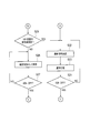
- FIG. 3 is a flowchart showing the dark current interruption method according to the present embodiment.
- FIG. 4 is a block diagram showing a main part of the dark current interrupting device according to the second embodiment.
- FIG. 5 is a first flowchart showing a dark current interruption method according to the second embodiment.
- FIG. 6 is a second flowchart showing the dark current interruption method according to the second embodiment.
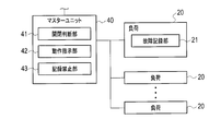
- FIG. 1 is a schematic configuration diagram of a dark current interrupting device 1 according to the present embodiment.
- the dark current interrupt device 1 includes a battery 10, a load 20, a fuse block 30, and a master unit 40.
- the battery 10 supplies power to the load 20.
- the load 20 is various devices mounted on the vehicle such as meters.
- the load 20 includes a number of audio devices that do not require power supply during vehicle transportation or storage.
- the fuse block 30 includes a large number of fuses 31 that protect the load 20 from a large current when a current exceeding the rating flows. The current from the battery 10 is supplied to each load 20 through the fuse block 30.
- the fuse block 30 includes a cut-off switch 32 for restricting power supply to some of the loads 20.
- the cut-off switch 32 is provided between the battery 10 and the load 20 and includes a short pin 32a.
- the short pin 32a cuts off the power supply to the load 20 when pulled out (opened) and supplies power to the load 20 when plugged in (closed).
- the short pin 32a is pulled out so that the current from the battery 10 is not supplied to some of the loads 20. Thereby, the dark current at the time of transportation or storage of the vehicle is cut off.
- the dark current interrupting device 1 has the following configuration.
- FIG. 2 is a block diagram showing a main part of the dark current interrupting device 1 according to the present embodiment.
- the master unit 40 includes an open / close determination unit (open / close determination unit) 41, an operation instruction unit (prohibition instruction unit) 42, and a recording prohibition unit (recording prohibition unit) 43.
- the load 20 includes a failure recording unit (failure recording unit) 21 that performs the above-described failure recording process.
- the failure recording unit 21 determines that the load 20 has failed when the load 20 does not operate, and records the fact.
- the open / close determining unit 41 determines that the cut-off switch 32 is open, that is, that the short pin 32a is pulled out. As shown in FIG. 1, the master unit 40 is connected to the battery 10 via a cutoff switch 32 and a signal line 33, and the open / close determination unit 41 is based on the voltage value input from the signal line 33. It can be determined whether the switch 32 is open or closed.
- the recording prohibition unit 43 When the open / close determination unit 41 determines that the cutoff switch 32 is open, the recording prohibition unit 43 performs power failure recording processing on the power from the battery 10 through another path C that does not pass through the cutoff switch 32. It supplies to the load 20 to perform.
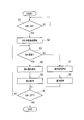
- FIG. 3 is a flowchart showing the dark current interruption method according to the present embodiment.
- the master unit 40 determines whether or not the ignition switch is turned on (S1). If it is determined that the ignition switch is not turned on (S1: NO), this process is repeated until it is determined that the ignition switch is turned on.
- the open / close determination unit 41 starts detecting whether the cut-off switch 32 is in an open state or a closed state (S2). Thereafter, the open / close determination unit 41 detects the state of the cutoff switch 32 until the ignition switch is turned off.
- the open / close determination unit 41 determines whether or not the cut-off switch 32 is in an open state (S3). If it is determined that the cut-off switch 32 is in the open state (S3: YES), the operation instruction unit 42 generates a prohibition signal instructing prohibition of the failure recording process (S4). Then, the recording prohibiting unit 43 executes a prohibiting process that prohibits the failure recording process (S5). That is, the recording prohibition unit 43 supplies power to the load 20 that performs the failure recording process through another path C. As a result, even if the short pin 32a is removed, power is supplied to the load 20 that performs the failure recording process, and the failure recording process is not performed. Further, since the power supply path is interrupted to the load 20 that does not perform the failure recording process, the dark current is also interrupted.
- the master unit 40 determines whether or not the ignition switch is turned off (S6). If it is determined that the ignition switch is not turned off (S6: NO), the process proceeds to step S3. On the other hand, when it is determined that the ignition switch has been turned off (S6: YES), the processing shown in FIG. 3 ends.
- the operation instruction unit 42 If it is determined that the cut-off switch 32 is not open (S3: NO), the operation instruction unit 42 generates a normal signal instructing a normal operation that does not prohibit the failure recording process (S7). Thereafter, the recording prohibition unit 43 does not execute the prohibition process for prohibiting the failure recording process, but executes the normal process (S8).
- the normal process As a result, when the user uses the vehicle and there is a failure in the load 20 and the power supply is cut off, failure information is recorded by the failure recording unit 21, and failure occurs from the failure information at the time of repair at a dealer or the like. The load 20 can be easily specified. Thereafter, the process proceeds to step S6 described above.
- the dark current interrupting device 1 and the dark current interrupting method according to the present embodiment when it is determined that the cut-off switch 32 is open, the power from the battery 10 is cut off. Is supplied to the load 20 via another route C that does not pass through, so that the failure recording unit 21 determines that a failure has occurred and prevents failure information from being recorded. For this reason, even if the short pin 32a is removed, power is continuously supplied to the load 20 that performs the failure recording process, and the failure recording process is not performed. On the other hand, for loads that are not subjected to failure recording processing, the power supply path is cut off and dark current is cut off. Therefore, according to the dark current interrupting device 1 and the dark current interrupting method according to the present embodiment, it is possible to eliminate the failure information erasing work and improve the dark current interrupting effect.
- a cut-off switch 32 for cutting off power supply to the load 20 or supplying power to the load 20 by inserting / removing the short pin 32a is provided.
- the load 20 that performs failure recording processing and the load 20 that does not perform failure recording processing are separated, and the load 20 and failure recording that performs failure recording processing are separated. It is also conceivable to provide a cut-off switch 32 for each load 20 that does not perform processing. Then, it is conceivable to remove the short pin 32a from the fuse block 32 of the load 20 that is not subjected to the failure recording process.
- the operator must determine the cut-off switch 32 to pull out the short pin 32a, and an error may occur in the operation of pulling out the short pin 32a.
- the cut-off switch 32 even if the cut-off switch 32 is provided, it is not necessary for the operator to determine the cut-off switch 32 to pull out the short pin 32a. Even if a device that cuts off the power supply path is provided, the dark current can be cut off appropriately.
- the dark current interrupting device and the dark current interrupting method according to the second embodiment are the same as those of the first embodiment, but the configuration and the processing method are partially different. Hereinafter, differences from the first embodiment will be described.
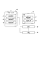
- FIG. 4 is a block diagram showing a main part of the dark current interrupting device 1 according to the second embodiment.
- the dark current interruption device 2 shown in FIG. 4 does not supply power to the load 20 that performs the failure recording process when the cut-off switch 32 is opened as in the first embodiment, but the load 20 that performs the failure recording process. The function for performing the failure recording process is prohibited.
- the operation instruction unit 42 transmits a prohibition signal for prohibiting the failure recording process to the load 20.
- the load 20 includes a recording prohibition unit (recording prohibiting means) 22.
- the recording prohibition unit 22 of the load 20 receives the prohibition signal from the operation instruction unit 42, the recording unit 21 prohibits the failure recording unit 21 from determining failure and recording failure information. That is, the recording prohibition unit 22 masks the function of the failure recording process by the failure recording unit 21.
- the master unit 40 includes an abnormality detection unit (abnormality detection means) 44 instead of the recording prohibition unit 43.
- the abnormality detection unit 44 detects the abnormality of the cutoff switch 32. Details of the abnormality detection unit 43 will be described later.
- the recording prohibition unit 22 does not execute the operation of prohibiting the failure recording process when the abnormality detection unit 43 detects the abnormality of the cutoff switch 32. For this reason, when the abnormality of the cut-off switch 32 is erroneously determined to be the opening of the cut-off switch 32 and the failure recording process should be originally performed, the failure recording process is not prohibited and is normally performed. Can be executed.
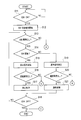
- FIG. 5 and 6 are flowcharts showing the dark current interruption method according to this embodiment. Note that the processing in steps S11 and S12 shown in FIG. 5 is the same as that in steps S1 and S2 shown in FIG.
- step S13 the abnormality determination unit 43 determines whether or not an abnormality has occurred in the cutoff switch 32 (S13).
- An example of a method for determining abnormality of the cut-off switch 32 will be described.
- the failure recording process is prohibited (masked) when the cut-off switch 32 is opened. Therefore, for example, if there is no failure in the load 20, the failure recording process is masked when the cut-off switch 32 is opened, and the normal determination is executed and the failure information is recorded when the cut-off switch 32 is closed. There is nothing to do. Further, when failure information is recorded for only one of the loads 20, a normal determination is performed and failure information for the load 20 is recorded.
- the abnormality determination unit 43 determines that the cutoff switch 32 is abnormal when a large number of pieces of failure information are recorded.
- the open / close determining unit 41 determines whether or not the cut-off switch 32 is in an open state (S14).
- the operation instruction unit 42 transmits a prohibition signal instructing prohibition of the failure recording process (S15). At this time, the operation instruction unit 42 selects the load 20 having the function of performing the failure recording process and transmits a prohibition signal.
- the master unit 40 determines whether or not there is a communication abnormality (S16). This is because when the communication abnormality occurs, the prohibition signal transmitted in step S5 is not received by the load 20 and the failure recording process is not masked.
- the load 20 when receiving a signal from the operation instruction unit 42, the load 20 returns a signal indicating that the load has been received to the master unit 40. Therefore, the master unit 40 determines that there is no communication abnormality when a response is received from the load 20, and determines that a communication error has occurred when there is no response from the load 20.
- the recording prohibition unit 22 executes a prohibition process for prohibiting the failure recording process (S17). Thereby, even if it is the load 20 which performs a failure recording process, a dark current can be interrupted
- the master unit 40 determines whether or not the ignition switch is turned off (S18). If it is determined that the ignition switch is not turned off (S18: NO), the process proceeds to step S13. On the other hand, when it is determined that the ignition switch is turned off (S18: YES), the processing shown in FIGS. 5 and 6 ends.
- the operation instruction unit 42 transmits a normal signal instructing a normal operation that does not prohibit the failure recording process (S19). Thereafter, the master unit 40 determines whether or not there is a communication abnormality (S20). The method for determining the communication abnormality is the same as in step S16.
- the recording prohibition unit 22 does not execute the prohibition process for prohibiting the failure recording process, and the load 20 executes a normal process (S21).
- the failure information is recorded by the failure recording unit 21, and the faulty load 20 is easily identified from the failure information at the time of repair by a dealer or the like. can do. Thereafter, the process proceeds to step S18 described above.
- the process proceeds to step S22 in FIG. Then, the operation instruction unit 42 transmits a normal signal instructing a normal operation that does not prohibit the failure recording process (S22). Thereby, the recording prohibition unit 22 does not execute the prohibition process for prohibiting the failure recording process, and the load 20 executes the normal process (S23).
- the reason for executing the normal processing is as follows. If the cut-off switch 32 is abnormal, the load 20 is not supplied with power. For this reason, the load 20 performs the failure recording process when the normal process is executed. In addition, since the cutoff switch 32 is abnormal, failure information is recorded for a large number of loads 20. As a result, a dealer or the like can determine that the cut-off switch 32 is not abnormal from a large number of pieces of failure information, but can replace or repair the cut-off switch 32.
- step S24 the master unit 40 determines whether or not the ignition switch is turned off (S24). If it is determined that the ignition switch is not turned off (S24: NO), the process proceeds to step S22. On the other hand, if it is determined that the ignition switch has been turned off (S24: YES), the processing shown in FIGS. 5 and 6 ends.
- step S16 and step S20 shown in FIG. 5 If it is determined in step S16 and step S20 shown in FIG. 5 that there is a communication abnormality (S16, S20: NO), the process proceeds to step S25 in FIG. Then, the load 20 determines whether or not a signal indicating the state of the cutoff switch 32 has not been received (S25). That is, the load 20 determines whether or not the prohibition signal shown in step S15 or the normal signal shown in step S19 has been received once in the past.
- step S22 If it is determined that a signal indicating the state of the cut-off switch 32 has not been received (S25: YES), the process proceeds to step S22. On the other hand, when it is determined that it has not been received (S25: NO), the failure recording unit 21 holds the failure information of the load 20 before the occurrence of the communication abnormality as a confirmed state (S26). Thereafter, the master unit 40 determines whether or not the ignition switch is turned off (S27). If it is determined that the ignition switch is not turned off (S27: NO), the process proceeds to step S26. On the other hand, when it is determined that the ignition switch is turned off (S27: YES), the processing shown in FIGS. 5 and 6 ends.
- the failure recording unit 21 determines that a failure has occurred. Therefore, even if the power supply to the load 20 that performs the failure recording process is cut off, the failure is not recorded, and the operation of deleting the failure information is not necessary when the vehicle is sold. . As a result, the dark current can be cut off also for the load 20 that performs the failure recording process, and the dark current cut-off effect can be improved.
- the recording prohibition unit 22 does not execute the prohibition operation of the failure recording process when the abnormality detection unit 43 detects an abnormality of the cutoff switch 32. For this reason, when the abnormality of the cut-off switch 32 is erroneously determined to be the opening of the cut-off switch 32 and the failure recording process must be originally performed, the failure recording process is not prohibited and the failure recording process is normally performed. Can be executed.
- the recorded information regarding the failure of the load 20 is held in a fixed state, so that failure information is not rewritten due to a communication abnormality, and communication is performed. It is possible to prevent an operation such as deleting failure information from occurring when an abnormality is resolved.
- the cut-off switch 32 is provided to cut off the power supply to the load 20 or supply the power to the load 20 by inserting / removing the short pin 32a, the dark current can be appropriately adjusted as in the first embodiment. Can be cut off.
- the present invention is applicable to a dark current interrupting device and method for interrupting dark current of a vehicle on which a large number of electrical components are mounted.
Landscapes
- Engineering & Computer Science (AREA)
- Mechanical Engineering (AREA)
- Emergency Protection Circuit Devices (AREA)
- Charge And Discharge Circuits For Batteries Or The Like (AREA)
- Power Engineering (AREA)
Abstract
A dark current cutoff device (1) comprises: a battery (10) for supplying electrical power to a load (20); a cutoff switch (32) provided between the battery (10) and the load (20) to cut off the supply of electrical power to the load (20) when open and to allow electrical power to be supplied to the load (20) when closed; a failure recording part (21) for determining that a failure has occurred in the load (20) when the load (20) does not operate, and recording the failure; an open/close determining part (41) for determining that the cutoff switch (32) is open; and a recording prohibiting part (22) for prohibiting the failure recording part (21) from determining and recording that a failure has occurred when the cutoff switch (32) is determined by the open/close determining part (41) to be open.
Description
本発明は、暗電流遮断装置及び暗電流遮断方法に関する。
The present invention relates to a dark current interrupting device and a dark current interrupting method.
近年、車両では電装品が増加の傾向にあり、車両の輸送中や保管中において暗電流が増加する傾向にある。このため、車両の輸送中や保管中にバッテリが上がり易くなってしまう。そこで、車両の輸送中や保管中にバッテリが上がってしまうことを防止するため、負荷とバッテリとの間に設けられたヒューズのショートピン等を抜いておく技術が提案されている(例えば特許文献1,2参照)。また、負荷とバッテリとの間にリレーを設け、このリレーを開放するものが提案されている(例えば特許文献3参照)。
In recent years, electrical components have been increasing in vehicles, and dark current has been increasing during transportation and storage of vehicles. For this reason, the battery is likely to rise during transportation or storage of the vehicle. Therefore, in order to prevent the battery from going up during transportation or storage of the vehicle, a technique has been proposed in which a short pin of a fuse provided between the load and the battery is removed (for example, patent document). 1 and 2). Further, there has been proposed a relay that is provided between a load and a battery and the relay is opened (see, for example, Patent Document 3).
ここで、負荷には、故障情報の記録を行うものが存在する。すなわち、負荷には、電力供給が行われず正常に作動できない場合、故障と判断してその旨を表す故障情報を記録するものがある。しかし、従来装置では、暗電流を遮断するためにショートピン等を抜いた場合、故障記録処理を行う機能を有する負荷については電力供給が遮断されたことにより故障記録処理を行ってしまう。このように故障記録処理が行われてしまうと、ディーラ等では車両の販売時に故障情報を消去する作業が必要となってしまう。一方、故障記録処理がされないようにショートピン等を抜かないとなると、暗電流を遮断できず、暗電流の遮断効果が低減されてしまう。
Here, there is a load that records failure information. That is, there is a load that records failure information indicating that it is determined to be a failure when power supply is not performed and the load cannot be operated normally. However, in the conventional apparatus, when a short pin or the like is removed to cut off the dark current, the fault recording process is performed for the load having the function of performing the fault recording process because the power supply is cut off. If the failure recording process is performed in this way, a dealer or the like needs to delete the failure information when the vehicle is sold. On the other hand, if the short pin or the like is not removed so that the failure recording process is not performed, the dark current cannot be interrupted, and the dark current interrupting effect is reduced.
本発明はこのような従来の課題を解決するためになされたものであり、その目的とするところは、故障情報の消去作業を不要とし、且つ、暗電流の遮断効果について向上を図ることが可能な暗電流遮断装置及び暗電流遮断方法を提供することにある。
The present invention has been made to solve such a conventional problem. The object of the present invention is to eliminate the failure information erasing operation and to improve the dark current blocking effect. An object of the present invention is to provide a dark current interruption device and a dark current interruption method.
本発明の第一の態様に係る暗電流遮断装置において故障記録手段は、負荷が作動しない場合に負荷の故障と判断して記録する。また、開閉判断手段は、バッテリと負荷との間に設けられて開放時に負荷への電力供給を遮断すると共に閉鎖時に負荷へ電力を供給させる開閉手段が開放されていることを判断する。記録禁止手段は、開閉手段が開放されていると判断された場合に、故障記録手段により故障と判断されて記録されることを禁止する。
In the dark current interrupting device according to the first aspect of the present invention, the failure recording means records and records a load failure when the load does not operate. The open / close determining means determines that the open / close means provided between the battery and the load for cutting off power supply to the load when opened and supplying power to the load when closed is open. The recording prohibiting means prohibits recording when the failure recording means determines that there is a failure when it is determined that the opening / closing means is open.
本発明の第二の態様に係る暗電流遮断装置において故障記録手段は、負荷が作動しない場合に負荷の故障と判断して記録する。また、開閉判断手段は、バッテリと負荷との間に設けられて開放時に負荷への電力供給を遮断すると共に閉鎖時に負荷へ電力を供給させる開閉手段が開放されていることを判断する。記録禁止手段は、開閉手段が開放されていると判断された場合に、バッテリからの電力を開閉手段を介さない別経路により負荷に供給して、故障記録手段により故障と判断されて記録されないようにする。
In the dark current interrupting device according to the second aspect of the present invention, the failure recording means records and records a load failure when the load does not operate. The open / close determining means determines that the open / close means provided between the battery and the load for cutting off power supply to the load when opened and supplying power to the load when closed is open. When it is determined that the opening / closing means is open, the recording prohibiting means supplies power from the battery to the load through another route not via the opening / closing means, so that the failure recording means determines that a failure has occurred and is not recorded. To.
以下、本発明の好適な実施形態を図面に基づいて説明する。図1は、本実施形態に係る暗電流遮断装置1の概略構成図である。図1に示すように、暗電流遮断装置1は、バッテリ10と、負荷20と、ヒューズブロック30と、マスターユニット40とから構成されている。
DESCRIPTION OF EXEMPLARY EMBODIMENTS Hereinafter, preferred embodiments of the invention will be described with reference to the drawings. FIG. 1 is a schematic configuration diagram of a dark current interrupting device 1 according to the present embodiment. As shown in FIG. 1, the dark current interrupt device 1 includes a battery 10, a load 20, a fuse block 30, and a master unit 40.
バッテリ10は、負荷20に対して電力供給を行うものである。負荷20は、メータ類など、車両に搭載される各種機器である。この負荷20には、車両輸送時や保管時において電力供給の必要が無いオーディオ機器等のものが多数ある。ヒューズブロック30は、定格以上の電流が流れた場合に大電流から負荷20を保護するヒューズ31を多数備えたものである。バッテリ10からの電流はこのヒューズブロック30を介して各負荷20に供給される。
The battery 10 supplies power to the load 20. The load 20 is various devices mounted on the vehicle such as meters. The load 20 includes a number of audio devices that do not require power supply during vehicle transportation or storage. The fuse block 30 includes a large number of fuses 31 that protect the load 20 from a large current when a current exceeding the rating flows. The current from the battery 10 is supplied to each load 20 through the fuse block 30.
また、ヒューズブロック30は、負荷20のうち一部の負荷20に対して電力供給を制限するためのカットオフスイッチ32を備えている。このカットオフスイッチ32は、バッテリ10と負荷20との間に設けられており、ショートピン32aを備えている。ショートピン32aは、引き抜き時(開放時)に負荷20への電力供給を遮断すると共に差し込み時(閉鎖時)に負荷20へ電力を供給させるものである。一般に車両の輸送時や保管時においては、ショートピン32aが引き抜かれており、バッテリ10からの電流が一部の負荷20に対して供給されないようになっている。これにより、車両の輸送時や保管時における暗電流が遮断されることとなる。
Further, the fuse block 30 includes a cut-off switch 32 for restricting power supply to some of the loads 20. The cut-off switch 32 is provided between the battery 10 and the load 20 and includes a short pin 32a. The short pin 32a cuts off the power supply to the load 20 when pulled out (opened) and supplies power to the load 20 when plugged in (closed). Generally, when the vehicle is transported or stored, the short pin 32a is pulled out so that the current from the battery 10 is not supplied to some of the loads 20. Thereby, the dark current at the time of transportation or storage of the vehicle is cut off.
しかし、負荷20には、故障記録処理を行うものが存在する。すなわち、負荷20には、電力供給が行われず正常に作動できない場合、故障と判断してその旨を表す故障情報を記録するものがある。このため、ショートピン32aを引き抜いてしまうと、このような負荷20は故障記録処理を行ってしまう。故に、ディーラ等は、車両販売時に故障情報を消去しなければならなくなってしまう。一方、このような負荷20に対して輸送時や保管時においてもバッテリ10との接続関係を維持すると暗電流が流れてしまい、暗電流の遮断効果の低下につながってしまう。そこで、本実施形態に係る暗電流遮断装置1は以下の構成を備えている。
However, some loads 20 perform failure recording processing. That is, when the power supply is not performed and the load 20 cannot operate normally, there is a load 20 that determines failure and records failure information indicating that fact. For this reason, when the short pin 32a is pulled out, such a load 20 performs a failure recording process. Therefore, the dealer or the like has to delete the failure information when selling the vehicle. On the other hand, if the connection relationship with the battery 10 is maintained for such a load 20 during transportation or storage, dark current flows, leading to a reduction in dark current blocking effect. Therefore, the dark current interrupting device 1 according to the present embodiment has the following configuration.
図2は、本実施形態に係る暗電流遮断装置1の要部を示すブロック図である。図2に示すように、マスターユニット40は、開閉判断部(開閉判断手段)41と、動作指示部(禁止指示手段)42と、記録禁止部(記録禁止手段)43とを備えている。また、負荷20は、上述した故障記録処理を行う故障記録部(故障記録手段)21を備えている。
FIG. 2 is a block diagram showing a main part of the dark current interrupting device 1 according to the present embodiment. As shown in FIG. 2, the master unit 40 includes an open / close determination unit (open / close determination unit) 41, an operation instruction unit (prohibition instruction unit) 42, and a recording prohibition unit (recording prohibition unit) 43. The load 20 includes a failure recording unit (failure recording unit) 21 that performs the above-described failure recording process.
故障記録部21は、負荷20が作動しない場合に負荷20の故障と判断してその旨を記録するものである。開閉判断部41は、カットオフスイッチ32が開放されていること、すなわちショートピン32aが引き抜かれていることを判断するものである。図1に示すように、マスターユニット40はカットオフスイッチ32及び信号線33を介してバッテリ10と接続されており、開閉判断部41は信号線33から入力される電圧値に基づいて、カットオフスイッチ32が開放状態であるか閉鎖状態であるかを判断することができる。
The failure recording unit 21 determines that the load 20 has failed when the load 20 does not operate, and records the fact. The open / close determining unit 41 determines that the cut-off switch 32 is open, that is, that the short pin 32a is pulled out. As shown in FIG. 1, the master unit 40 is connected to the battery 10 via a cutoff switch 32 and a signal line 33, and the open / close determination unit 41 is based on the voltage value input from the signal line 33. It can be determined whether the switch 32 is open or closed.
記録禁止部43は、開閉判断部41によりカットオフスイッチ32が開放されていると判断された場合に、カットオフスイッチ32を介さない別経路Cにより、バッテリ10からの電力を、故障記録処理を行う負荷20に供給するものである。
When the open / close determination unit 41 determines that the cutoff switch 32 is open, the recording prohibition unit 43 performs power failure recording processing on the power from the battery 10 through another path C that does not pass through the cutoff switch 32. It supplies to the load 20 to perform.
このような構成により、故障記録処理を行う負荷20であってもカットオフスイッチ32の開放時に故障情報を記録することなく、車両の販売時に故障情報を消去する作業が不要とすることができる。
With such a configuration, even if the load 20 performs the failure recording process, the failure information is not recorded when the cut-off switch 32 is opened, and the operation of deleting the failure information when the vehicle is sold can be eliminated.
次に、フローチャートを参照して、本実施形態に係る暗電流遮断方法について説明する。図3は、本実施形態に係る暗電流遮断方法を示すフローチャートである。
Next, the dark current interruption method according to the present embodiment will be described with reference to a flowchart. FIG. 3 is a flowchart showing the dark current interruption method according to the present embodiment.
まず、図3に示すように、マスターユニット40は、イグニッションスイッチがオンされたか否かを判断する(S1)。イグニッションスイッチがオンされていないと判断した場合(S1:NO)、イグニッションスイッチがオンされたと判断されるまで、この処理は繰り返される。
First, as shown in FIG. 3, the master unit 40 determines whether or not the ignition switch is turned on (S1). If it is determined that the ignition switch is not turned on (S1: NO), this process is repeated until it is determined that the ignition switch is turned on.
一方、イグニッションスイッチがオンされたと判断した場合(S1:YES)、開閉判断部41は、カットオフスイッチ32が開放状態であるか閉鎖状態であるかについて検出を開始する(S2)。以後、開閉判断部41は、イグニッションスイッチがオフされるまで、カットオフスイッチ32の状態を検出することとなる。
On the other hand, when it is determined that the ignition switch is turned on (S1: YES), the open / close determination unit 41 starts detecting whether the cut-off switch 32 is in an open state or a closed state (S2). Thereafter, the open / close determination unit 41 detects the state of the cutoff switch 32 until the ignition switch is turned off.
その後、開閉判断部41は、カットオフスイッチ32が開放状態であるか否かを判断する(S3)。カットオフスイッチ32が開放状態であると判断した場合(S3:YES)、動作指示部42は、故障記録処理の禁止を指示する禁止信号を発生させる(S4)。そして、記録禁止部43は、故障記録処理を禁止する禁止処理を実行する(S5)。すなわち、記録禁止部43は、別経路Cにより故障記録処理を行う負荷20に対して電力を供給する。これにより、たとえショートピン32aを抜いていたとしても、故障記録処理を行う負荷20に対して電力が供給されて故障記録処理がされないこととなる。また、故障記録処理を行わない負荷20には電力の供給経路が遮断されているため、暗電流についても遮断されることとなる。
Thereafter, the open / close determination unit 41 determines whether or not the cut-off switch 32 is in an open state (S3). If it is determined that the cut-off switch 32 is in the open state (S3: YES), the operation instruction unit 42 generates a prohibition signal instructing prohibition of the failure recording process (S4). Then, the recording prohibiting unit 43 executes a prohibiting process that prohibits the failure recording process (S5). That is, the recording prohibition unit 43 supplies power to the load 20 that performs the failure recording process through another path C. As a result, even if the short pin 32a is removed, power is supplied to the load 20 that performs the failure recording process, and the failure recording process is not performed. Further, since the power supply path is interrupted to the load 20 that does not perform the failure recording process, the dark current is also interrupted.
次いで、マスターユニット40は、イグニッションスイッチがオフされたか否かを判断する(S6)。イグニッションスイッチがオフされていないと判断した場合(S6:NO)、処理はステップS3に移行する。一方、イグニッションスイッチがオフされたと判断した場合(S6:YES)、図3に示す処理は終了する。
Next, the master unit 40 determines whether or not the ignition switch is turned off (S6). If it is determined that the ignition switch is not turned off (S6: NO), the process proceeds to step S3. On the other hand, when it is determined that the ignition switch has been turned off (S6: YES), the processing shown in FIG. 3 ends.
また、カットオフスイッチ32が開放状態でないと判断した場合(S3:NO)、動作指示部42は、故障記録処理を禁止しない通常動作を指示する通常信号を発生させる(S7)。その後、記録禁止部43は故障記録処理を禁止する禁止処理を実行せず、通常処理を実行する(S8)。これにより、ユーザによる車両使用時において負荷20に故障があって電力供給が断たれた場合、故障記録部21により故障情報が記録されることとなり、ディーラ等における修理時に故障情報から故障している負荷20を容易に特定することができる。その後、処理は上記したステップS6に移行する。
If it is determined that the cut-off switch 32 is not open (S3: NO), the operation instruction unit 42 generates a normal signal instructing a normal operation that does not prohibit the failure recording process (S7). Thereafter, the recording prohibition unit 43 does not execute the prohibition process for prohibiting the failure recording process, but executes the normal process (S8). As a result, when the user uses the vehicle and there is a failure in the load 20 and the power supply is cut off, failure information is recorded by the failure recording unit 21, and failure occurs from the failure information at the time of repair at a dealer or the like. The load 20 can be easily specified. Thereafter, the process proceeds to step S6 described above.
このようにして、本実施形態に係る暗電流遮断装置1及び暗電流遮断方法によれば、カットオフスイッチ32が開放されていると判断された場合に、バッテリ10からの電力をカットオフスイッチ32を介さない別経路Cにより負荷20に供給して、故障記録部21により故障と判断されて故障情報が記録されないようにする。このため、ショートピン32aを抜いたとしても故障記録処理を行う負荷20については電力が供給され続けることとなり、故障記録処理が行われないこととなる。一方、故障記録処理を行わない負荷については電力供給路が遮断されて暗電流が遮断されることとなる。従って、本実施形態に係る暗電流遮断装置1及び暗電流遮断方法によれば、故障情報の消去作業を不要とし、且つ、暗電流の遮断効果について向上を図ることができる。
Thus, according to the dark current interrupting device 1 and the dark current interrupting method according to the present embodiment, when it is determined that the cut-off switch 32 is open, the power from the battery 10 is cut off. Is supplied to the load 20 via another route C that does not pass through, so that the failure recording unit 21 determines that a failure has occurred and prevents failure information from being recorded. For this reason, even if the short pin 32a is removed, power is continuously supplied to the load 20 that performs the failure recording process, and the failure recording process is not performed. On the other hand, for loads that are not subjected to failure recording processing, the power supply path is cut off and dark current is cut off. Therefore, according to the dark current interrupting device 1 and the dark current interrupting method according to the present embodiment, it is possible to eliminate the failure information erasing work and improve the dark current interrupting effect.
また、ショートピン32aを抜き差しすることにより、負荷20への電力供給を遮断したり、負荷20へ電力供給したりするカットオフスイッチ32を備える。ここで、本実施形態によらず暗電流を遮断する手法として、例えば故障記録処理を行う負荷20と故障記録処理を行わない負荷20とを分けておき、故障記録処理を行う負荷20と故障記録処理を行わない負荷20とのそれぞれにカットオフスイッチ32を設けることも考えられる。そして、故障記録処理を行わない負荷20のヒューズブロック32についてショートピン32aを抜くことが考えられる。しかし、この場合、作業者がショートピン32aを抜くべきカットオフスイッチ32を判断しなければならず、ショートピン32aを抜く作業において誤りが発生する可能性がある。これに対して、本実施形態ではたとえカットオフスイッチ32を備えていたとしても、作業者がショートピン32aを抜くべきカットオフスイッチ32を判断する必要がなく、カットオフスイッチ32のような手作業にて電力供給路を遮断するものを備えていたとしても適切に暗電流を遮断することができる。
Further, a cut-off switch 32 for cutting off power supply to the load 20 or supplying power to the load 20 by inserting / removing the short pin 32a is provided. Here, as a technique for interrupting the dark current regardless of the present embodiment, for example, the load 20 that performs failure recording processing and the load 20 that does not perform failure recording processing are separated, and the load 20 and failure recording that performs failure recording processing are separated. It is also conceivable to provide a cut-off switch 32 for each load 20 that does not perform processing. Then, it is conceivable to remove the short pin 32a from the fuse block 32 of the load 20 that is not subjected to the failure recording process. However, in this case, the operator must determine the cut-off switch 32 to pull out the short pin 32a, and an error may occur in the operation of pulling out the short pin 32a. In contrast, in this embodiment, even if the cut-off switch 32 is provided, it is not necessary for the operator to determine the cut-off switch 32 to pull out the short pin 32a. Even if a device that cuts off the power supply path is provided, the dark current can be cut off appropriately.
次に、本発明の第2実施形態を説明する。第2実施形態に係る暗電流遮断装置及び暗電流遮断方法は、第1実施形態のものと同様であるが、構成及び処理方法が一部異なっている。以下、第1実施形態との相違点について説明する。
Next, a second embodiment of the present invention will be described. The dark current interrupting device and the dark current interrupting method according to the second embodiment are the same as those of the first embodiment, but the configuration and the processing method are partially different. Hereinafter, differences from the first embodiment will be described.
図4は、第2実施形態に係る暗電流遮断装置1の要部を示すブロック図である。図4に示す暗電流遮断装置2は、第1実施形態のようにカットオフスイッチ32の開放時に故障記録処理を行う負荷20に対して電力を供給するのではなく、故障記録処理を行う負荷20に対して故障記録処理を行う機能を禁止させることとしている。
FIG. 4 is a block diagram showing a main part of the dark current interrupting device 1 according to the second embodiment. The dark current interruption device 2 shown in FIG. 4 does not supply power to the load 20 that performs the failure recording process when the cut-off switch 32 is opened as in the first embodiment, but the load 20 that performs the failure recording process. The function for performing the failure recording process is prohibited.
具体的に第2実施形態において、動作指示部42は、開閉判断部41によりカットオフスイッチ32が開放されていると判断された場合、故障記録処理を禁止する旨の禁止信号を負荷20に送信する。また、負荷20は、記録禁止部(記録禁止手段)22を備えている。負荷20の記録禁止部22は、動作指示部42からの禁止信号を受信すると、故障記録部21により故障と判断されて故障情報が記録されることを禁止することとなる。すなわち、記録禁止部22は、故障記録部21による故障記録処理の機能をマスクすることとなる。
Specifically, in the second embodiment, when the open / close determination unit 41 determines that the cut-off switch 32 is open, the operation instruction unit 42 transmits a prohibition signal for prohibiting the failure recording process to the load 20. To do. The load 20 includes a recording prohibition unit (recording prohibiting means) 22. When the recording prohibition unit 22 of the load 20 receives the prohibition signal from the operation instruction unit 42, the recording unit 21 prohibits the failure recording unit 21 from determining failure and recording failure information. That is, the recording prohibition unit 22 masks the function of the failure recording process by the failure recording unit 21.
さらに、第2実施形態においてマスターユニット40は、記録禁止部43に代えて異常検出部(異常検出手段)44を備えている。異常検出部44は、異常検出部43はカットオフスッチ32の異常を検出するものである。この異常検出部43についての詳細は後述する。
Furthermore, in the second embodiment, the master unit 40 includes an abnormality detection unit (abnormality detection means) 44 instead of the recording prohibition unit 43. The abnormality detection unit 44 detects the abnormality of the cutoff switch 32. Details of the abnormality detection unit 43 will be described later.
また、記録禁止部22は、異常検出部43によりカットオフスッチ32の異常が検出された場合、故障記録処理を禁止する動作を実行しない。このため、カットオフスイッチ32の異常をカットオフスイッチ32の開放と誤って判断して、本来故障記録処理を行わなければならない場合に故障記録処理を禁止してしまうことなく、正常に故障記録処理を実行することができる。
Further, the recording prohibition unit 22 does not execute the operation of prohibiting the failure recording process when the abnormality detection unit 43 detects the abnormality of the cutoff switch 32. For this reason, when the abnormality of the cut-off switch 32 is erroneously determined to be the opening of the cut-off switch 32 and the failure recording process should be originally performed, the failure recording process is not prohibited and is normally performed. Can be executed.
次に、フローチャートを参照して、第2実施形態に係る暗電流遮断方法について説明する。図5及び図6は、本実施形態に係る暗電流遮断方法を示すフローチャートである。なお、図5に示すステップS11,S12の処理は図3に示したステップS1,S2と同様であるため、説明を省略する。
Next, a dark current interruption method according to the second embodiment will be described with reference to a flowchart. 5 and 6 are flowcharts showing the dark current interruption method according to this embodiment. Note that the processing in steps S11 and S12 shown in FIG. 5 is the same as that in steps S1 and S2 shown in FIG.
ステップS13において異常判断部43は、カットオフスイッチ32に異常が発生していないか否かを判断する(S13)。カットオフスイッチ32の異常の判断方法について一例を説明する。まず、本実施形態では上記したように、カットオフスイッチ32の開放時に故障記録処理が禁止(マスク)される。このため、例えば、負荷20に故障が無ければ、カットオフスイッチ32の開放時には故障記録処理がマスクされると共に、カットオフスイッチ32の閉鎖時には通常の通りの判断が実行されて故障情報が記録されることがない。また、負荷20の1つだけについて故障情報が記録されている場合、通常通りの判断が実行されてその負荷20についての故障情報が記録される。しかし、多数の負荷20について故障情報の記録がされている場合は、多数の負荷20それぞれの故障とは考え難く、カットオフスイッチ32に異常が発生している判断することが妥当といえる。このため、異常判断部43は、このような多数の故障情報の記録がされている場合に、カットオフスイッチ32の異常であると判断する。
In step S13, the abnormality determination unit 43 determines whether or not an abnormality has occurred in the cutoff switch 32 (S13). An example of a method for determining abnormality of the cut-off switch 32 will be described. First, as described above, in this embodiment, the failure recording process is prohibited (masked) when the cut-off switch 32 is opened. Therefore, for example, if there is no failure in the load 20, the failure recording process is masked when the cut-off switch 32 is opened, and the normal determination is executed and the failure information is recorded when the cut-off switch 32 is closed. There is nothing to do. Further, when failure information is recorded for only one of the loads 20, a normal determination is performed and failure information for the load 20 is recorded. However, when failure information is recorded for a large number of loads 20, it is difficult to consider a failure of each of the large numbers of loads 20, and it can be said that it is appropriate to determine that an abnormality has occurred in the cutoff switch 32. For this reason, the abnormality determination unit 43 determines that the cutoff switch 32 is abnormal when a large number of pieces of failure information are recorded.
カットオフスイッチ32に異常が発生していないと判断した場合(S13:YES)、開閉判断部41は、カットオフスイッチ32が開放状態であるか否かを判断する(S14)。カットオフスイッチ32が開放状態であると判断した場合(S14:YES)、動作指示部42は、故障記録処理の禁止を指示する禁止信号を送信する(S15)。このとき、動作指示部42は、故障記録処理を行う機能を有する負荷20を選別して禁止信号を送信する。
When it is determined that no abnormality has occurred in the cut-off switch 32 (S13: YES), the open / close determining unit 41 determines whether or not the cut-off switch 32 is in an open state (S14). When it is determined that the cutoff switch 32 is in the open state (S14: YES), the operation instruction unit 42 transmits a prohibition signal instructing prohibition of the failure recording process (S15). At this time, the operation instruction unit 42 selects the load 20 having the function of performing the failure recording process and transmits a prohibition signal.
その後、マスターユニット40は、通信異常がないか否かを判断する(S16)。通信異常が発生していると、ステップS5において送信した禁止信号が負荷20に受信されず、故障記録処理がマスクされないためである。なお、本実施形態において負荷20は、動作指示部42からの信号を受信すると、受信した旨の信号をマスターユニット40に返信する。よって、マスターユニット40は、負荷20から返信があった場合に通信異常がないと判断し、負荷20からの返信がなかった場合に通信異常が発生していると判断する。
Thereafter, the master unit 40 determines whether or not there is a communication abnormality (S16). This is because when the communication abnormality occurs, the prohibition signal transmitted in step S5 is not received by the load 20 and the failure recording process is not masked. In this embodiment, when receiving a signal from the operation instruction unit 42, the load 20 returns a signal indicating that the load has been received to the master unit 40. Therefore, the master unit 40 determines that there is no communication abnormality when a response is received from the load 20, and determines that a communication error has occurred when there is no response from the load 20.
通信異常がなかった場合(S16:YES)、記録禁止部22は、故障記録処理を禁止する禁止処理を実行する(S17)。これにより、故障記録処理を行う負荷20であっても、電力が供給されていないときに故障情報の記録がされることなく、ショートピン32aを抜いておくことにより暗電流を遮断することができる。
If there is no communication abnormality (S16: YES), the recording prohibition unit 22 executes a prohibition process for prohibiting the failure recording process (S17). Thereby, even if it is the load 20 which performs a failure recording process, a dark current can be interrupted | blocked by removing the short pin 32a, without recording failure information, when electric power is not supplied. .
次いで、マスターユニット40は、イグニッションスイッチがオフされたか否かを判断する(S18)。イグニッションスイッチがオフされていないと判断した場合(S18:NO)、処理はステップS13に移行する。一方、イグニッションスイッチがオフされたと判断した場合(S18:YES)、図5及び図6に示す処理は終了する。
Next, the master unit 40 determines whether or not the ignition switch is turned off (S18). If it is determined that the ignition switch is not turned off (S18: NO), the process proceeds to step S13. On the other hand, when it is determined that the ignition switch is turned off (S18: YES), the processing shown in FIGS. 5 and 6 ends.
また、カットオフスイッチ32が開放状態でないと判断した場合(S14:NO)、動作指示部42は、故障記録処理を禁止しない通常動作を指示する通常信号を送信する(S19)。その後、マスターユニット40は、通信異常がないか否かを判断する(S20)。通信異常の判断方法はステップS16と同じである。
If it is determined that the cutoff switch 32 is not in the open state (S14: NO), the operation instruction unit 42 transmits a normal signal instructing a normal operation that does not prohibit the failure recording process (S19). Thereafter, the master unit 40 determines whether or not there is a communication abnormality (S20). The method for determining the communication abnormality is the same as in step S16.
そして、通信異常がなかった場合(S20:YES)、記録禁止部22は故障記録処理を禁止する禁止処理を実行せず、負荷20は通常の処理を実行する(S21)。これにより、ユーザによる車両使用時において負荷20に故障があった場合、故障記録部21により故障情報が記録されることとなり、ディーラ等における修理時に故障情報から故障している負荷20を容易に特定することができる。その後、処理は上記したステップS18に移行する。
If there is no communication abnormality (S20: YES), the recording prohibition unit 22 does not execute the prohibition process for prohibiting the failure recording process, and the load 20 executes a normal process (S21). As a result, if there is a failure in the load 20 when the user uses the vehicle, the failure information is recorded by the failure recording unit 21, and the faulty load 20 is easily identified from the failure information at the time of repair by a dealer or the like. can do. Thereafter, the process proceeds to step S18 described above.
ところで、カットオフスイッチ32の異常があった場合(S13:NO)、処理は図6のステップS22に移行する。そして、動作指示部42は、故障記録処理を禁止しない通常動作を指示する通常信号を送信する(S22)。これにより、記録禁止部22は故障記録処理を禁止する禁止処理を実行せず、負荷20は通常の処理を実行する(S23)。
Incidentally, if there is an abnormality in the cut-off switch 32 (S13: NO), the process proceeds to step S22 in FIG. Then, the operation instruction unit 42 transmits a normal signal instructing a normal operation that does not prohibit the failure recording process (S22). Thereby, the recording prohibition unit 22 does not execute the prohibition process for prohibiting the failure recording process, and the load 20 executes the normal process (S23).
ここで、通常の処理を実行する理由は以下の通りである。カットオフスイッチ32に異常があった場合、負荷20には電力供給がされないこととなる。このため、通常処理実行時には負荷20は故障記録処理を行うこととなる。しかも、カットオフスイッチ32の異常であることから多数の負荷20について故障情報の記録が行われる。これにより、ディーラ等では多数の故障情報から多数の負荷20の個別の故障ではなくカットオフスイッチ32の異常であると判断でき、カットオフスイッチ32の交換や修理等を行うことができる。
Here, the reason for executing the normal processing is as follows. If the cut-off switch 32 is abnormal, the load 20 is not supplied with power. For this reason, the load 20 performs the failure recording process when the normal process is executed. In addition, since the cutoff switch 32 is abnormal, failure information is recorded for a large number of loads 20. As a result, a dealer or the like can determine that the cut-off switch 32 is not abnormal from a large number of pieces of failure information, but can replace or repair the cut-off switch 32.
その後、処理はステップS24に移行し、マスターユニット40は、イグニッションスイッチがオフされたか否かを判断する(S24)。イグニッションスイッチがオフされていないと判断した場合(S24:NO)、処理はステップS22に移行する。一方、イグニッションスイッチがオフされたと判断した場合(S24:YES)、図5及び図6に示す処理は終了する。
Thereafter, the process proceeds to step S24, and the master unit 40 determines whether or not the ignition switch is turned off (S24). If it is determined that the ignition switch is not turned off (S24: NO), the process proceeds to step S22. On the other hand, if it is determined that the ignition switch has been turned off (S24: YES), the processing shown in FIGS. 5 and 6 ends.
また、図5に示すステップS16及びステップS20において通信異常があったと判断した場合(S16,S20:NO)、処理は図6のステップS25に移行する。そして、負荷20は、カットオフスイッチ32の状態を示す信号を未受信であるか否かを判断する(S25)。すなわち、負荷20は、ステップS15に示す禁止信号又はステップS19に示す通常信号を、過去に1回でも受信したか否かを判断することとなる。
If it is determined in step S16 and step S20 shown in FIG. 5 that there is a communication abnormality (S16, S20: NO), the process proceeds to step S25 in FIG. Then, the load 20 determines whether or not a signal indicating the state of the cutoff switch 32 has not been received (S25). That is, the load 20 determines whether or not the prohibition signal shown in step S15 or the normal signal shown in step S19 has been received once in the past.
カットオフスイッチ32の状態を示す信号を未受信であると判断した場合(S25:YES)、処理はステップS22に移行する。一方、未受信でないと判断した場合(S25:NO)、故障記録部21は、通信異常が発生する前の負荷20の故障情報を確定状態として保持する(S26)。その後、マスターユニット40は、イグニッションスイッチがオフされたか否かを判断する(S27)。イグニッションスイッチがオフされていないと判断した場合(S27:NO)、処理はステップS26に移行する。一方、イグニッションスイッチがオフされたと判断した場合(S27:YES)、図5及び図6に示す処理は終了する。
If it is determined that a signal indicating the state of the cut-off switch 32 has not been received (S25: YES), the process proceeds to step S22. On the other hand, when it is determined that it has not been received (S25: NO), the failure recording unit 21 holds the failure information of the load 20 before the occurrence of the communication abnormality as a confirmed state (S26). Thereafter, the master unit 40 determines whether or not the ignition switch is turned off (S27). If it is determined that the ignition switch is not turned off (S27: NO), the process proceeds to step S26. On the other hand, when it is determined that the ignition switch is turned off (S27: YES), the processing shown in FIGS. 5 and 6 ends.
このようにして、第2実施形態に係る暗電流遮断装置1及び暗電流遮断方法によれば、カットオフスイッチ32が開放されていると判断された場合に、故障記録部21により故障と判断されて記録されることを禁止するため、故障記録処理を行う負荷20への電力供給を遮断していたとしても故障記録されることがなく、車両の販売時に故障情報を消去する作業が必要とならない。これにより、故障記録処理を行う負荷20についても暗電流を遮断することができ、暗電流の遮断効果について向上を図ることができる。
Thus, according to the dark current interrupting device 1 and the dark current interrupting method according to the second embodiment, when it is determined that the cutoff switch 32 is opened, the failure recording unit 21 determines that a failure has occurred. Therefore, even if the power supply to the load 20 that performs the failure recording process is cut off, the failure is not recorded, and the operation of deleting the failure information is not necessary when the vehicle is sold. . As a result, the dark current can be cut off also for the load 20 that performs the failure recording process, and the dark current cut-off effect can be improved.
また、記録禁止部22は、異常検出部43によりカットオフスイッチ32の異常が検出された場合、故障記録処理の禁止動作を実行しない。このため、カットオフスイッチ32の異常をカットオフスイッチ32の開放と誤って判断して、本来故障記録処理を行わなければならない場合、故障記録処理を禁止してしまうことなく、正常に故障記録処理を実行することができる。
Further, the recording prohibition unit 22 does not execute the prohibition operation of the failure recording process when the abnormality detection unit 43 detects an abnormality of the cutoff switch 32. For this reason, when the abnormality of the cut-off switch 32 is erroneously determined to be the opening of the cut-off switch 32 and the failure recording process must be originally performed, the failure recording process is not prohibited and the failure recording process is normally performed. Can be executed.
また、禁止指示部42からの信号が記録禁止部22に到達しない場合、負荷20の故障に関する記録内容を確定状態として保持するため、通信異常に起因して故障情報が書き換えられることがなく、通信異常の解消時に故障情報を消去する等の作業が発生してしまうことを防止することができる。
In addition, when the signal from the prohibition instruction unit 42 does not reach the recording prohibition unit 22, the recorded information regarding the failure of the load 20 is held in a fixed state, so that failure information is not rewritten due to a communication abnormality, and communication is performed. It is possible to prevent an operation such as deleting failure information from occurring when an abnormality is resolved.
また、ショートピン32aを抜き差しすることにより、負荷20への電力供給を遮断したり、負荷20へ電力供給したりするカットオフスイッチ32を備えるため、第1実施形態と同様に、適切に暗電流を遮断することができる。
In addition, since the cut-off switch 32 is provided to cut off the power supply to the load 20 or supply the power to the load 20 by inserting / removing the short pin 32a, the dark current can be appropriately adjusted as in the first embodiment. Can be cut off.
以上、実施形態に基づき本発明を説明したが、本発明は上記実施形態に限られるものでは無く、本発明の趣旨を逸脱しない範囲で、変更を加えてもよい。
As mentioned above, although this invention was demonstrated based on embodiment, this invention is not limited to the said embodiment, You may add in the range which does not deviate from the meaning of this invention.
例えば、上記実施形態においては、ステップS13におけるカットオフスイッチ32の異常検出や、ステップS16及びステップS20における通信異常検出について一例を示したが、これに限らず、公知の他の方法を採用してもよい。
For example, in the above-described embodiment, an example of the abnormality detection of the cut-off switch 32 in step S13 and the communication abnormality detection in steps S16 and S20 has been shown. Also good.
本発明は、多数の電装品が搭載された車両の暗電流を遮断する暗電流遮断装置及び方法に利用可能である。
The present invention is applicable to a dark current interrupting device and method for interrupting dark current of a vehicle on which a large number of electrical components are mounted.
1 暗電流装置
10 バッテリ
20 負荷
21 故障記録部(故障記録手段)
22 記録禁止部(記録禁止手段)
41 開閉判断部(開閉判断手段)
42 動作指示部(禁止指示手段)
43 記録禁止部(記録禁止手段)
44 異常検出部(異常検出手段)
C 別経路 DESCRIPTION OFSYMBOLS 1 Dark current apparatus 10 Battery 20 Load 21 Failure recording part (failure recording means)
22 Recording prohibition part (recording prohibition means)
41 Open / close judgment unit (open / close judgment means)
42 Operation instruction section (prohibition instruction means)
43 Record prohibition section (record prohibition means)
44 Abnormality detection unit (abnormality detection means)
C Alternative route
10 バッテリ
20 負荷
21 故障記録部(故障記録手段)
22 記録禁止部(記録禁止手段)
41 開閉判断部(開閉判断手段)
42 動作指示部(禁止指示手段)
43 記録禁止部(記録禁止手段)
44 異常検出部(異常検出手段)
C 別経路 DESCRIPTION OF
22 Recording prohibition part (recording prohibition means)
41 Open / close judgment unit (open / close judgment means)
42 Operation instruction section (prohibition instruction means)
43 Record prohibition section (record prohibition means)
44 Abnormality detection unit (abnormality detection means)
C Alternative route
Claims (7)
- 負荷に対して電力供給を行うバッテリと、
前記バッテリと前記負荷との間に設けられて開放時に前記負荷への電力供給を遮断すると共に閉鎖時に前記負荷へ電力を供給させる開閉手段と、
前記負荷が作動しない場合に負荷の故障と判断して記録する故障記録手段と、
前記開閉手段が開放されていることを判断する開閉判断手段と、
前記開閉判断手段により前記開閉手段が開放されていると判断された場合に、前記故障記録手段により故障と判断されて記録されることを禁止する記録禁止手段と、
を備えることを特徴とする暗電流遮断装置。 A battery for supplying power to the load;
An opening / closing means provided between the battery and the load for shutting off power supply to the load when opened and for supplying power to the load when closed;
Failure recording means for determining and recording a load failure when the load is not activated; and
Open / close determining means for determining that the open / close means is open; and
A recording prohibiting means for prohibiting recording when the failure recording means determines that a failure has occurred when the opening / closing determination means determines that the opening / closing means is open;
A dark current interrupting device comprising: - 負荷に対して電力供給を行うバッテリと、
前記バッテリと前記負荷との間に設けられて開放時に前記負荷への電力供給を遮断すると共に閉鎖時に前記負荷へ電力を供給させる開閉手段と、
前記負荷が作動しない場合に負荷の故障と判断して記録する故障記録手段と、
前記開閉手段が開放されていることを判断する開閉判断手段と、
前記開閉判断手段により前記開閉手段が開放されていると判断された場合に、前記バッテリからの電力を前記開閉手段を介さない別経路により前記負荷に供給して、前記故障記録手段により故障と判断されて記録されないようにする記録禁止手段と、
を備えることを特徴とする暗電流遮断装置。 A battery for supplying power to the load;
An opening / closing means provided between the battery and the load for shutting off power supply to the load when opened and for supplying power to the load when closed;
Failure recording means for determining and recording a load failure when the load is not activated; and
Open / close determining means for determining that the open / close means is open; and
When the open / close determining means determines that the open / close means is open, power from the battery is supplied to the load via another path not via the open / close means, and the failure recording means determines a failure. Recording prohibition means to prevent being recorded,
A dark current interrupting device comprising: - 前記開閉手段の異常を検出する異常検出手段をさらに備え、
前記記録禁止手段は、前記異常検出手段により前記開閉手段の異常が検出された場合、前記禁止動作を実行しない
ことを特徴とする請求項1に記載の暗電流遮断装置。 Further comprising an abnormality detecting means for detecting an abnormality of the opening / closing means,
2. The dark current interrupting device according to claim 1, wherein the recording prohibiting unit does not execute the prohibiting operation when an abnormality of the opening / closing unit is detected by the abnormality detecting unit. - 前記開閉判断手段により前記開閉手段が開放されていると判断された場合に、故障記録処理を禁止する旨の信号を送信する禁止指示手段をさらに備え、
前記記録禁止手段は、前記負荷に搭載されて、前記禁止指示手段からの信号により、前記故障記録手段により故障と判断されて記録されることを禁止し、
前記故障記録手段は、前記前記禁止指示手段からの信号が前記記録禁止手段に到達しない場合、負荷の故障に関する記録内容を確定状態として保持する
ことを特徴とする請求項1又は請求項3のいずれかに記載の暗電流遮断装置。 When the opening / closing determination means determines that the opening / closing means is open, the apparatus further comprises a prohibition instruction means for transmitting a signal indicating that the failure recording process is prohibited,
The recording prohibition means is mounted on the load and prohibits recording by the failure recording means determined to be a failure by a signal from the prohibition instruction means,
4. The failure recording unit, according to claim 1, wherein when the signal from the prohibition instructing unit does not reach the recording prohibition unit, the failure recording unit holds a recorded content regarding a load failure as a confirmed state. A dark current interrupting device according to claim 1. - 前記開閉手段は、ショートピンを手動により抜き差しすることで、前記負荷への電力供給を遮断したり、前記負荷へ電力を供給したりするカットオフスイッチであることを特徴とする請求項1から請求項4のいずれか1項に記載の暗電流遮断装置。 The open / close means is a cut-off switch that cuts off power supply to the load or supplies power to the load by manually inserting and removing a short pin. Item 5. The dark current interrupting device according to any one of items 4.
- 負荷に対して電力供給を行うバッテリと、
前記バッテリと前記負荷との間に設けられて開放時に前記負荷への電力供給を遮断すると共に閉鎖時に前記負荷へ電力を供給させる開閉手段と、を備えた暗電流遮断装置の暗電流遮断方法であって、
前記負荷が作動しない場合に負荷の故障と判断して記録する故障記録工程と、
前記開閉手段が開放されていることを判断する開閉判断工程と、
前記開閉判断工程において前記開閉手段が開放されていると判断された場合に、前記故障記録工程において故障と判断されて記録されることを禁止する記録禁止工程と、
を備えることを特徴とする暗電流遮断装置の暗電流遮断方法。 A battery for supplying power to the load;
A dark current interrupting method for a dark current interrupting device, comprising: open / close means provided between the battery and the load, wherein the power supply to the load is shut off when the battery is opened and the power is supplied to the load when the battery is closed. There,
A failure recording step of determining and recording a load failure when the load is not activated; and
An opening / closing determination step for determining that the opening / closing means is open;
A recording prohibiting step for prohibiting recording when it is determined that the failure is recorded in the failure recording step when it is determined that the opening / closing means is opened in the opening / closing determining step;
A dark current interrupting method for a dark current interrupting device comprising: - 負荷に対して電力供給を行うバッテリと、
前記バッテリと前記負荷との間に設けられて開放時に前記負荷への電力供給を遮断すると共に閉鎖時に前記負荷へ電力を供給させる開閉手段と、を備えた暗電流遮断装置の暗電流遮断方法であって、
前記負荷が作動しない場合に負荷の故障と判断して記録する故障記録工程と、
前記開閉手段が開放されていることを判断する開閉判断工程と、
前記開閉判断工程において前記開閉手段が開放されていると判断された場合に、前記バッテリからの電力を前記開閉手段を介さない別経路により前記負荷に供給して、前記故障記録工程において故障と判断されて記録されないようにする記録禁止工程と、
を備えることを特徴とする暗電流遮断装置の暗電流遮断方法。 A battery for supplying power to the load;
A dark current interrupting method for a dark current interrupting device, comprising: an open / close means provided between the battery and the load for shutting off power supply to the load when opened and for supplying power to the load when closed; There,
A failure recording step of determining and recording a load failure when the load is not activated; and
An opening / closing determination step for determining that the opening / closing means is open;
When it is determined in the opening / closing determination step that the opening / closing means is open, power from the battery is supplied to the load via another path not via the opening / closing means, and a failure is determined in the failure recording step. Recording prohibition process to prevent being recorded,
A dark current interrupting method for a dark current interrupting device comprising:
Priority Applications (3)
| Application Number | Priority Date | Filing Date | Title |
|---|---|---|---|
| EP12781782.3A EP2708421B1 (en) | 2011-05-12 | 2012-02-29 | Dark current cutoff device and dark current cutoff method |
| US14/116,936 US9484761B2 (en) | 2011-05-12 | 2012-02-29 | Dark current cutoff device and dark current cutoff method |
| CN201280022926.XA CN103517831B (en) | 2011-05-12 | 2012-02-29 | Dark current cutoff device and dark current cutting-off method |
Applications Claiming Priority (2)
| Application Number | Priority Date | Filing Date | Title |
|---|---|---|---|
| JP2011106824A JP5177255B2 (en) | 2011-05-12 | 2011-05-12 | Dark current interruption device and dark current interruption method |
| JP2011-106824 | 2011-05-12 |
Publications (1)
| Publication Number | Publication Date |
|---|---|
| WO2012153562A1 true WO2012153562A1 (en) | 2012-11-15 |
Family
ID=47139048
Family Applications (1)
| Application Number | Title | Priority Date | Filing Date |
|---|---|---|---|
| PCT/JP2012/055042 WO2012153562A1 (en) | 2011-05-12 | 2012-02-29 | Dark current cutoff device and dark current cutoff method |
Country Status (5)
| Country | Link |
|---|---|
| US (1) | US9484761B2 (en) |
| EP (1) | EP2708421B1 (en) |
| JP (1) | JP5177255B2 (en) |
| CN (1) | CN103517831B (en) |
| WO (1) | WO2012153562A1 (en) |
Families Citing this family (7)
| Publication number | Priority date | Publication date | Assignee | Title |
|---|---|---|---|---|
| JP5966962B2 (en) * | 2013-02-14 | 2016-08-10 | トヨタ自動車株式会社 | Hybrid vehicle travel control device |
| KR101714518B1 (en) * | 2015-09-11 | 2017-03-22 | 현대자동차주식회사 | Method and Apparutus for Preventing Excess of Dark Current In Telematics Terminal |
| JP2017121864A (en) * | 2016-01-07 | 2017-07-13 | 株式会社オートネットワーク技術研究所 | Power-feeding relay circuit, sub-battery module and power source system |
| KR101756008B1 (en) * | 2016-04-11 | 2017-07-10 | 현대자동차주식회사 | Control method and system of low voltage dc-dc converter for hybrid vehicle |
| KR102360155B1 (en) * | 2016-05-30 | 2022-02-09 | 현대자동차주식회사 | Apparatus for diagnosing icu and method thereof |
| KR101821327B1 (en) | 2017-05-30 | 2018-01-24 | 콘티넨탈 오토모티브 게엠베하 | Input circuit capable of reducing dark current |
| CN109515350B (en) * | 2018-11-13 | 2021-09-24 | 深圳市路畅科技股份有限公司 | Protective circuit |
Citations (6)
| Publication number | Priority date | Publication date | Assignee | Title |
|---|---|---|---|---|
| JPH1070843A (en) | 1996-08-28 | 1998-03-10 | Yazaki Corp | Battery power supply for vehicle |
| JP2002235599A (en) * | 2001-02-09 | 2002-08-23 | Isuzu Motors Ltd | Trouble diagnosing device for cab-over type truck |
| JP2006008057A (en) * | 2004-06-29 | 2006-01-12 | Toyota Motor Corp | Wire breaking detection device for vehicle and wire breaking detection method for vehicle |
| JP2008126812A (en) | 2006-11-20 | 2008-06-05 | Toyota Motor Corp | Vehicle height adjusting device |
| JP2008179221A (en) | 2007-01-24 | 2008-08-07 | Furukawa Electric Co Ltd:The | Power source feeding device for vehicle |
| JP2009067135A (en) * | 2007-09-11 | 2009-04-02 | Toyota Motor Corp | Failure information detection device, failure information detection system, server, failure information detection method |
Family Cites Families (1)
| Publication number | Priority date | Publication date | Assignee | Title |
|---|---|---|---|---|
| DE10300464A1 (en) * | 2003-01-07 | 2004-07-15 | Intedis Gmbh & Co. Kg | Vehicle electrical system |
-
2011
- 2011-05-12 JP JP2011106824A patent/JP5177255B2/en active Active
-
2012
- 2012-02-29 WO PCT/JP2012/055042 patent/WO2012153562A1/en active Application Filing
- 2012-02-29 EP EP12781782.3A patent/EP2708421B1/en active Active
- 2012-02-29 CN CN201280022926.XA patent/CN103517831B/en active Active
- 2012-02-29 US US14/116,936 patent/US9484761B2/en active Active
Patent Citations (6)
| Publication number | Priority date | Publication date | Assignee | Title |
|---|---|---|---|---|
| JPH1070843A (en) | 1996-08-28 | 1998-03-10 | Yazaki Corp | Battery power supply for vehicle |
| JP2002235599A (en) * | 2001-02-09 | 2002-08-23 | Isuzu Motors Ltd | Trouble diagnosing device for cab-over type truck |
| JP2006008057A (en) * | 2004-06-29 | 2006-01-12 | Toyota Motor Corp | Wire breaking detection device for vehicle and wire breaking detection method for vehicle |
| JP2008126812A (en) | 2006-11-20 | 2008-06-05 | Toyota Motor Corp | Vehicle height adjusting device |
| JP2008179221A (en) | 2007-01-24 | 2008-08-07 | Furukawa Electric Co Ltd:The | Power source feeding device for vehicle |
| JP2009067135A (en) * | 2007-09-11 | 2009-04-02 | Toyota Motor Corp | Failure information detection device, failure information detection system, server, failure information detection method |
Also Published As
| Publication number | Publication date |
|---|---|
| JP5177255B2 (en) | 2013-04-03 |
| CN103517831B (en) | 2016-01-20 |
| EP2708421A1 (en) | 2014-03-19 |
| JP2012236503A (en) | 2012-12-06 |
| US9484761B2 (en) | 2016-11-01 |
| EP2708421A4 (en) | 2014-12-17 |
| US20140077620A1 (en) | 2014-03-20 |
| CN103517831A (en) | 2014-01-15 |
| EP2708421B1 (en) | 2019-02-13 |
Similar Documents
| Publication | Publication Date | Title |
|---|---|---|
| WO2012153562A1 (en) | Dark current cutoff device and dark current cutoff method | |
| JP6398931B2 (en) | In-vehicle power supply device and control method thereof | |
| JP5871940B2 (en) | Electronic circuit breaker with alternative operation mode using auxiliary power supply | |
| KR101846345B1 (en) | reactor trip switchgear system | |
| CN102315630B (en) | Household cooking device | |
| JP2019515619A (en) | Fuse system for at least one load of a vehicle | |
| JP5167915B2 (en) | Auxiliary power supply system for electric power steering system | |
| TW201537326A (en) | Power supply control device and programmable logic controller | |
| JP2010163936A (en) | Starter motor control circuit | |
| JP5224099B2 (en) | Failure detection device for switch means | |
| JP2007168715A (en) | Operation control device for automobile electronic equipment | |
| JP2001309546A (en) | Protector for vehicle wiring system | |
| JP6209109B2 (en) | Protective relay device | |
| KR102036413B1 (en) | Logic of Breaker Failure(BF) Protective Element using Apparent Power Detective Element for Generator Circuit Breaker(GCB) in Power Plant | |
| KR101151969B1 (en) | Apparatus and method for protecting power transmission line | |
| JP2005065424A (en) | Automatic monitoring circuit for protective relay system | |
| KR101545891B1 (en) | Triple protecting apparatus using 3 relays | |
| JP3562674B2 (en) | Transformer protection relay | |
| JP2006296102A (en) | Earth-leakage interruption device | |
| JP2000069658A (en) | Dual outputting method for digital relay | |
| JP2005168150A (en) | Automatic inspection device for protective relay device | |
| JP2010074866A (en) | Grounding fault sequence breaker | |
| WO2023074337A1 (en) | Ground fault detection device | |
| JP2007330068A (en) | Circuit breaker control circuit | |
| JP2022108553A (en) | On-vehicle power source device and on-vehicle power source control method |
Legal Events
| Date | Code | Title | Description |
|---|---|---|---|
| 121 | Ep: the epo has been informed by wipo that ep was designated in this application |
Ref document number: 12781782 Country of ref document: EP Kind code of ref document: A1 |
|
| WWE | Wipo information: entry into national phase |
Ref document number: 2012781782 Country of ref document: EP |
|
| WWE | Wipo information: entry into national phase |
Ref document number: 14116936 Country of ref document: US |
|
| NENP | Non-entry into the national phase |
Ref country code: DE |