JP5966962B2 - Hybrid vehicle travel control device - Google Patents
Hybrid vehicle travel control device Download PDFInfo
- Publication number
- JP5966962B2 JP5966962B2 JP2013027156A JP2013027156A JP5966962B2 JP 5966962 B2 JP5966962 B2 JP 5966962B2 JP 2013027156 A JP2013027156 A JP 2013027156A JP 2013027156 A JP2013027156 A JP 2013027156A JP 5966962 B2 JP5966962 B2 JP 5966962B2
- Authority
- JP
- Japan
- Prior art keywords
- hybrid vehicle
- voltage battery
- travel
- ecu
- vehicle
- Prior art date
- Legal status (The legal status is an assumption and is not a legal conclusion. Google has not performed a legal analysis and makes no representation as to the accuracy of the status listed.)
- Active
Links
Images


Classifications
-
- B—PERFORMING OPERATIONS; TRANSPORTING
- B60—VEHICLES IN GENERAL
- B60L—PROPULSION OF ELECTRICALLY-PROPELLED VEHICLES; SUPPLYING ELECTRIC POWER FOR AUXILIARY EQUIPMENT OF ELECTRICALLY-PROPELLED VEHICLES; ELECTRODYNAMIC BRAKE SYSTEMS FOR VEHICLES IN GENERAL; MAGNETIC SUSPENSION OR LEVITATION FOR VEHICLES; MONITORING OPERATING VARIABLES OF ELECTRICALLY-PROPELLED VEHICLES; ELECTRIC SAFETY DEVICES FOR ELECTRICALLY-PROPELLED VEHICLES
- B60L50/00—Electric propulsion with power supplied within the vehicle
- B60L50/50—Electric propulsion with power supplied within the vehicle using propulsion power supplied by batteries or fuel cells
- B60L50/60—Electric propulsion with power supplied within the vehicle using propulsion power supplied by batteries or fuel cells using power supplied by batteries
- B60L50/61—Electric propulsion with power supplied within the vehicle using propulsion power supplied by batteries or fuel cells using power supplied by batteries by batteries charged by engine-driven generators, e.g. series hybrid electric vehicles
-
- B—PERFORMING OPERATIONS; TRANSPORTING
- B60—VEHICLES IN GENERAL
- B60W—CONJOINT CONTROL OF VEHICLE SUB-UNITS OF DIFFERENT TYPE OR DIFFERENT FUNCTION; CONTROL SYSTEMS SPECIALLY ADAPTED FOR HYBRID VEHICLES; ROAD VEHICLE DRIVE CONTROL SYSTEMS FOR PURPOSES NOT RELATED TO THE CONTROL OF A PARTICULAR SUB-UNIT
- B60W20/00—Control systems specially adapted for hybrid vehicles
- B60W20/40—Controlling the engagement or disengagement of prime movers, e.g. for transition between prime movers
-
- B—PERFORMING OPERATIONS; TRANSPORTING
- B60—VEHICLES IN GENERAL
- B60L—PROPULSION OF ELECTRICALLY-PROPELLED VEHICLES; SUPPLYING ELECTRIC POWER FOR AUXILIARY EQUIPMENT OF ELECTRICALLY-PROPELLED VEHICLES; ELECTRODYNAMIC BRAKE SYSTEMS FOR VEHICLES IN GENERAL; MAGNETIC SUSPENSION OR LEVITATION FOR VEHICLES; MONITORING OPERATING VARIABLES OF ELECTRICALLY-PROPELLED VEHICLES; ELECTRIC SAFETY DEVICES FOR ELECTRICALLY-PROPELLED VEHICLES
- B60L58/00—Methods or circuit arrangements for monitoring or controlling batteries or fuel cells, specially adapted for electric vehicles
- B60L58/10—Methods or circuit arrangements for monitoring or controlling batteries or fuel cells, specially adapted for electric vehicles for monitoring or controlling batteries
- B60L58/18—Methods or circuit arrangements for monitoring or controlling batteries or fuel cells, specially adapted for electric vehicles for monitoring or controlling batteries of two or more battery modules
- B60L58/20—Methods or circuit arrangements for monitoring or controlling batteries or fuel cells, specially adapted for electric vehicles for monitoring or controlling batteries of two or more battery modules having different nominal voltages
-
- B—PERFORMING OPERATIONS; TRANSPORTING
- B60—VEHICLES IN GENERAL
- B60W—CONJOINT CONTROL OF VEHICLE SUB-UNITS OF DIFFERENT TYPE OR DIFFERENT FUNCTION; CONTROL SYSTEMS SPECIALLY ADAPTED FOR HYBRID VEHICLES; ROAD VEHICLE DRIVE CONTROL SYSTEMS FOR PURPOSES NOT RELATED TO THE CONTROL OF A PARTICULAR SUB-UNIT
- B60W10/00—Conjoint control of vehicle sub-units of different type or different function
- B60W10/04—Conjoint control of vehicle sub-units of different type or different function including control of propulsion units
- B60W10/06—Conjoint control of vehicle sub-units of different type or different function including control of propulsion units including control of combustion engines
-
- B—PERFORMING OPERATIONS; TRANSPORTING
- B60—VEHICLES IN GENERAL
- B60W—CONJOINT CONTROL OF VEHICLE SUB-UNITS OF DIFFERENT TYPE OR DIFFERENT FUNCTION; CONTROL SYSTEMS SPECIALLY ADAPTED FOR HYBRID VEHICLES; ROAD VEHICLE DRIVE CONTROL SYSTEMS FOR PURPOSES NOT RELATED TO THE CONTROL OF A PARTICULAR SUB-UNIT
- B60W10/00—Conjoint control of vehicle sub-units of different type or different function
- B60W10/04—Conjoint control of vehicle sub-units of different type or different function including control of propulsion units
- B60W10/08—Conjoint control of vehicle sub-units of different type or different function including control of propulsion units including control of electric propulsion units, e.g. motors or generators
-
- B—PERFORMING OPERATIONS; TRANSPORTING
- B60—VEHICLES IN GENERAL
- B60W—CONJOINT CONTROL OF VEHICLE SUB-UNITS OF DIFFERENT TYPE OR DIFFERENT FUNCTION; CONTROL SYSTEMS SPECIALLY ADAPTED FOR HYBRID VEHICLES; ROAD VEHICLE DRIVE CONTROL SYSTEMS FOR PURPOSES NOT RELATED TO THE CONTROL OF A PARTICULAR SUB-UNIT
- B60W10/00—Conjoint control of vehicle sub-units of different type or different function
- B60W10/24—Conjoint control of vehicle sub-units of different type or different function including control of energy storage means
- B60W10/26—Conjoint control of vehicle sub-units of different type or different function including control of energy storage means for electrical energy, e.g. batteries or capacitors
-
- B—PERFORMING OPERATIONS; TRANSPORTING
- B60—VEHICLES IN GENERAL
- B60W—CONJOINT CONTROL OF VEHICLE SUB-UNITS OF DIFFERENT TYPE OR DIFFERENT FUNCTION; CONTROL SYSTEMS SPECIALLY ADAPTED FOR HYBRID VEHICLES; ROAD VEHICLE DRIVE CONTROL SYSTEMS FOR PURPOSES NOT RELATED TO THE CONTROL OF A PARTICULAR SUB-UNIT
- B60W20/00—Control systems specially adapted for hybrid vehicles
-
- H—ELECTRICITY
- H02—GENERATION; CONVERSION OR DISTRIBUTION OF ELECTRIC POWER
- H02J—CIRCUIT ARRANGEMENTS OR SYSTEMS FOR SUPPLYING OR DISTRIBUTING ELECTRIC POWER; SYSTEMS FOR STORING ELECTRIC ENERGY
- H02J7/00—Circuit arrangements for charging or depolarising batteries or for supplying loads from batteries
- H02J7/0029—Circuit arrangements for charging or depolarising batteries or for supplying loads from batteries with safety or protection devices or circuits
- H02J7/0031—Circuit arrangements for charging or depolarising batteries or for supplying loads from batteries with safety or protection devices or circuits using battery or load disconnect circuits
- H02J7/0032—Circuit arrangements for charging or depolarising batteries or for supplying loads from batteries with safety or protection devices or circuits using battery or load disconnect circuits disconnection of loads if battery is not under charge, e.g. in vehicle if engine is not running
-
- B—PERFORMING OPERATIONS; TRANSPORTING
- B60—VEHICLES IN GENERAL
- B60W—CONJOINT CONTROL OF VEHICLE SUB-UNITS OF DIFFERENT TYPE OR DIFFERENT FUNCTION; CONTROL SYSTEMS SPECIALLY ADAPTED FOR HYBRID VEHICLES; ROAD VEHICLE DRIVE CONTROL SYSTEMS FOR PURPOSES NOT RELATED TO THE CONTROL OF A PARTICULAR SUB-UNIT
- B60W2710/00—Output or target parameters relating to a particular sub-units
- B60W2710/06—Combustion engines, Gas turbines
-
- B—PERFORMING OPERATIONS; TRANSPORTING
- B60—VEHICLES IN GENERAL
- B60W—CONJOINT CONTROL OF VEHICLE SUB-UNITS OF DIFFERENT TYPE OR DIFFERENT FUNCTION; CONTROL SYSTEMS SPECIALLY ADAPTED FOR HYBRID VEHICLES; ROAD VEHICLE DRIVE CONTROL SYSTEMS FOR PURPOSES NOT RELATED TO THE CONTROL OF A PARTICULAR SUB-UNIT
- B60W2710/00—Output or target parameters relating to a particular sub-units
- B60W2710/08—Electric propulsion units
-
- B—PERFORMING OPERATIONS; TRANSPORTING
- B60—VEHICLES IN GENERAL
- B60W—CONJOINT CONTROL OF VEHICLE SUB-UNITS OF DIFFERENT TYPE OR DIFFERENT FUNCTION; CONTROL SYSTEMS SPECIALLY ADAPTED FOR HYBRID VEHICLES; ROAD VEHICLE DRIVE CONTROL SYSTEMS FOR PURPOSES NOT RELATED TO THE CONTROL OF A PARTICULAR SUB-UNIT
- B60W2710/00—Output or target parameters relating to a particular sub-units
- B60W2710/24—Energy storage means
- B60W2710/242—Energy storage means for electrical energy
- B60W2710/244—Charge state
-
- Y—GENERAL TAGGING OF NEW TECHNOLOGICAL DEVELOPMENTS; GENERAL TAGGING OF CROSS-SECTIONAL TECHNOLOGIES SPANNING OVER SEVERAL SECTIONS OF THE IPC; TECHNICAL SUBJECTS COVERED BY FORMER USPC CROSS-REFERENCE ART COLLECTIONS [XRACs] AND DIGESTS
- Y02—TECHNOLOGIES OR APPLICATIONS FOR MITIGATION OR ADAPTATION AGAINST CLIMATE CHANGE
- Y02T—CLIMATE CHANGE MITIGATION TECHNOLOGIES RELATED TO TRANSPORTATION
- Y02T10/00—Road transport of goods or passengers
- Y02T10/60—Other road transportation technologies with climate change mitigation effect
- Y02T10/62—Hybrid vehicles
-
- Y—GENERAL TAGGING OF NEW TECHNOLOGICAL DEVELOPMENTS; GENERAL TAGGING OF CROSS-SECTIONAL TECHNOLOGIES SPANNING OVER SEVERAL SECTIONS OF THE IPC; TECHNICAL SUBJECTS COVERED BY FORMER USPC CROSS-REFERENCE ART COLLECTIONS [XRACs] AND DIGESTS
- Y02—TECHNOLOGIES OR APPLICATIONS FOR MITIGATION OR ADAPTATION AGAINST CLIMATE CHANGE
- Y02T—CLIMATE CHANGE MITIGATION TECHNOLOGIES RELATED TO TRANSPORTATION
- Y02T10/00—Road transport of goods or passengers
- Y02T10/60—Other road transportation technologies with climate change mitigation effect
- Y02T10/70—Energy storage systems for electromobility, e.g. batteries
-
- Y—GENERAL TAGGING OF NEW TECHNOLOGICAL DEVELOPMENTS; GENERAL TAGGING OF CROSS-SECTIONAL TECHNOLOGIES SPANNING OVER SEVERAL SECTIONS OF THE IPC; TECHNICAL SUBJECTS COVERED BY FORMER USPC CROSS-REFERENCE ART COLLECTIONS [XRACs] AND DIGESTS
- Y02—TECHNOLOGIES OR APPLICATIONS FOR MITIGATION OR ADAPTATION AGAINST CLIMATE CHANGE
- Y02T—CLIMATE CHANGE MITIGATION TECHNOLOGIES RELATED TO TRANSPORTATION
- Y02T10/00—Road transport of goods or passengers
- Y02T10/60—Other road transportation technologies with climate change mitigation effect
- Y02T10/7072—Electromobility specific charging systems or methods for batteries, ultracapacitors, supercapacitors or double-layer capacitors
-
- Y—GENERAL TAGGING OF NEW TECHNOLOGICAL DEVELOPMENTS; GENERAL TAGGING OF CROSS-SECTIONAL TECHNOLOGIES SPANNING OVER SEVERAL SECTIONS OF THE IPC; TECHNICAL SUBJECTS COVERED BY FORMER USPC CROSS-REFERENCE ART COLLECTIONS [XRACs] AND DIGESTS
- Y10—TECHNICAL SUBJECTS COVERED BY FORMER USPC
- Y10S—TECHNICAL SUBJECTS COVERED BY FORMER USPC CROSS-REFERENCE ART COLLECTIONS [XRACs] AND DIGESTS
- Y10S903/00—Hybrid electric vehicles, HEVS
- Y10S903/902—Prime movers comprising electrical and internal combustion motors
- Y10S903/903—Prime movers comprising electrical and internal combustion motors having energy storing means, e.g. battery, capacitor
- Y10S903/93—Conjoint control of different elements
Landscapes
- Engineering & Computer Science (AREA)
- Transportation (AREA)
- Mechanical Engineering (AREA)
- Chemical & Material Sciences (AREA)
- Combustion & Propulsion (AREA)
- Power Engineering (AREA)
- Life Sciences & Earth Sciences (AREA)
- Sustainable Development (AREA)
- Sustainable Energy (AREA)
- Automation & Control Theory (AREA)
- Electric Propulsion And Braking For Vehicles (AREA)
- Hybrid Electric Vehicles (AREA)
Description
本発明は、ハイブリッド車両の走行制御装置に係り、特に、高圧バッテリと、低圧バッテリと、を有し、高圧バッテリから電力供給されるモータを駆動源として用いた第1の走行と、エンジンを駆動源として用いた第2の走行と、で選択的に駆動制御されるハイブリッド車両に搭載される走行制御装置に関する。 The present invention relates to a travel control device for a hybrid vehicle, and in particular, a first travel using a motor having a high-voltage battery and a low-voltage battery and powered by a high-voltage battery as a drive source, and driving an engine The present invention relates to a travel control device mounted on a hybrid vehicle that is selectively driven and controlled by a second travel used as a source.
従来、高圧バッテリと、低圧バッテリと、高圧バッテリと低圧バッテリとの間の電圧変換を行うDC−DCコンバータと、を有し、高圧バッテリから電力供給されるモータを駆動源として用いた第1の走行(EV走行)と、エンジンを駆動源として用いた第2の走行と、で選択的に駆動制御されるハイブリッド車両の走行制御装置が知られている(例えば、特許文献1参照)。 Conventionally, there is provided a first high-voltage battery, a low-voltage battery, and a DC-DC converter that performs voltage conversion between the high-voltage battery and the low-voltage battery. A travel control device for a hybrid vehicle that is selectively driven and controlled by travel (EV travel) and second travel using an engine as a drive source is known (see, for example, Patent Document 1).
この走行制御装置は、イグニションスイッチがオンからオフへ切り替えられた後、一定時間毎にコントローラを起動させると共に、該起動ごとに高圧のメインバッテリからDC−DCコンバータを介して低圧の補機バッテリへ電力供給してその補機バッテリを充電する。このため、ハイブリッド車両が長期間にわたって放置される場合にも、一定時間ごとに補機バッテリがメインバッテリを用いて充電されるので、その補機バッテリがバッテリ上がりを起こすのを防止することができる。 This travel control device starts the controller at regular intervals after the ignition switch is switched from on to off, and at each startup, from the high voltage main battery to the low voltage auxiliary battery via the DC-DC converter. Power is supplied to charge the auxiliary battery. For this reason, even when the hybrid vehicle is left for a long period of time, the auxiliary battery is charged using the main battery at regular intervals, so that the auxiliary battery can be prevented from running out. .
上記した特許文献1記載の技術は、メインバッテリに所定以上の容量が残存している場合に実施される。一方、メインバッテリは、一般に、車両の組み立て時に満充電に充電されるが、ハイブリッド車両においては、メインバッテリの残存容量が所定以上である場合にEV走行が許可され、その残存容量が所定未満である場合にEV走行が禁止される。このため、ハイブリッド車両が輸出車であるときなど、そのハイブリッド車両が組み立てられてから販売されるまでの車両輸送が長期にわたるときに、EV走行が許可されていると、その輸送に伴ってメインバッテリの残存容量が低下し易くなり、その結果として、メインバッテリの寿命低下が招来すると共に、補機バッテリへの充電が困難となるおそれがある。 The technique described in Patent Document 1 described above is implemented when a predetermined capacity or more remains in the main battery. On the other hand, the main battery is generally fully charged when the vehicle is assembled. However, in a hybrid vehicle, EV driving is permitted when the remaining capacity of the main battery is greater than or equal to a predetermined value, and the remaining capacity is less than the predetermined value. In some cases, EV travel is prohibited. For this reason, when EV travel is permitted when the vehicle is transported for a long time from when the hybrid vehicle is assembled until it is sold, such as when the hybrid vehicle is an export vehicle, the main battery is accompanied by the transport. As a result, the life of the main battery may be reduced and it may be difficult to charge the auxiliary battery.
本発明は、上述の点に鑑みてなされたものであり、車両輸送時にハイブリッド車両のEV走行を制限することで、車両輸送時におけるメインバッテリの容量低下を抑えたハイブリッド車両の走行制御装置を提供することを目的とする。 The present invention has been made in view of the above points, and provides a travel control device for a hybrid vehicle that suppresses a decrease in capacity of a main battery during vehicle transportation by limiting EV travel of the hybrid vehicle during vehicle transportation. The purpose is to do.
上記の目的は、高圧バッテリと、低圧バッテリと、を有し、前記高圧バッテリから電力供給されるモータを駆動源として用いた第1の走行と、エンジンを駆動源として用いた第2の走行と、で選択的に駆動制御されるハイブリッド車両に搭載される走行制御装置であって、前記ハイブリッド車両が輸送状態にあることを判定する輸送状態判定手段と、前記輸送状態判定手段により前記ハイブリッド車両が輸送状態にあることが判定される場合に、前記ハイブリッド車両が輸送状態にあることが判定されない場合に比して、前記第1の走行の選択/非選択に用いる閾値を、該第1の走行が選択され難い側に変更するバッテリ走行抑制手段と、を備えるハイブリッド車両の走行制御装置により達成される。
また、上記の目的は、高圧バッテリと、低圧バッテリと、を有し、前記高圧バッテリから電力供給されるモータを駆動源として用いた第1の走行と、エンジンを駆動源として用いた第2の走行と、で選択的に駆動制御されるハイブリッド車両に搭載される走行制御装置であって、前記ハイブリッド車両が輸送状態にあることを判定する輸送状態判定手段と、前記輸送状態判定手段により前記ハイブリッド車両が輸送状態にあることが判定される場合に、前記第1の走行を抑制するバッテリ走行抑制手段と、前記輸送状態判定手段により前記ハイブリッド車両が輸送状態にあることが判定される場合は、前記ハイブリッド車両が輸送状態にあることが判定されない場合に比して、前記低圧バッテリを充電する際の充電電圧を高くする充電電圧制御手段と、を備えるハイブリッド車両の走行制御装置により達成される。
The above object includes a high-voltage battery and a low-voltage battery, and a first travel using a motor supplied with power from the high-voltage battery as a drive source, and a second travel using an engine as a drive source. , A travel control device mounted on a hybrid vehicle that is selectively driven and controlled by a transport state determination unit that determines that the hybrid vehicle is in a transport state, and the hybrid vehicle is configured by the transport state determination unit. When it is determined that the vehicle is in a transportation state, the threshold used for selection / non-selection of the first traveling is set to be the first traveling as compared to the case where it is not determined that the hybrid vehicle is in a transportation state. This is achieved by a travel control device for a hybrid vehicle comprising: a battery travel suppression unit that changes to a side where it is difficult to select .
In addition, the above object includes a first traveling using a motor having a high-voltage battery and a low-voltage battery as a driving source, and a second driving using an engine as a driving source. A travel control device mounted on a hybrid vehicle that is selectively driven and controlled by travel, transport state determination means for determining that the hybrid vehicle is in a transport state, and the hybrid by the transport state determination means When it is determined that the vehicle is in a transportation state, when the battery traveling suppression means for suppressing the first traveling and the transportation state determination means determine that the hybrid vehicle is in a transportation state, Compared to a case where it is not determined that the hybrid vehicle is in a transportation state, a charging voltage control for increasing a charging voltage when charging the low voltage battery is performed. It is achieved by the traveling control apparatus for a hybrid vehicle comprising a means.
本発明によれば、車両輸送時にハイブリッド車両のEV走行を制限することで、車両輸送時における高圧バッテリの容量低下を抑えることができる。 According to the present invention, it is possible to suppress a decrease in capacity of the high-voltage battery during vehicle transportation by restricting EV traveling of the hybrid vehicle during vehicle transportation.
以下、図面を用いて、本発明に係るハイブリッド車両の走行制御装置の具体的な実施の形態について説明する。 Hereinafter, specific embodiments of a travel control device for a hybrid vehicle according to the present invention will be described with reference to the drawings.
図1は、本発明の一実施例であるハイブリッド車両の走行制御装置10の構成図を示す。また、図2は、本実施例のハイブリッド車両に搭載される各電子制御ユニットへ電源供給を行うシステムの構成図を示す。本実施例のハイブリッド車両の走行制御装置10は、電気モータを駆動源として用いた走行(EV走行)と、エンジンを駆動源として用いた走行(エンジン走行)と、で選択的に駆動制御されるハイブリッド車両又はプラグインハイブリッド車両に搭載される、その車両走行を制御する装置である。
FIG. 1 shows a configuration diagram of a
本実施例において、走行制御装置10を搭載するハイブリッド車両は、比較的高い電圧を出力する高圧バッテリ12と、比較的低い電圧を出力する低圧バッテリ14と、を有している。高圧バッテリ12は、車両の動力を発生する電気モータに電力供給を行うことが可能なバッテリであって、例えば300ボルト程度の電圧を電気モータなどへ出力することができる。また、低圧バッテリ14は、車両の補機類などに電力供給を行うことが可能な補機バッテリであって、例えば12ボルト程度の電圧を補機類などへ出力することができる。高圧バッテリ12及び低圧バッテリ14は、車両のイグニションオン時、車両エンジンの回転に伴うモータジェネレータの発電や回生ブレーキなどにより充電されることが可能である。
In the present embodiment, the hybrid vehicle equipped with the
走行制御装置10を搭載するハイブリッド車両は、また、高圧バッテリ12と低圧バッテリ14との間に介在されるDC−DCコンバータ16を有している。DC−DCコンバータ16は、高圧バッテリ12と低圧バッテリ14との間で直流電圧の変換を行うことが可能である。DC−DCコンバータ16は、スイッチング素子や変圧器,コンデンサ,ダイオードなどからなり、例えば入力側と出力側とが互いに絶縁された絶縁型DC−DCコンバータなどである。
The hybrid vehicle equipped with the
DC−DCコンバータ16は、スイッチング素子のオン/オフによる変圧器及びコンデンサのエネルギの充放電現象を利用して、少なくとも高圧バッテリ12の出力電圧を降圧して低圧バッテリ14に印加する降圧変換を行うことで、高圧バッテリ12を電源としてその高圧バッテリ12から低圧バッテリ14へ電力供給を行うことが可能である。また、DC−DCコンバータ16は、低圧バッテリ14へ出力する電圧を可変することが可能である。
The DC-
DC−DCコンバータ16には、マイクロコンピュータを主体に構成された電子制御ユニット(以下、ECUと称す)18が接続されている。ECU18は、DC−DCコンバータ16での電圧変換を制御する制御装置であって、自車両のハイブリッド走行を制御するHV−ECUである。ECU18には、車両のイグニション状態を示す情報や、高圧バッテリ12の充電状態(SOC)を示す情報,低圧バッテリ14の充電状態(SOC)を示す情報などが入力される。ECU18は、各種入力情報に基づいてDC−DCコンバータ16を起動する信号を生成してDC−DCコンバータ16に供給する。DC−DCコンバータ16は、ECU18からの起動信号に従って高圧バッテリ12側の電圧を降圧して低圧バッテリ14側へ出力する。
Connected to the DC-
ECU18には、駆動源としての電気モータ20を制御するモータECU22、及び、エンジン制御を行うエンジンECU24が接続されている。ECU18は、アクセル開度などから求まる自車両に要求される要求トルクが適切に発生するようにモータECU22及びエンジンECU24に対して指令を行う。モータECU22は、ECU18からの指令に従って電気モータ20を回転させるための指令をその電気モータ20に対して行う。この場合、電気モータ20は、高圧バッテリ12を電源として回転トルクを発生する。また、エンジンECU24は、ECU18からの指令に従ってエンジンを回転させるための指令をそのエンジンに対して行う。
The ECU 18 is connected to a motor ECU 22 that controls an
上記のECU18は、低圧バッテリ14を電源として比較的低い電圧で動作する低圧動作機器である。ECU18は、低圧バッテリ14と第1の電源供給ライン30を介して接続されている。第1の電源供給ライン30には、低圧バッテリ14からの電力が流通し得る。ECU18は、低圧バッテリ14から第1の電源供給ライン30を介して電力供給されることにより動作することができる。
The
第1の電源供給ライン30には、上記のECU18と共に、そのECU18とは別のECU32,34が接続されている。すなわち、低圧バッテリ14には、第1の電源供給ライン30を介して複数(図2においては3つ)のECU18,32,34が接続されている。尚、第1の電源供給ライン30には、ECU18以外に、少なくとも1つのECUが接続されていればよいが、少なくとも2つのECUが接続されていることが望ましい。各ECU32,34は、例えばイグニションオン時などに低圧バッテリ14を電源として比較的低い電圧で動作する低圧動作機器であって、例えば特に車両走行に必要なエンジン制御を行う上記のエンジンECU24や電気モータを制御する上記のモータECU22,ブレーキ制御を行うブレーキECUなどである。各ECU32,34は、低圧バッテリ14から第1の電源供給ライン30を介して電力供給されることにより動作することができる。
The first
また、低圧バッテリ14には、第2の電源供給ライン36を介して複数(図2においては2つ)のECU38,40が接続されている。尚、第2の電源供給ライン36には、少なくとも1つのECUが接続されていればよいが、2つ以上のECUが接続されていることが望ましい。第2の電源供給ライン36には、低圧バッテリ14からの電力が流通し得る。各ECU38,40は、例えばアクセサリオン時やイグニションオン時などに低圧バッテリ14を電源として比較的低い電圧で動作する低圧動作機器であって、例えば車両乗員の利便性を向上させるためのエアコンECUやナビゲーションECUなどである。各ECU38,40は、低圧バッテリ14から第2の電源供給ライン36を介して電力供給されることにより動作することができる。
In addition, a plurality (two in FIG. 2) of
第2の電源供給ライン36の中途には、ヒューズ42が取り付けられる。ヒューズ42は、低圧バッテリ14とECU38,40との間を導通/遮断するための、作業者などにより脱着可能な安全器である。ヒューズ42は、特に、高圧バッテリ12が満充電状態など後述の所定閾値以上の容量に充電されて自車両が組み立てられてから自車両が販売されるまでの車両輸送が行われている間は第2の電源供給ライン36上から取り外され、販売時に第2の電源供給ライン36上に取り付けられる輸送時ヒューズである。ヒューズ42が第2の電源供給ライン36上に取り付けられている場合は、低圧バッテリ14からの電力がECU38,40へ供給されるのは許容されるが、一方、ヒューズ42が第2の電源供給ライン36上から取り外されている場合は、低圧バッテリ14からの電力がECU38,40へ供給されるのは禁止される。
A
第1の電源供給ライン30に接続されたECU18,32,34、及び、第2の電源供給ライン36に接続されたECU38,40は、車内LAN44を介して互いに通信接続されている。車内LAN44は、所定の通信プロトコルに従ってECU間でデータを授受するための通信線であって、例えばCAN(Controller Area Network)などである。各ECU18,32,34,38,40は、車内LAN44を通じて互いにデータやメッセージを授受する。以下、ECU18,32,34,38,40を、ECU−A,ECU−B,ECU−C,ECU−D,ECU−Eとする。
The
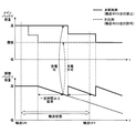
次に、図3〜図6を参照して、本実施例の走行制御装置10の動作について説明する。図3は、本実施例の走行制御装置10においてECU−Aが実行するメインルーチンの一例のフローチャートを示す。図4は、本実施例の走行制御装置10においてECU−Aが実行するサブルーチンの一例のフローチャートを示す。図5は、本実施例の走行制御装置10においてECU−Aが他のECU−B,ECU−C,ECU−D,ECU−Eから送信されるメッセージの受信有無に応じて車両状態を判定するためのマトリクスを表した図を示す。また、図6は、本実施例の走行制御装置10による効果を説明するための図を示す。
Next, with reference to FIGS. 3-6, operation | movement of the traveling
本実施例において、ハイブリッド車両は、電気モータを駆動源として用いたEV走行と、エンジンを駆動源として用いたエンジン走行と、で選択的に駆動制御される。具体的には、一般的に、高圧バッテリ12の残存容量が所定閾値以上である場合は、EV走行が許可される。そして、かかるEV走行許可状態において、アクセル開度や車速などの所定条件が満たされないときは自車両はEV走行しないが、その所定条件が満たされたときに自車両がEV走行する。一方、高圧バッテリ12の残存容量が所定閾値以上である一方で上記の所定条件が満たされない場合、及び、高圧バッテリ12の残存容量が所定閾値未満である場合は、EV走行が禁止されて、自車両がエンジン走行する。また、高圧バッテリ12の残存容量が低下すると、自車両がエンジン走行することで発電して、その高圧バッテリ12が充電される。
In this embodiment, the hybrid vehicle is selectively driven and controlled by EV travel using an electric motor as a drive source and engine travel using an engine as a drive source. Specifically, generally, when the remaining capacity of the high-
更に、高圧バッテリ12は、上記の所定閾値以上の残存容量(好ましくは、満充電状態)に充電されてからハイブリッド車両に組み付けられる。また、第2の電源供給ライン36を導通/遮断するヒューズ42は、作業者により、車両の組立完了後にその第2の電源供給ライン36上から取り外され、また、車両の輸送完了後、販売時にその第2の電源供給ライン36上に取り付けられる。
Furthermore, the high-
本実施例において、ハイブリッド車両が組み立てられると、以後、ECU−Aは、所定時間ごとに、自ハイブリッド車両が組み立てられてから販売されるまでの車両輸送状態にあるか否かを判別する(ステップ100)。尚、車両輸送状態は、例えば、車両の組み立てが完了してから車両組立工場→国内ヤード→船→海外ヤード→ディーラ販売店を経由して販売されるまでの期間中で肯定されるものであってもよく、また、作業者が車両を走行移動させるときを含む期間中で肯定されるものとしてもよい。また、車両輸送状態は、その期間中の一部だけで肯定されるものとしてもよいが、その期間中すべてで肯定されかつその期間以外では否定されるものとするのが好ましい。 In this embodiment, when the hybrid vehicle is assembled, the ECU-A thereafter determines whether the vehicle is in a vehicle transport state from when the hybrid vehicle is assembled until it is sold every predetermined time (step). 100). The vehicle transport status is affirmed during the period from when the vehicle assembly is completed until it is sold via the vehicle assembly factory → domestic yard → ship → oversea yard → dealer dealer. In addition, it may be affirmed during a period including when the worker moves and moves the vehicle. In addition, the vehicle transportation state may be affirmed only in a part during the period, but it is preferable that the vehicle transportation state is affirmed in the whole period and denied in other periods.
ECU−Aは、上記の如くステップ100にて自ハイブリッド車両が車両輸送状態にあるか否かを判別するうえで、図4に示すルーチンを実行する。具体的には、まず、ECU−Aは、車内LAN44を介して通信接続する他のすべてのECU−B,ECU−C,ECU−D,ECU−Eからメッセージb,c,d,eを受信できているか否かを判別する(ステップ200)。尚、これらの各メッセージb,c,d,eは、各ECU−B,ECU−C,ECU−D,ECU−Eが車内LAN44を通じてECU−Aへ送信するものであればよく、定期的に送信すべき各種のデータなどであってもよい。
The ECU-A executes the routine shown in FIG. 4 when determining whether or not the own hybrid vehicle is in the vehicle transport state in
その結果、ECU−Aは、上記ステップ200にてすべてのECU−B,ECU−C,ECU−D,ECU−Eからのメッセージb,c,d,eを受信できていると判別した場合は、ヒューズ42が第2の電源供給ライン36上に取り付けられていると判断し、自ハイブリッド車両が車両輸送状態以外の状態(具体的には、正常状態)にあると判定する(ステップ202)。この場合、ECU−Aは、上記ステップ100にて自ハイブリッド車両が車両輸送状態にないと判定する。
As a result, when the ECU-A determines in
一方、ECU−Aは、上記ステップ200にてすべてのECU−B,ECU−C,ECU−D,ECU−Eのうち少なくとも何れか一のECUからのメッセージb,c,d,eを受信できていないと判別した場合は、次に、第2の電源供給ライン36上のヒューズ42の配下に位置するすべてのECU(具体的には、第2の電源供給ライン36に接続するECU−D及びECU−E)からメッセージd,eを受信できていないか否かを判別する(ステップ204)。
On the other hand, ECU-A can receive messages b, c, d, e from at least one of all ECU-B, ECU-C, ECU-D, ECU-E in
その結果、ECU−Aは、上記ステップ204にて第2の電源供給ライン36上のヒューズ42の配下に位置するすべてのECUのうち少なくとも何れか一のECUからのメッセージd,eを受信できていると判別した場合は、ヒューズ42が第2の電源供給ライン36上に取り付けられていると判断し、自ハイブリッド車両が車両輸送状態以外の状態(例えば、メッセージdが受信されている一方でメッセージeが受信されていないときは、その未受信メッセージeを送信したECU−Eの故障異常など)にあると判定する(ステップ206)。この場合、ECU−Aは、上記ステップ100にて自ハイブリッド車両が車両輸送状態にないと判定する。
As a result, the ECU-A can receive the messages d and e from at least one of all the ECUs located under the
一方、ECU−Aは、上記ステップ204にて第2の電源供給ライン36上のヒューズ42の配下に位置するすべてのECUからのメッセージd,eを受信できていないと判別した場合は、次に、第2の電源供給ライン36上のヒューズ42の配下に位置するECU以外のECU(具体的には、ECU−Aを除く第1の電源供給ライン30上に位置するECU−B及びECU−C)からメッセージb,cを受信できているか否かを判別する(ステップ208)。
On the other hand, if the ECU-A determines in
その結果、ECU−Aは、上記ステップ208にて第1の電源供給ライン30上に位置するECUからのメッセージb,cを受信できていないと判別した場合は、車内LAN44を介して通信接続する他のすべてのECU−B,ECU−C,ECU−D,ECU−Eからのメッセージb,c,d,eを受信できていないとして、他のECUとの間で通信異常が生じていると判定する(ステップ210)。この場合、ECU−Aは、上記ステップ100にて自ハイブリッド車両が車両輸送状態にないと判定する。
As a result, if the ECU-A determines in
一方、ECU−Aは、上記ステップ208にて第1の電源供給ライン30上に位置するECUからのメッセージb,cを受信できていると判別した場合は、第1の電源供給ライン30上に位置するECUからのメッセージb,cを受信できている一方で、第2の電源供給ライン36上に位置するすべてのECUからのメッセージd,eを受信できていないので、ヒューズ42が第2の電源供給ライン36上から取り外されていると判断し、自ハイブリッド車両が車両輸送状態にあると判定する(ステップ212)。この場合、ECU−Aは、上記ステップ100にて自ハイブリッド車両が車両輸送状態にあると判定する。
On the other hand, if the ECU-A determines in
ECU−Aは、上記ステップ212にて自ハイブリッド車両が車両輸送状態にあると判定すると、以後、第2の電源供給ライン36上のヒューズ42の配下に位置するECU(具体的には、第2の電源供給ライン36に接続するECU−D及びECU−E)からメッセージd,eを受信できるか否かを判別する(ステップ214)。
If the ECU-A determines in
その結果、ECU−D及びECU−Eからのメッセージd,eを受信できないと判別した場合は、今回処理時にも自ハイブリッド車両が車両輸送状態にあると判定する。一方、ECU−D及びECU−Eからのメッセージd,eを受信できたと判別した場合は、前回処理時から今回処理時にかけてヒューズ42が第2の電源供給ライン36上に取り付けられたと判断し、自ハイブリッド車両が車両輸送状態になくなったと判定する(ステップ216)。この場合、ECU−Aは、上記ステップ100にて自ハイブリッド車両が車両輸送状態にないと判定する。
As a result, when it is determined that the messages d and e from the ECU-D and ECU-E cannot be received, it is determined that the own hybrid vehicle is still in the vehicle transport state even during the current process. On the other hand, if it is determined that the messages d and e from the ECU-D and ECU-E have been received, it is determined that the
ECU−Aは、上記ステップ100にて自ハイブリッド車両が車両輸送状態にあると判定した場合は、次に、その車両輸送中において、高圧バッテリ12を用いたEV走行を禁止すると共に、低圧バッテリ14を充電するときの充電電圧を、自ハイブリッド車両が車両輸送状態にない場合の充電電圧(通常の充電電圧)よりも高くする(ステップ110)。一方、自ハイブリッド車両が車両輸送状態にないと判定した場合は、上記ステップ100をジャンプして、次のステップを実行する。
If the ECU-A determines in
ECU−Aは、上記ステップ100又は110の処理を実行すると、次に、補機用の低圧バッテリ14の充電が前回完了してから自ハイブリッド車両の駐車が継続する駐車時間が予め定められた所定時間だけ経過するか否かを判別する(ステップ120)。尚、この所定時間は、低圧バッテリ14が充電されることなく車両の駐車が継続した際にその低圧バッテリ14に過放電によるバッテリ劣化が生ずると判断される最短の時間であって、例えば、一週間や二週間,1ヶ月などに設定されている。この判別は、肯定判定がなされるまで繰り返し実行される。
When the ECU-A executes the process of
そして、ECU−Aは、自ハイブリッド車両の駐車時間が所定時間経過したと判定すると、次に、高圧バッテリ12の残存容量が所定閾値以上であるか否かを判別する(ステップ130)。尚、この所定閾値は、上記したEV走行とエンジン走行とを選択するうえでの境界値となる高圧バッテリ12の残存容量と同じ値であってもよいが、異なる値であってもよい。
If the ECU-A determines that the parking time of the hybrid vehicle has elapsed a predetermined time, it next determines whether or not the remaining capacity of the high-
その結果、ECU−Aは、高圧バッテリ12の残存容量が所定閾値以上であると判別した場合は、そのメインの高圧バッテリ12からDC−DCコンバータ16を介して補機用の低圧バッテリ14へ電力供給を行うことでその低圧バッテリ14の充電を実施する(ステップ140)。一方、ECU−Aは、高圧バッテリ12の残存容量が所定閾値未満であると判別した場合は、その高圧バッテリ12からDC−DCコンバータ16を介した補機用の低圧バッテリ14への電力供給を行わず、低圧バッテリ14の充電を行わない。
As a result, when the ECU-A determines that the remaining capacity of the high-
このように、本実施例の走行制御装置10においては、自ハイブリッド車両が車両輸送状態にない場合は、高圧バッテリ12からの電力供給により駆動する電気モータ20を用いたEV走行を許可する一方、自ハイブリッド車両が車両輸送状態にある場合は、そのEV走行を禁止することができる。
Thus, in the
EV走行が許可されていると、そのEV走行が実施された際に高圧バッテリ12から電気モータ20へ電力が供給されるので、高圧バッテリ12から多くの電力が持ち出されることとなる(図6において破線で示す対比例のものを参照)。一方、EV走行が禁止されていると、EV走行の実施に伴う高圧バッテリ12から電気モータ20への電力供給は中止されるので、高圧バッテリ12からの電力の持ち出しが制限される(図6において実線で示す本実施例のものを参照)。
If EV traveling is permitted, electric power is supplied from the
従って、本実施例の走行制御装置10によれば、対比例のものと異なり、ハイブリッド車両の輸送時にEV走行を禁止することで、その輸送中に高圧バッテリ12の残存容量が低下し易くなるのを防止し、その容量低下を抑えることができる。この点、自ハイブリッド車両が販売店に納入され或いは購入者に納車される際などにメインの高圧バッテリ12の残存容量を比較的高い状態に維持させることができるので、車両輸送中においてその高圧バッテリ12からの電力供給によって補機用の低圧バッテリ14を充電できる機会を増やすことができ、その低圧バッテリ14のバッテリ上がりを確実に防止して過放電に伴う劣化を確実に防止することができる。
Therefore, according to the traveling
尚、本実施例の走行制御装置10においては、自ハイブリッド車両の駐車時間が所定時間経過する毎に、メインの高圧バッテリ12からDC−DCコンバータ16を介して補機用の低圧バッテリ14へ電力供給を行うことで、その低圧バッテリ14を充電させることができる。このため、本実施例によれば、自ハイブリッド車両が長期間に亘って放置される場合にも、補機用の低圧バッテリ14がバッテリ上がりを起こすのを防止することができる。
In the
また、本実施例においては、自ハイブリッド車両が車両輸送状態にある場合は、低圧バッテリ14を充電する際の充電電圧(すなわち、DC−DCコンバータ16の出力する出力電圧)が、車両輸送状態にない場合に比して高くされる。 In the present embodiment, when the own hybrid vehicle is in the vehicle transportation state, the charging voltage when charging the low voltage battery 14 (that is, the output voltage output from the DC-DC converter 16) is in the vehicle transportation state. Increased compared to when not.
一般的に、車両輸送中は、駐車時間が比較的長く、短い距離だけ走行するショートトリップが多いため、低圧バッテリ14の容量が低下し易く、回復し難い。これに対して、低圧バッテリ14への充電電圧が高いと、高圧バッテリ12からDC−DCコンバータ16を介した低圧バッテリ14への充電効率が向上する。従って、本実施例の走行制御装置10によれば、車両輸送中は、車両輸送中でないときに比べて、高圧バッテリ12からDC−DCコンバータ16を介した低圧バッテリ14への充電効率を向上させることができるので、この点でも、低圧バッテリ14のバッテリ上がりを抑制することができる。
In general, during vehicle transportation, since the parking time is relatively long and there are many short trips that travel only a short distance, the capacity of the low-
更に、本実施例の走行制御装置10においては、自ハイブリッド車両が車両輸送状態にあるか否かの判定を、車内LAN44を介して互いに通信接続された複数のECUのうち、(1)第2の電源供給ライン36上のヒューズ42配下に位置する何れのECU(具体的には、ECU−D及びECU−E)からのメッセージd,eもECU−Aに受信されないか否か、及び、(2)第2の電源供給ライン36上のヒューズ42配下に位置するECU以外のECU(具体的には、ECU−Aを除く第1の電源供給ライン30上に位置するECU−B及びECU−C)からのメッセージb,cがECU−Aに受信されるか否かに基づいて、行うことができる。
Further, in the
そして、上記(1)の条件及び上記(2)の条件が何れも成立する場合、すなわち、ECU−D及びECU−Eからのメッセージd,eが何れもECU−Aに受信されず、かつ、ECU−B及びECU−Cからのメッセージb,cがECU−Aに受信される場合は、自ハイブリッド車両が車両輸送状態にあると判定することができる。一方、上記(1)の条件及び上記(2)の条件のうち少なくとも一つの条件が成立しない場合は、自ハイブリッド車両が車両輸送状態にない(例えば、正常状態や通信異常状態にあるなど)と判定することができる。 When both the condition (1) and the condition (2) are satisfied, that is, neither the messages d and e from the ECU-D and the ECU-E are received by the ECU-A, and When the messages b and c from the ECU-B and ECU-C are received by the ECU-A, it can be determined that the own hybrid vehicle is in a vehicle transport state. On the other hand, if at least one of the conditions (1) and (2) is not satisfied, the hybrid vehicle is not in a vehicle transport state (for example, in a normal state or a communication abnormal state). Can be determined.
ヒューズ42は、上記の如く、車両輸送中は第2の電源供給ライン36上から取り外され、車両輸送以外は第2の電源供給ライン36上に取り付けられる輸送時ヒューズである。このため、上記の手法によれば、自ハイブリッド車両が車両輸送状態にあるか否かの判定を正確に行うことが可能である。
As described above, the
また、本実施例においては、自ハイブリッド車両が車両輸送状態にあると判定するためには、第2の電源供給ライン36上のヒューズ42配下に位置する複数のECU−D及びECU−Eからのメッセージd,eが何れもECU−Aに受信されないこと、及び、第1の電源供給ライン30上の複数のECU−B及びECU−Cからのメッセージb,cがECU−Aに受信されることが必要である。
Further, in the present embodiment, in order to determine that the own hybrid vehicle is in a vehicle transportation state, from a plurality of ECU-D and ECU-E located under the
すなわち、本実施例においては、自ハイブリッド車両が車両輸送状態にあるか否かの判定を、第2の電源供給ライン36上のヒューズ42配下に位置する唯一つのECUからのメッセージ受信の可否に基づいて行うものではなく、また、第1の電源供給ライン30上の唯一つのECUからのメッセージ受信の可否に基づいて行うものではない。このため、本実施例によれば、自ハイブリッド車両が車両輸送状態にあることと、車内LAN44を介してECU−Aへ向けてメッセージを送信する他のECU自体の故障による通信異常との識別精度を向上させることができ、自ハイブリッド車両が車両輸送状態にあるか否かの判定精度を向上させることができる。
That is, in this embodiment, whether or not the own hybrid vehicle is in a vehicle transport state is determined based on whether or not a message can be received from only one ECU located under the
更に、本実施例の如く、自ハイブリッド車両が車両輸送状態にあるか否かの判定を、車内LAN44を介して互いに通信接続される複数のECU間のメッセージ受信の有無に基づいて行う構成によれば、その判定を既存の構成を用いて行うことができるので、その判定を行うための専用のハード構成を追加(例えば、電源監視ラインの追加など)する必要はなく、ハード構成の変更は不要である。このため、本実施例によれば、自ハイブリッド車両が車両輸送状態にあるか否かの判定を、ハード構成変更に伴うコストアップを招来させることなく簡易かつ正確に行うことができる。
Further, as in the present embodiment, whether or not the hybrid vehicle is in a vehicle transport state is determined based on whether or not a message is received between a plurality of ECUs that are connected to each other via the in-
尚、上記の実施例においては、ECU−Aが図3に示すルーチン中ステップ100の処理を実行すること及び図4に示すルーチンを実行することにより特許請求の範囲に記載した「輸送状態判定手段」が、ECU−Aがステップ110において自ハイブリッド車両のEV走行を禁止することにより特許請求の範囲に記載した「バッテリ走行抑制手段」が、ECU−Aがステップ120〜140の処理を実行することにより特許請求の範囲に記載した「低圧バッテリ充電制御手段」が、ECU−Aがステップ110において車両輸送中に低圧バッテリ14を充電するときの充電電圧を通常の充電電圧よりも高くすることにより特許請求の範囲に記載した「充電電圧制御手段」が、それぞれ実現されている。また、DC−DCコンバータ16が特許請求の範囲に記載した「電圧変換器」に相当している。
In the above embodiment, the ECU-A executes the process of
ところで、上記の実施例においては、(1)第2の電源供給ライン36上のヒューズ42配下に位置するECU−D及びECU−Eからのメッセージd,eが何れもECU−Aに受信されず、かつ、(2)第2の電源供給ライン36上のヒューズ42配下に位置するECU以外の、ECU−Aを除く第1の電源供給ライン30上に位置するECU−B及びECU−Cからのメッセージb,cがECU−Aに受信される場合に、自ハイブリッド車両が車両輸送状態にあると判定するが、本発明はこれに限定されるものではなく、少なくとも上記(1)の条件が成立する場合に、自ハイブリッド車両が車両輸送状態にあると判定することとしてもよい。
By the way, in the above embodiment, (1) neither of the messages d and e from the ECU-D and ECU-E located under the
また、上記の実施例においては、自ハイブリッド車両が車両輸送状態にある場合に、高圧バッテリ12を用いたEV走行が禁止されると共に、低圧バッテリ14の充電時の充電電圧が通常の充電電圧よりも高くされるが、本発明はこれに限定されるものではなく、自ハイブリッド車両が車両輸送状態にある場合に、少なくとも高圧バッテリ12を用いたEV走行が禁止されることとすればよい。
Further, in the above embodiment, when the hybrid vehicle is in a vehicle transport state, EV traveling using the
また、上記の実施例においては、自ハイブリッド車両が車両輸送状態にある場合に、高圧バッテリ12を用いたEV走行を禁止することとしているが、本発明はこれに限定されるものではなく、自ハイブリッド車両が車両輸送状態にある場合に車両輸送状態にない場合に比してEV走行を抑制することとすればよい。
Further, in the above embodiment, EV travel using the
例えば、EV走行は、一般的に、高圧バッテリ12の残存容量が所定閾値以上である場合に許可され、一方、高圧バッテリ12の残存容量が所定閾値未満である場合に禁止されるが、このEV走行を許可/禁止するうえで用いる所定閾値を、自ハイブリッド車両が車両輸送状態にあるか否かに応じて変更することとしてもよい。すなわち、この所定閾値を、自ハイブリッド車両が車両輸送状態にある場合は車両輸送状態にない場合に比して、EV走行が許可され難い側に変更することとしてもよい。
For example, EV traveling is generally permitted when the remaining capacity of the high-
かかる変形例の構成においても、自ハイブリッド車両が車両輸送状態にある場合に、車両輸送状態にない場合に比して、EV走行が抑制され、高圧バッテリ12からの電力の持ち出しが制限されるので、ハイブリッド車両の輸送中に高圧バッテリ12の残存容量が低下し易くなるのを防止することが可能となる。
Even in the configuration of this modified example, when the own hybrid vehicle is in the vehicle transport state, EV traveling is suppressed and the taking out of electric power from the
また、上記の実施例は、ハイブリッド車両に適用されるものであるが、車両が車両輸送状態にあるか否かの判定手法や、車両輸送時は車両輸送以外のときに比べて低圧バッテリ14を充電する際の充電電圧を高くすることについては、ハイブリッド車両以外のエンジン車両などに適用することが可能である。
Moreover, although the above embodiment is applied to a hybrid vehicle, the low-
例えば、車両の輸送時に電源供給ライン上から取り外され、前記輸送が完了した後に前記電源供給ライン上に取り付けられるヒューズと、前記電源供給ライン上の前記ヒューズの配下に存在するすべての電子制御ユニットからのメッセージが受信されず、かつ、前記ヒューズの配下に存在しない電子制御ユニットからのメッセージが受信される場合に、車両が輸送状態にあると判定する輸送状態判定手段と、を備える車両輸送状態判定装置は、車両が車両輸送状態にあるか否かを正確に判定することができる。かかる車両輸送状態判定装置によれば、車両輸送状態の判定を行うための専用のハード構成を追加(例えば、電源監視ラインの追加など)する必要はなく、ハード構成の変更は不要であるので、自ハイブリッド車両が車両輸送状態にあるか否かの判定を、ハード構成変更に伴うコストアップを招来させることなく簡易かつ正確に行うことが可能である。 For example, from a fuse that is removed from the power supply line during transportation of the vehicle and attached to the power supply line after the transportation is completed, and all electronic control units existing under the fuse on the power supply line A vehicle transportation state determination comprising: a transportation state determination unit that determines that the vehicle is in a transportation state when a message from the electronic control unit that does not exist under the fuse is received. The device can accurately determine whether the vehicle is in a vehicle transport state. According to such a vehicle transportation state determination device, it is not necessary to add a dedicated hardware configuration for determining the vehicle transportation state (for example, addition of a power supply monitoring line), and it is not necessary to change the hardware configuration. It is possible to easily and accurately determine whether or not the own hybrid vehicle is in a vehicle transportation state without causing an increase in cost associated with a hardware configuration change.
また、車両に搭載される補機バッテリの充電を制御する装置であって、前記車両が輸送状態にあることを判定する輸送状態判定手段と、前記輸送状態判定手段により前記車両が輸送状態にあることが判定される場合は、前記車両が輸送状態にあることが判定されない場合に比して、前記補機バッテリを充電する際の充電電圧を高くする充電電圧制御手段と、を備える車両用充電制御装置は、車両輸送中は車両輸送中でないときに比べて、低圧バッテリの充電効率を向上させることができる。かかる車両用充電制御装置によれば、車両輸送中に低圧バッテリのバッテリ上がりを抑制することが可能である。 Moreover, it is an apparatus for controlling charging of an auxiliary battery mounted on a vehicle, and the vehicle is in a transportation state by the transportation state judgment means for judging that the vehicle is in a transportation state and the transportation state judgment means. A charging voltage control means for increasing a charging voltage when charging the auxiliary battery as compared with a case where it is not determined that the vehicle is in a transportation state. The control device can improve the charging efficiency of the low voltage battery during vehicle transportation compared to when the vehicle is not in transportation. According to such a charging control device for a vehicle, it is possible to suppress battery low of the low voltage battery during vehicle transportation.
10 走行制御装置
12 高圧バッテリ
14 低圧バッテリ
16 DC−DCコンバータ
18 ECU−A
30 第1の電源供給ライン
32,34,38,40 ECU−B,ECU−C,ECU−D,ECU−E
36 第2の電源供給ライン
42 ヒューズ
44 車内LAN
DESCRIPTION OF
30 1st
36 Second
Claims (9)
前記ハイブリッド車両が輸送状態にあることを判定する輸送状態判定手段と、
前記輸送状態判定手段により前記ハイブリッド車両が輸送状態にあることが判定される場合に、前記ハイブリッド車両が輸送状態にあることが判定されない場合に比して、前記第1の走行の選択/非選択に用いる閾値を、該第1の走行が選択され難い側に変更するバッテリ走行抑制手段と、
を備えることを特徴とするハイブリッド車両の走行制御装置。 A first travel using a motor having a high-voltage battery and a low-voltage battery as a drive source, and a second travel using an engine as a drive source. A travel control device mounted on a hybrid vehicle to be driven,
Transportation state determination means for determining that the hybrid vehicle is in a transportation state;
Selection / non-selection of the first travel when the transport state determination means determines that the hybrid vehicle is in a transport state compared to a case where it is not determined that the hybrid vehicle is in a transport state Battery travel suppression means for changing the threshold used for the first travel to a side on which the first travel is difficult to be selected ;
A travel control device for a hybrid vehicle, comprising:
前記ハイブリッド車両が輸送状態にあることを判定する輸送状態判定手段と、
前記輸送状態判定手段により前記ハイブリッド車両が輸送状態にあることが判定される場合に、前記第1の走行を抑制するバッテリ走行抑制手段と、
前記輸送状態判定手段により前記ハイブリッド車両が輸送状態にあることが判定される場合は、前記ハイブリッド車両が輸送状態にあることが判定されない場合に比して、前記低圧バッテリを充電する際の充電電圧を高くする充電電圧制御手段と、
を備えることを特徴とするハイブリッド車両の走行制御装置。 A first travel using a motor having a high-voltage battery and a low-voltage battery as a drive source, and a second travel using an engine as a drive source. A travel control device mounted on a hybrid vehicle to be driven,
Transportation state determination means for determining that the hybrid vehicle is in a transportation state;
Battery travel suppression means that suppresses the first travel when the transport state determination means determines that the hybrid vehicle is in a transport state;
When it is determined by the transportation state determination means that the hybrid vehicle is in a transportation state, a charging voltage for charging the low-voltage battery as compared with a case where it is not determined that the hybrid vehicle is in a transportation state Charging voltage control means for increasing
A travel control device for a hybrid vehicle, comprising:
前記充電電圧制御手段は、前記輸送状態判定手段により前記ハイブリッド車両が輸送状態にあることが判定される場合は、前記ハイブリッド車両が輸送状態にあることが判定されない場合に比して、前記充電電圧としての前記電圧変換器による前記低圧バッテリへの出力電圧を高くすることを特徴とする請求項2乃至4の何れか一項記載のハイブリッド車両の走行制御装置。 A voltage converter that performs voltage conversion between the high-voltage battery and the low-voltage battery;
The charging voltage control means is configured such that when the transportation state determination means determines that the hybrid vehicle is in a transportation state, the charging voltage control means compares the charging voltage with a case where it is not determined that the hybrid vehicle is in a transportation state. The travel control apparatus for a hybrid vehicle according to any one of claims 2 to 4, wherein an output voltage to the low-voltage battery by the voltage converter is increased.
前記輸送状態判定手段は、前記電源供給ライン上の前記ヒューズの配下に存在するすべての電子制御ユニットからのメッセージが受信されない場合に、前記ハイブリッド車両が輸送状態にあると判定することを特徴とする請求項1乃至7の何れか一項記載のハイブリッド車両の走行制御装置。 The detached from the power supply on the line when the hybrid vehicle transport, including a fuse attached to the power supply line after the transport has been completed,
The transportation state determination means determines that the hybrid vehicle is in a transportation state when messages from all electronic control units existing under the fuse on the power supply line are not received. The travel control apparatus for a hybrid vehicle according to any one of claims 1 to 7.
Priority Applications (5)
| Application Number | Priority Date | Filing Date | Title |
|---|---|---|---|
| JP2013027156A JP5966962B2 (en) | 2013-02-14 | 2013-02-14 | Hybrid vehicle travel control device |
| CN201480007969.XA CN104981960B (en) | 2013-02-14 | 2014-02-06 | Hybrid car travel control device |
| PCT/IB2014/000110 WO2014125349A2 (en) | 2013-02-14 | 2014-02-06 | Hybrid vehicle running control apparatus |
| US14/767,453 US9517765B2 (en) | 2013-02-14 | 2014-02-06 | Hybrid vehicle running control apparatus |
| EP14706328.3A EP2957016B1 (en) | 2013-02-14 | 2014-02-06 | Hybrid vehicle running control apparatus |
Applications Claiming Priority (1)
| Application Number | Priority Date | Filing Date | Title |
|---|---|---|---|
| JP2013027156A JP5966962B2 (en) | 2013-02-14 | 2013-02-14 | Hybrid vehicle travel control device |
Publications (2)
| Publication Number | Publication Date |
|---|---|
| JP2014156170A JP2014156170A (en) | 2014-08-28 |
| JP5966962B2 true JP5966962B2 (en) | 2016-08-10 |
Family
ID=50159304
Family Applications (1)
| Application Number | Title | Priority Date | Filing Date |
|---|---|---|---|
| JP2013027156A Active JP5966962B2 (en) | 2013-02-14 | 2013-02-14 | Hybrid vehicle travel control device |
Country Status (5)
| Country | Link |
|---|---|
| US (1) | US9517765B2 (en) |
| EP (1) | EP2957016B1 (en) |
| JP (1) | JP5966962B2 (en) |
| CN (1) | CN104981960B (en) |
| WO (1) | WO2014125349A2 (en) |
Families Citing this family (13)
| Publication number | Priority date | Publication date | Assignee | Title |
|---|---|---|---|---|
| JP5821899B2 (en) | 2013-06-04 | 2015-11-24 | トヨタ自動車株式会社 | Battery deterioration detection device |
| KR101704266B1 (en) * | 2015-10-02 | 2017-02-07 | 현대자동차주식회사 | Method for controlling battery soc of hybrid vehicle |
| CN105313718B (en) * | 2015-11-25 | 2018-07-03 | 北京新能源汽车股份有限公司 | Vehicular accumulator cell charging equipment, system and method |
| JP6593129B2 (en) * | 2015-11-26 | 2019-10-23 | いすゞ自動車株式会社 | Hybrid vehicle and control method thereof |
| KR101918341B1 (en) * | 2015-12-07 | 2018-11-13 | 현대자동차주식회사 | Control method of low dc-dc conveter for hybrid vehicle |
| JP6373329B2 (en) * | 2016-02-19 | 2018-08-15 | 本田技研工業株式会社 | Vehicle control device |
| US10427680B2 (en) | 2016-02-19 | 2019-10-01 | Honda Motor Co., Ltd. | Control system for vehicle, and control method for vehicle |
| KR101876027B1 (en) * | 2016-06-03 | 2018-07-06 | 현대자동차주식회사 | Apparatus for controlling ldc in green car and method thereof |
| US10401937B2 (en) * | 2017-02-14 | 2019-09-03 | GM Global Technology Operations LLC | Method and apparatus for detection of battery drain |
| JP7147621B2 (en) * | 2019-02-20 | 2022-10-05 | トヨタ自動車株式会社 | Charging control device and method |
| CN110303905B (en) * | 2019-06-24 | 2023-05-05 | 中国第一汽车股份有限公司 | High-voltage topological structure for pure electric commercial vehicle and power-on and power-off control method |
| JP7244392B2 (en) * | 2019-09-04 | 2023-03-22 | トヨタ自動車株式会社 | vehicle controller |
| TWI779451B (en) * | 2021-01-05 | 2022-10-01 | 光陽工業股份有限公司 | Power management system for electric locomotive |
Family Cites Families (24)
| Publication number | Priority date | Publication date | Assignee | Title |
|---|---|---|---|---|
| JP2634524B2 (en) * | 1991-12-06 | 1997-07-30 | 矢崎総業株式会社 | Intermittent mechanism of dark current fuse |
| JP3316791B2 (en) | 1996-08-28 | 2002-08-19 | 矢崎総業株式会社 | Vehicle battery power supply |
| JP4239435B2 (en) | 2001-06-04 | 2009-03-18 | トヨタ自動車株式会社 | Battery capacity determination method and battery capacity determination device |
| JP2005333690A (en) * | 2004-05-18 | 2005-12-02 | Denso Corp | Controller of hybrid vehicle |
| JP4218634B2 (en) * | 2004-12-16 | 2009-02-04 | 株式会社デンソー | Charge control device for hybrid type vehicle |
| JP2007060791A (en) * | 2005-08-24 | 2007-03-08 | Toyota Motor Corp | Power supply device for vehicle |
| US7966105B2 (en) * | 2006-04-11 | 2011-06-21 | Asset Intelligence, Llc | Method and apparatus for power management of asset tracking system |
| JP2008126812A (en) | 2006-11-20 | 2008-06-05 | Toyota Motor Corp | Vehicle height adjusting device |
| JP2008290604A (en) * | 2007-05-25 | 2008-12-04 | Auto Network Gijutsu Kenkyusho:Kk | Electric power source control system for vehicle |
| JP2009029233A (en) * | 2007-07-26 | 2009-02-12 | Omron Corp | Entry system for vehicle |
| JP2009083789A (en) * | 2007-10-02 | 2009-04-23 | Toyota Motor Corp | Vehicular power source control device, transmission device, and power source control communication system |
| WO2009094367A1 (en) | 2008-01-22 | 2009-07-30 | Honda Motor Co., Ltd. | Systems and methods to control electrical systems of vehicles |
| BRPI1014989A2 (en) * | 2009-04-27 | 2017-03-28 | Volvo Lastvagnar Ab | a battery charging system for a hybrid electric vehicle |
| WO2010131340A1 (en) | 2009-05-13 | 2010-11-18 | トヨタ自動車株式会社 | Vehicle power conversion device and vehicle in which same is installed |
| WO2010137100A1 (en) * | 2009-05-25 | 2010-12-02 | トヨタ自動車株式会社 | Hybrid automobile and method for controlling same |
| US9187083B2 (en) * | 2009-09-16 | 2015-11-17 | Polaris Industries Inc. | System and method for charging an on-board battery of an electric vehicle |
| JP5160523B2 (en) | 2009-11-04 | 2013-03-13 | 本田技研工業株式会社 | Electric car |
| JP2011189788A (en) | 2010-03-12 | 2011-09-29 | Toyota Motor Corp | Device and method for diagnosing sign of failure |
| JP5515908B2 (en) * | 2010-03-18 | 2014-06-11 | 三洋電機株式会社 | Power supply device and vehicle equipped with the same |
| JP5530813B2 (en) * | 2010-06-04 | 2014-06-25 | トヨタ自動車株式会社 | Hybrid vehicle and control method thereof |
| JP5640477B2 (en) | 2010-06-08 | 2014-12-17 | マツダ株式会社 | Battery remaining capacity detection method and detection apparatus |
| JP5168330B2 (en) * | 2010-09-09 | 2013-03-21 | トヨタ自動車株式会社 | LOAD DRIVE DEVICE, VEHICLE EQUIPPED WITH THE SAME, AND METHOD FOR CONTROLLING LOAD DRIVE DEVICE |
| JP5177255B2 (en) * | 2011-05-12 | 2013-04-03 | 日産自動車株式会社 | Dark current interruption device and dark current interruption method |
| US8954215B2 (en) * | 2012-05-07 | 2015-02-10 | Ford Global Technologies, Llc | Driveline lash control method during driver tip-in/out |
-
2013
- 2013-02-14 JP JP2013027156A patent/JP5966962B2/en active Active
-
2014
- 2014-02-06 EP EP14706328.3A patent/EP2957016B1/en active Active
- 2014-02-06 CN CN201480007969.XA patent/CN104981960B/en not_active Expired - Fee Related
- 2014-02-06 WO PCT/IB2014/000110 patent/WO2014125349A2/en active Application Filing
- 2014-02-06 US US14/767,453 patent/US9517765B2/en active Active
Also Published As
| Publication number | Publication date |
|---|---|
| WO2014125349A3 (en) | 2015-07-09 |
| US20160001772A1 (en) | 2016-01-07 |
| JP2014156170A (en) | 2014-08-28 |
| EP2957016A2 (en) | 2015-12-23 |
| US9517765B2 (en) | 2016-12-13 |
| EP2957016B1 (en) | 2022-11-16 |
| CN104981960A (en) | 2015-10-14 |
| CN104981960B (en) | 2018-03-30 |
| WO2014125349A2 (en) | 2014-08-21 |
| WO2014125349A8 (en) | 2014-10-16 |
Similar Documents
| Publication | Publication Date | Title |
|---|---|---|
| JP5966962B2 (en) | Hybrid vehicle travel control device | |
| JP5644322B2 (en) | Countermeasure device for inappropriate battery replacement of electric vehicle | |
| KR101103877B1 (en) | Method for controlling variable voltage for hybrid vehicle | |
| US8768553B2 (en) | Method and system for controlling charging of battery for hybrid electric vehicle | |
| JP5010288B2 (en) | Control device for hybrid vehicle | |
| WO2015098012A1 (en) | Control system and vehicle power supply | |
| CN103909830A (en) | Fail-safe Method And Apparatus For High Voltage Parts In Hybrid Vehicle | |
| JP2014027864A (en) | Low voltage dc converter active control system of electric automobile | |
| US9346364B2 (en) | Method for emergency driving of hybrid electric vehicle | |
| JP2016510706A (en) | Operation method and arrangement of hybrid electric vehicle | |
| US20120191281A1 (en) | Electric vehicle | |
| JP6860424B2 (en) | Electric vehicle control device | |
| CN107107764B (en) | Method and device for charging an electrical energy storage system in a vehicle | |
| WO2016125852A1 (en) | Vehicle power-source device and vehicle-power-source-device control method | |
| KR100844729B1 (en) | Device and method for LDC control of HEV | |
| JP5675561B2 (en) | Electric car | |
| JP6776989B2 (en) | Travel control device | |
| JP2014039415A (en) | Charge control device | |
| JP5733198B2 (en) | Hybrid vehicle | |
| JP2011116223A (en) | Controller for hybrid electric vehicle | |
| JP2018501148A (en) | Method for managing the state of charge of a traveling battery of a hybrid vehicle | |
| JP2015085707A (en) | Electric power supply system of hybrid vehicle | |
| JP2015523257A (en) | Transient polarity control with insulated contactors | |
| CN114572012A (en) | Electrified powertrain with maximum performance mode control strategy using extended inverter limits | |
| WO2017115628A1 (en) | Power management device and failure detection method |
Legal Events
| Date | Code | Title | Description |
|---|---|---|---|
| A977 | Report on retrieval |
Free format text: JAPANESE INTERMEDIATE CODE: A971007 Effective date: 20141210 |
|
| A131 | Notification of reasons for refusal |
Free format text: JAPANESE INTERMEDIATE CODE: A131 Effective date: 20150203 |
|
| A521 | Request for written amendment filed |
Free format text: JAPANESE INTERMEDIATE CODE: A523 Effective date: 20150403 |
|
| A131 | Notification of reasons for refusal |
Free format text: JAPANESE INTERMEDIATE CODE: A131 Effective date: 20151104 |
|
| TRDD | Decision of grant or rejection written | ||
| A01 | Written decision to grant a patent or to grant a registration (utility model) |
Free format text: JAPANESE INTERMEDIATE CODE: A01 Effective date: 20160607 |
|
| A61 | First payment of annual fees (during grant procedure) |
Free format text: JAPANESE INTERMEDIATE CODE: A61 Effective date: 20160620 |
|
| R151 | Written notification of patent or utility model registration |
Ref document number: 5966962 Country of ref document: JP Free format text: JAPANESE INTERMEDIATE CODE: R151 |