EP2708421B1 - Dark current cutoff device and dark current cutoff method - Google Patents
Dark current cutoff device and dark current cutoff method Download PDFInfo
- Publication number
- EP2708421B1 EP2708421B1 EP12781782.3A EP12781782A EP2708421B1 EP 2708421 B1 EP2708421 B1 EP 2708421B1 EP 12781782 A EP12781782 A EP 12781782A EP 2708421 B1 EP2708421 B1 EP 2708421B1
- Authority
- EP
- European Patent Office
- Prior art keywords
- unit
- failure
- open
- recording
- load
- Prior art date
- Legal status (The legal status is an assumption and is not a legal conclusion. Google has not performed a legal analysis and makes no representation as to the accuracy of the status listed.)
- Active
Links
- 238000000034 method Methods 0.000 title claims description 22
- 230000005856 abnormality Effects 0.000 claims description 41
- 230000000694 effects Effects 0.000 claims description 11
- 238000004891 communication Methods 0.000 description 13
- 238000010586 diagram Methods 0.000 description 6
- 238000001514 detection method Methods 0.000 description 4
- 230000002159 abnormal effect Effects 0.000 description 2
- 238000005516 engineering process Methods 0.000 description 1
- 230000002708 enhancing effect Effects 0.000 description 1
- 238000003672 processing method Methods 0.000 description 1
Images


Classifications
-
- B—PERFORMING OPERATIONS; TRANSPORTING
- B60—VEHICLES IN GENERAL
- B60R—VEHICLES, VEHICLE FITTINGS, OR VEHICLE PARTS, NOT OTHERWISE PROVIDED FOR
- B60R16/00—Electric or fluid circuits specially adapted for vehicles and not otherwise provided for; Arrangement of elements of electric or fluid circuits specially adapted for vehicles and not otherwise provided for
- B60R16/02—Electric or fluid circuits specially adapted for vehicles and not otherwise provided for; Arrangement of elements of electric or fluid circuits specially adapted for vehicles and not otherwise provided for electric constitutive elements
- B60R16/03—Electric or fluid circuits specially adapted for vehicles and not otherwise provided for; Arrangement of elements of electric or fluid circuits specially adapted for vehicles and not otherwise provided for electric constitutive elements for supply of electrical power to vehicle subsystems or for
- B60R16/033—Electric or fluid circuits specially adapted for vehicles and not otherwise provided for; Arrangement of elements of electric or fluid circuits specially adapted for vehicles and not otherwise provided for electric constitutive elements for supply of electrical power to vehicle subsystems or for characterised by the use of electrical cells or batteries
Definitions
- the present invention relates to a dark current cutoff device and a dark current cutoff method.
- JP2006008057A discloses a wire breaking detection method for a vehicle.
- the loads there is a load that records failure information. That is to say, among the loads, there is a load that determines, as a failure, such a case where the unit concerned is not supplied with electrical power and cannot operate normally, and then records failure information indicating that effect.
- the load having a function to perform failure recording processing undesirably performs the failure recording processing since the supply of the electrical power is cut off. If the failure recording processing is undesirably performed as described above, then in a dealer or the like, an operation of deleting the failure information is required at the time of selling the vehicle. Meanwhile, if the short-circuit pin or the like is not pulled out so that the failure recording processing cannot be performed, then the dark current cannot be cut off, and a cutoff effect for the dark current is lowered.
- the present invention has been made in order to solve such conventional problems as described above. It is an object of the present invention to provide a dark current cutoff device and a dark current cutoff method, which do not require the operation of deleting the failure information, and are capable of enhancing the cutoff effect for the dark current. This objective is achieved by a dark current cutoff device and a dark current cutoff method according to the independent claims.
- a failure recording unit determines and records a case where a load does not operate as a failure of the load. Moreover, an open/close determining unit determines that an open/close unit, which is provided between a battery and the load, cuts off electrical power supply to the load at a time of being opened, and supplies electrical power to the load at a time of being closed, is opened. A recording prohibiting unit prohibits, in a case where the open/close unit is determined to be opened, the failure recording unit from determining and recording the failure.
- a failure recording unit determines and records a case where a load does not operate as a failure of the load. Moreover, an open/close determining unit determines that an open/close unit, which is provided between a battery and the load, cuts off electrical power supply to the load at a time of being opened, and supplies electrical power to the load at a time of being closed, is opened. In a case where the open/close unit is determined to be opened, a recording prohibiting unit supplies the electrical power, which is supplied from the battery, to the load by an alternative route that does not pass through the open/close unit, and prevents the case from being determined and recorded as the failure by the failure recording unit.
- FIG. 1 is a schematic configuration diagram of a dark current cutoff device 1 according to this embodiment.
- a dark current cutoff device 1 is composed of: a battery 10; loads 20; a fuse block 30; and a master unit 40.
- the battery 10 is a unit that supplies electrical power to the loads 20.
- the loads 20 are a variety of instruments such as meters, which are mounted on a vehicle.
- the loads 20 there are a large number of loads such as an audio instrument, to which it is not necessary to supply the electrical power at the time of transporting and storing the vehicle.
- the fuse block 30 is a block that includes a large number of fuses 31 which protect the loads 20 from a larger current than a rated current in the case where the larger current concerned flows through the loads 20. Such a current from the battery 10 is supplied through this fuse block 30 to the respective loads 20.
- the fuse block 30 includes a cutoff switch 32 for limiting the supply of the electrical power to a part of the loads 20.
- This cutoff switch 32 is provided between the battery 10 and the loads 20, and includes a short-circuit pin 32a.
- the short-circuit pin 32a is a pin that cuts off the supply of the electrical power to the loads 20 at the time of being pulled out (that is, at the time of being opened), and in addition, supplies the electrical power to the loads 20 at the time of being inserted (that is, at the time of being closed).
- the short-circuit pin 32a is pulled out, and the current supplied from the battery 10 is not allowed to be supplied to a part of the loads 20. In such a way, a dark current at the time of transporting and storing the vehicle is cut off.
- the dark current cutoff device 1 includes the following configuration.
- FIG. 2 is a block diagram showing main portions of the dark current cutoff device 1 according to this embodiment.
- the master unit 40 includes an open/close determining unit 41; an operation instructing unit (prohibition instructing unit) 42; and a recording prohibiting unit 43.
- the load 20 includes a failure recording unit 21 that performs the above-mentioned failure recording processing.
- the failure recording unit 21 is a unit that determines a case where the load 20 does not operate normally as a failure of the load 20, and record that effect.
- the open/close determining unit 41 is a unit that determines that the cutoff switch 32 is opened, that is, that the short-circuit pin 32a is pulled out. As shown in FIG. 1 , the master unit 40 is connected to the battery 10 through the cutoff switch 32 and a signal line 33, and the open/close determining unit 41 can determine whether the cutoff switch 32 is in an opened state or a closed state based on a voltage value inputted from the signal line 33.
- the recording prohibiting unit 43 is a unit that, in the case where it is determined by the open/close determining unit 41 that the cutoff switch 32 is opened, supplies the load 20, which performs the failure recording processing, with the electrical power, which is supplied from the battery 10, by an alternative route C that does not pass through the cutoff switch 32.
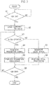
- FIG. 3 is a flowchart showing the dark current cutoff method according to this embodiment.
- the master unit 40 determines whether or not an ignition switch is turned on (S1). In the case where it is determined that the ignition switch is not turned on (S1: NO), this processing is repeated until it is determined that the ignition switch is turned on.
- the open/close determining unit 41 starts detection as to whether the cutoff switch 32 is in the opened state or the closed state (S2). Then, the open/close determining unit 41 continues to detect the state of the cutoff switch 32 until the ignition switch is turned off.
- the open/close determining unit 41 determines whether or not the cutoff switch 32 is in the opened state (S3). In the case where it is determined that the cutoff switch 32 is in the opened state (S3: YES), the operation instructing unit 42 generates a prohibition signal that instructs prohibition of the failure recording processing (S4). Then, the recording prohibiting unit 43 executes prohibition processing for prohibiting the failure recording processing (S5). That is to say, the recording prohibiting unit 43 supplies the electrical power to the load 20, which performs the failure recording processing, by the alternative route C. In such a way, even if the short-circuit pin 32a is pulled out, the electrical power is supplied to the load 20 that performs the failure recording, and the failure recording processing is not performed. Moreover, for the loads 20 which do not perform the failure recording processing, supply routes of the electrical power thereto are shut off, and accordingly, the dark current directed thereto is also cut off.
- the master unit 40 determines whether or not the ignition switch 40 is turned off (S6). In the case where the ignition switch is not turned off (S6: NO), the processing proceeds to Step S3. Meanwhile, in the case where it is determined that the ignition switch is turned off (S6: YES), the processing shown in FIG. 3 is ended.
- the operation instructing unit 42 in the case where it is determined that the cutoff switch 32 is not in the opened state (S3: NO), the operation instructing unit 42 generates a usual signal that instructs a usual operation that does not prohibit the failure recording processing (S7). Thereafter, the recording prohibiting unit 43 does not execute the prohibition processing for prohibiting the failure recording processing, but executes the usual operation (S8).
- the failure information is recorded by the failure recording unit 21, and at the time when the vehicle is repaired in the dealer or the like, the load 20 which is in the failure can be easily specified from the failure information. Thereafter, the processing proceeds to Step S6.
- the dark current cutoff device 1 and the dark current cutoff method in the case where it is determine that the cutoff switch 32 is opened, the electrical power supplied from the battery 10 is supplied to the load 10 by the alternative route C that does not pass through the cutoff switch 32, and such an operation is prevented that it is determined that there is a failure by the failure recording unit 21 and that the failure information is recorded thereby. Therefore, even if the short-circuit pin 32a is pulled out, the electrical power continues to be supplied to the load 20 that performs the failure recording processing, and the failure recording processing is not performed. Meanwhile, supply paths of the electrical power to the loads which do not perform the failure recording processing are shut off, and the dark current is cut off. Hence, in accordance with the dark current cutoff device 1 and the dark current cutoff method according to this embodiment, the operation of deleting the failure information is not required, and an effect of cutting off the dark current can be enhanced.
- the cutoff switch 32 is provided, which cuts off the supply of the electrical power to the loads 20 and supplies the electrical power to the loads 20 by pulling out and inserting the short-circuit pin 32a.
- a method of cutting off the dark current without according to this embodiment, for example, it is also conceived to classify the loads 20 in advance into the load 20 that performs the failure recording processing and the loads 20 which do not perform the failure recording processing, and to provide the cutoff switches 32 individually for the load 20 that performs the failure recording processing and the loads 20 which do not perform the failure recording processing. Then, it is conceived to pull out the short-circuit pin 32a from the fuse block 32 for the loads 20 which do not perform the failure recording processing.
- a dark current cutoff device and a dark current cutoff method according to the second embodiment are similar to those of the first embodiment; however, are partially different therefrom in configuration and processing method. A description is made below of different points from the first embodiment.
- FIG. 4 is a block diagram showing main portions of a dark current cutoff device 2 according to the second embodiment.
- the dark current cutoff device 2 shown in FIG. 4 does not supply the electrical power to the load 20, which performs the failure recording processing, at the time of opening the cutoff switch 32 as in the first embodiment, but to the load 20 that performs the failure recording processing, prohibits a function to perform the failure recording processing.
- the operation instructing unit 42 transmits, to the load 20, the prohibition signal to the effect of prohibiting the failure recording processing.
- the load 20 includes a recording prohibiting unit 22.
- the recording prohibiting unit 22 of the load 20 prohibits the failure information from being recorded by the failure recording unit 21 as a result that it is determined thereby that there is a failure. That is to say, the recording prohibiting unit 22 masks such a function of the failure recording processing by the failure recording unit 21.
- the master unit 40 includes an abnormality detecting unit 44 in place of the recording prohibiting unit 43.
- the abnormality detecting unit 44 the recording prohibiting unit 43 is a unit that detects abnormality of the cutoff switch 32. Details of this recording prohibiting unit 43 are described later.
- the recording prohibiting unit 22 does not execute the operation of prohibiting the failure recording processing. Therefore, as a result that the abnormality of the cutoff switch 32 is erroneously determined as the open of the cutoff switch 32, the failure recording processing is not prohibited in the case where the failure recording processing must be originally performed, and accordingly, the failure recording processing can be normally executed.
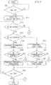
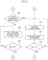
- FIG. 5 and FIG. 6 are the flowcharts showing the dark current cutoff method according to this embodiment. Note that processing of Steps S11 and S12, which are shown in FIG. 5 , is similar to that of Steps S1 and S2, which are shown in FIG. 3 , and accordingly, a description thereof is omitted.
- Step S13 the recording prohibiting unit 43 determines whether or not the abnormality occurs in the cutoff switch 32 (S13).
- the failure recording processing is prohibited (masked). Therefore, for example, if the load 20 has no failure, then at the time when the cutoff switch 32 is opened, the failure recording processing is masked, and then at the time when the cutoff switch 32 is closed, a usual determination is executed, and the failure information is not recorded.
- the failure information is recorded for only one load 20
- the usual determination is executed, and the failure information regarding the load concerned is recorded.
- the abnormality detecting unit 44 determines that the cutoff switch 32 is abnormal in the case where such a large number of the failure information is recorded.
- the open/close determining unit 41 determines whether or not the cutoff switch 32 is in the opened state (S14). In the case where it is determined that the cutoff switch 32 is in the opened state (S14: YES), the operation instructing unit 42 transmits the prohibition signal that instructs the prohibition of the failure recording processing (S15). At this time, the operation instructing unit 42 selects the load 20 having the function to perform the failure recording processing, and transmits the prohibition signal thereto.
- the master unit 40 determines whether or not there is not communication abnormality (S16). This is because, if the communication abnormality occurs, then the prohibition signal transmitted in Step S5 is not received by the load 20, and the failure recording processing is not masked. Note that, in this embodiment, upon receiving the signal from the operation instructing unit 42, the load 20 sends back a signal to the effect of the reception to the master unit 40. Hence, the master unit 40 determines that there is no communication abnormality in the case of receiving such a reply from the load 20, and determines that the communication abnormality occurs in the case of not receiving the reply from the load 20.
- the recoding prohibiting unit 22 executes the prohibition processing for prohibiting the failure recording processing (S17). In such a way, by pulling out the short-circuit pin 32a in advance, even the load 20 that performs the failure recording processing can cut off the dark current without recording the failure information at the time when the electrical power is not supplied thereto.
- the master unit 40 determines whether or not the ignition switch is turned off (S18). In the case where it is determined that the ignition switch is not turned off (S18: NO), the processing proceeds to Step S13. Meanwhile, in the case where it is determined that the ignition switch is turned off (S18: YES), then the processing shown in FIG. 5 and FIG. 6 is ended.
- the operation instructing unit 42 transmits the usual signal that instructs the usual operation that does not prohibit the failure recording processing (S19). Thereafter, the master unit 40 determines whether or not there is communication abnormality (S20). A method for determining the communication abnormality is the same as that in Step S16.
- the recording prohibiting unit 22 does not execute the prohibition processing for prohibiting the failure recording processing, but the load 20 executes the usual processing (S21).
- the failure information is recorded by the failure recording unit 21, and at the time when the vehicle is repaired in the dealer or the like, the load 20 which is in the failure can be easily specified from the failure information. Thereafter, the processing proceeds to Step S18 described above.
- Step S22 of Fig. 6 the operation instructing unit 42 transmits the usual signal that instructs the usual operation that does not prohibit the failure recording processing (S22).
- the recording prohibiting unit 22 does not execute the prohibition processing for prohibiting the failure recording processing, but the load 20 executes the usual operation (S23).
- reasons for executing the usual processing are as follows.
- the load 20 performs the failure recording processing.
- the cutoff switch 32 is abnormal, the recording of the failure information is performed for the large number of loads 20. In such a way, in the dealer or the like, from the large number of failure information, it can be determined that there occur not the individual failures of the large number of loads 20 but the abnormality of the cutoff switch 32, and exchange, repair and the like of the cutoff switch 32 can be performed.
- Step S24 the master unit 40 determines whether or not the ignition switch is turned off (S24). In the case where it is determined that the ignition switch is not turned off (S24: NO), the processing proceeds to Step S22. Meanwhile, in the case where the ignition switch is turned off (S24: YES), the processing shown in FIG. 5 and FIG. 6 is ended.
- Step S16 and Step S20 which are shown in FIG. 5 (S16, S20: NO)
- the processing proceeds to Step S25 of FIG. 6 .
- the load 20 determines whether or not the signal that indicates the state of the cutoff switch 32 is unreceived (S25). That is to say, the load 20 determines whether or not to have received the prohibition signal shown in Step S15 or the usual signal shown in Step S19 at least once in the past.
- Step S22 the processing proceeds to Step S22. Meanwhile, in the case where the signal concerned is not unreceived (S25: NO), the failure recording unit 21 holds, as a definite state, the failure information of the load 20 before the communication abnormality occurs (S26). Thereafter, the master unit 40 determines whether or not the ignition switch is turned off (S27). In the case where it is determined that the ignition switch is not turned off (S27: NO), the processing proceeds to Step S26. Meanwhile, in the case where it is determined that the ignition switch is turned off (S27: YES), the processing shown in FIG. 5 and FIG. 6 is ended.
- the dark current cutoff device 2 and the dark current cutoff method according to the second embodiment in the case where it is determine that the cutoff switch 32 is opened, this case is prohibited from being determined and recorded as a failure by the failure recording unit 21. Accordingly, even if the supply of the electrical power to the load 20 that performs the failure recording processing is cut off, the failure recording is not performed, and the operation of deleting the failure information is not required at the time of selling the vehicle. In such a way, the dark current can be cut off also for the load 20 that performs the failure recording processing, and the effect of cutting off the dark current can be enhanced.
- the recording prohibiting unit 22 does not execute the operation of prohibiting the failure recording processing. Therefore, as a result that the abnormality of the cutoff switch 32 is erroneously determined as the open of the cutoff switch 32, the failure recording processing is not prohibited in the case where the failure recording processing must be originally performed, and accordingly, the failure recording processing can be normally executed.
- the cutoff switch 32 is provided, which cuts off the supply of the electrical power to the loads 20 and supplies the electrical power to the loads 20 by pulling out and inserting the short-circuit pin 32a. Accordingly, the dark current can be appropriately cut off in a similar way to the first embodiment.
- the present invention is usable for the dark current cutoff device and method, which cut off the dark current of the vehicle on which a large number of electrical components are mounted.
Landscapes
- Engineering & Computer Science (AREA)
- Mechanical Engineering (AREA)
- Emergency Protection Circuit Devices (AREA)
- Charge And Discharge Circuits For Batteries Or The Like (AREA)
- Power Engineering (AREA)
Description
- The present invention relates to a dark current cutoff device and a dark current cutoff method.
- In recent years, electrical components have tended to be increased in a vehicle, and a dark current has tended to be increased during transportation and storage of the vehicle. Accordingly, in order to prevent a battery from running out during the transportation and storage of the vehicle, there has been proposed a technology for leaving a short-circuit pin or the like of a fuse, which is provided between loads and the battery, in a state of being pulled out (for example, refer to
Patent Literatures 1 and 2). Moreover, a device has been proposed, in which a relay is provided between the loads and the battery, and this relay is opened (for example, refer to Patent Literature 3). -
JP2006008057A -
- [PTL 1] Japanese Patent Laid-Open Publication No.
2008-126812 - [PTL 2] Japanese Patent Laid-Open Publication No.
2008-179221 - [PTL 3] Japanese Patent Laid-Open Publication No.
H10-70843 (published in 1998 - Here, among the loads, there is a load that records failure information. That is to say, among the loads, there is a load that
determines, as a failure, such a case where the unit concerned is not supplied with electrical power and cannot operate normally, and then records failure information indicating that effect. Here, in a conventional device, in such a case of pulling out the short-circuit pin or the like in order to cut off the dark current, then the load having a function to perform failure recording processing undesirably performs the failure recording processing since the supply of the electrical power is cut off. If the failure recording processing is undesirably performed as described above, then in a dealer or the like, an operation of deleting the failure information is required at the time of selling the vehicle. Meanwhile, if the short-circuit pin or the like is not pulled out so that the failure recording processing cannot be performed, then the dark current cannot be cut off, and a cutoff effect for the dark current is lowered. - The present invention has been made in order to solve such conventional problems as described above. It is an object of the present invention to provide a dark current cutoff device and a dark current cutoff method, which do not require the operation of deleting the failure information, and are capable of enhancing the cutoff effect for the dark current. This objective is achieved by a dark current cutoff device and a dark current cutoff method according to the independent claims.
- In a dark current cutoff device, a failure recording unit determines and records a case where a load does not operate as a failure of the load. Moreover, an open/close determining unit determines that an open/close unit, which is provided between a battery and the load, cuts off electrical power supply to the load at a time of being opened, and supplies electrical power to the load at a time of being closed, is opened. A recording prohibiting unit prohibits, in a case where the open/close unit is determined to be opened, the failure recording unit from determining and recording the failure.
- In another dark current cutoff device, a failure recording unit determines and records a case where a load does not operate as a failure of the load. Moreover, an open/close determining unit determines that an open/close unit, which is provided between a battery and the load, cuts off electrical power supply to the load at a time of being opened, and supplies electrical power to the load at a time of being closed, is opened. In a case where the open/close unit is determined to be opened, a recording prohibiting unit supplies the electrical power, which is supplied from the battery, to the load by an alternative route that does not pass through the open/close unit, and prevents the case from being determined and recorded as the failure by the failure recording unit.
-
-
FIG. 1 is a schematic configuration diagram of a dark current cutoff device according to a first embodiment not being part of the present invention. -
FIG. 2 is a block diagram showing main portions of the dark current cutoff device according to the first embodiment. -
FIG. 3 is a flowchart showing a dark current cutoff method according to the first embodiment. -
FIG. 4 is a block diagram showing main portions of a dark current cutoff device according to a second embodiment of the present invention. -
FIG. 5 is a first flowchart showing a dark current cutoff method according to the second embodiment. -
FIG. 6 is a second flowchart showing the dark current cut off method according to the second embodiment. - A description is made of a first embodiment based on the drawings.
FIG. 1 is a schematic configuration diagram of a darkcurrent cutoff device 1 according
to this embodiment. As shown inFIG. 1 , a darkcurrent cutoff device 1 is composed of: abattery 10;loads 20; afuse block 30; and amaster unit 40. - The
battery 10 is a unit that supplies electrical power to theloads 20. Theloads 20 are a variety of instruments such as meters, which are mounted on a vehicle. Among theloads 20, there are a large number of loads such as an audio instrument, to which it is not necessary to supply the electrical power at the time of transporting and storing the vehicle. Thefuse block 30 is a block that includes a large number offuses 31 which protect theloads 20 from a larger current than a rated current in the case where the larger current concerned flows through theloads 20. Such a current from thebattery 10 is supplied through thisfuse block 30 to therespective loads 20. - Moreover, the
fuse block 30 includes acutoff switch 32 for limiting the supply of the electrical power to a part of theloads 20. Thiscutoff switch 32 is provided between thebattery 10 and theloads 20, and includes a short-circuit pin 32a. The short-circuit pin 32a is a pin that cuts off the supply of the electrical power to theloads 20 at the time of being pulled out (that is, at the time of being opened), and in addition, supplies the electrical power to theloads 20 at the time of being inserted (that is, at the time of being closed). In general, at the time of transporting and storing the vehicle, the short-circuit pin 32a is pulled out, and the current supplied from thebattery 10 is not allowed to be supplied to a part of theloads 20. In such a way, a dark current at the time of transporting and storing the vehicle is cut off. - However, among the
loads 20, there is a load that performs failure recording processing. That is to say, among theloads 20, there is a load that determines, as a failure, such a case where the unit concerned is not supplied with the electrical power and cannot operate normally, and then records failure information indicating that effect. Therefore, if the short-circuit pin 32a is pulled out, such aload 20 performs the failure recording processing. Therefore, a dealer or the like must delete the failure information at the time of selling the vehicle. Meanwhile, if a connection relationship with thebattery 10 is maintained for theload 20 as described above at the time of transporting and storing the vehicle, then the dark current flows, resulting in lowering of a cutoff effect for the dark current. In this connection, the darkcurrent cutoff device 1 according to this embodiment includes the following configuration. -
FIG. 2 is a block diagram showing main portions of the darkcurrent cutoff device 1 according to this embodiment. As shown inFIG. 2 , themaster unit 40 includes an open/close determiningunit 41; an operation instructing unit (prohibition instructing unit) 42; and arecording prohibiting unit 43. Moreover, theload 20 includes afailure recording unit 21 that performs the above-mentioned failure recording processing. - The
failure recording unit 21 is a unit that determines a case where theload 20 does not operate normally as a failure of theload 20, and record that effect. The open/close determiningunit 41 is a unit that determines that thecutoff switch 32 is opened, that is, that the short-circuit pin 32a is pulled out. As shown inFIG. 1 , themaster unit 40 is connected to thebattery 10 through thecutoff switch 32 and asignal line 33, and the open/close determiningunit 41 can determine whether thecutoff switch 32 is in an opened state or a closed state based on a voltage value inputted from thesignal line 33. - The
recording prohibiting unit 43 is a unit that, in the case where it is determined by the open/closedetermining unit 41 that thecutoff switch 32 is opened, supplies theload 20, which performs the failure recording processing, with the electrical power, which is supplied from thebattery 10, by an alternative route C that does not pass through thecutoff switch 32. - With such a configuration, even the
load 20 that performs the failure recording processing can eliminate a necessity for an operation of deleting the failure information at the time of selling the vehicle without recording the failure information at the time when thecutoff switch 32 is opened. - Next, a description is made of a dark current cutoff method according to this embodiment with reference to ta flowchart.
FIG. 3 is a flowchart showing the dark current cutoff method according to this embodiment. - First, as shown in
FIG. 3 , themaster unit 40 determines whether or not an ignition switch is turned on (S1). In the case where it is determined that the ignition switch is not turned on (S1: NO), this processing is repeated until it is determined that the ignition switch is turned on. - Meanwhile, in the case where it is determined that the ignition switch is turned on (S1: YES), then the open/close determining
unit 41 starts detection as to whether thecutoff switch 32 is in the opened state or the closed state (S2). Then, the open/close determiningunit 41 continues to detect the state of thecutoff switch 32 until the ignition switch is turned off. - Thereafter, the open/close determining
unit 41 determines whether or not thecutoff switch 32 is in the opened state (S3). In the case where it is determined that thecutoff switch 32 is in the opened state (S3: YES), theoperation instructing unit 42 generates a prohibition signal that instructs prohibition of the failure recording processing (S4). Then, therecording prohibiting unit 43 executes prohibition processing for prohibiting the failure recording processing (S5). That is to say, therecording prohibiting unit 43 supplies the electrical power to theload 20, which performs the failure recording processing, by the alternative route C. In such a way, even if the short-circuit pin 32a is pulled out, the electrical power is supplied to theload 20 that performs the failure recording, and the failure recording processing is not performed. Moreover, for theloads 20 which do not perform the failure recording processing, supply routes of the electrical power thereto are shut off, and accordingly, the dark current directed thereto is also cut off. - Subsequently, the
master unit 40 determines whether or not theignition switch 40 is turned off (S6). In the case where the ignition switch is not turned off (S6: NO), the processing proceeds to Step S3. Meanwhile, in the case where it is determined that the ignition switch is turned off (S6: YES), the processing shown inFIG. 3 is ended. - Moreover, in the case where it is determined that the
cutoff switch 32 is not in the opened state (S3: NO), theoperation instructing unit 42 generates a usual signal that instructs a usual operation that does not prohibit the failure recording processing (S7). Thereafter, therecording prohibiting unit 43 does not execute the prohibition processing for prohibiting the failure recording processing, but executes the usual operation (S8). In such a way, in the case where there is a failure in theload 20 and the supply of the electrical power is cut off at the time when the vehicle is used by a user, the failure information is recorded by thefailure recording unit 21, and at the time when the vehicle is repaired in the dealer or the like, theload 20 which is in the failure can be easily specified from the failure information. Thereafter, the processing proceeds to Step S6. - As described above, in accordance with the dark
current cutoff device 1 and the dark current cutoff method according to this embodiment, in the case where it is determine that thecutoff switch 32 is opened, the electrical power supplied from thebattery 10 is supplied to theload 10 by the alternative route C that does not pass through thecutoff switch 32, and such an operation is prevented that it is determined that there is a failure by thefailure recording unit 21 and that the failure information is recorded thereby. Therefore, even if the short-circuit pin 32a is pulled out, the electrical power continues to be supplied to theload 20 that performs the failure recording processing, and the failure recording processing is not performed. Meanwhile, supply paths of the electrical power to the loads which do not perform the failure recording processing are shut off, and the dark current is cut off. Hence, in accordance with the darkcurrent cutoff device 1 and the dark current cutoff method according to this embodiment, the operation of deleting the failure information is not required, and an effect of cutting off the dark current can be enhanced. - Moreover, the
cutoff switch 32 is provided, which cuts off the supply of the electrical power to theloads 20 and supplies the electrical power to theloads 20 by pulling out and inserting the short-circuit pin 32a. Here, as a method of cutting off the dark current without according to this embodiment, for example, it is also conceived to classify theloads 20 in advance into theload 20 that performs the failure recording processing and theloads 20 which do not perform the failure recording processing, and to provide the cutoff switches 32 individually for theload 20 that performs the failure recording processing and theloads 20 which do not perform the failure recording processing. Then, it is conceived to pull out the short-circuit pin 32a from thefuse block 32 for theloads 20 which do not perform the failure recording processing. However, in this case, an operator must determine thecutoff switch 32 from which the short-circuit pin 32a should be pulled out, and there is a possibility that an error may occur in an operation of pulling out the short-circuit pin 32a. As opposed to this, in this embodiment, even if the cutoff switches 32 are provided, it is not necessary for the operator to determine thecutoff switch 32 from which the short-circuit pin 32a should be pulled out, and the dark current can be appropriately cut off even if such a switch as thecutoff switch 32, which manually shuts off the supply path of the electrical power, is provided. - Next, a description is made of a second embodiment of the present invention. A dark current cutoff device and a dark current cutoff method according to the second embodiment are similar to those of the first embodiment; however, are partially different therefrom in configuration and processing method. A description is made below of different points from the first embodiment.
-
FIG. 4 is a block diagram showing main portions of a dark current cutoff device 2 according to the second embodiment. The dark current cutoff device 2 shown inFIG. 4 does not supply the electrical power to theload 20, which performs the failure recording processing, at the time of opening thecutoff switch 32 as in the first embodiment, but to theload 20 that performs the failure recording processing, prohibits a function to perform the failure recording processing. - Specifically, in the second embodiment, in the case where it is determined that the
cutoff switch 32 is opened by the open/close determiningunit 41, theoperation instructing unit 42 transmits, to theload 20, the prohibition signal to the effect of prohibiting the failure recording processing. Moreover, theload 20 includes arecording prohibiting unit 22. Upon receiving the prohibition signal from theoperation instructing unit 42, therecording prohibiting unit 22 of theload 20 prohibits the failure information from being recorded by thefailure recording unit 21 as a result that it is determined thereby that there is a failure. That is to say, therecording prohibiting unit 22 masks such a function of the failure recording processing by thefailure recording unit 21. - Moreover, in the second embodiment, the
master unit 40 includes anabnormality detecting unit 44 in place of therecording prohibiting unit 43. Theabnormality detecting unit 44 therecording prohibiting unit 43 is a unit that detects abnormality of thecutoff switch 32. Details of thisrecording prohibiting unit 43 are described later. - Moreover, in the case where the abnormality of the
cutoff switch 32 is detected by theabnormality detecting unit 44, therecording prohibiting unit 22 does not execute the operation of prohibiting the failure recording processing. Therefore, as a result that the abnormality of thecutoff switch 32 is erroneously determined as the open of thecutoff switch 32, the failure recording processing is not prohibited in the case where the failure recording processing must be originally performed, and accordingly, the failure recording processing can be normally executed. - Next, a description is made of the dark current cutoff method according to the second embodiment with reference to flowcharts.
FIG. 5 andFIG. 6 are the flowcharts showing the dark current cutoff method according to this embodiment. Note that processing of Steps S11 and S12, which are shown inFIG. 5 , is similar to that of Steps S1 and S2, which are shown inFIG. 3 , and accordingly, a description thereof is omitted. - In Step S13, the
recording prohibiting unit 43 determines whether or not the abnormality occurs in the cutoff switch 32 (S13). A description is made of an example of a method for determining the abnormality of thecutoff switch 32. First, in this embodiment, as described above, at the time when thecutoff switch 32 is opened, the failure recording processing is prohibited (masked). Therefore, for example, if theload 20 has no failure, then at the time when thecutoff switch 32 is opened, the failure recording processing is masked, and then at the time when thecutoff switch 32 is closed, a usual determination is executed, and the failure information is not recorded. Moreover, in the case where the failure information is recorded for only oneload 20, the usual determination is executed, and the failure information regarding the load concerned is recorded. However, in the case where the failure information is recorded for a large number of theloads 20, then it is difficult to conceive that the respective failures belong to the large number ofloads 20, and it can be said that it is reasonable to determine that the abnormality occurs in thecutoff switch 32. Therefore, theabnormality detecting unit 44 determines that thecutoff switch 32 is abnormal in the case where such a large number of the failure information is recorded. - In the case where it is determined that the abnormality does not occur in the cutoff switch 32 (S13: YES), the open/close determining
unit 41 determines whether or not thecutoff switch 32 is in the opened state (S14). In the case where it is determined that thecutoff switch 32 is in the opened state (S14: YES), theoperation instructing unit 42 transmits the prohibition signal that instructs the prohibition of the failure recording processing (S15). At this time, theoperation instructing unit 42 selects theload 20 having the function to perform the failure recording processing, and transmits the prohibition signal thereto. - Thereafter, the
master unit 40 determines whether or not there is not communication abnormality (S16). This is because, if the communication abnormality occurs, then the prohibition signal transmitted in Step S5 is not received by theload 20, and the failure recording processing is not masked. Note that, in this embodiment, upon receiving the signal from theoperation instructing unit 42, theload 20 sends back a signal to the effect of the reception to themaster unit 40. Hence, themaster unit 40 determines that there is no communication abnormality in the case of receiving such a reply from theload 20, and determines that the communication abnormality occurs in the case of not receiving the reply from theload 20. - In the case where there is no communication abnormality (S16: YES), the
recoding prohibiting unit 22 executes the prohibition processing for prohibiting the failure recording processing (S17). In such a way, by pulling out the short-circuit pin 32a in advance, even theload 20 that performs the failure recording processing can cut off the dark current without recording the failure information at the time when the electrical power is not supplied thereto. - Subsequently, the
master unit 40 determines whether or not the ignition switch is turned off (S18). In the case where it is determined that the ignition switch is not turned off (S18: NO), the processing proceeds to Step S13. Meanwhile, in the case where it is determined that the ignition switch is turned off (S18: YES), then the processing shown inFIG. 5 andFIG. 6 is ended. - Moreover, in the case where it is determined that the
cutoff switch 32 is not in the opened state (S14: NO), theoperation instructing unit 42 transmits the usual signal that instructs the usual operation that does not prohibit the failure recording processing (S19). Thereafter, themaster unit 40 determines whether or not there is communication abnormality (S20). A method for determining the communication abnormality is the same as that in Step S16. - Then, in the case where there is no communication abnormality (S20: YES), the
recording prohibiting unit 22 does not execute the prohibition processing for prohibiting the failure recording processing, but theload 20 executes the usual processing (S21). In such a way, in the case where there is a failure in theload 20 at the time when the vehicle is used by the user, the failure information is recorded by thefailure recording unit 21, and at the time when the vehicle is repaired in the dealer or the like, theload 20 which is in the failure can be easily specified from the failure information. Thereafter, the processing proceeds to Step S18 described above. - Incidentally, in the case where there is abnormality in the cutoff switch 32 (S13: NO), the processing proceeds to Step S22 of
Fig. 6 . Then, theoperation instructing unit 42 transmits the usual signal that instructs the usual operation that does not prohibit the failure recording processing (S22). In such a way, therecording prohibiting unit 22 does not execute the prohibition processing for prohibiting the failure recording processing, but theload 20 executes the usual operation (S23). - Here, reasons for executing the usual processing are as follows. In the case where there is abnormality in the
cutoff switch 32, the electrical power is not supplied to theload 20. Therefore, at the time of executing the usual processing, theload 20 performs the failure recording processing. In addition, since thecutoff switch 32 is abnormal, the recording of the failure information is performed for the large number ofloads 20. In such a way, in the dealer or the like, from the large number of failure information, it can be determined that there occur not the individual failures of the large number ofloads 20 but the abnormality of thecutoff switch 32, and exchange, repair and the like of thecutoff switch 32 can be performed. - Thereafter, the processing of proceeds to Step S24, and the
master unit 40 determines whether or not the ignition switch is turned off (S24). In the case where it is determined that the ignition switch is not turned off (S24: NO), the processing proceeds to Step S22. Meanwhile, in the case where the ignition switch is turned off (S24: YES), the processing shown inFIG. 5 andFIG. 6 is ended. - Moreover, in the case where it is determined that there is communication abnormality in Step S16 and Step S20, which are shown in
FIG. 5 (S16, S20: NO), the processing proceeds to Step S25 ofFIG. 6 . Then, theload 20 determines whether or not the signal that indicates the state of thecutoff switch 32 is unreceived (S25). That is to say, theload 20 determines whether or not to have received the prohibition signal shown in Step S15 or the usual signal shown in Step S19 at least once in the past. - In the case where the signal that indicates the state of the
cutoff switch 32 is unreceived (S25: YES), the processing proceeds to Step S22. Meanwhile, in the case where the signal concerned is not unreceived (S25: NO), thefailure recording unit 21 holds, as a definite state, the failure information of theload 20 before the communication abnormality occurs (S26). Thereafter, themaster unit 40 determines whether or not the ignition switch is turned off (S27). In the case where it is determined that the ignition switch is not turned off (S27: NO), the processing proceeds to Step S26. Meanwhile, in the case where it is determined that the ignition switch is turned off (S27: YES), the processing shown inFIG. 5 andFIG. 6 is ended. - As described above, in accordance with the dark current cutoff device 2 and the dark current cutoff method according to the second embodiment, in the case where it is determine that the
cutoff switch 32 is opened, this case is prohibited from being determined and recorded as a failure by thefailure recording unit 21. Accordingly, even if the supply of the electrical power to theload 20 that performs the failure recording processing is cut off, the failure recording is not performed, and the operation of deleting the failure information is not required at the time of selling the vehicle. In such a way, the dark current can be cut off also for theload 20 that performs the failure recording processing, and the effect of cutting off the dark current can be enhanced. - Moreover, in the case where the abnormality of the
cutoff switch 32 is detected by therecording prohibiting unit 43, therecording prohibiting unit 22 does not execute the operation of prohibiting the failure recording processing. Therefore, as a result that the abnormality of thecutoff switch 32 is erroneously determined as the open of thecutoff switch 32, the failure recording processing is not prohibited in the case where the failure recording processing must be originally performed, and accordingly, the failure recording processing can be normally executed. - Moreover, in the case where the signal from the
prohibition instructing unit 42 does not reach therecording prohibiting unit 22, such recorded contents regarding the failure of theload 20 are held as the definite state. Accordingly, the failure information is not rewritten owing to the communication abnormality, and such an operation of deleting the failure information can be prevented from occurring at the time when of solving the communication abnormality. - Moreover, the
cutoff switch 32 is provided, which cuts off the supply of the electrical power to theloads 20 and supplies the electrical power to theloads 20 by pulling out and inserting the short-circuit pin 32a. Accordingly, the dark current can be appropriately cut off in a similar way to the first embodiment. - For example, in the above-described embodiment, with regard to the abnormality detection of the
cutoff switch 32 in Step S13 and the communication abnormality detections in Step S16 and Step S20, examples thereof are illustrated; however, other methods known in public may be adopted without being limited to this. - The present invention is usable for the dark current cutoff device and method, which cut off the dark current of the vehicle on which a large number of electrical components are mounted.
-
- 1
- DARK CURRENT CUTOFF DEVICE
- 10
- BATTERY
- 20
- LOAD
- 21
- FAILURE RECORDING UNIT
- 22
- RECORDING PROHIBITING UNIT
- 41
- OPEN/CLOSE DETERMINING UNIT
- 42
- OPERATION INSTRUCTING UNIT
- 43
- RECORDING PROHIBITING UNIT
- 44
- ABNORMALITY DETECTING UNIT
- C
- ALTERNATIVE ROUTE
Claims (4)
- A dark current cutoff device (1) comprising:a battery (10) configured to perform electrical power supply to a plurality of loads (20);an open/close unit (30) configured to cut off the electrical power supply to the plurality of loads (20) at a time of being opened, and supply electrical power to the plurality of loads (20) at a time of being closed, the open/close unit (30) being provided between the battery (10) and the plurality of loads (20);a failure recording unit (21) configured to determine and record a case where the load (20) does not operate as a failure of the load (20);an open/close determining unit (41) configured to determine that the open/close unit (30) is opened; anda recording prohibiting unit (22) configured to, in a case where the open/close unit (30) is determined to be opened by the open/close determining unit (41), prohibit the failure recording unit (21) from determining and recording the failure; characterized byan abnormality detecting unit (44) configured to detect abnormality of the open/close unit (30), wherein it is determined that an abnormality of the open/close unit (30) occurred when a failure of the load (20) is recorded for a large number of the loads; and wherein the recording prohibiting unit (22) is configured to not execute an operation of prohibiting the determination and the recording in a case where the abnormality of the open/close unit (30) is detected by the abnormality detecting unit (44).
- The dark current cutoff device (1) according to any one of claims 1, further comprising:a operation instructing unit (42) configured to transmit a signal to an effect of prohibiting failure recording processing in the case where the open/close unit (30) is determined to be opened by the open/close determining unit (41),wherein the recording prohibiting unit (22) is mounted on the load (20), and based on a signal from the operation instructing unit (42), prohibits the failure recording unit (21) from determining and recording the failure and,the failure recording unit (21) holds, as a definite state, recorded contents regarding the failure of the load (20) in a case where the signal from the operation instructing unit (42) does not reach the recording prohibiting unit (22).
- The dark current cutoff device (1) according to any one of claims 1 or 2, wherein the open/close unit (30) is a cutoff switch (32) configured to cut off the electrical power supply to the load (20) and supply the electrical power to the load (20) by manually pulling out and inserting a short-circuit pin (32a).
- A dark current cutoff method of a dark current cutoff device (1) including
a battery (10) configured to perform electrical power supply to a plurality of loads (20), and
an open/close unit (30) configured to cut off the electrical power supply to the plurality of loads (20) at a time of being opened, and supply electrical power to the plurality of loads (20) at a time of being closed, the open/close unit (30) being provided between the battery (10) and the plurality of loads (20), the dark current cutoff method comprising:a failure recording step (S8, S21, S23) of determining and recording in a case where the load (20) does not operate as a failure of the load (20);an open/close determining step (S3, S14) of determining that the open/close unit (30) is opened; anda recording prohibiting step (S5, S17) of prohibiting, in a case where the open/close unit (30) is determined to be opened in the open/close determining step (S3, S14), the failure recording step (S8, S21, S23) from determining and recording the failure;characterized byan abnormality detecting step (S13) of detecting abnormality of the open/close unit (30), wherein it is determined that an abnormality of the open/close unit (30) occurred, when a failure of the load (20) is recorded for a large number of the loads; andwherein the recording prohibiting step (S5, S17) does not execute an operation of prohibiting the determination and the recording in a case where the abnormality of the open/close unit (30) is detected by the abnormality detecting step (S13).
Applications Claiming Priority (2)
| Application Number | Priority Date | Filing Date | Title |
|---|---|---|---|
| JP2011106824A JP5177255B2 (en) | 2011-05-12 | 2011-05-12 | Dark current interruption device and dark current interruption method |
| PCT/JP2012/055042 WO2012153562A1 (en) | 2011-05-12 | 2012-02-29 | Dark current cutoff device and dark current cutoff method |
Publications (3)
| Publication Number | Publication Date |
|---|---|
| EP2708421A1 EP2708421A1 (en) | 2014-03-19 |
| EP2708421A4 EP2708421A4 (en) | 2014-12-17 |
| EP2708421B1 true EP2708421B1 (en) | 2019-02-13 |
Family
ID=47139048
Family Applications (1)
| Application Number | Title | Priority Date | Filing Date |
|---|---|---|---|
| EP12781782.3A Active EP2708421B1 (en) | 2011-05-12 | 2012-02-29 | Dark current cutoff device and dark current cutoff method |
Country Status (5)
| Country | Link |
|---|---|
| US (1) | US9484761B2 (en) |
| EP (1) | EP2708421B1 (en) |
| JP (1) | JP5177255B2 (en) |
| CN (1) | CN103517831B (en) |
| WO (1) | WO2012153562A1 (en) |
Families Citing this family (7)
| Publication number | Priority date | Publication date | Assignee | Title |
|---|---|---|---|---|
| JP5966962B2 (en) * | 2013-02-14 | 2016-08-10 | トヨタ自動車株式会社 | Hybrid vehicle travel control device |
| KR101714518B1 (en) * | 2015-09-11 | 2017-03-22 | 현대자동차주식회사 | Method and Apparutus for Preventing Excess of Dark Current In Telematics Terminal |
| JP2017121864A (en) * | 2016-01-07 | 2017-07-13 | 株式会社オートネットワーク技術研究所 | Power-feeding relay circuit, sub-battery module and power source system |
| KR101756008B1 (en) * | 2016-04-11 | 2017-07-10 | 현대자동차주식회사 | Control method and system of low voltage dc-dc converter for hybrid vehicle |
| KR102360155B1 (en) * | 2016-05-30 | 2022-02-09 | 현대자동차주식회사 | Apparatus for diagnosing icu and method thereof |
| KR101821327B1 (en) | 2017-05-30 | 2018-01-24 | 콘티넨탈 오토모티브 게엠베하 | Input circuit capable of reducing dark current |
| CN109515350B (en) * | 2018-11-13 | 2021-09-24 | 深圳市路畅科技股份有限公司 | Protective circuit |
Family Cites Families (7)
| Publication number | Priority date | Publication date | Assignee | Title |
|---|---|---|---|---|
| JP3316791B2 (en) | 1996-08-28 | 2002-08-19 | 矢崎総業株式会社 | Vehicle battery power supply |
| JP2002235599A (en) * | 2001-02-09 | 2002-08-23 | Isuzu Motors Ltd | Trouble diagnosing device for cab-over type truck |
| DE10300464A1 (en) * | 2003-01-07 | 2004-07-15 | Intedis Gmbh & Co. Kg | Vehicle electrical system |
| JP4345589B2 (en) * | 2004-06-29 | 2009-10-14 | トヨタ自動車株式会社 | Disconnection detection device for vehicle and disconnection detection method for vehicle |
| JP2008126812A (en) * | 2006-11-20 | 2008-06-05 | Toyota Motor Corp | Vehicle height adjusting device |
| JP2008179221A (en) | 2007-01-24 | 2008-08-07 | Furukawa Electric Co Ltd:The | Power source feeding device for vehicle |
| JP4450037B2 (en) * | 2007-09-11 | 2010-04-14 | トヨタ自動車株式会社 | Failure information detection apparatus, failure information detection system, server, failure information detection method |
-
2011
- 2011-05-12 JP JP2011106824A patent/JP5177255B2/en active Active
-
2012
- 2012-02-29 WO PCT/JP2012/055042 patent/WO2012153562A1/en active Application Filing
- 2012-02-29 EP EP12781782.3A patent/EP2708421B1/en active Active
- 2012-02-29 CN CN201280022926.XA patent/CN103517831B/en active Active
- 2012-02-29 US US14/116,936 patent/US9484761B2/en active Active
Non-Patent Citations (1)
| Title |
|---|
| None * |
Also Published As
| Publication number | Publication date |
|---|---|
| JP5177255B2 (en) | 2013-04-03 |
| CN103517831B (en) | 2016-01-20 |
| EP2708421A1 (en) | 2014-03-19 |
| JP2012236503A (en) | 2012-12-06 |
| US9484761B2 (en) | 2016-11-01 |
| EP2708421A4 (en) | 2014-12-17 |
| US20140077620A1 (en) | 2014-03-20 |
| WO2012153562A1 (en) | 2012-11-15 |
| CN103517831A (en) | 2014-01-15 |
Similar Documents
| Publication | Publication Date | Title |
|---|---|---|
| EP2708421B1 (en) | Dark current cutoff device and dark current cutoff method | |
| US8649131B2 (en) | Method and device for supervising secondary circuit of instrument transformer in power system | |
| US9057750B2 (en) | Test of a testing device for determining a voltage state of a high-voltage vehicle electrical system | |
| EP3002850B1 (en) | Overcharge protection device and method including diagnostic function | |
| EP3015307B1 (en) | Evse shorted cable protection method | |
| KR20140061637A (en) | Apparatus and method for detecting relay welding in battery system | |
| US20080297303A1 (en) | Electrical disconnect system | |
| JP5884826B2 (en) | Circuit breaker with fault indication and secondary power supply | |
| CN111474453A (en) | Insulation detection circuit, method for detecting insulation fault of component and vehicle | |
| KR20130032504A (en) | Circuit for monitoring relay | |
| JP2017063551A (en) | On-vehicle power supply and control method therefor | |
| KR102291762B1 (en) | Circuit for diagnosing a relay | |
| KR101976873B1 (en) | Relay fusion detecting apparatus and method for high voltage battery system of vehicle | |
| CN106183823A (en) | Vehicle, high voltage system and control method thereof | |
| KR101976849B1 (en) | Apparatus for preventing overdischarge and overdischarge of battery | |
| KR101806459B1 (en) | System for Remote low voltage ELB Inspection utilizing ICT | |
| US20130226398A1 (en) | Methods and apparatus for determining abnormal conditions in vehicular electrical system | |
| JP2015195683A (en) | Overcurrent cutoff device | |
| JP6479383B2 (en) | Vehicle storage battery system | |
| EP2651026B1 (en) | Automatic fault isolation methodology | |
| US20120243135A1 (en) | Deactivation device for disconnecting an electrical energy source from a load, and circuit system having a deactivation device | |
| US11374266B2 (en) | System for permanently marking at least one battery component | |
| KR101517047B1 (en) | Detecting System for Groung Fault on DC Substations | |
| JPH1159293A (en) | Power source device for vehicle and power source system for vehicle | |
| JP2023160376A (en) | Power supply control device, control method, and control program |
Legal Events
| Date | Code | Title | Description |
|---|---|---|---|
| PUAI | Public reference made under article 153(3) epc to a published international application that has entered the european phase |
Free format text: ORIGINAL CODE: 0009012 |
|
| 17P | Request for examination filed |
Effective date: 20131107 |
|
| AK | Designated contracting states |
Kind code of ref document: A1 Designated state(s): AL AT BE BG CH CY CZ DE DK EE ES FI FR GB GR HR HU IE IS IT LI LT LU LV MC MK MT NL NO PL PT RO RS SE SI SK SM TR |
|
| DAX | Request for extension of the european patent (deleted) | ||
| A4 | Supplementary search report drawn up and despatched |
Effective date: 20141117 |
|
| RIC1 | Information provided on ipc code assigned before grant |
Ipc: B60R 16/02 20060101ALI20141111BHEP Ipc: B60R 16/033 20060101AFI20141111BHEP |
|
| 17Q | First examination report despatched |
Effective date: 20150916 |
|
| 17Q | First examination report despatched |
Effective date: 20150924 |
|
| REG | Reference to a national code |
Ref country code: DE Ref legal event code: R079 Ref document number: 602012056663 Country of ref document: DE Free format text: PREVIOUS MAIN CLASS: B60R0016033000 Ipc: B60R0016030000 |
|
| RIC1 | Information provided on ipc code assigned before grant |
Ipc: B60R 16/03 20060101AFI20180924BHEP |
|
| GRAP | Despatch of communication of intention to grant a patent |
Free format text: ORIGINAL CODE: EPIDOSNIGR1 |
|
| STAA | Information on the status of an ep patent application or granted ep patent |
Free format text: STATUS: GRANT OF PATENT IS INTENDED |
|
| INTG | Intention to grant announced |
Effective date: 20181105 |
|
| GRAS | Grant fee paid |
Free format text: ORIGINAL CODE: EPIDOSNIGR3 |
|
| GRAA | (expected) grant |
Free format text: ORIGINAL CODE: 0009210 |
|
| STAA | Information on the status of an ep patent application or granted ep patent |
Free format text: STATUS: THE PATENT HAS BEEN GRANTED |
|
| AK | Designated contracting states |
Kind code of ref document: B1 Designated state(s): AL AT BE BG CH CY CZ DE DK EE ES FI FR GB GR HR HU IE IS IT LI LT LU LV MC MK MT NL NO PL PT RO RS SE SI SK SM TR |
|
| REG | Reference to a national code |
Ref country code: GB Ref legal event code: FG4D |
|
| REG | Reference to a national code |
Ref country code: CH Ref legal event code: EP Ref country code: AT Ref legal event code: REF Ref document number: 1096005 Country of ref document: AT Kind code of ref document: T Effective date: 20190215 |
|
| REG | Reference to a national code |
Ref country code: IE Ref legal event code: FG4D |
|
| REG | Reference to a national code |
Ref country code: DE Ref legal event code: R096 Ref document number: 602012056663 Country of ref document: DE |
|
| REG | Reference to a national code |
Ref country code: LT Ref legal event code: MG4D |
|
| REG | Reference to a national code |
Ref country code: NL Ref legal event code: MP Effective date: 20190213 |
|
| PG25 | Lapsed in a contracting state [announced via postgrant information from national office to epo] |
Ref country code: SE Free format text: LAPSE BECAUSE OF FAILURE TO SUBMIT A TRANSLATION OF THE DESCRIPTION OR TO PAY THE FEE WITHIN THE PRESCRIBED TIME-LIMIT Effective date: 20190213 Ref country code: NL Free format text: LAPSE BECAUSE OF FAILURE TO SUBMIT A TRANSLATION OF THE DESCRIPTION OR TO PAY THE FEE WITHIN THE PRESCRIBED TIME-LIMIT Effective date: 20190213 Ref country code: LT Free format text: LAPSE BECAUSE OF FAILURE TO SUBMIT A TRANSLATION OF THE DESCRIPTION OR TO PAY THE FEE WITHIN THE PRESCRIBED TIME-LIMIT Effective date: 20190213 Ref country code: FI Free format text: LAPSE BECAUSE OF FAILURE TO SUBMIT A TRANSLATION OF THE DESCRIPTION OR TO PAY THE FEE WITHIN THE PRESCRIBED TIME-LIMIT Effective date: 20190213 Ref country code: PT Free format text: LAPSE BECAUSE OF FAILURE TO SUBMIT A TRANSLATION OF THE DESCRIPTION OR TO PAY THE FEE WITHIN THE PRESCRIBED TIME-LIMIT Effective date: 20190613 Ref country code: NO Free format text: LAPSE BECAUSE OF FAILURE TO SUBMIT A TRANSLATION OF THE DESCRIPTION OR TO PAY THE FEE WITHIN THE PRESCRIBED TIME-LIMIT Effective date: 20190513 |
|
| PG25 | Lapsed in a contracting state [announced via postgrant information from national office to epo] |
Ref country code: BG Free format text: LAPSE BECAUSE OF FAILURE TO SUBMIT A TRANSLATION OF THE DESCRIPTION OR TO PAY THE FEE WITHIN THE PRESCRIBED TIME-LIMIT Effective date: 20190513 Ref country code: GR Free format text: LAPSE BECAUSE OF FAILURE TO SUBMIT A TRANSLATION OF THE DESCRIPTION OR TO PAY THE FEE WITHIN THE PRESCRIBED TIME-LIMIT Effective date: 20190514 Ref country code: IS Free format text: LAPSE BECAUSE OF FAILURE TO SUBMIT A TRANSLATION OF THE DESCRIPTION OR TO PAY THE FEE WITHIN THE PRESCRIBED TIME-LIMIT Effective date: 20190613 Ref country code: LV Free format text: LAPSE BECAUSE OF FAILURE TO SUBMIT A TRANSLATION OF THE DESCRIPTION OR TO PAY THE FEE WITHIN THE PRESCRIBED TIME-LIMIT Effective date: 20190213 Ref country code: HR Free format text: LAPSE BECAUSE OF FAILURE TO SUBMIT A TRANSLATION OF THE DESCRIPTION OR TO PAY THE FEE WITHIN THE PRESCRIBED TIME-LIMIT Effective date: 20190213 Ref country code: RS Free format text: LAPSE BECAUSE OF FAILURE TO SUBMIT A TRANSLATION OF THE DESCRIPTION OR TO PAY THE FEE WITHIN THE PRESCRIBED TIME-LIMIT Effective date: 20190213 |
|
| REG | Reference to a national code |
Ref country code: AT Ref legal event code: MK05 Ref document number: 1096005 Country of ref document: AT Kind code of ref document: T Effective date: 20190213 |
|
| REG | Reference to a national code |
Ref country code: CH Ref legal event code: PL |
|
| PG25 | Lapsed in a contracting state [announced via postgrant information from national office to epo] |
Ref country code: CZ Free format text: LAPSE BECAUSE OF FAILURE TO SUBMIT A TRANSLATION OF THE DESCRIPTION OR TO PAY THE FEE WITHIN THE PRESCRIBED TIME-LIMIT Effective date: 20190213 Ref country code: AL Free format text: LAPSE BECAUSE OF FAILURE TO SUBMIT A TRANSLATION OF THE DESCRIPTION OR TO PAY THE FEE WITHIN THE PRESCRIBED TIME-LIMIT Effective date: 20190213 Ref country code: RO Free format text: LAPSE BECAUSE OF FAILURE TO SUBMIT A TRANSLATION OF THE DESCRIPTION OR TO PAY THE FEE WITHIN THE PRESCRIBED TIME-LIMIT Effective date: 20190213 Ref country code: ES Free format text: LAPSE BECAUSE OF FAILURE TO SUBMIT A TRANSLATION OF THE DESCRIPTION OR TO PAY THE FEE WITHIN THE PRESCRIBED TIME-LIMIT Effective date: 20190213 Ref country code: LU Free format text: LAPSE BECAUSE OF NON-PAYMENT OF DUE FEES Effective date: 20190228 Ref country code: EE Free format text: LAPSE BECAUSE OF FAILURE TO SUBMIT A TRANSLATION OF THE DESCRIPTION OR TO PAY THE FEE WITHIN THE PRESCRIBED TIME-LIMIT Effective date: 20190213 Ref country code: SK Free format text: LAPSE BECAUSE OF FAILURE TO SUBMIT A TRANSLATION OF THE DESCRIPTION OR TO PAY THE FEE WITHIN THE PRESCRIBED TIME-LIMIT Effective date: 20190213 Ref country code: IT Free format text: LAPSE BECAUSE OF FAILURE TO SUBMIT A TRANSLATION OF THE DESCRIPTION OR TO PAY THE FEE WITHIN THE PRESCRIBED TIME-LIMIT Effective date: 20190213 Ref country code: DK Free format text: LAPSE BECAUSE OF FAILURE TO SUBMIT A TRANSLATION OF THE DESCRIPTION OR TO PAY THE FEE WITHIN THE PRESCRIBED TIME-LIMIT Effective date: 20190213 |
|
| REG | Reference to a national code |
Ref country code: DE Ref legal event code: R097 Ref document number: 602012056663 Country of ref document: DE |
|
| REG | Reference to a national code |
Ref country code: BE Ref legal event code: MM Effective date: 20190228 |
|
| REG | Reference to a national code |
Ref country code: IE Ref legal event code: MM4A |
|
| PG25 | Lapsed in a contracting state [announced via postgrant information from national office to epo] |
Ref country code: PL Free format text: LAPSE BECAUSE OF FAILURE TO SUBMIT A TRANSLATION OF THE DESCRIPTION OR TO PAY THE FEE WITHIN THE PRESCRIBED TIME-LIMIT Effective date: 20190213 Ref country code: SM Free format text: LAPSE BECAUSE OF FAILURE TO SUBMIT A TRANSLATION OF THE DESCRIPTION OR TO PAY THE FEE WITHIN THE PRESCRIBED TIME-LIMIT Effective date: 20190213 |
|
| PLBE | No opposition filed within time limit |
Free format text: ORIGINAL CODE: 0009261 |
|
| STAA | Information on the status of an ep patent application or granted ep patent |
Free format text: STATUS: NO OPPOSITION FILED WITHIN TIME LIMIT |
|
| PG25 | Lapsed in a contracting state [announced via postgrant information from national office to epo] |
Ref country code: CH Free format text: LAPSE BECAUSE OF NON-PAYMENT OF DUE FEES Effective date: 20190228 Ref country code: LI Free format text: LAPSE BECAUSE OF NON-PAYMENT OF DUE FEES Effective date: 20190228 Ref country code: AT Free format text: LAPSE BECAUSE OF FAILURE TO SUBMIT A TRANSLATION OF THE DESCRIPTION OR TO PAY THE FEE WITHIN THE PRESCRIBED TIME-LIMIT Effective date: 20190213 Ref country code: MC Free format text: LAPSE BECAUSE OF FAILURE TO SUBMIT A TRANSLATION OF THE DESCRIPTION OR TO PAY THE FEE WITHIN THE PRESCRIBED TIME-LIMIT Effective date: 20190213 |
|
| 26N | No opposition filed |
Effective date: 20191114 |
|
| PG25 | Lapsed in a contracting state [announced via postgrant information from national office to epo] |
Ref country code: IE Free format text: LAPSE BECAUSE OF NON-PAYMENT OF DUE FEES Effective date: 20190228 |
|
| PG25 | Lapsed in a contracting state [announced via postgrant information from national office to epo] |
Ref country code: BE Free format text: LAPSE BECAUSE OF NON-PAYMENT OF DUE FEES Effective date: 20190228 Ref country code: SI Free format text: LAPSE BECAUSE OF FAILURE TO SUBMIT A TRANSLATION OF THE DESCRIPTION OR TO PAY THE FEE WITHIN THE PRESCRIBED TIME-LIMIT Effective date: 20190213 |
|
| PG25 | Lapsed in a contracting state [announced via postgrant information from national office to epo] |
Ref country code: TR Free format text: LAPSE BECAUSE OF FAILURE TO SUBMIT A TRANSLATION OF THE DESCRIPTION OR TO PAY THE FEE WITHIN THE PRESCRIBED TIME-LIMIT Effective date: 20190213 |
|
| PG25 | Lapsed in a contracting state [announced via postgrant information from national office to epo] |
Ref country code: MT Free format text: LAPSE BECAUSE OF NON-PAYMENT OF DUE FEES Effective date: 20190228 |
|
| PG25 | Lapsed in a contracting state [announced via postgrant information from national office to epo] |
Ref country code: CY Free format text: LAPSE BECAUSE OF FAILURE TO SUBMIT A TRANSLATION OF THE DESCRIPTION OR TO PAY THE FEE WITHIN THE PRESCRIBED TIME-LIMIT Effective date: 20190213 |
|
| PG25 | Lapsed in a contracting state [announced via postgrant information from national office to epo] |
Ref country code: HU Free format text: LAPSE BECAUSE OF FAILURE TO SUBMIT A TRANSLATION OF THE DESCRIPTION OR TO PAY THE FEE WITHIN THE PRESCRIBED TIME-LIMIT; INVALID AB INITIO Effective date: 20120229 |
|
| PG25 | Lapsed in a contracting state [announced via postgrant information from national office to epo] |
Ref country code: MK Free format text: LAPSE BECAUSE OF FAILURE TO SUBMIT A TRANSLATION OF THE DESCRIPTION OR TO PAY THE FEE WITHIN THE PRESCRIBED TIME-LIMIT Effective date: 20190213 |
|
| PGFP | Annual fee paid to national office [announced via postgrant information from national office to epo] |
Ref country code: FR Payment date: 20230119 Year of fee payment: 12 |
|
| REG | Reference to a national code |
Ref country code: DE Ref legal event code: R084 Ref document number: 602012056663 Country of ref document: DE |
|
| REG | Reference to a national code |
Ref country code: GB Ref legal event code: 746 Effective date: 20230925 |
|
| PGFP | Annual fee paid to national office [announced via postgrant information from national office to epo] |
Ref country code: DE Payment date: 20240123 Year of fee payment: 13 Ref country code: GB Payment date: 20240123 Year of fee payment: 13 |