US4891703A - Method and system for determining video program system signals - Google Patents
Method and system for determining video program system signals Download PDFInfo
- Publication number
- US4891703A US4891703A US07/247,604 US24760488A US4891703A US 4891703 A US4891703 A US 4891703A US 24760488 A US24760488 A US 24760488A US 4891703 A US4891703 A US 4891703A
- Authority
- US
- United States
- Prior art keywords
- signal
- vps
- stored
- count value
- video program
- Prior art date
- Legal status (The legal status is an assumption and is not a legal conclusion. Google has not performed a legal analysis and makes no representation as to the accuracy of the status listed.)
- Expired - Fee Related
Links
Images


Classifications
-
- H—ELECTRICITY
- H04—ELECTRIC COMMUNICATION TECHNIQUE
- H04N—PICTORIAL COMMUNICATION, e.g. TELEVISION
- H04N7/00—Television systems
- H04N7/08—Systems for the simultaneous or sequential transmission of more than one television signal, e.g. additional information signals, the signals occupying wholly or partially the same frequency band, e.g. by time division
- H04N7/087—Systems for the simultaneous or sequential transmission of more than one television signal, e.g. additional information signals, the signals occupying wholly or partially the same frequency band, e.g. by time division with signal insertion during the vertical blanking interval only
- H04N7/088—Systems for the simultaneous or sequential transmission of more than one television signal, e.g. additional information signals, the signals occupying wholly or partially the same frequency band, e.g. by time division with signal insertion during the vertical blanking interval only the inserted signal being digital
- H04N7/0887—Systems for the simultaneous or sequential transmission of more than one television signal, e.g. additional information signals, the signals occupying wholly or partially the same frequency band, e.g. by time division with signal insertion during the vertical blanking interval only the inserted signal being digital for the transmission of programme or channel identifying signals
Definitions
- the present invention relates to a method and system for determining video program system (VPS) signals detected from television signals.
- VPN video program system
- VPS signal is represented by 1-15 word data
- word data word numbers 11-14
- the word data in current use includes the broadcasting data (the month, day and hour), the nationality code of a broadcasting station, a program source code, etc, which are previously published in a television program guide and assigned to each of programs.
- a TV is turned on and a video tape recorder (VTR) is controlled in a recording mode.
- VTR video tape recorder
- this receiving equipment decodes a received VPS signal and determines whether or not a program source code obtained by the decoding corresponds to a preset program source code. Therefore, it is necessary for the receiving equipment to accurately detect the VPS signal. However, by mixed with noise, the VPS signal may become difficult to detect.
- a example of a determination circuit for VPS signals is shown in German Offenlegungsschrift (Document open for inspection) DE-OS.3,511,737.
- the determination circuit includes a memory, a comparing circuit, and a counter.
- a detected VPS signal is stored in the memory, compared with a next detected VPS signal.
- the counter is incremented by one.
- the counter is reset.
- a count value of the counter is obtained when the same VPS signal is successively detected.
- the determination circuit determines that the VPS signals correspond to a program being broadcast.
- the determination circuit determines by using the majority of VPS signals, and includes input buffer 16, counters 17a, 17b and 17c, no-signal counter 18, determination process circuit 19 and controller 20.
- Controller 20 is constructed of a central processing unit (CPU) and the like and controls the timing of access to input buffer 16. The determination of VPS signals is performed in accordance with a flowchart as shown in FIG. 3.
- a VPS signal is detected from a television signal and input into input buffer 16 at a specified timing by a control signal output from controller 20 (step S1).
- the VPS signal input into input buffer 16 is regarded as a VPS signal for a program A
- counter 17a is incremented by one (step S5).
- Determination process circuit 19 determines whether or not a next VPS signal input into input buffer 16 coincides with the VPS signal for the program A (step S2). In step S2, when the next VPS signal corresponds to the program A, counter 17a is incremented by one (Step S5).
- step S2 if the next VPS signal does not correspond to the program A, the next VPS signal is regarded as a VPS signal for a program B, counter 17b is incremented by one (step S6).
- determination process circuit 19 determines whether or not a new VPS signal input into input buffer 16 coincides with the VPS signal for programs A or B (step 2, step S3). When the new VPS signal corresponds to the program A, counter 17a is incremented by one (step S5). When the new VPS signal corresponds to the program B, counter 17b is incremented by one (step S6).
- step S7 If the new VPS signal does not correspond to the programs A and B, the new VPS signal is regarded as a VPS signal for a program C, counter 17c is incremented by one (step S7).
- step S7 When a VPS signal input into input buffer 16 corresponds to the program C (step S4), step S7 is performed.
- the VPS signal input into input buffer 16 does not correspond to any one of programs A, B and C, for example, when the VPS signal is a no-signal, no-signal counter 18 is incremented by one (step S8).
- step S9 The above process is performed at regular intervals and continued for a predetermined period.
- step S10 is then performed.
- step S10 the VPS signal is detected which corresponds to a counter having a maximum count value among counters 17a, 17b and 17c and no-signal counter 18. For example, when the count value of counter 17a is maximum, the VPS signal for program A has been detected most frequently during the predetermined period. As a result, the conventional determination circuit determines that a program being broadcast is A.
- VPS signals when television signals are received unstably, VPS signals will also become unstable and thus may not be determined. In such a case, the determination procedure as shown in FIG. 3 will fail to determine any of VPS signals corresponding to programs in each of steps S2, S3 and S4, increasing the count value of no-signal counter 18. For example, if normal VPS signals are detected only two times during five determination processes, then no-signal counter 18 will count three times. Thus, determination circuit would be determined that the VPS signal is not superimposed upon a television signal being received.
- an apparatus which is capable of accurately detecting and determining VPS signals from received television signals.
- a method for determining a video program system signal detected from a television signal comprising the steps of: storing the video program system signal detected from the television signal; determining whether or not the stored video program system signal is a no-signal; counting a no-signal count value when the stored video program system signal is the no-signal; outputting the no-signal when the no-signal count value exceeds a first predetermined count value; determining whether or not the stored video program system signal is a normal signal; counting an error count value when different video program system signals are stored; outputting the no-signal when the error count value exceeds a second predetermined count value; and outputting the stored video program system signal when the predetermined number of normal signals is continuously stored except for the storage of the predetermined number of no-signals.
- a system for determining a video program system signal detected from a television signal comprising: input buffer means for storing the video program system signal detected from the television signal; determining means for determining the video program system signal stored in the input buffer means; memory buffer means for storing the video program system signal stored in the input buffer means in accordance with a determination result obtained by the determining means; error counter means for counting an error count value in accordance with the determination result obtained by the determining means; and no-signal counter means for counting a no-signal count value in accordance with the determination result obtained by the determining means.
- FIGS. 1A and 1B are diagrams for explaining a general VPS signal
- FIG. 2 is a block diagram of a conventional VPS signal determination circuit
- FIG. 3 is an operational flowchart for determining VPS signals used with the conventional determination circuit
- FIG. 4 shows an arrangement of a system of the present invention
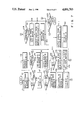
- FIG. 5 is a block diagram of the VPS signal determination circuit of FIG. 4;
- FIGS. 6A and 6B are a first embodiment flowchart for determining VPS signals by means of the VPS signal determination circuit
- FIG. 7 is a second embodiment flowchart for determining VPS signals by means of the VPS signal determination circuit.
- FIGS. 8A through 8C show examples of the determination of VPS signals according to the VPS signal determination circuit of FIG. 5.
- a television signal received by receiving circuit 1 through antenna 1a is applied to detecting circuit 2, VTR 9 and TV 10.
- Detecting circuit 2 detects a VPS signal from the television signal and outputs the VPS signal to a decoder 3.
- the VPS signal decoded in decoder 3 is applied to determination circuit 4.
- Determination circuit 4 determines whether or not the decoded VPS signal is a VPS signal to be used to control VTR 9 and TV 10.
- a program code is input by program code input unit 8 and then stored in memory 7.
- determination circuit 4 determines that the VPS signal is to be used for controlling VTR 9 and TV 10
- a program code corresponding to the VPS signal is compared with the program code read out from memory 7 by comparing circuit 5.
- Control circuit 6 is formed of a microprocessor and the like and produces a control signal to operate VTR 9 and TV 10 in accordance with the comparative result output from comparing circuit 5.
- VTR 9 and TV 10 respond to the control signal so that the former operates in the recording mode and the latter turns on, for example.
- determination circuit 4 comprises input buffer 11, memory buffers 12 and 13, no-signal counter 14, error counter 15, determination process circuit 21 and controller 22.
- Determination circuit 4 performs the determination of VPS signals in accordance with such flowcharts as shown in FIGS. 6A and 6B and FIG. 7.
- a VPS signal is detected from a television signal and then input into input buffer 11 (step F1).
- step F2 determination process circuit 21 determines whether the VPS signal input into input buffer 11 is a no-signal or not.
- no-signal counter 14 is incremented by one (step F3).
- No-signal counter 14 is designed to overflow when over n no-signals are successively input, that is, when no-signal counter 14 are counted over n times.
- step F4 the status of no-signal counter 14 is determined.
- the no-signal counter 14 overflows, the no-signal is loaded into memory buffer 13 (step F5).
- the no-signal stored in memory buffer 13 is used as a VPS signal for controlling VTR 9 and TV 10 and thus output to comparing circuit 5 (step F6).
- step F7 When the VPS signal input into input buffer 11 is a normal signal, no-signal counter 14 is initialized (step F7) and a comparison is made between the VPS signal stored in input buffer 11 and the VPS signal stored in memory buffer 13 (step F8). When no coincidence occurs between the VPS signals, another comparison is made between the VPS signal stored in input buffer 11 and the VPS signal stored in memory buffer 12 (step F9). When no coincidence occurs between the VPS signals in step F9, the VPS signal stored in input buffer 11 is regarded as a new input signal and loaded into memory buffer 12 (step F10).
- step F29 If a twice-coincidence flag representing that two normal VPS signals of the same type are successively input and a triple-coincidence flag representing that three normal VPS signals of the same type are successively input have both been set in determination process circuit 21, these flags are reset in step F29. Further, error counter 15 is incremented by one (step F11).
- step F9 when a coincidence occurs between the VPS signal stored in input buffer 11 and the VPS signal stored in memory buffer 12, the VPS signal in input buffer 11 is loaded into memory buffer 13 (step F12), and the twice-coincidence flag is set (step F13).
- step F8 when a coincidence occurs between the VPS signal in input buffer 11 and the VPS signal in memory buffer 13, the VPS signal in input buffer 11 is compared with the VPS signal in memory buffer 12 (step F14). When no coincidence occurs between the VPS signals, the VPS signal in input buffer 11 is loaded into memory buffer 12 (step F15). The twice-coincidence flag is reset in step F16, and error counter 15 is incremented by one in step F11.
- determination process circuit 21 determines whether or not the twice-coincidence flag is set in step F17. If the flag has already been set, it is determined that the same normal VPS signals have been input successively three times, or a triple-coincidence has occurred. Thus the triple-coincidence flag is set in step F18.
- the VPS signal in memory buffer 13 is output to comparing circuit 5 as the VPS signal adapted for controlling VTR 9 and TV 10 (step F19). Error counter 15 is initialized (step F20), and the twice-coincidence flag is reset (step F21).
- step F22 determination process circuit 21 determines whether or not the triple-coincidence flag is set. If the triple-coincidence flag is set in step F22, the operations of steps F18 through F21 are carried out. If no triple-coincidence flag is set, then the twice-coincidence flag is set (step F23).
- error counter 15 When various kinds of normal VPS signals are input into input buffer 11, error counter 15 in incremented by one each time the VPS signal changes in kind (step F11). If error counter 15 exceeds a predetermined count, i.e,. overflow in step F24, then a determination of occurrence of an abnormal input state is made so that a no-signal is loaded into memory buffer 13 (step F25). The VPS signal in memory buffer 13 is output to comparing circuit 5 as a VPS signal used for controlling VTR 9 and TV 10 (step F26). Moreover, error counter 15 is initialized (step F27).
- step F28 The above operations are performed at regular intervals and continued for a predetermined period.
- a VPS signal is detected from a television signal and input into input buffer 11 (step A1).
- determination process circuit 21 determines whether or not the VPS signal input into input buffer 11 is a no-signal.
- no-signal counter 14 is incremented by one (step A3).
- No-signal counter 14 is designed to overflow when over n no-signals are successively input into input buffer 11.
- step A4 When no-signal counter 14 overflows (step A4), the no-signal is loaded into memory buffer 13 (step A5) and then the no-signal stored in memory buffer 13 is output to comparing circuit 5 as a VPS signal used for controlling VTR 9 and TV 10 (step A6).
- step A7 When the VPS signal input into input buffer 11 is a normal VPS signal, no-signal counter 14 is initialized (step A7), and the VPS signal in input buffer 11 is compared with the VPS signal in memory buffer 12 (step A8).
- step A8 the VPS signal in input buffer 11 and the VPS signal in memory buffer 12 coincide with each other, a comparison is made between the VPS signal input buffer 11 and the VPS signal in memory buffer 13 (step A9). If a coincidence occurs between the VPS signal in input buffer 11 and the VPS signal in memory buffer 13 in step A9, then it is determined that the same normal VPS signals have successively been input three times.
- the VPS signal in memory buffer 13 is output to comparing circuit 5 as a VPS signal used for controlling VTR 9 and TV 10 (step A13).
- error counter 15 is initialized (step A12).
- step A9 If no coincidence occurs between the VPS signal in input buffer 11 and the VPS signal in memory buffer 13 in step A9, then the VPS signal in memory buffer 12 is loaded into memory buffer 13 (step A13), and the VPS signal in input buffer 11 is loaded into memory buffer 12 (step A14).
- step A8 If no coincidence occurs between the VPS signal in input buffer 11 and the VPS signal in memory buffer 12 in step A8, then the VPS signal in memory buffer 12 is loaded into memory buffer 13 (step A15), and the VPS signal in input buffer 11 is loaded into memory buffer 12 (step A16). Further, error counter 15 is incremented by one (step A17).
- step A18 when error counter 15 exceeds a predetermined count, i.e., error counter 15 overflows, the no-signal is loaded into memory buffer 13 (step A19), and the VPS signal in memory buffer 13 is output to comparing circuit 5 (step A20). Further, error counter 15 is initialized (step A21).
- step A22 The above operations are performed at regular intervals and continued for a predetermined period.
- VPS signals used for controlling a VTR and a TV are regarded as no-signals.
- FIG. 8B when three signals (program A) are input in succession (including the case where under n no-signals are successively input between the signals (program A), the signals are regarded as VPS signals used for controlling VTR and TV.
- FIG. 8C when a signal for program B is input between signals (program A), the continuity of signals (program A) will be lost.
- the signals (program A) are regarded as the VPS signals used for controlling VTR and TV.
- the present invention may be applied to the determination of four or five VPS signals which are successively input. In this case, three or four memory buffers will be needed.
Abstract
Description
Claims (8)
Applications Claiming Priority (2)
| Application Number | Priority Date | Filing Date | Title |
|---|---|---|---|
| JP62246034A JPS6489784A (en) | 1987-09-30 | 1987-09-30 | Video program identifying signal deciding device |
| JP62-246034 | 1987-09-30 |
Publications (1)
| Publication Number | Publication Date |
|---|---|
| US4891703A true US4891703A (en) | 1990-01-02 |
Family
ID=17142465
Family Applications (1)
| Application Number | Title | Priority Date | Filing Date |
|---|---|---|---|
| US07/247,604 Expired - Fee Related US4891703A (en) | 1987-09-30 | 1988-09-22 | Method and system for determining video program system signals |
Country Status (4)
| Country | Link |
|---|---|
| US (1) | US4891703A (en) |
| EP (1) | EP0310046B1 (en) |
| JP (1) | JPS6489784A (en) |
| DE (1) | DE3853247T2 (en) |
Cited By (18)
| Publication number | Priority date | Publication date | Assignee | Title |
|---|---|---|---|---|
| US5003390A (en) * | 1990-03-26 | 1991-03-26 | Pbse Enterprises, Inc. | Search and lock technique for reliable acquisition of data transmitted via television signals |
| EP0449552A2 (en) * | 1990-03-28 | 1991-10-02 | Sony Corporation | System for distributing broadcasting material |
| US5262859A (en) * | 1991-04-17 | 1993-11-16 | Victor Company Of Japan, Ltd. | Video signal transmitter/receiver |
| US5296931A (en) * | 1991-03-11 | 1994-03-22 | Samsung Electronics Co., Ltd. | Channel selecting method for programs of the same category |
| WO1994017629A1 (en) * | 1991-08-12 | 1994-08-04 | Keen Yoke Yee | Automatic tuning radio/tv using filtered seek |
| US5430552A (en) * | 1989-09-07 | 1995-07-04 | U.S. Philips Corporation | Device for programming a video recorder and video recorder comprising the device |
| US5469207A (en) * | 1989-12-06 | 1995-11-21 | British Broadcasting Corporation | Method of labelling a broadcast signal including transmitting a sequence of program labels |
| US5568179A (en) * | 1992-05-19 | 1996-10-22 | Thomas Consumer Electronics, S.A. | Method and apparatus for device control by data transmission in TV lines |
| US5579061A (en) * | 1993-05-13 | 1996-11-26 | U.S. Philips Corporation | Transmitter for transmitting tuning data in a television signal and receiver for receiving same |
| US5684541A (en) * | 1993-05-13 | 1997-11-04 | U.S. Philips Corporation | Transmitter station for transmitting a plurality of television programs, and receiver for receiving the programs |
| US5701593A (en) * | 1989-08-25 | 1997-12-23 | Deutsche Thomson-Brandt Gmbh | Method and means for the transmitter-side controller operation of a receiver-side device |
| US5812206A (en) * | 1990-05-30 | 1998-09-22 | British Broadcasting Corporation | Broadcast receiver system |
| US5887243A (en) | 1981-11-03 | 1999-03-23 | Personalized Media Communications, L.L.C. | Signal processing apparatus and methods |
| US6445424B1 (en) * | 1998-06-26 | 2002-09-03 | Deutsche Thomson-Brandt Gmbh | Method and apparatus for multistandard video data acquisition |
| US20060140585A1 (en) * | 2004-12-23 | 2006-06-29 | Ati Technologies Inc. | Detection of copy protection indicators or redistribution control indicators in an analog video signal |
| US20090251610A1 (en) * | 2008-04-08 | 2009-10-08 | Hsin-Chung Wang | Vertical blanking interval slicer and related method |
| US7769344B1 (en) | 1981-11-03 | 2010-08-03 | Personalized Media Communications, Llc | Signal processing apparatus and methods |
| USRE47642E1 (en) | 1981-11-03 | 2019-10-08 | Personalized Media Communications LLC | Signal processing apparatus and methods |
Citations (7)
| Publication number | Priority date | Publication date | Assignee | Title |
|---|---|---|---|---|
| JPS5724179A (en) * | 1980-05-31 | 1982-02-08 | Blaupunkt Werke Gmbh | Additional information transmitting method and radio broadcasting receiver |
| DE3038088A1 (en) * | 1980-10-09 | 1982-04-15 | Institut für Rundfunktechnik GmbH, 8000 München | Data receiver for video signal processing appts. - has capacity for handling digital data of varying length and code format |
| US4479146A (en) * | 1982-03-08 | 1984-10-23 | Discovision Associates | Vertical code verifier |
| DE3341412C1 (en) * | 1983-11-15 | 1985-05-30 | Institut für Rundfunktechnik GmbH, 8000 München | Method for receiving periodically repeated coded information which is transmitted within a television signal |
| DE3439941C1 (en) * | 1984-11-02 | 1985-08-29 | Institut für Rundfunktechnik GmbH, 8000 München | Method for the reception of periodically repeated coded information which is transmitted within a television signal |
| DE3511737A1 (en) * | 1985-03-30 | 1986-10-09 | Standard Elektrik Lorenz Ag, 7000 Stuttgart | Method for outputting a programme identification data word for evaluation in a receiving set |
| US4706121A (en) * | 1985-07-12 | 1987-11-10 | Patrick Young | TV schedule system and process |
Family Cites Families (2)
| Publication number | Priority date | Publication date | Assignee | Title |
|---|---|---|---|---|
| DE3328001C2 (en) * | 1983-08-03 | 1987-05-07 | Institut für Rundfunktechnik GmbH, 8000 München | Device for automatically switching the recording mode of a video recorder on and off |
| DE3623108C1 (en) * | 1986-07-09 | 1987-10-15 | Inst Rundfunktechnik Gmbh | Method for contribution- or time-controlled recording of television programme contributions |
-
1987
- 1987-09-30 JP JP62246034A patent/JPS6489784A/en active Pending
-
1988
- 1988-09-22 US US07/247,604 patent/US4891703A/en not_active Expired - Fee Related
- 1988-09-28 EP EP88116030A patent/EP0310046B1/en not_active Expired - Lifetime
- 1988-09-28 DE DE3853247T patent/DE3853247T2/en not_active Expired - Fee Related
Patent Citations (8)
| Publication number | Priority date | Publication date | Assignee | Title |
|---|---|---|---|---|
| JPS5724179A (en) * | 1980-05-31 | 1982-02-08 | Blaupunkt Werke Gmbh | Additional information transmitting method and radio broadcasting receiver |
| DE3038088A1 (en) * | 1980-10-09 | 1982-04-15 | Institut für Rundfunktechnik GmbH, 8000 München | Data receiver for video signal processing appts. - has capacity for handling digital data of varying length and code format |
| US4479146A (en) * | 1982-03-08 | 1984-10-23 | Discovision Associates | Vertical code verifier |
| DE3341412C1 (en) * | 1983-11-15 | 1985-05-30 | Institut für Rundfunktechnik GmbH, 8000 München | Method for receiving periodically repeated coded information which is transmitted within a television signal |
| DE3439941C1 (en) * | 1984-11-02 | 1985-08-29 | Institut für Rundfunktechnik GmbH, 8000 München | Method for the reception of periodically repeated coded information which is transmitted within a television signal |
| DE3511737A1 (en) * | 1985-03-30 | 1986-10-09 | Standard Elektrik Lorenz Ag, 7000 Stuttgart | Method for outputting a programme identification data word for evaluation in a receiving set |
| US4706121A (en) * | 1985-07-12 | 1987-11-10 | Patrick Young | TV schedule system and process |
| US4706121B1 (en) * | 1985-07-12 | 1993-12-14 | Insight Telecast, Inc. | Tv schedule system and process |
Cited By (115)
| Publication number | Priority date | Publication date | Assignee | Title |
|---|---|---|---|---|
| US9043859B1 (en) | 1981-11-02 | 2015-05-26 | Personalized Media Communications, Llc | Signal processing apparatus and methods |
| US7865920B1 (en) | 1981-11-03 | 2011-01-04 | Personalized Media Communications LLC | Signal processing apparatus and methods |
| USRE47642E1 (en) | 1981-11-03 | 2019-10-08 | Personalized Media Communications LLC | Signal processing apparatus and methods |
| USRE48682E1 (en) | 1981-11-03 | 2021-08-10 | Personalized Media Communications LLC | Providing subscriber specific content in a network |
| USRE48633E1 (en) | 1981-11-03 | 2021-07-06 | Personalized Media Communications LLC | Reprogramming of a programmable device of a specific version |
| USRE48565E1 (en) | 1981-11-03 | 2021-05-18 | Personalized Media Communications LLC | Providing a subscriber specific solution in a computer network |
| USRE48484E1 (en) | 1981-11-03 | 2021-03-23 | Personalized Media Communications, Llc | Signal processing apparatus and methods |
| US10715835B1 (en) | 1981-11-03 | 2020-07-14 | John Christopher Harvey | Signal processing apparatus and methods |
| US10616638B1 (en) | 1981-11-03 | 2020-04-07 | Personalized Media Communications LLC | Signal processing apparatus and methods |
| US10609425B1 (en) | 1981-11-03 | 2020-03-31 | Personalized Media Communications, L.L.C. | Signal processing apparatus and methods |
| USRE47867E1 (en) | 1981-11-03 | 2020-02-18 | Personalized Media Communications LLC | Signal processing apparatus and methods |
| US10523350B1 (en) | 1981-11-03 | 2019-12-31 | Personalized Media Communications LLC | Signal processing apparatus and methods |
| US7870581B1 (en) | 1981-11-03 | 2011-01-11 | Personalized Media Communications, Llc | Signal processing apparatus and methods |
| US5887243A (en) | 1981-11-03 | 1999-03-23 | Personalized Media Communications, L.L.C. | Signal processing apparatus and methods |
| US10334292B1 (en) | 1981-11-03 | 2019-06-25 | Personalized Media Communications LLC | Signal processing apparatus and methods |
| US9674560B1 (en) | 1981-11-03 | 2017-06-06 | Personalized Media Communications LLC | Signal processing apparatus and methods |
| US9294205B1 (en) | 1981-11-03 | 2016-03-22 | Personalized Media Communications LLC | Signal processing apparatus and methods |
| US9210370B1 (en) | 1981-11-03 | 2015-12-08 | Personalized Media Communications LLC | Signal processing apparatus and methods |
| US9038124B1 (en) | 1981-11-03 | 2015-05-19 | Personalized Media Communications, Llc | Signal processing apparatus and methods |
| US7734251B1 (en) | 1981-11-03 | 2010-06-08 | Personalized Media Communications, Llc | Signal processing apparatus and methods |
| US7747217B1 (en) | 1981-11-03 | 2010-06-29 | Personalized Media Communications, Llc | Signal processing apparatus and methods |
| US7752650B1 (en) | 1981-11-03 | 2010-07-06 | Personalized Media Communications, Llc | Signal processing apparatus and methods |
| US7752649B1 (en) | 1981-11-03 | 2010-07-06 | Personalized Media Communications, Llc | Signal processing apparatus and methods |
| US7761890B1 (en) | 1981-11-03 | 2010-07-20 | Personalized Media Communications, Llc | Signal processing apparatus and methods |
| US7764685B1 (en) | 1981-11-03 | 2010-07-27 | Personalized Media Communications, L.L.C. | Signal processing apparatus and methods |
| US7769170B1 (en) | 1981-11-03 | 2010-08-03 | Personalized Media Communications, Llc | Signal processing apparatus and methods |
| US7769344B1 (en) | 1981-11-03 | 2010-08-03 | Personalized Media Communications, Llc | Signal processing apparatus and methods |
| US7774809B1 (en) | 1981-11-03 | 2010-08-10 | Personalized Media Communications, Llc | Signal processing apparatus and method |
| US7783252B1 (en) | 1981-11-03 | 2010-08-24 | Personalized Media Communications, Llc | Signal processing apparatus and methods |
| US7784082B1 (en) | 1981-11-03 | 2010-08-24 | Personalized Media Communications, Llc | Signal processing apparatus and methods |
| US7793332B1 (en) | 1981-11-03 | 2010-09-07 | Personalized Media Communications, Llc | Signal processing apparatus and methods |
| US7797717B1 (en) | 1981-11-03 | 2010-09-14 | Personalized Media Communications, Llc | Signal processing apparatus and methods |
| US7801304B1 (en) | 1981-11-03 | 2010-09-21 | Personalized Media Communications, Llc | Signal processing apparatus and methods |
| US7805748B1 (en) | 1981-11-03 | 2010-09-28 | Personalized Media Communications, Llc | Signal processing apparatus and methods |
| US7805738B1 (en) | 1981-11-03 | 2010-09-28 | Personalized Media Communications, Llc | Signal processing apparatus and methods |
| US7810115B1 (en) | 1981-11-03 | 2010-10-05 | Personalized Media Communications, Llc | Signal processing apparatus and methods |
| US7814526B1 (en) | 1981-11-03 | 2010-10-12 | Personalized Media Communications, Llc | Signal processing apparatus and methods |
| US7818778B1 (en) | 1981-11-03 | 2010-10-19 | Personalized Media Communications, Llc | Signal processing apparatus and methods |
| US7818777B1 (en) | 1981-11-03 | 2010-10-19 | Personalized Media Communications, Llc | Signal processing apparatus and methods |
| US7818776B1 (en) | 1981-11-03 | 2010-10-19 | Personalized Media Communications, Llc | Signal processing apparatus and methods |
| US7817208B1 (en) | 1981-11-03 | 2010-10-19 | Personalized Media Communications, Llc | Signal processing apparatus and methods |
| US7823175B1 (en) | 1981-11-03 | 2010-10-26 | Personalized Media Communications LLC | Signal processing apparatus and methods |
| US7827587B1 (en) | 1981-11-03 | 2010-11-02 | Personalized Media Communications, Llc | Signal processing apparatus and methods |
| US7827586B1 (en) | 1981-11-03 | 2010-11-02 | Personalized Media Communications, Llc | Signal processing apparatus and methods |
| US7831204B1 (en) | 1981-11-03 | 2010-11-09 | Personalized Media Communications, Llc | Signal processing apparatus and methods |
| US7836480B1 (en) | 1981-11-03 | 2010-11-16 | Personalized Media Communications, Llc | Signal processing apparatus and methods |
| US7840976B1 (en) | 1981-11-03 | 2010-11-23 | Personalized Media Communications, Llc | Signal processing apparatus and methods |
| US7844995B1 (en) | 1981-11-03 | 2010-11-30 | Personalized Media Communications, Llc | Signal processing apparatus and methods |
| US7849493B1 (en) | 1981-11-03 | 2010-12-07 | Personalized Media Communications, Llc | Signal processing apparatus and methods |
| US7849480B1 (en) | 1981-11-03 | 2010-12-07 | Personalized Media Communications LLC | Signal processing apparatus and methods |
| US7849479B1 (en) | 1981-11-03 | 2010-12-07 | Personalized Media Communications, Llc | Signal processing apparatus and methods |
| US7856649B1 (en) | 1981-11-03 | 2010-12-21 | Personalized Media Communications, Llc | Signal processing apparatus and methods |
| US7861263B1 (en) | 1981-11-03 | 2010-12-28 | Personalized Media Communications, Llc | Signal processing apparatus and methods |
| US7860131B1 (en) | 1981-11-03 | 2010-12-28 | Personalized Media Communications, Llc | Signal processing apparatus and methods |
| US7861278B1 (en) | 1981-11-03 | 2010-12-28 | Personalized Media Communications, Llc | Signal processing apparatus and methods |
| US7860249B1 (en) | 1981-11-03 | 2010-12-28 | Personalized Media Communications LLC | Signal processing apparatus and methods |
| US7864248B1 (en) | 1981-11-03 | 2011-01-04 | Personalized Media Communications, Llc | Signal processing apparatus and methods |
| US8973034B1 (en) | 1981-11-03 | 2015-03-03 | Personalized Media Communications LLC | Signal processing apparatus and methods |
| US7864956B1 (en) | 1981-11-03 | 2011-01-04 | Personalized Media Communications, Llc | Signal processing apparatus and methods |
| US8914825B1 (en) | 1981-11-03 | 2014-12-16 | Personalized Media Communications LLC | Signal processing apparatus and methods |
| US7889865B1 (en) | 1981-11-03 | 2011-02-15 | Personalized Media Communications, L.L.C. | Signal processing apparatus and methods |
| US7908638B1 (en) | 1981-11-03 | 2011-03-15 | Personalized Media Communications LLC | Signal processing apparatus and methods |
| US7926084B1 (en) | 1981-11-03 | 2011-04-12 | Personalized Media Communications LLC | Signal processing apparatus and methods |
| US7940931B1 (en) | 1981-11-03 | 2011-05-10 | Personalized Media Communications LLC | Signal processing apparatus and methods |
| US7953223B1 (en) | 1981-11-03 | 2011-05-31 | Personalized Media Communications, L.L.C. | Signal processing apparatus and methods |
| US8893177B1 (en) | 1981-11-03 | 2014-11-18 | {Personalized Media Communications, LLC | Signal processing apparatus and methods |
| US8869229B1 (en) | 1981-11-03 | 2014-10-21 | Personalized Media Communications, Llc | Signal processing apparatus and methods |
| US7992169B1 (en) | 1981-11-03 | 2011-08-02 | Personalized Media Communications LLC | Signal processing apparatus and methods |
| US8046791B1 (en) | 1981-11-03 | 2011-10-25 | Personalized Media Communications, Llc | Signal processing apparatus and methods |
| US8060903B1 (en) | 1981-11-03 | 2011-11-15 | Personalized Media PMC Communications, L.L.C. | Signal processing apparatus and methods |
| US8112782B1 (en) | 1981-11-03 | 2012-02-07 | Personalized Media Communications, Llc | Signal processing apparatus and methods |
| US8191091B1 (en) | 1981-11-03 | 2012-05-29 | Personalized Media Communications, Llc | Signal processing apparatus and methods |
| US8555310B1 (en) | 1981-11-03 | 2013-10-08 | Personalized Media Communications, Llc | Signal processing apparatus and methods |
| US8558950B1 (en) | 1981-11-03 | 2013-10-15 | Personalized Media Communications LLC | Signal processing apparatus and methods |
| US8559635B1 (en) | 1981-11-03 | 2013-10-15 | Personalized Media Communications, L.L.C. | Signal processing apparatus and methods |
| US8566868B1 (en) | 1981-11-03 | 2013-10-22 | Personalized Media Communications, L.L.C. | Signal processing apparatus and methods |
| US8572671B1 (en) | 1981-11-03 | 2013-10-29 | Personalized Media Communications LLC | Signal processing apparatus and methods |
| US8584162B1 (en) | 1981-11-03 | 2013-11-12 | Personalized Media Communications LLC | Signal processing apparatus and methods |
| US8587720B1 (en) | 1981-11-03 | 2013-11-19 | Personalized Media Communications LLC | Signal processing apparatus and methods |
| US8601528B1 (en) | 1981-11-03 | 2013-12-03 | Personalized Media Communications, L.L.C. | Signal processing apparatus and methods |
| US8607296B1 (en) | 1981-11-03 | 2013-12-10 | Personalized Media Communications LLC | Signal processing apparatus and methods |
| US8613034B1 (en) | 1981-11-03 | 2013-12-17 | Personalized Media Communications, Llc | Signal processing apparatus and methods |
| US8621547B1 (en) | 1981-11-03 | 2013-12-31 | Personalized Media Communications, Llc | Signal processing apparatus and methods |
| US8635644B1 (en) | 1981-11-03 | 2014-01-21 | Personalized Media Communications LLC | Signal processing apparatus and methods |
| US8640184B1 (en) | 1981-11-03 | 2014-01-28 | Personalized Media Communications, Llc | Signal processing apparatus and methods |
| US8646001B1 (en) | 1981-11-03 | 2014-02-04 | Personalized Media Communications, Llc | Signal processing apparatus and methods |
| US8675775B1 (en) | 1981-11-03 | 2014-03-18 | Personalized Media Communications, Llc | Signal processing apparatus and methods |
| US8683539B1 (en) | 1981-11-03 | 2014-03-25 | Personalized Media Communications, Llc | Signal processing apparatus and methods |
| US8711885B1 (en) | 1981-11-03 | 2014-04-29 | Personalized Media Communications LLC | Signal processing apparatus and methods |
| US8713624B1 (en) | 1981-11-03 | 2014-04-29 | Personalized Media Communications LLC | Signal processing apparatus and methods |
| US8739241B1 (en) | 1981-11-03 | 2014-05-27 | Personalized Media Communications LLC | Signal processing apparatus and methods |
| US8752088B1 (en) | 1981-11-03 | 2014-06-10 | Personalized Media Communications LLC | Signal processing apparatus and methods |
| US8804727B1 (en) | 1981-11-03 | 2014-08-12 | Personalized Media Communications, Llc | Signal processing apparatus and methods |
| US8839293B1 (en) | 1981-11-03 | 2014-09-16 | Personalized Media Communications, Llc | Signal processing apparatus and methods |
| US8869228B1 (en) | 1981-11-03 | 2014-10-21 | Personalized Media Communications, Llc | Signal processing apparatus and methods |
| US7966640B1 (en) | 1987-09-11 | 2011-06-21 | Personalized Media Communications, Llc | Signal processing apparatus and methods |
| US7958527B1 (en) | 1987-09-11 | 2011-06-07 | Personalized Media Communications, Llc | Signal processing apparatus and methods |
| US5701593A (en) * | 1989-08-25 | 1997-12-23 | Deutsche Thomson-Brandt Gmbh | Method and means for the transmitter-side controller operation of a receiver-side device |
| US5430552A (en) * | 1989-09-07 | 1995-07-04 | U.S. Philips Corporation | Device for programming a video recorder and video recorder comprising the device |
| US5469207A (en) * | 1989-12-06 | 1995-11-21 | British Broadcasting Corporation | Method of labelling a broadcast signal including transmitting a sequence of program labels |
| US5003390A (en) * | 1990-03-26 | 1991-03-26 | Pbse Enterprises, Inc. | Search and lock technique for reliable acquisition of data transmitted via television signals |
| EP0449552A2 (en) * | 1990-03-28 | 1991-10-02 | Sony Corporation | System for distributing broadcasting material |
| EP0449552A3 (en) * | 1990-03-28 | 1992-12-02 | Sony Corporation | System for distributing broadcasting material |
| US5659877A (en) * | 1990-03-28 | 1997-08-19 | Sony Corporation | System for distributing broadcasting material and identifying segment data |
| US5812206A (en) * | 1990-05-30 | 1998-09-22 | British Broadcasting Corporation | Broadcast receiver system |
| US5296931A (en) * | 1991-03-11 | 1994-03-22 | Samsung Electronics Co., Ltd. | Channel selecting method for programs of the same category |
| US5262859A (en) * | 1991-04-17 | 1993-11-16 | Victor Company Of Japan, Ltd. | Video signal transmitter/receiver |
| WO1994017629A1 (en) * | 1991-08-12 | 1994-08-04 | Keen Yoke Yee | Automatic tuning radio/tv using filtered seek |
| US5568179A (en) * | 1992-05-19 | 1996-10-22 | Thomas Consumer Electronics, S.A. | Method and apparatus for device control by data transmission in TV lines |
| US5684541A (en) * | 1993-05-13 | 1997-11-04 | U.S. Philips Corporation | Transmitter station for transmitting a plurality of television programs, and receiver for receiving the programs |
| US5579061A (en) * | 1993-05-13 | 1996-11-26 | U.S. Philips Corporation | Transmitter for transmitting tuning data in a television signal and receiver for receiving same |
| US6445424B1 (en) * | 1998-06-26 | 2002-09-03 | Deutsche Thomson-Brandt Gmbh | Method and apparatus for multistandard video data acquisition |
| US20060140585A1 (en) * | 2004-12-23 | 2006-06-29 | Ati Technologies Inc. | Detection of copy protection indicators or redistribution control indicators in an analog video signal |
| US7440677B2 (en) * | 2004-12-23 | 2008-10-21 | Ati Technologies Inc. | Detection of copy protection indicators or redistribution control indicators in an analog video signal |
| US20090251610A1 (en) * | 2008-04-08 | 2009-10-08 | Hsin-Chung Wang | Vertical blanking interval slicer and related method |
Also Published As
| Publication number | Publication date |
|---|---|
| EP0310046B1 (en) | 1995-03-08 |
| DE3853247T2 (en) | 1995-06-29 |
| DE3853247D1 (en) | 1995-04-13 |
| JPS6489784A (en) | 1989-04-04 |
| EP0310046A3 (en) | 1991-04-24 |
| EP0310046A2 (en) | 1989-04-05 |
Similar Documents
| Publication | Publication Date | Title |
|---|---|---|
| US4891703A (en) | Method and system for determining video program system signals | |
| US4390901A (en) | Method and apparatus for controlling the operation of a television signal receiver | |
| US5337157A (en) | Copy guard processing detecting apparatus | |
| JPH08289244A (en) | Method and equipment for television signal sorting | |
| US5237319A (en) | Remote control device with learning function | |
| US7697822B2 (en) | Apparatus and method for automatically selecting and recording highlight portions of a broadcast signal | |
| CA1138537A (en) | Synchronizing signal detecting apparatus | |
| US4991025A (en) | Arrangement for automatically switching a videorecorder on and off in the absence of a code signal but in presence of a FBAS signal | |
| US4656604A (en) | Control circuit with recovery protection | |
| CA1303732C (en) | Apparatus for reserving programs at various recording tape running speeds | |
| US4159481A (en) | Synchronizing signal selecting circuit | |
| US5453793A (en) | Method for recording a series program in a video cassette recorder | |
| US5510849A (en) | Circuit and method for generating caption signal in video signal processing system | |
| US6943828B1 (en) | Method and apparatus for providing adaptive horizontal sync detection | |
| US6784943B1 (en) | Auxiliary digital data extractor in a television | |
| US5619336A (en) | Recording apparatus and method for video cassette recorder having snow noise removing function | |
| US3980958A (en) | Signal seeking tuning system with illegal channel detection means | |
| US5990966A (en) | G-code decoder for use with a video tape recorder and method for same | |
| KR0147989B1 (en) | Method for searching in a video cassette recorder | |
| KR100215634B1 (en) | Priority designation reservation recording method | |
| KR100237305B1 (en) | Program time data processor | |
| KR0139085B1 (en) | Self-diagnosting method of tv | |
| KR100286319B1 (en) | Automatic channel selection method for television | |
| KR0134242B1 (en) | Method of receiving korea broadcasting program system data | |
| KR19990051237A (en) | Video cassette recorder control method |
Legal Events
| Date | Code | Title | Description |
|---|---|---|---|
| AS | Assignment |
Owner name: KABUSHIKI KAISHA TOSHIBA, 72 HORIKAWA-CHO, SAIWAI- Free format text: ASSIGNMENT OF ASSIGNORS INTEREST.;ASSIGNOR:NOUDAN, YOSHIMASA;REEL/FRAME:004950/0350 Effective date: 19880912 Owner name: KABUSHIKI KAISHA TOSHIBA, 72 HORIKAWA-CHO, SAIWAI- Free format text: ASSIGNMENT OF ASSIGNORS INTEREST;ASSIGNOR:NOUDAN, YOSHIMASA;REEL/FRAME:004950/0350 Effective date: 19880912 |
|
| FEPP | Fee payment procedure |
Free format text: PAYOR NUMBER ASSIGNED (ORIGINAL EVENT CODE: ASPN); ENTITY STATUS OF PATENT OWNER: LARGE ENTITY |
|
| FPAY | Fee payment |
Year of fee payment: 4 |
|
| FPAY | Fee payment |
Year of fee payment: 8 |
|
| REMI | Maintenance fee reminder mailed | ||
| LAPS | Lapse for failure to pay maintenance fees | ||
| STCH | Information on status: patent discontinuation |
Free format text: PATENT EXPIRED DUE TO NONPAYMENT OF MAINTENANCE FEES UNDER 37 CFR 1.362 |
|
| FP | Lapsed due to failure to pay maintenance fee |
Effective date: 20020102 |