EP0310046A2 - Method and system for determining video program system signals - Google Patents
Method and system for determining video program system signals Download PDFInfo
- Publication number
- EP0310046A2 EP0310046A2 EP88116030A EP88116030A EP0310046A2 EP 0310046 A2 EP0310046 A2 EP 0310046A2 EP 88116030 A EP88116030 A EP 88116030A EP 88116030 A EP88116030 A EP 88116030A EP 0310046 A2 EP0310046 A2 EP 0310046A2
- Authority
- EP
- European Patent Office
- Prior art keywords
- signal
- vps
- video program
- stored
- count value
- Prior art date
- Legal status (The legal status is an assumption and is not a legal conclusion. Google has not performed a legal analysis and makes no representation as to the accuracy of the status listed.)
- Granted
Links
Images


Classifications
-
- H—ELECTRICITY
- H04—ELECTRIC COMMUNICATION TECHNIQUE
- H04N—PICTORIAL COMMUNICATION, e.g. TELEVISION
- H04N7/00—Television systems
- H04N7/08—Systems for the simultaneous or sequential transmission of more than one television signal, e.g. additional information signals, the signals occupying wholly or partially the same frequency band, e.g. by time division
- H04N7/087—Systems for the simultaneous or sequential transmission of more than one television signal, e.g. additional information signals, the signals occupying wholly or partially the same frequency band, e.g. by time division with signal insertion during the vertical blanking interval only
- H04N7/088—Systems for the simultaneous or sequential transmission of more than one television signal, e.g. additional information signals, the signals occupying wholly or partially the same frequency band, e.g. by time division with signal insertion during the vertical blanking interval only the inserted signal being digital
- H04N7/0887—Systems for the simultaneous or sequential transmission of more than one television signal, e.g. additional information signals, the signals occupying wholly or partially the same frequency band, e.g. by time division with signal insertion during the vertical blanking interval only the inserted signal being digital for the transmission of programme or channel identifying signals
Definitions
- the present invention relates to a method and system for determining video program system (VPS) signals detected from television signals.
- VPN video program system
- VPS signal is represented by 1-15 word data
- word data word numbers 11-14
- the word data in current use includes the broadcasting data (the month, day and hour), the nationality code of a broadcasting station, a program source code, etc, which are previously published in a television program guide and assigned to each of programs.
- a TV is turned on and a video tape recorder (VTR) is controlled in a recording mode.
- VTR video tape recorder
- this receiving equipment decodes a received VPS signal and determines whether or not a program source code obtained by the decoding corresponds to a preset program source code. Therefore, it is necessary for the receiving equipment to accurately detect the VPS signal. However, by mixed with noise, the VPS signal may become difficult to detect.
- a example of a determination circuit for VPS signals is shown in German Offenlegungsschrift (Document open for inspection) DE-OS.3,511,737.
- the determination circuit includes a memory, a comparing circuit, and a counter.
- a detected VPS signal is stored in the memory, compared with a next detected VPS signal.
- the counter is incremented by one.
- the counter is reset.
- a count value of the counter is obtained when the same VPS signal is successively detected.
- the determination circuit determines that the VPS signals correspond to a program being broadcast.
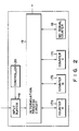
- the another sample of a known determination circuit for VPS signals is shown in Fig. 2.
- the determination circuit determines by using the majority of VPS signals, and includes input buffer 16, counters 17a, 17b and 17c, no-signal counter 18, determination process circuit 19 and controller 20.
- Controller 20 is constructed of a central processing unit (CPU) and the like and controls the timing of access to input buffer 16.
- the determination of VPS signals is performed in accordance with a flowchart as shown in Fig. 3.
- a VPS signal is detected from a television signal and input into input buffer 16 at a specified timing by a control signal output from controller 20 (step S1).
- the VPS signal input into input buffer 16 is regarded as a VPS signal for a program A, counter 17a is incremented by one (step S5).
- Determination process circuit 19 determines whether or not a next VPS signal input into input buffer 16 coincides with the VPS signal for the program A (step S2). In step S2, when the next VPS signal corresponds to the program A, counter 17a is incremented by one (Step S5).
- step S2 if the next VPS signal does not correspond to the program A, the next VPS signal is regarded as a VPS signal for a program B, counter 17b is incremented by one (step S6).
- determination process circuit 19 determines whether or not a new VPS signal input into input buffer 16 coincides with the VPS signal for programs A or B (step 2, step S3).
- step S5 When the new VPS signal corresponds to the program A, counter 17a is incremented by one (step S5).
- step S6 When the new VPS signal corresponds to the program B, counter 17b is incremented by one (step S6).
- step S7 If the new VPS signal does not correspond to the programs A and B, the new VPS signal is regarded as a VPS signal for a program C, counter 17c is incremented by one (step S7).
- step S7 When a VPS signal input into input buffer 16 corresponds to the program C (step S4), step S7 is perfomed.
- no-signal counter 18 is incremented by one (step S8).
- step S9 The above process is performed at regular intervals and continued for a predetermined period.
- step S10 is then performed.
- step S10 the VPS signal is detected which corresponds to a counter having a maximum count value among counters 17a, 17b and 17c and no-signal counter 18. For example, when the count value of counter 17a is maximum, the VPS signal for program A has been detected most frequently during the predetermined period. As a result, the conventional determination circuit deter necessarilymines that a program being broadcast is A.
- VPS signals when television signals are received unstably, VPS signals will also become unstable and thus may not be determined. In such a case, the determination procedure as shown in Fig. 3 will fail to determine any of VPS signals corresponding to programs in each of steps S2, S3 and S4, increasing the count value of no-signal counter 18. For example, if normal VPS signals are detected only two times during five determination processes, then no-signal counter 18 will count three times. Thus, determination circuit would be determined that the VPS signal is not superimposed upon a television signal being received.
- an apparatus which is capable of accurately detecting and determining VPS signals from received television signals.
- a method for determining a video program system signal detected from a television signal comprising the steps of: storing the video program system signal detected from the television signal; determining whether or not the stored video program system signal is a no-signal; counting a no-signal count value when the stored video program system signal is the no-signal; outputting the no-signal when the no-signal count value exceeds a first predetermined count value; determining whether or not the stored video program system signal is a normal signal; counting an error count value when different video program system signals are stored; outputting the no-signal when the error count value exceeds a second predetermined count value; and outputting the stored video program system signal when the predetermined number of normal signals is continuously stored except for the storage of the predetermined number of no-signals.
- a system for determining a video program system signal detected from a television signal comprising: input buffer means for storing the video program system signal detected from the television signal; determining means for determining the video program system signal stored in the input buffer means; memory buffer means for storing the video program system signal stored in the input buffer means in accordance with a determination result obtained by the determining means; error counter means for counting an error count value in accordance with the determination result obtained by the determining means; and no-signal counter means for counting a no-signal count value in accordance with the determination result obtained by the determining means.
- a television signal received by receiving circuit 1 through antenna 1a is applied to detecting circuit 2, VTR 9 and TV 10.
- Detecting circuit 2 detects a VPS signal from the television signal and outputs the VPS signal to a decoder 3.
- the VPS signal decoded in decoder 3 is applied to determination circuit 4.
- Determination circuit 4 determines whether or not the decoded VPS signal is a VPS signal to be used to control VTR 9 and TV 10.
- a program code is input by program code input unit 8 and then stored in memory 7.
- control circuit 6 is formed of a microprocessor and the like and produces a control signal to operate VTR 9 and TV 10 in accordance with the comparative result output from comparing circuit 5.
- VTR 9 and TV 10 respond to the control signal so that the former operates in the recording mode and the latter turns on, for example.
- determination circuit 4 comprises input buffer 11, memory buffers 12 and 13, no-signal counter 14, error counter 15, determination process circuit 21 and controller 22. Determination circuit 4 performs the determination of VPS signals in accordance with such flowcharts as shown in Figs. 6A and 6B and Fig. 7.
- a VPS signal is detected from a television signal and then input into input buffer 11 (step F1).
- step F2 determination process circuit 21 determines whether the VPS signal input into input buffer 11 is a no-signal or not.
- no-signal counter 14 is incremented by one (step F3).
- No-signal counter 14 is designed to overflow when over n no-signals are successively input, that is, when no-signal counter 14 are counted over n times.
- step F4 the status of no-signal counter 14 is determined.
- the no-signal counter 14 overflows, the no-signal is loaded into memory buffer 13 (step F5).
- the no-signal stored in memory buffer 13 is used as a VPS signal for controlling VTR 9 and TV 10 and thus output to comparing circuit 5 (step F6).
- no-signal counter 14 is initialized (step F7) and a comparison is made between the VPS signal stored in input buffer 11 and the VPS signal stored in memory buffer 13 (step F8).
- step F8 When no coincidence occurs between the VPS signals, another comparison is made between the VPS signal stored in input buffer 11 and the VPS signal stored in memory buffer 12 (step F9).
- step F9 When no coincidence occurs between the VPS signals in step F9, the VPS signal stored in input buffer 11 is regarded as a new input signal and loaded into memory buffer 12 (step F10).
- step F29 If a twice-coincidence flag representing that two normal VPS signals of the same type are successively input and a triple-coincidence flag representing that three normal VPS signals of the same type are successively input have both been set in determination process circuit 21, these flags are reset in step F29. Further, error counter 15 is incremented by one (step F11).
- step F9 when a coincidence occurs between the VPS signal stored in input buffer 11 and the VPS signal stored in memory buffer 12, the VPS signal in input buffer 11 is loaded into memory buffer 13 (step F12), and the twice-coincidence flag is set (step F13).
- step F8 when a coincidence occurs between the VPS signal in input buffer 11 and the VPS signal in memory buffer 13, the VPS signal in input buffer 11 is compared with the VPS signal in memory buffer 12 (step F14). When no coincidence occurs between the VPS signals, the VPS signal in input buffer 11 is loaded into memory buffer 12 (step F15). The twice-coincidence flag is reset in step F16, and error counter 15 is incremented by one in step F11.
- determination process circuit 21 determines whether or not the twice-coincidence flag is set in step F17. If the flag has already been set, it is determined that the same normal VPS signals have been input successively three times, or a triple-coincidence has occurred. Thus the triple-coincidence flag is set in step F18.
- the VPS signal in memory buffer 13 is output to comparing circuit 5 as the VPS signal adapted for controlling VTR 9 and TV 10 (step F19) . Error counter 15 is initialized (step F20), and the twice-coincidence flag is reset (step F21) .
- step F22 determination process circuit 21 determines whether or not the triple-coincidence flag is set. If the triple-coincidence flag is set in step F22, the operations of steps F18 through F21 are carried out. If no triple-coincidence flag is set, then the twice-coincidence flag is set (step F23).
- error counter 15 When various kinds of normal VPS signals are input into input buffer 11, error counter 15 is incremented by one each time the VPS signal changes in kind (step F11). If error counter 15 exceeds a predetermined count, i.e., overflows in step F24, then a determination of occurrence of an abnormal input state is made so that a no-signal is loaded into memory buffer 13 (step F25). The VPS signal in memory buffer 13 is output to comparing circuit 5 as a VPS signal used for controlling VTR 9 and TV 10 (step F26). Moreover, error counter 15 is initialized (step F27).
- step F28 The above operations are performed at regular intervals and continued for a predetermined period.
- a VPS signal is detected from a television signal and input into input buffer 11 (step A1).
- determination process circuit 21 determines whether or not the VPS signal input into input buffer 11 is a no-signal.
- no-signal counter 14 is incremented by one (step A3).
- No-signal counter 14 is designed to overflow when over n no-signals are successively input into input buffer 11.
- step A4 When no-signal counter 14 overflows (step A4), the no-signal is loaded into memory buffer 13 (step A5) and then the no-signal stored in memory buffer 13 is output to comparing circuit 5 as a VPS signal used for controlling VTR 9 and TV 10 (step A6).
- step A7 When the VPS signal input into input buffer 11 is a normal VPS signal, no-signal counter 14 is initialized (step A7), and the VPS signal in input buffer 11 is compared with the VPS signal in memory buffer 12 (step A8).
- step A8 the VPS signal in input buffer 11 and the VPS signal in memory buffer 12 coincide with each other, a comparison is made between the VPS signal input buffer 11 and the VPS signal in memory buffer 13 (step A9). If a coincidence occurs between the VPS signal in input buffer 11 and the VPS signal in memory buffer 13 in step A9, then it is determined that the same normal VPS signals have successively been input three times. As a result, the VPS signal in memory buffer 13 is output to comparing circuit 5 as a VPS signal used for controlling VTR 9 and TV 10 (step A13). And, error counter 15 is initialized (step A12).
- step A9 If no coincidence occurs between the VPS signal in input buffer 11 and the VPS signal in memory buffer 13 in step A9, then the VPS signal in memory buffer 12 is loaded into memory buffer 13 (step A13), and the VPS signal in input buffer 11 is loaded into memory buffer 12 (step A14).
- step A8 If no coincidence occurs between the VPS signal in input buffer 11 and the VPS signal in memory buffer 12 in step A8, then the VPS signal in memory buffer 12 is loaded into memory buffer 13 (step A15), and the VPS signal in input buffer 11 is loaded into memory buffer 12 (step A16). Further, error counter 15 is incremented by one (step A17).
- step A18 when error counter 15 exceeds a predetermined count, i.e., error counter 15 overflows, the no-signal is loaded into memory buffer 13 (step A19), and the VPS signal in memory buffer 13 is output to comparing circuit 5 (step A20). Further, error counter 15 is initialized (step A21).
- step A22 The above operations are performed at regular intervals and continued for a predetermined period.
- VPS signals used for controlling a VTR and a TV are regarded as no-signals.
- Fig. 8B when three signals (program A) are input in succession (including the case where under n no-signals are successively input between the signals (program A), the signals are regarded as VPS signals used for controlling VTR and TV.
- Fig. 8C when a signal for program B is input between signals (program A), the continuity of signals (program A) will be lost.
- the signals (program A) are regarded as the VPS signals used for controlling VTR and TV.
- the present invention may be applied to the determination of four or five VPS signals which are successively input. In this case, three or four memory buffers will be needed.
Abstract
Description
- The present invention relates to a method and system for determining video program system (VPS) signals detected from television signals.
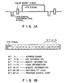
- It has been put to practical use to allocate a VPS signal to each of television programs and to detect and determine the VPS signal (see Fig. 1A), which has been superimposed on a specific line in a vertical-return interval of a television signal prior to the start of broadcasting of the program, in order to control various types of TV signal receiving equipment. As shown in Fig. 1B, the VPS signal is represented by 1-15 word data, and the word data (word numbers 11-14) in current use includes the broadcasting data (the month, day and hour), the nationality code of a broadcasting station, a program source code, etc, which are previously published in a television program guide and assigned to each of programs. For example, by means of the VPS signal a TV is turned on and a video tape recorder (VTR) is controlled in a recording mode.
- To control TV signal receiving equipment by means of VPS signals as described above, this receiving equipment decodes a received VPS signal and determines whether or not a program source code obtained by the decoding corresponds to a preset program source code. Therefore, it is necessary for the receiving equipment to accurately detect the VPS signal. However, by mixed with noise, the VPS signal may become difficult to detect.
- A example of a determination circuit for VPS signals is shown in German Offenlegungsschrift (Document open for inspection) DE-OS.3,511,737. The determination circuit includes a memory, a comparing circuit, and a counter. A detected VPS signal is stored in the memory, compared with a next detected VPS signal. When the VPS signal stored in the memory coincides with the next detected VPS signal, the counter is incremented by one. When no coincidence occurs between these VPS signals, the counter is reset. By the above process, a count value of the counter is obtained when the same VPS signal is successively detected. When a predetermined count value is counted by the counter, the determination circuit determines that the VPS signals correspond to a program being broadcast. The another sample of a known determination circuit for VPS signals is shown in Fig. 2. The determination circuit determines by using the majority of VPS signals, and includes
input buffer 16,counters 17a, 17b and 17c, no-signal counter 18,determination process circuit 19 andcontroller 20.Controller 20 is constructed of a central processing unit (CPU) and the like and controls the timing of access toinput buffer 16. The determination of VPS signals is performed in accordance with a flowchart as shown in Fig. 3. - In Fig. 3, when a VPS signal determination process is started, a VPS signal is detected from a television signal and input into
input buffer 16 at a specified timing by a control signal output from controller 20 (step S1). The VPS signal input intoinput buffer 16 is regarded as a VPS signal for a program A, counter 17a is incremented by one (step S5).Determination process circuit 19 determines whether or not a next VPS signal input intoinput buffer 16 coincides with the VPS signal for the program A (step S2). In step S2, when the next VPS signal corresponds to the program A, counter 17a is incremented by one (Step S5). In step S2, if the next VPS signal does not correspond to the program A, the next VPS signal is regarded as a VPS signal for a program B,counter 17b is incremented by one (step S6). Similarly,determination process circuit 19 determines whether or not a new VPS signal input intoinput buffer 16 coincides with the VPS signal for programs A or B (step 2, step S3). When the new VPS signal corresponds to the program A, counter 17a is incremented by one (step S5). When the new VPS signal corresponds to the program B,counter 17b is incremented by one (step S6). If the new VPS signal does not correspond to the programs A and B, the new VPS signal is regarded as a VPS signal for a program C, counter 17c is incremented by one (step S7). When a VPS signal input intoinput buffer 16 corresponds to the program C (step S4), step S7 is perfomed. When the VPS signal input intoinput buffer 16 does not correspond to any one of programs A, B and C, for example, when the VPS signal is a no-signal, no-signal counter 18 is incremented by one (step S8). - The above process is performed at regular intervals and continued for a predetermined period (step S9). When the input of the VPS signal into
input buffer 16 for the predetermined period is completed (step S9), step S10 is then performed. - In step S10, the VPS signal is detected which corresponds to a counter having a maximum count value among
counters 17a, 17b and 17c and no-signal counter 18. For example, when the count value of counter 17a is maximum, the VPS signal for program A has been detected most frequently during the predetermined period. As a result, the conventional determination circuit determines that a program being broadcast is A. - However, the conventional determination procedure for the VPS signals involves the following problems.
- For example, when television signals are received unstably, VPS signals will also become unstable and thus may not be determined. In such a case, the determination procedure as shown in Fig. 3 will fail to determine any of VPS signals corresponding to programs in each of steps S2, S3 and S4, increasing the count value of no-
signal counter 18. For example, if normal VPS signals are detected only two times during five determination processes, then no-signal counter 18 will count three times. Thus, determination circuit would be determined that the VPS signal is not superimposed upon a television signal being received. - From the above, an apparatus is desired which is capable of accurately detecting and determining VPS signals from received television signals.
- It is an object of the present invention to provide a method and system for determining a video program system signal detected from a television signal.
- According to one aspect of the present invention, there is provided a method for determining a video program system signal detected from a television signal, the method comprising the steps of: storing the video program system signal detected from the television signal; determining whether or not the stored video program system signal is a no-signal; counting a no-signal count value when the stored video program system signal is the no-signal; outputting the no-signal when the no-signal count value exceeds a first predetermined count value; determining whether or not the stored video program system signal is a normal signal; counting an error count value when different video program system signals are stored; outputting the no-signal when the error count value exceeds a second predetermined count value; and outputting the stored video program system signal when the predetermined number of normal signals is continuously stored except for the storage of the predetermined number of no-signals.
- According to another aspect of the present invention, there is provided a system for determining a video program system signal detected from a television signal, the system comprising: input buffer means for storing the video program system signal detected from the television signal; determining means for determining the video program system signal stored in the input buffer means; memory buffer means for storing the video program system signal stored in the input buffer means in accordance with a determination result obtained by the determining means; error counter means for counting an error count value in accordance with the determination result obtained by the determining means; and no-signal counter means for counting a no-signal count value in accordance with the determination result obtained by the determining means.
- This invention can be more fully understood from the following detailed description when taken in conjunction with the accompanying drawings, in which:
- Figs. 1A and 1B are diagrams for explaining a general VPS signal;
- Fig. 2 is a block diagram of a conventional VPS signal determination circuit;
- Fig. 3 is an operational flowchart for determining VPS signals used with the conventional determination circuit;
- Fig. 4 shows an arrangement of a system of the present invention;
- Fig. 5 is a block diagram of the VPS signal determination circuit of Fig. 4;
- Figs. 6A and 6B are a first embodiment flowchart for determining VPS signals by means of the VPS signal determination circuit;
- Fig. 7 is a second embodiment flowchart for determining VPS signals by means of the VPS signal determination circuit; and
- Figs. 8A through 8C show examples of the determination of VPS signals according to the VPS signal determination circuit of Fig. 5.
- Referring now to Fig. 4, a television signal received by receiving
circuit 1 through antenna 1a is applied to detectingcircuit 2,VTR 9 andTV 10. Detectingcircuit 2 detects a VPS signal from the television signal and outputs the VPS signal to adecoder 3. The VPS signal decoded indecoder 3 is applied todetermination circuit 4.Determination circuit 4 determines whether or not the decoded VPS signal is a VPS signal to be used to controlVTR 9 and TV 10. On the other hand, a program code is input by programcode input unit 8 and then stored inmemory 7. Whendetermination circuit 4 determines that the VPS signal is to be used for controllingVTR 9 andTV 10, a program code corresponding to the VPS signal is compared with the program code read out frommemory 7 by comparingcircuit 5. When a coincidence occurs between the program code corresponding to the VPS signal and the program code read out frommemory 7, the comparative result is output to controlcircuit 6.Control circuit 6 is formed of a microprocessor and the like and produces a control signal to operateVTR 9 andTV 10 in accordance with the comparative result output from comparingcircuit 5.VTR 9 andTV 10 respond to the control signal so that the former operates in the recording mode and the latter turns on, for example. - The operation for determining normal VPS signals in the present system as described above will be described hereinafter.
- Referring to Fig. 5,
determination circuit 4 comprisesinput buffer 11, memory buffers 12 and 13, no-signal counter 14,error counter 15,determination process circuit 21 andcontroller 22.Determination circuit 4 performs the determination of VPS signals in accordance with such flowcharts as shown in Figs. 6A and 6B and Fig. 7. - Upon the start of the operation of a first embodiment as shown in Figs. 6A and 6B, a VPS signal is detected from a television signal and then input into input buffer 11 (step F1).
- In step F2,
determination process circuit 21 determines whether the VPS signal input intoinput buffer 11 is a no-signal or not. When the VPS signal is a no-signal, no-signal counter 14 is incremented by one (step F3). No-signal counter 14 is designed to overflow when over n no-signals are successively input, that is, when no-signal counter 14 are counted over n times. In step F4, the status of no-signal counter 14 is determined. When no-signal counter 14 overflows, the no-signal is loaded into memory buffer 13 (step F5). The no-signal stored inmemory buffer 13 is used as a VPS signal for controllingVTR 9 andTV 10 and thus output to comparing circuit 5 (step F6). - When the VPS signal input into
input buffer 11 is a normal signal, no-signal counter 14 is initialized (step F7) and a comparison is made between the VPS signal stored ininput buffer 11 and the VPS signal stored in memory buffer 13 (step F8). When no coincidence occurs between the VPS signals, another comparison is made between the VPS signal stored ininput buffer 11 and the VPS signal stored in memory buffer 12 (step F9). When no coincidence occurs between the VPS signals in step F9, the VPS signal stored ininput buffer 11 is regarded as a new input signal and loaded into memory buffer 12 (step F10). If a twice-coincidence flag representing that two normal VPS signals of the same type are successively input and a triple-coincidence flag representing that three normal VPS signals of the same type are successively input have both been set indetermination process circuit 21, these flags are reset in step F29. Further,error counter 15 is incremented by one (step F11). - In step F9, when a coincidence occurs between the VPS signal stored in
input buffer 11 and the VPS signal stored inmemory buffer 12, the VPS signal ininput buffer 11 is loaded into memory buffer 13 (step F12), and the twice-coincidence flag is set (step F13). - In step F8, when a coincidence occurs between the VPS signal in
input buffer 11 and the VPS signal inmemory buffer 13, the VPS signal ininput buffer 11 is compared with the VPS signal in memory buffer 12 (step F14). When no coincidence occurs between the VPS signals, the VPS signal ininput buffer 11 is loaded into memory buffer 12 (step F15). The twice-coincidence flag is reset in step F16, anderror counter 15 is incremented by one in step F11. - If a coincidence occurs between the VPS signal in
input buffer 11 and the VPS signal inmemory buffer 12 in step F14, thendetermination process circuit 21 determines whether or not the twice-coincidence flag is set in step F17. If the flag has already been set, it is determined that the same normal VPS signals have been input successively three times, or a triple-coincidence has occurred. Thus the triple-coincidence flag is set in step F18. The VPS signal inmemory buffer 13 is output to comparingcircuit 5 as the VPS signal adapted for controllingVTR 9 and TV 10 (step F19) .Error counter 15 is initialized (step F20), and the twice-coincidence flag is reset (step F21) . If no twice-coincidence flag is set in step F17, thendetermination process circuit 21 determines whether or not the triple-coincidence flag is set (step F22). If the triple-coincidence flag is set in step F22, the operations of steps F18 through F21 are carried out. If no triple-coincidence flag is set, then the twice-coincidence flag is set (step F23). - When various kinds of normal VPS signals are input into
input buffer 11,error counter 15 is incremented by one each time the VPS signal changes in kind (step F11). Iferror counter 15 exceeds a predetermined count, i.e., overflows in step F24, then a determination of occurrence of an abnormal input state is made so that a no-signal is loaded into memory buffer 13 (step F25). The VPS signal inmemory buffer 13 is output to comparingcircuit 5 as a VPS signal used for controllingVTR 9 and TV 10 (step F26). Moreover,error counter 15 is initialized (step F27). - The above operations are performed at regular intervals and continued for a predetermined period (step F28).
- Upon the start of determination process according to a second embodiment as shown in Fig. 7, a VPS signal is detected from a television signal and input into input buffer 11 (step A1). In step A2,
determination process circuit 21 determines whether or not the VPS signal input intoinput buffer 11 is a no-signal. When the VPS signal is a no-signal, no-signal counter 14 is incremented by one (step A3). No-signal counter 14 is designed to overflow when over n no-signals are successively input intoinput buffer 11. When no-signal counter 14 overflows (step A4), the no-signal is loaded into memory buffer 13 (step A5) and then the no-signal stored inmemory buffer 13 is output to comparingcircuit 5 as a VPS signal used for controllingVTR 9 and TV 10 (step A6). - When the VPS signal input into
input buffer 11 is a normal VPS signal, no-signal counter 14 is initialized (step A7), and the VPS signal ininput buffer 11 is compared with the VPS signal in memory buffer 12 (step A8). When, in step A8, the VPS signal ininput buffer 11 and the VPS signal inmemory buffer 12 coincide with each other, a comparison is made between the VPSsignal input buffer 11 and the VPS signal in memory buffer 13 (step A9). If a coincidence occurs between the VPS signal ininput buffer 11 and the VPS signal inmemory buffer 13 in step A9, then it is determined that the same normal VPS signals have successively been input three times. As a result, the VPS signal inmemory buffer 13 is output to comparingcircuit 5 as a VPS signal used for controllingVTR 9 and TV 10 (step A13). And,error counter 15 is initialized (step A12). - If no coincidence occurs between the VPS signal in
input buffer 11 and the VPS signal inmemory buffer 13 in step A9, then the VPS signal inmemory buffer 12 is loaded into memory buffer 13 (step A13), and the VPS signal ininput buffer 11 is loaded into memory buffer 12 (step A14). - If no coincidence occurs between the VPS signal in
input buffer 11 and the VPS signal inmemory buffer 12 in step A8, then the VPS signal inmemory buffer 12 is loaded into memory buffer 13 (step A15), and the VPS signal ininput buffer 11 is loaded into memory buffer 12 (step A16). Further,error counter 15 is incremented by one (step A17). - In step A18, when error counter 15 exceeds a predetermined count, i.e., error counter 15 overflows, the no-signal is loaded into memory buffer 13 (step A19), and the VPS signal in
memory buffer 13 is output to comparing circuit 5 (step A20). Further,error counter 15 is initialized (step A21). - The above operations are performed at regular intervals and continued for a predetermined period (step A22).
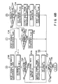
- Subsequently, examples of the determination of the VPS signals will be described with reference to Figs. 8A - 8C.
- As shown in Fig. 8A, when over n no-signals are successively input, VPS signals used for controlling a VTR and a TV are regarded as no-signals. As shown in Fig. 8B, when three signals (program A) are input in succession (including the case where under n no-signals are successively input between the signals (program A), the signals are regarded as VPS signals used for controlling VTR and TV. Further, as shown in Fig. 8C, when a signal for program B is input between signals (program A), the continuity of signals (program A) will be lost. When three signals (program A) are successively input again after the input of the signal for program B, the signals (program A) are regarded as the VPS signals used for controlling VTR and TV.
- Although the preferred embodiments of the present invention have been described and disclosed, it is apparent that other embodiments and modifications of the invention are possible.
- For instance, while in the illustrated preferred embodiments, two memory buffers are used for determining three normal VPS signals of the same program which are successively input, the present invention may be applied to the determination of four or five VPS signals which are successively input. In this case, three or four memory buffers will be needed.
Claims (9)
storing the video program system signal detected from the television signal;
determining whether or not the stored video program system signal is a no-signal;
counting a no-signal count value when the stored video program system signal is the no-signal;
outputting the no-signal when the no-signal count value exceeds a first predetermined count value;
determining whether or not the stored video program system signal is a normal signal;
counting an error count value when different video program system signals are stored;
outputting the no-signal when the error count value exceeds a second predetermined count value; and
outputting the stored video program system signal when the predetermined number of normal signals is continuously stored except for the storage of the predetermined number of no-signals.
input buffer means (11) for storing the video program system signal detected from the television signal;
determining means (21) for determining the video program system signal stored in the input buffer means (11);
memory buffer means (12, 13) for storing the video program system signal stored in the input buffer means (11) in accordance with a determination result obtained by the determining means (21);
error counter means (15) for counting an error count value in accordance with the determination result obtained by the determining means (21); and
no-signal counter means (14) for counting a no-signal count value in accordance with the determination result obtained by the determining means (21).
first determining means (21) for determining whether or not the video program system signal stored in the input buffer means (11) is a no-signal; and second determining means (21) for determining whether or not the video program system signal stored in the input buffer means (11) is a normal signal.
storing means (11) for storing the video program system signal detected from the television signal;
first determining means (21) for determining whether or not the video program system signal stored in the storing means (11) is a no-signal;
no-signal counter means (14) for counting a no-signal count value when the video program system signal stored in the storing means (11) is the no-signal;
first outputting means (21) for outputting the no-signal when the no-signal count value of the no-signal counting means (14) exceeds a first predetermined count value;
second determining means (21) for determining whether or not the video program system signal stored in the storing means (11) is a normal signal;
error counter means (15) for counting an error count value when different video program system signals are stored in the storing means (11);
second outputting means (21) for outputting the no-signal when the error count value of the error counter means (15) exceeds a second predetermined count value; and
third outputting means (21) for outputting the video program system signal stored in the storing means (11) when the predetermined number of normal signals is continuously stored in the storing means (11) except for the storage of the predetermined number of no-signals.
Applications Claiming Priority (2)
| Application Number | Priority Date | Filing Date | Title |
|---|---|---|---|
| JP246034/87 | 1987-09-30 | ||
| JP62246034A JPS6489784A (en) | 1987-09-30 | 1987-09-30 | Video program identifying signal deciding device |
Publications (3)
| Publication Number | Publication Date |
|---|---|
| EP0310046A2 true EP0310046A2 (en) | 1989-04-05 |
| EP0310046A3 EP0310046A3 (en) | 1991-04-24 |
| EP0310046B1 EP0310046B1 (en) | 1995-03-08 |
Family
ID=17142465
Family Applications (1)
| Application Number | Title | Priority Date | Filing Date |
|---|---|---|---|
| EP88116030A Expired - Lifetime EP0310046B1 (en) | 1987-09-30 | 1988-09-28 | Method and system for determining video program system signals |
Country Status (4)
| Country | Link |
|---|---|
| US (1) | US4891703A (en) |
| EP (1) | EP0310046B1 (en) |
| JP (1) | JPS6489784A (en) |
| DE (1) | DE3853247T2 (en) |
Families Citing this family (18)
| Publication number | Priority date | Publication date | Assignee | Title |
|---|---|---|---|---|
| US4965825A (en) | 1981-11-03 | 1990-10-23 | The Personalized Mass Media Corporation | Signal processing apparatus and methods |
| US7831204B1 (en) | 1981-11-03 | 2010-11-09 | Personalized Media Communications, Llc | Signal processing apparatus and methods |
| USRE47642E1 (en) | 1981-11-03 | 2019-10-08 | Personalized Media Communications LLC | Signal processing apparatus and methods |
| US5701593A (en) * | 1989-08-25 | 1997-12-23 | Deutsche Thomson-Brandt Gmbh | Method and means for the transmitter-side controller operation of a receiver-side device |
| NL8902241A (en) * | 1989-09-07 | 1991-04-02 | Philips Nv | DEVICE FOR PROGRAMMING A VIDEO RECORDER, AND A VIDEO RECORDER PROVIDED WITH THE DEVICE. |
| US5469207A (en) * | 1989-12-06 | 1995-11-21 | British Broadcasting Corporation | Method of labelling a broadcast signal including transmitting a sequence of program labels |
| US5003390A (en) * | 1990-03-26 | 1991-03-26 | Pbse Enterprises, Inc. | Search and lock technique for reliable acquisition of data transmitted via television signals |
| JP2830334B2 (en) * | 1990-03-28 | 1998-12-02 | ソニー株式会社 | Material distribution system |
| GB9012005D0 (en) * | 1990-05-30 | 1990-07-18 | British Broadcasting Corp | Broadcast receiver system |
| KR0178536B1 (en) * | 1991-03-11 | 1999-04-15 | 강진구 | Channel selecting method of relative program |
| JP2606477B2 (en) * | 1991-04-17 | 1997-05-07 | 日本ビクター株式会社 | Video signal transceiver |
| US5210611A (en) * | 1991-08-12 | 1993-05-11 | Keen Y. Yee | Automatic tuning radio/TV using filtered seek |
| DE69314224T2 (en) * | 1992-05-19 | 1998-01-29 | Thomson Multimedia Sa | Method and device for device control with data transmission in television lines |
| BE1007077A3 (en) * | 1993-05-13 | 1995-03-07 | Philips Electronics Nv | TRANSMITTING STATION FOR THE TRANSMISSION OF A PLURALITY OF TELEVISION PROGRAMS, AND A RECEIVER FOR RECEIVING THE PROGRAMS. |
| BE1007167A3 (en) * | 1993-05-13 | 1995-04-11 | Philips Electronics Nv | Broadcasting station for broadcasting a plurality of TELEVISION PROGRAMS, AND RECEIVER FOR RECEIVING IT. |
| EP0967801A1 (en) * | 1998-06-26 | 1999-12-29 | Deutsche Thomson-Brandt Gmbh | Method and apparatus for multistandard video data acquisition |
| US7440677B2 (en) * | 2004-12-23 | 2008-10-21 | Ati Technologies Inc. | Detection of copy protection indicators or redistribution control indicators in an analog video signal |
| US20090251610A1 (en) * | 2008-04-08 | 2009-10-08 | Hsin-Chung Wang | Vertical blanking interval slicer and related method |
Citations (6)
| Publication number | Priority date | Publication date | Assignee | Title |
|---|---|---|---|---|
| US4479146A (en) * | 1982-03-08 | 1984-10-23 | Discovision Associates | Vertical code verifier |
| DE3341412C1 (en) * | 1983-11-15 | 1985-05-30 | Institut für Rundfunktechnik GmbH, 8000 München | Method for receiving periodically repeated coded information which is transmitted within a television signal |
| DE3439941C1 (en) * | 1984-11-02 | 1985-08-29 | Institut für Rundfunktechnik GmbH, 8000 München | Method for the reception of periodically repeated coded information which is transmitted within a television signal |
| DE3511737A1 (en) * | 1985-03-30 | 1986-10-09 | Standard Elektrik Lorenz Ag, 7000 Stuttgart | Method for outputting a programme identification data word for evaluation in a receiving set |
| DE3623108C1 (en) * | 1986-07-09 | 1987-10-15 | Inst Rundfunktechnik Gmbh | Method for contribution- or time-controlled recording of television programme contributions |
| EP0133985B1 (en) * | 1983-08-03 | 1989-05-31 | Interessengemeinschaft für Rundfunkschutzrechte GmbH Schutzrechtsverwertung & Co. KG. | Device for automatically switching on and off the recording mode in a video recorder |
Family Cites Families (3)
| Publication number | Priority date | Publication date | Assignee | Title |
|---|---|---|---|---|
| DE3020787A1 (en) * | 1980-05-31 | 1981-12-17 | Blaupunkt-Werke Gmbh, 3200 Hildesheim | METHOD FOR TRANSMITTING ADDITIONAL INFORMATION |
| DE3038088C2 (en) * | 1980-10-09 | 1982-09-09 | Institut für Rundfunktechnik GmbH, 8000 München | Data receiver for a data signal keyed into a video signal |
| US4706121B1 (en) * | 1985-07-12 | 1993-12-14 | Insight Telecast, Inc. | Tv schedule system and process |
-
1987
- 1987-09-30 JP JP62246034A patent/JPS6489784A/en active Pending
-
1988
- 1988-09-22 US US07/247,604 patent/US4891703A/en not_active Expired - Fee Related
- 1988-09-28 EP EP88116030A patent/EP0310046B1/en not_active Expired - Lifetime
- 1988-09-28 DE DE3853247T patent/DE3853247T2/en not_active Expired - Fee Related
Patent Citations (6)
| Publication number | Priority date | Publication date | Assignee | Title |
|---|---|---|---|---|
| US4479146A (en) * | 1982-03-08 | 1984-10-23 | Discovision Associates | Vertical code verifier |
| EP0133985B1 (en) * | 1983-08-03 | 1989-05-31 | Interessengemeinschaft für Rundfunkschutzrechte GmbH Schutzrechtsverwertung & Co. KG. | Device for automatically switching on and off the recording mode in a video recorder |
| DE3341412C1 (en) * | 1983-11-15 | 1985-05-30 | Institut für Rundfunktechnik GmbH, 8000 München | Method for receiving periodically repeated coded information which is transmitted within a television signal |
| DE3439941C1 (en) * | 1984-11-02 | 1985-08-29 | Institut für Rundfunktechnik GmbH, 8000 München | Method for the reception of periodically repeated coded information which is transmitted within a television signal |
| DE3511737A1 (en) * | 1985-03-30 | 1986-10-09 | Standard Elektrik Lorenz Ag, 7000 Stuttgart | Method for outputting a programme identification data word for evaluation in a receiving set |
| DE3623108C1 (en) * | 1986-07-09 | 1987-10-15 | Inst Rundfunktechnik Gmbh | Method for contribution- or time-controlled recording of television programme contributions |
Non-Patent Citations (1)
| Title |
|---|
| NACHRICHTENTECHNISCHE ZEITSCHRIFT N.T.Z., vol. 35, no. 6, June 1982, pages 368-376; H.E. KR]GER: "Das digitale Fernsehkennungssystem ZPS" * |
Also Published As
| Publication number | Publication date |
|---|---|
| EP0310046B1 (en) | 1995-03-08 |
| EP0310046A3 (en) | 1991-04-24 |
| DE3853247T2 (en) | 1995-06-29 |
| JPS6489784A (en) | 1989-04-04 |
| DE3853247D1 (en) | 1995-04-13 |
| US4891703A (en) | 1990-01-02 |
Similar Documents
| Publication | Publication Date | Title |
|---|---|---|
| EP0310046A2 (en) | Method and system for determining video program system signals | |
| JPH08289244A (en) | Method and equipment for television signal sorting | |
| CA1138537A (en) | Synchronizing signal detecting apparatus | |
| US5337157A (en) | Copy guard processing detecting apparatus | |
| US5237319A (en) | Remote control device with learning function | |
| US7697822B2 (en) | Apparatus and method for automatically selecting and recording highlight portions of a broadcast signal | |
| US4991025A (en) | Arrangement for automatically switching a videorecorder on and off in the absence of a code signal but in presence of a FBAS signal | |
| US4656604A (en) | Control circuit with recovery protection | |
| US4159481A (en) | Synchronizing signal selecting circuit | |
| CA1303732C (en) | Apparatus for reserving programs at various recording tape running speeds | |
| US5510849A (en) | Circuit and method for generating caption signal in video signal processing system | |
| KR950013388B1 (en) | Electronic circuit device for electrical code lock | |
| US6784943B1 (en) | Auxiliary digital data extractor in a television | |
| EP0687107B1 (en) | Television receiver incorporating video recording and reproducing apparatus | |
| US4160993A (en) | VIR line recognition system | |
| US5619336A (en) | Recording apparatus and method for video cassette recorder having snow noise removing function | |
| JPS61190755A (en) | Address circuit | |
| US3980958A (en) | Signal seeking tuning system with illegal channel detection means | |
| JPH05500892A (en) | How to label broadcast signals | |
| EP0293492B1 (en) | Tv program recording system | |
| KR100279167B1 (en) | TV line and field detection devices with good noise immunity | |
| GB2186136A (en) | Video recorder | |
| JP3279113B2 (en) | Frequency discrimination method and video projector | |
| JP3138582B2 (en) | Anti-theft viewing device in CATV terminal device | |
| EP0748117A2 (en) | G-code decoder for use with a video tape recorder and method for same |
Legal Events
| Date | Code | Title | Description |
|---|---|---|---|
| PUAI | Public reference made under article 153(3) epc to a published international application that has entered the european phase |
Free format text: ORIGINAL CODE: 0009012 |
|
| 17P | Request for examination filed |
Effective date: 19881025 |
|
| AK | Designated contracting states |
Kind code of ref document: A2 Designated state(s): DE FR GB |
|
| PUAL | Search report despatched |
Free format text: ORIGINAL CODE: 0009013 |
|
| AK | Designated contracting states |
Kind code of ref document: A3 Designated state(s): DE FR GB |
|
| 17Q | First examination report despatched |
Effective date: 19930219 |
|
| GRAA | (expected) grant |
Free format text: ORIGINAL CODE: 0009210 |
|
| AK | Designated contracting states |
Kind code of ref document: B1 Designated state(s): DE FR GB |
|
| REF | Corresponds to: |
Ref document number: 3853247 Country of ref document: DE Date of ref document: 19950413 |
|
| ET | Fr: translation filed | ||
| PLBE | No opposition filed within time limit |
Free format text: ORIGINAL CODE: 0009261 |
|
| STAA | Information on the status of an ep patent application or granted ep patent |
Free format text: STATUS: NO OPPOSITION FILED WITHIN TIME LIMIT |
|
| 26N | No opposition filed | ||
| PGFP | Annual fee paid to national office [announced via postgrant information from national office to epo] |
Ref country code: GB Payment date: 19960919 Year of fee payment: 9 |
|
| PGFP | Annual fee paid to national office [announced via postgrant information from national office to epo] |
Ref country code: DE Payment date: 19961004 Year of fee payment: 9 |
|
| PGFP | Annual fee paid to national office [announced via postgrant information from national office to epo] |
Ref country code: FR Payment date: 19970909 Year of fee payment: 10 |
|
| PG25 | Lapsed in a contracting state [announced via postgrant information from national office to epo] |
Ref country code: GB Free format text: LAPSE BECAUSE OF NON-PAYMENT OF DUE FEES Effective date: 19970928 |
|
| GBPC | Gb: european patent ceased through non-payment of renewal fee |
Effective date: 19970928 |
|
| PG25 | Lapsed in a contracting state [announced via postgrant information from national office to epo] |
Ref country code: DE Free format text: LAPSE BECAUSE OF NON-PAYMENT OF DUE FEES Effective date: 19980603 |
|
| PG25 | Lapsed in a contracting state [announced via postgrant information from national office to epo] |
Ref country code: FR Free format text: LAPSE BECAUSE OF NON-PAYMENT OF DUE FEES Effective date: 19990531 |
|
| REG | Reference to a national code |
Ref country code: FR Ref legal event code: ST |