US10717571B1 - Clam shell cover cap and method of use - Google Patents
Clam shell cover cap and method of use Download PDFInfo
- Publication number
- US10717571B1 US10717571B1 US16/294,869 US201916294869A US10717571B1 US 10717571 B1 US10717571 B1 US 10717571B1 US 201916294869 A US201916294869 A US 201916294869A US 10717571 B1 US10717571 B1 US 10717571B1
- Authority
- US
- United States
- Prior art keywords
- piece housing
- wheel
- wheels
- container
- unlock code
- Prior art date
- Legal status (The legal status is an assumption and is not a legal conclusion. Google has not performed a legal analysis and makes no representation as to the accuracy of the status listed.)
- Active
Links
- 238000000034 method Methods 0.000 title claims description 22
- 239000003814 drug Substances 0.000 claims abstract description 36
- 229940079593 drug Drugs 0.000 abstract description 27
- 238000003860 storage Methods 0.000 description 11
- 238000005516 engineering process Methods 0.000 description 5
- 230000006870 function Effects 0.000 description 5
- 238000002483 medication Methods 0.000 description 5
- 238000004891 communication Methods 0.000 description 4
- 239000000463 material Substances 0.000 description 4
- 239000004033 plastic Substances 0.000 description 4
- 238000013461 design Methods 0.000 description 3
- 238000012986 modification Methods 0.000 description 3
- 230000004048 modification Effects 0.000 description 3
- 230000008569 process Effects 0.000 description 3
- 238000012545 processing Methods 0.000 description 3
- 239000004065 semiconductor Substances 0.000 description 3
- 238000003491 array Methods 0.000 description 2
- 238000010586 diagram Methods 0.000 description 2
- 239000002184 metal Substances 0.000 description 2
- 229910044991 metal oxide Inorganic materials 0.000 description 2
- 150000004706 metal oxides Chemical class 0.000 description 2
- 230000003287 optical effect Effects 0.000 description 2
- 239000004743 Polypropylene Substances 0.000 description 1
- XUIMIQQOPSSXEZ-UHFFFAOYSA-N Silicon Chemical compound [Si] XUIMIQQOPSSXEZ-UHFFFAOYSA-N 0.000 description 1
- 230000003542 behavioural effect Effects 0.000 description 1
- 230000008901 benefit Effects 0.000 description 1
- 230000005540 biological transmission Effects 0.000 description 1
- 230000000295 complement effect Effects 0.000 description 1
- 229920000547 conjugated polymer Polymers 0.000 description 1
- 230000003247 decreasing effect Effects 0.000 description 1
- 238000011982 device technology Methods 0.000 description 1
- 230000000694 effects Effects 0.000 description 1
- 238000001125 extrusion Methods 0.000 description 1
- 230000005669 field effect Effects 0.000 description 1
- 230000008676 import Effects 0.000 description 1
- 230000014759 maintenance of location Effects 0.000 description 1
- 238000004519 manufacturing process Methods 0.000 description 1
- 230000005055 memory storage Effects 0.000 description 1
- 238000000465 moulding Methods 0.000 description 1
- 230000001537 neural effect Effects 0.000 description 1
- -1 poly propylene Polymers 0.000 description 1
- 229920000642 polymer Polymers 0.000 description 1
- 229920001155 polypropylene Polymers 0.000 description 1
- QQONPFPTGQHPMA-UHFFFAOYSA-N propylene Natural products CC=C QQONPFPTGQHPMA-UHFFFAOYSA-N 0.000 description 1
- 125000004805 propylene group Chemical group [H]C([H])([H])C([H])([*:1])C([H])([H])[*:2] 0.000 description 1
- 238000004549 pulsed laser deposition Methods 0.000 description 1
- 229910052710 silicon Inorganic materials 0.000 description 1
- 239000010703 silicon Substances 0.000 description 1
- 238000009987 spinning Methods 0.000 description 1
- 238000012546 transfer Methods 0.000 description 1
Images


Classifications
-
- A—HUMAN NECESSITIES
- A61—MEDICAL OR VETERINARY SCIENCE; HYGIENE
- A61J—CONTAINERS SPECIALLY ADAPTED FOR MEDICAL OR PHARMACEUTICAL PURPOSES; DEVICES OR METHODS SPECIALLY ADAPTED FOR BRINGING PHARMACEUTICAL PRODUCTS INTO PARTICULAR PHYSICAL OR ADMINISTERING FORMS; DEVICES FOR ADMINISTERING FOOD OR MEDICINES ORALLY; BABY COMFORTERS; DEVICES FOR RECEIVING SPITTLE
- A61J1/00—Containers specially adapted for medical or pharmaceutical purposes
- A61J1/14—Details; Accessories therefor
- A61J1/1437—Locking means requiring key or combination to open the container
-
- A—HUMAN NECESSITIES
- A61—MEDICAL OR VETERINARY SCIENCE; HYGIENE
- A61J—CONTAINERS SPECIALLY ADAPTED FOR MEDICAL OR PHARMACEUTICAL PURPOSES; DEVICES OR METHODS SPECIALLY ADAPTED FOR BRINGING PHARMACEUTICAL PRODUCTS INTO PARTICULAR PHYSICAL OR ADMINISTERING FORMS; DEVICES FOR ADMINISTERING FOOD OR MEDICINES ORALLY; BABY COMFORTERS; DEVICES FOR RECEIVING SPITTLE
- A61J1/00—Containers specially adapted for medical or pharmaceutical purposes
- A61J1/03—Containers specially adapted for medical or pharmaceutical purposes for pills or tablets
-
- A—HUMAN NECESSITIES
- A61—MEDICAL OR VETERINARY SCIENCE; HYGIENE
- A61J—CONTAINERS SPECIALLY ADAPTED FOR MEDICAL OR PHARMACEUTICAL PURPOSES; DEVICES OR METHODS SPECIALLY ADAPTED FOR BRINGING PHARMACEUTICAL PRODUCTS INTO PARTICULAR PHYSICAL OR ADMINISTERING FORMS; DEVICES FOR ADMINISTERING FOOD OR MEDICINES ORALLY; BABY COMFORTERS; DEVICES FOR RECEIVING SPITTLE
- A61J7/00—Devices for administering medicines orally, e.g. spoons; Pill counting devices; Arrangements for time indication or reminder for taking medicine
- A61J7/0076—Medicament distribution means
-
- B—PERFORMING OPERATIONS; TRANSPORTING
- B65—CONVEYING; PACKING; STORING; HANDLING THIN OR FILAMENTARY MATERIAL
- B65D—CONTAINERS FOR STORAGE OR TRANSPORT OF ARTICLES OR MATERIALS, e.g. BAGS, BARRELS, BOTTLES, BOXES, CANS, CARTONS, CRATES, DRUMS, JARS, TANKS, HOPPERS, FORWARDING CONTAINERS; ACCESSORIES, CLOSURES, OR FITTINGS THEREFOR; PACKAGING ELEMENTS; PACKAGES
- B65D55/00—Accessories for container closures not otherwise provided for
- B65D55/02—Locking devices; Means for discouraging or indicating unauthorised opening or removal of closure
- B65D55/14—Applications of locks, e.g. of permutation or key-controlled locks
- B65D55/145—Applications of locks, e.g. of permutation or key-controlled locks of permutation locks
-
- A—HUMAN NECESSITIES
- A61—MEDICAL OR VETERINARY SCIENCE; HYGIENE
- A61J—CONTAINERS SPECIALLY ADAPTED FOR MEDICAL OR PHARMACEUTICAL PURPOSES; DEVICES OR METHODS SPECIALLY ADAPTED FOR BRINGING PHARMACEUTICAL PRODUCTS INTO PARTICULAR PHYSICAL OR ADMINISTERING FORMS; DEVICES FOR ADMINISTERING FOOD OR MEDICINES ORALLY; BABY COMFORTERS; DEVICES FOR RECEIVING SPITTLE
- A61J1/00—Containers specially adapted for medical or pharmaceutical purposes
- A61J1/14—Details; Accessories therefor
- A61J1/1412—Containers with closing means, e.g. caps
Definitions
- FIG. 1 is a view of a clam shell cover cap device in the closed/down position with the correct combination set.
- FIGS. 2A and 2B are a sectional view of the clam shell cover cap device shown in FIG. 1 in the unlocked position and a section view of the clam shell cover cap device in the locked position.
- FIG. 4 is a view of the clam shell cover cap device in the open/up position with the medication bottle exposed, set in the device housing.
- FIG. 5 is a view of the clam shell cover cap device in the open/up position with the medication bottle removed from the device housing.
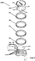
- FIG. 7 is an exploded assembly diagram of the clam shell cover cap device.
- FIGS. 8A-8F are views illustrating the wheel carriage of the clam shell cover cap device.
- FIGS. 9A-9D are views illustrating the non-resettable number wheel, shown with the example number zero.
- FIGS. 11A-11D are view of the clam shell cover cap device housing.
- the disclosure is particularly applicable to a clam shell cover cap that may be placed over a closed vial, bottle or other container of contents (such as the medicine bottles shown in FIG. 6 that surrounds the closed container to prevent an unauthorized user from accessing the contents of the container and it is in this context that the disclosure will be described.
- the clam shell cover cap may be used for various differently shaped and sized containers with caps that are closed and may further be adapted to be used with various differently shaped containers that are open.
- the clam shell cover cap device may also be used with other container of various shapes and sizes.
- the disclosure relates to a clam shell cover cap device 1000 that may be fitted over a container 1002 (with or without a cap) and thus prevent unauthorized user (a person that does not know the combination) to access the contents of the container.
- FIG. 1 , FIG. 2 , FIG. 3 , and FIG. 4 show how the locking cap device 1000 functions when the device is unlocked or locked.
- the locking cap 1000 may be set to a locking combination once (by a user or a pharmacy worker or a hospital worker) but cannot be reset to a different locking combination as described below in more detail.
- the locking cap 1000 is set to “0000”, but could also be set to other combinations, such as 1012 or 0102 , as shown in FIG. 1 .
- the wheels 46 a - 46 d of the locking cap 100 may display the numbers as shown in FIG. 1 , but the wheels may also display other alphanumeric characters or other symbols that form the combination to unlock the locking cap 1000 .
- the combination for the locking cap 1000 may be provided to the user (when the user does not set the combination, on a sticker or piece of paper or other indicator 36 , 8 , 18 as shown in FIG. 1 .
- the portions of the clam shell cover cap device 1000 may be made out of a poly propylene plastic with properties where the plastic is rigid where thick and can hinge many times where thin without breaking. Other materials can also be used, but the properties of propylene make are good for there flexible and rigid qualities.
- the clam shell cover cap device 1000 may further comprise a cap portion 1008 that is described below in more detail with reference to FIGS. 8A-8F .
- the locking portion 1006 may further comprising one or more wheels 46 a - 46 d , four being shown in the example in the Figures, rotate between an unlocking combination as shown in FIG. 1 and a plurality of locking combinations (being all of the other possible combinations of the symbols of the one or more wheels except for the unlocking combination).
- Each wheel may have one or more symbols (with numbers in the example shown) and the symbols on each wheel may be rotated around to arrive at the unlocking combination as shown in FIG. 1 .
- a user of the device 100 may rotate any one or more of the wheels so that the symbols shown adjacent the indicators 61 , 62 (such as 1234) no longer are the unlocking combination and the device 1000 is locked onto the container 1002 until the locking combination is again set.
- the indicators 61 , 62 that indicate the location at which the unlocking code will unlock the clam shell cap cover device 1000 may be located, as shown on FIG. 1 , on the cap portion 1008 and the housing 1004 , but may also be located elsewhere.
- Each indicator 61 , 62 may be a physical element, may be a symbol indented into the material or painted. While the indicators in FIG. 1 are an arrow 61 and a dot 62 , each indicator may be any type of symbol that can indicate to a user a location for the unlocking code so that each indicator may be a star, the dot, the arrow, two arrows, etc.
- the container 1002 may house/store contents that may be locked or unlocked using the clam shell cap cover device 1000 to prevent unauthorized access to the contents.
- the contents may be a medication or prescription and the container 1002 may be a medication bottle that a patient may pick up from a pharmacy.
- an employee of the pharmacy may select an unlock code (as described below) and provide the unlock code to the patient or the pharmacy may retrieve the clam shell cap cover device 1000 that has already has a set unlock code that is provided to the patient.
- FIGS. 2A and 2B are a sectional view of the clam shell cover cap device shown in FIG. 1A in the unlocked position and a sectional view of the clam shell cover cap device in the locked position.
- each wheel 46 A- 46 D is a ring that rotates about a wheel center post 1010 of the housing 1004 .
- the wheel center post 1010 has one or more tabs 1010 A wherein each tab 1010 A interacts with each wheel 46 A- 46 D.
- Each wheel 46 A- 46 D has a cutout region 47 in the ring as shown.
- the tabs 1010 A and the cutout regions 47 are vertically positioned adjacent and aligned with each other so that the clam shell cover cap device can be removed from the container 1002 .
- FIG. 2B when the clam shell cover cap device 1000 is locked which means that a symbol on at least one wheel is no longer the unlocking combination, such as the wheels showing 0001 or 1234, etc. adjacent the indicators 61 , 62 )
- the tabs 1010 A is not aligned with at least one of the cutout regions 47 of the wheel so that the clam shell cover cap device 1000 cannot be removed from the container 1002 .
- FIG. 3 is a view of the clam shell cover cap device 1000 in the closed/up position with the correct combination set.
- the housing 1004 and the wheel assembly may be pulled upward since the tabs 1010 A and cutout regions 47 are aligned.
- the housing 1004 has a living hinge 66 on the housing which splits the housing into two sides as shown in FIG. 4 once the housing 1004 is opened.
- there is a gap and the housing has a ridge portion 80 that is free so that the living hinge 66 can be opened.
- the ridge at position 70 on FIG. 3 when closed/down, prevents the hinge from being opened.
- FIG. 4 is a view of the clam shell cover cap device 1000 in the open/up position with the medication bottle exposed, set in the device housing 1004 with the wheel carriage 1006 and number wheels 46 A- 46 D are in the up position exposing an existing medication bottle 1002 A that has an existing medication closure/cap 118 and FIG. 5 shows the medication bottle 1002 A and its cap 118 being removed from the clam shell cover cap device 1000 .
- the up position also note that the lowest tab 1008 A is exposed.
- a first side of the housing 84 separates from a second side of the housing 86 at the hinge 66 in a clam shell fashion.
- the clam shell cover cap device 1000 is a modular design wherein the housing carriage 1006 , the housing 1004 and the wheels 46 A- 46 D do not come apart from the housing after assembly. When open the existing medication bottle 120 and existing medication bottle closure 118 can be removed from the modular device shown in FIG. 5 .
- the internal structure of the housing 1004 may have internal structures that may be adjusted to accommodate different containers and bottles.
- the existing medication bottle 1002 A and existing closure 118 fit inside the housing 1004 in a cavity 400 within the housing 1004 formed when the two pieces of the housing are closed.
- the bottle/container closure 118 may have a lip 139 that permits the clam shell cover cap device 1000 to securely lock to the medication bottle or vial.
- a lip retention ring 124 , 120 in the housing 1004 and the inside shape of the cavity 400 can be made to fit different bottles and vials shown in FIG. 6 .
- FIG. 6 shows examples of two existing medication bottles 142 , 154 with different style closures, both of which may fit into the clam shell cover cap device 1000 .
- Each bottle 142 , 154 has a lip 146 and 152 in order to be secured in the device.
- Some odd shapes 144 can be adjusted for within the housing 1000 design and the cavity 400 design.
- various different cavity 400 shapes and sizes may be manufactured for different sized or shaped bottles and caps.
- the clam shell cover cap device 1000 may be used for other containers or for a medication bottle without a cap and then the size and shape of the cavity 400 may be adjusted as needed.
- the wheel carriage arms 156 - 162 are slid onto the housing 1004 , past a one way catch 282 and into position surrounding the wheel center post 1010 .
- the one way catch 282 prevents the wheel carriage arms 156 - 162 and cap 1008 from slipping off of the housing 1004 .
- the wheel carriage arms 156 - 162 has some up and down freedom when unlocked to secure a top catch 264 on the small side of the housing.
- a bottle 1002 can be placed inside the cavity 400 of the bell housing, two piece housing is closed in a clam shell manner. The wheels 46 A- 46 D and the cap portion 1008 may then be moved downward to close the clam shell cover cap device 1000 .
- FIGS. 8A-8F are views illustrating the wheel carriage of the clam shell cover cap device with the cap portion 108 and the wheel carriage arms 156 - 162 .
- the wheel carriage holds the wheels between points 168 and 164 of the four carriage arms 156 , 158 , 160 , 162 .
- the carriage arms 156 - 162 are flexible and when assembled they bend inward towards the center thus decreasing the diameter and allows for the one or more preset wheel 46 A- 46 D to slide over. From the back/side view 166 , the carriage arms 202 and 204 along with the other two arms are pushed together to assemble the number wheels onto the wheel carriage.
- each arm has a retaining feature 170 that retains the wheels 46 A- 46 D on the wheel carriage.
- FIGS. 9A-9D are views illustrating the non-resettable number wheel 800 , shown with the example number zero.
- the cut-out region/notch 47 may be adjacent the “0” symbol on the wheel since “0” represents the unlocked position of the exemplary number wheel shown in FIGS. 9A-9D . If the wheel's unlock symbol was “2”, then the cutout region/notch 47 would be adjacent to the “2” symbol.
- Each wheel may further comprise a number, such as ten, of security nubs 206 . If pressure is forced in the wrong direction, these nubs 206 will bind on the housing tabs 1010 A and the wheels will have trouble spinning around the housing.
- each symbol on a wheel may be molded sticking out from the surface of the wheel as shown in FIGS. 9A-9D , but can also be molded inward or printed onto a flat surface of a wheel.
- FIG. 10 shows each non-resettable wheel that may be provided to an authorized user who sets the unlock code for the clam shell cover cap device 1000 .
- the symbols used are “0” to “9” and the combinations, including the unlock combination, are number combinations. If other symbols are being used for the clam shell cover cap device 1000 , then the wheels will look differently since the symbols on the outside of the wheel will be different.
- each wheel shown has its own unlocking symbol, “0” to “9” as can be seen by the cutout region adjacent each unlocking symbol.
- each wheel is molded separately.
- this is used to determine the assembly of the combination may be provided when the non-resettable unlock code is set by the manufacturer.
- the manufacturer or the authorized user selects the wheels for the selected unlock code.
- FIGS. 11A-11D are view of the clam shell cover cap device housing 1004 with the center post 1010 and the living hinge 66 between the two pieces 84 , 86 of the two piece housing.
- the center post may have one or more tabs/locking teeth that keep the clam shell cover cap device 1000 locked until the unlock code is aligned with the indicators.
- center post 1010 may have a first tab/locking tooth 1102 , a second tab/locking tooth 1104 , a third tab/locking tooth 1106 and a fourth tab/locking tooth 1108 that are fixed by the center post 1010 to be in vertical alignment with each wheel when the one or more wheels are installed to set the unlock code.
- the center post 1010 may have two rows of four locking teeth for added security.
- a top round portion 314 of the smaller side 84 fits into the lower cavity of the larger side 86 into the position seen at 258 and 256 .
- the top portion 314 of the smaller side 84 is the bottom of the cylinder that the wheel carriage 1008 slides over when the device is assembled.
- the smaller side 84 of the housing 1004 cannot be opened and this locks the device 1000 onto the top of an existing medication bottle and closure 1002 .
- the housing teeth 1102 - 1108 hold the wheel carriage 1008 and wheels 46 A- 46 D in place.
- the wheel carriage 1008 with the wheels 46 A- 46 D can move up, freeing the smaller side 84 of the housing 1004 to hinge open which releases the existing medication bottle 1002 from the device 1000 .
- the device 1000 is modular once assembled and there are two one way catches 286 and 290 on the housing 10004 (see FIG. 11A ) which fit into the wheel carriage 1008 .
- Two of the carriage arms of the wheel carriage 1008 may include a cut-out 178 which slides past the one way catches 286 and 290 locking the carriage 1008 onto the housing 1004 and making the device 1000 modular once assembled. More specifically, once past the one way catch feature 286 , 290 during assembly, the wheel carriage 1008 will not come off the housing 1004 through normal use.
- the shape and size of the housing cavity/bell 332 and 342 can be adjusted based on the type of container 1002 being secured.
- the existing bottle 142 FIG. 6
- the existing bottle 142 has an extrusion which is not round and this feature is compensated for in the bell housing. If the existing bottle was simply round, the round surface of the bell part of the housing would be reflected onto the larger side of the housing 1004 .
- There are structures 272 , 274 , 276 , 278 , 268 , 306 , 298 292 , 294 , 296 built into the bell housing to fit specific bottles/containers 1002 and these are support structures to hold containers, such as existing medication bottles, in place correctly.
- system and method disclosed herein may be implemented via one or more components, systems, servers, appliances, other subcomponents, or distributed between such elements.
- systems may include an/or involve, inter alia, components such as software modules, general-purpose CPU, RAM, etc. found in general-purpose computers.
- components such as software modules, general-purpose CPU, RAM, etc. found in general-purpose computers.
- a server may include or involve components such as CPU, RAM, etc., such as those found in general-purpose computers.
- exemplary computing systems, environments, and/or configurations may include, but are not limited to: software or other components within or embodied on personal computers, servers or server computing devices such as routing/connectivity components, hand-held or laptop devices, multiprocessor systems, microprocessor-based systems, set top boxes, consumer electronic devices, network PCs, other existing computer platforms, distributed computing environments that include one or more of the above systems or devices, etc.
- aspects of the system and method may be achieved via or performed by logic and/or logic instructions including program modules, executed in association with such components or circuitry, for example.
- program modules may include routines, programs, objects, components, data structures, etc. that perform particular tasks or implement particular instructions herein.
- the inventions may also be practiced in the context of distributed software, computer, or circuit settings where circuitry is connected via communication buses, circuitry or links. In distributed settings, control/instructions may occur from both local and remote computer storage media including memory storage devices.
- Computer readable media can be any available media that is resident on, associable with, or can be accessed by such circuits and/or computing components.
- Computer readable media may comprise computer storage media and communication media.
- Computer storage media includes volatile and nonvolatile, removable and non-removable media implemented in any method or technology for storage of information such as computer readable instructions, data structures, program modules or other data.
- the terms component, module, device, etc. may refer to any type of logical or functional software elements, circuits, blocks and/or processes that may be implemented in a variety of ways.
- the functions of various circuits and/or blocks can be combined with one another into any other number of modules.
- Each module may even be implemented as a software program stored on a tangible memory (e.g., random access memory, read only memory, CD-ROM memory, hard disk drive, etc.) to be read by a central processing unit to implement the functions of the innovations herein.
- the modules can comprise programming instructions transmitted to a general purpose computer or to processing/graphics hardware via a transmission carrier wave.
- the modules can be implemented as hardware logic circuitry implementing the functions encompassed by the innovations herein.
- the modules can be implemented using special purpose instructions (SIMD instructions), field programmable logic arrays or any mix thereof which provides the desired level performance and cost.
- SIMD instructions special purpose instructions
- features consistent with the disclosure may be implemented via computer-hardware, software and/or firmware.
- the systems and methods disclosed herein may be embodied in various forms including, for example, a data processor, such as a computer that also includes a database, digital electronic circuitry, firmware, software, or in combinations of them.
- a data processor such as a computer that also includes a database
- digital electronic circuitry such as a computer
- firmware such as a firmware
- software such as a computer
- the systems and methods disclosed herein may be implemented with any combination of hardware, software and/or firmware.
- the above-noted features and other aspects and principles of the innovations herein may be implemented in various environments.
- Such environments and related applications may be specially constructed for performing the various routines, processes and/or operations according to the invention or they may include a general-purpose computer or computing platform selectively activated or reconfigured by code to provide the necessary functionality.
- the processes disclosed herein are not inherently related to any particular computer, network, architecture, environment, or other apparatus, and may be implemented by a suitable combination of hardware, software, and/or firmware.
- various general-purpose machines may be used with programs written in accordance with teachings of the invention, or it may be more convenient to construct a specialized apparatus or system to perform the required methods and techniques.
- aspects of the method and system described herein, such as the logic may also be implemented as functionality programmed into any of a variety of circuitry, including programmable logic devices (“PLDs”), such as field programmable gate arrays (“FPGAs”), programmable array logic (“PAL”) devices, electrically programmable logic and memory devices and standard cell-based devices, as well as application specific integrated circuits.
- PLDs programmable logic devices
- FPGAs field programmable gate arrays
- PAL programmable array logic
- Some other possibilities for implementing aspects include: memory devices, microcontrollers with memory (such as EEPROM), embedded microprocessors, firmware, software, etc.
- aspects may be embodied in microprocessors having software-based circuit emulation, discrete logic (sequential and combinatorial), custom devices, fuzzy (neural) logic, quantum devices, and hybrids of any of the above device types.
- the underlying device technologies may be provided in a variety of component types, e.g., metal-oxide semiconductor field-effect transistor (“MOSFET”) technologies like complementary metal-oxide semiconductor (“CMOS”), bipolar technologies like emitter-coupled logic (“ECL”), polymer technologies (e.g., silicon-conjugated polymer and metal-conjugated polymer-metal structures), mixed analog and digital, and so on.
- MOSFET metal-oxide semiconductor field-effect transistor
- CMOS complementary metal-oxide semiconductor
- ECL emitter-coupled logic
- polymer technologies e.g., silicon-conjugated polymer and metal-conjugated polymer-metal structures
- mixed analog and digital and so on.
- the words “comprise,” “comprising,” and the like are to be construed in an inclusive sense as opposed to an exclusive or exhaustive sense; that is to say, in a sense of “including, but not limited to.” Words using the singular or plural number also include the plural or singular number respectively. Additionally, the words “herein,” “hereunder,” “above,” “below,” and words of similar import refer to this application as a whole and not to any particular portions of this application. When the word “or” is used in reference to a list of two or more items, that word covers all of the following interpretations of the word: any of the items in the list, all of the items in the list and any combination of the items in the list.
Abstract
A clam shell cover cap device is a lockable closure which fits over existing medication vials used in the pharmacy and medical industries. It comes preset, with a random combination. The combination is marked with an indicator sticker. The clam Shell Cover Cap may be used to lock a vial.
Description
This application claims the benefit under 35 USC 119(e) and 120 to U.S. Provisional Patent Application Ser. No. 62/639,162, filed on Mar. 6, 2018 that is incorporated herein by reference.
The disclosure relates to a closure lock, in particular to a lock for existing medication vials and bottles.
There is need for additional safety and security for some medications. The current vials and closures used for medication storage are not safe enough. Child resistant closures are the only safety measures on some medications. While these may keep some small children from getting into medications, they have little to no effect at keeping a teenager or other unauthorized user out of a medication. This device is designed to limit access to only the person who knows the combination. It surrounds the closure on the vials currently used in the medical field. It allows for greater safety and security of medications through easily locking them up.
The disclosure is particularly applicable to a clam shell cover cap that may be placed over a closed vial, bottle or other container of contents (such as the medicine bottles shown in FIG. 6 that surrounds the closed container to prevent an unauthorized user from accessing the contents of the container and it is in this context that the disclosure will be described. It will be appreciated, however, that the clam shell cover cap may be used for various differently shaped and sized containers with caps that are closed and may further be adapted to be used with various differently shaped containers that are open. The clam shell cover cap device may also be used with other container of various shapes and sizes.
The disclosure relates to a clam shell cover cap device 1000 that may be fitted over a container 1002 (with or without a cap) and thus prevent unauthorized user (a person that does not know the combination) to access the contents of the container. FIG. 1 , FIG. 2 , FIG. 3 , and FIG. 4 show how the locking cap device 1000 functions when the device is unlocked or locked. The locking cap 1000 may be set to a locking combination once (by a user or a pharmacy worker or a hospital worker) but cannot be reset to a different locking combination as described below in more detail. In the example shown in FIG. 1 , the locking cap 1000 is set to “0000”, but could also be set to other combinations, such as 1012 or 0102, as shown in FIG. 1 . Note that the wheels 46 a-46 d of the locking cap 100 may display the numbers as shown in FIG. 1 , but the wheels may also display other alphanumeric characters or other symbols that form the combination to unlock the locking cap 1000. In one embodiment, the combination for the locking cap 1000 may be provided to the user (when the user does not set the combination, on a sticker or piece of paper or other indicator 36, 8, 18 as shown in FIG. 1 .
The indicators 61, 62 that indicate the location at which the unlocking code will unlock the clam shell cap cover device 1000 may be located, as shown on FIG. 1 , on the cap portion 1008 and the housing 1004, but may also be located elsewhere. Each indicator 61, 62 may be a physical element, may be a symbol indented into the material or painted. While the indicators in FIG. 1 are an arrow 61 and a dot 62, each indicator may be any type of symbol that can indicate to a user a location for the unlocking code so that each indicator may be a star, the dot, the arrow, two arrows, etc.
The container 1002 may house/store contents that may be locked or unlocked using the clam shell cap cover device 1000 to prevent unauthorized access to the contents. In one embodiment, the contents may be a medication or prescription and the container 1002 may be a medication bottle that a patient may pick up from a pharmacy. In operation, an employee of the pharmacy may select an unlock code (as described below) and provide the unlock code to the patient or the pharmacy may retrieve the clam shell cap cover device 1000 that has already has a set unlock code that is provided to the patient.
While the combination shown in FIG. 1 has 4 symbols (due to the 4 wheels), the clam shell cover cap device 1000 may have any number of wheels and thus number of combinations. Furthermore, while the symbols in FIG. 1 are numbers, the symbols on each wheel may be alphanumeric characters or any other symbols that may be used for the combination. In one embodiment, the unlock combination is not resettable by the patient or any party, but may be set at the manufacturer or at the pharmacy as described above. In one embodiment, the unlock combination is set be selecting the one or more wheels 46A-46D as described below in more detail.
As shown in FIG. 4 , the existing medication bottle 1002A and existing closure 118 fit inside the housing 1004 in a cavity 400 within the housing 1004 formed when the two pieces of the housing are closed. There are different shapes and sizes of the cavity 400 to accommodate different bottles/containers and different closures and closure sizes. The bottle/container closure 118 may have a lip 139 that permits the clam shell cover cap device 1000 to securely lock to the medication bottle or vial. A lip retention ring 124, 120 in the housing 1004 and the inside shape of the cavity 400 can be made to fit different bottles and vials shown in FIG. 6 .
Once the one-time unlock code is selected and the appropriate wheels selected, the one or more wheels slide over and onto the wheel carriage arms 156-162 and are held on the arms by a ledge region 170 at a bottom of each arm. Note that the order in which the wheels are slid onto the arms 156-162 is important since the order sets the unlock code. For example, if the wheels are “1”, “2”, “3” and “4”, the order of the wheels can set the unlock code to 1234, 4321, 2341, etc.
Next the wheel carriage arms 156-162 are slid onto the housing 1004, past a one way catch 282 and into position surrounding the wheel center post 1010. The one way catch 282 prevents the wheel carriage arms 156-162 and cap 1008 from slipping off of the housing 1004. The wheel carriage arms 156-162 has some up and down freedom when unlocked to secure a top catch 264 on the small side of the housing. When in use, a bottle 1002 can be placed inside the cavity 400 of the bell housing, two piece housing is closed in a clam shell manner. The wheels 46A-46D and the cap portion 1008 may then be moved downward to close the clam shell cover cap device 1000. The user may then rotate the wheels so that the unlock combination is no longer aligned with the indicators that locks the clam shell cover cap device 1000 onto the container 1002 keeping the contents of the container, such as medications, safe and secure. To open the clam shell cover cap device 1000, the user rotates the wheels until the unlock code is aligned with the indicators 61, 62 so that the cap portion 1008 can be move vertically upwards away from the container so that the contained can be removed from the clam shell cover cap device 1000.
When closed together the top portion 314 of the smaller side 84 is the bottom of the cylinder that the wheel carriage 1008 slides over when the device is assembled. When the wheel carriage 1008 slides into the downward position, the smaller side 84 of the housing 1004 cannot be opened and this locks the device 1000 onto the top of an existing medication bottle and closure 1002. When at least one wheel is rotated from the unlocked position to a locked position, the housing teeth 1102-1108 hold the wheel carriage 1008 and wheels 46A-46D in place.
With the unlock code combination aligned with the indicators 61, 62, the wheel carriage 1008 with the wheels 46A-46D can move up, freeing the smaller side 84 of the housing 1004 to hinge open which releases the existing medication bottle 1002 from the device 1000. The device 1000 is modular once assembled and there are two one way catches 286 and 290 on the housing 10004 (see FIG. 11A ) which fit into the wheel carriage 1008. Two of the carriage arms of the wheel carriage 1008 may include a cut-out 178 which slides past the one way catches 286 and 290 locking the carriage 1008 onto the housing 1004 and making the device 1000 modular once assembled. More specifically, once past the one way catch feature 286, 290 during assembly, the wheel carriage 1008 will not come off the housing 1004 through normal use.
The shape and size of the housing cavity/ bell 332 and 342 can be adjusted based on the type of container 1002 being secured. For example, the existing bottle 142 (FIG. 6 ) has an extrusion which is not round and this feature is compensated for in the bell housing. If the existing bottle was simply round, the round surface of the bell part of the housing would be reflected onto the larger side of the housing 1004. There are structures 272, 274, 276, 278, 268, 306, 298 292, 294, 296 built into the bell housing to fit specific bottles/containers 1002 and these are support structures to hold containers, such as existing medication bottles, in place correctly.
The foregoing description, for purpose of explanation, has been described with reference to specific embodiments. However, the illustrative discussions above are not intended to be exhaustive or to limit the disclosure to the precise forms disclosed. Many modifications and variations are possible in view of the above teachings. The embodiments were chosen and described in order to best explain the principles of the disclosure and its practical applications, to thereby enable others skilled in the art to best utilize the disclosure and various embodiments with various modifications as are suited to the particular use contemplated.
The system and method disclosed herein may be implemented via one or more components, systems, servers, appliances, other subcomponents, or distributed between such elements. When implemented as a system, such systems may include an/or involve, inter alia, components such as software modules, general-purpose CPU, RAM, etc. found in general-purpose computers. In implementations where the innovations reside on a server, such a server may include or involve components such as CPU, RAM, etc., such as those found in general-purpose computers.
Additionally, the system and method herein may be achieved via implementations with disparate or entirely different software, hardware and/or firmware components, beyond that set forth above. With regard to such other components (e.g., software, processing components, etc.) and/or computer-readable media associated with or embodying the present inventions, for example, aspects of the innovations herein may be implemented consistent with numerous general purpose or special purpose computing systems or configurations. Various exemplary computing systems, environments, and/or configurations that may be suitable for use with the innovations herein may include, but are not limited to: software or other components within or embodied on personal computers, servers or server computing devices such as routing/connectivity components, hand-held or laptop devices, multiprocessor systems, microprocessor-based systems, set top boxes, consumer electronic devices, network PCs, other existing computer platforms, distributed computing environments that include one or more of the above systems or devices, etc.
In some instances, aspects of the system and method may be achieved via or performed by logic and/or logic instructions including program modules, executed in association with such components or circuitry, for example. In general, program modules may include routines, programs, objects, components, data structures, etc. that perform particular tasks or implement particular instructions herein. The inventions may also be practiced in the context of distributed software, computer, or circuit settings where circuitry is connected via communication buses, circuitry or links. In distributed settings, control/instructions may occur from both local and remote computer storage media including memory storage devices.
The software, circuitry and components herein may also include and/or utilize one or more type of computer readable media. Computer readable media can be any available media that is resident on, associable with, or can be accessed by such circuits and/or computing components. By way of example, and not limitation, computer readable media may comprise computer storage media and communication media. Computer storage media includes volatile and nonvolatile, removable and non-removable media implemented in any method or technology for storage of information such as computer readable instructions, data structures, program modules or other data. Computer storage media includes, but is not limited to, RAM, ROM, EEPROM, flash memory or other memory technology, CD-ROM, digital versatile disks (DVD) or other optical storage, magnetic tape, magnetic disk storage or other magnetic storage devices, or any other medium which can be used to store the desired information and can accessed by computing component. Communication media may comprise computer readable instructions, data structures, program modules and/or other components. Further, communication media may include wired media such as a wired network or direct-wired connection, however no media of any such type herein includes transitory media. Combinations of the any of the above are also included within the scope of computer readable media.
In the present description, the terms component, module, device, etc. may refer to any type of logical or functional software elements, circuits, blocks and/or processes that may be implemented in a variety of ways. For example, the functions of various circuits and/or blocks can be combined with one another into any other number of modules. Each module may even be implemented as a software program stored on a tangible memory (e.g., random access memory, read only memory, CD-ROM memory, hard disk drive, etc.) to be read by a central processing unit to implement the functions of the innovations herein. Or, the modules can comprise programming instructions transmitted to a general purpose computer or to processing/graphics hardware via a transmission carrier wave. Also, the modules can be implemented as hardware logic circuitry implementing the functions encompassed by the innovations herein. Finally, the modules can be implemented using special purpose instructions (SIMD instructions), field programmable logic arrays or any mix thereof which provides the desired level performance and cost.
As disclosed herein, features consistent with the disclosure may be implemented via computer-hardware, software and/or firmware. For example, the systems and methods disclosed herein may be embodied in various forms including, for example, a data processor, such as a computer that also includes a database, digital electronic circuitry, firmware, software, or in combinations of them. Further, while some of the disclosed implementations describe specific hardware components, systems and methods consistent with the innovations herein may be implemented with any combination of hardware, software and/or firmware. Moreover, the above-noted features and other aspects and principles of the innovations herein may be implemented in various environments. Such environments and related applications may be specially constructed for performing the various routines, processes and/or operations according to the invention or they may include a general-purpose computer or computing platform selectively activated or reconfigured by code to provide the necessary functionality. The processes disclosed herein are not inherently related to any particular computer, network, architecture, environment, or other apparatus, and may be implemented by a suitable combination of hardware, software, and/or firmware. For example, various general-purpose machines may be used with programs written in accordance with teachings of the invention, or it may be more convenient to construct a specialized apparatus or system to perform the required methods and techniques.
Aspects of the method and system described herein, such as the logic, may also be implemented as functionality programmed into any of a variety of circuitry, including programmable logic devices (“PLDs”), such as field programmable gate arrays (“FPGAs”), programmable array logic (“PAL”) devices, electrically programmable logic and memory devices and standard cell-based devices, as well as application specific integrated circuits. Some other possibilities for implementing aspects include: memory devices, microcontrollers with memory (such as EEPROM), embedded microprocessors, firmware, software, etc. Furthermore, aspects may be embodied in microprocessors having software-based circuit emulation, discrete logic (sequential and combinatorial), custom devices, fuzzy (neural) logic, quantum devices, and hybrids of any of the above device types. The underlying device technologies may be provided in a variety of component types, e.g., metal-oxide semiconductor field-effect transistor (“MOSFET”) technologies like complementary metal-oxide semiconductor (“CMOS”), bipolar technologies like emitter-coupled logic (“ECL”), polymer technologies (e.g., silicon-conjugated polymer and metal-conjugated polymer-metal structures), mixed analog and digital, and so on.
It should also be noted that the various logic and/or functions disclosed herein may be enabled using any number of combinations of hardware, firmware, and/or as data and/or instructions embodied in various machine-readable or computer-readable media, in terms of their behavioral, register transfer, logic component, and/or other characteristics. Computer-readable media in which such formatted data and/or instructions may be embodied include, but are not limited to, non-volatile storage media in various forms (e.g., optical, magnetic or semiconductor storage media) though again does not include transitory media. Unless the context clearly requires otherwise, throughout the description, the words “comprise,” “comprising,” and the like are to be construed in an inclusive sense as opposed to an exclusive or exhaustive sense; that is to say, in a sense of “including, but not limited to.” Words using the singular or plural number also include the plural or singular number respectively. Additionally, the words “herein,” “hereunder,” “above,” “below,” and words of similar import refer to this application as a whole and not to any particular portions of this application. When the word “or” is used in reference to a list of two or more items, that word covers all of the following interpretations of the word: any of the items in the list, all of the items in the list and any combination of the items in the list.
Although certain presently preferred implementations of the invention have been specifically described herein, it will be apparent to those skilled in the art to which the invention pertains that variations and modifications of the various implementations shown and described herein may be made without departing from the spirit and scope of the invention. Accordingly, it is intended that the invention be limited only to the extent required by the applicable rules of law.
While the foregoing has been with reference to a particular embodiment of the disclosure, it will be appreciated by those skilled in the art that changes in this embodiment may be made without departing from the principles and spirit of the disclosure, the scope of which is defined by the appended claims.
Claims (22)
1. A locking device for a container, comprising:
a two piece housing that is configured to fit entirely around a circumference of a top portion of a container, the two piece housing having a first and second portions that are connected to each other on a first side and capable of being separated from each other on a second side;
a plurality of wheels attached to the first portion of the two piece housing wherein each wheel has a plurality of symbols and a particular symbol of each wheel of the plurality of wheels forms an unlock code wherein the particular symbol is adjacent a cutout region of the wheel; and
the two piece housing having a center post around which the plurality of wheels rotate to select the unlock code, the center post having a plurality of tabs that prevent the two piece housing being removed from the container when at least one of the plurality of tabs is not aligned with the cutout region of at least one wheel.
2. The locking device of claim 1 , wherein the plurality of tabs are aligned with the cutout region in each wheel of the plurality of wheels to permit the two piece housing to be removed from the container.
3. The locking device of claim 2 further comprising a wheel carriage that carries the plurality of wheels wherein the wheel carriage moves the plurality of wheels away from the container when the unlock code is formed.
4. The locking device of claim 3 further comprising an indicator on the two piece housing wherein the unlock code is selected when the symbols on the plurality of wheels forms the unlock code aligned with the indicator.
5. The locking device of claim 3 , wherein the two piece housing further comprises a hinge that attached an end of each piece of the two piece housing wherein the hinge opens and closes the two piece housing around the container.
6. The locking device of claim 1 , wherein the symbol of each wheel further comprises one of a number and an alphanumeric character.
7. The locking device of claim 6 , wherein the container further comprises one of a container having a cap portion, a container without a cap portion and an existing medicine bottle having a cap portion.
8. A method for using a device with a container, comprising:
sliding a container having a body portion and a top portion into a two piece housing of the device;
moving a first portion of the two-piece housing towards a second portion of the two piece housing to close the two piece housing in a clam shell manner around the top portion of the container so that a top portion of the container is enclosed by the closed two piece housing; and
moving at least a wheel of a plurality of wheels attached to on top of the first portion of the two piece housing of the device to lock the first and second portions of the two piece housing together onto the container preventing the container from being removed from the two piece housing until an unlock code is selected using the plurality of wheels.
9. The method of claim 8 further comprising unlocking the device by aligning a symbol of each wheel with a pair of indicators wherein the symbols on the plurality of wheels form the unlock code.
10. The method of claim 9 , wherein unlocking the device further comprises moving the plurality of wheels away from the container and opening the two piece housing once the plurality of wheels are moved away from the container.
11. The method of claim 10 , wherein opening the two piece housing further comprises using a hinge attached to each portion of the two piece housing to open the two piece housing.
12. The method of claim 8 further comprising assembling the device having the unlock code, wherein assembling the device further comprising selecting the plurality of wheels having the symbols that are the unlock code and sliding the plurality of wheels over a center post of the two piece housing.
13. The method of claim 8 , wherein moving the at least one wheel to lock the two piece housing further comprises moving a cutout region of the at least one wheel away from a lock tooth formed on the two piece housing so that the two piece housing cannot move away from the container.
14. The method of claim 9 , wherein unlocking the device further comprises aligning a cutout region of the at least one wheel with a lock tooth formed on the two piece housing so that the two piece housing is movable away from the container.
15. The method of claim 9 , wherein the symbol of each wheel further comprises one of a number and an alphanumeric character.
16. The method of claim 15 , wherein the container further comprises one of a container having a cap portion, a container without a cap portion and an existing medicine bottle having a cap portion.
17. A locking device for a medicine bottle having a cap, comprising:
a two piece housing that is configured to fit entirely around a circumference of a top portion of the medicine bottle and the cap, the two piece housing having a first and second portions that are connected to each other on a first side and capable of being separated from each other on a second side;
a plurality of wheels attached to the first portion of the two piece housing wherein each wheel has a plurality of symbols and a particular symbol of each wheel of the plurality of wheels forms an unlock code wherein the particular symbol is adjacent a cutout region of the wheel; and
the two piece housing having a center post around which the plurality of wheels rotate to select the unlock code, the center post having a plurality of tabs that prevent the two piece housing being removed from the medicine bottle and the cap when at least one of the plurality of tabs is not aligned with the cutout region of at least one wheel.
18. The locking device of claim 17 , wherein the plurality of tabs are aligned with the cutout region in each wheel of the plurality of wheels to permit the two piece housing to be removed from the medicine bottle and cap.
19. The locking device of claim 18 further comprising a wheel carriage that carries the plurality of wheels wherein the wheel carriage moves the plurality of wheels away from the medicine bottle and cap when the unlock code is formed.
20. The locking device of claim 19 further comprising an indicator on the two piece housing wherein the unlock code is selected when the symbols on the plurality of wheels forms the unlock code aligned with the indicator.
21. The locking device of claim 19 , wherein the two piece housing further comprises a hinge that attached an end of each piece of the two piece housing wherein the hinge opens and closes the two piece housing around the medicine bottle and cap.
22. The locking device of claim 17 , wherein the symbol of each wheel further comprises one of a number and an alphanumeric character.
Priority Applications (5)
| Application Number | Priority Date | Filing Date | Title |
|---|---|---|---|
| US16/294,869 US10717571B1 (en) | 2018-03-06 | 2019-03-06 | Clam shell cover cap and method of use |
| US16/933,670 US11267625B2 (en) | 2018-03-06 | 2020-07-20 | Clam shell cover cap and method of use |
| US16/937,363 US11279535B1 (en) | 2018-03-06 | 2020-07-23 | Clam shell cover cap and method of use |
| US17/584,199 US11845596B2 (en) | 2018-03-06 | 2022-01-25 | Clam shell cover cap and method of use |
| US17/699,788 US11845597B2 (en) | 2018-03-06 | 2022-03-21 | Clam shell cover cap and method of use |
Applications Claiming Priority (2)
| Application Number | Priority Date | Filing Date | Title |
|---|---|---|---|
| US201862639162P | 2018-03-06 | 2018-03-06 | |
| US16/294,869 US10717571B1 (en) | 2018-03-06 | 2019-03-06 | Clam shell cover cap and method of use |
Related Parent Applications (1)
| Application Number | Title | Priority Date | Filing Date |
|---|---|---|---|
| US17/584,199 Continuation US11845596B2 (en) | 2018-03-06 | 2022-01-25 | Clam shell cover cap and method of use |
Related Child Applications (1)
| Application Number | Title | Priority Date | Filing Date |
|---|---|---|---|
| US16/933,670 Continuation US11267625B2 (en) | 2018-03-06 | 2020-07-20 | Clam shell cover cap and method of use |
Publications (1)
| Publication Number | Publication Date |
|---|---|
| US10717571B1 true US10717571B1 (en) | 2020-07-21 |
Family
ID=71611796
Family Applications (2)
| Application Number | Title | Priority Date | Filing Date |
|---|---|---|---|
| US16/294,869 Active US10717571B1 (en) | 2018-03-06 | 2019-03-06 | Clam shell cover cap and method of use |
| US16/933,670 Active US11267625B2 (en) | 2018-03-06 | 2020-07-20 | Clam shell cover cap and method of use |
Family Applications After (1)
| Application Number | Title | Priority Date | Filing Date |
|---|---|---|---|
| US16/933,670 Active US11267625B2 (en) | 2018-03-06 | 2020-07-20 | Clam shell cover cap and method of use |
Country Status (1)
| Country | Link |
|---|---|
| US (2) | US10717571B1 (en) |
Cited By (4)
| Publication number | Priority date | Publication date | Assignee | Title |
|---|---|---|---|---|
| US11008777B2 (en) | 2014-03-26 | 2021-05-18 | Gatekeeper Innovation, Inc. | Locking cap with push button reset |
| US11267625B2 (en) | 2018-03-06 | 2022-03-08 | Gatekeeper Innovation, Inc. | Clam shell cover cap and method of use |
| US11273963B2 (en) | 2009-09-03 | 2022-03-15 | Gatekeeper Innovation, Inc. | Lockable cap for medical prescription bottle |
| US11279535B1 (en) | 2018-03-06 | 2022-03-22 | Gatekeeper Innovation, Inc. | Clam shell cover cap and method of use |
Citations (122)
| Publication number | Priority date | Publication date | Assignee | Title |
|---|---|---|---|---|
| US684656A (en) | 1901-06-18 | 1901-10-15 | Benjamin Watson | Mail-bag fastener. |
| US1071991A (en) | 1912-08-09 | 1913-09-02 | Harry Ebert | Bag-closure. |
| US1358352A (en) | 1919-11-26 | 1920-11-09 | Wheelock William Addison | Bottle top and lock |
| US1361605A (en) | 1919-05-09 | 1920-12-07 | Bemis Brothers Bag Company | Closure for bags |
| US1683294A (en) | 1927-01-22 | 1928-09-04 | Low Archie Edgar | Mail-bag lock |
| US1803217A (en) | 1929-08-19 | 1931-04-28 | Strayer Arthur Clare | Lock-seal bag |
| US1986057A (en) | 1932-07-19 | 1935-01-01 | Admiral D Hackworth | Waterproof case |
| US2009216A (en) | 1933-08-28 | 1935-07-23 | Benjamin H Anibal | Closure for bottles or the like |
| US2017698A (en) | 1935-04-03 | 1935-10-15 | Levy Joseph | Slide fastener |
| US2064432A (en) | 1936-04-25 | 1936-12-15 | Internat Seal And Knot Protect | Sealable container |
| US2136598A (en) | 1937-07-08 | 1938-11-15 | Arthur C Strayer | Lock seal bag |
| GB495955A (en) | 1937-03-22 | 1938-11-22 | Lissfments P Mabille Ets | Improvements in combination locks for handbags and the like |
| US2616470A (en) | 1948-07-23 | 1952-11-04 | Rifkin Jacob | Lockable bag |
| US3141221A (en) | 1962-11-13 | 1964-07-21 | Amtec Inc | Closure for flexible bags |
| US3151756A (en) | 1963-05-31 | 1964-10-06 | Gruen Paul John | Safety cap |
| US3200868A (en) | 1963-02-14 | 1965-08-17 | Eleanore B Strayer | Lock-seal night depository bag |
| US3266711A (en) | 1965-05-17 | 1966-08-16 | June E Song | Bag closure apparatus |
| US3394959A (en) | 1966-04-18 | 1968-07-30 | Hoffmann Marguerite | Lock for handbag clasp |
| US3421347A (en) * | 1967-04-17 | 1969-01-14 | Gene E Sotory | Child-safe pill box |
| US3426932A (en) | 1967-07-17 | 1969-02-11 | William R Rouse | Tamper-proof poison bottle closure |
| US3445021A (en) | 1967-06-27 | 1969-05-20 | John R Johnson | Combination locking closure for containers |
| US3481007A (en) | 1968-04-29 | 1969-12-02 | Nathan Scarritt Jr | Watertight closure for plastic bags |
| US3684117A (en) | 1971-03-18 | 1972-08-15 | Norbert Leopoldi | Dial-actuated safety cap |
| US3702169A (en) | 1970-11-27 | 1972-11-07 | Gen Motors Corp | Friction welder with floating workpiece fixture |
| US3843007A (en) | 1973-07-05 | 1974-10-22 | K Meyer | Combination lock safety cap |
| US3901407A (en) | 1974-07-10 | 1975-08-26 | Mercury Manufacturing Company | Locking cap assembly for a filler neck |
| US3998078A (en) | 1975-06-30 | 1976-12-21 | E. Edelmann & Co. | Limited torque locking fuel cap |
| US4302956A (en) | 1979-07-25 | 1981-12-01 | Mcmorrow John J | Blood identification means |
| US4366687A (en) | 1981-03-11 | 1983-01-04 | Long Manufacturing Co., Inc. | Changeable combination lock for desk drawers and the like |
| US4383425A (en) | 1981-04-23 | 1983-05-17 | Presto Lock, Inc. | Safety device for combination locks |
| US4445348A (en) | 1980-07-30 | 1984-05-01 | Saikosha Works Ltd. | Combination lock |
| US4520641A (en) | 1981-12-14 | 1985-06-04 | Presto Lock, Inc. | Combination lock with security feature |
| US4615191A (en) | 1985-02-11 | 1986-10-07 | Master Lock Company | Barrel combination lock |
| US4787222A (en) | 1986-11-24 | 1988-11-29 | Novatek Medical Inc. | Combination lock for blood identification system |
| US4794768A (en) | 1987-09-21 | 1989-01-03 | Moser Douglas J | Push button combination lock type gas cap and actuator employed therein |
| US4829796A (en) | 1986-05-15 | 1989-05-16 | Jung Wook Kim | Apparatus for keeping a spare car key in a fuel tank cap |
| US4871264A (en) | 1988-01-05 | 1989-10-03 | Edward S. Robbins, Iii | Bag closure device and methods of fabricating the same |
| US4907430A (en) | 1988-08-15 | 1990-03-13 | Pao Tao Lock Ltd. | Central control case lock |
| US4984698A (en) | 1988-01-26 | 1991-01-15 | Stuckey William C | Lockable closure cap |
| US5050272A (en) | 1990-10-16 | 1991-09-24 | Anago, Inc. | Closure member for an ice bag |
| USD331364S (en) | 1990-09-13 | 1992-12-01 | Barker R Marshall | Bag sealer |
| US5277325A (en) | 1993-07-06 | 1994-01-11 | Sunflower Enterprises Ltd. | Container with lockable cap |
| US5379489A (en) | 1993-04-13 | 1995-01-10 | Struckmeyer Corporation | Bag closure clamp with hinge-supplementing complementary cam surfaces |
| US5429263A (en) | 1991-08-20 | 1995-07-04 | Haubenwallner; Gerhard | Package system |
| US5493279A (en) | 1993-03-24 | 1996-02-20 | Mas-Hamilton Group | Electronic combination lock with covert entry detection feature and method of covert entry detection |
| USD372674S (en) | 1995-01-30 | 1996-08-13 | Weber Desna V | Bag clip with molded end |
| USD376691S (en) | 1995-03-08 | 1996-12-24 | John D. Brush & Co., Inc. | Portable security case |
| US5613282A (en) | 1995-09-22 | 1997-03-25 | Deddens, Sr.; John A. | Sealing apparatus |
| US5619775A (en) | 1994-07-29 | 1997-04-15 | Klinck; Barry W. | Safety latch for a removable clip for a colostomy bag |
| US5636539A (en) | 1995-09-27 | 1997-06-10 | Tsai; Cheng-Tao | Main body structure of combination lock |
| US5681115A (en) | 1996-01-02 | 1997-10-28 | Diederich; R. David | Child-resistant locking device for reclosable bag |
| US5713108A (en) | 1996-06-27 | 1998-02-03 | Solomon; Howard | Flexible bag sealing device |
| US5735422A (en) | 1996-02-26 | 1998-04-07 | Binter; Randolph K. | Multiple part container |
| US5797683A (en) | 1995-09-04 | 1998-08-25 | Aquaman (Uk) Ltd. | Sealable bag |
| US5799792A (en) | 1995-01-13 | 1998-09-01 | Abrums; Rolin L. | Nestable and stackable storage unit |
| WO1998057863A1 (en) | 1997-06-17 | 1998-12-23 | Flexico-France | Bag comprising a closing device with matching sections and closing device therefor |
| US5911764A (en) | 1997-07-28 | 1999-06-15 | Wei Kong; Yu | Bottle lock with a chuck device |
| US5913456A (en) | 1997-09-16 | 1999-06-22 | Dikeman; W. Cary | Pressurized portable drinking system |
| US5983460A (en) | 1997-02-11 | 1999-11-16 | Hyde; Allen L. | Bag closure |
| US6074094A (en) | 1997-06-25 | 2000-06-13 | Manolizi; Jorge Eleuterio | Safety locking for a bag |
| US6290393B1 (en) | 2000-07-21 | 2001-09-18 | Reynolds Consumer Products, Inc. | Slider reclosable packages with dual peel seals |
| US6386005B1 (en) | 2001-04-24 | 2002-05-14 | Lambert Kuo | Combination lock |
| US20020170639A1 (en) | 2001-05-16 | 2002-11-21 | Steinberg Adam Howard | Portable container |
| US20030089145A1 (en) | 2000-08-16 | 2003-05-15 | Horst Michels | Twist closure |
| US20030188510A1 (en) | 2002-04-05 | 2003-10-09 | Vargas John T. | Snack food bag sealing apparatus and method of using same |
| US20040011098A1 (en) | 2002-07-17 | 2004-01-22 | Ping-Jan Yang | Compound locking device |
| US6702169B2 (en) | 2000-10-18 | 2004-03-09 | Daimlerchrysler Ag | Detachable container on a vehicle |
| US6786346B1 (en) | 2002-08-01 | 2004-09-07 | Ted Gurnard | Security closure for a container |
| US6793081B1 (en) | 2003-07-03 | 2004-09-21 | Jay S Derman | Locking neck ring |
| US20040234173A1 (en) | 2003-05-19 | 2004-11-25 | Saad Zain E.M. | Closure device for a reclosable pouch |
| WO2004103827A2 (en) | 2003-05-19 | 2004-12-02 | S. C. Johnson Home Storage, Inc. | Closure device for a reclosable pouch |
| US20050050853A1 (en) | 2003-09-04 | 2005-03-10 | Barry Byron | Apparatus and method for sealing a bag |
| US6912878B2 (en) | 2003-02-24 | 2005-07-05 | Alpha Security Products, Inc. | Bottle security device |
| US20050278186A1 (en) | 2004-06-15 | 2005-12-15 | Carlos De La Huerga | Word puzzle assembly and methods related thereto |
| US6988642B2 (en) | 2002-10-29 | 2006-01-24 | Johnson & Johnson Consumer Companies | Tamper-evident dispenser bottle |
| US20060037370A1 (en) | 2004-08-20 | 2006-02-23 | Bright Aaron L | Locking case for a toothbrush |
| WO2006058418A1 (en) | 2004-11-30 | 2006-06-08 | Brilliant Lighting Products Inc. | Multiple dimmer lighting system |
| US7107803B1 (en) | 2005-03-24 | 2006-09-19 | Swanson Neil J | Locking tube apparatus |
| US20060207958A1 (en) | 2005-03-17 | 2006-09-21 | Hamer Douglas T | Secure bottle cap |
| US20070023317A1 (en) | 2005-07-26 | 2007-02-01 | Owens-Illinois Closure Inc. | Child-resistant compact for blister card products |
| CN2897860Y (en) | 2006-05-09 | 2007-05-09 | 才文君 | Coding anti-fogery cap |
| US20070131007A1 (en) | 2005-12-12 | 2007-06-14 | Hacker Dean D | Lock with actuation indicator |
| US7243515B2 (en) | 2002-08-15 | 2007-07-17 | Carl Meyer | Locking mechanism |
| US7252204B1 (en) * | 2006-01-17 | 2007-08-07 | Steven Douglas Small | Combination lock container |
| US7347325B2 (en) | 2004-07-07 | 2008-03-25 | Mr. Smith, Inc. | Carrying case for personal articles |
| US7350655B2 (en) | 2003-07-25 | 2008-04-01 | Checkpoint Systems, Inc. | Bottle security device |
| US20080098939A1 (en) | 2006-10-31 | 2008-05-01 | Master Lock Company Llc | Mountable safe |
| US20080302794A1 (en) * | 2007-06-08 | 2008-12-11 | Richard John Wagner | Security Closure for a Container |
| US7503696B2 (en) | 2002-11-13 | 2009-03-17 | Sehyang Industrial Co., Ltd. | Pack sealing method and device |
| US20090108016A1 (en) | 2007-10-30 | 2009-04-30 | Cardinal Health 303, Inc. | Secure medication transport and administration system |
| US7617935B2 (en) | 2008-01-10 | 2009-11-17 | Anderson Packaging, Inc. | Reusable child-resistant, senior friendly unit dose container |
| US7677065B1 (en) | 2008-11-18 | 2010-03-16 | Jin Tay Industries Co., Ltd. | Lock for a USB connector |
| WO2010078898A1 (en) | 2008-12-18 | 2010-07-15 | Bayer Consumer Care Ag | Closure for pouches |
| US7891220B2 (en) | 2006-01-05 | 2011-02-22 | Sinox Company Ltd. | Multi-purpose detachable lock container and method of use |
| US20110049080A1 (en) | 2009-09-03 | 2011-03-03 | Simpson Joseph C | Lockable cap for a bottle |
| US20110049079A1 (en) * | 2009-09-03 | 2011-03-03 | Simpson Joseph C | Lockable Cap for Medical Prescription Bottle |
| US20110079058A1 (en) | 2009-09-28 | 2011-04-07 | Nielsen Simon S | Locking Top for Container |
| US20110210136A1 (en) | 2010-02-26 | 2011-09-01 | Chiu-Sung Wang | Container |
| US8020415B2 (en) | 2009-06-04 | 2011-09-20 | Stampp W. Corbin | Locking pill bottle |
| US20120168461A1 (en) | 2011-01-05 | 2012-07-05 | Diversapack Llc | Reuseable housing for flexible pouch with fitment |
| WO2012112633A1 (en) | 2011-02-15 | 2012-08-23 | Master Lock Company Llc | Portable lockable enclosure |
| US20130062303A1 (en) | 2011-09-12 | 2013-03-14 | Sean Serell | Container having a programmable combination locking cap |
| US8413811B1 (en) | 2010-12-20 | 2013-04-09 | Thomas Arendt | Dispenser package for medical/dental devices |
| CN103043295A (en) | 2012-12-07 | 2013-04-17 | 慈溪市美德工贸有限公司 | Self-locking high-pressure sealing device for digital bag |
| US8517193B1 (en) | 2011-02-03 | 2013-08-27 | Steven Douglas Small | Combination locking bottle holder |
| US20140360969A1 (en) | 2013-06-05 | 2014-12-11 | Brent Bradley Ackerman | Locking medicine container |
| US8938999B2 (en) | 2011-11-14 | 2015-01-27 | Protectrx Llc | Locking cap apparatus and related methods |
| US8939301B1 (en) | 2013-01-30 | 2015-01-27 | Steven Douglas Small | Combination locking storage container |
| US8944263B1 (en) | 2013-02-15 | 2015-02-03 | Steven Douglas Small | Prescription drug lock box |
| US9133649B2 (en) | 2013-07-12 | 2015-09-15 | Invue Security Products Inc. | Merchandise security devices for use with an electronic key |
| USD741713S1 (en) | 2014-07-29 | 2015-10-27 | Secure Medication Systems, Llc | Locking cap |
| USD742116S1 (en) | 2014-07-29 | 2015-11-03 | Secure Medication Systems, Llc | Rectangular locking container |
| US20150351513A1 (en) | 2014-06-05 | 2015-12-10 | Sang II Park | Bag with anti-theft function cross reference to related application |
| USD746058S1 (en) | 2014-07-29 | 2015-12-29 | Secure Medication Systems, Llc | Locking container |
| US9367984B2 (en) | 2011-04-14 | 2016-06-14 | GCX Corporation | Enhanced modular drawer structures, systems, and methods |
| USD761008S1 (en) | 2015-03-27 | 2016-07-12 | Ralande Group Llc | Medical safety container |
| US9758989B1 (en) | 2014-03-26 | 2017-09-12 | Gatekeeper Innovation, Inc. | Locking cap with push button reset |
| US9890558B2 (en) | 2014-04-21 | 2018-02-13 | Secure Medication Systems, Llc | Encoding tool for a combination cap |
| US20180051488A1 (en) * | 2016-08-18 | 2018-02-22 | Gatekeeper Innovation Inc. | Bag lock device and method for using the same |
| US20180061157A1 (en) | 2016-08-24 | 2018-03-01 | Universal City Studios Llc | Loose item management systems and methods for amusement park rides |
| US10180018B1 (en) | 2015-03-21 | 2019-01-15 | Gatekeeper Innovation, Inc. | Locking cap with processor |
| US20190104876A1 (en) | 2017-10-10 | 2019-04-11 | James Loures | Improved Package Receptacle and Theft Deterrent Device and System |
Family Cites Families (18)
| Publication number | Priority date | Publication date | Assignee | Title |
|---|---|---|---|---|
| US3669296A (en) | 1970-11-12 | 1972-06-13 | Dennis H Drew | Safety container |
| US3850324A (en) | 1973-11-29 | 1974-11-26 | K Meyer | Threaded combination lock safety cap |
| US5142888A (en) | 1991-06-27 | 1992-09-01 | Ling Chong Kuan | Rotatably unlockable combination lock having removable shackle |
| US5284262A (en) | 1992-11-19 | 1994-02-08 | O Nan Rocky K K | Programmable safety container and closure means |
| JP3001090U (en) | 1994-02-15 | 1994-08-16 | 修一 石田 | Secret box of rotary lock |
| US5875657A (en) | 1997-03-07 | 1999-03-02 | Qualtec Data Products, Inc. | Lock with removable cable adapter |
| US5899099A (en) | 1998-06-04 | 1999-05-04 | Tsai; Cheng-Tao | Combination lock |
| CN2646078Y (en) | 2004-01-30 | 2004-10-06 | 陈影 | Digital adjustable lock control safety container cover |
| US7412854B2 (en) | 2005-09-27 | 2008-08-19 | Richard Raemisch | Lightweight cable lock |
| US7337637B2 (en) | 2006-07-05 | 2008-03-04 | Fuben Kan | Combination resetting member for cable lock |
| US8666539B2 (en) | 2007-03-13 | 2014-03-04 | Medicasafe, Inc. | Method, system and apparatus for controlling patient access to medicaments |
| CN201143150Y (en) | 2007-12-28 | 2008-11-05 | 上海市杨浦区控江二村小学 | Safe thermos flask |
| US20120267369A1 (en) | 2011-04-04 | 2012-10-25 | Curver Luxembourg Sarl | Storage container |
| US8297087B1 (en) | 2011-10-12 | 2012-10-30 | Ging Hwa Long Hardware Industry Co., Ltd. | Idiot-proof lock device that prevents a user from changing the code freely and unintentionally |
| US20140116536A1 (en) | 2012-10-26 | 2014-05-01 | Baker Commodities, Inc. | Locking enclosure for a valve, port, or other fixture |
| US10145492B2 (en) * | 2016-07-14 | 2018-12-04 | Surelock, Llc | Valve lockout device with viewing port and method |
| US10335349B2 (en) | 2017-06-20 | 2019-07-02 | Addinex Technologies, Inc. | Prescription drug abuse prevention system |
| US10717571B1 (en) | 2018-03-06 | 2020-07-21 | Gatekeeper Innovation, Inc. | Clam shell cover cap and method of use |
-
2019
- 2019-03-06 US US16/294,869 patent/US10717571B1/en active Active
-
2020
- 2020-07-20 US US16/933,670 patent/US11267625B2/en active Active
Patent Citations (143)
| Publication number | Priority date | Publication date | Assignee | Title |
|---|---|---|---|---|
| US684656A (en) | 1901-06-18 | 1901-10-15 | Benjamin Watson | Mail-bag fastener. |
| US1071991A (en) | 1912-08-09 | 1913-09-02 | Harry Ebert | Bag-closure. |
| US1361605A (en) | 1919-05-09 | 1920-12-07 | Bemis Brothers Bag Company | Closure for bags |
| US1358352A (en) | 1919-11-26 | 1920-11-09 | Wheelock William Addison | Bottle top and lock |
| US1683294A (en) | 1927-01-22 | 1928-09-04 | Low Archie Edgar | Mail-bag lock |
| US1803217A (en) | 1929-08-19 | 1931-04-28 | Strayer Arthur Clare | Lock-seal bag |
| US1986057A (en) | 1932-07-19 | 1935-01-01 | Admiral D Hackworth | Waterproof case |
| US2009216A (en) | 1933-08-28 | 1935-07-23 | Benjamin H Anibal | Closure for bottles or the like |
| US2017698A (en) | 1935-04-03 | 1935-10-15 | Levy Joseph | Slide fastener |
| US2064432A (en) | 1936-04-25 | 1936-12-15 | Internat Seal And Knot Protect | Sealable container |
| GB495955A (en) | 1937-03-22 | 1938-11-22 | Lissfments P Mabille Ets | Improvements in combination locks for handbags and the like |
| US2136598A (en) | 1937-07-08 | 1938-11-15 | Arthur C Strayer | Lock seal bag |
| US2616470A (en) | 1948-07-23 | 1952-11-04 | Rifkin Jacob | Lockable bag |
| US3141221A (en) | 1962-11-13 | 1964-07-21 | Amtec Inc | Closure for flexible bags |
| US3200868A (en) | 1963-02-14 | 1965-08-17 | Eleanore B Strayer | Lock-seal night depository bag |
| US3151756A (en) | 1963-05-31 | 1964-10-06 | Gruen Paul John | Safety cap |
| US3266711A (en) | 1965-05-17 | 1966-08-16 | June E Song | Bag closure apparatus |
| US3394959A (en) | 1966-04-18 | 1968-07-30 | Hoffmann Marguerite | Lock for handbag clasp |
| US3421347A (en) * | 1967-04-17 | 1969-01-14 | Gene E Sotory | Child-safe pill box |
| US3445021A (en) | 1967-06-27 | 1969-05-20 | John R Johnson | Combination locking closure for containers |
| US3426932A (en) | 1967-07-17 | 1969-02-11 | William R Rouse | Tamper-proof poison bottle closure |
| US3481007A (en) | 1968-04-29 | 1969-12-02 | Nathan Scarritt Jr | Watertight closure for plastic bags |
| US3702169A (en) | 1970-11-27 | 1972-11-07 | Gen Motors Corp | Friction welder with floating workpiece fixture |
| US3684117A (en) | 1971-03-18 | 1972-08-15 | Norbert Leopoldi | Dial-actuated safety cap |
| US3843007A (en) | 1973-07-05 | 1974-10-22 | K Meyer | Combination lock safety cap |
| US3901407A (en) | 1974-07-10 | 1975-08-26 | Mercury Manufacturing Company | Locking cap assembly for a filler neck |
| US3998078A (en) | 1975-06-30 | 1976-12-21 | E. Edelmann & Co. | Limited torque locking fuel cap |
| US4302956A (en) | 1979-07-25 | 1981-12-01 | Mcmorrow John J | Blood identification means |
| US4445348A (en) | 1980-07-30 | 1984-05-01 | Saikosha Works Ltd. | Combination lock |
| US4366687A (en) | 1981-03-11 | 1983-01-04 | Long Manufacturing Co., Inc. | Changeable combination lock for desk drawers and the like |
| US4383425A (en) | 1981-04-23 | 1983-05-17 | Presto Lock, Inc. | Safety device for combination locks |
| US4520641A (en) | 1981-12-14 | 1985-06-04 | Presto Lock, Inc. | Combination lock with security feature |
| US4615191A (en) | 1985-02-11 | 1986-10-07 | Master Lock Company | Barrel combination lock |
| US4829796A (en) | 1986-05-15 | 1989-05-16 | Jung Wook Kim | Apparatus for keeping a spare car key in a fuel tank cap |
| US4787222A (en) | 1986-11-24 | 1988-11-29 | Novatek Medical Inc. | Combination lock for blood identification system |
| US4794768A (en) | 1987-09-21 | 1989-01-03 | Moser Douglas J | Push button combination lock type gas cap and actuator employed therein |
| US4871264A (en) | 1988-01-05 | 1989-10-03 | Edward S. Robbins, Iii | Bag closure device and methods of fabricating the same |
| US4984698A (en) | 1988-01-26 | 1991-01-15 | Stuckey William C | Lockable closure cap |
| US4907430A (en) | 1988-08-15 | 1990-03-13 | Pao Tao Lock Ltd. | Central control case lock |
| USD331364S (en) | 1990-09-13 | 1992-12-01 | Barker R Marshall | Bag sealer |
| US5050272A (en) | 1990-10-16 | 1991-09-24 | Anago, Inc. | Closure member for an ice bag |
| US5429263A (en) | 1991-08-20 | 1995-07-04 | Haubenwallner; Gerhard | Package system |
| US5493279A (en) | 1993-03-24 | 1996-02-20 | Mas-Hamilton Group | Electronic combination lock with covert entry detection feature and method of covert entry detection |
| US5379489A (en) | 1993-04-13 | 1995-01-10 | Struckmeyer Corporation | Bag closure clamp with hinge-supplementing complementary cam surfaces |
| US5277325A (en) | 1993-07-06 | 1994-01-11 | Sunflower Enterprises Ltd. | Container with lockable cap |
| US5619775A (en) | 1994-07-29 | 1997-04-15 | Klinck; Barry W. | Safety latch for a removable clip for a colostomy bag |
| US5799792A (en) | 1995-01-13 | 1998-09-01 | Abrums; Rolin L. | Nestable and stackable storage unit |
| USD372674S (en) | 1995-01-30 | 1996-08-13 | Weber Desna V | Bag clip with molded end |
| USD376691S (en) | 1995-03-08 | 1996-12-24 | John D. Brush & Co., Inc. | Portable security case |
| US5797683A (en) | 1995-09-04 | 1998-08-25 | Aquaman (Uk) Ltd. | Sealable bag |
| US5613282A (en) | 1995-09-22 | 1997-03-25 | Deddens, Sr.; John A. | Sealing apparatus |
| US5636539A (en) | 1995-09-27 | 1997-06-10 | Tsai; Cheng-Tao | Main body structure of combination lock |
| US5681115A (en) | 1996-01-02 | 1997-10-28 | Diederich; R. David | Child-resistant locking device for reclosable bag |
| US5735422A (en) | 1996-02-26 | 1998-04-07 | Binter; Randolph K. | Multiple part container |
| US5713108A (en) | 1996-06-27 | 1998-02-03 | Solomon; Howard | Flexible bag sealing device |
| US5983460A (en) | 1997-02-11 | 1999-11-16 | Hyde; Allen L. | Bag closure |
| WO1998057863A1 (en) | 1997-06-17 | 1998-12-23 | Flexico-France | Bag comprising a closing device with matching sections and closing device therefor |
| US6074094A (en) | 1997-06-25 | 2000-06-13 | Manolizi; Jorge Eleuterio | Safety locking for a bag |
| US5911764A (en) | 1997-07-28 | 1999-06-15 | Wei Kong; Yu | Bottle lock with a chuck device |
| US5913456A (en) | 1997-09-16 | 1999-06-22 | Dikeman; W. Cary | Pressurized portable drinking system |
| US6290393B1 (en) | 2000-07-21 | 2001-09-18 | Reynolds Consumer Products, Inc. | Slider reclosable packages with dual peel seals |
| WO2002008078A2 (en) | 2000-07-21 | 2002-01-31 | Reynolds Consumer Products, Inc. | Slider reclosable packages with dual peel seals |
| US6688146B2 (en) | 2000-08-16 | 2004-02-10 | S. Franzen Söhne GmbH & Co. KG | Twist closure |
| US20030089145A1 (en) | 2000-08-16 | 2003-05-15 | Horst Michels | Twist closure |
| US6702169B2 (en) | 2000-10-18 | 2004-03-09 | Daimlerchrysler Ag | Detachable container on a vehicle |
| US6386005B1 (en) | 2001-04-24 | 2002-05-14 | Lambert Kuo | Combination lock |
| US20020170639A1 (en) | 2001-05-16 | 2002-11-21 | Steinberg Adam Howard | Portable container |
| US20030188510A1 (en) | 2002-04-05 | 2003-10-09 | Vargas John T. | Snack food bag sealing apparatus and method of using same |
| US20040011098A1 (en) | 2002-07-17 | 2004-01-22 | Ping-Jan Yang | Compound locking device |
| US6786346B1 (en) | 2002-08-01 | 2004-09-07 | Ted Gurnard | Security closure for a container |
| US7243515B2 (en) | 2002-08-15 | 2007-07-17 | Carl Meyer | Locking mechanism |
| US6988642B2 (en) | 2002-10-29 | 2006-01-24 | Johnson & Johnson Consumer Companies | Tamper-evident dispenser bottle |
| US7503696B2 (en) | 2002-11-13 | 2009-03-17 | Sehyang Industrial Co., Ltd. | Pack sealing method and device |
| US6912878B2 (en) | 2003-02-24 | 2005-07-05 | Alpha Security Products, Inc. | Bottle security device |
| US20040234173A1 (en) | 2003-05-19 | 2004-11-25 | Saad Zain E.M. | Closure device for a reclosable pouch |
| WO2004103827A2 (en) | 2003-05-19 | 2004-12-02 | S. C. Johnson Home Storage, Inc. | Closure device for a reclosable pouch |
| US6793081B1 (en) | 2003-07-03 | 2004-09-21 | Jay S Derman | Locking neck ring |
| US7350655B2 (en) | 2003-07-25 | 2008-04-01 | Checkpoint Systems, Inc. | Bottle security device |
| US20050050853A1 (en) | 2003-09-04 | 2005-03-10 | Barry Byron | Apparatus and method for sealing a bag |
| US20050278186A1 (en) | 2004-06-15 | 2005-12-15 | Carlos De La Huerga | Word puzzle assembly and methods related thereto |
| US7347325B2 (en) | 2004-07-07 | 2008-03-25 | Mr. Smith, Inc. | Carrying case for personal articles |
| US20060037370A1 (en) | 2004-08-20 | 2006-02-23 | Bright Aaron L | Locking case for a toothbrush |
| WO2006058418A1 (en) | 2004-11-30 | 2006-06-08 | Brilliant Lighting Products Inc. | Multiple dimmer lighting system |
| US20060207958A1 (en) | 2005-03-17 | 2006-09-21 | Hamer Douglas T | Secure bottle cap |
| US7107803B1 (en) | 2005-03-24 | 2006-09-19 | Swanson Neil J | Locking tube apparatus |
| US20070023317A1 (en) | 2005-07-26 | 2007-02-01 | Owens-Illinois Closure Inc. | Child-resistant compact for blister card products |
| US7549541B2 (en) | 2005-07-26 | 2009-06-23 | Rexam Closure Systems Inc. | Child-resistant compact for blister card products |
| US20070131007A1 (en) | 2005-12-12 | 2007-06-14 | Hacker Dean D | Lock with actuation indicator |
| US7891220B2 (en) | 2006-01-05 | 2011-02-22 | Sinox Company Ltd. | Multi-purpose detachable lock container and method of use |
| US7252204B1 (en) * | 2006-01-17 | 2007-08-07 | Steven Douglas Small | Combination lock container |
| CN2897860Y (en) | 2006-05-09 | 2007-05-09 | 才文君 | Coding anti-fogery cap |
| US20080098939A1 (en) | 2006-10-31 | 2008-05-01 | Master Lock Company Llc | Mountable safe |
| US20080302794A1 (en) * | 2007-06-08 | 2008-12-11 | Richard John Wagner | Security Closure for a Container |
| US20090108016A1 (en) | 2007-10-30 | 2009-04-30 | Cardinal Health 303, Inc. | Secure medication transport and administration system |
| US7617935B2 (en) | 2008-01-10 | 2009-11-17 | Anderson Packaging, Inc. | Reusable child-resistant, senior friendly unit dose container |
| US7677065B1 (en) | 2008-11-18 | 2010-03-16 | Jin Tay Industries Co., Ltd. | Lock for a USB connector |
| WO2010078898A1 (en) | 2008-12-18 | 2010-07-15 | Bayer Consumer Care Ag | Closure for pouches |
| US9078502B2 (en) | 2008-12-18 | 2015-07-14 | Bayer Consumer Care Ag | Closure for pouches |
| US8020415B2 (en) | 2009-06-04 | 2011-09-20 | Stampp W. Corbin | Locking pill bottle |
| US20160083157A1 (en) | 2009-09-03 | 2016-03-24 | Gatekeeper Innovations, Inc. | Lockable cap for a bottle |
| US9573743B2 (en) | 2009-09-03 | 2017-02-21 | Gatekeeper Innovation, Inc. | Lockable cap for medical prescription bottle |
| US20200062472A1 (en) | 2009-09-03 | 2020-02-27 | Gatekeeper Innovation, Inc. | Lockable cap for medical prescription bottle |
| US10279969B2 (en) | 2009-09-03 | 2019-05-07 | Gatekeeper Innovation, Inc. | Lockable cap for medical prescription bottle |
| US20180079569A1 (en) | 2009-09-03 | 2018-03-22 | Gatekeeper Innovation, Inc. | Container device and method for securing same |
| US9764882B2 (en) | 2009-09-03 | 2017-09-19 | Gatekeeper Innovation, Inc. | Lockable cap for a bottle |
| US9452872B2 (en) | 2009-09-03 | 2016-09-27 | Gatekeeper Innovation, Inc. | Lockable cap for a bottle |
| US20110049080A1 (en) | 2009-09-03 | 2011-03-03 | Simpson Joseph C | Lockable cap for a bottle |
| US9278789B2 (en) | 2009-09-03 | 2016-03-08 | Gatekeeper Innovations, Inc. | Lockable cap for medical prescription bottle |
| US8662330B2 (en) | 2009-09-03 | 2014-03-04 | Cap-N-Lock, Llc | Lockable cap for medical prescription bottle |
| US9199773B2 (en) | 2009-09-03 | 2015-12-01 | Gatekeeper Innovation, Inc. | Lockable cap for a bottle |
| US20110049079A1 (en) * | 2009-09-03 | 2011-03-03 | Simpson Joseph C | Lockable Cap for Medical Prescription Bottle |
| US8931652B2 (en) | 2009-09-03 | 2015-01-13 | Cap N Lock Llc | Lockable cap for a bottle |
| US20110079058A1 (en) | 2009-09-28 | 2011-04-07 | Nielsen Simon S | Locking Top for Container |
| US20110210136A1 (en) | 2010-02-26 | 2011-09-01 | Chiu-Sung Wang | Container |
| US8413811B1 (en) | 2010-12-20 | 2013-04-09 | Thomas Arendt | Dispenser package for medical/dental devices |
| US20120168461A1 (en) | 2011-01-05 | 2012-07-05 | Diversapack Llc | Reuseable housing for flexible pouch with fitment |
| US8517193B1 (en) | 2011-02-03 | 2013-08-27 | Steven Douglas Small | Combination locking bottle holder |
| WO2012112633A1 (en) | 2011-02-15 | 2012-08-23 | Master Lock Company Llc | Portable lockable enclosure |
| US9367984B2 (en) | 2011-04-14 | 2016-06-14 | GCX Corporation | Enhanced modular drawer structures, systems, and methods |
| US8875915B2 (en) | 2011-09-12 | 2014-11-04 | Secure Medication Systems, Llc | Container having a programmable combination locking cap |
| US20130062303A1 (en) | 2011-09-12 | 2013-03-14 | Sean Serell | Container having a programmable combination locking cap |
| US8938999B2 (en) | 2011-11-14 | 2015-01-27 | Protectrx Llc | Locking cap apparatus and related methods |
| US20140158558A1 (en) | 2012-12-07 | 2014-06-12 | Cixi Virtue Co., Ltd | Bag for digital devices with Self-lock High-pressure Sealing Device |
| CN103043295A (en) | 2012-12-07 | 2013-04-17 | 慈溪市美德工贸有限公司 | Self-locking high-pressure sealing device for digital bag |
| US8939301B1 (en) | 2013-01-30 | 2015-01-27 | Steven Douglas Small | Combination locking storage container |
| US8944263B1 (en) | 2013-02-15 | 2015-02-03 | Steven Douglas Small | Prescription drug lock box |
| US20140360969A1 (en) | 2013-06-05 | 2014-12-11 | Brent Bradley Ackerman | Locking medicine container |
| US9133649B2 (en) | 2013-07-12 | 2015-09-15 | Invue Security Products Inc. | Merchandise security devices for use with an electronic key |
| US20170356217A1 (en) | 2014-03-26 | 2017-12-14 | Gatekeeper Innovation, Inc. | Locking cap with push button reset |
| US9758989B1 (en) | 2014-03-26 | 2017-09-12 | Gatekeeper Innovation, Inc. | Locking cap with push button reset |
| US20200040606A1 (en) | 2014-03-26 | 2020-02-06 | Gatekeeper Innovation, Inc. | Locking cap with push button reset |
| US9890558B2 (en) | 2014-04-21 | 2018-02-13 | Secure Medication Systems, Llc | Encoding tool for a combination cap |
| US20150351513A1 (en) | 2014-06-05 | 2015-12-10 | Sang II Park | Bag with anti-theft function cross reference to related application |
| USD742116S1 (en) | 2014-07-29 | 2015-11-03 | Secure Medication Systems, Llc | Rectangular locking container |
| USD747607S1 (en) | 2014-07-29 | 2016-01-19 | Secure Medication Systems, Llc | Rectangular locking container |
| USD747606S1 (en) | 2014-07-29 | 2016-01-19 | Secure Medication Systems, Llc | Locking container |
| USD746058S1 (en) | 2014-07-29 | 2015-12-29 | Secure Medication Systems, Llc | Locking container |
| USD741713S1 (en) | 2014-07-29 | 2015-10-27 | Secure Medication Systems, Llc | Locking cap |
| US10180018B1 (en) | 2015-03-21 | 2019-01-15 | Gatekeeper Innovation, Inc. | Locking cap with processor |
| USD761008S1 (en) | 2015-03-27 | 2016-07-12 | Ralande Group Llc | Medical safety container |
| US20180051488A1 (en) * | 2016-08-18 | 2018-02-22 | Gatekeeper Innovation Inc. | Bag lock device and method for using the same |
| US20180061157A1 (en) | 2016-08-24 | 2018-03-01 | Universal City Studios Llc | Loose item management systems and methods for amusement park rides |
| US20190104876A1 (en) | 2017-10-10 | 2019-04-11 | James Loures | Improved Package Receptacle and Theft Deterrent Device and System |
Non-Patent Citations (1)
| Title |
|---|
| Daesung Hi-tech Ltd., a Korean company offers devices over the internet for airtight re-closing of pouches under thetrademarks Anylock, Coolock, and Carrylock retrieved from web at http://www.anylock.co.kr on May 1, 2018 (4 pp.). |
Cited By (6)
| Publication number | Priority date | Publication date | Assignee | Title |
|---|---|---|---|---|
| US11273963B2 (en) | 2009-09-03 | 2022-03-15 | Gatekeeper Innovation, Inc. | Lockable cap for medical prescription bottle |
| US11008777B2 (en) | 2014-03-26 | 2021-05-18 | Gatekeeper Innovation, Inc. | Locking cap with push button reset |
| US11267625B2 (en) | 2018-03-06 | 2022-03-08 | Gatekeeper Innovation, Inc. | Clam shell cover cap and method of use |
| US11279535B1 (en) | 2018-03-06 | 2022-03-22 | Gatekeeper Innovation, Inc. | Clam shell cover cap and method of use |
| US11845597B2 (en) | 2018-03-06 | 2023-12-19 | Rxguardian Inc. | Clam shell cover cap and method of use |
| US11845596B2 (en) | 2018-03-06 | 2023-12-19 | Rxguardian Inc. | Clam shell cover cap and method of use |
Also Published As
| Publication number | Publication date |
|---|---|
| US11267625B2 (en) | 2022-03-08 |
| US20200346826A1 (en) | 2020-11-05 |
Similar Documents
| Publication | Publication Date | Title |
|---|---|---|
| US11267625B2 (en) | Clam shell cover cap and method of use | |
| US11845597B2 (en) | Clam shell cover cap and method of use | |
| US20180079569A1 (en) | Container device and method for securing same | |
| US10391028B2 (en) | Secure pill container | |
| US11008777B2 (en) | Locking cap with push button reset | |
| US6382416B1 (en) | Medicine safety storage system | |
| US8579116B2 (en) | Tamper evident device | |
| US10335349B2 (en) | Prescription drug abuse prevention system | |
| US8944263B1 (en) | Prescription drug lock box | |
| US3445021A (en) | Combination locking closure for containers | |
| US10180018B1 (en) | Locking cap with processor | |
| US8616393B2 (en) | Medication delivery control systems and methods | |
| US20180051488A1 (en) | Bag lock device and method for using the same | |
| US7000791B2 (en) | Vial closure with indicator | |
| US20240140667A1 (en) | Clam shell cover cap and method of use | |
| US10993882B2 (en) | Pill container with removable tabs and magnifying glass | |
| US20200368460A1 (en) | Computerized oral prescription administration for securely dispensing medication and associated systems and methods | |
| US4084728A (en) | Child-proof closure device for containers | |
| WO2019074469A1 (en) | Medication administration control device | |
| US7021489B2 (en) | Magnifying housing for containers | |
| US344055A (en) | Safety device for medicine-cases | |
| US20110139741A1 (en) | Locking Pill Bottle | |
| KR100816030B1 (en) | A password recording apparatus | |
| KR200404251Y1 (en) | A password recording apparatus |
Legal Events
| Date | Code | Title | Description |
|---|---|---|---|
| FEPP | Fee payment procedure |
Free format text: ENTITY STATUS SET TO UNDISCOUNTED (ORIGINAL EVENT CODE: BIG.); ENTITY STATUS OF PATENT OWNER: SMALL ENTITY |
|
| FEPP | Fee payment procedure |
Free format text: ENTITY STATUS SET TO SMALL (ORIGINAL EVENT CODE: SMAL); ENTITY STATUS OF PATENT OWNER: SMALL ENTITY |
|
| STCF | Information on status: patent grant |
Free format text: PATENTED CASE |
|
| MAFP | Maintenance fee payment |
Free format text: PAYMENT OF MAINTENANCE FEE, 4TH YR, SMALL ENTITY (ORIGINAL EVENT CODE: M2551); ENTITY STATUS OF PATENT OWNER: SMALL ENTITY Year of fee payment: 4 |