US10437070B2 - Interchangeable optics for a head-mounted display - Google Patents
Interchangeable optics for a head-mounted display Download PDFInfo
- Publication number
- US10437070B2 US10437070B2 US15/390,363 US201615390363A US10437070B2 US 10437070 B2 US10437070 B2 US 10437070B2 US 201615390363 A US201615390363 A US 201615390363A US 10437070 B2 US10437070 B2 US 10437070B2
- Authority
- US
- United States
- Prior art keywords
- display
- head
- boom
- coupling member
- mounted display
- Prior art date
- Legal status (The legal status is an assumption and is not a legal conclusion. Google has not performed a legal analysis and makes no representation as to the accuracy of the status listed.)
- Active
Links
- 230000007246 mechanism Effects 0.000 claims abstract description 48
- 230000000007 visual effect Effects 0.000 claims abstract description 6
- 238000010168 coupling process Methods 0.000 claims description 154
- 238000005859 coupling reaction Methods 0.000 claims description 154
- 230000008878 coupling Effects 0.000 claims description 149
- 238000004891 communication Methods 0.000 claims description 27
- 230000008859 change Effects 0.000 claims description 3
- 230000003190 augmentative effect Effects 0.000 abstract description 8
- 238000005516 engineering process Methods 0.000 description 71
- 238000000034 method Methods 0.000 description 8
- 230000006870 function Effects 0.000 description 6
- 238000010586 diagram Methods 0.000 description 3
- 230000004424 eye movement Effects 0.000 description 3
- 239000000853 adhesive Substances 0.000 description 2
- 230000001070 adhesive effect Effects 0.000 description 2
- 230000002452 interceptive effect Effects 0.000 description 2
- 230000004913 activation Effects 0.000 description 1
- 230000005540 biological transmission Effects 0.000 description 1
- 230000001413 cellular effect Effects 0.000 description 1
- 238000007596 consolidation process Methods 0.000 description 1
- 230000009849 deactivation Effects 0.000 description 1
- 230000000994 depressogenic effect Effects 0.000 description 1
- 238000013461 design Methods 0.000 description 1
- 230000000694 effects Effects 0.000 description 1
- 230000007613 environmental effect Effects 0.000 description 1
- 229920002457 flexible plastic Polymers 0.000 description 1
- 239000000446 fuel Substances 0.000 description 1
- 230000036541 health Effects 0.000 description 1
- 230000003993 interaction Effects 0.000 description 1
- 239000004973 liquid crystal related substance Substances 0.000 description 1
- 239000000463 material Substances 0.000 description 1
- 230000004297 night vision Effects 0.000 description 1
- 230000008569 process Effects 0.000 description 1
- 238000012545 processing Methods 0.000 description 1
- 230000001681 protective effect Effects 0.000 description 1
- 230000005855 radiation Effects 0.000 description 1
Images


Classifications
-
- G—PHYSICS
- G02—OPTICS
- G02B—OPTICAL ELEMENTS, SYSTEMS OR APPARATUS
- G02B27/00—Optical systems or apparatus not provided for by any of the groups G02B1/00 - G02B26/00, G02B30/00
- G02B27/01—Head-up displays
- G02B27/017—Head mounted
- G02B27/0176—Head mounted characterised by mechanical features
-
- A—HUMAN NECESSITIES
- A42—HEADWEAR
- A42B—HATS; HEAD COVERINGS
- A42B3/00—Helmets; Helmet covers ; Other protective head coverings
- A42B3/04—Parts, details or accessories of helmets
-
- G—PHYSICS
- G02—OPTICS
- G02B—OPTICAL ELEMENTS, SYSTEMS OR APPARATUS
- G02B27/00—Optical systems or apparatus not provided for by any of the groups G02B1/00 - G02B26/00, G02B30/00
- G02B27/01—Head-up displays
- G02B27/017—Head mounted
- G02B27/0172—Head mounted characterised by optical features
-
- G—PHYSICS
- G02—OPTICS
- G02B—OPTICAL ELEMENTS, SYSTEMS OR APPARATUS
- G02B27/00—Optical systems or apparatus not provided for by any of the groups G02B1/00 - G02B26/00, G02B30/00
- G02B27/01—Head-up displays
- G02B27/0179—Display position adjusting means not related to the information to be displayed
-
- G—PHYSICS
- G06—COMPUTING; CALCULATING OR COUNTING
- G06F—ELECTRIC DIGITAL DATA PROCESSING
- G06F1/00—Details not covered by groups G06F3/00 - G06F13/00 and G06F21/00
- G06F1/16—Constructional details or arrangements
- G06F1/1613—Constructional details or arrangements for portable computers
- G06F1/163—Wearable computers, e.g. on a belt
-
- G—PHYSICS
- G06—COMPUTING; CALCULATING OR COUNTING
- G06F—ELECTRIC DIGITAL DATA PROCESSING
- G06F3/00—Input arrangements for transferring data to be processed into a form capable of being handled by the computer; Output arrangements for transferring data from processing unit to output unit, e.g. interface arrangements
- G06F3/01—Input arrangements or combined input and output arrangements for interaction between user and computer
- G06F3/011—Arrangements for interaction with the human body, e.g. for user immersion in virtual reality
-
- A—HUMAN NECESSITIES
- A42—HEADWEAR
- A42B—HATS; HEAD COVERINGS
- A42B3/00—Helmets; Helmet covers ; Other protective head coverings
- A42B3/04—Parts, details or accessories of helmets
- A42B3/0406—Accessories for helmets
- A42B3/042—Optical devices
-
- G—PHYSICS
- G02—OPTICS
- G02B—OPTICAL ELEMENTS, SYSTEMS OR APPARATUS
- G02B27/00—Optical systems or apparatus not provided for by any of the groups G02B1/00 - G02B26/00, G02B30/00
- G02B27/01—Head-up displays
- G02B27/0101—Head-up displays characterised by optical features
- G02B2027/0138—Head-up displays characterised by optical features comprising image capture systems, e.g. camera
-
- G—PHYSICS
- G02—OPTICS
- G02B—OPTICAL ELEMENTS, SYSTEMS OR APPARATUS
- G02B27/00—Optical systems or apparatus not provided for by any of the groups G02B1/00 - G02B26/00, G02B30/00
- G02B27/01—Head-up displays
- G02B27/0101—Head-up displays characterised by optical features
- G02B2027/014—Head-up displays characterised by optical features comprising information/image processing systems
-
- G—PHYSICS
- G02—OPTICS
- G02B—OPTICAL ELEMENTS, SYSTEMS OR APPARATUS
- G02B27/00—Optical systems or apparatus not provided for by any of the groups G02B1/00 - G02B26/00, G02B30/00
- G02B27/01—Head-up displays
- G02B27/0149—Head-up displays characterised by mechanical features
- G02B2027/0154—Head-up displays characterised by mechanical features with movable elements
Definitions
- the field relates to head-mounted displays.
- Head-mounted displays are sometimes used to allow a user to mount technology on or around their head, allowing the user to transport and use different technologies with greater ease and flexibility. Head-mounted displays also allow a user to have interaction with the technology while otherwise remaining engaged in other tasks. However, in certain circumstances, a head-mounted display with greater flexibility, modularity, and mountability, among other aspects, is needed.
- this disclosure describes, among other things, a head-mounted display having a modular design that allows a number of different components to be used in an interchangeable fashion, and additionally, describes an attachment mechanism for securing the head-mounted display to an item of headwear appropriate for a particular application, such as one requiring head, eye, and/or ear protection.
- exemplary components used with a head-mounted display may include a computer processor, a display boom, a camera, and/or a display module, for example.
- the display module may be releasably attachable to the head-mounted display, and may be configured to provide a selected display characteristic. Different display modules may be used to provide different display characteristics and functionality, and as such, a head-mounted display that may be used in a variety of different applications is provided.
- a head-mounted display comprises a base, a display boom having a first end and a second end, the display boom movably coupled to the base at the second end, a display module coupled to the first end of the display boom, one or more computer processors communicatively coupled to the display module, a power source, and an attachment mechanism for releasably securing the display module, the display boom, the one or more computer processors, and the power source to an item of headwear.
- the attachment mechanism comprises one or more rigid coupling elements and one or more securing straps coupled to the one or more rigid coupling elements for securing about the item of headwear.
- a head-mounted display comprises a display boom comprising a first end and a second end, a display module coupled to the display boom between the first end and the second end, one or more computer processors communicatively coupled to the display module, a power source connected to the one or more computer processors and to the display module, and an attachment mechanism for releasably securing the display module, the display boom, the one or more computer processors, and the power source to an item of headwear.
- the attachment mechanism comprises one or more rigid coupling elements and one or more securing straps coupled to the one or more rigid coupling elements for securing about the item of headwear.
- the one or more rigid coupling elements comprise at least a first rigid coupling element having a first rotatable coupling secured to the first end of the display boom and a second rigid coupling element having a second rotatable coupling secured to the second end of the display boom.
- a head-mounted display comprises a display boom comprising a first end and a second end, a display module coupled to the display boom at the first end, and a sound-dampening ear-cover assembly coupled to the display boom at the second end, the sound-dampening ear-cover assembly comprising a first portion and a second portion that are movably coupled to each other, the sound-dampening ear-cover assembly adjustable between a first configuration and a second configuration. In the first configuration, the first portion and the second portion are in a first position relative to each other. In the second configuration, the first portion and the second portion are in a second position relative to each other.
- the head-mounted display further comprises one or more computer processors communicatively coupled to the display module and a power source connected to the one or more computer processors and to the display module.
- a head-mounted display having interchangeable components comprises a first display module having a first corresponding display characteristic, a display boom comprising a first end and a second end, the display boom movably coupled to a base located at the second end, one or more computer processors communicatively coupled to the first display module, a power source connected to the one or more computer processors, and a releasable coupling.
- the releasable coupling comprises a first mateable coupling and a second mateable coupling, the first mateable coupling located at the first end of the display boom, and the second mateable coupling located on the first display module.
- the first and second mateable couplings are releasably securable to each other.
- a head-mounted display having interchangeable components comprises a first display module having a first corresponding display characteristic, the first display module configured to provide multiple viewing states, a display boom comprising a first end and a second end, the display boom movably coupled to a base located at the second end, one or more computer processors communicatively coupled to the first display module, a power source connected to the one or more computer processors, and a releasable coupling.
- the releasable coupling comprises a first mateable coupling and a second mateable coupling, the first mateable coupling located at the first end of the display boom and the second mateable coupling located on the first display module.
- the first and second mateable couplings are releasably securable to each other.
- a method of adjusting a head-mounted display comprises providing a head-mounted display comprising a display boom having a first end and a second end, the display boom movably coupled to a base located at the second end, one or more computer processors, a power source, a first display module configured to provide multiple viewing states, and a releasable coupling comprising a first mateable coupling and a second mateable coupling, the first mateable coupling located at the first end of the display boom and the second mateable coupling located on the first display module.
- the method further comprises releasably securing the first display module to the display boom by securing the first mateable coupling to the second mateable coupling.
- the term “display module” includes any component used with a head-mounted display that is configured to provide a display characteristic that is viewable to a user.
- a “display characteristic” includes any viewable characteristic, such as a display state (e.g., transparent, partially transparent, non-transparent, selectively transparent, interactive, text/image/video presenting, etc.), a display type (e.g., an optic, waveguide optic, digital display, micro display (e.g., a liquid crystal display (LCD), light-emitting diode (LED) display, organic light-emitting diode (OLED) display, digital light processing (DLP) display, etc.), or any combination thereof, etc.), a display configuration (e.g., one or multiple display portions of the same or different type, display portions at different angles, display portions in different arrangements, etc.), and/or technical specifications of the display portion (e.g., resolution, pixels per inch, size, parallax, contrast, color depth, refresh rate, etc.), in
- attachment mechanism includes any one or a combination of components, separate or interconnected, configured to releasably secure, attach, affix, join, mount, and/or suspend from an item of headwear, and/or a user's head, various components of a head-mounted display, such as those discussed herein.
- An attachment mechanism may include one or more of straps, clips, spring-based elements, screw-based elements, male-female connectors, elastically deformable elements, buttons, hooks, hook-and-loop fasteners, tensioning mechanisms (e.g., biasing elements, etc.), adhesives, and/or suspending elements (e.g., hangers, hooks, straps, harnesses, etc.).
- tensioning mechanisms e.g., biasing elements, etc.
- adhesives e.g., hangers, hooks, straps, harnesses, etc.
- FIG. 1 is an exemplary computing environment for use with a head-mounted display, in accordance with an embodiment of the present technology
- FIG. 2A is an exemplary head-mounted display mounted on an item of headwear, in accordance with an embodiment of the present technology
- FIG. 2B is an exploded version of the head-mounted display depicted in FIG. 2A , in accordance with an embodiment of the present technology
- FIG. 2C depicts the head-mounted display of FIGS. 2A-2B with a display boom moved between different positions, in accordance with an embodiment of the present technology
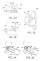
- FIGS. 3A-3B depict exemplary movable couplings for a display boom of a head-mounted display, in accordance with embodiments of the present technology
- FIG. 3C depicts a partial, cross-section view of a releasable coupling for a display boom of a head-mounted display, in accordance with an embodiment of the present technology
- FIG. 3D depicts the releasable coupling of FIG. 3C engaged for releasing the display boom, in accordance with an embodiment of the present technology
- FIG. 4A is an angled, perspective, cross-section view of a strap of an attachment mechanism of a head-mounted display, in accordance with an embodiment of the present technology
- FIG. 4B is a partial, cross-section view of a component of a head-mounted display configured for securement to the strap depicted in FIG. 4A , in accordance with an embodiment of the present technology;
- FIG. 5A depicts an exemplary spring-based tensioning mechanism, in accordance with an embodiment of the present technology
- FIG. 5B depicts an exemplary screw-based tensioning mechanism, in accordance with an embodiment of the present technology
- FIG. 5C depicts an elastically-deformable tensioning mechanism, in accordance with an embodiment of the present technology
- FIG. 6A depicts a partial, cross-section view of a releasable coupling for a display boom, in accordance with an embodiment of the present technology
- FIG. 6B depicts the releasable coupling of FIG. 6A engaged to release a portion of the display boom, in accordance with an embodiment of the present technology
- FIGS. 7A-7B depict an exemplary strap-based tensioning mechanism for a head-mounted display, in accordance with an embodiment of the present technology
- FIGS. 8A-8B depict an exemplary head-mounted display mounted on an item of headwear, in accordance with an embodiment of the present technology
- FIGS. 9A-9B depict exemplary display modules, in accordance with embodiments of the present technology.
- FIG. 10 depicts an exemplary head-mounted display mounted on an item of headwear, in accordance with an embodiment of the present technology
- FIG. 11 depicts a harness-coupling component attached to an item of headwear, in accordance with an embodiment of the present technology
- FIGS. 12A-12B depict an exemplary sound-dampening ear-cover assembly without a display boom, in accordance with an embodiment of the present technology
- FIGS. 13A-13B depict a partial, cross-section view of the sound-dampening ear-cover assembly shown in FIGS. 12A-12B , in accordance with an embodiment of the present technology
- FIGS. 14A-14B depict the sound-dampening ear-cover assembly of FIGS. 12A-12B with a display boom mounted at different locations, in accordance with an embodiment of the present technology
- FIGS. 15A-15B depict exemplary releasable couplings for a display module, in accordance with embodiments of the present technology
- FIGS. 16A-16C depict a variety of display modules each having a different display characteristic, in accordance with embodiments of the present technology
- FIGS. 17A-17B depict a display module having multiple display portions, in accordance with an embodiment of the present technology
- FIGS. 18A-18B depict a display module with interchangeable display portions, in accordance with an embodiment of the present technology
- FIG. 19 depicts a display module having first and second display portions that provide different viewing states, in accordance with an embodiment of the present technology
- FIGS. 20A-20B depict a display module with a common display portion providing different viewing states, in accordance with an embodiment of the present technology.
- FIG. 21 is a block diagram of an exemplary method of adjusting a head-mounted display, in accordance with an embodiment of the present technology.
- an exemplary head-mounted display may include a selection of components in a modular configuration, and also, may include an attachment mechanism for securing the selection of components to an item of headwear (e.g., a helmet), allowing the head-mounted display to be used in a variety of different applications.
- a display module for the head-mounted display may be interchangeable and selected based on a desired corresponding display characteristic.
- FIG. 1 a block diagram of an exemplary computing device 2 suitable for use with embodiments of the present technology is provided.
- Computing device 2 includes a bus 18 that may directly or indirectly couple various components together, including memory 4 , processor(s) 6 , presentation component(s) 8 , radio(s) 10 , input/output (I/O) port(s) 12 , input/output (I/O) component(s) 14 , and power supply 16 .
- I/O input/output
- FIG. 1 may be plural.
- computing device 2 might include multiple processors and/or multiple radios.
- additional or alternative components may be provided with computing device 2 , and the configuration shown in FIG. 1 is merely exemplary.
- Memory 4 may take the form of the memory components described herein. Thus, further elaboration will not be provided, but it should be noted that memory 4 may include any type of tangible medium that is capable of storing information, such as a database. A database may include any collection of records, data, and/or other information. In one embodiment, memory 4 may include a set of embodied computer-executable instructions that, when executed, facilitate various functions or steps disclosed herein. These embodied instructions will be referred to as “instructions” or an “application” for short.
- Presentation component 8 may include a display, a speaker, and/or other components that can present information through visual, auditory, and/or other tactile cues (e.g., a display, a screen, a lamp, a light-emitting diode (LED), a graphical user interface (GUI), or even a lighted keyboard).
- visual, auditory, and/or other tactile cues e.g., a display, a screen, a lamp, a light-emitting diode (LED), a graphical user interface (GUI), or even a lighted keyboard.
- Radio 10 may facilitate communication with a network, and may additionally or alternatively facilitate other types of wireless communications, such as Wi-Fi, WiMAX, LTE, Bluetooth, and/or other VoIP communications.
- the radio 10 may be configured to support multiple technologies, and/or multiple radios may be configured and utilized to support multiple technologies.
- I/O ports 12 may take a variety of forms. Exemplary I/O ports may include a USB jack, a stereo jack, an infrared port, a firewire port, and/or other proprietary communications ports. Input/output (I/O) components 14 may comprise one or more keyboards, microphones, speakers, touchscreens, and/or any other item usable to directly or indirectly input/output data to or from the computing device 2 .
- Power supply 16 may include batteries, fuel cells, and/or any other component that may act as a power source to supply power to computing device 2 or to other components, including through one or more electrical connections or couplings. Power supply 16 may be configured to selectively supply power to different components independently and/or concurrently.
- the head-mounted display 20 includes a display module 24 , a display boom 26 , a base 28 coupled to the display boom 26 , a power source 30 , a communication component 40 , and an electronics module 32 mounted on an item of headwear 22 .
- the headwear 22 is a helmet, although the head-mounted display 20 may be configured for securement to other types of headwear as well.
- the head-mounted display 20 further includes a camera 38 attached to the electronics module 32 .
- the electronics module 32 provides a consolidation of one or more components of the head-mounted display 20 (e.g., computer processor(s), memory, position-tracking component(s), communication component(s), etc.). However, it should be noted that the components associated with the electronics module 32 may also be distributed at other locations about the head-mounted display 20 and communicatively connected to each other as necessary, rather than consolidated as shown in FIGS. 2A-2B .
- the display boom 26 includes a first end 44 coupled to the display module 24 and a second end 46 coupled to the base 28 .
- the display module 24 includes at least one display portion 42 and provides a corresponding display characteristic.
- the display portion 42 may include a waveguide optic that is at least partially transparent for providing an augmented reality display on which text, images, and/or other objects may be shown interactively with a real-time viewed-environment.
- the display module 24 and the display boom 26 are secured to each other with a releasable coupling 48 (non-limiting examples of which are depicted in FIGS. 15A-15B ).
- the releasable coupling 48 includes a first mateable coupling 50 attached to the first end 44 of the display boom 26 and a second mateable coupling 52 attached to the display module 24 .
- the display module 24 may be interchangeable with other display modules each having a separate mateable coupling that is also releasably securable to the first mateable coupling 50 (e.g., by having a similar configuration as the second mateable coupling 52 ).
- the other display modules may also provide different corresponding display characteristics than the display module 24 .
- the second end 46 of the display boom 26 is movably coupled to the base 28 with a movable coupling 56 .
- the display boom 26 also includes first and second movable joints 58 , 60 which, in combination, provide articulation of the display module 24 relative to the base 28 .
- the display boom 26 further includes first and second releasable couplings 62 , 64 that allow portions of the display boom 26 to be detached, such as to allow modular configuration. It should be noted that the first and second movable joints 58 , 60 and the first and second releasable couplings 62 , 64 depicted in FIGS. 2A-2B may or may not be used, depending on the desired functionality and configuration of the head-mounted display 20 .
- the head-mounted display 20 further includes an attachment mechanism 66 configured to attach the components of the head-mounted display 20 (e.g., the electronics module 32 , the display boom 26 , the power source 30 , etc.) to the headwear 22 .
- the attachment mechanism 66 includes rigid coupling elements 68 and a strap 70 which may be used together to secure the various components of the head-mounted display 20 to the headwear 22 . As shown in FIG.
- each of the rigid coupling elements 68 may include a concave (i.e., recessed) channel 72 for engaging an edge of the headwear 22 , and additionally, a tensioning mechanism 74 may be used with one or more of the rigid coupling elements 68 for securing a corresponding rigid coupling element 68 against the headwear 22 .
- the head-mounted display 20 shown in FIGS. 2A-2B also includes a microphone 78 attached to the display module 24 .
- the microphone 78 may alternatively be positioned on the display boom 26 , and may be configured to receive audio input from a user and communicate with one or more computer processors and/or communication components of the head-mounted display 20 .
- any of the components of the head-mounted display 20 may be communicatively interconnected with each other.
- communication between components may be provided using a wireless connection (e.g., Bluetooth) and/or a wired-connection, such as the wired connection 80 shown in FIGS. 2A-2B , which may extend through any part of the head-mounted display 20 as needed to reach different components.
- the head-mounted display 20 may also be configured for wireless communication over a network, such as a cellular, Wi-Fi, Bluetooth, and/or satellite network, as well as any other wireless communication modality, using a communication component that is communicatively connected to computer processors associated with the head-mounted display 20 .
- the communication component (e.g., which may include a radio and antenna) may also be configured to provide, in conjunction with a position-tracking component, location-tracking ability for the head-mounted display 20 through signal triangulation, a global positioning system (GPS) signal, or another tracking method. Additionally, each of the components of the head-mounted display 20 requiring power may be connected to the power source 30 through one or more power cables extending through the various parts of the head-mounted display 20 .
- GPS global positioning system
- the display boom 26 of the head-mounted display 20 shown in FIGS. 2A-2B is provided in multiple positions, in accordance with an embodiment of the present technology.
- the display boom 26 is moved from a first position 82 to a second position 84 .
- the first position 82 may be considered a viewing position, at which the display module 24 is at least partially in front of a user's face
- the second position 84 may be considered a retracted position, at which the display module 24 is away from the user's face.
- At least one of the first and second positions 82 , 84 may be user-configurable, and may result in activation, deactivation, and/or changed operation of one or more components of the head-mounted display 20 .
- the head-mounted display 20 may be configured such that components and functions thereof can change depending on whether the display boom 26 is in the first position 82 or the second position 84 .
- the display module 24 including any components thereof (e.g., microphone, eye-tracking camera, display, etc.), may have full operation, and when the display boom 26 is in the second position 84 , the display module 24 and any components thereof may be at least partially adjusted in operation (e.g., put into sleep mode to save power).
- Certain components, such as a position-tracking component may remain in operation regardless of the adjustments to the display boom 26 , depending on the configuration.
- first and second movable couplings 86 , 88 usable to attach a display boom, such as the display boom 26 shown in FIGS. 2A-2B , to a base of a head-mounted display, such as the base 28 of the head-mounted display 20 shown in FIGS. 2A-2B , are provided, in accordance with an embodiment of the present technology.
- the first movable coupling 86 shown in FIG. 3A is a rotatable coupling for providing rotational movement of a corresponding display boom
- the second movable coupling 88 shown in FIG. 3B is a ball-joint-type coupling for providing multi-axis movement of a corresponding display boom relative to a base.
- FIGS. 3C-3D a partial, cross-section view of an exemplary releasable coupling 90 for a display boom of a head-mounted display, such as the display boom 26 of the head-mounted display 20 shown in FIGS. 2A-2B , is provided, in accordance with an embodiment of the present technology.
- the releasable coupling 90 is a mechanical coupling having first and second releasing mechanisms 92 , 94 that can be engaged (i.e., depressed) to decouple an engaging mount 96 from a base mount 95 to allow a display boom to be released from a head-mounted display.
- the releasable coupling 90 is configured to move between a first securing position, as shown in FIG. 3C , and a second releasing position, as shown in FIG. 3D .
- FIG. 4A a cross-section view of a strap 98 for a head-mounted display, such as the head-mounted display 20 shown in FIGS. 2A-2B , is provided, in accordance with an embodiment of the present technology.
- the strap 98 may be rigid, semi-rigid, non-rigid, and/or may include an elastic resilience.
- the strap 98 may be permanently fixed to headwear, such as a helmet or hat. To this end, the strap 98 may function as more of a track for providing contacts for communication between various components, as will be described.
- the strap 98 can include a cable 102 , which may be a power and/or communications cable, extending through a channel 104 within the strap 98 .
- the strap 98 can also include a plurality of communication cables 106 exposed on an outer surface of the strap 98 .
- the communication cables 106 may be configured to mateably attach to a corresponding plurality of communication contacts 108 , as shown in FIG. 4B .
- the strap 98 itself may include integrated conductive lines having at least partially exposed, conductive surfaces that can provide similar communicative transmission to a cable.
- FIG. 4B a partial, cross-section view of a component 100 of a head-mounted display, such as the head-mounted display 20 shown in FIGS. 2A-2B , is provided, in accordance with an embodiment of the present technology.
- the component 100 includes the corresponding plurality of communication contacts 108 configured to be mateably connected to the plurality of communication cables 106 located on the outer surface of the strap 98 . Due to the extending and circumscribing nature of the plurality of communication cables 106 on the outer surface of the strap 98 , the component 100 , which may be, for example, the electronics module 32 depicted in FIGS. 2A-2B , may be secured to the strap 98 at a number of different locations while still maintaining a communicative connection. This flexibility in positioning the component 100 may more easily allow weight distribution of an associated head-mounted display to be accomplished.
- FIGS. 5A-5C a variety of exemplary tensioning mechanisms 110 , 112 , 114 that may be used to attach components of a head-mounted display to an item of headwear are provided, in accordance with an embodiment of the present technology.
- FIG. 5A depicts an exemplary spring-based tensioning mechanism 110 , which includes a movable element 116 , a fixed element 118 , a plunger 122 , and a spring 120 that biases the movable element 116 and the fixed element 118 away from each other, controlling a size of a channel 124 formed in the spring-based tensioning mechanism 110 , allowing for engagement with an item of headwear.
- FIG. 5B depicts a screw-based tensioning mechanism 112 that includes a movable element 126 , a fixed element 128 , and a screw 130 .
- a channel 132 is formed between the movable element 126 and the fixed element 128 , and the screw 130 may be used to bias the movable element 126 towards the fixed element 128 to change the size of the channel 132 to provide a force against an edge of an item of headwear positioned in the channel 132 , allowing the tensioning mechanism to be secured to the item of headwear.
- FIG. 5C depicts an elastically deformable tensioning mechanism 114 that includes an elastically deformable element 115 , which may be formed from any material that provides an elastic resistance when biased (e.g., flexible plastic, rubber, etc.).
- the elastically deformable tensioning mechanism 114 may be pulled open to engage an edge of an item of headwear, and then released to provide a force against the edge of the item of headwear to attach the elastically deformable tensioning mechanism 114 to the same. It should be noted that the tensioning mechanisms 110 , 112 , 114 shown in FIGS.
- tensioning mechanisms including those with different attachment configurations (e.g., magnetic, adhesive, buttons, hook-and-loop fasteners, harnesses, etc.) are possible and contemplated in addition to the examples provided herein.
- FIGS. 6A-6B a partial, cross-section view of a releasable coupling 134 for a display boom of a head-mounted display, such as the display boom 26 of the head-mounted display 20 shown in FIGS. 2A-2B , is provided, in accordance with an embodiment of the present technology.
- the releasable coupling 134 shown in FIGS. 6A-6B is a mechanical coupling, the components of which are movable between a first securing position 136 , as shown in FIG. 6A , and a second releasing position 138 , as shown in FIG. 6B .
- Movement between the first and second positions 136 , 138 occurs through engagement of first and second releasing mechanisms 140 , 142 , which, when engaged as shown in FIG. 6B , decouple an engaging mount 144 of the releasable coupling 134 from a base mount 146 .
- first and second releasing mechanisms 140 , 142 which, when engaged as shown in FIG. 6B , decouple an engaging mount 144 of the releasable coupling 134 from a base mount 146 .
- the releasing mechanism 134 depicted in FIGS. 6A-6B is exemplary, and other configurations (e.g., having mechanical couplings, magnetic couplings, male-female couplings, etc.) are possible and contemplated herein.
- an exemplary strap-based tensioning mechanism 148 for a head-mounted display such as the head-mounted display 20 shown in FIGS. 2A-2B , is provided, in accordance with an embodiment of the present technology.
- the strap-based tensioning mechanism 148 may be used to tighten or secure a strap, such as the strap 70 shown in FIGS. 2A-2B , against an item of headwear, such as a helmet.
- the strap-based tensioning mechanism 148 may be configured to move between a first configuration 150 providing a first strap circumference, as shown in FIG. 7A , and a second configuration 152 providing a second strap circumference, as shown in FIG. 7B , the second circumference being smaller than the first circumference for tightening against the associated item of headwear.
- FIGS. 8A-8B another exemplary head-mounted display 154 is provided, in accordance with an embodiment of the present technology.
- the head-mounted display 154 shown in FIGS. 8A-8B is mounted on the item of headwear 22 that is also depicted in FIGS. 2A-2B , and includes a display module 156 , a display boom 158 , a power source 162 , a camera 164 , and an electronics module 166 .
- the electronics module 166 may include a computer processor, a communication component, a position-tracking component, and/or other integrated system components in a consolidated configuration. It should also be noted that, in different configurations, the components associated with the electronics module 166 may be distributed about the head mounted display 154 , rather than consolidated, as shown in FIGS. 8A-8B .
- a communication cable 174 is provided that extends from the electronics module 166 , through the display boom 158 , and to the display module 156 , to provide communication between the display module 156 and the one or more computer processors located within the electronics module 166 .
- the head-mounted display 154 also includes an attachment mechanism 176 for securing the display boom 158 to the item of headwear 22 .
- the attachment mechanism 176 includes rigid coupling elements 178 that attach to edges of the item of headwear 22 , and a strap 180 which, in conjunction with the rigid coupling elements 178 , may be used to secure the display boom 158 , the electronics module 166 , and the power source 162 to the headwear 22 .
- the display boom 158 includes a first end 182 attached to a first rotatable coupling 184 and a second end 190 attached to a second rotatable coupling 192 .
- the first rotatable coupling 184 is mounted on a first rigid coupling element 186 of the attachment mechanism 176 that is secured to a first side 188 of the headwear 22
- the second rotatable coupling 192 is attached to a second rigid coupling element 194 that is secured to a second side 196 of the headwear 22 .
- the display module 156 shown in FIGS. 8A-8B is coupled to the display boom 158 between the first end 182 and the second end 190 of the display boom 158 . Additionally, the display boom 158 is movable (i.e., rotatable) about the first and second rotatable couplings 184 , 192 . This movement allows a user to move the display boom 158 between a first position (shown in FIGS. 8A and 8B ) where the display module 156 is positioned in front of a user's face, and a second position, where the display boom 158 and display module 156 are at least partially away from the user's face (e.g., folded up over a brim 198 of the headwear 22 ).
- the display boom 158 of the head-mounted display 154 shown in FIGS. 8A-8B further includes a component module 200 attached adjacent to the display module 156 .
- the component module 200 may provide additional components and functionality, such as a forward-facing camera 202 (e.g., standard, infrared, and/or night vision) for capturing images and/or video, a rearward-facing camera for tracking eye movement of a user (see FIG. 16C for an example), different sensors and detectors (e.g., a temperature sensor, air-quality sensor, radiation sensor, etc.) for detecting environmental conditions, and/or any other components for a particular application.
- a forward-facing camera 202 e.g., standard, infrared, and/or night vision
- a rearward-facing camera for tracking eye movement of a user
- different sensors and detectors e.g., a temperature sensor, air-quality sensor, radiation sensor, etc.
- exemplary first and second display modules 204 , 206 alternatively coupled to a display boom 212 are provided, in accordance with embodiments of the present technology.
- the first exemplary display module 204 is coupled to the display boom 212 with a first movable attachment 208 .
- the first display module 204 depicted in FIG. 9A includes a non-transparent display (e.g., a micro display, which may comprise at least one of a LCD, LED display, OLED display, DLP display, etc.) that is adjustable relative to the display boom 212 , which may be similar to the display boom 158 shown in FIGS. 8A-8B .
- a non-transparent display e.g., a micro display, which may comprise at least one of a LCD, LED display, OLED display, DLP display, etc.
- the first display module 204 further includes a locking mechanism 214 , which may be engaged to allow the first display module 204 to rotate relative to the display boom 212 (e.g., by pressing the button 215 ), and then disengaged to allow the first display module 204 to remain in a fixed position relative to the display boom 212 (e.g., by releasing the button 215 ).
- the second exemplary display module 206 is coupled to the display boom 212 with a second movable attachment 210 .
- the second display module 206 includes an optic that is transparent, partially transparent, and/or selectively transparent, and may be configured to provide an augmented reality display in which text, images, and/or other objects are shown in conjunction with a real-time environment viewed by a user through the optic (e.g., the optic may be a waveguide optic).
- the second movable attachment 210 allows the second display module 206 to move relative to the display boom 212 in a number of different directions.
- the second display module 206 may be fixed relative to the display boom 212 using the locking mechanism 214 and button 215 , as discussed with respect to FIG. 9A .
- the locking mechanism 214 may or may not be used, and retaining the position of the first and second display modules 204 , 206 relative to the display boom 212 may be provided through frictional resistance from the first and second movable attachments 208 , 210 .
- the head-mounted display 216 includes a display module 220 , a display boom 222 , a power source 224 , and an electronics module 226 , which may include one or more computer processors, position-tracking components, communication components, etc., in addition to other possible or alternative components. Components of the electronics module 226 may also be distributed about the head-mounted display 216 , rather than consolidated in the electronics module 226 as in FIG. 10 .
- the head-mounted display 216 also includes an attachment mechanism 228 having rigid coupling elements 230 and a strap 234 , the rigid coupling elements 230 configured to engage edges 232 of the headwear 218 , and the strap 234 configured to secure the rigid coupling elements 230 and the components of the head-mounted display 216 circumferentially about the headwear 218 .
- FIG. 10 depicts a configuration having the display module 220 and the display boom 222 mounted on a front portion of the headwear 218 , which in FIG. 10 is a full-brim-type helmet.
- the display boom 222 is also coupled to the electronics module 226 with a rotatable coupling 227 , which allows the display module 220 to be rotated up and down between a first position in front of a user's face (shown in FIG. 10 ) and a second position that is at least partially away from a user's face.
- the display module 220 is also positioned at an end of the display boom 222 off to a first side 229 , and an additional component module 231 (e.g., which may include forward and/or rearward-facing cameras, sensors, microphones, etc.) is coupled to the display boom 222 and positioned off to a second side 233 .
- an additional component module 231 e.g., which may include forward and/or rearward-facing cameras, sensors, microphones, etc.
- an exemplary harness-coupling component 236 for attaching a head-mounted display to an item of headwear 242 is provided, in accordance with an embodiment of the present technology.
- the harness-coupling component 236 includes a plurality of receiving-channels 238 which are attachable to a harness-structure 240 of the item of headwear 242 .
- the harness-coupling component 236 is further coupled to a base 244 , which may be movably coupled to a display boom 246 (only partially shown), which may be similar to the display boom 26 shown in FIGS. 2A-2B .
- the harness-coupling component 236 may be used in conjunction with other components of an attachment mechanism, such as those of the attachment mechanism 66 shown in FIGS. 2A-2B .
- FIGS. 12A-12B a partial depiction of an exemplary head-mounted display 248 that includes a sound-dampening ear-cover assembly 250 is provided, in accordance with an embodiment of the present technology.
- head-mounted displays and attachment mechanisms for headwear such as helmets
- embodiments herein may be configured for use with other protective and/or utility-based equipment, such as eye, ear, face, and/or head protection.
- the head-mounted displays discussed herein may be configured to satisfy various safety standards, such as those outlined in Section 5(a)(1) of the Occupation Safety and Health Act (“OSHA”), as well as 29 C.F.R. 1910.95 for hearing protection, 29 C.F.R. 1910.135 for head protection, and 29 C.F.R. 1910.33 for eye and face protection, in addition to other standards.
- OSHA Occupation Safety and Health Act
- the sound-dampening ear-cover assembly 250 includes a first portion 256 and a second portion 258 that are movably coupled to each other with a rotatable coupling 254 .
- the sound-dampening ear-cover assembly 250 further includes a lever 260 that can be used to move the sound-dampening ear-cover assembly 250 between a first configuration 262 , shown in FIG. 12A , where the first and second portions 256 , 258 are in a first position 251 relative to each other, and a second configuration 264 , as shown in FIG.
- first and second portions 256 , 258 are in a second position 253 relative to each other (the positions 251 , 253 depicted in FIGS. 12A and 12B are merely exemplary).
- the lever 260 may be attached to the first portion 256 , the second portion 258 (as shown in FIGS. 12A-12B ), and/or the rotatable coupling 254 , in exemplary embodiments.
- the second portion 258 is in a relatively lowered position, where it may abut and/or be compressed against a side of a wearer's head, such that it substantially encloses a wearer's ear within the sound-dampening ear-cover assembly 250 .
- the second portion 258 is in a relatively raised position, such that it may be moved away from the wearer's head (relative to the first configuration 262 ), to more fully expose a wearer's ear from within the sound-dampening ear-cover assembly 250 .
- the head-mounted display 248 depicted in FIGS. 12A-12B provides the option of securing the second portion 258 against or towards a wearer's head to provide greater sound protection by more fully enclosing the wearer's ear, and also, moving the second portion 258 away from the wearer's head with the lever 260 to provide less sound protection by less fully enclosing the wearer's ear, relatively speaking.
- latches, clips, straps, and/or other securement components may be used for securing the first and second portions 256 , 258 in the first position 251 and/or the second position 253 , or in other positions.
- the 12A-12B also includes a mounting portion 272 that extends through the sound-dampening ear-cover assembly 250 .
- the mounting portion 272 may integrally include one or more components of the head-mounted display 248 (e.g., one or more computer processors and/or communication components) and may provide an attachment point for mounting a display boom, as discussed further with respect to FIGS. 14A-14B .
- FIGS. 13A-13B a cross-section of the sound-dampening ear-cover assembly 250 depicted in FIGS. 12A-12B is provided, in accordance with an embodiment of the present technology.
- FIG. 13A when the sound-dampening ear-cover assembly 250 is in the first configuration 262 , the first and second portions 256 , 258 are in the first position 251 , with the second portion 258 in a relatively lowered position, allowing it to at least partially surround and/or enclose a wearer's ear 265 .
- FIG. 13A when the sound-dampening ear-cover assembly 250 is in the first configuration 262 , the first and second portions 256 , 258 are in the first position 251 , with the second portion 258 in a relatively lowered position, allowing it to at least partially surround and/or enclose a wearer's ear 265 .
- FIGS. 14A-14B the head-mounted display 248 depicted in FIGS. 12A-12B is again provided with exemplary display boom attachments, in accordance with embodiments of the present technology.
- a first display boom 268 is provided, which is secured to the mounting portion 272 of the head-mounted display 248 with a rotatable coupling 270 .
- the first display boom 268 further includes a releasable coupling 274 that allows the first display boom 268 to be secured/released from the rotatable coupling 270 (e.g., for replacement with another type of display boom).
- the releasable coupling 274 may be similar to the releasable coupling 134 shown in FIGS. 6A-6B .
- a second display boom 276 is provided, which is secured to the sound-dampening ear-cover assembly 250 .
- the second display boom 276 is movably coupled to the second portion 258 of the sound-dampening ear-cover assembly 250 with a rotatable coupling 275 .
- the second display boom 276 also includes a releasable coupling 278 , which may be similar to the releasable coupling 134 shown in FIGS. 6A-6B , that allows the second display boom 276 to be secured/released from the sound-dampening ear-cover assembly 250 .
- the display booms 268 , 276 and mounting configurations thereof shown in FIGS. 14A-14B are merely exemplary, and other configurations and locations are possible and contemplated.
- a first releasable coupling 280 for attaching a display module 284 to a display boom 286 of a head-mounted display, such as the head-mounted display 20 show in FIGS. 2A-2B is provided, in accordance with an embodiment of the present technology.
- the first releasable coupling 280 is a mechanical coupling having a male-female connector 292 and a releasing mechanism 294 .
- the releasable coupling 280 includes a first mateable coupling 288 located at an end of the display boom 286 , and a second mateable coupling 290 located on the display module 284 .
- the first and second mateable couplings 288 , 290 can be releasably secured to each other to attach the display module 284 to the display boom 286 .
- the first releasable coupling 280 may be configured such that a different display module having a separate mateable coupling, which is configured like the second mateable coupling 290 shown in FIG. 15A , may be joined to the first mateable coupling 288 in order to utilize a display module with a different corresponding display characteristic than the display module 284 .
- a second releasable coupling 282 for attaching a display module 285 to a display boom 287 of a head-mounted display, such as the head-mounted display 20 show in FIGS. 2A-2B is provided, in accordance with an embodiment of the present technology.
- the second releasable coupling 282 is magnetic-based and includes a first mateable coupling 296 with a first magnetic polarity and a second mateable coupling 298 with a second magnetic polarity that is opposite to the first magnetic polarity, such that, as a result, the first and second mateable couplings 296 , 298 are magnetically attracted to each other.
- the second releasable coupling 282 may be configured such that a different display module having a separate mateable coupling, which is configured like the second mateable coupling 298 shown in FIG. 15B , may be joined to the first mateable coupling 296 in order to utilize a display module with a different corresponding display characteristic than the display module 285 .
- exchanging one display module for another display module having a different corresponding display characteristic may result in the computer processor(s) of an associated head-mounted display adapting to the new display characteristic.
- different display modules having different corresponding display characteristics may each have hardware identifiers and/or embedded metadata that, when detected by a processor of a head-mounted display, such as upon attachment of a display module with a releasable coupling, may cause the processor to load appropriate drivers to reconfigure the visual output to appropriately function with the new display module.
- a user might manually load appropriate drivers and/or display configurations for one or more display modules that may be connected to a head-mounted display, or for a currently connected/used display module.
- a processor of a head-mounted display may store, such as in memory, a number of different drivers and/or applications configured to adapt the various functions of the head-mounted display to a display characteristic of an attached display module.
- FIG. 16A depicts a first display module 300 that includes a first display portion 306 coupled to a base 308 .
- the first display portion 306 comprises a first waveguide optic 305 that may be transparent, partially transparent, and/or selectively transparent (e.g., for providing images, text, and/or other visual elements thereon in an augmented reality display).
- the base 308 may include a mateable coupling, such as the second mateable coupling 298 shown in FIG.
- FIG. 16B depicts a second display module 302 that comprises a second waveguide optic 307 with a circular shape to provide a different field of view than the first waveguide optic 305 shown in FIG. 16A .
- the second waveguide optic 307 is once again secured to the base 308 , which is attached to the display boom 310 .
- FIG. 16C depicts a third display module 304 that includes a display portion 312 that is non-transparent (e.g., a micro display, which may comprise at least one of a LCD, LED display, OLED display, DLP display, etc.) for displaying text, images, and/or other objects (e.g., a PDF with black text on white background).
- the third display module 304 is attached to the display boom 310 and further includes a user-facing camera 314 , which may be used to track eye movement of a user wearing the third display module 304 (e.g., for document navigation), and a microphone 316 , which may be used for receiving audio input from a user (e.g., voice commands, communications over a wireless network connection, etc.).
- a user-facing camera for tracking eye movement and/or a microphone for receiving audio input, in addition to other components and features.
- an exemplary display module 318 having first and second display portions 320 , 322 is provided, in accordance with an embodiment of the present technology.
- the first and second display portions 320 , 322 are secured to each other, and also, rotatably coupled to a base 324 with a rotatable coupling 326 .
- the base 324 is releasably attached to an end of a display boom 328 .
- the first and second display portions 320 , 322 are coupled to each other at an angle, such that the first and second display portions 320 , 322 are non-coplanar relative to each other.
- the first and second display portions 320 , 322 may each remain more angled towards a user's eye than if the first and second display portions 320 , 322 were coplanar.
- the angle of the first and second display portions 320 , 322 may be configured based on a user's needs or preference.
- the first display portion 320 may comprise a micro display and the second display portion 322 may comprise a waveguide optic, allowing multiple visual displays to be provided on the display module 318 .
- the display module 318 may be activated, deactivated, and/or otherwise have its function modified by rotating the first and second display portions 320 , 322 in unison about a common axis 330 , as shown in FIG. 17B .
- a display module 332 having first and second display portions 334 , 336 is provided, in accordance with an embodiment of the present technology.
- the first display portion 334 is non-transparent (e.g., a micro display, which may comprise at least one of a LCD, LED display, OLED display, DLP display, etc.) and the second display portion 336 is transparent, partially transparent, and/or selectively transparent (e.g., a waveguide optic for providing an augmented reality display).
- the first and second display portions 334 , 336 are coupled such that they are coplanar to each other (they may also be at an angle as shown in FIGS.
- the releasable mount 338 allows one or both of the first and second display portions 334 , 336 to be independently interchangeable, allowing customization of a display characteristic of the display module 332 .
- a display module 342 having first and second display portions 344 , 346 (i.e., a dual-display) is provided, in accordance with an embodiment of the present technology.
- the first display portion 344 is non-transparent (e.g., a micro display, which may comprise at least one of a LCD, LED display, OLED display, DLP display, etc.) and is shown displaying text for a user to view at one viewing angle
- the second display portion 346 is coupled to the first display portion 344 and is at least partially transparent (e.g., a waveguide optic) and is showing a combination of a user-viewed environment and displayed text/objects 348 at a second viewing angle (i.e., an augmented reality display).
- the augmented reality display provides an interactive display of information, and may be used in conjunction with audible instructions provided concurrently from one or more computer processors of an associated head-mounted display.
- the second display portion 346 is above the first display portion 344 relative to a user's field of view.
- a display module 350 configured to provide multiple viewing states on a common display portion 352 is provided, in accordance with an embodiment of the present technology.
- the display module 350 shown in FIGS. 20A-20B is configured to go from a first state 354 , as shown in FIG. 20A , that is non-transparent (e.g., providing black text on a white background) to a second state 356 , as shown in FIG. 20B , that is at least partially transparent (e.g., an augmented reality display).
- This configuration allows multiple viewing states (e.g., one for reviewing a document and one for seeing a real-time display of the instructions from the document in the context of the actual environment viewed by the user) to be viewed interchangeably during use of an associated head-mounted display.
- a block diagram of an exemplary method 2100 of adjusting a head-mounted display is provided, in accordance with an embodiment of the present technology.
- a head-mounted display such as the head-mounted display 20 shown in FIGS. 2A-2B .
- the head-mounted display may comprise a display boom, such as the display boom 26 shown in FIGS. 2A-2B , having a first end and a second end, such as the first end 44 and the second end 46 shown in FIGS. 2A-2B , the display boom movably coupled to a base, such as the base 28 shown in FIGS.
- the first display module located at the second end, one or more computer processors, a power source, a first display module, such as the display module 24 shown in FIGS. 2A-2B , configured to provide multiple viewing states, and a releasable coupling, such as the releasable coupling 48 shown in FIGS. 2A-2B , comprising a first mateable coupling, such as the first mateable coupling 50 shown in FIGS. 2A-2B , and a second mateable coupling, such as the second mateable coupling 52 shown in FIGS. 2A-2B .
- the first mateable coupling may be located at the first end of the display boom, and the second mateable coupling may be located on the first display module.
- the first display module is releasably secured to the display boom by securing the first mateable coupling to the second mateable coupling.
Abstract
Description
Claims (20)
Priority Applications (6)
| Application Number | Priority Date | Filing Date | Title |
|---|---|---|---|
| US15/390,363 US10437070B2 (en) | 2016-12-23 | 2016-12-23 | Interchangeable optics for a head-mounted display |
| CN201780085636.2A CN110249254B (en) | 2016-12-23 | 2017-12-06 | Interchangeable optics for head-mounted displays |
| PCT/US2017/064898 WO2018118432A1 (en) | 2016-12-23 | 2017-12-06 | Interchangeable optics for a head-mounted display |
| EP17884064.1A EP3559729A4 (en) | 2016-12-23 | 2017-12-06 | Interchangeable optics for a head-mounted display |
| JP2019555414A JP7012744B2 (en) | 2016-12-23 | 2017-12-06 | Module component for head-mounted display |
| US16/584,285 US11340465B2 (en) | 2016-12-23 | 2019-09-26 | Head-mounted display with modular components |
Applications Claiming Priority (1)
| Application Number | Priority Date | Filing Date | Title |
|---|---|---|---|
| US15/390,363 US10437070B2 (en) | 2016-12-23 | 2016-12-23 | Interchangeable optics for a head-mounted display |
Related Child Applications (1)
| Application Number | Title | Priority Date | Filing Date |
|---|---|---|---|
| US16/584,285 Continuation US11340465B2 (en) | 2016-12-23 | 2019-09-26 | Head-mounted display with modular components |
Publications (2)
| Publication Number | Publication Date |
|---|---|
| US20180180894A1 US20180180894A1 (en) | 2018-06-28 |
| US10437070B2 true US10437070B2 (en) | 2019-10-08 |
Family
ID=62627127
Family Applications (2)
| Application Number | Title | Priority Date | Filing Date |
|---|---|---|---|
| US15/390,363 Active US10437070B2 (en) | 2016-12-23 | 2016-12-23 | Interchangeable optics for a head-mounted display |
| US16/584,285 Active US11340465B2 (en) | 2016-12-23 | 2019-09-26 | Head-mounted display with modular components |
Family Applications After (1)
| Application Number | Title | Priority Date | Filing Date |
|---|---|---|---|
| US16/584,285 Active US11340465B2 (en) | 2016-12-23 | 2019-09-26 | Head-mounted display with modular components |
Country Status (5)
| Country | Link |
|---|---|
| US (2) | US10437070B2 (en) |
| EP (1) | EP3559729A4 (en) |
| JP (1) | JP7012744B2 (en) |
| CN (1) | CN110249254B (en) |
| WO (1) | WO2018118432A1 (en) |
Cited By (1)
| Publication number | Priority date | Publication date | Assignee | Title |
|---|---|---|---|---|
| US11857378B1 (en) * | 2019-02-14 | 2024-01-02 | Onpoint Medical, Inc. | Systems for adjusting and tracking head mounted displays during surgery including with surgical helmets |
Families Citing this family (18)
| Publication number | Priority date | Publication date | Assignee | Title |
|---|---|---|---|---|
| US10437070B2 (en) * | 2016-12-23 | 2019-10-08 | Realwear, Inc. | Interchangeable optics for a head-mounted display |
| US20190008228A1 (en) * | 2016-12-30 | 2019-01-10 | David Francis Ramey | Integrated non-conflicting headgear platform system and method |
| DK3363312T3 (en) * | 2017-02-17 | 2021-02-01 | Savox Communications Oy Ab Ltd | Adaptable mounting system for mounting one or more auxiliary devices on a helmet |
| US10928163B2 (en) * | 2017-10-04 | 2021-02-23 | Trent Zimmer | Ballistic helmet |
| US20200137336A1 (en) * | 2018-10-30 | 2020-04-30 | Bae Systems Information And Electronic Systems Integration Inc. | Interlace image sensor for low-light-level imaging |
| CN109581665A (en) * | 2019-01-02 | 2019-04-05 | 京东方科技集团股份有限公司 | A kind of display device and its display methods, wear-type virtual display device |
| GB201903152D0 (en) * | 2019-03-08 | 2019-04-24 | Dimensional Imaging Ltd | Helmet |
| KR20210151913A (en) * | 2019-04-16 | 2021-12-14 | 드림크래프트 어트랙션스 엘티디. | A two-piece headset with audio for augmented reality (AR) or virtual reality (VR) or mixed reality (MR). |
| US20210000650A1 (en) * | 2019-07-01 | 2021-01-07 | Focus Labs, LLC | Event-triggered eye occlusion |
| US11733529B1 (en) * | 2020-04-21 | 2023-08-22 | Apple Inc. | Load-distributing headband for head-mounted device |
| WO2021234832A1 (en) * | 2020-05-20 | 2021-11-25 | ヤマハ発動機株式会社 | Eye tracking device |
| US20230194881A1 (en) * | 2020-05-29 | 2023-06-22 | Vrmedia S.R.L. | System for augmented reality |
| USD968401S1 (en) | 2020-06-17 | 2022-11-01 | Focus Labs, LLC | Device for event-triggered eye occlusion |
| US11906748B1 (en) * | 2020-09-01 | 2024-02-20 | Apple Inc. | Support for head-mountable device |
| CA3210574A1 (en) * | 2021-03-12 | 2022-09-15 | Nicole Z. SUMMERSETT | Safety headwear systems and accessories |
| CA3218660A1 (en) * | 2021-05-13 | 2022-11-17 | Polaris Industries Inc. | Systems and methods for smart helmet |
| CN113805659A (en) * | 2021-09-17 | 2021-12-17 | 瑞欧威尔(上海)智能科技有限公司 | Head-mounted display device with live broadcast function |
| CN114236853B (en) * | 2022-01-26 | 2024-01-05 | 中煤科工开采研究院有限公司 | Split type mining AR glasses fixing device and using method thereof |
Citations (160)
| Publication number | Priority date | Publication date | Assignee | Title |
|---|---|---|---|---|
| US4944361A (en) | 1987-09-02 | 1990-07-31 | Ab Kompositprodukter S.K.-F.M. | Acoustic ear muff |
| US5046192A (en) | 1989-09-26 | 1991-09-10 | Ryder International Corporation | Headset sun visor |
| US5185807A (en) | 1991-05-08 | 1993-02-09 | David Clark Company Incorporated | Headset with multi-position stirrup assemblies |
| US5767820A (en) | 1995-05-09 | 1998-06-16 | Virtual Research Systems | Head-mounted visual display apparatus |
| US5796374A (en) * | 1996-03-08 | 1998-08-18 | Virtual Vision, Inc. | Support for a head mounted display system |
| US5806079A (en) | 1993-11-19 | 1998-09-08 | Smartpatents, Inc. | System, method, and computer program product for using intelligent notes to organize, link, and manipulate disparate data objects |
| US5815126A (en) | 1993-10-22 | 1998-09-29 | Kopin Corporation | Monocular portable communication and display system |
| US5850211A (en) | 1996-06-26 | 1998-12-15 | Sun Microsystems, Inc. | Eyetrack-driven scrolling |
| US5882137A (en) | 1996-06-25 | 1999-03-16 | Lemforder Metallwaren Ag | Process for preparing a low-friction ball joint, as well as low-friction ball joint |
| US5977935A (en) | 1993-08-12 | 1999-11-02 | Seiko Epson Corporation | Head-mounted image display device and data processing apparatus including the same |
| US6061064A (en) | 1993-08-31 | 2000-05-09 | Sun Microsystems, Inc. | System and method for providing and using a computer user interface with a view space having discrete portions |
| US6198462B1 (en) | 1994-10-14 | 2001-03-06 | Hughes Electronics Corporation | Virtual display screen system |
| US6222677B1 (en) * | 1999-04-12 | 2001-04-24 | International Business Machines Corporation | Compact optical system for use in virtual display applications |
| US6352228B1 (en) | 1998-08-29 | 2002-03-05 | FLM GmbH Foto-, Licht-und Messtechnisches Zubehör | Tripod head |
| US20020037770A1 (en) | 1998-08-10 | 2002-03-28 | Paul George V. | Real-time head tracking system for computer games and other applications |
| US20020044152A1 (en) | 2000-10-16 | 2002-04-18 | Abbott Kenneth H. | Dynamic integration of computer generated and real world images |
| US6434250B1 (en) | 1999-03-05 | 2002-08-13 | Parker I. Tsuhako | Stereo headset with angled speakers |
| US6456262B1 (en) | 2000-05-09 | 2002-09-24 | Intel Corporation | Microdisplay with eye gaze detection |
| US20020190947A1 (en) | 2000-04-05 | 2002-12-19 | Feinstein David Y. | View navigation and magnification of a hand-held device with a display |
| US20030020707A1 (en) | 2001-06-27 | 2003-01-30 | Kangas Kari J. | User interface |
| US6587700B1 (en) * | 1994-06-23 | 2003-07-01 | At&T Wireless Services, Inc. | Personal communicator with flip element display |
| US20030182713A1 (en) | 2002-03-04 | 2003-10-02 | Rolla Jose Maria | Fully collapsible headset |
| US6637883B1 (en) | 2003-01-23 | 2003-10-28 | Vishwas V. Tengshe | Gaze tracking system and method |
| US20040008158A1 (en) * | 2002-07-01 | 2004-01-15 | Axo Chi | Head-mounted display |
| US6708339B1 (en) | 2003-04-22 | 2004-03-23 | James Smith, Jr. | Sport helmet face guard |
| US6747611B1 (en) * | 2000-07-27 | 2004-06-08 | International Business Machines Corporation | Compact optical system and packaging for head mounted display |
| US20040218776A1 (en) | 2003-05-02 | 2004-11-04 | Rolla Jose Maria | Extensive mobility helmet headset and helmet which includes said headset |
| US6867752B1 (en) | 1998-08-31 | 2005-03-15 | Semiconductor Energy Laboratory Co., Ltd. | Portable information processing system |
| US20050083248A1 (en) * | 2000-12-22 | 2005-04-21 | Frank Biocca | Mobile face capture and image processing system and method |
| US20060044265A1 (en) | 2004-08-27 | 2006-03-02 | Samsung Electronics Co., Ltd. | HMD information apparatus and method of operation thereof |
| US20060048286A1 (en) * | 2003-01-27 | 2006-03-09 | Giuseppe Donato | Helmet for displaying environmental images in critical environments |
| US7103841B2 (en) | 2001-05-08 | 2006-09-05 | Nokia Corporation | Method and arrangement for providing an expanded desktop |
| US7113170B2 (en) | 2000-05-16 | 2006-09-26 | Swisscom Mobile Ag | Method and terminal for entering instructions |
| US7124425B1 (en) | 1999-03-08 | 2006-10-17 | Immersion Entertainment, L.L.C. | Audio/video system and method utilizing a head mounted apparatus with noise attenuation |
| US20070024507A1 (en) | 2003-06-02 | 2007-02-01 | Sanyo Electric Co., Ltd. | Antenna device |
| US20070052672A1 (en) | 2005-09-08 | 2007-03-08 | Swisscom Mobile Ag | Communication device, system and method |
| US20070130547A1 (en) | 2005-12-01 | 2007-06-07 | Navisense, Llc | Method and system for touchless user interface control |
| US7245737B2 (en) | 2003-11-13 | 2007-07-17 | Logitech Europe S.A. | Behind-the-head mounted personal audio set |
| US20070171193A1 (en) * | 2006-01-20 | 2007-07-26 | Denso Corporation | Display device |
| US20070183616A1 (en) | 2006-02-06 | 2007-08-09 | James Wahl | Headset terminal with rear stability strap |
| US20070211023A1 (en) | 2006-03-13 | 2007-09-13 | Navisense. Llc | Virtual user interface method and system thereof |
| US20070220108A1 (en) | 2006-03-15 | 2007-09-20 | Whitaker Jerry M | Mobile global virtual browser with heads-up display for browsing and interacting with the World Wide Web |
| US7453451B1 (en) | 1999-03-16 | 2008-11-18 | Maguire Francis J Jr | Moveable headrest for viewing images from different directions |
| US20090099836A1 (en) * | 2007-07-31 | 2009-04-16 | Kopin Corporation | Mobile wireless display providing speech to speech translation and avatar simulating human attributes |
| US20090100732A1 (en) * | 2007-10-19 | 2009-04-23 | Concept Workshop Worldwide, Llc | Magnetic display device |
| US20090128448A1 (en) | 2007-11-15 | 2009-05-21 | Patrick Riechel | User Interface for a Head Mounted Display |
| US20090154990A1 (en) | 2007-10-09 | 2009-06-18 | Skf Aerospace France | Light articulation ball-joint and method of manufacture of such a ball joint |
| US20090195652A1 (en) | 2008-02-05 | 2009-08-06 | Wave Group Ltd. | Interactive Virtual Window Vision System For Mobile Platforms |
| US20100194350A1 (en) * | 2007-06-15 | 2010-08-05 | Microsoft Corporation | Electrical connection between devices |
| US20100259471A1 (en) | 2007-11-16 | 2010-10-14 | Nikon Corporation | Control device, head-mount display device, program, and control method |
| US7853050B2 (en) | 2005-06-02 | 2010-12-14 | Vimicro Corporation | System and method for operation without touch by operators |
| US20100315329A1 (en) | 2009-06-12 | 2010-12-16 | Southwest Research Institute | Wearable workspace |
| US20100328204A1 (en) | 2009-06-25 | 2010-12-30 | The Boeing Company | Virtual Control Station |
| US20110001699A1 (en) | 2009-05-08 | 2011-01-06 | Kopin Corporation | Remote control of host application using motion and voice commands |
| US7928926B2 (en) | 2006-06-27 | 2011-04-19 | Panasonic Corporation | Display apparatus and method for hands free operation that selects a function when window is within field of view |
| US20110090135A1 (en) | 2009-10-21 | 2011-04-21 | Symbol Technologies, Inc. | Interchangeable display device for a head-mounted display system |
| US20110187640A1 (en) * | 2009-05-08 | 2011-08-04 | Kopin Corporation | Wireless Hands-Free Computing Headset With Detachable Accessories Controllable by Motion, Body Gesture and/or Vocal Commands |
| US20110249122A1 (en) * | 2010-04-12 | 2011-10-13 | Symbol Technologies, Inc. | System and method for location-based operation of a head mounted display |
| US20120050143A1 (en) | 2010-08-25 | 2012-03-01 | Border John N | Head-mounted display with environmental state detection |
| US20120062444A1 (en) | 2010-09-09 | 2012-03-15 | Cok Ronald S | Switchable head-mounted display transition |
| US20120068914A1 (en) | 2010-09-20 | 2012-03-22 | Kopin Corporation | Miniature communications gateway for head mounted display |
| US20120086624A1 (en) * | 2010-10-12 | 2012-04-12 | Eldon Technology Limited | Variable Transparency Heads Up Displays |
| US20120192065A1 (en) | 2011-01-24 | 2012-07-26 | Migos Charles J | Device, Method, and Graphical User Interface for Navigating and Annotating an Electronic Document |
| US20120235896A1 (en) | 2010-09-20 | 2012-09-20 | Jacobsen Jeffrey J | Bluetooth or other wireless interface with power management for head mounted display |
| US20120236025A1 (en) | 2010-09-20 | 2012-09-20 | Kopin Corporation | Advanced remote control of host application using motion and voice commands |
| US20120235902A1 (en) | 2009-10-13 | 2012-09-20 | Recon Instruments Inc. | Control systems and methods for head-mounted information systems |
| US20120272179A1 (en) | 2011-04-21 | 2012-10-25 | Sony Computer Entertainment Inc. | Gaze-Assisted Computer Interface |
| US20120272484A1 (en) | 2009-10-02 | 2012-11-01 | Willborn Inventstments Incorporated | Multiposition visor adaptor system |
| US20120287284A1 (en) * | 2011-05-10 | 2012-11-15 | Kopin Corporation | Headset computer that uses motion and voice commands to control information display and remote devices |
| US20130007686A1 (en) | 2011-06-29 | 2013-01-03 | International Business Machines Corporation | Method, system and program storage device for modeling the capacitance associated with a diffusion region of a silicon-on-insulator device |
| US20130007672A1 (en) | 2011-06-28 | 2013-01-03 | Google Inc. | Methods and Systems for Correlating Head Movement with Items Displayed on a User Interface |
| US20130021269A1 (en) | 2011-07-20 | 2013-01-24 | Google Inc. | Dynamic Control of an Active Input Region of a User Interface |
| US8378924B2 (en) | 2007-01-12 | 2013-02-19 | Kopin Corporation | Monocular display device |
| US20130054576A1 (en) | 2011-08-23 | 2013-02-28 | Buckyball Mobile, Inc. | Identifying digital content using bioresponse data |
| US20130047322A1 (en) | 2011-08-24 | 2013-02-28 | Donald Scott Peebles | Combination ear and eye protection system and related method |
| US20130069985A1 (en) | 2011-09-21 | 2013-03-21 | Google Inc. | Wearable Computer with Superimposed Controls and Instructions for External Device |
| US20130089214A1 (en) | 2011-10-06 | 2013-04-11 | Symbol Technologies, Inc. | Modular headset computer |
| US20130135353A1 (en) | 2011-11-28 | 2013-05-30 | Google Inc. | Head-Angle-Trigger-Based Action |
| US20130169514A1 (en) | 2009-06-25 | 2013-07-04 | The Boeing Company | Method and apparatus for a virtual mission control station |
| US20130187835A1 (en) | 2012-01-25 | 2013-07-25 | Ben Vaught | Recognition of image on external display |
| US20130231937A1 (en) | 2010-09-20 | 2013-09-05 | Kopin Corporation | Context Sensitive Overlays In Voice Controlled Headset Computer Displays |
| US8531355B2 (en) | 2010-07-23 | 2013-09-10 | Gregory A. Maltz | Unitized, vision-controlled, wireless eyeglass transceiver |
| US20130239000A1 (en) | 2010-09-20 | 2013-09-12 | Kopin Corporation | Searchlight Navigation Using Headtracker To Reveal Hidden or Extra Document Data |
| US20130246967A1 (en) | 2012-03-15 | 2013-09-19 | Google Inc. | Head-Tracked User Interaction with Graphical Interface |
| US20130241805A1 (en) | 2012-03-15 | 2013-09-19 | Google Inc. | Using Convergence Angle to Select Among Different UI Elements |
| US20130285886A1 (en) | 2012-04-25 | 2013-10-31 | Kopin Corporation | Collapsible Head Set Computer |
| US20130321255A1 (en) | 2012-06-05 | 2013-12-05 | Mathew J. Lamb | Navigating content in an hmd using a physical object |
| US20130326208A1 (en) | 2012-05-31 | 2013-12-05 | Kopin Corporation | Headset Computer (HSC) with Docking Station and Dual Personality |
| US20140002357A1 (en) | 2012-06-28 | 2014-01-02 | Kopin Corporation | Enabling and Disabling Features of a Headset Computer Based on Real-Time Image Analysis |
| US20140000015A1 (en) | 2012-07-02 | 2014-01-02 | Michio Arai | Microphone mounting device and open-face helmet |
| US20140028923A1 (en) * | 2012-07-25 | 2014-01-30 | Dell Products, Lp | Modular Display Monitor |
| US8643951B1 (en) | 2012-03-15 | 2014-02-04 | Google Inc. | Graphical menu and interaction therewith through a viewing window |
| US20140043214A1 (en) * | 2012-08-07 | 2014-02-13 | Industry-University Cooperation Foundation Hanyang University | Wearable display device having a sliding structure |
| US20140098132A1 (en) | 2012-10-05 | 2014-04-10 | Elwha Llc | Systems and methods for obtaining and using augmentation data and for sharing usage data |
| US8706685B1 (en) | 2008-10-29 | 2014-04-22 | Amazon Technologies, Inc. | Organizing collaborative annotations |
| US20140111427A1 (en) | 2010-09-20 | 2014-04-24 | Kopin Corporation | LifeBoard - Series Of Home Pages For Head Mounted Displays (HMD) That Respond to Head Tracking |
| US8743021B1 (en) | 2013-03-21 | 2014-06-03 | Lg Electronics Inc. | Display device detecting gaze location and method for controlling thereof |
| US8751969B2 (en) | 2009-07-21 | 2014-06-10 | Sony Corporation | Information processor, processing method and program for displaying a virtual image |
| US20140195247A1 (en) | 2013-01-04 | 2014-07-10 | Kopin Corporation | Bifurcated Speech Recognition |
| US20140253605A1 (en) * | 2013-03-05 | 2014-09-11 | John N. Border | Controlling brightness of a displayed image |
| US20140268054A1 (en) | 2013-03-13 | 2014-09-18 | Tobii Technology Ab | Automatic scrolling based on gaze detection |
| US20140267419A1 (en) | 2013-03-15 | 2014-09-18 | Brian Adams Ballard | Method and system for representing and interacting with augmented reality content |
| US20140282278A1 (en) | 2013-03-14 | 2014-09-18 | Glen J. Anderson | Depth-based user interface gesture control |
| US20140380230A1 (en) | 2013-06-25 | 2014-12-25 | Morgan Kolya Venable | Selecting user interface elements via position signal |
| US8922481B1 (en) | 2012-03-16 | 2014-12-30 | Google Inc. | Content annotation |
| US8929589B2 (en) | 2011-11-07 | 2015-01-06 | Eyefluence, Inc. | Systems and methods for high-resolution gaze tracking |
| US20150009132A1 (en) | 2012-02-17 | 2015-01-08 | Sony Corporation | Head-mounted display, program for controlling head-mounted display, and method of controlling head-mounted display |
| US8990682B1 (en) | 2011-10-05 | 2015-03-24 | Google Inc. | Methods and devices for rendering interactions between virtual and physical objects on a substantially transparent display |
| US20150142440A1 (en) | 2013-11-15 | 2015-05-21 | Kopin Corporation | Automatic Speech Recognition (ASR) Feedback for Head Mounted Displays (HMD) |
| US20150153571A1 (en) | 2013-12-01 | 2015-06-04 | Apx Labs, Llc | Systems and methods for providing task-based instructions |
| US9075249B2 (en) | 2012-03-07 | 2015-07-07 | Google Inc. | Eyeglass frame with input and output functionality |
| US20150206321A1 (en) | 2014-01-23 | 2015-07-23 | Michael J. Scavezze | Automated content scrolling |
| US20150213778A1 (en) | 2014-01-25 | 2015-07-30 | Sony Computer Entertainment America Llc | Environmental interrupt in a head-mounted display and utilization of non field of view real estate |
| US20150220142A1 (en) | 2014-01-31 | 2015-08-06 | Kopin Corporation | Head-Tracking Based Technique for Moving On-Screen Objects on Head Mounted Displays (HMD) |
| US9134793B2 (en) | 2013-01-04 | 2015-09-15 | Kopin Corporation | Headset computer with head tracking input used for inertial control |
| US20150288666A1 (en) | 2014-04-05 | 2015-10-08 | Wearable Intelligence, Inc. | Systems and methods for digital workflow and communication |
| US9164588B1 (en) | 2013-02-05 | 2015-10-20 | Google Inc. | Wearable computing device with gesture recognition |
| US20150309316A1 (en) | 2011-04-06 | 2015-10-29 | Microsoft Technology Licensing, Llc | Ar glasses with predictive control of external device based on event input |
| US9240069B1 (en) | 2015-06-30 | 2016-01-19 | Ariadne's Thread (Usa), Inc. | Low-latency virtual reality display system |
| US20160026253A1 (en) | 2014-03-11 | 2016-01-28 | Magic Leap, Inc. | Methods and systems for creating virtual and augmented reality |
| US20160077337A1 (en) | 2014-09-15 | 2016-03-17 | Google Inc. | Managing Information Display |
| US9294607B2 (en) | 2012-04-25 | 2016-03-22 | Kopin Corporation | Headset computer (HSC) as auxiliary display with ASR and HT input |
| US9301085B2 (en) | 2013-02-20 | 2016-03-29 | Kopin Corporation | Computer headset with detachable 4G radio |
| US20160093105A1 (en) | 2014-09-30 | 2016-03-31 | Sony Computer Entertainment Inc. | Display of text information on a head-mounted display |
| US20160162020A1 (en) | 2014-12-03 | 2016-06-09 | Taylor Lehman | Gaze target application launcher |
| US20160178912A1 (en) | 2013-08-30 | 2016-06-23 | Brother Kogyo Kabushiki Kaisha | Image Display Apparatus and Head Mount Display |
| US9377852B1 (en) | 2013-08-29 | 2016-06-28 | Rockwell Collins, Inc. | Eye tracking as a method to improve the user interface |
| US20160259862A1 (en) | 2015-03-03 | 2016-09-08 | Apollo Education Group, Inc. | System generated context-based tagging of content items |
| US9442631B1 (en) | 2014-01-27 | 2016-09-13 | Google Inc. | Methods and systems for hands-free browsing in a wearable computing device |
| US9477888B1 (en) | 2014-03-27 | 2016-10-25 | Amazon Technologies, Inc. | Providing computer-based instructions without displays |
| US20160329634A1 (en) | 2014-02-11 | 2016-11-10 | Osterhout Group, Inc. | Spatial location presentation in head worn computing |
| US20160324248A1 (en) | 2014-01-14 | 2016-11-10 | Artisent, Llc | Pivot-Arm Assembly for a Helmet Mounted Headset |
| US9500867B2 (en) | 2013-11-15 | 2016-11-22 | Kopin Corporation | Head-tracking based selection technique for head mounted displays (HMD) |
| US20160342782A1 (en) | 2015-05-18 | 2016-11-24 | Daqri, Llc | Biometric authentication in a head mounted device |
| US20160370855A1 (en) * | 2015-06-17 | 2016-12-22 | Microsoft Technology Licensing, Llc | Hybrid display system |
| US20170017464A1 (en) | 2006-11-03 | 2017-01-19 | Philippe Roy | Layered contextual configuration management system and method and minimized input speech recognition user interface interactions experience |
| US20170060230A1 (en) | 2015-08-26 | 2017-03-02 | Google Inc. | Dynamic switching and merging of head, gesture and touch input in virtual reality |
| US9588593B2 (en) | 2015-06-30 | 2017-03-07 | Ariadne's Thread (Usa), Inc. | Virtual reality system with control command gestures |
| US20170092002A1 (en) | 2015-09-30 | 2017-03-30 | Daqri, Llc | User interface for augmented reality system |
| US9615067B1 (en) * | 2013-04-24 | 2017-04-04 | Rockwell Collins, Inc. | Head mounted digital viewing system |
| US20170115728A1 (en) | 2015-10-26 | 2017-04-27 | Lg Electronics Inc. | System and method of controlling the same |
| US9658451B2 (en) | 2013-09-05 | 2017-05-23 | Seiko Epson Corporation | Head mounted display, method of controlling head mounted display, and image display system |
| US20170160812A1 (en) | 2015-12-07 | 2017-06-08 | Lg Electronics Inc. | Mobile terminal and method for controlling the same |
| US20170168305A1 (en) | 2014-09-12 | 2017-06-15 | Brother Kogyo Kabushiki Kaisha | Head-Mounted Display, Image Display Unit, and Mounting Member |
| US9823742B2 (en) | 2012-05-18 | 2017-11-21 | Microsoft Technology Licensing, Llc | Interaction and management of devices using gaze detection |
| US20170337897A1 (en) | 2016-05-17 | 2017-11-23 | Lg Electronics Inc. | Head mounted display device and method for controlling the same |
| US20170351778A1 (en) | 2016-06-02 | 2017-12-07 | vFLYER INC. | Methods and systems for managing bookmarks |
| US20170351393A1 (en) | 2016-06-03 | 2017-12-07 | Microsoft Technology Licensing, Llc | Auto targeting assistance for input devices |
| US20180011326A1 (en) | 2015-03-31 | 2018-01-11 | Brother Kogyo Kabushiki Kaisha | Head-Mounted Display and Image Display Device |
| US9904369B2 (en) | 2012-07-06 | 2018-02-27 | Pixart Imaging Inc. | Gesture recognition system and glasses with gesture recognition function |
| US9913302B2 (en) | 2014-02-03 | 2018-03-06 | Kopin Corporation | Smart Bluetooth headset for speech command |
| US9916006B2 (en) | 2010-07-23 | 2018-03-13 | Telepatheye Inc. | Eye-wearable device user interface and method |
| US9940754B2 (en) | 2014-12-15 | 2018-04-10 | Colopl, Inc. | Head-mounted display system and method for presenting display on head-mounted display |
| US9946079B2 (en) | 2015-05-07 | 2018-04-17 | Panasonic Intellectual Property Management Co., Ltd. | Method of controlling head-mounted display that provides information to user |
| US20180143756A1 (en) | 2012-06-22 | 2018-05-24 | Matterport, Inc. | Defining, displaying and interacting with tags in a three-dimensional model |
| US10013053B2 (en) | 2012-01-04 | 2018-07-03 | Tobii Ab | System for gaze interaction |
| US10048750B2 (en) | 2013-08-30 | 2018-08-14 | Beijing Zhigu Rui Tuo Tech Co., Ltd | Content projection system and content projection method |
| US10078416B2 (en) | 2013-12-18 | 2018-09-18 | Denso Corporation | Display control device, display control program and display-control-program product |
| US20180276896A1 (en) | 2014-11-07 | 2018-09-27 | Pcms Holdings, Inc. | System and method for augmented reality annotations |
| US20180356884A1 (en) | 2016-01-22 | 2018-12-13 | Samsung Electronics Co., Ltd. | Hmd device and control method therefor |
Family Cites Families (59)
| Publication number | Priority date | Publication date | Assignee | Title |
|---|---|---|---|---|
| JP3163701B2 (en) | 1991-12-27 | 2001-05-08 | ソニー株式会社 | Glasses-type image display device |
| JPH09130705A (en) | 1995-10-31 | 1997-05-16 | Olympus Optical Co Ltd | Head mounted video display device |
| US6204974B1 (en) * | 1996-10-08 | 2001-03-20 | The Microoptical Corporation | Compact image display system for eyeglasses or other head-borne frames |
| US6754361B1 (en) | 1997-04-17 | 2004-06-22 | 3M Innovative Properties Company | Ergonomic headset assembly |
| AU3761200A (en) | 1999-03-17 | 2000-10-04 | Colorado Microdisplay, Inc. | Headset boom for image display module |
| US6941521B2 (en) | 2002-03-29 | 2005-09-06 | Intel Corporation | Method for dynamically generating a user interface from XML-based documents |
| US7353464B1 (en) | 2002-04-01 | 2008-04-01 | Microsoft Corporation | Hierarchical data navigation tool populated by a web service |
| JP3843951B2 (en) | 2003-02-13 | 2006-11-08 | 株式会社ニコン | Image display device |
| US7389235B2 (en) | 2003-09-30 | 2008-06-17 | Motorola, Inc. | Method and system for unified speech and graphic user interfaces |
| US7190330B2 (en) * | 2004-01-07 | 2007-03-13 | Icuiti Corporation | Virtual display headset |
| US7519923B2 (en) | 2004-10-20 | 2009-04-14 | International Business Machines Corporation | Method for generating a tree view of elements in a graphical user interface (GUI) |
| CN101156104A (en) | 2005-02-11 | 2008-04-02 | 奥克利有限公司 | Eyeglasses with detachable adjustable electronics module |
| JP4572737B2 (en) | 2005-05-10 | 2010-11-04 | 株式会社島津製作所 | Head mounted display |
| US20060256090A1 (en) | 2005-05-12 | 2006-11-16 | Apple Computer, Inc. | Mechanical overlay |
| JP4828181B2 (en) | 2005-08-29 | 2011-11-30 | 三菱電機株式会社 | Head mounted image display device |
| US8564544B2 (en) | 2006-09-06 | 2013-10-22 | Apple Inc. | Touch screen device, method, and graphical user interface for customizing display of content category icons |
| US7613292B2 (en) | 2006-09-29 | 2009-11-03 | Sony Ericsson Mobile Communications Ab | Adjustable earpiece |
| US7962344B2 (en) | 2007-06-29 | 2011-06-14 | Microsoft Corporation | Depicting a speech user interface via graphical elements |
| JP2009033308A (en) | 2007-07-25 | 2009-02-12 | Nikon Corp | Head-mounted display |
| US20090182562A1 (en) | 2008-01-14 | 2009-07-16 | Garmin Ltd. | Dynamic user interface for automated speech recognition |
| US8321226B2 (en) | 2008-08-08 | 2012-11-27 | Hewlett-Packard Development Company, L.P. | Generating speech-enabled user interfaces |
| US8594467B2 (en) | 2008-12-19 | 2013-11-26 | Microsoft Corporation | Interactive virtual display system for ubiquitous devices |
| CN101950866B (en) * | 2009-07-10 | 2014-03-05 | 深圳富泰宏精密工业有限公司 | Elastic sheet structure and electronic device applying same |
| CN101673161B (en) | 2009-10-15 | 2011-12-07 | 复旦大学 | Visual, operable and non-solid touch screen system |
| US20110096036A1 (en) | 2009-10-23 | 2011-04-28 | Mcintosh Jason | Method and device for an acoustic sensor switch |
| JP2011169449A (en) | 2010-02-22 | 2011-09-01 | Jtekt Corp | Ball joint |
| US20120002046A1 (en) | 2010-06-30 | 2012-01-05 | Raytheon Company | Flip-Up Hands-Free Display Mount |
| US8994610B2 (en) | 2010-11-08 | 2015-03-31 | Symbol Technologies, Inc. | User configurable headset |
| KR20120063982A (en) | 2010-12-08 | 2012-06-18 | 한국전자통신연구원 | Apparatus and method of man-machine interface for invisible user |
| CN103443674B (en) * | 2011-03-31 | 2014-09-24 | 松下电器产业株式会社 | Resin composition for optical waveguide, dry film, optical waveguide, and photoelectric composite wiring board using same |
| US20130018659A1 (en) | 2011-07-12 | 2013-01-17 | Google Inc. | Systems and Methods for Speech Command Processing |
| WO2013014709A1 (en) | 2011-07-27 | 2013-01-31 | 三菱電機株式会社 | User interface device, onboard information device, information processing method, and information processing program |
| US8977205B2 (en) * | 2011-10-06 | 2015-03-10 | Symbol Technologies, Inc. | Head-mounted computer with peripheral expansion port |
| JP5829097B2 (en) | 2011-10-25 | 2015-12-09 | オリンパス株式会社 | Head-mounted display device, program, and image processing system |
| US9705605B2 (en) | 2012-02-09 | 2017-07-11 | N2 Imaging Systems, LLC | Intrapersonal data communication system |
| US20150186109A1 (en) | 2012-08-10 | 2015-07-02 | Nokia Corporation | Spatial audio user interface apparatus |
| US9658695B2 (en) | 2012-11-08 | 2017-05-23 | Cuesta Technology Holdings, Llc | Systems and methods for alternative control of touch-based devices |
| US9671874B2 (en) | 2012-11-08 | 2017-06-06 | Cuesta Technology Holdings, Llc | Systems and methods for extensions to alternative control of touch-based devices |
| CN203233453U (en) | 2013-02-06 | 2013-10-09 | 周永业 | Head-wearing wireless hand-free audio and display device and cloud end based communication system |
| US20140218269A1 (en) * | 2013-02-07 | 2014-08-07 | Google Inc., | Modular frame construction for head mountable display |
| US9791921B2 (en) | 2013-02-19 | 2017-10-17 | Microsoft Technology Licensing, Llc | Context-aware augmented reality object commands |
| US9530410B1 (en) | 2013-04-09 | 2016-12-27 | Google Inc. | Multi-mode guard for voice commands |
| CN105229720B (en) | 2013-05-21 | 2018-05-15 | 索尼公司 | Display control unit, display control method and recording medium |
| WO2014201213A1 (en) | 2013-06-12 | 2014-12-18 | Oakley, Inc. | Modular heads-up display system |
| US20150138089A1 (en) | 2013-11-15 | 2015-05-21 | TabiTop, LLC | Input devices and methods |
| US9690854B2 (en) | 2013-11-27 | 2017-06-27 | Nuance Communications, Inc. | Voice-enabled dialog interaction with web pages |
| US20150199106A1 (en) | 2014-01-14 | 2015-07-16 | Caterpillar Inc. | Augmented Reality Display System |
| US9836192B2 (en) | 2014-02-25 | 2017-12-05 | Evan Glenn Katsuranis | Identifying and displaying overlay markers for voice command user interface |
| KR102209512B1 (en) | 2014-06-30 | 2021-01-29 | 엘지전자 주식회사 | Glasses type mobile terminal |
| JP6206366B2 (en) | 2014-09-12 | 2017-10-04 | ブラザー工業株式会社 | Head mounted display |
| JP6281456B2 (en) | 2014-09-12 | 2018-02-21 | ブラザー工業株式会社 | Head mounted display |
| CN104407478B (en) * | 2014-10-20 | 2018-02-09 | 深圳市亿思达科技集团有限公司 | Liquid crystal lens and intelligent glasses |
| US9746913B2 (en) | 2014-10-31 | 2017-08-29 | The United States Of America As Represented By The Secretary Of The Navy | Secured mobile maintenance and operator system including wearable augmented reality interface, voice command interface, and visual recognition systems and related methods |
| US10255101B2 (en) | 2014-12-11 | 2019-04-09 | Sap Se | Device emulator |
| JP6534292B2 (en) | 2015-04-24 | 2019-06-26 | パナソニック インテレクチュアル プロパティ コーポレーション オブ アメリカPanasonic Intellectual Property Corporation of America | Head mounted display and control method of head mounted display |
| US9442575B1 (en) | 2015-05-15 | 2016-09-13 | Atheer, Inc. | Method and apparatus for applying free space input for surface constrained control |
| CN105228089B (en) | 2015-09-30 | 2019-11-05 | 成都信汇聚源科技有限公司 | A kind of wearable device multisensor adaptation and real-time data acquisition method |
| CN105848040A (en) | 2016-06-08 | 2016-08-10 | 安徽理工大学 | Smart head-mounted anti-noise earphone |
| US10437070B2 (en) * | 2016-12-23 | 2019-10-08 | Realwear, Inc. | Interchangeable optics for a head-mounted display |
-
2016
- 2016-12-23 US US15/390,363 patent/US10437070B2/en active Active
-
2017
- 2017-12-06 EP EP17884064.1A patent/EP3559729A4/en active Pending
- 2017-12-06 WO PCT/US2017/064898 patent/WO2018118432A1/en unknown
- 2017-12-06 JP JP2019555414A patent/JP7012744B2/en active Active
- 2017-12-06 CN CN201780085636.2A patent/CN110249254B/en active Active
-
2019
- 2019-09-26 US US16/584,285 patent/US11340465B2/en active Active
Patent Citations (167)
| Publication number | Priority date | Publication date | Assignee | Title |
|---|---|---|---|---|
| US4944361A (en) | 1987-09-02 | 1990-07-31 | Ab Kompositprodukter S.K.-F.M. | Acoustic ear muff |
| US5046192A (en) | 1989-09-26 | 1991-09-10 | Ryder International Corporation | Headset sun visor |
| US5185807A (en) | 1991-05-08 | 1993-02-09 | David Clark Company Incorporated | Headset with multi-position stirrup assemblies |
| US5977935A (en) | 1993-08-12 | 1999-11-02 | Seiko Epson Corporation | Head-mounted image display device and data processing apparatus including the same |
| US6061064A (en) | 1993-08-31 | 2000-05-09 | Sun Microsystems, Inc. | System and method for providing and using a computer user interface with a view space having discrete portions |
| US5815126A (en) | 1993-10-22 | 1998-09-29 | Kopin Corporation | Monocular portable communication and display system |
| US5806079A (en) | 1993-11-19 | 1998-09-08 | Smartpatents, Inc. | System, method, and computer program product for using intelligent notes to organize, link, and manipulate disparate data objects |
| US6587700B1 (en) * | 1994-06-23 | 2003-07-01 | At&T Wireless Services, Inc. | Personal communicator with flip element display |
| US6198462B1 (en) | 1994-10-14 | 2001-03-06 | Hughes Electronics Corporation | Virtual display screen system |
| US5767820A (en) | 1995-05-09 | 1998-06-16 | Virtual Research Systems | Head-mounted visual display apparatus |
| US5796374A (en) * | 1996-03-08 | 1998-08-18 | Virtual Vision, Inc. | Support for a head mounted display system |
| US5882137A (en) | 1996-06-25 | 1999-03-16 | Lemforder Metallwaren Ag | Process for preparing a low-friction ball joint, as well as low-friction ball joint |
| US5850211A (en) | 1996-06-26 | 1998-12-15 | Sun Microsystems, Inc. | Eyetrack-driven scrolling |
| US20020037770A1 (en) | 1998-08-10 | 2002-03-28 | Paul George V. | Real-time head tracking system for computer games and other applications |
| US6352228B1 (en) | 1998-08-29 | 2002-03-05 | FLM GmbH Foto-, Licht-und Messtechnisches Zubehör | Tripod head |
| US6867752B1 (en) | 1998-08-31 | 2005-03-15 | Semiconductor Energy Laboratory Co., Ltd. | Portable information processing system |
| US6434250B1 (en) | 1999-03-05 | 2002-08-13 | Parker I. Tsuhako | Stereo headset with angled speakers |
| US7124425B1 (en) | 1999-03-08 | 2006-10-17 | Immersion Entertainment, L.L.C. | Audio/video system and method utilizing a head mounted apparatus with noise attenuation |
| US7453451B1 (en) | 1999-03-16 | 2008-11-18 | Maguire Francis J Jr | Moveable headrest for viewing images from different directions |
| US6222677B1 (en) * | 1999-04-12 | 2001-04-24 | International Business Machines Corporation | Compact optical system for use in virtual display applications |
| US20020190947A1 (en) | 2000-04-05 | 2002-12-19 | Feinstein David Y. | View navigation and magnification of a hand-held device with a display |
| US6456262B1 (en) | 2000-05-09 | 2002-09-24 | Intel Corporation | Microdisplay with eye gaze detection |
| US7113170B2 (en) | 2000-05-16 | 2006-09-26 | Swisscom Mobile Ag | Method and terminal for entering instructions |
| US6747611B1 (en) * | 2000-07-27 | 2004-06-08 | International Business Machines Corporation | Compact optical system and packaging for head mounted display |
| US20020044152A1 (en) | 2000-10-16 | 2002-04-18 | Abbott Kenneth H. | Dynamic integration of computer generated and real world images |
| US20050083248A1 (en) * | 2000-12-22 | 2005-04-21 | Frank Biocca | Mobile face capture and image processing system and method |
| US7103841B2 (en) | 2001-05-08 | 2006-09-05 | Nokia Corporation | Method and arrangement for providing an expanded desktop |
| US20030020707A1 (en) | 2001-06-27 | 2003-01-30 | Kangas Kari J. | User interface |
| US20030182713A1 (en) | 2002-03-04 | 2003-10-02 | Rolla Jose Maria | Fully collapsible headset |
| US20040008158A1 (en) * | 2002-07-01 | 2004-01-15 | Axo Chi | Head-mounted display |
| US6637883B1 (en) | 2003-01-23 | 2003-10-28 | Vishwas V. Tengshe | Gaze tracking system and method |
| US20060048286A1 (en) * | 2003-01-27 | 2006-03-09 | Giuseppe Donato | Helmet for displaying environmental images in critical environments |
| US6708339B1 (en) | 2003-04-22 | 2004-03-23 | James Smith, Jr. | Sport helmet face guard |
| US20040218776A1 (en) | 2003-05-02 | 2004-11-04 | Rolla Jose Maria | Extensive mobility helmet headset and helmet which includes said headset |
| US20070024507A1 (en) | 2003-06-02 | 2007-02-01 | Sanyo Electric Co., Ltd. | Antenna device |
| US7245737B2 (en) | 2003-11-13 | 2007-07-17 | Logitech Europe S.A. | Behind-the-head mounted personal audio set |
| US20060044265A1 (en) | 2004-08-27 | 2006-03-02 | Samsung Electronics Co., Ltd. | HMD information apparatus and method of operation thereof |
| US7853050B2 (en) | 2005-06-02 | 2010-12-14 | Vimicro Corporation | System and method for operation without touch by operators |
| US20070052672A1 (en) | 2005-09-08 | 2007-03-08 | Swisscom Mobile Ag | Communication device, system and method |
| US20070130547A1 (en) | 2005-12-01 | 2007-06-07 | Navisense, Llc | Method and system for touchless user interface control |
| US20070171193A1 (en) * | 2006-01-20 | 2007-07-26 | Denso Corporation | Display device |
| US20070183616A1 (en) | 2006-02-06 | 2007-08-09 | James Wahl | Headset terminal with rear stability strap |
| US20070211023A1 (en) | 2006-03-13 | 2007-09-13 | Navisense. Llc | Virtual user interface method and system thereof |
| US20070220108A1 (en) | 2006-03-15 | 2007-09-20 | Whitaker Jerry M | Mobile global virtual browser with heads-up display for browsing and interacting with the World Wide Web |
| US7928926B2 (en) | 2006-06-27 | 2011-04-19 | Panasonic Corporation | Display apparatus and method for hands free operation that selects a function when window is within field of view |
| US20170017464A1 (en) | 2006-11-03 | 2017-01-19 | Philippe Roy | Layered contextual configuration management system and method and minimized input speech recognition user interface interactions experience |
| US8378924B2 (en) | 2007-01-12 | 2013-02-19 | Kopin Corporation | Monocular display device |
| US20100194350A1 (en) * | 2007-06-15 | 2010-08-05 | Microsoft Corporation | Electrical connection between devices |
| US20090099836A1 (en) * | 2007-07-31 | 2009-04-16 | Kopin Corporation | Mobile wireless display providing speech to speech translation and avatar simulating human attributes |
| US20090154990A1 (en) | 2007-10-09 | 2009-06-18 | Skf Aerospace France | Light articulation ball-joint and method of manufacture of such a ball joint |
| US20090100732A1 (en) * | 2007-10-19 | 2009-04-23 | Concept Workshop Worldwide, Llc | Magnetic display device |
| US20090128448A1 (en) | 2007-11-15 | 2009-05-21 | Patrick Riechel | User Interface for a Head Mounted Display |
| US20100259471A1 (en) | 2007-11-16 | 2010-10-14 | Nikon Corporation | Control device, head-mount display device, program, and control method |
| US20090195652A1 (en) | 2008-02-05 | 2009-08-06 | Wave Group Ltd. | Interactive Virtual Window Vision System For Mobile Platforms |
| US8706685B1 (en) | 2008-10-29 | 2014-04-22 | Amazon Technologies, Inc. | Organizing collaborative annotations |
| US20110001699A1 (en) | 2009-05-08 | 2011-01-06 | Kopin Corporation | Remote control of host application using motion and voice commands |
| US20110187640A1 (en) * | 2009-05-08 | 2011-08-04 | Kopin Corporation | Wireless Hands-Free Computing Headset With Detachable Accessories Controllable by Motion, Body Gesture and/or Vocal Commands |
| US8855719B2 (en) | 2009-05-08 | 2014-10-07 | Kopin Corporation | Wireless hands-free computing headset with detachable accessories controllable by motion, body gesture and/or vocal commands |
| US20100315329A1 (en) | 2009-06-12 | 2010-12-16 | Southwest Research Institute | Wearable workspace |
| US20100328204A1 (en) | 2009-06-25 | 2010-12-30 | The Boeing Company | Virtual Control Station |
| US20130169514A1 (en) | 2009-06-25 | 2013-07-04 | The Boeing Company | Method and apparatus for a virtual mission control station |
| US8751969B2 (en) | 2009-07-21 | 2014-06-10 | Sony Corporation | Information processor, processing method and program for displaying a virtual image |
| US20120272484A1 (en) | 2009-10-02 | 2012-11-01 | Willborn Inventstments Incorporated | Multiposition visor adaptor system |
| US20120235902A1 (en) | 2009-10-13 | 2012-09-20 | Recon Instruments Inc. | Control systems and methods for head-mounted information systems |
| US20110090135A1 (en) | 2009-10-21 | 2011-04-21 | Symbol Technologies, Inc. | Interchangeable display device for a head-mounted display system |
| US20110249122A1 (en) * | 2010-04-12 | 2011-10-13 | Symbol Technologies, Inc. | System and method for location-based operation of a head mounted display |
| US9916006B2 (en) | 2010-07-23 | 2018-03-13 | Telepatheye Inc. | Eye-wearable device user interface and method |
| US8531355B2 (en) | 2010-07-23 | 2013-09-10 | Gregory A. Maltz | Unitized, vision-controlled, wireless eyeglass transceiver |
| US20120050143A1 (en) | 2010-08-25 | 2012-03-01 | Border John N | Head-mounted display with environmental state detection |
| US20120062444A1 (en) | 2010-09-09 | 2012-03-15 | Cok Ronald S | Switchable head-mounted display transition |
| US20130239000A1 (en) | 2010-09-20 | 2013-09-12 | Kopin Corporation | Searchlight Navigation Using Headtracker To Reveal Hidden or Extra Document Data |
| US9377862B2 (en) | 2010-09-20 | 2016-06-28 | Kopin Corporation | Searchlight navigation using headtracker to reveal hidden or extra document data |
| US20120235896A1 (en) | 2010-09-20 | 2012-09-20 | Jacobsen Jeffrey J | Bluetooth or other wireless interface with power management for head mounted display |
| US20120236025A1 (en) | 2010-09-20 | 2012-09-20 | Kopin Corporation | Advanced remote control of host application using motion and voice commands |
| US9817232B2 (en) | 2010-09-20 | 2017-11-14 | Kopin Corporation | Head movement controlled navigation among multiple boards for display in a headset computer |
| US20140111427A1 (en) | 2010-09-20 | 2014-04-24 | Kopin Corporation | LifeBoard - Series Of Home Pages For Head Mounted Displays (HMD) That Respond to Head Tracking |
| US10013976B2 (en) | 2010-09-20 | 2018-07-03 | Kopin Corporation | Context sensitive overlays in voice controlled headset computer displays |
| US9122307B2 (en) | 2010-09-20 | 2015-09-01 | Kopin Corporation | Advanced remote control of host application using motion and voice commands |
| US20120068914A1 (en) | 2010-09-20 | 2012-03-22 | Kopin Corporation | Miniature communications gateway for head mounted display |
| US20130231937A1 (en) | 2010-09-20 | 2013-09-05 | Kopin Corporation | Context Sensitive Overlays In Voice Controlled Headset Computer Displays |
| US20120086624A1 (en) * | 2010-10-12 | 2012-04-12 | Eldon Technology Limited | Variable Transparency Heads Up Displays |
| US20120192065A1 (en) | 2011-01-24 | 2012-07-26 | Migos Charles J | Device, Method, and Graphical User Interface for Navigating and Annotating an Electronic Document |
| US20150309316A1 (en) | 2011-04-06 | 2015-10-29 | Microsoft Technology Licensing, Llc | Ar glasses with predictive control of external device based on event input |
| US20120272179A1 (en) | 2011-04-21 | 2012-10-25 | Sony Computer Entertainment Inc. | Gaze-Assisted Computer Interface |
| US20120287284A1 (en) * | 2011-05-10 | 2012-11-15 | Kopin Corporation | Headset computer that uses motion and voice commands to control information display and remote devices |
| US20130007672A1 (en) | 2011-06-28 | 2013-01-03 | Google Inc. | Methods and Systems for Correlating Head Movement with Items Displayed on a User Interface |
| US20130007686A1 (en) | 2011-06-29 | 2013-01-03 | International Business Machines Corporation | Method, system and program storage device for modeling the capacitance associated with a diffusion region of a silicon-on-insulator device |
| US20130021269A1 (en) | 2011-07-20 | 2013-01-24 | Google Inc. | Dynamic Control of an Active Input Region of a User Interface |
| US20130054576A1 (en) | 2011-08-23 | 2013-02-28 | Buckyball Mobile, Inc. | Identifying digital content using bioresponse data |
| US20130047322A1 (en) | 2011-08-24 | 2013-02-28 | Donald Scott Peebles | Combination ear and eye protection system and related method |
| US20150102984A1 (en) * | 2011-09-21 | 2015-04-16 | Google Inc. | Wearable Computer with Superimposed Controls and Instructions for External Device |
| US20130069985A1 (en) | 2011-09-21 | 2013-03-21 | Google Inc. | Wearable Computer with Superimposed Controls and Instructions for External Device |
| US8990682B1 (en) | 2011-10-05 | 2015-03-24 | Google Inc. | Methods and devices for rendering interactions between virtual and physical objects on a substantially transparent display |
| US20130089214A1 (en) | 2011-10-06 | 2013-04-11 | Symbol Technologies, Inc. | Modular headset computer |
| US8929589B2 (en) | 2011-11-07 | 2015-01-06 | Eyefluence, Inc. | Systems and methods for high-resolution gaze tracking |
| US20130135353A1 (en) | 2011-11-28 | 2013-05-30 | Google Inc. | Head-Angle-Trigger-Based Action |
| US10013053B2 (en) | 2012-01-04 | 2018-07-03 | Tobii Ab | System for gaze interaction |
| US20130187835A1 (en) | 2012-01-25 | 2013-07-25 | Ben Vaught | Recognition of image on external display |
| US20150009132A1 (en) | 2012-02-17 | 2015-01-08 | Sony Corporation | Head-mounted display, program for controlling head-mounted display, and method of controlling head-mounted display |
| US9075249B2 (en) | 2012-03-07 | 2015-07-07 | Google Inc. | Eyeglass frame with input and output functionality |
| US20130241805A1 (en) | 2012-03-15 | 2013-09-19 | Google Inc. | Using Convergence Angle to Select Among Different UI Elements |
| US20130246967A1 (en) | 2012-03-15 | 2013-09-19 | Google Inc. | Head-Tracked User Interaction with Graphical Interface |
| US8643951B1 (en) | 2012-03-15 | 2014-02-04 | Google Inc. | Graphical menu and interaction therewith through a viewing window |
| US8922481B1 (en) | 2012-03-16 | 2014-12-30 | Google Inc. | Content annotation |
| US9294607B2 (en) | 2012-04-25 | 2016-03-22 | Kopin Corporation | Headset computer (HSC) as auxiliary display with ASR and HT input |
| US20130285886A1 (en) | 2012-04-25 | 2013-10-31 | Kopin Corporation | Collapsible Head Set Computer |
| US20140153173A1 (en) | 2012-04-25 | 2014-06-05 | Kopin Corporation | Spring-loaded supports for head set computer |
| US9823742B2 (en) | 2012-05-18 | 2017-11-21 | Microsoft Technology Licensing, Llc | Interaction and management of devices using gaze detection |
| US20130326208A1 (en) | 2012-05-31 | 2013-12-05 | Kopin Corporation | Headset Computer (HSC) with Docking Station and Dual Personality |
| US20130321255A1 (en) | 2012-06-05 | 2013-12-05 | Mathew J. Lamb | Navigating content in an hmd using a physical object |
| US20180143756A1 (en) | 2012-06-22 | 2018-05-24 | Matterport, Inc. | Defining, displaying and interacting with tags in a three-dimensional model |
| US20140002357A1 (en) | 2012-06-28 | 2014-01-02 | Kopin Corporation | Enabling and Disabling Features of a Headset Computer Based on Real-Time Image Analysis |
| US20140000015A1 (en) | 2012-07-02 | 2014-01-02 | Michio Arai | Microphone mounting device and open-face helmet |
| US9904369B2 (en) | 2012-07-06 | 2018-02-27 | Pixart Imaging Inc. | Gesture recognition system and glasses with gesture recognition function |
| US20140028923A1 (en) * | 2012-07-25 | 2014-01-30 | Dell Products, Lp | Modular Display Monitor |
| US20140043214A1 (en) * | 2012-08-07 | 2014-02-13 | Industry-University Cooperation Foundation Hanyang University | Wearable display device having a sliding structure |
| US20140098132A1 (en) | 2012-10-05 | 2014-04-10 | Elwha Llc | Systems and methods for obtaining and using augmentation data and for sharing usage data |
| US20140195247A1 (en) | 2013-01-04 | 2014-07-10 | Kopin Corporation | Bifurcated Speech Recognition |
| US9134793B2 (en) | 2013-01-04 | 2015-09-15 | Kopin Corporation | Headset computer with head tracking input used for inertial control |
| US9164588B1 (en) | 2013-02-05 | 2015-10-20 | Google Inc. | Wearable computing device with gesture recognition |
| US9301085B2 (en) | 2013-02-20 | 2016-03-29 | Kopin Corporation | Computer headset with detachable 4G radio |
| US20140253605A1 (en) * | 2013-03-05 | 2014-09-11 | John N. Border | Controlling brightness of a displayed image |
| US20140268054A1 (en) | 2013-03-13 | 2014-09-18 | Tobii Technology Ab | Automatic scrolling based on gaze detection |
| US20140282278A1 (en) | 2013-03-14 | 2014-09-18 | Glen J. Anderson | Depth-based user interface gesture control |
| US20140267419A1 (en) | 2013-03-15 | 2014-09-18 | Brian Adams Ballard | Method and system for representing and interacting with augmented reality content |
| US8743021B1 (en) | 2013-03-21 | 2014-06-03 | Lg Electronics Inc. | Display device detecting gaze location and method for controlling thereof |
| US9615067B1 (en) * | 2013-04-24 | 2017-04-04 | Rockwell Collins, Inc. | Head mounted digital viewing system |
| US20140380230A1 (en) | 2013-06-25 | 2014-12-25 | Morgan Kolya Venable | Selecting user interface elements via position signal |
| US9377852B1 (en) | 2013-08-29 | 2016-06-28 | Rockwell Collins, Inc. | Eye tracking as a method to improve the user interface |
| US20160178912A1 (en) | 2013-08-30 | 2016-06-23 | Brother Kogyo Kabushiki Kaisha | Image Display Apparatus and Head Mount Display |
| US10048750B2 (en) | 2013-08-30 | 2018-08-14 | Beijing Zhigu Rui Tuo Tech Co., Ltd | Content projection system and content projection method |
| US9658451B2 (en) | 2013-09-05 | 2017-05-23 | Seiko Epson Corporation | Head mounted display, method of controlling head mounted display, and image display system |
| US9500867B2 (en) | 2013-11-15 | 2016-11-22 | Kopin Corporation | Head-tracking based selection technique for head mounted displays (HMD) |
| US20150142440A1 (en) | 2013-11-15 | 2015-05-21 | Kopin Corporation | Automatic Speech Recognition (ASR) Feedback for Head Mounted Displays (HMD) |
| US20150153571A1 (en) | 2013-12-01 | 2015-06-04 | Apx Labs, Llc | Systems and methods for providing task-based instructions |
| US10078416B2 (en) | 2013-12-18 | 2018-09-18 | Denso Corporation | Display control device, display control program and display-control-program product |
| US20160324248A1 (en) | 2014-01-14 | 2016-11-10 | Artisent, Llc | Pivot-Arm Assembly for a Helmet Mounted Headset |
| US20150206321A1 (en) | 2014-01-23 | 2015-07-23 | Michael J. Scavezze | Automated content scrolling |
| US20150213778A1 (en) | 2014-01-25 | 2015-07-30 | Sony Computer Entertainment America Llc | Environmental interrupt in a head-mounted display and utilization of non field of view real estate |
| US9442631B1 (en) | 2014-01-27 | 2016-09-13 | Google Inc. | Methods and systems for hands-free browsing in a wearable computing device |
| US20150220142A1 (en) | 2014-01-31 | 2015-08-06 | Kopin Corporation | Head-Tracking Based Technique for Moving On-Screen Objects on Head Mounted Displays (HMD) |
| US9913302B2 (en) | 2014-02-03 | 2018-03-06 | Kopin Corporation | Smart Bluetooth headset for speech command |
| US20160329634A1 (en) | 2014-02-11 | 2016-11-10 | Osterhout Group, Inc. | Spatial location presentation in head worn computing |
| US20160026253A1 (en) | 2014-03-11 | 2016-01-28 | Magic Leap, Inc. | Methods and systems for creating virtual and augmented reality |
| US9477888B1 (en) | 2014-03-27 | 2016-10-25 | Amazon Technologies, Inc. | Providing computer-based instructions without displays |
| US20150288666A1 (en) | 2014-04-05 | 2015-10-08 | Wearable Intelligence, Inc. | Systems and methods for digital workflow and communication |
| US20170168305A1 (en) | 2014-09-12 | 2017-06-15 | Brother Kogyo Kabushiki Kaisha | Head-Mounted Display, Image Display Unit, and Mounting Member |
| US20160077337A1 (en) | 2014-09-15 | 2016-03-17 | Google Inc. | Managing Information Display |
| US20160093105A1 (en) | 2014-09-30 | 2016-03-31 | Sony Computer Entertainment Inc. | Display of text information on a head-mounted display |
| US20180276896A1 (en) | 2014-11-07 | 2018-09-27 | Pcms Holdings, Inc. | System and method for augmented reality annotations |
| US20160162020A1 (en) | 2014-12-03 | 2016-06-09 | Taylor Lehman | Gaze target application launcher |
| US9940754B2 (en) | 2014-12-15 | 2018-04-10 | Colopl, Inc. | Head-mounted display system and method for presenting display on head-mounted display |
| US20160259862A1 (en) | 2015-03-03 | 2016-09-08 | Apollo Education Group, Inc. | System generated context-based tagging of content items |
| US20180011326A1 (en) | 2015-03-31 | 2018-01-11 | Brother Kogyo Kabushiki Kaisha | Head-Mounted Display and Image Display Device |
| US9946079B2 (en) | 2015-05-07 | 2018-04-17 | Panasonic Intellectual Property Management Co., Ltd. | Method of controlling head-mounted display that provides information to user |
| US20160342782A1 (en) | 2015-05-18 | 2016-11-24 | Daqri, Llc | Biometric authentication in a head mounted device |
| US20160370855A1 (en) * | 2015-06-17 | 2016-12-22 | Microsoft Technology Licensing, Llc | Hybrid display system |
| US9588593B2 (en) | 2015-06-30 | 2017-03-07 | Ariadne's Thread (Usa), Inc. | Virtual reality system with control command gestures |
| US9240069B1 (en) | 2015-06-30 | 2016-01-19 | Ariadne's Thread (Usa), Inc. | Low-latency virtual reality display system |
| US20170060230A1 (en) | 2015-08-26 | 2017-03-02 | Google Inc. | Dynamic switching and merging of head, gesture and touch input in virtual reality |
| US20170092002A1 (en) | 2015-09-30 | 2017-03-30 | Daqri, Llc | User interface for augmented reality system |
| US20170115728A1 (en) | 2015-10-26 | 2017-04-27 | Lg Electronics Inc. | System and method of controlling the same |
| US20170160812A1 (en) | 2015-12-07 | 2017-06-08 | Lg Electronics Inc. | Mobile terminal and method for controlling the same |
| US20180356884A1 (en) | 2016-01-22 | 2018-12-13 | Samsung Electronics Co., Ltd. | Hmd device and control method therefor |
| US20170337897A1 (en) | 2016-05-17 | 2017-11-23 | Lg Electronics Inc. | Head mounted display device and method for controlling the same |
| US20170351778A1 (en) | 2016-06-02 | 2017-12-07 | vFLYER INC. | Methods and systems for managing bookmarks |
| US20170351393A1 (en) | 2016-06-03 | 2017-12-07 | Microsoft Technology Licensing, Llc | Auto targeting assistance for input devices |
Non-Patent Citations (19)
| Title |
|---|
| "Andy Lowery on the Industrial Internet" (Techonomy Media) Nov. 30, 2016 (Nov. 30, 2016), available at: <https://www.youtube.com/watch?v=OCIQM5aV5o4&feature=youtu.be>, entire document,especially at (2:10). |
| Final Office Action dated Feb. 1, 2019 in U.S. Appl. No. 15/390,375, 8 pages. |
| Final Office Action dated May 2, 2019 in U.S. Appl. No. 15/390,389, 27 pages. |
| First Action Interview Office Action dated Apr. 12, 2019 in U.S. Appl. No. 15/390,191, 7 pages. |
| First Action Interview Office Action dated Feb. 7, 2019 in U.S. Appl. No. 15/697,214, 29 pages. |
| First Action Interview Pre-Interview Communication dated Feb. 19, 2019 in U.S. Appl. No. 15/390,191, 11 pages. |
| First Action Interview Pre-Interview Communication dated Nov. 16, 2018 in U.S. Appl. No. 15/697,214, 7 pages. |
| First Action Interview Pre-Interview Communication dated Nov. 21, 2018 in U.S. Appl. No. 15/390,389, 8 pages. |
| International Search Report and Written Opinion dated Apr. 13, 2018 in International Patent Application No. PCT/US2017/064904, 13 pages. |
| International Search Report and Written Opinion dated Apr. 20, 2018 in International Patent Application No. PCT/US2017/064904, 12 pages. |
| International Search Report and Written Opinion dated Feb. 16, 2018 in International Patent Application No. PCT/US2017/066656, 15 pages. |
| International Search Report and Written Opinion dated Feb. 23, 2018 in International Patent Application No. PCT/US2017/064905, 9 pages. |
| International Search Report and Written Opinion dated Jan. 19, 2018 in International Patent Application No. PCT/US2017/064898, 12 pages. |
| International Search Report and Written Opinion dated Mar. 5, 2018 in International Patent Application No. PCT/US2017/068123, 9 pages. |
| Non-Final Office Action dated Aug. 9, 2018 in U.S. Appl. No. 15/390,375, 8 pages. |
| Non-Final Office Action dated Sep. 26, 2018 in U.S. Appl. No. 15/390,380, 14 pages. |
| Notice of Allowance dated Apr. 24, 2019 in U.S. Appl. No. 15/390,375, 7 pages. |
| Notice of Allowance dated Mar. 21, 2019 in U.S. Appl. No. 15/390,380, 7 pages. |
| The RealWear HMI-1 can be used with both hard hat and safety glasses #safetyfirst #msasafety #iiot #wearables @realheadwear inc (Realwear Inc) Sep. 15, 2016 (Sep. 15, 2016), available at: <www.facebook.com/RealWearInc/>, entire document. |
Cited By (1)
| Publication number | Priority date | Publication date | Assignee | Title |
|---|---|---|---|---|
| US11857378B1 (en) * | 2019-02-14 | 2024-01-02 | Onpoint Medical, Inc. | Systems for adjusting and tracking head mounted displays during surgery including with surgical helmets |
Also Published As
| Publication number | Publication date |
|---|---|
| CN110249254B (en) | 2021-10-08 |
| CN110249254A (en) | 2019-09-17 |
| US11340465B2 (en) | 2022-05-24 |
| JP7012744B2 (en) | 2022-01-28 |
| US20180180894A1 (en) | 2018-06-28 |
| EP3559729A4 (en) | 2020-06-10 |
| US20200018975A1 (en) | 2020-01-16 |
| JP2020504988A (en) | 2020-02-13 |
| EP3559729A1 (en) | 2019-10-30 |
| WO2018118432A1 (en) | 2018-06-28 |
Similar Documents
| Publication | Publication Date | Title |
|---|---|---|
| US11340465B2 (en) | Head-mounted display with modular components | |
| US10365493B2 (en) | Modular components for a head-mounted display | |
| US9503555B2 (en) | Mounting device couplable to a human head | |
| US10963025B2 (en) | Thermal management for head-worn computer | |
| JP7071041B2 (en) | Adjustable nasal bridge assembly for head-mounted computers | |
| US10705344B2 (en) | Heads up display systems for glasses | |
| US9217868B2 (en) | Monocular display device | |
| JP5190070B2 (en) | Monocular display device | |
| EP3029550B1 (en) | Virtual reality system | |
| EP2805201B1 (en) | Wearable device with input and output structures | |
| US20130176626A1 (en) | Wearable device assembly with input and output structures | |
| US20040008157A1 (en) | Cap-mounted monocular video/audio display | |
| US20130222213A1 (en) | Modular heads-up display systems | |
| KR20170004608A (en) | Smart device and method for contolling the same | |
| KR20160004129A (en) | Glass type terminal | |
| JP2021071603A (en) | Head mount display | |
| US20200012112A1 (en) | Multiple-Degree of Freedom Adjustable Discrete Type Near-Eye Display Device | |
| CN219997417U (en) | Head-wearing device | |
| US9606358B1 (en) | Wearable device with input and output structures |
Legal Events
| Date | Code | Title | Description |
|---|---|---|---|
| AS | Assignment |
Owner name: REALWEAR, INCORPORATED, CALIFORNIA Free format text: ASSIGNMENT OF ASSIGNORS INTEREST;ASSIGNORS:POMBO, STEPHEN A.;HINES, GEORGE HENRY;PARKINSON, CHRISTOPHER IAIN;AND OTHERS;SIGNING DATES FROM 20171110 TO 20171128;REEL/FRAME:044247/0637 |
|
| FEPP | Fee payment procedure |
Free format text: ENTITY STATUS SET TO UNDISCOUNTED (ORIGINAL EVENT CODE: BIG.); ENTITY STATUS OF PATENT OWNER: LARGE ENTITY |
|
| AS | Assignment |
Owner name: RUNWAY GROWTH CREDIT FUND INC., ILLINOIS Free format text: SECURITY INTEREST;ASSIGNOR:REALWEAR, INC.;REEL/FRAME:048418/0485 Effective date: 20181005 |
|
| STPP | Information on status: patent application and granting procedure in general |
Free format text: RESPONSE TO NON-FINAL OFFICE ACTION ENTERED AND FORWARDED TO EXAMINER |
|
| STPP | Information on status: patent application and granting procedure in general |
Free format text: NOTICE OF ALLOWANCE MAILED -- APPLICATION RECEIVED IN OFFICE OF PUBLICATIONS |
|
| AS | Assignment |
Owner name: RUNWAY GROWTH CREDIT FUND INC., ILLINOIS Free format text: SECURITY INTEREST;ASSIGNOR:REALWEAR, INC.;REEL/FRAME:049933/0662 Effective date: 20190628 |
|
| STPP | Information on status: patent application and granting procedure in general |
Free format text: PUBLICATIONS -- ISSUE FEE PAYMENT RECEIVED |
|
| STPP | Information on status: patent application and granting procedure in general |
Free format text: PUBLICATIONS -- ISSUE FEE PAYMENT VERIFIED |
|
| STCF | Information on status: patent grant |
Free format text: PATENTED CASE |
|
| FEPP | Fee payment procedure |
Free format text: SURCHARGE FOR LATE PAYMENT, LARGE ENTITY (ORIGINAL EVENT CODE: M1554); ENTITY STATUS OF PATENT OWNER: LARGE ENTITY |
|
| MAFP | Maintenance fee payment |
Free format text: PAYMENT OF MAINTENANCE FEE, 4TH YEAR, LARGE ENTITY (ORIGINAL EVENT CODE: M1551); ENTITY STATUS OF PATENT OWNER: LARGE ENTITY Year of fee payment: 4 |
|
| AS | Assignment |
Owner name: REALWEAR INC., WASHINGTON Free format text: RELEASE BY SECURED PARTY;ASSIGNOR:RUNWAY GROWTH CREDIT FUND INC.;REEL/FRAME:064654/0807 Effective date: 20230808 |
|
| FEPP | Fee payment procedure |
Free format text: ENTITY STATUS SET TO SMALL (ORIGINAL EVENT CODE: SMAL); ENTITY STATUS OF PATENT OWNER: SMALL ENTITY |