JP7012744B2 - Module component for head-mounted display - Google Patents
Module component for head-mounted display Download PDFInfo
- Publication number
- JP7012744B2 JP7012744B2 JP2019555414A JP2019555414A JP7012744B2 JP 7012744 B2 JP7012744 B2 JP 7012744B2 JP 2019555414 A JP2019555414 A JP 2019555414A JP 2019555414 A JP2019555414 A JP 2019555414A JP 7012744 B2 JP7012744 B2 JP 7012744B2
- Authority
- JP
- Japan
- Prior art keywords
- display
- head
- boom
- coupling member
- coupling
- Prior art date
- Legal status (The legal status is an assumption and is not a legal conclusion. Google has not performed a legal analysis and makes no representation as to the accuracy of the status listed.)
- Active
Links
Images


Classifications
-
- G—PHYSICS
- G02—OPTICS
- G02B—OPTICAL ELEMENTS, SYSTEMS OR APPARATUS
- G02B27/00—Optical systems or apparatus not provided for by any of the groups G02B1/00 - G02B26/00, G02B30/00
- G02B27/01—Head-up displays
- G02B27/017—Head mounted
- G02B27/0176—Head mounted characterised by mechanical features
-
- A—HUMAN NECESSITIES
- A42—HEADWEAR
- A42B—HATS; HEAD COVERINGS
- A42B3/00—Helmets; Helmet covers ; Other protective head coverings
- A42B3/04—Parts, details or accessories of helmets
-
- G—PHYSICS
- G02—OPTICS
- G02B—OPTICAL ELEMENTS, SYSTEMS OR APPARATUS
- G02B27/00—Optical systems or apparatus not provided for by any of the groups G02B1/00 - G02B26/00, G02B30/00
- G02B27/01—Head-up displays
- G02B27/017—Head mounted
- G02B27/0172—Head mounted characterised by optical features
-
- G—PHYSICS
- G02—OPTICS
- G02B—OPTICAL ELEMENTS, SYSTEMS OR APPARATUS
- G02B27/00—Optical systems or apparatus not provided for by any of the groups G02B1/00 - G02B26/00, G02B30/00
- G02B27/01—Head-up displays
- G02B27/0179—Display position adjusting means not related to the information to be displayed
-
- G—PHYSICS
- G06—COMPUTING; CALCULATING OR COUNTING
- G06F—ELECTRIC DIGITAL DATA PROCESSING
- G06F1/00—Details not covered by groups G06F3/00 - G06F13/00 and G06F21/00
- G06F1/16—Constructional details or arrangements
- G06F1/1613—Constructional details or arrangements for portable computers
- G06F1/163—Wearable computers, e.g. on a belt
-
- G—PHYSICS
- G06—COMPUTING; CALCULATING OR COUNTING
- G06F—ELECTRIC DIGITAL DATA PROCESSING
- G06F3/00—Input arrangements for transferring data to be processed into a form capable of being handled by the computer; Output arrangements for transferring data from processing unit to output unit, e.g. interface arrangements
- G06F3/01—Input arrangements or combined input and output arrangements for interaction between user and computer
- G06F3/011—Arrangements for interaction with the human body, e.g. for user immersion in virtual reality
-
- A—HUMAN NECESSITIES
- A42—HEADWEAR
- A42B—HATS; HEAD COVERINGS
- A42B3/00—Helmets; Helmet covers ; Other protective head coverings
- A42B3/04—Parts, details or accessories of helmets
- A42B3/0406—Accessories for helmets
- A42B3/042—Optical devices
-
- G—PHYSICS
- G02—OPTICS
- G02B—OPTICAL ELEMENTS, SYSTEMS OR APPARATUS
- G02B27/00—Optical systems or apparatus not provided for by any of the groups G02B1/00 - G02B26/00, G02B30/00
- G02B27/01—Head-up displays
- G02B27/0101—Head-up displays characterised by optical features
- G02B2027/0138—Head-up displays characterised by optical features comprising image capture systems, e.g. camera
-
- G—PHYSICS
- G02—OPTICS
- G02B—OPTICAL ELEMENTS, SYSTEMS OR APPARATUS
- G02B27/00—Optical systems or apparatus not provided for by any of the groups G02B1/00 - G02B26/00, G02B30/00
- G02B27/01—Head-up displays
- G02B27/0101—Head-up displays characterised by optical features
- G02B2027/014—Head-up displays characterised by optical features comprising information/image processing systems
-
- G—PHYSICS
- G02—OPTICS
- G02B—OPTICAL ELEMENTS, SYSTEMS OR APPARATUS
- G02B27/00—Optical systems or apparatus not provided for by any of the groups G02B1/00 - G02B26/00, G02B30/00
- G02B27/01—Head-up displays
- G02B27/0149—Head-up displays characterised by mechanical features
- G02B2027/0154—Head-up displays characterised by mechanical features with movable elements
Landscapes
- Engineering & Computer Science (AREA)
- Physics & Mathematics (AREA)
- General Physics & Mathematics (AREA)
- Theoretical Computer Science (AREA)
- Optics & Photonics (AREA)
- General Engineering & Computer Science (AREA)
- Human Computer Interaction (AREA)
- Computer Hardware Design (AREA)
- Devices For Indicating Variable Information By Combining Individual Elements (AREA)
Description
本分野は、ヘッドマウントディスプレイに関する。 This field relates to head-mounted displays.
ヘッドマウントディスプレイは、ユーザが自分の頭に、又は頭のまわりに、テクノロジを装着できるようにするために使用されることがあり、これにより、ユーザはさまざまなテクノロジをより簡単かつ柔軟に輸送および使用できる。またヘッドマウントディスプレイは、他の作業に従事したままユーザがテクノロジと対話することを可能にする。しかしながら、特定の状況において、他の観点においても、より高い柔軟性、モジュール性、および装着性を有するヘッドマウントディスプレイが必要とされている。 Head-mounted displays may be used to allow users to wear technology on or around their head, which allows users to more easily and flexibly transport and transport a variety of technologies. Can be used. Head-mounted displays also allow users to interact with technology while still engaged in other tasks. However, in certain situations, there is a need for head-mounted displays that are more flexible, modular, and wearable in other respects as well.
この概要は、本開示の詳細な説明の節で以下にさらに説明される概念の抜粋を簡略化された形で紹介することを意図している。この概要は、特許請求の範囲に記載された主題の重要なまたは本質的な特徴を特定することを意図しておらず、特許請求の範囲に記載の主題の範囲を判断する際の補助として使用することも意図していない。 This overview is intended to provide a simplified excerpt of the concepts further described below in the detailed description section of this disclosure. This summary is not intended to identify important or essential features of the subject matter described in the claims and is used as an aid in determining the scope of the subject matter described in the claims. I didn't intend to do that either.
簡単に、そして高水準で、本開示は、とりわけ、多数の異なるコンポーネントが交換可能な様式で使用されることを可能にするモジュラー設計を有するヘッドマウントディスプレイを記載し、さらに、頭、目、または耳の保護を必要とするものなどの特定の用途に適したヘッドマウントディスプレイをヘッドウェアのアイテムへ固定するための取付機構を記載する。ヘッドマウントディスプレイと共に使用される例示的なコンポーネントは、例えば、コンピュータプロセッサ、ディスプレイブーム、カメラ、および/またはディスプレイモジュールを含み得る。ディスプレイモジュールは、ヘッドマウントディスプレイに取り外し可能に取り付けることができてもよく、選択されたディスプレイ特性を提供するように構成され得る。異なるディスプレイモジュールを使用して異なるディスプレイ特性および機能を提供することができ、したがって、さまざまな異なる用途で使用することができるヘッドマウントディスプレイが提供される。 Easily and at a high standard, this disclosure describes, among other things, a head-mounted display with a modular design that allows a large number of different components to be used in interchangeable fashion, as well as head, eyes, or. Describes a mounting mechanism for fixing a head-mounted display suitable for a specific application, such as those requiring ear protection, to an item of headwear. Exemplary components used with head-mounted displays may include, for example, computer processors, display booms, cameras, and / or display modules. The display module may be removable and attachable to the head-mounted display and may be configured to provide selected display characteristics. Different display modules can be used to provide different display characteristics and features, thus providing a head-mounted display that can be used in a variety of different applications.
本技術の一実施形態では、ヘッドマウントディスプレイが提供される。ヘッドマウントディスプレイは、ベースと、第1の端部および第2の端部を有するディスプレイブームであって、第2の端部でベースに移動可能に結合されたディスプレイブームと、ディスプレイブームの第1の端部に結合されたディスプレイモジュールと、ディスプレイモジュールに通信可能に結合された1つ又は複数のコンピュータプロセッサと、電源と、ディスプレイモジュール、ディスプレイブーム、1つ又は複数のコンピュータプロセッサ、および電源を、ヘッドウェアに取り外し可能に固定するための取付機構と、を備える。取付機構は、(1)1つ又は複数の硬質カップリング要素と、(2)ヘッドウェアのアイテムのまわりに固定するために1つ又は複数の硬質カップリング要素に結合された1つ又は複数の固定ストラップと、を備える。 In one embodiment of the technique, a head-mounted display is provided. A head-mounted display is a display boom having a base and a first end and a second end, a display boom movably coupled to the base at the second end, and a first display boom. A display module coupled to the end of the display module, one or more computer processors communicatively coupled to the display module, a power supply, a display module, a display boom, one or more computer processors, and a power supply. It is equipped with a mounting mechanism for detachably fixing to the headwear. The mounting mechanism is (1) one or more rigid coupling elements and (2) one or more rigid coupling elements coupled to one or more rigid coupling elements to secure around an item of headwear. Equipped with a fixed strap.
本技術の別の実施形態では、ヘッドマウントディスプレイが提供される。ヘッドマウントディスプレイは、第1の端部および第2の端部を備えるディスプレイブームと、第1の端部と第2の端部との間でディスプレイブームに結合されるディスプレイモジュールと、ディスプレイモジュールに通信可能に結合された1つ又は複数のコンピュータプロセッサと、1つ又は複数のコンピュータプロセッサとディスプレイモジュールとに接続されている電源と、ディスプレイモジュールを取り外し可能に固定する取付機構と、を備える。取付機構は、(1)1つ又は複数の硬質カップリング要素と、(2)ヘッドウェアのアイテ
ムまわりに固定するために1つ又は複数の硬質カップリング要素に結合された1つ又は複数の固定ストラップと、を備える。1つ又は複数の硬質なカップリング要素は、ディスプレイブームの第1の端部に固定された第1の回転可能カップリングを有する第1の硬質カップリング要素と、ディスプレイブームの第2の端部に固定された第2の回転可能カップリングを有する第2の硬質カップリング要素とを少なくとも備える。
In another embodiment of the technique, a head-mounted display is provided. Head-mounted displays include display booms with first and second ends, display modules coupled to the display boom between the first and second ends, and display modules. It comprises one or more communicably coupled computer processors, a power supply connected to the one or more computer processors and the display module, and a mounting mechanism that detachably secures the display module. The mounting mechanism is (1) one or more rigid coupling elements and (2) one or more anchors coupled to one or more rigid coupling elements to secure around the item of headwear. Equipped with a strap. One or more rigid coupling elements are a first rigid coupling element having a first rotatable coupling secured to a first end of the display boom and a second end of the display boom. It comprises at least a second rigid coupling element having a second rotatable coupling secured to.
本技術の別の実施形態では、ヘッドマウントディスプレイが提供される。ヘッドマウントディスプレイは、第1の端部および第2の端部を備えるディスプレイブームと、第1の端部でディスプレイブームに結合されているディスプレイモジュールと、第2の端部でディスプレイブームに結合された遮音性イヤーカバーアセンブリであって、互いに移動可能に結合された第1部分と第2部分とを備え、第1構成と第2構成とで調整可能である、遮音性イヤーカバーと、を備える。第1の構成では、第1部分と第2部分とは互いに対して第1の位置にある。第2の構成では、第1部分と第2部分とは互いに対して第2の位置にある。ヘッドマウントディスプレイは、ディスプレイモジュールに通信可能に結合された1つ又は複数のコンピュータプロセッサと、1つ又は複数のコンピュータプロセッサとディスプレイモジュールとに接続された電源と、を更に備える。 In another embodiment of the technique, a head-mounted display is provided. The head-mounted display is coupled to a display boom with a first end and a second end, a display module coupled to the display boom at the first end, and a display boom at the second end. A sound-insulating ear cover assembly comprising a first portion and a second portion movably coupled to each other, and a sound-insulating ear cover that is adjustable between the first and second configurations. .. In the first configuration, the first part and the second part are in the first position with respect to each other. In the second configuration, the first part and the second part are in the second position with respect to each other. The head-mounted display further comprises one or more computer processors communicably coupled to the display module and a power source connected to the one or more computer processors and the display module.
本技術の別の実施形態では、交換可能なコンポーネントを有するヘッドマウントディスプレイが提供される。ヘッドマウントディスプレイは、第1の対応ディスプレイ特性を有する第1のディスプレイモジュールと、第1の端部および第2の端部を備えるディスプレイブームであって、第2の端部に位置するベースに移動可能に結合されるディスプレイブームと、第1のディスプレイモジュールに通信可能に結合される1つ又は複数のコンピュータプロセッサと、1つ又は複数のコンピュータプロセッサに接続された電源と、取り外し可能なカップリングと、を備える。取り外し可能なカップリングは、第1の嵌合カップリングおよび第2の嵌合カップリングを備え、第1の嵌合カップリングはディスプレイブームの第1の端部に配置され、第2の嵌合カップリングは第1のディスプレイモジュールに配置される。第1および第2の嵌合カップリングは互いに取り外し可能に固定可能である。 Another embodiment of the technique provides a head-mounted display with replaceable components. The head-mounted display is a display boom having a first display module having a first corresponding display characteristic and a first end and a second end, and is moved to a base located at the second end. A display boom that can be coupled, one or more computer processors that are communicably coupled to a first display module, a power supply that is connected to one or more computer processors, and a removable coupling. , Equipped with. The removable coupling comprises a first mating coupling and a second mating coupling, the first mating coupling being located at the first end of the display boom and the second mating. The coupling is located in the first display module. The first and second mating couplings are removable and secure to each other.
本技術の別の実施形態では、交換可能なコンポーネントを有するヘッドマウントディスプレイが提供される。ヘッドマウントディスプレイは、第1の対応ディスプレイ特性を有する第1のディスプレイモジュールであって、複数の表示状態を提供するように構成された第1のディスプレイモジュールと、第1の端部および第2の端部を備えるディスプレイブームであって、第2の端部に配置されたベースに移動可能に結合されたディスプレイブームと、第1のディスプレイモジュールに通信可能に結合された1つまたは複数のコンピュータプロセッサと、1つまたは複数のコンピュータプロセッサに接続された電源と、取り外し可能なカップリングと、を備える。取り外し可能なカップリングは、第1の嵌合カップリングと第2の嵌合カップリングとを備え、第1の嵌合カップリングはディスプレイブームの第1の端部に配置され、第2の嵌合カップリングは第1のディスプレイモジュールに配置される。第1および第2の嵌合カップリングは互いに取り外し可能に固定可能である。 Another embodiment of the technique provides a head-mounted display with replaceable components. The head-mounted display is a first display module having a first corresponding display characteristic, the first display module configured to provide a plurality of display states, a first end, and a second. A display boom with an end, a display boom movably coupled to a base located at the second end, and one or more computer processors communicatively coupled to a first display module. And with a power supply connected to one or more computer processors and a removable coupling. The removable coupling comprises a first mating coupling and a second mating coupling, the first mating coupling being located at the first end of the display boom and the second fitting. The coupling is located in the first display module. The first and second mating couplings are removable and secure to each other.
本技術の別の実施形態では、ヘッドマウントディスプレイを調整する方法が提供される。この方法は、第1の端部および第2の端部を有するディスプレイブームであって、第2の端部に位置するベースに移動可能に結合されたディスプレイブームと、1つ又は複数のコンピュータプロセッサと、電源と、複数の表示状態を提供するように構成された第1のディスプレイモジュールと、第1の嵌合カップリングおよび第2の嵌合カップリングを備える取り外し可能なカップリングであって、第1の嵌合カップリングがディスプレイブームの第1の端部に配置され、第2の嵌合カップリングが第1のディスプレイモジュールに配置される、取り外し可能なカップリングと、を備えるヘッドマウントディスプレイを提
供することを含む。この方法は、第1の嵌合カップリングを第2の嵌合カップリングに固定することによって第1のディスプレイモジュールをディスプレイブームに取り外し可能に固定することを更に備える。
Another embodiment of the technique provides a method of adjusting a head-mounted display. This method is a display boom with a first end and a second end, a display boom movably coupled to a base located at the second end, and one or more computer processors. And a power supply, a first display module configured to provide a plurality of display states, and a removable coupling comprising a first mating coupling and a second mating coupling. A head-mounted display with a removable coupling, wherein a first mating coupling is located at the first end of the display boom and a second mating coupling is located at the first display module. Including providing. The method further comprises fixing the first display module to the display boom in a removable manner by fixing the first fitting coupling to the second fitting coupling.
本開示で使用されているように、「ディスプレイモジュール」という用語は、ユーザに見える表示特性を提供するように構成されているヘッドマウントディスプレイと共に使用される任意のコンポーネントを含む。「表示特性」は、表示状態(例えば、透明、部分的に透明、不透明、選択的に透明、インタラクティブ、文字/画像/映像表示など)、表示タイプ(例えば、光学、導波路光学、デジタルディスプレイ、マイクロディスプレイ(例えば、液晶ディスプレイ(LCD)、発光ダイオード(LED)ディスプレイ、有機発光ダイオード(OLED)ディスプレイ、デジタルライトプロセッシング(DLP)ディスプレイなど。)、又はその組み合わせ)、表示構成(例えば、同じまたは異なる種類の1つ又は複数の表示部分、異なる角度の表示部分、異なる配置の表示部分など)、および/または表示部分の技術特性(例えば、解像度、1インチ当たりのピクセル数、サイズ、視差、コントラスト、色深度、リフレッシュレートなど)に加えて、他の表示特性を含む、任意の表示可能な特性を含む。前述の例は、例示的であり非限定的であることを意図している。 As used in the present disclosure, the term "display module" includes any component used with a head-mounted display that is configured to provide user-visible display characteristics. "Display characteristics" are display states (eg, transparent, partially transparent, opaque, selectively transparent, interactive, text / image / video display, etc.), display type (eg, optical, waveguide optics, digital display, etc.). Microdisplays (eg, liquid crystal displays (LCDs), light emitting diode (LED) displays, organic light emitting diode (OLED) displays, digital light processing (DLP) displays, etc.), or combinations thereof), display configurations (eg, same or different). One or more display parts of a type, different angle display parts, different arrangements of display parts, etc., and / or technical characteristics of the display parts (eg, resolution, number of pixels per inch, size, disparity, contrast, etc.) Includes any displayable characteristics, including other display characteristics, in addition to color depth, refresh rate, etc.). The above examples are intended to be exemplary and non-limiting.
本開示で使用されているように、「取付機構」という用語は、ヘッドウェアのアイテムおよび/またはユーザの頭、本明細書で説明されたようなヘッドマウントディスプレイの様々なコンポーネントから取り外し可能に固定、取り付け、付着、接合、装着、および/または吊り下げるように構成された、別々または相互接続のコンポーネントのうちの任意の1つ又は組合せを含む。取付機構は、ストラップ、クリップ、ばね式要素、ねじ式要素、雄雌コネクタ、弾性変形可能要素、ボタン、フック、マジックテープ(登録商標)、テンション機構(例えば、付勢要素など)、接着剤、および/または吊り下げ要素(例えば、ハンガー、フック、ストラップ、ハーネスなど)のうちの1つ又は複数を含み得る。前述の例は、例示的であり非限定的であることを意図している。 As used in the present disclosure, the term "mounting mechanism" is detachably secured to an item of headwear and / or the user's head, various components of a head-mounted display as described herein. Includes any one or combination of separate or interconnected components configured to attach, attach, join, attach, and / or hang. Mounting mechanisms include straps, clips, spring-loaded elements, threaded elements, male and female connectors, elastically deformable elements, buttons, hooks, velcro®, tension mechanisms (eg, urging elements, etc.), adhesives, And / or may include one or more of the hanging elements (eg, hangers, hooks, straps, harnesses, etc.). The above examples are intended to be exemplary and non-limiting.
本技術は、添付の図面を参照しながら本明細書に詳細に記載されている。添付の図面は、本質的に例示的であり、限定的なものではない。 The art is described in detail herein with reference to the accompanying drawings. The accompanying drawings are exemplary in nature and are not limiting.
本技術の主題は、法定要件を満たすために本開示において具体的に記載されている。しかしながら、本説明は本発明の範囲を限定することを意図するものではない。むしろ、請求項に記載の主題は、他の現在または将来の技術と共に、本開示に記載されるものと同様に、異なるステップ、ステップの組み合わせ、特徴、および/または特徴の組み合わせを含むように他の方法で具現化され得る。さらに、「ステップ」および「ブロック」という用語は、具現化される方法の異なる要素を識別するために使用されることがあるが、個々のステップまたはブロックが明示的に記載される及び必要とされる場合を除いて、様々なステップまたはブロックの間での特定の順序を意味すると解釈されるべきではない。 The subject matter of the present art is specifically described in this disclosure to meet statutory requirements. However, this description is not intended to limit the scope of the invention. Rather, the subject matter described in the claims, along with other current or future techniques, is to include different steps, combinations of steps, features, and / or combinations of features, as described herein. Can be embodied in the above way. In addition, the terms "step" and "block" may be used to identify different elements of the way they are embodied, but the individual steps or blocks are explicitly stated and required. Should not be construed to mean a particular order between various steps or blocks, except where
概して、本技術は一般にヘッドマウントディスプレイ、ならびにそのコンポーネント、構成、および使用に関する。例示的なヘッドマウントディスプレイは、モジュール構成のコンポーネントの選択を含むことができ、また、コンポーネントの選択をヘッドウェアのアイテム(例えば、ヘルメット)に固定するための取付機構を含むことができ、さまざまな用途で使用されるヘッドマウントディスプレイを可能にする。さらに、ヘッドマウントディスプレイ用のディスプレイモジュールは交換可能であり、所望の対応ディスプレイ特性に基づいて選択され得る。 In general, the art relates to head-mounted displays and their components, configurations, and uses. An exemplary head-mounted display can include a selection of components in a modular configuration, and can also include a mounting mechanism for fixing the selection of components to a headwear item (eg, a helmet), and various. Enables head-mounted displays used in applications. In addition, the display modules for head-mounted displays are replaceable and can be selected based on the desired corresponding display characteristics.
最初に図1を参照すると、本技術の実施形態と共に使用するのに適した例示的なコンピューティングデバイス2のブロック図が提供されている。コンピューティングデバイス2は、メモリ4、プロセッサ6、プレゼンテーションコンポーネント8、無線機10、入出力(I/O)ポート12、入出力(I/O)コンポーネント14、及び電源16を含む様々なコンポーネントを直接的または間接的に結合することができるバス18を含む。図1に示されたいつくかのコンポーネントは単数で示しているが、複数でもよい。例えば、コンピューティングデバイス2は、複数のプロセッサおよび/または複数の無線機を含み得る。追加のまたは代替のコンポーネントがコンピューティングデバイス2に設けられてもよく、図1に示される構成は単なる例示であることに留意されたい。
First, with reference to FIG. 1, a block diagram of an exemplary computing device 2 suitable for use with embodiments of the present technology is provided. The computing device 2 directly integrates various components including a memory 4, a
メモリ4は、本明細書に記載のメモリコンポーネントの形態を採り得る。したがって、さらなる詳細は提供しないが、メモリ4は、データベースなどの情報を記憶することが可能な任意のタイプの有形の媒体を含み得ることに留意されたい。データベースは、記録、データ、および/または他の情報の任意の集まりを含み得る。一実施形態では、メモリ4は、実行されると本明細書に開示されているさまざまな機能またはステップを促す一組の具体化されたコンピュータ実行可能指令を含んでもよい。これらの具体化された指令は、略して「指令」または「アプリケーション」と呼ばれる。 The memory 4 may take the form of the memory component described herein. Therefore, although no further details are provided, it should be noted that memory 4 may include any type of tangible medium capable of storing information such as a database. The database may contain any collection of records, data, and / or other information. In one embodiment, the memory 4 may include a set of embodied computer executable instructions that, when executed, prompt various functions or steps disclosed herein. These embodied directives are referred to as "commands" or "applications" for short.
プロセッサ6は実際には指令を受信しそれに応じてそれらを処理する複数のプロセッサであり得る。プレゼンテーションコンポーネント8は、視覚的、聴覚的、および/または他の触覚的な手がかりを通して情報を提示することができるディスプレイ、スピーカ、および/または他のコンポーネント(たとえば、ディスプレイ、スクリーン、ランプ、発光ダイオード(LED)、グラフィカルユーザインタフェース(GUI)、あるいは照明付きキーボード)を含み得る。
The
無線機10は、ネットワークとの通信を促進し、さらにまたは代わりに、Wi-Fi、WiMAX、LTE、ブルートゥース(登録商標)、および/または他のVoIP通信などの他のタイプの無線通信を促進し得る。無線機10は複数の技術をサポートするように構成されてもよく、および/または複数の無線機は複数の技術をサポートするように構成および利用されてもよい。
The
入出力(I/O)ポート12は様々な形態を採り得る。例示的なI/Oポートは、USBジャック、ステレオジャック、赤外線ポート、ファイヤワイヤポート、および/または他の独自の通信ポートを含み得る。入出力(I/O)コンポーネント14は、1つまたは複数のキーボード、マイクロフォン、スピーカ、タッチスクリーン、および/またはコンピューティングデバイス2に直接または間接的にデータを入出力するのに使用可能な他の任意のアイテムを含み得る。
The input / output (I / O)
電源16は、電池、燃料電池、および/または1つ又は複数の電気的接続または結合を通じたものを含む、コンピューティングデバイス2または他のコンポーネントに電力を供給するための電源として作用し得る任意の他のコンポーネントを含み得る。電源16は、さまざまなコンポーネントに独立しておよび/または同時に選択的に電力を供給するように構成され得る。
The
図2A~図2Bを参照すると、本技術の実施形態による、例示的なヘッドマウントディスプレイ20が提供されている。ヘッドマウントディスプレイ20は、ディスプレイモジュール24と、ディスプレイブーム26と、ディスプレイブーム26に結合されたベース28と、電源30と、通信コンポーネント40と、ヘッドウェア22のアイテムに取り付けられた電子モジュール32とを含む。図2A~図2Bでは、ヘッドウェア22はヘルメットであるが、ヘッドマウントディスプレイ20は、他のタイプのヘッドウェアへの固定のために構成され得る。
Referring to FIGS. 2A-2B, an exemplary head-mounted
ヘッドマウントディスプレイ20は、電子機器モジュール32に取り付けられたカメラ38をさらに含む。電子機器モジュール32は、ヘッドマウントディスプレイ20の1つ又は複数のコンポーネント(例えば、コンピュータプロセッサ、メモリ、位置追跡コンポーネント、通信コンポーネントなど)の統合を提供する。しかし、電子機器モジュール32に関連するコンポーネントは、図2A~図2Bに示すように統合されるのではなく、ヘッドマウントディスプレイ20の周囲の他の場所に分散され、必要に応じて互いに通信可能に接続されてもよい。
The head-mounted
ディスプレイブーム26は、ディスプレイモジュール24に結合された第1の端部44と、ベース28に結合された第2の端部46とを含む。ディスプレイモジュール24は、少なくとも1つのディスプレイ部分42を含み、対応表示特性を提供する。一実施形態では、ディスプレイ部分42は、テキスト、画像、および/または他のオブジェクトをリアルタイムの視聴環境と対話的に表示することができる拡張現実表示を提供するために少なくとも部分的に透明な導波路光学素子を含み得る。
The
ディスプレイモジュール24およびディスプレイブーム26は、取り外し可能なカップリング48(非限定的な例が図15A~図15Bに示されている)で互いに固定されている。取り外し可能なカップリング48は、ディスプレイブーム26の第1の端部44に取り付けられた第1の嵌合カップリング50と、ディスプレイモジュール24に取り付けられた第2の嵌合カップリング52とを含む。ディスプレイモジュール24は、(例えば、第2の嵌合カップリング52と同様の構成を有することによって)第1の嵌合カップリング50に取り外し可能に固定することもできる別個の嵌合カップリングをそれぞれ有する他のディスプレイモジュールと交換可能であり得る。また、他のディスプレイモジュールは、ディスプレイモジュール24とは異なる対応表示特性を提供し得る。
The
ディスプレイブーム26の第2の端部46は、可動カップリング56を介してベース28に移動可能に結合されている。また、ディスプレイブーム26は、組み合わせてベース28に対するディスプレイモジュール24の関節運動をもたらす第1および第2の可動ジョイント58、60を含む。ディスプレイブーム26はさらに、モジュール構成を可能にするためなど、ディスプレイブーム26の一部を取り外すことを可能にする第1および第2の取り外し可能なカップリング62、64を含む。図2A~図2Bに示された第1および第2の可動ジョイント58、60ならびに第1および第2の取り外し可能カップリング62、64は、ヘッドマウントディスプレイ20の所望の機能性および構成に応じて、使用されてもよいし使用されなくてもよいことを留意されたい。
The
ヘッドマウントディスプレイ20は、ヘッドマウントディスプレイ20のコンポーネント(例えば、電子機器モジュール32、ディスプレイブーム26、電源30など)をヘッドウェア22に取り付けるように構成された取付機構66をさらに含む。取付機構66は、ヘッドマウントディスプレイ20の様々なコンポーネントをヘッドウェア22に固定するために一緒に使用することができる剛性カップリング要素68およびストラップ70を含む。図2Bに示すように、剛性カップリング要素68の各々は、ヘッドウェア22の縁部と係合するための凹状(すなわち、陥凹)チャネル72を含んでもよく、さらに、対応剛性カップリング要素68をヘッドウェア22に対して固定するために、テンション機構74が1つ以上の剛性カップリング要素68と共に使用され得る。また、図2A~図2Bに示されたヘッドマウントディスプレイ20は、ディスプレイモジュール24に取り付けられたマイクロフォン78を備える。マイクロフォン78は、ディスプレイブーム26上に配置されてもよく、ユーザから音声入力を受信し、ヘッドマウントディスプレイ20の1つまたは複数のコンピュータプロセッサおよび/または通信部材と通信するように構成されてもよい。
The head-mounted
ヘッドマウントディスプレイ20のコンポーネントのいずれも互いに通信可能に相互接続し得る。この趣旨で、コンポーネント間の通信は、無線接続(例えば、ブルートゥース)および/または図2A~図2Bに示される有線接続80などの有線接続を使用して提供され得る。これは、異なるコンポーネントに到達するために必要に応じてヘッドマウントディスプレイ20の任意の部分を通って延びることができる。また、ヘッドマウントディスプレイ20は、通信可能な通信コンポーネントを使用して、セルラー、Wi-Fi、ブルートゥース、および/または衛星ネットワークなどのネットワークを介した無線通信、ならびにヘッドマウントディスプレイ20に関連するコンピュータプロセッサに通信可能に接続されている通信コンポーネントを使用する任意の他のワイヤレス通信様式のために構成され得る。また、通信コンポーネント(例えば、無線機およびアンテナを含み得る)は、信号三角測量、グローバルポジショニングシステム(GPS)信号、又は他の追跡方法を通じて、位置追跡コンポーネントと併せて、ヘッドマウントディスプレイ20の場所追跡能力を提供するように構成され得る。さらに、電力を必要とするヘッドマウントディスプレイ20の各コンポーネントは、ヘッドマウントディスプレイ20の様々な部分を通って延びる1つまたは複数の電力ケーブルを介して電源30に接続され得る。
Any of the components of the head-mounted
図2Cを参照すると、本技術の一実施形態による、図2A~図2Bに示すヘッドマウントディスプレイ20のディスプレイブーム26が複数の位置に設けられている。図2Cにおいて、ディスプレイブーム26は、第1の位置82から第2の位置84に移動される。第1の位置82は、ディスプレイモジュール24が少なくとも部分的にユーザの顔の正面にある視聴位置と考えることができ、第2の位置84は、ディスプレイモジュール24がユーザの顔から離れている後退位置と考えることができる。第1および第2の位置82、84のうちの少なくとも1つは、ユーザが設定可能であってもよく、そしてヘッドマウントディスプレイ20の1つ以上のコンポーネントの活性化、非活性化、および/または動作の変更をもたらし得る。
Referring to FIG. 2C, the
この点に関して、ヘッドマウントディスプレイ20は、ディスプレイブーム26が第1の位置82にあるのか第2の位置84にあるのかに応じてそのコンポーネントおよび機能が変化できるように構成され得る。例えば、ディスプレイブーム26が第1の位置82にあるときには、ディスプレイモジュール24は、その任意のコンポーネント(例えば、マイクロフォン、視線追跡カメラ、ディスプレイなど)を含めて、全動作を有してもよく、ディスプレイブーム26が第2の位置84にあるときには、ディスプレイモジュール24及びその任意のコンポーネントは、動作中に少なくとも部分的に調整されてもよい(たとえば、電力を節約するためにスリープモードに入れられる)。位置追跡コンポーネントなどの特定のコンポーネントは、構成に応じて、ディスプレイブーム26への調整にかかわらず、動作中のままであってもよい。
In this regard, the head-mounted
図3A~図3Bを参照すると、本技術の一実施形態による、図2A~図2Bに示すディスプレイブーム26などのディスプレイブームを、図2A~図2Bに示すヘッドマウントディスプレイ20のベース28などのヘッドマウントディスプレイのベースへ、取り付けるために使用可能な第1および第2の可動カップリング86、88が示されている。図3Aに示す第1の可動カップリング86は、対応ディスプレイブームの回転運動を提供するための回転可能なカップリングであり、図3Bに示す第2の可動カップリング88は、ベースに対する対応ディスプレイブームの多軸運動を提供するためのボールジョイント型カップリングである。
Referring to FIGS. 3A to 3B, a display boom such as the
図3C~図3Dを参照すると、本技術の一実施形態による、図2A~図2Bに示すヘッドマウントディスプレイ20のディスプレイブーム26などのヘッドマウントディスプレイのディスプレイブーム用の例示的な取り外し可能なカップリング90の部分断面図が示されている。図3Cにおいて、取り外し可能なカップリング90は、ディスプレイブームをヘッドマウンドディスプレイから取り外すことができるように係合マウント96をベースマウント95から分離するために係合(すなわち、押し下げ)できる第1および第2の取り外し機構92、94を有する機械的カップリングである。これに関して、取り外し可能なカップリング90は、図3Cに示すような第1の固定位置と、図3Dに示すような第2の取り外し位置とで、動くように構成される。
Referring to FIGS. 3C-3D, an exemplary removable coupling for a display boom of a head-mounted display, such as the
図4Aを参照すると、本技術の一実施形態による、図2Aおよび図2Bに示すヘッドマウントディスプレイ20などのヘッドマウントディスプレイ用のストラップ98の断面図が提供されている。ストラップ98は、その一部のみが図4Aに示されており、剛性、半剛性、非剛性、および/または弾性復元力を含んでもよい。いくつかの実施形態において、ストラップ98は、ヘルメットまたは帽子などのヘッドウェアに恒久的に固定されてもよい。この目的のために、ストラップ98は、説明されるように、様々なコンポーネント間の通信のための接点を提供するためのより多くのトラックとして機能し得る。ストラップ98は、ストラップ98内のチャネル104を通って延び、電源ケーブルまたは通信ケーブルであり得るケーブル102を含み得る。また、ストラップ98は、ストラップの外
面に露出する複数の通信ケーブル106を含み得る。通信ケーブル106は、図4Bに示すように、対応複数の通信接点108に嵌合可能に取り付けられるように構成され得る。いくつかの他の実施形態では、ケーブルおよびチャネルの代わりに、ストラップ98自体が、ケーブルに同様の通信伝達を提供することができる少なくとも部分的に露出した導電面を有する一体型導電線を含んでもよい。
Referring to FIG. 4A, there is provided a cross-sectional view of a
図4Bを参照すると、本技術の一実施形態による、図2A~図2Bに示したヘッドマウントディスプレイ20などのヘッドマウントディスプレイのコンポーネント100の部分断面図である。コンポーネント100は、ストラップ98の外面に配置された複数の通信ケーブル106に嵌合可能に接続されるように構成された対応複数の通信接点108を含む。ストラップ98の外面上の複数の通信ケーブル106の延在および囲みの性質により、コンポーネント100は、例えば、図2A~図2Bに示す電子モジュール32であってもよく、通信接続を維持しながら、多数の異なる位置でストラップ98に固定されてもよい。コンポーネント100を位置決めする際の柔軟性は、関連するヘッドマウントディスプレイの重量分配をより容易に達成することを可能にし得る。
Referring to FIG. 4B, it is a partial cross-sectional view of a
図5A~図5Cを参照すると、本技術の一実施形態による、ヘッドマウントディスプレイのコンポーネントをヘッドウェアのアイテムに取り付けるために使用することができる様々な例示的なテンション機構110、112、114が提供される。図5Aは、可動要素116、固定要素118、プランジャ122、および可動要素116と固定要素118を互いに離れるように付勢するばね120と、を含む例示的なばね式テンション機構110を示し、ばね式テンション機構110に形成されるチャネル124の寸法を制御し、ヘッドウェアのアイテムとの係合を可能にする。
With reference to FIGS. 5A-5C, various
図5Bは、可動要素126、固定要素128、及びねじ130を含むねじ式テンション機構112を示している。可動要素126と固定要素128との間にチャネル132が形成されており、可動要素126を固定要素128へ向けて移動可能に付勢してチャネル132の寸法を変更し、チャネル132内に配置されたヘッドウェアのアイテムの縁部に対して力を与え、テンション機構をヘッドウェアのアイテムに固定することを可能にするために、ねじ130が使用されてもよい。
FIG. 5B shows a threaded
図5Cは、弾性変形可能な要素115を含む弾性変形可能なテンション機構114を示している。弾性変形可能な要素115は、付勢されると弾性抵抗を提供する任意の材料(例えば、可撓性プラスチック、ゴムなど)から形成され得る。弾性変形可能なテンション機構114を引き開けてヘッドウェアの縁部と係合させ、次に解放してヘッドウェアの縁部に対して力を加えて弾性変形可能なテンション機構114をそれに取り付けることができる。図5A~図5Cに示されるテンション機構110、112、114は、単なる例示であり、異なる取付構成(例えば、磁気、接着剤、ボタン、面ファスナー、ハーネスなど)を有するものを含む他のテンション機構であってもよく、本明細書で提供される例に加えて考えられることを、留意されたい。
FIG. 5C shows an elastically
図6A~図6Bを参照すると、本技術の一実施形態による、図2A~図2Bに示すヘッドマウントディスプレイ20のディスプレイブーム26のようなヘッドマウントディスプレイのディスプレイブーム用の取り外し可能なカップリング134の部分断面図が示されている。図6A~図6Bに示されている取り外し可能なカップリング134は、機械的なカップリングであり、そのコンポーネントは、図6Aに示されるような第1の固定位置136と、図6Bに示されるような第2の固定位置138と、で移動することができる。第1および第2の位置136、138での移動は、第1および第2の取り外し機構140、142との係合によって生じ、図6Bに示されるように係合されると、取り外し可能なカップリング134の係合マウント144をベースマウント146から切り離す。図6A~
図6Bに示される取り外し機構134は、例示的なものであり、他の構成(例えば、機械的カップリング、磁気的カップリング、雄雌カップリングなどを有する構成)も可能であって本明細書において想定されていることを留意されたい。
Referring to FIGS. 6A-6B, a
The
図7A~図7Bを参照すると、本技術の一実施形態による、図2A~図2Bに示すヘッドマウントディスプレイ20のようなヘッドマウントディスプレイ用の例示的なストラップ式テンション機構148が提供されている。ストラップ式テンション機構148は、図2A~図2Bに示されるストラップ70のようなストラップをヘルメットなどのヘッドウェアのアイテムに対して締め付けまたは固定するために使用され得る。ストラップ式テンション機構148は、図7Aに示されるように第1のストラップ円周を提供する第1構成150と、図7Bに示されるように第2のストラップ円周を提供する第2構成152とで、動くように構成されてもよく、第2の円周は、関連するヘッドウェアのアイテムに対して締め付けるための第1の円周よりも小さい。
Referring to FIGS. 7A-7B, an exemplary
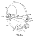
図8A~図8Bを参照すると、本技術の実施形態による、別の例示的なヘッドマウントディスプレイ154が提供される。図8A~図8Bに示したヘッドマウントディスプレイ154は、図2A~図2Bにも示される、ディスプレイモジュール156、ディスプレイブーム158、電源162、カメラ164、及び電子モジュールを含む、ヘッドウェア22のアイテムに装着される。電子モジュール166は、コンピュータプロセッサ、通信コンポーネント、位置追跡コンポーネント、および/または統合構成の他の組みつけられたシステムコンポーネントを含み得る。異なる構成において、電子モジュール166に関連するコンポーネントは、図8A~図8Bに示すように統合されるのではなく、ヘッドマウントディスプレイ154の周りに分散されてもよいことにも留意されたい。
Referring to FIGS. 8A-8B, another exemplary head-mounted
電子モジュール166からディスプレイブーム158を通ってディスプレイモジュール156まで延びる通信ケーブル174が設けられ、ディスプレイモジュール156と電子モジュール166内に配置された1つ以上のコンピュータプロセッサとの間の通信を提供する。また、ヘッドマウントディスプレイ154は、ディスプレイブーム158をヘッドウェア22のアイテムに固定するための取付機構176を含む。取付機構176は、ヘッドウェア22のアイテムの縁部に取り付ける剛性カップリング要素178と、ストラップ180とを含む。ストラップ180は、剛性カップリング要素178と共に、ディスプレイブーム158、電子モジュール166、および電源162をヘッドウェア22に固定するために使用され得る。
A
図8A~図8Bを参照すると、ディスプレイブーム158は、第1の回転可能なカップリング184に取り付けられた第1の端部182と、第2の回転可能なカップリング192に取り付けられた第2の端部190とを含む。第1の回転可能なカップリング184は、ヘッドウェア22の第1の側面188に固定されている取付機構176の第1の剛性カップリング要素186に取り付けられ、第2の回転可能なカップリング192は、ヘッドウェア22の第2の側面196に固定されている第2の剛性カップリング要素194に取り付けられている。
Referring to FIGS. 8A-8B, the
図8A~図8Bに示されるヘッドマウントディスプレイ154のディスプレイブーム158は、ディスプレイモジュールに隣接して取り付けられたコンポーネントモジュール200を含む。コンポーネントモジュール200は、画像および/または映像を撮影するための正面カメラ202(例えば、標準、赤外線、および/または暗視)、ユーザの眼球移動を追跡するための後方カメラ(一例として図16Cを参照)、環境条件を検出するためのさまざまなセンサおよび検出器(例えば温度センサ、空気質センサ、放射線センサなど)、および/または特定の用途のための他の任意のコンポーネントといった、更なるコンポーネントおよび機能を提供してもよい。
The
図9A~図9Bを参照すると、本技術の実施形態による、ディスプレイブーム212に交互に結合された例示的な第1および第2のディスプレイモジュール204、206が提供される。図9Aにおいて、第1の例示的なディスプレイモジュール204は、第1の可動アタッチメント208でディスプレイブーム212に結合されている。図9Aに示される第1のディスプレイモジュール204は、ディスプレイブーム212に対して調節可能である不透明なディスプレイ(例えば、LCD、LEDディスプレイ、OLEDディスプレイ、DLPディスプレイなどのうちの少なくとも1つを含み得るマイクロディスプレイ)を含み、図8A~図8Bに示されるディスプレイブーム158と同様であってもよい。第1のディスプレイモジュール204は、(例えば、ボタン215を押すことによって)第1のディスプレイモジュール204がディスプレイブーム212に対して回転することを可能にするように係合され、(例えば、ボタン215を解放することによって)解除されると、第1のディスプレイモジュール204をディスプレイブーム212に対して固定位置に維持する。
Referring to FIGS. 9A-9B, exemplary first and
図9Bを参照すると、第2の例示的ディスプレイモジュール206は、第2の可動アタッチメント210でディスプレイブーム212に結合されている。第2のディスプレイモジュール206は、透明、部分的透明、および/または選択的透明の光学素子であって、テキスト、画像、および/または他のオブジェクトが、光学部品を通してユーザによって見られるリアルタイム環境と併せて示される拡張現実ディスプレイを提供するように構成され得る光学素子を含む(例えば、光学素子は導波路光学素子であり得る)。第2の可動アタッチメント210は、第2のディスプレイモジュール206がディスプレイブーム212に対していくつかの異なる方向に動くことを可能にする。第2のディスプレイモジュール206は、図9Aに関して説明したように、ロック機構214およびボタン215を使用してディスプレイブーム212に対して固定されてもよい。ロック機構214は使用されてもされなくてもよく、ディスプレイブーム212に対する第1および第2のディスプレイモジュール204、206の位置を保持することは、第1および第2の可動アタッチメント208、210からの摩擦抵抗によって提供されてもよい。
Referring to FIG. 9B, the second
図10を参照すると、本技術の実施形態による、ヘッドウェア218のアイテムに取り付けられた別の例示的なヘッドマウントディスプレイ216が提供される。図10において、ヘッドマウントディスプレイ216は、ディスプレイモジュール220、ディスプレイブーム222、電源224、および電子モジュール226を含み、1つまたは複数のコンピュータプロセッサ、位置追跡コンポーネント、通信コンポーネントなどを、他の可能な又は代替的な子コンポーネントに加えて含み得る。また、電子モジュール226のコンポーネントは、図10のように電子モジュール226に統合されるのではなく、ヘッドマウントディスプレイ216の周りに分配されてもよい。また、ヘッドマウントディスプレイ216は、剛性カップリング要素230およびストラップ234を有する取付機構228と、ヘッドウェア218の縁部232と係合するように構成された剛性カップリング要素230と、剛性カップリング要素230およびヘッドマウントディスプレイ216のコンポーネントを、ヘッドウェア218のまわりに円周方向に固定するように構成されたストラップ234とを含む。
Referring to FIG. 10, another exemplary head-mounted
図10は、ヘッドウェア218の前部にディスプレイモジュール220およびディスプレイブーム222が取り付けられた構成を示す。ヘッドウェア218は、図10では、フルブリムタイプのヘルメットである。また、ディスプレイブーム222は、回転可能なカップリング227で電子モジュール226に結合されており、これにより、ディスプレイモジュール220を、ユーザの顔の正面の第1の位置(図10に示す)と、ユーザの顔から少なくとも部分的に離れている第2の位置とで、上下に回転させることができる。また、ディスプレイモジュール220は、ディスプレイブーム222の第1の側面229から
離れた端部に配置され、追加のコンポーネントモジュール231(例えば、前方および/または後方カメラ、センサ、マイクロフォンなどを含み得る)がディスプレイブーム222に結合されて第2の側面233から離れて配置される。
FIG. 10 shows a configuration in which a
図11を参照すると、本技術の実施形態による、ヘッドマウントディスプレイをヘッドウェア242のアイテムに取り付けるための例示的なハーネスカップリングコンポーネント236が提供される。ハーネスカップリングコンポーネント236は、ヘッドウェア242のアイテムのハーネス構造240に取り付け可能な複数の受容チャネル238を含む。さらに、ハーネスカップリングコンポーネント236は、図2A~図2Bに示されているディスプレイブーム26と同様であり得るディスプレイブーム246(部分的にのみ示されている)に移動可能に結合された基部244に結合されている、。ハーネスカップリングコンポーネント236は、図2A~図2Bに示される取付機構66のコンポーネントなどの、取付機構の他のコンポーネントと併せて使用され得る。
Referring to FIG. 11, an exemplary
図12A~図12Bを参照すると、本技術の一実施形態による、遮音性イヤーカバーアセンブリ250を含む例示的なヘッドマウントディスプレイ248の部分図が提供されている。ヘッドマウントディスプレイおよびヘルメットなどのヘッドウェア用の取付機構に加えて、本明細書の実施形態は、目、耳、顔面、および/または頭の保護などの他の保護および/または実利式な機器と共に使用するように構成され得る。この点に関して、本明細書で説明したヘッドマウントディスプレイは、労働安全衛生法(Occupation Safety and Health Act「OSHA」)のセクション5(a)(1)に概説されているものなどの様々な安全規格を、聴覚保護のためのC.F.R.1910.95、頭部保護のためのC.F.R.1910.135、目と顔の保護のためのC.F.R.1910.33と共に、他の規格に加えて、満たすように構成され得る。
Referring to FIGS. 12A-12B, a partial view of an exemplary head-mounted
図12A~図12Bを参照すると、遮音性イヤーカバーアセンブリ250は、回転可能なカップリング254で互いに移動可能に連結された第1の部分256および第2の部分258を含む。遮音性イヤーカバーアセンブリ250は、レバー260をさらに含み、レバー260は、第1および第2の部分256、258が互いに対して第1の位置251にある図12Aに示す第1の構成262と、第1および第2の部分256、258が互いに対して第2の位置253にある図12Bに示す第2の構成とで、遮音性イヤーカバーアセンブリ250を動かすのに使用することができる(図12Aおよび図12Bに示す位置251、253は単なる例示である)。例示的な実施形態では、レバー260は、第1の部分256、第2の部分258(図12A~図12Bに示すように)、および/または回転可能カップリング254に取り付けられてもよい。第1の構成262では、着用者の耳を実質的に遮音性イヤーカバー内に包囲するように、第2の部分258は、着用者の頭の側面に当接および/または押圧し得る比較的低い位置にあってもよい。第2の構成264では、第2の部分258は、着用者の頭から(第1の構成262に対して)離れる方向に移動して遮音性イヤーカバーアセンブリ250から着用者の耳を完全に露出させることができるように、比較的持ち上げられた位置にある。
Referring to FIGS. 12A-12B, the sound insulating
その結果、図12A~図12Bに示すヘッドマウントディスプレイ248は、第2の部分258を着用者の頭部に対して又は頭部に向かって固定する選択肢を提供し、着用者の耳をより完全に囲むことによってより大きな防音を提供すると共に、レバー260で着用者の頭から離れる方向に第2の部分258を移動させて、相対的に着用者の耳をより完全には覆わないことで低い防音性を提供する。更なる実施形態では、ラッチ、クリップ、ストラップ、および/または他の固定コンポーネントを使用して、第1および第2の部分256、258を第1の位置251および/または第2の位置253、あるいは他の位置に固定してもよい。また、図12A~図12Bに示すヘッドマウントディスプレイ248は、遮音性イヤーカバーアセンブリ250を通じて延びる装着部分272を含む。装着部分
272は、ヘッドマウントディスプレイ248の1つまたは複数のコンポーネント(例えば、1つまたは複数のコンピュータプロセッサおよび/または通信コンポーネント)を一体的に含んでもよい。図14A~図14Bに関してさらに説明されるように、ディスプレイブームを装着するための取付ポイントを提供してもよい。
As a result, the head-mounted
図13A~図13Bを参照すると、本技術の一実施形態による、図12A~図12Bに示す遮音性イヤーカバーアセンブリ250の断面図が示されている。図13Aに示すように、遮音性イヤーカバーアセンブリ250が第1の構成262にあるとき、第2の部分258は相対的に下降した位置にある状態で、第1および第2の部分256、258は第1の位置251にあり、着用者の耳265を少なくとも部分的に覆うことができる。図13Bに示すように、遮音性イヤーカバーアセンブリ250が第2の構成264にあるとき、第2の部分258が少なくとも部分的に着用者の耳265から分離、変位、および/または離れる方向に移動して(すなわち、第1の位置251に対して離れる方向に傾いて)、遮音性イヤーカバーアセンブリ250内から着用者の耳265をより完全に露出させ、それにより、第1の構成262と比べて低い防音性を提供する。
Referring to FIGS. 13A-13B, sectional views of the sound insulating
図14A~図14Bを参照すると、本技術の実施形態による、例示的なディスプレイブームアタッチメントを再び備えた、図12A~図12Bに示したヘッドマウントディスプレイ248が示されている。図14Aでは、回転可能なカップリング270でヘッドマウントディスプレイ248の装着部分272に固定された、第1のディスプレイブーム268が設けられている。第1のディスプレイブーム268は、第1のディスプレイブーム268を回転可能なカップリング270に固定する/取り外すことを可能にする(例えば、他の種類のディスプレイブームと交換するために)取り外し可能なカップリング274をさらに含む。取り外し可能なカップリング274は、図6A~図6Bに示される取り外し可能なカップリング134と同様であり得る。
With reference to FIGS. 14A-14B, the head-mounted
図14Bでは、遮音性イヤーカバーアセンブリ250に固定された第2のディスプレイブーム276が設けられている。第2のディスプレイブーム276は、回転可能なカップリング275で遮音性イヤーカバーアセンブリ250の第2の部分258に移動可能に結合されている。また、第2のディスプレイブーム276は、取り外し可能な連結部278を含み、これは、第2のディスプレイブーム276を遮音性イヤーカバーアセンブリ250に固定する/取り外すことを可能にする図6A~図6Bに示される取り外し可能なカップリング134と同様であり得る。図14A~図14Bに示すディスプレイブーム269、276及びその取付構成は単なる例示であり、他の構成および位置も可能であって想定されることを留意されたい。
In FIG. 14B, a
図15Aを参照すると、本技術の一実施形態による、ディスプレイモジュール284を、図2A~図2Bに示すヘッドマウントディスプレイ20のようなヘッドマウントディスプレイのディスプレイブーム286に取り付けるための第1の取り外し可能なカップリング280が提供されている。図15Aでは、第1の取り外し可能なカップリング280は、雄雌コネクタ292および取り外し機構294を有する機械的カップリングである。取り外し可能なカップリング280は、ディスプレイブーム286の端部に配置された第1の嵌合カップリング288と、ディスプレイモジュール284に配置された第2の嵌合カップリング290とを含む。第1および第2の嵌合カップリング288、290は、ディスプレイモジュール284をディスプレイブーム286に取り付けるために互いに解除可能に固定され得る。さらに、第1の解除可能カップリング280は、図15Aに示す第2の嵌合カップリング290のように構成された別個の嵌合カップリングを有する異なるディスプレイが、ディスプレイモジュール284とは異なる対応ディスプレイ特性を有するディスプレイモジュールを利用するために、第1の嵌合カップリング288に接続されるように構成されてもよい。
Referring to FIG. 15A, a first
図15Bを参照すると、本技術の一実施形態による、ディスプレイモジュール285を、図2A~図2Bに示すヘッドマウントディスプレイ20のようなヘッドマウントディスプレイのディスプレイブーム287に取り付けるための第2の取り外し可能なカップリング282が提供されている。図15Bでは、第2の取り外し可能なカップリング282は磁気式であり、第1の磁気極性を有する第1の嵌合カップリング296と、第1の磁極と反対の第2の磁極を有する第2の嵌合カップリング298とを含み、結果として第1および第2の嵌合カップリング296、298は互いに磁気的に引き付けられる。これにより、ディスプレイモジュール285をディスプレイブーム287に磁気的に取り付けることが可能になる。図15Aに示第1の取り外し可能なカップリング280のように、第2の取り外し可能なカップリング282は、図15Bに示す第2の嵌合カップリング298のように構成された別個の嵌合カップリングを有する異なるディスプレイモジュールが、ディスプレイモジュール285とは異なる対応ディスプレイ特性を有するディスプレイモジュールを利用するために、第1の嵌合カップリング296に接続されるように構成されてもよい。
Referring to FIG. 15B, a second
これに関して、1つのディスプレイモジュールを、異なる対応ディスプレイ特性を有する別のディスプレイモジュールと交換することは、関連するヘッドマウントディスプレイのコンピュータプロセッサが新しいディスプレイ特性に適合することをもたらし得ることに留意されたい。例えば、異なる対応表示特性を有する異なるディスプレイモジュールは、それぞれ、取り外し可能なカップリングでディスプレイモジュールの取り付け時などに、ヘッドマウントディスプレイのプロセッサによって検出されると、プロセッサに適切なドライバをロードさせて、新しいディスプレイモジュールで適切に機能するように視聴出力を再設定するように、ハードウェア識別子および/または埋め込みメタデータを有してもよい。別の例として、ユーザは、ヘッドマウントディスプレイに接続され得る1つ以上のディスプレイモジュール、または現在接続/使用されているディスプレイモジュールに対して適切なドライバおよび/またはディスプレイ構成を手動でロードしてもよい。加えて、ヘッドマウントディスプレイのプロセッサは、ヘッドマウントディスプレイの様々な機能を、取り付けられたディスプレイモジュールにディスプレイモジュールのディスプレイ特性に適合させるように構成された多数のさまざまなドライバおよび/またはアプリケーションをメモリなどに記憶してもよい。 In this regard, it should be noted that replacing one display module with another display module with different corresponding display characteristics may result in the computer processor of the associated head-mounted display adapting to the new display characteristics. For example, different display modules with different corresponding display characteristics, each with a removable coupling, when detected by the processor of the head-mounted display, such as when installing the display module, causes the processor to load the appropriate driver. It may have a hardware identifier and / or embedded metadata to reconfigure the viewing output to function properly with the new display module. As another example, the user may manually load the appropriate driver and / or display configuration for one or more display modules that can be connected to the head-mounted display, or the display module currently connected / used. good. In addition, the processor of the head-mounted display has a large number of different drivers and / or applications that are configured to adapt the various functions of the head-mounted display to the display characteristics of the display module attached to the installed display module, such as memory. You may memorize it in.
図16A~図16Cを参照すると、本技術の実施形態による、異なる対応表示特性を有する様々なディスプレイモジュール300、302、304が提供される。図16Aは、ベース308に結合された第1のディスプレイ部分306を有する第1のディスプレイモジュール300を示している。第1のディスプレイ部分306は、透明、部分的透明、および/または選択的に透明(例えば、画像、文字、および/または拡張現実ディスプレイにおける他の視覚情報を提供するため)であり得る第1の導波路光学素子305を備える。ベース308は、図15Bに示す第2の嵌合カップリング298などの嵌合カップリングを含み、図15Bに示す第1の嵌合カップリング296などの対応嵌合カップリングを含むディスプレイブーム310に交換可能に取り付けることが可能となる。図16Bは、円形の第2の導波路光学素子307を備えて、図16Aに示す第1の導波路光学素子305とは異なる視野を提供する第2のディスプレイモジュール302を示す。第2の導波路光学素子307は、ディスプレイブーム310に取り付けられたベース308に固定される。
Referring to FIGS. 16A-16C,
図16Cは、テキスト、画像、および/または他の対象(例えば白い背景に黒い文字があるPDF)を表示するための不透明なディスプレイ部分312(例えば、LCD、LEDディスプレイ、OLEDディスプレイ、DLPディスプレイなどのうちの少なくとも1つを含み得るマイクロディスプレイ)を含む第3のディスプレイモジュール304を示す
。第3のディスプレイモジュール304は、ディスプレイブーム310に取り付けられ、第3のディスプレイモジュール304を着用しているユーザの眼球移動を追跡するために使用され得る(例えば、書類ナビゲーション用)ユーザ向カメラ314、およびユーザからの音声入力(例えば、音声指令、無線ネットワーク接続を介した通信など)を受けるために使用され得るマイクロフォン316をさらに含む。本開示で説明されるヘッドマウントディスプレイおよびディスプレイモジュールのいずれも、他のコンポーネントおよび機能に加えて、眼球移動を追跡するためのユーザ向けカメラおよび/または音声入力を受けるためのマイクロフォンを含んでもよいことに留意されたい。
FIG. 16C shows an opaque display portion 312 (eg, LCD, LED display, OLED display, DLP display, etc.) for displaying text, images, and / or other objects (eg, PDFs with black text on a white background). A
図17A~図17Bを参照すると、本技術の一実施形態による、第1および第2のディスプレイ部分320、322を有する例示的なディスプレイモジュール318が提供される。第1および第2のディスプレイ部分320、322は互いに固定され、また回転可能なカップリング326でベース324に回転可能に結合される。ベース324はディスプレイブーム328の端部に取り外し可能に取り付けられる。第1および第2のディスプレイ部分320、322は、第1および第2のディスプレイ部分320、322が互いに対して非同一平面上にあるように、ある角度で互いに結合されている。結果として、ユーザの顔の前に配置されたとき、第1および第2のディスプレイ部分320、322は、第1および第2のディスプレイ部分320、322が同一平面上にある場合よりも、それぞれユーザの目に向かってより傾斜したままであり得る。第1および第2のディスプレイ部分320、322の角度は、ユーザのニーズまたは好みに基づいて構成されてもよい。第1のディスプレイ部分320はマイクロディスプレイを含み、第2のディスプレイ部分322は導波路光学素子を含み、ディスプレイモジュール318上に複数の視覚ディスプレイを提供することを可能にする。さらに、ディスプレイモジュール318は、図17Bに示すように、第1および第2のディスプレイ部分320、322を共通の軸330の周りで一体に回転させることによって、起動、停止、および/またはあるいは修正される機能を有してもよい。
Referring to FIGS. 17A-17B, an
図18A~図18Bを参照すると、本技術の一実施形態による、第1および第2のディスプレイ部分334、336を有するディスプレイモジュール332が提供される。図18A-図18Bでは、第1のディスプレイ部分334は不透明(例えば、LCD、LEDディスプレイ、OLEDディスプレイ、DLPディスプレイなどのうちの少なくとも1つを含み得るマイクロディスプレイ)であり、第2のディスプレイ336は、透明、部分的に透明、および/または選択的に透明(例えば、拡張現実ディスプレイを提供するための導波路光学素子)である。第1および第2のディスプレイ部分334、336は、互いに同一平面上にあるように結合され(また、図17A~図17Bに示されるような角度でもあり得る)、そして、取り外し可能なマウント338に取り付けられる。取り外し可能なマウント338は、第1および第2のディスプレイ部分334、336の一方または両方を独立して交換可能とし、ディスプレイモジュール332の表示特性のカスタマイズを可能にする。
Referring to FIGS. 18A-18B, a
図19を参照すると、本技術の一実施形態による、第1および第2のディスプレイ部分344、346を有するディスプレイモジュール342(すなわち、デュアルディスプレイ)が提供される。第1のディスプレイ部分344は不透明(例えば、LCD、LEDディスプレイ、OLEDディスプレイ、DLPディスプレイなどのうちの少なくとも1つを含み得るマイクロディスプレイ)であり、ユーザがある視野角で見るためのテキストを表示しているのが示されており、第2のディスプレイ部分346は、第1のディスプレイ部分344に結合され、少なくとも部分的に透明(例えば、導波路光学素子)であり、第2の視野角でユーザが見た環境と表示された文字/対象348との組み合わせを示している(すなわち、拡張現実ディスプレイ)。拡張現実ディスプレイは、相互関係の情報表示を提供し、関連するヘッドマウントディスプレイの1つまたは複数のコンピュータプロセッ
サから同時に提供される可聴指令と併せて使用され得る。図19では、第2のディスプレイ部分346は、ユーザの視野に対して第1のディスプレイ部分344の上方に位置する。
Referring to FIG. 19, a display module 342 (ie, dual display) with first and
図20A~図20Bを参照すると、本技術の一実施形態による、コモンディスプレイ部352上に複数の表示状態を提供するように構成されたディスプレイモジュール350が提供される。図20A~図20Bに示すディスプレイモジュール350は、不透明である(すなわち、白い背景に黒い文字が提供されている)図20Aに示す第1状態354から、少なくとも部分的に透明である(すなわち、拡張現実ディスプレイ)図20Bに示す第2状態356へと進むように構成されている。この構成により、関連するヘッドマウントディスプレイの使用中に、複数の表示状態(例えば、文書をレビューするためのものと、ユーザが見た実際の環境の文脈の文書からの指令のリアルタイム表示を見るためのもの)を相互に関連付けて見ることができる。
Referring to FIGS. 20A-20B, a
図21を参照すると、本技術の実施形態による、ヘッドマウントディスプレイを調整する例示的な方法2100のブロック図が提供されている。ブロック2110で、図2A~図2Bに示すヘッドマウントディスプレイ20などのヘッドマウントディスプレイが提供される。ヘッドマウントディスプレイは、図2A~図2Bに示される第1の端部44と第2の端部46とのような第1の端部および第2の端部を有する図2A~図2Bに示されるディスプレイブーム26のようなディスプレイブームであって、第2の端部に配置された図2A-図2Bに示すベース28のようなベースに移動可能に結合されるディスプレイブームと、1つまたは複数のコンピュータプロセッサと、電源と、複数の表示状態を提供するように構成された図2A~図2Bに示されるディスプレイモジュール24などの第1のディスプレイモジュールと、図2A~図2Bに示される解除可能なカップリング48などの取り外し可能なカップリングであって、図2A~図2Bに示される第1の嵌合カップリング50などの第1の嵌合カップリングと、図2A~図2Bに示される第2の嵌合カップリング52などの第2の嵌合カップリングと、を有する取り外し可能なカップリングと、を備え得る。第1の嵌合カップリングは、ディスプレイブームの第1の端部に配置されてもよく、第2の嵌合カップリングは、ディスプレイブームの第1のディスプレイモジュールに配置されてもよい。ブロック1120では、第1のディスプレイモジュールは、第1の嵌合カップリングを第2の嵌合カップリングへ固定することによって、ディスプレイブームに取り外し可能に固定される。
Referring to FIG. 21, a block diagram of an
本技術は、あらゆる点で限定的ではなく例示的であることを意図した特定の実施形態に関して説明されてきた。本技術が属する技術分野の当業者には、その範囲から逸脱することなく代替の実施形態が明らかになるであろう。要素の様々な組み合わせ、ならびに図示されていない要素の使用も可能であり、企図されている。
本願発明の実施形態は、例えば、以下の如くである。
[実施形態1]
交換可能なコンポーネントを有するヘッドマウントディスプレイであって、ディスプレイブームは、第1の対応ディスプレイ特性を有する第1のディスプレイモジュールと、第1の端部および第2の端部を備えるディスプレイブームであって、前記第2の端部に配置されたベースに移動可能に結合されたディスプレイブームと、前記第1のディスプレイモジュールに通信可能に結合された1つまたは複数のコンピュータプロセッサと、前記1つまたは複数のコンピュータプロセッサに接続された電源と、第1の嵌合カップリングおよび第2の嵌合カップリングを備える取り外し可能なカップリングであって、前記第1の嵌合カップリングは前記ディスプレイブームの前記第1の端部に配置され、前記第2の嵌合カップリングは前記第1のディスプレイモジュールに配置され、前記第1および第2の篏合カップリングは互いに取り外し可能に固定可能である、ヘッドマウントディスプレイ。
[実施形態2]
前記第1の嵌合カップリングは、第2のディスプレイモジュールの別個の嵌合カップリングに取り外し可能に固定されるように構成され、前記第2のディスプレイモジュールは、前記第1の対応ディスプレイ特性とは異なる第2の対応ディスプレイ特性を有する、実施形態1に記載のヘッドマウントディスプレイ。
[実施形態3]
前記取り外し可能なカップリングは、磁気的カップリングと、第1の固定位置と第2の取り外し位置とで調整可能な機械的カップリングとのうちの少なくとも1つを含む、実施形態1に記載のヘッドマウントディスプレイ。
[実施形態4]
前記ディスプレイブームは、前記ベースに対する前記第1のディスプレイモジュールの関節運動を提供するための少なくとも1つのボールジョイントをさらに備える、実施形態1に記載のヘッドマウントディスプレイ。
[実施形態5]
前記第1のディスプレイモジュールは、第1のディスプレイ部分および第2のディスプレイ部分を提供するデュアルディスプレイを備える、実施形態1に記載のヘッドマウントディスプレイ。
[実施形態6]
前記第1のディスプレイ部分はマイクロディスプレイを備え、前記第2のディスプレイ部分は導波路光学素子を備える、実施形態5に記載のヘッドマウントディスプレイ。
[実施形態7]
前記ディスプレイブームは、第1の位置と第2の位置との間で移動可能であり、前記第1の位置と前記第2の位置との少なくとも一方は、ユーザが設定可能であり、前記ディスプレイブームが前記第1の位置から前記第2の位置に移動すると、前記第1および第2のディスプレイ部分の少なくとも一方が非作動になる、実施形態6に記載のヘッドマウントディスプレイ。
[実施形態8]
前記導波路光学素子は、前記ヘッドマウントディスプレイが着用者の頭に配置されるとき、前記第1のディスプレイモジュールの前記マイクロディスプレイの上に配置される、実施形態6に記載のヘッドマウントディスプレイ。
[実施形態9]
前記導波路光学素子および前記マイクロディスプレイのうちの少なくとも一方は、前記第1のディスプレイモジュールで独立して交換可能である、実施形態6に記載のヘッドマウントディスプレイ。
[実施形態10]
交換可能なコンポーネントを有するヘッドマウントディスプレイであって、第1の対応ディスプレイ特性を有する第1のディスプレイモジュールであって、複数の表示状態を提供するように構成された第1のディスプレイモジュールと、第1の端部および第2の端部を備えるディスプレイブームであって、前記第2の端部に配置されたベースに移動可能に結合されたディスプレイブームと、前記第1のディスプレイモジュールに通信可能に結合された1つまたは複数のコンピュータプロセッサと、前記1つまたは複数のコンピュータプロセッサに接続された電源と、第1の篏合カップリングおよび第2の篏合カップリングを備える取り外し可能なカップリングであって、前記第1の篏合カップリングは前記ディスプレイブームの前記第1の端部に配置され、前記第2の篏合カップリングは前記第1のディスプレイモジュールに配置され、前記第1および第2の篏合カップリングは互いに取り外し可能に固定可能である、ヘッドマウントディスプレイ。
[実施形態11]
前記第1の嵌合カップリングは、第2のディスプレイモジュールの別個の嵌合カップリングに取り外し可能に固定されるように構成され、前記第2のディスプレイモジュールは、前記第1の対応ディスプレイ特性とは異なる第2の対応ディスプレイ特性を有する、実施形態10に記載のヘッドマウントディスプレイ。
[実施形態12]
前記第1のディスプレイモジュールは、第1のディスプレイ部分と第2のディスプレイ部分とを備え、前記第1のディスプレイ部分はマイクロディスプレイを備え、前記第2のディスプレイ部分は導波路光学素子を備える、実施形態10に記載のヘッドマウントディスプレイ。
[実施形態13]
前記第1のディスプレイ部分および前記第2のディスプレイ部分は、前記第1および第2のディスプレイ部分が同一平面上とならない角度で結合される、実施形態12に記載のヘッドマウントディスプレイ。
[実施形態14]
前記取り外し可能なカップリングは、磁気的カップリングと、第1の固定位置と第2の取り外し位置とで移動可能な機械的カップリングとのうちの少なくとも1つを含む、実施形態10に記載のヘッドマウントディスプレイ。
[実施形態15]
前記第1のディスプレイモジュールは、第1のディスプレイ状態と第2のディスプレイ状態とで調整可能であることにより前記複数の表示状態を提供し、前記第1のディスプレイ状態は非透明状態を含み、前記第2のディスプレイは、少なくとも部分的に透明な状態を含む、実施形態10に記載のヘッドマウントディスプレイ。
[実施形態16]
ヘッドマウントディスプレイを調整する方法であって、第1の端部および第2の端部を有するディスプレイブームであって、前記第2の端部に位置するベースに移動可能に結合されたディスプレイブームと、1つまたは複数のコンピュータプロセッサと、電源と、複数の表示状態を提供するように構成された第1のディスプレイモジュールと、第1の嵌合カップリングおよび第2の嵌合カップリングを備える取り外し可能なカップリングであって、前記第1の篏合カップリングが前記ディスプレイブームの前記第1の端部に配置され、前記第2の篏合カップリングが前記第1のディスプレイモジュールに配置される、取り外し可能なカップリングと、を備えるヘッドマウントディスプレイを提供することと、前記第1の嵌合カップリングを前記第2の嵌合カップリングに固定することによって前記第1のディスプレイモジュールを前記ディスプレイブームに取り外し可能に固定することと、を含む方法。
[実施形態17]
前記複数の表示状態は、第1のディスプレイ状態を提供する第1のディスプレイ部分と、第2のディスプレイ状態を提供する第2のディスプレイ部分と、のうちの少なくとも1つで構成される前記第1のディスプレイモジュールと、前記第1のディスプレイ状態と前記第2のディスプレイ状態とを交換可能に提供するコモンディスプレイ部分と、を通じて提供され、前記第1のディスプレイ状態は非透明状態を含み、前記第2のディスプレイ状態は少なくとも部分的に透明な状態を含む、実施形態16に記載の方法。
[実施形態18]
前記第1のディスプレイ部分と前記第2のディスプレイ部分とを共通の軸まわりに回転させることにより、前記第1のディスプレイ状態と前記第2のディスプレイ状態とを切り替えること、または前記コモンディスプレイを前記第1のディスプレイ状態と前記第2のディスプレイ状態とで切り替えること、をさらに含む、実施形態17に記載の方法。
[実施形態19]
前記第2のディスプレイ状態は、拡張現実ディスプレイを含む、実施形態17に記載の方法。
[実施形態20]
前記第1および第2の嵌合カップリングを互いに切り離して前記第1のディスプレイモジュールを前記ディスプレイブームから切り離すことと、第2ディスプレイモジュールの別個の嵌合カップリングを前記第1の嵌合カップリングに結合して前記第2のディスプレイモジュールを前記ディスプレイブームに取り外し可能に固定することと、をさらに含み、前記第1および第2のディスプレイモジュールは、異なる対応ディスプレイ特性を有する、実施形態16に記載の方法。
The art has been described with respect to specific embodiments intended to be exemplary rather than limiting in all respects. Those skilled in the art to which this technique belongs will be able to identify alternative embodiments without departing from that scope. Various combinations of elements, as well as the use of elements not shown, are also possible and contemplated.
An embodiment of the present invention is, for example, as follows.
[Embodiment 1]
A head-mounted display with replaceable components, the display boom is a display boom with a first display module having a first corresponding display characteristic and a first end and a second end. A display boom movably coupled to a base located at the second end, one or more computer processors communicably coupled to the first display module, and the one or more. A removable coupling comprising a power source connected to a computer processor and a first mating coupling and a second mating coupling, wherein the first mating coupling is said to the display boom. A head that is located at the first end, the second mating coupling is located in the first display module, and the first and second mating couplings are removable and secure to each other. Mount display.
[Embodiment 2]
The first mating coupling is configured to be removably secured to a separate mating coupling of the second display module, the second display module with said first corresponding display characteristics. The head-mounted display according to the first embodiment, which has a different second corresponding display characteristic.
[Embodiment 3]
The removable coupling according to embodiment 1, wherein the removable coupling comprises at least one of a magnetic coupling and a mechanical coupling adjustable between a first fixed position and a second removable position. Head-mounted display.
[Embodiment 4]
The head-mounted display according to embodiment 1, wherein the display boom further comprises at least one ball joint for providing joint movement of the first display module with respect to the base.
[Embodiment 5]
The head-mounted display according to the first embodiment, wherein the first display module includes a dual display that provides a first display portion and a second display portion.
[Embodiment 6]
The head-mounted display according to the fifth embodiment, wherein the first display portion includes a micro display, and the second display portion includes a waveguide optical element.
[Embodiment 7]
The display boom is movable between a first position and a second position, and at least one of the first position and the second position is user configurable and the display boom. The head-mounted display according to the sixth embodiment, wherein when the head-mounted display moves from the first position to the second position, at least one of the first and second display portions becomes inoperable.
[Embodiment 8]
The head-mounted display according to
[Embodiment 9]
The head-mounted display according to
[Embodiment 10]
A head-mounted display with interchangeable components, a first display module with first corresponding display characteristics, a first display module configured to provide a plurality of display states, and a first. A display boom comprising one end and a second end, capable of communicating with the first display module with a display boom movably coupled to a base located at the second end. With one or more combined computer processors, a power supply connected to said one or more computer processors, and a removable coupling with a first and second combined coupling. The first combined coupling is located at the first end of the display boom and the second combined coupling is located at the first display module, the first and the first. A head-mounted display in which the two couplings are removable and secure to each other.
[Embodiment 11]
The first mating coupling is configured to be removably secured to a separate mating coupling of the second display module, the second display module with said first corresponding display characteristics. The head-mounted display according to
[Embodiment 12]
The first display module includes a first display portion and a second display portion, the first display portion includes a micro display, and the second display portion includes a waveguide optical element. The head-mounted display according to the tenth embodiment.
[Embodiment 13]
12. The head-mounted display according to the twelfth embodiment, wherein the first display portion and the second display portion are coupled at an angle so that the first and second display portions are not coplanar.
[Embodiment 14]
10. The detachable coupling according to
[Embodiment 15]
The first display module provides the plurality of display states by being adjustable between the first display state and the second display state, and the first display state includes a non-transparent state. The second display is the head-mounted display according to the tenth embodiment, which comprises at least a partially transparent state.
[Embodiment 16]
A method of adjusting a head-mounted display, the display boom having a first end and a second end, with a display boom movably coupled to a base located at the second end. Detachment with one or more computer processors, a power supply, a first display module configured to provide multiple display states, and a first mating coupling and a second mating coupling. A possible coupling, wherein the first integrated coupling is placed at the first end of the display boom and the second combined coupling is placed at the first display module. The first display module is attached to the display by providing a head mount display comprising a removable coupling and fixing the first mating coupling to the second mating coupling. Detachable fixing to the boom and methods including.
[Embodiment 17]
The first display state is composed of at least one of a first display portion that provides a first display state and a second display portion that provides a second display state. Provided through a display module and a common display portion that interchangeably provides the first display state and the second display state, wherein the first display state includes a non-transparent state and the second display state. 16. The method of
[Embodiment 18]
Switching between the first display state and the second display state by rotating the first display portion and the second display portion around a common axis, or using the common display as the first display. The method according to embodiment 17, further comprising switching between the display state of 1 and the second display state.
[Embodiment 19]
The method of embodiment 17, wherein the second display state comprises an augmented reality display.
[Embodiment 20]
The first and second fitting couplings are separated from each other to separate the first display module from the display boom, and the separate fitting couplings of the second display module are separated from the first fitting coupling. 16. The first and second display modules have different corresponding display characteristics, further comprising coupling to and detachably fixing the second display module to the display boom. the method of.
Claims (11)
前記ヘッドマウントディスプレイの本体に収容され、それに結合されたときに交換可能なディスプレイモジュールのセットの1つに視覚データを表示するように動作可能な1つ又は複数のコンピュータプロセッサと、
ディスプレイブームであって、
前記本体に調整可能に結合された第1の端部と、
第2の端部であって、
前記1つ又は複数のコンピュータプロセッサに結合された少なくとも第1のインターフェースを提示する第1のカップリング部材と、
前記交換可能なディスプレイモジュールのセットの1つを、結合されているときに前記ディスプレイブームの前記第2の端部から切り離すように動作可能な解放機構と、
を有する第2の端部と、
を有するディスプレイブームと、
前記交換可能なディスプレイモジュールのセットからの第1の交換可能なディスプレイモジュールであって、
第1のディスプレイと、
前記第1のカップリング部材を補完する第2のカップリング部材であって、前記第2のカップリング部材は、前記第1のディスプレイに結合された少なくとも第2のインターフェースを提示する、第2のカップリング部材と、
を有する第1の交換可能なディスプレイモジュールと、備え、
少なくとも前記第1および第2のインターフェースは、前記第1のカップリング部材が前記第2のカップリング部材に取り外し可能に固定されるとき、前記第1の交換可能なディスプレイモジュールを前記1つ又は複数のコンピュータプロセッサに通信可能に結合するように適合され、
前記第1のカップリング部材と前記第2のカップリング部材とは、互いに取り外し可能に固定されると、前記ディスプレイブームの前記第2の端部と前記第1の交換可能なディスプレイモジュールの端部との間にエンドツーエンド接続を提供する、
モジュール式ヘッドマウントディスプレイ。 It's a modular head-mounted display
With one or more computer processors housed in the body of the head-mounted display and capable of operating to display visual data on one of a set of interchangeable display modules when coupled to it.
It ’s a display boom,
With a first end tunably coupled to the body,
The second end,
A first coupling member presenting at least a first interface coupled to the one or more computer processors.
With a release mechanism that can operate to disconnect one of the set of interchangeable display modules from the second end of the display boom when coupled.
With a second end,
With display boom,
A first replaceable display module from the set of replaceable display modules.
The first display and
A second coupling member that complements the first coupling member, wherein the second coupling member presents at least a second interface coupled to the first display. Coupling member and
With a first replaceable display module,
At least the first and second interfaces may include one or more of the first replaceable display modules when the first coupling member is detachably secured to the second coupling member. Fitted to communicatively coupled to a computer processor
When the first coupling member and the second coupling member are detachably fixed to each other, the second end of the display boom and the end of the first replaceable display module. Provides an end-to-end connection with,
Modular head-mounted display.
1つ又は複数のコンピュータプロセッサを備える取付部分と、
ディスプレイブームであって、
第1の端部と、
第2の端部と、を備え、
前記第1の端部は、第1のカップリング部材と、前記1つ又は複数のコンピュータプロセッサに通信可能に接続された第1のインターフェースとを備え、
前記第2の端部は、前記取付部分に移動可能に結合される、ディスプレイブームと、
ディスプレイモジュールであって、
ディスプレイ部分と、
前記第1のカップリング部材を補完する第2のカップリング部材と、
前記ディスプレイ部分に通信可能に接続された第2のインターフェースと、を備えるディスプレイモジュールと、
を備え、
前記第1のカップリング部材と前記第2のカップリング部材とが互いに解放可能に結合されると、前記ディスプレイブームの前記第1の端部と前記ディスプレイモジュールの端部との間にエンドツーエンド接続が形成され、前記第2のインターフェースが前記第1ののインターフェースに接続される、
モジュール式ヘッドマウントディスプレイ。 It's a modular head-mounted display
Mounting parts with one or more computer processors,
It ’s a display boom,
The first end and
With a second end,
The first end comprises a first coupling member and a first interface communicably connected to the one or more computer processors.
The second end is movably coupled to the mounting portion with a display boom.
It ’s a display module.
The display part and
A second coupling member that complements the first coupling member,
A display module comprising a second interface communicably connected to the display portion,
Equipped with
When the first coupling member and the second coupling member are releasably coupled to each other, end-to-end between the first end of the display boom and the end of the display module. A connection is formed and the second interface is connected to the first interface.
Modular head-mounted display.
Applications Claiming Priority (3)
| Application Number | Priority Date | Filing Date | Title |
|---|---|---|---|
| US15/390,363 | 2016-12-23 | ||
| US15/390,363 US10437070B2 (en) | 2016-12-23 | 2016-12-23 | Interchangeable optics for a head-mounted display |
| PCT/US2017/064898 WO2018118432A1 (en) | 2016-12-23 | 2017-12-06 | Interchangeable optics for a head-mounted display |
Publications (3)
| Publication Number | Publication Date |
|---|---|
| JP2020504988A JP2020504988A (en) | 2020-02-13 |
| JP2020504988A5 JP2020504988A5 (en) | 2021-01-21 |
| JP7012744B2 true JP7012744B2 (en) | 2022-01-28 |
Family
ID=62627127
Family Applications (1)
| Application Number | Title | Priority Date | Filing Date |
|---|---|---|---|
| JP2019555414A Active JP7012744B2 (en) | 2016-12-23 | 2017-12-06 | Module component for head-mounted display |
Country Status (5)
| Country | Link |
|---|---|
| US (2) | US10437070B2 (en) |
| EP (1) | EP3559729A4 (en) |
| JP (1) | JP7012744B2 (en) |
| CN (1) | CN110249254B (en) |
| WO (1) | WO2018118432A1 (en) |
Families Citing this family (19)
| Publication number | Priority date | Publication date | Assignee | Title |
|---|---|---|---|---|
| US10437070B2 (en) * | 2016-12-23 | 2019-10-08 | Realwear, Inc. | Interchangeable optics for a head-mounted display |
| US20190008228A1 (en) * | 2016-12-30 | 2019-01-10 | David Francis Ramey | Integrated non-conflicting headgear platform system and method |
| EP3363312B1 (en) * | 2017-02-17 | 2020-10-28 | Savox Communications Oy AB (LTD) | Adaptable mounting system for mounting one or more accessory devices to a helmet |
| US10928163B2 (en) * | 2017-10-04 | 2021-02-23 | Trent Zimmer | Ballistic helmet |
| US20200137336A1 (en) * | 2018-10-30 | 2020-04-30 | Bae Systems Information And Electronic Systems Integration Inc. | Interlace image sensor for low-light-level imaging |
| CN109581665A (en) * | 2019-01-02 | 2019-04-05 | 京东方科技集团股份有限公司 | A kind of display device and its display methods, wear-type virtual display device |
| US11857378B1 (en) * | 2019-02-14 | 2024-01-02 | Onpoint Medical, Inc. | Systems for adjusting and tracking head mounted displays during surgery including with surgical helmets |
| GB201903152D0 (en) * | 2019-03-08 | 2019-04-24 | Dimensional Imaging Ltd | Helmet |
| CN113574909A (en) * | 2019-04-16 | 2021-10-29 | 德姆福特游乐有限公司 | Split head-mounted device with audio for Augmented Reality (AR) or Virtual Reality (VR) or Mixed Reality (MR) |
| US20210000650A1 (en) * | 2019-07-01 | 2021-01-07 | Focus Labs, LLC | Event-triggered eye occlusion |
| US11733529B1 (en) * | 2020-04-21 | 2023-08-22 | Apple Inc. | Load-distributing headband for head-mounted device |
| WO2021234832A1 (en) * | 2020-05-20 | 2021-11-25 | ヤマハ発動機株式会社 | Eye tracking device |
| WO2021240468A2 (en) * | 2020-05-29 | 2021-12-02 | Vrmedia S.R.L. | System for augmented reality |
| USD968401S1 (en) | 2020-06-17 | 2022-11-01 | Focus Labs, LLC | Device for event-triggered eye occlusion |
| US11906748B1 (en) * | 2020-09-01 | 2024-02-20 | Apple Inc. | Support for head-mountable device |
| AU2022232312A1 (en) * | 2021-03-12 | 2023-08-24 | Milwaukee Electric Tool Corporation | Safety headwear systems and accessories |
| CN117320585A (en) * | 2021-05-13 | 2023-12-29 | 北极星工业有限公司 | System and method for smart helmets |
| CN113805659A (en) * | 2021-09-17 | 2021-12-17 | 瑞欧威尔(上海)智能科技有限公司 | Head-mounted display device with live broadcast function |
| CN114236853B (en) * | 2022-01-26 | 2024-01-05 | 中煤科工开采研究院有限公司 | Split type mining AR glasses fixing device and using method thereof |
Citations (2)
| Publication number | Priority date | Publication date | Assignee | Title |
|---|---|---|---|---|
| US20110090135A1 (en) | 2009-10-21 | 2011-04-21 | Symbol Technologies, Inc. | Interchangeable display device for a head-mounted display system |
| US20120002046A1 (en) | 2010-06-30 | 2012-01-05 | Raytheon Company | Flip-Up Hands-Free Display Mount |
Family Cites Families (217)
| Publication number | Priority date | Publication date | Assignee | Title |
|---|---|---|---|---|
| SE8703414L (en) | 1987-09-02 | 1989-03-03 | Kompositprodukter Sk Fm Ab | HOERSELSKYDD |
| US5046192A (en) | 1989-09-26 | 1991-09-10 | Ryder International Corporation | Headset sun visor |
| US5185807A (en) | 1991-05-08 | 1993-02-09 | David Clark Company Incorporated | Headset with multi-position stirrup assemblies |
| JP3163701B2 (en) | 1991-12-27 | 2001-05-08 | ソニー株式会社 | Glasses-type image display device |
| DE69434843T2 (en) | 1993-08-12 | 2007-02-15 | Seiko Epson Corp. | Head-mounted image display device and data processing system incorporating the same |
| US6061064A (en) | 1993-08-31 | 2000-05-09 | Sun Microsystems, Inc. | System and method for providing and using a computer user interface with a view space having discrete portions |
| US5815126A (en) | 1993-10-22 | 1998-09-29 | Kopin Corporation | Monocular portable communication and display system |
| US5806079A (en) | 1993-11-19 | 1998-09-08 | Smartpatents, Inc. | System, method, and computer program product for using intelligent notes to organize, link, and manipulate disparate data objects |
| US6587700B1 (en) * | 1994-06-23 | 2003-07-01 | At&T Wireless Services, Inc. | Personal communicator with flip element display |
| US6198462B1 (en) | 1994-10-14 | 2001-03-06 | Hughes Electronics Corporation | Virtual display screen system |
| US5767820A (en) | 1995-05-09 | 1998-06-16 | Virtual Research Systems | Head-mounted visual display apparatus |
| US7453451B1 (en) | 1999-03-16 | 2008-11-18 | Maguire Francis J Jr | Moveable headrest for viewing images from different directions |
| JPH09130705A (en) | 1995-10-31 | 1997-05-16 | Olympus Optical Co Ltd | Head mounted video display device |
| US5796374A (en) * | 1996-03-08 | 1998-08-18 | Virtual Vision, Inc. | Support for a head mounted display system |
| DE19625351C1 (en) | 1996-06-25 | 1997-11-20 | Lemfoerder Metallwaren Ag | Process for producing a low-friction ball joint, as well as low-friction ball joint |
| US5850211A (en) | 1996-06-26 | 1998-12-15 | Sun Microsystems, Inc. | Eyetrack-driven scrolling |
| US6204974B1 (en) * | 1996-10-08 | 2001-03-20 | The Microoptical Corporation | Compact image display system for eyeglasses or other head-borne frames |
| US6754361B1 (en) | 1997-04-17 | 2004-06-22 | 3M Innovative Properties Company | Ergonomic headset assembly |
| US7121946B2 (en) | 1998-08-10 | 2006-10-17 | Cybernet Systems Corporation | Real-time head tracking system for computer games and other applications |
| DE19839461C1 (en) | 1998-08-29 | 1999-11-04 | Flm Gmbh Foto Licht Und Mestec | Stative head for camera |
| US6867752B1 (en) | 1998-08-31 | 2005-03-15 | Semiconductor Energy Laboratory Co., Ltd. | Portable information processing system |
| US6434250B1 (en) | 1999-03-05 | 2002-08-13 | Parker I. Tsuhako | Stereo headset with angled speakers |
| US7124425B1 (en) | 1999-03-08 | 2006-10-17 | Immersion Entertainment, L.L.C. | Audio/video system and method utilizing a head mounted apparatus with noise attenuation |
| WO2000055673A1 (en) | 1999-03-17 | 2000-09-21 | Colorado Microdisplay, Inc. | Headset boom for image display module |
| US6222677B1 (en) * | 1999-04-12 | 2001-04-24 | International Business Machines Corporation | Compact optical system for use in virtual display applications |
| US6466198B1 (en) | 1999-11-05 | 2002-10-15 | Innoventions, Inc. | View navigation and magnification of a hand-held device with a display |
| US6456262B1 (en) | 2000-05-09 | 2002-09-24 | Intel Corporation | Microdisplay with eye gaze detection |
| ES2258972T3 (en) | 2000-05-16 | 2006-09-16 | Swisscom Mobile Ag | PROCEDURE AND TERMINAL TO ENTER INSTRUCTIONS. |
| US6747611B1 (en) * | 2000-07-27 | 2004-06-08 | International Business Machines Corporation | Compact optical system and packaging for head mounted display |
| US20020044152A1 (en) | 2000-10-16 | 2002-04-18 | Abbott Kenneth H. | Dynamic integration of computer generated and real world images |
| US6774869B2 (en) * | 2000-12-22 | 2004-08-10 | Board Of Trustees Operating Michigan State University | Teleportal face-to-face system |
| FI20010958A0 (en) | 2001-05-08 | 2001-05-08 | Nokia Corp | Procedure and Arrangements for Designing an Extended User Interface |
| GB2377147A (en) | 2001-06-27 | 2002-12-31 | Nokia Corp | A virtual reality user interface |
| AR035939A1 (en) | 2002-03-04 | 2004-07-28 | Rolla Jose Maria | IMPROVEMENTS IN FOLDING HEADPHONES |
| US6941521B2 (en) | 2002-03-29 | 2005-09-06 | Intel Corporation | Method for dynamically generating a user interface from XML-based documents |
| US7353464B1 (en) | 2002-04-01 | 2008-04-01 | Microsoft Corporation | Hierarchical data navigation tool populated by a web service |
| TW594658B (en) * | 2002-07-01 | 2004-06-21 | Leadtek Research Inc | Helmet-mounted display |
| JP3843951B2 (en) | 2003-02-13 | 2006-11-08 | 株式会社ニコン | Image display device |
| US6637883B1 (en) | 2003-01-23 | 2003-10-28 | Vishwas V. Tengshe | Gaze tracking system and method |
| ITMI20030121A1 (en) * | 2003-01-27 | 2004-07-28 | Giuseppe Donato | MODULAR SURVEILLANCE SYSTEM FOR MONITORING OF CRITICAL ENVIRONMENTS. |
| US6708339B1 (en) | 2003-04-22 | 2004-03-23 | James Smith, Jr. | Sport helmet face guard |
| EP1472944B1 (en) | 2003-05-02 | 2009-06-17 | Jose Maria Rolla | Ear protector for helmet and helmet including said ear protector |
| JP2004363718A (en) | 2003-06-02 | 2004-12-24 | Sanyo Electric Co Ltd | Antenna system |
| US7389235B2 (en) | 2003-09-30 | 2008-06-17 | Motorola, Inc. | Method and system for unified speech and graphic user interfaces |
| EP1688014A4 (en) | 2003-11-13 | 2009-07-22 | Logitech Europ Sa | Behind-the-head mounted personal audio set |
| US7190330B2 (en) * | 2004-01-07 | 2007-03-13 | Icuiti Corporation | Virtual display headset |
| KR100800859B1 (en) | 2004-08-27 | 2008-02-04 | 삼성전자주식회사 | Apparatus and method for inputting key in head mounted display information terminal |
| US7519923B2 (en) | 2004-10-20 | 2009-04-14 | International Business Machines Corporation | Method for generating a tree view of elements in a graphical user interface (GUI) |
| CN101156104A (en) | 2005-02-11 | 2008-04-02 | 奥克利有限公司 | Eyeglasses with detachable adjustable electronics module |
| JP4572737B2 (en) | 2005-05-10 | 2010-11-04 | 株式会社島津製作所 | Head mounted display |
| US20060256090A1 (en) | 2005-05-12 | 2006-11-16 | Apple Computer, Inc. | Mechanical overlay |
| CN1293446C (en) | 2005-06-02 | 2007-01-03 | 北京中星微电子有限公司 | Non-contact type visual control operation system and method |
| JP4828181B2 (en) | 2005-08-29 | 2011-11-30 | 三菱電機株式会社 | Head mounted image display device |
| US20070052672A1 (en) | 2005-09-08 | 2007-03-08 | Swisscom Mobile Ag | Communication device, system and method |
| US20070130547A1 (en) | 2005-12-01 | 2007-06-07 | Navisense, Llc | Method and system for touchless user interface control |
| JP4957177B2 (en) * | 2006-01-20 | 2012-06-20 | 株式会社デンソー | Display device |
| US7773767B2 (en) | 2006-02-06 | 2010-08-10 | Vocollect, Inc. | Headset terminal with rear stability strap |
| US8793620B2 (en) | 2011-04-21 | 2014-07-29 | Sony Computer Entertainment Inc. | Gaze-assisted computer interface |
| US8334841B2 (en) | 2006-03-13 | 2012-12-18 | Navisense | Virtual user interface method and system thereof |
| US20070220108A1 (en) | 2006-03-15 | 2007-09-20 | Whitaker Jerry M | Mobile global virtual browser with heads-up display for browsing and interacting with the World Wide Web |
| US7928926B2 (en) | 2006-06-27 | 2011-04-19 | Panasonic Corporation | Display apparatus and method for hands free operation that selects a function when window is within field of view |
| US8564544B2 (en) | 2006-09-06 | 2013-10-22 | Apple Inc. | Touch screen device, method, and graphical user interface for customizing display of content category icons |
| US7613292B2 (en) | 2006-09-29 | 2009-11-03 | Sony Ericsson Mobile Communications Ab | Adjustable earpiece |
| US20170017464A1 (en) | 2006-11-03 | 2017-01-19 | Philippe Roy | Layered contextual configuration management system and method and minimized input speech recognition user interface interactions experience |
| JP5190070B2 (en) | 2007-01-12 | 2013-04-24 | コピン コーポレーション | Monocular display device |
| US8855719B2 (en) * | 2009-05-08 | 2014-10-07 | Kopin Corporation | Wireless hands-free computing headset with detachable accessories controllable by motion, body gesture and/or vocal commands |
| US7722358B2 (en) * | 2007-06-15 | 2010-05-25 | Microsoft Corporation | Electrical connection between devices |
| US7962344B2 (en) | 2007-06-29 | 2011-06-14 | Microsoft Corporation | Depicting a speech user interface via graphical elements |
| JP2009033308A (en) | 2007-07-25 | 2009-02-12 | Nikon Corp | Head-mounted display |
| US8825468B2 (en) * | 2007-07-31 | 2014-09-02 | Kopin Corporation | Mobile wireless display providing speech to speech translation and avatar simulating human attributes |
| FR2921991B1 (en) | 2007-10-09 | 2011-05-06 | Skf Aerospace France | LIGHT JOINT ROD AND METHOD OF MANUFACTURING THE SAME |
| US20090100732A1 (en) * | 2007-10-19 | 2009-04-23 | Concept Workshop Worldwide, Llc | Magnetic display device |
| US8072393B2 (en) | 2007-11-15 | 2011-12-06 | Symbol Technologies, Inc. | User interface for a head mounted display |
| US20100259471A1 (en) | 2007-11-16 | 2010-10-14 | Nikon Corporation | Control device, head-mount display device, program, and control method |
| US20090182562A1 (en) | 2008-01-14 | 2009-07-16 | Garmin Ltd. | Dynamic user interface for automated speech recognition |
| IL189251A0 (en) | 2008-02-05 | 2008-11-03 | Ehud Gal | A manned mobile platforms interactive virtual window vision system |
| US8321226B2 (en) | 2008-08-08 | 2012-11-27 | Hewlett-Packard Development Company, L.P. | Generating speech-enabled user interfaces |
| US8706685B1 (en) | 2008-10-29 | 2014-04-22 | Amazon Technologies, Inc. | Organizing collaborative annotations |
| US8594467B2 (en) | 2008-12-19 | 2013-11-26 | Microsoft Corporation | Interactive virtual display system for ubiquitous devices |
| CN102460349A (en) | 2009-05-08 | 2012-05-16 | 寇平公司 | Remote control of host application using motion and voice commands |
| US20100315329A1 (en) | 2009-06-12 | 2010-12-16 | Southwest Research Institute | Wearable workspace |
| US20130169514A1 (en) | 2009-06-25 | 2013-07-04 | The Boeing Company | Method and apparatus for a virtual mission control station |
| US8773330B2 (en) | 2009-06-25 | 2014-07-08 | The Boeing Company | Method and apparatus for a virtual mission control station |
| CN101950866B (en) * | 2009-07-10 | 2014-03-05 | 深圳富泰宏精密工业有限公司 | Elastic sheet structure and electronic device applying same |
| JP5263049B2 (en) | 2009-07-21 | 2013-08-14 | ソニー株式会社 | Information processing apparatus, information processing method, and program |
| US20120272484A1 (en) | 2009-10-02 | 2012-11-01 | Willborn Inventstments Incorporated | Multiposition visor adaptor system |
| US9292084B2 (en) | 2009-10-13 | 2016-03-22 | Intel Corporation | Control systems and methods for head-mounted information systems |
| CN101673161B (en) | 2009-10-15 | 2011-12-07 | 复旦大学 | Visual, operable and non-solid touch screen system |
| US20110096036A1 (en) | 2009-10-23 | 2011-04-28 | Mcintosh Jason | Method and device for an acoustic sensor switch |
| JP2011169449A (en) | 2010-02-22 | 2011-09-01 | Jtekt Corp | Ball joint |
| US20150309316A1 (en) | 2011-04-06 | 2015-10-29 | Microsoft Technology Licensing, Llc | Ar glasses with predictive control of external device based on event input |
| US8908043B2 (en) * | 2010-04-12 | 2014-12-09 | Symbol Technologies, Inc. | System and method for location-based operation of a head mounted display |
| US8531355B2 (en) | 2010-07-23 | 2013-09-10 | Gregory A. Maltz | Unitized, vision-controlled, wireless eyeglass transceiver |
| US9916006B2 (en) | 2010-07-23 | 2018-03-13 | Telepatheye Inc. | Eye-wearable device user interface and method |
| US9111498B2 (en) | 2010-08-25 | 2015-08-18 | Eastman Kodak Company | Head-mounted display with environmental state detection |
| US8619005B2 (en) | 2010-09-09 | 2013-12-31 | Eastman Kodak Company | Switchable head-mounted display transition |
| US9316827B2 (en) | 2010-09-20 | 2016-04-19 | Kopin Corporation | LifeBoard—series of home pages for head mounted displays (HMD) that respond to head tracking |
| US8736516B2 (en) | 2010-09-20 | 2014-05-27 | Kopin Corporation | Bluetooth or other wireless interface with power management for head mounted display |
| US8706170B2 (en) | 2010-09-20 | 2014-04-22 | Kopin Corporation | Miniature communications gateway for head mounted display |
| US9122307B2 (en) | 2010-09-20 | 2015-09-01 | Kopin Corporation | Advanced remote control of host application using motion and voice commands |
| US9377862B2 (en) | 2010-09-20 | 2016-06-28 | Kopin Corporation | Searchlight navigation using headtracker to reveal hidden or extra document data |
| US10013976B2 (en) | 2010-09-20 | 2018-07-03 | Kopin Corporation | Context sensitive overlays in voice controlled headset computer displays |
| US10036891B2 (en) * | 2010-10-12 | 2018-07-31 | DISH Technologies L.L.C. | Variable transparency heads up displays |
| US8994610B2 (en) | 2010-11-08 | 2015-03-31 | Symbol Technologies, Inc. | User configurable headset |
| KR20120063982A (en) | 2010-12-08 | 2012-06-18 | 한국전자통신연구원 | Apparatus and method of man-machine interface for invisible user |
| US10365819B2 (en) | 2011-01-24 | 2019-07-30 | Apple Inc. | Device, method, and graphical user interface for displaying a character input user interface |
| KR101372123B1 (en) * | 2011-03-31 | 2014-03-07 | 파나소닉 주식회사 | Resin composition for optical waveguide, dry film, optical waveguide, and photoelectric composite wiring board using same |
| WO2012154938A1 (en) * | 2011-05-10 | 2012-11-15 | Kopin Corporation | Headset computer that uses motion and voice commands to control information display and remote devices |
| US20130007672A1 (en) | 2011-06-28 | 2013-01-03 | Google Inc. | Methods and Systems for Correlating Head Movement with Items Displayed on a User Interface |
| US8631371B2 (en) | 2011-06-29 | 2014-01-14 | International Business Machines Corporation | Method, system and program storage device for modeling the capacitance associated with a diffusion region of a silicon-on-insulator device |
| US20130018659A1 (en) | 2011-07-12 | 2013-01-17 | Google Inc. | Systems and Methods for Speech Command Processing |
| US20130021269A1 (en) | 2011-07-20 | 2013-01-24 | Google Inc. | Dynamic Control of an Active Input Region of a User Interface |
| WO2013014709A1 (en) | 2011-07-27 | 2013-01-31 | 三菱電機株式会社 | User interface device, onboard information device, information processing method, and information processing program |
| US8996510B2 (en) | 2011-08-23 | 2015-03-31 | Buckyball Mobile, Inc. | Identifying digital content using bioresponse data |
| US9168176B2 (en) | 2011-08-24 | 2015-10-27 | Donald Scott Peebles | Combination ear and eye protection system and related method |
| US8941560B2 (en) * | 2011-09-21 | 2015-01-27 | Google Inc. | Wearable computer with superimposed controls and instructions for external device |
| US9377852B1 (en) | 2013-08-29 | 2016-06-28 | Rockwell Collins, Inc. | Eye tracking as a method to improve the user interface |
| US8990682B1 (en) | 2011-10-05 | 2015-03-24 | Google Inc. | Methods and devices for rendering interactions between virtual and physical objects on a substantially transparent display |
| US8848940B2 (en) | 2011-10-06 | 2014-09-30 | Symbol Technologies, Inc. | Modular headset computer |
| US8977205B2 (en) * | 2011-10-06 | 2015-03-10 | Symbol Technologies, Inc. | Head-mounted computer with peripheral expansion port |
| JP5829097B2 (en) | 2011-10-25 | 2015-12-09 | オリンパス株式会社 | Head-mounted display device, program, and image processing system |
| US8929589B2 (en) | 2011-11-07 | 2015-01-06 | Eyefluence, Inc. | Systems and methods for high-resolution gaze tracking |
| US8866852B2 (en) | 2011-11-28 | 2014-10-21 | Google Inc. | Method and system for input detection |
| US10013053B2 (en) | 2012-01-04 | 2018-07-03 | Tobii Ab | System for gaze interaction |
| US9024844B2 (en) | 2012-01-25 | 2015-05-05 | Microsoft Technology Licensing, Llc | Recognition of image on external display |
| US9705605B2 (en) | 2012-02-09 | 2017-07-11 | N2 Imaging Systems, LLC | Intrapersonal data communication system |
| JP5880115B2 (en) | 2012-02-17 | 2016-03-08 | ソニー株式会社 | Head mounted display, head mounted display control program, and head mounted display control method |
| US9075249B2 (en) | 2012-03-07 | 2015-07-07 | Google Inc. | Eyeglass frame with input and output functionality |
| US20130241805A1 (en) | 2012-03-15 | 2013-09-19 | Google Inc. | Using Convergence Angle to Select Among Different UI Elements |
| US20130246967A1 (en) | 2012-03-15 | 2013-09-19 | Google Inc. | Head-Tracked User Interaction with Graphical Interface |
| US8643951B1 (en) | 2012-03-15 | 2014-02-04 | Google Inc. | Graphical menu and interaction therewith through a viewing window |
| US8922481B1 (en) | 2012-03-16 | 2014-12-30 | Google Inc. | Content annotation |
| US9417660B2 (en) | 2012-04-25 | 2016-08-16 | Kopin Corporation | Collapsible head set computer |
| US8929954B2 (en) | 2012-04-25 | 2015-01-06 | Kopin Corporation | Headset computer (HSC) as auxiliary display with ASR and HT input |
| US9823742B2 (en) | 2012-05-18 | 2017-11-21 | Microsoft Technology Licensing, Llc | Interaction and management of devices using gaze detection |
| US9378028B2 (en) | 2012-05-31 | 2016-06-28 | Kopin Corporation | Headset computer (HSC) with docking station and dual personality |
| US9583032B2 (en) | 2012-06-05 | 2017-02-28 | Microsoft Technology Licensing, Llc | Navigating content using a physical object |
| US10139985B2 (en) | 2012-06-22 | 2018-11-27 | Matterport, Inc. | Defining, displaying and interacting with tags in a three-dimensional model |
| US20140002357A1 (en) | 2012-06-28 | 2014-01-02 | Kopin Corporation | Enabling and Disabling Features of a Headset Computer Based on Real-Time Image Analysis |
| JP5358725B1 (en) | 2012-07-02 | 2013-12-04 | 株式会社アライヘルメット | Microphone holding device and open face helmet |
| TWI498771B (en) | 2012-07-06 | 2015-09-01 | Pixart Imaging Inc | Gesture recognition system and glasses with gesture recognition function |
| US9602760B2 (en) * | 2012-07-25 | 2017-03-21 | Dell Products, Lp | Modular display monitor |
| KR101321157B1 (en) * | 2012-08-07 | 2013-10-23 | 한양대학교 산학협력단 | Wearable display deice having sliding structure |
| US20150186109A1 (en) | 2012-08-10 | 2015-07-02 | Nokia Corporation | Spatial audio user interface apparatus |
| US9111383B2 (en) | 2012-10-05 | 2015-08-18 | Elwha Llc | Systems and methods for obtaining and using augmentation data and for sharing usage data |
| US9658695B2 (en) | 2012-11-08 | 2017-05-23 | Cuesta Technology Holdings, Llc | Systems and methods for alternative control of touch-based devices |
| US9671874B2 (en) | 2012-11-08 | 2017-06-06 | Cuesta Technology Holdings, Llc | Systems and methods for extensions to alternative control of touch-based devices |
| US9134793B2 (en) | 2013-01-04 | 2015-09-15 | Kopin Corporation | Headset computer with head tracking input used for inertial control |
| WO2014107413A1 (en) | 2013-01-04 | 2014-07-10 | Kopin Corporation | Bifurcated speech recognition |
| US9164588B1 (en) | 2013-02-05 | 2015-10-20 | Google Inc. | Wearable computing device with gesture recognition |
| CN203233453U (en) | 2013-02-06 | 2013-10-09 | 周永业 | Head-wearing wireless hand-free audio and display device and cloud end based communication system |
| US20140218269A1 (en) * | 2013-02-07 | 2014-08-07 | Google Inc., | Modular frame construction for head mountable display |
| US9791921B2 (en) | 2013-02-19 | 2017-10-17 | Microsoft Technology Licensing, Llc | Context-aware augmented reality object commands |
| US9301085B2 (en) | 2013-02-20 | 2016-03-29 | Kopin Corporation | Computer headset with detachable 4G radio |
| US9864498B2 (en) | 2013-03-13 | 2018-01-09 | Tobii Ab | Automatic scrolling based on gaze detection |
| US20140253605A1 (en) * | 2013-03-05 | 2014-09-11 | John N. Border | Controlling brightness of a displayed image |
| US9389779B2 (en) | 2013-03-14 | 2016-07-12 | Intel Corporation | Depth-based user interface gesture control |
| US9779517B2 (en) | 2013-03-15 | 2017-10-03 | Upskill, Inc. | Method and system for representing and interacting with augmented reality content |
| KR102081930B1 (en) | 2013-03-21 | 2020-02-26 | 엘지전자 주식회사 | Display device detecting gaze location and method for controlling thereof |
| US9530410B1 (en) | 2013-04-09 | 2016-12-27 | Google Inc. | Multi-mode guard for voice commands |
| US9615067B1 (en) * | 2013-04-24 | 2017-04-04 | Rockwell Collins, Inc. | Head mounted digital viewing system |
| WO2014188798A1 (en) | 2013-05-21 | 2014-11-27 | ソニー株式会社 | Display control device, display control method, and recording medium |
| CN205691887U (en) | 2013-06-12 | 2016-11-16 | 奥克利有限公司 | Modular communication system and glasses communication system |
| US10025378B2 (en) | 2013-06-25 | 2018-07-17 | Microsoft Technology Licensing, Llc | Selecting user interface elements via position signal |
| CN103605208B (en) | 2013-08-30 | 2016-09-28 | 北京智谷睿拓技术服务有限公司 | content projection system and method |
| WO2015030099A1 (en) | 2013-08-30 | 2015-03-05 | ブラザー工業株式会社 | Image display device, and head-mounted display |
| JP6209906B2 (en) | 2013-09-05 | 2017-10-11 | セイコーエプソン株式会社 | Head-mounted display device, method for controlling head-mounted display device, and image display system |
| US10209955B2 (en) | 2013-11-15 | 2019-02-19 | Kopin Corporation | Automatic speech recognition (ASR) feedback for head mounted displays (HMD) |
| US9500867B2 (en) | 2013-11-15 | 2016-11-22 | Kopin Corporation | Head-tracking based selection technique for head mounted displays (HMD) |
| US20150138089A1 (en) | 2013-11-15 | 2015-05-21 | TabiTop, LLC | Input devices and methods |
| US9690854B2 (en) | 2013-11-27 | 2017-06-27 | Nuance Communications, Inc. | Voice-enabled dialog interaction with web pages |
| US20150156028A1 (en) | 2013-12-01 | 2015-06-04 | Apx Labs, Llc | Systems and methods for sharing information between users of augmented reality devices |
| JP6260255B2 (en) | 2013-12-18 | 2018-01-17 | 株式会社デンソー | Display control apparatus and program |
| EP3094199B1 (en) | 2014-01-14 | 2019-07-24 | Gentex Corporation | Pivot-arm assembly for a helmet mounted headset |
| US20150199106A1 (en) | 2014-01-14 | 2015-07-16 | Caterpillar Inc. | Augmented Reality Display System |
| US9311718B2 (en) | 2014-01-23 | 2016-04-12 | Microsoft Technology Licensing, Llc | Automated content scrolling |
| US9437159B2 (en) | 2014-01-25 | 2016-09-06 | Sony Interactive Entertainment America Llc | Environmental interrupt in a head-mounted display and utilization of non field of view real estate |
| US9442631B1 (en) | 2014-01-27 | 2016-09-13 | Google Inc. | Methods and systems for hands-free browsing in a wearable computing device |
| WO2015116972A1 (en) | 2014-01-31 | 2015-08-06 | Kopin Corporation | Head-tracking based technique for moving on-screen objects on head mounted displays (hmd) |
| WO2015117138A1 (en) | 2014-02-03 | 2015-08-06 | Kopin Corporation | Smart bluetooth headset for speech command |
| US9401540B2 (en) | 2014-02-11 | 2016-07-26 | Osterhout Group, Inc. | Spatial location presentation in head worn computing |
| US9836192B2 (en) | 2014-02-25 | 2017-12-05 | Evan Glenn Katsuranis | Identifying and displaying overlay markers for voice command user interface |
| US10203762B2 (en) | 2014-03-11 | 2019-02-12 | Magic Leap, Inc. | Methods and systems for creating virtual and augmented reality |
| US9477888B1 (en) | 2014-03-27 | 2016-10-25 | Amazon Technologies, Inc. | Providing computer-based instructions without displays |
| US9619771B2 (en) | 2014-04-05 | 2017-04-11 | Parsable, Inc. | Systems and methods for digital workflow and communication |
| KR102209512B1 (en) | 2014-06-30 | 2021-01-29 | 엘지전자 주식회사 | Glasses type mobile terminal |
| JP6206366B2 (en) | 2014-09-12 | 2017-10-04 | ブラザー工業株式会社 | Head mounted display |
| WO2016039440A1 (en) | 2014-09-12 | 2016-03-17 | ブラザー工業株式会社 | Head-mounted display, image display unit, and mounting fixture |
| JP6281456B2 (en) | 2014-09-12 | 2018-02-21 | ブラザー工業株式会社 | Head mounted display |
| US9547365B2 (en) | 2014-09-15 | 2017-01-17 | Google Inc. | Managing information display |
| US9984505B2 (en) | 2014-09-30 | 2018-05-29 | Sony Interactive Entertainment Inc. | Display of text information on a head-mounted display |
| CN104407478B (en) * | 2014-10-20 | 2018-02-09 | 深圳市亿思达科技集团有限公司 | Liquid crystal lens and intelligent glasses |
| US9746913B2 (en) | 2014-10-31 | 2017-08-29 | The United States Of America As Represented By The Secretary Of The Navy | Secured mobile maintenance and operator system including wearable augmented reality interface, voice command interface, and visual recognition systems and related methods |
| EP3215956A1 (en) | 2014-11-07 | 2017-09-13 | PCMS Holdings, Inc. | System and method for augmented reality annotations |
| US10248192B2 (en) | 2014-12-03 | 2019-04-02 | Microsoft Technology Licensing, Llc | Gaze target application launcher |
| US10255101B2 (en) | 2014-12-11 | 2019-04-09 | Sap Se | Device emulator |
| JP5767386B1 (en) | 2014-12-15 | 2015-08-19 | 株式会社コロプラ | Head mounted display system, method for displaying on head mounted display, and program |
| US9697296B2 (en) | 2015-03-03 | 2017-07-04 | Apollo Education Group, Inc. | System generated context-based tagging of content items |
| JP6115585B2 (en) | 2015-03-31 | 2017-04-19 | ブラザー工業株式会社 | Head mounted display and image display device |
| JP6534292B2 (en) | 2015-04-24 | 2019-06-26 | パナソニック インテレクチュアル プロパティ コーポレーション オブ アメリカPanasonic Intellectual Property Corporation of America | Head mounted display and control method of head mounted display |
| JP6439935B2 (en) | 2015-05-07 | 2018-12-19 | パナソニックIpマネジメント株式会社 | Display control method, head-mounted display, and program |
| US9442575B1 (en) | 2015-05-15 | 2016-09-13 | Atheer, Inc. | Method and apparatus for applying free space input for surface constrained control |
| WO2016187348A1 (en) | 2015-05-18 | 2016-11-24 | Brian Mullins | Biometric authentication in a head mounted device |
| US9977493B2 (en) * | 2015-06-17 | 2018-05-22 | Microsoft Technology Licensing, Llc | Hybrid display system |
| US9240069B1 (en) | 2015-06-30 | 2016-01-19 | Ariadne's Thread (Usa), Inc. | Low-latency virtual reality display system |
| US9588593B2 (en) | 2015-06-30 | 2017-03-07 | Ariadne's Thread (Usa), Inc. | Virtual reality system with control command gestures |
| US10101803B2 (en) | 2015-08-26 | 2018-10-16 | Google Llc | Dynamic switching and merging of head, gesture and touch input in virtual reality |
| CN105228089B (en) | 2015-09-30 | 2019-11-05 | 成都信汇聚源科技有限公司 | A kind of wearable device multisensor adaptation and real-time data acquisition method |
| US20170092002A1 (en) | 2015-09-30 | 2017-03-30 | Daqri, Llc | User interface for augmented reality system |
| KR102400900B1 (en) | 2015-10-26 | 2022-05-23 | 엘지전자 주식회사 | System |
| KR20170067058A (en) | 2015-12-07 | 2017-06-15 | 엘지전자 주식회사 | Mobile terminal and method for controlling the same |
| KR102524641B1 (en) | 2016-01-22 | 2023-04-21 | 삼성전자주식회사 | Head mounted display device and method for controlling the same |
| KR20170129509A (en) | 2016-05-17 | 2017-11-27 | 엘지전자 주식회사 | Head mounted display device and method for controlling the same |
| US20170351778A1 (en) | 2016-06-02 | 2017-12-07 | vFLYER INC. | Methods and systems for managing bookmarks |
| US10089000B2 (en) | 2016-06-03 | 2018-10-02 | Microsoft Technology Licensing, Llc | Auto targeting assistance for input devices |
| CN105848040A (en) | 2016-06-08 | 2016-08-10 | 安徽理工大学 | Smart head-mounted anti-noise earphone |
| US10437070B2 (en) * | 2016-12-23 | 2019-10-08 | Realwear, Inc. | Interchangeable optics for a head-mounted display |
-
2016
- 2016-12-23 US US15/390,363 patent/US10437070B2/en active Active
-
2017
- 2017-12-06 EP EP17884064.1A patent/EP3559729A4/en active Pending
- 2017-12-06 CN CN201780085636.2A patent/CN110249254B/en active Active
- 2017-12-06 WO PCT/US2017/064898 patent/WO2018118432A1/en unknown
- 2017-12-06 JP JP2019555414A patent/JP7012744B2/en active Active
-
2019
- 2019-09-26 US US16/584,285 patent/US11340465B2/en active Active
Patent Citations (2)
| Publication number | Priority date | Publication date | Assignee | Title |
|---|---|---|---|---|
| US20110090135A1 (en) | 2009-10-21 | 2011-04-21 | Symbol Technologies, Inc. | Interchangeable display device for a head-mounted display system |
| US20120002046A1 (en) | 2010-06-30 | 2012-01-05 | Raytheon Company | Flip-Up Hands-Free Display Mount |
Also Published As
| Publication number | Publication date |
|---|---|
| JP2020504988A (en) | 2020-02-13 |
| US20200018975A1 (en) | 2020-01-16 |
| US11340465B2 (en) | 2022-05-24 |
| CN110249254B (en) | 2021-10-08 |
| CN110249254A (en) | 2019-09-17 |
| EP3559729A4 (en) | 2020-06-10 |
| US20180180894A1 (en) | 2018-06-28 |
| WO2018118432A1 (en) | 2018-06-28 |
| EP3559729A1 (en) | 2019-10-30 |
| US10437070B2 (en) | 2019-10-08 |
Similar Documents
| Publication | Publication Date | Title |
|---|---|---|
| JP7012744B2 (en) | Module component for head-mounted display | |
| JP6990252B2 (en) | Module component for head-mounted display | |
| JP7071041B2 (en) | Adjustable nasal bridge assembly for head-mounted computers | |
| US8971023B2 (en) | Wearable computing device frame | |
| JP5190070B2 (en) | Monocular display device | |
| EP2805201B1 (en) | Wearable device with input and output structures | |
| WO2017075947A1 (en) | Head mount virtual reality device | |
| US20130176626A1 (en) | Wearable device assembly with input and output structures | |
| US10534184B2 (en) | Auxiliary device for head-mounted displays | |
| US10139625B2 (en) | Sliding frame | |
| US20040008157A1 (en) | Cap-mounted monocular video/audio display | |
| TW201346332A (en) | Wearable device with input and output structures | |
| US9436009B1 (en) | Modular accessories for head-mountable device | |
| US10734706B1 (en) | Antenna assembly utilizing space between a battery and a housing | |
| CN112315100A (en) | AR glasses and safety helmet assembly structure and safety helmet | |
| EP3223528B1 (en) | Device for transmitting or receiving video, method for controlling device, and computer program | |
| CN219997417U (en) | Head-wearing device | |
| CN213550000U (en) | AR glasses and safety helmet assembly structure and safety helmet |
Legal Events
| Date | Code | Title | Description |
|---|---|---|---|
| A521 | Request for written amendment filed |
Free format text: JAPANESE INTERMEDIATE CODE: A523 Effective date: 20201202 |
|
| A621 | Written request for application examination |
Free format text: JAPANESE INTERMEDIATE CODE: A621 Effective date: 20201202 |
|
| A977 | Report on retrieval |
Free format text: JAPANESE INTERMEDIATE CODE: A971007 Effective date: 20210902 |
|
| A131 | Notification of reasons for refusal |
Free format text: JAPANESE INTERMEDIATE CODE: A131 Effective date: 20210927 |
|
| A521 | Request for written amendment filed |
Free format text: JAPANESE INTERMEDIATE CODE: A523 Effective date: 20211222 |
|
| TRDD | Decision of grant or rejection written | ||
| A01 | Written decision to grant a patent or to grant a registration (utility model) |
Free format text: JAPANESE INTERMEDIATE CODE: A01 Effective date: 20220104 |
|
| A61 | First payment of annual fees (during grant procedure) |
Free format text: JAPANESE INTERMEDIATE CODE: A61 Effective date: 20220118 |
|
| R150 | Certificate of patent or registration of utility model |
Ref document number: 7012744 Country of ref document: JP Free format text: JAPANESE INTERMEDIATE CODE: R150 |